Zebra Technologies FX7500 FX7500 RFID Fixed Reader User Manual Installer Guide part 3
Zebra Technologies Corporation FX7500 RFID Fixed Reader Installer Guide part 3
Contents
Installer Guide part 3

APPENDIX C FTP FIRMWARE UPGRADE
Introduction
This appendix provides reader firmware update information on using the web-based Administrator Console.
The following methods are available to update the firmware on the FX7500 reader.
•
Update using a USB drive.
•
File-based update that allows uploading the firmware files from the PC (or a network location) to the
reader and running the update.
•
FTP / FTPS / SCP server-based update.
Use this procedure to update the following software components:
•
uboot
•
OS
•
Reader Server Application (includes Radio API and Radio firmware)
Prerequisites
The following items are required to perform the update:
•
Reader with power supply or POE connection
•
Laptop (or other host computer)
•
An Ethernet cable
•
An FTP server
•
Current firmware file examples:
•OSUpdate.elf
•response.txt
•u-boot_X.X.X.X.bin (uBoot, X.X.X.X is a filename version)
•uImage_ X.X.X.X (OS, X.X.X.X is a filename variable)

C - 2 FX7500 RFID Reader Integrator Guide
•rootfs_ X.X.X.X.jffs2 (Root FileSystem, X.X.X.X is a filename variable)
•platform_ X.X.X.X.tar.gz (Platform partition, X.X.X.X is a filename variable)
Refer to the release notes to determine which files were updated; not all of the files are updated in every
release.
Failsafe Update
FX7500 provides true failsafe firmware update. Each partition (such as OS and platform) has an active and
backup partition.
The firmware update process always writes the new images to the backup partition. This ensures that any
power or network outages in the middle of firmware update does not prevent the reader from being operational.
In the case of a firmware update failure, the power LED on the reader lights red.
Update Phases
The firmware update takes place in three phases:
•
Phase 1 - The reader application retrieves the response.txt and OSUpdate.elf files from the ftp server.
•
Phase 2 - The reader application shuts down and the OSUpdate starts. The files referenced in the
response.txt file are retrieved from the FTP server and written to flash.
•
Phase 3 - The reader resets after all partitions update successfully. It may also update the RFID firmware
if it detects a different version in the platform partition.
A typical entry in the Response.txt is:
;platform partition
-t5 -fplatform_1.1.15.0.tar.gz -s8004561 -u8130879
The -t parameter is the file type, -f is the name of the file, and -s the size. Ensure the file size is correct.
";" comments out the rest of the line.
NOTE The Application Server, Radio API, and Radio firmware code all reside in the Platform partition.
FTP Firmware Upgrade C - 3
Updating FX7500 Reader Software
Verifying Firmware Version
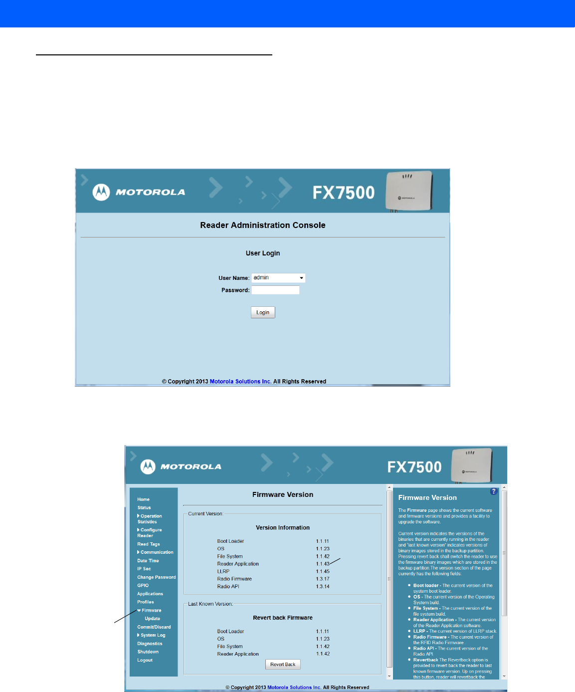
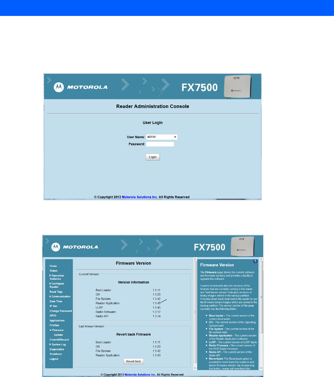
To verify that the FX7500 reader firmware is outdated:
1. Log into the reader. In the User Login window, enter admin in the User Name: field and enter change in the
Password: field.
Figure C-1
User Login Window
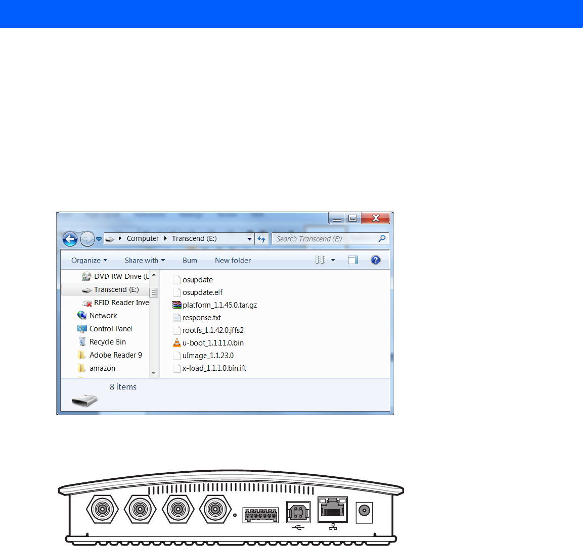
2. Select Firmware on the left side panel to verify that the current version of reader software is outdated,
e.g., 1.1.43.
Figure C-2
Firmware Version Window
Firmware
option
Version
number
C - 4 FX7500 RFID Reader Integrator Guide
Updating Methods
Download the reader update files from http://www.motorolasolutions.com/support, then use one of three
methods to update the reader software to a later version, e.g., 1.1.45.0 or higher:
•
Update Using a USB Drive (Recommended)
•
File-Based Update on page C-6
•
FTP-Based Update on page C-8
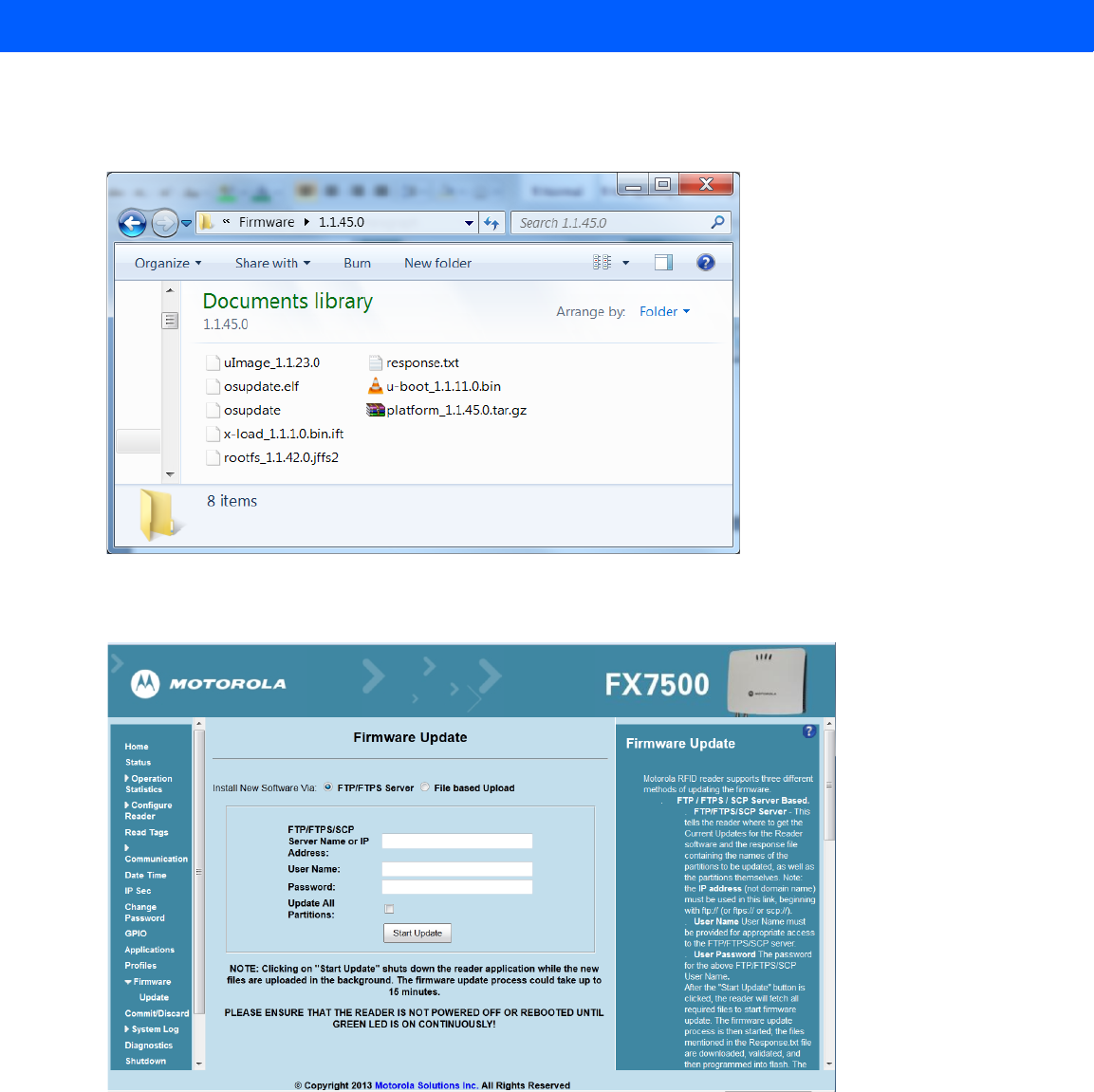
Update Using a USB Drive (Recommended)
1. Copy all reader update files into the root folder of the USB drive.
Figure C-3
USB Drive Root Folder
2. Insert the USB drive into the USB host port of the FX7500 RFID reader.
Figure C-4
USB Host Port Window
The reader starts the update process in 5-7 seconds, and indicates progress as follows:
•The reader continuously blinks the Power LED red.
•The reader blinks all 4 LEDs orange once.
•The reader Power LED remains steady orange.
•The reader Power LED settles to a steady green to indicate that the update is complete.
Port 1 Port 2 Port 3 Port 4 GPIO 24 VD
New Pic with USB Host Port to Come

FTP Firmware Upgrade C - 5
Figure C-5
Reader LEDs
New Pic with LED Labels to Come
Power LED
C - 6 FX7500 RFID Reader Integrator Guide
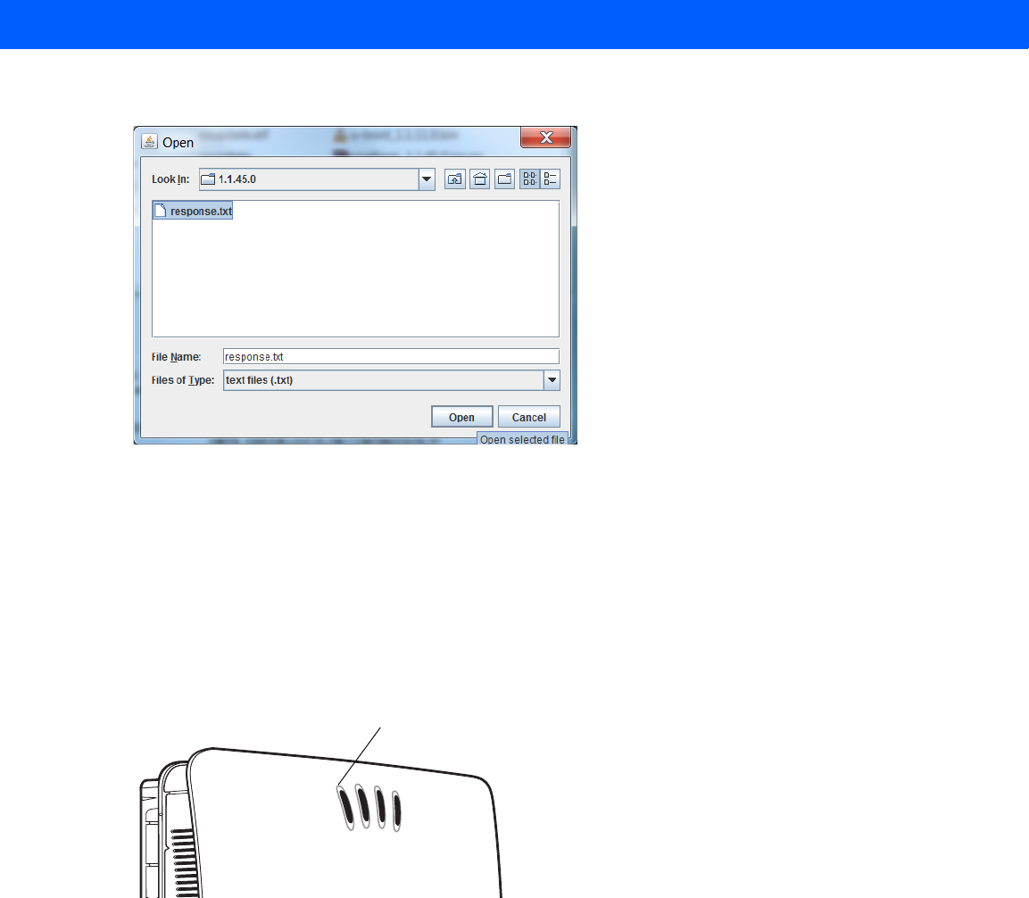
File-Based Update
1. Copy all reader update files into any folder on a host computer.
Figure C-6
Host Computer Folder
2. Log into the reader and navigate to the Firmware Update page.
Figure C-7
Firmware Update Window
3. Select File based Upload.
FTP Firmware Upgrade C - 7
4. Click on Browse and navigate to the folder that contains the firmware update files.
Figure C-8
Browsing Update Files
5. Select response.txt and click Open.
6. Click Start Update. The reader starts the update process and displays the update status as follows:
•The reader continuously blinks the Power LED red.
•The reader blinks all 4 LEDs orange once.
•The reader Power LED remains steady orange.
•The reader Power LED settles to a steady green to indicate that the update is complete.
Figure C-9
Reader LEDs
When the update completes, the reader reboots and returns to the FX7500 login screen.
New Pic with LED Labels to Come
Power LED
C - 8 FX7500 RFID Reader Integrator Guide
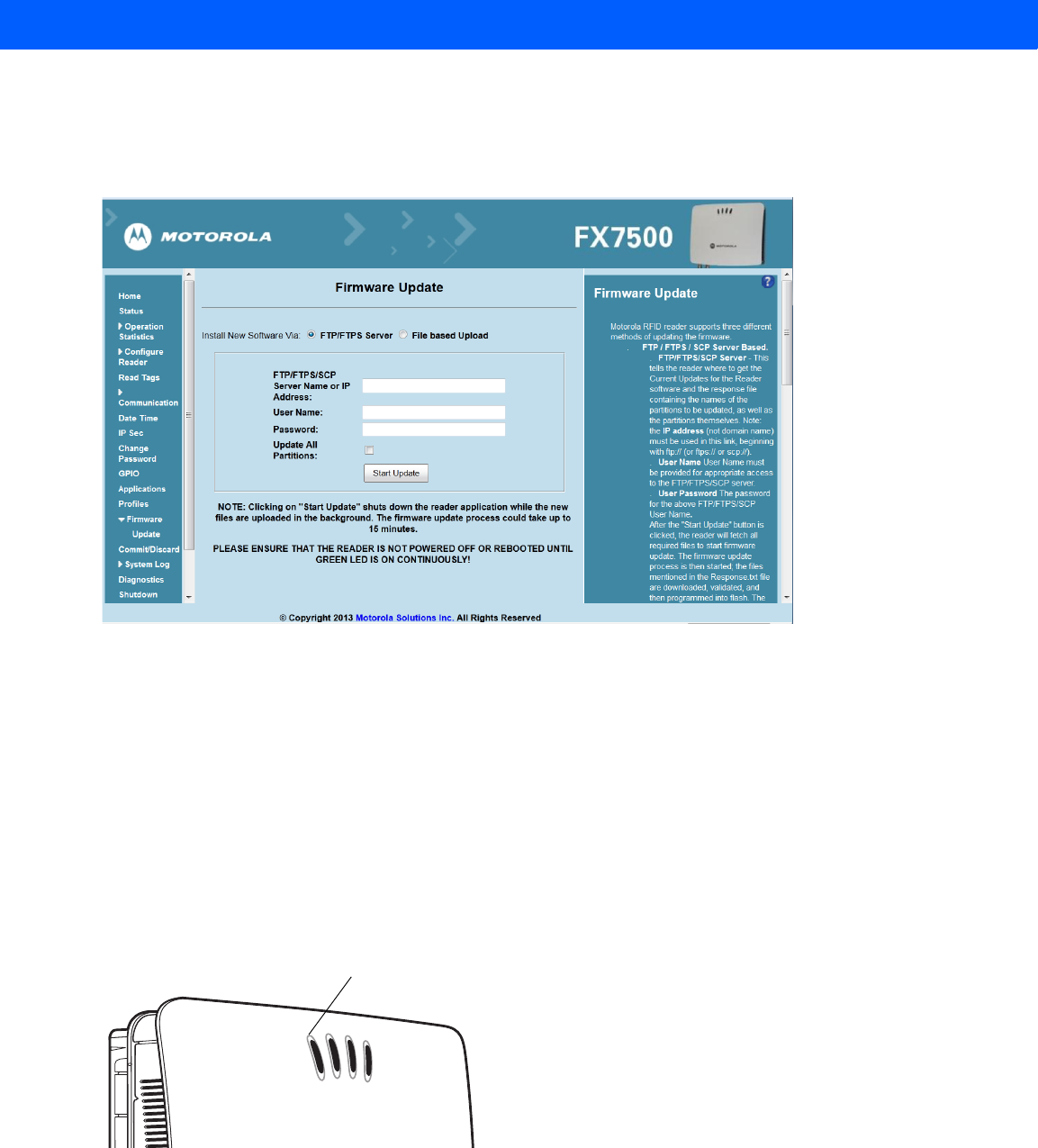
FTP-Based Update
Copy all the update files into an appropriate FTP location.
1. Log into the reader and navigate to the Firmware Update page.
Figure C-10
Firmware Update Window
2. Select FTP/FTPS Server.
3. Enter the FTP location where the files are located.
4. Enter the User Name and Password for the FTP server login.
5. Click Start Update. The reader starts the update process and displays the update status as follows:
•The reader continuously blinks the Power LED red.
•The reader blinks all 4 LEDs orange once.
•The reader Power LED remains steady orange.
•The reader Power LED settles to a steady green to indicate that the update is complete.
Figure C-11
Reader LEDs
When the update completes, the reader reboots and returns to the FX7500 login screen.
New Pic with LED Labels to Come
Power LED
FTP Firmware Upgrade C - 9
Verifying Firmware Version
To verify reader update success:
1. Log into the reader. In the User Login window, enter admin in the User Name: field and enter change in the
Password: field.
Figure C-12
User Login Window
2. Select Firmware on the left side panel to verify that the current version of reader software is the new
version number, e.g., 1.1.45, which indicates that the update was successful.
Figure C-13
Firmware Version Window
New
version
number

C - 10 FX7500 RFID Reader Integrator Guide
APPENDIX D STATIC IP CONFIGURATION
Introduction
This appendix describes three methods of setting the static IP address on an FX7500 RFID Reader.
Reader IP Address or Host Name is Known - Set the Static IP Using the Web
Console
1. Browse the device using the host name, e.g., FX7500CD3B1E.
2. Log onto the device.
Figure D-1
Reader Administration Console Login Window
3. Click Communication.
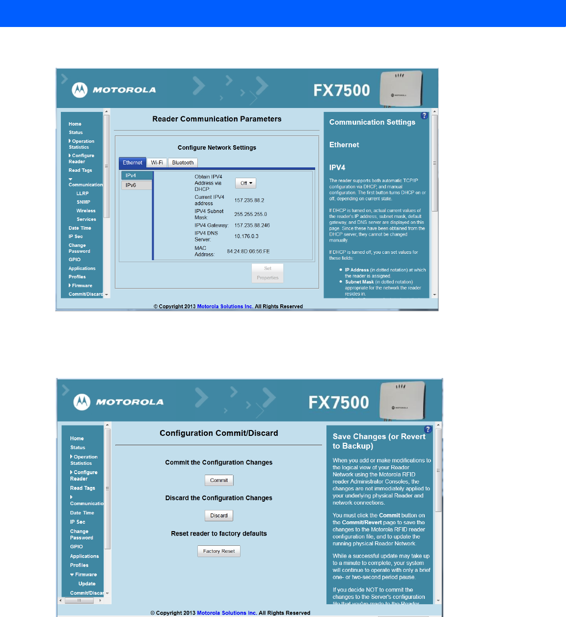
D - 2 FX7500 RFID Reader Integrator Guide
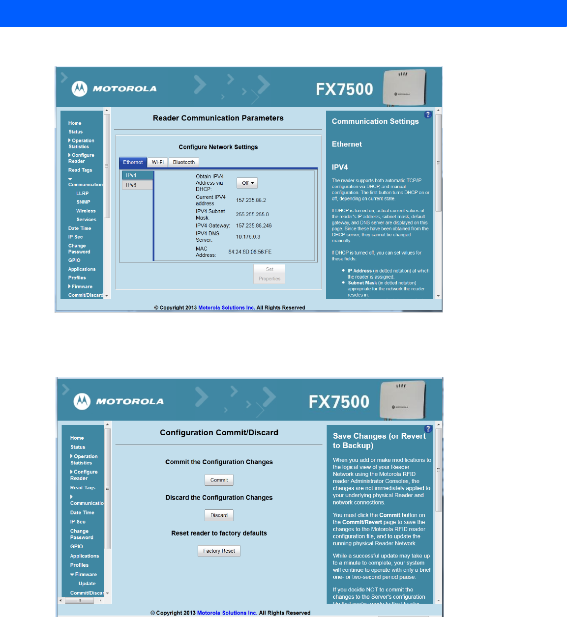
4. Set Obtain IP Address via DHCP to Off and enter all required information.
Figure D-2
Reader Communication Parameters Window
5. Click Set Properties. You can set a static IP that doesn't belong to this DHCP network.
6. Click Commit/Discard, then click the Commit button.
Figure D-3
Commit/Discard Window
7. The message Reader IP Address config has changed. Needs reader reboot to take effect appears. Reset the
device and use the reader with the static IP network.
Static IP Configuration D - 3
Reader IP is Not Known (DHCP Network Not Available) - Set the Static IP Using
the Web Console
1. Connect the device and a PC running Windows XP to the same network that doesn't have a DHCP server,
or connect the device directly to the PC.
2. Ensure both the device and PC Ethernet jack use at least one LED to indicate network connection detect.
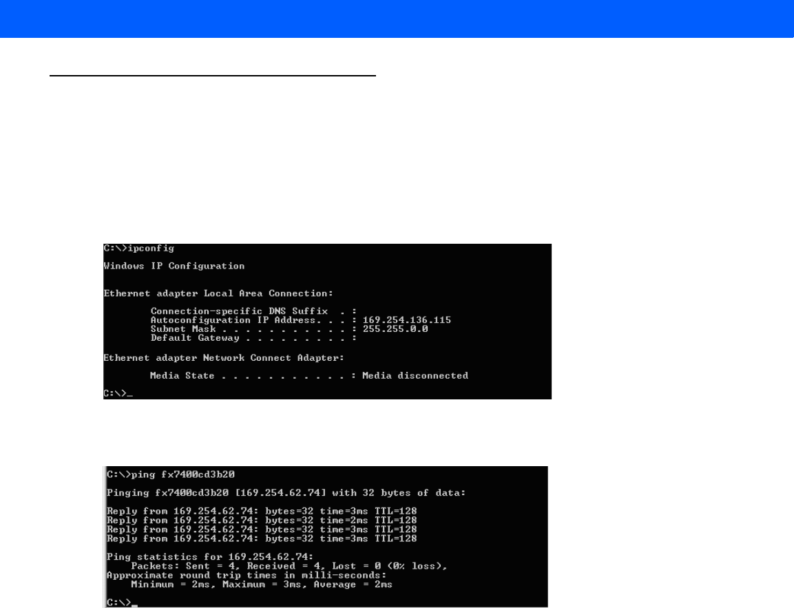
3. If the PC uses an assigned static IP, update it to use DHCP. The PC obtains an IP that starts with 169.
Figure D-4
Obtain IP Address
4. When possible, ping the host name of the device.
Figure D-5
Ping the Host Name
5. Use a browser to connect to the device with the host name, e.g., FX7500CD3B1E, or use the IP address
obtained from ping replies (e.g. 169.254.62.74).
6. Log onto the device.
7. Click Communication.
D - 4 FX7500 RFID Reader Integrator Guide
8. Set Obtain IP Address via DHCP to Off and enter all required information.
Figure D-6
Reader Communication Parameters Window
9. Click Set Properties.
10. Click Commit/Discard, then click the Commit button.
Figure D-7
Commit/Discard Window
11. The message Reader IP Address config has changed. Needs reader reboot to take effect appears. Reset the
device and use the reader with the static IP network.

APPENDIX E RF AIR LINK CONFIGURATION
Introduction
This appendix lists the different air link configurations supported. The air link configuration is available through
LLRP and RFID3 API interfaces.
Radio Modes
The supported modes are exposed as a list of individual UHFC1G2RfModeTableEntry parameters in regulatory
capabilities as shown in Table E-1 and Table E-2. The Mode Index column refers to the index used to walk the
C1G2UHFRFModeTable. Refer to the EPCglobal Low Level Reader Protocol (LLRP) Standard.
Table E-1
Radio Modes for FCC Readers
RF Mode
Index
Divide
Ratio
BDR
Value
M Value
M2=2,
FM0=1,
M4=4,
M8=8
FLM
Value
PIE
Value
Min
Tari
Max
Tari
Step
Tari
Spectral
Mask
Indicator
EPC HAG
T&C
Conform-
ance
1 64/3 640000 1 PR_ASK 1500 6250 6250 0 Single false
2 64/3 640000 1 PR_ASK 2000 6250 6250 0 Single false
3 64/3 120000 2 PR_ASK 1500 25000 25000 0 Single false
4 64/3 120000 2 PR_ASK 1500 12500 23000 2100 Single false
5 64/3 120000 2 PR_ASK 2000 25000 25000 0 Single false
6 64/3 120000 2 PR_ASK 2000 12500 23000 2100 Single false
7 64/3 128000 2 PR_ASK 1500 25000 25000 0 Single false
8 64/3 128000 2 PR_ASK 1500 12500 23000 2100 Single false
9 64/3 128000 2 PR_ASK 2000 25000 25000 0 Single false
*RF Mode 13 is the default air link profile.
**RF Mode 23 is the automac air link profile.

E - 2 FX7500 RFID Reader Integrator Guide
10 64/3 128000 2 PR_ASK 2000 12500 23000 2100 Single false
11 64/3 160000 2 PR_ASK 1500 12500 18800 2100 Single false
12 64/3 160000 2 PR_ASK 2000 12500 18800 2100 Single false
*13 64/3 60000 4 PR_ASK 1500 25000 25000 0 Dense false
14 64/3 60000 4 PR_ASK 1500 12500 23000 2100 Dense false
15 64/3 60000 4 PR_ASK 2000 25000 25000 0 Dense false
16 64/3 60000 4 PR_ASK 2000 12500 23000 2100 Dense false
17 64/3 64000 4 PR_ASK 1500 25000 25000 0 Dense false
18 64/3 64000 4 PR_ASK 1500 12500 23000 2100 Dense false
19 64/3 64000 4 PR_ASK 2000 25000 25000 0 Dense false
20 64/3 64000 4 PR_ASK 2000 12500 23000 2100 Dense false
21 64/3 80000 4 PR_ASK 1500 12500 18800 2100 Dense false
22 64/3 80000 4 PR_ASK 2000 12500 18800 2100 Dense false
**23 64/3 variable variable PR_ASK variable 6250 25000 variable variable false
24 64/3 320000 1 PR_ASK 1500 12500 18800 2100 Single false
25 64/3 320000 1 PR_ASK 2000 12500 18800 2100 Single false
26 64/3 30000 8 PR_ASK 1500 25000 25000 0 Dense false
27 64/3 30000 8 PR_ASK 1500 12500 23000 2100 Dense false
28 64/3 30000 8 PR_ASK 2000 25000 25000 0 Dense false
29 64/3 30000 8 PR_ASK 2000 12500 23000 2100 Dense false
30 64/3 32000 8 PR_ASK 1500 25000 25000 0 Dense false
31 64/3 32000 8 PR_ASK 1500 12500 23000 2100 Dense false
32 64/3 32000 8 PR_ASK 2000 25000 25000 0 Dense false
33 64/3 32000 8 PR_ASK 2000 12500 23000 2100 Dense false
34 64/3 40000 8 PR_ASK 1500 12500 18800 2100 Dense false
35 64/3 40000 8 PR_ASK 2000 12500 18800 2100 Dense false
Table E-1
Radio Modes for FCC Readers (Continued)
RF Mode
Index
Divide
Ratio
BDR
Value
M Value
M2=2,
FM0=1,
M4=4,
M8=8
FLM
Value
PIE
Value
Min
Tari
Max
Tari
Step
Tari
Spectral
Mask
Indicator
EPC HAG
T&C
Conform-
ance
*RF Mode 13 is the default air link profile.
**RF Mode 23 is the automac air link profile.

RF Air Link Configuration E - 3
Table E-2
Radio Modes for ETSI Readers
RF Mode
Index
Divide
Ratio
BDR
Value
M Value
M2=2,
FM0=1,
M4=4,
M8=8
FLM
Value
PIE
Value
Min
Tari
Max
Tari
Step
Tari
Spectral
Mask
Indicator
EPC HAG
T&C
Conform-
ance
1 64/3 120000 2 PR_ASK 1500 25000 25000 0 Single false
2 64/3 120000 2 PR_ASK 1500 12500 23000 2100 Single false
3 64/3 120000 2 PR_ASK 2000 25000 25000 0 Single false
4 64/3 120000 2 PR_ASK 2000 12500 23000 2100 Single false
5 64/3 128000 2 PR_ASK 1500 25000 25000 0 Single false
6 64/3 128000 2 PR_ASK 1500 12500 23000 2100 Single false
7 64/3 128000 2 PR_ASK 2000 25000 25000 0 Single false
8 64/3 128000 2 PR_ASK 2000 12500 23000 2100 Single false
9 64/3 160000 2 PR_ASK 1500 12500 18800 2100 Single false
10 64/3 160000 2 PR_ASK 2000 12500 18800 2100 Single false
*11 64/3 60000 4 PR_ASK 1500 25000 25000 0 Dense false
12 64/3 60000 4 PR_ASK 1500 12500 23000 2100 Dense false
13 64/3 60000 4 PR_ASK 2000 25000 25000 0 Dense false
14 64/3 60000 4 PR_ASK 2000 12500 23000 2100 Dense false
15 64/3 64000 4 PR_ASK 1500 25000 25000 0 Dense false
16 64/3 64000 4 PR_ASK 1500 12500 23000 2100 Dense false
17 64/3 64000 4 PR_ASK 2000 25000 25000 0 Dense false
18 64/3 64000 4 PR_ASK 2000 12500 23000 2100 Dense false
19 64/3 80000 4 PR_ASK 1500 12500 18800 2100 Dense false
20 64/3 80000 4 PR_ASK 2000 12500 18800 2100 Dense false
**21 64/3 variable variable PR_ASK variable 12500 25000 variable variable false
22 64/3 320000 1 PR_ASK 1500 12500 18800 2100 Single false
23 64/3 320000 1 PR_ASK 2000 12500 18800 2100 Single false
24 64/3 30000 8 PR_ASK 1500 25000 25000 0 Dense false
25 64/3 30000 8 PR_ASK 1500 12500 23000 2100 Dense false
26 64/3 30000 8 PR_ASK 2000 25000 25000 0 Dense false
27 64/3 30000 8 PR_ASK 2000 12500 23000 2100 Dense false
*RF Mode 11 is the default air link profile.
**RF Mode 21 is the automac air link profile.

E - 4 FX7500 RFID Reader Integrator Guide
28 64/3 32000 8 PR_ASK 1500 25000 25000 0 Dense false
29 64/3 32000 8 PR_ASK 1500 12500 23000 2100 Dense false
30 64/3 32000 8 PR_ASK 2000 25000 25000 0 Dense false
31 64/3 32000 8 PR_ASK 2000 12500 23000 2100 Dense false
32 64/3 40000 8 PR_ASK 1500 12500 18800 2100 Dense false
33 64/3 40000 8 PR_ASK 2000 12500 18800 2100 Dense false
Table E-2
Radio Modes for ETSI Readers (Continued)
RF Mode
Index
Divide
Ratio
BDR
Value
M Value
M2=2,
FM0=1,
M4=4,
M8=8
FLM
Value
PIE
Value
Min
Tari
Max
Tari
Step
Tari
Spectral
Mask
Indicator
EPC HAG
T&C
Conform-
ance
*RF Mode 11 is the default air link profile.
**RF Mode 21 is the automac air link profile.

APPENDIX F CONNECTING WI-FI AND
BLUETOOTH DONGLES
Introduction
This appendix describes how to connect to a wireless network using a USB Wi-Fi dongle on the FX7500, and
how to connect to a peer device over Bluetooth using a USB Bluetooth dongle.
Connecting to a Wireless Network Using a Wi-Fi Dongle
To connect to a wireless network using a USB Wi-Fi dongle on the FX7500:
1. Plug the supported wireless dongle into the USB host port on the FX7500. Supported dongles are:
•
Wi-Fi over USB adapters with Realtek chipset RTL 8187
•
The following devices were tested:
•Alfa AWUS036H, visit http://www.alfa.com.tw/in/front/bin/ptlist.phtml?Category=10541
•CCrane Versa Wifi USB Adapter II, visit
http://www.ccrane.com/antennas/wifi-antennas/versa-wifi-usb-adapter-II.aspx
Figure F-1
USB Host Port Location for Dongle
Port 1 Port 2 Port 3 Port 4 GPIO 24 VDC
USB Host Port
F - 2 FX7500 RFID Reader Integrator Guide
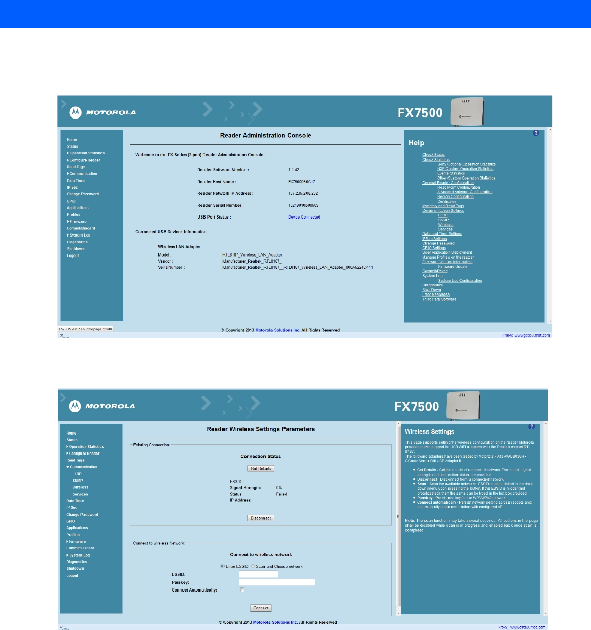
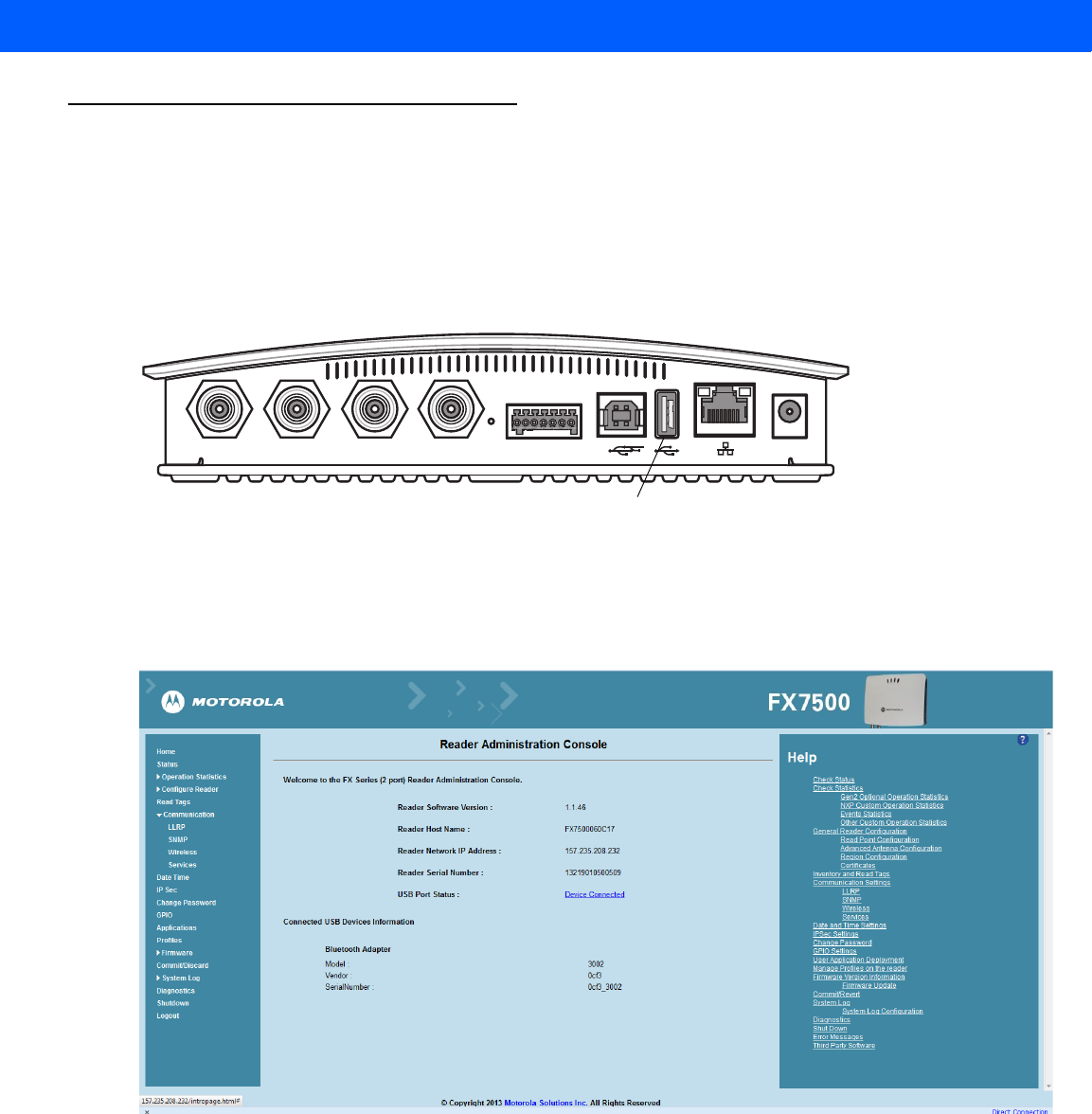
2. To confirm that the Wi-Fi dongle is detected properly, log in to the reader Administrator Console. On the
Home page ensure the USB Port Status displays Device Connected. Hover the mouse pointer over this link
to display the WiFi dongle information shown in Figure F-2.
Figure F-2
Wi-Fi Dongle Connected
3. Select Communication > Wireless.
Figure F-3
Wireless Settings
The WiFi dongle can connect to the wireless network in one of two ways:
•Manually entering the ESSID (if known).
•Scanning the current list of APs and choosing the correct one to connect to.
Connecting Wi-Fi and Bluetooth Dongles F - 3
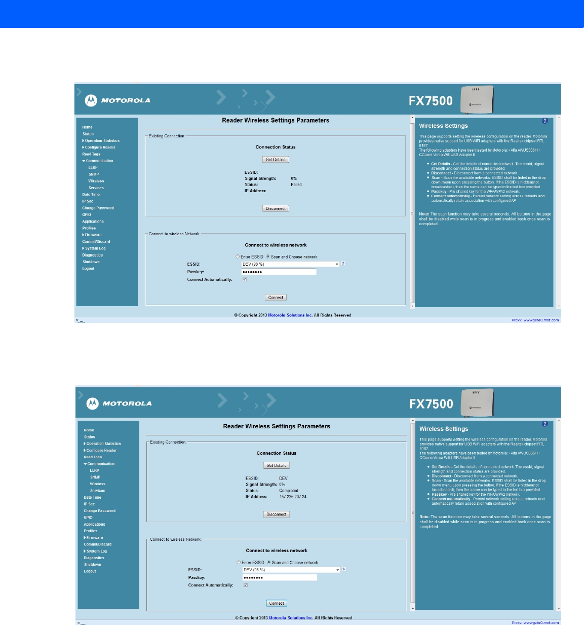
4. Once the APs are scanned, enter the appropriate passkey and enable Connect Automatically (if required to
connect to the AP automatically if the connection is lost).
Figure F-4
Entering Connect Information
5. Select Connect. When the connection to the AP succeeds, an IP is assigned and appears in the
IP Address field.
Figure F-5
Assigned IP Address
The reader is now accessible using the wireless IP shown in the IP Address field (157.235.207.24 in this case).
The WiFi interface supports dynamic addressing mechanisms for both IPV4 and IPv6. There is no provision to
set a static IP address.
For wireless IP address details, select Communication > Wi-Fi tab.
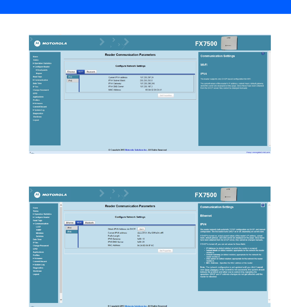
F - 4 FX7500 RFID Reader Integrator Guide
Figure F-6
Wi-Fi Tab - IPV4
The reader can also be accessed via Wi-Fi using an IPV6 address if supported by the network to which the API
is connected.
Figure F-7
Wi-Fi Tab - IPV6
Connecting Wi-Fi and Bluetooth Dongles F - 5
Connecting to a Peer Device over Bluetooth Using a Bluetooth Dongle
To connect to a peer device over Bluetooth using a USB Bluetooth dongle on the FX7500:
1. Plug the supported Bluetooth dongle into the USB host port on the FX7500. The following Bluetooth
dongles are supported on the FX7500:
•Asus Mini Bluetooth Dongle USB-BT211.
•MediaLink Bluetooth Dongle MUA-BA3.
Figure F-8
USB Host Port Location for Dongle
2. To confirm that the Bluetooth dongle is detected properly, log in to the reader Administrator Console. On
the Home page ensure the USB Port Status displays Device Connected. Hover the mouse pointer over this
link to display the Bluetooth dongle information.
Figure F-9
Bluetooth Dongle Connected
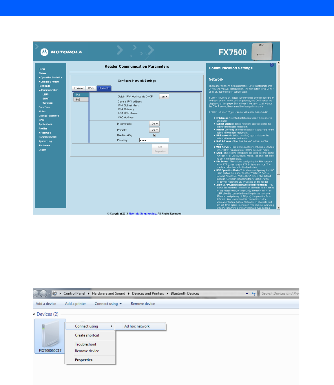
3. Select Communication > Bluetooth.
Port 1 Port 2 Port 3 Port 4 GPIO 24 VDC
USB Host Port
F - 6 FX7500 RFID Reader Integrator Guide
4. Change the Discoverable and Pairable properties to On.
Figure F-10
Changing Discoverable and Pairable Properties
5. Optionally select Use Passkey and enter a passkey to validate the Bluetooth connection. The default
passkey for the FX7500 is 0000.
6. Discover the reader from a Bluetooth-enabled device (such as a laptop). Use the host name to identify the
reader among the discovered devices (e.g., FX7500060C17).
7. After a successful connection, right-click the reader icon (e.g., FX7500060C17) in the list of Bluetooth
devices and select Connect using > Ad hoc network. This establishes the network connection for later.
Figure F-11
Connecting to the Reader
Connecting Wi-Fi and Bluetooth Dongles F - 7
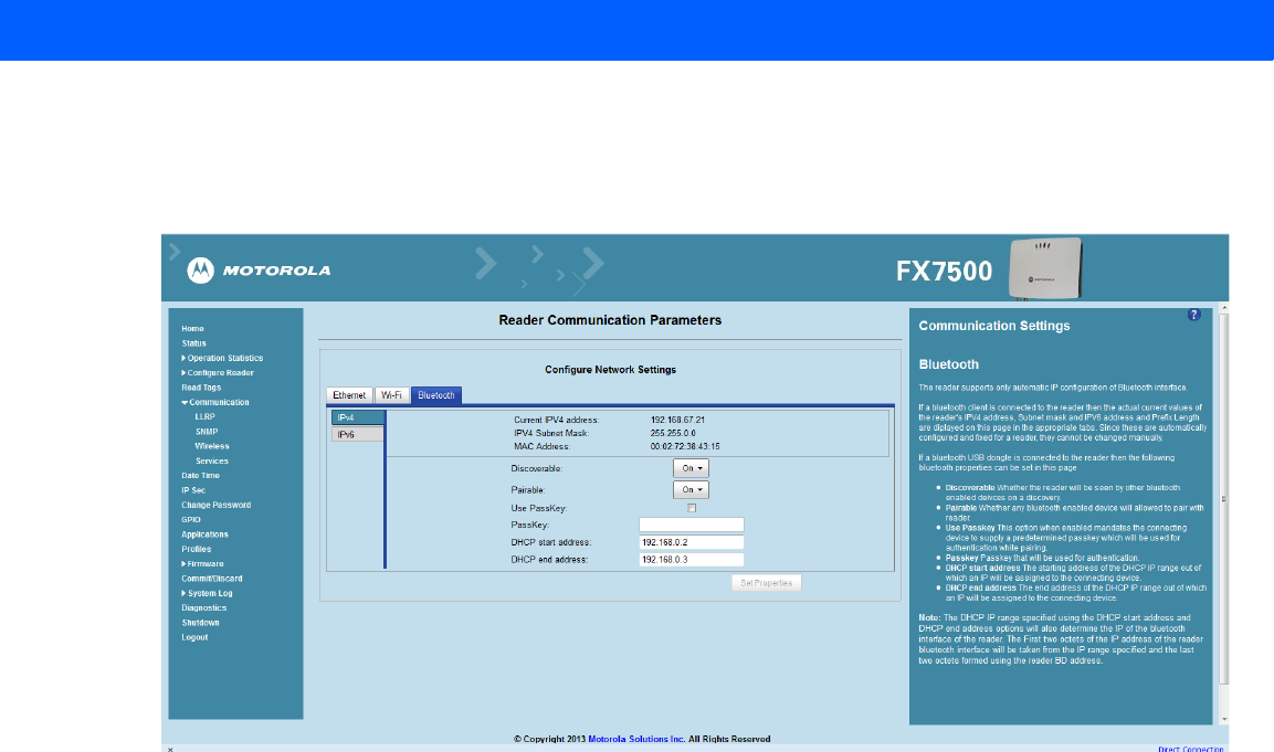
8. The IP address assigned to the Bluetooth interface is 192.168.XX.XX. The last 2 octets are the last 2
octets of the Bluetooth MAC address (found in the Properties window on the PC once the Bluetooth
connection is established). Also find this in the Communication > Bluetooth page. Both IPV4 and IPV6
based IP address are supported for adhoc Bluetooth connection between the reader and the client.
Figure F-12
Communication Bluetooth Tab
9. Open the web page or sample application to connect to the Bluetooth IP (192.168.67.21 in Figure F-12)
and read tags.

F - 8 FX7500 RFID Reader Integrator Guide

INDEX
Numerics
10/100BaseT Ethernet . . . . . . . . . . . . . . . . . . . . 1-2, 2-5
2-port reader . . . . . . . . . . . . . . . . . . . . . . . . . . . . . . . 2-4
4-port reader . . . . . . . . . . . . . . . . . . . . . . . . . . . . . . . 2-4
A
administrator console . . . . . . . . . . . . . . . . . . . . . . . . 4-1
applications . . . . . . . . . . . . . . . . . . . . . . . . . . . . 4-36
committing changes . . . . . . . . . . . . . . . . . . . . . 4-41
communication settings . . . . . . . . . . . . . . . . . . 4-23
configure network services . . . . . . . . . . . . . . . . 4-30
configure network settings . . . . . . . 4-23, 4-25, 4-26
configuring system log . . . . . . . . . . . . . . . . . . . 4-43
discarding changes . . . . . . . . . . . . . . . . . . . . . . 4-41
firmware version . . . . . . . . . . . . . . . . . . . . 4-39, 4-40
GPIO . . . . . . . . . . . . . . . . . . . . . . . . . . . . . . . . . 4-35
IPV6 sec . . . . . . . . . . . . . . . . . . . . . . . . . . . . . . 4-32
login . . . . . . . . . . . . . . . . . . . . . . . . . . . . . . . . . . 4-6
main screen . . . . . . . . . . . . . . . . . . . . . . . . . . . . 4-9
managing login . . . . . . . . . . . . . . . . . . . . . . . . . 4-34
reader diagnostics . . . . . . . . . . . . . . . . . . . . . . 4-44
reader profiles . . . . . . . . . . . . . . . . . . . . . . . . . . 4-37
scan control . . . . . . . . . . . . . . . . . . . . . . . . 1-6, 4-21
set password . . . . . . . . . . . . . . . . . . . . . . . . . . 4-33
setting date and time . . . . . . . . . . . . . . . . . . . . 4-31
shutting down . . . . . . . . . . . . . . . . . . . . . . . . . . 4-45
status . . . . . . . . . . . . . . . . . . . . . . . . . . . . . . . . 4-10
system log . . . . . . . . . . . . . . . . . . . . . . . . . . . . 4-42
air link . . . . . . . . . . . . . . . . . . . . . . . . . . . . . . . . . . . . E-1
antennas . . . . . . . . . . . . . . . . . . . . . . . . . . . . . . . . . . 2-2
configuring . . . . . . . . . . . . . . . . . . . . . . . . . . . . 4-18
installing . . . . . . . . . . . . . . . . . . . . . . . . . . . . . . . 3-4
ports . . . . . . . . . . . . . . . . . . . . . . . . . . . . . . . 1-2, 2-5
applications . . . . . . . . . . . . . . . . . . . . . . . . . . . . . . . 4-36
B
backup . . . . . . . . . . . . . . . . . . . . . . . . . . . . . . . . . . . . 2-7
bluetooth . . . . . . . . . . . . . . . . . . . . . . . . . . . . . . . . . . F-5
connecting . . . . . . . . . . . . . . . . . . . . . . . . . . . . . . F-5
C
cable pinouts . . . . . . . . . . . . . . . . . . . . . . . . . . . . . . . A-4
ethernet . . . . . . . . . . . . . . . . . . . . . . . . . . . . . . . . A-4
GPIO . . . . . . . . . . . . . . . . . . . . . . . . . . . . . . . . . . A-6
USB . . . . . . . . . . . . . . . . . . . . . . . . . . . . . . . . . . . A-5
USB client . . . . . . . . . . . . . . . . . . . . . . . . . . . . . . A-5
USB host . . . . . . . . . . . . . . . . . . . . . . . . . . . . . . . A-5
chapter descriptions . . . . . . . . . . . . . . . . . . . . . . . . . . . . x
client applications . . . . . . . . . . . . . . . . . . . . . . . . . . . . 2-7
commit region change . . . . . . . . . . . . . . . . . . . . . . . . 1-5
committing changes . . . . . . . . . . . . . . . . . . . . . . . . . 4-41
communication . . . . . . . . . . . . . . . . . . . . . . . . . . . . . . 2-5
ethernet, wired . . . . . . . . . . . . . . . . . . . . . . . . . . . 3-5
communication settings . . . . . . . . . . . . . . . . . . . . . . 4-23
configurations . . . . . . . . . . . . . . . . . . . . . . . . . . . . . . . ix
configure
administrator console . . . . . . . . . . . . . . . . . . . . . 2-7
antenna . . . . . . . . . . . . . . . . . . . . . . . . . . . . . . . 4-18
LLRP . . . . . . . . . . . . . . . . . . . . . . . . . . . . . . . . . 4-27
read points . . . . . . . . . . . . . . . . . . . . . . . . 4-17, 4-19
reader . . . . . . . . . . . . . . . . . . . . . . . . . . . . . . . . 4-16
region . . . . . . . . . . . . . . . . . . . . . . . . . . . . . . . . 4-20
SNMP . . . . . . . . . . . . . . . . . . . . . . . . . . . . . . . . 4-28
static IP . . . . . . . . . . . . . . . . . . . . . . . . . . . . . . . .D-1
static IP via web console . . . . . . . . . . . . . . . D-1, D-3
wireless . . . . . . . . . . . . . . . . . . . . . . . . . . . . . . . 4-29
configuring network
bluetooth . . . . . . . . . . . . . . . . . . . . . . . . . . . . . . 4-26
ethernet . . . . . . . . . . . . . . . . . . . . . . . . . . . . . . . 4-23
services . . . . . . . . . . . . . . . . . . . . . . . . . . . . . . . 4-30

Index - 2 FX7500 RFID Reader Integrator Guide
wi-fi . . . . . . . . . . . . . . . . . . . . . . . . . . . . . . . . . . 4-25
connecting
to reader . . . . . . . . . . . . . . . . . . . . . . . . . . . . . . . 4-3
via bluetooth . . . . . . . . . . . . . . . . . . . . . . . . . . . . F-5
via host name . . . . . . . . . . . . . . . . . . . . . . . . . . . 4-3
via IP address . . . . . . . . . . . . . . . . . . . . . . . . . . . 4-4
via wi-fi . . . . . . . . . . . . . . . . . . . . . . . . . . . . . . . . F-1
connection . . . . . . . . . . . . . . . . . . . . . . . . . . . . . . . . . 2-7
antennas . . . . . . . . . . . . . . . . . . . . . . . . . . . . . . . 3-4
communication . . . . . . . . . . . . . . . . . . . . . . . . . . 3-5
port diagram . . . . . . . . . . . . . . . . . . . . . . . . . . . . 2-5
ports . . . . . . . . . . . . . . . . . . . . . . . . . . . . . . . . . . 2-4
powering . . . . . . . . . . . . . . . . . . . . . . . . . . . . . . 3-10
wired ethernet . . . . . . . . . . . . . . . . . . . . . . . . . . . 3-5
conventions
notational . . . . . . . . . . . . . . . . . . . . . . . . . . . . . . . . x
country list . . . . . . . . . . . . . . . . . . . . . . . . . . . . . .1-5, 4-7
D
date . . . . . . . . . . . . . . . . . . . . . . . . . . . . . . . . . . . . . 4-31
deployments . . . . . . . . . . . . . . . . . . . . . . . . . . . . . . . 4-2
discarding changes . . . . . . . . . . . . . . . . . . . . . . . . . 4-41
E
ethernet
Bias-T port connection . . . . . . . . . . . . . . . . . . . . 3-6
pinouts . . . . . . . . . . . . . . . . . . . . . . . . . . . . . . . . A-4
POE . . . . . . . . . . . . . . . . . . . . . . . . . . . . . . . . . . 3-5
port . . . . . . . . . . . . . . . . . . . . . . . . . . . . . . . . . . . 2-5
setup . . . . . . . . . . . . . . . . . . . . . . . . . . . . . . . . . . 3-5
wired . . . . . . . . . . . . . . . . . . . . . . . . . . . . . . . . . . 3-5
event management, tags . . . . . . . . . . . . . . . . . . . . . . 2-7
event statistics . . . . . . . . . . . . . . . . . . . . . . . . . . . . . 4-14
F
filtering, tags . . . . . . . . . . . . . . . . . . . . . . . . . . . . . . . 2-7
firmware
updating . . . . . . . . . . . . . . . . . . . . . . . . . . . . . . . 2-7
version . . . . . . . . . . . . . . . . . . . . . . . . . . .4-39, 4-40
firmware update . . . . . . . . . . . . . . . . 4-39, 4-40, C-1, C-3
prerequisites . . . . . . . . . . . . . . . . . . . . . . . . . . . . C-1
first time login . . . . . . . . . . . . . . . . . . . . . . . . . . .1-3, 4-6
G
GPIO . . . . . . . . . . . . . . . . . . . . . . . . . . . . . . . . . .1-2, 2-5
pinouts . . . . . . . . . . . . . . . . . . . . . . . . . . . . . . . . A-6
port . . . . . . . . . . . . . . . . . . . . . . . . . . . . . . . . . . . 2-5
GPIO control . . . . . . . . . . . . . . . . . . . . . . . . . . . . . . 4-35
H
host communication
ethernet, wired . . . . . . . . . . . . . . . . . . . . . . . . . . . 3-5
host name connect . . . . . . . . . . . . . . . . . . . . . . . . . . . 1-2
I
information, service . . . . . . . . . . . . . . . . . . . . . . . . . . . xi
initiating reads . . . . . . . . . . . . . . . . . . . . . . . . . 1-6, 4-21
installation
antennas . . . . . . . . . . . . . . . . . . . . . . . . . . . . . . . 3-4
communication connection . . . . . . . . . . . . . . . . . 3-5
mounting . . . . . . . . . . . . . . . . . . . . . . . . . . . . . . . 3-2
powering . . . . . . . . . . . . . . . . . . . . . . . . . . . . . . 3-10
IP address . . . . . . . . . . . . . . . . . . . . . . . . . . . . . . . . . 4-5
IP ping . . . . . . . . . . . . . . . . . . . . . . . . . . . . . . . . . . . . 4-5
K
kill tag . . . . . . . . . . . . . . . . . . . . . . . . . . . . . . . . . . . . . 2-7
kits . . . . . . . . . . . . . . . . . . . . . . . . . . . . . . . . . . . 2-4, A-1
L
LEDs . . . . . . . . . . . . . . . . . . . . . . . . . . . . . . . . . . . . . . 2-6
LLRP . . . . . . . . . . . . . . . . . . . . . . . . . . . . . . . . . . . . . 2-7
configure . . . . . . . . . . . . . . . . . . . . . . . . . . . . . . 4-27
extensions . . . . . . . . . . . . . . . . . . . . . . . . . . . . . .B-1
radio modes . . . . . . . . . . . . . . . . . . . . . . . . . E-1, E-3
lock tag . . . . . . . . . . . . . . . . . . . . . . . . . . . . . . . . . . . . 2-7
log . . . . . . . . . . . . . . . . . . . . . . . . . . . . . . . . . . . . . . . 4-42
configuring . . . . . . . . . . . . . . . . . . . . . . . . . . . . . 4-43
logging . . . . . . . . . . . . . . . . . . . . . . . . . . . . . . . . . . . . 2-7
login . . . . . . . . . . . . . . . . . . . . . . . . . . . . . . . . . . . . . . 4-6
first time . . . . . . . . . . . . . . . . . . . . . . . . . . . . . . . . 4-6
managing . . . . . . . . . . . . . . . . . . . . . . . . . . . . . . 4-34
M
mono-static . . . . . . . . . . . . . . . . . . . . . . . . . . . . . . . . . 2-4
mounting . . . . . . . . . . . . . . . . . . . . . . . . . . . . . . . . . . . 3-2
mounting plate . . . . . . . . . . . . . . . . . . . . . . . . . . . . . . 3-2
multiple reader deployments . . . . . . . . . . . . . . . . . . . 4-2
N
NXP
statistics . . . . . . . . . . . . . . . . . . . . . . . . . . 4-13, 4-15
O
obtain reader IP address . . . . . . . . . . . . . . . . . . . . . . 4-5

Index - 3
P
Password . . . . . . . . . . . . . . . . . . . . . . . . . .1-3, C-3, C-9
password . . . . . . . . . . . . . . . . . . . . . . . 1-3, 4-6, C-3, C-9
changing . . . . . . . . . . . . . . . . . . . . . . . . . . . . . . 4-33
pinouts . . . . . . . . . . . . . . . . . . . . . . . . . . . . . . . . . . . A-4
ethernet . . . . . . . . . . . . . . . . . . . . . . . . . . . . . . . A-4
GPIO . . . . . . . . . . . . . . . . . . . . . . . . . . . . . . . . . . A-6
USB . . . . . . . . . . . . . . . . . . . . . . . . . . . . . . . . . . A-5
USB client . . . . . . . . . . . . . . . . . . . . . . . . . . . . . . A-5
USB host . . . . . . . . . . . . . . . . . . . . . . . . . . . . . . A-5
POE . . . . . . . . . . . . . . . . . . . . . . 1-2, 2-5, 3-5, 3-10, A-4
ports . . . . . . . . . . . . . . . . . . . . . . . . . . . . . . . . . . . . . 2-4
descriptions . . . . . . . . . . . . . . . . . . . . . . . . . . . . 2-5
ethernet . . . . . . . . . . . . . . . . . . . . . . . . . . . . . . . 3-5
power . . . . . . . . . . . . . . . . . . . . . . . . . . . . . . . . . 1-2, 2-5
AC power supply . . . . . . . . . . . . . . . . . . . . . . . 3-10
applying . . . . . . . . . . . . . . . . . . . . . . . . . . . . . . 3-10
options . . . . . . . . . . . . . . . . . . . . . . . . . . . . . . . 3-10
POE . . . . . . . . . . . . . . . . . . . . . . . . . . . . . . 3-5, 3-10
port . . . . . . . . . . . . . . . . . . . . . . . . . . . . . . . . . . . 2-5
profiles . . . . . . . . . . . . . . . . . . . . . . . . . . . . . . . . . . 4-37
R
read points . . . . . . . . . . . . . . . . . . . . . . . . . . . 4-17, 4-19
reader
configuration . . . . . . . . . . . . . . . . . . . . . . . . . . . 4-16
configurations . . . . . . . . . . . . . . . . . . . . . . . . . . . . . ix
connecting . . . . . . . . . . . . . . . . . . . . . . . . . . . . . 4-3
description . . . . . . . . . . . . . . . . . . . . . . . . . . . . . 2-2
GEN2 statistics . . . . . . . . . . . . . . . . . . . . . . . . . 4-12
kits . . . . . . . . . . . . . . . . . . . . . . . . . . . . . . . .2-4, A-1
profiles . . . . . . . . . . . . . . . . . . . . . . . . . . . . . . . 4-37
statistics . . . . . . . . . . . . . . . . . . . . . . . . . . . . . . 4-11
event . . . . . . . . . . . . . . . . . . . . . . . . . . . . . 4-14
NXP . . . . . . . . . . . . . . . . . . . . . . . . . . 4-13, 4-15
status . . . . . . . . . . . . . . . . . . . . . . . . . . . . . . . . 4-10
versions . . . . . . . . . . . . . . . . . . . . . . . . . . . . . . . 2-4
reading tags . . . . . . . . . . . . . . . . . . . . . . . . . . . 2-7, 3-12
initiating . . . . . . . . . . . . . . . . . . . . . . . . . . . 1-6, 4-21
rear panel . . . . . . . . . . . . . . . . . . . . . . . . . . . . . . 1-2, 2-5
reboot . . . . . . . . . . . . . . . . . . . . . . . . . . . . . . . . . . . . 4-2
recovery . . . . . . . . . . . . . . . . . . . . . . . . . . . . . . . . . . 2-7
region . . . . . . . . . . . . . . . . . . . . . . . . . . . . . . . . . . . . 4-7
region configuration . . . . . . . . . . . . . . . . . . . . . . . . 4-20
region control . . . . . . . . . . . . . . . . . . . . . . . . . . . . . . 4-7
region setting . . . . . . . . . . . . . . . . . . . . . . . . . . . . . . 1-4
region settings . . . . . . . . . . . . . . . . . . . . . . . . . . . . . . 1-4
reset . . . . . . . . . . . . . . . . . . . . . . . . . . . . . . . . . . 1-2, 2-5
RFID
FX reader . . . . . . . . . . . . . . . . . . . . . . . . . . . . . . 2-3
overview . . . . . . . . . . . . . . . . . . . . . . . . . . . . . . . 2-1
RFID components . . . . . . . . . . . . . . . . . . . . . . . . . . . 2-2
antennas . . . . . . . . . . . . . . . . . . . . . . . . . . . . . . . 2-2
readers . . . . . . . . . . . . . . . . . . . . . . . . . . . . . . . . 2-2
tags . . . . . . . . . . . . . . . . . . . . . . . . . . . . . . . . . . . 2-2
RJ45 . . . . . . . . . . . . . . . . . . . . . . . . . . . . . . . . . . . . . 2-5
RM extensions . . . . . . . . . . . . . . . . . . . . . . . . . . . . . . B-1
S
service information . . . . . . . . . . . . . . . . . . . . . . . . . . . . xi
set region . . . . . . . . . . . . . . . . . . . . . . . . . . . . . . 1-4, 4-7
setting date . . . . . . . . . . . . . . . . . . . . . . . . . . . . . . . 4-31
setting time . . . . . . . . . . . . . . . . . . . . . . . . . . . . . . . 4-31
setup
POE . . . . . . . . . . . . . . . . . . . . . . . . . . . . . . . . . . 3-10
power supply . . . . . . . . . . . . . . . . . . . . . . . . . . . 3-10
wired ethernet . . . . . . . . . . . . . . . . . . . . . . . . . . . 3-5
wired ethernet AC outlet . . . . . . . . . . . . . . . . . . . 3-5
wired ethernet, power-over . . . . . . . . . . . . . . . . . 3-5
shutdown . . . . . . . . . . . . . . . . . . . . . . . . . . . . . . . . . 4-45
SNMP . . . . . . . . . . . . . . . . . . . . . . . . . . . . . . . . . . . . 2-7
configure . . . . . . . . . . . . . . . . . . . . . . . . . . . . . . 4-28
software update . . . . . . . . . . . . . . . . . . . . . . . . . . . . . C-3
specifications . . . . . . . . . . . . . . . . . . . . . . . . . . . . . . . A-2
start-up . . . . . . . . . . . . . . . . . . . . . . . . . . . . . . . . . . . . 1-3
static IP configuration . . . . . . . . . . . . . . . . . . . . . . . . .D-1
via web console . . . . . . . . . . . . . . . . . . . . . . D-1, D-3
Statistics . . . . . . . . . . . . . . . . . . . . . . . . . . . . . . . . . 4-14
statistics . . . . . . . . . . . . . . . . . . . . . . . . . . . . . . . . . . 4-11
event . . . . . . . . . . . . . . . . . . . . . . . . . . . . . . . . . 4-14
GEN2 . . . . . . . . . . . . . . . . . . . . . . . . . . . . . . . . . 4-12
NXP . . . . . . . . . . . . . . . . . . . . . . . . . . . . . 4-13, 4-15
status . . . . . . . . . . . . . . . . . . . . . . . . . . . . . . . . . . . . 4-10
system log . . . . . . . . . . . . . . . . . . . . . . . . . . . . . . . . 4-42
configuring . . . . . . . . . . . . . . . . . . . . . . . . . . . . . 4-43
system time . . . . . . . . . . . . . . . . . . . . . . . . . . . . . . . 4-31
T
tags . . . . . . . . . . . . . . . . . . . . . . . . . . . . . . . . . . . . . . 2-2
management . . . . . . . . . . . . . . . . . . . . . . . . . . . . 2-7
reading . . . . . . . . . . . . . . . . . . . . . . . . . . 3-12, 4-21
technical specifications . . . . . . . . . . . . . . . . . . . . . . . A-2
time . . . . . . . . . . . . . . . . . . . . . . . . . . . . . . . . . . . . . 4-31
troubleshooting . . . . . . . . . . . . . . . . . . . . . . . . . . . . . 5-1
U
unpacking . . . . . . . . . . . . . . . . . . . . . . . . . . . . . . . . . 3-1
updating firmware . . . . . . . . . . 2-7, 4-39, 4-40, C-1, C-3
prerequisites . . . . . . . . . . . . . . . . . . . . . . . . . . . .C-1
updating software . . . . . . . . . . . . . . . . . . . . . . . . . . . C-3
USB . . . . . . . . . . . . . . . . . . . . . . . . . . . . . . . . . . 1-2, 2-5
client pinouts . . . . . . . . . . . . . . . . . . . . . . . . . . . . A-5

Index - 4 FX7500 RFID Reader Integrator Guide
host pinouts . . . . . . . . . . . . . . . . . . . . . . . . . . . . . A-5
pinouts . . . . . . . . . . . . . . . . . . . . . . . . . . . . . . . . A-5
user ID . . . . . . . . . . . . . . . . . . . . . . . . . . . . . . . . . . . . 4-6
user name . . . . . . . . . . . . . . . . . . . . . . . . . 1-3, C-3, C-9
user password . . . . . . . . . . . . . . . . . . . . . . . . . . . . . . 4-6
V
version control . . . . . . . . . . . . . . . . . . . . . . . . .4-39, 4-40
W
wi-fi . . . . . . . . . . . . . . . . . . . . . . . . . . . . . . . . . . . . . . F-1
connecting . . . . . . . . . . . . . . . . . . . . . . . . . . . . . . F-1
wired ethernet . . . . . . . . . . . . . . . . . . . . . . . . . . . . . . 3-5
wireless
configure . . . . . . . . . . . . . . . . . . . . . . . . . . . . . . 4-29
write tag . . . . . . . . . . . . . . . . . . . . . . . . . . . . . . . . . . . 2-7
Z
zero-configuration networking . . . . . . . . . . . . . . . . . . 4-5

MN000026A01 Revision .5 - November 2013
Motorola Solutions, Inc.
One Motorola Plaza
Holtsville, New York 11742, USA
1-800-927-9626
http://www.motorolasolutions.com
MOTOROLA, MOTO, MOTOROLA SOLUTIONS and the Stylized M Logo are trademarks or registered
trademarks of Motorola Trademark Holdings, LLC and are used under license. All other trademarks are
the property of their respective owners.
© 2013 Motorola Solutions, Inc. All Rights Reserved.