Zebra Technologies MC55N0 ENTERPRISE DIGITAL ASSISTANT (EDA) User Manual REVISED 6
Zebra Technologies Corporation ENTERPRISE DIGITAL ASSISTANT (EDA) REVISED 6
UserManual.wiki
>
Zebra Technologies
>
MC55N0 User Manual
>
REVISED USER MANUAL 6
Contents
1.
Users Manual
2.
USERS MANUAL
3.
REVISED USER MANUAL 1
4.
REVISED USER MANUAL 2
5.
REVISED USER MANUAL 3
6.
REVISED USER MANUAL 4
7.
REVISED USER MANUAL 5
8.
REVISED USER MANUAL 6
9.
REVISED USER MANUAL 7
10.
User Manual
REVISED USER MANUAL 6
Navigation menu
Upload a User Manual
Namespaces
Wiki Guide
HTML
PDF
Info
Views
User Manual
Discussion / Help
Navigation
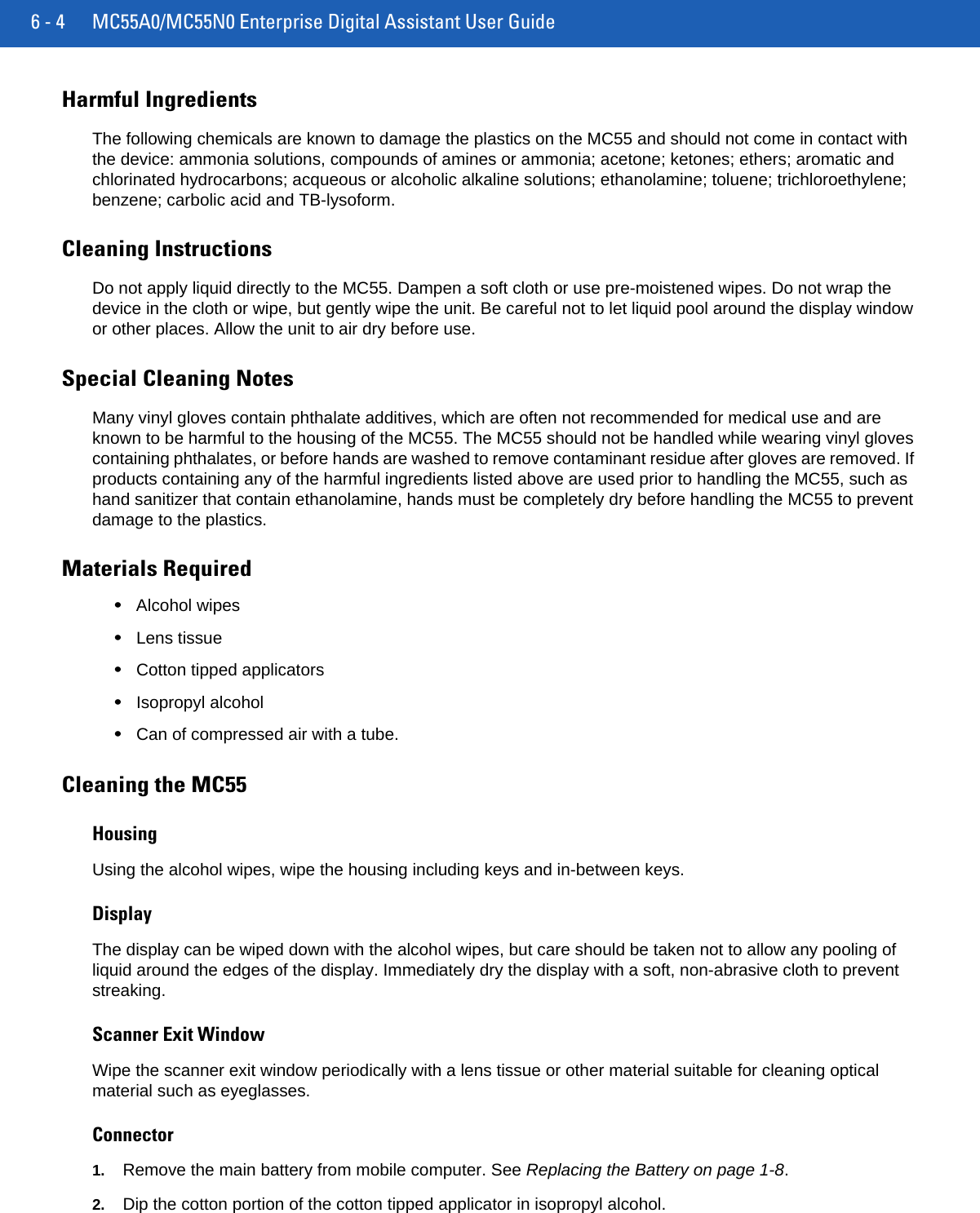

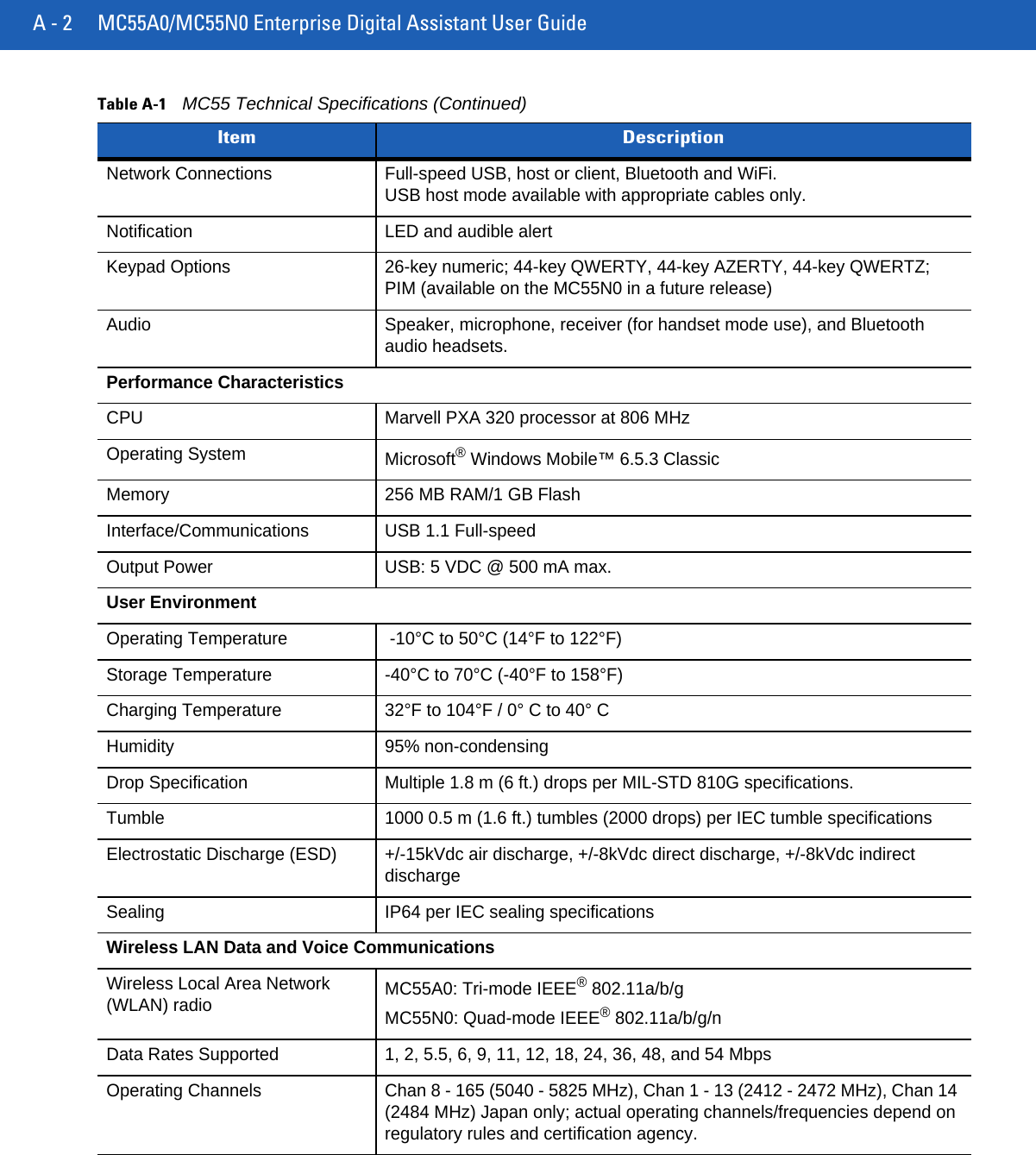

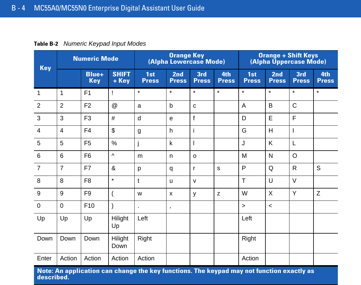
![B - 2 MC55A0/MC55N0 Enterprise Digital Assistant User GuideTable B-1MC55 Numeric Keypad Descriptions Key DescriptionBlue KeyUse this key to launch applications or access items (shown on the keypad in blue).Press the Blue key once to activate this mode, followed by another key.A single press illuminates the key and displays the following icon at the bottom of the screen, until a second key is pressed:Orange KeyUse this key to access the secondary layer of characters and actions (shown on the keypad in orange). Press the Orange key once to lock the keypad into Alpha state. A single press illuminates the key and displays the following icon at the bottom of the screen:Press the Orange key a second time to return to the normal state.Press the Orange key, then the Shift key to add a temporary shift (that applies only to the next key pressed) to the orange lock state. This displays the following icon at the bottom of the screen:Talk/Start Menu Use this key in conjunction with the Blue key to instantly display the Start menu from any application without tapping the screen. This function is user programmable.To use a key as an application key (APP key) on the keyboard, create and install a new keyboard remap table. However, to remap the green phone key as APP keys through the registry, create an XML provisioning file that includes the following entry:<characteristic type=”HKLM\Hardware\DeviceMap\KYBD”><parm name=”GreenKeyOverride” value=”xx” datatype=”integer” /> [where xx is the new APP key code]Provision the file to the MC55 to send an APP key code, instead of the original key code, upon pressing the green phone key. Refer to the MC55A0/MC55N0 Integrator Guide for information on creating XML provisioning files.Scan (yellow)Activates the scanner/imager in a scan enabled application. End/OK Use this key in conjunction with the Blue key as an OK or close button. This function is user programmable.To use a key as an application key (APP key) on the keyboard, create and install a new keyboard remap table. However, to remap the red phone keys as APP keys through the registry, create an XML provisioning file that includes the following entry:<characteristic type=”HKLM\Hardware\DeviceMap\KYBD”><parm name=”RedKeyOverride” value=”yy” datatype=”integer” /> [where yy is the new APP key code]Provision the file to the MC55 to send an APP key code, instead of the original key code, upon pressing the red phone key. Refer to the MC55A0/MC55N0 Integrator Guide for information on creating XML provisioning files.](https://usermanual.wiki/Zebra-Technologies/MC55N0.REVISED-USER-MANUAL-6/User-Guide-1556666-Page-30.png)
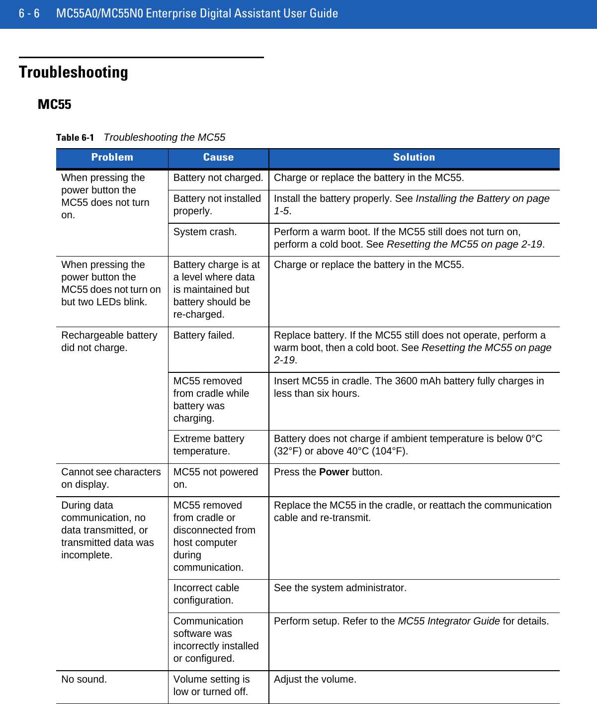
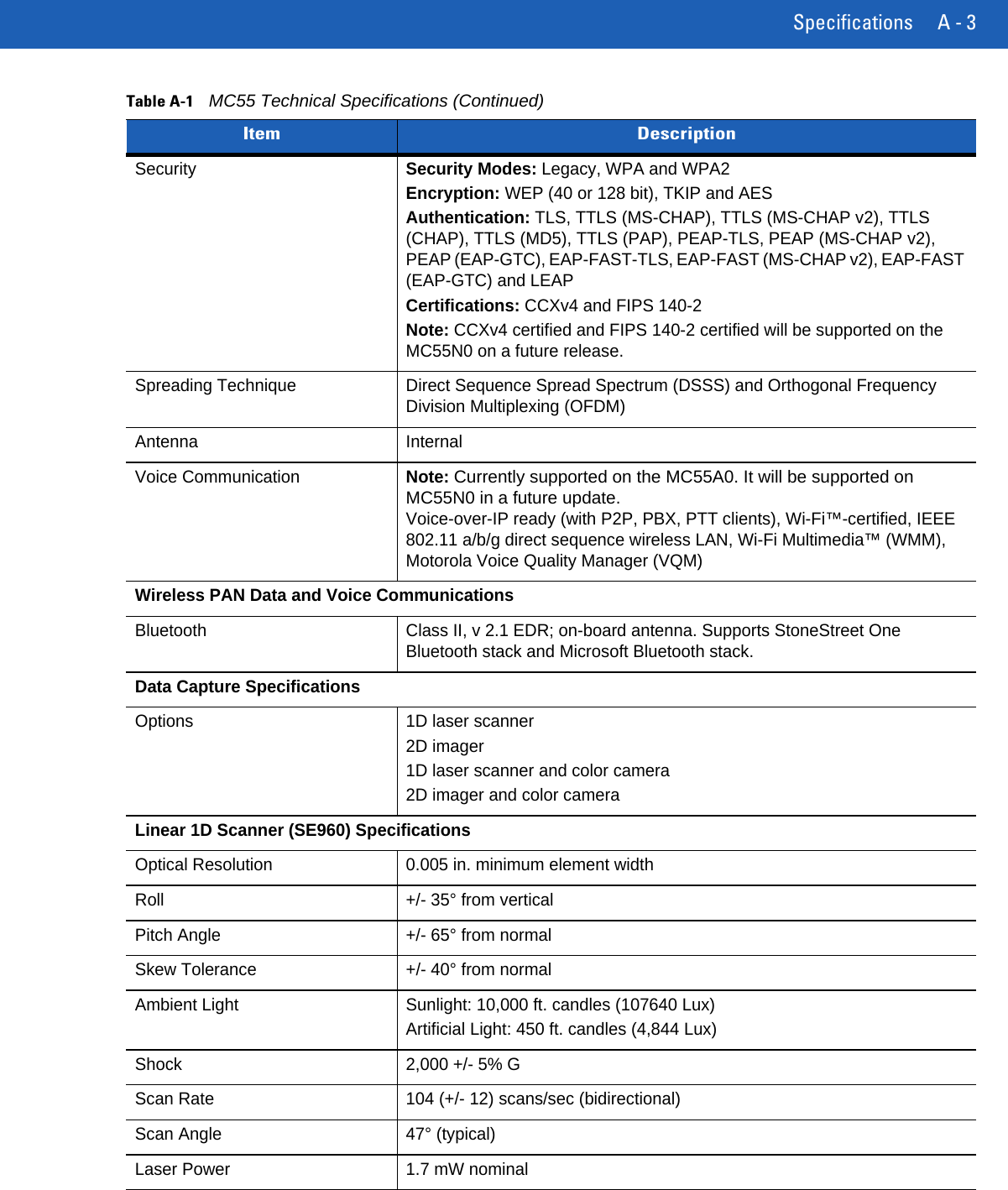
![B - 6 MC55A0/MC55N0 Enterprise Digital Assistant User GuideFigure B-4QWERTZ Keypad ConfigurationTable B-3Alpha-numeric Keypad Descriptions Key ActionBlue Key Press and release the Blue key once to activate this mode temporarily, followed by another key. This displays the following icon at the bottom of the screen, until a second key is pressed:Press and release the Blue key twice to lock this mode. This displays the following icon at the bottom of the screen:Press and release the Blue key a third time to unlock.Orange Key Accesses the secondary layer of characters and actions (shown on the keypad in orange).Press and release the Orange key once to activate this mode temporarily, followed by another key. This displays the following icon at the bottom of the screen, until a second key is pressed:Press and release the Orange key twice to lock this mode. This displays the following icon at the bottom of the screen:Press and release the Orange key a third time to unlock.Talk/Start Menu Use this key in conjunction with the Blue key to instantly display the Start menu from any application without tapping the screen. This function is user programmable.To use a key as an application key (APP key) on the keyboard, create and install a new keyboard remap table. However, to remap the green phone key as APP keys through the registry, create an XML provisioning file that includes the following entry:<characteristic type=”HKLM\Hardware\DeviceMap\KYBD”><parm name=”GreenKeyOverride” value=”xx” datatype=”integer” /> [where xx is the new APP key code]Provision the file to the MC55 to send an APP key code, instead of the original key code, upon pressing the green phone key. Refer to the MC55A0/MC55N0 Integrator Guide for information on creating XML provisioning files.ok](https://usermanual.wiki/Zebra-Technologies/MC55N0.REVISED-USER-MANUAL-6/User-Guide-1556666-Page-34.png)