Zebra Technologies P430I Plastic Card Printer User Manual P430i UM
Zebra Technologies Corporation Plastic Card Printer P430i UM
Contents
- 1. Users Manual part 1
- 2. Users Manual part 2
- 3. Users Manual part 3
Users Manual part 3
34 P430
i
User’s Manual 980471-001 Rev. 01
Cleaning
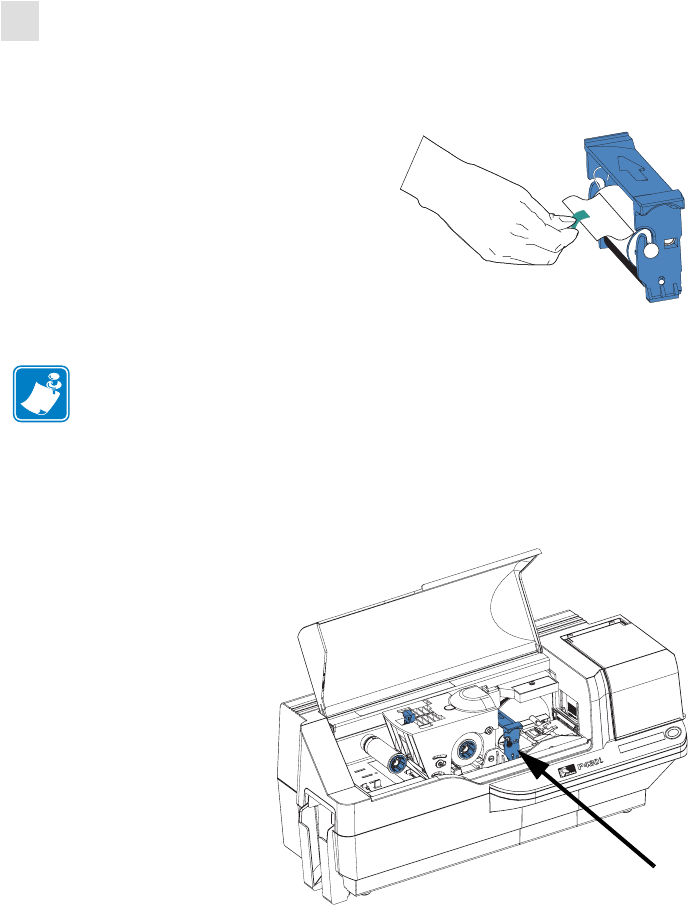
Card Cleaning Cartridge
6. Replace the Card Cleaning Cartridge into the printer. For detailed instructions, see
Installing the Card Cleaning Cartridge on page 14.
7. Close the printer main cover.
Note • DO NOT touch the adhesive roller surface that contacts the cards.
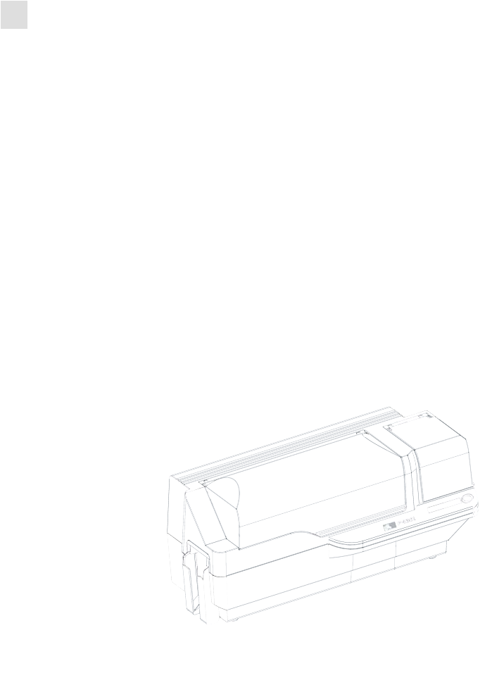
Dual-Sided Color
Card Cleaning
Cartridge in final
position

980471-001 Rev. 01 P430
i
User’s Manual 35
5
Troubleshooting
The table on the next page offers causes and solutions to symptoms related to improper
operation. Check the table when experiencing any loss of operation or print quality.

36 P430
i
User’s Manual 980471-001 Rev. 01
Troubleshooting
Problem / Description Cause / Solution
The LCD Panel displays OUT
OF CARDS message.
1. Check for cards in the card
feeder. If no cards present, load
cards.
2. Check that Card Thickness
Control lever is properly adjusted
(see Loading Cards in Chapter 2).
3. Press the Panel Button for 1
second. The printing job will
restart.
The LCD Panel displays OUT
OF RIBBON message.
1. Check ribbon. Replace if
defective or entirely used.
Ribbon will automatically
synchronize and printing will
restart with a new card.
The LCD Panel displays PRINT
HEAD OPEN message.
1. Check that Print Head Carriage
is closed and latched. If not, close
and latch it.
The LCD Panel displays
MECHANICAL ERROR
message.
1. Check that you are using the
correct card type (see Technical
Specifications).
2. Check that Card Thickness
Control lever is properly adjusted
(see Loading Cards in Chapter 2).
3. If 2 cards are fed into the
printer at the same time:
Open cover and remove Card
Cleaning Cartridge, empty the
Card Feeder, and pull the jammed
cards out. Replace the Card
Cleaning Cartridge.
Remove cards from Card Feeder,
separate them as shown in
Loading Cards in Chapter 2, and
replace.
4. Check that ribbon is loaded
correctly.
The LCD Panel displays
ENCODING ERROR message.
1. Check that you are using the
correct magnetic card type (for
low or high coercivity encoding).
2. Verify command syntax.
3. Contact Zebra technical
support.
The LCD Panel displays
CLEAN PRINTER message.
1. Printer cleaning required (see
Chapter 4).
Troubleshooting
Print Quality Issues
980471-001 Rev. 01 P430
i
User’s Manual 37
Print Quality Issues
This section will help you resolve print quality problems. The print quality is dependent on
several factors. The two most important factors that will increase your print quality are
cleanliness and card stock. To diagnose and fix print quality problems, follow the
troubleshooting procedures below:
Possible Cause:
• Contamination on the card surface.
Solutions:
• Check that cards are stored in a dust free environment.
• Use a different supply of cards.
Possible Cause:
• Dust inside the printer and/or dirty Cleaning Roller.
Solutions:
• Perform a Cleaning of the printer (see Chapter 4).
• Replace Cleaning Roller (see Chapter 4).
Possible Cause:
• Ribbon cartridge is not correctly positioned.
Solutions:
• Ensure that the ribbon is properly rolled onto the ribbon cores of the cartridge and that
there are no wrinkles in the ribbon.
• Replace ribbon cassette, making sure it locks in place.
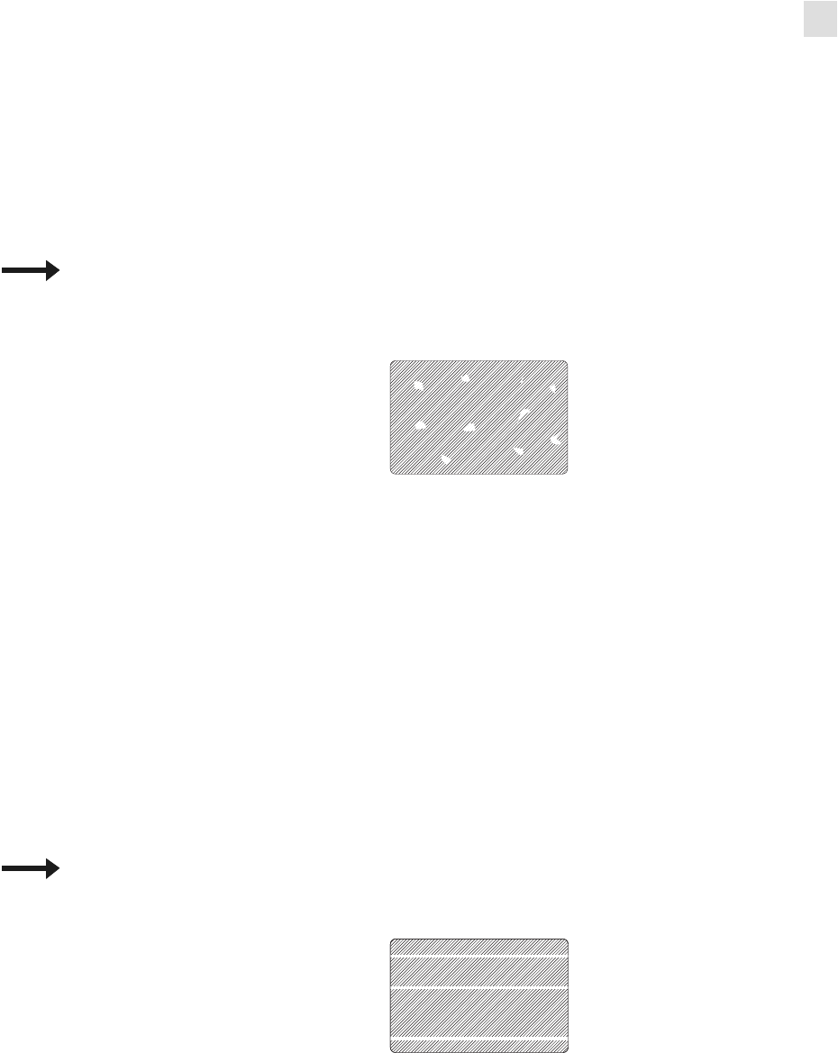
Example 1 • Small spots appear on the printed card with a non-printed area or a different
color.
Example 2 • There are non-printing horizontal lines (white) on the card surfaces.
38 P430
i
User’s Manual 980471-001 Rev. 01
Troubleshooting
Print Quality Issues
Possible Cause:
• Print Head is dirty.
Solution:
• Clean the Print Head
Possible Cause:
• Print Head elements are damaged (e.g., scratched or burnt).
Solution:
• Call Zebra Customer Service for Print Head replacement information.
Possible Cause:
• Ribbon has been stored improperly or is damaged.
Solution:
• Change ribbon and print again.
Possible Cause:
• Cards may not meet specifications.
Solution:
• Use a different supply of cards.
Possible Cause:
• Contrast and/or Intensity may be set to incorrect values.
Solution:
• Adjust Contrast and/or Intensity values in software.
Possible Cause:
• Head Settings are too low / high.
Solution:
• Adjust Head Settings higher / lower.
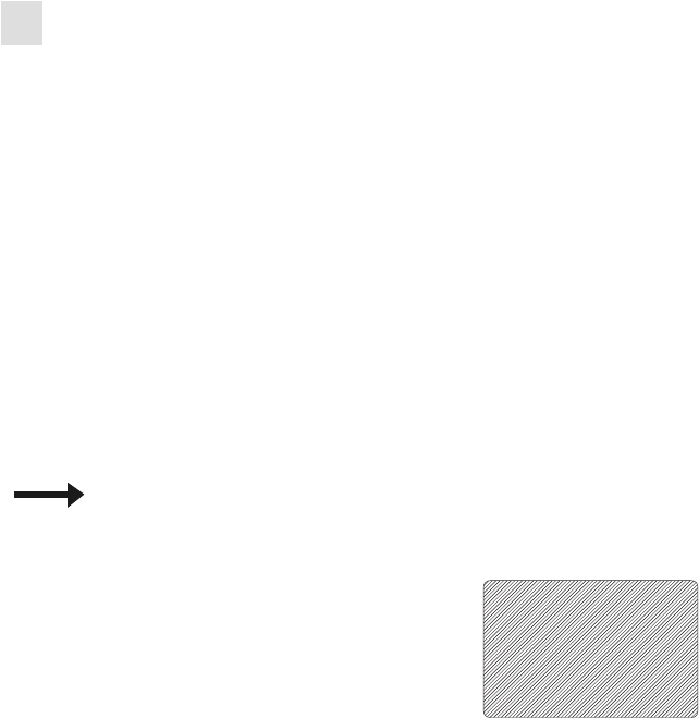
Example 3 • Printing shows very pale, very dark, or inconsistent results

Troubleshooting
Print Quality Issues
980471-001 Rev. 01 P430
i
User’s Manual 39
Possible Cause:
• Dust or embedded contamination on elements of the Print Head.
Solution:
• Perform a Cleaning of the Print Head (see Chapter 4).
Possible Cause:
• Ribbon cartridge may not be correctly positioned.
Solution:
• Check that the ribbon is properly rolled onto the ribbon cores of the cartridge.
• Replace ribbon cartridge, making sure it locks in place, and print again.
Possible Cause:
• Ribbon may not be synchronized on the correct color panel position.
Solution:
• Open the Print Head Carriage, then close it. This will cause the ribbon to re-
synchronize.
Possible Cause:
• Cards may not meet specifications.
Solution:
• Use a different supply of cards.
Possible Cause:
• Dust or embedded contamination inside the printer and/or dirty Cleaning Roller.
Solution:
• Clean the Print Head.
• Replace the Cleaning Roller.
Example 4 • Printing shows blurry printed image.

40 P430
i
User’s Manual 980471-001 Rev. 01
Troubleshooting
Print Quality Issues
Possible Cause
• Ribbon may not be installed in the printer.
Solution:
• Check for ribbon in the printer.
Possible Cause
• Cards may not meet specifications.
Solution:
• Use a different supply of cards.
Possible Cause
• Print Head elements may be scratched or burnt.
Solution
• Call Service for Print Head replacement information.
Possible Cause
• Using the wrong type of ribbon.
Solution:
•Use only i Series ribbons for full color printing.
Example 5 • No printing on the card.
Example 6 • Only one panel of a color ribbon prints.
Note • For optimum print quality, always keep the Main Cover and the Card Feeder Cover of
the printer closed.

Troubleshooting
Troubleshooting the Ethernet Connection and Adapter
980471-001 Rev. 01 P430
i
User’s Manual 41
Troubleshooting the Ethernet Connection and Adapter
Resetting to Factory Defaults
To reset the Ethernet Adapter configuration parameters to the factory defaults, press the Panel
Button and hold it in while turning the printer power on. Keep the Panel Button pressed until
the Status Indicator light turns green, then release the Panel Button. To print a configuration
card, press and hold the Ethernet switch.
Ethernet Adapter Status Indicator
A bi-color Status Indicator displays the operational status of the Ethernet Adapter.The
following conditions might occur:
1. During normal operation, the LED is solid green for more than 30 seconds. This indicates
all the hardware is functioning properly and the Ethernet Adapter has detected the
presence of the network. It does not mean the Ethernet Adapter has an IP address or is
attached to a printer queue.
2. If the LED is rapidly flashing green (9 times/sec), the Ethernet Adapter has not detected
the presence of a network cable. To solve the problem:
• Verify that the network cable is appropriate for the network and has an RJ-45
connector.
• Turn the printer power off (O). Remove the network cable from the Ethernet Adapter.
Plug the network cable back in until you hear a positive click. Check the other end of
the cable in the same manner. Turn the printer power on; if the Ethernet Adapter still
does not detect a cable, continue.
• Connect the Ethernet Adapter to a known good network connection. If the Ethernet
Adapter is still unable to detect the network cable, contact Technical Support for
assistance.
3. If the LED is slowly flashing green (1 time/sec), the Ethernet Adapter is trying to print a
job. If the job does not print, check the following:
• Verify that the printer has media and ribbon. If the printer is showing any errors, it is
unlikely that the Ethernet Adapter can send data to the printer. The LED continues to
blink until the printer malfunction is resolved or until the printer is turned off (O).
• Flashing red indicates the Power On Self Test (POST) is in progress.
4. If the LED is solid red for more than 30 seconds, the Ethernet Adapter has failed the
POST. A failed POST can be caused by any of the following:
• The printer attached to the Ethernet Adapter device is malfunctioning. Turn the
printer power off, wait 10 seconds, then turn the printer back on ( | ).
• If the Ethernet Adapter still fails the POST, the Ethernet Adapter has a hardware
problem that can be fixed only by replacing or returning the unit. Contact Technical
Support for repair or replacement information.
Important • Cables with a rating higher than CAT-6 have not been tested.

42 P430
i
User’s Manual 980471-001 Rev. 01
Troubleshooting
Troubleshooting the Ethernet Connection and Adapter
5. If the LED is alternately flashing red and green for longer than 2 minutes, the Ethernet
Adapter is in firmware-download mode. This means it is waiting for new firmware data to
be sent before it continues normal functioning. Perform the following:
• If the Ethernet Adapter was purposely put into firmware-download mode, finish the
download with the proper update utility. Contact the Zebra web site at
http://www.zebra.com to download this utility.
• Contact Technical Support for help recovering this unit.
Network Status/Activity Indicator
A bi-color Status/Activity LED indicates network speed, established link, and network
activity.
1. If the LED is off, no link was established.
2. If the LED is solid green, a 100Base link is established.
3. If the LED is flashing green, a 100Base link is established and network activity has been
detected.
4. If the LED is solid orange, a 10Base link is established.
5. If the LED is flashing orange, a 10Base link was established and network activity has
been detected.
Network activity detected by this LED does not mean the activity is data for the print server.
The activity is all activity on the network seen on the Ethernet Adapter.

980471-001 Rev. 01 P430
i
User’s Manual 43
6
Technical Specifications
General Specifications
• Full color dye-sublimation card printing
• 25 seconds per card single-sided color printing (YMCKO)
• Monochrome thermal transfer printing
• 4 seconds per card monochrome
Ribbon Specifications
• Patented ribbon core and spindle system
•i Series technology featuring RFID
Card Specifications
• Types: PVC or Composite
• Card Width/length ISO CR-80 - ISO 7810, 2.125" (54 mm) x 3.375" (86 mm)
• Option: Magnetic Stripe - ISO 7811
• Card thickness: 10-60 mil (0.25-1.5 mm) ± 10%
• Card feeder capacity: up to 100 cards (30mil) (Optional high-capacity feeder: up to 220 cards)
• Reject card hopper capacity: 20 cards (30 mil)
• Card output hopper capacity: 100 cards (30mil)
Note • "i Series" Printers require the use of "i Series" ribbons for full color printing. For
more information about Card Media and Ribbons available from Zebra Technologies Corp.,
please refer to the Media List on the Windows Drivers and User Documentation CD supplied
with this printer.
44 P430
i
User’s Manual 980471-001 Rev. 01
Technical Specifications
Bar Codes
Bar Codes
• Code 39, Code 128 B & C with & without check digit
• 2 of 5 and 2 of 5 interleaved
• UPC-A, EAN8, and EAN13
• PDF-417 2D bar code and other symbologies available via Windows printer driver
Fonts
• Arial and Arial Bold
• True Type fonts available via Windows Driver
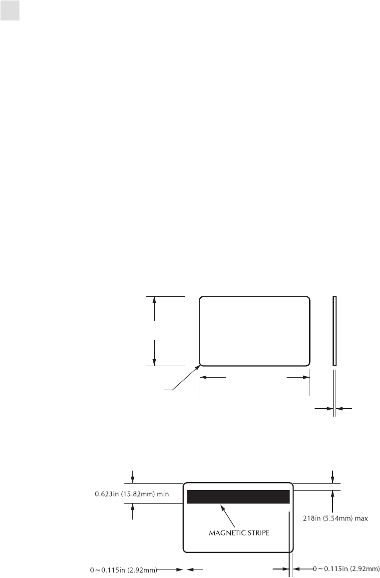
Card Dimensions
ISO Standard 7810 Dimensions for Plain Card
ISO Standard 7811 Dimensions for Magnetic Stripe Card
0.125 in
Radius
(3.18 mm)
3.375 ± 0.01 in
(85.72 ± 0.25 mm)
2.125 ± 0.002 in
(53.98 ± 0.050 mm)
0.009 ~ 0.034 in
(0.23 ~ 0.84 mm)

Technical Specifications
Bi-Directional Communications Interfaces
980471-001 Rev. 01 P430
i
User’s Manual 45
Contact Location for Smart Card ISO Standard 7816
Bi-Directional Communications Interfaces
•USB
• Built-in Ethernet (optional)
Mechanical Specifications
• Width: 18.2 in (462 mm)
• Depth: 9.4 in (239 mm)
• Height: 10.1 in (256 mm)
• Weight: 15.5 lbs (7 kg)
Electrical
• 110 ~ 230 Volts AC ± 10% (99 - 254 V), 60 ~ 50 Hz ± 3Hz (47 - 63 Hz)
• FCC Class B, CE, UL, and CUL approved
Environmental
• Operating Temperature: 60°F to 86°F (15°C to 30°C)
• Operating Humidity: 20% to 65% non condensing
• Storage Temperature: 23°F to 158°F (-5°C to 70°C)
• Storage Humidity: 20% to 70% non-condensing
• Ventilation: Reasonably dust free air environment
Options
• Built-in Ethernet network communications
• Three track magnetic stripe encoder (standard and reverse)
• High capacity feeder (220 30-mil cards)
• Contactless encoding (MIFARE and HID iCLASS)
• Contact encoding (Station and encoder)
0.403 in (10.25 mm)
0.782 in (19.87 mm)
0
.
757
i
n
(19.23 mm) 1.124 in
(28.55 mm)
ISO 7816 Cards
46 P430
i
User’s Manual 980471-001 Rev. 01
Technical Specifications
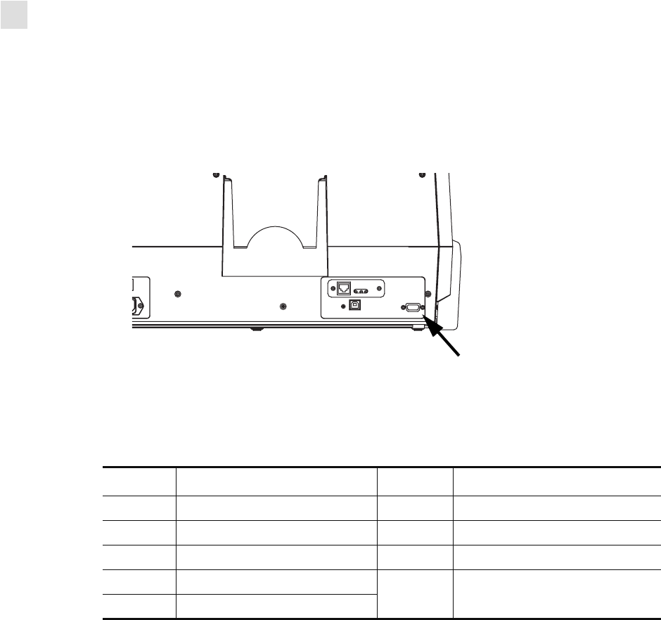
Options
Dual-Sided Color

980471-001 Rev. 01 P430
i
User’s Manual 47
APPENDIX A
Introduction
This Appendix includes operation and maintenance requirements for the P430i Printer with the
optional magnetic card stripe encoder. (See Chapter 2 for location of the Magnetic Card Stripe
Encoder.)
The magnetic encoder can be set for either high or low coercivity. Use the printer driver to
change the encoder setting.
Media Loading Orientation
The magnetic encoder may be installed with the read/write head positioned below the card
path. Magnetic Card Stripe Encoder upgrade kits are also available.
When loading cards with magnetic stripes into the card feeder, please ensure that the magnetic
stripe is down and nearer to the rear of the printer.
Also available are Printer models with the Magnetic Read/Write head positioned above the
card path. When loading cards into one of these models, ensure that the magnetic stripe is up
and nearer to the rear of the printer.
Magnetic Card
Stripe Encoder

48 P430
i
User’s Manual 980471-001 Rev. 01
Magnetic Card Stripe Encoder
Sample Encoding Program
Sample Encoding Program
Refer to the Programmer’s Manual (part number 98001-001).
Magnetic Encoder Cleaning
The Magnetic Encoder Read/Write Head is cleaned as part of the printer cleaning process. If
the frequency of encoding errors increases, the magnetic encoder head may need cleaning.
When to Clean
When the LCD Panel displays the message ENCODING ERROR at an increasing frequency.
How to Clean
1. Leave power on.
2. Press and hold the front panel button for a few seconds.
3. Open the main cover and release the Print Head Carriage latch, raise the Print Head
Carriage, and remove the ribbon. Close the Print Head Carriage.
4. Close the main cover.
5. Open the Card Feeder cover and remove any cards.
6. Insert a Pre-Saturated Cleaning Card (provided) into the slot below the Card Feeder. The
cleaning card will feed into the printer and carry out the cleaning process. Repeat the
process with a new cleaning card if necessary.
7. Additional cleaning of the magnetic head can be accomplished using the alcohol-soaked
swabs provided with the printer. Follow the directions given in Section 4.
Note • ONLY USE cards that comply with ISO 7810 and 7811 standards for magnetic stripe
cards. The magnetic stripe must be flush to the surface of the card to work properly. Never
use cards which have taped-on magnetic stripes.
Magnetic Card Stripe Encoder
ISO Standard Encoding
980471-001 Rev. 01 P430
i
User’s Manual 49
ISO Standard Encoding
Track # Field
Separator
Track
Density
Valid
Characters
# of
characters
1 ^ 210 BPI* Alphanumeric
(ASCII 20~95†)
79‡
2 = 75 BPI* Numeric
(ASCII 48~62)
40‡
3 = 210 BPI* Numeric
(ASCII 48~62)
107‡
*Bits per inch
†Except the “?” character
‡Including Start, Stop, and LRC characters. Also note that these 3 characters are
automatically managed by the magnetic encoder according to the ISO Standard
Norms.
Note • Refer to the Card Printer Programmer’s Manual for complete programming
information.
50 P430
i
User’s Manual 980471-001 Rev. 01
Magnetic Card Stripe Encoder
ISO Standard Encoding
Dual-Sided Color

980471-001 Rev. 01 P430
i
User’s Manual 51
APPENDIX B
This section contains information on the additional operations of a P430i Printer equipped
with the optional Smart Card Contact Station. (See Chapter 2 for location.)
Introduction
Smart Cards can have a built-in microcomputer and/or memory to store fingerprints, voice
recognition patterns, medical records, and other such data. The P430i Printer may be equipped
with an optional contact station for programming Smart Cards (ISO 7816). This printer model
responds to commands that position the card at the contact station, where the printer connects
to the contacts on the Smart Card. All other printer operations remain the same as the standard
P430i model.
Media Loading Orientation
Orient the cards with the gold-plated Smart Card contacts at the top surface of the card and
facing to the left.
Smart Card
Contact Station
52 P430
i
User’s Manual 980471-001 Rev. 01
Smart Card Contact Station
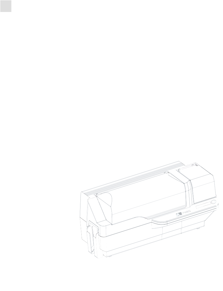
Smart Card Contact Station Interface
Smart Card Contact Station Interface
When a command to the printer interface sends a card to the Smart Card Contact Station, the
printer connects the Smart Card Contact Station to the female DB-9 connector on the rear of
the printer.
An attached external Smart Card Programmer can be used to program Smart Card chips. The
following table shows the Smart Card Contact Points.
DB-9 Pin Smart Card Contact Points DB-9 Pin Smart Card Contact Points
1C1 (VCC) 6 C6 (Vpp)
2C2 (Reset) 7 C7 (I/O)
3C3 (Clock) 8 C8 (RFU)
4C4 (RFU)
9 (GND when chip is at station)
5C5 (GND)
DB-9 Connector location for
Smart Card Contact Station
980471-001 Rev. 01 P430
i
User’s Manual 53
APPENDIX C
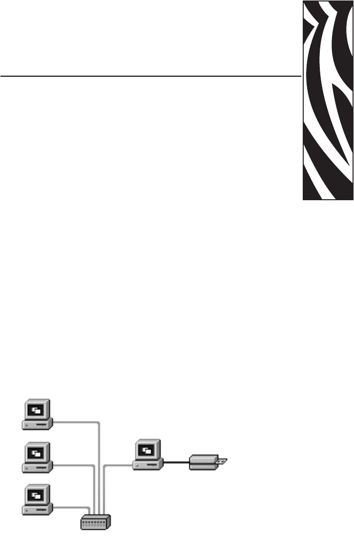
Card printers can be connected to an Ethernet network in three ways.
Printer Sharing
In printer sharing, the printer is connected locally to the host computer and configured to be
shared to other client computers. Client computers connect to the printer over the network
through the host computer.
Connecting to a
Network
54 P430
i
User’s Manual 980471-001 Rev. 01
Connecting to a Network
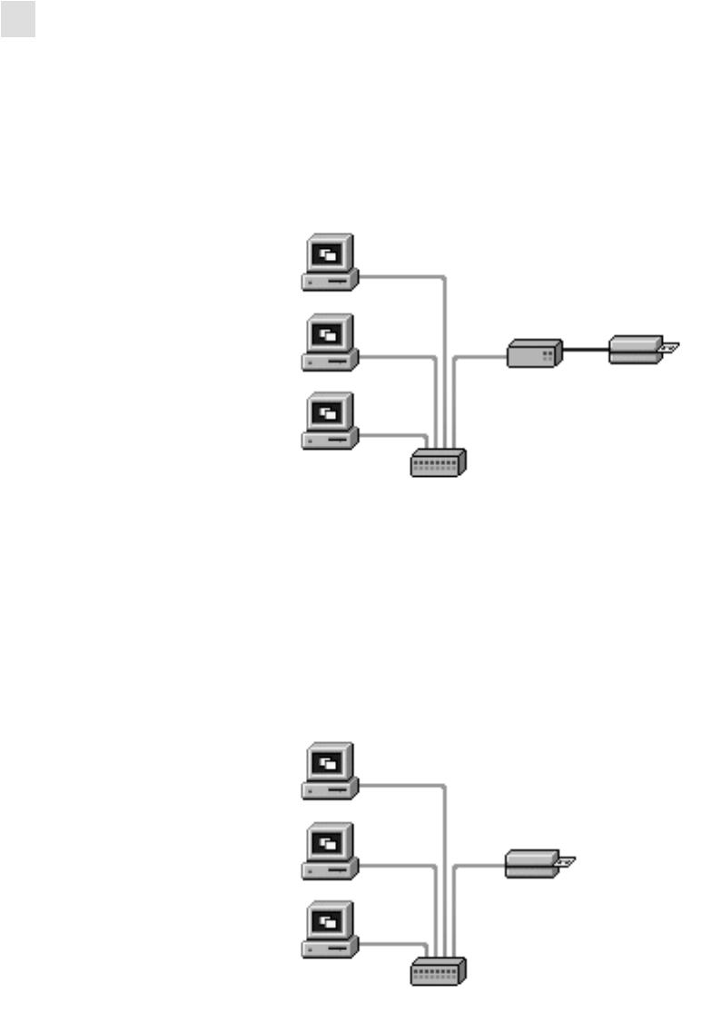
External Print Server
External Print Server
A stand alone device that acts as a server on the network specifically for receiving print jobs
and passing them to the printer. Client computers connect to the print server over a network.
Internal Print Server
Similar to an external print server, except the print server is integrated into the printer. This
removes the need for a separate power supply and separate device drivers. This is the simplest
way to network a printer.

980459-001 Rev. 1 10/15/2004 P330
i
User’s Manual 63
EAPPENDIX D
Sales and Support Locations
Zebra Technologies
Card Imaging Division
1001 Flynn Road
Camarillo, CA 93012-8706 USA
Phone: + 1 (805) 579 1800
Fax: + 1 (805) 579 1808
Toll free in US: (800) 452-4056
e-mail: cards@zebra.com
Zebra Technologies
Card Imaging Division, Europe, Middle East, Africa
The Valley Centre, Gordon Road, High Wycombe
Buckinghamshire HP13 6EQ, England
Phone: + 44 (0) 870 241 1527
Fax: + 44 (0) 870 241 0765
e-mail: eurosales@zebra.com
Zebra Technologies
Card Imaging Division, Latin America
9800 NW 41st Street, Suite 220
Doral, FL 33178 USA
Phone: + 1 (305) 558 8470
Fax: + 1 (305) 558-8485
e-mail: latinsales@card.com
Worldwide Sales &
Support

64 P330
i
User’s Manual 980459-001 Rev. 1 10/15/2004
Worldwide Sales & Support
Corporate Headquarters
Zebra Technologies
Card Imaging Division, Asia/Pacifique
1 Sims Lane # 06-11
387355 Singapore
Phone: + 65 84 20 322
Fax: + 65 84 20 514
e-mail: asiasales@zebra.com
Corporate Headquarters
Zebra Technologies Corporation
333 Corporate Woods Parkway
Vernon Hills, IL 60061-3109 USA
Phone: + 1 (847) 634 6700
Fax: + 1 (847) 913 8766
e-mail: sales@zebra.com
Website
www.zebracard.com