Zebra Technologies R2844Z Thermal Printer with RFID User Manual Pt 2
Zebra Technologies Corporation Thermal Printer with RFID Users Manual Pt 2
Contents
Users Manual Pt 2

Getting Started
This section describes how to set up your printer for the first time and use
the most common operating procedures for loading media in tear-off mode
and loading ribbon.
Modes of Printing
You can operate this printer in different modes:
■Standard tear-off mode allows you to tear off each label (or a strip of
labels) after it is printed.
■In optional peel-off mode, the backing material is peeled away from the
label as it is printed. After this label is removed, the next one is printed.
■In optional cutter mode, an attached unit cuts through the media.
The printer typically uses roll media, but you can use fan-fold or other
continuous media as well.
For procedures to use optional modes and features, refer to the Operation
and Options section.
980476-001A 7
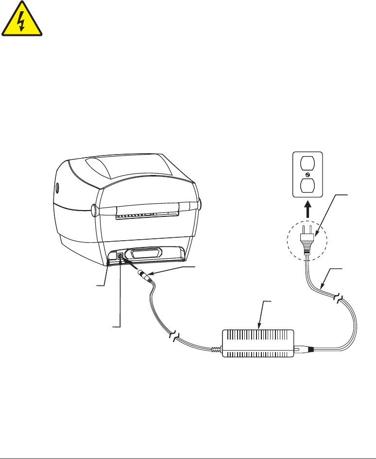
Attaching Power Supply
Check the power supply to make certain it is appropriate for your input
voltage.
Caution • Use the power supply that came with your printer. Never operate the
printer and power supply in an area where they can get wet. Serious personal injury
could result!
1. Make sure the power switch is in the off position (down).
2. The DC power supply has a barrel connector on one end that must be
inserted into the power supply receptacle on the back of the printer.
3. Insert the separate AC power cord into the power supply.
4. Plug the other end of the cord into an appropriate AC electrical outlet.
8 980476-001A
Plug
Varies b
y
Country
AC
Power
Cord
Power
Supply
Power
Switch
Power
Supply
Receptacle
Barrel
Connector
Loading Roll Media
When you load media, you must place the roll on the media hangers and
then adjust the media guides.
You must use the correct media for the type of printing you require. When
printing without a ribbon, you must use direct thermal media. When using
ribbon, you must use thermal transfer media. The printer's ribbon sensor
detects motion of the supply spindle.
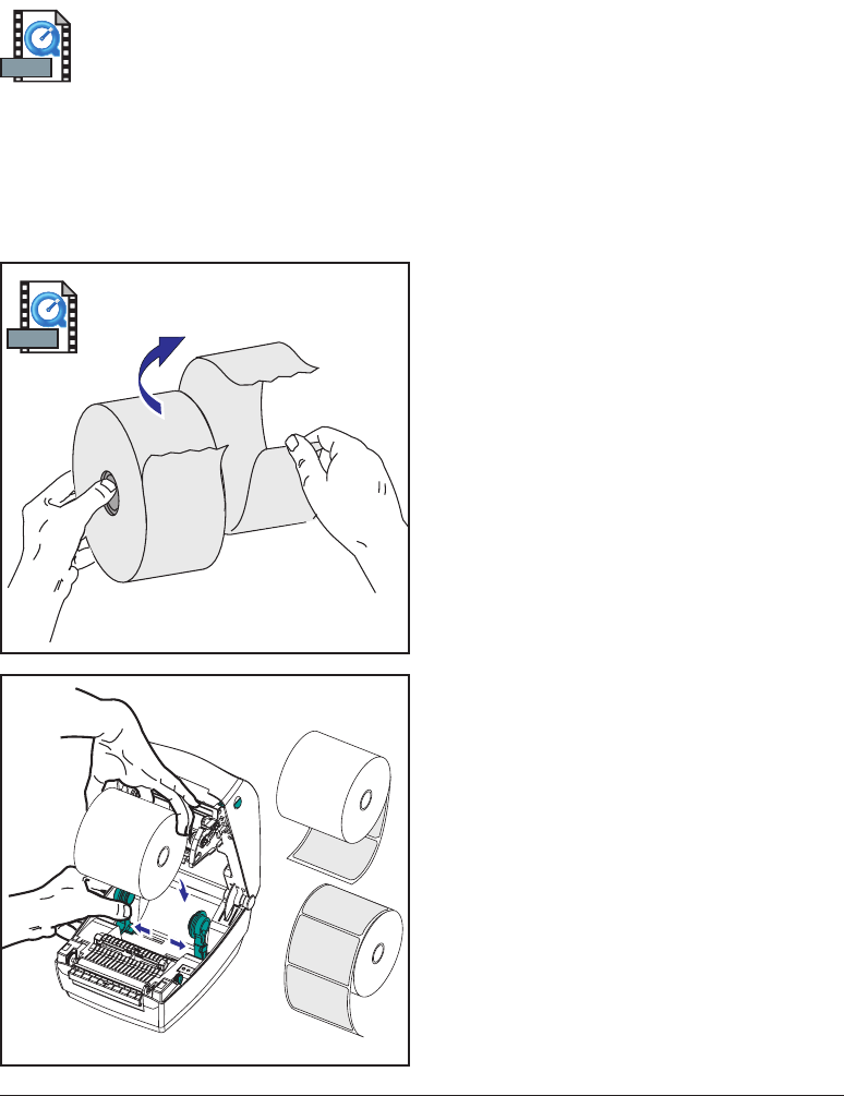
Placing the Roll in the Media Compartment
Whether your roll media is inside or
outside wound you load it into the printer
the same way.
1. Open the printer. Remember that you
need to pull the release levers toward
the front of the printer.
2. Remove the outside length of media.
During shipment, the roll may become
dirty when handled or dusty when
stored. Removing the outside length
avoids dragging adhesive or dirty
media between the print head and
platen.
3. Separate and hold open the media
hangers.
4. Orient the media roll so that its
printing surface will be up as it passes
over the platen.
5. Lower the roll between the hangers
and close them onto the core.
980476-001A 9
MOVIE
MOVIE
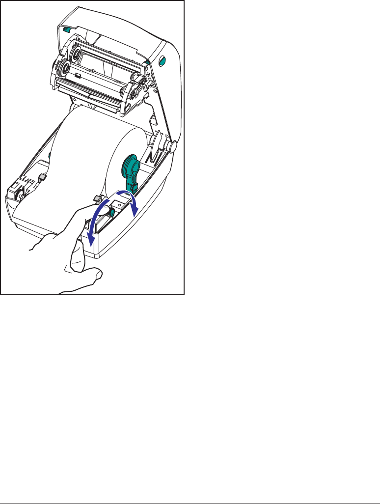
Adjusting the Guides
The adjustable guides direct the media
toward the platen and print head.
1. Open the media guides by turning the
guide adjuster knob to the rear.
2. Thread the media through the guides.
3. Close the media guides by turning the
guide adjuster knob to the front. They
should just touch, but not restrict, the
edges of the media.
4. Unless you need to load ribbon, close
the top cover. Remember that you
need to release the cover lock, lower
the top cover, and press down until the
latches snap into place.
10 980476-001A
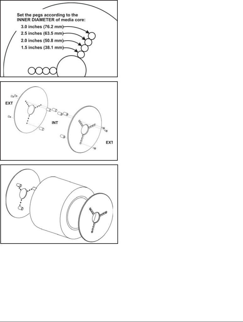
Using the Optional Media Adapter Plates
If your media roll has a larger diameter
core, you can use an accessory to adapt
the core to the media holders.
1. Note which position will fit the
diameter of the roll core.
2. On the left side plate, align the pegs
with the screws and use a small
Phillips driver to tighten them.
3. On the right side plate, align the pegs
with the screws and use a small
Phillips driver to tighten them.
4. Align the plates so that the pegs hold
the roll core and press together.
5. Place the roll into the media
compartment.
980476-001A 11
Loading Ribbon
You must use thermal transfer media (accepts wax and/or resin transferred
off a ribbon) when you use a ribbon. When loading ribbon, you install the
supply and take-up rolls, then tighten the ribbon on the carriage.
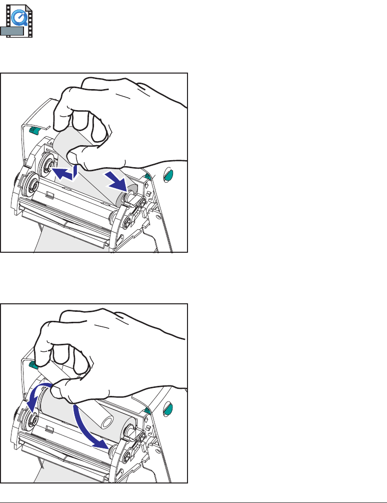
Install the Ribbon Supply Roll
Before following these steps, prepare the
ribbon by removing its wrapping and
pulling its adhesive strip free.
1. Thread the ribbon through the
carriage.
2. Press the right side onto the supply
hub.
3. Align the notches on the left side and
mount onto the spokes of the left hub.
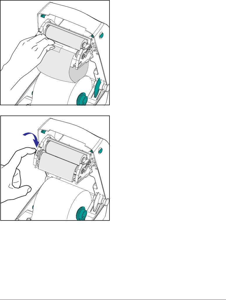
Install the Take-Up Core
1. Press the right side onto the take-up
hub.
2. Align the notches on the left side and
mount onto the spokes of the left hub.
You can find your first ribbon take-up
core in the packing box. Subsequently,
use the empty supply core to take up the
next roll of ribbon.
12 980476-001A
MOVIE
Attach and Tighten the Ribbon
You must align the ribbon so that it will
be taken straight onto the core.
1. Attach the ribbon to the take up core.
Use the adhesive strip on new rolls;
otherwise, use tape.
2. Turn the ribbon take-up gear
counter-clockwise (top moves toward
rear) to remove slack from the ribbon.
3. Close the top cover. Remember that
you need to release the cover lock,
lower the top cover, and press down
until the latches snap into place.
980476-001A 13
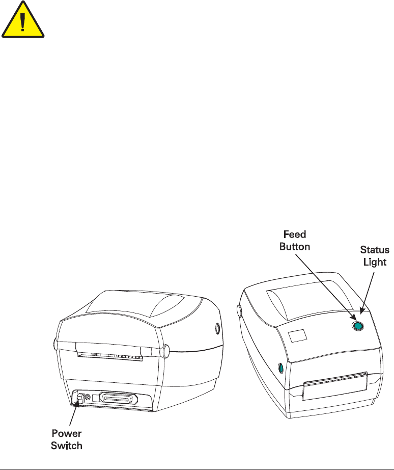
Operator Controls
Power Switch
Press up to turn ON or down to turn OFF the printer.
CAUTION • The power should be turned off before connecting or disconnecting the
communications and power cables.
Feed Button
Press once to feed one blank label.
Press once to take the printer out of a “pause” condition. (The printer is put
into “pause” by either a programming command or an error condition.) See
“What the Status Light is Telling You” on page 61.
Use the Feed button for printer setup and status (see “Feed Button Modes”
on page 70).
Status Light
Functions as a printer operational indicator (see “What the Status Light is
Telling You” on page 61).
14 980476-001A
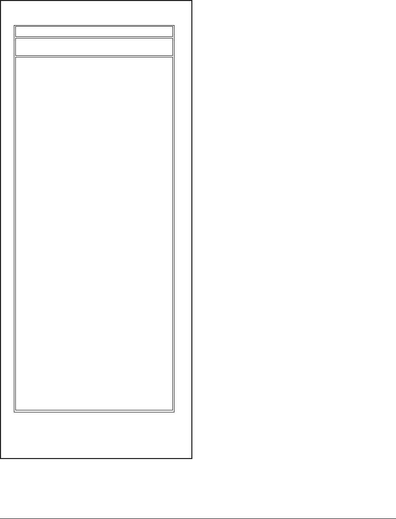
Printing a Test Label
Before you connect the printer to your
computer, make sure that the printer is in
proper working order. You can do this by
printing a configuration label.
1. Make sure the media is properly
loaded and the top cover of the printer
is closed. Then, turn the printer
power on if you have not already done
so.
2. When the status light is solid green,
press and hold the feed button until
the status light flashes once.
3. Release the feed button. A
configuration label will print.
If you cannot get this label to print, refer
to Troubleshooting on page 61.
980476-001A 15
+10 DARKNESS
+000 TEAR OFF
TEAR OFF PRINT MODE
NON-CONTINUOUS MEDIA TYPE
WEB SENSOR TYPE
THERMAL-TRANS. PRINT METHOD
104 0/8 MM PRINT WIDTH
12 LABEL LENGTH
.0IN MM MAXIMUM LENGTH
0 BAUD
8 BITS DATA BITS
NONE PARITY
XON/XOFF HOST HANDSHAKE
NONE PROTOCOL
000 NETWORK ID
NORMAL MODE COMMUNICATIONS
<˜> 7EH CONTROL PREFIX
<^> 5EH FORMAT PREFIX
<,> 2CH DELIMITER CHAR
ZPL II ZPL MODE
MEDIA POWER UP
FEED HEAD CLOSE
DEFAULT BACKFEED
+020 LABEL TOP
+0000 LEFT POSITION
029 WEB S.
068 MEDIA S.
050 RIBBON S.
050 MARK S.
001 MARK MED S.
CS MODES ENABLED
.. MODES DISABLED
832 8/MM FULL RESOLUTION
SP.814.B <- FIRMWARE
V2.2.6.98.C HARDWARE ID
CUSTOMIZED CONFIGURATION
1024.............R: RAM
0768.............E: ONBOARD FLASH
NONE FORMAT CONVERT
NONE OPTION
NONE ZEBRA NET II
400:Ver. 2. RFID VERSION
................
...............
...........
.....
................
.....
.........
48...............
39 988 .....
NOT CONNECTED ...... USM COMM.
PARALLEL........... PARALLEL COMM.
RS232 ............. SERIAL COMM.
860 ...............
.............
...............
...........
...............
................
........
...........
...........
...........
.............
FEED...............
...............
............
...............
..............
................
................
................
................
................
062................ MEDIA LED
000................ RIBBON LED
081................ MARK LED
.................
.................
......
.....
........
.........
...............
................... TWINAX/COAX ID
...............
...............
OEM 4F
Zebra Technologies
ZTC R2844-Z-200dpi
PRINTER CONFIGURATION
FIRMWARE IN THIS PRINTER IS COPYRIGHTED
Hooking Up the Printer and Computer
Your printer will have one of two combinations of interfaces:
■Universal Serial Bus (USB), parallel and serial
■USB, ethernet, and serial
Each specific interface option—USB, parallel, ethernet, serial—is discussed
individually.
You must supply the required interface cable for your application.
CAUTIONS • Keep the power switch in the OFF position when attaching the
interface cable.
The power supply barrel connector must be inserted into the power supply
receptacle on the back of the printer before connecting or disconnecting the
communications cables.
This printer complies with FCC “Rules and Regulations,” Part 15, for Class B
Equipment, using fully shielded six-foot data cables. Use of longer cables or
unshielded cables may increase radiated emissions above the Class B limits.
Interface Cable Requirements
Data cables must be of fully shielded construction and fitted with metal or
metalized connector shells. Shielded cables and connectors are required to
prevent radiation and reception of electrical noise.
To minimize electrical noise pickup in the cable:
Keep data cables as short as possible (6’ [1.83 m] recommended).
Do not tightly bundle the data cables with power cords.
Do not tie the data cables to power wire conduits.
USB Interface Requirements
Universal Serial Bus (version 1.1) provides a high-speed interface that is
compatible with your existing PC hardware. USB’s “plug and play” design
makes installation easy. Multiple printers can share a single USB port/hub.
16 980476-001A
MOVIE

Parallel Interface Requirements
The required cable (IEEE 1284-compliant is recommended) must have a
standard 36-pin parallel connector on one end, which is plugged into the
parallel port located on the back of the printer. The other end of the parallel
interface cable connects to the printer connector at the host computer.
For pinout information, refer to page 72.
Ethernet Interface Requirements
Ethernet provides a powerful networking capability that can be of use in a
variety of internet/intranet printing solutions. After you load media and
close the top cover, you can press the test button next to the connector on
the rear of the printer to get an ethernet configuration label.
Serial Interface Requirements
The required cable must have a nine-pin “D” type (DB-9P) male connector
on one end, which is plugged into the mating (DB-9S) serial port located on
the back of the printer. The other end of this signal interface cable connects
to a serial port at the host computer. Depending on the specific interface
requirements, this will most likely be a null modem cable.
For pinout information, refer to page 74
980476-001A 17

Communicating with the Printer
Universal Serial Bus (USB) Communications
The printer is a terminal device when using a universal serial bus interface.
You can refer to the Universal Serial Bus Specification for details regarding
this interface.
Parallel Communications
When using the parallel port, typically there is no setup is required once the
cable is plugged in. If you should encounter any problems, consult the
user’s guide that came with your computer.
Internal Ethernet Communications
For details regarding this interface, refer to the ethernet guide from the
manufacturer.
18 980476-001A

Serial Communications
Serial communications between the printer and the host computer can be set
by either autobaud synchronization or the
^SC
command.
Autobaud
Autobaud synchronization allows the printer to automatically match the
communication parameters of the host computer. To autobaud:
1. Press and hold the feed button until the green status LED flashes once,
twice, and then three times.
2. While the status LED flashes, send a ZPL II format to the printer.
3. When the printer and host are synchronized, the LED changes to solid
green. (No labels will print during autobaud synchronization.)
^SC Command
Use the Set Communications (
^SC
) command to change the
communications settings on the printer.
1. With the host computer set at the same communications settings as the
printer, send the
^SC
command to change the printer to the desired
settings.
2. Change the host computer settings to match the new printer settings.
Refer to the ZPL II Programming Guide for more information about this
command.
Defaulting the Serial Parameters
To reset the communications parameters on the printer to the factory
defaults (9600 baud, 8 bit word length, no parity, 1 stop bit, and
XON/XOFF), do the following:
1. Press and hold the feed button until the green status LED flashes once,
twice, and then three times.
2. While the status LED rapidly flashes amber and green, press the feed
button.
980476-001A 19

Adjusting the Print Width
Print width must be calibrated when:
■You are using the printer for the first time.
■There is a change in the width of the media.
Print width may be set by way of the five-flash sequence in “Feed Button
Modes” (see page 70) or refer to the Print Width (
^PW
) command (consult
your ZPL II Programming Guide).
Adjusting the Print Quality
Print quality is influenced by the heat of the print head, the speed of the
media and the type of media you are using. Only by experimenting will
you find the optimal mix for your application.
The relative darkness setting is controlled by either the six-flash sequence
in “Feed Button Modes” (see page 70) or the Set Darkness (
~SD
) ZPL II
command (follow the instructions in the ZPL II Programming Guide).
If you find that the print speed needs to be adjusted, refer to the Print Rate
(
^PR
) command in the ZPL II Programming Guide.
20 980476-001A