Zebra Technologies RADEKL Radar Development Kit User Manual Hardware Level ICD
Zebra Technologies Corporation Radar Development Kit Hardware Level ICD
Contents
- 1. Programmers Guide
- 2. Hardware Level ICD
- 3. Radar Help User Manual
Hardware Level ICD

RaDeKL Radar ICD
107-201-001 ISSUE 2.10
© 2006 Multispectral Solutions, Inc. All rights reserved.
Multispectral Solutions
20300 Century Blvd.
Germantown, MD 20874
Phone 301-528-1745 FAX 301-528-1749
This document is Confidential and Proprietary and is for the use of Multispectral Solutions, Inc. personnel only, except to the extent that permission is
expressly granted elsewhere. In any event, no part of this document may be reproduced or redistributed in any form without the express written
consent of Multispectral Solutions, Inc.
MULTISPECTAL SOLUTIONS, INC. PROPRIETARY AND CONFIDENTIAL 1 of 26
Radar Developer’s Kit – Lite
(RaDeKL)
Hardware Level
Interface Control Document
(ICD)
Revision Number: 2.00
Revision Date: August 2007
Prepared by:
Multispectral Solutions, Inc.
20300 Century Boulevard
Germantown, MD 20874

RaDeKL Radar ICD
107-201-001 ISSUE 2.10
© 2006 Multispectral Solutions, Inc. All rights reserved.
Multispectral Solutions
20300 Century Blvd.
Germantown, MD 20874
Phone 301-528-1745 FAX 301-528-1749
This document is Confidential and Proprietary and is for the use of Multispectral Solutions, Inc. personnel only, except to the extent that permission is
expressly granted elsewhere. In any event, no part of this document may be reproduced or redistributed in any form without the express written
consent of Multispectral Solutions, Inc.
MULTISPECTAL SOLUTIONS, INC. PROPRIETARY AND CONFIDENTIAL 2 of 26
REVISION HISTORY
Issue
No. Issue Date Originator Details of Change
1.00 August 10,
2006 David Wu Initial draft
2.00 August 1, 2007 Lester Foster Update for FCC Testing
2.10 October 5,
2007 Lester Foter Update for FCC Certification

RaDeKL Radar ICD
107-201-001 ISSUE 2.10
© 2006 Multispectral Solutions, Inc. All rights reserved.
Multispectral Solutions
20300 Century Blvd.
Germantown, MD 20874
Phone 301-528-1745 FAX 301-528-1749
This document is Confidential and Proprietary and is for the use of Multispectral Solutions, Inc. personnel only, except to the extent that permission is
expressly granted elsewhere. In any event, no part of this document may be reproduced or redistributed in any form without the express written
consent of Multispectral Solutions, Inc.
MULTISPECTAL SOLUTIONS, INC. PROPRIETARY AND CONFIDENTIAL 3 of 26
NOTE: The RaDeKL radar unit has been tested to comply with FCC Part 15, Subpart C for
Wideband Transmitter (WBT) devices. Changes or modifications to the radiating elements of
RaDeKL not expressly approved by the party responsible for compliance could void the user’s
authority to operate the equipment.
NOTE: The RaDeKL radar unit has been tested and found to comply with the limits for a Class
B digital device, pursuant to part 15 of the FCC Rules. These limits are designed to provide
reasonable protection against harmful interference in a residential installation. This equipment
generates, uses and can radiate radio frequency energy and, if not installed and used in
accordance with the instructions, may cause harmful interference to radio communications.
However, there is no guarantee that interference will not occur in a particular installation. If this
equipment does cause harmful interference to radio or television reception, which can be
determined by turning the equipment off and on, the user is encouraged to try to correct the
interference by one or more of the following measures:
—Reorient or relocate the receiving antenna.
—Increase the separation between the equipment and receiver.
—Connect the equipment into an outlet on a circuit different from that to which the receiver is
connected.
—Consult the dealer or an experienced radio/TV technician for help.

RaDeKL Radar ICD
107-201-001 ISSUE 2.10
MULTISPECTRAL SOLUTIONS, INC. PROPRIETARY AND CONFIDENTIAL
4 of 26
CONTENTS
1 INTRODUCTION ......................................................................................7
1.1 WBT DESCRIPTION......................................................................7
1.2 SYSTEM DESCRIPTION...............................................................8
1.3 SYSTEM OPERATION.................................................................10
2 HARDWARE CONNECTIONS................................................................12
3 USB INTERFACE ...................................................................................13
3.1 RADAR INTERFACE COMMANDS .............................................13
3.1.1 LOW LEVEL COMMAND SYNTAX ...................................13
3.1.2 LOW LEVEL RESPONSE SYNTAX ..................................13
4 MEMORY MAP.......................................................................................15

RaDeKL Radar ICD
107-201-001 ISSUE 2.10
MULTISPECTRAL SOLUTIONS, INC. PROPRIETARY AND CONFIDENTIAL
5 of 26
LIST OF FIGURES
FIGURE 1: MEASURED TIME AND FREQUENCY RESPONSES FROM MSSI C-
BAND TRANSMITTER ......................................................................................... 7
FIGURE 2: WBT RADAR SYSTEM BLOCK DIAGRAM 8
FIGURE 3: SURFACE-TO-SURFACE RADAR OPS WITH MULTIPATH 10
FIGURE 4: THE AFFECT OF MULTIPATH ON RADAR PERFORMANCE FOR A
RADAR MOUNTED AT A TWO METER HEIGHT AND A TARGET AT ONE METER
HEIGHT 11

RaDeKL Radar ICD
107-201-001 ISSUE 2.10
MULTISPECTRAL SOLUTIONS, INC. PROPRIETARY AND CONFIDENTIAL
6 of 26
LIST OF TABLES
TABLE 1: WBT RADAR PERFORMANCE CHARACTERISTICS (30 MWATT
VERSION) 9
TABLE 2 REGISTER MEMORY MAP .................................................................15
RaDeKL Radar ICD
107-201-001 ISSUE 2.10
MULTISPECTRAL SOLUTIONS, INC. PROPRIETARY AND CONFIDENTIAL
7 of 26
1 INTRODUCTION
This Interface Control Document (ICD) provides information on the design and operation
of Multispectral Solutions Inc.’s (MSSI’s) Wideband Transmitter (WBT) pulse Radar
Developer’s Kit – Lite (RaDeKL) radar. The WBT pulse radar provides a very low
radiated average power waveform in C-Band by using a low duty cycle, short pulse
waveform. The radar was initially designed to detect the intrusion of small targets within
a secure perimeter. The radar has subsequently been modified to provide the return
signal strength from reflections of objects within the antenna field of view as a function
of range. The user interface has been appropriately modified to provide received signal
magnitude as a function of range. This document provides the hardware level interface
commands to set radar control parameters, direct the radar to sample the environment and
collect the return data.
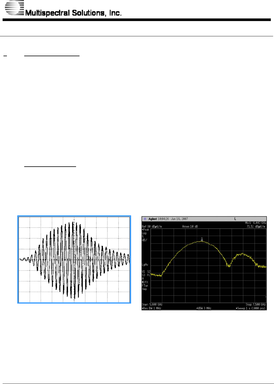
1.1 WBT Description
WBT refers to a technology based on short pulses of Radio Frequency (RF) energy. To
achieve such broad bandwidth waveforms, WBT signals utilize pulses that typically
contain nanosecond bursts of RF energy.
0 1 2 3 4 5
Nanoseconds
Figure 1: Measured Time and Frequency Responses from MSSI C-Band
Transmitter
By virtue of their ultra short peak output and low duty cycle, WBT pulses typically
exhibit extremely low average power. For example, MSSI’s FCC approved 30 milliwatt
RaDeKL Radar ICD
107-201-001 ISSUE 2.10
MULTISPECTRAL SOLUTIONS, INC. PROPRIETARY AND CONFIDENTIAL
8 of 26
peak power tag has an average transmit power level of only 0.2 nanowatts making it
equivalent to about one ten millionth (1/10,000,000) of a typical cell phone. Of
particular importance is the fact that MSSI’s WBT signal generation can be achieved
through the use of readily available low-cost components.
These short, multiple nanosecond pulses generate a correspondingly wide frequency
domain response, in many ways similar to the spreading observed with conventional
direct sequence spread spectrum (DSSS). With WBT, however, the spread bandwidth is
generated directly and not by modulation with a spreading sequence such as pseudo-noise
(PN) code. Thus, WBT is essentially a time-domain concept in which an extremely short
pulse generates an extremely wide bandwidth signal expressed by the direct Fourier
transform relationship between time and frequency. The resulting very low energy
densities result in a waveform which is exceedingly difficult to intercept and, as a
consequence, very unlikely to cause interference to other wireless systems.
There are two primary reasons for non-interference. First, MSSI’s transmitter operates at
a higher frequency range than 802.11. Second, as stated previously, the energy
transmitted on a per unit Hz basis is so low that it is undetectable by other receivers.
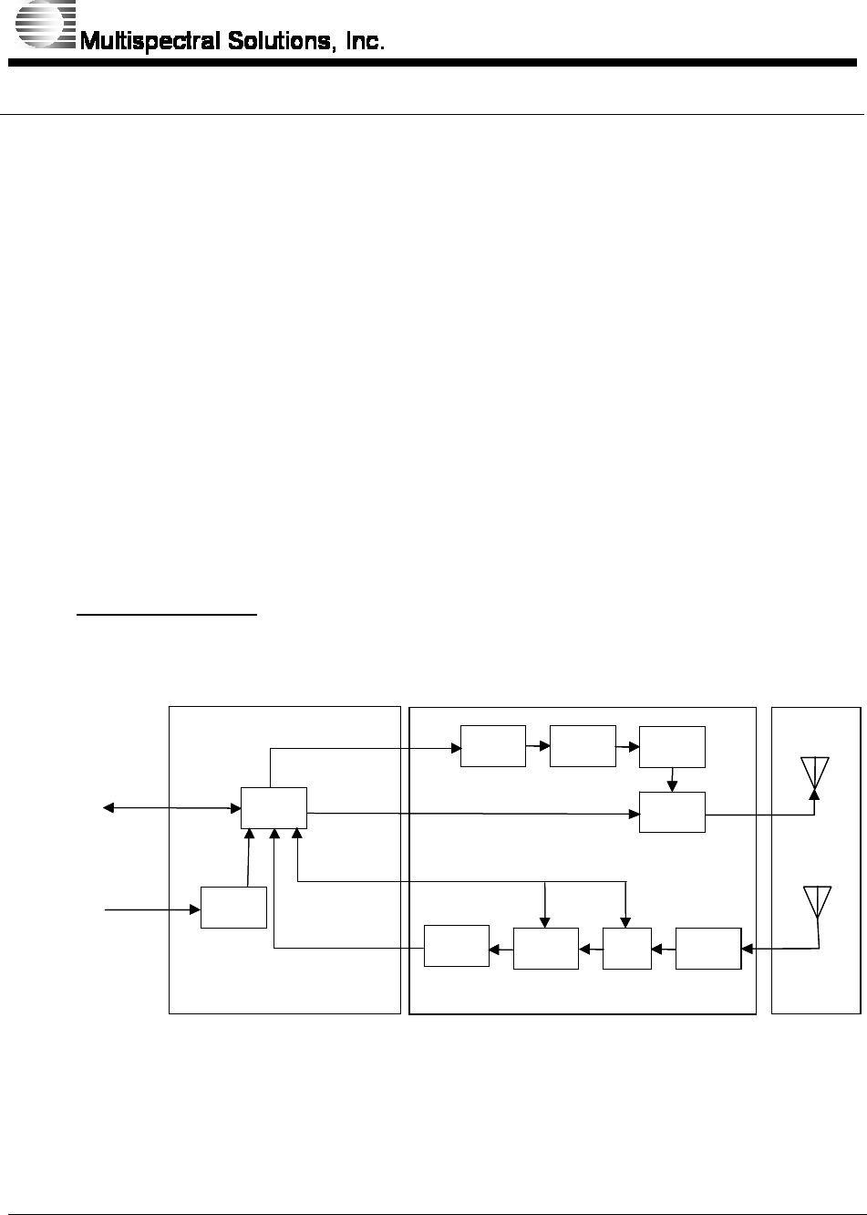
1.2 System Description
A block diagram of the radar is shown below in Figure 2.
Figure 2: WBT Radar System Block Diagram
The radar system is composed of three major components. The first is the return signal
processing and user data interface card. This card controls the radar WBT pulse
Processing Circuit Card
Impuls
Sourc Puls
Shapin Bandpass
Filte
Bandpass
Filte
LN
Diod
Detector
Vide
Conditioning
FPG
Detector
Bia ST
Antenna
C-Band UWB Transmitter
USB -
C-Band UWB Receiver
RF Circuit Card
Powe
Conditioning
7 - 33 V
Communications
Powe
A
djustable
A
ttenuato
r
Detector
Bia ST
C-Band UWB Transmitter
USB -
7 - 33 V
Powe

RaDeKL Radar ICD
107-201-001 ISSUE 2.10
MULTISPECTRAL SOLUTIONS, INC. PROPRIETARY AND CONFIDENTIAL
9 of 26
transmissions and the high speed return signal processing. The second component is the
WBT radio front end circuit card with transmitter which provides short pulse
transmissions spanning the frequency range from 6.0 to 6.5 GHz and the receiver radio
frequency front end which conditions the signal for return processing. The last
component is the dual antenna array providing an antenna each for the transmitter and
receiver to minimize the insertion losses of a switch or circulator. Radar performance
characteristics are summarized in Table 1 below.
Table 1: WBT Radar Performance Characteristics (30 mWatt Version)
RF Characteristics Center Frequency 6.35 GHz
Bandwidth 400 MHz (-3dB)
Peak Power 50 mW EIRP
Antenna Gain 12 dBi w/4x4 array
Antenna FOV 40 deg AZ x 40 deg EL
System Performance Primary Power 1.0 Watt (7.2-35 V
supply)
Range Extent 256 range bins
w/variable offset
Range Resolution 1.0 foot
Data Interface USB 2.0/1.1
Physical
Characteristics Circuit Card Stack Size 2.25 x 3.5 x 0.6 in
w/shield
Individual Antenna Size 2.5 x 2.5 x 0.375 in
Circuit Card Stack Weight 80 grams
Individual Antenna Weight 25 grams
MSSI’s patented radar operates by transmitting and receiving a single WBT pulse. Upon
transmission, the digital processor initiates a timer/counter. The receiver RF front end
filters and amplifies the return, passing the signal to the high speed diode amplitude
detector. After a measured time has elapsed corresponding to the minimum range to
initiate detection, the diode detector video output is compared to multiple voltage
threshold levels to determine relative signal strength return. The video stream is sampled
with one nanosecond time steps corresponding to six-inch radar range bins. This receiver
processing technique permits a fast and simple analog-to-digital conversion of the return
signal amplitude over the entire range space in one transmitted pulse. Since the receiver
measures return signal power amplitude, the receiver does not depend on relative motion
of the target but rather only its presence. As a consequence, the detector is capable of
detecting very slow moving targets. The above process is repeated and signal magnitude
RaDeKL Radar ICD
107-201-001 ISSUE 2.10
MULTISPECTRAL SOLUTIONS, INC. PROPRIETARY AND CONFIDENTIAL
10 of 26
levels are chosen based upon their exceeding threshold 13 out of 16 times. By re-
sampling the radar field of view using different threshold settings, it is possible to
improve return signal amplitude resolution to improve the understanding of the reflective
radar environment.
Since the radar was developed to support radar signal processing, the antenna beam
pattern is shown in the following figures for different frequencies and elevation and
azimuth planar cuts. These figures represent the general antenna pattern characteristics.
The true pattern will vary slightly from the one shown in the figure. The actual antenna
pattern must be determined with a calibration range.
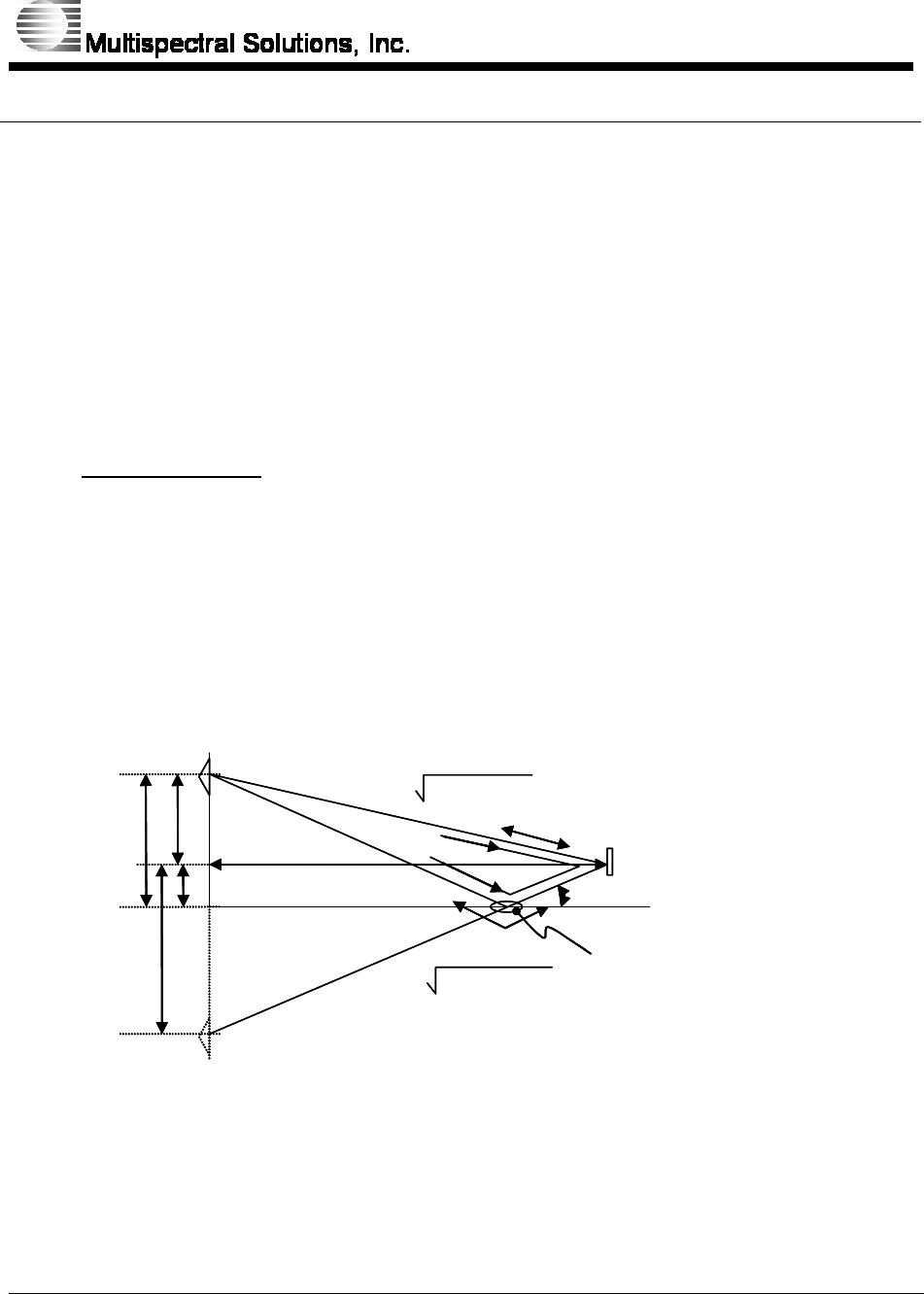
1.3 System Operation
One important phenomenon that is necessary to understand for the operation of the radar
is the effect of multi-path on surface-to-surface radar detection performance. When the
radar is mounted near the ground with targets near the ground, the reflection from the
earth in the transmit and receive paths provides some cancellation of the direct path
signal due to the fact that these ground bounce paths are slightly longer with a phase
reversal upon reflection. Figure 3 illustrates the potential signal paths between the radar
sensor head and the target.
Figure 3: Surface-to-Surface Radar Operation with Multipath
Since the reflections combine with the direct path signal, the radar return will observe
both constructive and destructive interference depending on the heights sensor head and
target and the range between the sensor head and target. Figure 4 shows the variation of
ha
htR
ha-ht
ha+ht
Ldirect = (ha-ht)2+ R2
Lreflect = (ha+ht)2+ R2
θ (Incidence Angle)
1
3
2
4Reflectivity of
the surface
ha
htR
ha-ht
ha+ht
Ldirect = (ha-ht)2+ R2
Lreflect = (ha+ht)2+ R2
θ (Incidence Angle)
1
3
2
4Reflectivity of
the surface
RaDeKL Radar ICD
107-201-001 ISSUE 2.10
MULTISPECTRAL SOLUTIONS, INC. PROPRIETARY AND CONFIDENTIAL
11 of 26
performance signal strength due to multipath propagation for radar with a two meter
height with a target centered at one meter.
Figure 4: The Affect of Multipath on Radar Performance for a Radar Mounted at
a Two Meter Height and a Target at One Meter Height
10
010
110
210
3
Range (m)
Multipath Gain 2 m ant. (dB)
-8
-6
-4
-2
0
2
4
10
010
110
210
3
Range (m)
Multipath Gain 2 m ant. (dB)
-8
-6
-4
-2
0
2
4
10
010
110
210
3
Range (m)
Multipath Gain 2 m ant. (dB)
-8
-6
-4
-2
0
2
4

RaDeKL Radar ICD
107-201-001 ISSUE 2.10
MULTISPECTRAL SOLUTIONS, INC. PROPRIETARY AND CONFIDENTIAL
12 of 26
2 HARDWARE CONNECTIONS
Each radar unit has the following external connections:
• ON/OFF Switch
• Power LED indicator
• USB Connector (Note unit does not power over USB)
• Power Jack (2.5mm) – Unit requires external power with voltage between 7.2
and 35 volts.

RaDeKL Radar ICD
107-201-001 ISSUE 2.10
MULTISPECTRAL SOLUTIONS, INC. PROPRIETARY AND CONFIDENTIAL
13 of 26
3 USB INTERFACE
RaDeKL uses the FT2232 dual channel USB chip from FTDI. Please reference the D2XX
Programmer's Guide when writing your own software to control the RaDeKL radar. Please
note that when scanning the USB bus using the FTDI drivers, each radar device will
show up as two devices because of the dual channel nature of this chip. Channel A is
reserved for future use and therefore should not be used to communicate to the radar
device. Channel B is configured as the communication endpoint to the radar.
3.1 Radar Interface Commands
The entire operation of the radar unit is controlled by writing to registers at certain
address locations. The only two commands that the radar can interpret are read and write
commands.
Using FTDI driver calls, a packet of five bytes is sent to the radar per command
instruction. From these instructions, the user is able to configure the radar and ultimately
command it to take a single or continuous measurements of the radar return pulse.
3.1.1 Low Level Command Syntax
Write:
<0x77><address_msb><address_lsb><data><0xFF>
Read:
<0x72><address_msb><address_lsb><quantity><0xFF>
Each command is five bytes long. The first byte is the command type – 0x77 for writes
and 0x72 for reads. These are the only two commands type currently supported.
Additional commands may be added in the future. If a command type is not understood
by the radar, the entire command packet is ignored. The next two bytes is the 16-bit
address. Depending on the type of command, the fourth byte is either the actual data to
be written or the quantity of bytes to read. For reads with quantity greater than one, the
address value is the starting address for the block read. Finally, the last byte is the
termination character.
3.1.2 Low Level Response Syntax
Write:
<0x234><0x234><0x234><range_bin1>…<range_bin256><0xFF>
Normally the radar will not give a response when issued a write command to any of the
radar-setting registers. To verify that the write was successful, you may elect to do a

RaDeKL Radar ICD
107-201-001 ISSUE 2.10
MULTISPECTRAL SOLUTIONS, INC. PROPRIETARY AND CONFIDENTIAL
14 of 26
follow-up read to confirm. However, when commanded to do radar detection via register
(address) 0x1, the radar will return the above response. Here, the first three return bytes
are delimiter character, follow by 256 range bin bytes, and finally the termination
character. For continuous detections, the same return-byte pattern is sent.
Read response:
<address_msb><address_lsb><data>…<data><0xFF>
The response for read commands is the address bytes followed by the number of data
requested and then the termination byte.

RaDeKL Radar ICD
107-201-001 ISSUE 2.10
MULTISPECTRAL SOLUTIONS, INC. PROPRIETARY AND CONFIDENTIAL
15 of 26
4 MEMORY MAP
The registers are located within the address space as described in the table below.
Table 2 Register Memory Map
Address Description
0x00 FIRMWARE VERSION ID
0x01 DETECTION
0x02 INTERVAL DURATION
0x03 RF CONTROL
0x04 TX GAIN
0x05 RX ATTENUATION
0x06 RANGE
0x07 DELAY
0x08 SENSITIVITY THRESHOLD1
0x09 SENSITIVITY THRESHOLD2
0x0A SENSITIVITY THRESHOLD3
0x0B SENSITIVITY THRESHOLD4
0x0C SENSITIVITY THRESHOLD5
0x0D SENSITIVITY THRESHOLD6
0x0E SENSITIVITY THRESHOLD7
0x0F SENSITIVITY THRESHOLD8
0x10 SENSITIVITY THRESHOLD9
0x11 SENSITIVITY THRESHOLD10
0x12 SENSITIVITY THRESHOLD11
0x13 SENSITIVITY THRESHOLD12
0x14 SENSITIVITY THRESHOLD13
0x15 SENSITIVITY THRESHOLD14
0x16 SENSITIVITY THRESHOLD15
0x17 SENSITIVITY THRESHOLD16
0x18 SENSITIVITY THRESHOLD17
0x19 SENSITIVITY THRESHOLD18
0x1A SENSITIVITY THRESHOLD19

RaDeKL Radar ICD
107-201-001 ISSUE 2.10
MULTISPECTRAL SOLUTIONS, INC. PROPRIETARY AND CONFIDENTIAL
16 of 26
0x1B SENSITIVITY THRESHOLD20
0x1C SENSITIVITY THRESHOLD21
0x1D SENSITIVITY THRESHOLD22
0x1E SENSITIVITY THRESHOLD23
0x1F SENSITIVITY THRESHOLD24
0x20 SENSITIVITY THRESHOLD25
0x21 SENSITIVITY THRESHOLD26
0x22 SENSITIVITY THRESHOLD27
0x23 SENSITIVITY THRESHOLD28
0x24 SENSITIVITY THRESHOLD29
0x25 SENSITIVITY THRESHOLD30
0x26 SENSITIVITY THRESHOLD31
0x27 SENSITIVITY THRESHOLD32
FPGA Registers
Notes
1. Writing values into unused register bits has no effect. However, to ensure software
compatibility with future, feature-enhanced versions of this product, unused register
bits must be written with logic 0. Reading back unused bits can produce either a
logic 1 or a logic 0; hence, unused register bits should be masked off by software
when read.
2. All configuration bits that can be written can also be read back.
3. Writable register bits are cleared to logic 0 upon reset unless otherwise noted.
4. Writing into read-only register bit locations does not affect FPGA operation.

RaDeKL Radar ICD
107-201-001 ISSUE 2.10
MULTISPECTRAL SOLUTIONS, INC. PROPRIETARY AND CONFIDENTIAL
17 of 26
Register 0x00: FIRMWARE VERSION ID
Bit Type Function Default
Bit 7 R FPGA_VERS[7] X
Bit 6 R FPGA _VERS[6] X
Bit 5 R FPGA _VERS[5] X
Bit 4 R FPGA _VERS[4] X
Bit 3 R FPGA _VERS[3] X
Bit 2 R FPGA _VERS[2] X
Bit 1 R FPGA _VERS[1] X
Bit 0 R FPGA _VERS[0] X
FPGA_VERS[7:0]
This register indicates the version ID of the FPGA load. It is incremented
from 0 to indicate FPGA revisions.

RaDeKL Radar ICD
107-201-001 ISSUE 2.10
MULTISPECTRAL SOLUTIONS, INC. PROPRIETARY AND CONFIDENTIAL
18 of 26
Register 0x01: DETECTION
Bit Type Function Default
Bit 7 RESERVED 0
Bit 6 RESERVED 0
Bit 5 RESERVED 0
Bit 4 RESERVED 0
Bit 3 RESERVED 0
Bit 2 R/W PERFORM_CONT 0
Bit 1 RESERVED 0
Bit 0 R/W PERFORM_DETECT 0
PERFORM_DETECT
Set this bit high to perform a single detection. This bit resets itself when
operation is complete. The return is three preamble bytes (0x234) follow by
256 bytes of amplitude return data (one binary byte per range bin) and a
termination byte.
PERFORM_CONT
Set this bit high to perform continuous detections. Manually reset this bit to
stop continuous detections.

RaDeKL Radar ICD
107-201-001 ISSUE 2.10
MULTISPECTRAL SOLUTIONS, INC. PROPRIETARY AND CONFIDENTIAL
19 of 26
Register 0x02: INTERVAL_DURATION
Bit Type Function Default
Bit 7 RESERVED 0
Bit 6 RESERVED 0
Bit 5 RESERVED 0
Bit 4 RESERVED 0
Bit 3 RESERVED 0
Bit 2 R/W INTVL_DUR[2] 1
Bit 1 R/W INTVL_DUR[1] 0
Bit 0 R/W INTVL_DUR[0] 0
INTVL_DUR[2:0]
This register sets the time duration interval between successive RADAR
detections. This value is used during Continuous Radar Detections. The
table below specifies the duration values:
INTVL_DUR[2:0] Time Value
000 1 Sec
001 500 ms
010 250 ms
011 100 ms
100 50 ms

RaDeKL Radar ICD
107-201-001 ISSUE 2.10
MULTISPECTRAL SOLUTIONS, INC. PROPRIETARY AND CONFIDENTIAL
20 of 26
Register 0x03: RF_CONTROL
Bit Type Function Default
Bit 7 R/W RX_ENABLE 0
Bit 6 RESERVED 0
Bit 5 RESERVED 0
Bit 4 RESERVED 0
Bit 3 RESERVED 0
Bit 2 RESERVED 0
Bit 1 RESERVED 0
Bit 0 R/W CNTRL_REG_RESET 0
CNTRL_REG_RESET
This bit resets the digital control registers when set high. All registers will
reset to their default values. Any active radar operation will terminate as well.
RX_ENABLE
This bit controls the switched power supply on the RF receiver board – “high”
to turn on, “low” to turn off. During normal operation, the RF receiver gets
switched on automatically during detection and switched off thereafter. This is
to conserve battery life. This bit should be left in the default off value.

RaDeKL Radar ICD
107-201-001 ISSUE 2.10
MULTISPECTRAL SOLUTIONS, INC. PROPRIETARY AND CONFIDENTIAL
21 of 26
Register 0x04: Transmitter Gain
Bit Type Function Default
Bit 7 RESERVED 0
Bit 6 RESERVED 0
Bit 5 R/W TX_GAIN[5] 1
Bit 4 R/W TX_GAIN[4] 1
Bit 3 R/W TX_GAIN[3] 0
Bit 2 R/W TX_GAIN[2] 1
Bit 1 R/W TX_GAIN[1] 0
Bit 0 R/W TX_GAIN[0] 1
TX_GAIN[5:0]
The TX GAIN register controls the power output level of the RF transmitter.
Max power is achieved when this register is set at 0x3F. Each numeric value
below this level corresponds to an 0.5 dB attenuation from the max.
Examples of some typical settings are shown below.
TX_GAIN[5:0] TX Power
0x3F Max (0dB)
0x3D -1dB
0x39 -3dB
0x33 -6dB
0x2B -10dB
RaDeKL Radar ICD
107-201-001 ISSUE 2.10
MULTISPECTRAL SOLUTIONS, INC. PROPRIETARY AND CONFIDENTIAL
22 of 26
Register 0x05: Receiver Attenuation
Bit Type Function Default
Bit 7 R/W RX_ATTN[7] 0
Bit 6 R/W RX_ATTN[6] 0
Bit 5 R/W RX_ATTN[5] 0
Bit 4 R/W RX_ATTN[4] 0
Bit 3 R/W RX_ATTN[3] 0
Bit 2 R/W RX_ATTN[2] 0
Bit 1 R/W RX_ATTN[1] 0
Bit 0 R/W RX_ATTN[0] 0
RX_ATTN[7:0]
The RX ATTENUATION register sets the receiver attenuation level. If the
return signal is so strong that it saturates the receiver front end, set Max
power is achieved when this register is set at 0x3F. Each numeric value
below this level corresponds to an 0.5 dB attenuation from the max.
Examples of some typical settings are shown below.
RX_ATTN[7:0] RX Level
0x00 Min (0dB)
0x5B -10dB
0x9D -20dB

RaDeKL Radar ICD
107-201-001 ISSUE 2.10
MULTISPECTRAL SOLUTIONS, INC. PROPRIETARY AND CONFIDENTIAL
23 of 26
Register 0x06: RANGE
Bit Type Function Default
Bit 7 R/W RANGE[7] 0
Bit 6 R/W RANGE[6] 0
Bit 5 R/W RANGE[5] 0
Bit 4 R/W RANGE[4] 0
Bit 3 R/W RANGE[3] 0
Bit 2 R/W RANGE[2] 0
Bit 1 R/W RANGE[1] 0
Bit 0 R/W RANGE[0] 0
RANGE[7:0]
This register sets the beginning range in 512 feet intervals where the unit will
start to sample the return energy. A value of 0x00 means that the unit will
look at objects from 1 – 256 feet. A value of 0x01 is for the range of 513 –
769 feet, and so forth for higher values. Although valid values for this register
are from 0x00 to 0xFF, the maximum range is highly dependant on transmitter
power, antenna gain, and receiver sensitivity.

RaDeKL Radar ICD
107-201-001 ISSUE 2.10
MULTISPECTRAL SOLUTIONS, INC. PROPRIETARY AND CONFIDENTIAL
24 of 26
Register 0x07: DELAY
Bit Type Function Default
Bit 7 R/W DELAY[7] 0
Bit 6 R/W DELAY[6] 0
Bit 5 R/W DELAY[5] 0
Bit 4 R/W DELAY[4] 0
Bit 3 R/W DELAY[3] 0
Bit 2 R/W DELAY[2] 0
Bit 1 R/W DELAY[1] 0
Bit 0 R/W DELAY[0] 0
DELAY[7:0]
This register sets the delay value in 8 feet intervals when the unit will start
sampling the return energy. This register, along with register 0x06 (RANGE),
allows for specified distances to be monitored. A value of 0x00 means that the
unit will not delay and start sampling immediately. Each delay value will shift the
256 range bins by (DELAY[7:0] * 8) feet.
RaDeKL Radar ICD
107-201-001 ISSUE 2.10
MULTISPECTRAL SOLUTIONS, INC. PROPRIETARY AND CONFIDENTIAL
25 of 26
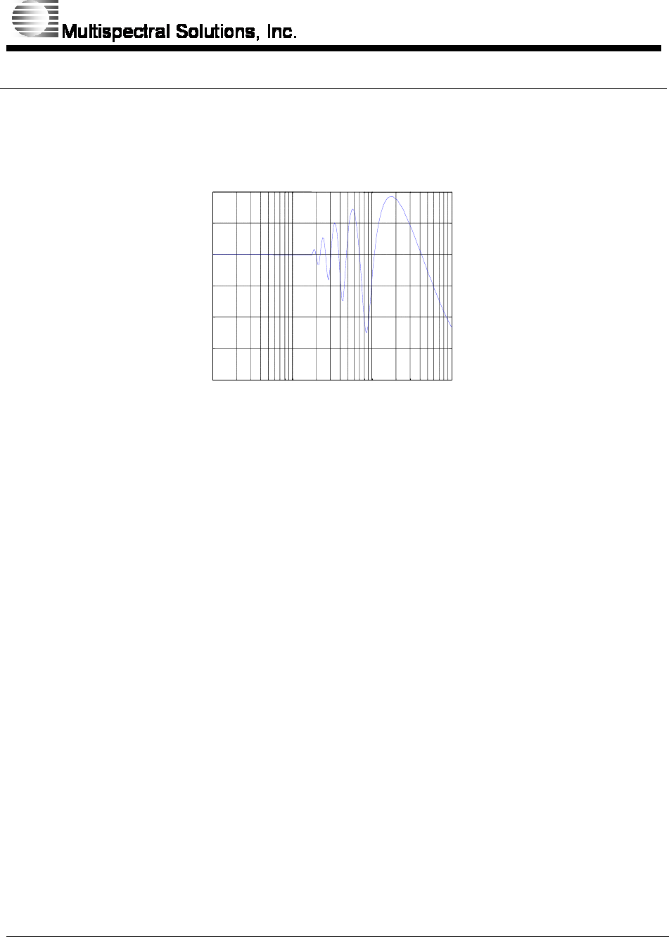
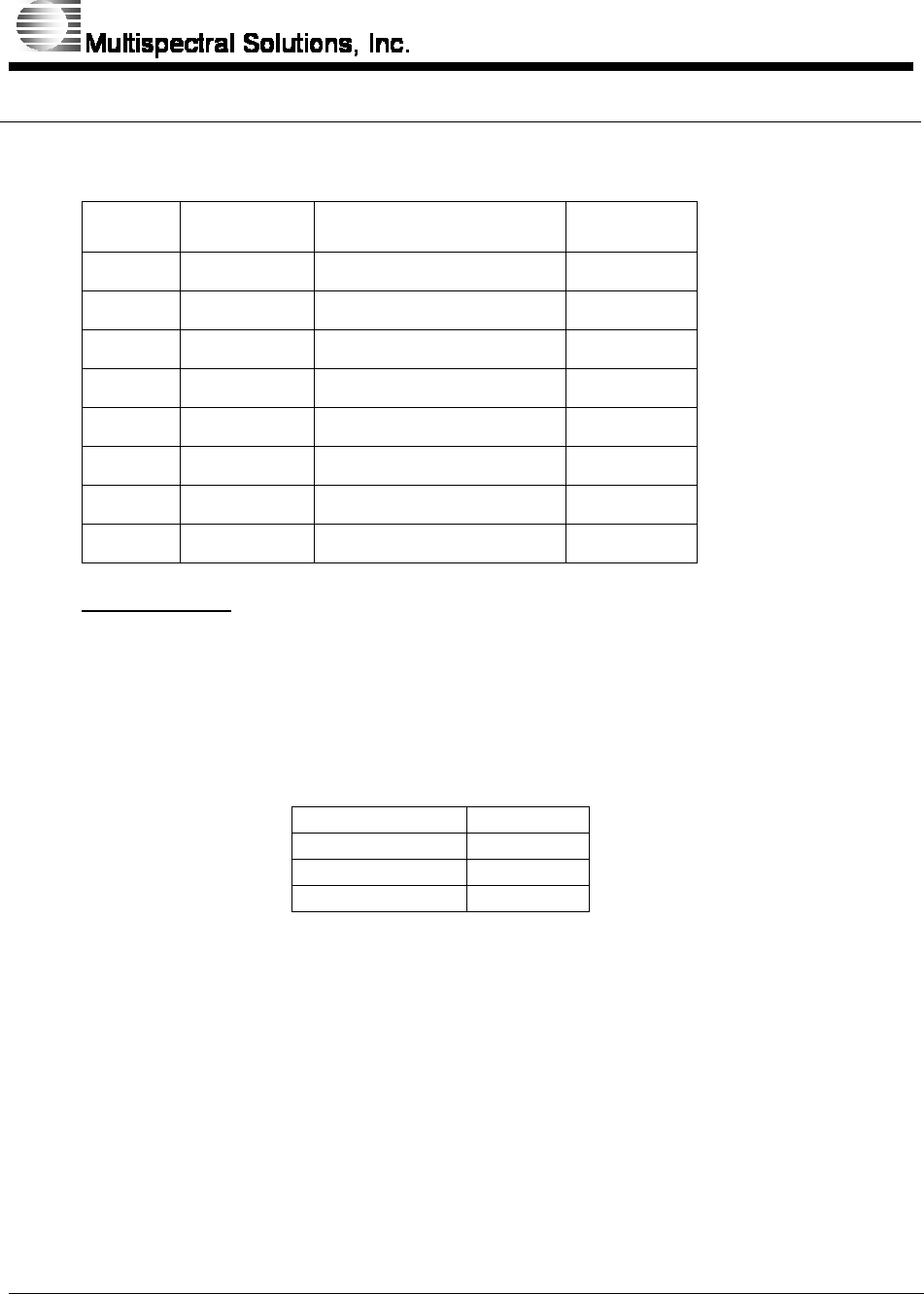
Register 0x08 – 0x27: SENSITIVITY_THRESHOLDx
Bit Type Function Default
Bit 7 R/W SEN_THRESHx[7] 1
Bit 6 R/W SEN_THRESHx[6] 0
Bit 5 R/W SEN_THRESHx[5] 1
Bit 4 R/W SEN_THRESHx[4] 0
Bit 3 R/W SEN_THRESHx[3] 0
Bit 2 R/W SEN_THRESHx[2] 0
Bit 1 R/W SEN_THRESHx[1] 0
Bit 0 R/W SEN_THRESHx[0] 0
SEN_THRESHx[7:0]
These registers set the threshold level to compare against the return energy
signal from the receiver. Setting the threshold level too sensitive (exceeding
or within the noise floor of the receiver) may cause many false triggers
resulting in false alarms. Note each sensitivity threshold settings (register
08h – 27h) are independent of each other. They may be set arbitrarily relative
to each other, but in general, are set in an ascending or descending numeric
order.
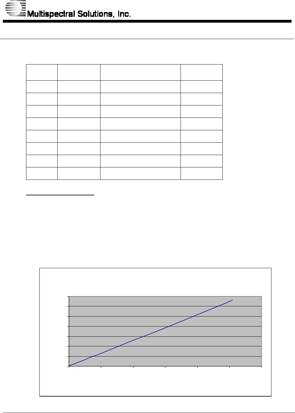
Sensitivity Threshold
0
0.5
1
1.5
2
2.5
3
3.5
0 50 100 150 200 250 300
DAC Setting
Threshold Voltage

RaDeKL Radar ICD
107-201-001 ISSUE 2.10
MULTISPECTRAL SOLUTIONS, INC. PROPRIETARY AND CONFIDENTIAL
26 of 26
The noise floor of the receiver is around 3.0V ± 50mV, thus the usable
sensitivity threshold range is from 0V – 3.0V (corresponding to a setting from
0x00 to 0xEA).