Zebra Technologies RADEKL Radar Development Kit User Manual Hardware Level ICD
Zebra Technologies Corporation Radar Development Kit Hardware Level ICD
UserManual.wiki
>
Zebra Technologies
>
RADEKL User Manual
>
Hardware Level ICD
Contents
1.
Programmers Guide
2.
Hardware Level ICD
3.
Radar Help User Manual
Hardware Level ICD
Navigation menu
Upload a User Manual
Namespaces
Wiki Guide
HTML
PDF
Info
Views
User Manual
Discussion / Help
Navigation
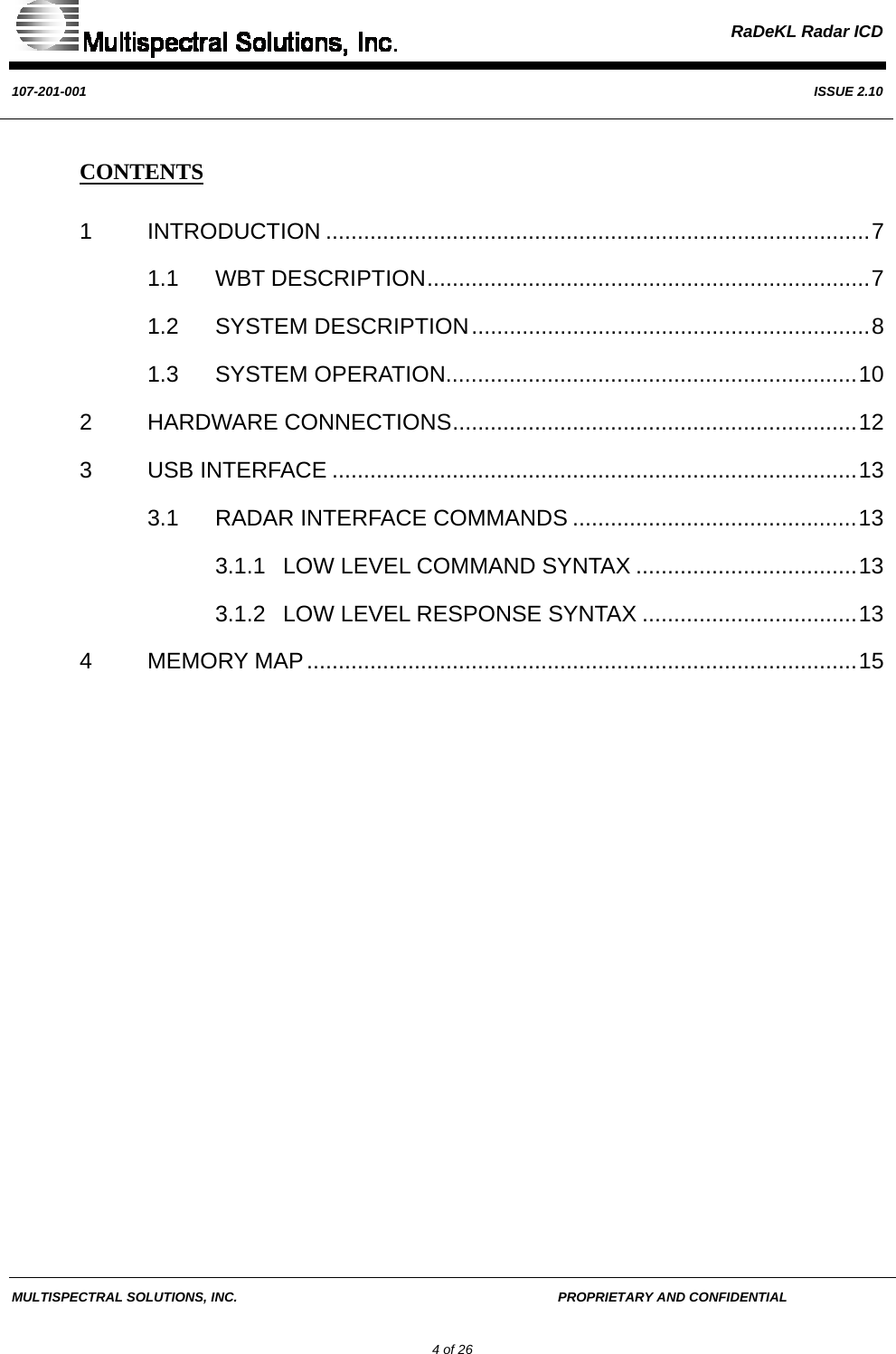
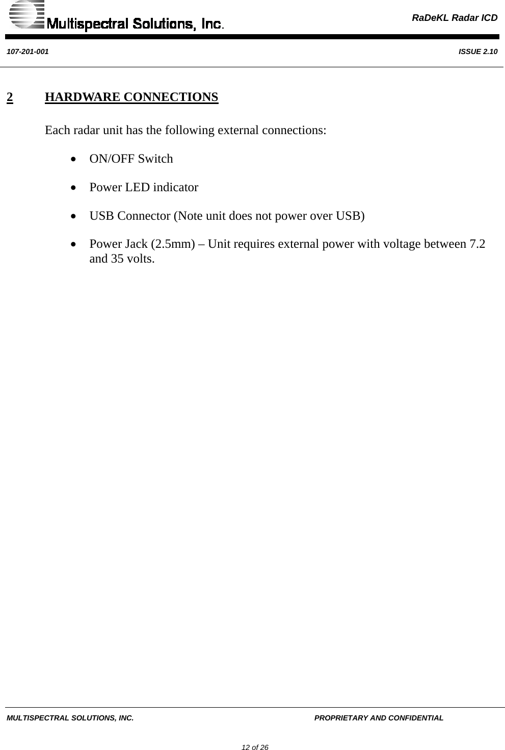
![RaDeKL Radar ICD 107-201-001 ISSUE 2.10 MULTISPECTRAL SOLUTIONS, INC. PROPRIETARY AND CONFIDENTIAL 17 of 26 Register 0x00: FIRMWARE VERSION ID Bit Type Function Default Bit 7 R FPGA_VERS[7] X Bit 6 R FPGA _VERS[6] X Bit 5 R FPGA _VERS[5] X Bit 4 R FPGA _VERS[4] X Bit 3 R FPGA _VERS[3] X Bit 2 R FPGA _VERS[2] X Bit 1 R FPGA _VERS[1] X Bit 0 R FPGA _VERS[0] X FPGA_VERS[7:0] This register indicates the version ID of the FPGA load. It is incremented from 0 to indicate FPGA revisions.](https://usermanual.wiki/Zebra-Technologies/RADEKL.Hardware-Level-ICD/User-Guide-853779-Page-17.png)
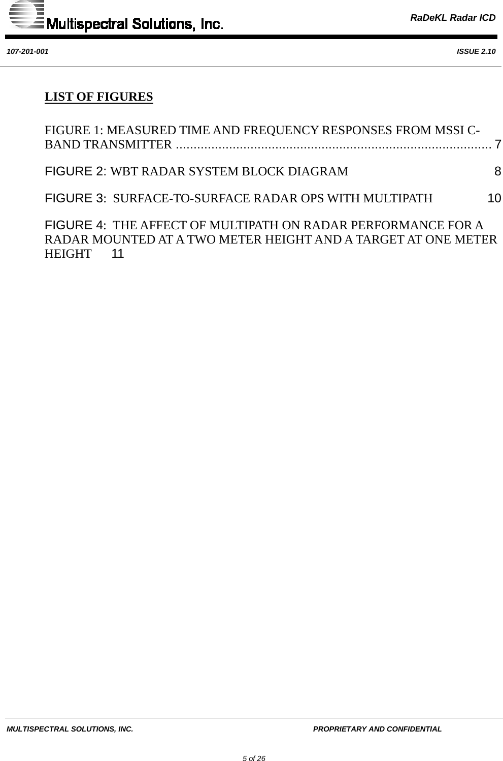
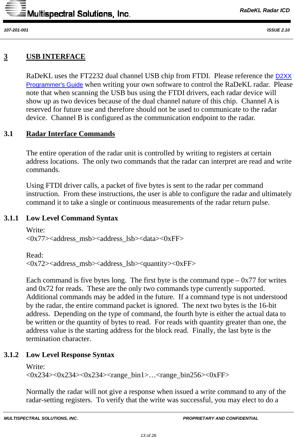
![RaDeKL Radar ICD 107-201-001 ISSUE 2.10 MULTISPECTRAL SOLUTIONS, INC. PROPRIETARY AND CONFIDENTIAL 19 of 26 Register 0x02: INTERVAL_DURATION Bit Type Function Default Bit 7 RESERVED 0 Bit 6 RESERVED 0 Bit 5 RESERVED 0 Bit 4 RESERVED 0 Bit 3 RESERVED 0 Bit 2 R/W INTVL_DUR[2] 1 Bit 1 R/W INTVL_DUR[1] 0 Bit 0 R/W INTVL_DUR[0] 0 INTVL_DUR[2:0] This register sets the time duration interval between successive RADAR detections. This value is used during Continuous Radar Detections. The table below specifies the duration values: INTVL_DUR[2:0] Time Value 000 1 Sec 001 500 ms 010 250 ms 011 100 ms 100 50 ms](https://usermanual.wiki/Zebra-Technologies/RADEKL.Hardware-Level-ICD/User-Guide-853779-Page-19.png)
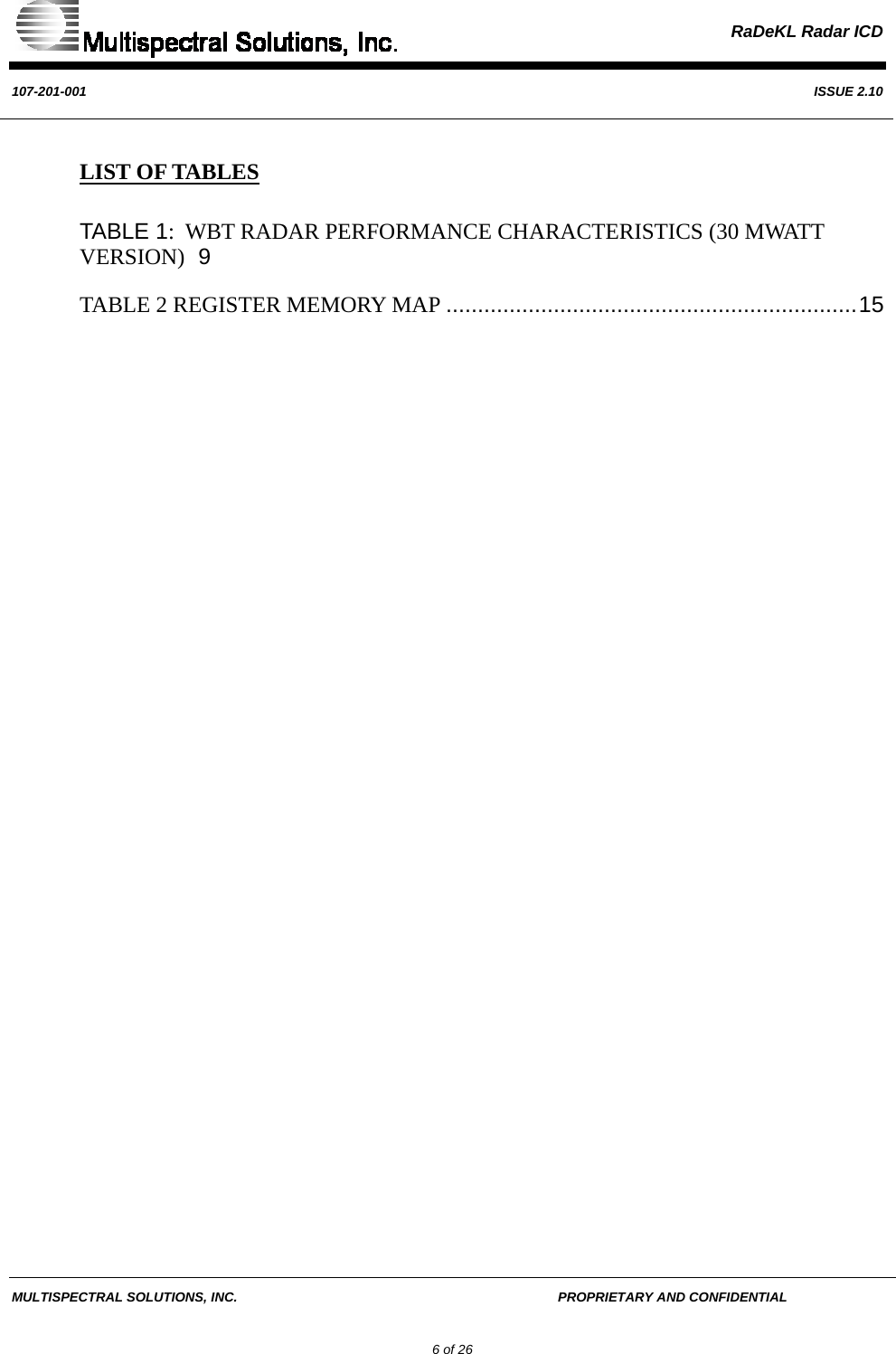
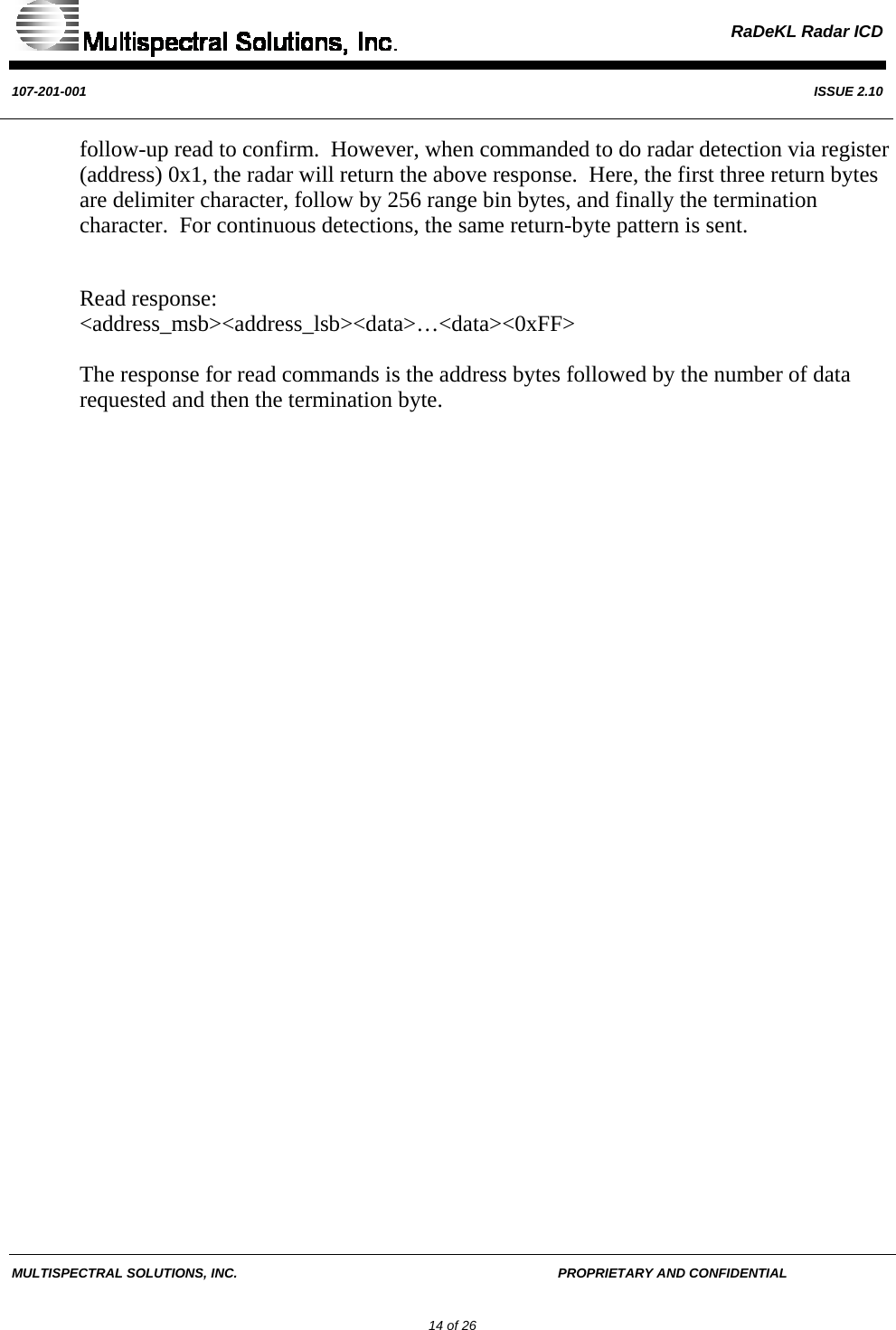
![RaDeKL Radar ICD 107-201-001 ISSUE 2.10 MULTISPECTRAL SOLUTIONS, INC. PROPRIETARY AND CONFIDENTIAL 21 of 26 Register 0x04: Transmitter Gain Bit Type Function Default Bit 7 RESERVED 0 Bit 6 RESERVED 0 Bit 5 R/W TX_GAIN[5] 1 Bit 4 R/W TX_GAIN[4] 1 Bit 3 R/W TX_GAIN[3] 0 Bit 2 R/W TX_GAIN[2] 1 Bit 1 R/W TX_GAIN[1] 0 Bit 0 R/W TX_GAIN[0] 1 TX_GAIN[5:0] The TX GAIN register controls the power output level of the RF transmitter. Max power is achieved when this register is set at 0x3F. Each numeric value below this level corresponds to an 0.5 dB attenuation from the max. Examples of some typical settings are shown below. TX_GAIN[5:0] TX Power 0x3F Max (0dB) 0x3D -1dB 0x39 -3dB 0x33 -6dB 0x2B -10dB](https://usermanual.wiki/Zebra-Technologies/RADEKL.Hardware-Level-ICD/User-Guide-853779-Page-21.png)
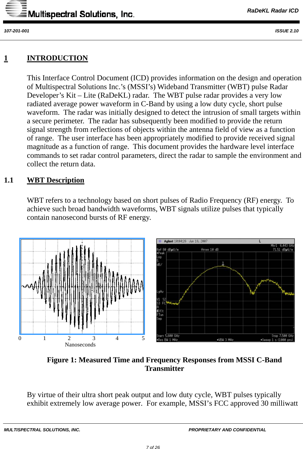
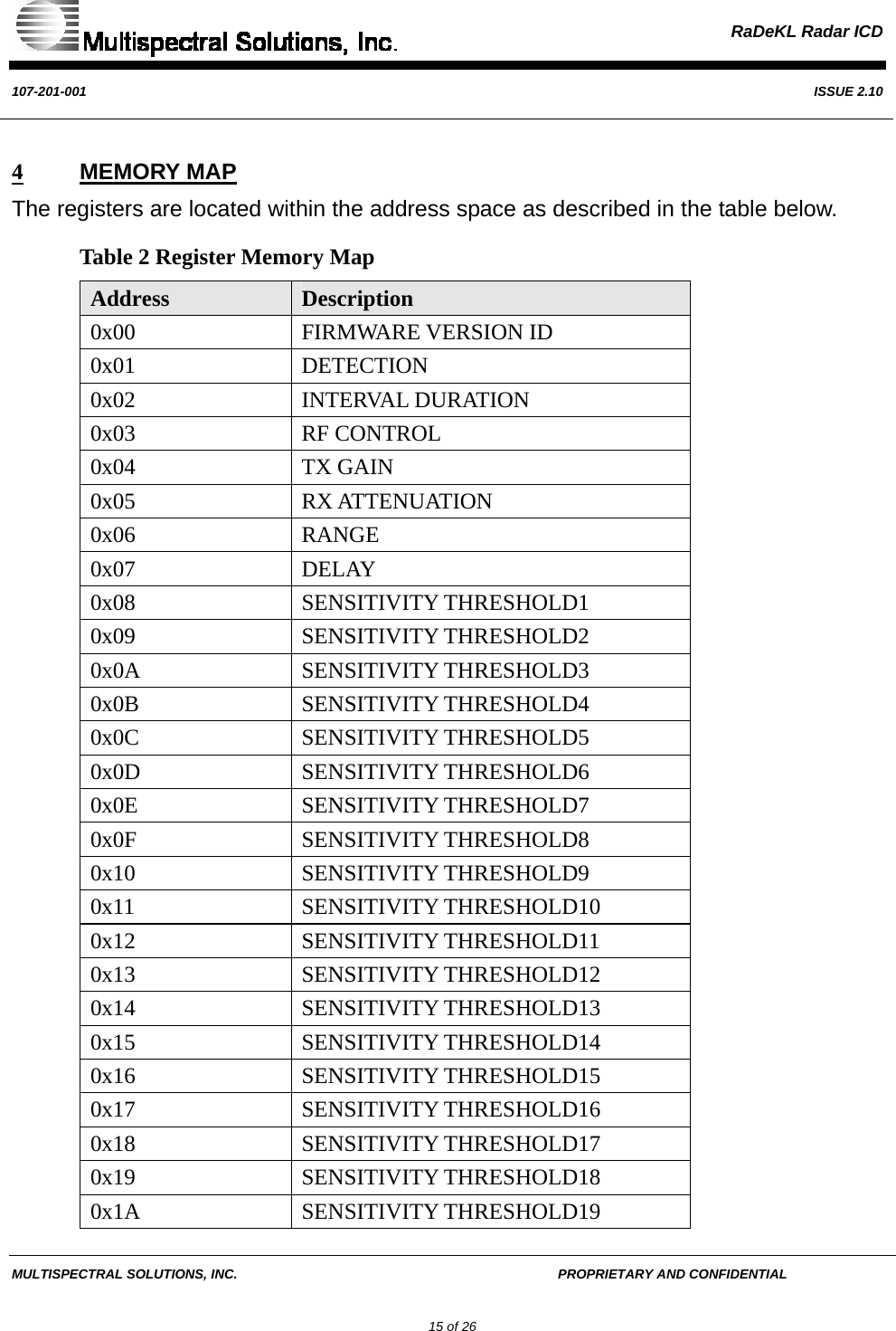
![RaDeKL Radar ICD 107-201-001 ISSUE 2.10 MULTISPECTRAL SOLUTIONS, INC. PROPRIETARY AND CONFIDENTIAL 22 of 26 Register 0x05: Receiver Attenuation Bit Type Function Default Bit 7 R/W RX_ATTN[7] 0 Bit 6 R/W RX_ATTN[6] 0 Bit 5 R/W RX_ATTN[5] 0 Bit 4 R/W RX_ATTN[4] 0 Bit 3 R/W RX_ATTN[3] 0 Bit 2 R/W RX_ATTN[2] 0 Bit 1 R/W RX_ATTN[1] 0 Bit 0 R/W RX_ATTN[0] 0 RX_ATTN[7:0] The RX ATTENUATION register sets the receiver attenuation level. If the return signal is so strong that it saturates the receiver front end, set Max power is achieved when this register is set at 0x3F. Each numeric value below this level corresponds to an 0.5 dB attenuation from the max. Examples of some typical settings are shown below. RX_ATTN[7:0] RX Level 0x00 Min (0dB) 0x5B -10dB 0x9D -20dB](https://usermanual.wiki/Zebra-Technologies/RADEKL.Hardware-Level-ICD/User-Guide-853779-Page-22.png)
![RaDeKL Radar ICD 107-201-001 ISSUE 2.10 MULTISPECTRAL SOLUTIONS, INC. PROPRIETARY AND CONFIDENTIAL 23 of 26 Register 0x06: RANGE Bit Type Function Default Bit 7 R/W RANGE[7] 0 Bit 6 R/W RANGE[6] 0 Bit 5 R/W RANGE[5] 0 Bit 4 R/W RANGE[4] 0 Bit 3 R/W RANGE[3] 0 Bit 2 R/W RANGE[2] 0 Bit 1 R/W RANGE[1] 0 Bit 0 R/W RANGE[0] 0 RANGE[7:0] This register sets the beginning range in 512 feet intervals where the unit will start to sample the return energy. A value of 0x00 means that the unit will look at objects from 1 – 256 feet. A value of 0x01 is for the range of 513 – 769 feet, and so forth for higher values. Although valid values for this register are from 0x00 to 0xFF, the maximum range is highly dependant on transmitter power, antenna gain, and receiver sensitivity.](https://usermanual.wiki/Zebra-Technologies/RADEKL.Hardware-Level-ICD/User-Guide-853779-Page-23.png)
![RaDeKL Radar ICD 107-201-001 ISSUE 2.10 MULTISPECTRAL SOLUTIONS, INC. PROPRIETARY AND CONFIDENTIAL 24 of 26 Register 0x07: DELAY Bit Type Function Default Bit 7 R/W DELAY[7] 0 Bit 6 R/W DELAY[6] 0 Bit 5 R/W DELAY[5] 0 Bit 4 R/W DELAY[4] 0 Bit 3 R/W DELAY[3] 0 Bit 2 R/W DELAY[2] 0 Bit 1 R/W DELAY[1] 0 Bit 0 R/W DELAY[0] 0 DELAY[7:0] This register sets the delay value in 8 feet intervals when the unit will start sampling the return energy. This register, along with register 0x06 (RANGE), allows for specified distances to be monitored. A value of 0x00 means that the unit will not delay and start sampling immediately. Each delay value will shift the 256 range bins by (DELAY[7:0] * 8) feet.](https://usermanual.wiki/Zebra-Technologies/RADEKL.Hardware-Level-ICD/User-Guide-853779-Page-24.png)
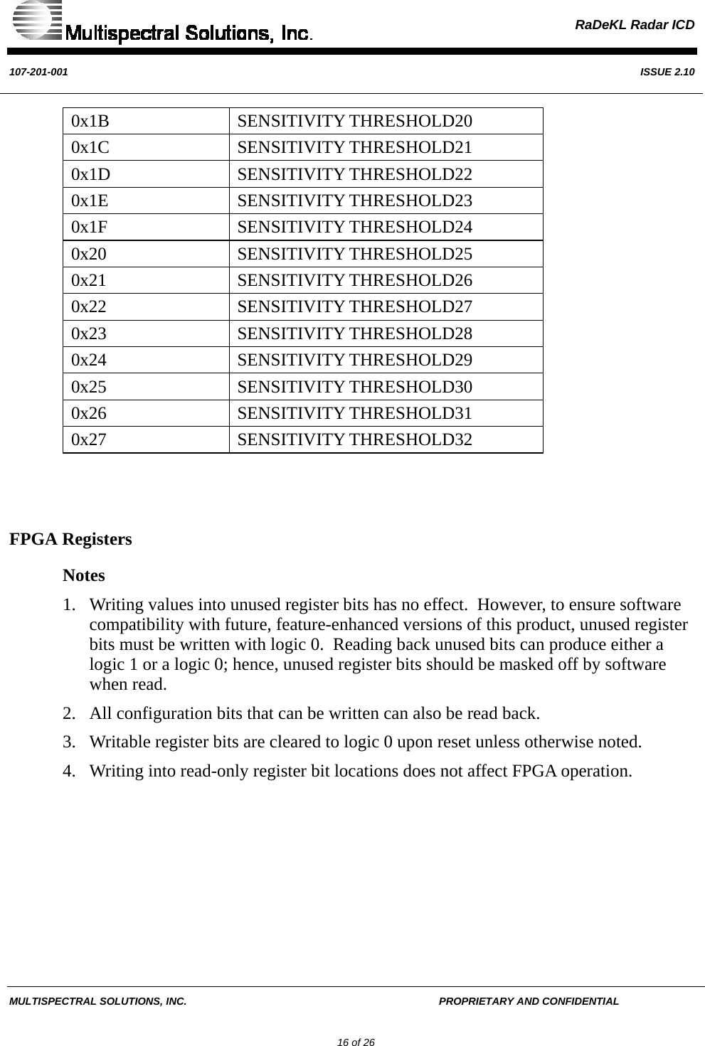
![RaDeKL Radar ICD 107-201-001 ISSUE 2.10 MULTISPECTRAL SOLUTIONS, INC. PROPRIETARY AND CONFIDENTIAL 25 of 26 Register 0x08 – 0x27: SENSITIVITY_THRESHOLDx Bit Type Function Default Bit 7 R/W SEN_THRESHx[7] 1 Bit 6 R/W SEN_THRESHx[6] 0 Bit 5 R/W SEN_THRESHx[5] 1 Bit 4 R/W SEN_THRESHx[4] 0 Bit 3 R/W SEN_THRESHx[3] 0 Bit 2 R/W SEN_THRESHx[2] 0 Bit 1 R/W SEN_THRESHx[1] 0 Bit 0 R/W SEN_THRESHx[0] 0 SEN_THRESHx[7:0] These registers set the threshold level to compare against the return energy signal from the receiver. Setting the threshold level too sensitive (exceeding or within the noise floor of the receiver) may cause many false triggers resulting in false alarms. Note each sensitivity threshold settings (register 08h – 27h) are independent of each other. They may be set arbitrarily relative to each other, but in general, are set in an ascending or descending numeric order. Sensitivity Threshold00.511.522.533.50 50 100 150 200 250 300DAC SettingThreshold Voltage](https://usermanual.wiki/Zebra-Technologies/RADEKL.Hardware-Level-ICD/User-Guide-853779-Page-25.png)