Zebra Technologies RADEKL Radar Development Kit User Manual Radar Help

Zebra Technologies Corporation Radar Development Kit Radar Help

Contents

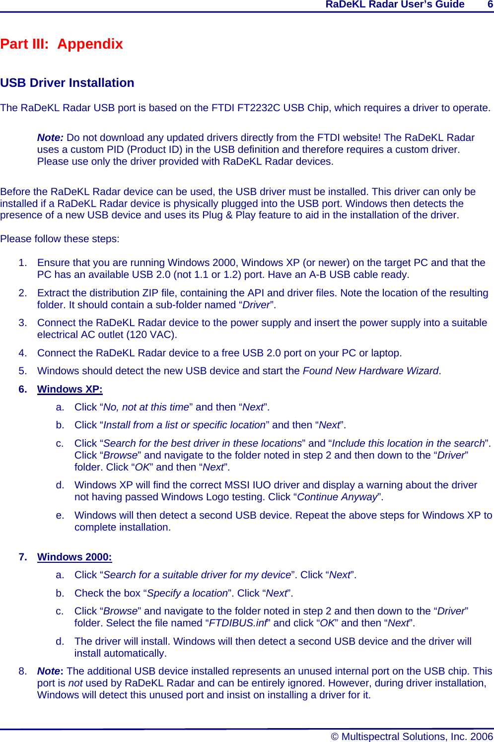
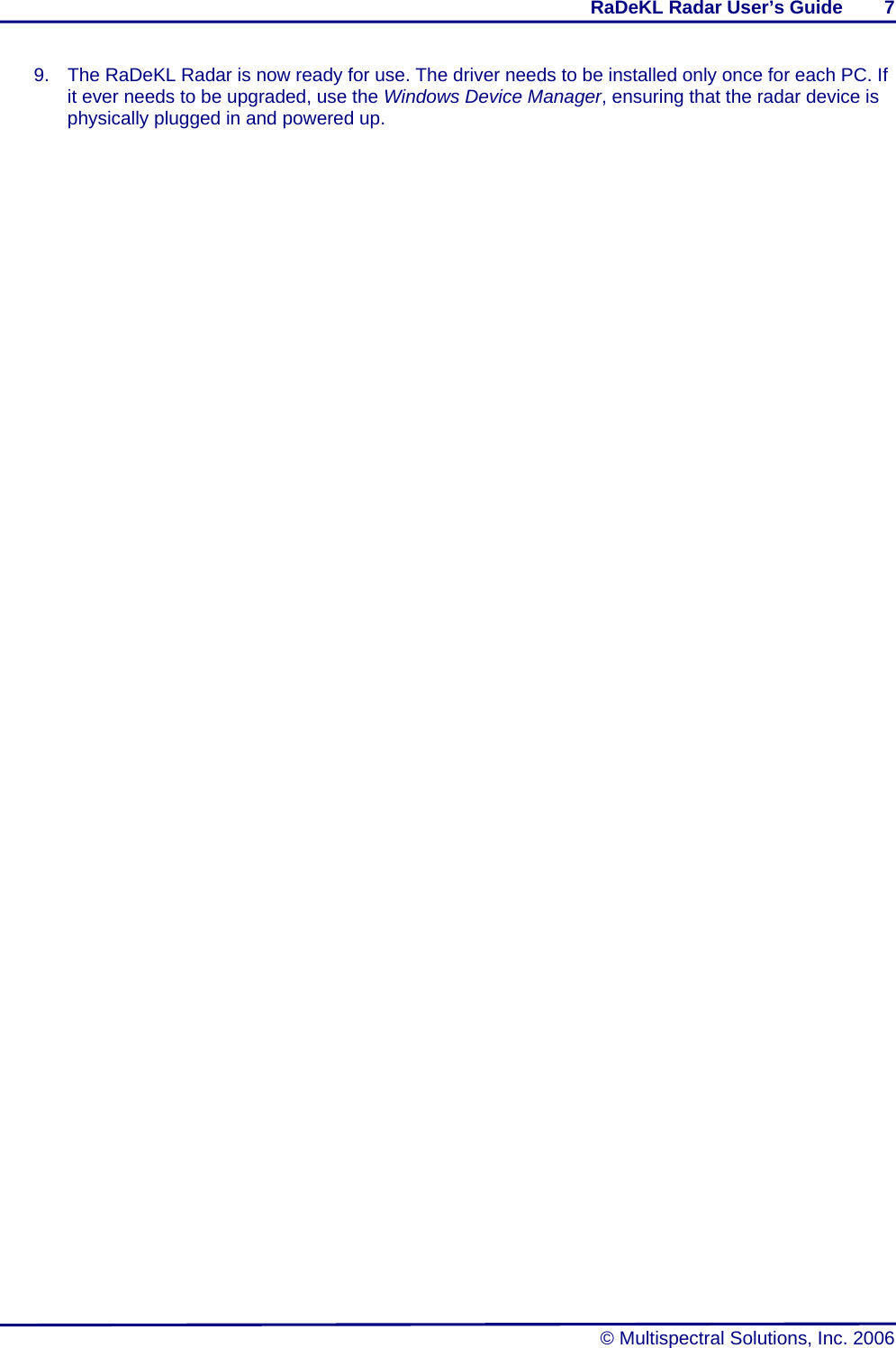
Radar Help User Manual

     ® MULTISPECTRAL SOLUTIONS, INC. ®        Welcome to the RaDeKL Radar GUI Radar Developer’s Kit – Lite    User's Guide And Help File   Please scroll down      Version 2.0 Revised: 05 OCT 07       © 2006 Multispectral Solutions, Inc. 20300 Century Boulevard Germantown, MD 20874-1132 Phone: (301) 528-1745 Fax: (301) 528-1749  Website: www.multispectral.com
   NOTE:  The RaDeKL radar unit has been tested to comply with FCC Part 15, Subpart C for WBT devices.  Changes or modifications to the radiating elements of RaDeKL not expressly approved by the party responsible for compliance could void the user’s authority to operate the equipment.   NOTE: The RaDeKL radar unit has been tested and found to comply with the limits for a Class B digital device, pursuant to part 15 of the FCC Rules. These limits are designed to provide reasonable protection against harmful interference in a residential installation. This equipment generates, uses and can radiate radio frequency energy and, if not installed and used in accordance with the instructions, may cause harmful interference to radio communications. However, there is no guarantee that interference will not occur in a particular installation. If this equipment does cause harmful interference to radio or television reception, which can be determined by turning the equipment off and on, the user is encouraged to try to correct the interference by one or more of the following measures:  —Reorient or relocate the receiving antenna. —Increase the separation between the equipment and receiver. —Connect the equipment into an outlet on a circuit different from that to which the receiver is connected. —Consult the dealer or an experienced radio/TV technician for help.
RaDeKL Radar User’s Guide        I  © Multispectral Solutions, Inc. 2006 Table of Contents  Part I:  Welcome to the RaDeKL Radar GUI ...................................................................1 Introduction.................................................................................................................................... 1 Main Screen Layout....................................................................................................................... 1 Playback Screen Layout ............................................................................................................... 4 Part II:  Usage ...................................................................................................................5 Setup............................................................................................................................................... 5 Display Radar Data........................................................................................................................ 5 File Playback.................................................................................................................................. 5 Part III:  Appendix.............................................................................................................6 USB Driver Installation.................................................................................................................. 6
RaDeKL Radar User’s Guide        1   © Multispectral Solutions, Inc. 2006 Part I:  Welcome to the RaDeKL Radar GUI   Introduction  The RaDeKL Radar GUI provides a simple-to-use interface to the Multispectral Solutions’ RaDeKL Radar device, allowing for the graphical display of radar data as well as the configuration of various operational parameters and settings as well as record/playback of radar data in real-time. This document familiarizes the reader with the features of the RaDeKL Radar application.  Note: Before the RaDeKL Radar unit can be used, the appropriate USB driver must be installed. Refer to the appendix at the bottom for instructions.   Main Screen Layout           1 2 3 45678 9 10 1112
RaDeKL Radar User’s Guide        2   © Multispectral Solutions, Inc. 2006 1. Display Selection Select the type of graphical display: a.  Amplitude: An X-Y graph with range bin numbers (approx. in feet) across the X-axis and radar return value across the Y-axis. b.  Waterfall: Continuous time display with range bin numbers (approx. in feet) across the X-axis and a color-coded radar return values flowing down the top in continuous mode.  2. Filter Settings These filter settings are applied after the data is returned from the radar: a.  Off: no filter is applied. b.  Averaging: Autoregressive smoothing filter (low-pass) over time. Enter a coefficient between 0.000 and 1.000 and click “Apply” to smooth the radar return value over time. This will make abrupt changes appear more smooth c.  MTI: Autoregressive background subtraction filter (high-pass) over time. Enter a coefficient between 0.000 and 1.000 and click “Apply” to highlight changes from the previous sample over time. This filter makes it easier to detect sudden changes in the field of the radar.  3. Clear Display Clicking this button clears the graphical display area.  4. Display Area The graphical display area. This is where the radar data is displayed in graphical form, either as an amplitude or waterfall chart.  5. Status Line The status line shows the status of the radar or the last action requested, along with an icon indicating the run status of the radar or playback file.  6. Range Bins The X-axis of the display area labels the range bin (1-256) displayed horizontally. Each range bin represents a 1-nanosecond interval, which is roughly equivalent to 1 foot. The exact range bin intervals are 11.8 inches (30.0 cm) per range bin.  7.  Zoom Buttons and Scrollbar Zoom horizontally up to 8 times. Once the zoom setting is greater than 1, use the scrollbar to move horizontally over the entire range of range bins. Note: If your PC is slower than 800 MHz or is very busy with other tasks, using a zoom setting of 8 and a Sample Interval of 50 ms (in continuous mode) may result in display lag or even an I/O error, since the application will no longer be able to keep up with the incoming data stream.  8.  Radar / Playback Tabs Switches between active radar and playback modes: a.  Radar: Data is displayed from the actual radar unit attached to the computer.
RaDeKL Radar User’s Guide        3   © Multispectral Solutions, Inc. 2006 b.  Playback: Data is displayed from a previously recorded file containing radar data. See the Playback Screen Layout section below for details.  9. Radar Device Selection a. The pulldown menu allows selection of the desired radar device, if more than one device is connected. It always shows the currently open radar serial number. Selecting a different radar using the pulldown menu automatically opens that radar unit for operation. b. The Description shows the description string, followed by the version of the open radar unit. c.  Reset Radar button: Perform a hard-reset on the radar unit.  10.  Run Radar Buttons a.  Single: Collect a single radar sample (i.e. all 256 range bins for a given snapshot) and display the data in the display area. b.  Continuous: Start collecting continuous samples according to the Sample Interval setting and display the data continuously in the display area. c.  Stop: When in continuous mode, stop the radar.  11. Record Record radar data to a file for later playback. When the recording is started, a dialog box asks for a filename. a.  Single Sample: Record a single sample into a file. b.  nnn Samples: Specify a specific number of samples to record to a file. If the radar is not in continuous mode, continuous mode is temporarily started to record the requested samples. c.  Until Radar Stopped: Record radar samples until continuous mode is stopped. If the radar is not in continuous mode, continuous mode is automatically started.  12. Radar Settings Configure the operational settings of the radar device. These settings are saved in the computer’s registry and are automatically used when the same radar is opened again. a.  DAC Thresholds: Set the linearity of the radar’s sensitivity to the return signal. You may select linear, linear/log (linear at first, then logarithmic), logarithmic or custom. Selecting custom shows a dialog box that allows custom linearity templates (i.e. DAC Thresholds) to be defined and saved with user-defined names. DAC Threshold values must be between 20 and 227. b.  Tx Attenuation: Control the transmit attenuation of the radar by selecting a dB value from the pulldown menu. c.  Rx Attenuation: Control the receive attenuation of the radar by selecting a dB value from the pulldown menu. d.  Range Delay: Set the range offset of the first range bin returned by the radar. For example, selecting 32 feet will cause the display to start at 32 feet along the X-axis. e.  Sample Interval: Sets the sampling interval for continuous mode. For example, 50 msec (the default) will cause a sample to be collected and displayed 20 times per second when the radar is in continuous mode.
RaDeKL Radar User’s Guide        4   © Multispectral Solutions, Inc. 2006 Playback Screen Layout             13. Playback File Allows selection of a pre-recorded playback file and displays that file’s header information.  14. Playback Controls Allows navigation through the playback file: a.   Start / Continue playback at the current location (sample number). b.   Stop playback and rewind back to first sample in file. c.   Pause playback at the current location. d.   Go back one sample. 1513 14
RaDeKL Radar User’s Guide        5   © Multispectral Solutions, Inc. 2006 e.   Skip forward one sample. f.  Go to Sample nnn: Enter a specific sample number to display.  15.  Radar Settings (file) The radar settings as saved in the playback file. These are the same settings that existed when the file was recorded and therefore cannot be changed. Refer to “12. Radar Settings” above for the definitions of individual items.   Part II:  Usage   The RaDeKL Radar application is very straightforward and intuitive to use. Grayed-out buttons indicate that the corresponding function is not allowed within the current context. Follow these steps:  Setup  1.  First, ensure that you have the FTDI USB driver installed (see appendix below). 2.  Ensure that you have the RaDeKL Radar device plugged into the USB port and that the device is powered up. Point the radar unit in the desired direction for measurements.  Display Radar Data  1.  Run the RaDeKL Radar GUI application (there should be a shortcut in the Start / Programs menu). 2.  Ensure that desired radar unit is selected under “Select Radar Device” (if there are multiple units connected). 3.  If you get a warning message saying that there is no RaDeKL Radar device attached, ensure that the radar unit is properly connected and powered up and also that the FTDI USB driver has been correctly installed (see appendix below). 4.  If no radar device is connected to your PC, the application will automatically switch to Simulator mode, giving you access to four simulated, but fully functional radar devices. These allow for testing or demonstration of the GUI without having an actual RaDeKL radar device attached. 5. Under “Run Radar” Click either “Single” or “Continuous” to display the data collected. 6.  Adjust the orientation of the radar unit as needed. 7.  Play with other settings as desired to get the output you need. Note: For most settings to be changed, continuous mode must first be stopped, the setting changed and continuous mode then restarted. 8.  To save radar data to a file for later playback, click the appropriate button under “Record”. A standard Create File dialog box will ask for file name and location of the saved TEXT file.  File Playback  1.  To play back a previously recorded, click the “Playback” tab. 2. Under “Playback File” click “Open” and select the desired data file. 3. Use the “Playback Controls” to play and/or navigate the file.
RaDeKL Radar User’s Guide        6   © Multispectral Solutions, Inc. 2006 Part III:  Appendix   USB Driver Installation  The RaDeKL Radar USB port is based on the FTDI FT2232C USB Chip, which requires a driver to operate.   Note: Do not download any updated drivers directly from the FTDI website! The RaDeKL Radar uses a custom PID (Product ID) in the USB definition and therefore requires a custom driver. Please use only the driver provided with RaDeKL Radar devices.  Before the RaDeKL Radar device can be used, the USB driver must be installed. This driver can only be installed if a RaDeKL Radar device is physically plugged into the USB port. Windows then detects the presence of a new USB device and uses its Plug & Play feature to aid in the installation of the driver.   Please follow these steps:  1.  Ensure that you are running Windows 2000, Windows XP (or newer) on the target PC and that the PC has an available USB 2.0 (not 1.1 or 1.2) port. Have an A-B USB cable ready. 2.  Extract the distribution ZIP file, containing the API and driver files. Note the location of the resulting folder. It should contain a sub-folder named “Driver”. 3.  Connect the RaDeKL Radar device to the power supply and insert the power supply into a suitable electrical AC outlet (120 VAC). 4.  Connect the RaDeKL Radar device to a free USB 2.0 port on your PC or laptop. 5.  Windows should detect the new USB device and start the Found New Hardware Wizard. 6. Windows XP: a. Click “No, not at this time” and then “Next”. b. Click “Install from a list or specific location” and then “Next”. c. Click “Search for the best driver in these locations” and “Include this location in the search”. Click “Browse” and navigate to the folder noted in step 2 and then down to the “Driver” folder. Click “OK” and then “Next”. d.  Windows XP will find the correct MSSI IUO driver and display a warning about the driver not having passed Windows Logo testing. Click “Continue Anyway”. e.  Windows will then detect a second USB device. Repeat the above steps for Windows XP to complete installation.  7. Windows 2000: a. Click “Search for a suitable driver for my device”. Click “Next”. b.  Check the box “Specify a location”. Click “Next”. c. Click “Browse” and navigate to the folder noted in step 2 and then down to the “Driver” folder. Select the file named “FTDIBUS.inf” and click “OK” and then “Next”. d.  The driver will install. Windows will then detect a second USB device and the driver will install automatically. 8.  Note: The additional USB device installed represents an unused internal port on the USB chip. This port is not used by RaDeKL Radar and can be entirely ignored. However, during driver installation, Windows will detect this unused port and insist on installing a driver for it.
RaDeKL Radar User’s Guide        7   © Multispectral Solutions, Inc. 2006 9.  The RaDeKL Radar is now ready for use. The driver needs to be installed only once for each PC. If it ever needs to be upgraded, use the Windows Device Manager, ensuring that the radar device is physically plugged in and powered up.

Navigation menu