Zebra Technologies ZLANGVH Zebra Embedded 802.11b/g radio User Manual ZM400 ZM600 Maintenance Manual
Zebra Technologies Corporation Zebra Embedded 802.11b/g radio ZM400 ZM600 Maintenance Manual
UserManual.wiki
>
Zebra Technologies
>
ZLANGVH User Manual
>
User Manual
Contents
1.
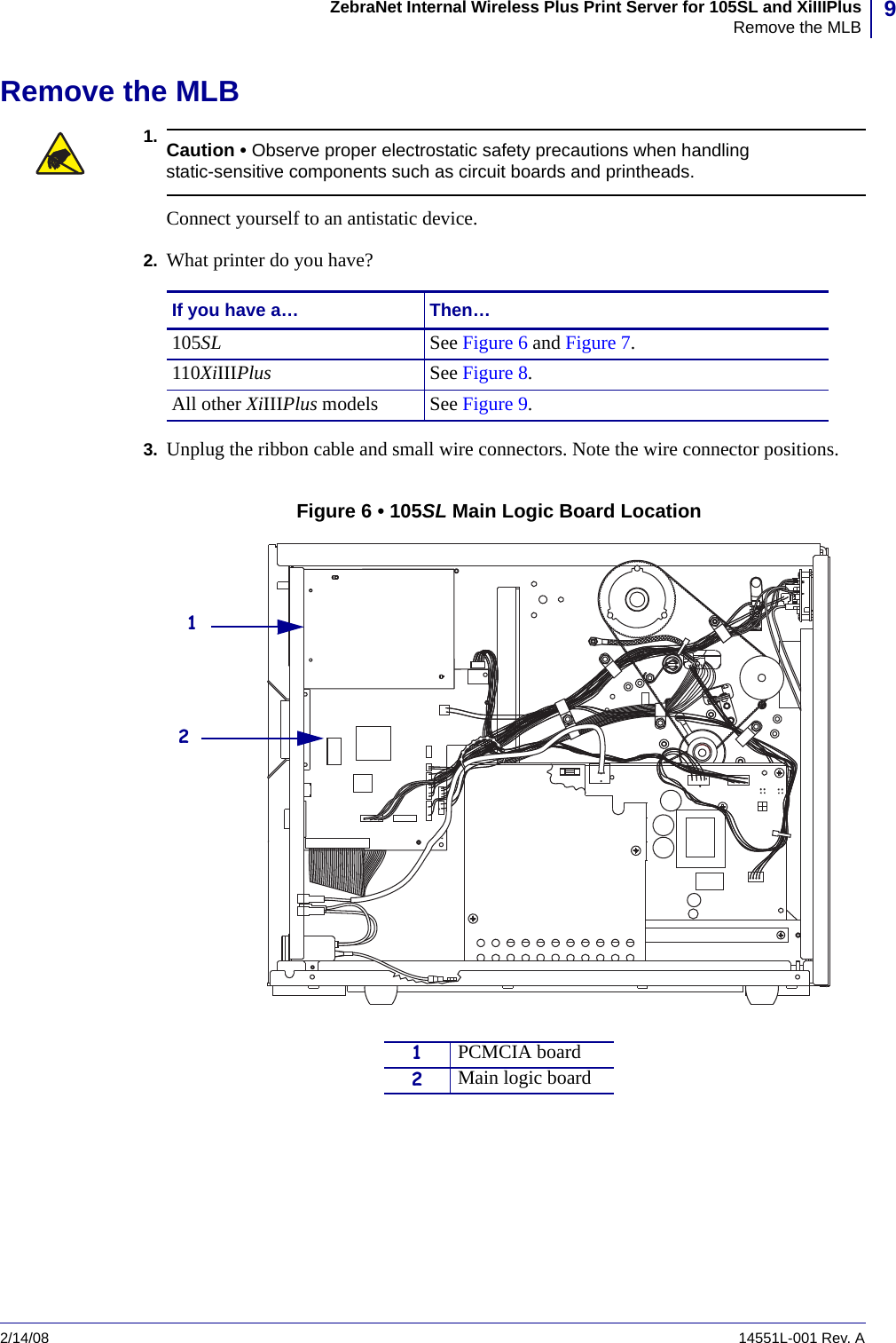
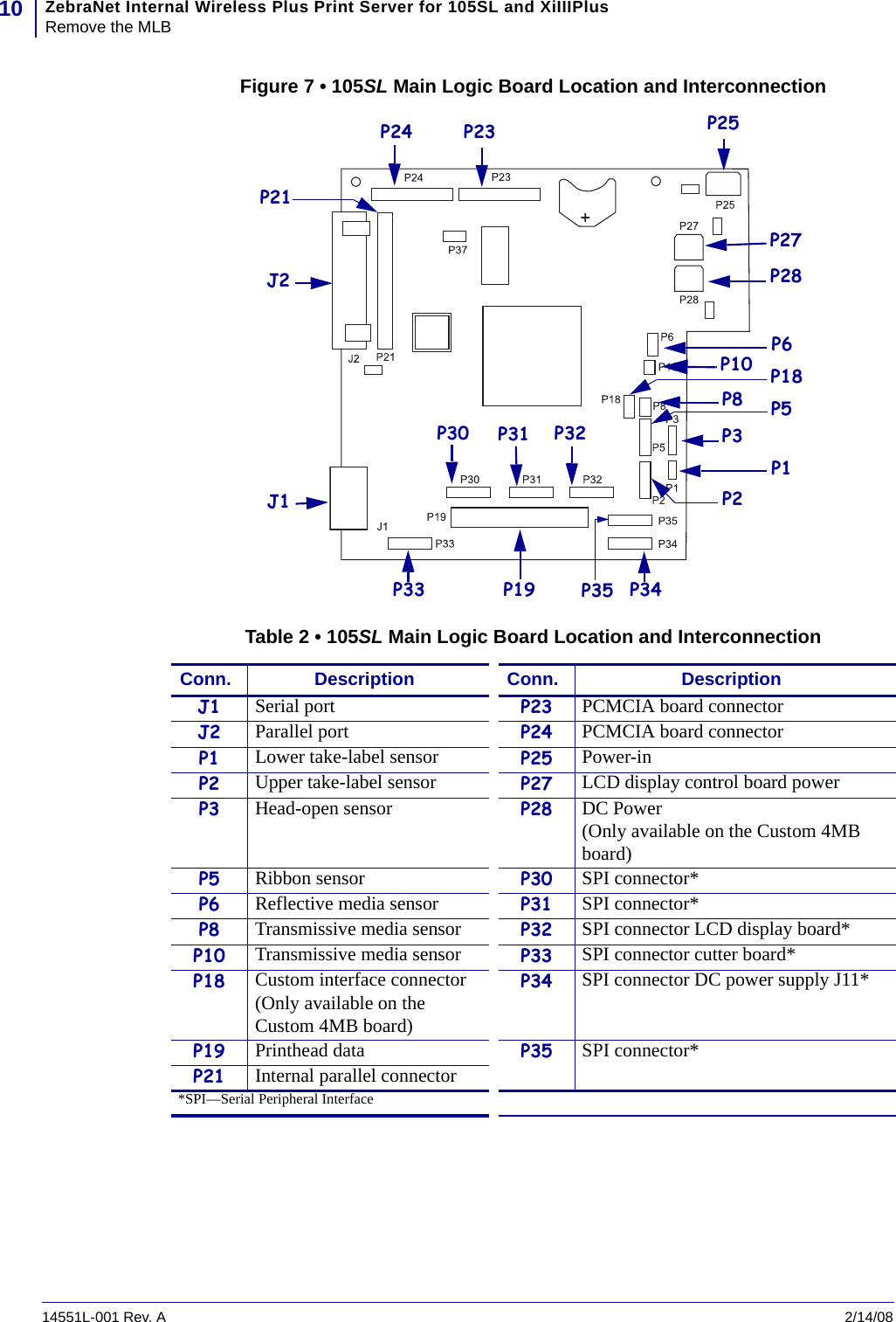
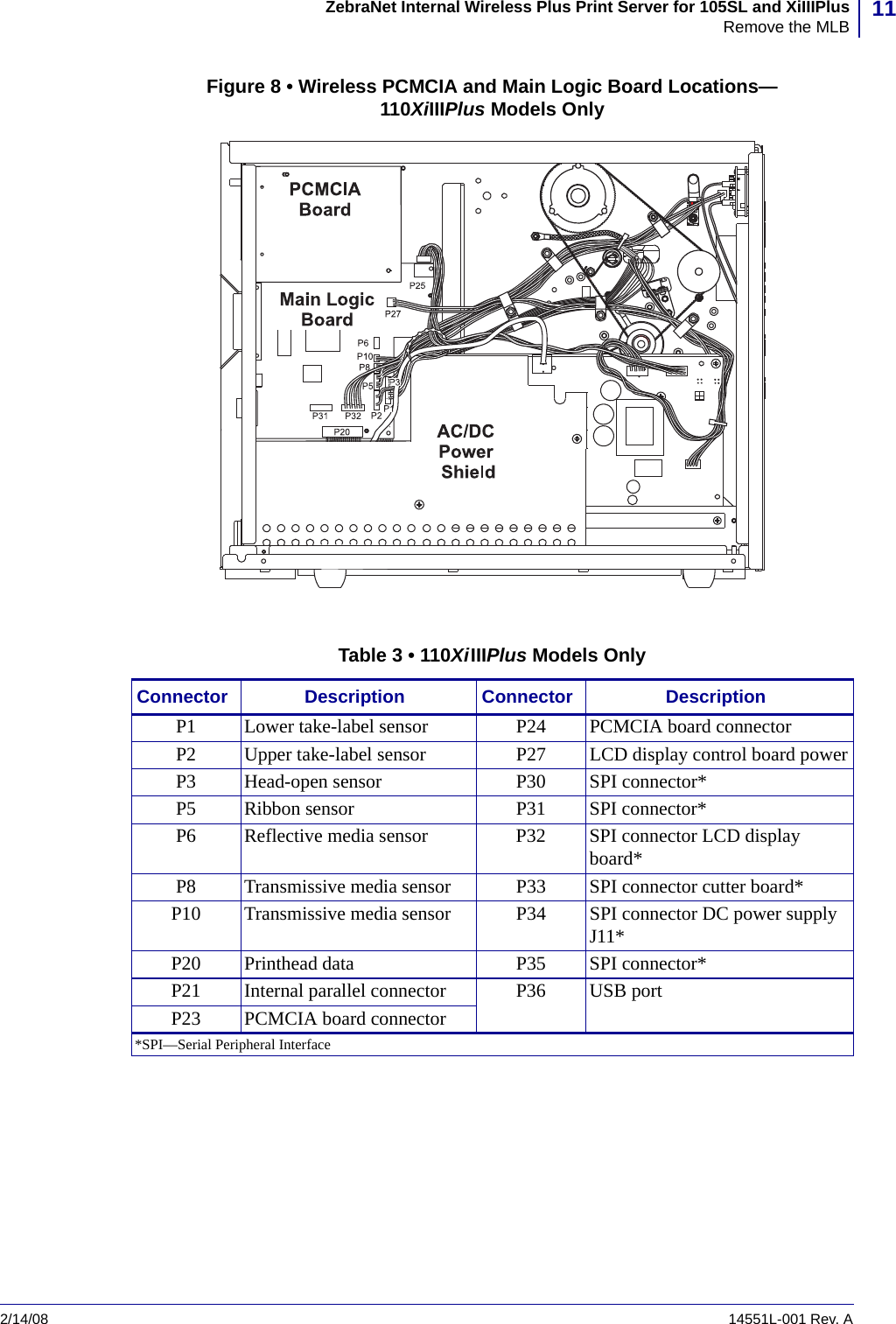
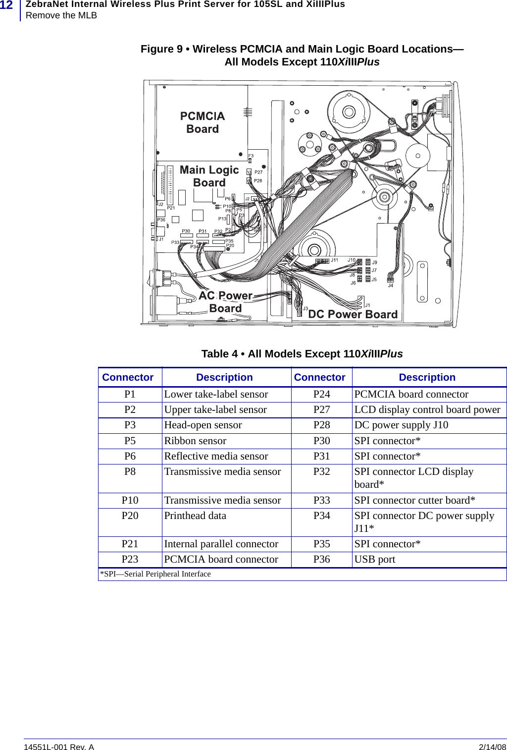
User Manual
2.
User Manual Part 1 of 3
3.
User Manual Part 2 of 3
4.
User Manual Part 3 of 3
User Manual
Navigation menu
Upload a User Manual
Namespaces
Wiki Guide
HTML
PDF
Info
Views
User Manual
Discussion / Help
Navigation