Zebra Technologies ZLANGVH Zebra Embedded 802.11b/g radio User Manual ZM400 ZM600 Maintenance Manual
Zebra Technologies Corporation Zebra Embedded 802.11b/g radio ZM400 ZM600 Maintenance Manual
Contents
User Manual
© 2008 ZIH Corp. All product names and numbers are Zebra
trademarks, and Zebra and the Zebra logo are registered
trademarks of ZIH Corp. All rights reserved.
Printed on
chlorine-free
recycled paper. 14551L-001
ZebraNet® Internal Wireless Plus Print Server
for 105
SL
™and
Xi
III
Plus
™
Installation Instructions
This kit includes the parts and documentation necessary to install the ZebraNet® Internal
Wireless Plus Print Server into the 105SL™ and XiIIIPlus™ printers. Read these instructions
thoroughly prior to kit installation.
Prepare for Installation
Parts List
Before proceeding, verify that your kit contains the items listed below.
Caution • A qualified service technician must perform this installation.
Table 1 • Parts List
3Item Qty Part Number Description
Ref 1MInternal Wireless Plus Print Server Option Maintenance
Kit
1129652-002 Internal Wireless Plus PC Board
2139538 Antenna
3245970-010 Screw, M3 (sold in quantities of 25)
4233291 Spacer
5278114 Nut
61Bracket
Bold = Part available for purchase.
Italic = Part not available for purchase; listed and shown for reference only.
ZebraNet Internal Wireless Plus Print Server for 105SL and XiIIIPlus
Prepare for Installation
2
14551L-001 Rev. A 2/14/08
Figure 1 • Kit Contents
Reference Materials
The following manuals and CDs may be helpful references while performing this procedure.
•ZebraNet
® Wireless User Guide
•105SL User CD
•105SL Maintenance Manual CD
•105SL User Guide
•105SL Maintenance Manual
•XiIIIPlus Series Maintenance Manual
•XiIIIPlus User Guide
•XiIIIPlus Series User Guide (CD)
•110XiIIIPlus Maintenance Manual
•Xi Series Maintenance Manual (CD)
Tools Required
1
2
3
456
Tools • You need these tools to complete this procedure:
Phillips Screwdriver Set
Metric Nutdriver Set
Antistatic Wriststrap and Mat
3
ZebraNet Internal Wireless Plus Print Server for 105SL and XiIIIPlus
Remove the Electronics Cover
2/14/08 14551L-001 Rev. A
Prepare the Printer for Installation
1. Check the bottom right corner of the front panel LCD for the firmware version. You need
firmware version V60.15.X or higher to operate the ZebraNet Internal Wireless Plus Print
Server. If the firmware version number on your printer is lower than this version,
download the latest firmware from http://www.zebra.com.
Remove the Electronics Cover
1.
2.
3. See Figure 2. Remove the two screws that secure the electronics cover.
4. Remove the cover.
Note • Retain all parts removed during disassembly, unless otherwise directed.
Caution • Observe proper electrostatic safety precautions when handling
static-sensitive components such as circuit boards and printheads.
Connect yourself to an antistatic device.
Caution • Turn off (O) the printer and disconnect it from the power source before
performing the following procedure.
Turn off (O) the printer and disconnect the AC power cord and all data cables.
ZebraNet Internal Wireless Plus Print Server for 105SL and XiIIIPlus
Remove the Electronics Cover
4
14551L-001 Rev. A 2/14/08
Figure 2 • Remove or Install the Electronics Cover
1Electronics cover
2Electronics cover mounting screws (2)
3Option card shield mounting screw
4Option card shield
5Eject button
6Channel
7Lip of cover
1
2
3
4
5
6
7
5
ZebraNet Internal Wireless Plus Print Server for 105SL and XiIIIPlus
Remove Option Boards
2/14/08 14551L-001 Rev. A
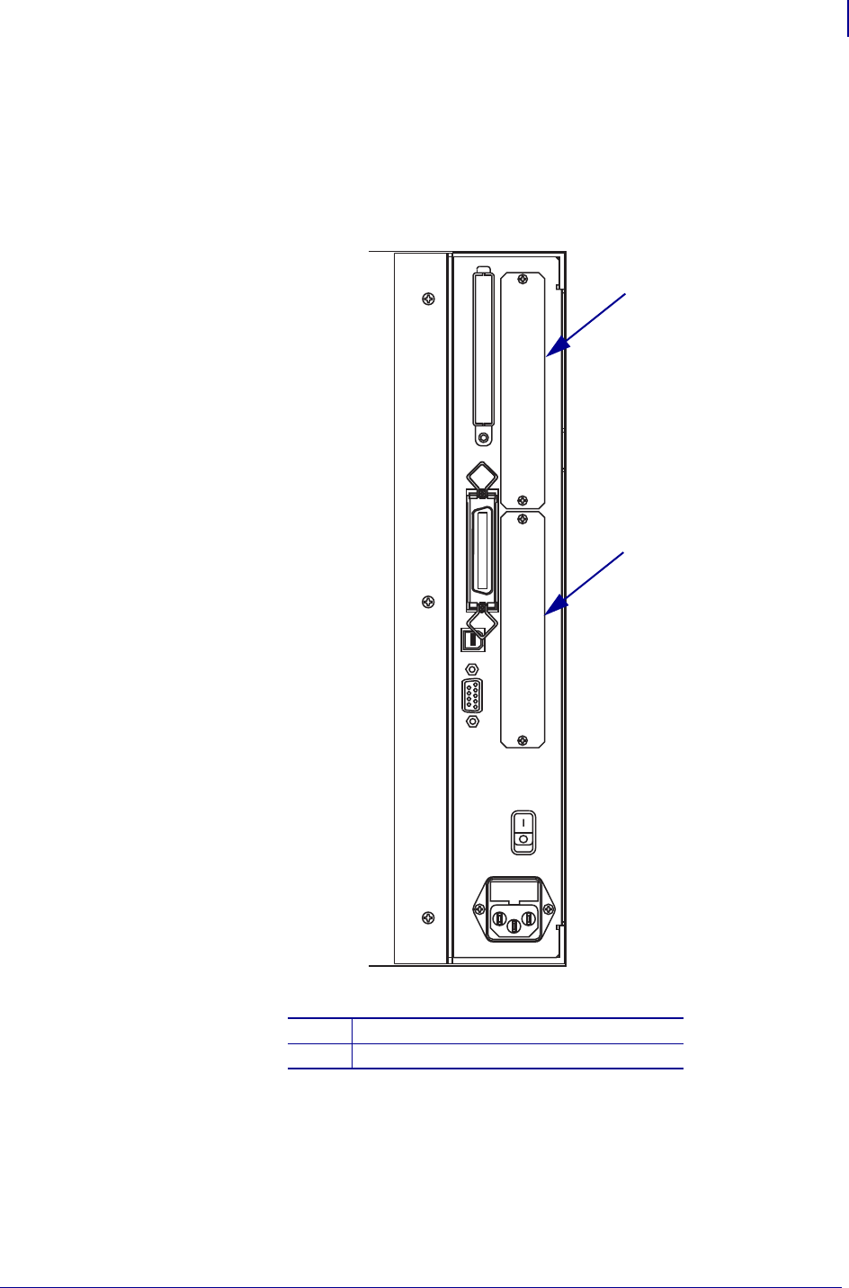
Remove Option Boards
In order to install the Internal Wireless Plus Print Server, you must remove any option boards
located in either of the slots shown below. See Figure 3.
Figure 3 • Option Board Locations
1 Applicator option
2Twinax, Coax, and Print Server options
1
2
ZebraNet Internal Wireless Plus Print Server for 105SL and XiIIIPlus
Remove the Existing Internal Wireless Plus, Wireless Plus, or PCMCIA Option Board Assembly
6
14551L-001 Rev. A 2/14/08
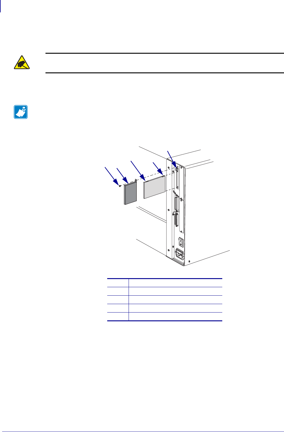
Remove the Existing Internal Wireless Plus, Wireless
Plus, or PCMCIA Option Board Assembly
1. See Figure 4. Check the rear panel for the RF card cover. Remove the mounting screw and
the cover, and then eject either the wireless card or the memory card.
Figure 4 • RF Card and Cover
Caution • Observe proper electrostatic safety precautions when handling any
static-sensitive components such as circuit boards and printheads.
Note • See Figure 2. If you have a PCMCIA Option Board and PCMCIA card, your
printer will have a metal option card shield instead of the plastic RF cover.
1RF card cover mounting screw
2RF card cover (plastic)
3Wireless option card
4Notch
5Card eject button
12
34
5
7
ZebraNet Internal Wireless Plus Print Server for 105SL and XiIIIPlus
Remove the Existing Internal Wireless Plus, Wireless Plus, or PCMCIA Option Board Assembly
2/14/08 14551L-001 Rev. A
2. What type of option board do you currently have?
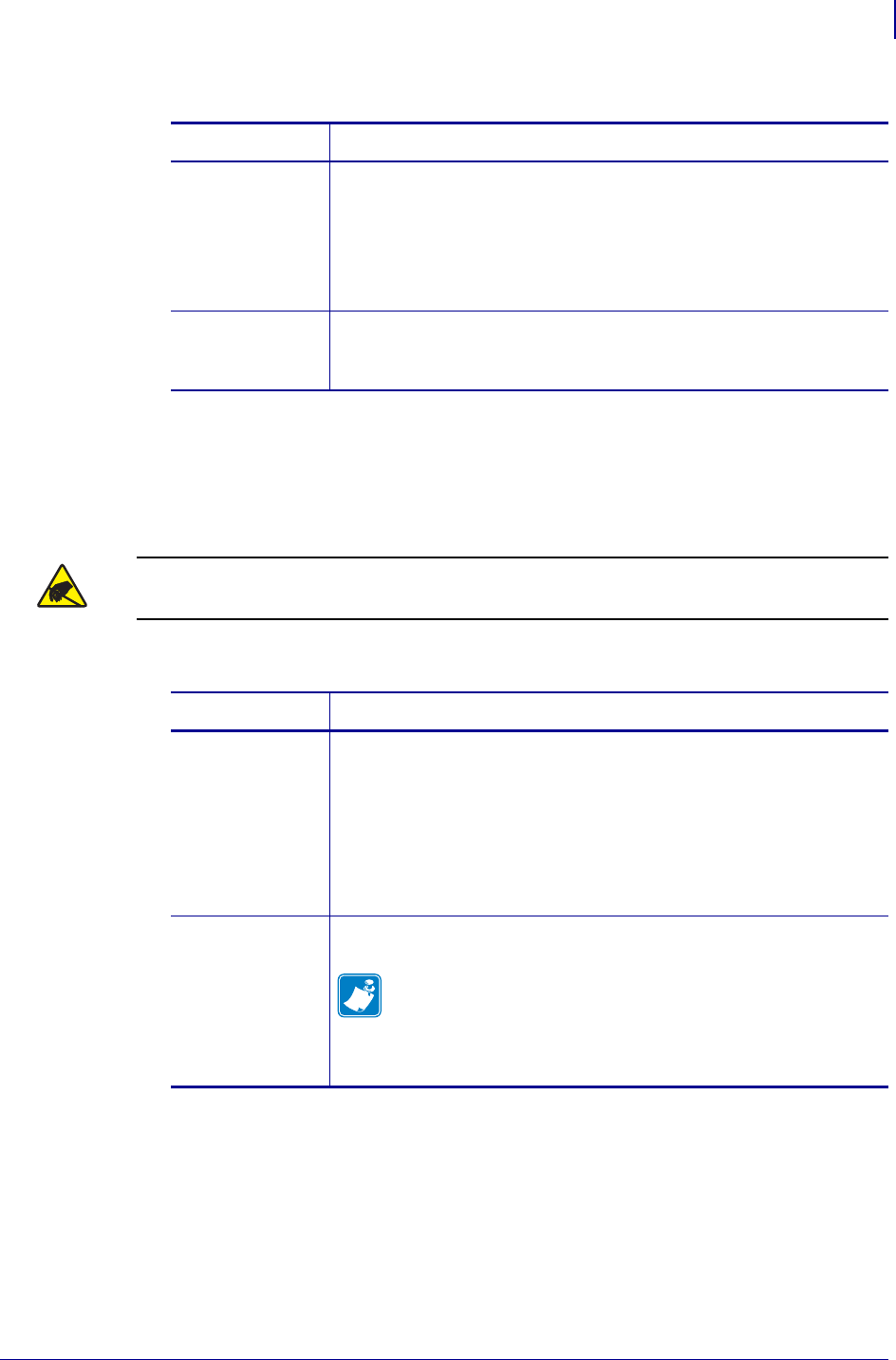
Remove the PCMCIA/Wireless Standoffs
The 105SL and the XiIIIPlus have used two different means of securing the PCMCIA/wireless
board to the main logic board (MLB).
1. See Figure 5. How does your PCMCIA/wireless board connect to the MLB?
If you have… Then…
PCMCIA,
Wireless
PrintServer, or
Wireless Plus
Print Server
board
Continue to Remove the PCMCIA/Wireless Standoffs on page 7.
Internal Wireless
Plus Print Server
board
Go to Remove the Internal Wireless Plus Print Server Board
on page 8.
Caution • Observe proper electrostatic safety precautions when handling any
static-sensitive components such as circuit boards and printheads.
If you have… Then…
Two plastic
locking standoffs a. Remove the screw securing the PCMCIA/wireless board to a
metal standoff on the printer chassis.
b. Disconnect the PCMCIA/wireless board from two plastic
standoffs.
c. Gently pull the PCMCIA/wireless board away from the MLB to
disconnect the two connectors, P24 and P23, on the MLB.
d. Continue to Remove the MLB on page 9.
Two screws,
spacers, and nuts a. Remove the screw securing the PCMCIA/wireless board to a
metal standoff on the printer chassis.
Note • You must remove the MLB and PCMCIA/wireless
boards from the printer together, and then separate them.
You will complete this in the next section.
b. Continue to Remove the MLB on page 9.
ZebraNet Internal Wireless Plus Print Server for 105SL and XiIIIPlus
Remove the Existing Internal Wireless Plus, Wireless Plus, or PCMCIA Option Board Assembly
8
14551L-001 Rev. A 2/14/08
Figure 5 • Standoffs
Remove the Internal Wireless Plus Print Server Board
1. From the back of the printer, unscrew the RF antenna.
2. Remove the nut and washer from the RF connector.
3. Remove the top mounting screw securing the Internal Wireless Plus bracket.
4. Remove the bracket and set aside.
1Standoff to main frame 4Mounting screws (2)
2Plastic standoffs (2) 5Spacers (2)
3Mounting screw 6Threaded spacers (2)
1
1
2
3
3
45
6
PCMCIA
PCMCIA
MLB
MLB
Caution • Observe proper electrostatic safety precautions when handling any
static-sensitive components such as circuit boards and printheads.
9
ZebraNet Internal Wireless Plus Print Server for 105SL and XiIIIPlus
Remove the MLB
2/14/08 14551L-001 Rev. A
Remove the MLB
1.
Connect yourself to an antistatic device.
2. What printer do you have?
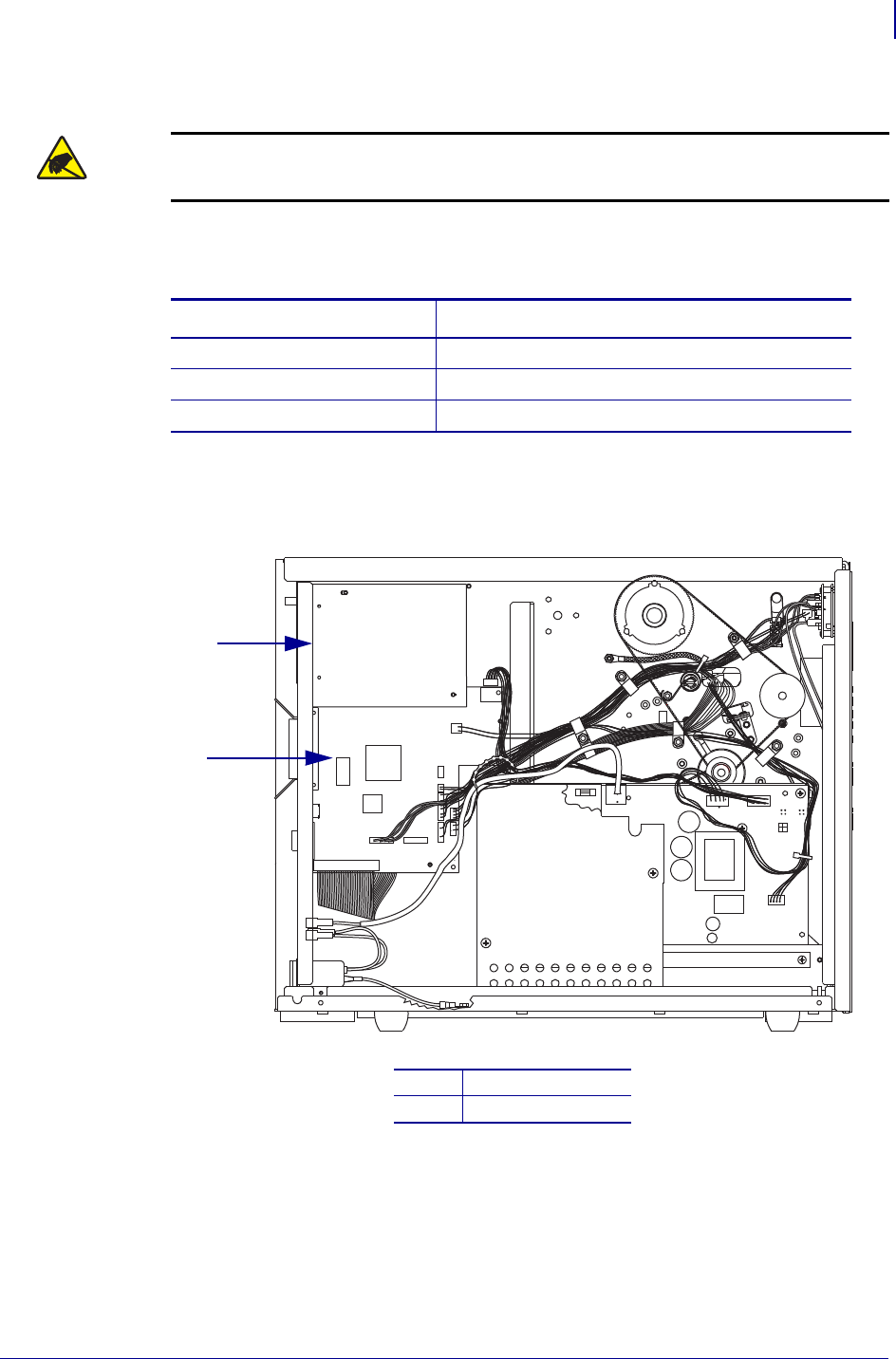
3. Unplug the ribbon cable and small wire connectors. Note the wire connector positions.
Figure 6 • 105SL Main Logic Board Location
Caution • Observe proper electrostatic safety precautions when handling
static-sensitive components such as circuit boards and printheads.
If you have a… Then…
105SL See Figure 6 and Figure 7.
110XiIIIPlus See Figure 8.
All other XiIIIPlus models See Figure 9.
1PCMCIA board
2Main logic board
1
2
ZebraNet Internal Wireless Plus Print Server for 105SL and XiIIIPlus
Remove the MLB
10
14551L-001 Rev. A 2/14/08
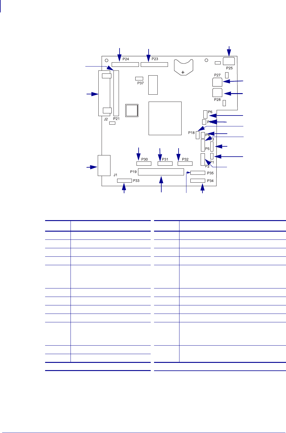
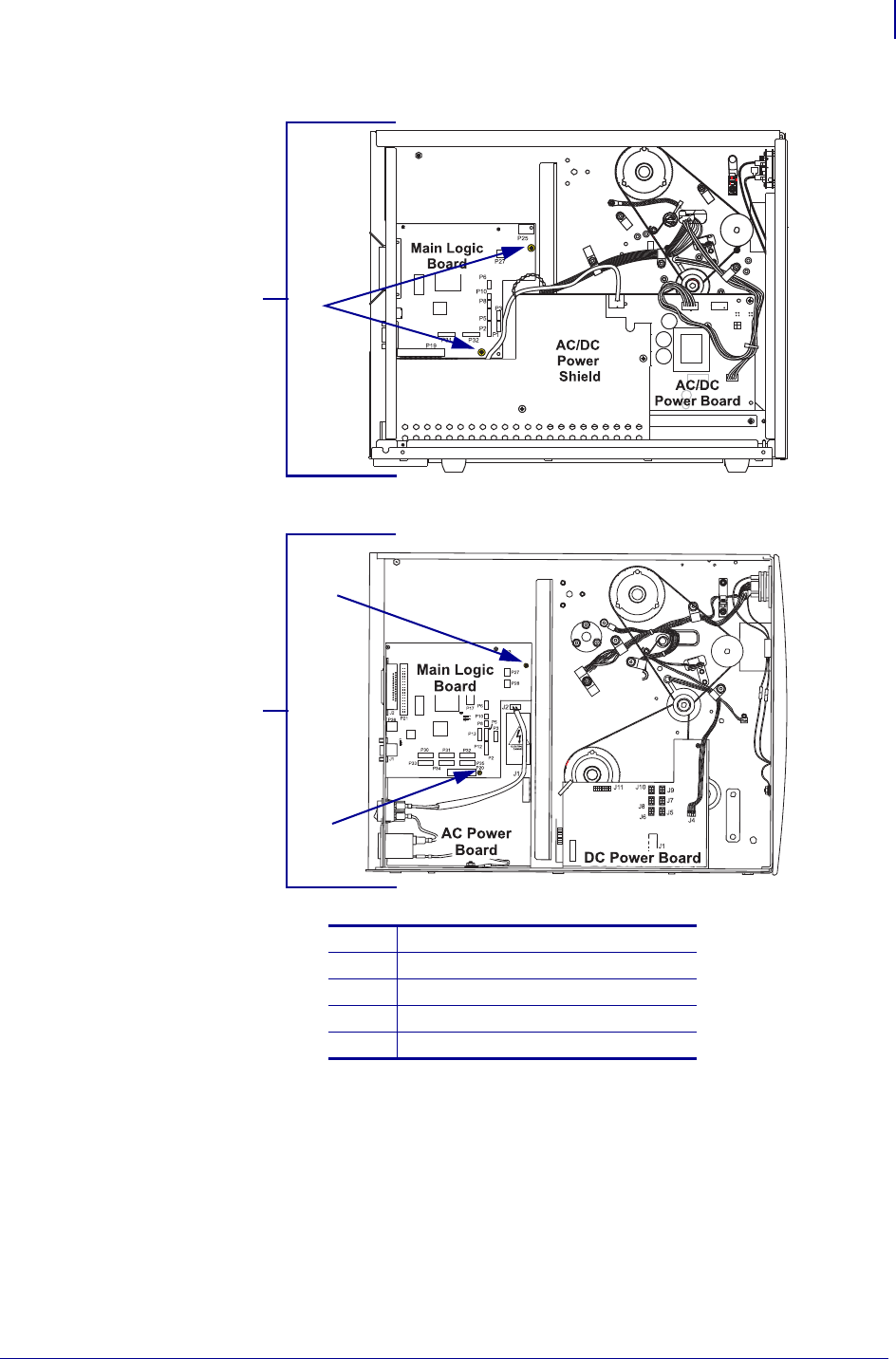
Figure 7 • 105SL Main Logic Board Location and Interconnection
Table 2 • 105SL Main Logic Board Location and Interconnection
Conn. Description Conn. Description
J1 Serial port P23 PCMCIA board connector
J2 Parallel port P24 PCMCIA board connector
P1 Lower take-label sensor P25 Power-in
P2 Upper take-label sensor P27 LCD display control board power
P3 Head-open sensor P28 DC Power
(Only available on the Custom 4MB
board)
P5 Ribbon sensor P30 SPI connector*
P6 Reflective media sensor P31 SPI connector*
P8 Transmissive media sensor P32 SPI connector LCD display board*
P10 Transmissive media sensor P33 SPI connector cutter board*
P18 Custom interface connector
(Only available on the
Custom 4MB board)
P34 SPI connector DC power supply J11*
P19 Printhead data P35 SPI connector*
P21 Internal parallel connector
*SPI—Serial Peripheral Interface
P27
P6
P10
P5
P8
P3
P1
P2
P34
P35
P19P33
P30 P31 P32
J1
P21
J2
P24 P23 P25
P28
P18
11
ZebraNet Internal Wireless Plus Print Server for 105SL and XiIIIPlus
Remove the MLB
2/14/08 14551L-001 Rev. A
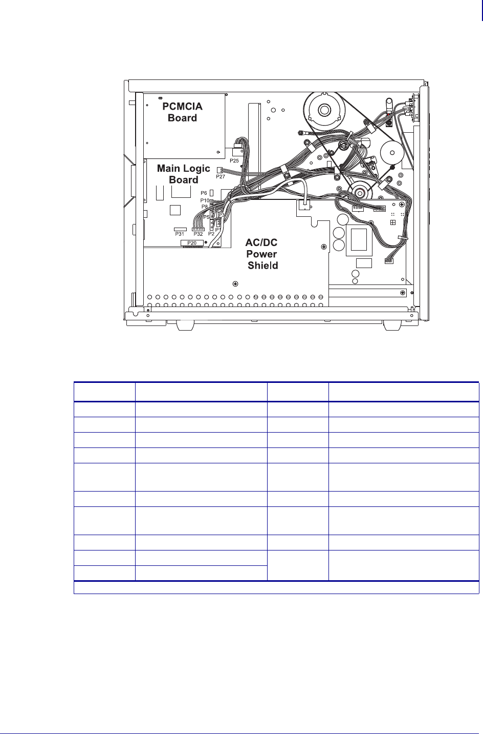
Figure 8 • Wireless PCMCIA and Main Logic Board Locations—
110XiIIIPlus Models Only
Table 3 • 110XiIIIPlus Models Only
Connector Description Connector Description
P1 Lower take-label sensor P24 PCMCIA board connector
P2 Upper take-label sensor P27 LCD display control board power
P3 Head-open sensor P30 SPI connector*
P5 Ribbon sensor P31 SPI connector*
P6 Reflective media sensor P32 SPI connector LCD display
board*
P8 Transmissive media sensor P33 SPI connector cutter board*
P10 Transmissive media sensor P34 SPI connector DC power supply
J11*
P20 Printhead data P35 SPI connector*
P21 Internal parallel connector P36 USB port
P23 PCMCIA board connector
*SPI—Serial Peripheral Interface
ZebraNet Internal Wireless Plus Print Server for 105SL and XiIIIPlus
Remove the MLB
12
14551L-001 Rev. A 2/14/08
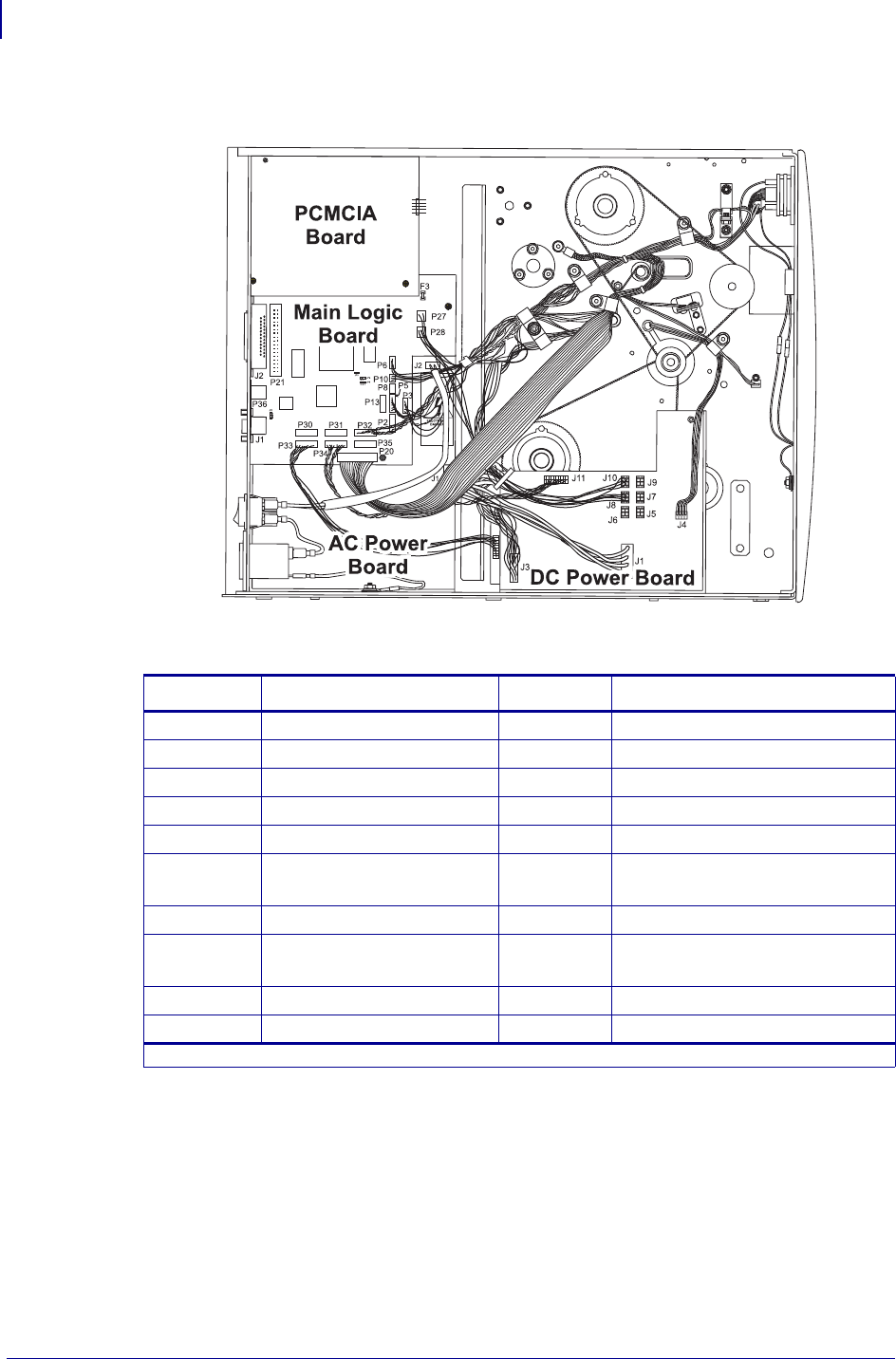
Figure 9 • Wireless PCMCIA and Main Logic Board Locations—
All Models Except 110XiIIIPlus
Table 4 • All Models Except 110XiIIIPlus
Connector Description Connector Description
P1 Lower take-label sensor P24 PCMCIA board connector
P2 Upper take-label sensor P27 LCD display control board power
P3 Head-open sensor P28 DC power supply J10
P5 Ribbon sensor P30 SPI connector*
P6 Reflective media sensor P31 SPI connector*
P8 Transmissive media sensor P32 SPI connector LCD display
board*
P10 Transmissive media sensor P33 SPI connector cutter board*
P20 Printhead data P34 SPI connector DC power supply
J11*
P21 Internal parallel connector P35 SPI connector*
P23 PCMCIA board connector P36 USB port
*SPI—Serial Peripheral Interface
13
ZebraNet Internal Wireless Plus Print Server for 105SL and XiIIIPlus
Remove the MLB
2/14/08 14551L-001 Rev. A
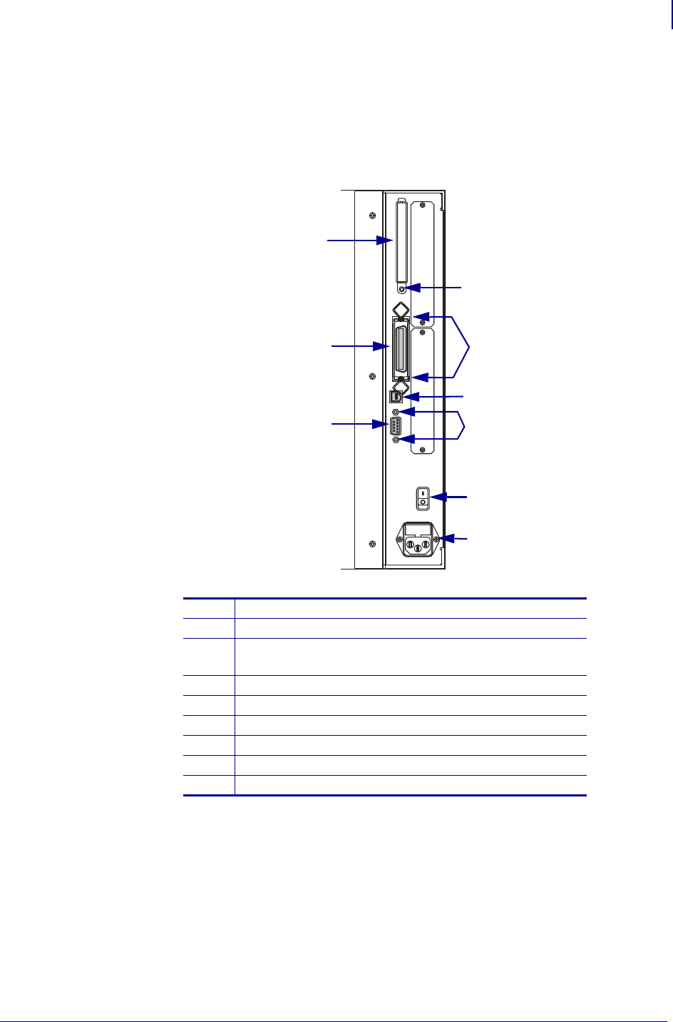
4. See Figure 10. At the rear panel, remove the two screws that secure the 36-pin parallel
port connector.
5. Remove the two standoffs and washers securing the 9-pin serial port connector.
Figure 10 • Rear View of Rear Panel
1RF cover mounting screw
2Parallel interface mounting screws (2)
3USB connector
(only available on XiIIIPlus models)
4DB-9 serial interface mounting studs and washers (2)
5AC power on/off switch
6AC power cable connection
7DB-9 serial interface connector
8Parallel interface connector
9RF cover
2
3
4
5
6
7
8
1
9
ZebraNet Internal Wireless Plus Print Server for 105SL and XiIIIPlus
Remove the MLB
14
14551L-001 Rev. A 2/14/08
6. What printer do you have?
7. On the electronics side of the printer, remove the MLB by removing the mounting screw
in the upper right and the mounting screw (or nut) at the bottom right.
8. To remove the MLB/PCMCIA assembly, pull out the top of the assembly and guide its
three (serial, parallel, and RF) connectors out of the rear panel openings.
9. Place the assembly on an antistatic mat.
10. If your boards were connected using plastic locking standoffs, remove and discard the
standoffs.
11. If your boards are connected using screws, spacers and nuts, hold the nut on the back of
the MLB while removing the screw from the front of the PCMCIA board. Repeat for both
screws, standoffs, and nuts.
12. Separate the MLB and PCMCIA boards.
13. Continue with Install the New Internal Wireless Plus and MLB Boards on page 16.
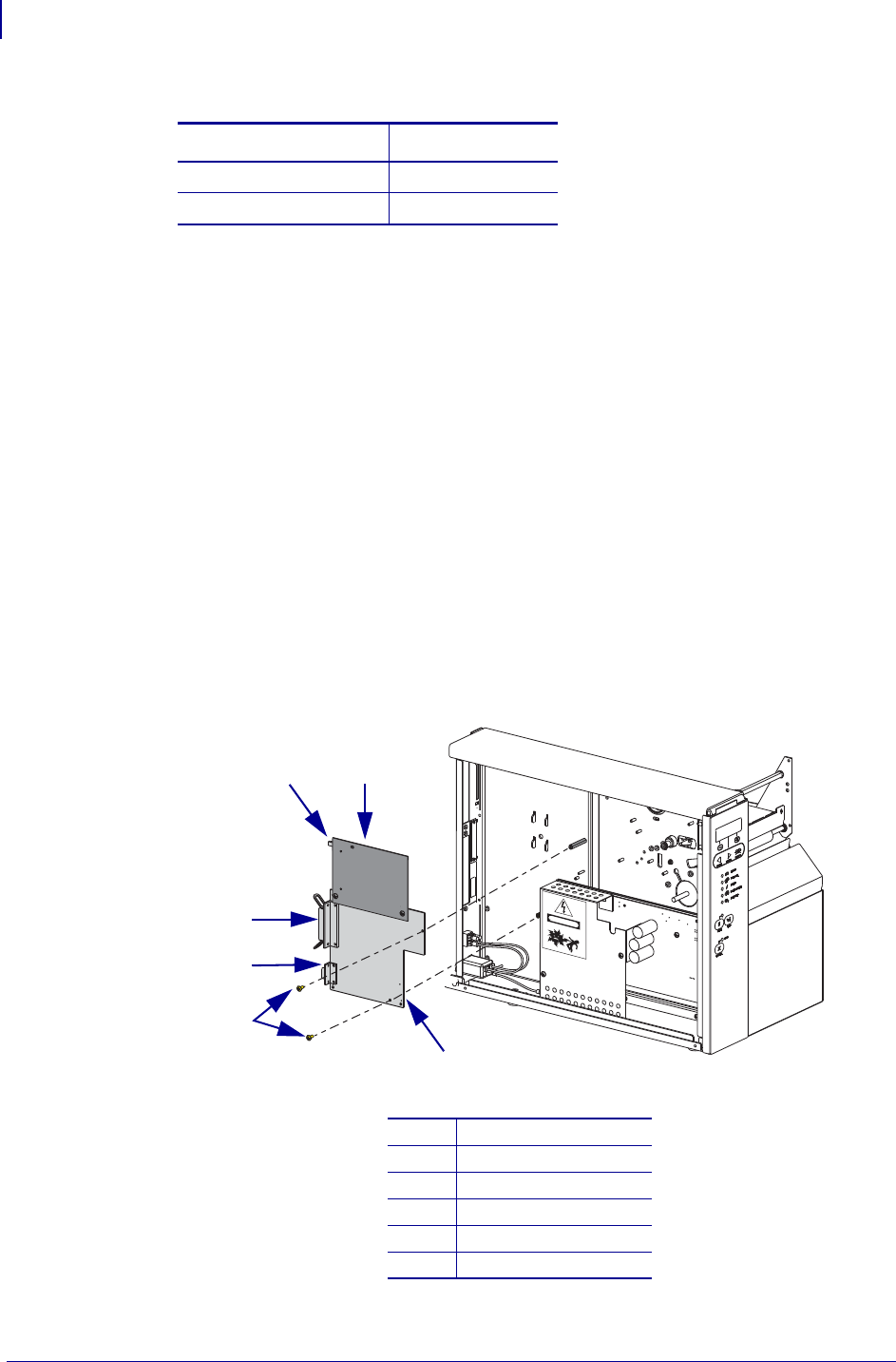
Figure 11 • Remove the 105SL PCMCIA Board and Main Logic Board
If you have a… Then…
105SL a. See Figure 11.
All XiIIIPlus models a. See Figure 12.
1PCMCIA board
2RF antenna
3Parallel port
4Serial port
5Mounting screws (2)
6Main logic board
DANGER
HIGH VOLTAGE
1
2
3
4
5
6
15
ZebraNet Internal Wireless Plus Print Server for 105SL and XiIIIPlus
Remove the MLB
2/14/08 14551L-001 Rev. A
Figure 12 • Remove the XiIIIPlus MLB
A110XiIIIPlus
BAll models except 110XiIIIPlus
1Mounting screws (2)
2Mounting screw
3Mounting nut
1
2
3
A
B
ZebraNet Internal Wireless Plus Print Server for 105SL and XiIIIPlus
Install the New Internal Wireless Plus and MLB Boards
16
14551L-001 Rev. A 2/14/08
Install the New Internal Wireless Plus and MLB Boards
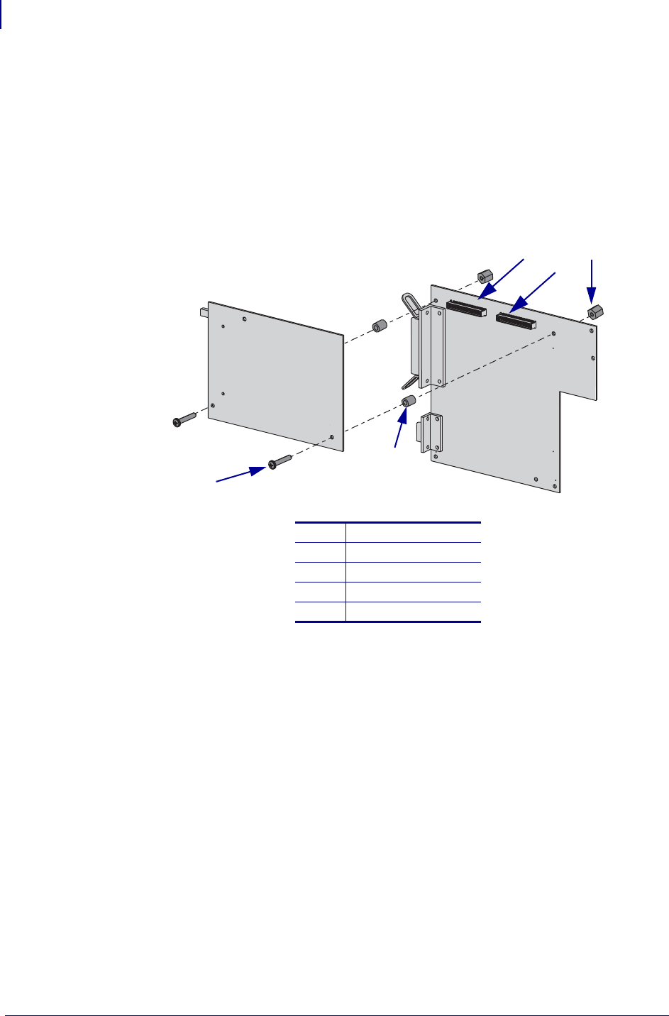
1. See Figure 13. Align the two connectors on the internal wireless plus board with P23 and
P24 on the MLB and then push them together.
2. Slide one of the new spacers between the internal wireless plus board and the MLB at
either one of the mounting holes.
Figure 13 • Install New Spacers
3. Insert one of the screws through the mounting hole in the internal wireless plus board,
spacer, and MLB.
4. Secure the screw with one of the plastic nuts.
5. Repeat step 2, step 3, and step 4 for the other mounting hole.
6. Ensure that the internal wireless plus board is seated into the MLB connectors, P23 and
P24.
7. See Figure 14. Starting with the top edge of the internal wireless plus board assembly,
install the assembly using the hardware previously removed.
Ensure that the connectors (RF, parallel, and serial) align with the appropriate openings in
the rear panel.
1P24 connector
2P23 connector
3Nuts (2)
4Spacers (2)
5Screws (2)
PCMCIA
MLB
1
2
3
5
4
17
ZebraNet Internal Wireless Plus Print Server for 105SL and XiIIIPlus
Install the New Internal Wireless Plus and MLB Boards
2/14/08 14551L-001 Rev. A
Figure 14 • Install the Internal Wireless Plus Print Server Board and MLB
8. See Figure 10 on page 13. Reinstall the screws and studs for the serial and parallel
interface connectors.
9. See Figure 6 on page 9 and Table 2 on page 10. Reconnect all ribbon and small wire
connections to the MLB.
10. See Figure 3 on page 5. Reinstall any other option boards previously removed.
1Internal wireless plus print server board
2Wireless mounting screw
3Wireless-to-MLB mounting screws (2)
4Parallel interface mounting screws (2)
5Wireless-to-MLB spacers (2)
6Serial interface mounting studs (2)
7Serial interface washers (2)
8MLB mounting screws (2)
9MLB
10 Cast boss
1
2
3
4
5
6
7
8
10
9
4
5

ZebraNet Internal Wireless Plus Print Server for 105SL and XiIIIPlus
Install the Bracket and External Antenna
18
14551L-001 Rev. A 2/14/08
Install the Bracket and External Antenna
1. From the back of the printer, remove the sticker located alongside of the option card slot.
2. Using isopropyll alcohol, remove all of the sticker’s glue.
3. Place a washer and a nut on the RF connector.
4. Insert the bottom edge of the bracket in the small slot below the option card slot.
5. Fasten the top of the bracket into place using one of the screws provided in the kit.
6. To install the external antenna, screw the antenna on to the RF connector extending out
from the back plate of the printer.
Reinstall the Electronics Cover
1. See Figure 2 on page 4. Reinstall the electronics cover by lowering the cover so the lip
goes into the channel on the top of the printer.
2. Secure the cover by reinstalling the two screws on the bottom of the cover.
3. Reconnect the data cables and the AC power cord.
Resume Printer Operation
1. Refer to the Wireless User Guide to configure the Internal Wireless Plus Print Server for
operation.
2. Turn on (l) the printer.
After You Complete the Installation
Firmware
After you have completed this installation, you must download firmware version V60.16.x (or
later) a second time from: www.zebra.com/firmware.
19
ZebraNet Internal Wireless Plus Print Server for 105SL and XiIIIPlus
After You Complete the Installation
2/14/08 14551L-001 Rev. A
Attach Labels
1. Did you receive one or more labels in your kit?
2. See Figure 15. Examine the labels included with the kit.
There may be several labels included with your kit.
If… Then…
Yes Continue with step 2.
No Skip to step 4.
If you have labels… Then…
With your printer model
in the lower right-hand
corner
a. See Figure 16. Remove all of the old small plastic
labels affixed to the outside of your printer.
Important • Do not remove the electrical ratings
label, also known as the model plate. The model
plate contains essential user information.
b. See Figure 15. Remove the backing for all of the labels
for your specific printer.
c. See Figure 16. Affix the new printer labels in the area
near the model plate.
d. Continue with step 3.
Blank in the lower right-
hand corner a. See Figure 16. Remove all of the old small plastic
labels affixed to the outside of your printer.
Important • Do not remove the electrical ratings
label, also known as the model plate. The model
plate contains essential user information.
b. See Figure 15. For all labels that are blank in the corner,
remove the backing for these labels.
c. See Figure 16. Affix the new printer labels in the area
near the model plate.
d. Continue with step 3.

ZebraNet Internal Wireless Plus Print Server for 105SL and XiIIIPlus
After You Complete the Installation
20
14551L-001 Rev. A 2/14/08
Figure 15 • Sample Labels
Figure 16 • Label Location
3. Discard any additional labels included in the kit.
4. The installation is complete.
With Printer Model
2
1
Without Printer Model
1Printer model
2No printer model
1Affix labels here
2Model plate
1
2

Compliance Information
Compliance Information
Compliance Information
FCC Compliance Statement
This device complies with Part 15 rules. Operation is subject to the following two conditions:
1. This device may not cause harmful interference, and
2. This device must accept any interference received, including interference that may cause
undesired operation.
The user is cautioned that any changes or modifications not expressly approved by Zebra
Technologies could void the user’s authority to operate the equipment. To ensure compliance,
this printer must be used with Shielded Communication Cables.
FCC Radiation Exposure Statement
This equipment complies with FCC radiation exposure limits set forth for an uncontrolled
environment. This equipment should be installed and operated with minimum distance 20cm
between the radiator and your body.
This transmitter must not be co-located or operating in conjunction with any other antenna or
transmitter.
Canadian DOC Compliance Statement
This Class B digital apparatus complies with Canadian ICES-003.
Cet appareil numérique de la classe B est conforme à la norme NMB-003 du Canada.
© 2008 ZIH Corp. All product names and numbers are Zebra
trademarks, and Zebra and the Zebra logo are registered
trademarks of ZIH Corp. All rights reserved.
Printed on
chlorine-free
recycled paper.
ZebraNet® Internal Wireless Plus Print Server for
S4M
Installation Instructions
This kit includes the parts and documentation necessary to install the ZebraNet® Internal
Wireless Plus Print Server into the S4M™ printer. Read these instructions thoroughly before
performing this procedure.
Prepare for Installation
Parts List
Table 1 • Kit Parts List
3Item Qty Part Number Description
Ref 1MInternal Wireless Plus Print Server Option Maintenance
Kit
1129883-001 Internal Wireless Plus PC Board
2139538 Antenna
32 Screw, M3
41 Standoff
Bold = Part available for purchase.
Italic = Part not available for purchase, listed and shown for reference only.

ZebraNet® Internal Wireless Plus Print Server for S4M
Prepare for Installation
2
14550L-001 Rev. A 02/14/2008
Figure 1 • Kit Contents
Reference Materials
•ZebraNet
® Wireless User Guide
•S4M User CD
• S4M User Guide
• S4M Quick Reference Guide
• S4M Maintenance Manual (contact your authorized Zebra reseller for purchasing
information).
Tools Required
Before You Begin
Before starting this installation, you must download firmware version V53.16.x (or later)
from: www.zebra.com/firmware.
1
23
4
Tools • You need these tools to complete this procedure:
Phillips Screwdriver Set
Metric Nutdriver Set
Antistatic Wriststrap and Mat
3
ZebraNet® Internal Wireless Plus Print Server for S4M
Remove the Electronics Cover
02/14/2008 14550L-001 Rev. A
Remove the Electronics Cover
1.
Turn off (O) the printer and disconnect the AC power cord and all data cables.
2. See Figure 2. Remove the electronics cover mounting screw and washer and then close the
media door.
Figure 2 • Remove the Mounting Screw
3. See Figure 3. Remove the four remaining mounting screws securing the electronics cover.
Note • Retain all parts removed during disassembly, unless otherwise directed.
Caution • Turn off (O) the printer and disconnect it from the power source before
performing the following procedure.
1Media door
2Electronics cover upper flange
3Electronics cover mounting screw
4Washer
1
2
3
4
ZebraNet® Internal Wireless Plus Print Server for S4M
Remove the Electronics Cover
4
14550L-001 Rev. A 02/14/2008
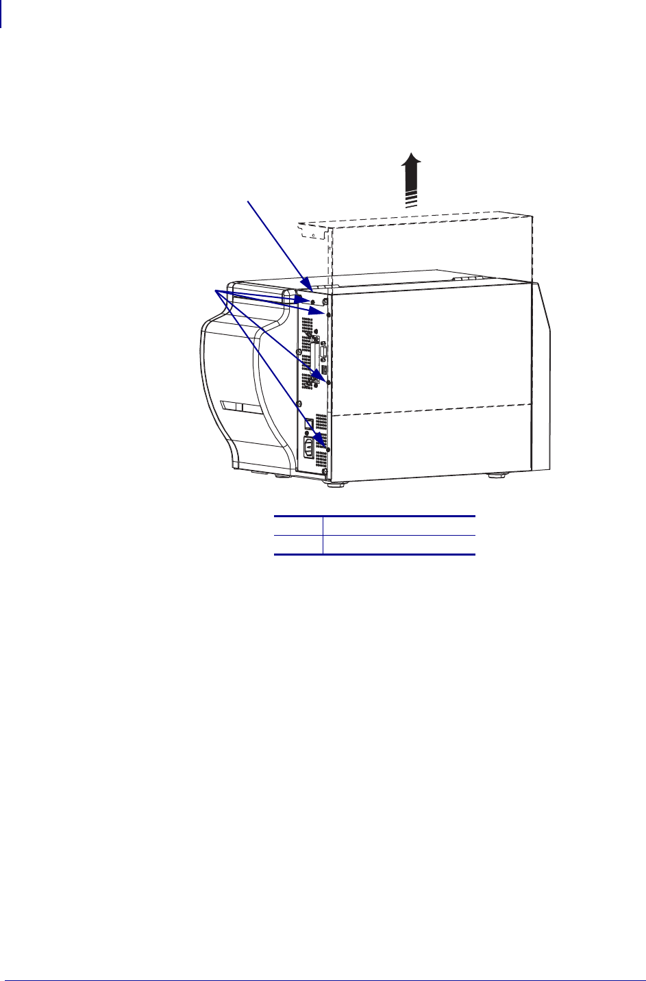
4. Remove the electronics cover by lifting straight up on the bottom lip of the electronics
cover.
Figure 3 • Remove the Electronics Cover
1Electronics cover
2Mounting screws (4)
2
1
5
ZebraNet® Internal Wireless Plus Print Server for S4M
Remove the Main Logic Board
02/14/2008 14550L-001 Rev. A
Remove the Main Logic Board
1.
Connect yourself to an antistatic device.
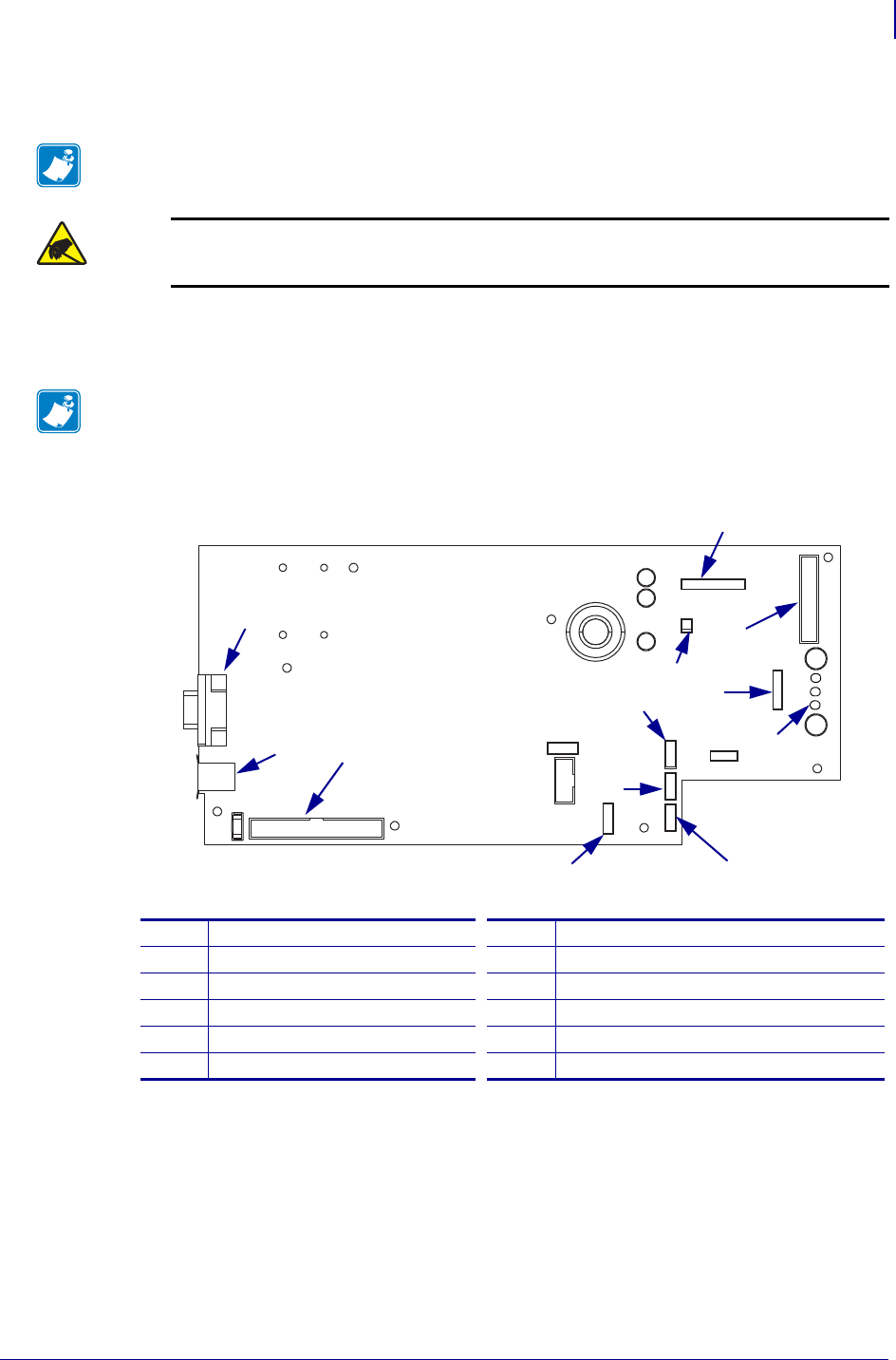
2. See Figure 4. Remove all cables from the main logic board.
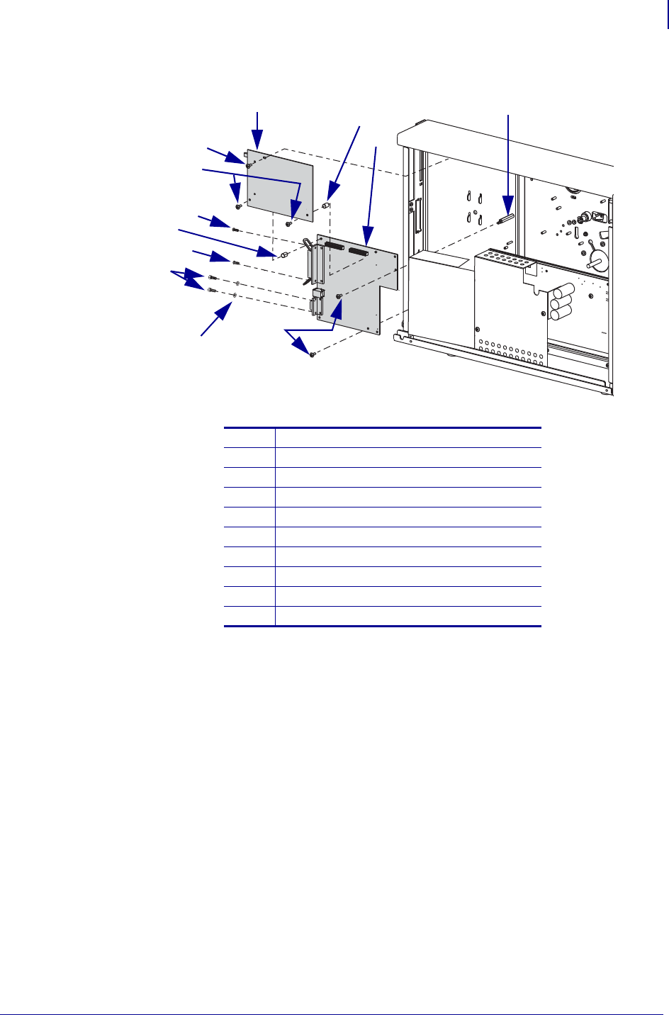
Figure 4 • Remove the Main Logic Board Connections
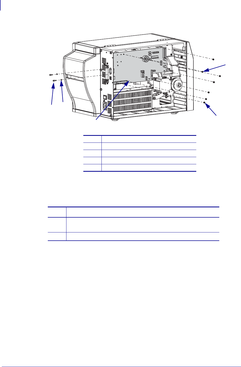
3. See Figure 5. Remove the six screws and one nut securing the main logic board to the
frame of the printer.
4. Remove the two studs and washers securing the serial port connector to the back of the
printer.
Note • Retain all parts removed during disassembly, unless otherwise directed.
Caution • Observe proper electrostatic safety precautions when handling
static-sensitive components such as circuit boards and printheads.
Note • Take note of the location of all connectors on the main logic board.
1Printhead data (J3) 7Transmissive sensor (P9)
2Power-in (J8) 8Reflective sensor (P7)
3Front panel (J2) 9Take-label sensor (J19)
4Stepper motor (J9) 10 Communication expansion port (J17)
5Booster board (J7) 11 USB (J14)
6Head open ribbon sensor (P4) 12 Serial port (J10)
F6
L
F
1A
1
2
3
4
5
6
7
8
10
11
12
9
ZebraNet® Internal Wireless Plus Print Server for S4M
Remove the Main Logic Board
6
14550L-001 Rev. A 02/14/2008
Figure 5 • Remove the Main Logic Board
5. Remove the main logic board from the printer.
6. Is there a ZebraNet Internal 10/100 PrintServer, Wireless Plus Print Server, or Parallel
Option Board already installed on the printer?
1Main logic board nut (1)
2Main logic board mounting screws (6)
3Main logic board
4Serial port mounting studs (2)
5Parallel port mounting screws (2)
If… Then…
No Go to Install the New Internal Wireless Plus Print Server Board
on page 9.
Yes Continue with Remove the Existing Option Board on page 7.
2
3
1
4
5
7
ZebraNet® Internal Wireless Plus Print Server for S4M
Remove the Existing Option Board
02/14/2008 14550L-001 Rev. A
Remove the Existing Option Board
1. See Figure 6 or Figure 7. Remove the two screws securing the parallel port connector, the
ZebraNet Internal 10/100 PrintServer, Wireless Plus Print Server, or the Wireless Print
Server to the back of the printer.
2. Which communication option do you currently have?
Remove the ZebraNet Internal 10/100 PrintServer Board or the
Parallel Option Board
1. See Figure 6. Remove the standoff and then the ZebraNet Internal 10/100 PrintServer or
Parallel Option Board from the printer.
Figure 6 • Remove the ZebraNet Internal 10/100 PrintServer Board
or the Parallel Option Board
2. Proceed to Install the New Internal Wireless Plus Print Server Board on page 9.
If you have a… Then…
ZebraNet Internal 10/100
PrintServer Board or a Parallel
Port Option
Continue with Remove the ZebraNet Internal 10/100
PrintServer Board or the Parallel Option Board
on page 7.
Wireless Plus Print Server Go to Remove the Wireless Plus Print Server Board
on page 8.
1Standoff
2ZebraNet Internal 10/100 PrintServer board or Parallel Port
3Mounting screws (2)
1
2
3
ZebraNet® Internal Wireless Plus Print Server for S4M
Remove the Existing Option Board
8
14550L-001 Rev. A 02/14/2008
Remove the Wireless Plus Print Server Board
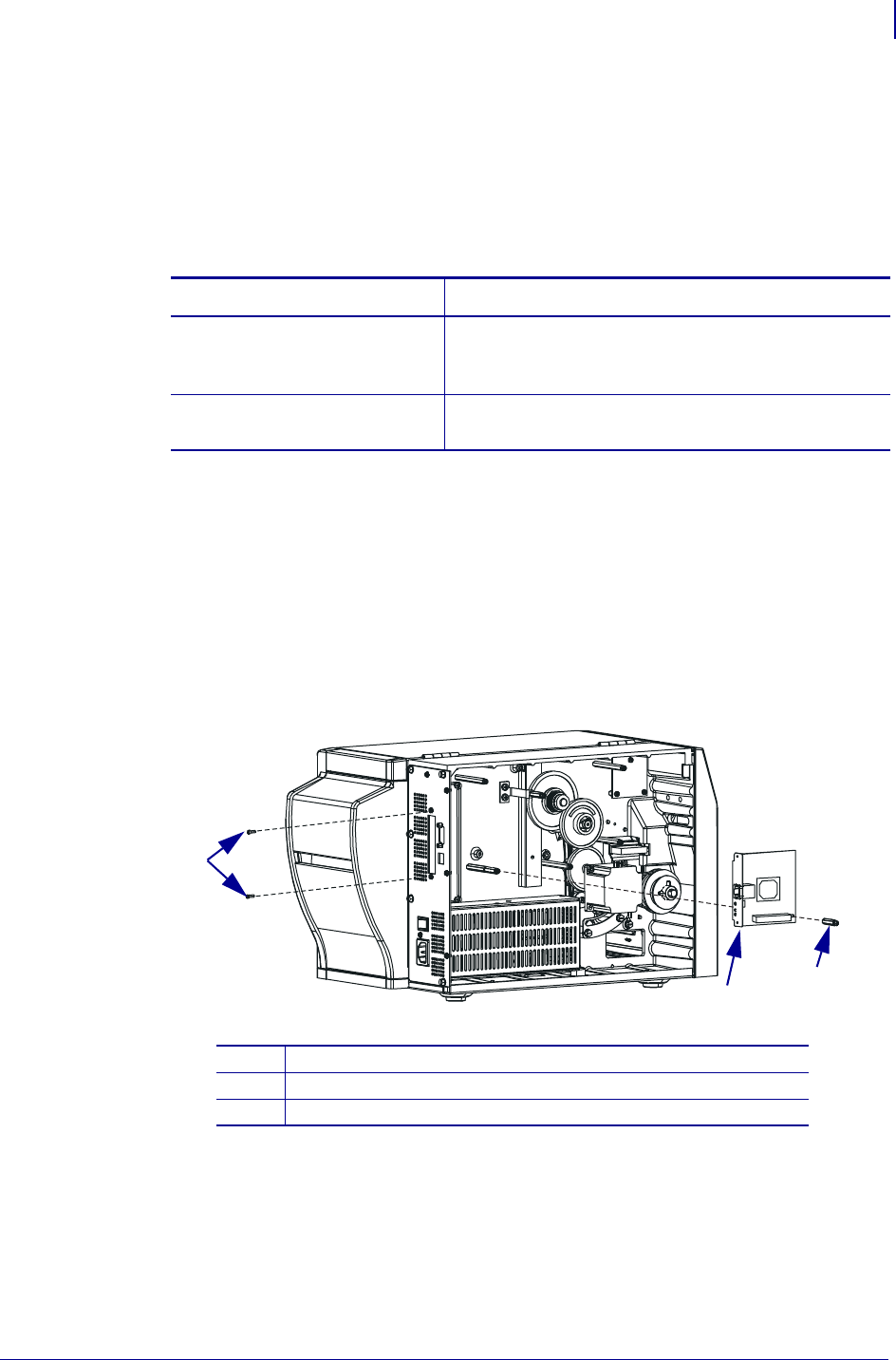
1. See Figure 7. Remove the two standoffs and mounting screws from the wireless plus print
server board.
2. Remove the wireless plus print server board from the printer.
Figure 7 • Remove the Wireless Print Server Board
3. Go to Install the New Internal Wireless Plus Print Server Board on page 9.
1Standoffs (2)
2Wireless print server board
3Mounting screws (2)
1
2
3
9
ZebraNet® Internal Wireless Plus Print Server for S4M
Install the New Internal Wireless Plus Print Server Board
02/14/2008 14550L-001 Rev. A
Install the New Internal Wireless Plus Print Server
Board
1. Are you installing the Internal Wireless Plus Print Server for the first time?
Figure 8 • Remove the Standoffs
(Revise graphic for Internal Wireless Plus Board. This is showing the PSII board.)
2. Install the board using the standoff and mounting screws included in this kit.
3. Install the 40-pin cable that will go to the main logic board.
If… Then…
No Go to step 2.
Yes a. See Figure 8. Remove the two short standoffs shown.
Note • Depending on your printer, you may have a cast boss instead of
a second standoff attached to the main frame.
b. Remove and discard the two washers; they are used as spacers when there is
no option board installed.
c. Continue with step 2.
1Internal wireless plus print server board
2Standoff
3Mounting screws (2)
1
2
3
3

ZebraNet® Internal Wireless Plus Print Server for S4M
Reinstall the Main Logic Board
10
14550L-001 Rev. A 02/14/2008
Reinstall the Main Logic Board
1. See Figure 5 on page 6. Install the main logic board in the printer using the six screws and
one nut removed previously.
2. From the back panel of the printer, reinstall the two screws and washers securing the
Internal Wireless Plus Print Server board and the two studs and washers securing the serial
port to the back panel.
3. See Figure 4 on page 5. Reinstall all the cables previously removed from the main logic
board.
Visually inspect and ensure the cables are in their proper location and seated in the
connectors.
Install the External Antenna
1. To install the external antenna, screw the antenna on to the RF connector extending out
from the back panel of the printer.
Resume Operations
1. See Figure 3 on page 4. Install the cover by aligning it and sliding down, ensuring the
lower tabs are inside the base and the upper flanges are between the main frame and the
media door.
2. Install the four mounting screws on the back of the printer.
3. See Figure 2 on page 3. Open the media door and install the mounting screw and washer
to secure the electronics cover.
Install the Electronics Cover
1. Reinstall the media and ribbon.
2. Reconnect AC power cord and data cables.
3. Turn on (l) the printer.
11
ZebraNet® Internal Wireless Plus Print Server for S4M
After You Complete the Installation
02/14/2008 14550L-001 Rev. A
After You Complete the Installation
Firmware
After you have completed this installation, you must download firmware version V53.16.x (or
later) a second time from: www.zebra.com/firmware.
Attach Labels
1. Did you receive one or more labels in your kit?
2. See Figure 9. Examine the labels included with the kit.
There may be several labels included with your kit.
If… Then…
Yes Continue with step 2.
No Skip to step 4.
If you have labels… Then…
With your printer model
in the lower right-hand
corner
a. See Figure 10. Remove all of the old small plastic
labels affixed to the outside of your printer.
Important • Do not remove the electrical ratings
label, also known as the model plate. The model
plate contains essential user information.
b. See Figure 9. Remove the backing for all of the labels
for your specific printer.
c. See Figure 10. Affix the new printer labels in the area
near the model plate.
d. Continue with step 3.
Blank in the lower right-
hand corner a. See Figure 10. Remove all of the old small plastic
labels affixed to the outside of your printer.
Important • Do not remove the electrical ratings
label, also known as the model plate. The model
plate contains essential user information.
b. See Figure 9. For all labels that are blank in the corner,
remove the backing for these labels.
c. See Figure 10. Affix the new printer labels in the area
near the model plate.
d. Continue with step 3.
ZebraNet® Internal Wireless Plus Print Server for S4M
After You Complete the Installation
12
14550L-001 Rev. A 02/14/2008
Figure 9 • Sample Labels
Figure 10 • Label Location
(Need S4M graphic)
3. Discard any additional labels included in the kit.
4. The installation is complete.
With Printer Model
2
1
Without Printer Model
1Printer model
2No printer model
1Affix labels here
2Model plate
1
2

Compliance Information
Compliance Information
Compliance Information
FCC Compliance Statement
This device complies with Part 15 rules. Operation is subject to the following two conditions:
1. This device may not cause harmful interference, and
2. This device must accept any interference received, including interference that may cause
undesired operation.
The user is cautioned that any changes or modifications not expressly approved by Zebra
Technologies could void the user’s authority to operate the equipment. To ensure compliance,
this printer must be used with Shielded Communication Cables.
FCC Radiation Exposure Statement
This equipment complies with FCC radiation exposure limits set forth for an uncontrolled
environment. This equipment should be installed and operated with minimum distance 20cm
between the radiator and your body.
This transmitter must not be co-located or operating in conjunction with any other antenna or
transmitter.
Canadian DOC Compliance Statement
This Class B digital apparatus complies with Canadian ICES-003.
Cet appareil numérique de la classe B est conforme à la norme NMB-003 du Canada.
© 2008 ZIH Corp. All product names and numbers are Zebra
trademarks, and Zebra and the Zebra logo are registered
trademarks of ZIH Corp. All rights reserved.
Printed on
chlorine-free
recycled paper. 14552L-001
ZebraNet® Internal Wireless Plus Print Server
for ZM400™/ZM600™
Installation Instructions
This kit includes the parts and documentation necessary to install the ZebraNet® Internal
Wireless Plus Print Server into the ZM400™ and ZM600™ printers. Read these instructions
thoroughly before installing this kit.
Prepare for Installation
Parts List
Before proceeding, verify that your kit contains the items listed below.
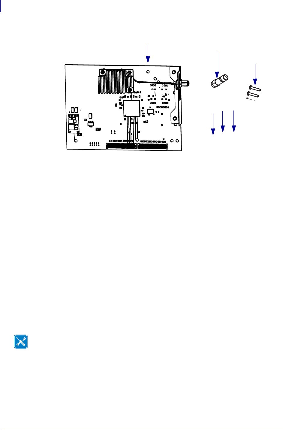
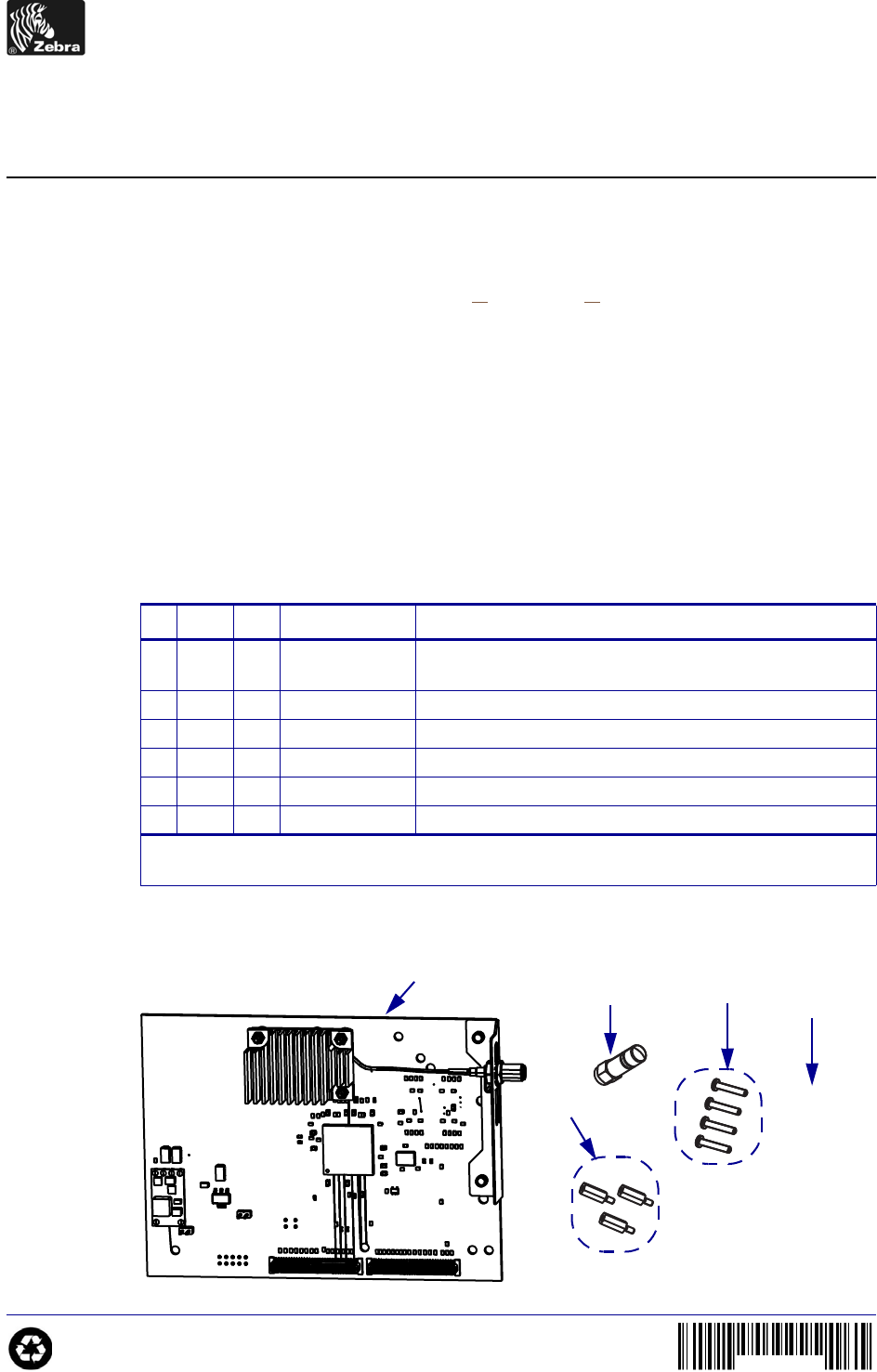
Figure 1 • Kit Contents
Table 1 • Parts List
3Item Qty Part Number Description
Ref 1MInternal Wireless Plus Print Server Option Maintenance
Kit
1129652-006 Internal Wireless Plus PC Board
2139538 Antenna
3379293 Studded Standoff
44 Screw, M3
51Bracket
Bold = Part available for purchase.
Italic = Part not available for purchase; listed and shown for reference only.
1
2 3
4
5

ZebraNet Internal Wireless Plus Print Server for ZM400/ZM600
Prepare for Installation
2
14552L-001 A 2/14/08
Reference Materials
The following manuals and CDs may be helpful references while performing this procedure.
•ZebraNet
® Wireless User Guide
•ZM400/ZM600 User CD
• ZM400/ZM600 Maintenance Manual CD
Tools Required
Tools • You need these tools to complete this procedure:
Phillips Screwdriver Set
Flat-blade Screwdriver Set
Antistatic Wriststrap and Mat
3
ZebraNet Internal Wireless Plus Print Server for ZM400/ZM600
Remove the Electronics Cover
2/14/08 14552L-001 A
Remove the Electronics Cover
1.
2.
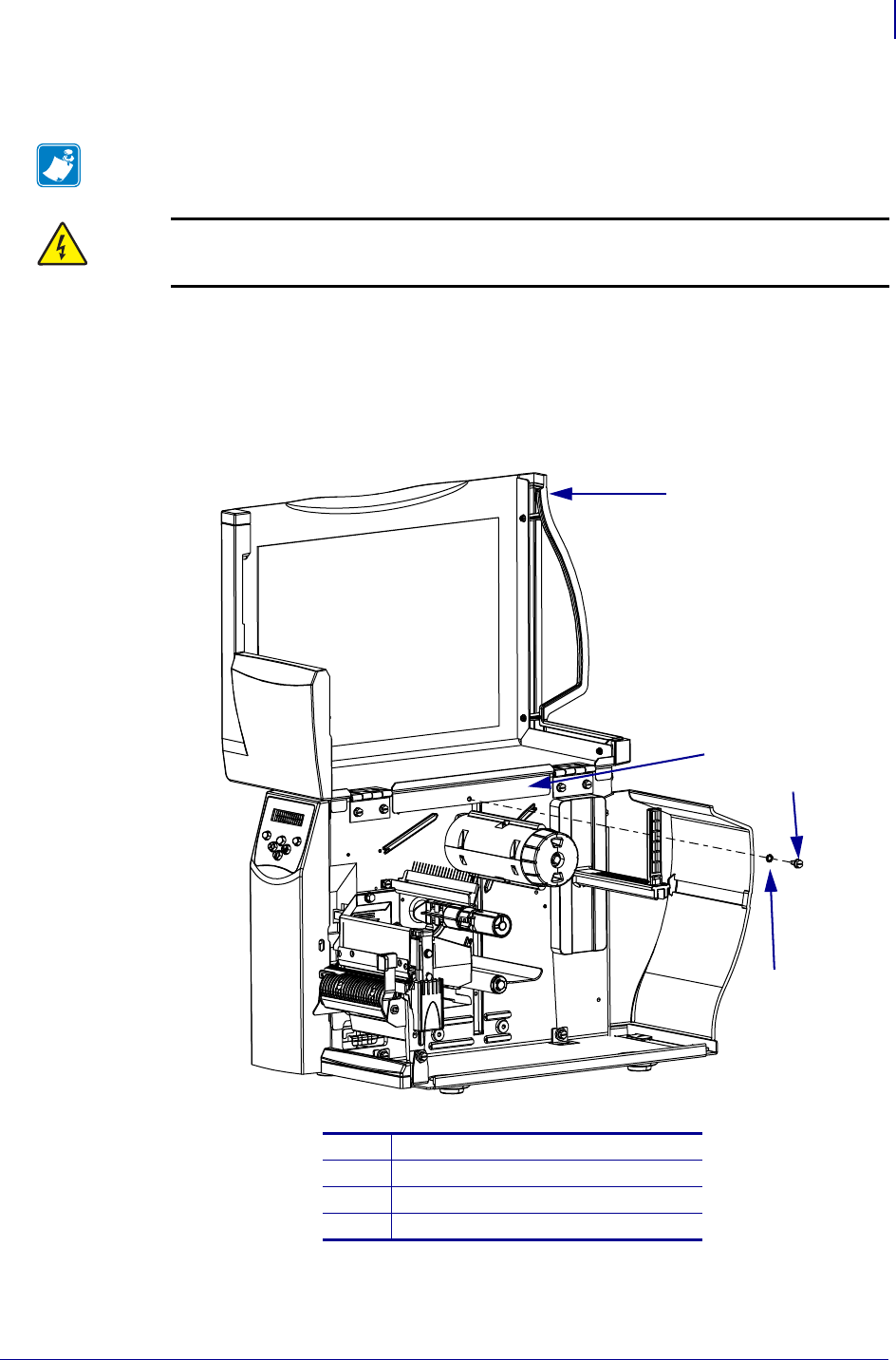
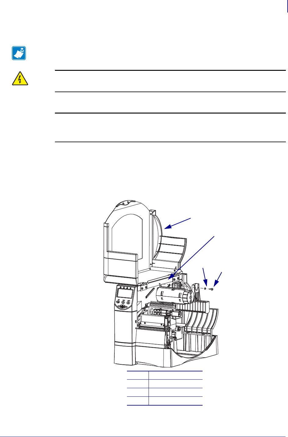
3. See Figure 2. Remove the screw and washer securing the electronics cover.
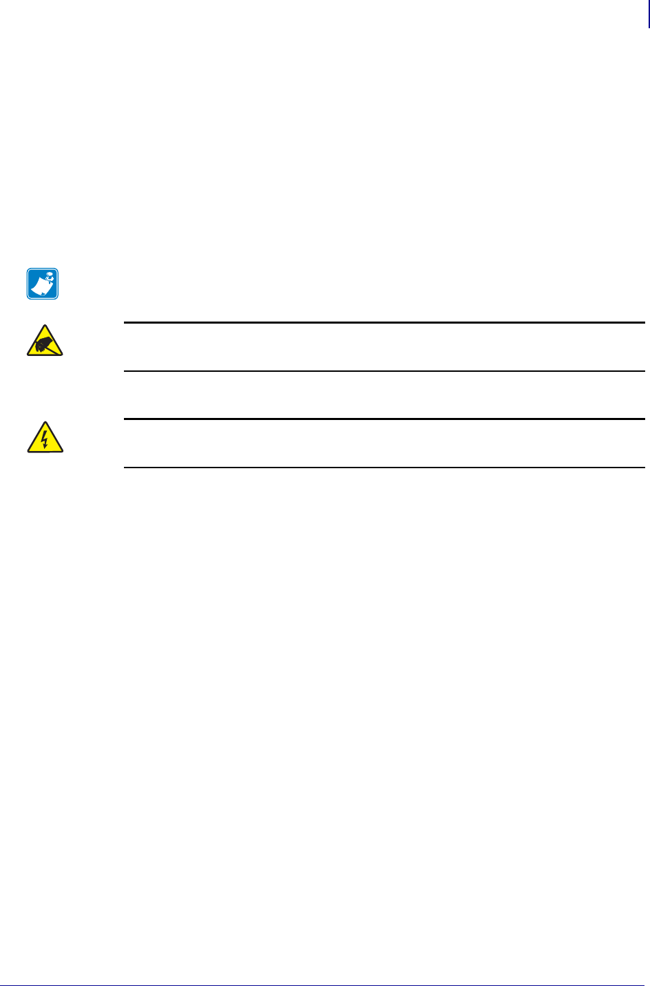
Figure 2 • Locate the Electronics Cover Mounting Screw
4. Close the media door.
Note • Retain all parts removed during disassembly, unless otherwise directed.
Caution • Turn off (O) the printer and disconnect it from the power source before
performing the following procedure.
Turn off (O) the printer and disconnect the AC power cord and all data cables.
Caution • While performing any tasks near an open printhead, remove all rings,
watches, hanging necklaces, identification badges, or other metallic objects that could
touch the printhead.
Remove the media and ribbon.
1Media door
2Electronics cover
3Washer
4Mounting screw
1
2
34
ZebraNet Internal Wireless Plus Print Server for ZM400/ZM600
Remove the Electronics Cover
4
14552L-001 A 2/14/08
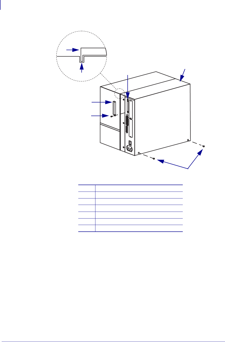
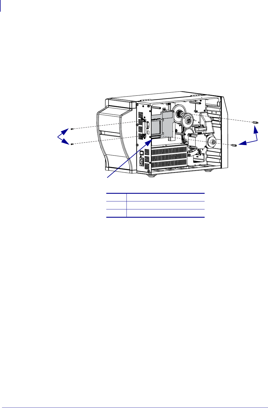
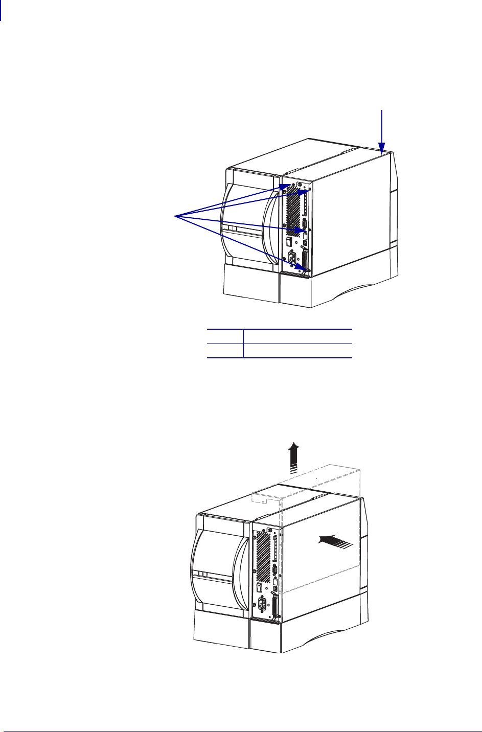
5. See Figure 3. Remove the four mounting screws on the rear of the printer.
Figure 3 • Remove the Electronics Cover Mounting Screws
6. See Figure 4. Remove the electronics cover by pressing in on the electronics cover with
the palm of your hand, and then lifting up on the cover.
Figure 4 • Remove the Electronics Cover
1Electronics cover
2Mounting screws (4)
2
1
2
1
5
ZebraNet Internal Wireless Plus Print Server for ZM400/ZM600
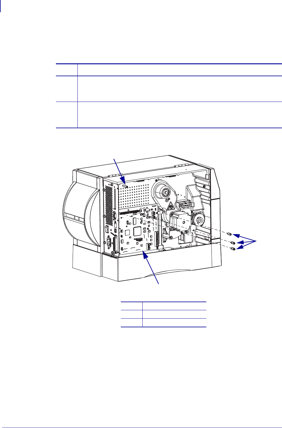
Remove the Old Wireless Plus Print Server Board
2/14/08 14552L-001 A
7. Is there a ZebraNet 10/100 Internal PrintServer or Wireless Plus Print Server already
installed on the printer?
Remove the Old Wireless Plus Print Server Board
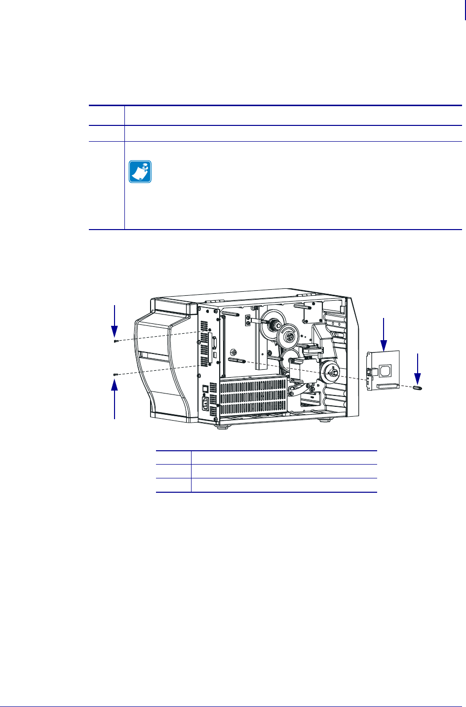
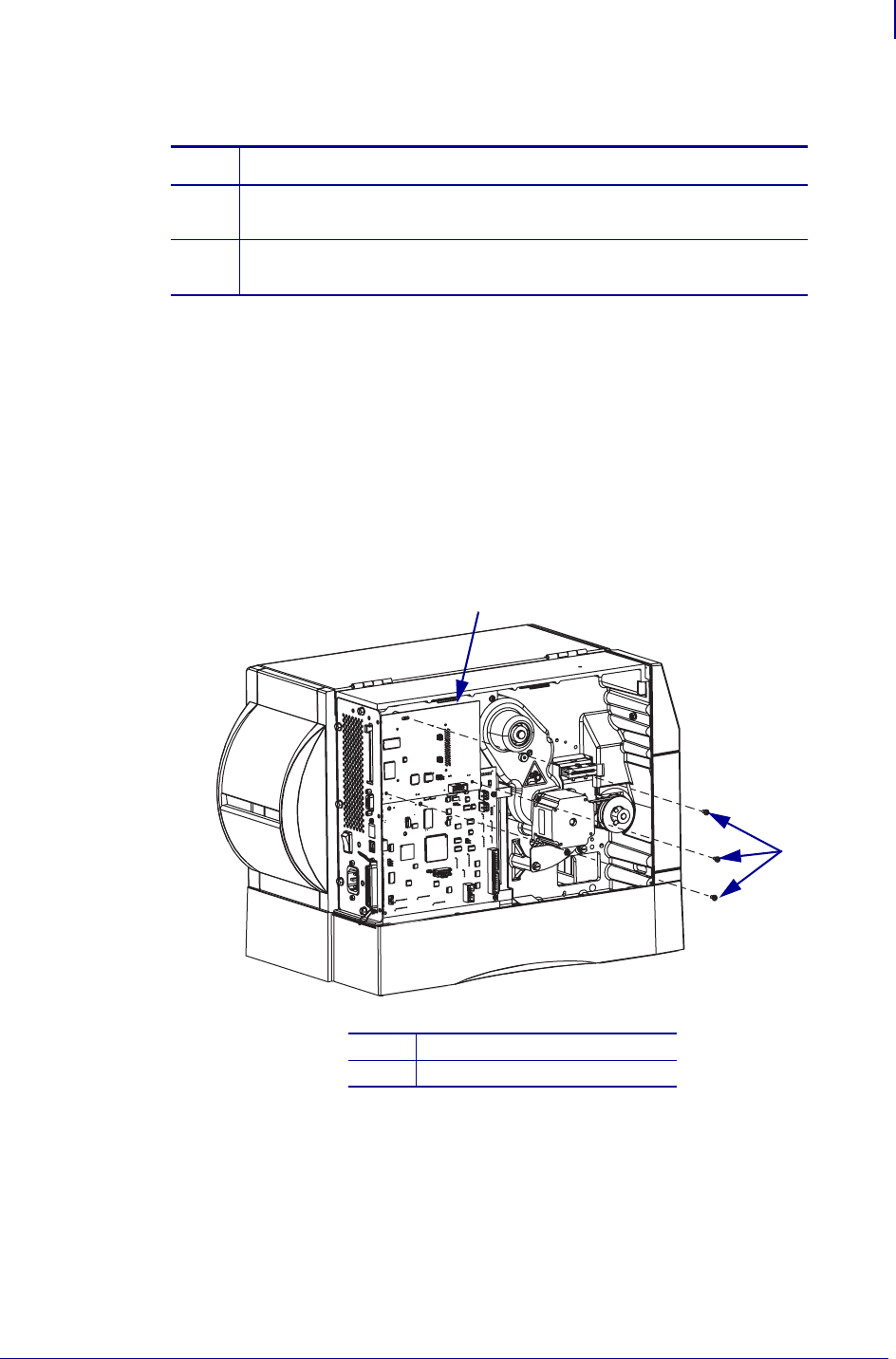
1. See Figure 5. Depending on your wireless plus print server, your printer may have either
two or three mounting screws. Remove the mounting screws from the Wireless Plus Print
Server board.
2. Remove the Wireless Plus Print Server board from the printer.
Figure 5 • Remove the Wireless Plus Print Server Board
3. Go to Install the New Internal Wireless Plus Print Server Board on page 6.
If… Then…
No Go to Install the New Internal Wireless Plus Print Server Board
on page 6.
Yes Continue with Remove the Old Wireless Plus Print Server Board
on page 5.
1Wireless print server board
2Mounting screws (3)
2
1
2
ZebraNet Internal Wireless Plus Print Server for ZM400/ZM600
Install the New Internal Wireless Plus Print Server Board
6
14552L-001 A 2/14/08
Install the New Internal Wireless Plus Print Server
Board
1. Are you installing the Internal Wireless Plus Print Server for the first time?
Figure 6 • Install the Standoffs
2. Insert the upper edge of the internal wireless plus board into the electronics area and in
front of the main logic board.
3. Place the RF connector through the option board slot in the back of the printer.
4. Align the connectors along the bottom edge of the internal wireless plus board with the
connectors on the main logic board.
If… Then…
No a. See Figure 6. Install one standoff in between the two beige connectors on
the main logic board as shown.
b. Go to step 2.
Yes a. See Figure 6. Install the three studded standoffs on the main logic board as
shown.
b. Continue with step 2.
1Cast boss
2Studded standoffs (3)
3Main logic board
3
1
2

7
ZebraNet Internal Wireless Plus Print Server for ZM400/ZM600
Install the Bracket and External Antenna
2/14/08 14552L-001 A
5. While supporting the back of the internal wireless plus board with your fingers, press the
board into place.
6. Install the internal wireless plus board by inserting the four mounting screws into the
standoffs.
Install the Bracket and External Antenna
1. Insert the bottom edge of the bracket in the small slot below the option board opening.
2. Fasten the top of the bracket into place using one of the screws provided in the kit.
3. From the back of the printer, place a washer and a nut on the RF connector.
4. To install the external antenna, screw the antenna on to the RF connector extending out
from the back plate of the printer.
Resume Operations
1. See Figure 3 on page 4. Install the cover by aligning it and sliding down, ensuring the
lower tabs are inside the base and the upper flanges are between the main frame and the
media door.
2. Install the four mounting screws on the back of the printer.
3. See Figure 2 on page 3. Open the media door and install the mounting screw and washer
to secure the electronics cover.
Install the Electronics Cover
1. Reinstall the media and ribbon.
2. Reconnect AC power cord and data cables.
3. Turn on (l) the printer.
After You Complete the Installation
After you have completed this installation, you must download firmware version V53.16.x (or
later) a second time from: www.zebra.com/firmware.
ZebraNet Internal Wireless Plus Print Server for ZM400/ZM600
After You Complete the Installation
8
14552L-001 A 2/14/08
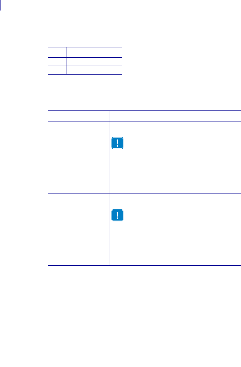
Attach Labels
1. Did you receive one or more labels in your kit?
2. See Figure 7. Examine the labels included with the kit.
There may be several labels included with your kit.
If… Then…
Yes Continue with step 2.
No Skip to step 4.
If you have labels… Then…
With your printer model
in the lower right-hand
corner
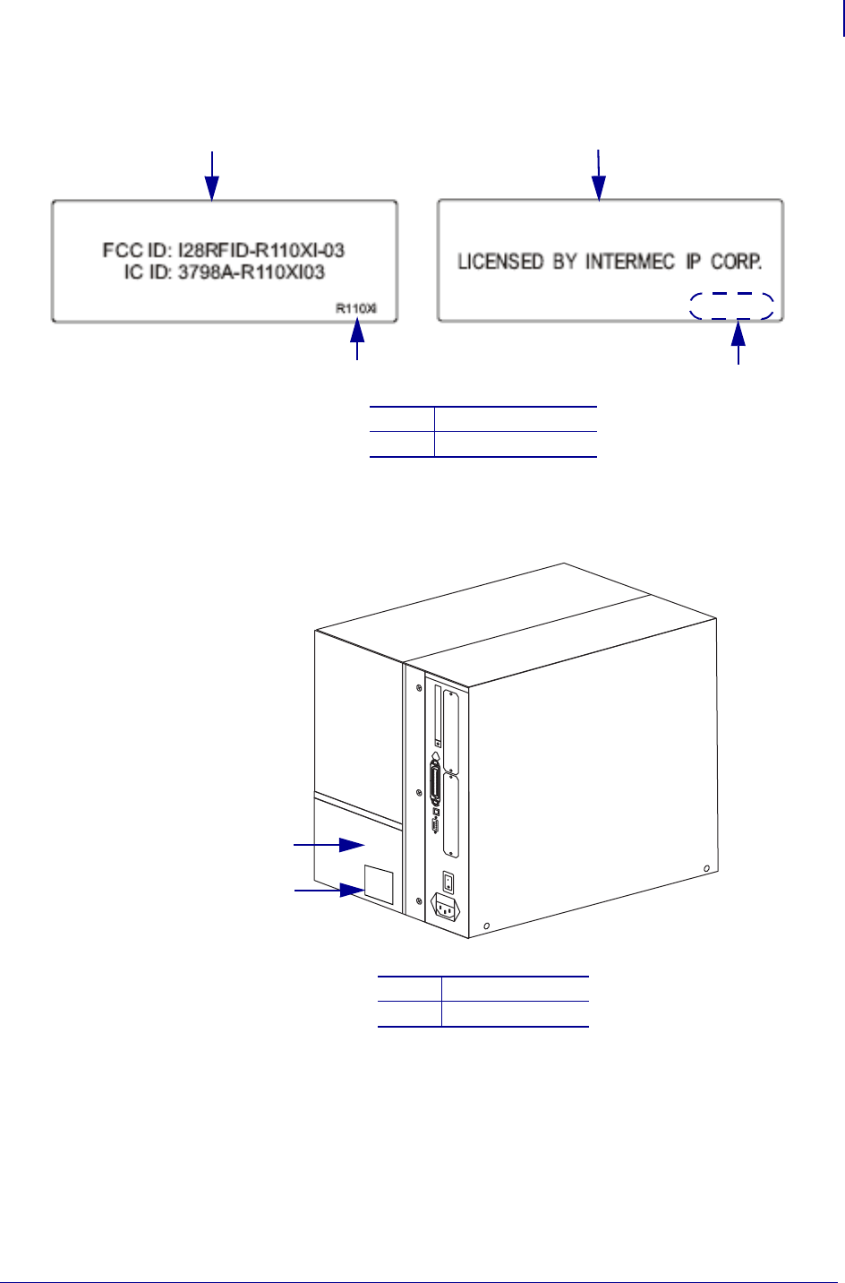
a. See Figure 8. Remove all of the old small plastic labels
affixed to the outside of your printer.
Important • Do not remove the electrical ratings
label, also known as the model plate. The model
plate contains essential user information.
b. See Figure 7. Remove the backing for all of the labels
for your specific printer.
c. See Figure 8. Affix the new printer labels in the area
near the model plate.
d. Continue with step 3.
Blank in the lower right-
hand corner a. See Figure 8. Remove all of the old small plastic labels
affixed to the outside of your printer.
Important • Do not remove the electrical ratings
label, also known as the model plate. The model
plate contains essential user information.
b. See Figure 7. For all labels that are blank in the corner,
remove the backing for these labels.
c. See Figure 8. Affix the new printer labels in the area
near the model plate.
d. Continue with step 3.
9
ZebraNet Internal Wireless Plus Print Server for ZM400/ZM600
After You Complete the Installation
2/14/08 14552L-001 A
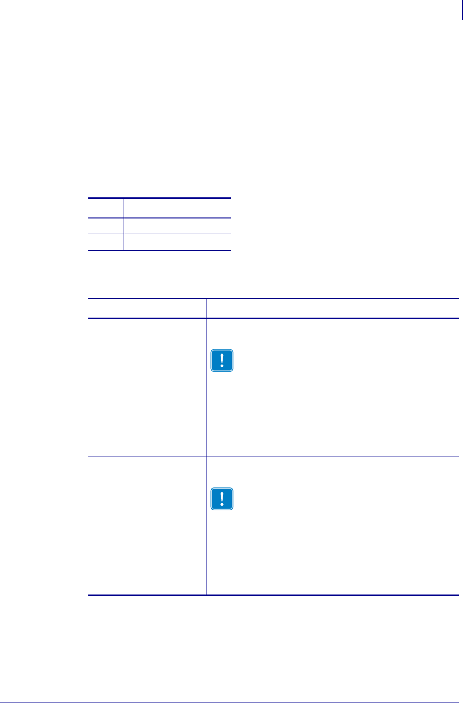
Figure 7 • Sample Labels
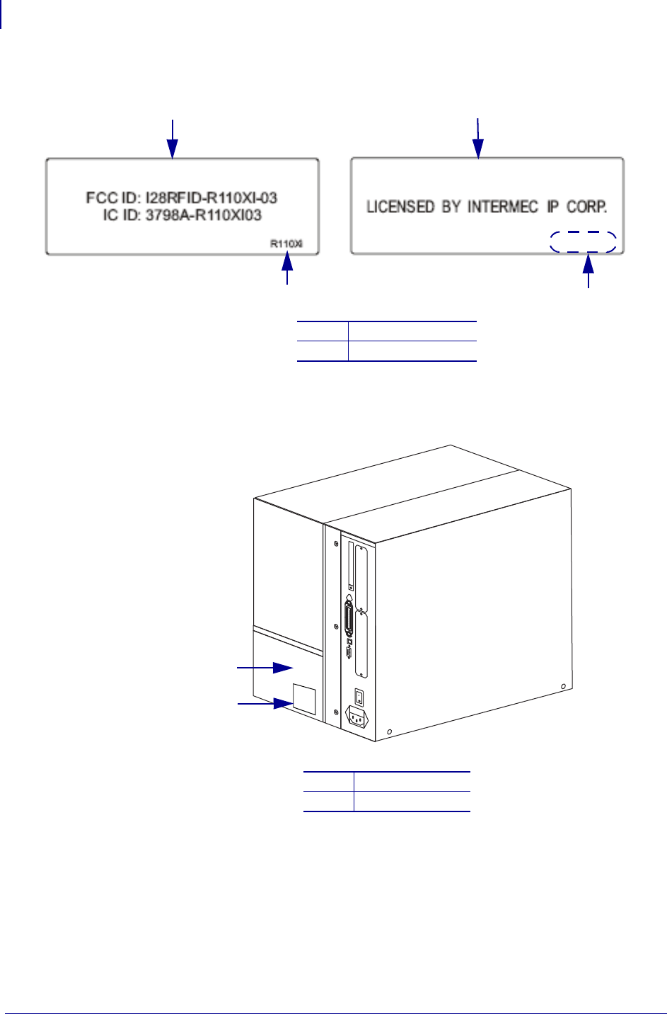
Figure 8 • Label Location
(Need ZM400 graphic)
3. Discard any additional labels included in the kit.
4. The installation is complete.
With Printer Model
2
1
Without Printer Model
1Printer model
2No printer model
1Affix labels here
2Model plate
1
2

Compliance Information
Compliance Information
Compliance Information
FCC Compliance Statement
This device complies with Part 15 rules. Operation is subject to the following two conditions:
1. This device may not cause harmful interference, and
2. This device must accept any interference received, including interference that may cause
undesired operation.
The user is cautioned that any changes or modifications not expressly approved by Zebra
Technologies could void the user’s authority to operate the equipment. To ensure compliance,
this printer must be used with Shielded Communication Cables.
FCC Radiation Exposure Statement
This equipment complies with FCC radiation exposure limits set forth for an uncontrolled
environment. This equipment should be installed and operated with minimum distance 20cm
between the radiator and your body.
This transmitter must not be co-located or operating in conjunction with any other antenna or
transmitter.
Canadian DOC Compliance Statement
This Class B digital apparatus complies with Canadian ICES-003.
Cet appareil numérique de la classe B est conforme à la norme NMB-003 du Canada.