Zida Technologies MB-A815EP-11 Mainboard User Manual Manual A815E1 indd
Zida Technologies Ltd. Mainboard Manual A815E1 indd
UserManual.wiki
>
Zida Technologies
>
MB-A815EP-11 User Manual
>
users manual 3
Contents
1.
users manual 1
2.
users manual 2
3.
users manual 3
4.
users manual 4
5.
users manual 5
6.
users manual 6
7.
users manual 7
users manual 3
Navigation menu
Upload a User Manual
Namespaces
Wiki Guide
HTML
PDF
Info
Views
User Manual
Discussion / Help
Navigation
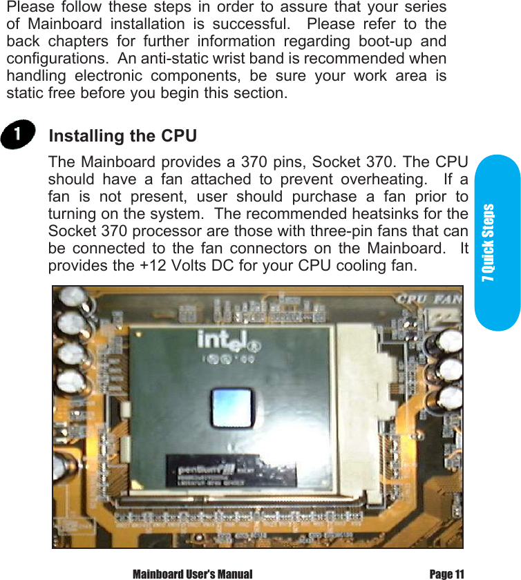
![Jumper settings Set the Jumper JP1 default setting is [1-2], to (2-3) to clear CMOS. JP4 default setting is [1-2] to Panel speaker out, to (2-3) to mix out AC97 codec . JP6 default setting is OPEN, to Enable AC97 CODEC, to CLOSE to Disable AC97 CODEC. JP7 default setting is OPEN, to Enable MC97 CODEC, to CLOSE to Disable MC97 CODEC.Page 10 90-A815E1-A2-00](https://usermanual.wiki/Zida-Technologies/MB-A815EP-11.users-manual-3/User-Guide-165860-Page-1.png)