Zinwave 302-1107 Distributed Antenna System Remote Unit User Manual Job Description
Zinwave Ltd Distributed Antenna System Remote Unit Job Description
Zinwave >
Contents
User manual 1

UNItivity – Installation Manual
January 2016
V1.1 Page 1 of 55 January 2016
Zinwave’s Unified Connectivity Platform
Installation Manual
Copyright Zinwave Ltd. 2016
The information contained herein is the copyright of Zinwave Ltd and is issued on
condition that it is not copied, reproduced or disclosed to a third party, either
wholly or in part, without the consent in writing of Zinwave Ltd.

UNItivity – Installation Manual
January 2016
V1.1 Page 2 of 55 January 2016
Edition
Issue UNItivity-Installation Manual_v1.1 Jan 2016
Warranty
The material contained in this document is provided “as is,” and is subject to being
changed, without notice, in future editions. Further, to the maximum extent
permitted by applicable law, Zinwave disclaims all warranties, either express or
implied, with regard to this manual and any information contained herein,
including but not limited to the implied warranties of merchantability and fitness
for a particular purpose. Zinwave shall not be liable for errors or for incidental or
consequential damages in connection with the furnishing, use, or performance of
this document or of any information contained herein. Should Zinwave and the
user have a separate written agreement with warranty terms covering the material
in this document that conflict with these terms, the warranty terms in the separate
agreement shall control.
Technology licenses
The hardware and/or software described in this document are furnished under a
license and may be used or copied only in accordance with the terms of such
license.
Trademark acknowledgements
Warning: Pentium® is a registered trademark of Intel Corporation. Adobe® is a
trademark of Adobe Systems Incorporated. Windows XP, Windows 2000, and
Windows 98 are U.S. registered trademarks of Microsoft Corporation. Macintosh is
a trademark of Apple Computer. Linux is a trademark of Linus Torvalds. All other
trademarks are the property of their respective holders.
About this guide
This guide contains hardware installation and software configuration & operating
instructions for the Zinwave UNItivity System.
A WARNING notice denotes a hazard. It calls attention to an
operating procedure, practice, or the like that, if not correctly
performed or adhered to, could result in personal injury or death.
Do not proceed beyond a WARNING notice until the indicated
conditions are fully understood and met.
A CAUTION notice denotes a hazard. It calls attention to an
operating procedure, practice, or the like that, if not correctly
performed or adhered to, could result in damage to the product
or loss of important data. Do not proceed beyond a CAUTION
notice until the indicated conditions are fully understood and met.
UNItivity – Installation Manual
January 2016
V1.1 Page 3 of 55 January 2016
Safety notices
Cautions and warnings
This unit is fitted with a 5A 20x5mm anti-surge ceramic fuse (RC). For
continued protection against risk of fire, replace only with same type
and rating of fuse. Keep all product information for future reference.
High voltages exist inside the product; do not remove the lid or
base: No user serviceable parts inside.
If this product is not used as specified, the protection provided by
the equipment could be impaired. This product must be used in a
normal condition (in which all means for protection is intact) only.
No operator serviceable parts are inside this system. Refer servicing
to an authorized Zinwave Ltd service centre. To prevent electrical
shock, do not remove the covers.
Notes
• Read this User Manual and follow all operating and safety instructions.
• Position the power cord to avoid possible damage; do not overload wall outlets.
• Do not place this product on or near a direct heat source, and avoid placing objects on the terminal.
• Do not operate this device near water or in a wet location.
• Use only a damp cloth for cleaning. Do not use liquid or aerosol cleaners. Disconnect the power
before cleaning.
• Installation of the UNItivity system must be contracted to a suitably trained and competent
professional installer.

UNItivity – Installation Manual
January 2016
V1.1 Page 4 of 55 January 2016
Declaration of Conformity
• Hereby, Zinwave Ltd, declares that this Distributed Antenna System is in compliance with the
essential requirements and other relevant provisions of Directive 1999/5/EC.
• Zinwave Ltd, vakuuttaa tŠten että Distributed Antenna System tyyppinen laite on direktiivin
1999/5/EY oleellisten vaatimusten ja sitä koskevien direktiivin muiden ehtojen mukainen.
• Hierbij verklaart Zinwave Ltd, dat het toestel Distributed Antenna System in overeenstemming is
met de essenti‘le eisen en de andere relevante bepalingen van richtlijn 1999/5/EG
• Bij deze verklaart Zinwave Ltd, dat deze Distributed Antenna System voldoet aan de essenti‘le eisen
en aan de overige relevante bepalingen van Richtlijn 1999/5/EC.
• Par la prŽsente, Zinwave Ltd, dŽclare que ce Distributed Antenna System est conforme aux
exigences essentielles et aux autres dispositions de la directive 1999/5/CE qui lui sont applicables
• HŠrmed intygar Zinwave Ltd, att denna Distributed Antenna System stŒr I šverensstŠmmelse med
de vŠsentliga egenskapskrav och švriga relevanta bestŠmmelser som framgŒr av direktiv
1999/5/EG.
• Undertegnede Zinwave Ltd, erklærer herved, at følgende udstyr Distributed Antenna System
overholder de væsentlige krav og øvrige relevante krav i direktiv 1999/5/EF
• Hiermit erklŠrt Zinwave Ltd., dass sich dieser Distributed Antenna System in †bereinstimmung mit
den grundlegenden Anforderungen und den anderen relevanten Vorschriften der Richtlinie
1999/5/EG befindet
• ΜΕ ΤΗΝ ΠΑΡΟΥΣΑ Zinwave Ltd, ΔΗΛΩΝΕΙ ΟΤΙ Distributed Antenna System ΣΥΜΜΟΡΦΩΝΕΤΑΙ ΠΡΟΣ
ΤΙΣ ΟΥΣΙΩΔΕΙΣ ΑΠΑΙΤΗΣΕΙΣ ΚΑΙ ΤΙΣ ΛΟΙΠΕΣ ΣΧΕΤΙΚΕΣ ΔΙΑΤΑΞΕΙΣ ΤΗΣ ΟΔΗΓΙΑΣ 1999/5/ΕΚ
• Con la presente Zinwave Ltd, dichiara che questo Distributed Antenna System è conforme ai
requisiti essenziali ed alle altre disposizioni pertinenti stabilite dalla direttiva 1999/5/CE.
• Por medio de la presente Zinwave Ltd, declara que el Distributed Antenna System cumple con los
requisitos esenciales y cualesquiera otras disposiciones aplicables o exigibles de la Directiva
1999/5/CE
• Zinwave Ltd, declara que este Distributed Antenna System está conforme com os requisitos
essenciais e outras disposi›es da Directiva 1999/5/CE.

UNItivity – Installation Manual
January 2016
V1.1 Page 5 of 55 January 2016
Optical UNIremote interference
This is a “Class A” product (as defined in EN 55022). In a
domestic environment this product may cause radio
interference, in which case the user may be required to take
adequate measures.
FCC compliance and interference statements
UNIhub. This device complies with Part 15 of the FCC rules. Operation is subject to the following two
conditions:
1) This device must accept any interference and
2) This device must accept any interference received including interference that may cause
undesired operation
Changes or modifications not expressly approved by Zinwave Ltd. could void the user’s authority to operate
the equipment.
UNIremote.
This device complies with Part 22, Part 24, Part 27, Part 74 and Part 90 of the FCC rules. Changes or
modifications not expressly approved by Zinwave Ltd. could void the user’s authority to operate the
equipment. For a list of services, please contact Zinwave.
UNIremote with FCC ID: UPO302-0007 only supports services in the following bands of operation:
• 150.0 – 174.0 MHz
• 406.1 – 454.0 MHz
• 456.0 – 512.0 MHz
• 470.0 – 608.0 MHz
• 614.0 – 698.0 MHz
• 698.0 – 824.0 MHz
• 851.0 – 869.0 MHz
• 869.0 – 894.0 MHz
• 928.0 – 929.0 MHz
• 931.0 – 935.0 MHz
• 935.0 – 940.0 MHz
• 1930.0 – 1990.0 MHz
• 2110.0 – 2155.0 MHz
IC compliance statement
The nominal passband gain is 25 dB and the nominal bandwidth is 150 MHz to 2.94 GHz.
The rated mean output power is 20 dBm and the input and output impedances are 50 ohms
The Manufacturer's rated output power of this equipment is for single carrier operation. For situations
when multiple carrier signals are present, the rating would have to be reduced by 3.5 dB, especially where
the output signal is re-radiated and can cause interference to adjacent band users. This power reduction is
to be by means of input power or gain reduction and not by an attenuator at the output of the device."

UNItivity – Installation Manual
January 2016
V1.1 Page 6 of 55 January 2016
Rack mount instructions
Double Pole / Neutral Fusing.
• Elevated Operating Ambient – If installed in a closed or multi-unit rack assembly, the operating
ambient temperature of the rack environment may be greater than room ambient. Therefore,
consideration should be given to installing the equipment in an environment compatible with the
maximum ambient temperature (Tma) specified by the manufacturers. UNIhub has a Tma of 45°C.
• Reduced Air Flow – Installation of the equipment in a rack should be such that the amount of air
flow required for safe operation of the equipment is not compromised.
• Mechanical Loading – Mounting of the equipment in the rack should be such that a hazardous
condition is not achieved due to uneven mechanical loading.
• Circuit Overloading – Consideration should be given to the connection of the equipment to the
supply circuit and the effect that overloading of the circuits might have on overcurrent protection
and supply wiring. Appropriate consideration of equipment nameplate ratings should be used when
addressing this concern.
• Reliable Earthing – Reliable earthing of rack-mounted equipment should be maintained. Particular
attention should be given to supply connections other than direct connections to the branch circuit
(e.g. use of power strips).
• Disconnect Device – The socket outlet shall be installed near the equipment, be easily accessible
and will act as the main point of disconnect for the UNIhub.
• Keep these Instructions in a safe place.
Manual Handling – The UNIhub is heavy and care should be taken to
avoid inquiry when lifting and handling this equipment. To avoid damage
to the equipment do not support the whole weight of the UNIhub using
only 1 handle.
UNItivity – Installation Manual
January 2016
V1.1 Page 7 of 55 January 2016
General safety considerations
The installation of electrical supplies in support of UNItivity products shall be in accordance with national
and local regulations.
Other aspects of the installation for UNItivity products and interconnecting cabling shall be in accordance
with the following standards:
• EN 50174 series: Information technology – Cabling installation
• IEC 60825-2: Safety of laser products – Part 2: Safety of optical fiber communication systems (OFCS)
• This equipment complies with 21CFR1040 - Performance Standards For Light-Emitting Products
(FDA).
RF exposure
This equipment complies with FCC radiation exposure limits set
forth for an occupational/ controlled environment. This
equipment should be operated with a minimum distance of
20cm between radiator and your body.
Optical Safety Precautions
• Do not remove the fiber Port dust covers unless the port is in use. Do not stare directly into a fiber
Port.
• Cover any unconnected fiber ends with an approved cap.
• Do not stare with unprotected eyes at any broken ends of the fiber.
• Use only approved methods for cleaning optical fiber connectors.
• Do not make any unauthorized modifications to this fiber optical system.
• No warning signs are required as it is a Class 1 hazard.
• Use Class 1 test equipment.
Use of controls or adjustments or performance of procedures
other than those specified herein may result in hazardous
radiation exposure.
UNItivity – Installation Manual
January 2016
V1.1 Page 8 of 55 January 2016
Installation, use and storage
UNItivity is designed to operate in conditions conformant with Pollution Degree 2 as defined in IEC 60950
(the normal environmental class for offices).
The installation of sub-assemblies into the main units of UNItivity shall only be undertaken if precautions
required by IEC/TS 61340-5-1 have been taken.
This covers the installation of Zinwave Optical Modules into the UNIhub Unit.
CLASS I PLUGGABLE EQUIPMENT TYPE A as defined in IEC 60950. This
equipment is intended for connection to other equipment or a
network, relies on connection to protective earth and must be
connected to an earthed mains socket-outlet.
Country specific warnings:
Finland "Laite on liitettŠvä suojamaadoituskoskettimilla varustettuun
pistorasiaan"
Norway “Apparatet må tilkoples jordet stikkontakt”
Sweden "Apparaten skall anslutas till jordat uttag
Operating voltage is autosensing 120V or 230V.
Signal and input power
The input power to the UNIhub Unit when configured as a Primary
should not exceed +15dBm. Power levels greater than +25dBm will
damage the unit
The input power to the Zinwave UNIremote should not exceed -
10dBm. Power levels greater than 0dBm will damage the unit
The total broadband composite output power of the UNIremote is
limited to +18 dBm in Europe and +20 dBm in the USA and Canada. The
maximum allowed EIRP in the USA & Canada is +28 dBm which
corresponds to an antenna gain of 8 dBi. Contact Zinwave for the
maximum output power in other regions
The maximum allowed antenna gain when operating in Europe in the
2.4GHz ISM band shall be +2 dBi. Contact Zinwave for further
information regarding use of the ISM band in other regions

UNItivity – Installation Manual
January 2016
V1.1 Page 9 of 55 January 2016
Table of Contents
Safety notices ................................................................................................................................................................ 3
General safety considerations ...................................................................................................................................... 7
1 Overview of UNItivity, Zinwave’s unified connectivity platform ....................................... 11
1.1 Overview ....................................................................................................................................................... 11
1.1 Key features.................................................................................................................................................. 12
2 System architecture.................................................................................................................. 14
2.1 The components ........................................................................................................................................... 14
2.1.1 UNIhub configured as a Primary:....................................................................................................... 14
2.1.2 UNIhub configured as a Secondary: ................................................................................................... 15
2.2 UNIhub Plug in Modules............................................................................................................................. 16
2.2.1 Service Module (SM) ............................................................................................................................ 16
2.2.2 Optical Module (OM) ........................................................................................................................... 16
2.2.3 UNIremote (RU) ................................................................................................................................... 16
2.3 Antenna ........................................................................................................................................................ 16
2.4 Configuration and Control ......................................................................................................................... 16
3 Key Installation specifications summary ............................................................................... 17
4 Hardware Installation.............................................................................................................. 18
4.1 Overview ....................................................................................................................................................... 18
4.1.1 Module types ......................................................................................................................................... 19
4.1.2 Slot numbering...................................................................................................................................... 19
4.2 Installing the UNIhub .................................................................................................................................. 20
4.3 Install the UNIhub into a rack .................................................................................................................... 20
4.3.1 Mounting Kit ......................................................................................................................................... 21
4.4 19 Inch rack mounting ................................................................................................................................ 22
4.5 Open Frame rack mounting ....................................................................................................................... 23
4.6 Provide mains power to UNIhub ................................................................................................................ 24
4.7 UNIhub Front Indicators: ........................................................................................................................... 24
4.7.1 UNIhub front panel LED status .......................................................................................................... 24
4.7.2 Serial Interface wiring diagram .......................................................................................................... 25
4.7.3 Populating the UNIhub ........................................................................................................................ 25
4.7.3.1 Installing a Module (general instructions) ..................................................................................... 26
4.7.3.2 Typical Module LED status ............................................................................................................. 26
4.8 Installing the SH .......................................................................................................................................... 27
4.9 Installing the RU’s ....................................................................................................................................... 27
4.9.1 Mounting a UNIremote ........................................................................................................................ 27
4.9.2 Powering an RU .................................................................................................................................... 28
4.9.2.1 RU 48V, via Rack-mounted Central PSU ...................................................................................... 30
5 Fiber Optic Requirements ....................................................................................................... 32
5.1 Fiber Optic Interface ................................................................................................................................... 33
5.1.1 Zinwave Patch cords ............................................................................................................................ 33
5.1.1.1 Multimode ......................................................................................................................................... 34
5.1.1.2 Single Mode ...................................................................................................................................... 34
5.1.2 Non Zinwave patch cords..................................................................................................................... 34
5.1.2.1 Fiber and Connector Specifications for Zinwave equipment ....................................................... 35
5.2 Use of Single Mode or Multimode Fiber cable .......................................................................................... 36
5.3 Fiber optic Connectors ................................................................................................................................ 37
5.4 Ferrule Types ............................................................................................................................................... 38
5.4.1 APC (Angled Physical Contact) .......................................................................................................... 38
5.4.2 UPC (Ultra-polished Physical Contact) .............................................................................................. 39
5.4.3 PC (Physical Contact) .......................................................................................................................... 39
5.4.4 Effects of Back Reflections on system performance .......................................................................... 39
5.4.4.1 How to diagnose an optical link with an OTDR ............................................................................ 40
5.4.5 Fiber Inspection and Cleaning ............................................................................................................ 41
5.4.5.1 Inspection .......................................................................................................................................... 41

UNItivity – Installation Manual
January 2016
V1.1 Page 10 of 55 January 2016
5.4.5.2 Cleaning Fibers ................................................................................................................................ 42
6 Making the signal connections ................................................................................................ 43
6.1 Connecting UNIhub to the fiber infrastructure ........................................................................................ 44
6.1.1 Connecting UNIhub to an RU ............................................................................................................. 45
6.1.2 Connecting an RU to Antennas ........................................................................................................... 46
6.2 Connecting SM Inputs ................................................................................................................................. 47
7 Antennas ................................................................................................................................... 48
7.1 Installation of two antennas ........................................................................................................................ 48
7.1.1 TX-RX isolation .................................................................................................................................... 48
7.1.2 Uplink/Downlink Balance .................................................................................................................... 50
7.1.3 Isolation Measurement Techniques .................................................................................................... 51
8 UNItivity platform support for MIMO services ................................................................... 52
9 Abbreviations ........................................................................................................................... 54
10 Revision History ....................................................................................................................... 55
UNItivity – Installation Manual
January 2016
V1.1 Page 11 of 55 January 2016
1 Overview of UNItivity, Zinwave’s unified connectivity
platform
1.1 Overview
UNItivity is a unified connectivity platform for in-building wireless and IP data coverage.
Based on advanced photonics and wideband amplifier technology, UNItivity has been designed to
provide Ubiquitous RF coverage over large areas and to support a multitude of wireless and IP data
services, irrespective of carrier frequency or signal protocol.
The wideband design is unique in its offering of inherent support for all radio standards, i.e. systems
carrying a multitude of different services can be implemented without requiring multiple infrastructure
overlays, or specific band units. In addition, new services can be easily added to the distribution system
without needing to add more components to the infrastructure.
Enhanced scalability is achieved through a double-star architecture (UNIhub configured as Primary or
Secondary and up to 64 UNIremote), while also supporting small site solutions in a single star configuration
(with up to 8 UNIremote). The UNItivity platform can thus be used to provide cost-effective coverage in
small, medium and large area installations.
A modular system design adds another dimension of flexibility to UNItivity, allowing use of the same set of
equipment for a wide variety of different installations. All UNIhub use the same chassis with their function
defined by the modules inserted in them. Only those modules required need be inserted, allowing each
installation to “grow on demand”, and therefore be tailored to suit almost every environment and building
topology in the most cost-effective way.
Throughout the document the UNItivity products will be referenced as follows to simplify explanation of
functionality and operation:-
UNIhub – Configured as a Primary Unit – PH
UNIhub – Configured as a Secondary – SH
UNIremote – RU
Optical Module – OM
Service Module - SM

UNItivity – Installation Manual
January 2016
V1.1 Page 12 of 55 January 2016
1.1 Key features
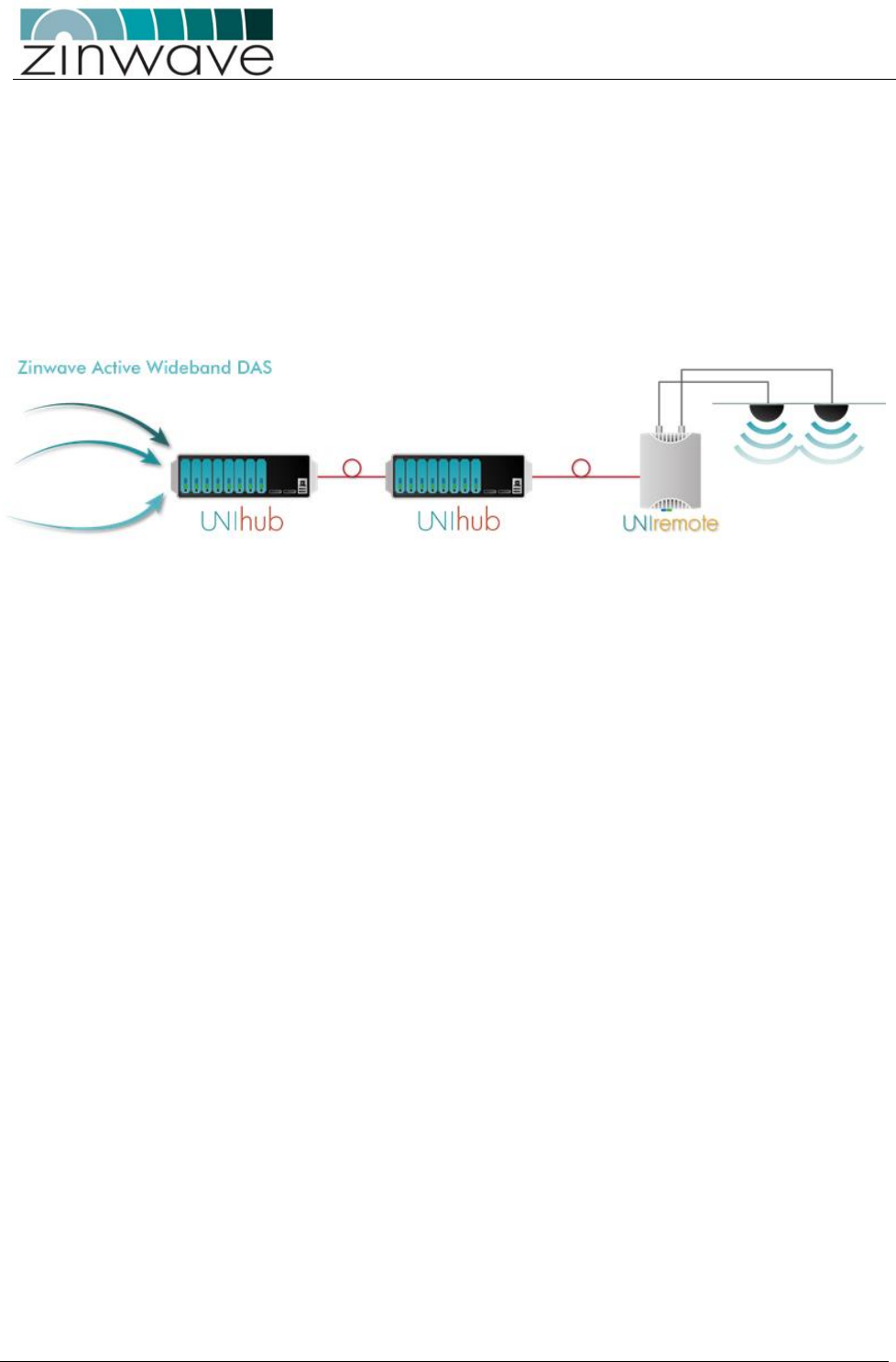
Simple 3-stage fiber-optic DAS: one PH distributes to eight SH, each of which distributes to eight
RU. This gives a maximum of 64 RU fed from one PH (when more RU are required, more than one
PH can be used within a system).
The same components support a 2-stage, single star configuration: one PH distributing to 8 RU.
Wide frequency range: 150 – 2700 MHz, with both FDD and TDD systems supported.
Each UNIhub has four inputs. All four are used as service inputs in the PH. In the SH, one input is
used for an OM which will form the connection to the PH.
Only system to deliver truly broadband solution over multimode fiber (MMF), but can also be used
over single mode fiber (SMF).
Maximum total supported cable distances: The maximum fiber loss per link is 5dBo. This corresponds to
the following typical lengths:
550m for MMF with modal bandwidth of at least 500MHz.km @ 1300 nm
2000m for SMF. Greater distances may be possible following an accurate measurement of the
optical loss
Self-calibrating system with gain levels adjusted automatically to accommodate different cable
lengths
Hot-pluggable modules used in both PH and SH
Web based network management with SNMP monitoring
Unique service distribution matrix on the UNIhub.

UNItivity – Installation Manual
January 2016
V1.1 Page 13 of 55 January 2016
Zinwave’s patented technology allows the multimode or single mode optical fibers specified for structured
(or generic) cabling by the following standards to be used as the transmission system:
North America: ANSI/TIA/EIA-568 series;
European: EN 50173 series;
International: ISO/IEC 11801.
NOTE: Optimal performance of UNItivity may require the re-termination of the optical fibers within legacy
multimode optical fiber infrastructures installed using components meeting the above-mentioned
standards.
The Zinwave transceivers within the UNIhub and antenna units are “fiber agnostic” i.e. they can be used
with either 50/125 mm or 62.5/125 mm MMF, or with SMF. UNItivity channels can be up to 550 metres
long provided that the MMF cable has a modal bandwidth of at least 500MHz/km @ 1300 nm.
NOTE: Channel lengths of up to 2000 metres can be delivered, using the same UNItivity System
components, over SMF cabling.
This length of interconnection is more than adequate to facilitate a high quality, broadband, in-building
coverage extension system for multiple, simultaneous wireless feeds. Without Zinwave’s technology, such
distances can only be achieved in most scenarios by expensive re-cabling of buildings using coaxial cables or
single mode optical fiber, or by reverting to narrowband techniques which restrict the systems’ capability.
Zinwave’s unified connectivity platform is ideally suited to applications where multiple cellular and/or
WLAN services are required and can be easily configured for various deployment scenarios such as: at
campuses, large high-rise buildings and multi-tenanted facilities.
UNItivity – Installation Manual
January 2016
V1.1 Page 14 of 55 January 2016
2 System architecture
The UNItivity platform is built up of UNIhub, PH or SH units and RU’s. Smaller systems comprise a single PH
and up to 8 RU’s. Larger systems can comprise one or more PH each of which can serve up to eight SH and
hence up to sixty-four RU’s).
2.1 The components
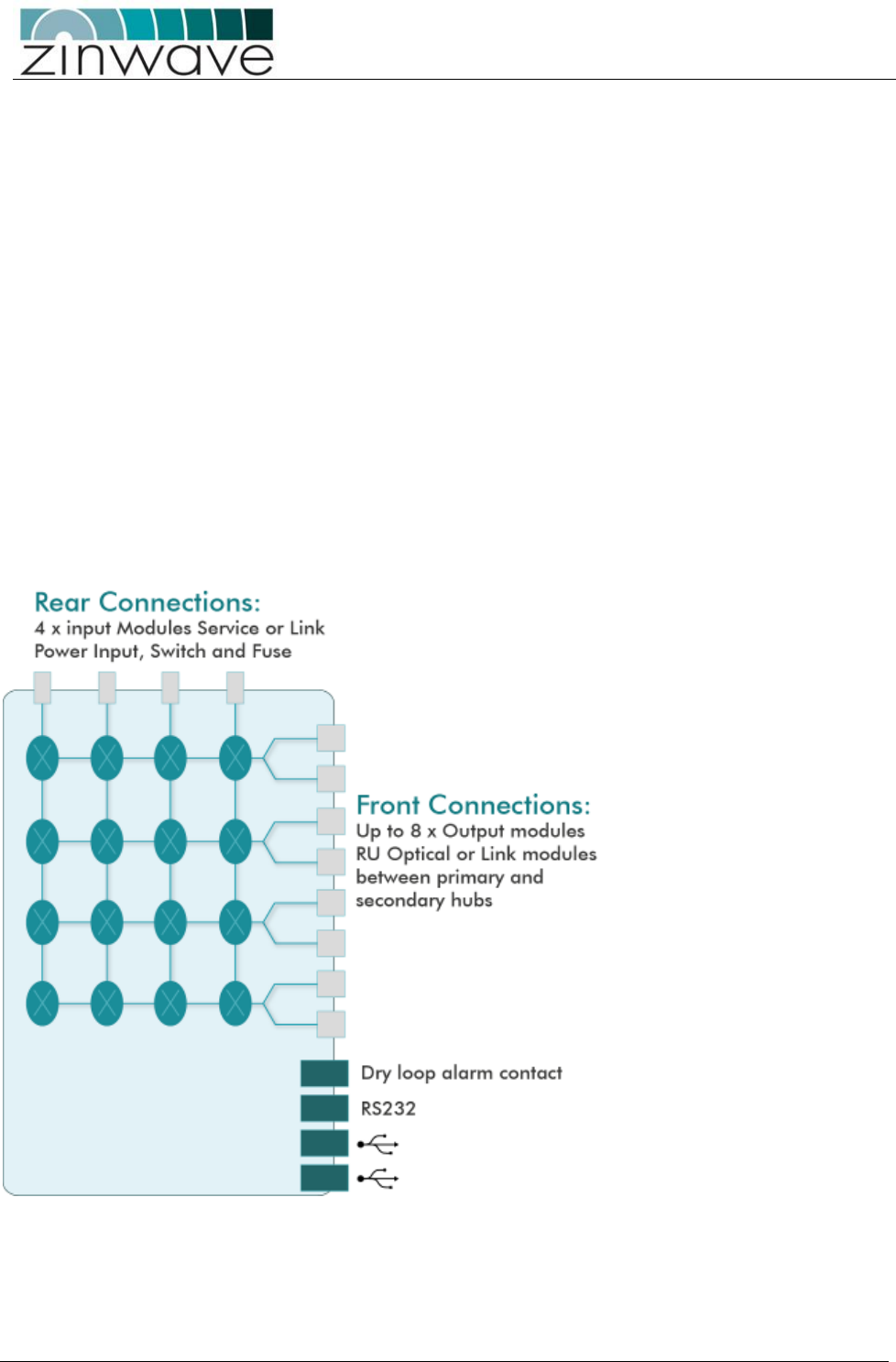
2.1.1 UNIhub configured as a Primary:
The PH interfaces to service sources such as base stations or repeaters via Service modules (SM). It can be
equipped with up to 4 SM in the rear which accept signals from any service in the range of 150-2700 MHz.
It can connect to a SH in a double star configuration, direct to RU in a single star configuration, or a mixture
of both.
Each UNIhub can be equipped with up to 8 Optical modules (OM) in the front to connect via optical fiber to
a SH or RU. Note Only two UNIhub can be daisy chained together.
The PH schematic is shown below:

UNItivity – Installation Manual
January 2016
V1.1 Page 15 of 55 January 2016
2.1.2 UNIhub configured as a Secondary:
SH interfaces to a PH through an OM fitted in the rear and distributes and receives RF signals from
the RU. Up to OM’s can be fitted in the front to connect via optical fiber to 8 RU’s.
The switch matrix within the UNIhub, independent of configuration allows for further control over
distribution of RF signals through the platform.

UNItivity – Installation Manual
January 2016
V1.1 Page 16 of 55 January 2016
2.2 UNIhub Plug in Modules
2.2.1 Service Module (SM)
SM’s, fitted to the rear of the PH, provide connection of the RF signal sources (e.g. BDA,
BTS, and WLAN access point) via a pair of simplex N-type female connectors per RF port.
The ports are labelled A to D for connecting up to four RF transceivers. The ports labelled
“IN” are connected to the transmit port of the RF transceiver (= downlink). The ports
labelled “OUT” are connected to the receive ports of the RF transceivers (= uplink).
2.2.2 Optical Module (OM)
Up to 8 OM’s can be fitted to the PH for connection to SH in a double star configuration
or direct to up to RU for a single star configuration. Up to 8 OM can be fitted to the SH
for connection 8x RU’s, plus 1 (rear) for connection to the PH
The OM have an angled SC connector (APC-SC) in the transmit direction and a straight
SC connector (PC-SC) in the receive direction.
All modules require an appropriate Zinwave patch cord irrespective of the existing or
installed fiber and connector type
2.2.3 UNIremote (RU)
The RU defines the final cell coverage, communicates via optical link to
UNIhub and receives and amplifies signal from user, hand held devices,
laptops, mobiles phones
An RU is a small wall or ceiling mountable units which amplify the
received signals for transmission over a wireless link (in the case of the
downlink signals) and amplify the received wireless signals for
transmission over the optical link (in the case of the uplink signals).
2.3 Antenna
The Zinwave UNItivity Platform can use a variety of antennas connected to the RU via coaxial cable.
The choice of Antenna will depend on the service requirement within the operational bandwidth of
the system.
It is important to ensure that any installed antennas meet the Tx/Rx isolation requirements
detailed in this document, and that they are installed in accordance with all relevant safety and
exposure regulations
2.4 Configuration and Control
The UNItivity platform provides a built-in Element Management System (EMS), for centralised
monitoring, and configuration. With a user friendly web interface, the management features can be

UNItivity – Installation Manual
January 2016
V1.1 Page 17 of 55 January 2016
accessed using a standard Internet browser, and standard alarms management tools, thus not
requiring any proprietary equipment or software.
Configuration and set up of the system is detailed in the “Configuration and Control Guide”.
3 Key Installation specifications summary
Fiber specification
Optical Loss per link
<5dBo
Optical Return Loss
(reflection)
Better than 30dB
Recommended Fiber type
Single mode
Recommended connector type
APC
Antenna isolation
Better than 40 dB between
Tx and Rx antennas
Maximum Distance between
Centralized power supply and RU
At least 200m ( using all
cores/4 pairs of CAT5 cable )
UNItivity – Installation Manual
January 2016
V1.1 Page 18 of 55 January 2016
4 Hardware Installation
This chapter explains how to install a UNIhub, UNIremote and Antennas.
4.1 Overview
Given the wide range of possible configuration with the UNItivity platform this installation manual details
the installation steps required to set up a dual star configuration. Alternative configuration installation will
utilise a subset of these instructions.
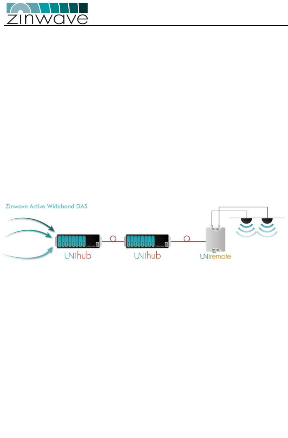
Fig. 21 Simple dual-star configuration to illustrate installation procedures
While all locations are different it is recommended that UNItivity hardware is installed in the following
order:
Install the PH into a 19" rack.
o Provide mains power to PH and switch on.
o Populate the PH with required number of SM,
o Populate the PH with required number of OM.
Install the SH into a 19" rack.
o Provide mains power to PH and switch on.
o Populate the PH with required number of OM.
Install RU’s and Antennas
Make optical and RF connections:
o Connect PH and SH via fiber infrastructure.
o Connect UNIremote to PH and SH.
o Connect Antennas to RU’s
o Apply power to RU’s
Connect service inputs to PH.
Once you have done this, you’re ready to configure your system using the pre-installed software, via a web
browser. This is explained in the “Configuration and Control Guide”.
UNItivity – Installation Manual
January 2016
V1.1 Page 19 of 55 January 2016
4.1.1 Module types
Before installing modules, it may help to understand what each module does, and where it can be installed
(i.e. front or rear panel of a UNIhub):
Table 21 Zinwave UNItivity Module types
Table 21
Module
Description
Installed in?
Connectors
Primary
Secondary
SM
Input of RF signal sources (e.g. BDA,
BTS,)
Rear slots only
N/A
N-type female
OM
Fiber (SM APC, MM PC) link between
UNIhub or RU’s
Front slots only
Rear slots (connection. to PH)
Front slots (connection to RU)
SC duplex
(APC Tx PC Rx)
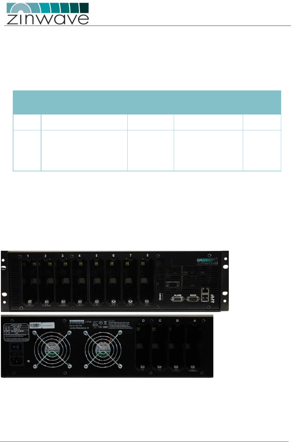
4.1.2 Slot numbering
The slots on the front and rear panels adhere to a numbering system that is reflected in the web-based
configuration application:
Front (from left to right, looking from the front of the unit) slots 1 to 8
Rear (from right to left, looking from the rear of the unit) slots A to D
UNItivity – Installation Manual
January 2016
V1.1 Page 20 of 55 January 2016
4.2 Installing the UNIhub
UNIhub is designed to have front to back air flow and the installation
of the equipment in a rack should be such that the amount of air flow
required for safe operation of the equipment is not compromised.
4.3 Install the UNIhub into a rack
UNIhub are heavy 3U units (14.5kg) which must be supported at
the front when installed into a 19" rack.
Manual Handling – UNIhub is heavy and care should be taken to
avoid inquiry when lifting and handling this equipment. To avoid
damage to the equipment do not support the whole weight of a
UNIhub using only 1 handle.
There are many 19" rack systems on the market of various depths. It is essential that the weight of the
UNIhub is supported at the front. If it is not possible, alternative support mechanisms must be used such as
front-to-rear chassis runners or fully supported shelves.
It is beyond the scope of this manual to cover all rack depths and mounting systems. Here we give an
example installation using the supplied rack-mounting brackets.
UNItivity – Installation Manual
January 2016
V1.1 Page 21 of 55 January 2016
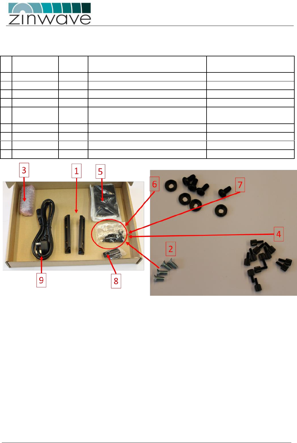
4.3.1 Mounting Kit
Each UNIhub is delivered with an accessory box. This includes the following parts:
Zinwave part
Number
Qty
Part detail
Function
1
142-0231-01
1
PENTAIR INPAC HANDLES (PAIR)
Handles for UNIhub
2
128-0016
4
SCREW M5X12 CSK POZI STL ZINC
Handle screws
3
142-0048-05
12
3000 HUB MODULE BLANK PLATE
Blanking plates for unused slots
4
128-0043
12
SCREW THUMB 6-32X8MM PC CASE
Fixing screws for blanking plates
5
142-0232-01
2
PENTAIR RECESSED ANGLE BRACKET
Mounting brackets for Open
frame racks
6
128-0113
4
M6 CUP WASHER BLACK
Mounting Bracket washers
7
128-0112
4
SCREW M6x12 PAN POZI STL BLACK
Mounting Bracket screws
8
507-0003-02
1
EMS USB
Latest software for UNIhub
9
1
Mains cord for hub ( country specific)
The UNIhub is designed to mount directly into a 19 inch rack framework with no additional mounting
bracketry.
To install the UNIhub into an “open” frame or relay rack the additionally supplied mounting brackets will be
required.
UNItivity – Installation Manual
January 2016
V1.1 Page 22 of 55 January 2016
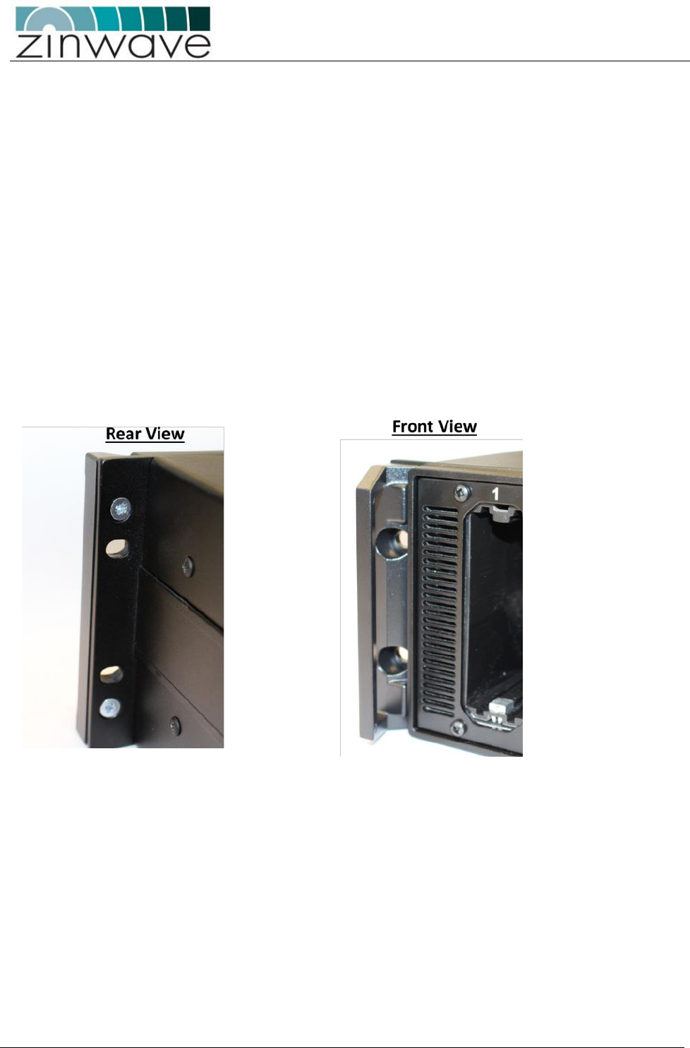
4.4 19 Inch rack mounting
For mounting directly into a 19 inch rack the brackets (5) and associated washers (6) and screws (7) will not
be required
To mount into a 19 inch rack in addition to the kit of parts detailed you will need the following tools and
equipment before you start:
4 x M6 cage nuts appropriate for 19 inch rack frame
M6 pozi-drive screwdriver
Flat-bladed screwdriver
Cage nut insertion/extraction tool
Fix the Handles(1) to the UNIhub using screws (2)
.
Install the cage nuts into the rack using a cage nut insertion/extraction tool.
Fit the UNIhub into the rack using the pan head screws (7) and nylon washers (6).
UNItivity – Installation Manual
January 2016
V1.1 Page 23 of 55 January 2016
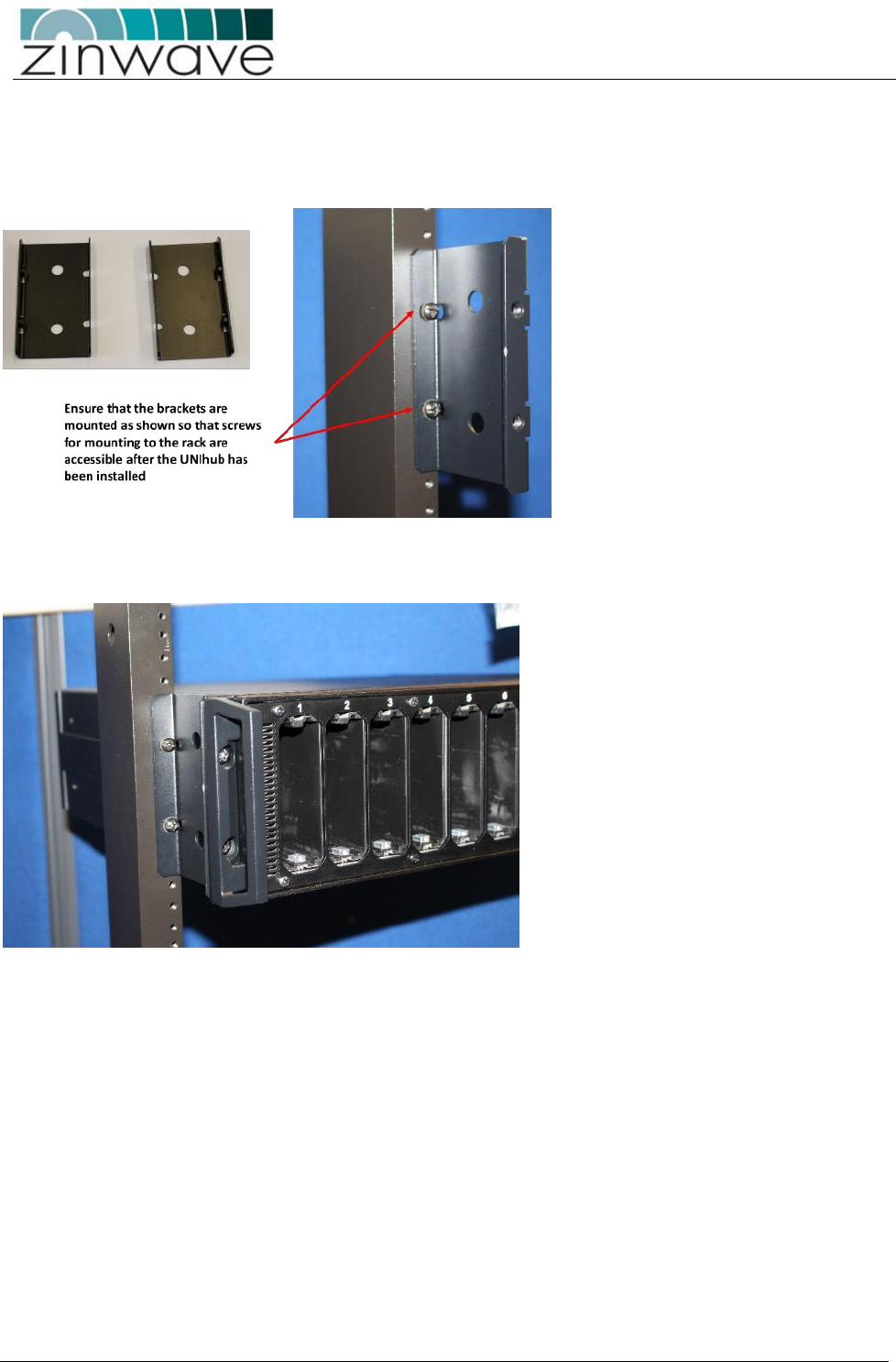
4.5 Open Frame rack mounting
Fit the brackets(5) and associated washers(6) and screws(7) to the frame in the required position using
appropriate fixing for the rack ( not supplied)
Mount the UNIhub onto the offset bracket using the using the pan head screws (7) and nylon washers
(6).
UNItivity – Installation Manual
January 2016
V1.1 Page 24 of 55 January 2016
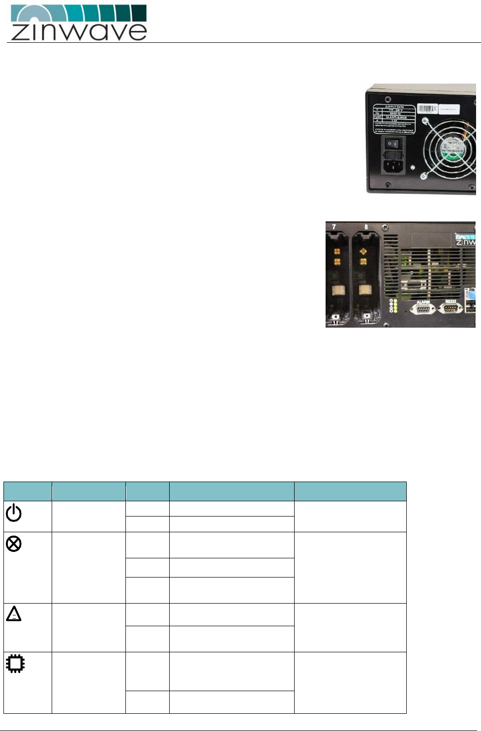
4.6 Provide mains power to UNIhub
Make sure that the ON/OFF switch is in the OFF (O) position.
Connect the AC power cord using the supplied IEC mains cord. Note the UNIhub
has universal supply and voltage selection is not required.
Plug the AC power cord into an outlet providing AC power
Switch on the UNIhub.
Check the LED status indicators shows correct operation.
Note if powered up with no modules installed the UNIhub should show
4 green LEDs. If modules are installed then the alarm warning and fault
LEDs may show alarm conditions at initial start-up. This is due to the
fact that no UNIremote elements are connected. These alarms can be
cleared via the UNIhub Set Up page of the Configuration process once
the system is correctly configured. Refer to the configuration Guide for
more information.
Note: The UNItivity platform is designed to allow modules to be hot swapped. However during initial
installation where modules may plugged in and out more frequently than under normal operating
conditions it is recommended that the power to UNIhub is switched off until the initial module installation
is completed
4.7 UNIhub Front Indicators:
The front of each UNIhub is equipped with a number of LEDs and interface options
4.7.1 UNIhub front panel LED status
LED
Status
Description
Notes
Power Indication
Green
Power connected to CPU board
Shows processor is correctly
powered
Off
No power connected
Service Indications
Green
No error. System is fully
functional
This alarm cannot be masked
and will ALWAYS be Red
when loss of service
conditions active.
Red
Loss Of service currently active
Red/Green
Flashing
Firmware programming in
progress
Warning Indication
Green
All Units operating correctly
Orange
Service or Hardware warning
currently active
CPU Indicator
Green
CPU running
Shows Processor is correctly
operational (same as current
functionality)
Red
CPU restarting
!
UNItivity – Installation Manual
January 2016
V1.1 Page 25 of 55 January 2016
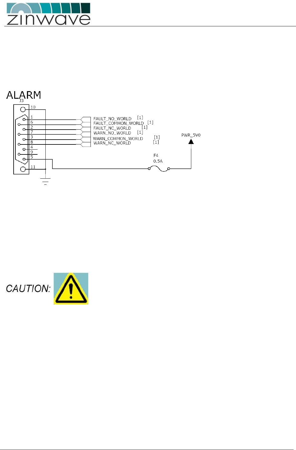
4.7.2 Serial Interface wiring diagram
UNItivity can connect to external alarm sources or monitors via the 9-way D-type connector. The connector
provides 4 relay outputs: normally open alarm; normally closed alarm; normally open warning; normally
closed warning
The relays are activated by an alarm or warning event. The relays are deactivated by clearing the alarm or
warning condition and resetting the alarm/warning filter.
Full details of alarms and functionality are provided in the “Configuration and Control Guide”.
4.7.3 Populating the UNIhub
Follow the instructions below to install any SM into the rear of the PH.
Follow the instructions below to install any OM into the front of the PH or front/rear of the SH.
OM must ONLY be installed on the front panel of a PH or the unit will
not function as expected.
UNItivity – Installation Manual
January 2016
V1.1 Page 26 of 55 January 2016
4.7.3.1 Installing a Module (general instructions)
In order to make a good signal connection, all modules are a very snug fit when you install them into a
UNIhub.
If necessary, remove any blanking panels from slots that you want to populate. To do this, remove the
retaining screw using a cross-headed screwdriver.
Carefully align and slide the module into the UNIhub.
Once the module is in place, press it home firmly with your thumbs at the top and bottom to ensure the
internal contacts mate correctly.
Replace the retaining screw and tighten using a screwdriver. This is important as modules are equipped
with floating SMA connectors at the rear which are slightly sprung to enhance connectivity. Without the
retaining screw performance may be degraded
It’s good practice to fit blanking plates (supplied) to any unused slots in the UNIhub.
When you install a module into a slot, the three LEDs on the front of the module will indicate operational
status. The UNIhub communicates with each module in turn, and cycles through the installed modules.
If no RU’s are connected, only the right and middle LEDs will be operational. The right LED will be a dull red,
indicating that power is connected but the module is disabled. This will change to green as the UNIhub
detects the presence of the module. As the UNIhub polls each of the installed modules, the right LED will
show green, and the middle LED will briefly show red.
During this period, UNIhub is checking for the presence of any RU. If none are found, the UNIhub will cycle
to the next module. If a RU is connected, during normal start up the LEDs behave as follows:
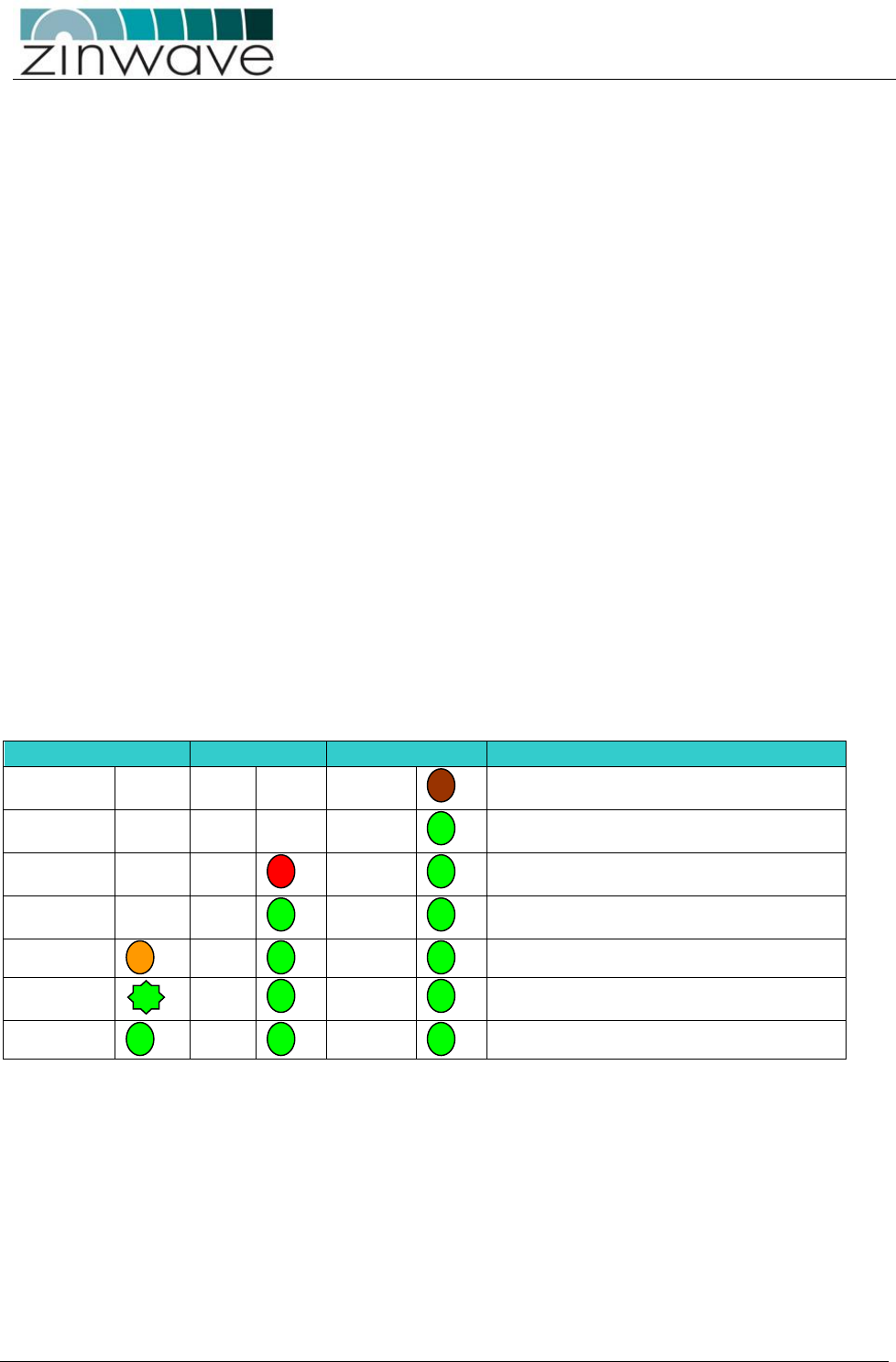
4.7.3.2 Typical Module LED status
Left
Middle
Right
Status
OFF
OFF
DULL RED.
Initial start-up. Basic Power present on UNIhub to
allow Module detection
OFF
OFF
GREEN
Module detected and full power connected to
module
OFF
RED
GREEN
Power connected but no communication
established with UNIremote
OFF
GREEN
GREEN
Power connected and communications
established with UNIremote
ORANGE
GREEN
GREEN
Optical link in calibration
GREEN FLASH
GREEN
GREEN
Calibration complete, but final output stage not
enabled
GREEN
GREEN
GREEN
Fully operational.
A fully functioning module will display three green LEDs.
There may be some variation in the exact sequence depending on the location of the unit in the system. For
full information on LED status refer to the “Configuration and Control guide”.
UNItivity – Installation Manual
January 2016
V1.1 Page 27 of 55 January 2016
4.8 Installing the SH
Essentially, this is very similar to installing a PH. The only differences are in the modules you install:
Install the SH into the 19" rack.
Provide mains power and switch on.
Ethernet connection to SH (optional).
Rear panel: Install OM.
Front panel: Install any OM to be connected to RU.
4.9 Installing the RU’s
RF Signal from UNIhub supplied via fiber.
Power supplied in one of two ways:
o Local mains, using an adaptor
o RU 48V, via a Rack-mounted Central PSU
You should mount the RU and Antennas in the locations assigned in your system installation plan. Any extra coaxial
extension cables (N-type male to N-type female)
Fiber patch cords and power connections for the RU.
3 Zinwave-specific patch cords should always be used to connect an RU to the infrastructure cable.
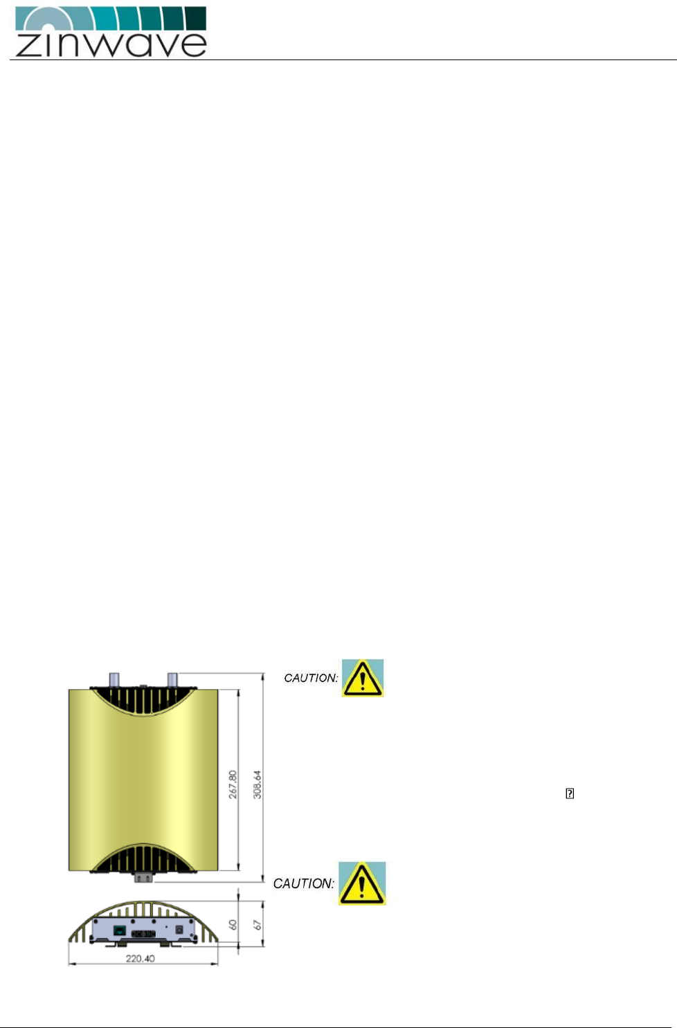
4.9.1 Mounting a UNIremote
An RU has the following dimensions
RU’s should be vertically-mounted to
ensure optimum cooling effect and to
achieve the maximum ambient
operating specification.
If the RU is mounted in the
horizontal plane the maximum
ambient operating temperature
must be relaxed by 8 C.
Avoid dust ingress to fiber
connectors by mounting the
UNIremote with the fiber connector
facing downwards, or by leaving the
dust-caps in place until the fiber is
connected.
UNItivity – Installation Manual
January 2016
V1.1 Page 28 of 55 January 2016
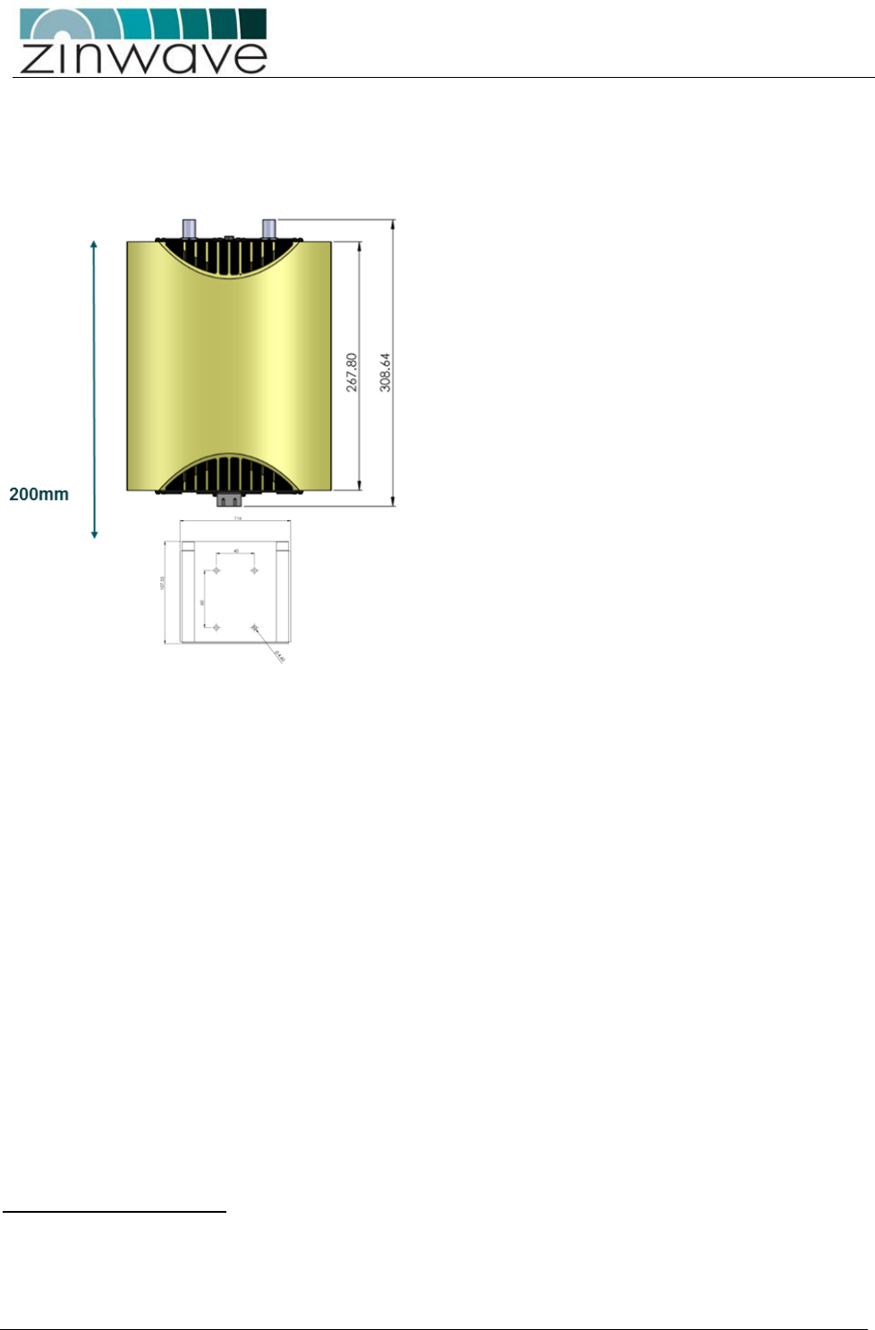
When choosing a mounting location for RU, note the following:
The bracket can be mounted with the open slot at the top or side depending upon access requirements
Allow for a minimum clearance of 180mm beyond the wall bracket’s open edge to allow for the RU to be
slotted in once the bracket is in place
Ensure that adequate space is provided to allow for any power and signal cables to be connected and
that minimum bend radii of cables are met.
Often, the RU must be sited in equipment rooms, out of sight. This also allows for easier cable routing
to the Antenna (which must exit from a hole in the ceiling).
Note which way up the bracket goes (for top or side mounting).
Offer the RU mounting bracket up to the wall.
Mark the four holes using a pencil.
Drill four M3 holes.
Fix the bracket to the wall using four M3 screws and appropriate fixings such as rawl plugs (not
supplied).
Position the RU appropriately, and then slide it into the bracket.
4.9.2 Powering an RU
An RU requires a separate power supply. This can either be from a local mains supply or from a central 48V
dc supply.
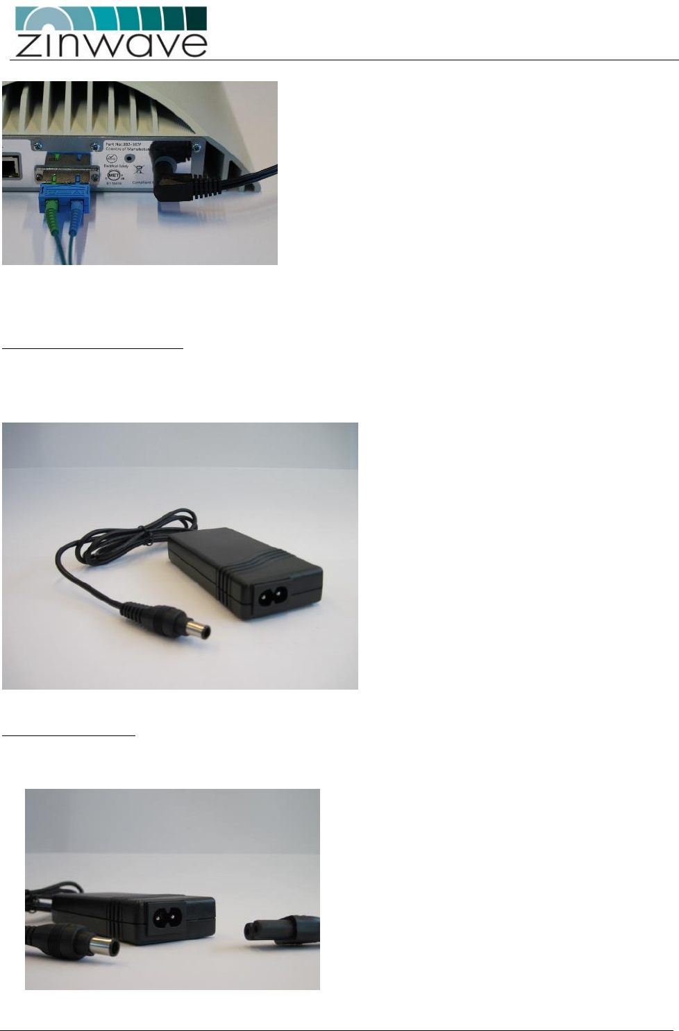
There are two variants of mains power supply. The local mains power block has been recently introduced as
a like for like replacement for the original adaptor.
Local mains Power supplies
UNItivity – Installation Manual
January 2016
V1.1 Page 29 of 55 January 2016
Both variants detailed here are provided with a pre-terminated EIAJ5 connector which plugs into the RU as
shown.
Local mains, via power block
The power block is designed for connection to a local mains supply. It is also supplied with a 2m long mains
cable with appropriate plug which terminates in a figure of 8 connector.
This allows for greater flexibility when locating the RU in relation to the mains supply.
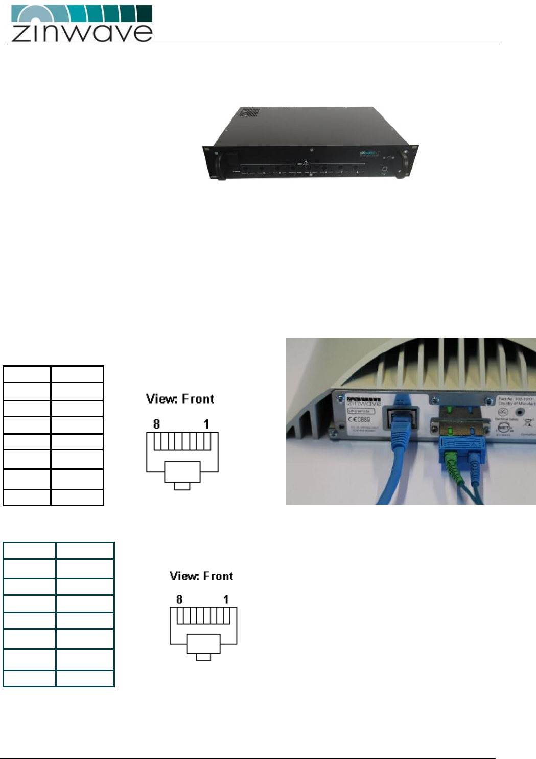
Extending Cable runs
Power blocks have a figure of 8 connector (non-polarized IEC 60320 C7) so for longer power runs a standard
“figure of eight” extension cable can be used.
UNItivity – Installation Manual
January 2016
V1.1 Page 30 of 55 January 2016
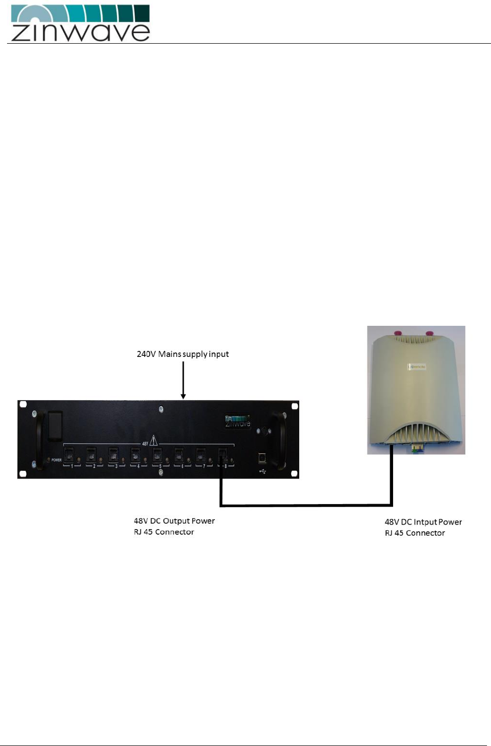
4.9.2.1 RU 48V, via Rack-mounted Central PSU
Using this connection method, you can power up to eight RU’s from a centralised location.
You will need:
One Rack-mount Central PSU
For each RU, you will require:
1 x CAT-5 cable to connect from Central PSU to RU (RJ-45 interface) (not supplied)
Proceed as follows:
Install the Rack-mount Central PSU into the rack.
Make up a CAT-5 power cable long enough to reach the RU. This should be a straight-through
configuration (you must ensure that the pin out is the same at each end).
Note: If you want to use your own 48V power supply, rather than the Rack-mount Central PSU, wire the
RJ45 connectors at each end as follows (in effect, you are making a 2-core cable):
The pin outs for the UNIremote power supply is:
PIN 1
1(A) +ve
PIN 2
1(A) +ve
PIN 3
1(B) -ve
PIN 4
2(B)-ve
PIN 5
2(B)-ve
PIN 6
1(B) -ve
PIN 7
2(A) +ve
PIN 8
2(A) +ve
The pin out for the Rack Mount power supply is:
PIN 1
1(A) +ve
PIN 2
1(A) +ve
PIN 3
1(B) -ve
PIN 4
2(B)-ve
PIN 5
2(B)-ve
PIN 6
1(B) -ve
PIN 7
2(A) +ve
PIN 8
2(A) +ve
UNItivity – Installation Manual
January 2016
V1.1 Page 31 of 55 January 2016
The wiring to the RU power supply uses two independent 48V supplies (48V1 and 48V2). Each supply has a
positive and negative line connection, and each connection is made through one pair of pins of the
Ethernet connector.
48V 1(A) (positive) pins 1,2
48V 1(B) (negative) pins 3,6
48V 2(A) (positive) pins 7,8
48V 2(B) (negative) pins 4,5
Note that the positive and negative polarity of 48V1 and 48V2 is not important and can be
independently reversed. The polarity suggested above matches the wiring of our distribution box and this
would avoid any future compatibility issues. We do need both 48V supplies to deliver the required current
and spread it across all the wires
This pin out is compatible with standard Ethernet wiring (568A and 568B) with standard straight through
cable, and both 100BaseT cross over and 1000BaseT crossover cables.
Connect pins 1, 2, 3 & 6 together
Connect pins 4, 5, 7 & 8 together
Route the cable from the PSU to the RU
Note: The centralized power supply system was developed between the ratification of IEEE 802.3af in 2003
and 802.3at in 2009.
802.3af provides up to 15.4 watts of power and 802.3at (Type 1) provides up to 25.5 watts of power. The
RU requires a maximum 30 watts of power and therefore does not conform to either standard. RU’s
requires a maximum of 2.5 amps at 12 volts and by using the four cable pairs in parallel, we do not exceed
the capability of Ethernet cable.
UNItivity – Installation Manual
January 2016
V1.1 Page 32 of 55 January 2016
5 Fiber Optic Requirements
Each fiber connection between UNIhub and RU must meet the following minimum standards and
performance criteria
Optical Loss: Less than 5dBo
Return loss for ALL connections: better than 30dB
Recommended Fiber: Single Mode
Recommended Connector Type: APC
IMPORTANT:
To achieve best performance, the system needs 30dB back reflection to be working properly, and this has
to be guaranteed throughout the entire link, so if there’s even only one interface with a lower value, the
link must be diagnosed until a value of at least 30dB is restored.
FUNDAMENTAL PRINCIPLES OF FIBER OPTIC SYSTEMS MUST BE FOLLOWED FOR EVERY INSTALLATION
Connector types must match (i.e. SC/APC to SC/APC or SC/UPC to
SC/UPC). Otherwise, there will be an air gap between the connector
faces that will create high back reflection and high optical loss.
If there is a change in fiber core diameter, light must always travel
from a smaller to a larger core diameter. Otherwise, there will be
excessive optical loss.
E.g. Single mode can transmit into multimode fiber but multimode
CANNOT transmit into single mode
Fiber handling procedures should be carefully observed so as not to
damage or introduce dirt to fiber interfaces during installation

UNItivity – Installation Manual
January 2016
V1.1 Page 33 of 55 January 2016
5.1 Fiber Optic Interface
UNItivity platform uses SC connectors on both the optical module in the UNIhub and RU.
The system uses a laser in the transmit direction and photodiode in the receive direction hence the
connectors are SC APC in the transmit direction (laser) and SC PC in receive.
With this combination the UNItivity platform can be deployed with both Single and Multimode
infrastructures, although optimum performance is obtained with single mode architecture.
The interface to infrastructure equipment is usually achieved through the use of patch cords (jumper
cables). All Zinwave supplied patch cords are provided with the correct SC/APC and SC/PC connectors for
the Zinwave equipment and connectors as specified to match the installed infrastructure.
5.1.1 Zinwave Patch cords
Zinwave patch cords are designed to have the appropriate connectors and fiber type for the OM’s and
RU’s.
All UNItivity platform use the same fiber connector:
OM’s use single mode with an SC connector with an APC Ferrule for transmit and multimode with an SC
connector with a PC ferrule on the receive direction.
Zinwave supplies the following standard Patch Cords:

UNItivity – Installation Manual
January 2016
V1.1 Page 34 of 55 January 2016
5.1.1.1 Multimode
Part Number
Zinwave
Equipment Side
Fiber Type
Patch panel side
500-0025
Transmit
SC APC
single mode
SC PC (beige)
Receive
SC PC
multimodeOM1
SC PC (beige)
5.1.1.2 Single Mode
Part Number
Zinwave
Equipment Side
Fiber Type
Patch panel side
500-0028
Transmit
SCAPC
single mode
SCPC (blue)
Receive
SCPC
single mode
SCPC (blue)
Part Number
Zinwave
Equipment Side
Fiber Type
Patch panel side
500-0029
Transmit
SCAPC
single mode
SCAPC (green)
Receive
SCPC
single mode
SCAPC (green)
It should be noted that standard patch cords terminate in SC connectors for connection to the
infrastructure cabling
Other patch cords can be supplied on request
5.1.2 Non Zinwave patch cords
Where Zinwave patch cords are not used care must be taken to ensure that the correct connector and
fiber type is provided.
Any non Zinwave patch cords must follow the same connector and fiber types as detailed below.
Note infrastructure connector is not specified but must be suitable for the fiber deployed

UNItivity – Installation Manual
January 2016
V1.1 Page 35 of 55 January 2016
5.1.2.1 Fiber and Connector Specifications for Zinwave equipment
Fiber Jumper Specification for OS1 Single-mode Plant Fiber
• Launch fiber from Zinwave equipment is OS1 Single-mode – Zinwave connector is SC/APC
• Receive fiber into Zinwave equipment is OS1 Single-mode – Zinwave connector is SC/UPC
• Fiber Jumper Specification for OM1 Multi-mode Plant Fiber
• Launch fiber from Zinwave equipment is OS1 Single-mode – Zinwave connector is SC/APC
• Receive fiber into Zinwave equipment is OM1 multi-mode – Zinwave connector is SC/UPC
• Fiber Jumper Specification for OM2 Multi-mode Plant Fiber
• Launch fiber from Zinwave equipment is OS1 Single-mode – Zinwave connector is SC/APC
• Receive fiber into Zinwave equipment is OM1 or OM2 multi-mode – Zinwave connector is SC/UPC
• Fiber Jumper Specification for OM3 Multi-mode Plant Fiber
• Launch fiber from Zinwave equipment is OS1 Single-mode – Zinwave connector is SC/APC
• Receive fiber into Zinwave equipment is OM1 or OM3 multi-mode – Zinwave connector is SC/UPC
These configurations allow connection to any intermediate fiber plant without regard to connector type. It
should be noted that UPC connectors can be mated to PC connectors as both have “flat” faces but APC
connectors MUST be mated to APC as these have angled faces
UNItivity – Installation Manual
January 2016
V1.1 Page 36 of 55 January 2016
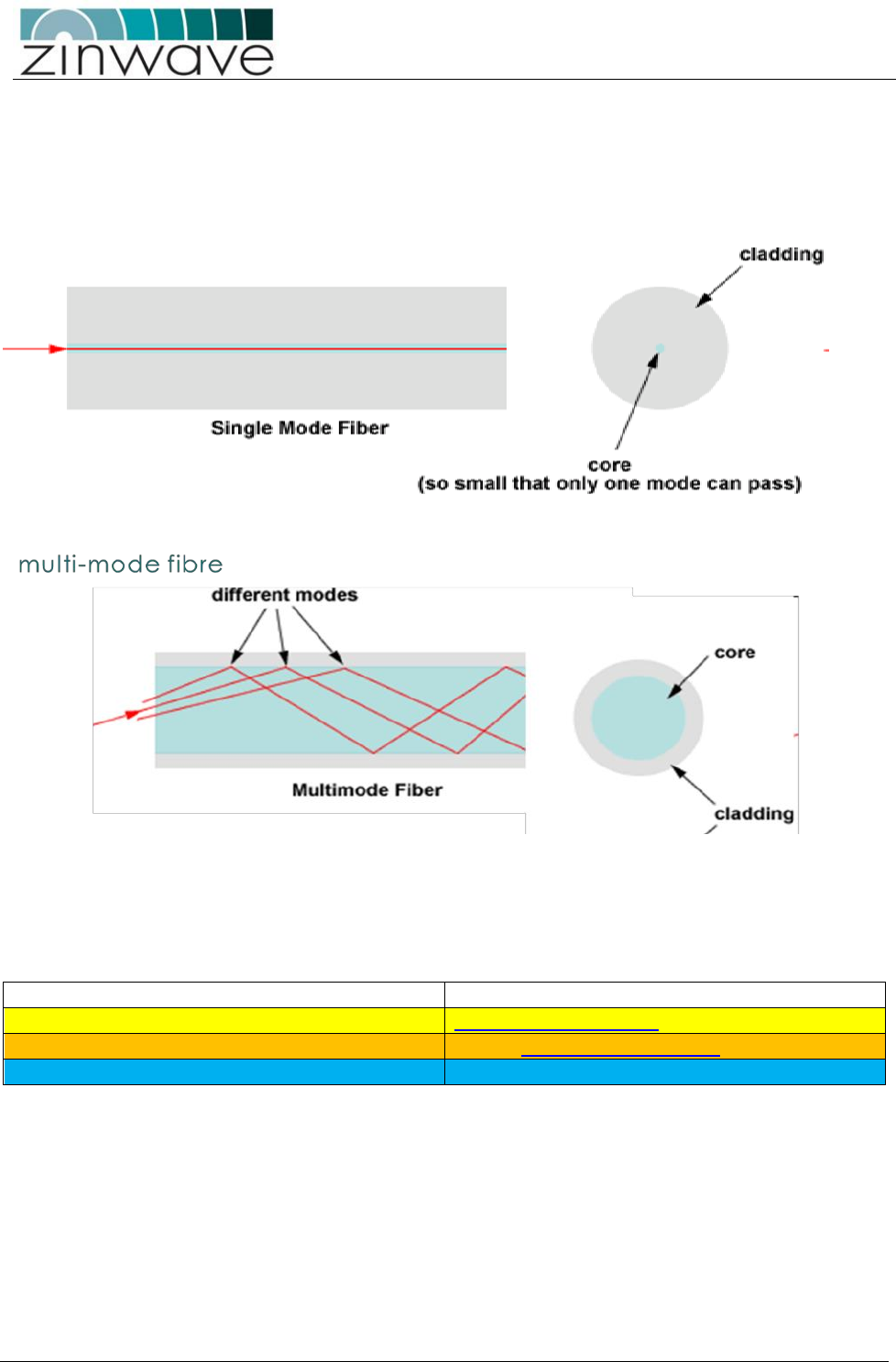
5.2 Use of Single Mode or Multimode Fiber cable
Optical fiber cable is generally available in two types: single mode and multimode.
Single mode optical fiber cables, due to the very small core size (9 µm) transmit a single ray of light whilst
multimode optical fiber cable, with a larger core size ( 62.5 µm or 50 µm), carries multiple light rays with
different reflection angles within the fiber core .
.
The presence of multiple modes in a multimode fiber means that multimode fiber installations are more
prone to internal reflections (return loss) which affects performance of the system.
The majority of reflections occur at points of fiber connection within the whole system. This includes OM
and RU but more importantly at intermediate connections such as patch panels and fiber splices
Guide to Fiber Colours
Buffer/jacket colour
Meaning
Yellow
single-mode optical fiber
Orange
62.5 µm multi-mode optical fiber
Light Blue/ Aqua
50/125 µm micrometre multi-mode
UNItivity – Installation Manual
January 2016
V1.1 Page 37 of 55 January 2016
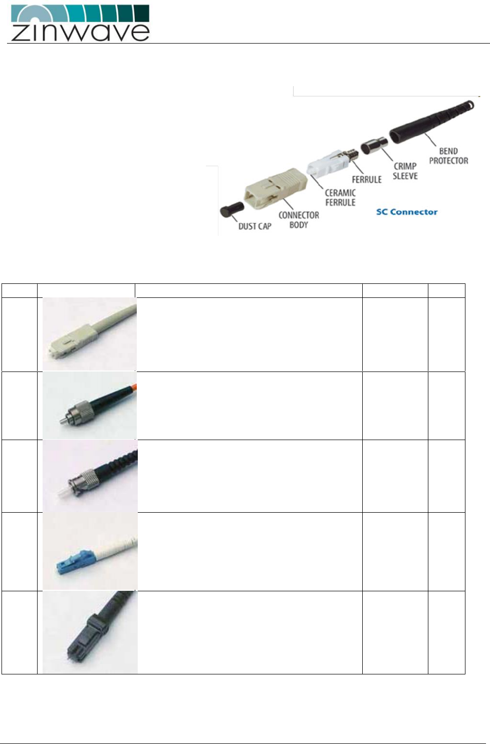
5.3 Fiber optic Connectors
A fiber optic connector consists of two key
elements.
Connector body Type
Ferrule Type
There are a wide variety of connector body
types used in infrastructure cabling some
of the most common types are shown
below.
There are two main groupings standard and
Small Form factor. The small form factor
connectors have a 1.25mm ferule compared
to the ferule size in “standard connectors of
2.5mm.
Zinwave recommends the use of APC connector type
Type
Description
Cable Type
APC
SC
SC is a snap-in connector that is widely used in
single mode systems for its excellent
performance. It's a snap-in connector that
latches with a simple push-pull motion. It is
available in both PC, UPC and APC
Single
Mode and
Multimode
Yes
FC
Commonly used in single mode networks and is
available in PC, UPC and APC variants. It has an
outer body that screws in to hold the ferule
firmly in place. It has a key ensuring that the
fiber is correctly aligned.
Single
Mode and
Multimode
Yes
ST
Popular connector for multimode networks. It
has a bayonet mount and a long cylindrical
ferrule to hold the fiber. The main body is
spring loaded and can cause problems (high
loss) if not seated properly.
single mode
and
multimode
No
LC
LC is a new connector that uses a 1.25 mm
ferrule, half the size of the ST.
single mode
and
multimode
YES
MTRJ
MT-RJ is a duplex connector with both fibers in
a single polymer ferrule. It uses pins for
alignment and has male and female versions.
Multimode only
Multimode
only
NO
UNItivity – Installation Manual
January 2016
V1.1 Page 38 of 55 January 2016
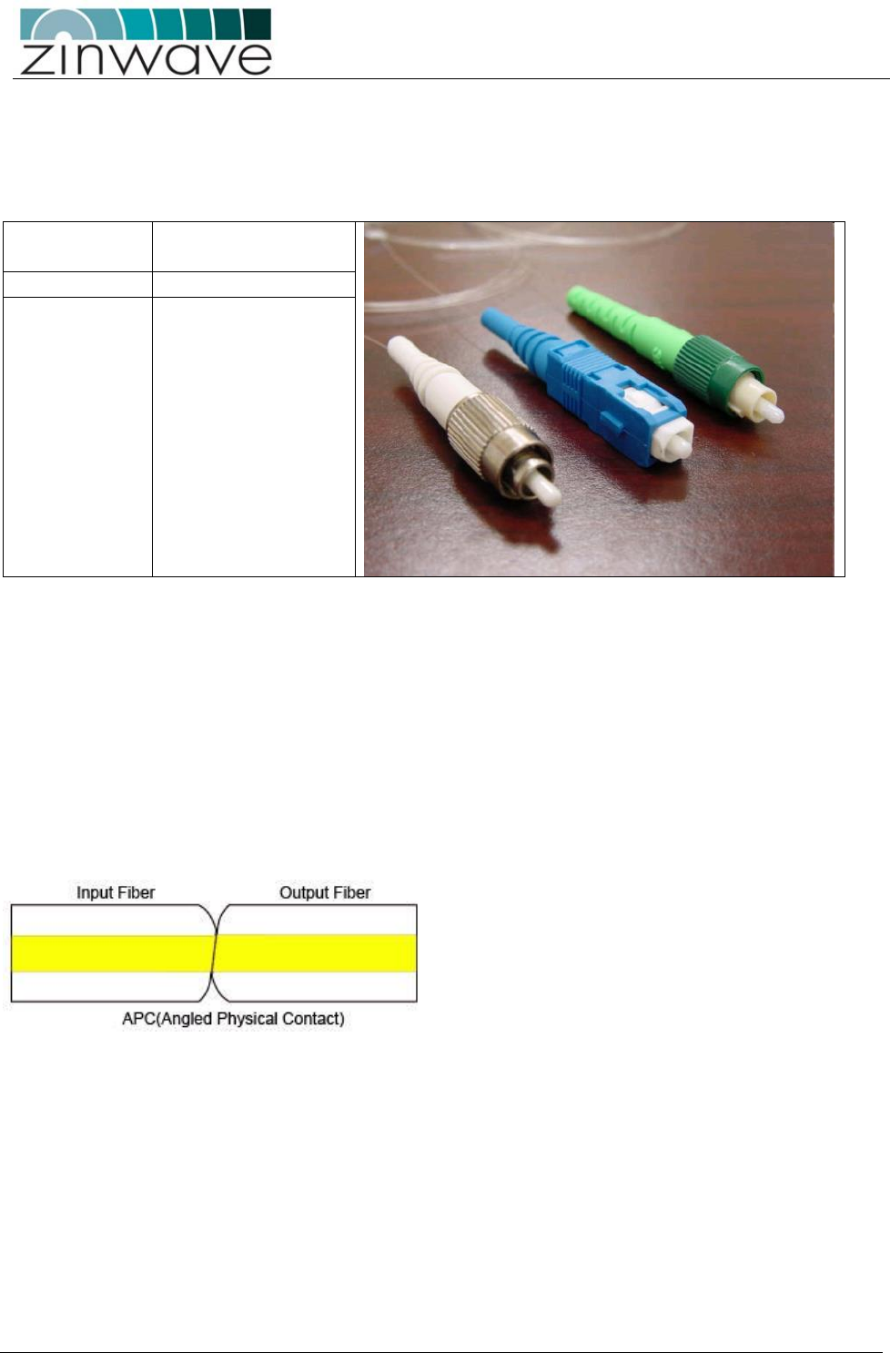
5.4 Ferrule Types
As shown above some of these connectors can be designated either APC or PC, this refers to the Ferrule
within the connector body. The TIA 568 colour code for connector bodies and/or boots is:
Green
Single mode APC
(angled) connectors
Blue
Single mode (UPC)
Beige
multimode
Attaching a connector to an optical fiber cable will cause some of the light traversing that optical fiber to be
lost. Regardless of whether the connector was installed in the factory or the field, its presence will be
responsible for some light being reflected back towards its source, the laser. This is known as return loss
(RL) and high levels of unwanted reflections can degrade the signal’s performance.
The amount of optical return loss generated is related to the type of polish that is used on the connector.
There are three basic types of polish:
APC
UPC
PC
5.4.1 APC (Angled Physical Contact)
The “angled physical contact” (APC) connector is best as it offers the lowest return loss characteristics of
connectors currently available. In an APC connector, the end face of a termination is polished precisely at
an 8-degree angle to the fiber cladding so that most RL is reflected into the cladding where it cannot
interfere with the laser source.
As a result, APC connectors offer a superior RL performance with atypical back reflection of better than
60dB
UNItivity – Installation Manual
January 2016
V1.1 Page 39 of 55 January 2016
5.4.2 UPC (Ultra-polished Physical Contact)
Typical Back Reflection: <-35dB for single mode fiber
UPC connectors are very similar to PC connectors in that the ferrules faces are flats but have a much better
return loss, which can be better than 50 dB. This performance is due to an improved polishing technique
applied to the face and to the curvature at the ferrule end. The rounded finish created during the polishing
process allows fibers to touch on a highpoint near the fiber core where light travels UPC polish is available
for almost all single mode connectors--namely FC, SC, ST, but, unlike PC connectors, is not available for
multimode fibers.
When using UPC connectors it is essential to confirm optical back-reflection levels using an OTDR as
described in the sections below.
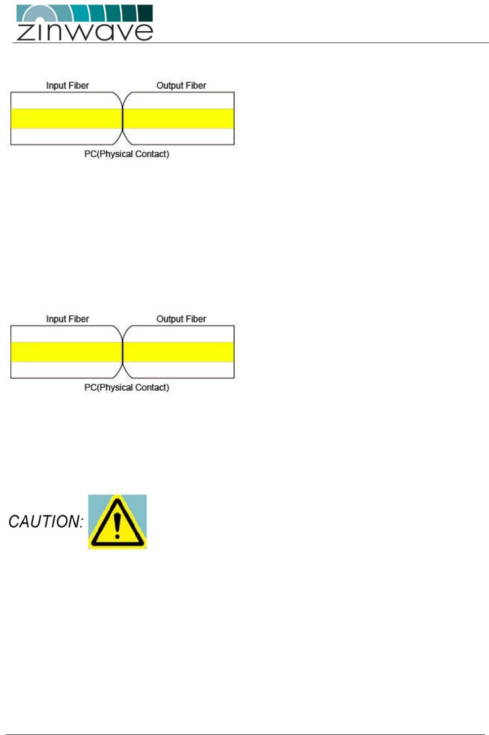
5.4.3 PC (Physical Contact)
Typical Back Reflection: <-35dB for single mode fiber
The “physical contact” (PC) connector is probably the most common type of ferrule face. It is available on
both single mode and multimode fibers but due to the flat face has reduced eturn loss and is more prone to
dirt and poor connections
When using PC connectors it is essential to confirm optical back-reflection levels using an OTDR as
described in the sections below.
NOTE: UPC can be mated to PC connectors as both have flat faces but
APC connectors can only be connected to APC connectors due to the
face angle
5.4.4 Effects of Back Reflections on system performance
In presence of high levels of back reflection due to poor Return loss the Zinwave system performance is
degraded. The effects of this can be easily seen on the system and diagnosed using appropriate test
equipment. The effects of back reflection can be seen by looking at the level of the noise floor. In cases
where there are high levels of back reflection, the noise floor in either the downlink or the uplink can vary
significantly (10-15dB). It may also show as increased levels of harmonics which will also vary in level by
significant amounts.
UNItivity – Installation Manual
January 2016
V1.1 Page 40 of 55 January 2016
5.4.4.1 How to diagnose an optical link with an OTDR
The best way to check the return loss of a fiber link is to use an Optical Time Domain Reflectometer with
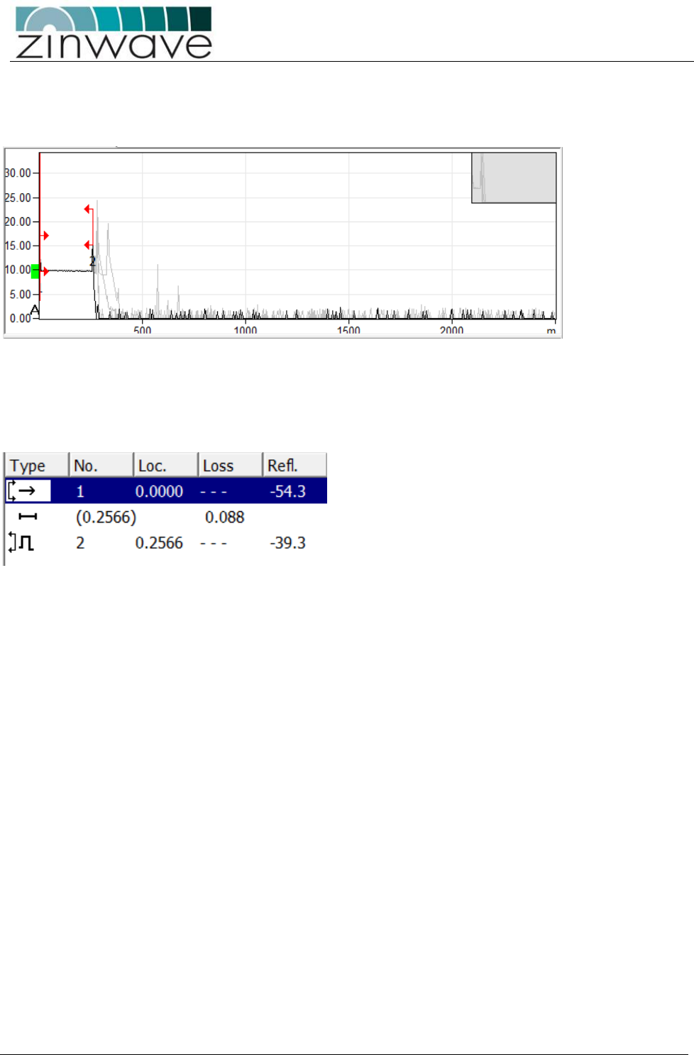
the appropriate connectors and launch cables. A typical graph result is shown below:
The graph shows the performance of fiber along its length. In this case the first horizontal line represents
the first 250m of fiber in the launch box. Each of the subsequent peaks relates to the situations where
internal reflection has occurred along the fiber length. This could be connectors, splices or even damaged
cables. Generally the highest peak shows the worst case of back reflection and hence source of return loss
and potential interference, depending on the OTDR used results, can be displayed in a tabular form giving
distances and the relevant reflection or return loss.
In the example above a single reflection of -39.3dB is present. In this case the -39.3dB reflection is at the
PC/PC interface at the end of the link and in a link with multiple connections there will be an event for each
connection.
It should be noted that the OTDR is not able to distinguish between 2 reflections very close to each other
over long lengths of cable and in the case of two reflections close together, only the worst reflection will be
shown. However this will allow installers to identify where in the overall fiber link the problem occurs.

UNItivity – Installation Manual
January 2016
V1.1 Page 41 of 55 January 2016
5.4.5 Fiber Inspection and Cleaning
5.4.5.1 Inspection
The optical fiber connection has two basic performance indicators: Insertion Loss and Return Loss. Poor
performance in either of these areas will degrade the overall system performance
Insertion loss
The optical loss can be seen for each link by looking at the status page of the web GUI and examining each
connection in turn or alternatively making a dump of the entire system data and examining it through the
layout tool.
This can be caused by a number of problems (most of which can be resolved simply):
Incorrectly mated connectors: An incorrectly mated connector will cause either a misalignment of
the optical fiber or an air gap between the two ferrule faces. In either case a high insertion loss will
be seen.
Dirty Connectors: dirt on the face of optical connectors will cause higher insertion loss, which can
be reduced by careful cleaning of the fibers.
Poor splice assembly. In some cases infrastructure will include splices. These can, if done poorly,
show up as high insertion loss. (They will also cause poor return loss). If the insertion loss is due to
a poor splice then it must be remade correctly.
Optical Return Loss (Back Reflections)
This is easily tested by using an OTDR instrument, although the symptoms as described above can be seen
by looking at the RF output with a spectrum analyser. The cause of poor back reflections can be caused by:
Poor or incorrect connector types. APC connectors will not cause back reflections but with PC
connectors careful attention must be paid to the return loss specification and great care must be
taken when handling connectors to ensure that dirt is not present which can also affect return loss
Tight fiber bends: If a fiber is bent too tightly then it is possible to cause internal reflections. When
installing fibers, and particularly when storing excess fiber, always observe the minimum bend
radius specified. These are easily seen with a VFL (visual fault locator). These usually use a visible
red laser which will clearly show up fiber breaks, severe bends and faulty connectors
Dirty fibers (Causing Loss and Back Reflections issues)
UNItivity – Installation Manual
January 2016
V1.1 Page 42 of 55 January 2016
5.4.5.2 Cleaning Fibers
Clean fibers are important in all installations but in multimode installations this is even more important.
Ideally all fibers should be visually inspected as this gives a very clear indication of dirt on fibers.
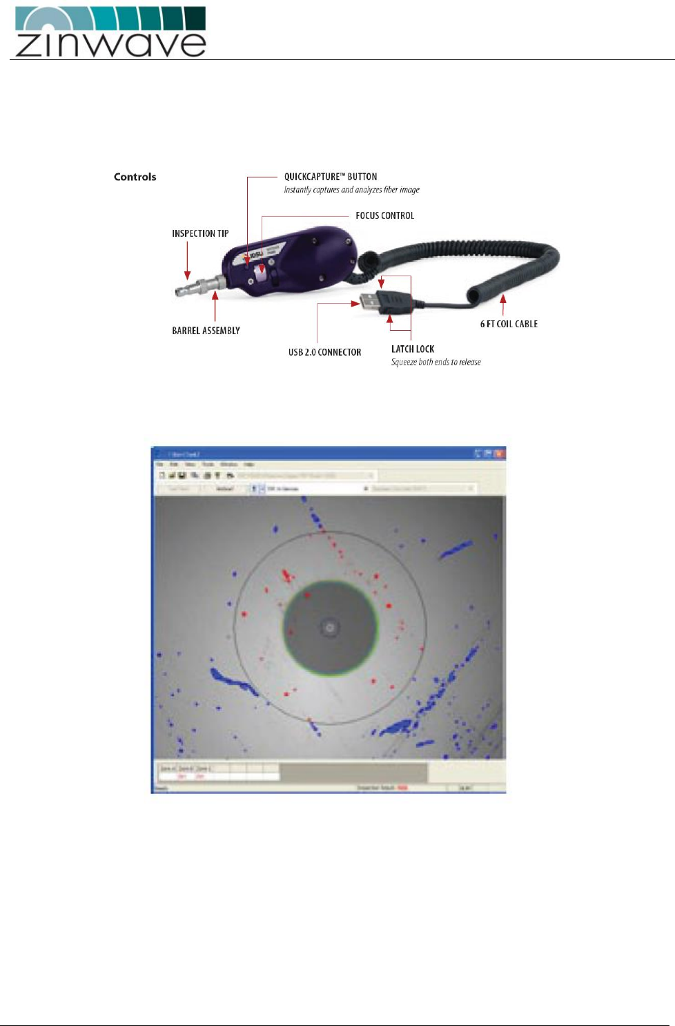
There are many optical inspection tools such as the one shown below:
With the inspection tool shown above which connects to a PC the image of the fiber can be captured and
examined prior to cleaning.
Note that special tips are required to inspect APC connectors due to the angle of the connector face
However, the fiber must be clean enough so that <-30dB ORL threshold is maintained on the optical link.
Dry Cleaning – This is the most common type of cleaning method. Normally, just a single-click cleaner
device is used or the dry cloth. This method is effective for new/better maintained fibers.
Wet Cleaning – This method is more effective on used or poorly maintained fibers which require a great
deal of cleaning. If the dirt cannot be removed by using dry cleaning methods, special wet wipes, usually
alcohol based, can be used to clean the face followed by ideally a dry wipe action such as single-click
cleaner to effectively wipe off the dirt speckles.

UNItivity – Installation Manual
January 2016
V1.1 Page 43 of 55 January 2016
6 Making the signal connections
Observe safety precautions when working with fiber cables and
devices (see Optical Safety Precautions on page 6).
Both transmit and receive are SC Connectors.
All optical devices require a Zinwave patch cord irrespective of the
existing or installed fiber and connector type.
Connecting Fiber Cables
UNItivity platform uses fiber optic cables to connect UNIhub (OM) and RU. As with any fiber based
system the use of fiber optic cable calls for careful attention to cleanliness and good installation
practice.
UNItivity platform will achieve optimal performance when using single mode cable and APC
connectors but can, with careful consideration, be used with multimode fibers.
The Infrastructure Cable between UNIhub (OM) and RU must meet the following specifications:
Maximum Optical Loss 5dBo
Minimum Optical Return Loss 30dB
This can be guaranteed with single mode fiber and APC connections throughout the installation.
UNItivity – Installation Manual
January 2016
V1.1 Page 44 of 55 January 2016
6.1 Connecting UNIhub to the fiber infrastructure
Follow these instructions for each Optical Module in the UNIhub
OM’s use Single Mode on Transmit (APC) and Multimode on the
receive direction (PC).
Both transmit and receive ports are SC Connectors
All OM’s and RU’s require a Zinwave patch cord irrespective of the
existing or installed fiber and connector type.
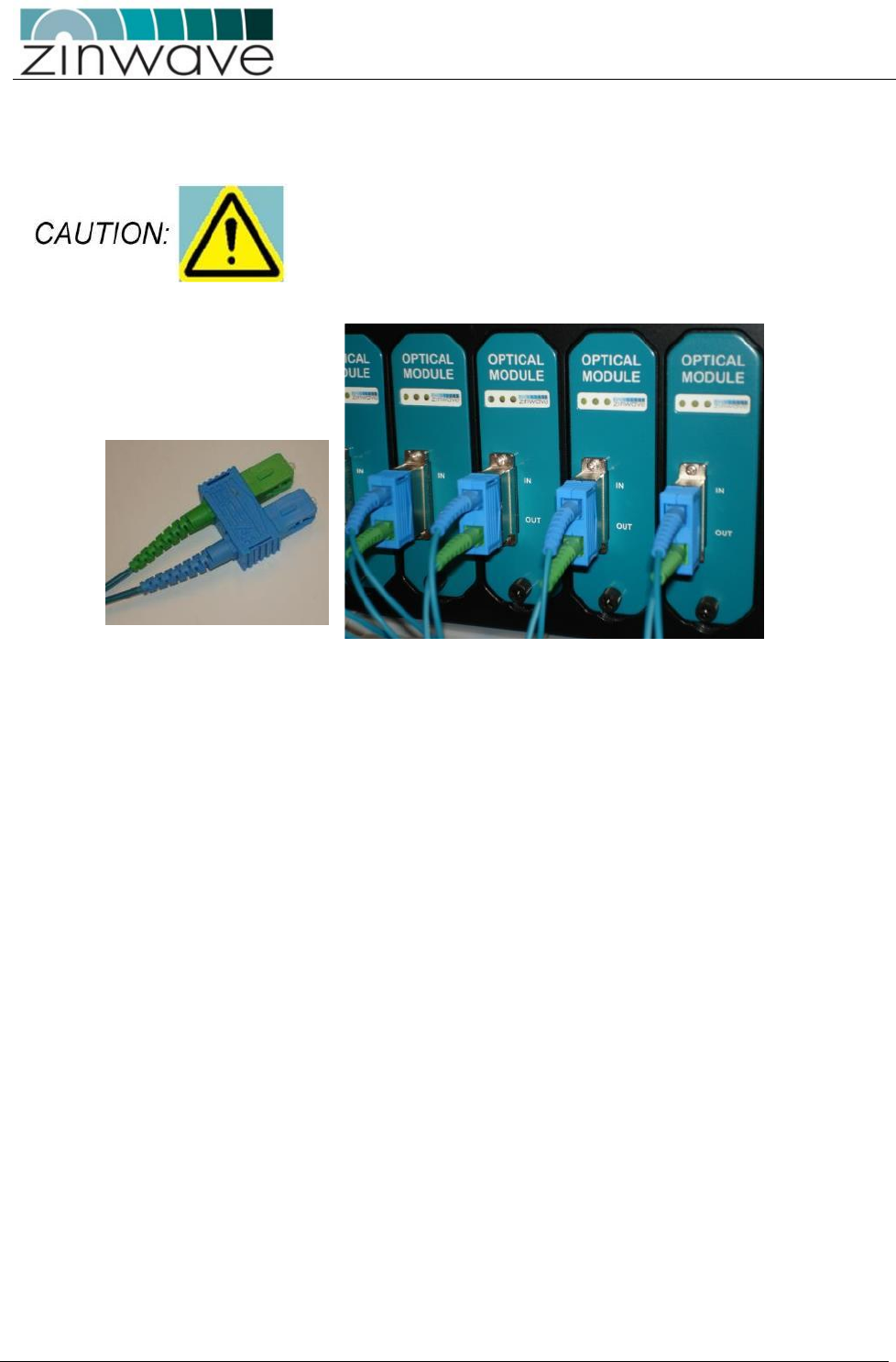
Remove the protectors from the SC connectors on the OM and the Zinwave patch cord.
Plug the green/blue end of the Zinwave SC optical patch cable into the OM. It is vital that you fit this
connector the right way up (blue tag at the top, as shown). Incorrect installation will damage the ends
of the fiber.
Connect the other end of the patch cable to your fiber infrastructure (this will usually be via a fiber
patch panel).
UNItivity – Installation Manual
January 2016
V1.1 Page 45 of 55 January 2016
6.1.1 Connecting UNIhub to an RU
OM’s use Single Mode on Transmit (APC) and Multimode on the receive direction (PC).
Both transmit and receive are SC Connectors.
All optical devices require a Zinwave patch cord irrespective of the
existing or installed fiber and connector type.
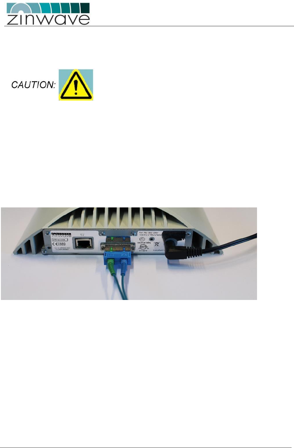
Install fiber-optic cable of sufficient length to reach the RU. The cable must be terminated in a
standard SC connector (you will use a Zinwave patch cord to connect from your fiber cable to the
RU).
Remove the protectors from the SC connectors on the fiber infrastructure cable and the Zinwave
patch cord.
Plug the green/blue end of the Zinwave SC optical patch cable into the RU. It is vital that you fit this
connector the right way round (as shown below). Incorrect installation will damage the ends of the
fiber.
Connect the other end of the patch cable to your fiber infrastructure cable.

UNItivity – Installation Manual
January 2016
V1.1 Page 46 of 55 January 2016
6.1.2 Connecting an RU to Antennas
The RU has separate connectors for transmit and receive antennas.
As stated previously, the choice of antenna will depend upon the RF coverage and planned design for a
building. This may involve using extension cables where antennas are distant from the RU.
When connecting cables to the RU careful attention should be paid to the mechanical stress placed on the
connector from using large inflexible cable. Short flexible jumpers should be used where appropriate.
It is important to ensure that adequate isolation exists between Tx and Rx antennas
Connect the two N-type male connectors to the top of the RU.
If you haven’t already done so, feed the RF extension cables through from the RU to the Antenna.
Connect the two N-type female connectors to the Antenna RF tails.

UNItivity – Installation Manual
January 2016
V1.1 Page 47 of 55 January 2016
6.2 Connecting SM Inputs
You can connect SM inputs (e.g. BDA, BTS, WLAN access point) only to the PH: When connecting cables to
the SM, careful attention should be paid to the mechanical stress placed on the connector from using large
inflexible cable.
Short flexible jumpers should be used where appropriate.
Make N-type male connections to the N-type female connectors on the SM (on the rear of the PH).
UNItivity – Installation Manual
January 2016
V1.1 Page 48 of 55 January 2016
7 Antennas
UNItivity can use a variety of antennas connected to the RU via coaxial cable. The choice of
Antenna will depend on the service requirement within the operational bandwidth of the system.
7.1 Installation of two antennas
As mentioned above, a pair of off-the-shelf antennas can be used to provide separated transmit (TX) and
receive (RX). Any type or frequency of antennas can be used as long as they support the services carried by
the UNItivity and can be installed to provide sufficient isolation between TX and RX.
7.1.1 TX-RX isolation
The minimum isolation between TX and RX required for correct operation of UNItivity in both the uplink
and downlink service bands is usually 40dB (this requirement should be confirmed for any given installation
within the Zinwave Coverage Tool). However, performance (uplink noise and downlink inter-mode
interference) of the system can be improved if greater isolation is achieved. Isolation between the
antennas is achieved by separating them at a sufficient distance to achieve at least 40dB at the lowest
frequency service in use.
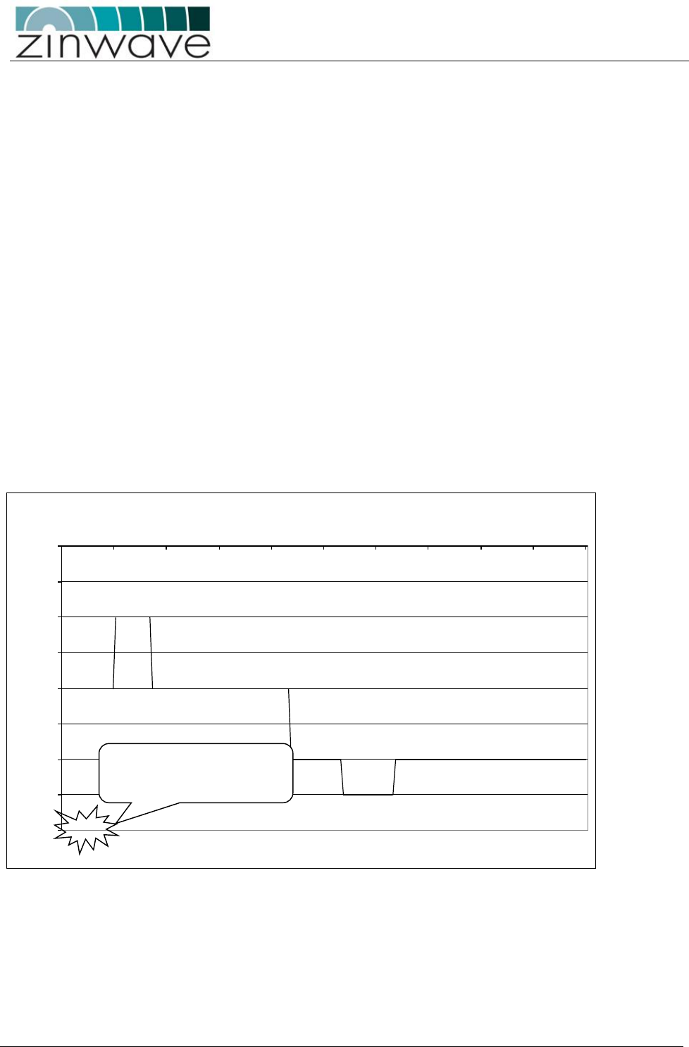
In addition to the 40dB service isolation described above, a minimum isolation must be achieved within the
entire UNItivity passband according to the graph below:
It has been found empirically that omni-directional antennas supporting the Cellular bands from 700MHz
and above require a horizontal separation distance of approximately 20’. An example of the isolation that
can be achieved using a wideband (LTE, CELL, PCS, AWS) antenna is shown below:
Antenna Minimum Required Isolation
-40
-35
-30
-25
-20
-15
-10
-5
0
0300 600 900 1200 1500 1800 2100 2400 2700 3000
Frequency (MHz)
Isolation (dB)
NB: -40dB is typical
service
isolation
required
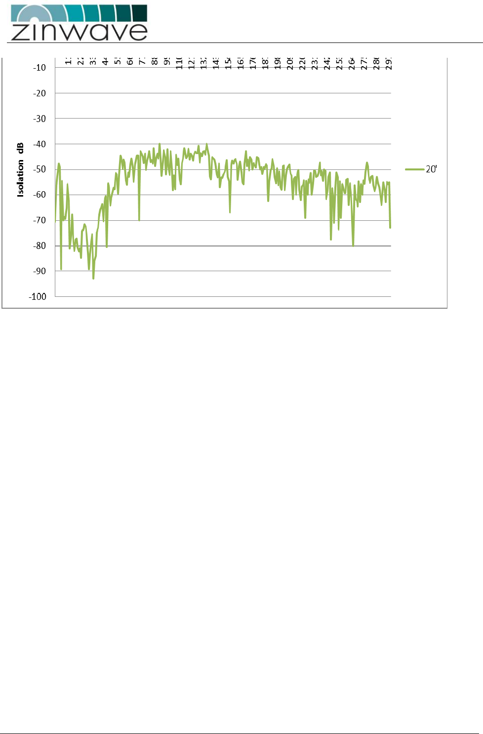
UNItivity – Installation Manual
January 2016
V1.1 Page 49 of 55 January 2016
It can be seen that the isolation improves with frequency due to the increasing propagation loss, so that the
PCS and AWS bands have isolation in excess of 45dB when the CELL band is below 40dB.
Although this distance provides a rule of thumb for initial planning, the particular antennas in use and the
environment in which they are installed will affect the isolation. It is therefore recommended to check the
measure the isolation of each antenna pair (see isolation measurement section below) prior to enabling
service operation.
With directional antennas care should also be taken to ensure the high-gain propagation direction is
oriented towards the coverage area and the low-gain (“null”) propagation direction is oriented towards the
2nd antenna. The effect of this null will be to reduce the distance between the antennas required to achieve
the 40dB isolation.

UNItivity – Installation Manual
January 2016
V1.1 Page 50 of 55 January 2016
7.1.2 Uplink/Downlink Balance
Care should be taken not to separate the two antennas by so much distance that the path difference
between TX and RX to the mobile affects system performance. Some services are more affected by
uplink/downlink path difference than others, especially those using high dynamic range mobile power-
control such as WCDMA.
There are two WCDMA system effects to be aware of when testing a separated antenna coverage area:
1. When the mobile is close to the TX antenna but some distance from the RX antenna, the initial call-
setup power that the mobile transmits will be lower than expected by the BTS. It is likely that the BTS
will fail to receive the initial call-setup attempt so the mobile will transmit again at a higher power level.
The mobile will continue to ramp up its power level until the BTS receives and acknowledges the
message. This effect can cause longer initial setup times close to the TX antenna and in extreme cases
may cause the mobile to timeout during call setup. In order to compensate for this effect the balance of
gain between uplink and downlink can be adjusted to increase the uplink gain. This is usually done in
the head-end by moving attenuation from the uplink to downlink paths. However, in some case the
UL/DL balance setting can also be used within the UNItivity platform if the uplink gain is not already at
maximum.
2. When the mobile is close to the RX antenna but some distance from the TX antenna, the initial call-
setup power that the mobile transmits will be higher than expected by the BTS. As long as the mobile
power does not overload either the RU or the BTS input then this should not cause a call setup failure.
Note that the path difference between TX and RX at the edge-of-cell is likely to be much smaller than near
the antennas due to the effect of the indoor propagation conditions. Where there are no line-of-sight
differences between TX and RX the edge-of-cell path difference will be less than 3dB for most services.
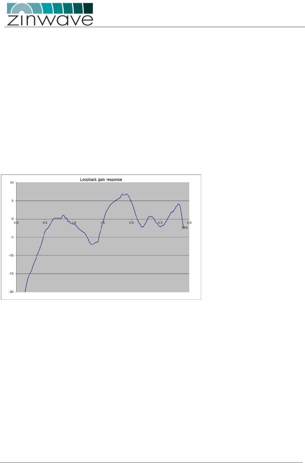
UNItivity – Installation Manual
January 2016
V1.1 Page 51 of 55 January 2016
7.1.3 Isolation Measurement Techniques
The most accurate way of measuring the antenna isolation, is to disconnect the cables at the RU antenna
ports and connect these directly to either a network analyser or a spectrum analyser with a tracking
generator. Every antenna in the installation should meet the requirements of the TX-RX Isolation section
above.
Where many antennas within an installation are being checked it is recommended to enter a test mask in
the test equipment.
Where it is not possible to access all antennas in this way, it is possible to check the isolation using
measurements at the UNIhub. However, in this case the gain profile of the uplink and downlink paths must
be removed from the measured values in order to reveal the actual antenna isolation. It is recommended
that a single path is measured with either a known good antenna or a fixed attenuator in order to obtain
this “loopback calibration” result. Then all individual antennas can be compared to this known good result
to identify and problem locations.
An example loopback (downlink+uplink) gain profile is shown in the graph below:
This graph was obtained by injecting a signal into a double-star system with 1 RU. The RU had a 50dB
attenuator connected between TX antenna output and RX antenna input. The test signal was injected into
the SM input and the resulting signal was measured at the SM output. The system settings were set such
that the downlink gain was 25dB (nominal) and the uplink gain was also 25dB (nominal). Therefore the
nominal loop gain was +25+25-50 = 0dB. The differences from this nominal 0dB that are due to the system
gain variation would then have to be subtracted from the gain variations that would be measured if the
50dB attenuator was replaced with an antenna.
It is also possible to measure multiple antennas simultaneously as long as the “combining gain” of multiple
antennas is taken into account (approximately 5dB for 8x RU and 10dB for 64 RU or more generally
2.4*ln(N) for N* RU). This method produces a much less accurate result but is a quicker way of verifying a
larger number of antennas simultaneously.
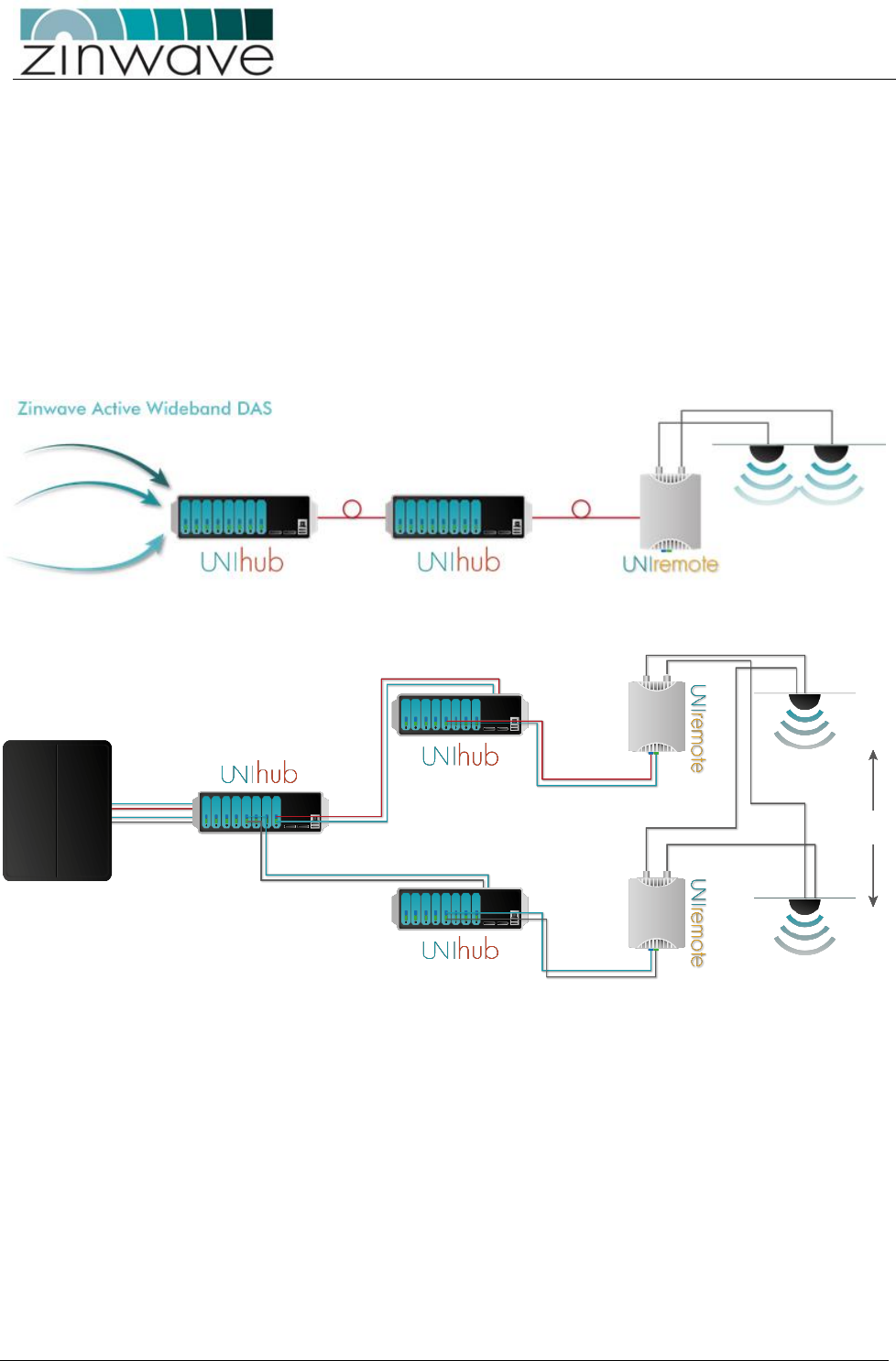
UNItivity – Installation Manual
January 2016
V1.1 Page 52 of 55 January 2016
8 UNItivity platform support for MIMO services
The next generation of high data-rate services such as WiMAX and LTE provide various MIMO options.
Where base stations (BTS) are deployed to provide in-building coverage, these options can be used to
increase the overall capacity or coverage of the system.
Typically BTS signals are distributed inside buildings via a Distributed Antenna System (DAS) which has
multiple antenna locations to provide multiple copies of each signal. In the case of MIMO each antenna
location will require 2 or more independent signals from the same BTS. The figure below shows a
comparison between the UNItivity architecture required to support a traditional single signal (SISO) BTS
and a dual-transceiver (MIMO) BTS:
In the diagram only a single antenna location is shown but the architecture can be extended to multiple SH
(up to 8 per PH) and multiple RU (up to 8 per SH). The MIMO architecture shown can support up to 32
antenna locations per PH and up to 4 independent MIMO signals (although only 2 signals are shown).

UNItivity – Installation Manual
January 2016
V1.1 Page 53 of 55 January 2016
The following considerations should be taken into account when implementing a MIMO architecture with
the UNItivity platform:
• The separation between the dual-port antennas at the same location needs to be sufficient to
provide both MIMO diversity (using guidelines provided by the BTS manufacturer) and TX-RX
isolation. Each antenna pair provides at least 40dB of isolation between the TX and RX ports of the
same RU and the separation must provide the same or better isolation between TX and RX ports of
RU A and B.
• The difference between the two path distances (which may affect time delay) between the BTS and
the antennas at any given location must be within the guidelines provided by the BTS
manufacturer. This can be achieved by ensuring that the connecting fiber paths from UNIhub to the
RU are by multi-core fibers with the same overall distance including the length of any patch cords.
Ideally the coaxial connection to the MIMO antenna pairs should also be connected directly to the
RU using their integrated flying leads to ensure no delay is introduced in the final coaxial stage.

UNItivity – Installation Manual
January 2016
V1.1 Page 54 of 55 January 2016
9 Abbreviations
µm
Micron, 1x10⁻⁶ metres
nm
Nanometre (1x 10⁻⁹ metre)
A
Amp
PC
Physical Contact
AC
Alternating Current
PCS
Personal Communications System
APC
Angled Physical Contact
PH
UNIhub configured as a Primary
AWS
Advanced Wireless Services
PSU
Power Supply Unit
BDA
Bi-Directional Amplifier
RF
Radio Frequency
BTS
Base Transceiver System
RJ45
Registered Jack 45
CAT-5
Category 5
UNIremote
UNIremote
CE
Conformity European
Rx
Receive
Coax
Coaxial
SC-APC
Standard Connector/ Angled Physical Contact
DAS
Distributed Antenna System
SH
UNIhub configured as a Secondary
dB
Decibel
SM
Single Mode
dBm
Decibel referenced to a milliwatt
SMF
Single Mode Fiber
dBo
Decibel reference to Optical loss / gain
SMR
Specialized Mobile Radio
DC
Direct Current
SNMP
Simple network Management Protocol
EIAJ
Electronic Industries Association of Japan
Tx
Transmit
EMS
Element Management System
Tma
Maximum ambient temperature
EN
European Norm
TDD
Time division duplex
FCC
Federal Communications Commission
UMTS
Universal Mobile Telephone System
FDA
Food and Drug Administration
V
Volt
FDD
Frequency Division Duplex
Wi-Fi
Wireless Fidelity
FSL
Free Space Loss
WiMAX
Worldwide Interoperability for Microwave
Access
GSM
Global System for Mobile Communication
WLAN
Wireless Local area network
HW
Hardware
kg
Kilogram ( 1x10³ grams)
km
Kilometre ( 1x10³ metres)
IEC
International Electrotechnical Commission
ISM
Industrial Scientific and Medical
LED
Light Emitting Diode
m
Metre ( 1x10³ millimetres)
LTE
Long Term Evolution
mm
millimetre
MHz
Megahertz
MM
Multimode
MMF
Multimode Fiber

UNItivity – Installation Manual
January 2016
V1.1 Page 55 of 55 January 2016
10 Revision History
Version
Date
Author
Changes
Version 1.0
Oct 2015
BA/MC
Revisions to reflect introduction
of UNIhub and UNIremote with
internal 48V PSU.
Version 1.1
Jan 2016
BA
Revisions to reflect introduction
of V4 UNIremote and software
Version 4.51