Zinwell ZW-2000-22 2.4G OutDoor Device User Manual ZW 2000 Manual 0727
Zinwell Corporation 2.4G OutDoor Device ZW 2000 Manual 0727
Zinwell >
Contents
- 1. Users Manual 1
- 2. Users Manual 2
- 3. Users Manual 3
Users Manual 1

Wireless LAN Device Series
WLAN Outdoor Bridge
ZW-2000-IA User Manual
Version.
1
TABLE OF CONTENTS
PREFACE.................................................................................................................................................................3
CH 1. ZW-2000 INSTALLATION....................................................................................................................4
PACKING LIST .......................................................................................................................................................4
HARDWARE INSTALLATION................................................................................................................................5
CH 2. FIRST TIME CONFIGURATION........................................................................................................8
BEFORE START TO CONFIGURE...........................................................................................................................8
KNOWING THE NETWORK APPLICATION...........................................................................................................8
ADVANCED SETTINGS ........................................................................................................................................31
CONFIGURING WIRELESS SECURITY...............................................................................................................34
CONFIGURING AS WLAN CLIENT ADAPTER..................................................................................................37
QUICK START TO CONFIGURE............................................................................................................................37
CONFIGURING UNIVERSAL REPEATER.............................................................................................................40
CH 3. CONFIGURING WDS...........................................................................................................................42
WDS NETWORK TOPOLOGY..............................................................................................................................42
WDS A PPLICATION............................................................................................................................................44
CH 4. ADVANCED CONFIGURATIONS....................................................................................................46
CONFIGURING LAN TO WAN FIREWALL.......................................................................................................46
PORT FILTERING..................................................................................................................................................46
IP FILTERING.......................................................................................................................................................47
MAC FILTERING.................................................................................................................................................48
NAT (NETWORK ADDRESS TRANSLATION)....................................................................................................49
CONFIGURING PORT FORWARDING (VIRTUAL SERVER).......................................................................................49
MULTIPLE SERVERS BEHIND NAT EXAMPLE:................................................................................................50
CONFIGURING DMZ ..........................................................................................................................................50
CONFIGURING WAN INTERFACE......................................................................................................................51
STATIC IP .............................................................................................................................................................51
DHCP CLIENT (DYNAMIC IP)..........................................................................................................................52
PPPOE..................................................................................................................................................................53
PPTP ....................................................................................................................................................................54
CONFIGURING CLONE MAC A DDRESS...........................................................................................................55
CONFIGURING DHCP SERVER..........................................................................................................................57
BANDWIDTH CONTROL......................................................................................................................................57
QOS (QUALITY OF SERVICE)............................................................................................................................59
STATIC ROUTE SETUP ........................................................................................................................................64
DYNAMIC ROUTE SETUP ...................................................................................................................................65
2
VPN PASS-THROUGH.........................................................................................................................................66
USING CLI MENU ..............................................................................................................................................66
THE SYSTEM MANAGEMENT ............................................................................................................................69
SNMP A GENT.....................................................................................................................................................70
MISCELLANEOUS SETTINGS..............................................................................................................................73
FIRMWARE UPGRADE.........................................................................................................................................74
CONFIGURATION DATA BACKUP & RESTORE.................................................................................................74
AUTO DISCOVERY TOOL....................................................................................................................................75
3
Preface
This guide is for the networking professional who installs and manages the Zinwell
ZW-2000 outdoor product hereafter referred to as the “device”. To use this guide, you
should have experience working with the TCP/IP configuration and be familiar with
the concepts and terminology of wireless local area networks.
4
Ch 1. ZW-2000 Installation
Packing List
Before you start to install the ODU, make sure the package contains the
following items:
● Wireless Outdoor Bridge unit * 1
● Mounting Kit * 1
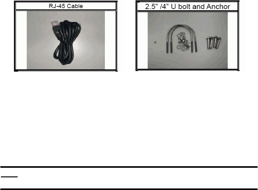
● Waterproof (IP67) RJ-45 Cable (30M) * 1
● Waterproof (IP66) RF Cable (1M) * 1
● Power Over Ethernet Kit * 1
● Ground Wire * 1
● 2.5” /4” U bolts * 2 and Anchor * 4
● RJ-45 Cable (1.5M) * 1
5
Hardware Installation
Once you check off everything from the package, you can start to install the
ODU. You can mount to a pipe, a pole or to the side of a building. The steps
are showed in the following:
1. You must mount the ODU into the bracket first.
Note: ALL the 4 screws had been tightened onto the ODU and
Bracket
2. You can use the 2 or 4 inches U bolt to mount on the pipe, depending on the
radius of the pipe. (Wall mounting is referred to Wall Mounting Figure) The
two U bolts must be mounted tightly. Be aware of not over-tighten the U bolt.
6
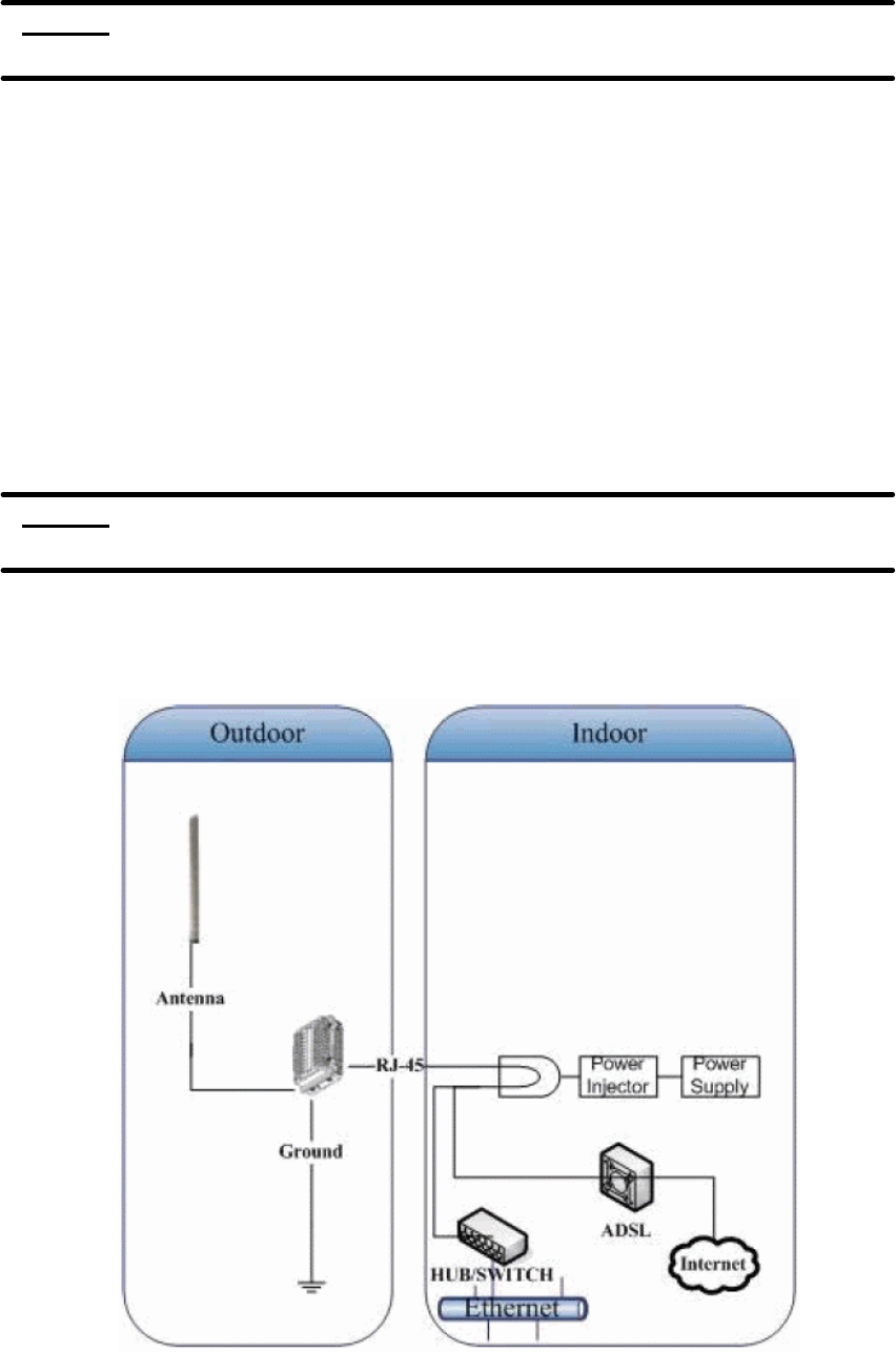
3. After checking the ODU is mounted well, you can connect the following two
cables: the Waterproof RJ-45 network cable to “P+ DATA OUT” port of ODU
and the RF cable to antenna port. Additional waterproof tool, such as
waterproof tape, is recommended to use to enhance the waterproof function.
It is suggested to have a lightening protector between antenna and antenna
port. Connect the ground wire as the figure of “ODU ground wire
connection.”
4. Plug the other end of the waterproof RJ-45 cable to the PoE device. The
PoE device is guaranteed only in indoor environment.
7
Caution: DON’T plug the power cord into PoE device before you finish install
the antenna and Ground wire to ensure the safety.
If the RJ-45 cable’s length is not long enough to connect to your network
device for indoor parts installation, you can extend the cable length.
However, make sure the maximum length of the RJ-45 cable is shorter than
100M (about 109 yards) for normal operation under IEEE 802.3 standards.
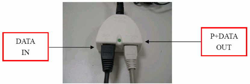
When you plug the regular RJ-45 cable into the PoE device, you should use
the regular RJ-45 cable to plug into the “DATA IN” of “Power Over Ethernet Kit”
to connect to hub/switch or use the crosslink RJ-45 cable (Not included in the
Packing List) to connect with user’s PC.
The waterproof RJ-45 cable must be connected to the “P+DATA OUT” port.
Caution: Be careful! Don’t plug the two cables inversely. It will damage the
devices!
We recommend you refer to the following illustration as a guideline for
hardware installation.
8
Ch 2. First Time Configuration
Before Start to Configure
There are two ways to configure the device, one is through web-browser,
and the other is through Secure Shell CLI interface. To access the
configuration interfaces, make sure you are using a computer connected to
the same network as the device. The default IP address of the device is
192.168.2.254, and the subnet-mask is 255.255.255.0.
The device has three operation modes (Router/Bridge/WISP). In bridge
mode, also known as AP Client, you can access the device by both WLAN
(Wireless Local Area Network) and wired LAN. And in router/WISP modes,
the device can be accessed by both WLAN and WAN. The default IP
addresses for the device are 192.168.2.254(for LAN), 172.1.1.1(for WAN),
so you need to make sure the IP address of your PC is in the same subnet
as the device, such as 192.168.2.X (for LAN), 172.1.1.X (for WAN).
Please note that the DHCP server inside the device is default to up and
running. Do not have multiple DHCP servers in your network environment,
otherwise it will cause abnormal situation.
We also provide an auto-discovery tool which is for finding out the IP of the
device. In case, you’ve forgot the IP of the device or the IP of the device has
been changed, you can use the tool to find out the IP of the device even your
PC is not in the same subnet as the device is.
Knowing the Network Application
ZW-2000 can act as the following roles, and it supports WDS (Wireless
Distribution System) function.
l Access Point
l WDS (Wireless Repeater)
l Bridge/Router
l WISP
l AP Client
The device provides 3 different operation modes and the wireless radio of device
can act as AP/Client/WDS. The operation mode is about the communication
mechanism between the wired Ethernet NIC and wireless NIC, the following is the
9
types of operation mode.
Router
The wired Ethernet (WAN) port is used to connect with ADSL/Cable modem and
the wireless NIC is used for your private WLAN. The NAT is existed between the 2
NIC and all the wireless clients share the same public IP address through the WAN
port to ISP. The default IP configuration for WAN port is static IP. You can access
the web server of device through the default WAN IP address 172.1.1.1 and modify
the setting base on your ISP requirement.
Bridge
The wired Ethernet and wireless NIC are bridged together. Once the mode is
selected, all the WAN related functions will be disabled.
WISP (Wireless ISP)
This mode can let you access the AP of your wireless ISP and share the same public
IP address form your ISP to the PCs connecting with the wired Ethernet port of the
device. To use this mode, first you must set the wireless radio to be client mode and
connect to the AP of your ISP then you can configure the WAN IP configuration to
meet your ISP requirement.
The wireless radio of the device acts as the following roles.
AP (Access Point)
The wireless radio of device serves as communications “hub” for wireless clients
and provides a connection to a wired LAN.
AP Client
This mode provides the capability to connect with the other AP using
infrastructure/Ad-hoc networking types. With bridge operation mode, you can
directly connect the wired Ethernet port to your PC and the device becomes a
wireless adapter. And with WISP operation mode, you can connect the wired
Ethernet port to a hub/switch and all the PCs connecting with hub/switch can share
the same public IP address from your ISP.
WDS (Wireless Distribution System)
This mode serves as a wireless repeater; the device forwards the packets to another
AP with WDS function. When this mode is selected, all the wireless clients can’t
survey and connect to the device. The device only allows the WDS connection.
WDS+AP
This mode combines WDS plus AP modes, it not only allows WDS connections but
10
also the wireless clients can survey and connect to the device.
The following table shows the supporting combination of operation and wireless
radio modes.
Bridge Router WISP
AP V V X
WDS V V X
Client V X V
AP+WDS V V X
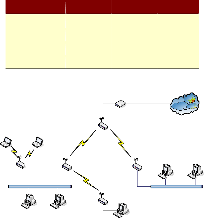
Hereafter are some topologies of network application for your reference.
Bridge Mode
With
AP
Bridge Mode
With
WDS + AP
Bridge Mode
Router Mode
With
WDS + AP
WISP Mode
Internet
Broadband
Modem
11
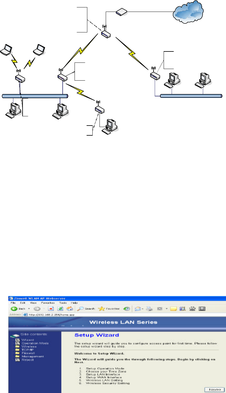
Examples of Configuration
192.168.2.x
192.168.3.x192.168.3.x
192.168.2.x
192.168.2.x 192.168.2.x
192.168.2.x
DEV 1
LAN 192.168.2.254/24
WAN PPPoE connection
Wireless Channel: 11 / SSID: ZPlus -G120-DEV 1
MAC Address of WLAN(BSSID) 000000042728
DHCP Server enabled (IP Pool 192.168.2.1~253)
DEV 2
LAN 192.168.2.202/24
Wireless Channel: 11 / SSID: ZPlus -G120-DEV 2
MAC Address of WLAN (BSSID) 000000042692
DEV 5
LAN 192.168.2.205/24
DEV 4
LAN 192.168.3.1/24
WAN Dynamic IP address
DHCP Server enabled (IP pool 192.168.3.2~254)
DEV 3
LAN 192.168.2.203/24
Channel : 5
SSID : ZPlus -G120-DEV 3
Internet
Broadband
Modem
WISP
Bridge Mode
Bridge Mode
With
AP
Bridge Mode
With
WDS + AP
Router Mode
With
WDS + AP
This example demonstrates how to set up a network with different device
configurations. There are 2 DHCP servers (DEV1/DEV4) in the network to control
the IP configuration of 2 domains (192.168.2.x/192.168.3.x). Once the setting is
done, all the PCs can visit Internet through DEV1.
We assume all the devices keep the factory default setting. To make sure that user
can continuing press the rest button for more than 5 seconds to restore the factory
default setting.
The following descriptions show the steps to configure DEV1 to DEV5.
Configure DEV1:
1. Connect the ADSL modem to Ethernet port of device using Ethernet cable.
2. Access the web server (http://192.168.2.254) of device from the wireless
station.
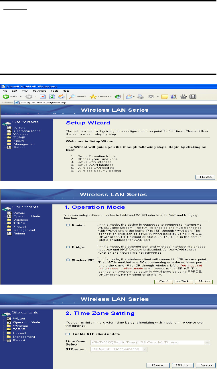
3. Use Wizard page to setup device.
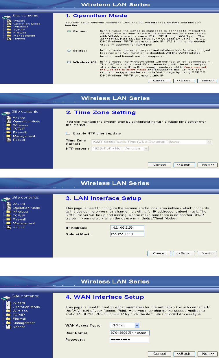
12
4. Press “Next>>” button then set the “Operation Mode” to “Router” mode.
5. Press “Next>>” button then disable “Time Zone” function.
6. Press “Next>>” button then set the IP address of LAN interface.
7. Press “Next>>” button then select the “PPPoE” for “WAN Access Type” and
fill in the “User Name” and “Password” fields.
13
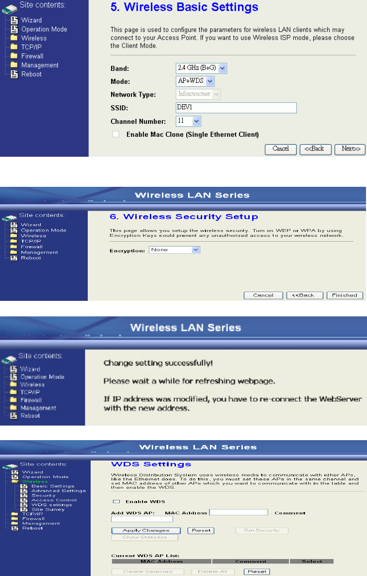
8. Press “Next>>” button then select the “AP+WDS” for “mode” and change the
SSID to “DEV1”.
9. Press “Next>>” button then select “None” for “Encryption” then press
“Finished” button.
10. Wait for refreshing web page.
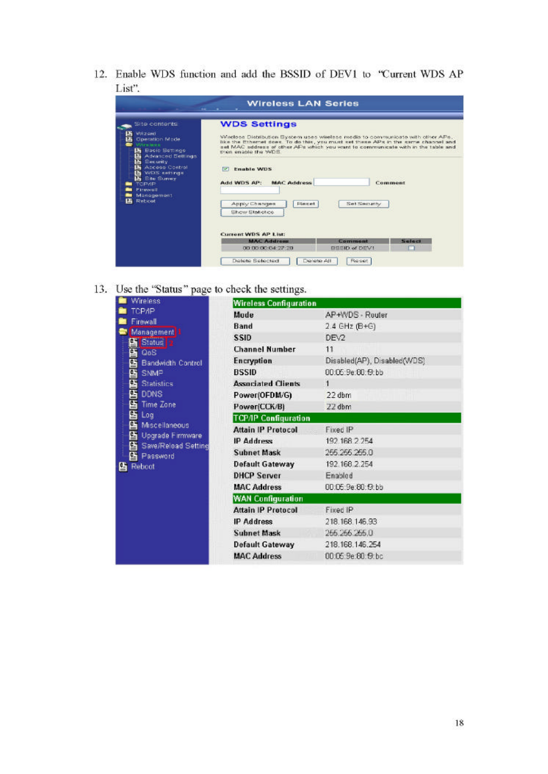
11. Use “WDS Settings” page to configure WDS.
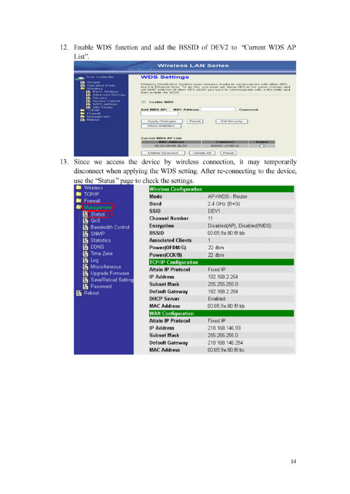
15
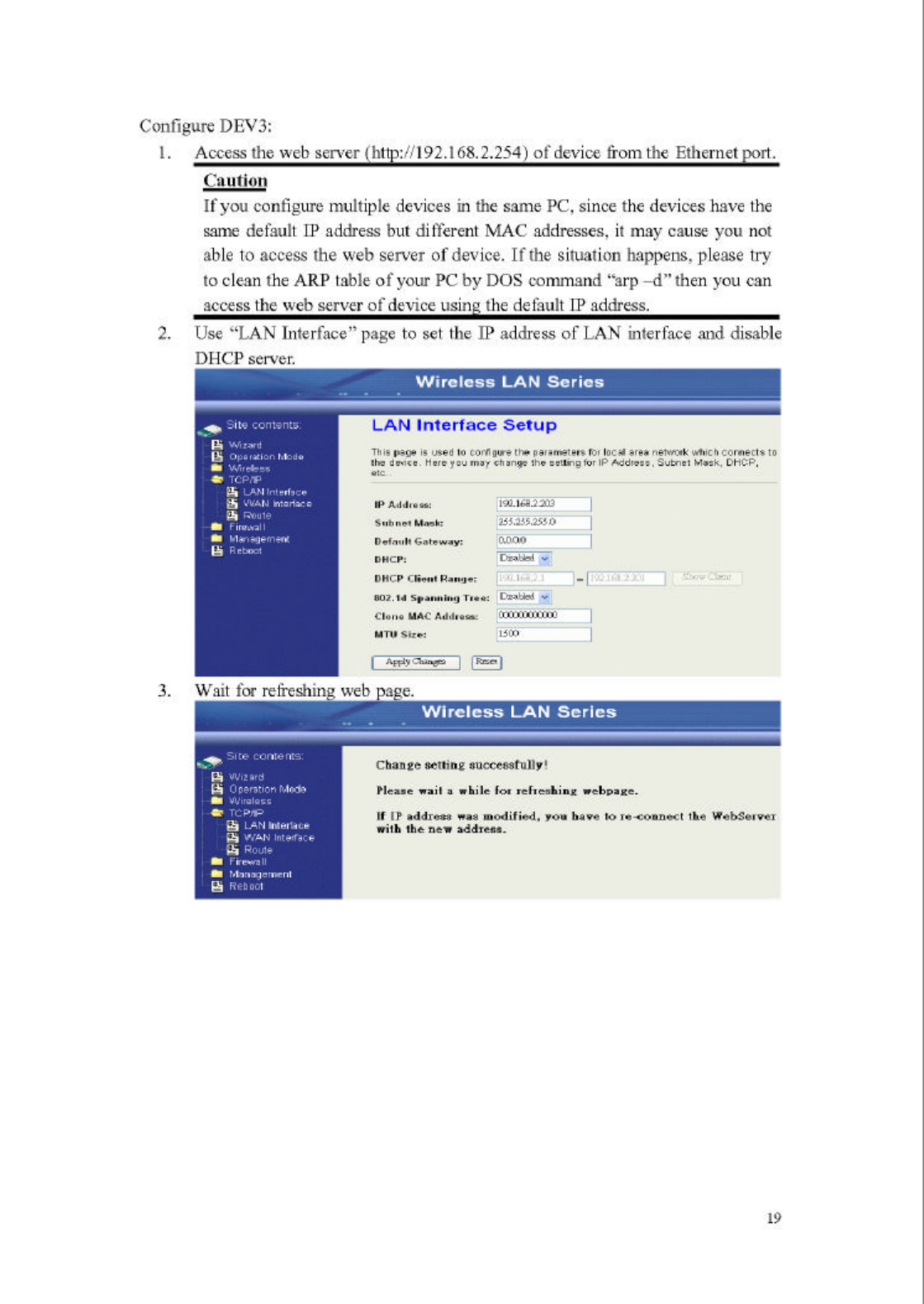
Configure DEV2:
1. Access the web server (http://192.168.2.254) of device from the Ethernet port.
Caution
If you configure multiple devices in the same PC, since the devices
have the same default IP address but different MAC addresses, it may
cause you not able to access the web server of device. If the situation
happens, please try to clean the ARP table of your PC by DOS
command “arp –d” then you can access the web server of device
using the default IP address.
2. Use Wizard page to setup device.
3. Press “Next>>” button then set the “Operation Mode” to “Bridge” mode.
4. Press “Next>>” button then disable “Time Zone” function.
16
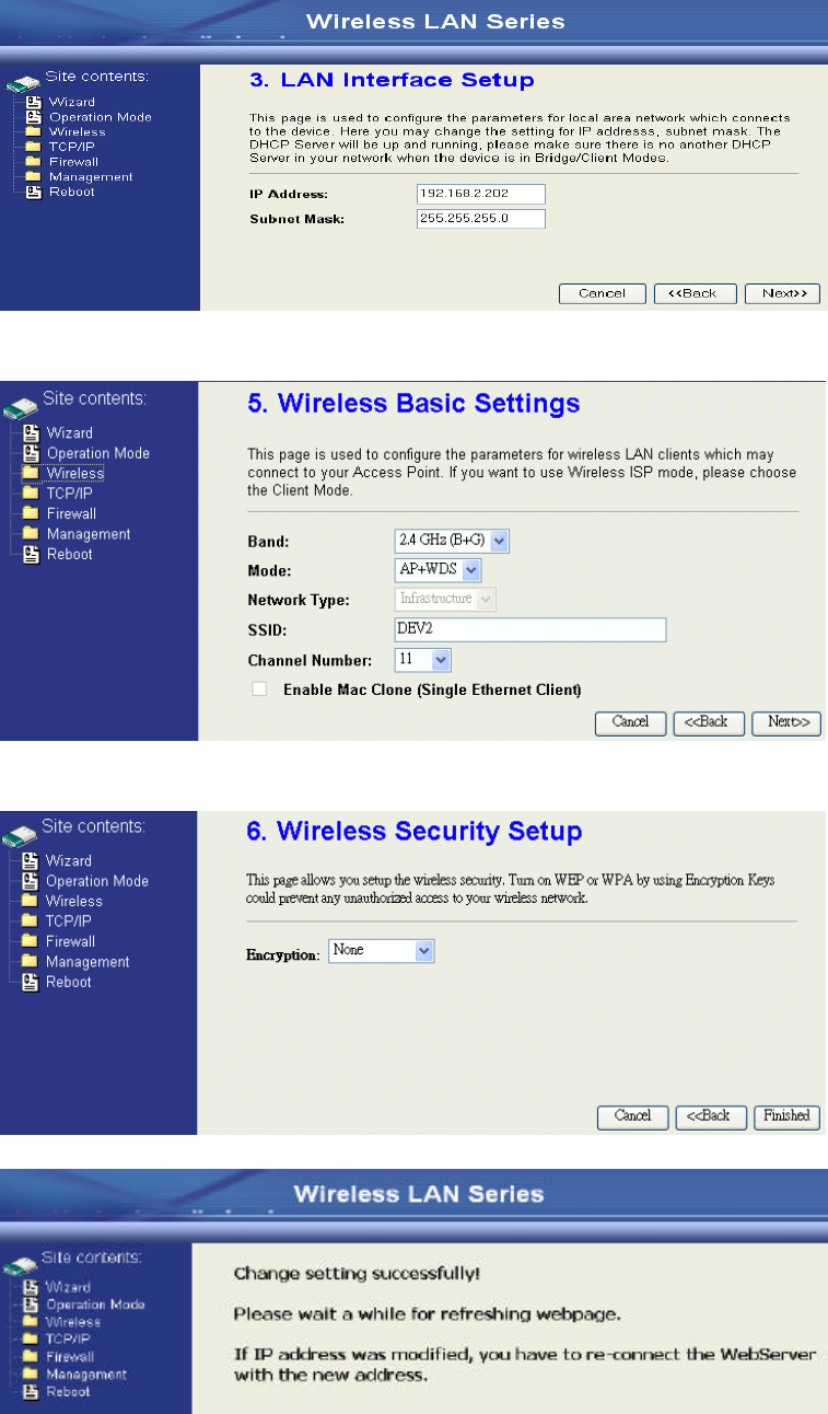
5. Press “Next>>” button then set the IP address of LAN interface.
6. Press “Next>>” button then select the “AP+WDS” for “mode” and change the
SSID to “DEV2”.
7. Press “Next>>” button then select “None” for “Encryption” then press
“Finished” button.
8. Wait for refreshing web page.
17
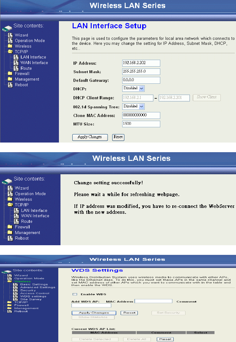
9. Access the web server by new IP address “192.168.2.202” then use “LAN
Interface” page to disable DHCP Server.
10. Wait for refreshing web page.
11. Use “WDS Settings” page to configure WDS.