Zinwell ZW-2000-22 2.4G OutDoor Device User Manual ZW 2000 Manual 0727
Zinwell Corporation 2.4G OutDoor Device ZW 2000 Manual 0727
Zinwell >
Contents
- 1. Users Manual 1
- 2. Users Manual 2
- 3. Users Manual 3
Users Manual 3
35
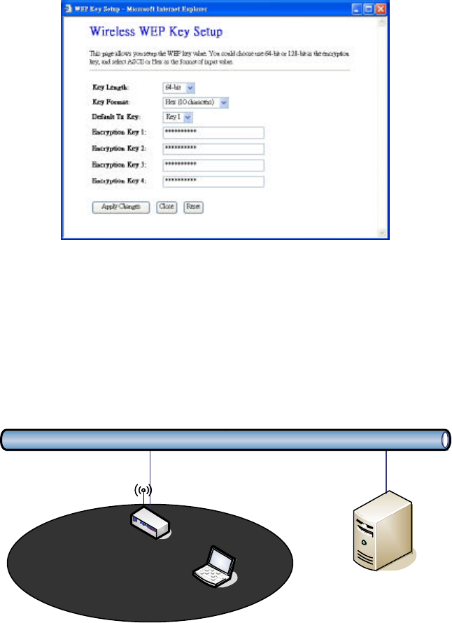
When you decide to use the WEP encryption to secure your WLAN, please
refer to the following setting of the WEP encryption:
l 64-bit WEP Encryption:64-bit WEP keys are as same as the encryption
method of 40-bit WEP. You can input 10 hexadecimal digits (0~9, a~f or
A~F) or 5 ACSII chars.
l 128-bit WEP Encryption :128-bit WEP keys are as same as the
encryption method of 104-bit WEP. You can input 26 hexadecimal digits
(0~9, a~f or A~F) or 10 ACSII chars.
l The Default Tx Key field decides which of the four keys you want to use in
your WLAN environment.
WEP Encryption with 802.1x Setting
The device supports external RADIUS Server that can secure networks
against unauthorized access. If you use the WEP encryption, you can also use
the RADIUS server to check the admission of the users. By this way every
user must use a valid account before accessing the Wireless LAN and
requires a RADIUS or other authentication server on the network. An example
is shown as following.
Ethernet
RADIUS Server
Wireless Station
ZWA-G120
You should choose WEP 64 or 128 bit encryption to fit with your network
environment first. Then add user accounts and the target device to the
RADIUS server. In the device , you need to specify the IP address、Password
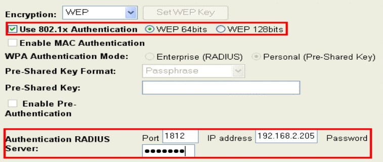
36
(Shared Secret) and Port number of the target RADIUS server.
WPA Encryption Setting
WPA feature provides a high level of assurance for end-users and
administrators that their data will remain private and access to their network
restricted to authorized users. You can choose the WPA encryption and select
the Authentication Mode.
WPA Authentication Mode
This device supports two WPA modes. For personal user, you can use the
Pre-shared Key to enhance your security setting. This mode requires only an
access point and client station that supports WPA-PSK. For Enterprise,
authentication is achieved via WPA RADIUS Server. You need a RADIUS or
other authentication server on the network.
l Enterprise (RADIUS):
When WPA Authentication mode is Enterprise (RADIUS), you have to add
user accounts and the target device to the RADIUS Server. In the device ,
you need to specify the IP address、Password (Shared Secret) and Port
number of the target RADIUS server.
l Pre-Share Key:
This mode requires only an access point and client station that supports
WPA-PSK. The WPA-PSK settings include Key Format, Length and Value.
They must be as same as each wireless client in your wireless network.
When Key format is Passphrase, the key value should have 8~63 ACSII
chars. When Key format is Hex, the key value should have 64 hexadecimal
digits (0~9, a~f or A~F).
37
Configuring as WLAN Client Adapter
This device can be configured as a wireless Ethernet adapter. In this mode,
the device can connect to the other wireless stations (Ad-Hoc network type)
or Access Point (Infrastructure network type) and you don’t need to install
any driver.
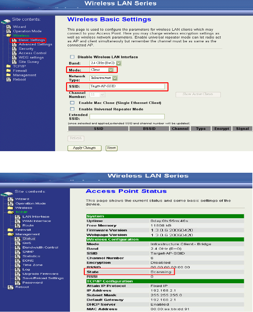
Quick start to configure
Step 1. In “Basic Settings” page, change the Mode to “Client” mode. And key in the
SSID of the AP you want to connect then press “Apply Changes” button to
apply the change.
Step 2. Check the status of connection in “Status” web page
2
1
3
38
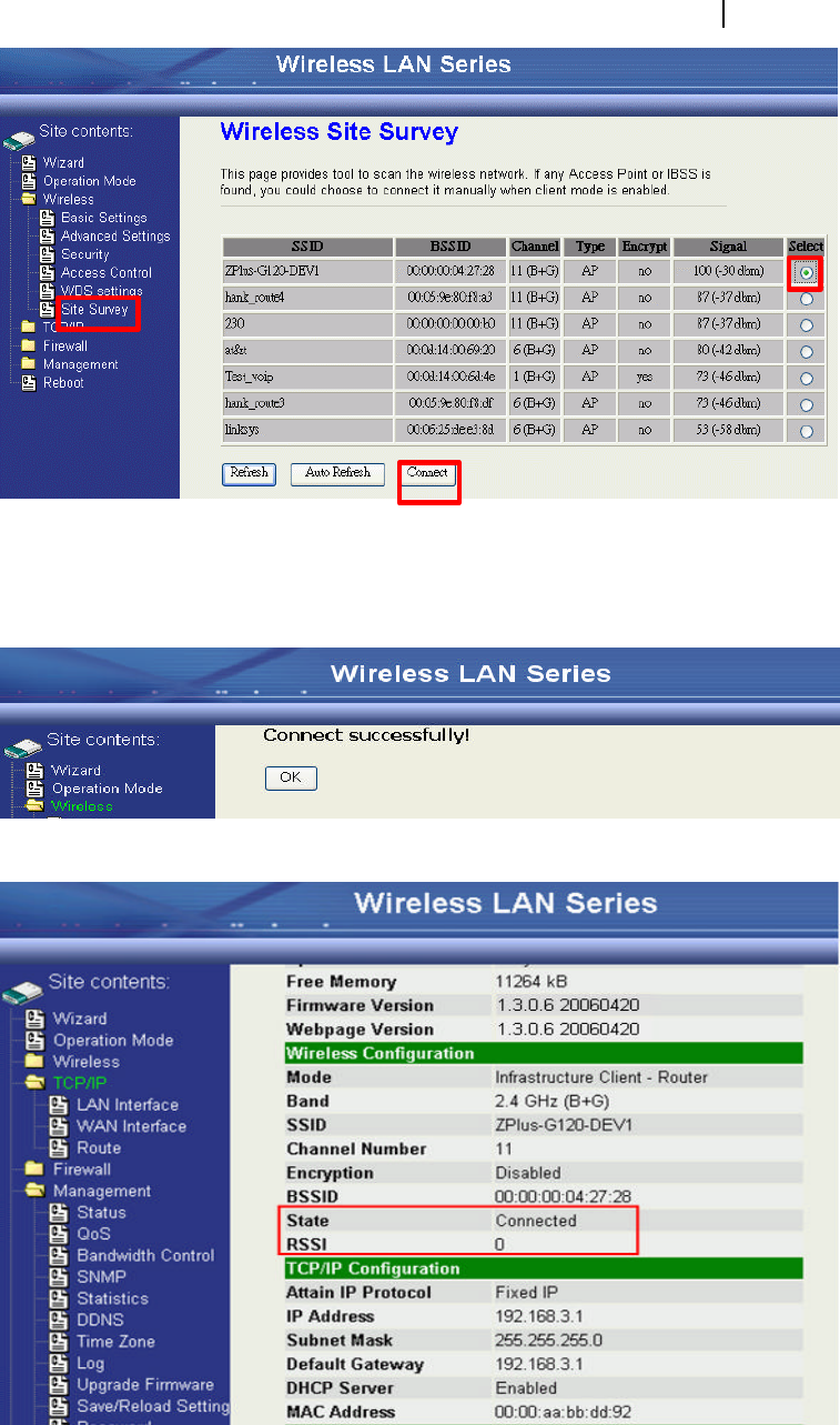
The alternative way to configure as following:
Step 1. In “Wireless Site Survey” page, select one of the SSIDs you want to
connect and then press “Connect” button to establish the link.
Step 2. If the linking is established successfully. It will show the message
“C onnect successfully”. Then press “OK”.
Step 3. Then you can check the linking information in “Status” page.
1
2
3

39
Note :
If the available network requires authentication and data encryption, you need
to setup the authentication and encryption before step1 and all the settings
must be as same as the Access Point or Station. About the detail
authentication and data encryption settings, please refer the security section.
Authentication Type
In client mode, the device also supports two Authentication Types “Open
system” and “Shared Key”. Although the default setting is “Auto”, not every
Access Points can support “Auto” mode. If the authentication type on the
Access Point is knew by user, we suggest to set the authentication type as
same as the Access Point.
Data Encryption
In client mode, the device supports WEP and WPA Personal/Enterprise
except WPA2 mixed mode data encryption. About the detail data encryption
settings, please refer the security section.
40
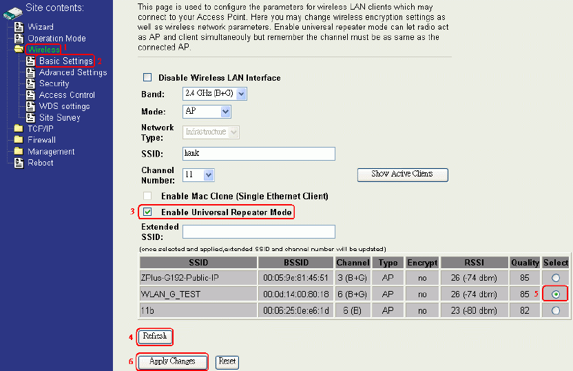
Configuring Universal Repeater
This device can be configured as a Repeater. In this mode, the device can
extend available wireless range of other AP let user can link the network that
they want, Also the device working as AP and Repeater same time.
Following two ways describe how to make Universal Repeater effective.
1. Enable Universal Repeater Mode and then select a SSID in the Table that
you want. Final click Apply Changes button to take effective. (Click
Refresh button to make table renew)
Note: Under AP、WDS and AP+WDS mode, The Universal Repeater can take
effective.
41
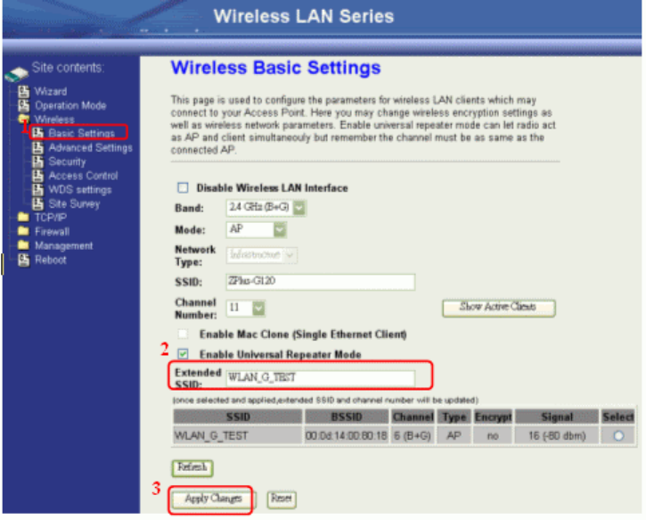
2. Enter specific SSID in the Extended SSID field and then click Apply
Changes button to take effective.
42
Ch 3. Configuring WDS
Wireless Distribution System (WDS) uses wireless media to communicate
with the other devices, like the Ethernet does. This function allows one or
more remote LANs connect with the local LAN. To do this, you must set
these devices in the same channel and set MAC address of other devices
you want to communicate with in the WDS AP List and then enable the
WDS.
When you decide to use the WDS to extend your WLAN, please refer the
following instructions for configuration.
l The bridging devices by WDS must use the same radio channel.
l When the WDS function is enabled, all wireless stations can’t connect
the device.
l If your network topology has a loop, you need to enable the 802.1d
Spanning Tree function.
l You don’t need to add all MAC address of devices existed in your
network to WDS AP List. WDS AP List only needs to specify the MAC
address of devices you need to directly connect to.
l The bandwidth of device is limited, to add more bridging devices will
split the more bandwidth to every bridging device.
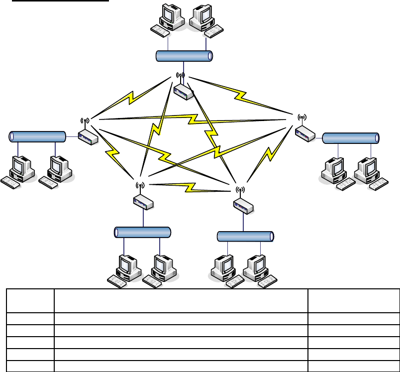
WDS network topology
In this section, we will demonstrate the WDS network topologies and WDS
AP List configuration. You can setup the four kinds of network topologies:
bus, star, ring and mesh.
In this case, there are five devices with WDS enabled: WDS1, WDS2,
WDS3, WDS4 and WDS5.
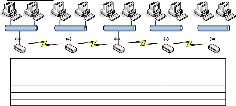
Bus topology:
LAN1LAN2LAN3LAN4LAN5
WDS #1 WDS #4WDS #3WDS #2 WDS #5
Device Entries of WDS AP List Spanning Tree
Protocol Required
WDS1 The MAC Address of WDS2 No
WDS2 The MAC Addresses of WDS1 and WDS3 No
WDS3 The MAC Addresses of WDS2 and WDS4 No
WDS4 The MAC Addresses of WDS3 and WDS5 No
WDS5 The MAC Address of WDS4 No
43
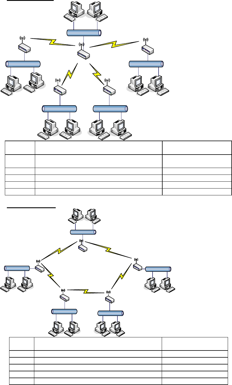
Star topology:
LAN3LAN 4
LAN 1
LAN 2LAN 5
WDS #5 WDS #2
WDS #3WDS #4
WDS #1
Device Entries of WDS AP List Spanning Tree
Protocol Required
WDS1 The MAC Addresses of WDS2, WDS3, WDS4
and WDS5 No
WDS2 The MAC Address of WDS1 No
WDS3 The MAC Address of WDS1 No
WDS4 The MAC Address of WDS1 No
WDS5 The MAC Address of WDS1 No
Ring topology:
LAN3
LAN 4
LAN 1
LAN 2
LAN 5
WDS #5 WDS #2
WDS #3
WDS #4
WDS #1
Device
Entries of WDS AP List Spanning Tree
Protocol Required
WDS1
The MAC Addresses of WDS2 and WDS5 Yes
WDS2
The MAC Addresses of WDS1 and WDS3 Yes
WDS3
The MAC Addresses of WDS2 and WDS4 Yes
WDS4
The MAC Addresses of WDS3 and WDS5 Yes
WDS5
The MAC Addresses of WDS4 and WDS1 Yes
44
Mesh topology:
LAN3
LAN 4
LAN 1
LAN 2
LAN 5
WDS #5 WDS #2
WDS #3
WDS #4
WDS #1
Device Entries of WDS AP List Spanning Tree
Protocol Required
WDS1 The MAC Addresses of WDS2, WDS3, WDS4 and WDS5 Yes
WDS2 The MAC Addresses of WDS1, WDS3, WDS4 and WDS5 Yes
WDS3 The MAC Addresses of WDS1, WDS2, WDS4 and WDS5 Yes
WDS4 The MAC Addresses of WDS1, WDS2, WDS3 and WDS5 Yes
WDS5 The MAC Addresses of WDS1, WDS2, WDS3 and WDS4 Yes
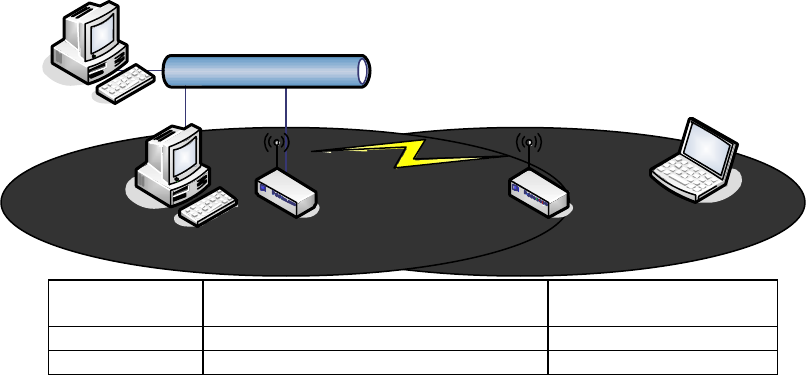
WDS Application
Wireless Repeater
Wireless Repeater can be used to increase the coverage area of another
device (Parent AP). Between the Parent AP and the Wireless Repeater,
wireless stations can move among the coverage areas of both devices.
When you decide to use the WDS as a Repeater, please refer the following
instructions for configuration.
l In AP mode, enable the WDS function.
l You must set these connected devices with the same radio channel and
SSID.
l Choose “WDS+AP” mode.
l Using the bus or star network topology.
45
Ethernet
Wireless station
AP Repeater
Description Entries of WDS AP List Spanning Tree
Protocol Required
Access Point The MAC Address of Repeater Yes
Repeater The MAC Address of Access Point Yes
Wireless Bridge
Wireless Bridge can establish a wireless connection between two or more
Wired LANs. When you decide to use the WDS as a Wireless Bridge, please
refer the following instructions for configuration.
l In AP mode, enable the WDS function.
l You must set these connected devices with the same radio channel, but
you may use different SSID.
l Choose “WDS” mode for only wireless backbone extension purpose.
l You can use any network topology, please refer the WDS topology
section.
46
Ch 4. Advanced Configurations
Configuring LAN to WAN Firewall
Filtering function is used to block or permit packets from LAN to WAN. The
device supports three kinds of filter Port Filtering, IP Filtering and MAC
Filtering. All the entries in current filter table are used to restrict or allow
certain types of packets from your local network to through the device. Use
of such filters can be helpful in securing or restricting your local network.
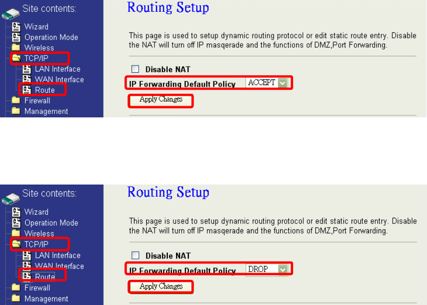
Denied or Allowed list depends on your IP forwarding default policy in Route
page. The IP forwarding default policy is “ACCEPT”.
If you want block some application from LAN to WAN, you can go to Route
page to select “ACCEPT” for IP Forwarding Default Policy.
If you want permit some application from LAN to WAN, you can go to Route
page to select “DROP” for IP Forwarding Default Policy.
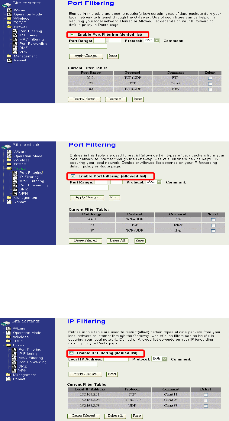
Port Filtering
When you enable the Port Filtering function, you can specify a single port
or port ranges in current filter table. If you select ACCEPT for the IP
forwarding default policy, once the source port of outgoing packets match
the port definition or within the port ranges in the table, the firewall will
block those packets form LAN to WAN.
1
23
4
1
2
3
4
47
If you select DROP for the IP forwarding default policy, once the source
port of outgoing packets match the port definition or within the port ranges
in the table, the firewall will allow those packets form LAN to WAN.
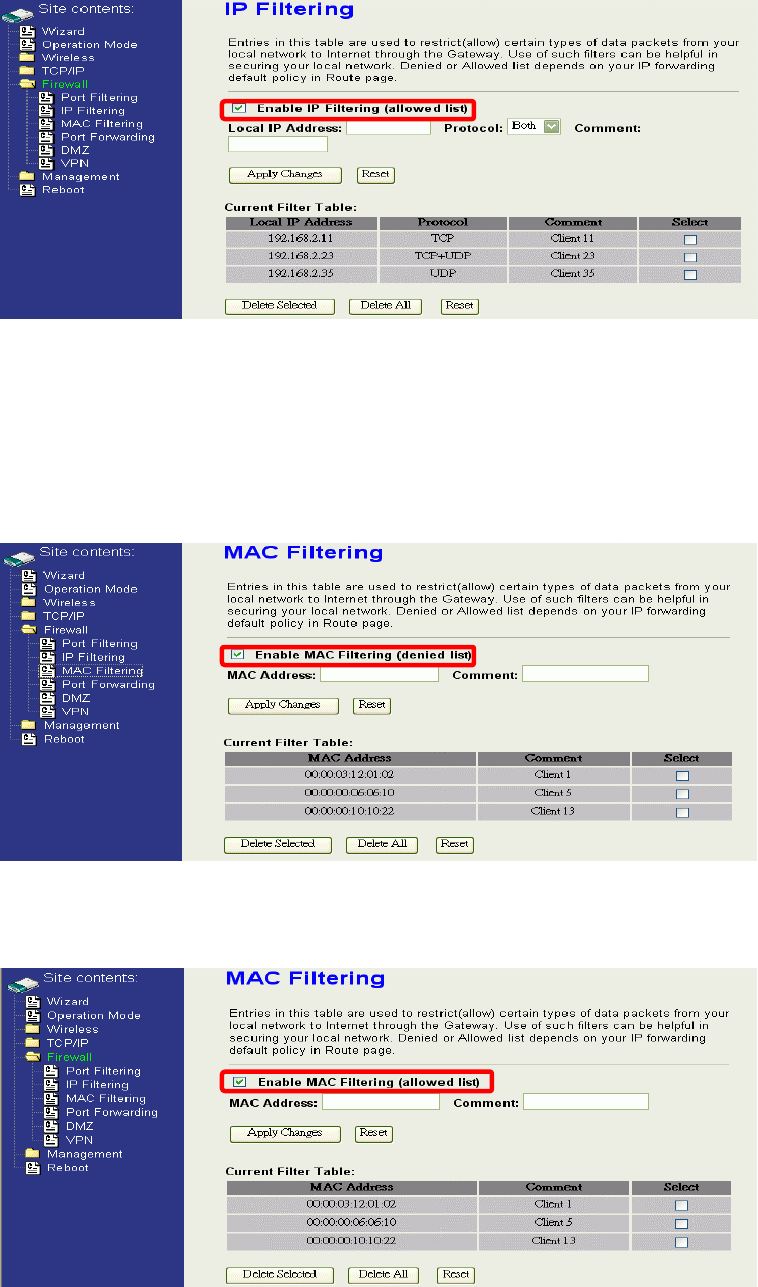
IP Filtering
When you enable the IP Filtering function, you can specify local IP
Addresses in current filter table. If you select ACCEPT for the IP
forwarding default policy, once the source IP address of outgoing packets
match the IP address definition in the table, the firewall will block those
packets form LAN to WAN.
48
If you select DROP for the IP forwarding default policy, once the source IP
address of outgoing packets match the IP address definition in the table,
the firewall will allow those packets form LAN to WAN.
MAC Filtering
When you enable the MAC Filtering function, you can specify the MAC
Addresses in current filter table. If you select ACCEPT for the IP
forwarding default policy, once the source MAC Address of outgoing
packets match the MAC Address definition in the table, the firewall will
block those packets form LAN to WAN.
If you select DROP for the IP forwarding default policy, once the source
MAC Address of outgoing packets match the MAC Address definition in
the table, the firewall will allow those packets form LAN to WAN.
49
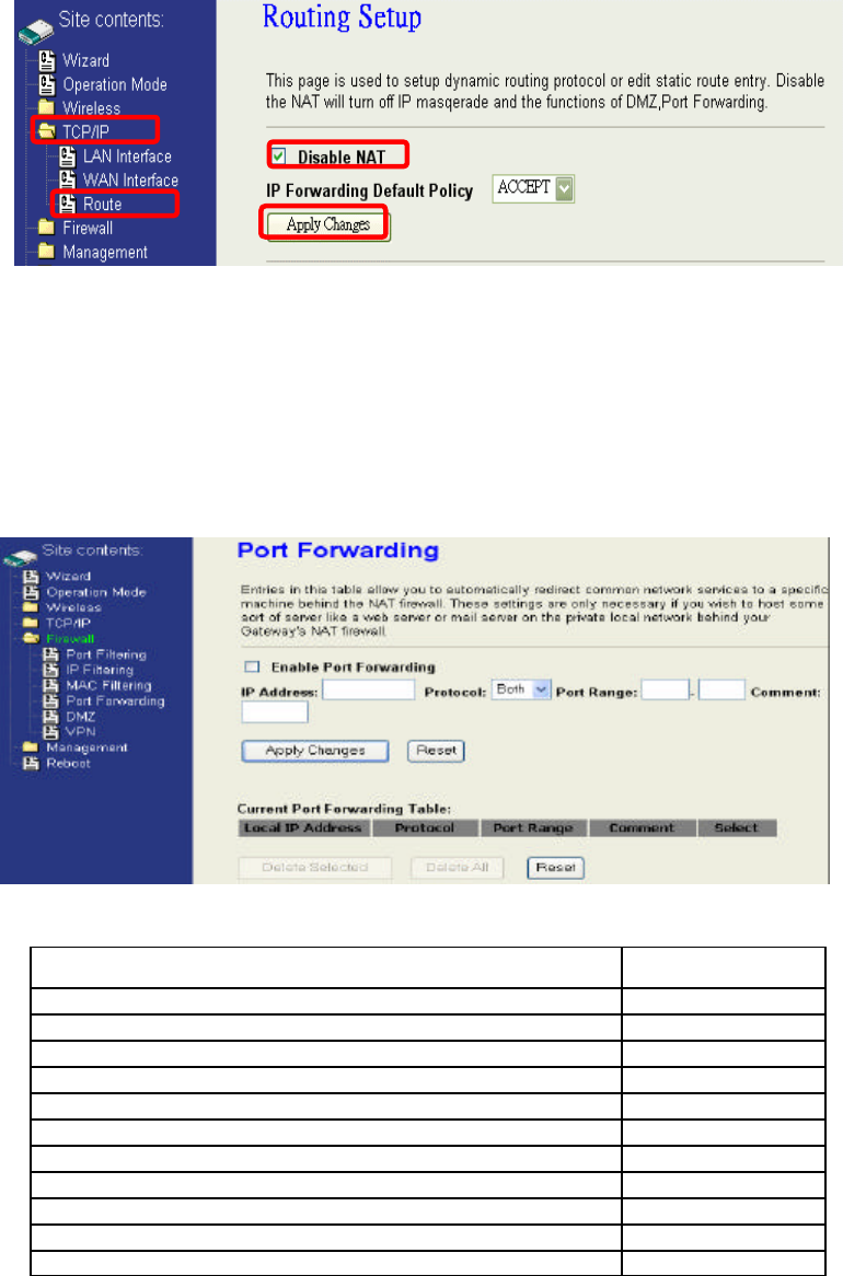
NAT (Network Address Translation)
NAT is the translation between public IP address and private IP address. While
NAT is enabling, you can use port forwarding or DMZ to redirect your common
network services. If you want to disable NAT, you can go to Management-Route
page to disable it and the functions of DMZ, Port Forwarding will be disabled.
Configuring Port Forwarding (Virtual Server)
This function allows you to automatically redirect common network services
to a specific machine behind the NAT firewall. These settings are only
necessary if you wish to host some sort of server like a web server or mail
server on the private local network behind the device's NAT firewall.
The most often used port numbers are shown in the following table.
Services Port Number
ECHO 7
FTP (File Transfer Protocol) 21
Telnet 23
SMTP (Simple Mail Transfer Protocol) 25
DNS (Domain Name System) 53
Finger 79
HTTP (Hyper Text Transfer Protocol) 80
POP3 (Post Protocol) 110
NNTP (Network News Transport Protocol) 119
SNMP (Simple Network Management Protocol) 161
SNMP trap 162
1
2
3
4
50
SIP (Session Initiation Protocol) 5060
PPTP (Point-to-Point Tunneling Protocol) 1723
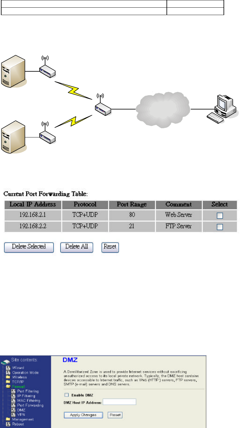
Multiple Servers behind NAT Example:
In this case, there are two PCs in the local network accessible for outside
users.
Internet
Device with Router Mode enabled
WLAN IP Address:192.168.2.254
Web Server
IP Address:192.168.2.1
Port:80
FTP Server
IP Address:192.168.2.2
Port:21
User
AP
AP Client #2
AP Client #1
Configuring DMZ
A Demilitarized Zone is used to provide Internet services without
sacrificing unauthorized access to its local private network. Typically, the
DMZ host contains devices accessible to Internet traffic, such as Web
(HTTP) servers, FTP servers, SMTP (e-mail) servers and DNS servers.
So that all inbound packets will be redirected to the computer you set. It
also is useful while you run some applications (ex. Internet game) that use
uncertain incoming ports.
51
Enable DMZ: Enable the “Enable DMZ”, and then click “Apply Changes” button to
save the changes.
DMZ Host IP Address:
Input the IP Address of the computer that you want to expose to
Internet.
Internet
Device with Router Mode enabled
DNS Host
AP Client
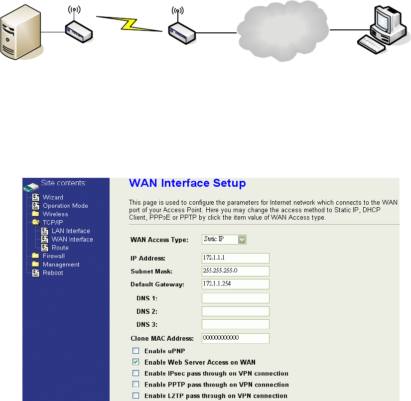
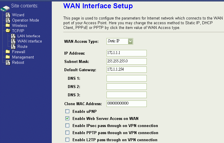
Configuring WAN Interface
The device supports four kinds of IP configuration for WAN interface,
including Static IP, DHCP Client, PPPoE and PPTP. You can select one of
the WAN Access Types depend on your ISP required. The default WAN
Access Type is “Static IP”.
Static IP
You can get the IP configuration data of Static-IP from your ISP. And you
will need to fill the fields of IP address, subnet mask, gateway address,
and one of the DNS addresses.
52
IP Address: The Internet Protocol (IP) address of WAN interface provided by your
ISP or MIS. The address will be your network identifier besides your
local network.
Subnet Mask: The number used to identify the IP subnet network, indicating whether
the IP address can be recognized on the LAN or if it must be reached
through a gateway.
Default Gateway: The IP address of Default Gateway provided by your ISP or MIS.
Default Gateway is the intermediate network device that has knowledge
of the network IDs of the other networks in the Wide Area Network, so it
can forward the packets to other gateways until they are delivered to the
one connected to the specified destination.
DNS 1~3: The IP addresses of DNS provided by your ISP.
DNS (Domain Name Server) is used to map domain names to IP
addresses. DNS maintain central lists of domain name/IP addresses and
map the domain names in your Internet requests to other servers on the
Internet until the specified web site is found.
Clone MAC
Address: Clone device MAC address to the specify MAC address required by your
ISP
Enable uPnP: Enable uPnP, this function allows the device to be found and configured
automatically by the system. (Ex. Window XP)
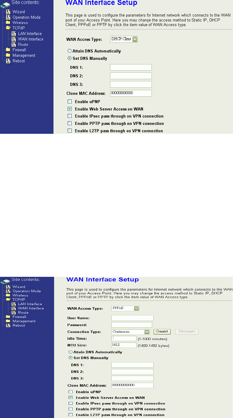
DHCP Client (Dynamic IP)
All IP configuration data besides DNS will obtain from the DHCP server
when DHCP-Client WAN Access Type is selected.
53
DNS1~3: The IP addresses of DNS provided by your ISP.
DNS (Domain Name Server) is used to map domain names to IP
addresses. DNS maintain central lists of domain name/IP
addresses and map the domain names in your Internet requests
to other servers on the Internet until the specified web site is
found.
Clone MAC
Address: Clone device MAC address to the specify MAC address required
by your ISP
Enable uPnP: Enable uPnP, this function allows the device to be found and
configured automatically by the system. (Ex. Window XP)
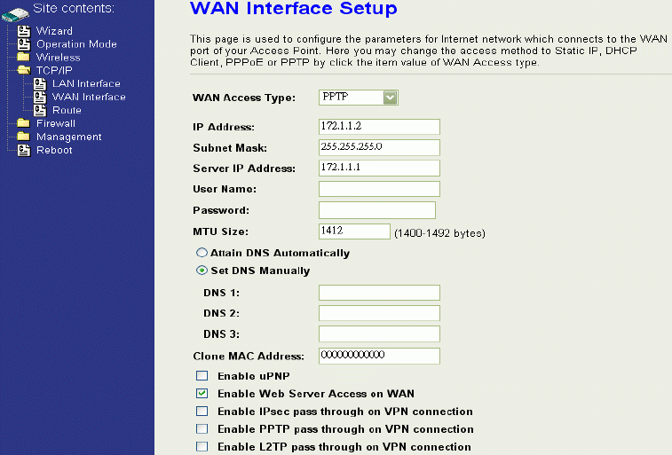
PPPoE
When the PPPoE (Point to Point Protocol over Ethernet) WAN Access
Type is selected, you must fill the fields of User Name, Password provided
by your ISP. The IP configuration will be done when the device
successfully authenticates with your ISP.
54
User Name: The account provided by your ISP
Password: The password for your account.
Connect Type: “Continuous “ : connect to ISP permanently
“Manual” : Manual connect/disconnect to ISP
“On-Demand”: Automatically connect to ISP when user needs to
access the Internet.
Idle Time: The number of inactivity minutes to disconnect from ISP. This
setting is only available when “Connect on Demand” connection
type is selected.
MTU Size: Maximum Transmission Unit, 1412 is the default setting; you may
need to change the MTU for optimal performance with your specific
ISP.
DNS1~3: The IP addresses of DNS provided by your ISP.
DNS (Domain Name Server) is used to map domain names to IP
addresses. DNS maintain central lists of domain name/IP
addresses and map the domain names in your Internet requests to
other servers on the Internet until the specified web site is found.
Clone MAC
Address: Clone device MAC address to the specify MAC address required
by your ISP.
Enable UPnP: Enable UPnP, this function allows the device to be found and
configured automatically by the system. (Ex. Window XP)
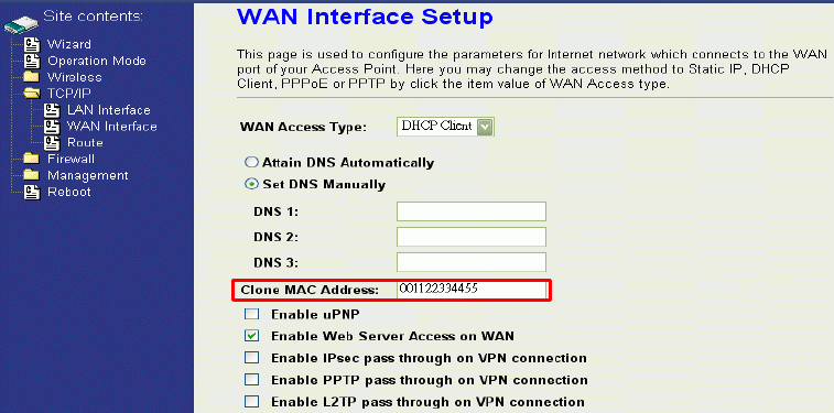
PPTP
Point to Point Tunneling Protocol (PPTP) is a service that applies to
connections in Europe only.
55
IP Address: The Internet Protocol (IP) address of WAN interface provided by
your ISP or MIS. The address will be your network identifier
besides your local network.
Subnet Mask: The number used to identify the IP subnet network, indicating
whether the IP address can be recognized on the LAN or if it
must be reached through a gateway.
Server IP Address:
(Default Gateway)
The IP address of PPTP server
User Name: The account provided by your ISP
Password: The password of your account
MTU Size: Maximum Transmission Unit, 1412 is the default setting, you
may need to change the MTU for optimal performance with your
specific ISP.
DNS1~3: The IP addresses of DNS provided by your ISP.
DNS (Domain Name Server) is used to map domain names to IP
addresses. DNS maintain central lists of domain name/IP
addresses and map the domain names in your Internet requests
to other servers on the Internet until the specified web site is
found.
Clone MAC Address: Clone device MAC address to the specify MAC address required
by your ISP.
Enable uPnP: Enable uPnP, this function allows the device to be found and
configured automatically by the system. (Ex. Window XP)
Configuring Clone MAC Address
The device provides MAC address clone feature to fit the requirement of
some ISP need to specify the client MAC address.
Physical WAN interface MAC Address clone
1. Clone MAC address for DHCP Client WAN access type
2. Clone MAC address for Static IP WAN access type
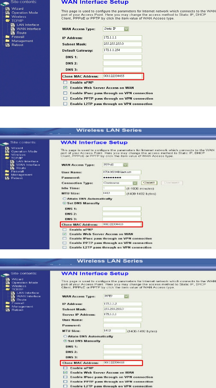
56
3. Clone MAC address for PPPoE WAN access type
4. Clone MAC address for PPTP WAN access type
57
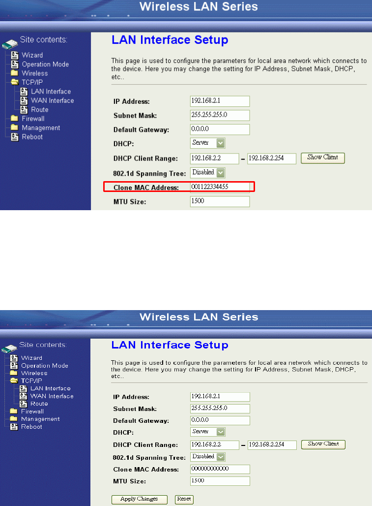
5. Physical LAN interface MAC address clone
Configuring DHCP Server
1. To use the DHCP server inside the device, please make sure there is no other
DHCP server existed in the same network as the device.
2. Enable the DHCP Server option and assign the client range of IP addresses as
following page.
3. When the DHCP server is enabled and also the device router mode is enabled
then the default gateway for all the DHCP client hosts will set to the IP
address of device.
Bandwidth Control
This functionality can control Bandwidth of Up/Downstream
1. Enable Bandwidth Control and then enter Data Rate、Latency and Burst Packet in
the specific field.
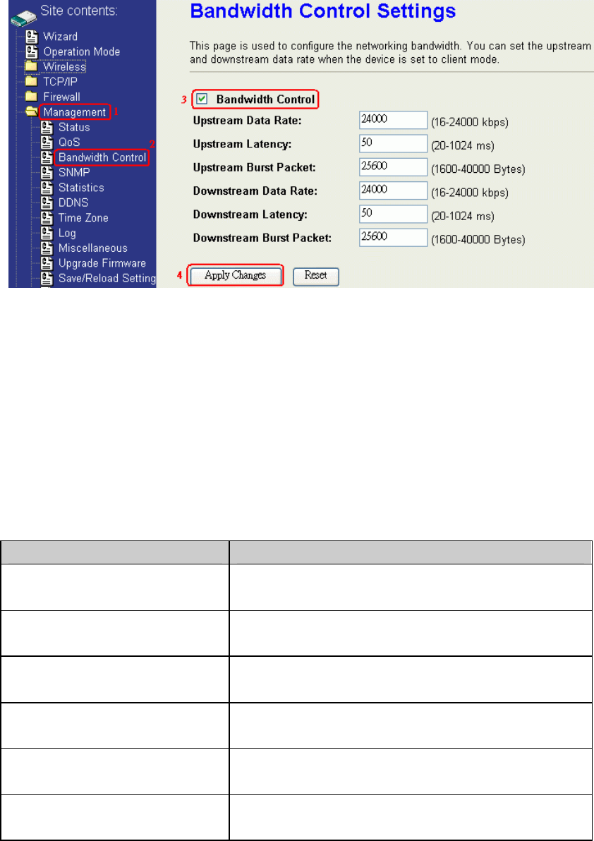
58
Note: Only device on Client mode or WISP mode this functionality can take
effective.
2. Parameter Definition
Label Description
Upstream Data Rate Speed of transmit data that from Ethernet
interface to Wireless interface.
Upstream Latency Similar a waiting time the data queuing-
time.
Upstream Burst Packet Similar a buffer the data will into the buffer
while the data is transmit or receive.
Downstream Data Rate Speed of transmit data that from Wireless
interface to Ethernet interface.
Downstream Latency Similar a waiting time the data queuing-
time.
Downstream Burst Packet Similar a buffer the data will into the buffer
while the data is transmit or receive.
59
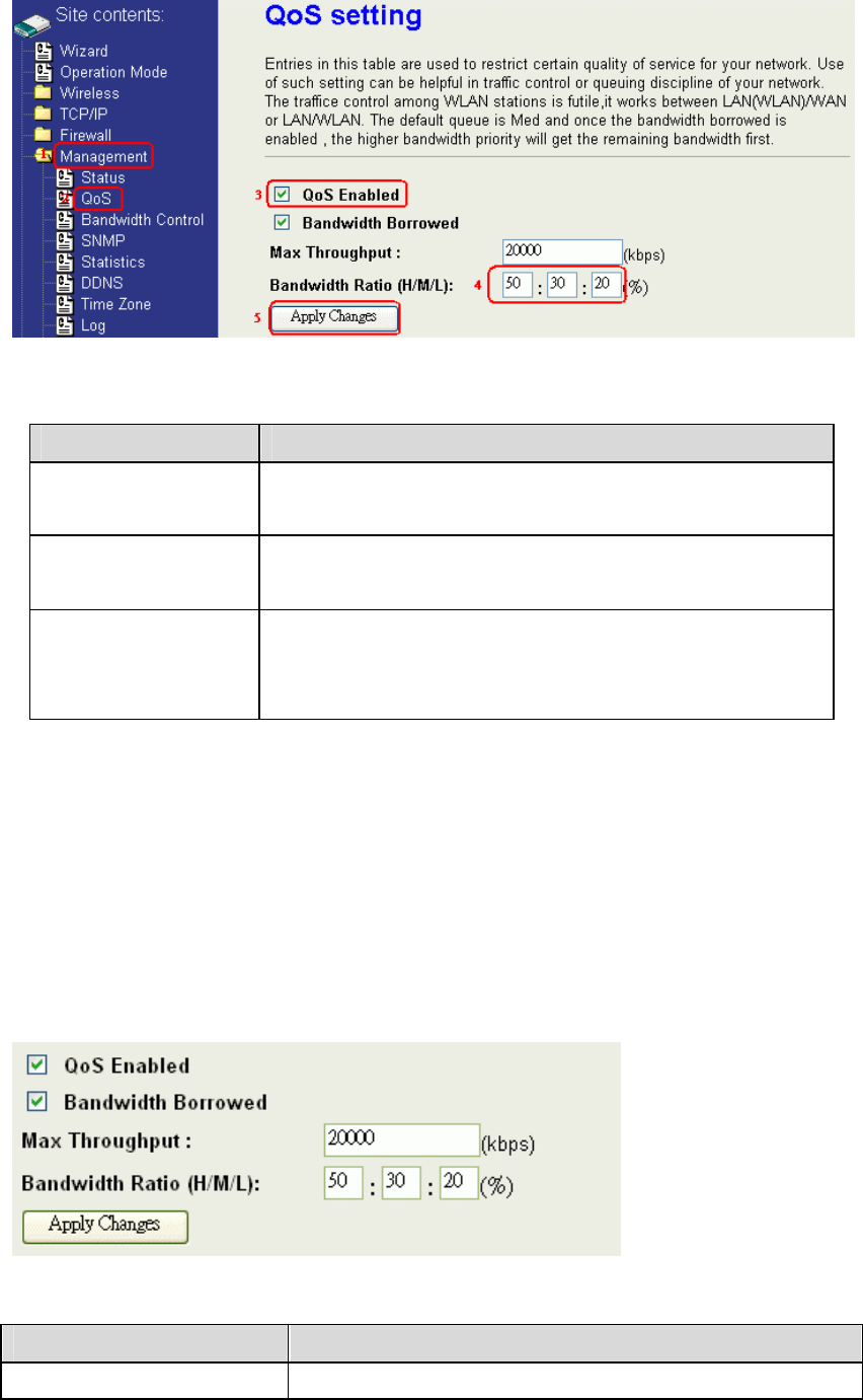
QoS (Quality of Service)
Filter Priority and IP-ToS have not finished yet and also fine tuning.
QoS allows you to specify some rules, to ensure the quality of service in your network.
Such as use Bandwidth Priority concept to allocate bandwidth. This function can be
helpful in shaping and queuing traffic from LAN (WLAN) to WAN or LAN to
WLAN, but not WLAN to WLAN.
Enable the QoS and then fill in Bandwidth Ratio (H/M/L) the device has three
Bandwidth Priorities High, Medium and Low user can allocation Bandwidth to these
and default is High:50%, Medium:30% and Low:20%.
60
The following table describes the priorities that you can apply to bandwidth.
Priority Level Description
High Typically used for voice or video applications that is
especially sensitive to the variations in delay.
Medium Typically used for important traffic that can tolerate
some delay.
Low Typically used for non-critical traffic such as a large
number of transfers but that should not affect other
application.
Click the QoS link under Management to open the QoS Setting page. This page is
divided into three parts: basic settings, QoS rule settings, and current QoS setting
table.
1. Enable QoS and enter Max Throughput (default 20Mbps) 、
Bandwidth Ratio (default H:50%, M:30%, L:20%)
The following table describes the labels in this part.
Label Description
QoS Enabled Select this check box to enable quality of service.

61
Bandwidth Borrowed Select this check box to allow a rule to borrow unused
bandwidth. Bandwidth borrowing is decided by priority
of the rules. Higher priority will get the remaining
bandwidth first.
Max Throughput Enter the value of max throughput in kbps that you want
to allocate for one rule. The value should between 1200
kbps and 24000 kbps.
Bandwidth Ratio (H/M/L) You can specify the ratio of priority in these fields. The
range from 1 to 99. The High priority’s ratio should
higher than Medium priority’s ratio and Medium
priority’s ratio should higher than Low priority’s ratio.
Apply Changes Click this button to save and apply your settings.
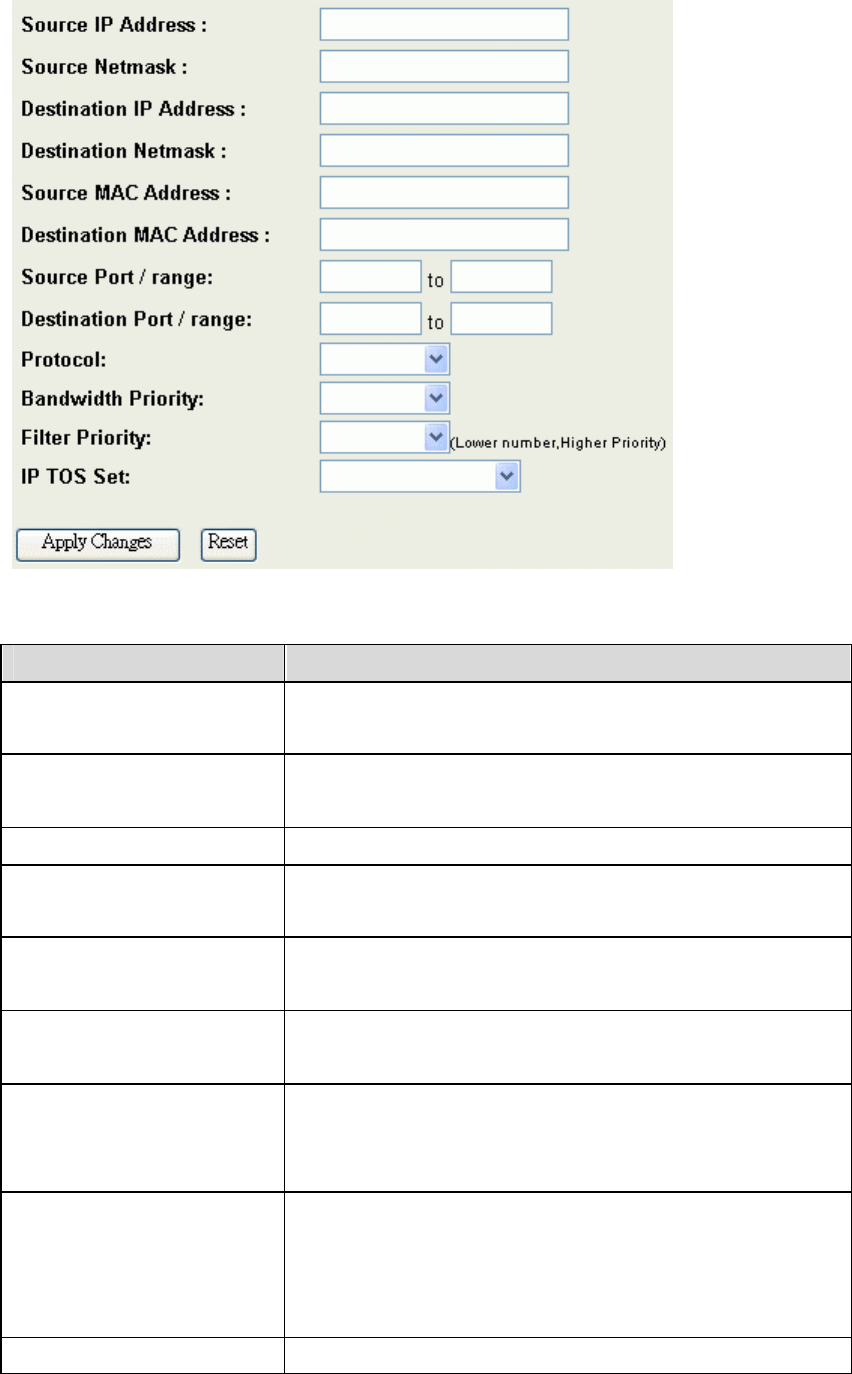
2. QoS Rule settings
62
The following table describes the labels in this part.
Label Description
IP Address Enter source/destination IP Address in dotted decimal
notation.
Netmask Once the source/destination IP Address is entered, the
subnet mask address must be filled in this field.
MAC Address Enter source/destination MAC Address.
Port / range You can enter specific port number or port range of the
source/destination
Protocol Select a protocol from the drop down list box. Choose
TCP/UDP, TCP or UDP.
Bandwidth Priority Select a bandwidth priority from the drop down list box.
Choose Low, Medium or High.
Filter Priority Select a filter priority number from the drop down list
box. Lower number gets higher priority while two
rules have the same bandwidth priority.
IP TOS Match Select an IP type-of-service value from the drop down
list box. Choose Normal Service, Minimize Cost,
Maximize Reliability, Maximize Throughput, or
Minimize Delay.
Apply Changes Click this button to save and apply your settings.
63
Reset Click this button to begin re-input the parameters.
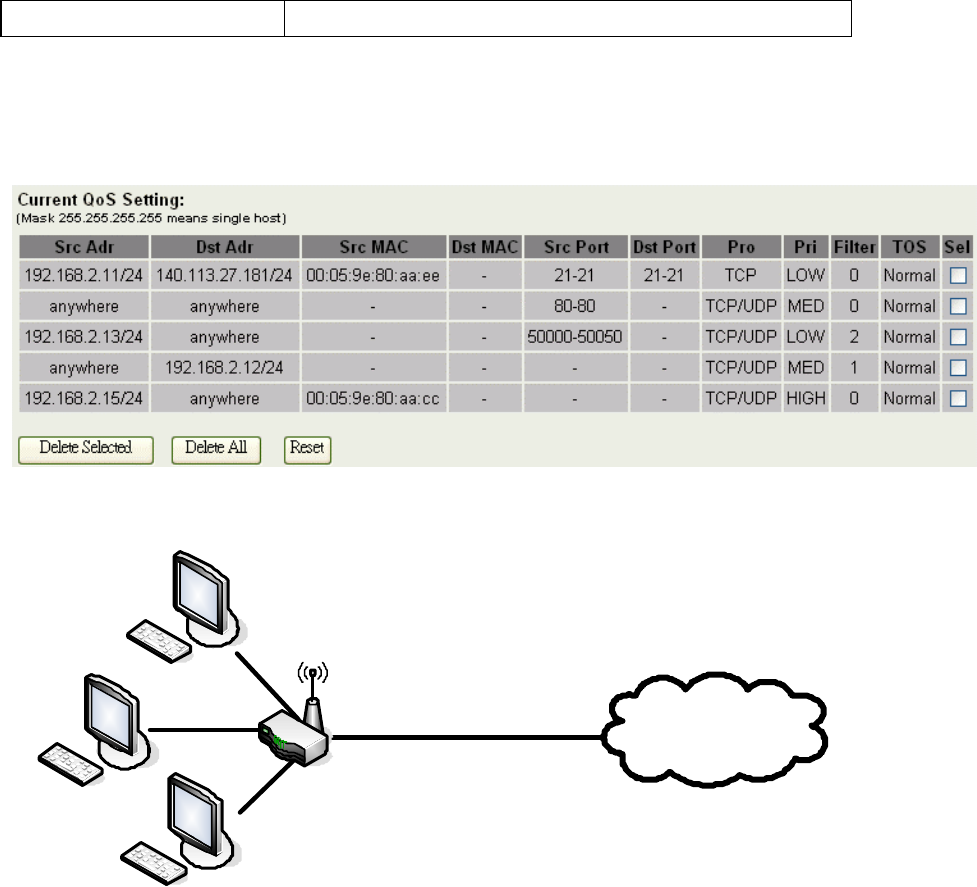
Current QoS setting table
In this part, you can see how many rules have been specified. And you can see the
detail about the rules and manage the rules. This table can input 50 rules at most.
An example for usage
User B
Internet
Zplus-G192
WANLAN
VoIP
FTP
Web
User A
User C
For example, there are three users in your network.
Ÿ User A wants to browse the websites to retrieve information.
Ÿ User B wants to use FTP connection to download a large file.
Ÿ User C wants to use software phone to connect with customer.
The voice is sensitive to the variations in delay; you can set High priority for User C.
The FTP transmission may take a long time; you can set Low priority for User B.
64
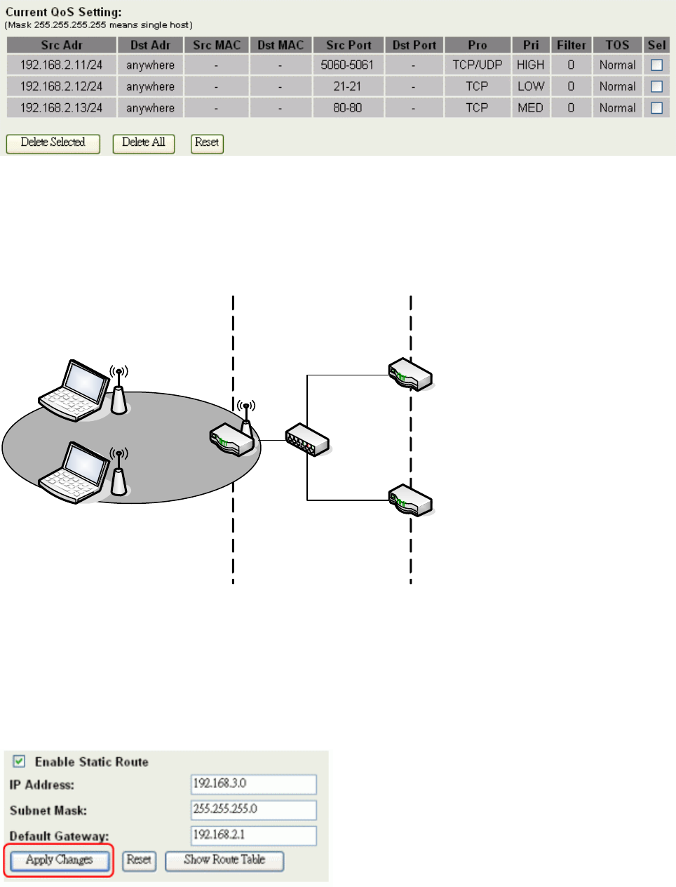
Static Route Setup
User can set the routing information let the Router knows what routing is correct also
it can not learn automatically through other means.
Network 1Network 2
Network 3
Network 4
R1
R2
HUB
For example, if user wants to link the Network 3 and Network 4 separately from
Network 1 that Routing Table configuration as blow:
1. Enable Static Route in Route Setup of TCP/IP page and then enter IP Address of
Network 3、Subnet Mask and IP Address of Router (R1) in Default Gateway field
final click Apply Change button.
65
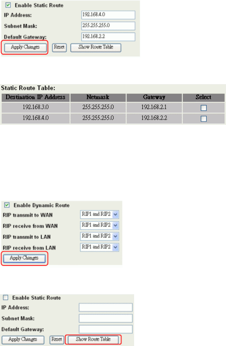
2. Enter IP Address of Network 4、Subnet Mask and IP Address of Router (R2) in
Default Gateway field final click Apply Change button.
3. In Static Route Table there have two routings for Network 3 and Network 4
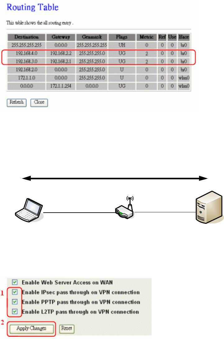
Dynamic Route Setup
The Dynamic Route utilizes RIP1/2 to transmit and receive the route information with
other Routers.
1. Enable Dynamic Route and then select RIP 1、RIP2 or Both to transmit/receive
packets final click Apply Change button.
2. Click Show Route Table button to show Dynamic Route Table.
66
3. In Dynamic Routing Table there have two routings for Network 3 and Network 4
VPN Pass-through
This functionality let the device can Pass-through the VPN packets including PPTP/
L2TP/IPsec VPN Connection.
VPN Server
(VPN Passthrough)
WAN
Laptop 1 VPN Client
VPN Connection
LAN
1. Check the VPN Pass-through in WAN Interface of TCP/IP Page that you want and
then click Apply Changes button.
Using CLI Menu
Start a SSH(Secure Shell) client session to login the device
The SSH server daemon inside device uses well-known TCP port 22.
User must use SSH client utility such like Putty to login the device. The
default password for user “root” is “qwert”, once user login the device
then can change the password by CLI command.
Execute CLI program
67
This program won’t execute automatically when user login the device.
User must manually execute it by typing the case-sensitive command
“cli”. Please note that any modified settings won’t save permanently
until user “Apply Changes to Flash” or reboot it. The new settings
modified by CLI will take effect after rebooting the device.
Menu Tree List
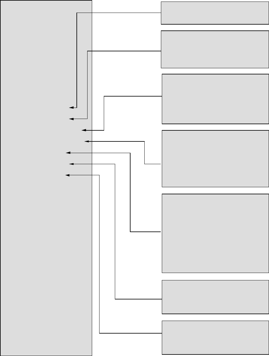
68
A. Operation Mode
B. Wireless Setting
C. TCP/IP-LAN Setting
D. TCP/IP-WAN Setting
E. Route Setting
F. Firewall Setting
G. Management
H. Apply Changes to Flash
I. Reboot to take effect
0. Exit
Wireless Setting
A. Basic Settings
B. Advanced Settings
C. Security Settings
D. Access Control Settings
E. WDS Settings
0. Exit
TCP/IP WAN Settings
A. WAN Type
B. IP Address
C. Subnet Mask
D. Default Gateway
E. DNS1
F. DNS2
G. DNS3
Y. Clone MAC Address
Z. uPNP
0. Exit
Route Settings
-[Dynamic Route]------------------
A. Dynamic Route
B. RIP transmit to WAN
C. RIP receive from WAN
D. RIP transmit to LAN
E. RIP receive from LAN
-[Static Route]---------------------- -
F. Static Route
G. Add Static Route Setting
H. Delete Static Route Setting
I. Delete all Static Route Setting
J. Current Static Route Setting List
-[Route Table]------------------------
K. Show Route Table List
0. Exit
Wireless Basic Settings
A. Access Point Status
B. QoS Settings
C. Bandwidth Control
D. SNMP Settings
E. Password
0. Exit
Firewall Settings
A. Port Filtering
B. IP Filtering
C. MAC Filtering
D. Port Forwarding
E. DMZ
0. Exit
Operation Mode
1: Router
2: Bridge
0: Cancel
TCP/IP-LAN Setting
A. IP Address
B. Subnet Mask
C. Default Gateway
D. DHCP
E. DHCP Client Range
F. 802.1d Spanning Tree
G. Clone MAC Address
H. MTU Size
0. Exit
69
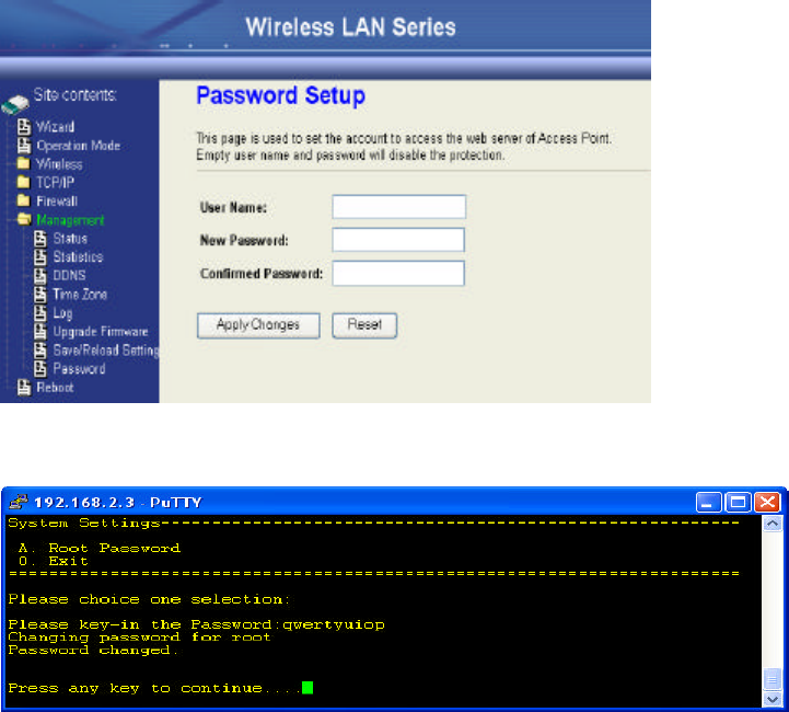
The System Management
Password Protection
Both Web-Browser and SSH configuration interfaces have password
protection.
To disable the Web-Browser password protection just leave the “User
Name” field to blank then click “Apply Changes” button.
To change the password of user “root” for SSH session, please use the
CLI menu item G. System SettingàA. Root Password
70
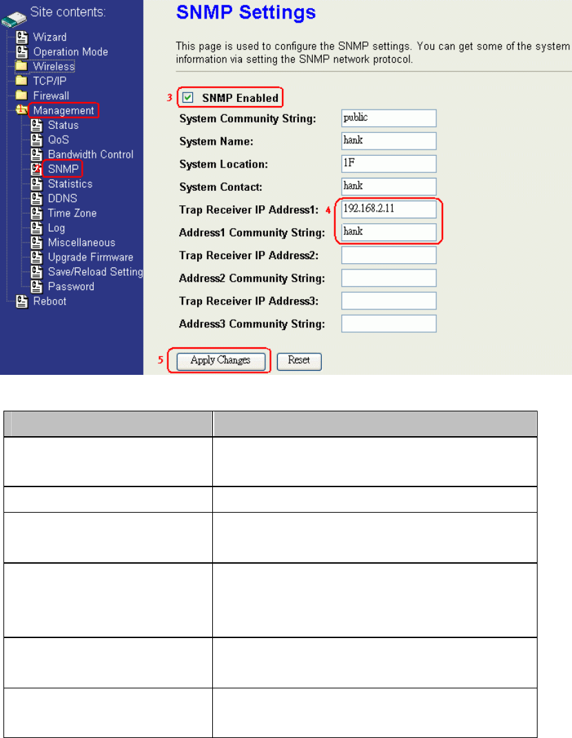
SNMP Agent
This device is compatible with SNMP v1/v2c and provides standard MIB II.
Currently only the “public” community string is available and the modified
settings by SNMP SET request will be lost after rebooting the device.
1. Enable SNMP and then enter IP Address of SNMP Manager in Trap
Receiver IP Address field and Community String in System Community
String field. Final click Apply Changes button.
2. Following Table describes the SNMP configuration parameter
Label Description
System Community String
This is password sent with each trap to the
SNMP Manager.
System Name Type the Name which is name of device.
System Location Type the Location which is location of
device
System Contact Type the Name which is person or group
when the device has problem can find
they.
Trap Receiver IP Address Type the IP Address which is address of
SNMP Manager.
Trap Receiver Community
String
This is password receive with trap from
the device (SNMP Agent).
71
3. SNMP Traps
Traps Description
coldStart(0) The trap from device after reboot the
device
linkDown(2) The trap is sent when any of the links are
down. See the following table.
linkup(3) The trap is sent when any of the links are
UP. See the following table.
authenticationFailure(4) The trap is sent when the device receiving
gets or sets requirement with wrong
community.
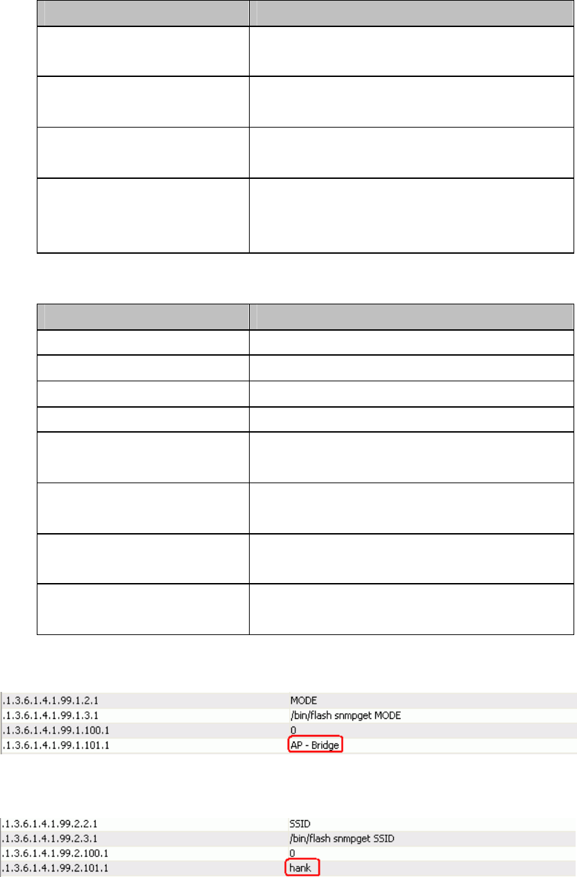
4. Private MIBs
OID Description
1.3.6.1.4.1.99.1 Mode, Operation Mode in device.
1.3.6.1.4.1.99.2 SSID, SSID of the device
1.3.6.1.4.1.99.3 Channel, Channel of the device in WLAN
1.3.6.1.4.1.99.4 Band, 802.11g / 802.11b only
1.3.6.1.4.1.99.5 RSSI, Receive Signal Strength Index
(Support AP and Client RSSI)
1.3.6.1.4.1.99.6 Active_Clients, The number of associate
clients
1.3.6.1.4.1.99.7 Active_Clients_List, Client’s Information
(MAC Address, Data Rate, RSSI…etc)
1.3.6.1.4.1.99.8 Encryption, Encryption type of device in
Wireless Network
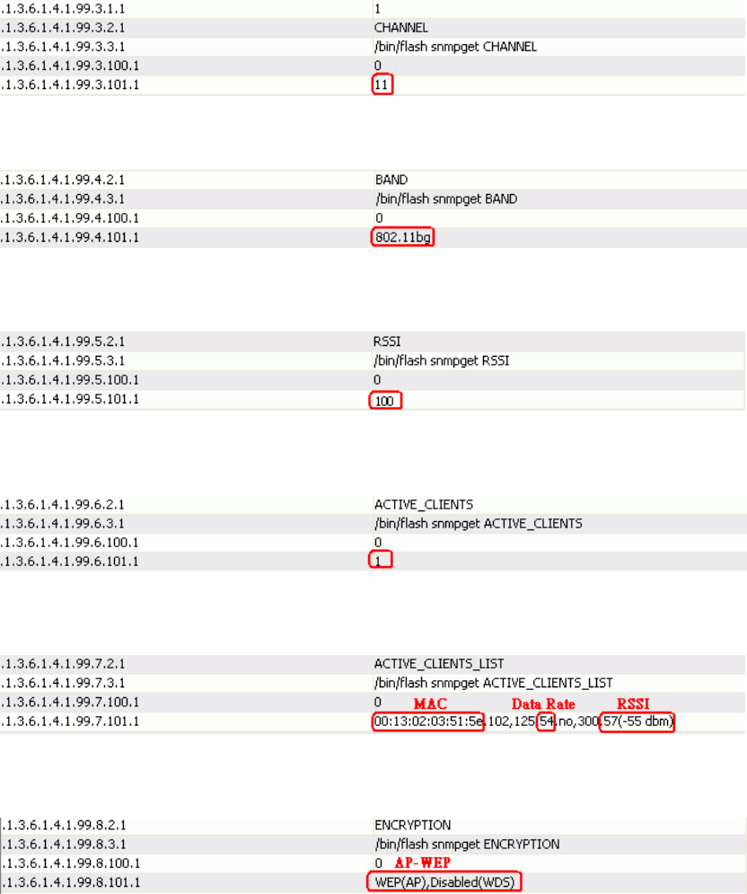
1.3.6.1.4.1.99.1 - Mode
1.3.6.1.4.1.99.2 - SSID
72
1.3.6.1.4.1.99.3 - Channel
1.3.6.1.4.1.99.4 - Band
1.3.6.1.4.1.99.5 - RSSI
1.3.6.1.4.1.99.6 - Active_Clients
1.3.6.1.4.1.99.7 - Active_Clients_List
1.3.6.1.4.1.99.8 - Encryption
73
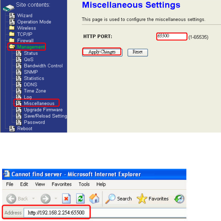
Miscellaneous Settings
The default http port is 80. For internet security, you can change the
device’s http port, to protect this web server from hacker’s attack.
1. Entering the port number you want to change in HTTP PORT field,
then click Apply Changes button.
2. After apply change, you should re-login the web server. Type
http://192.168.2.254:65500/ in URL field.
1
2
3
4

74
Firmware Upgrade
Firmware Types
The firmware for this device is divided into 2 parts, one is web pages
firmware the other is application firmware, and the naming usually are
zw2000webpage.bin and zw2000linux.bin. To upgrade firmware, we
suggest user first upgrade the application firmware then web pages
firmware.
Upgrading Firmware
The Web-Browser upgrading interface is the simplest and safest
way for user, it will check the firmware checksum and signature, and the
wrong firmware won’t be accepted. After upgrading, the device will
reboot and please note that depends on the version of firmware, the
upgrading may cause the device configuration to be restored to the
factory default setting, and the original configuration data will be lost!
To upgrade firmware, just assign the file name with full path then click
“Upload” button as the following page.
Memory Limitation
To make sure the device have enough memory to upload firmware,
the system will check the capacity of free memory, if the device lack of
memory to upload firmware, please temporarily turn-off some functions
then reboot the device to get enough memory for firmware uploading.
Configuration Data Backup & Restore
Rest Setting to Factory Default Value
Since the device is designed for outdoor used, there is no interface
outside the housing to reset the configuration value to the factory
default value. The device provides the Web-Browser interface to rest
the configuration data. After resetting it, the current configuration data
will be lost and restored to factory default value.
Saving & Restoring Configuration Data
75
To save & restore configuration data of device, just assign the target
filename with full path at your local host, then you can backup
configuration data to local host or restore configuration data to the
device.
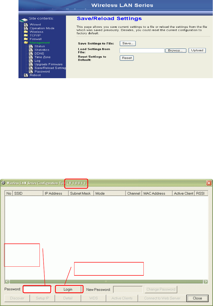
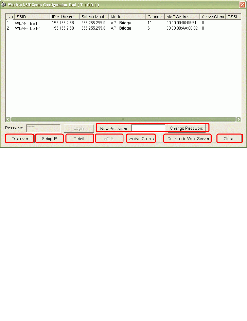
Auto Discovery Tool
User can use this tool to find out how many devices in your local area network. The
name of tool is WirelessConf.exe it in the packing CD.
This tool has password protected. The default password is “qwert”, after login, you
can change the password.
1. Enter
Password
2. Click on Login button
Tool’s Version
76
1. Change Password
You can change password for this tool. Fill the new password in the New
Password field, and then click on Change Password button.
2. Discover
After press this button, you could see there are how many devices in your network.
And you would see the basic information about these devices, such as:
Ÿ SSID
Ÿ IP Address
Ÿ Subnet Mask
Ÿ Operation Mode
Ÿ Channel number
Ÿ MAC Address
Ÿ Active Client: this field shows how many clients associated with the device
Ÿ RSSI: this field shows Received Signal Strength Indication while device is
on AP-Client mode
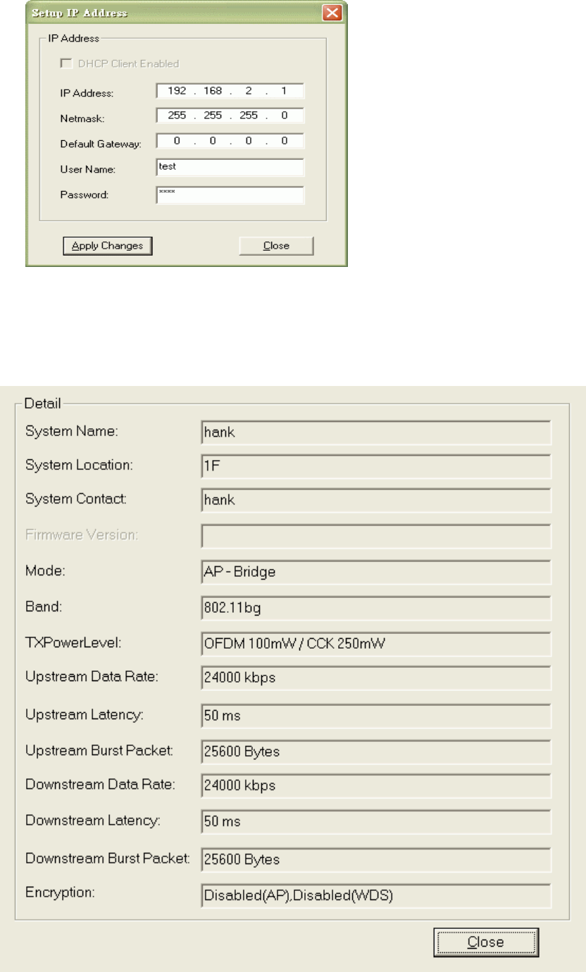
3. Setup IP
After you press the Setup IP button, you would see Setup IP Address window.
You could change device’s IP Address, Netmask, and Default Gateway in this
window. But if the device’s web server needs User Name and Password to login,
you should fill in these two fields and then apply changes.
‚ ƒ „ … † ‡ ˆ
•
77
4. Detail
If you want to see more detailed information, you could press the Detail button,
and then you would see the Detail Information window.
78
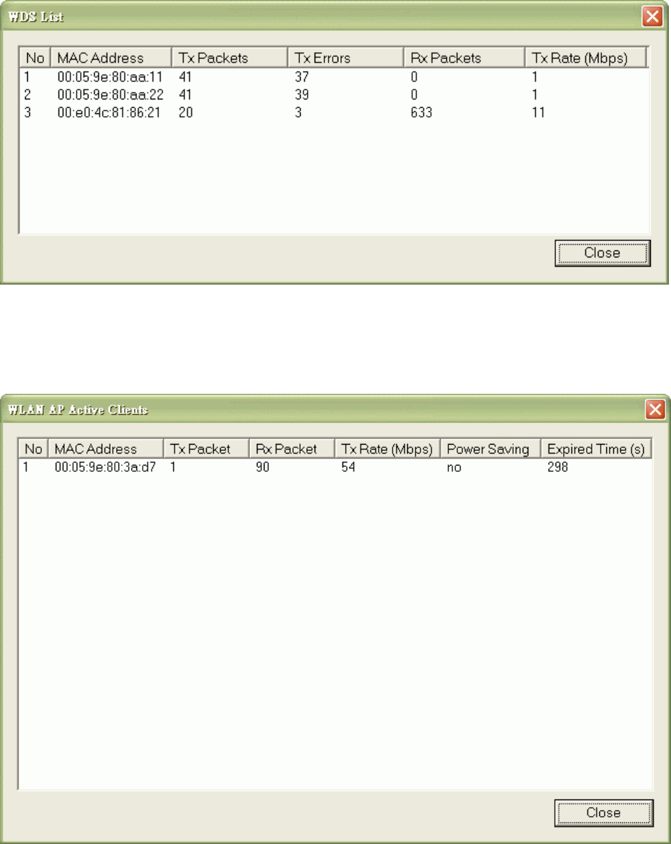
5. WDS
If the device you selected is on WDS mode or AP+WDS mode, you could press
WDS button, and then you would see the WDS List window.
6. Active Clients
After press Active Clients button, you would see WLAN AP Active Clients
window. In this window, you could see client’s information, such as:
79
7. Connect to Web Server
If you want connect to device’s web server, you could press this button, or
double-click on the device.
8. Close
You could press this button to leave this tool.
This equipment has been tested and found to comply with the limits for a class B
digital device, pursuant to part 15 of the FCC rules. These limits are designed to
provide to provide reasonable protection against harmful interference in a residential
installation. This equipment generates, uses and can radiate radio frequency energy
and, if not installed and used in accordance with the installation. , May cause harmful
interference to radio communication. However, there is no guarantee that interference
Will not occur in a particular installation. if this equipment does cause harmful
interference to radio or television reception, which can be determined by turning the
equipment off and on, the user is encouraged to try to correct the interference by one
or more of the following measures:
-Reorient or relocate the receiving antenna
-Increase the separation between the equipment and receiver
-Connect the equipment into an outlet on a circuit different from that to which the
receiver is connected
-Consult the dealer or an experienced radio / TV technician for help
You are cautioned that changes or modifications not expressly approved by the party
responsible for compliance could void your authority to operate the equipment.
1. This transmitter must not be co-located or operating in conjunction with any
other antenna or transmitter.
2. This equipment complies with FCC RF radiation exposure limits set forth for
an uncontrolled environment. This equipment should be installed and operated with a
minimum distance of 20 centimeters between the radiator and your body.
REMARK: This device must be installed by professional.