Zinwell ZW-2200 802.11 a/g WLAN Outdoor AP User Manual ZW 2200 Manual 1220
Zinwell Corporation 802.11 a/g WLAN Outdoor AP ZW 2200 Manual 1220
UserManual.wiki
>
Zinwell
>
ZW-2200 User Manual
>
User Manual 2 of 2
Contents
1.
User Manual 1 of 2
2.
User Manual 2 of 2
User Manual 2 of 2
Navigation menu
Upload a User Manual
Namespaces
Wiki Guide
HTML
PDF
Info
Views
User Manual
Discussion / Help
Navigation
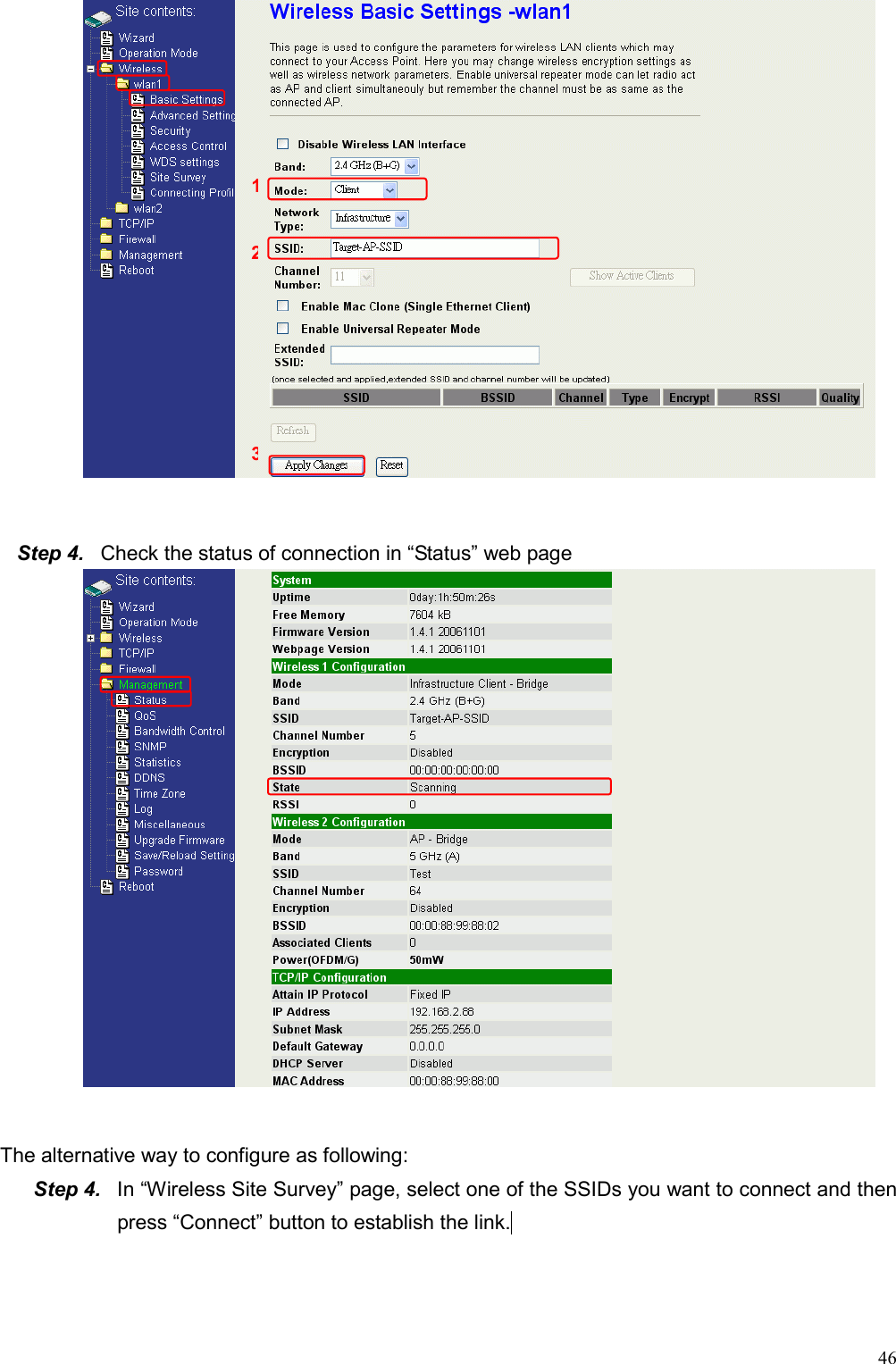
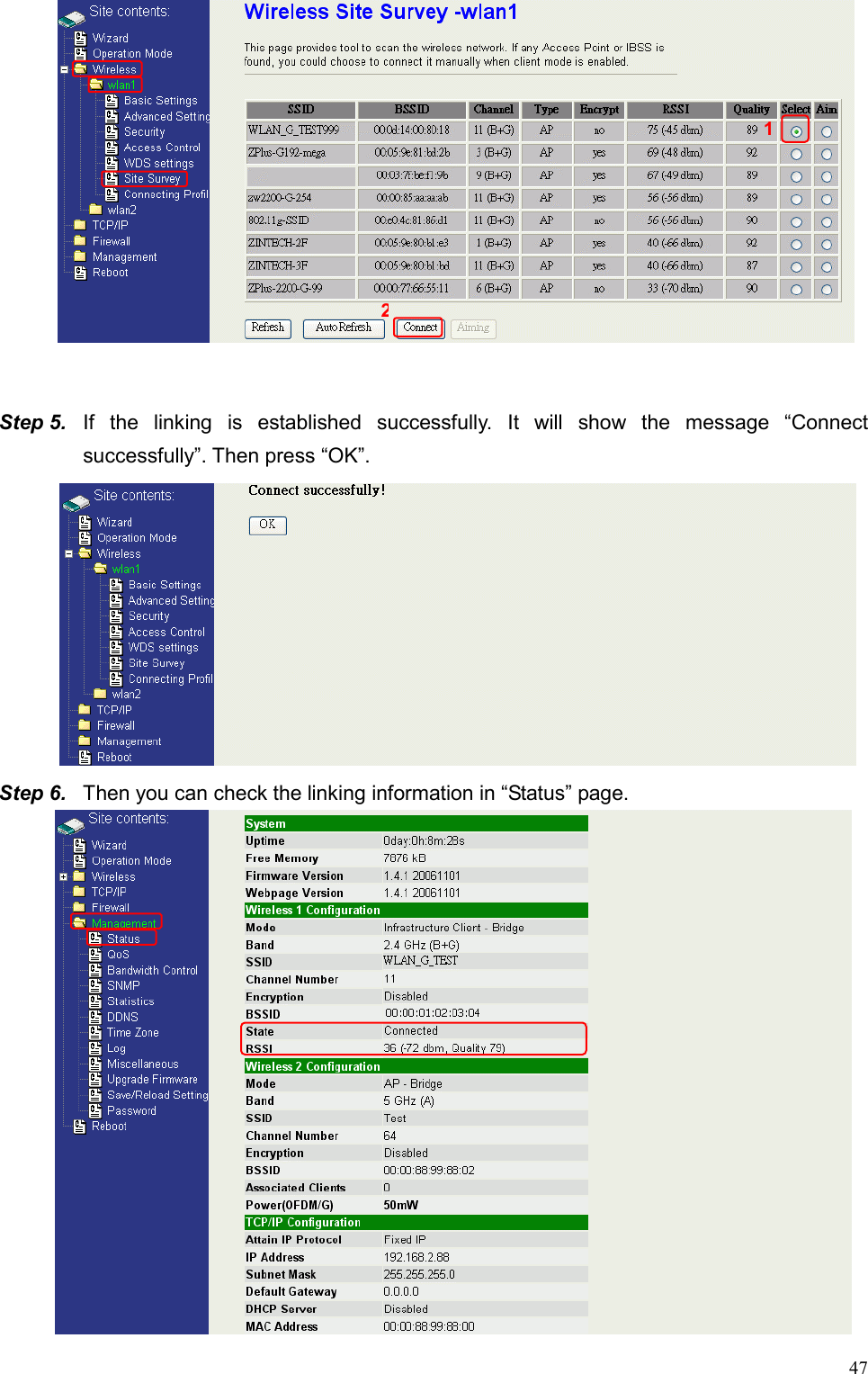
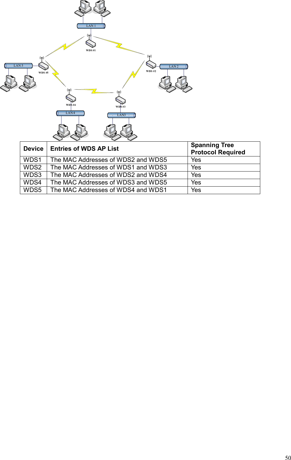
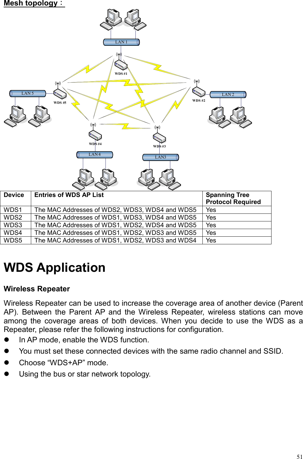
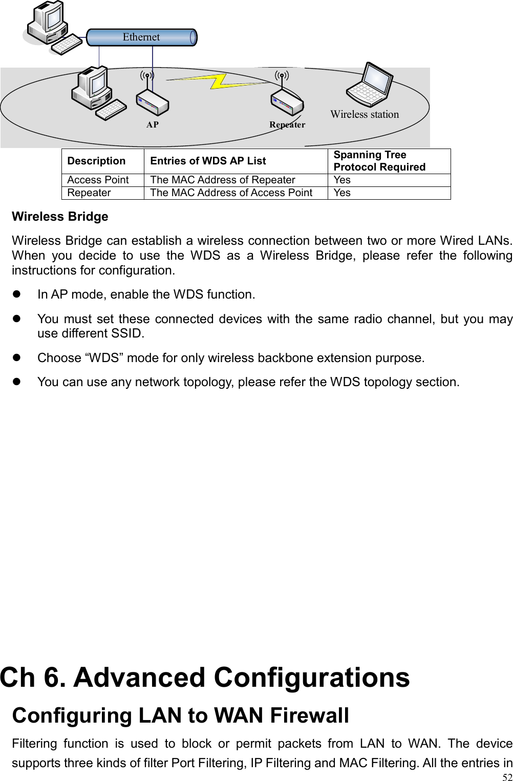
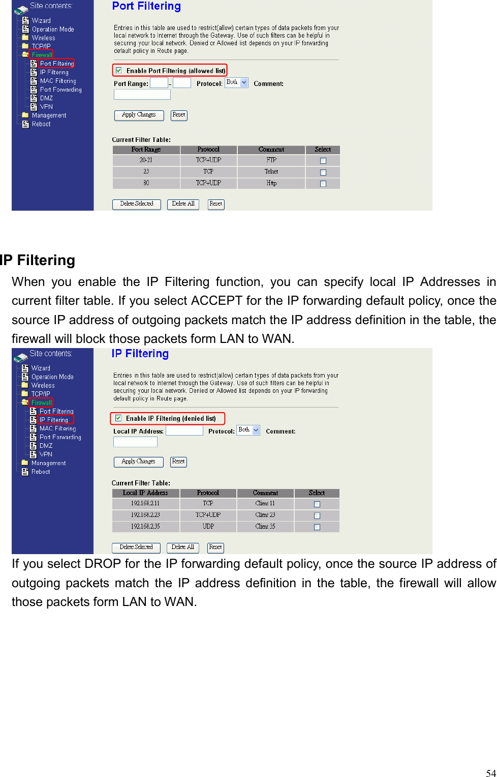
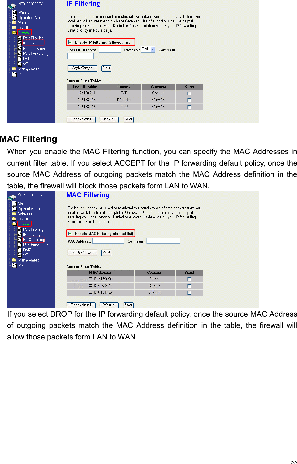
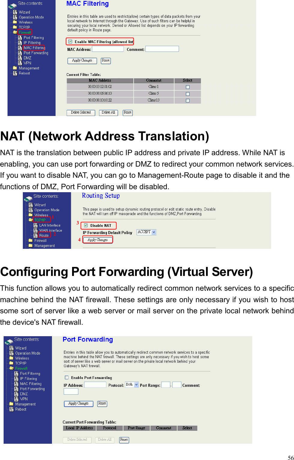
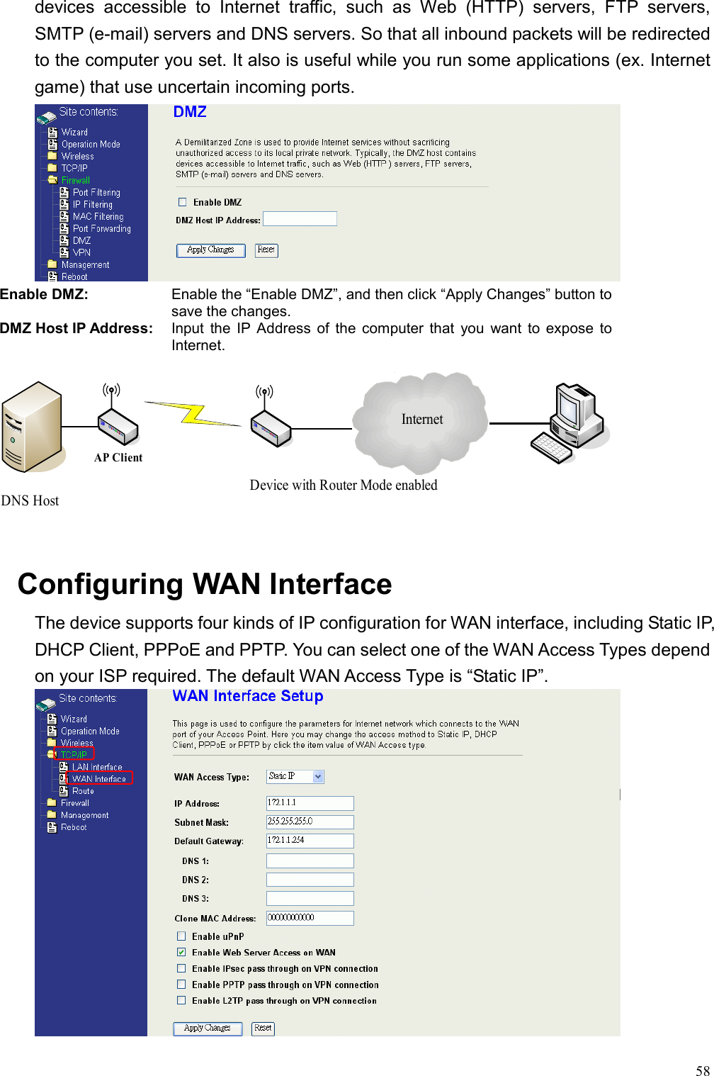
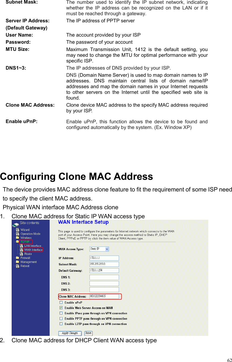


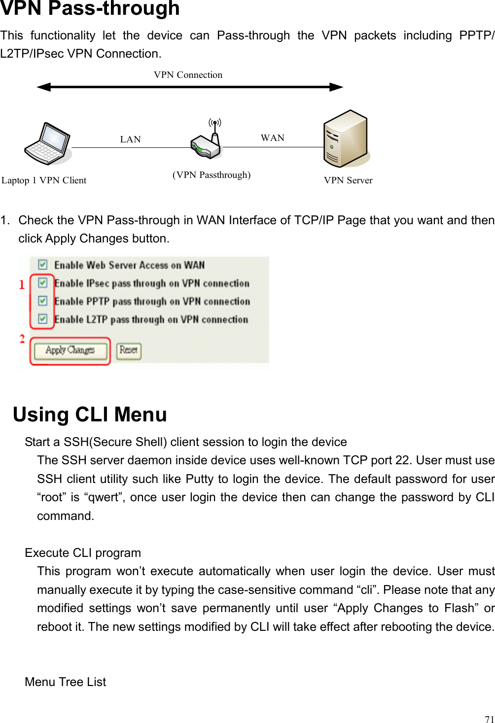
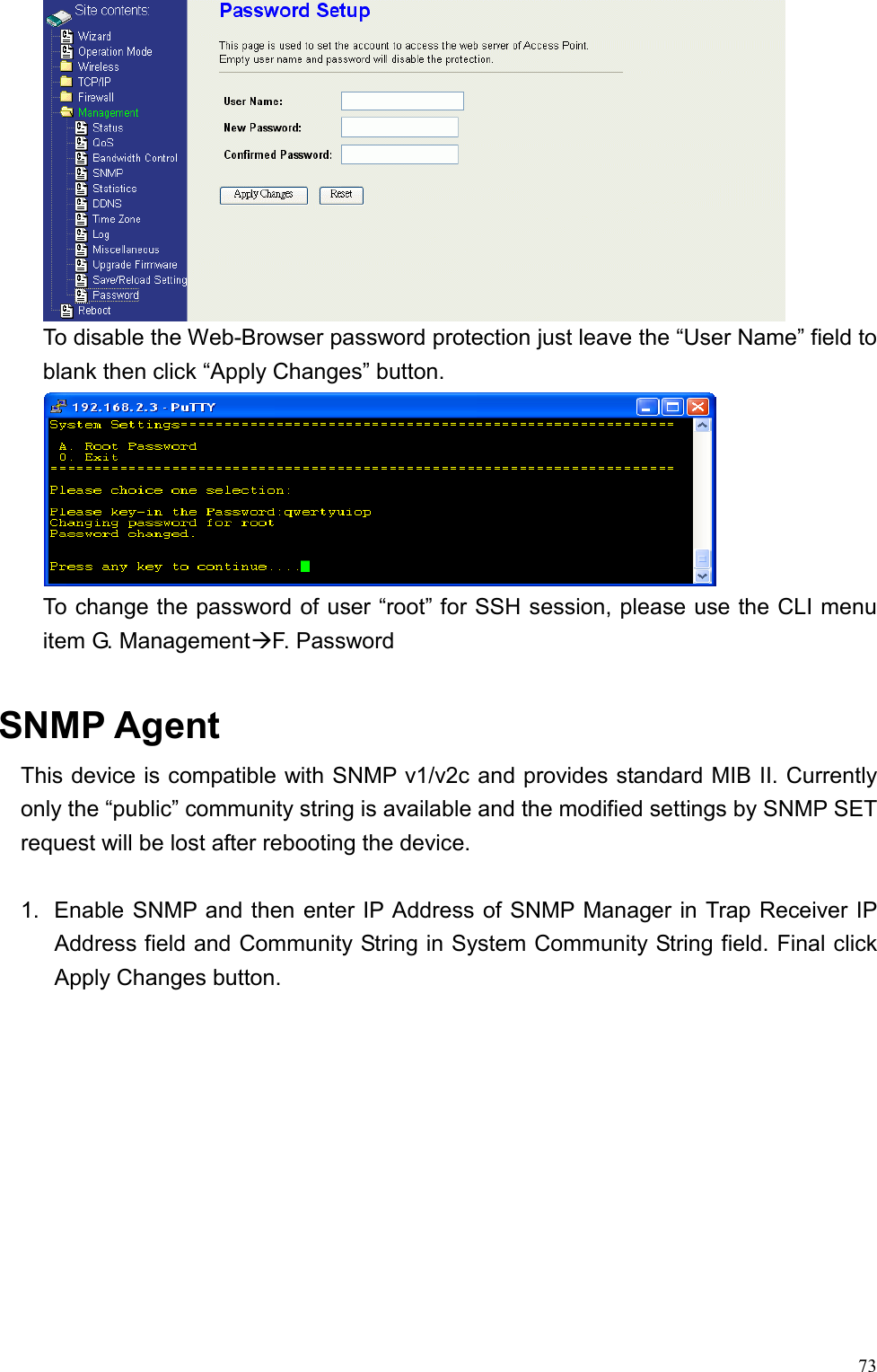
![72A. Operation Mode B. Wireless Setting C. TCP/IP-LAN Setting D. TCP/IP-WAN Setting E. Route Setting F. Firewall Setting G. Management H. Apply Changes to Flash I. Reboot to take effect 0. Exit Wireless SettingA. Basic Settings B. A dv a nced Setti ngs C. Security Settings D. Access Control Settings E. WDS Settings 0. Ex it TCP/IP WAN Settings A. WAN Type B. IP Address C. Subnet Mask D. Default Gateway E. DNS1 F. DNS2 G. DNS3 U. Clone MAC AddressV. uPNP W. Web Server Access on WAN X. IPSec passthrough on VPN connection Y. PPTP passthrough on VPN connection Z. L2TP passthrough on VPN connection 0. Exit Route Settings-[NAT]------------------------------- A. NAT B. IP Forwarding Default Policy-[Dynamic Route]------------------C. Dynamic Route D. RIP transmit to WAN E. RIP receive from WAN F. RIP transmit to LAN G. RIP receive from LAN -[Static Route ]---------------------- -H. Static Route I. Add Static Route SettingJ. Delete Static Route SettingK. Delete all Static Route SettingL. Current Static Route Setting List-[Route Table]------------------------M. Show Route Table List 0. Exit Wireless Basic Settings A. Access Point Status B. QoS Settings C. Bandwidth Control D. SNMP Settings E. Miscellaneous SettingsF. Password 0. Exit Firewall Settings A. Port Filtering B. IP Filtering C. MAC Filtering D. Port Forwarding E. DMZ F. VPN 0. Exit Operation Mode 1: Router 2: Bridge 0: CancelTCP/IP-LAN SettingA. IP Address B. Subnet Mask C. D efault Gateway D. D HCP E. DHCP Client Range F. 802.1d Spanning Tree G. Clone MAC Address H. MTU Size I. DHCP Client Table 0. Exit The System Management Password Protection Both Web-Browser and SSH configuration interfaces have password protection.](https://usermanual.wiki/Zinwell/ZW-2200.User-Manual-2-of-2/User-Guide-741284-Page-29.png)