ZyXEL Communications AMG1312T10B Wireless N ADSL2+ 4-port Gateway with USB User Manual AMG1312 T10B UG part2 REV1
ZyXEL Communications Corporation Wireless N ADSL2+ 4-port Gateway with USB AMG1312 T10B UG part2 REV1
Contents
- 1. AMG1312-T10B UG part1_REV1
- 2. AMG1312-T10B UG part2_REV1
AMG1312-T10B UG part2_REV1

AMG1312-T Series User’s Guide 161
CHAPTER 13
Dynamic DNS Setup
13.1 Overview
Dynamic DNS allows you to update your current dynamic IP address with one or many dynamic
DNS services so that anyone can contact you (in NetMeeting, CU-SeeMe, etc.). You can also access
your FTP server or Web site on your own computer using a domain name (for instance
myhost.dhs.org, where myhost is a name of your choice) that will never change instead of using an
IP address that changes each time you reconnect. Your friends or relatives will always be able to
call you even if they don't know your IP address.
First of all, you need to have registered a dynamic DNS account with www.dyndns.org. This is for
people with a dynamic IP from their ISP or DHCP server that would still like to have a domain name.
The Dynamic DNS service provider will give you a password or key.
13.1.1 What You Can Do in the DDNS Screen
Use the Dynamic DNS screen (Section 13.2 on page 161) to enable DDNS and configure the DDNS
settings on the AMG1312-T Series.
13.1.2 What You Need To Know About DDNS
DYNDNS Wildcard
Enabling the wildcard feature for your host causes *.yourhost.dyndns.org to be aliased to the same
IP address as yourhost.dyndns.org. This feature is useful if you want to be able to use, for example,
www.yourhost.dyndns.org and still reach your hostname.
If you have a private WAN IP address, then you cannot use Dynamic DNS.
13.2 The Dynamic DNS Screen
Use this screen to change your AMG1312-T Series’s DDNS. Click Network Setting > Dynamic
DNS. The screen appears as shown.
Chapter 13 Dynamic DNS Setup
AMG1312-T Series User’s Guide
162
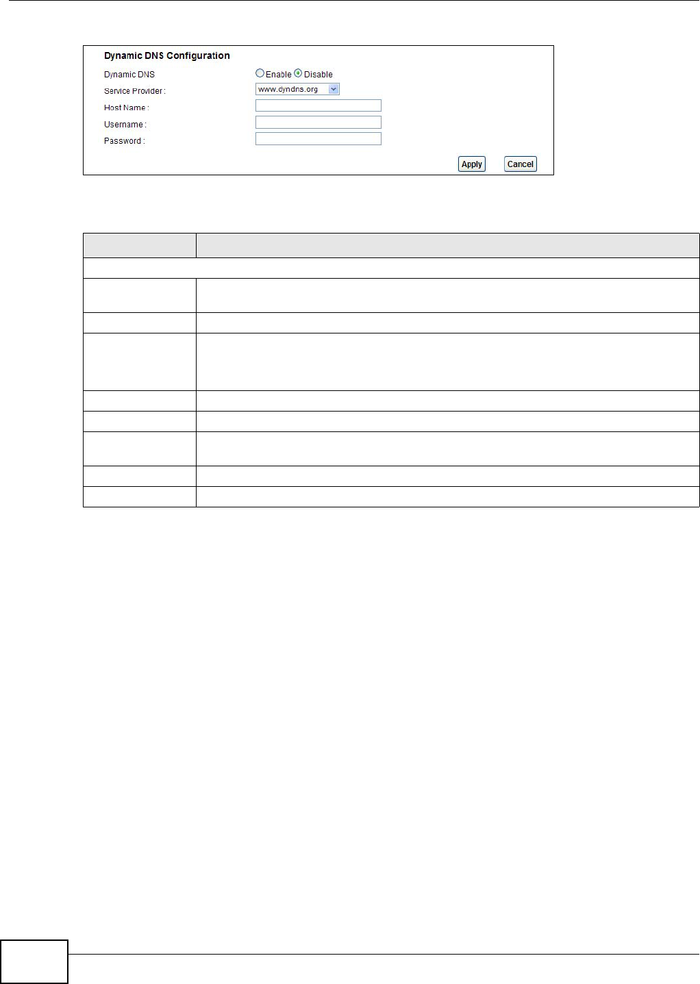
Figure 81 Network Setting > Dynamic DNS
The following table describes the fields in this screen.
Table 61 Network Setting > Dynamic DNS
LABEL DESCRIPTION
Dynamic DNS Setup
Active Dynamic
DNS
Select this check box to use dynamic DNS.
Service Provider This is the website of your Dynamic DNS service provider.
Host Name Type the domain name assigned to your AMG1312-T Series by your Dynamic DNS
provider.
You can specify up to two host names in the field separated by a comma (",").
Username Type your user name.
Password Type the password assigned to you.
Enable Wildcard
Option
Select the check box to enable DynDNS Wildcard.
Apply Click this to save your changes.
Cancel Click this to restore your previously saved settings.

AMG1312-T Series User’s Guide 163
CHAPTER 14
Filters
14.1 Overview
This chapter introduces three types of filters supported by the AMG1312-T Series. You can configure
rules to restrict traffic by IP addresses, MAC addresses, IPv6 addresses and/or URLs.
14.1.1 What You Can Do in the Filter Screens
•Use the IP/MAC Filter screen (Section 14.2 on page 163) to create IP and MAC filter rules.
•Use the IPv6/MAC Filter screen (Section 14.3 on page 166) to create IPv6 and MAC filter rules.
14.1.2 What You Need to Know About Filtering
URL
The URL (Uniform Resource Locator) identifies and helps locates resources on a network. On the
Internet the URL is the web address that you type in the address bar of your Internet browser, for
example “http://www.zyxel.com”.
URL and IP Filter Structure
The URL, IP and IPv6 filters have individual rule indexes. The AMG1312-T Series allows you to
configure each type of filter with its own respective set of rules.
14.2 The IP/MAC Filter Screen
Use this screen to create and apply IP and MAC filters. Click Security > Filter > IP/MAC Filter.
The screen appears as shown.
Chapter 14 Filters
AMG1312-T Series User’s Guide
164
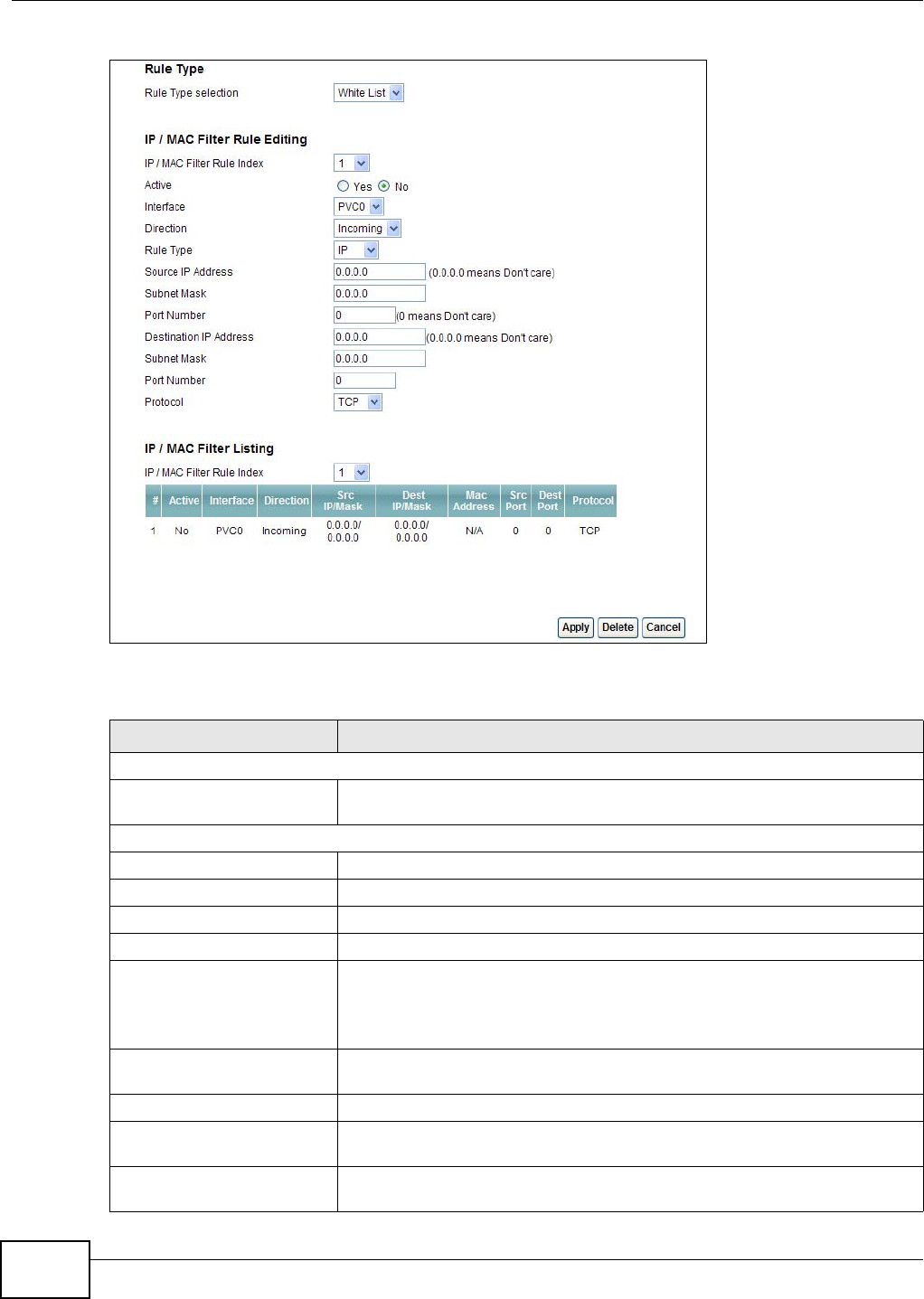
Figure 82 Security > Filter > IP/MAC Filter
The following table describes the labels in this screen.
Table 62 Security > Filter > IP/MAC Filter
LABEL DESCRIPTION
Rule Type
Rule Type selection Select White List to specify traffic to allow and Black List to specify traffic to
disallow.
IP / MAC Filter Rule Editing
IP / MAC Filter Rule Index Select the index number of the filter rule.
Active Use this field to enable or disable the filter rule.
Interface Select the PVC to which to apply the filter.
Direction Apply the filter to Incoming or Outgoing traffic direction.
Rule Type Select IP or MAC type to configure the rule.
Use the IP Filter to block or allow traffic by IP addresses.
Use the MAC Filter to block or allow traffic by MAC address.
Source IP Address Enter the source IP address of the packets you wish to filter. This field is
ignored if it is 0.0.0.0.
Subnet Mask Enter the IP subnet mask for the source IP address
Port Number Enter the source port of the packets that you wish to filter. The range of this
field is 0 to 65535. This field is ignored if it is 0.
Destination IP Address Enter the destination IP address of the packets you wish to filter. This field is
ignored if it is 0.0.0.0.
Chapter 14 Filters
AMG1312-T Series User’s Guide 165
Subnet Mask Enter the IP subnet mask for the destination IP address.
Port Number Enter the destination port of the packets that you wish to filter. The range of
this field is 0 to 65535. This field is ignored if it is 0.
Protocol Select ICMP, TCP or UDP for the upper layer protocol.
IP / MAC Filter Listing
IP / MAC Filter Rule Index Select the index number of the filter set from the drop-down list box.
#This is the index number of the rule in a filter set.
Active This field shows whether the rule is activated.
Interface This is the interface that the filter set applies to.
Direction The filter set applies to this traffic direction.
Src IP/Mask This is the source IP address and subnet mask when you select IP as the rule
type.
Dest IP/Mask This is the destination IP address and subnet mask.
Mac Address This is the MAC address of the packets being filtered.
Src Port This is the source port number.
Dest Port This is the destination port number.
Protocol This is the upper layer protocol.
Apply Click this to apply your changes.
Delete Click this to remove the filter rule.
Cancel Click this to restore your previously saved settings.
Table 62 Security > Filter > IP/MAC Filter (continued)
LABEL DESCRIPTION
Chapter 14 Filters
AMG1312-T Series User’s Guide
166
14.3 IPv6/MAC Filter
Use this screen to create and apply IPv6 filters. Click Security > Filter > IPv6/MAC Filter. The
screen appears as shown.
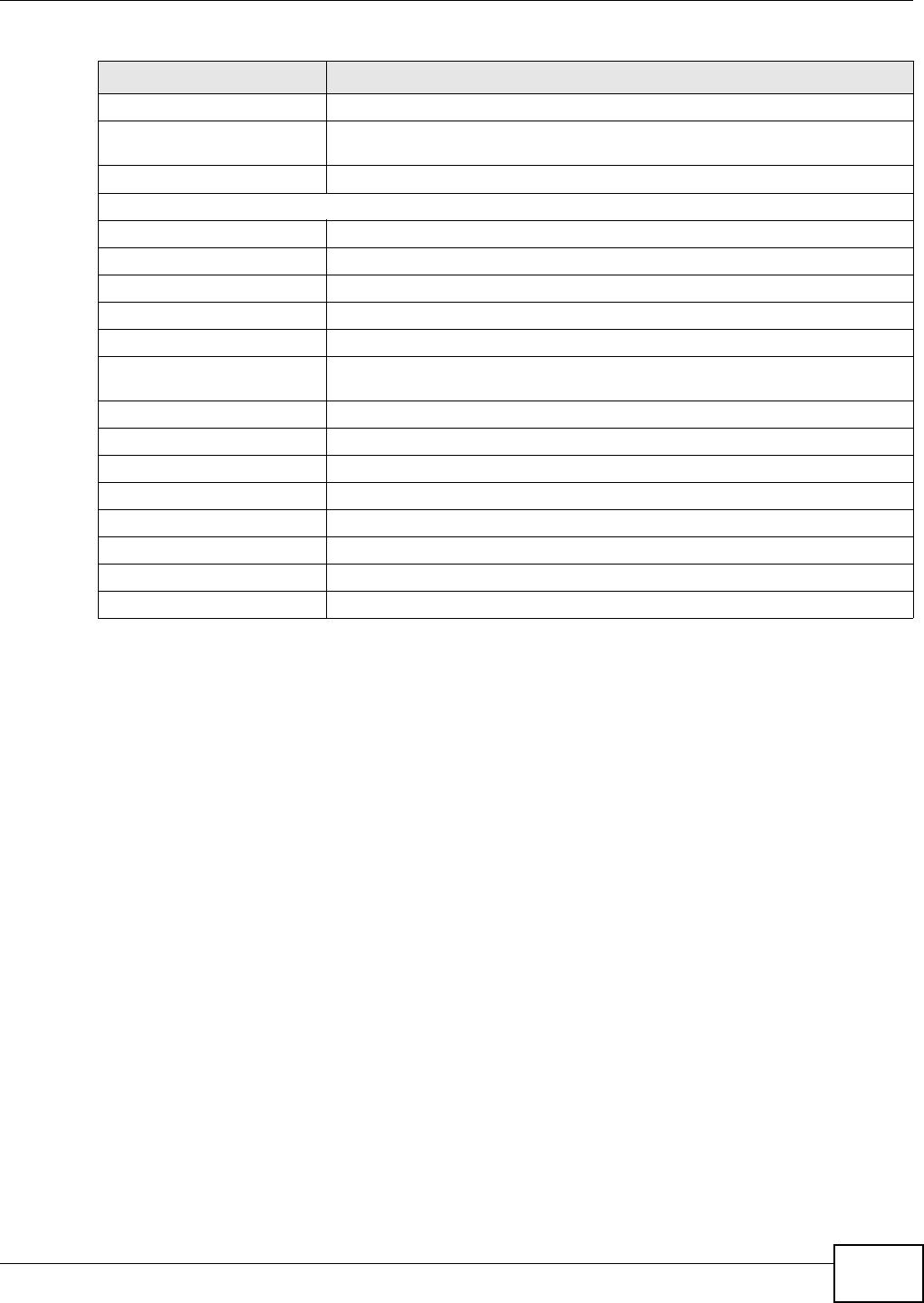
Figure 83 Security > Filter > IPv6/MAC Filter
The following table describes the labels in this screen.
Table 63 Security > Filter > IPv6/MAC Filter
LABEL DESCRIPTION
Rule Type
Rule Type selection Select White List to specify traffic to allow and Black List to specify traffic to
block.
IPv6 / MAC Filter Rule Editing
IPv6 / MAC Filter Rule Index Select the index number of the filter rule.
Active Use this field to enable or disable the filter rule.
Interface Select the PVC to which to apply the filter.
Direction Apply the filter to Incoming or Outgoing traffic direction.
Rule Type Select IP or MAC type to configure the rule.
Use the IP Filter to block or allow traffic by IPv6 addresses.
Use the MAC Filter to block or allow traffic by MAC address.
Source IP Address Enter the source IPv6 address of the packets you wish to filter. This field is
ignored if it is ::.
Source Prefix Length Enter the prefix length for the source IPv6 address
Destination IPv6 Address Enter the destination IPv6 address of the packets you wish to filter. This field is
ignored if it is ::.
Chapter 14 Filters
AMG1312-T Series User’s Guide 167
Destination Prefix Length Enter the prefix length for the destination IPv6 address.
ICMPv6 Type Select the ICMPv6 message type to filter. The following message types can be
selected:
1 / Destination Unreachable: 0 - no route to destination; 1 -
communication with destination administratively prohibited; 3 - address
unreachable; 4 - port unreachable
2 / Packet Too Big
3 / Time Exceeded: 0 - hop limit exceeded in transit; 1 - fragment
reassembly time exceeded
4 / Parameter Problem: 0 - erroneous header field encountered; 1 -
unrecognized Next Header type encountered; 2 - unrecognized IPv6 option
encountered
128 / Echo Request
129 / Echo Response
130 / Listener Query - Multicast listener query
131 / Listener Report - Multicast listener report
132 / Listener Done - Multicast listener done
143 / Listener Report v2 - Multicast listener report v2
133 / Router Solicitation
134 / Router Advertisement
135 / Neighbor Solicitation
136 / Neighbor Advertisement
137 / Redirect - Redirect message
Protocol This is the (upper layer) protocol that defines the service to which this rule
applies. By default it is ICMPv6.
IPv6 / MAC Filter Listing
IPv6 / MAC Filter Rule Index Select the index number of the filter set from the drop-down list box.
#This is the index number of the rule in a filter set.
Active This field shows whether the rule is activated.
Interface This is the interface that the rule applies to.
Direction The filter set applies to this traffic direction.
ICMPv6 Type The ICMPv6 message type to filter.
Src IP/PrefixLength This displays the source IPv6 address and prefix length.
Dest IP/PrefixLength This displays the destination IPv6 address and prefix length.
Mac Address This is the MAC address of the packets being filtered.
Protocol This is the (upper layer) protocol that defines the service to which this rule
applies. By default it is ICMPv6.
Apply Click this to apply your changes.
Delete Click this to remove the filter rule.
Cancel Click this to restore your previously saved settings.
Table 63 Security > Filter > IPv6/MAC Filter (continued)
LABEL DESCRIPTION
AMG1312-T Series User’s Guide 168
CHAPTER 15
Firewall
15.1 Overview
This chapter shows you how to enable the AMG1312-T Series firewall. Use the firewall to protect
your AMG1312-T Series and network from attacks by hackers on the Internet and control access to
it. The firewall:
• allows traffic that originates from your LAN computers to go to all other networks.
• blocks traffic that originates on other networks from going to the LAN.
• blocks SYN and port scanner attacks.
By default, the AMG1312-T Series blocks DDOS, LAND and Ping of Death attacks whether the
firewall is enabled or disabled.
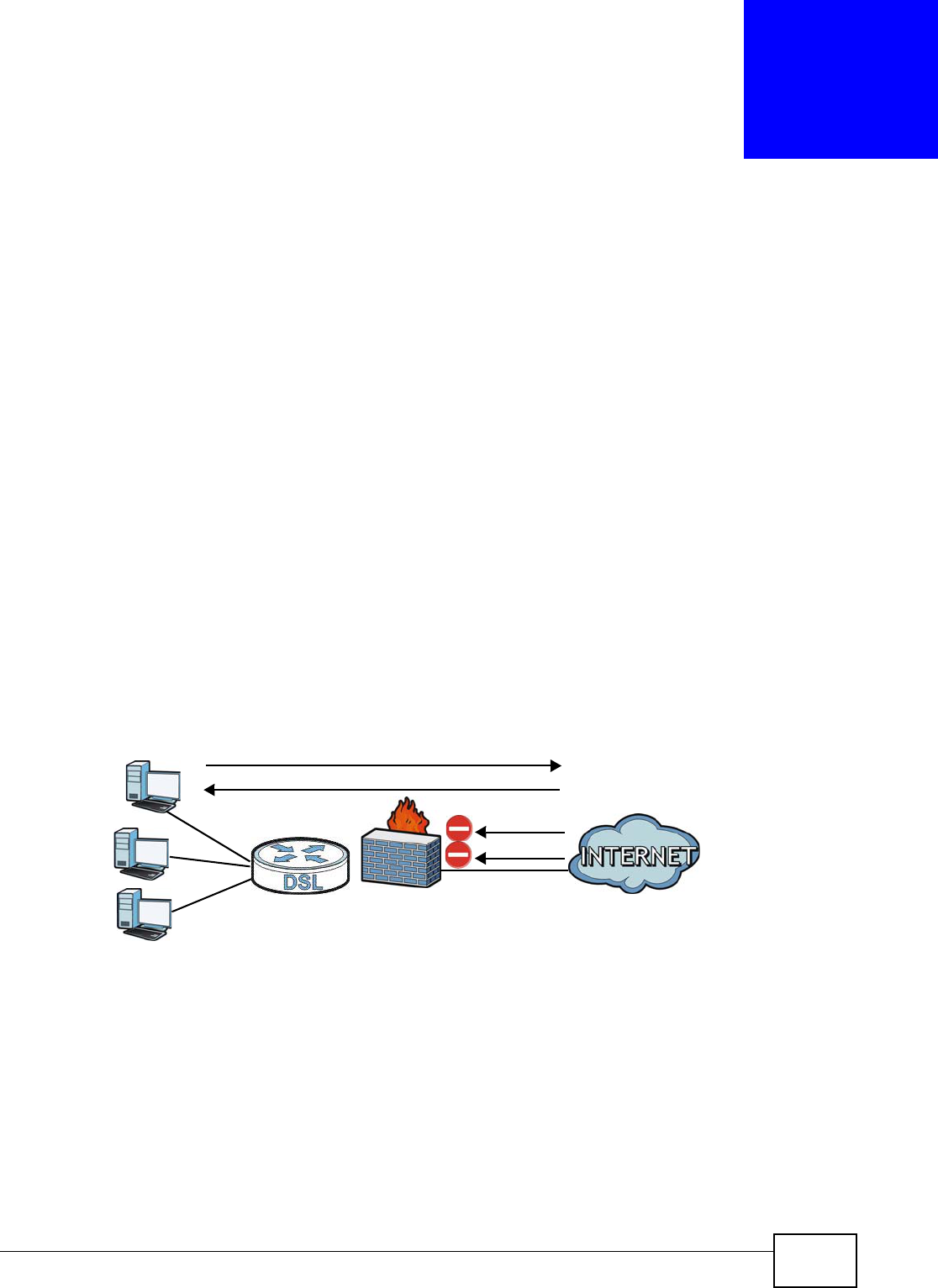
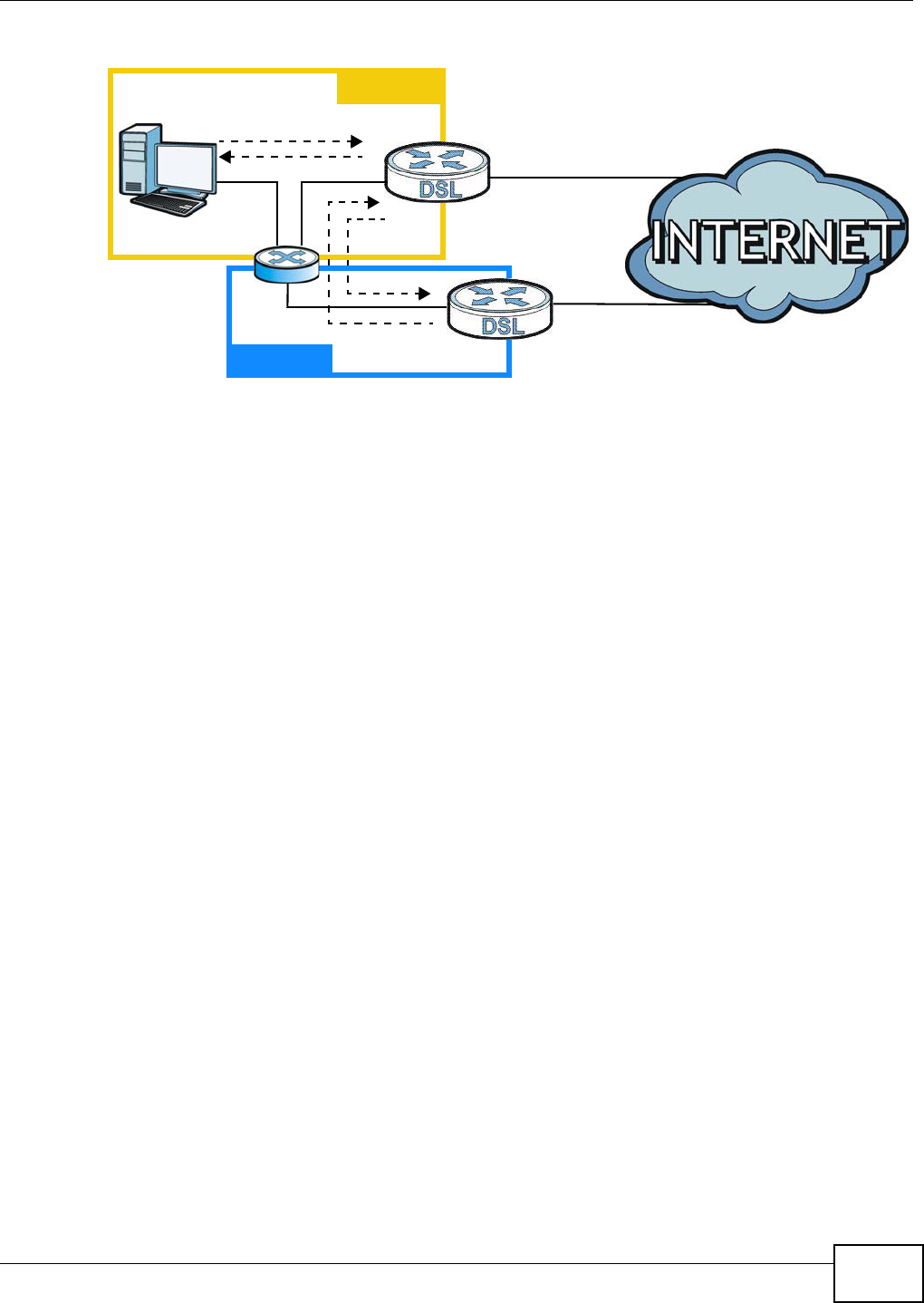
The following figure illustrates the firewall action. User A can initiate an IM (Instant Messaging)
session from the LAN to the WAN (1). Return traffic for this session is also allowed (2). However
other traffic initiated from the WAN is blocked (3 and 4).
Figure 84 Default Firewall Action
15.1.1 What You Can Do in the Firewall Screens
•Use the General screen (Section 15.2 on page 170) to select the firewall protection level on the
AMG1312-T Series.
•Use the Default Action screen (Section 15.3 on page 171) to set the default action that the
firewall takes on packets that do not match any of the firewall rules.
•Use the Rules screen (Section 15.4 on page 173) to view the configured firewall rules and add,
edit or remove a firewall rule.
•Use the Dos screen (Section 15.5 on page 179) to set the thresholds that the AMG1312-T Series
uses to determine when to start dropping sessions that do not become fully established (half-
open sessions).
WAN
LAN
3
4
1
2
A

Chapter 15 Firewall
AMG1312-T Series User’s Guide 169
15.1.2 What You Need to Know About Firewall
SYN Attack
A SYN attack floods a targeted system with a series of SYN packets. Each packet causes the
targeted system to issue a SYN-ACK response. While the targeted system waits for the ACK that
follows the SYN-ACK, it queues up all outstanding SYN-ACK responses on a backlog queue. SYN-
ACKs are moved off the queue only when an ACK comes back or when an internal timer terminates
the three-way handshake. Once the queue is full, the system will ignore all incoming SYN requests,
making the system unavailable for legitimate users.
DoS
Denials of Service (DoS) attacks are aimed at devices and networks with a connection to the
Internet. Their goal is not to steal information, but to disable a device or network so users no longer
have access to network resources. The AMG1312-T Series is pre-configured to automatically detect
and thwart all known DoS attacks.
DDoS
A Distributed DoS (DDoS) attack is one in which multiple compromised systems attack a single
target, thereby causing denial of service for users of the targeted system.
LAND Attack
In a Local Area Network Denial (LAND) attack, hackers flood SYN packets into the network with a
spoofed source IP address of the target system. This makes it appear as if the host computer sent
the packets to itself, making the system unavailable while the target system tries to respond to
itself.
Ping of Death
Ping of Death uses a "ping" utility to create and send an IP packet that exceeds the maximum
65,536 bytes of data allowed by the IP specification. This may cause systems to crash, hang or
reboot.
SPI
Stateful Packet Inspection (SPI) tracks each connection crossing the firewall and makes sure it is
valid. Filtering decisions are based not only on rules but also context. For example, traffic from the
WAN may only be allowed to cross the firewall in response to a request from the LAN.
RFC 4890 SPEC Traffic
RFC 4890 specifies the filtering policies for ICMPv6 messages. This is important for protecting
against security threats including DoS, probing, redirection attacks and renumbering attacks that
can be carried out through ICMPv6. Since ICMPv6 error messages are critical for establishing and
maintaining communications, filtering policy focuses on ICMPv6 informational messages.
Chapter 15 Firewall
AMG1312-T Series User’s Guide
170
Anti-Probing
If an outside user attempts to probe an unsupported port on your AMG1312-T Series, an ICMP
response packet is automatically returned. This allows the outside user to know the AMG1312-T
Series exists. The AMG1312-T Series supports anti-probing, which prevents the ICMP response
packet from being sent. This keeps outsiders from discovering your AMG1312-T Series when
unsupported ports are probed.
ICMP
Internet Control Message Protocol (ICMP) is a message control and error-reporting protocol
between a host server and a gateway to the Internet. ICMP uses Internet Protocol (IP) datagrams,
but the messages are processed by the TCP/IP software and directly apparent to the application
user.
DoS Thresholds
For DoS attacks, the AMG1312-T Series uses thresholds to determine when to drop sessions that do
not become fully established. These thresholds apply globally to all sessions. You can use the
default threshold values, or you can change them to values more suitable to your security
requirements.
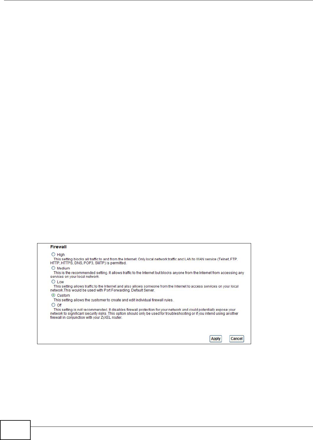
15.2 The Firewall General Screen
Use this screen to select the firewall protection level on the AMG1312-T Series. Click Security >
Firewall > General to display the following screen.
Figure 85 Security > Firewall > General
Chapter 15 Firewall
AMG1312-T Series User’s Guide 171
The following table describes the labels in this screen.
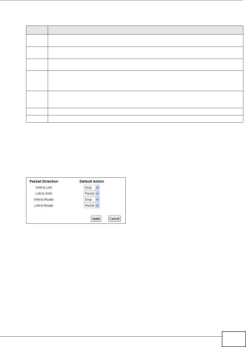
15.3 The Default Action Screen
Use this screen to set the default action that the firewall takes on packets that do not match any of
the firewall rules. Click Security > Firewall > Default Action to display the following screen.
Figure 86 Security > Firewall > Default Action
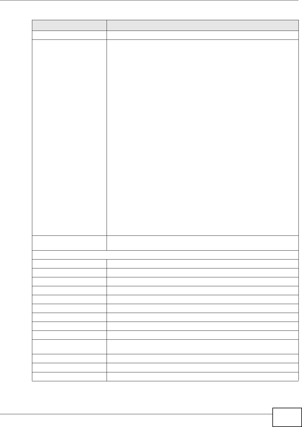
Table 64 Security > Firewall > General
LABEL DESCRIPTION
High This setting blocks all traffic to and from the Internet. Only local network traffic and LAN to WAN
service (Telnet, FTP, HTTP, HTTPS, DNS, POP3, SMTP) is permitted.
Medium This is the recommended setting. It allows traffic to the Internet but blocks anyone from the
Internet from accessing any services on your local network.
Low This setting allows traffic to the Internet and also allows someone from the Internet to access
services on your local network. This would be used with Port Forwarding, Default Server.
Custom This setting allows the customer to create and edit individual firewall rules.
Firewall rules can be created in the Default Action screen (Section 15.3 on page 171) and Rules
screen (Section 15.4 on page 173).
Off This setting is not recommended. It disables firewall protection for your network and could
potentially expose your network to significant security risks. This option should only be used for
troubleshooting or if you intend using another firewall in conjunction with your ZyXEL router.
Apply Click this to save your changes.
Cancel Click this to restore your previously saved settings.
Chapter 15 Firewall
AMG1312-T Series User’s Guide
172
The following table describes the labels in this screen.
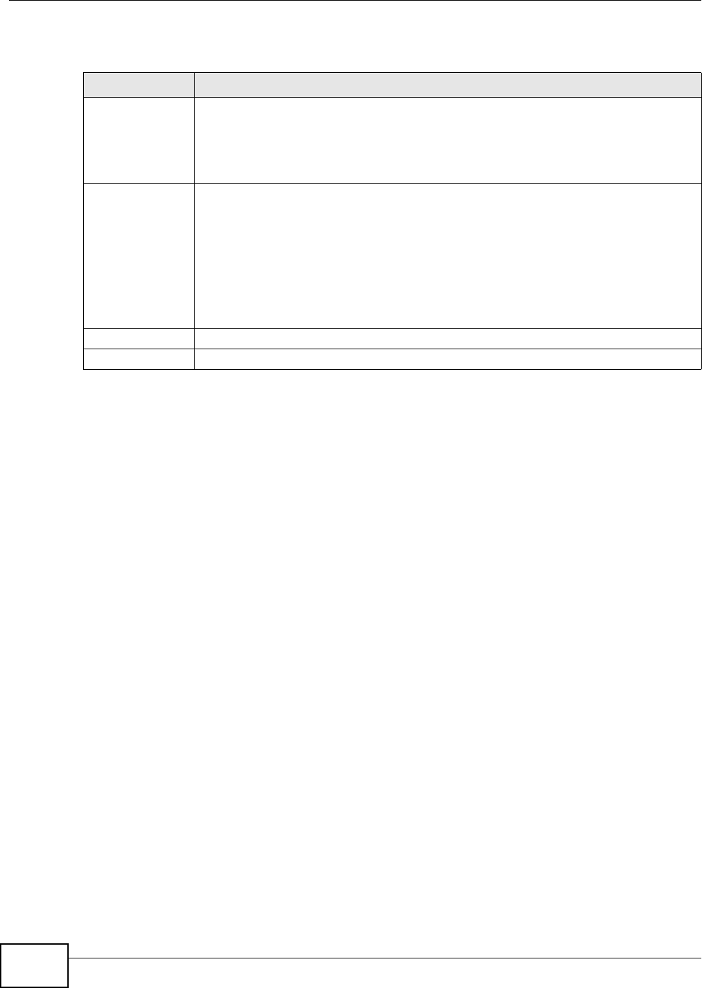
Table 65 Security > Firewall > Default Action
LABEL DESCRIPTION
Packet Direction This is the direction of travel of packets (LAN to Router, LAN to WAN, WAN to Router,
WAN to LAN).
Firewall rules are grouped based on the direction of travel of packets to which they apply.
For example, LAN to Router means packets traveling from a computer/subnet on the
LAN to the AMG1312-T Series itself.
Default Action Use the drop-down list boxes to select the default action that the firewall is to take on
packets that are traveling in the selected direction and do not match any of the firewall
rules.
Select Drop to silently discard the packets without sending a TCP reset packet or an ICMP
destination-unreachable message to the sender.
Select Reject to deny the packets and send a TCP reset packet (for a TCP packet) or an
ICMP destination-unreachable message (for a UDP packet) to the sender.
Select Permit to allow the passage of the packets.
Apply Click this to save your changes.
Cancel Click this to restore your previously saved settings.
Chapter 15 Firewall
AMG1312-T Series User’s Guide 173
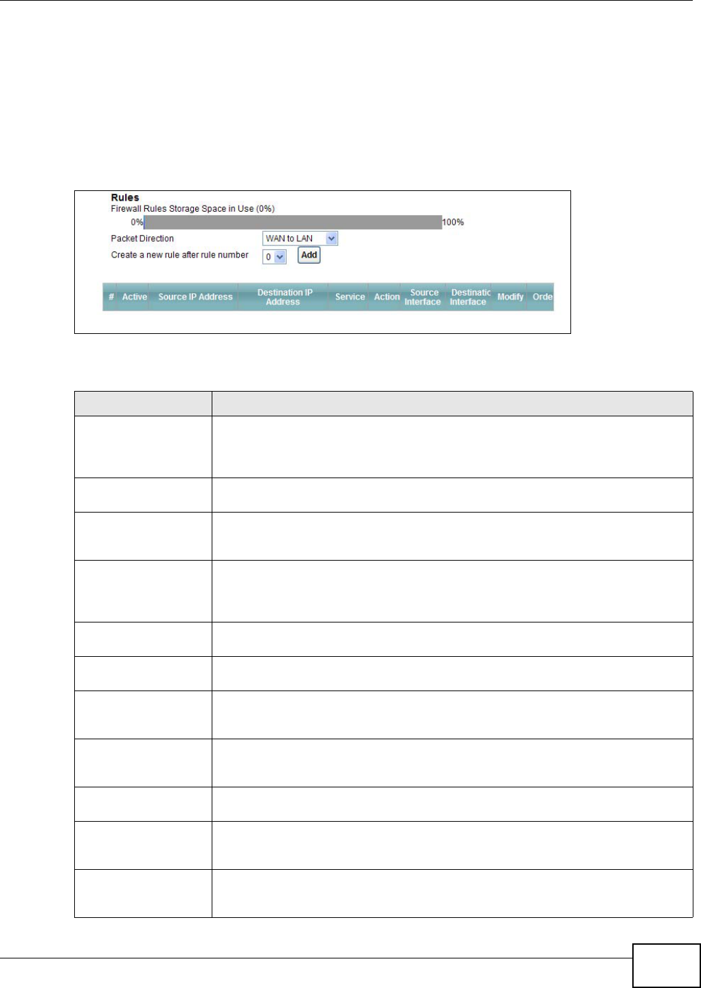
15.4 The Rules Screen
Click Security > Firewall > Rules to display the following screen. This screen displays a list of the
configured firewall rules. Note the order in which the rules are listed.
Note: The firewall configuration screen shown in this section is specific to the following
devices: P-The ordering of your rules is very important as rules are applied in turn.
Figure 87 Security > Firewall > Rules
The following table describes the labels in this screen.
Table 66 Security > Firewall > Rules
LABEL DESCRIPTION
Firewall Rules Storage
Space in Use
This read-only bar shows how much of the AMG1312-T Series's memory for
recording firewall rules it is currently using. When you are using 80% or less of the
storage space, the bar is green. When the amount of space used is over 80%, the
bar is red.
Packet Direction Use the drop-down list box to select a direction of travel of packets for which you
want to configure firewall rules.
Create a new rule
after rule number
Select an index number and click Add to add a new firewall rule after the selected
index number. For example, if you select “6”, your new rule becomes number 7 and
the previous rule 7 (if there is one) becomes rule 8.
The following read-only fields summarize the rules you have created that apply to
traffic traveling in the selected packet direction. The firewall rules that you configure
(summarized below) take priority over the general firewall action settings in the
General screen.
#This is your firewall rule number. The ordering of your rules is important as rules are
applied in turn.
Active This field displays whether a firewall is turned on or not. Select the check box to
enable the rule. Clear the check box to disable the rule.
Source IP Address This column displays the source addresses or ranges of addresses to which this
firewall rule applies. Please note that a blank source or destination address is
equivalent to Any.
Destination IP Address This column displays the destination addresses or ranges of addresses to which this
firewall rule applies. Please note that a blank source or destination address is
equivalent to Any.
Service This column displays the services to which this firewall rule applies. See Appendix F
on page 286 for more information.
Action This field displays whether the firewall silently discards packets (Drop), discards
packets and sends a TCP reset packet or an ICMP destination-unreachable message
to the sender (Reject) or allows the passage of packets (Permit).
Source Interface This column displays the source interface to which this firewall rule applies. This is
the interface through which the traffic entered the AMG1312-T Series. Please note
that a blank source interface is equivalent to Any.
Chapter 15 Firewall
AMG1312-T Series User’s Guide
174
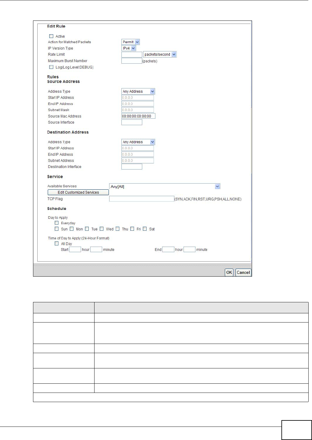
15.4.1 The Rules Add Screen
Use this screen to configure firewall rules. In the Rules screen, select an index number and click
Add or click a rule’s Edit icon to display this screen and refer to the following table for information
on the labels.
Destination Interface This column displays the destination interface to which this firewall rule applies. This
is the interface through which the traffic is destined to leave the AMG1312-T Series.
Please note that a blank source interface is equivalent to Any.
Modify Click the Edit icon to go to the screen where you can edit the rule.
Click the Remove icon to delete an existing firewall rule. A window displays asking
you to confirm that you want to delete the firewall rule. Note that subsequent firewall
rules move up by one when you take this action.
Apply Click this to save your changes.
Cancel Click this to restore your previously saved settings.
Table 66 Security > Firewall > Rules (continued)
LABEL DESCRIPTION
Chapter 15 Firewall
AMG1312-T Series User’s Guide 175
Figure 88 Security > Firewall > Rules > Add
The following table describes the labels in this screen.
Table 67 Security > Firewall > Rules > Add
LABEL DESCRIPTION
Active Select this option to enable this firewall rule.
Action for Matched
Packets
Use the drop-down list box to select whether to discard (Drop), deny and send an
ICMP destination-unreachable message to the sender of (Reject) or allow the
passage of (Permit) packets that match this rule.
IP Version Type Select the IP version, IPv4 or IPv6, to apply this firewall rule to.
Rate Limit Set a maximum number of packets per second, minute, or hour to limit the
throughput of traffic that matches this rule.
Maximum Burst
Number
Set the maximum number of packets that can be sent at the peak rate.
Log This field determines if a log for packets that match the rule is created or not.
Rules/Destination Address
Chapter 15 Firewall
AMG1312-T Series User’s Guide
176
15.4.2 Customized Services
Configure customized services and port numbers not predefined by the AMG1312-T Series. For a
comprehensive list of port numbers and services, visit the IANA (Internet Assigned Number
Authority) website. See Appendix F on page 286 for some examples. Click the Edit Customized
Services button while editing a firewall rule to configure a custom service port. This displays the
following screen.
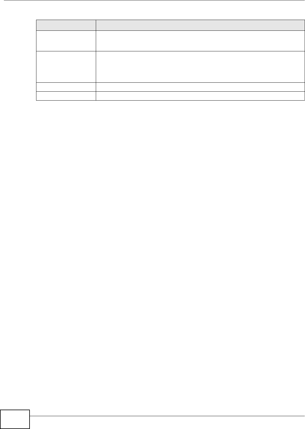
Address Type Do you want your rule to apply to packets with a particular (single) IP, a range of IP
addresses (for instance, 192.168.1.10 to 192.169.1.50), a subnet or any IP address?
Select an option from the drop-down list box that includes: Single Address, Range
Address, Subnet Address and Any Address.
Start IP Address Enter the single IP address or the starting IP address in a range here.
End IP Address Enter the ending IP address in a range here.
Subnet Mask Enter the subnet mask here, if applicable.
Source Mac Address Specify a source MAC address of traffic to which to apply this firewall rule applies.
Please note that a blank source MAC address is equivalent to any.
Source Interface Specify a source interface to which this firewall rule applies. This is the interface
through which the traffic entered the AMG1312-T Series. Please note that a blank
source interface is equivalent to any.
Destination Interface Specify a destination interface to which this firewall rule applies. This is the interface
through which the traffic is destined to leave the AMG1312-T Series. Please note that
a blank source interface is equivalent to any.
Services
Available Services Please see Appendix F on page 286 for more information on services available. Select
a service from the Available Services box.
Edit Customized
Service
Click the Edit Customized Service button to bring up the screen that you use to
configure a new custom service that is not in the predefined list of services.
TCP Flag Specify any TCP flag bits the firewall rule is to check for.
Schedule Select the days and time during which to apply the rule. Select Everyday and All
Day to always apply the rule.
Apply Click this to save your changes.
Cancel Click this to restore your previously saved settings.
Table 67 Security > Firewall > Rules > Add (continued)
LABEL DESCRIPTION
Chapter 15 Firewall
AMG1312-T Series User’s Guide 177
Figure 89 Security > Firewall > Rules: Edit: Edit Customized Services
The following table describes the labels in this screen.
15.4.3 Customized Service Add/Edit
Use this screen to add a customized rule or edit an existing rule. Click Add or the Edit icon next to
a rule number in the Firewall Customized Services screen to display the following screen.
Figure 90 Security > Firewall > Rules: Edit: Edit Customized Services: Add/Edit
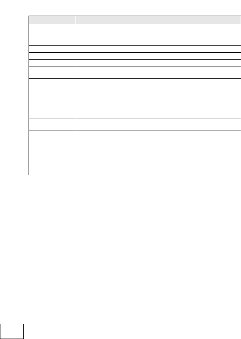
Table 68 Security > Firewall > Rules: Edit: Edit Customized Services
LABEL DESCRIPTION
#This is the number of your customized port.
Name This is the name of your customized service.
Protocol This shows the IP protocol (TCP or UDP) that defines your customized service.
Port Type This is the port number or range that defines your customized service.
Start Port This is a single port number or the starting port number of a range that defines your
customized service.
End Port This is a single port number or the ending port number of a range that defines your customized
service.
Modify Click this to edit a customized service.
Add Click this to configure a customized service.
Back Click this to return to the Firewall Edit Rule screen.
Chapter 15 Firewall
AMG1312-T Series User’s Guide
178
The following table describes the labels in this screen.
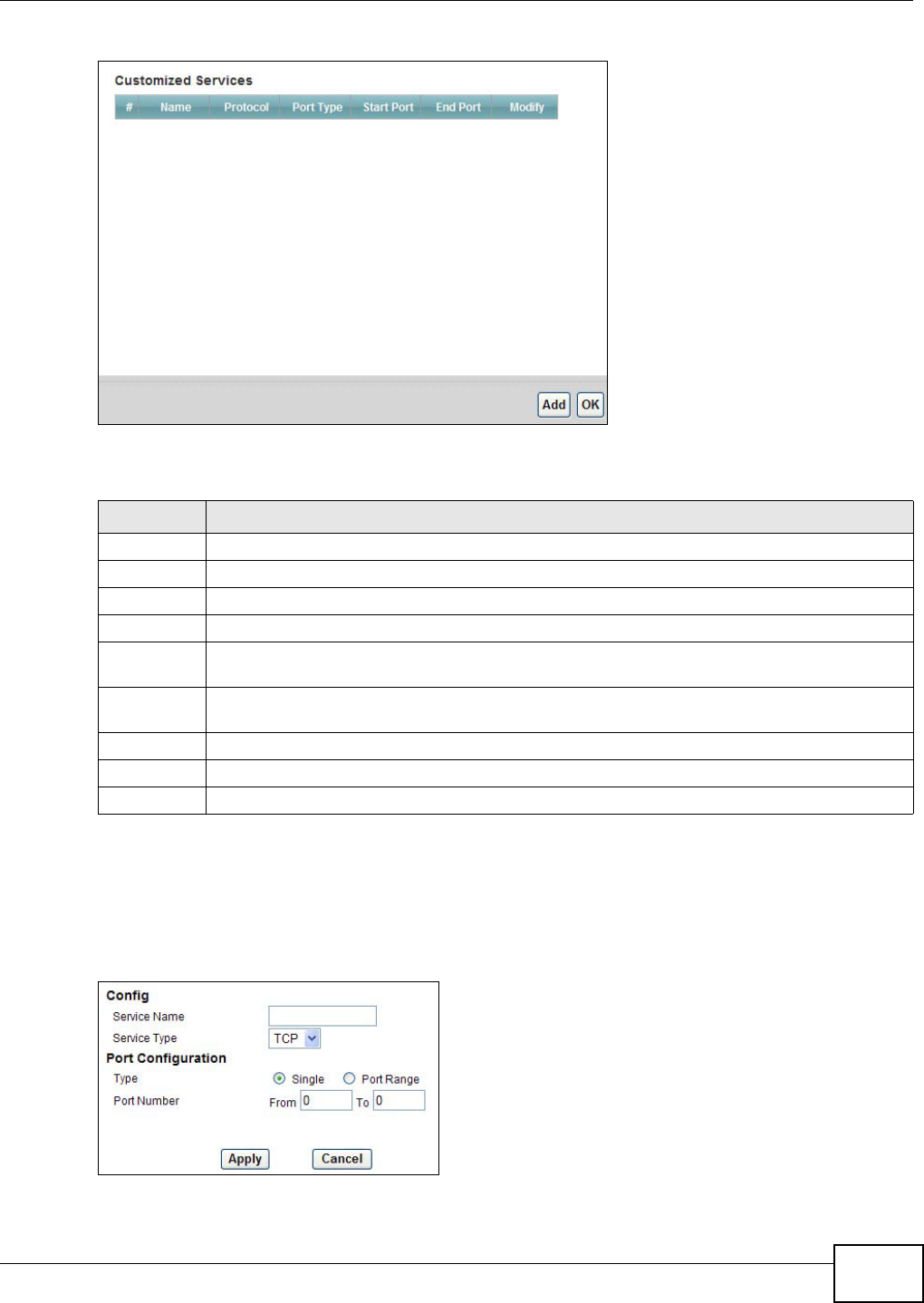
Table 69 Security > Firewall > Rules: Edit: Edit Customized Services: Add/Edit
LABEL DESCRIPTION
Config
Service Name Type a unique name for your custom port.
Service Type Choose the IP port (TCP or UDP) that defines your customized port from the drop down list
box.
Port Configuration
Type Click Single to specify one port only or Port Range to specify a span of ports that define
your customized service.
Port Number Type a single port number or the range of port numbers that define your customized
service.
Back Click this to return to the previous screen without saving.
Apply Click this to save your changes.
Cancel Click this to restore your previously saved settings.
Delete Click this to delete the current rule.
Chapter 15 Firewall
AMG1312-T Series User’s Guide 179
15.5 The DoS Screen
Use this screen to enable DoS protection. Click Security > Firewall > Dos to display the following
screen.
Figure 91 Security > Firewall > Dos
The following table describes the labels in this screen.
15.5.1 The DoS Advanced Screen
For DoS attacks, the AMG1312-T Series uses thresholds to determine when to start dropping
sessions that do not become fully established (half-open sessions). These thresholds apply globally
to all sessions.
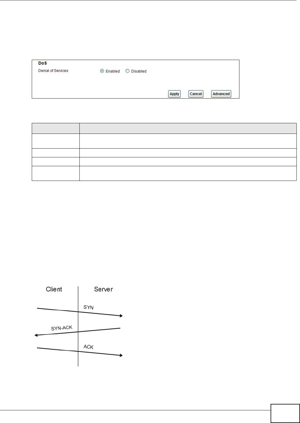
For TCP, half-open means that the session has not reached the established state-the TCP three-way
handshake has not yet been completed. Under normal circumstances, the application that initiates
a session sends a SYN (synchronize) packet to the receiving server. The receiver sends back an ACK
(acknowledgment) packet and its own SYN, and then the initiator responds with an ACK
(acknowledgment). After this handshake, a connection is established.
Figure 92 Three-Way Handshake
For UDP, half-open means that the firewall has detected no return traffic. An unusually high number
(or arrival rate) of half-open sessions could indicate a DOS attack.
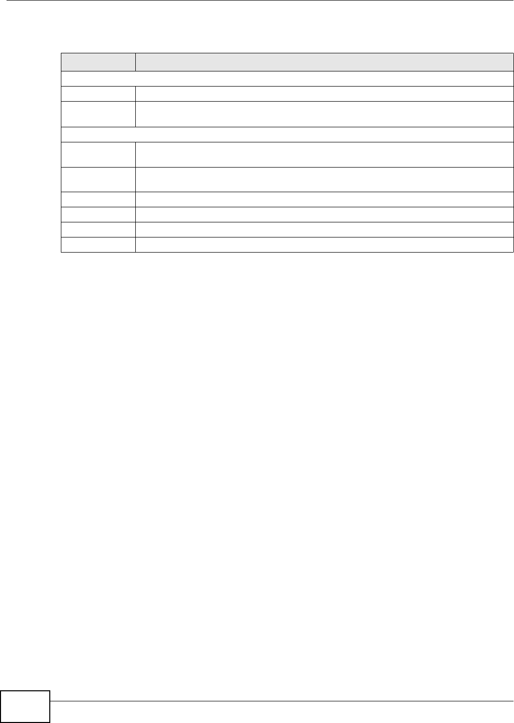
Table 70 Security > Firewall > Dos
LABEL DESCRIPTION
Denial of Services Enable this to protect against DoS attacks. The AMG1312-T Series will drop sessions that
surpass maximum thresholds.
Apply Click this to save your changes.
Cancel Click this to restore your previously saved settings.
Advanced Click this to go to a screen to specify maximum thresholds at which the AMG1312-T
Series will start dropping sessions.
Chapter 15 Firewall
AMG1312-T Series User’s Guide
180
15.5.1.1 Threshold Values
If everything is working properly, you probably do not need to change the threshold settings as the
default threshold values should work for most small offices. Tune these parameters when you
believe the AMG1312-T Series has been receiving DoS attacks that are not recorded in the logs or
the logs show that the AMG1312-T Series is classifying normal traffic as DoS attacks. Factors
influencing choices for threshold values are:
1The maximum number of opened sessions.
2The minimum capacity of server backlog in your LAN network.
3The CPU power of servers in your LAN network.
4Network bandwidth.
5Type of traffic for certain servers.
Reduce the threshold values if your network is slower than average for any of these factors
(especially if you have servers that are slow or handle many tasks and are often busy).
• If you often use P2P applications such as file sharing with eMule or eDonkey, it’s recommended
that you increase the threshold values since lots of sessions will be established during a small
period of time and the AMG1312-T Series may classify them as DoS attacks.
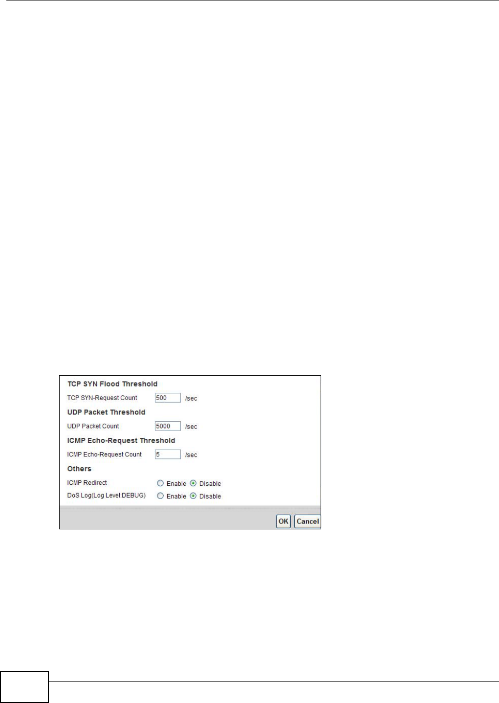
15.5.2 Configuring Firewall Thresholds
Click Security > Firewall > DoS > Advanced to display the following screen.
Figure 93 Security > Firewall > DoS > Advanced
Chapter 15 Firewall
AMG1312-T Series User’s Guide 181
The following table describes the labels in this screen.
15.6 Firewall Technical Reference
This section provides some technical background information about the topics covered in this
chapter.
15.6.1 Firewall Rules Overview
Your customized rules take precedence and override the AMG1312-T Series’s default settings. The
AMG1312-T Series checks the source IP address, destination IP address and IP protocol type of
network traffic against the firewall rules (in the order you list them). When the traffic matches a
rule, the AMG1312-T Series takes the action specified in the rule.
Firewall rules are grouped based on the direction of travel of packets to which they apply:
Note: The LAN includes both the LAN port and the WLAN.
By default, the AMG1312-T Series’s stateful packet inspection allows packets traveling in the
following directions:
•LAN to Router
These rules specify which computers on the LAN can manage the AMG1312-T Series (remote
management).
Note: You can also configure the remote management settings to allow only a specific
computer to manage the AMG1312-T Series.
Table 71 Security > Firewall > DoS > Advanced
LABEL DESCRIPTION
TCP SYN-Request
Count
This is the rate of new TCP half-open sessions per second that causes the firewall to
start deleting half-open sessions. When the rate of new connection attempts rises
above this number, the AMG1312-T Series deletes half-open sessions as required to
accommodate new connection attempts.
UDP Packet Count This is the rate of new UDP half-open sessions per second that causes the firewall to
start deleting half-open sessions. When the rate of new connection attempts rises
above this number, the AMG1312-T Series deletes half-open sessions as required to
accommodate new connection attempts.
ICMP Echo-Request
Count
This is the rate of new ICMP Echo-Request half-open sessions per second that causes
the firewall to start deleting half-open sessions. When the rate of new connection
attempts rises above this number, the AMG1312-T Series deletes half-open sessions
as required to accommodate new connection attempts.
Back Click this button to return to the previous screen.
Apply Click this to save your changes.
Cancel Click this to restore your previously saved settings.
•LAN to Router •WAN to LAN
• LAN to WAN • WAN to Router

Chapter 15 Firewall
AMG1312-T Series User’s Guide
182
•LAN to WAN
These rules specify which computers on the LAN can access which computers or services on the
WAN.
By default, the AMG1312-T Series’s stateful packet inspection drops packets traveling in the
following directions:
•WAN to LAN
These rules specify which computers on the WAN can access which computers or services on the
LAN.
Note: You also need to configure NAT port forwarding (or full featured NAT address
mapping rules) to allow computers on the WAN to access devices on the LAN.
•WAN to Router
By default the AMG1312-T Series stops computers on the WAN from managing the AMG1312-T
Series. You could configure one of these rules to allow a WAN computer to manage the
AMG1312-T Series.
Note: You also need to configure the remote management settings to allow a WAN
computer to manage the AMG1312-T Series.
You may define additional rules and sets or modify existing ones but please exercise extreme
caution in doing so.
For example, you may create rules to:
• Block certain types of traffic, such as IRC (Internet Relay Chat), from the LAN to the Internet.
• Allow certain types of traffic, such as Lotus Notes database synchronization, from specific hosts
on the Internet to specific hosts on the LAN.
• Allow everyone except your competitors to access a web server.
• Restrict use of certain protocols, such as Telnet, to authorized users on the LAN.
These custom rules work by comparing the source IP address, destination IP address and IP
protocol type of network traffic to rules set by the administrator. Your customized rules take
precedence and override the AMG1312-T Series’s default rules.
15.6.2 Guidelines For Enhancing Security With Your Firewall
6Change the default password via web configurator.
7Think about access control before you connect to the network in any way.
8Limit who can access your router.
9Don't enable any local service (such as telnet or FTP) that you don't use. Any enabled service could
present a potential security risk. A determined hacker might be able to find creative ways to misuse
the enabled services to access the firewall or the network.
10 For local services that are enabled, protect against misuse. Protect by configuring the services to
communicate only with specific peers, and protect by configuring rules to block packets for the
services at specific interfaces.
Chapter 15 Firewall
AMG1312-T Series User’s Guide 183
11 Protect against IP spoofing by making sure the firewall is active.
12 Keep the firewall in a secured (locked) room.
15.6.3 Security Considerations
Note: Incorrectly configuring the firewall may block valid access or introduce security
risks to the AMG1312-T Series and your protected network. Use caution when
creating or deleting firewall rules and test your rules after you configure them.
Consider these security ramifications before creating a rule:
1Does this rule stop LAN users from accessing critical resources on the Internet? For example, if IRC
is blocked, are there users that require this service?
2Is it possible to modify the rule to be more specific? For example, if IRC is blocked for all users, will
a rule that blocks just certain users be more effective?
3Does a rule that allows Internet users access to resources on the LAN create a security
vulnerability? For example, if FTP ports (TCP 20, 21) are allowed from the Internet to the LAN,
Internet users may be able to connect to computers with running FTP servers.
4Does this rule conflict with any existing rules?
Once these questions have been answered, adding rules is simply a matter of entering the
information into the correct fields in the web configurator screens.
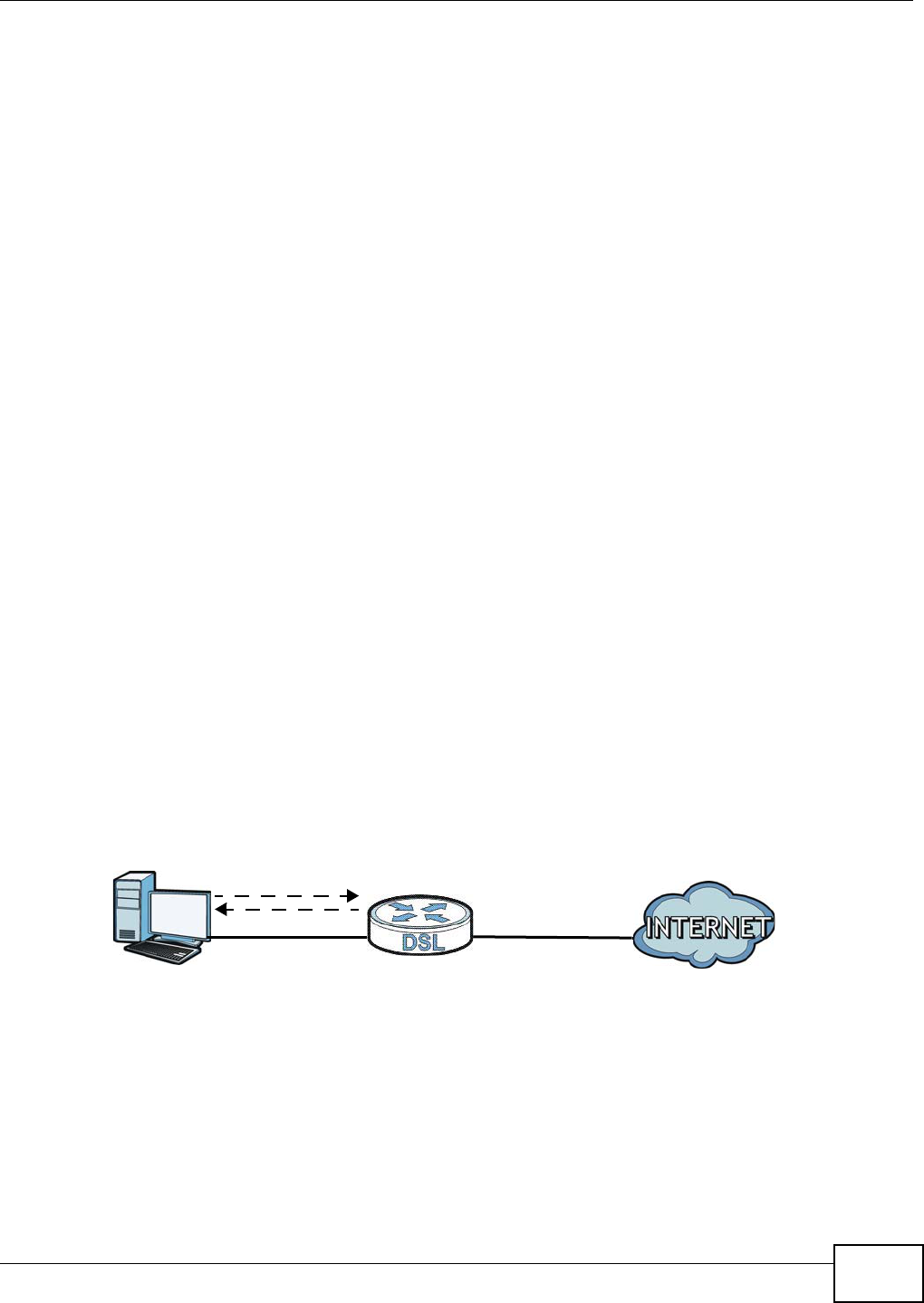
15.6.4 Triangle Route
When the firewall is on, your AMG1312-T Series acts as a secure gateway between your LAN and
the Internet. In an ideal network topology, all incoming and outgoing network traffic passes
through the AMG1312-T Series to protect your LAN against attacks.
Figure 94 Ideal Firewall Setup
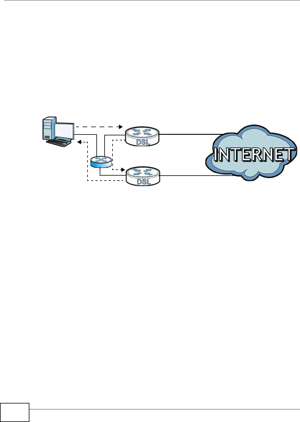
15.6.4.1 The “Triangle Route” Problem
A traffic route is a path for sending or receiving data packets between two Ethernet devices. You
may have more than one connection to the Internet (through one or more ISPs). If an alternate
gateway is on the LAN (and its IP address is in the same subnet as the AMG1312-T Series’s LAN IP
address), the “triangle route” (also called asymmetrical route) problem may occur. The steps below
describe the “triangle route” problem.
1
2
WAN
LAN
Chapter 15 Firewall
AMG1312-T Series User’s Guide
184
1A computer on the LAN initiates a connection by sending out a SYN packet to a receiving server on
the WAN.
2The AMG1312-T Series reroutes the SYN packet through Gateway A on the LAN to the WAN.
3The reply from the WAN goes directly to the computer on the LAN without going through the
AMG1312-T Series.
As a result, the AMG1312-T Series resets the connection, as the connection has not been
acknowledged.
Figure 95 “Triangle Route” Problem
15.6.4.2 Solving the “Triangle Route” Problem
If you have the AMG1312-T Series allow triangle route sessions, traffic from the WAN can go
directly to a LAN computer without passing through the AMG1312-T Series and its firewall
protection.
Another solution is to use IP alias. IP alias allows you to partition your network into logical sections
over the same Ethernet interface. Your AMG1312-T Series supports up to three logical LAN
interfaces with the AMG1312-T Series being the gateway for each logical network.
It’s like having multiple LAN networks that actually use the same physical cables and ports. By
putting your LAN and Gateway A in different subnets, all returning network traffic must pass
through the AMG1312-T Series to your LAN. The following steps describe such a scenario.
1A computer on the LAN initiates a connection by sending a SYN packet to a receiving server on the
WAN.
2The AMG1312-T Series reroutes the packet to Gateway A, which is in Subnet 2.
3The reply from the WAN goes to the AMG1312-T Series.
4The AMG1312-T Series then sends it to the computer on the LAN in Subnet 1.
1
2
3
WAN
LAN
A
ISP 1
ISP 2
Chapter 15 Firewall
AMG1312-T Series User’s Guide 185
Figure 96 IP Alias
1
2
3
LAN
A
ISP 1
ISP 2
4
WAN
Subnet 1
Subnet 2
AMG1312-T Series User’s Guide 186
CHAPTER 16
Parental Control
16.1 Overview
Parental control allows you to block web sites with the specific URL. You can also define time
periods and days during which the AMG1312-T Series performs parental control on a specific user.
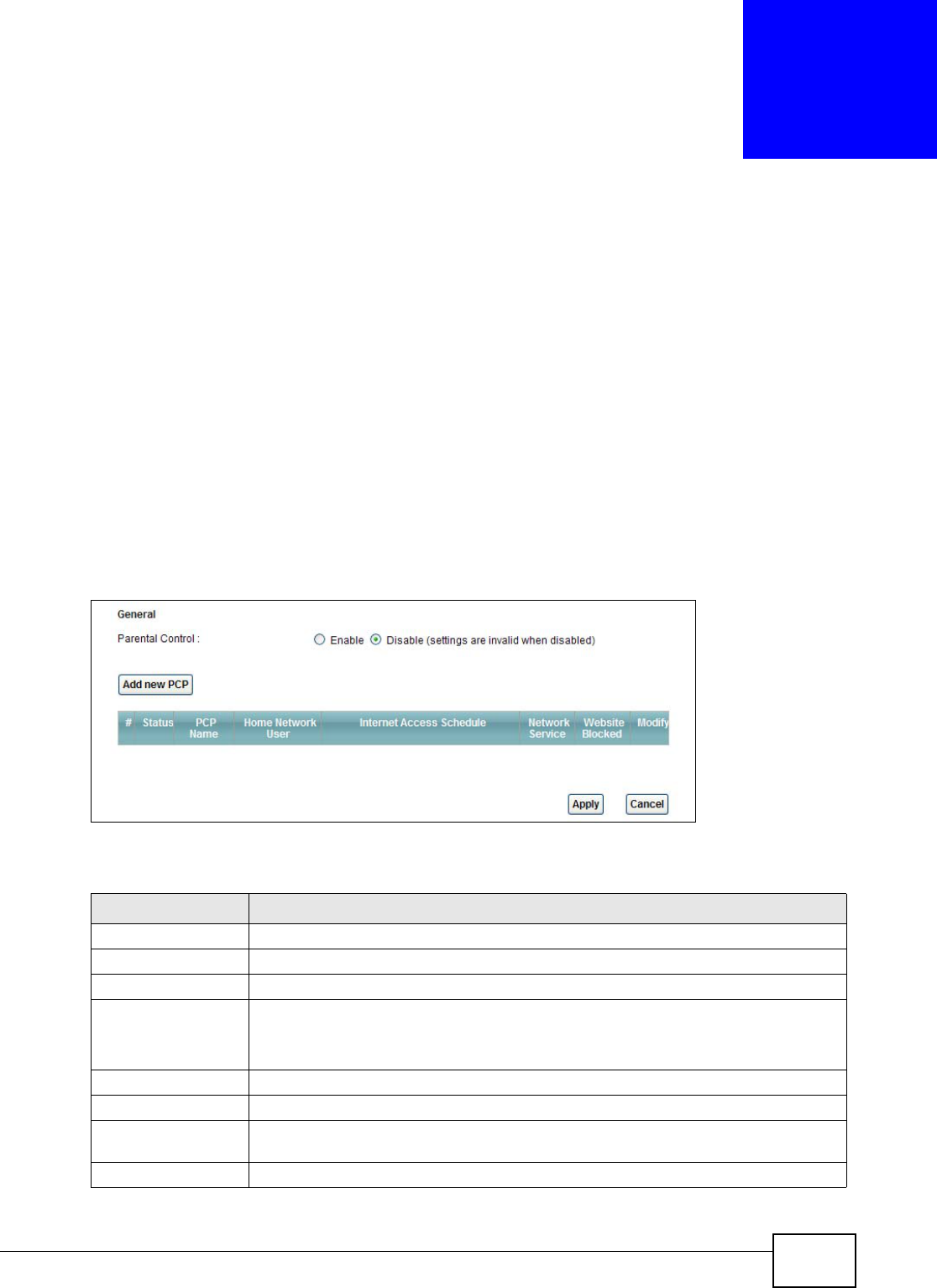
16.2 The Parental Control Screen
Use this screen to enable parental control, view the parental control rules and schedules.
Click Security > Parental Control to open the following screen.
Figure 97 Security > Parental Control
The following table describes the fields in this screen.
Table 72 Security > Parental Control
LABEL DESCRIPTION
Parental Control Use this field to activate or deactivate parental control.
Add new PCP Click this to create a new parental control rule.
# This is the index number of the rule.
Status This indicates whether the rule is active or not.
A yellow bulb signifies that this rule is active. A gray bulb signifies that this rule is not
active.
PCP Name This shows the name of the rule.
Home Network User This shows the MAC address of the LAN user’s computer to which this rule applies.
Internet Access
Schedule
This shows the day(s) and time on which parental control is enabled.
Network Service This shows whether the network service is configured. If not, None will be shown.
Chapter 16 Parental Control
AMG1312-T Series User’s Guide 187
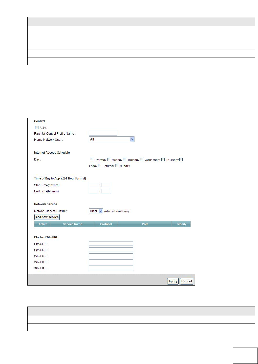
16.2.1 Add/Edit Parental Control Rule
Click Add new PCP in the Parental Control screen to add a new rule or click the Edit icon next to
an existing rule to edit it. Use this screen to configure a restricted access schedule and/or URL
filtering settings to block the users on your network from accessing certain web sites.
Figure 98 Add/Edit Parental Control Rule
The following table describes the fields in this screen.
Website Blocked This shows whether the website block is configured. If not, None will be shown.
Modify Click the Edit icon to go to the screen where you can edit the rule.
Click the Delete icon to delete an existing rule.
Apply Click Apply to save your changes.
Cancel Click Cancel to restore your previously saved settings.
Table 72 Security > Parental Control (continued)
LABEL DESCRIPTION
Table 73 Parental Control: Add/Edit
LABEL DESCRIPTION
General
Active Select the checkbox to activate this parental control rule.
Chapter 16 Parental Control
AMG1312-T Series User’s Guide
188
Parental Control
Profile Name
Enter a descriptive name for the rule.
Home Network User Select the LAN user that you want to apply this rule to from the drop-down list box. If
you select Custom, enter the LAN user’s MAC address. If you select All, the rule
applies to all LAN users.
Internet Access Schedule
Day Select check boxes for the days that you want the AMG1312-T Series to perform
parental control.
Time of Day to Apply Enter the starting and ending time that the LAN user is allowed access.
Network Service
Network Service
Setting
If you select Block, the AMG1312-T Series prohibits the users from viewing the Web
sites with the URLs listed below.
If you select Access, the AMG1312-T Series blocks access to all URLs except ones
listed below.
Add new service Click this to show a screen in which you can add a new service rule. You can configure
the Service Name, Protocol, and Name of the new rule.
Active This shows whether a configured service is activated or not.
Service Name This shows the name of the rule.
Protocol This shows the protocol of the rule.
Port This shows the port of the rule.
Modify Click the Edit icon to go to the screen where you can edit the rule.
Click the Delete icon to delete an existing rule.
Blocked Site/URL Enter the URL of web sites or URL keywords to which the AMG1312-T Series blocks
access.
Apply Click Apply to save your changes.
Cancel Click Cancel to exit this screen without saving.
Table 73 Parental Control: Add/Edit (continued)
LABEL DESCRIPTION

AMG1312-T Series User’s Guide 189
CHAPTER 17
Certificate
17.1 Overview
The AMG1312-T Series can use certificates (also called digital IDs) to authenticate users.
Certificates are based on public-private key pairs. A certificate contains the certificate owner’s
identity and public key. Certificates provide a way to exchange public keys for use in authentication.
17.1.1 What You Can Do in this Chapter
•Use the Local Certificates screen to view and import the AMG1312-T Series’s CA-signed
certificates (Section 17.3 on page 189).
•The Trusted CA screen lets you save the certificates of trusted CAs to the AMG1312-T Series
(Section 17.4 on page 191).
17.2 What You Need to Know
The following terms and concepts may help as you read through this chapter.
Certification Authority
A Certification Authority (CA) issues certificates and guarantees the identity of each certificate
owner. There are commercial certification authorities like CyberTrust or VeriSign and government
certification authorities. The certification authority uses its private key to sign certificates. Anyone
can then use the certification authority's public key to verify the certificates. You can use the
AMG1312-T Series to generate certification requests that contain identifying information and public
keys and then send the certification requests to a certification authority.
Certificate File Format
The certification authority certificate that you want to import has to be in one of these file formats:
• PEM (Base-64) encoded X.509: This Privacy Enhanced Mail format uses 64 ASCII characters to
convert a binary X.509 certificate into a printable form.
17.3 Local Certificates
Use this screen to view the AMG1312-T Series’s summary list of certificates and certification
requests. You can import the following certificates to your AMG1312-T Series:
Chapter 17 Certificate
AMG1312-T Series User’s Guide
190
• Web Server - This certificate secures HTTP connections.
• SSH - This certificate secures remote connections.
Click Security > Certificates to open the Local Certificates screen.
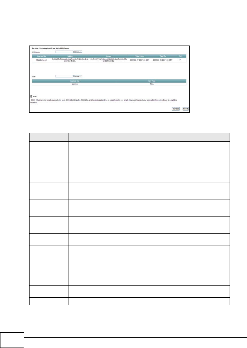
Figure 99 Security > Certificates > Local Certificates
The following table describes the labels in this screen.
Table 74 Security > Certificates > Local Certificates
LABEL DESCRIPTION
WebServer Click Browse... to find the certificate file you want to upload.
Current File This field displays the name used to identify this certificate. It is recommended
that you give each certificate a unique name.
Subject This field displays identifying information about the certificate’s owner, such as
CN (Common Name), OU (Organizational Unit or department), O (Organization
or company) and C (Country). It is recommended that each certificate have
unique subject information.
Issuer This field displays identifying information about the certificate’s issuing
certification authority, such as a common name, organizational unit or
department, organization or company and country.
Valid From This field displays the date that the certificate becomes applicable. The text
displays in red and includes a Not Yet Valid! message if the certificate has not
yet become applicable.
Valid To This field displays the date that the certificate expires. The text displays in red
and includes an Expiring! or Expired! message if the certificate is about to
expire or has already expired.
Cert Click this button and then Save in the File Download screen. The Save As
screen opens, browse to the location that you want to use and click Save.
SSH Type in the location of the SSH certificate file you want to upload in this field or
click Browse to find it.
Current File This field displays the name used to identify this certificate. It is recommended
that you give each certificate a unique name.
Key Type This field applies to the SSH certificate.
This shows the file format of the current certificate.
Replace Click this to replace the certificate(s) and save your changes back to the
AMG1312-T Series.
Reset Click this to clear your settings.
Chapter 17 Certificate
AMG1312-T Series User’s Guide 191
17.4 The Trusted CA Screen
Use this screen to view a summary list of certificates of the certification authorities that you have
set the AMG1312-T Series to accept as trusted. The AMG1312-T Series accepts any valid certificate
signed by a certification authority on this list as being trustworthy; thus you do not need to import
any certificate that is signed by one of these certification authorities.
Click Security > Certificates > Trusted CA to open the Trusted CA screen.
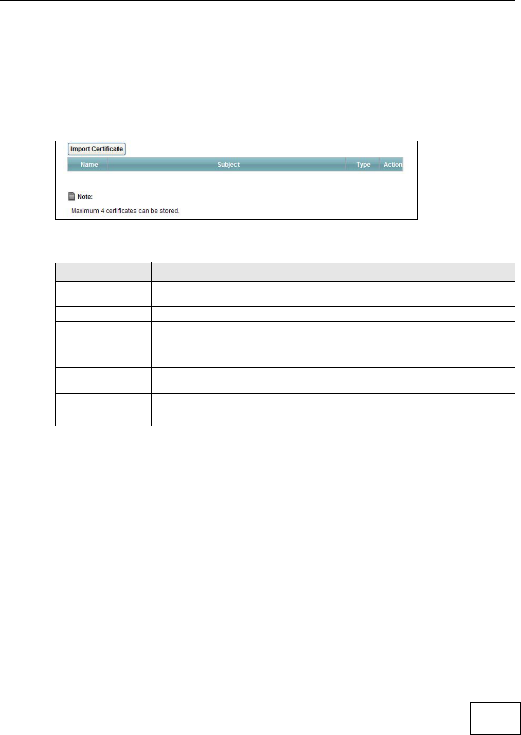
Figure 100 Security > Certificates > Trusted CA
The following table describes the fields in this screen.
17.5 Trusted CA Import
Click Import Certificate in the Trusted CA screen to open the Import Certificate screen. You
can save a trusted certification authority’s certificate to the AMG1312-T Series.
Table 75 Security > Certificates > Trusted CA
LABEL DESCRIPTION
Import Certificate Click this button to open a screen where you can save the certificate of a certification
authority that you trust to the AMG1312-T Series.
Name This field displays the name used to identify this certificate.
Subject This field displays information that identifies the owner of the certificate, such as
Common Name (CN), OU (Organizational Unit or department), Organization (O), State
(ST) and Country (C). It is recommended that each certificate have unique subject
information.
Type This field displays general information about the certificate. ca means that a
Certification Authority signed the certificate.
Action Click View to open a screen with an in-depth list of information about the certificate.
Click Remove to delete the certificate.

Chapter 17 Certificate
AMG1312-T Series User’s Guide
192
Note: You must remove any spaces from the certificate’s filename before you can import
the certificate.
Figure 101 Trusted CA > Import
The following table describes the labels in this screen.
17.6 View Certificate
Use this screen to view in-depth information about the certification authority’s certificate, change
the certificate’s name and set whether or not you want the AMG1312-T Series to check a
certification authority’s list of revoked certificates before trusting a certificate issued by the
certification authority.
Table 76 Security > Certificates > Trusted CA > Import
LABEL DESCRIPTION
Certificate File
Path
Type in the location of the file you want to upload in this field or click Browse to
find it.
Browse Click Browse to find the certificate file you want to upload.
Apply Click Apply to save the certificate on the AMG1312-T Series.
Back Click Back to return to the previous screen.
Chapter 17 Certificate
AMG1312-T Series User’s Guide 193
Click Security > Certificates > Trusted CA to open the Trusted CA screen. Click the View icon
to open the View Certificate screen.
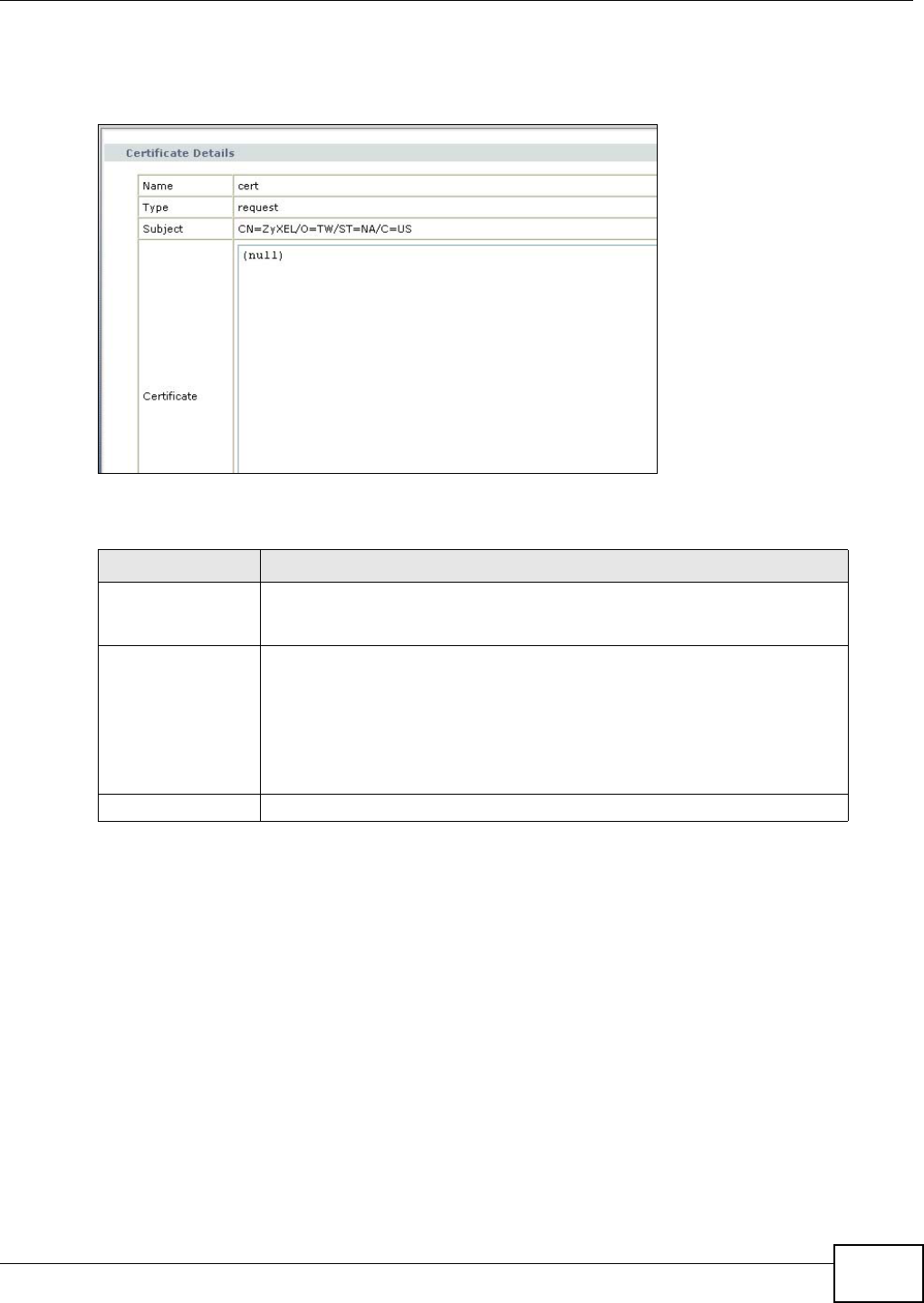
Figure 102 Trusted CA: View
The following table describes the labels in this screen.
Table 77 Trusted CA: View
LABEL DESCRIPTION
Certificate Name This field displays the identifying name of this certificate. If you want to
change the name, type up to 31 characters to identify this key certificate. You
may use any character (not including spaces).
Certificate Detail This read-only text box displays the certificate or certification request in
Privacy Enhanced Mail (PEM) format. PEM uses 64 ASCII characters to convert
the binary certificate into a printable form.
You can copy and paste the certificate into an e-mail to send to friends or
colleagues or you can copy and paste the certificate into a text editor and save
the file on a management computer for later distribution (via floppy disk for
example).
Back Click this to return to the previous screen.

AMG1312-T Series User’s Guide 194
CHAPTER 18
Logs
18.1 Overview
The web configurator allows you to choose which categories of events and/or alerts to have the
AMG1312-T Series log and then display the logs or have the AMG1312-T Series send them to an
administrator (as e-mail) or to a syslog server.
18.1.1 What You Can Do in this Chapter
•Use the Log screen to see the system logs for the categories that you select (Section 18.2 on
page 195).
18.1.2 What You Need To Know
The following terms and concepts may help as you read this chapter.
Alerts and Logs
An alert is a type of log that warrants more serious attention. They include system errors, attacks
(access control) and attempted access to blocked web sites. Some categories such as System
Errors consist of both logs and alerts. You may differentiate them by their color in the View Log
screen. Alerts display in red and logs display in black.
Syslog Overview
The syslog protocol allows devices to send event notification messages across an IP network to
syslog servers that collect the event messages. A syslog-enabled device can generate a syslog
message and send it to a syslog server.
Syslog is defined in RFC 3164. The RFC defines the packet format, content and system log related
information of syslog messages. Each syslog message has a facility and severity level. The syslog
facility identifies a file in the syslog server. Refer to the documentation of your syslog program for
details. The following table describes the syslog severity levels.
Table 78 Syslog Severity Levels
CODE SEVERITY
0 Emergency: The system is unusable.
1 Alert: Action must be taken immediately.
2 Critical: The system condition is critical.
3 Error: There is an error condition on the system.
4 Warning: There is a warning condition on the system.
5 Notice: There is a normal but significant condition on the system.
Chapter 18 Logs
AMG1312-T Series User’s Guide 195
18.2 The System Log Screen
Click System Monitor > Log to open the System Log screen. Use the System Log screen to see
the system logs for the categories that you select in the upper left drop-down list box.
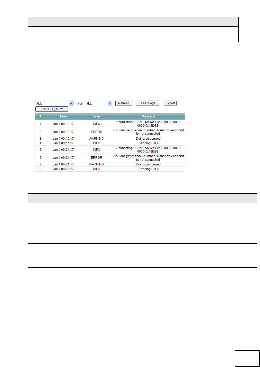
Figure 103 System Monitor > Log > System Log
The following table describes the fields in this screen.
6 Informational: The syslog contains an informational message.
7 Debug: The message is intended for debug-level purposes.
Table 78 Syslog Severity Levels (continued)
CODE SEVERITY
Table 79 System Monitor > Log > System Log
LABEL DESCRIPTION
Level Select a severity level from the drop-down list box. This filters search results according to
the severity level you have selected. When you select a severity, the AMG1312-T Series
searches through all logs of that severity or higher.
Refresh Click this to renew the log screen.
Clear Logs Click this to delete all the logs.
Export Click this to download logs to a file on your computer.
Email Log Now Click this to send logs to a specified e-mail address.
#This field is a sequential value and is not associated with a specific entry.
Time This field displays the time the log was recorded.
Level This field displays the severity level of the logs that the device is to send to this syslog
server.
Message This field states the reason for the log.
AMG1312-T Series User’s Guide 196
CHAPTER 19
Traffic Status
19.1 Overview
Use the Traffic Status screens to look at network traffic status and statistics of the WAN, LAN
interfaces and NAT.
19.1.1 What You Can Do in this Chapter
•Use the WAN screen to view the WAN traffic statistics (Section 19.2 on page 196).
•Use the LAN screen to view the LAN traffic statistics (Section 19.3 on page 197).
•Use the NAT screen to view the NAT status of the AMG1312-T Series’s client(s) (Section 19.4 on
page 198).
19.2 The WAN Status Screen
Click System Monitor > Traffic Status to open the WAN screen. You can view the WAN traffic
statistics in this screen.
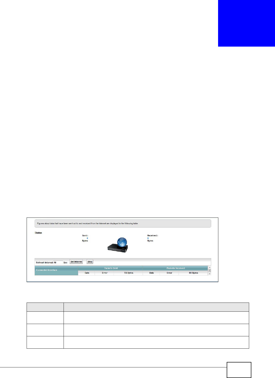
Figure 104 System Monitor > Traffic Status > WAN
The following table describes the fields in this screen.
Table 80 System Monitor > Traffic Status > WAN
LABEL DESCRIPTION
Status This shows the number of bytes received and sent through the WAN interface of the
AMG1312-T Series.
Refresh Interval Select how often you want the AMG1312-T Series to update this screen from the drop-down
list box.
Connected
Interface
This shows the name of the WAN interface that is currently connected.
Chapter 19 Traffic Status
AMG1312-T Series User’s Guide 197
19.3 The LAN Status Screen
Click System Monitor > Traffic Status > LAN to open the following screen. You can view the LAN
traffic statistics in this screen.
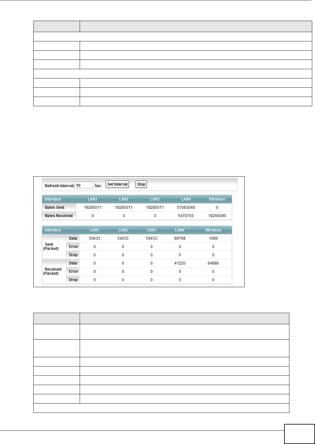
Figure 105 System Monitor > Traffic Status > LAN
The following table describes the fields in this screen.
Packets Sent
Data This indicates the number of transmitted packets on this interface.
Error This indicates the number of frames with errors transmitted on this interface.
Drop This indicates the number of outgoing packets dropped on this interface.
Packets Received
Data This indicates the number of received packets on this interface.
Error This indicates the number of frames with errors received on this interface.
Drop This indicates the number of received packets dropped on this interface.
Table 80 System Monitor > Traffic Status > WAN (continued)
LABEL DESCRIPTION
Table 81 System Monitor > Traffic Status > LAN
LABEL DESCRIPTION
Refresh
Interval(s)
Select how often you want the AMG1312-T Series to update this screen from the
drop-down list box.
Set Interval Click this button to apply the new poll interval you entered in the Refresh
Interval field.
Stop Click Stop to stop refreshing statistics.
Interface This shows the LAN or WLAN interface.
Bytes Sent This indicates the number of bytes transmitted on this interface.
Bytes Received This indicates the number of bytes received on this interface.
Interface This shows the LAN or WLAN interface.
Sent (Packet)
Chapter 19 Traffic Status
AMG1312-T Series User’s Guide
198
19.4 The NAT Screen
Click System Monitor > Traffic Status > NAT to open the following screen. You can view the NAT
status of the AMG1312-T Series’s client(s) in this screen.
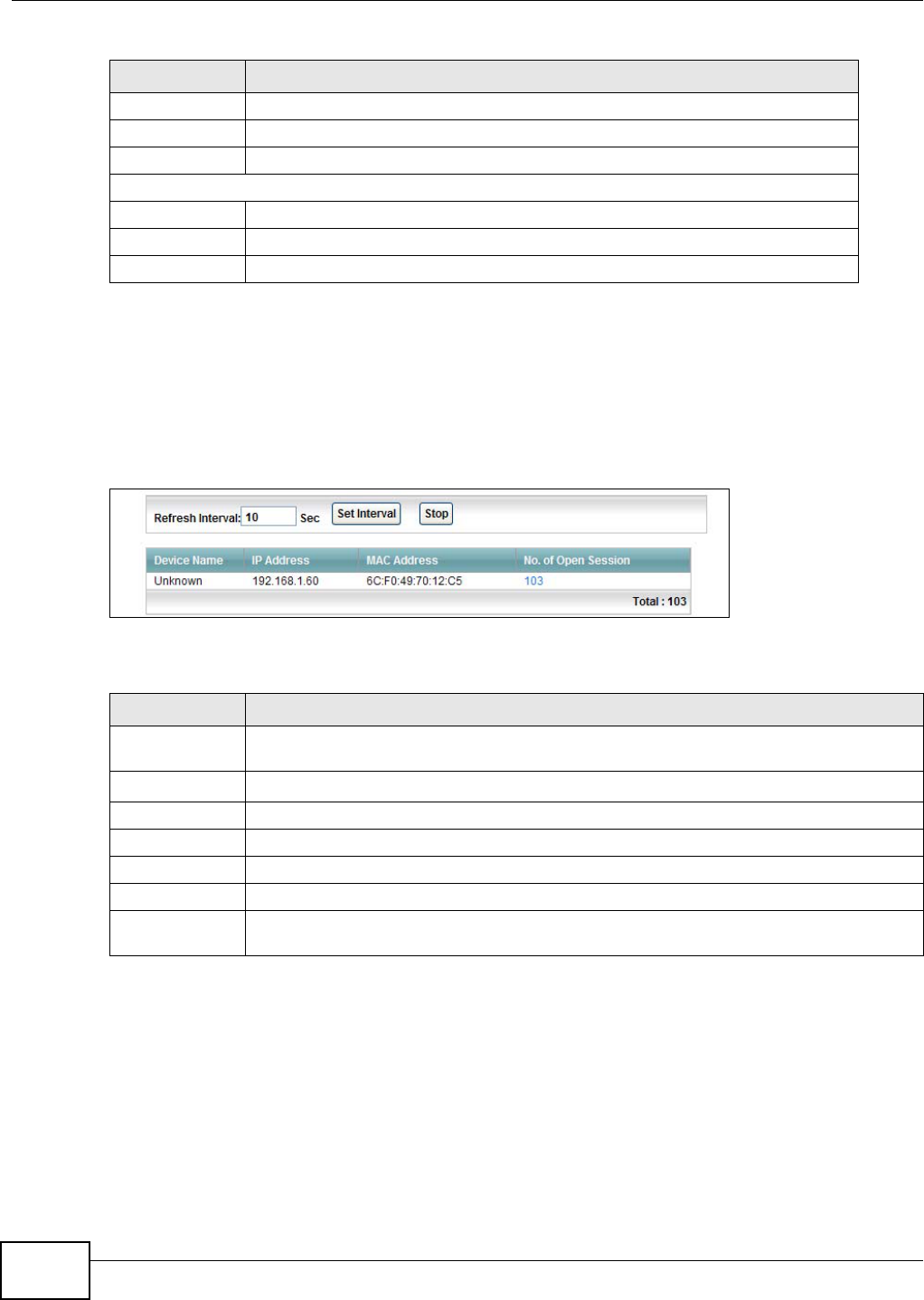
Figure 106 System Monitor > Traffic Status > NAT
The following table describes the fields in this screen.
Data This indicates the number of transmitted packets on this interface.
Error This indicates the number of frames with errors transmitted on this interface.
Drop This indicates the number of outgoing packets dropped on this interface.
Received (Packet)
Data This indicates the number of received packets on this interface.
Error This indicates the number of frames with errors received on this interface.
Drop This indicates the number of received packets dropped on this interface.
Table 81 System Monitor > Traffic Status > LAN (continued)
LABEL DESCRIPTION
Table 82 System Monitor > Traffic Status > NAT
LABEL DESCRIPTION
Refresh Interval Select how often you want the AMG1312-T Series to update this screen from the drop-
down list box.
Set Interval Click this button to apply the new poll interval you entered in the Refresh Interval field.
Stop Click Stop to stop refreshing statistics.
Device Name This shows the name of the client.
IP Address This shows the IP address of the client.
MAC Address This shows the MAC address of the client.
No. of Open
Session
This shows the number of NAT sessions used by the client.
AMG1312-T Series User’s Guide 199
CHAPTER 20
User Account
20.1 Overview
You can configure system password for different user accounts in the User Account screen.
20.2 The User Account Screen
Use the User Account screen to configure system password.
Click Maintenance > User Account to open the following screen.
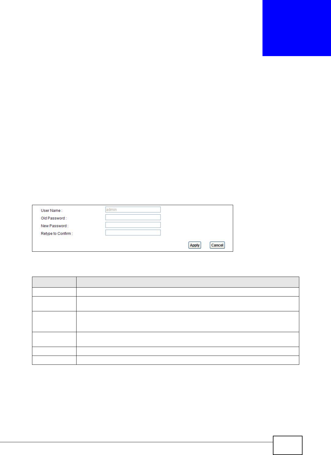
Figure 107 Maintenance > User Account
The following table describes the labels in this screen.
Table 83 Maintenance > User Account
LABEL DESCRIPTION
User Name You can configure the password for the Power User and Admin accounts.
Old Password Type the default password or the existing password you use to access the system in this
field.
New Password Type your new system password (up to 30 characters). Note that as you type a password,
the screen displays a (*) for each character you type. After you change the password, use
the new password to access the AMG1312-T Series.
Retype to
Confirm
Type the new password again for confirmation.
Apply Click Apply to save your changes.
Cancel Click Cancel to restore your previously saved settings.
AMG1312-T Series User’s Guide 200
CHAPTER 21
TR-069 Client
21.1 Overview
The AMG1312-T Series supports TR-069 Amendment 1 (CPE WAN Management Protocol Release
2.0) and TR-069 Amendment 2 (CPE WAN Management Protocol v1.1, Release 3.0).
TR-069 is a protocol that defines how your AMG1312-T Series (ZD) can be managed via a
management server (MS) such as ZyXEL’s Vantage Access.
Figure 108 LAN and WAN
An administrator can use a management server to remotely set up the AMG1312-T Series, modify
settings, perform firmware upgrades as well as monitor and diagnose the AMG1312-T Series.
In order to use CWMP, you need to configure the following steps:
1Activate CWMP
2Specify the URL, username and password.
3Activate periodic inform and specify an interval value.
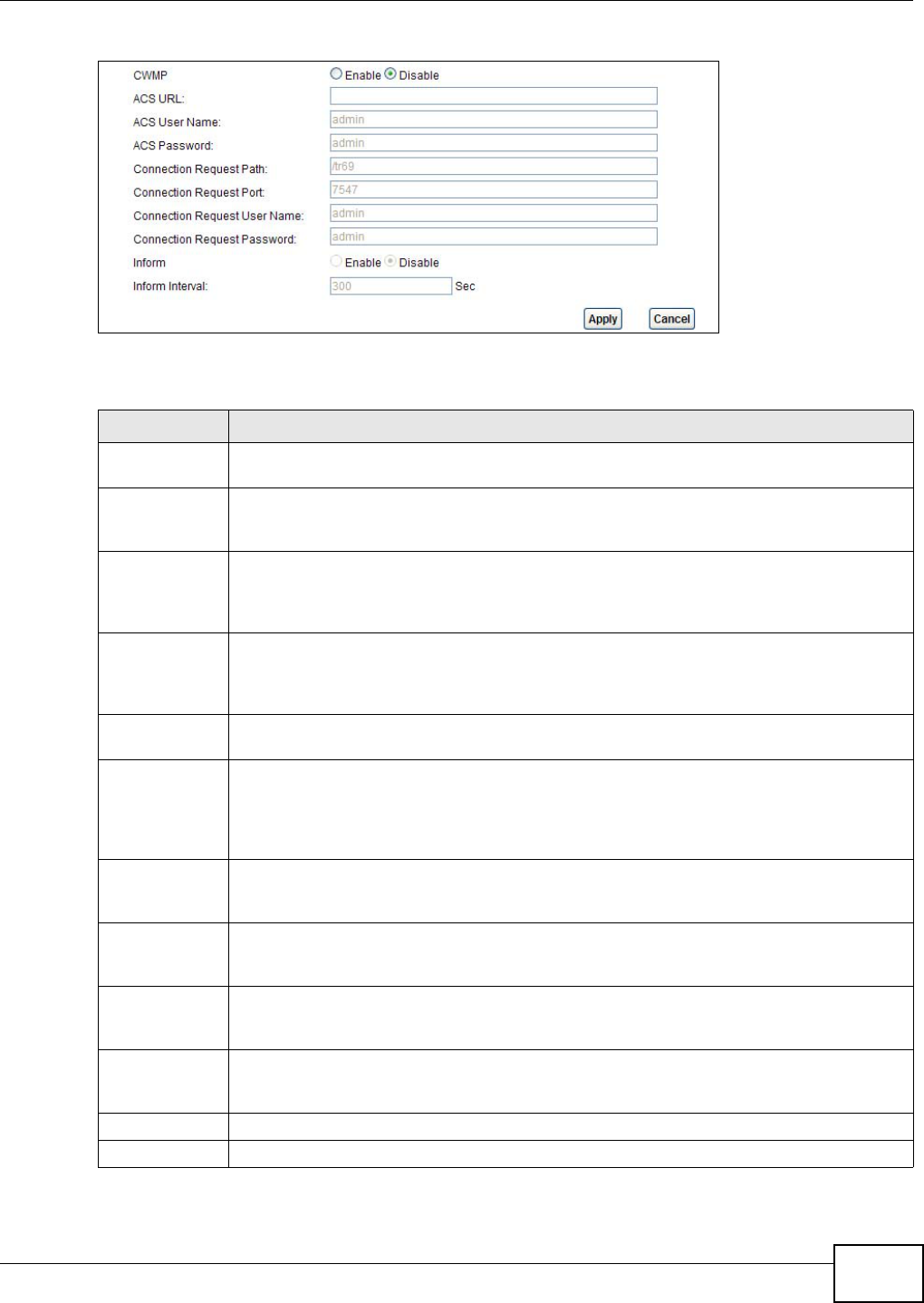
21.2 The TR-069 Client Screen
Use this screen to configure your AMG1312-T Series to be managed by a management server. Click
Maintenance > TR-069 Client to display the following screen.
MSZD
Chapter 21 TR-069 Client
AMG1312-T Series User’s Guide 201
Figure 109 Maintenance > TR-069 Client
The following table describes the fields in this screen.
Table 84 Maintenance > TR-069 Client
LINK DESCRIPTION
CWMP Select Enable to allow the AMG1312-T Series to be managed by a management server or
select Disable to not allow the AMG1312-T Series to be managed by a management server.
ACS URL Type the IP address or domain name of the management server. If the AMG1312-T Series is
behind a NAT router that assigns it a private IP address, you will have to configure a NAT
port forwarding rule on the NAT router.
ACS User Name The user name is used to authenticate the AMG1312-T Series when making a connection to
the management server. This user name on the management server and the AMG1312-T
Series must be the same. Type a user name of up to 255 printable characters found on an
English-language keyboard. Spaces and characters such as @#$%^&*()_+ are allowed.
ACS Password The password is used to authenticate the AMG1312-T Series when making a connection to
the management server. This password on the management server and the AMG1312-T
Series must be the same. Type a password of up to 255 printable characters found on an
English-language keyboard.
Connection
Request Path
Type the IP address or domain name of the AMG1312-T Series. The management server
uses this path to verify the AMG1312-T Series.
Connection
Request Port
The default port for access to the AMG1312-T Series from the management server is port
7547. If you change it, make sure it does not conflict with another port on your network and
it is recommended to use a port number above 1024 (not a commonly used port). The
management server should use this port to connect to the AMG1312-T Series. You may
need to alter your NAT port forwarding rules if they were already configured.
Connection
Request
UserName
The user name is used to authenticate the management server when connecting to the
AMG1312-T Series. Type a user name of up to 255 printable characters found on an English-
language keyboard. Spaces and characters such as @#$%^&*()_+ are allowed.
Connection
Request
Password
The password is used to authenticate the management server when connecting to the
AMG1312-T Series. Type a password of up to 255 printable characters found on an English-
language keyboard. Spaces are not allowed.
Inform Select Enable to have the AMG1312-T Series periodically send information to the
management server (recommended if CWMP is enabled) or select Disable to not have the
AMG1312-T Series periodically send information to the management server
Inform Interval The interval is the duration in seconds for which the AMG1312-T Series must attempt to
connect with the management server to send information and check for configuration
updates. Enter a value between 1 and 86400 seconds.
Apply Click this to save your changes.
Cancel Click this to restore your previously saved settings.
AMG1312-T Series User’s Guide 202
CHAPTER 22
System Settings
22.1 Overview
This chapter shows you how to configure system related settings, such as system time, password,
name, the domain name and the inactivity timeout interval.
22.1.1 What You Can Do in the System Settings Screens
•Use the System screen (Section 22.2 on page 202) to configure system settings.
•Use the Time Setting screen (Section 22.3 on page 202) to set the system time.
22.2 The System Screen
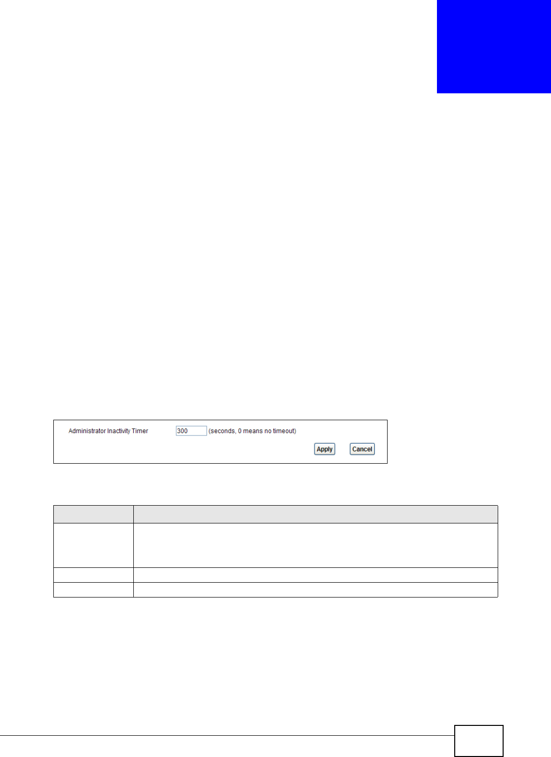
Use this screen to configure system admin password.
Click Maintenance > System to open the screen as shown.
Figure 110 Maintenance > System
The following table describes the labels in this screen.
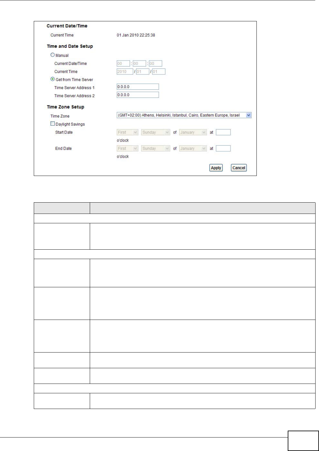
22.3 The Time Screen
Use this screen to configure the AMG1312-T Series’s time based on your local time zone. To change
your AMG1312-T Series’s time and date, click Maintenance > System > Time Setting. The
screen appears as shown.
Table 85 Maintenance > System
LABEL DESCRIPTION
Administrator
Inactivity Timer
Type how many seconds a management session (either via the web configurator) can be
left idle before the session times out and you have to log in again. Very long idle timeouts
may have security risks. A value of "0" means a management session never times out, no
matter how long it has been left idle (not recommended).
Apply Click this to save your changes.
Cancel Click this to restore your previously saved settings.
Chapter 22 System Settings
AMG1312-T Series User’s Guide 203
Figure 111 Maintenance > System > Time Setting
The following table describes the fields in this screen.
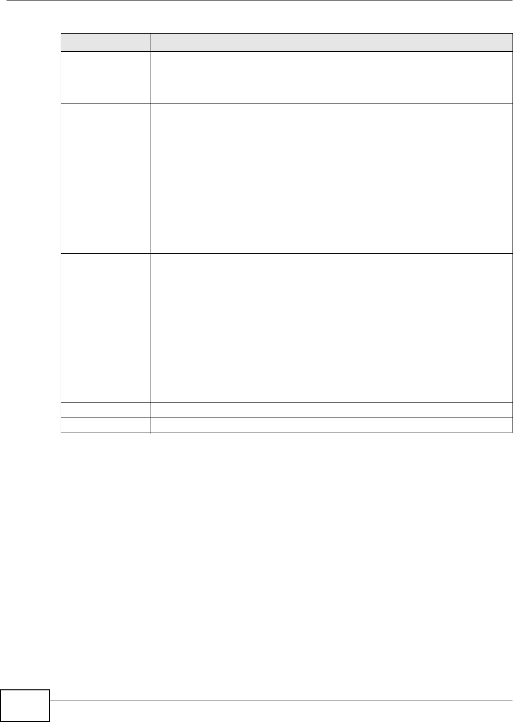
Table 86 Maintenance > System > Time
LABEL DESCRIPTION
Current Date/Time
Current Time This field displays the time and date of your AMG1312-T Series.
Each time you reload this page, the AMG1312-T Series synchronizes the time and date
with the time server.
Time and Date Setup
Manual Select this radio button to enter the time and date manually. If you configure a new
time and date, Time Zone and Daylight Saving at the same time, the new time and date
you entered has priority and the Time Zone and Daylight Saving settings do not affect
it.
Current Date/Time This field displays the last updated time (in hh:mm:ss format) from the time server or
the last time configured manually.
When you set Time and Date Setup to Manual, enter the new time in this field and
then click Apply.
Current Time This field displays the last updated date (in yyyy/mm/dd format) from the time server
or the last date configured manually.
When you set Time and Date Setup to Manual, enter the new date in this field and
then click Apply.
Get from Time
Server
Select this radio button to have the AMG1312-T Series get the time and date from the
time server you specified below.
Time Server
Address 1/2
Enter the IP address or URL (up to 20 extended ASCII characters in length) of your time
server. Check with your ISP/network administrator if you are unsure of this information.
Time Zone Setup
Time Zone Choose the time zone of your location. This will set the time difference between your
time zone and Greenwich Mean Time (GMT).
Chapter 22 System Settings
AMG1312-T Series User’s Guide
204
Daylight Savings Daylight saving is a period from late spring to early fall when many countries set their
clocks ahead of normal local time by one hour to give more daytime light in the
evening.
Select this option if you use Daylight Saving Time.
Start Date Configure the day and time when Daylight Saving Time starts if you selected Enable
Daylight Saving. The o'clock field uses the 24 hour format. Here are a couple of
examples:
Daylight Saving Time starts in most parts of the United States on the second Sunday of
March. Each time zone in the United States starts using Daylight Saving Time at 2 A.M.
local time. So in the United States you would select Second, Sunday, March and type
2 in the o'clock field.
Daylight Saving Time starts in the European Union on the last Sunday of March. All of
the time zones in the European Union start using Daylight Saving Time at the same
moment (1 A.M. GMT or UTC). So in the European Union you would select Last,
Sunday, March. The time you type in the o'clock field depends on your time zone. In
Germany for instance, you would type 2 because Germany's time zone is one hour
ahead of GMT or UTC (GMT+1).
End Date Configure the day and time when Daylight Saving Time ends if you selected Enable
Daylight Saving. The o'clock field uses the 24 hour format. Here are a couple of
examples:
Daylight Saving Time ends in the United States on the first Sunday of November. Each
time zone in the United States stops using Daylight Saving Time at 2 A.M. local time. So
in the United States you would select First, Sunday, November and type 2 in the
o'clock field.
Daylight Saving Time ends in the European Union on the last Sunday of October. All of
the time zones in the European Union stop using Daylight Saving Time at the same
moment (1 A.M. GMT or UTC). So in the European Union you would select Last,
Sunday, October. The time you type in the o'clock field depends on your time zone.
In Germany for instance, you would type 2 because Germany's time zone is one hour
ahead of GMT or UTC (GMT+1).
Apply Click this to save your changes.
Cancel Click this to restore your previously saved settings.
Table 86 Maintenance > System > Time (continued)
LABEL DESCRIPTION
AMG1312-T Series User’s Guide 205
CHAPTER 23
Firmware Upgrade
23.1 Overview
This chapter explains how to upload new firmware to your AMG1312-T Series. You can download
new firmware releases from your nearest ZyXEL FTP site (or www.zyxel.com) to use to upgrade
your device’s performance.
Only use firmware for your device’s specific model. Refer to the label on
the bottom of your AMG1312-T Series.
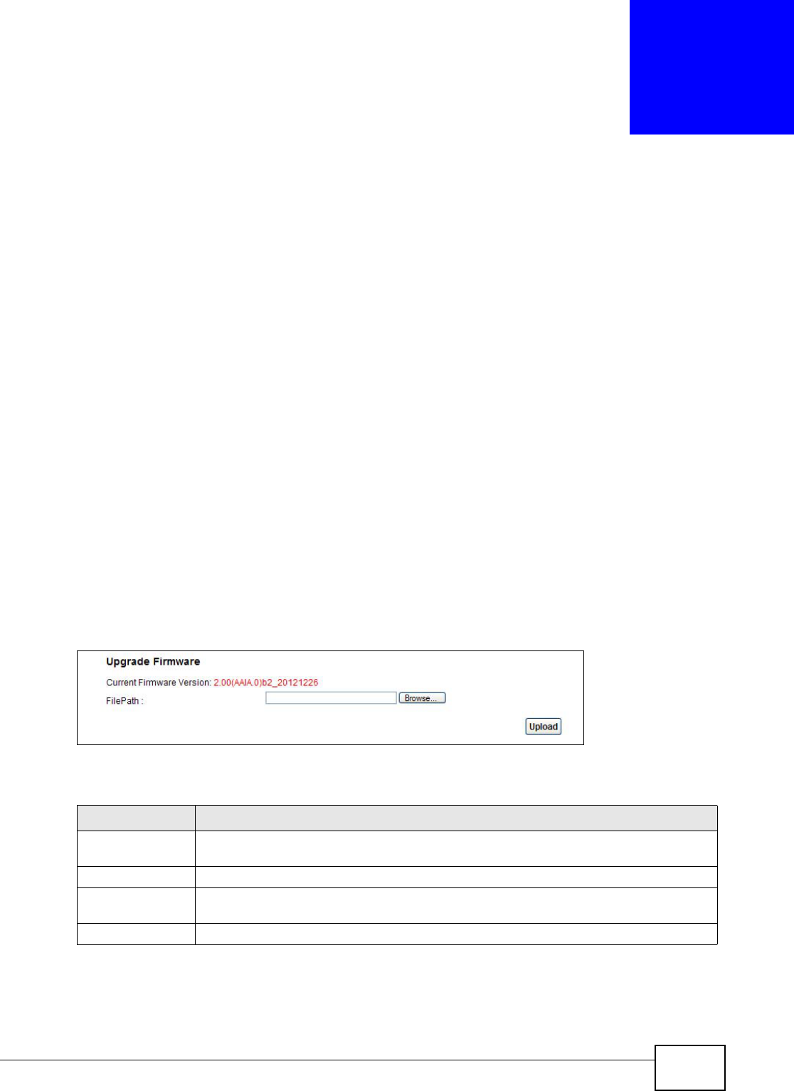
23.2 The Firmware Screen
Click Maintenance > Firmware Upgrade to open the following screen. The upload process uses
HTTP (Hypertext Transfer Protocol) and may take up to two minutes. After a successful upload, the
system will reboot.
Do NOT turn off the AMG1312-T Series while firmware upload is in
progress!
Figure 112 Maintenance > Firmware Upgrade
The following table describes the labels in this screen.
After you see the firmware updating screen, wait two minutes before logging into the AMG1312-T
Series again.
Table 87 Maintenance > Firmware Upgrade
LABEL DESCRIPTION
Current Firmware
Version
This is the present Firmware version.
File Path Type in the location of the file you want to upload in this field or click Browse... to find it.
Browse... Click this to find the .bin file you want to upload. Remember that you must decompress
compressed (.zip) files before you can upload them.
Upload Click this to begin the upload process. This process may take up to two minutes.
Chapter 23 Firmware Upgrade
AMG1312-T Series User’s Guide
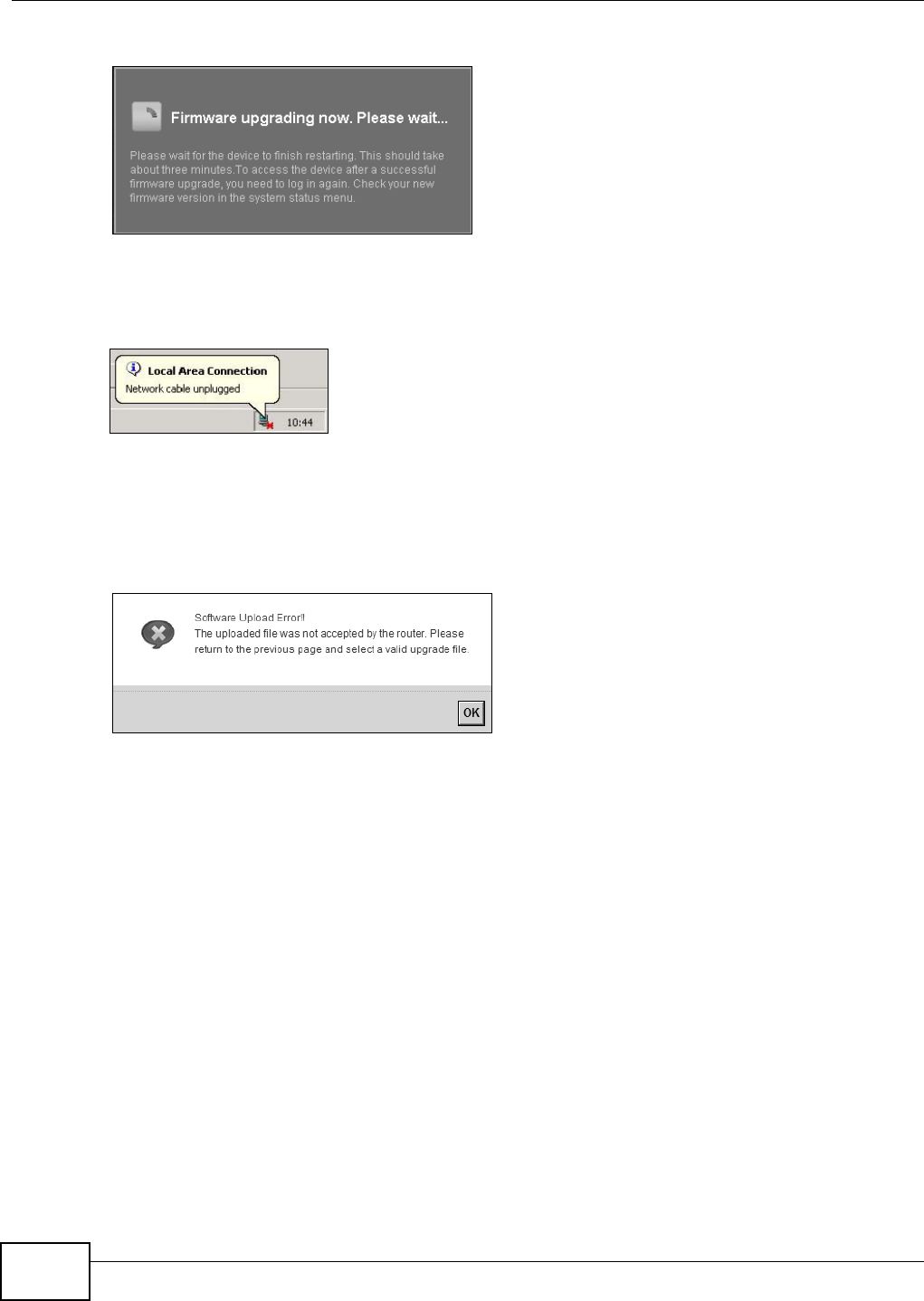
206
Figure 113 Firmware Uploading
The AMG1312-T Series automatically restarts in this time causing a temporary network disconnect.
In some operating systems, you may see the following icon on your desktop.
Figure 114 Network Temporarily Disconnected
After two minutes, log in again and check your new firmware version in the Status screen.
If the upload was not successful, an error screen will appear. Click OK to go back to the Firmware
Upgrade screen.
Figure 115 Error Message
AMG1312-T Series User’s Guide 207
CHAPTER 24
Backup/Restore
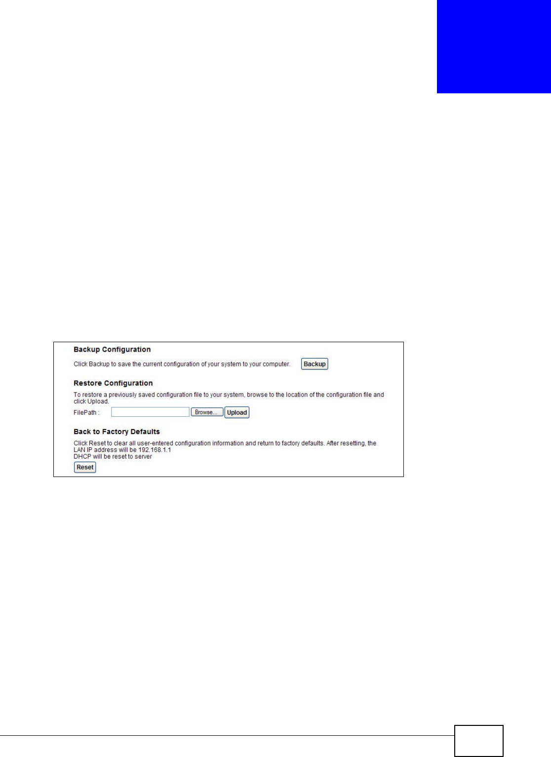
24.1 Overview
The Backup/Restore screen allows you to backup and restore device configurations. You can also
reset your device settings back to the factory default.
24.2 The Backup/Restore Screen
Click Maintenance > Backup/Restore. Information related to factory defaults, backup
configuration, and restoring configuration appears in this screen, as shown next.
Figure 116 Maintenance > Backup/Restore
Backup Configuration
Backup Configuration allows you to back up (save) the AMG1312-T Series’s current configuration to
a file on your computer. Once your AMG1312-T Series is configured and functioning properly, it is
highly recommended that you back up your configuration file before making configuration changes.
The backup configuration file will be useful in case you need to return to your previous settings.
Click Backup to save the AMG1312-T Series’s current configuration to your computer.
Chapter 24 Backup/Restore
AMG1312-T Series User’s Guide
208
Restore Configuration
Restore Configuration allows you to upload a new or previously saved configuration file from your
computer to your AMG1312-T Series.
Do not turn off the AMG1312-T Series while configuration file upload is in
progress.
After the AMG1312-T Series configuration has been restored successfully, the login screen appears.
Login again to restart the AMG1312-T Series.
The AMG1312-T Series automatically restarts in this time causing a temporary network disconnect.
In some operating systems, you may see the following icon on your desktop.
Figure 117 Network Temporarily Disconnected
If you restore the default configuration, you may need to change the IP address of your computer
to be in the same subnet as that of the default device IP address (192.168.1.1). See Appendix A on
page 229 for details on how to set up your computer’s IP address.
If the upload was not successful, an error screen will appear. Click OK to go back to the
Configuration screen.
Reset to Factory Defaults
Click the Reset button to clear all user-entered configuration information and return the AMG1312-
T Series to its factory defaults. The following warning screen appears.
Figure 118 Reset Warning Message
Wait until the AMG1312-T Series’s login screen appears. You can also press the RESET button on
the rear panel to reset the factory defaults of your AMG1312-T Series. Refer to Section 1.7 on page
18 for more information on the RESET button.
Table 88 Restore Configuration
LABEL DESCRIPTION
File Path Type in the location of the file you want to upload in this field or click Browse... to find it.
Browse... Click this to find the file you want to upload. Remember that you must decompress
compressed (.ZIP) files before you can upload them.
Upload Click this to begin the upload process.
Reset Click this to reset your device settings back to the factory default.
Chapter 24 Backup/Restore
AMG1312-T Series User’s Guide 209
24.3 The Reboot Screen
System restart allows you to reboot the AMG1312-T Series remotely without turning the power off.
You may need to do this if the AMG1312-T Series hangs, for example.
Click Maintenance > Reboot. Click the Reboot button to have the AMG1312-T Series reboot. This
does not affect the AMG1312-T Series's configuration.
Figure 119 Maintenance > Reboot
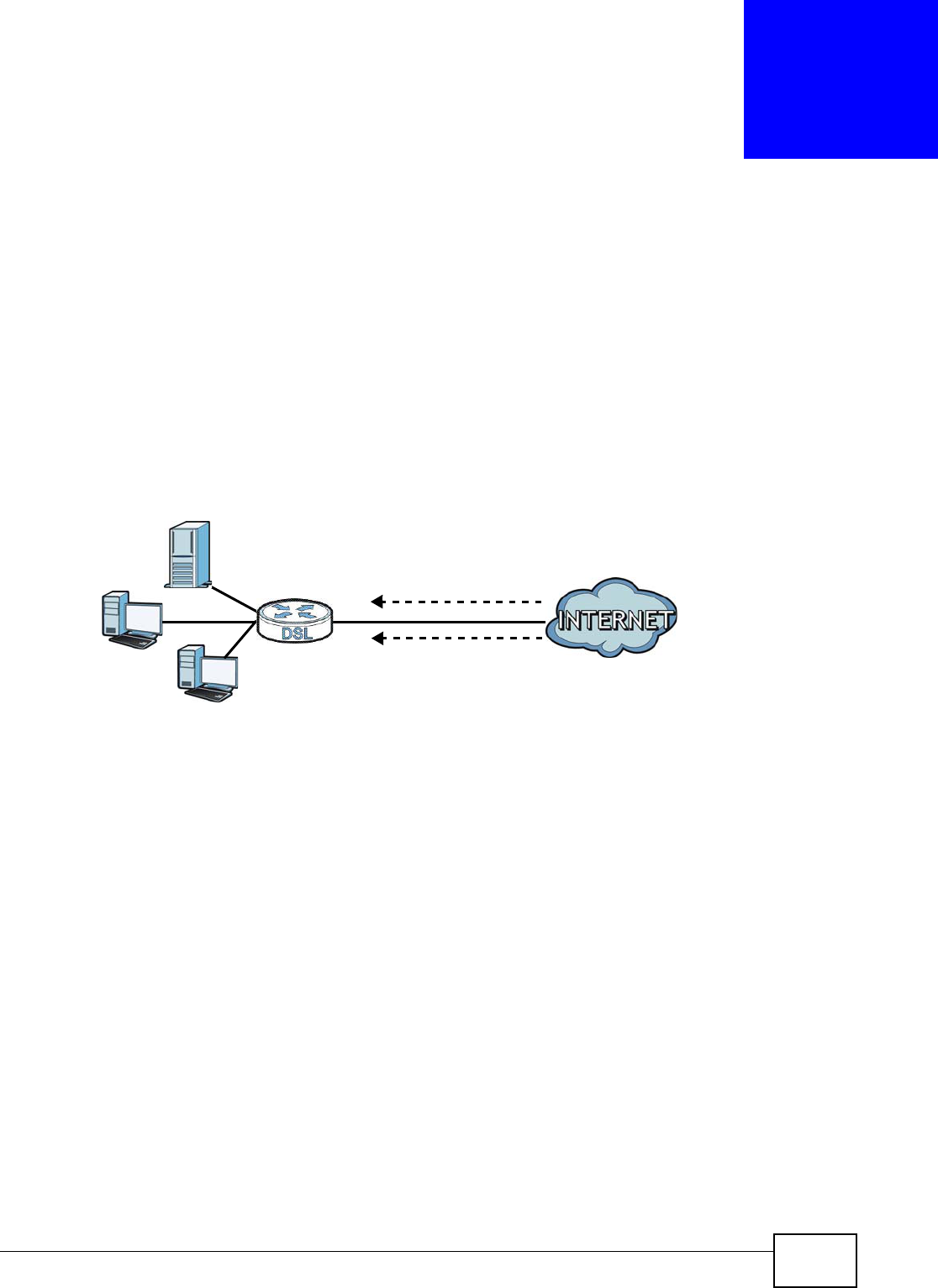
AMG1312-T Series User’s Guide 210
CHAPTER 25
Remote Management
25.1 Overview
Remote management allows you to determine which services/protocols can access which
AMG1312-T Series interface (if any) from which computers.
The following figure shows remote management of the AMG1312-T Series coming in from the WAN.
Figure 120 Remote Management From the WAN
Note: When you configure remote management to allow management from the WAN, you
still need to configure a IP filter rule to allow access.
You may manage your AMG1312-T Series from a remote location via:
• Internet (WAN only)
•LAN only
•LAN and WAN
• None (Disable)
To disable remote management of a service, select Disable in the corresponding Service Access
field.
25.1.1 What You Can Do in the Remote Management Screens
•Use the WWW screen (Section 25.2 on page 211) to configure through which interface(s) and
from which IP address(es) users can use HTTP to manage the AMG1312-T Series.
•Use the Telnet screen (Section 25.3 on page 213) to configure through which interface(s) and
from which IP address(es) users can use Telnet to manage the AMG1312-T Series.
•Use the FTP screen (Section 25.4 on page 213) to configure through which interface(s) and from
which IP address(es) users can use FTP to access the AMG1312-T Series.
LAN WAN
HTTP
Telnet

Chapter 25 Remote Management
AMG1312-T Series User’s Guide 211
• Your AMG1312-T Series can act as an SNMP agent, which allows a manager station to manage
and monitor the AMG1312-T Series through the network. Use the SNMP screen (see Section
25.5 on page 214) to configure through which interface(s) and from which IP address(es) users
can use SNMP to access the AMG1312-T Series.
•Use the DNS screen (Section 25.6 on page 217) to configure through which interface(s) and
from which IP address(es) users can send DNS queries to the AMG1312-T Series.
•Use the ICMP screen (Section 25.7 on page 217) to set whether or not your AMG1312-T Series
will respond to pings and probes for services that you have not made available.
•Use the SSH screen (Section 25.8 on page 218) to configure through which interface(s) and from
which IP address(es) users can use SSH to manage the AMG1312-T Series.
25.1.2 What You Need to Know About Remote Management
Remote Management Limitations
Remote management does not work when:
• You have not enabled that service on the interface in the corresponding remote management
screen.
• You have disabled that service in one of the remote management screens.
• The IP address in the Secured Client IP Address field does not match the client IP address. If
it does not match, the AMG1312-T Series will disconnect the session immediately.
• There is a firewall rule that blocks it.
Remote Management and NAT
When NAT is enabled:
• Use the AMG1312-T Series’s WAN IP address when configuring from the WAN.
• Use the AMG1312-T Series’s LAN IP address when configuring from the LAN.
25.2 The WWW Screen
Use this screen to specify how to connect to the AMG1312-T Series from a web browser, such as
Internet Explorer.
25.2.1 Configuring the WWW Screen
Click Maintenance > RemoteMGMT to display the WWW screen.
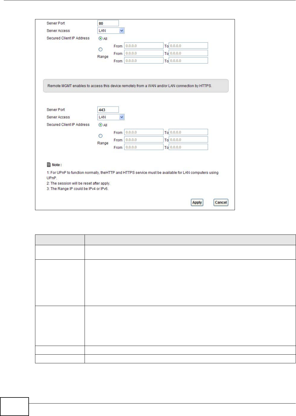
Chapter 25 Remote Management
AMG1312-T Series User’s Guide
212
Figure 121 Maintenance > RemoteMGMT > WWW
The following table describes the labels in this screen.
Table 89 Maintenance > RemoteMGMT > WWW
LABEL DESCRIPTION
Server Port This displays the service port number for accessing the AMG1312-T Series using HTTP or
HTTPS. If the number is grayed out, it is not editable.
Server Access Select the interface(s) through which a computer may access the AMG1312-T Series
using this service.
Note: It is recommended if you are allowing WAN access even temporarily to change the
default password (in Maintenance > User Account). To allow access from the
WAN, you will need to configure a WAN to Router firewall rule. See Section 4.1 on
page 34 for information on configuring firewall rules.
Secured Client IP
Address
A secured client is a “trusted” computer that is allowed to communicate with the
AMG1312-T Series using this service.
Select All to allow any computer to access the AMG1312-T Series using this service.
Choose Range to just allow the computer(s) with an IP address in the range that you
specify to access the AMG1312-T Series using this service.
Apply Click this to save your changes.
Cancel Click this to restore your previously saved settings.
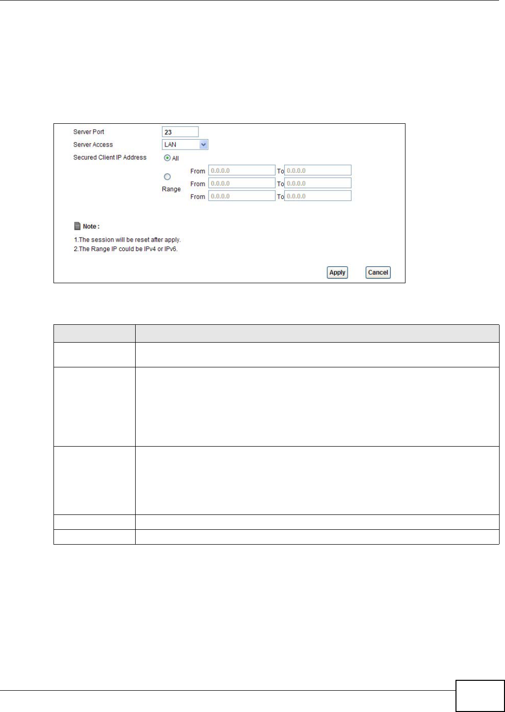
Chapter 25 Remote Management
AMG1312-T Series User’s Guide 213
25.3 The Telnet Screen
You can use Telnet to access the AMG1312-T Series’s command line interface. Specify which
interfaces allow Telnet access and from which IP address the access can come.
Click Maintenance > RemoteMGMT > Telnet tab to display the screen as shown.
Figure 122 Maintenance > RemoteMGMT > Telnet
The following table describes the labels in this screen.
25.4 The FTP Screen
You can use FTP (File Transfer Protocol) to upload and download the AMG1312-T Series’s firmware
and configuration files. Please see the User’s Guide chapter on firmware and configuration file
maintenance for details. To use this feature, your computer must have an FTP client.
Table 90 Maintenance > RemoteMGMT > Telnet
LABEL DESCRIPTION
Server Port This displays the service port number for accessing the AMG1312-T Series. If the number
is grayed out, it is not editable.
Server Access Select the interface(s) through which a computer may access the AMG1312-T Series
using this service.
Note: It is recommended if you are allowing WAN access even temporarily to change the
default password (in Maintenance > User Account). To allow access from the
WAN, you will need to configure a WAN to Router firewall rule. See Firewall Section
on page 168 for information on configuring firewall rules.
Secured Client IP
Address
A secured client is a “trusted” computer that is allowed to communicate with the
AMG1312-T Series using this service.
Select All to allow any computer to access the AMG1312-T Series using this service.
Choose Range to just allow the computer(s) with an IP address in the range that you
specify to access the AMG1312-T Series using this service.
Apply Click this to save your changes.
Cancel Click this to restore your previously saved settings.
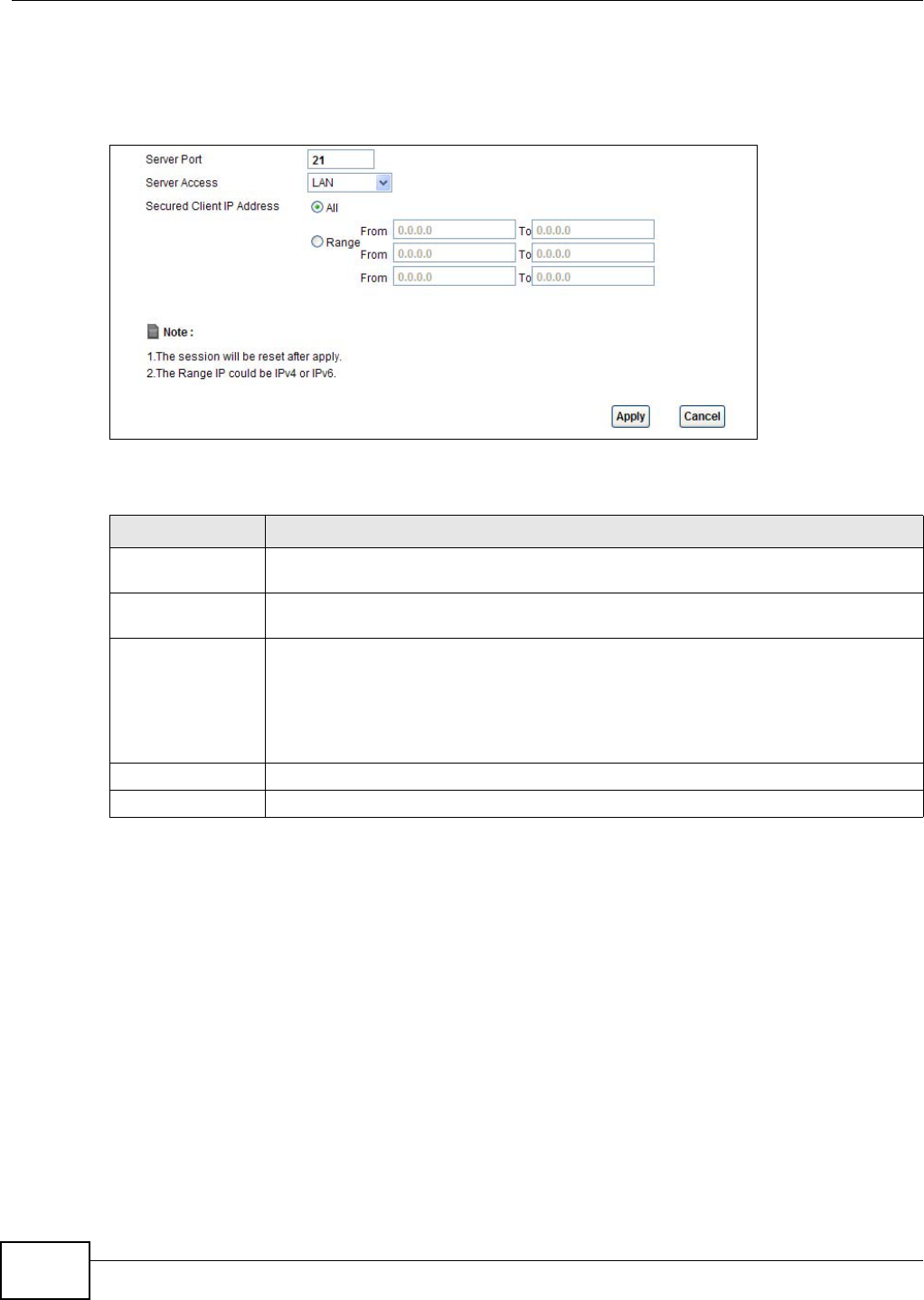
Chapter 25 Remote Management
AMG1312-T Series User’s Guide
214
Use this screen to specify which interfaces allow FTP access and from which IP address the access
can come. To change your AMG1312-T Series’s FTP settings, click Maintenance > RemoteMGMT
> FTP. The screen appears as shown.
Figure 123 Maintenance > RemoteMGMT > FTP
The following table describes the labels in this screen.
25.5 The SNMP Screen
Simple Network Management Protocol is a protocol used for exchanging management information
between network devices. Your AMG1312-T Series supports SNMP agent functionality, which allows
a manager station to manage and monitor the AMG1312-T Series through the network. The
AMG1312-T Series supports SNMP version one (SNMPv1) and version two (SNMPv2c). The next
figure illustrates an SNMP management operation.
Table 91 Maintenance > RemoteMGMT > FTP
LABEL DESCRIPTION
Server Port This displays the service port number for accessing the AMG1312-T Series. If the
number is grayed out, it is not editable.
Server Access Select the interface(s) through which a computer may access the AMG1312-T Series
using this service.
Secured Client IP
Address
A secured client is a “trusted” computer that is allowed to communicate with the
AMG1312-T Series using this service.
Select All to allow any computer to access the AMG1312-T Series using this service.
Choose Range to just allow the computer(s) with an IP address in the range that you
specify to access the AMG1312-T Series using this service.
Apply Click this to save your changes.
Cancel Click this to restore your previously saved settings.
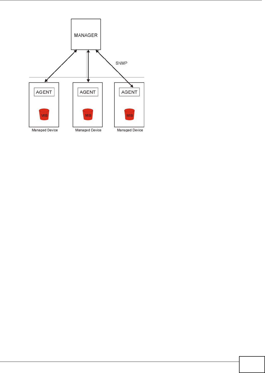
Chapter 25 Remote Management
AMG1312-T Series User’s Guide 215
Figure 124 SNMP Management Model
An SNMP managed network consists of two main types of component: agents and a manager.
An agent is a management software module that resides in a managed device (the AMG1312-T
Series). An agent translates the local management information from the managed device into a
form compatible with SNMP. The manager is the console through which network administrators
perform network management functions. It executes applications that control and monitor
managed devices.
The managed devices contain object variables/managed objects that define each piece of
information to be collected about a device. Examples of variables include such as number of
packets received, node port status etc. A Management Information Base (MIB) is a collection of
managed objects. SNMP allows a manager and agents to communicate for the purpose of accessing
these objects.
25.5.1 Configuring SNMP
To change your AMG1312-T Series’s SNMP settings, click Maintenance > RemoteMGMT > SNMP
tab. The screen appears as shown.
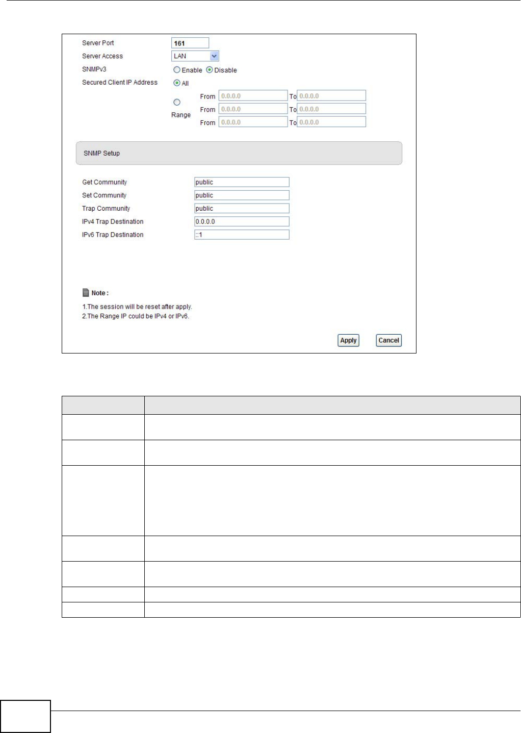
Chapter 25 Remote Management
AMG1312-T Series User’s Guide
216
Figure 125 Maintenance > RemoteMGMT > SNMP
The following table describes the labels in this screen.
Table 92 Maintenance > RemoteMGMT > SNMP
LABEL DESCRIPTION
Server Port This displays the port the SNMP agent listens on. If the number is grayed out, it is not
editable.
Server Access Select the interface(s) through which a computer may access the AMG1312-T Series
using this service.
Secured Client IP
Address
A secured client is a “trusted” computer that is allowed to access the SNMP agent on the
AMG1312-T Series.
Select All to allow any computer to access the SNMP agent.
Choose Range to just allow the computer(s) with an IP address in the range that you
specify to access the AMG1312-T Series using this service.
Get Community Enter the Get Community, which is the password for the incoming Get and GetNext
requests from the management station. The default is public and allows all requests.
Set Community Enter the Set community, which is the password for incoming Set requests from the
management station. The default is public and allows all requests.
Apply Click Apply to save your changes back to the AMG1312-T Series.
Cancel Click Cancel to begin configuring this screen afresh.
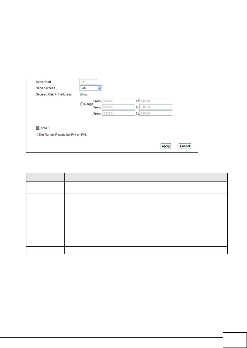
Chapter 25 Remote Management
AMG1312-T Series User’s Guide 217
25.6 The DNS Screen
Use DNS (Domain Name System) to map a domain name to its corresponding IP address and vice
versa.
Use this screen to set from which IP address the AMG1312-T Series will accept DNS queries and on
which interface it can send them your AMG1312-T Series’s DNS settings. This feature is not
available when the AMG1312-T Series is set to bridge mode. Click Maintenance > RemoteMGMT
> DNS to change your AMG1312-T Series’s DNS settings.
Figure 126 Maintenance > RemoteMGMT > DNS
The following table describes the labels in this screen.
25.7 The ICMP Screen
To change your AMG1312-T Series’s security settings, click Maintenance > RemoteMGMT >
ICMP. The screen appears as shown.
If an outside user attempts to probe an unsupported port on your AMG1312-T Series, an ICMP
response packet is automatically returned. This allows the outside user to know the AMG1312-T
Series exists. Your AMG1312-T Series supports anti-probing, which prevents the ICMP response
Table 93 Maintenance > RemoteMGMT > DNS
LABEL DESCRIPTION
Server Port This displays the service port number for accessing the AMG1312-T Series. If the
number is grayed out, it is not editable.
Access Status Select the interface(s) through which a computer may send DNS queries to the
AMG1312-T Series.
Secured Client IP
Address
A secured client is a “trusted” computer that is allowed to send DNS queries to
the AMG1312-T Series.
Select All to allow any computer to send DNS queries to the AMG1312-T Series.
Choose Range to just allow the computer(s) with an IP address in the range that
you specify to send DNS queries to the AMG1312-T Series.
Apply Click this to save your changes.
Cancel Click this to restore your previously saved settings.
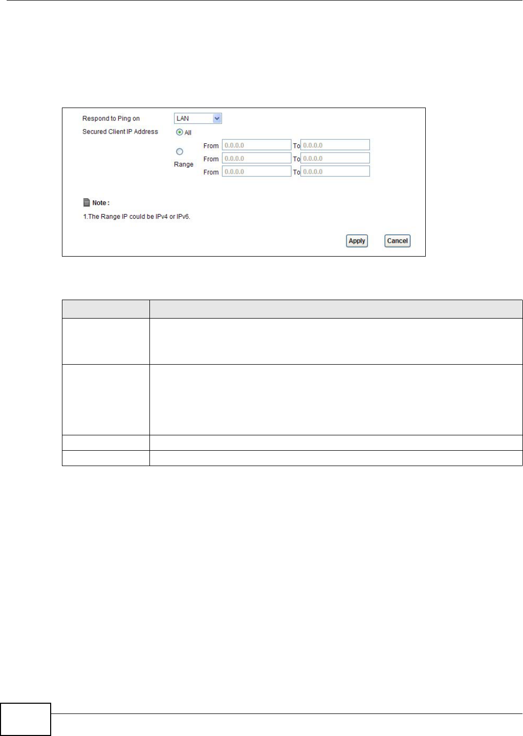
Chapter 25 Remote Management
AMG1312-T Series User’s Guide
218
packet from being sent. This keeps outsiders from discovering your AMG1312-T Series when
unsupported ports are probed.
Note: If you want your device to respond to pings and requests for unauthorized services,
you will also need to configure the firewall accordingly by disabling SPI.
Figure 127 Maintenance > RemoteMGMT > ICMP
The following table describes the labels in this screen.
25.8 The SSH Screen
You can use Secure SHell (SSH) to securely access the AMG1312-T Series’s command line interface.
Specify which interfaces allow SSH access and from which IP address the access can come. SSH is
a secure communication protocol that combines authentication and data encryption to provide
secure encrypted communication between two hosts over an unsecured network.
Click Maintenance > RemoteMGMT > SSH tab to display the screen as shown.
Table 94 Maintenance > RemoteMGMT > ICMP
LABEL DESCRIPTION
Respond to Ping on The AMG1312-T Series will not respond to any incoming Ping requests when Disable is
selected. Select LAN to reply to incoming LAN Ping requests. Select WAN to reply to
incoming WAN Ping requests. Otherwise select LAN & WAN to reply to both incoming
LAN and WAN Ping requests.
Secured Client IP
Address
A secured client is a “trusted” computer that is allowed to send Ping requests to the
AMG1312-T Series.
Select All to allow any computer to send Ping requests to the AMG1312-T Series.
Choose Range to just allow the computer(s) with an IP address in the range that you
specify to send Ping requests to the AMG1312-T Series.
Apply Click this to save your changes.
Cancel Click this to restore your previously saved settings.
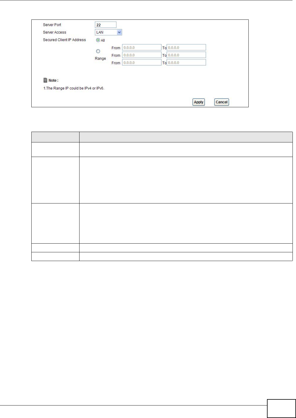
Chapter 25 Remote Management
AMG1312-T Series User’s Guide 219
Figure 128 Maintenance > RemoteMGMT > SSH
The following table describes the labels in this screen.
25.8.1 SSH Example
This section shows an example using a graphical interface SSH client program to remotely access
the ZyXEL Device. The configuration and connection steps are similar for most SSH client programs.
Refer to your SSH client program user’s guide.
1Enter the IP address and port number. Select SSH.
Table 95 Maintenance > RemoteMGMT > SSH
LABEL DESCRIPTION
Server Port This displays the service port number for accessing the AMG1312-T Series. If the number
is grayed out, it is not editable.
Server Access Select the interface(s) through which a computer may access the AMG1312-T Series
using this service.
Note: It is recommended if you are allowing WAN access even temporarily to change the
default password (in Maintenance > User Account). To allow access from the
WAN, you will need to configure a WAN to Router firewall rule. See Firewall Section
on page 168 for information on configuring firewall rules.
Secured Client IP
Address
A secured client is a “trusted” computer that is allowed to communicate with the
AMG1312-T Series using this service.
Select All to allow any computer to access the AMG1312-T Series using this service.
Choose Range to just allow the computer(s) with an IP address in the range that you
specify to access the AMG1312-T Series using this service.
Apply Click this to save your changes.
Cancel Click this to restore your previously saved settings.
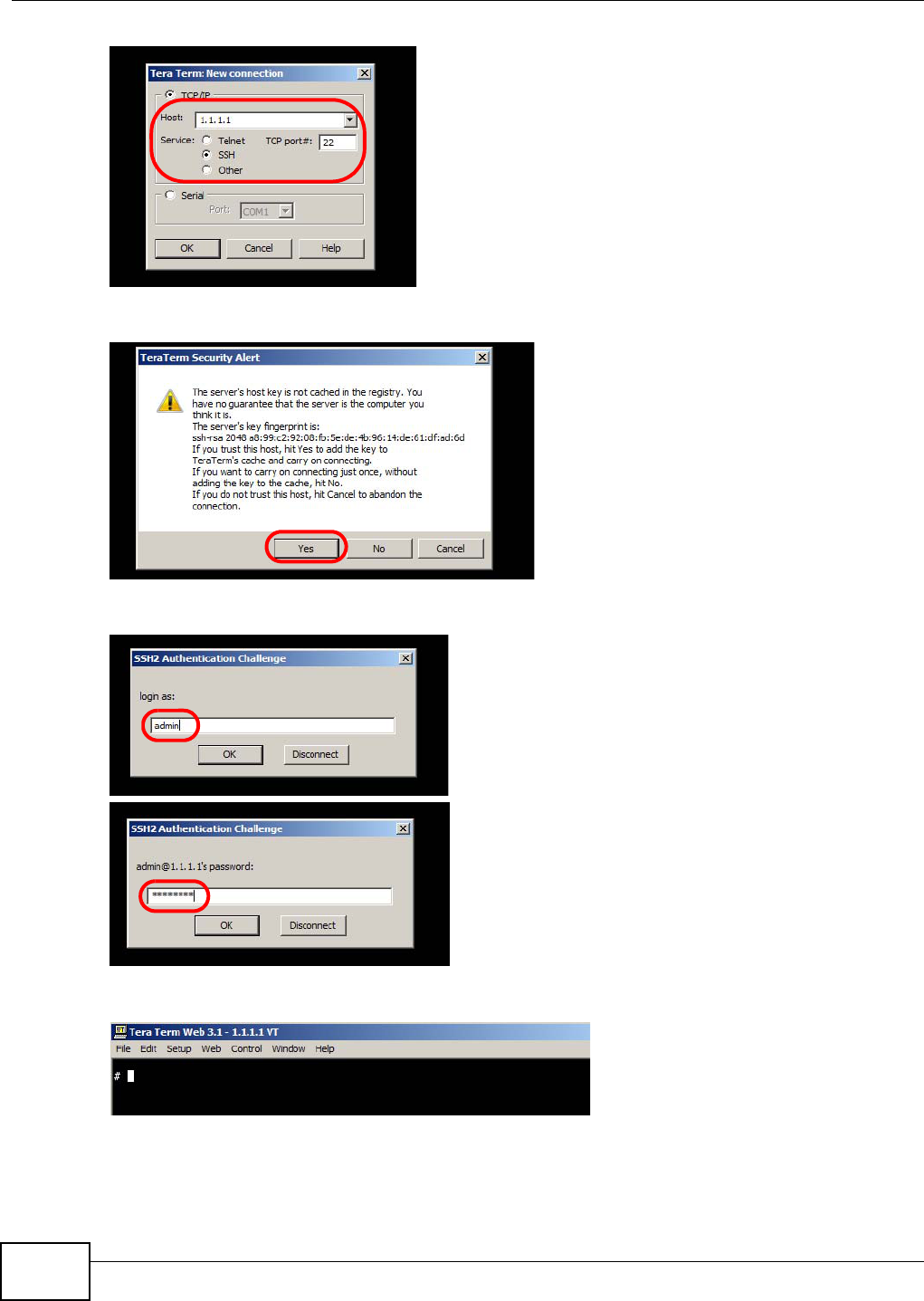
Chapter 25 Remote Management
AMG1312-T Series User’s Guide
220
2 A window displays prompting you to store the host key in your computer. Click Yes to continue.
3Enter your user name and password.
4The command line interface displays.
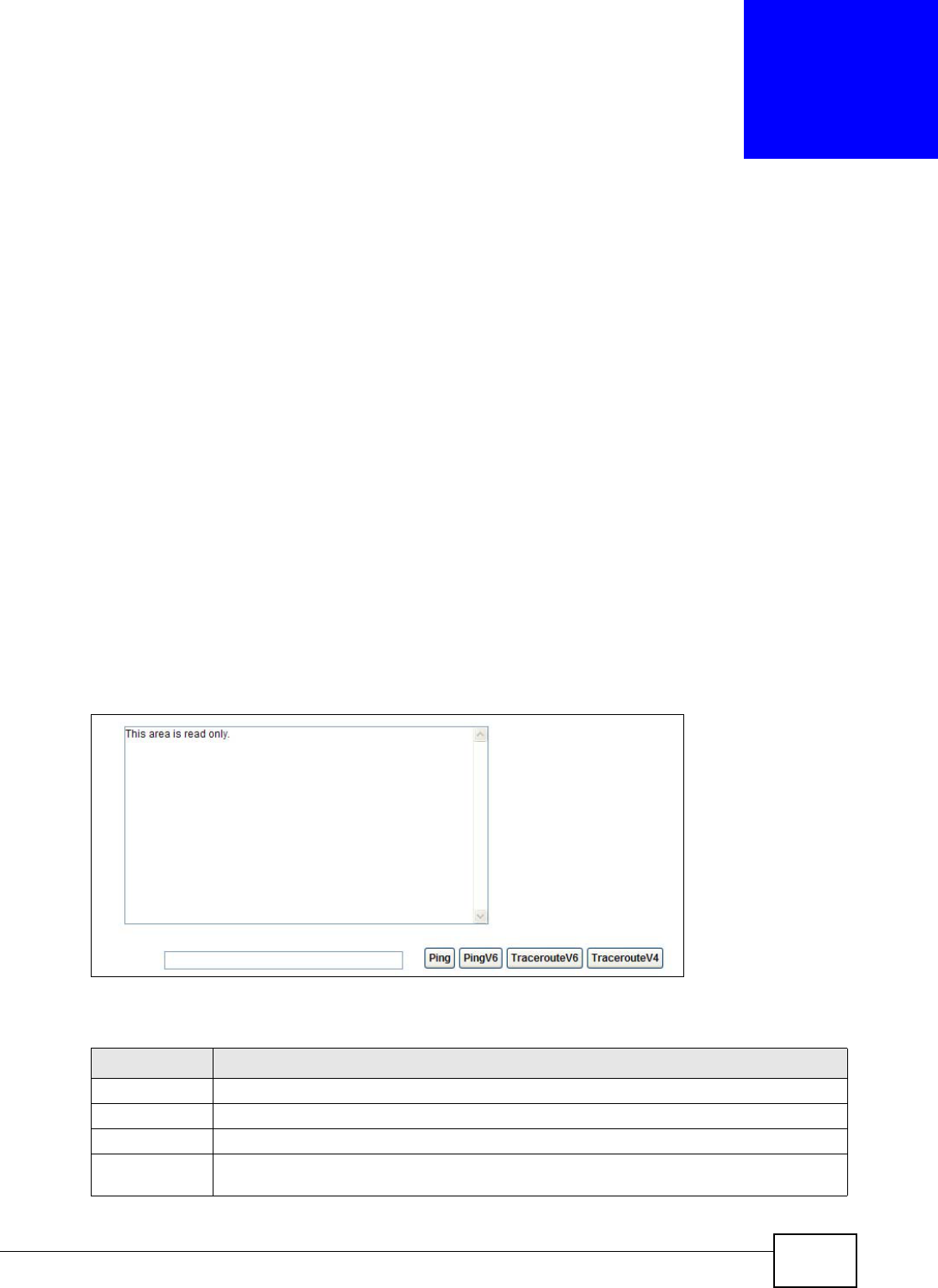
AMG1312-T Series User’s Guide 221
CHAPTER 26
Diagnostic
26.1 Overview
These read-only screens display information to help you identify problems with the AMG1312-T
Series.
26.1.1 What You Can Do in the Diagnostic Screens
•Use the Ping screen (Section 26.2 on page 221) to ping an IP address.
•Use the DSL Line screen (Section 26.3 on page 222) to view the DSL line statistics and reset the
ADSL line.
26.2 The General Screen
Use this screen to ping an IP address. Click Maintenance > Diagnostic > Ping to open the screen
shown next.
Figure 129 Maintenance > Diagnostic > Ping
The following table describes the fields in this screen.
Table 96 Maintenance > Diagnostic > Ping
LABEL DESCRIPTION
Type the IP address of a computer that you want to ping in order to test a connection.
Ping Click this to ping the IP address that you entered.
PingV6 Click this to ping the IPv6 address that you entered.
TracerouteV6 Click this to display the route path and transmission delays between the AMG1312-T Series
to the IPv6 address that you entered.
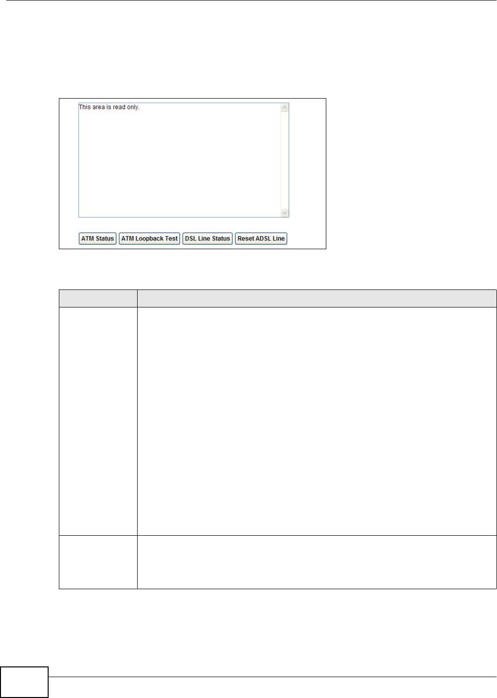
Chapter 26 Diagnostic
AMG1312-T Series User’s Guide
222
26.3 The DSL Line Screen
Use this screen to view the DSL line statistics and reset the ADSL line. Click Maintenance >
Diagnostic > DSL Line to open the screen shown next.
Figure 130 Maintenance > Diagnostic > DSL Line
The following table describes the fields in this screen.
Table 97 Maintenance > Diagnostic > DSL Line
LABEL DESCRIPTION
ATM Status Click this to view your DSL connection’s Asynchronous Transfer Mode (ATM) statistics.
ATM is a networking technology that provides high-speed data transfer. ATM uses fixed-
size packets of information called cells. With ATM, a high QoS (Quality of Service) can be
guaranteed.
The (Segmentation and Reassembly) SAR driver translates packets into ATM cells. It also
receives ATM cells and reassembles them into packets.
These counters are set back to zero whenever the device starts up.
inPkts is the number of good ATM cells that have been received.
inDiscards is the number of received ATM cells that were rejected.
inF4Pkts is the number of ATM Operations, Administration, and Management (OAM) F4
cells that have been received. See ITU recommendation I.610 for more on OAM for ATM.
inF5Pkts is the number of ATM OAM F5 cells that have been received.
outPkts is the number of ATM cells that have been sent.
outDiscards is the number of ATM cells sent that were rejected.
outF4Pkts is the number of ATM OAM F4 cells that have been sent.
outF5Pkts is the number of ATM OAM F5 cells that have been sent.
ATM Loopback
Test
Click this to start the ATM loopback test. Make sure you have configured at least one PVC
with proper VPIs/VCIs before you begin this test. The AMG1312-T Series sends an OAM F5
packet to the DSLAM/ATM switch and then returns it (loops it back) to the AMG1312-T
Series. The ATM loopback test is useful for troubleshooting problems with the DSLAM and
ATM network.

Chapter 26 Diagnostic
AMG1312-T Series User’s Guide 223
DSL Line Status Click this to view statistics about the DSL connections.
noise margin downstream is the signal to noise ratio for the downstream part of the
connection (coming into the AMG1312-T Series from the ISP). It is measured in decibels.
The higher the number the more signal and less noise there is.
output power upstream is the amount of power (in decibels) that the AMG1312-T
Series is using to transmit to the ISP.
attenuation downstream is the reduction in amplitude (in decibels) of the DSL signal
coming into the AMG1312-T Series from the ISP.
Discrete Multi-Tone (DMT) modulation divides up a line’s bandwidth into sub-carriers
(sub-channels) of 4.3125 KHz each called tones. The rest of the display is the line’s bit
allocation. This is displayed as the number (in hexadecimal format) of bits transmitted for
each tone. This can be used to determine the quality of the connection, whether a given
sub-carrier loop has sufficient margins to support certain ADSL transmission rates, and
possibly to determine whether particular specific types of interference or line attenuation
exist. Refer to the ITU-T G.992.1 recommendation for more information on DMT.
The better (or shorter) the line, the higher the number of bits transmitted for a DMT tone.
The maximum number of bits that can be transmitted per DMT tone is 15. There will be
some tones without any bits as there has to be space between the upstream and
downstream channels.
Reset ADSL Line Click this to reinitialize the ADSL line. The large text box above then displays the progress
and results of this operation, for example:
"Start to reset ADSL
Loading ADSL modem F/W...
Reset ADSL Line Successfully!"
Table 97 Maintenance > Diagnostic > DSL Line (continued)
LABEL DESCRIPTION

AMG1312-T Series User’s Guide 224
CHAPTER 27
Troubleshooting
This chapter offers some suggestions to solve problems you might encounter. The potential
problems are divided into the following categories.
•Power, Hardware Connections, and LEDs
•AMG1312-T Series Access and Login
•Internet Access
27.1 Power, Hardware Connections, and LEDs
The AMG1312-T Series does not turn on. None of the LEDs turn on.
1Make sure the AMG1312-T Series is turned on.
2Make sure you are using the power adaptor or cord included with the AMG1312-T Series.
3Make sure the power adaptor or cord is connected to the AMG1312-T Series and plugged in to an
appropriate power source. Make sure the power source is turned on.
4Turn the AMG1312-T Series off and on.
5If the problem continues, contact the vendor.
One of the LEDs does not behave as expected.
1Make sure you understand the normal behavior of the LED. Section 1.5 on page 16
2Check the hardware connections.
3Inspect your cables for damage. Contact the vendor to replace any damaged cables.
LABEL DESCRIPTION
WPS LED Green: successful connection
Off: connection failure
WIFI LED Green: WIFI active
Off: WIFI inactive
Chapter 27 Troubleshooting
AMG1312-T Series User’s Guide 225
4Turn the AMG1312-T Series off and on.
5If the problem continues, contact the vendor.
27.2 AMG1312-T Series Access and Login
I forgot the IP address for the AMG1312-T Series.
1The default IP address is 192.168.1.1.
2If you changed the IP address and have forgotten it, you might get the IP address of the AMG1312-
T Series by looking up the IP address of the default gateway for your computer. To do this in most
Windows computers, click Start > Run, enter cmd, and then enter ipconfig. The IP address of the
Default Gateway might be the IP address of the AMG1312-T Series (it depends on the network),
so enter this IP address in your Internet browser.
3If this does not work, you have to reset the device to its factory defaults. See Section 1.7 on page
18.
I forgot the password.
1The default admin user name and password can be found on the cover of this User’s Guide.
2If this does not work, you have to reset the device to its factory defaults. See Section 1.7 on page
18.
I cannot see or access the Login screen for the web configurator.
1Make sure you are using the correct IP address.
• The default IP address is 192.168.1.1.
• If you changed the IP address (Section 8.2 on page 117), use the new IP address.
• If you changed the IP address and have forgotten it, see the troubleshooting suggestions for I
forgot the IP address for the AMG1312-T Series.
2Check the hardware connections, and make sure the LEDs are behaving as expected. See the Quick
Start Guide.
3Make sure your Internet browser does not block pop-up windows and has JavaScripts and Java
enabled. See Appendix C on page 257.

Chapter 27 Troubleshooting
AMG1312-T Series User’s Guide
226
4Reset the device to its factory defaults, and try to access the AMG1312-T Series with the default IP
address. See Section 1.7 on page 18.
5If the problem continues, contact the network administrator or vendor, or try one of the advanced
suggestions.
Advanced Suggestions
• Try to access the AMG1312-T Series using another service, such as Telnet. If you can access the
AMG1312-T Series, check the remote management settings and firewall rules to find out why the
AMG1312-T Series does not respond to HTTP.
• If your computer is connected to the DSL port or is connected wirelessly, use a computer that is
connected to a ETHERNET port.
I can see the Login screen, but I cannot log in to the AMG1312-T Series.
1Make sure you have entered the password correctly. The default user and default admin password
can be found on the cover page of this User’s Guide. The field is case-sensitive, so make sure [Caps
Lock] is not on.
2You cannot log in to the web configurator while someone is using Telnet to access the AMG1312-T
Series. Log out of the AMG1312-T Series in the other session, or ask the person who is logged in to
log out.
3Turn the AMG1312-T Series off and on.
4If this does not work, you have to reset the device to its factory defaults. See Section 1.7 on page
18.
I cannot Telnet to the AMG1312-T Series.
See the troubleshooting suggestions for I cannot see or access the Login screen for the web
configurator. Ignore the suggestions about your browser.
I cannot use FTP to upload / download the configuration file. / I cannot use FTP to upload
new firmware.
See the troubleshooting suggestions for I cannot see or access the Login screen for the web
configurator. Ignore the suggestions about your browser.
Chapter 27 Troubleshooting
AMG1312-T Series User’s Guide 227
27.3 Internet Access
I cannot access the Internet.
1Check the hardware connections, and make sure the LEDs are behaving as expected. See the Quick
Start Guide and Section 27.1 on page 225.
2Make sure you entered your ISP account information correctly in the wizard. These fields are case-
sensitive, so make sure [Caps Lock] is not on.
3If you are trying to access the Internet wirelessly, make sure the wireless settings in the wireless
client are the same as the settings in the AP.
4If you are trying to access the Internet wirelessly, make sure you enabled the wireless LAN and
have selected the correct country and channel in which your AMG1312-T Series operates in the
Wireless LAN > AP screen.
5Disconnect all the cables from your device, and follow the directions in the Quick Start Guide again.
6If the problem continues, contact your ISP.
I cannot access the Internet anymore. I had access to the Internet (with the AMG1312-T
Series), but my Internet connection is not available anymore.
1Check the hardware connections, and make sure the LEDs are behaving as expected. See the Quick
Start Guide and Section 27.1 on page 225.
2Turn the AMG1312-T Series off and on.
3If the problem continues, contact your ISP.
The Internet connection is slow or intermittent.
1There might be a lot of traffic on the network. Look at the LEDs, and check Section 27.1 on page
225. If the AMG1312-T Series is sending or receiving a lot of information, try closing some
programs that use the Internet, especially peer-to-peer applications.
2Check the signal strength. If the signal strength is low, try moving your computer closer to the
AMG1312-T Series if possible, and look around to see if there are any devices that might be
interfering with the wireless network (for example, microwaves, other wireless networks, and so
on).
3Turn the AMG1312-T Series off and on.

Chapter 27 Troubleshooting
AMG1312-T Series User’s Guide
228
4If the problem continues, contact the network administrator or vendor, or try one of the advanced
suggestions.
Advanced Suggestions
• Check the settings for QoS. If it is disabled, you might consider activating it. If it is enabled, you
might consider raising or lowering the priority for some applications.
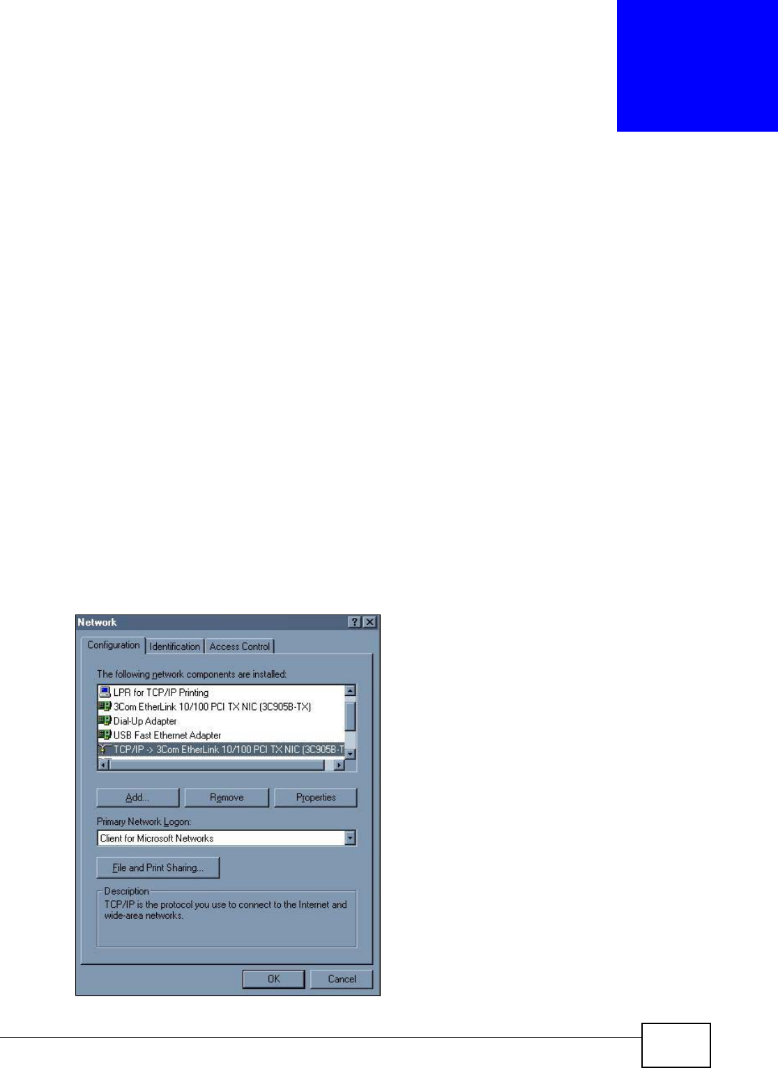
AMG1312-T Series User’s Guide 229
APPENDIX A
Setting up Your Computer’s IP Address
All computers must have a 10M or 100M Ethernet adapter and TCP/IP installed.
Windows 95/98/Me/NT/2000/XP/Vista, Macintosh OS 7 and later operating systems and all versions
of UNIX/LINUX include the software components you need to install and use TCP/IP on your
computer. Windows 3.1 requires the purchase of a third-party TCP/IP application package.
TCP/IP should already be installed on computers using Windows NT/2000/XP, Macintosh OS 7 and
later operating systems.
After the appropriate TCP/IP components are installed, configure the TCP/IP settings in order to
"communicate" with your network.
If you manually assign IP information instead of using dynamic assignment, make sure that your
computers have IP addresses that place them in the same subnet as the AMG1312-T Series’s LAN
port.
Windows 95/98/Me
Click Start, Settings, Control Panel and double-click the Network icon to open the Network
window.
Figure 131 WIndows 95/98/Me: Network: Configuration

Appendix A Setting up Your Computer’s IP Address
AMG1312-T Series User’s Guide
230
Installing Components
The Network window Configuration tab displays a list of installed components. You need a
network adapter, the TCP/IP protocol and Client for Microsoft Networks.
If you need the adapter:
1In the Network window, click Add.
2Select Adapter and then click Add.
3Select the manufacturer and model of your network adapter and then click OK.
If you need TCP/IP:
1In the Network window, click Add.
2Select Protocol and then click Add.
3Select Microsoft from the list of manufacturers.
4Select TCP/IP from the list of network protocols and then click OK.
If you need Client for Microsoft Networks:
1Click Add.
2Select Client and then click Add.
3Select Microsoft from the list of manufacturers.
4Select Client for Microsoft Networks from the list of network clients and then click OK.
5Restart your computer so the changes you made take effect.
Configuring
1In the Network window Configuration tab, select your network adapter's TCP/IP entry and click
Properties
2Click the IP Address tab.
• If your IP address is dynamic, select Obtain an IP address automatically.
• If you have a static IP address, select Specify an IP address and type your information into
the IP Address and Subnet Mask fields.
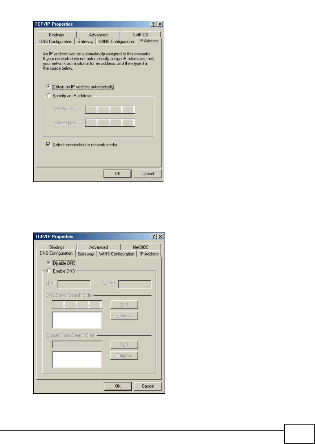
Appendix A Setting up Your Computer’s IP Address
AMG1312-T Series User’s Guide 231
Figure 132 Windows 95/98/Me: TCP/IP Properties: IP Address
3Click the DNS Configuration tab.
• If you do not know your DNS information, select Disable DNS.
• If you know your DNS information, select Enable DNS and type the information in the fields
below (you may not need to fill them all in).
Figure 133 Windows 95/98/Me: TCP/IP Properties: DNS Configuration
4Click the Gateway tab.
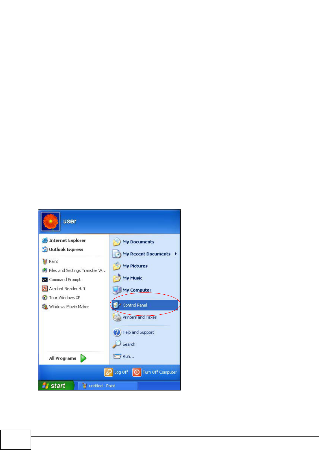
Appendix A Setting up Your Computer’s IP Address
AMG1312-T Series User’s Guide
232
• If you do not know your gateway’s IP address, remove previously installed gateways.
• If you have a gateway IP address, type it in the New gateway field and click Add.
5Click OK to save and close the TCP/IP Properties window.
6Click OK to close the Network window. Insert the Windows CD if prompted.
7Turn on your AMG1312-T Series and restart your computer when prompted.
Verifying Settings
1Click Start and then Run.
2In the Run window, type "winipcfg" and then click OK to open the IP Configuration window.
3Select your network adapter. You should see your computer's IP address, subnet mask and default
gateway.
Windows 2000/NT/XP
The following example figures use the default Windows XP GUI theme.
1Click start (Start in Windows 2000/NT), Settings, Control Panel.
Figure 134 Windows XP: Start Menu
2In the Control Panel, double-click Network Connections (Network and Dial-up Connections
in Windows 2000/NT).
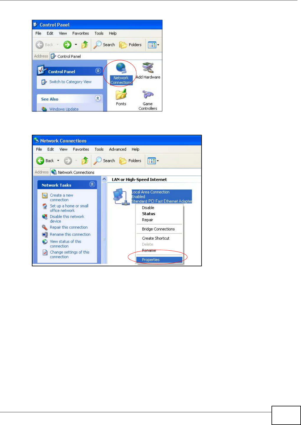
Appendix A Setting up Your Computer’s IP Address
AMG1312-T Series User’s Guide 233
Figure 135 Windows XP: Control Panel
3Right-click Local Area Connection and then click Properties.
Figure 136 Windows XP: Control Panel: Network Connections: Properties
4Select Internet Protocol (TCP/IP) (under the General tab in Win XP) and then click Properties.
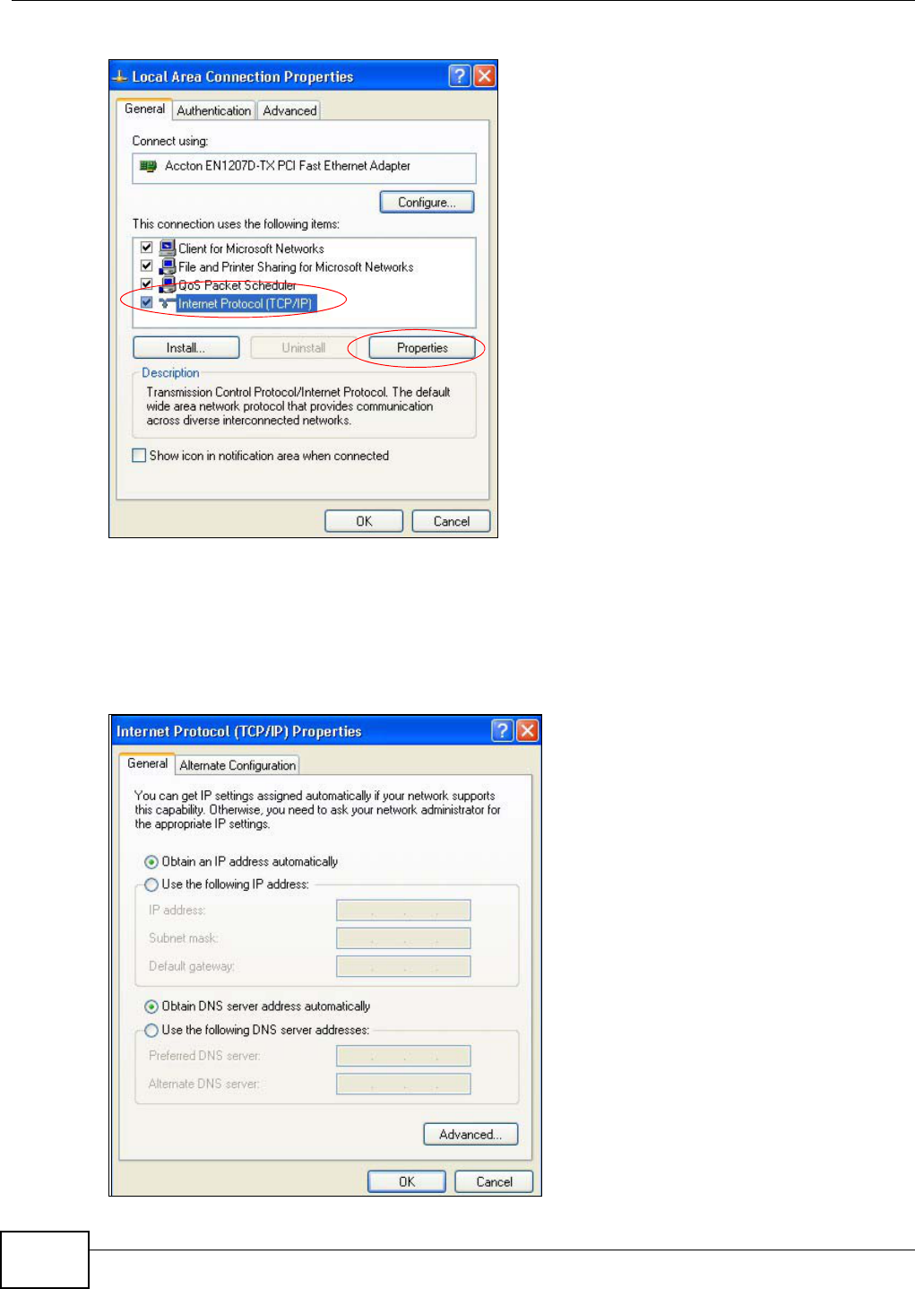
Appendix A Setting up Your Computer’s IP Address
AMG1312-T Series User’s Guide
234
Figure 137 Windows XP: Local Area Connection Properties
5The Internet Protocol TCP/IP Properties window opens (the General tab in Windows XP).
• If you have a dynamic IP address click Obtain an IP address automatically.
• If you have a static IP address click Use the following IP Address and fill in the IP address,
Subnet mask, and Default gateway fields.
• Click Advanced.
Figure 138 Windows XP: Internet Protocol (TCP/IP) Properties
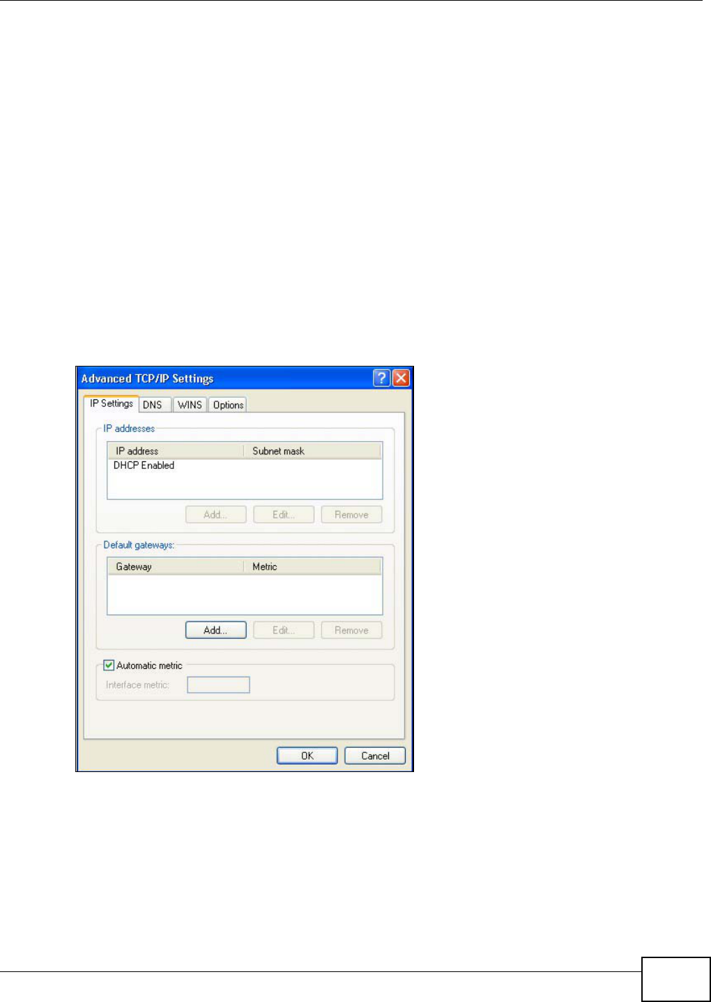
Appendix A Setting up Your Computer’s IP Address
AMG1312-T Series User’s Guide 235
6 If you do not know your gateway's IP address, remove any previously installed gateways in the IP
Settings tab and click OK.
Do one or more of the following if you want to configure additional IP addresses:
•In the IP Settings tab, in IP addresses, click Add.
•In TCP/IP Address, type an IP address in IP address and a subnet mask in Subnet mask,
and then click Add.
• Repeat the above two steps for each IP address you want to add.
• Configure additional default gateways in the IP Settings tab by clicking Add in Default
gateways.
•In TCP/IP Gateway Address, type the IP address of the default gateway in Gateway. To
manually configure a default metric (the number of transmission hops), clear the Automatic
metric check box and type a metric in Metric.
• Click Add.
• Repeat the previous three steps for each default gateway you want to add.
• Click OK when finished.
Figure 139 Windows XP: Advanced TCP/IP Properties
7In the Internet Protocol TCP/IP Properties window (the General tab in Windows XP):
• Click Obtain DNS server address automatically if you do not know your DNS server IP
address(es).
• If you know your DNS server IP address(es), click Use the following DNS server
addresses, and type them in the Preferred DNS server and Alternate DNS server fields.
If you have previously configured DNS servers, click Advanced and then the DNS tab to order
them.
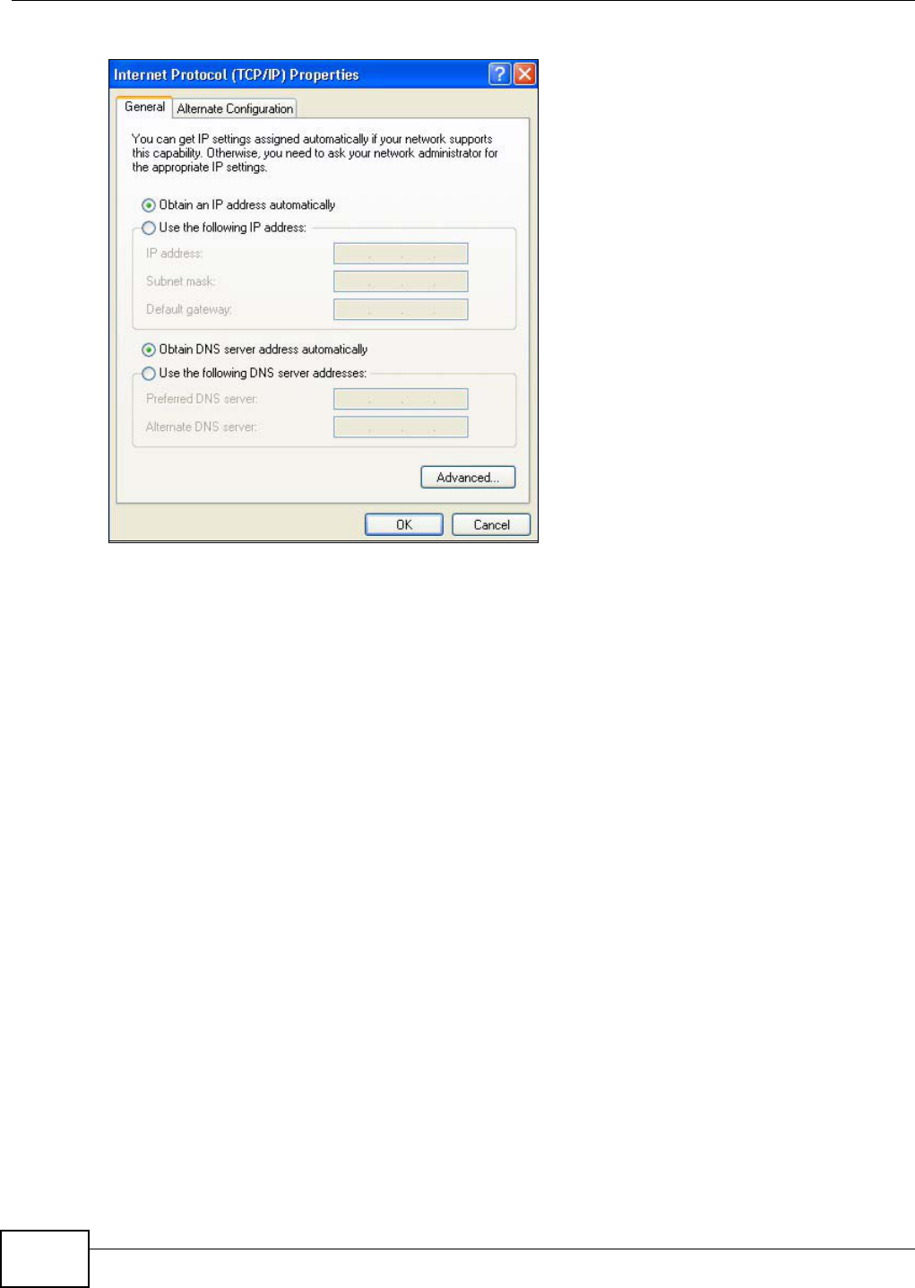
Appendix A Setting up Your Computer’s IP Address
AMG1312-T Series User’s Guide
236
Figure 140 Windows XP: Internet Protocol (TCP/IP) Properties
8Click OK to close the Internet Protocol (TCP/IP) Properties window.
9Click Close (OK in Windows 2000/NT) to close the Local Area Connection Properties window.
10 Close the Network Connections window (Network and Dial-up Connections in Windows
2000/NT).
11 Turn on your AMG1312-T Series and restart your computer (if prompted).
Verifying Settings
1Click Start, All Programs, Accessories and then Command Prompt.
2In the Command Prompt window, type "ipconfig" and then press [ENTER]. You can also open
Network Connections, right-click a network connection, click Status and then click the Support
tab.
Windows Vista
This section shows screens from Windows Vista Enterprise Version 6.0.
1Click the Start icon, Control Panel.
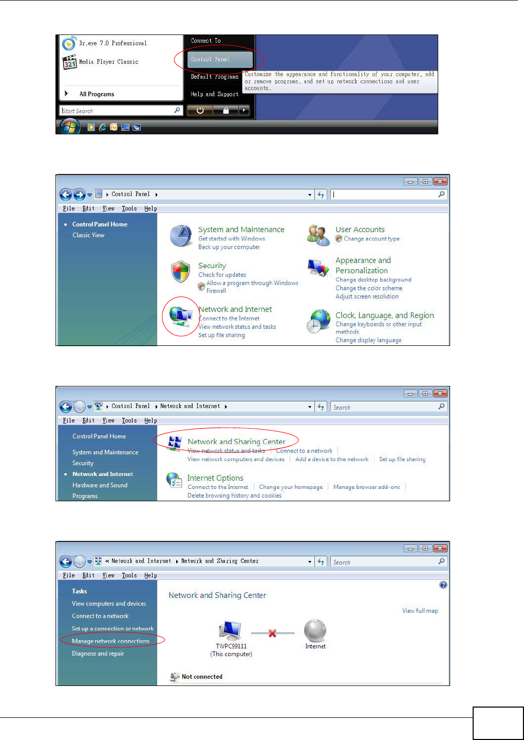
Appendix A Setting up Your Computer’s IP Address
AMG1312-T Series User’s Guide 237
Figure 141 Windows Vista: Start Menu
2In the Control Panel, double-click Network and Internet.
Figure 142 Windows Vista: Control Panel
3Click Network and Sharing Center.
Figure 143 Windows Vista: Network And Internet
4Click Manage network connections.
Figure 144 Windows Vista: Network and Sharing Center
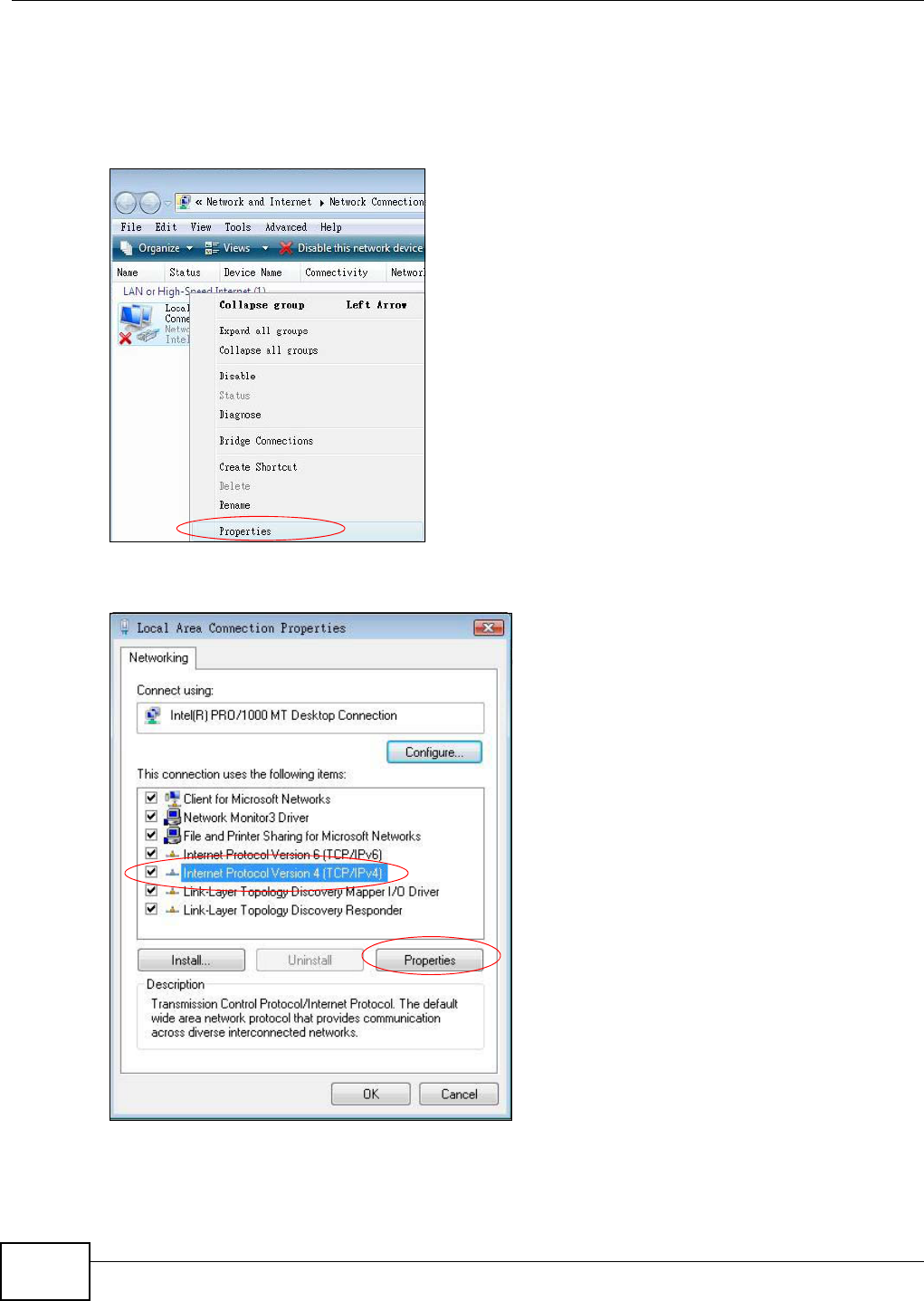
Appendix A Setting up Your Computer’s IP Address
AMG1312-T Series User’s Guide
238
5Right-click Local Area Connection and then click Properties.
Note: During this procedure, click Continue whenever Windows displays a screen saying
that it needs your permission to continue.
Figure 145 Windows Vista: Network and Sharing Center
6Select Internet Protocol Version 4 (TCP/IPv4) and click Properties.
Figure 146 Windows Vista: Local Area Connection Properties
7The Internet Protocol Version 4 (TCP/IPv4) Properties window opens (the General tab).
• If you have a dynamic IP address click Obtain an IP address automatically.
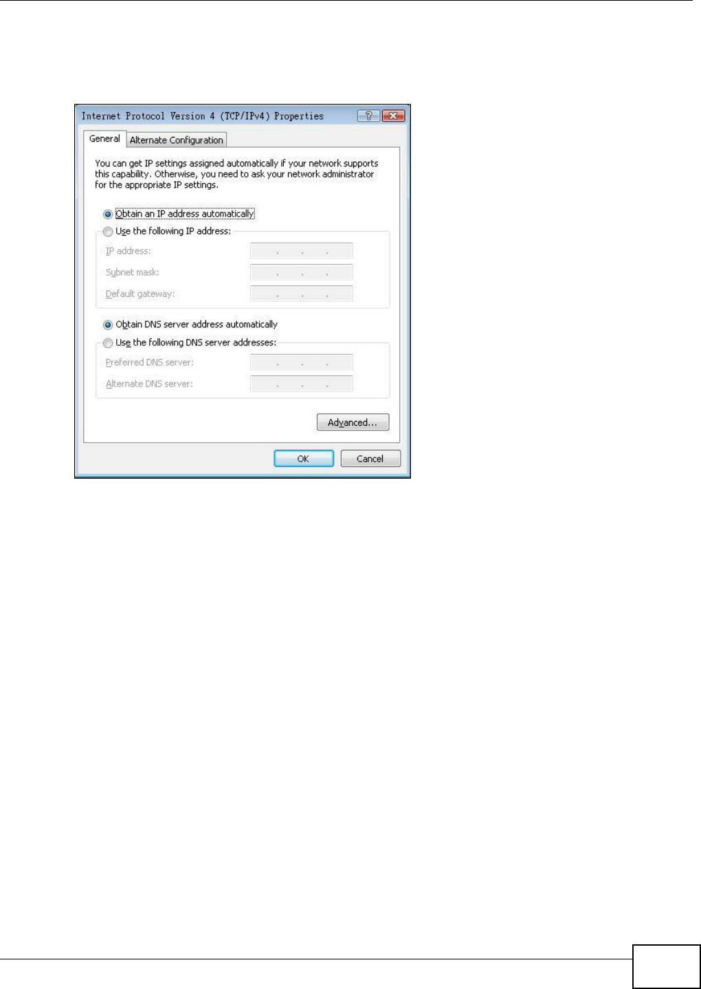
Appendix A Setting up Your Computer’s IP Address
AMG1312-T Series User’s Guide 239
• If you have a static IP address click Use the following IP address and fill in the IP address,
Subnet mask, and Default gateway fields.
• Click Advanced.
Figure 147 Windows Vista: Internet Protocol Version 4 (TCP/IPv4) Properties
8 If you do not know your gateway's IP address, remove any previously installed gateways in the IP
Settings tab and click OK.
Do one or more of the following if you want to configure additional IP addresses:
•In the IP Settings tab, in IP addresses, click Add.
•In TCP/IP Address, type an IP address in IP address and a subnet mask in Subnet mask,
and then click Add.
• Repeat the above two steps for each IP address you want to add.
• Configure additional default gateways in the IP Settings tab by clicking Add in Default
gateways.
•In TCP/IP Gateway Address, type the IP address of the default gateway in Gateway. To
manually configure a default metric (the number of transmission hops), clear the Automatic
metric check box and type a metric in Metric.
• Click Add.
• Repeat the previous three steps for each default gateway you want to add.
• Click OK when finished.
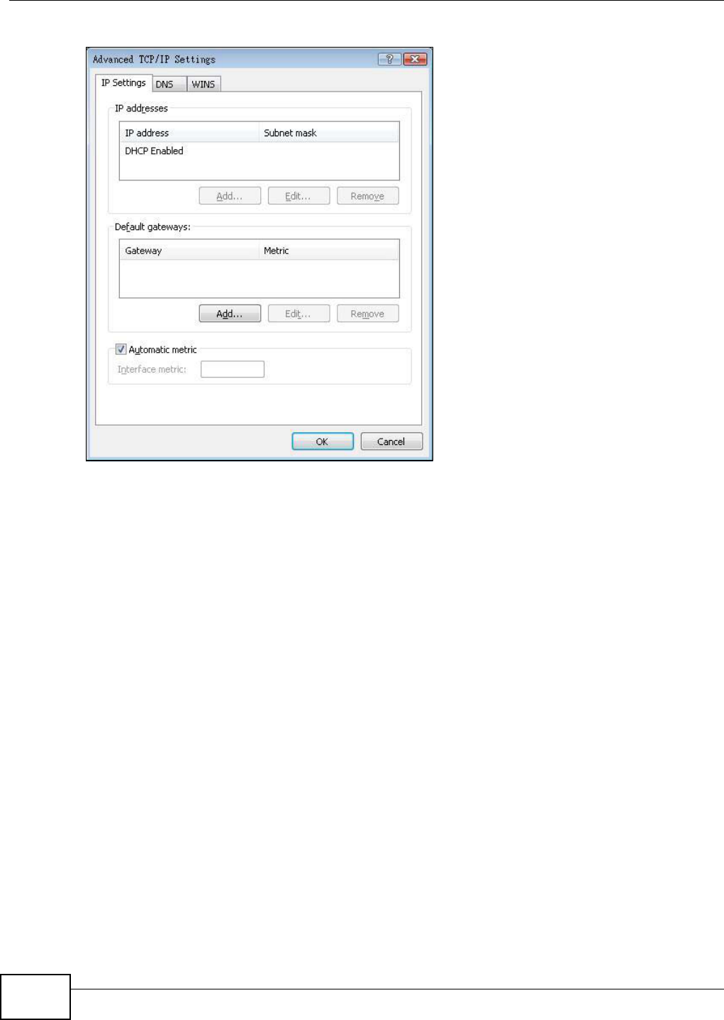
Appendix A Setting up Your Computer’s IP Address
AMG1312-T Series User’s Guide
240
Figure 148 Windows Vista: Advanced TCP/IP Properties
9In the Internet Protocol Version 4 (TCP/IPv4) Properties window, (the General tab):
• Click Obtain DNS server address automatically if you do not know your DNS server IP
address(es).
• If you know your DNS server IP address(es), click Use the following DNS server
addresses, and type them in the Preferred DNS server and Alternate DNS server fields.
If you have previously configured DNS servers, click Advanced and then the DNS tab to order
them.
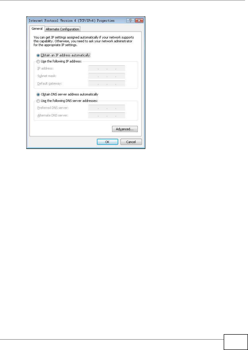
Appendix A Setting up Your Computer’s IP Address
AMG1312-T Series User’s Guide 241
Figure 149 Windows Vista: Internet Protocol Version 4 (TCP/IPv4) Properties
10 Click OK to close the Internet Protocol Version 4 (TCP/IPv4) Properties window.
11 Click Close to close the Local Area Connection Properties window.
12 Close the Network Connections window.
13 Turn on your AMG1312-T Series and restart your computer (if prompted).
Verifying Settings
1Click Start, All Programs, Accessories and then Command Prompt.
2In the Command Prompt window, type "ipconfig" and then press [ENTER]. You can also open
Network Connections, right-click a network connection, click Status and then click the Support
tab.
Macintosh OS 8/9
1Click the Apple menu, Control Panel and double-click TCP/IP to open the TCP/IP Control
Panel.
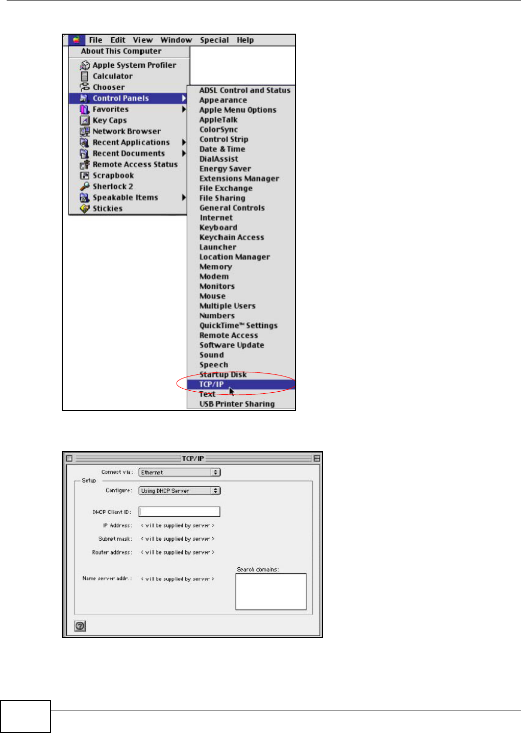
Appendix A Setting up Your Computer’s IP Address
AMG1312-T Series User’s Guide
242
Figure 150 Macintosh OS 8/9: Apple Menu
2Select Ethernet built-in from the Connect via list.
Figure 151 Macintosh OS 8/9: TCP/IP
3For dynamically assigned settings, select Using DHCP Server from the Configure: list.
4For statically assigned settings, do the following:
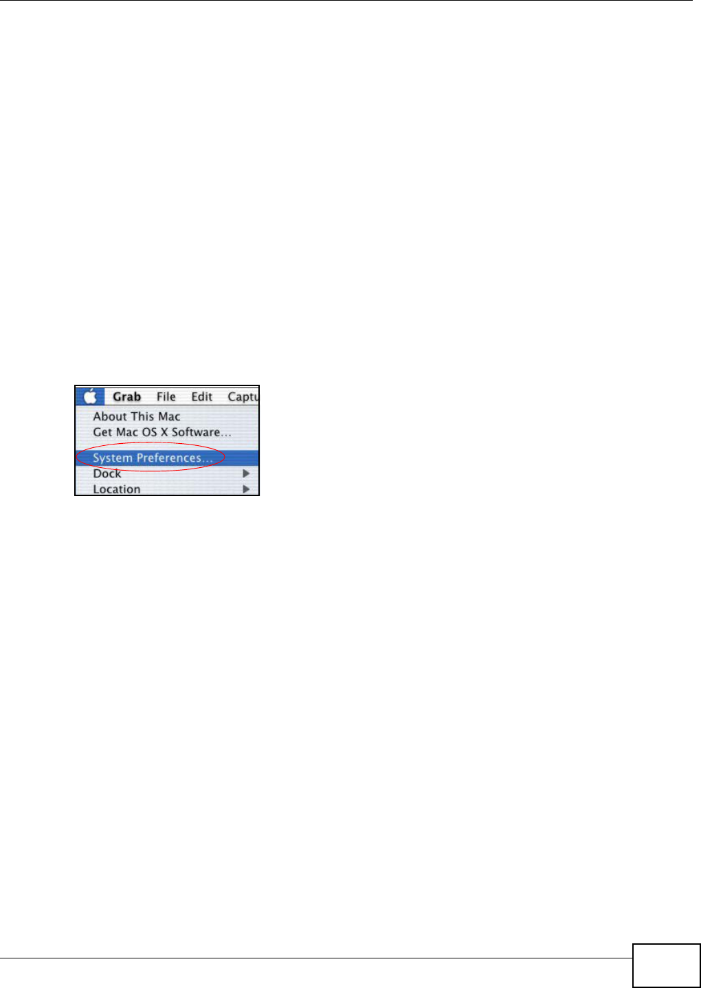
Appendix A Setting up Your Computer’s IP Address
AMG1312-T Series User’s Guide 243
•From the Configure box, select Manually.
• Type your IP address in the IP Address box.
• Type your subnet mask in the Subnet mask box.
• Type the IP address of your AMG1312-T Series in the Router address box.
5Close the TCP/IP Control Panel.
6Click Save if prompted, to save changes to your configuration.
7Turn on your AMG1312-T Series and restart your computer (if prompted).
Verifying Settings
Check your TCP/IP properties in the TCP/IP Control Panel window.
Macintosh OS X
1Click the Apple menu, and click System Preferences to open the System Preferences window.
Figure 152 Macintosh OS X: Apple Menu
2Click Network in the icon bar.
•Select Automatic from the Location list.
•Select Built-in Ethernet from the Show list.
• Click the TCP/IP tab.
3For dynamically assigned settings, select Using DHCP from the Configure list.
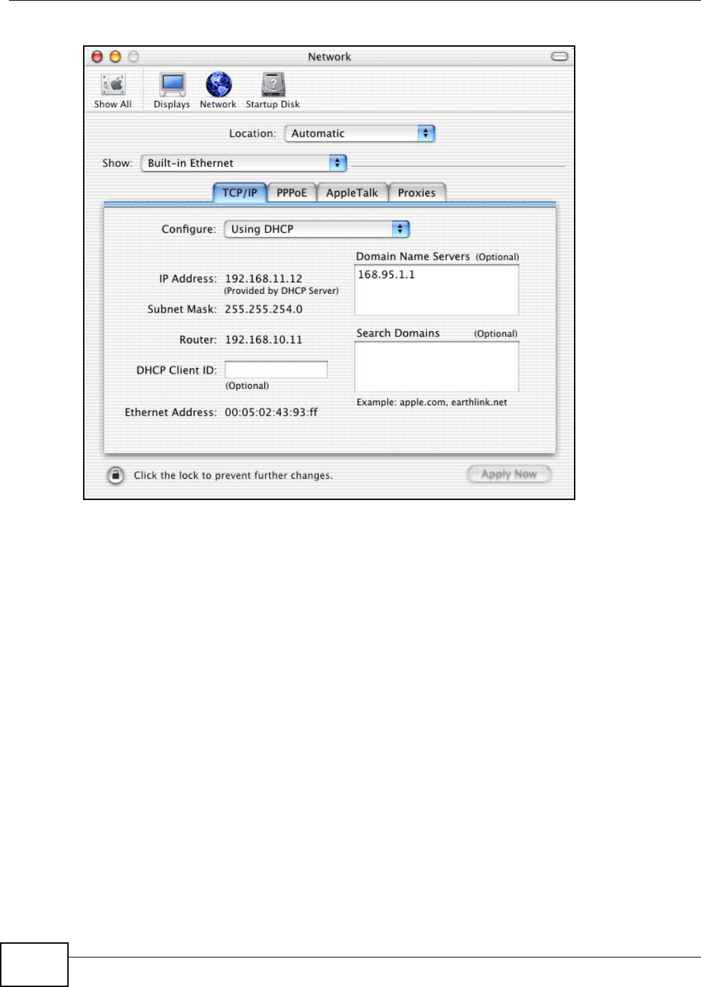
Appendix A Setting up Your Computer’s IP Address
AMG1312-T Series User’s Guide
244
Figure 153 Macintosh OS X: Network
4For statically assigned settings, do the following:
•From the Configure box, select Manually.
• Type your IP address in the IP Address box.
• Type your subnet mask in the Subnet mask box.
• Type the IP address of your AMG1312-T Series in the Router address box.
5Click Apply Now and close the window.
6Turn on your AMG1312-T Series and restart your computer (if prompted).
Verifying Settings
Check your TCP/IP properties in the Network window.
Linux
This section shows you how to configure your computer’s TCP/IP settings in Red Hat Linux 9.0.
Procedure, screens and file location may vary depending on your Linux distribution and release
version.
Note: Make sure you are logged in as the root administrator.
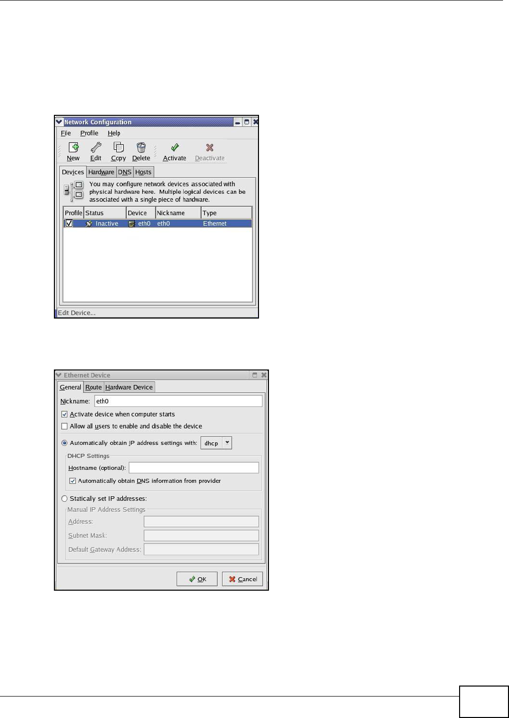
Appendix A Setting up Your Computer’s IP Address
AMG1312-T Series User’s Guide 245
Using the K Desktop Environment (KDE)
Follow the steps below to configure your computer IP address using the KDE.
1Click the Red Hat button (located on the bottom left corner), select System Setting and click
Network.
Figure 154 Red Hat 9.0: KDE: Network Configuration: Devices
2Double-click on the profile of the network card you wish to configure. The Ethernet Device
General screen displays as shown.
Figure 155 Red Hat 9.0: KDE: Ethernet Device: General
• If you have a dynamic IP address, click Automatically obtain IP address settings with and
select dhcp from the drop down list.
• If you have a static IP address, click Statically set IP Addresses and fill in the Address,
Subnet mask, and Default Gateway Address fields.
3Click OK to save the changes and close the Ethernet Device General screen.
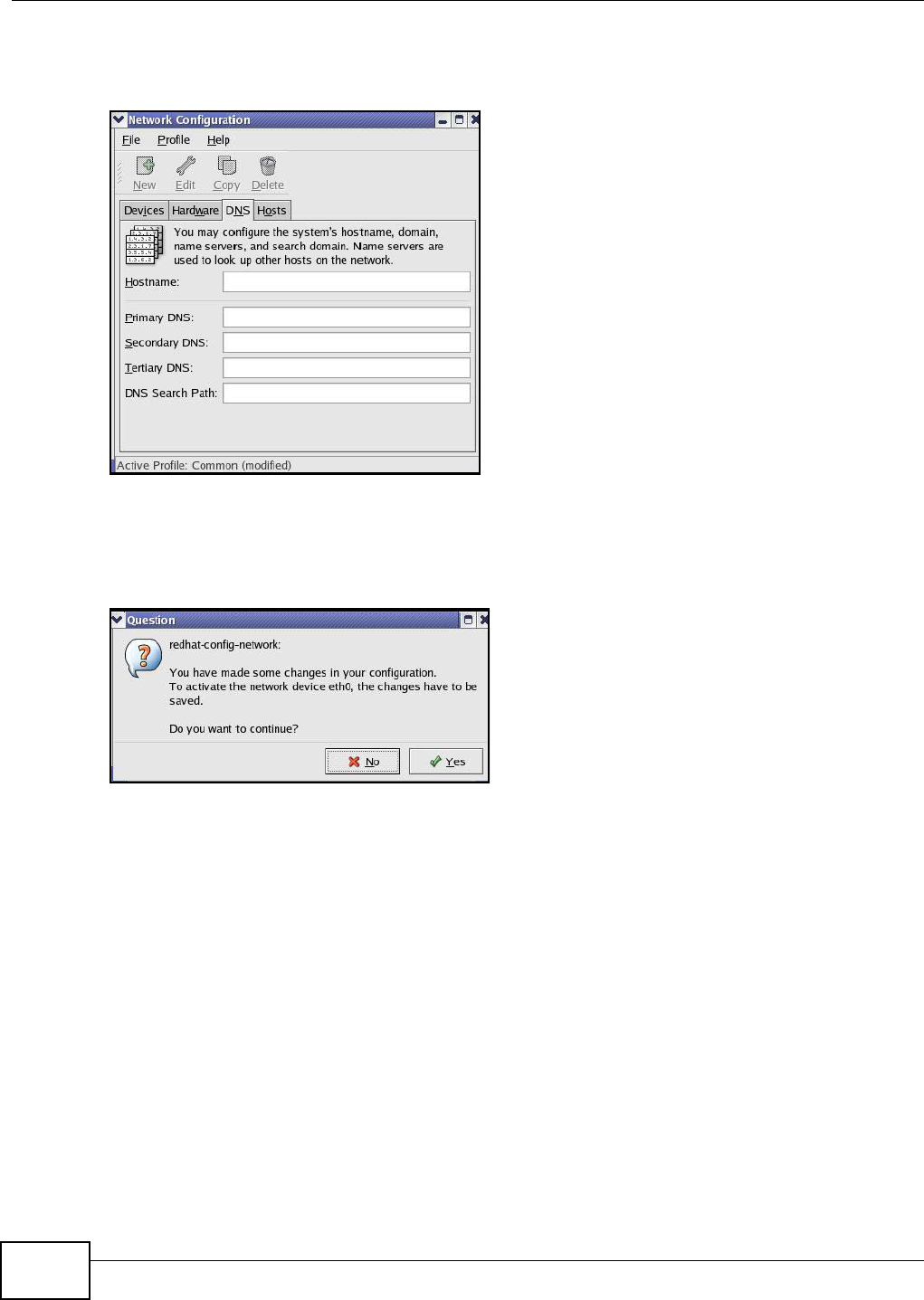
Appendix A Setting up Your Computer’s IP Address
AMG1312-T Series User’s Guide
246
4If you know your DNS server IP address(es), click the DNS tab in the Network Configuration
screen. Enter the DNS server information in the fields provided.
Figure 156 Red Hat 9.0: KDE: Network Configuration: DNS
5Click the Devices tab.
6Click the Activate button to apply the changes. The following screen displays. Click Yes to save
the changes in all screens.
Figure 157 Red Hat 9.0: KDE: Network Configuration: Activate
7After the network card restart process is complete, make sure the Status is Active in the Network
Configuration screen.
Using Configuration Files
Follow the steps below to edit the network configuration files and set your computer IP address.
1Assuming that you have only one network card on the computer, locate the ifconfig-eth0
configuration file (where eth0 is the name of the Ethernet card). Open the configuration file with
any plain text editor.
• If you have a dynamic IP address, enter dhcp in the BOOTPROTO= field. The following figure
shows an example.
Appendix A Setting up Your Computer’s IP Address
AMG1312-T Series User’s Guide 247
Figure 158 Red Hat 9.0: Dynamic IP Address Setting in ifconfig-eth0
• If you have a static IP address, enter static in the BOOTPROTO= field. Type IPADDR= followed
by the IP address (in dotted decimal notation) and type NETMASK= followed by the subnet
mask. The following example shows an example where the static IP address is 192.168.1.10
and the subnet mask is 255.255.255.0.
Figure 159 Red Hat 9.0: Static IP Address Setting in ifconfig-eth0
2If you know your DNS server IP address(es), enter the DNS server information in the resolv.conf
file in the /etc directory. The following figure shows an example where two DNS server IP
addresses are specified.
Figure 160 Red Hat 9.0: DNS Settings in resolv.conf
3After you edit and save the configuration files, you must restart the network card. Enter ./network
restart in the /etc/rc.d/init.d directory. The following figure shows an example.
Figure 161 Red Hat 9.0: Restart Ethernet Card
Verifying Settings
Enter ifconfig in a terminal screen to check your TCP/IP properties.
DEVICE=eth0
ONBOOT=yes
BOOTPROTO=dhcp
USERCTL=no
PEERDNS=yes
TYPE=Ethernet
DEVICE=eth0
ONBOOT=yes
BOOTPROTO=static
IPADDR=192.168.1.10
NETMASK=255.255.255.0
USERCTL=no
PEERDNS=yes
TYPE=Ethernet
nameserver 172.23.5.1
nameserver 172.23.5.2
[root@localhost init.d]# network restart
Shutting down interface eth0: [OK]
Shutting down loopback interface: [OK]
Setting network parameters: [OK]
Bringing up loopback interface: [OK]
Bringing up interface eth0: [OK]

Appendix A Setting up Your Computer’s IP Address
AMG1312-T Series User’s Guide
248
Figure 162 Red Hat 9.0: Checking TCP/IP Properties
[root@localhost]# ifconfig
eth0 Link encap:Ethernet HWaddr 00:50:BA:72:5B:44
inet addr:172.23.19.129 Bcast:172.23.19.255 Mask:255.255.255.0
UP BROADCAST RUNNING MULTICAST MTU:1500 Metric:1
RX packets:717 errors:0 dropped:0 overruns:0 frame:0
TX packets:13 errors:0 dropped:0 overruns:0 carrier:0
collisions:0 txqueuelen:100
RX bytes:730412 (713.2 Kb) TX bytes:1570 (1.5 Kb)
Interrupt:10 Base address:0x1000
[root@localhost]#

AMG1312-T Series User’s Guide 249
APPENDIX B
IP Addresses and Subnetting
This appendix introduces IP addresses and subnet masks.
IP addresses identify individual devices on a network. Every networking device (including
computers, servers, routers, printers, etc.) needs an IP address to communicate across the
network. These networking devices are also known as hosts.
Subnet masks determine the maximum number of possible hosts on a network. You can also use
subnet masks to divide one network into multiple sub-networks.
Introduction to IP Addresses
One part of the IP address is the network number, and the other part is the host ID. In the same
way that houses on a street share a common street name, the hosts on a network share a common
network number. Similarly, as each house has its own house number, each host on the network has
its own unique identifying number - the host ID. Routers use the network number to send packets
to the correct network, while the host ID determines to which host on the network the packets are
delivered.
Structure
An IP address is made up of four parts, written in dotted decimal notation (for example,
192.168.1.1). Each of these four parts is known as an octet. An octet is an eight-digit binary
number (for example 11000000, which is 192 in decimal notation).
Therefore, each octet has a possible range of 00000000 to 11111111 in binary, or 0 to 255 in
decimal.
The following figure shows an example IP address in which the first three octets (192.168.1) are
the network number, and the fourth octet (16) is the host ID.
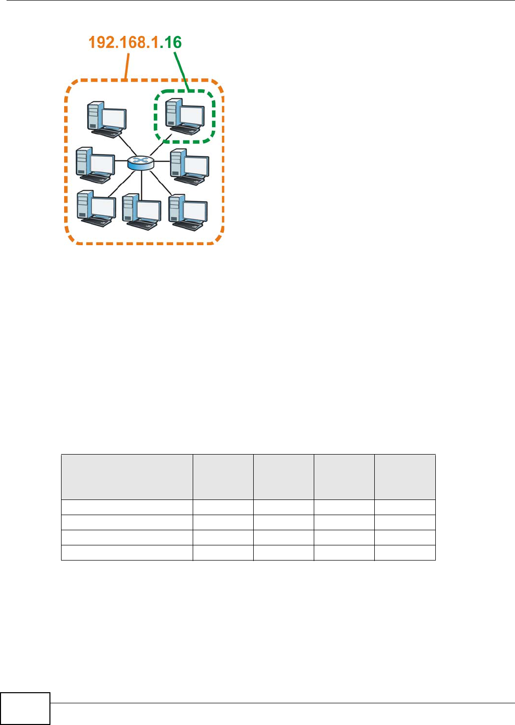
Appendix B IP Addresses and Subnetting
AMG1312-T Series User’s Guide
250
Figure 163 Network Number and Host ID
How much of the IP address is the network number and how much is the host ID varies according
to the subnet mask.
Subnet Masks
A subnet mask is used to determine which bits are part of the network number, and which bits are
part of the host ID (using a logical AND operation). The term “subnet” is short for “sub-network”.
A subnet mask has 32 bits. If a bit in the subnet mask is a “1” then the corresponding bit in the IP
address is part of the network number. If a bit in the subnet mask is “0” then the corresponding bit
in the IP address is part of the host ID.
The following example shows a subnet mask identifying the network number (in bold text) and host
ID of an IP address (192.168.1.2 in decimal).
By convention, subnet masks always consist of a continuous sequence of ones beginning from the
leftmost bit of the mask, followed by a continuous sequence of zeros, for a total number of 32 bits.
Subnet masks can be referred to by the size of the network number part (the bits with a “1” value).
For example, an “8-bit mask” means that the first 8 bits of the mask are ones and the remaining 24
bits are zeroes.
Table 98 Subnet Masks
1ST OCTET:
(192)
2ND
OCTET:
(168)
3RD
OCTET:
(1)
4TH OCTET
(2)
IP Address (Binary) 11000000 10101000 00000001 00000010
Subnet Mask (Binary) 11111111 11111111 11111111 00000000
Network Number 11000000 10101000 00000001
Host ID 00000010
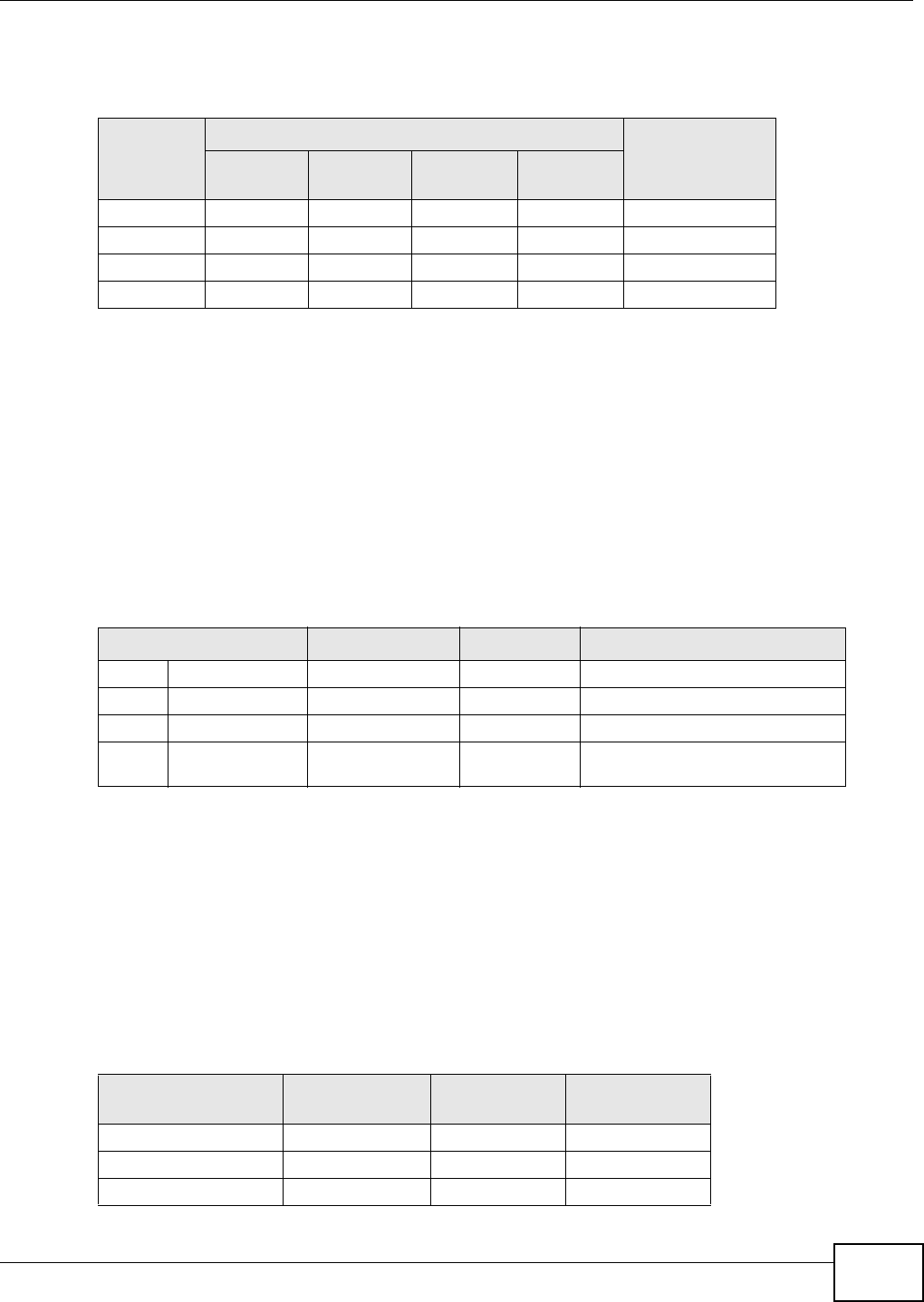
Appendix B IP Addresses and Subnetting
AMG1312-T Series User’s Guide 251
Subnet masks are expressed in dotted decimal notation just like IP addresses. The following
examples show the binary and decimal notation for 8-bit, 16-bit, 24-bit and 29-bit subnet masks.
Network Size
The size of the network number determines the maximum number of possible hosts you can have
on your network. The larger the number of network number bits, the smaller the number of
remaining host ID bits.
An IP address with host IDs of all zeros is the IP address of the network (192.168.1.0 with a 24-bit
subnet mask, for example). An IP address with host IDs of all ones is the broadcast address for that
network (192.168.1.255 with a 24-bit subnet mask, for example).
As these two IP addresses cannot be used for individual hosts, calculate the maximum number of
possible hosts in a network as follows:
Notation
Since the mask is always a continuous number of ones beginning from the left, followed by a
continuous number of zeros for the remainder of the 32 bit mask, you can simply specify the
number of ones instead of writing the value of each octet. This is usually specified by writing a “/”
followed by the number of bits in the mask after the address.
For example, 192.1.1.0 /25 is equivalent to saying 192.1.1.0 with subnet mask 255.255.255.128.
The following table shows some possible subnet masks using both notations.
Table 99 Subnet Masks
BINARY
DECIMAL
1ST
OCTET 2ND
OCTET 3RD
OCTET 4TH OCTET
8-bit mask 11111111 00000000 00000000 00000000 255.0.0.0
16-bit mask 11111111 11111111 00000000 00000000 255.255.0.0
24-bit mask 11111111 11111111 11111111 00000000 255.255.255.0
29-bit mask 11111111 11111111 11111111 11111000 255.255.255.248
Table 100 Maximum Host Numbers
SUBNET MASK HOST ID SIZE MAXIMUM NUMBER OF HOSTS
8 bits 255.0.0.0 24 bits 224 – 2 16777214
16 bits 255.255.0.0 16 bits 216 – 2 65534
24 bits 255.255.255.0 8 bits 28 – 2 254
29 bits 255.255.255.24
8
3 bits 23 – 2 6
Table 101 Alternative Subnet Mask Notation
SUBNET MASK ALTERNATIVE
NOTATION LAST OCTET
(BINARY) LAST OCTET
(DECIMAL)
255.255.255.0 /24 0000 0000 0
255.255.255.128 /25 1000 0000 128
255.255.255.192 /26 1100 0000 192
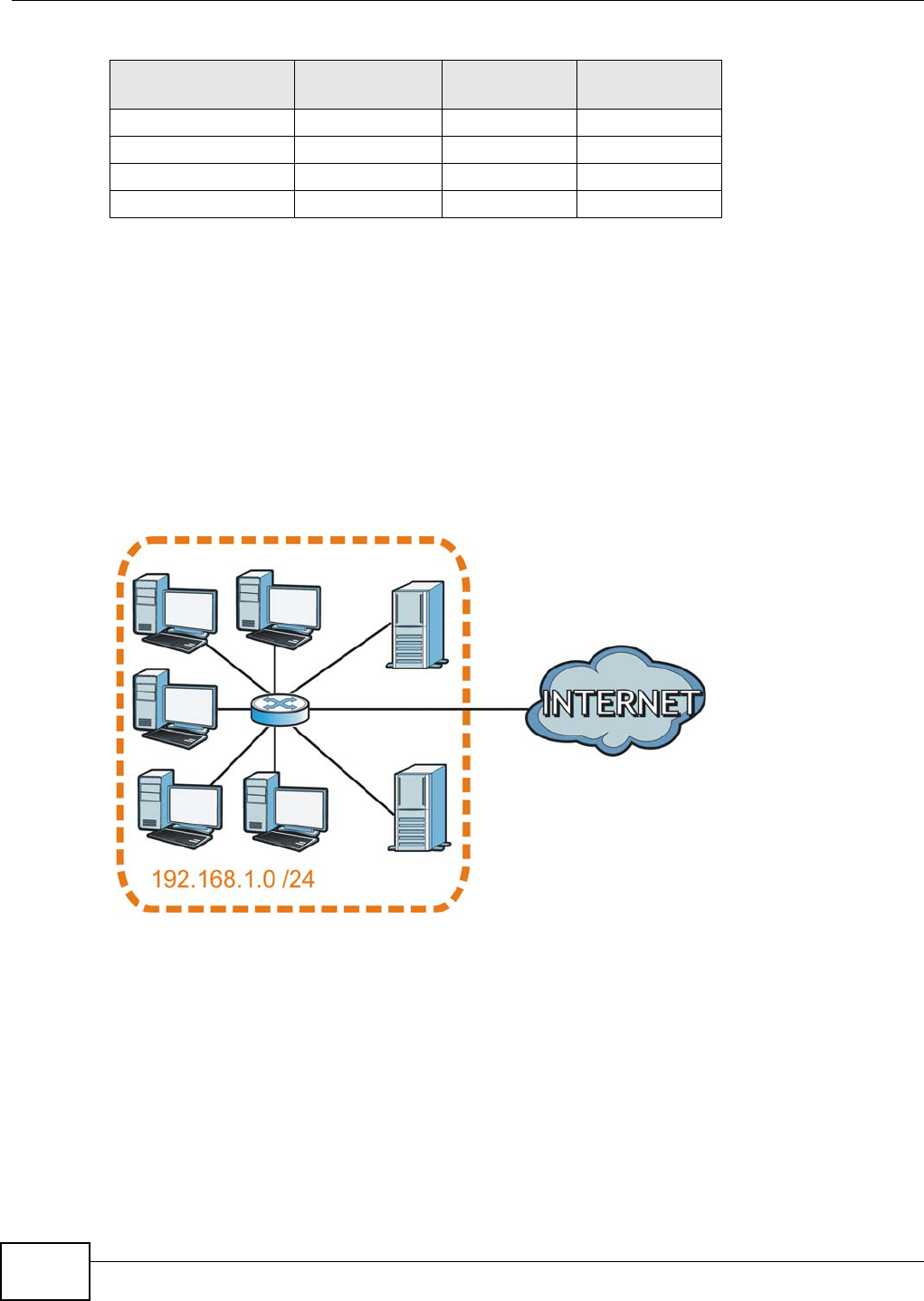
Appendix B IP Addresses and Subnetting
AMG1312-T Series User’s Guide
252
Subnetting
You can use subnetting to divide one network into multiple sub-networks. In the following example
a network administrator creates two sub-networks to isolate a group of servers from the rest of the
company network for security reasons.
In this example, the company network address is 192.168.1.0. The first three octets of the address
(192.168.1) are the network number, and the remaining octet is the host ID, allowing a maximum
of 28 – 2 or 254 possible hosts.
The following figure shows the company network before subnetting.
Figure 164 Subnetting Example: Before Subnetting
You can “borrow” one of the host ID bits to divide the network 192.168.1.0 into two separate sub-
networks. The subnet mask is now 25 bits (255.255.255.128 or /25).
The “borrowed” host ID bit can have a value of either 0 or 1, allowing two subnets; 192.168.1.0 /25
and 192.168.1.128 /25.
The following figure shows the company network after subnetting. There are now two sub-
networks, A and B.
255.255.255.224 /27 1110 0000 224
255.255.255.240 /28 1111 0000 240
255.255.255.248 /29 1111 1000 248
255.255.255.252 /30 1111 1100 252
Table 101 Alternative Subnet Mask Notation (continued)
SUBNET MASK ALTERNATIVE
NOTATION LAST OCTET
(BINARY) LAST OCTET
(DECIMAL)
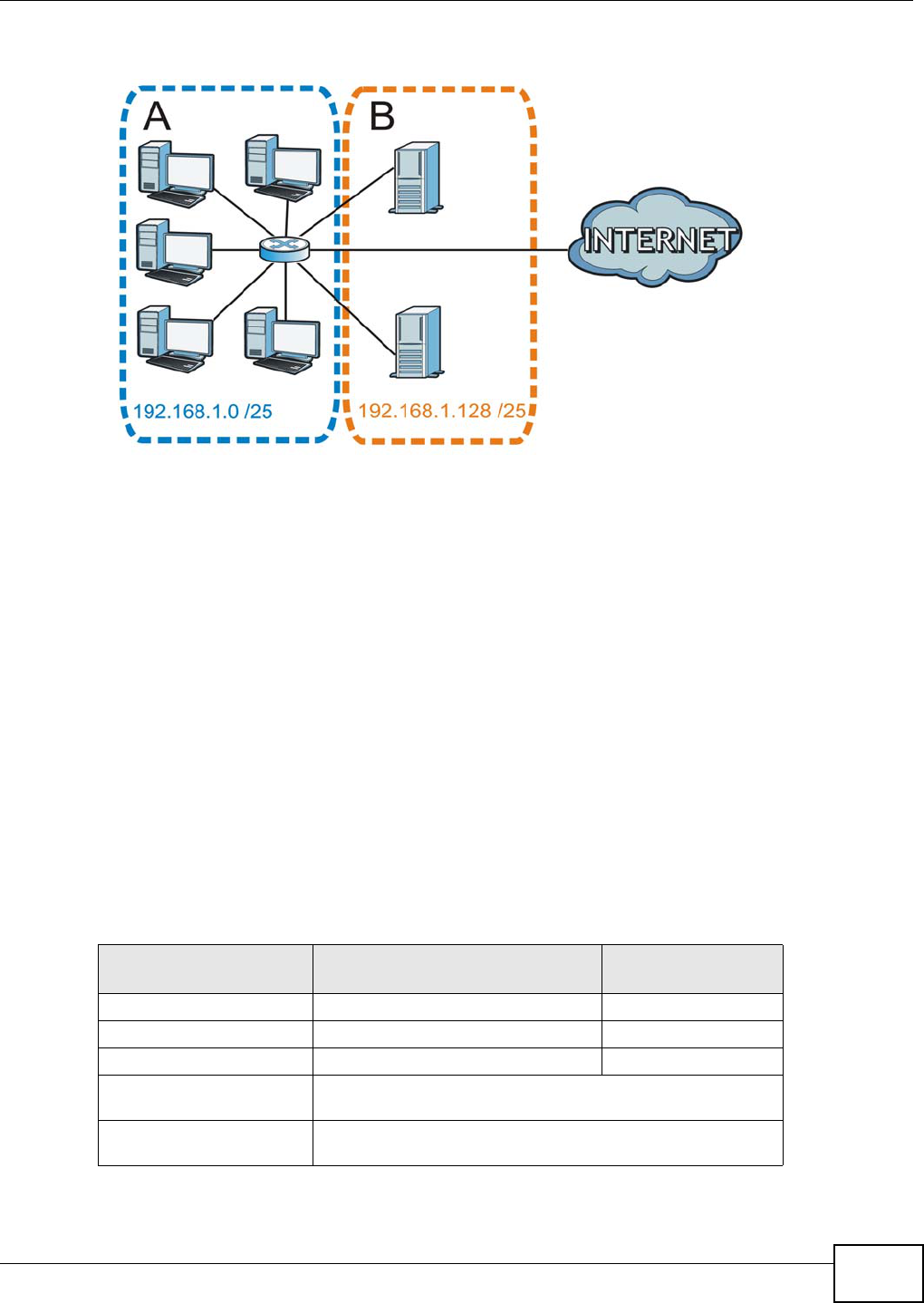
Appendix B IP Addresses and Subnetting
AMG1312-T Series User’s Guide 253
Figure 165 Subnetting Example: After Subnetting
In a 25-bit subnet the host ID has 7 bits, so each sub-network has a maximum of 27 – 2 or 126
possible hosts (a host ID of all zeroes is the subnet’s address itself, all ones is the subnet’s
broadcast address).
192.168.1.0 with mask 255.255.255.128 is subnet A itself, and 192.168.1.127 with mask
255.255.255.128 is its broadcast address. Therefore, the lowest IP address that can be assigned to
an actual host for subnet A is 192.168.1.1 and the highest is 192.168.1.126.
Similarly, the host ID range for subnet B is 192.168.1.129 to 192.168.1.254.
Example: Four Subnets
The previous example illustrated using a 25-bit subnet mask to divide a 24-bit address into two
subnets. Similarly, to divide a 24-bit address into four subnets, you need to “borrow” two host ID
bits to give four possible combinations (00, 01, 10 and 11). The subnet mask is 26 bits
(11111111.11111111.11111111.11000000) or 255.255.255.192.
Each subnet contains 6 host ID bits, giving 26 - 2 or 62 hosts for each subnet (a host ID of all
zeroes is the subnet itself, all ones is the subnet’s broadcast address).
Table 102 Subnet 1
IP/SUBNET MASK NETWORK NUMBER LAST OCTET BIT
VALUE
IP Address (Decimal) 192.168.1. 0
IP Address (Binary) 11000000.10101000.00000001. 00000000
Subnet Mask (Binary) 11111111.11111111.11111111. 11000000
Subnet Address:
192.168.1.0
Lowest Host ID: 192.168.1.1
Broadcast Address:
192.168.1.63
Highest Host ID: 192.168.1.62
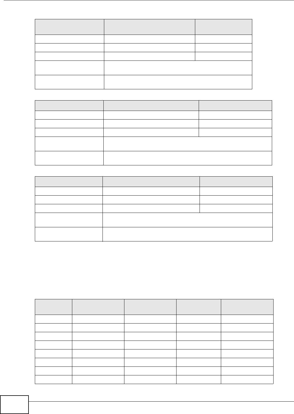
Appendix B IP Addresses and Subnetting
AMG1312-T Series User’s Guide
254
Example: Eight Subnets
Similarly, use a 27-bit mask to create eight subnets (000, 001, 010, 011, 100, 101, 110 and 111).
The following table shows IP address last octet values for each subnet.
Table 103 Subnet 2
IP/SUBNET MASK NETWORK NUMBER LAST OCTET BIT
VALUE
IP Address 192.168.1. 64
IP Address (Binary) 11000000.10101000.00000001. 01000000
Subnet Mask (Binary) 11111111.11111111.11111111. 11000000
Subnet Address:
192.168.1.64
Lowest Host ID: 192.168.1.65
Broadcast Address:
192.168.1.127
Highest Host ID: 192.168.1.126
Table 104 Subnet 3
IP/SUBNET MASK NETWORK NUMBER LAST OCTET BIT VALUE
IP Address 192.168.1. 128
IP Address (Binary) 11000000.10101000.00000001. 10000000
Subnet Mask (Binary) 11111111.11111111.11111111. 11000000
Subnet Address:
192.168.1.128
Lowest Host ID: 192.168.1.129
Broadcast Address:
192.168.1.191
Highest Host ID: 192.168.1.190
Table 105 Subnet 4
IP/SUBNET MASK NETWORK NUMBER LAST OCTET BIT VALUE
IP Address 192.168.1. 192
IP Address (Binary) 11000000.10101000.00000001. 11000000
Subnet Mask (Binary) 11111111.11111111.11111111. 11000000
Subnet Address:
192.168.1.192
Lowest Host ID: 192.168.1.193
Broadcast Address:
192.168.1.255
Highest Host ID: 192.168.1.254
Table 106 Eight Subnets
SUBNET SUBNET
ADDRESS FIRST ADDRESS LAST
ADDRESS BROADCAST
ADDRESS
1 0 1 30 31
232 33 62 63
364 65 94 95
496 97 126 127
5128 129 158 159
6160 161 190 191
7192 193 222 223
8224 225 254 255
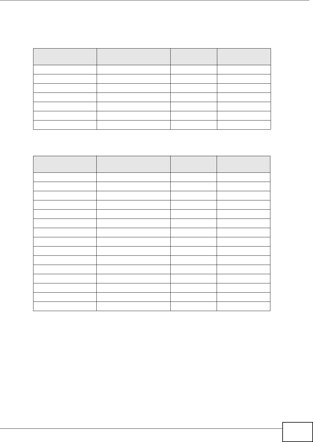
Appendix B IP Addresses and Subnetting
AMG1312-T Series User’s Guide 255
Subnet Planning
The following table is a summary for subnet planning on a network with a 24-bit network number.
The following table is a summary for subnet planning on a network with a 16-bit network number.
Configuring IP Addresses
Where you obtain your network number depends on your particular situation. If the ISP or your
network administrator assigns you a block of registered IP addresses, follow their instructions in
selecting the IP addresses and the subnet mask.
If the ISP did not explicitly give you an IP network number, then most likely you have a single user
account and the ISP will assign you a dynamic IP address when the connection is established. If this
is the case, it is recommended that you select a network number from 192.168.0.0 to
192.168.255.0. The Internet Assigned Number Authority (IANA) reserved this block of addresses
specifically for private use; please do not use any other number unless you are told otherwise. You
must also enable Network Address Translation (NAT) on the AMG1312-T Series.
Table 107 24-bit Network Number Subnet Planning
NO. “BORROWED”
HOST BITS SUBNET MASK NO. SUBNETS NO. HOSTS PER
SUBNET
1255.255.255.128 (/25) 2126
2255.255.255.192 (/26) 462
3255.255.255.224 (/27) 830
4255.255.255.240 (/28) 16 14
5255.255.255.248 (/29) 32 6
6255.255.255.252 (/30) 64 2
7255.255.255.254 (/31) 128 1
Table 108 16-bit Network Number Subnet Planning
NO. “BORROWED”
HOST BITS SUBNET MASK NO. SUBNETS NO. HOSTS PER
SUBNET
1255.255.128.0 (/17) 232766
2255.255.192.0 (/18) 416382
3255.255.224.0 (/19) 88190
4255.255.240.0 (/20) 16 4094
5255.255.248.0 (/21) 32 2046
6255.255.252.0 (/22) 64 1022
7255.255.254.0 (/23) 128 510
8255.255.255.0 (/24) 256 254
9255.255.255.128 (/25) 512 126
10 255.255.255.192 (/26) 1024 62
11 255.255.255.224 (/27) 2048 30
12 255.255.255.240 (/28) 4096 14
13 255.255.255.248 (/29) 8192 6
14 255.255.255.252 (/30) 16384 2
15 255.255.255.254 (/31) 32768 1

Appendix B IP Addresses and Subnetting
AMG1312-T Series User’s Guide
256
Once you have decided on the network number, pick an IP address for your AMG1312-T Series that
is easy to remember (for instance, 192.168.1.1) but make sure that no other device on your
network is using that IP address.
The subnet mask specifies the network number portion of an IP address. Your AMG1312-T Series
will compute the subnet mask automatically based on the IP address that you entered. You don't
need to change the subnet mask computed by the AMG1312-T Series unless you are instructed to
do otherwise.
Private IP Addresses
Every machine on the Internet must have a unique address. If your networks are isolated from the
Internet (running only between two branch offices, for example) you can assign any IP addresses to
the hosts without problems. However, the Internet Assigned Numbers Authority (IANA) has
reserved the following three blocks of IP addresses specifically for private networks:
• 10.0.0.0 — 10.255.255.255
• 172.16.0.0 — 172.31.255.255
• 192.168.0.0 — 192.168.255.255
You can obtain your IP address from the IANA, from an ISP, or it can be assigned from a private
network. If you belong to a small organization and your Internet access is through an ISP, the ISP
can provide you with the Internet addresses for your local networks. On the other hand, if you are
part of a much larger organization, you should consult your network administrator for the
appropriate IP addresses.
Regardless of your particular situation, do not create an arbitrary IP address; always follow the
guidelines above. For more information on address assignment, please refer to RFC 1597, Address
Allocation for Private Internets and RFC 1466, Guidelines for Management of IP Address Space.
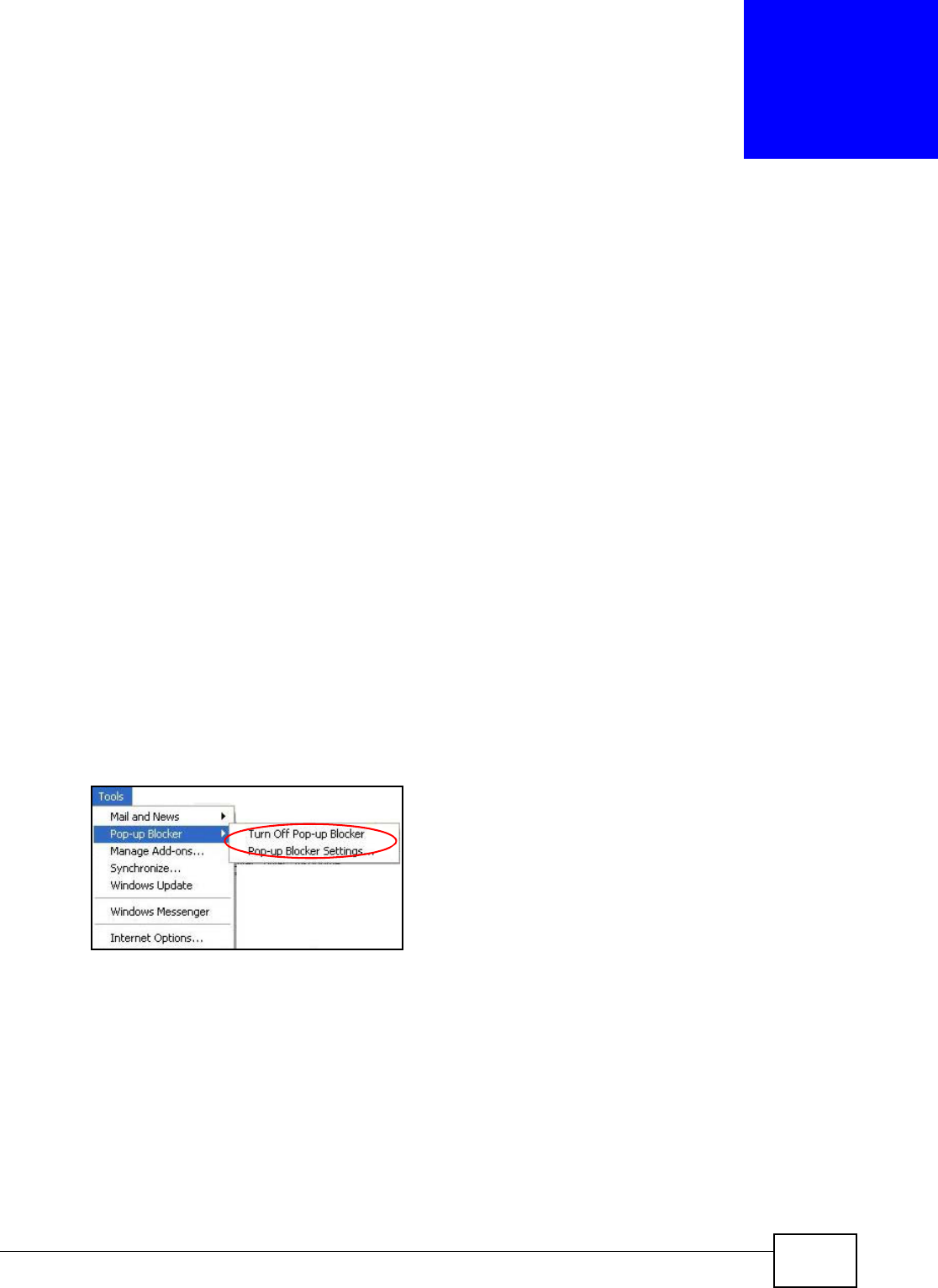
AMG1312-T Series User’s Guide 257
APPENDIX C
Pop-up Windows, JavaScripts and Java
Permissions
In order to use the web configurator you need to allow:
• Web browser pop-up windows from your device.
• JavaScripts (enabled by default).
• Java permissions (enabled by default).
Note: Internet Explorer 6 screens are used here. Screens for other Internet Explorer
versions may vary.
Internet Explorer Pop-up Blockers
You may have to disable pop-up blocking to log into your device.
Either disable pop-up blocking (enabled by default in Windows XP SP (Service Pack) 2) or allow
pop-up blocking and create an exception for your device’s IP address.
Disable Pop-up Blockers
1In Internet Explorer, select Tools, Pop-up Blocker and then select Turn Off Pop-up Blocker.
Figure 166 Pop-up Blocker
You can also check if pop-up blocking is disabled in the Pop-up Blocker section in the Privacy tab.
1In Internet Explorer, select Tools, Internet Options, Privacy.
2Clear the Block pop-ups check box in the Pop-up Blocker section of the screen. This disables any
web pop-up blockers you may have enabled.
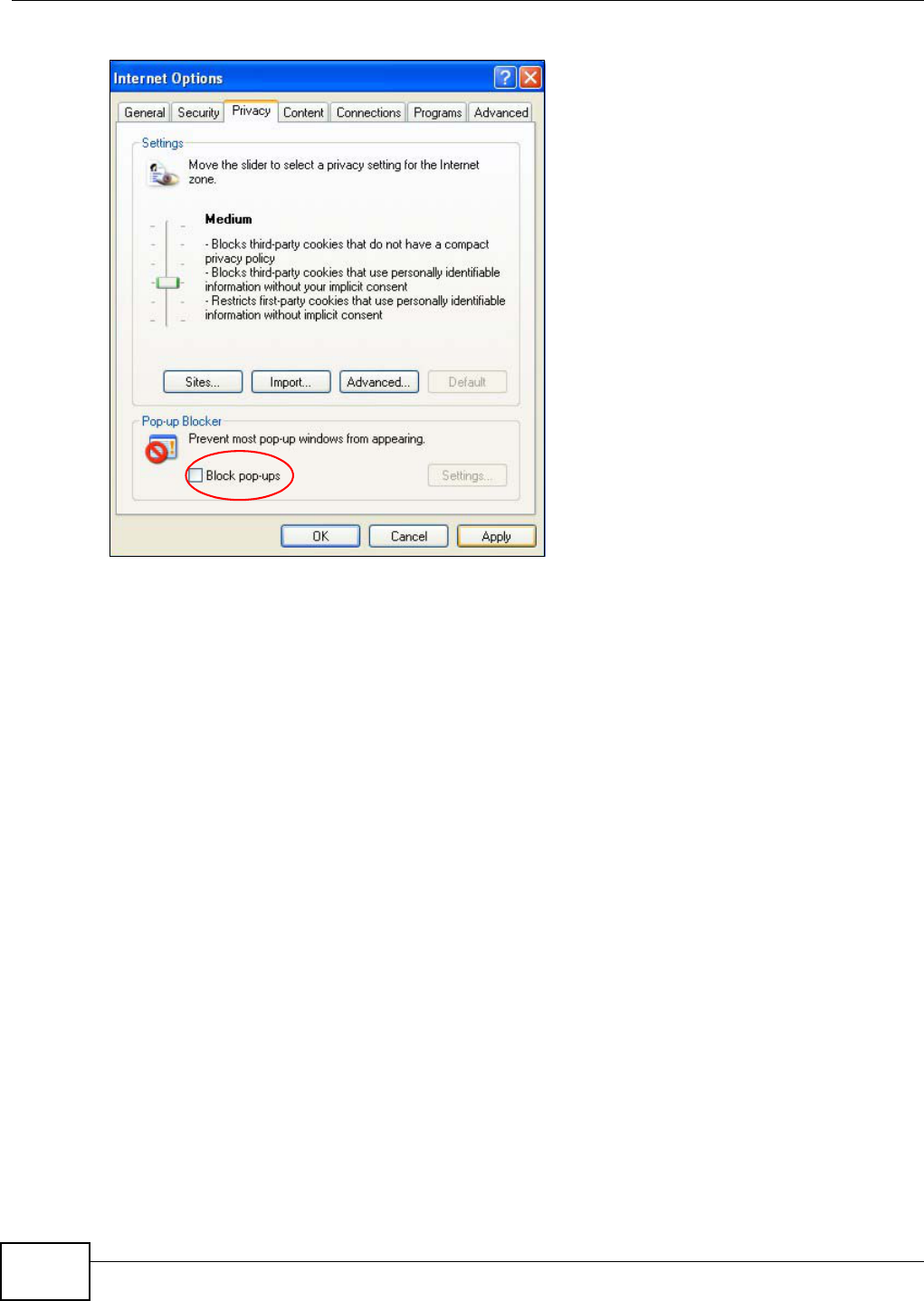
Appendix C Pop-up Windows, JavaScripts and Java Permissions
AMG1312-T Series User’s Guide
258
Figure 167 Internet Options: Privacy
3Click Apply to save this setting.
Enable Pop-up Blockers with Exceptions
Alternatively, if you only want to allow pop-up windows from your device, see the following steps.
1In Internet Explorer, select Tools, Internet Options and then the Privacy tab.
2Select Settings…to open the Pop-up Blocker Settings screen.
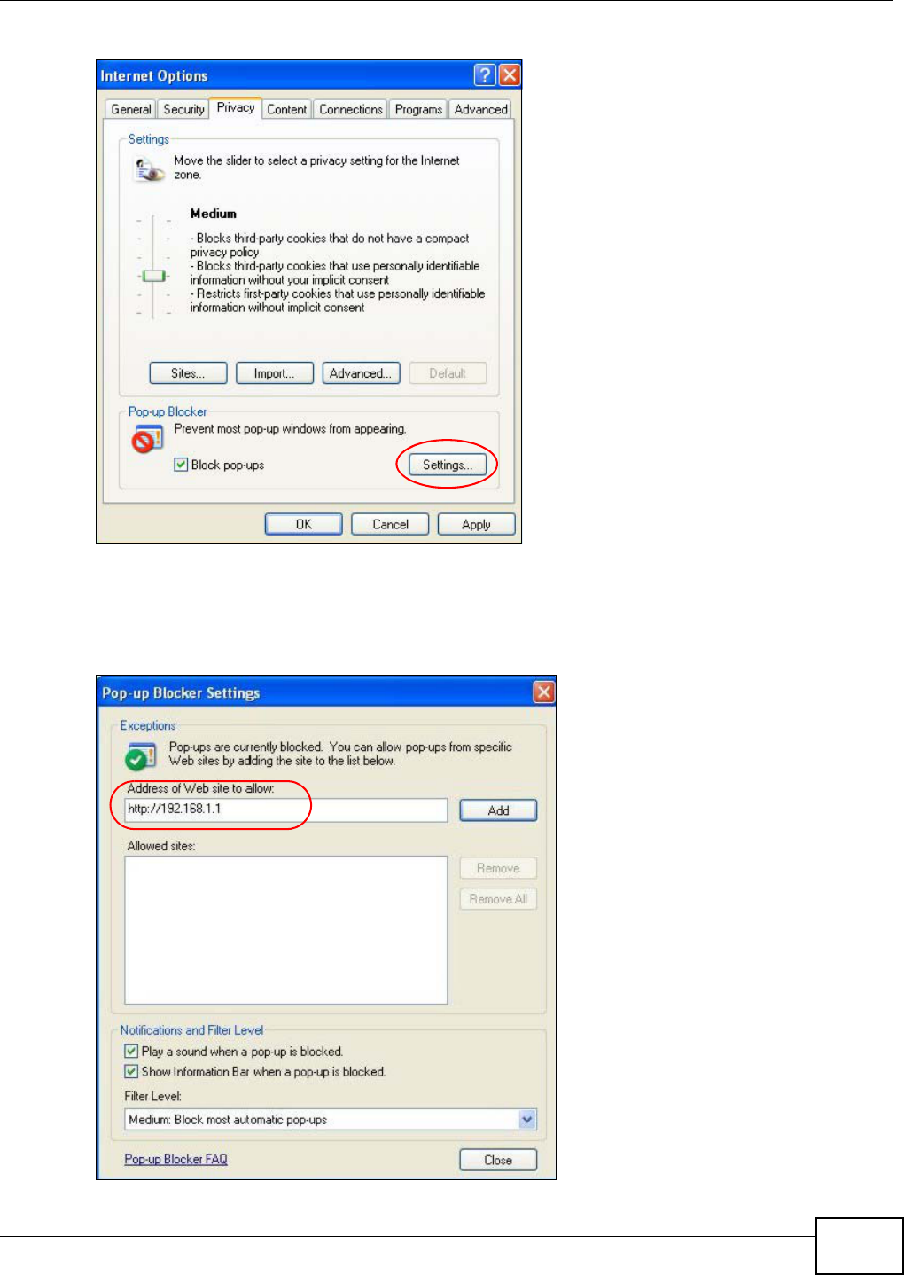
Appendix C Pop-up Windows, JavaScripts and Java Permissions
AMG1312-T Series User’s Guide 259
Figure 168 Internet Options: Privacy
3Type the IP address of your device (the web page that you do not want to have blocked) with the
prefix “http://”. For example, http://192.168.167.1.
4Click Add to move the IP address to the list of Allowed sites.
Figure 169 Pop-up Blocker Settings
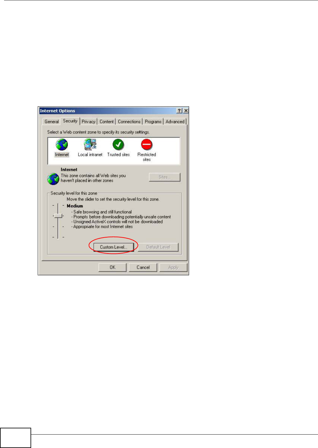
Appendix C Pop-up Windows, JavaScripts and Java Permissions
AMG1312-T Series User’s Guide
260
5Click Close to return to the Privacy screen.
6Click Apply to save this setting.
JavaScripts
If pages of the web configurator do not display properly in Internet Explorer, check that JavaScripts
are allowed.
1In Internet Explorer, click Tools, Internet Options and then the Security tab.
Figure 170 Internet Options: Security
2Click the Custom Level... button.
3Scroll down to Scripting.
4Under Active scripting make sure that Enable is selected (the default).
5Under Scripting of Java applets make sure that Enable is selected (the default).
6Click OK to close the window.
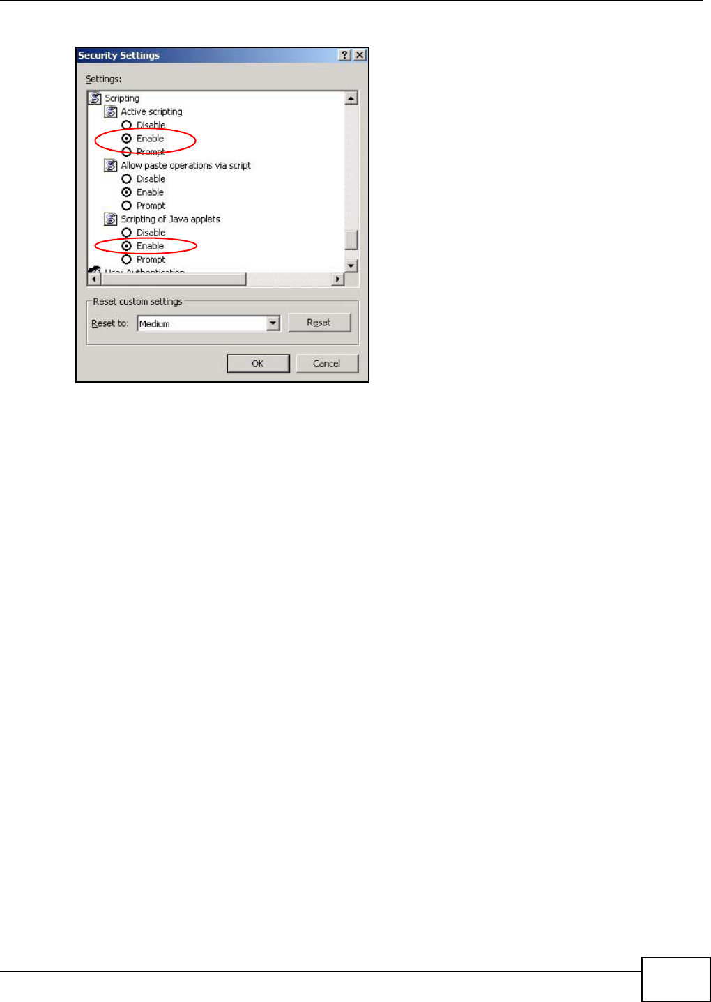
Appendix C Pop-up Windows, JavaScripts and Java Permissions
AMG1312-T Series User’s Guide 261
Figure 171 Security Settings - Java Scripting
Java Permissions
1From Internet Explorer, click Tools, Internet Options and then the Security tab.
2Click the Custom Level... button.
3Scroll down to Microsoft VM.
4Under Java permissions make sure that a safety level is selected.
5Click OK to close the window.
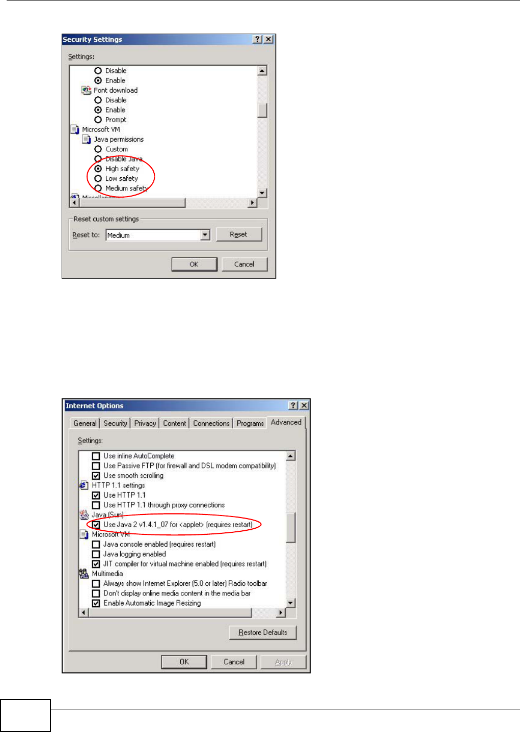
Appendix C Pop-up Windows, JavaScripts and Java Permissions
AMG1312-T Series User’s Guide
262
Figure 172 Security Settings - Java
JAVA (Sun)
1From Internet Explorer, click Tools, Internet Options and then the Advanced tab.
2Make sure that Use Java 2 for <applet> under Java (Sun) is selected.
3Click OK to close the window.
Figure 173 Java (Sun)
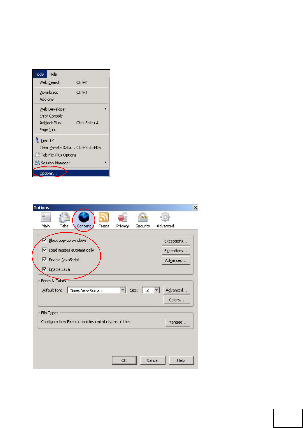
Appendix C Pop-up Windows, JavaScripts and Java Permissions
AMG1312-T Series User’s Guide 263
Mozilla Firefox
Mozilla Firefox 2.0 screens are used here. Screens for other versions may vary.
You can enable Java, Javascripts and pop-ups in one screen. Click Tools, then click Options in the
screen that appears.
Figure 174 Mozilla Firefox: Tools > Options
Click Content to show the screen below. Select the check boxes as shown in the following screen.
Figure 175 Mozilla Firefox Content Security
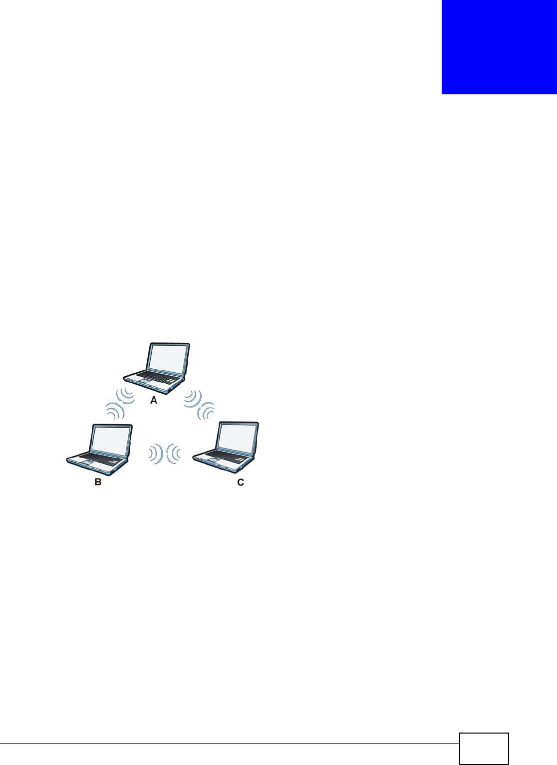
AMG1312-T Series User’s Guide 264
APPENDIX D
Wireless LANs
Wireless LAN Topologies
This section discusses ad-hoc and infrastructure wireless LAN topologies.
Ad-hoc Wireless LAN Configuration
The simplest WLAN configuration is an independent (Ad-hoc) WLAN that connects a set of
computers with wireless adapters (A, B, C). Any time two or more wireless adapters are within
range of each other, they can set up an independent network, which is commonly referred to as an
ad-hoc network or Independent Basic Service Set (IBSS). The following diagram shows an example
of notebook computers using wireless adapters to form an ad-hoc wireless LAN.
Figure 176 Peer-to-Peer Communication in an Ad-hoc Network
BSS
A Basic Service Set (BSS) exists when all communications between wireless clients or between a
wireless client and a wired network client go through one access point (AP).
Intra-BSS traffic is traffic between wireless clients in the BSS. When Intra-BSS is enabled, wireless
client A and B can access the wired network and communicate with each other. When Intra-BSS is
disabled, wireless client A and B can still access the wired network but cannot communicate with
each other.
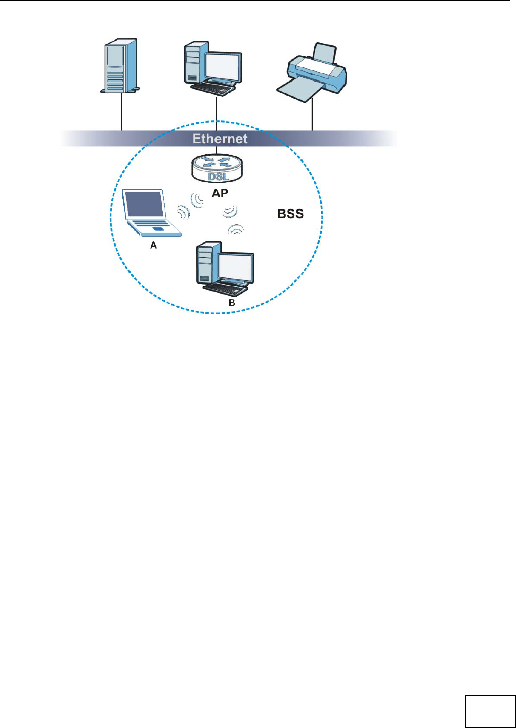
Appendix D Wireless LANs
AMG1312-T Series User’s Guide 265
Figure 177 Basic Service Set
ESS
An Extended Service Set (ESS) consists of a series of overlapping BSSs, each containing an access
point, with each access point connected together by a wired network. This wired connection
between APs is called a Distribution System (DS).
This type of wireless LAN topology is called an Infrastructure WLAN. The Access Points not only
provide communication with the wired network but also mediate wireless network traffic in the
immediate neighborhood.
An ESSID (ESS IDentification) uniquely identifies each ESS. All access points and their associated
wireless clients within the same ESS must have the same ESSID in order to communicate.
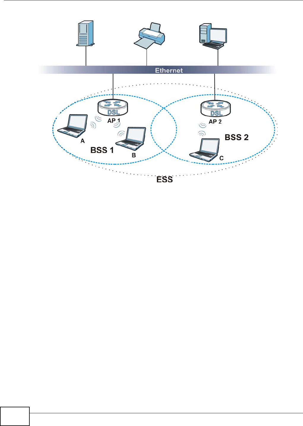
Appendix D Wireless LANs
AMG1312-T Series User’s Guide
266
Figure 178 Infrastructure WLAN
Channel
A channel is the radio frequency(ies) used by wireless devices to transmit and receive data.
Channels available depend on your geographical area. You may have a choice of channels (for your
region) so you should use a channel different from an adjacent AP (access point) to reduce
interference. Interference occurs when radio signals from different access points overlap causing
interference and degrading performance.
Adjacent channels partially overlap however. To avoid interference due to overlap, your AP should
be on a channel at least five channels away from a channel that an adjacent AP is using. For
example, if your region has 11 channels and an adjacent AP is using channel 1, then you need to
select a channel between 6 or 11.
RTS/CTS
A hidden node occurs when two stations are within range of the same access point, but are not
within range of each other. The following figure illustrates a hidden node. Both stations (STA) are
within range of the access point (AP) or wireless gateway, but out-of-range of each other, so they
cannot "hear" each other, that is they do not know if the channel is currently being used. Therefore,
they are considered hidden from each other.
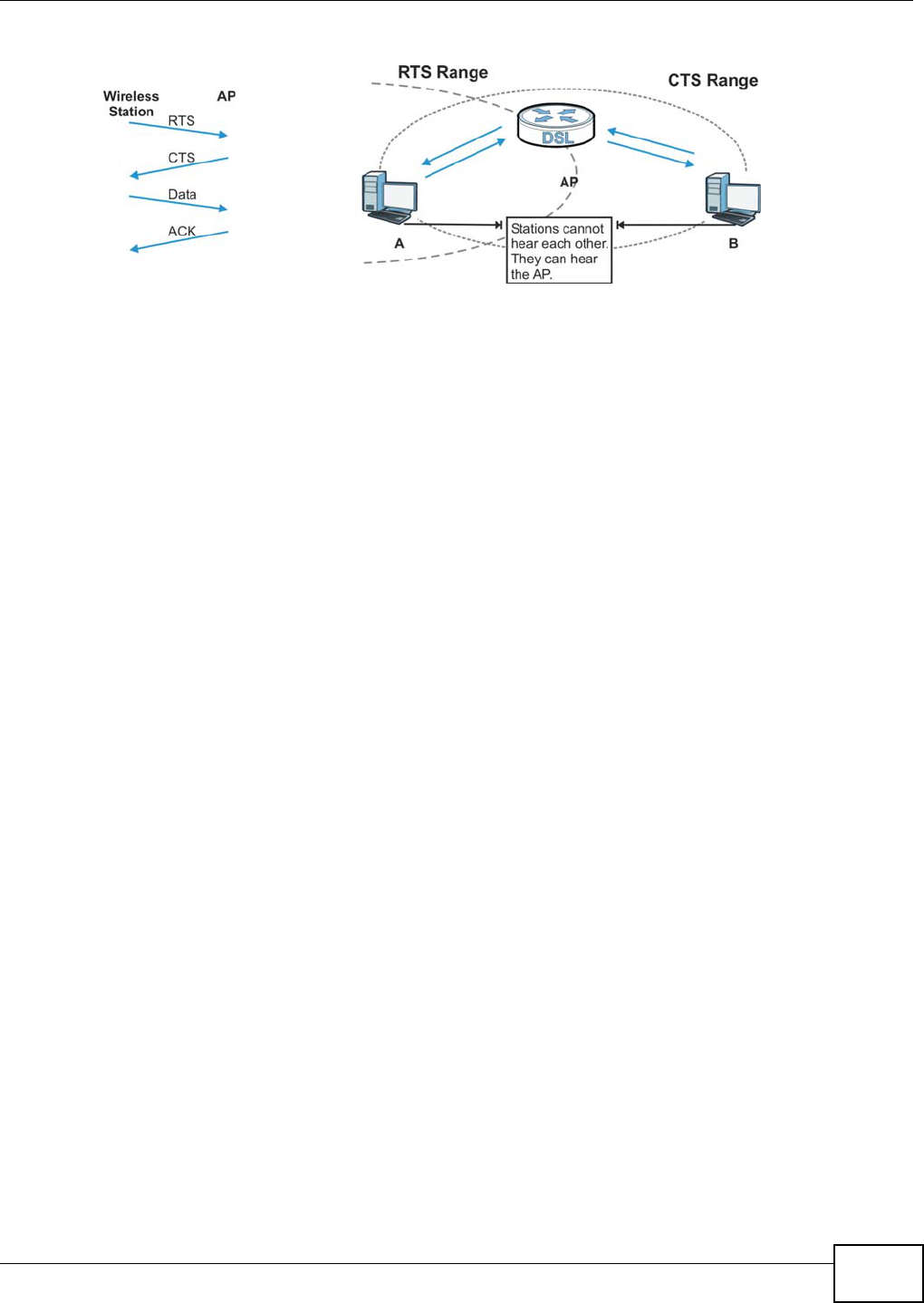
Appendix D Wireless LANs
AMG1312-T Series User’s Guide 267
Figure 179 RTS/CTS
When station A sends data to the AP, it might not know that the station B is already using the
channel. If these two stations send data at the same time, collisions may occur when both sets of
data arrive at the AP at the same time, resulting in a loss of messages for both stations.
RTS/CTS is designed to prevent collisions due to hidden nodes. An RTS/CTS defines the biggest
size data frame you can send before an RTS (Request To Send)/CTS (Clear to Send) handshake is
invoked.
When a data frame exceeds the RTS/CTS value you set (between 0 to 2432 bytes), the station
that wants to transmit this frame must first send an RTS (Request To Send) message to the AP for
permission to send it. The AP then responds with a CTS (Clear to Send) message to all other
stations within its range to notify them to defer their transmission. It also reserves and confirms
with the requesting station the time frame for the requested transmission.
Stations can send frames smaller than the specified RTS/CTS directly to the AP without the RTS
(Request To Send)/CTS (Clear to Send) handshake.
You should only configure RTS/CTS if the possibility of hidden nodes exists on your network and
the "cost" of resending large frames is more than the extra network overhead involved in the RTS
(Request To Send)/CTS (Clear to Send) handshake.
If the RTS/CTS value is greater than the Fragmentation Threshold value (see next), then the
RTS (Request To Send)/CTS (Clear to Send) handshake will never occur as data frames will be
fragmented before they reach RTS/CTS size.
Note: Enabling the RTS Threshold causes redundant network overhead that could
negatively affect the throughput performance instead of providing a remedy.
Fragmentation Threshold
A Fragmentation Threshold is the maximum data fragment size (between 256 and 2432 bytes)
that can be sent in the wireless network before the AP will fragment the packet into smaller data
frames.
A large Fragmentation Threshold is recommended for networks not prone to interference while
you should set a smaller threshold for busy networks or networks that are prone to interference.
If the Fragmentation Threshold value is smaller than the RTS/CTS value (see previously) you
set then the RTS (Request To Send)/CTS (Clear to Send) handshake will never occur as data frames
will be fragmented before they reach RTS/CTS size.
Appendix D Wireless LANs
AMG1312-T Series User’s Guide
268
Preamble Type
Preamble is used to signal that data is coming to the receiver. Short and long refer to the length of
the synchronization field in a packet.
Short preamble increases performance as less time sending preamble means more time for sending
data. All IEEE 802.11 compliant wireless adapters support long preamble, but not all support short
preamble.
Use long preamble if you are unsure what preamble mode other wireless devices on the network
support, and to provide more reliable communications in busy wireless networks.
Use short preamble if you are sure all wireless devices on the network support it, and to provide
more efficient communications.
Use the dynamic setting to automatically use short preamble when all wireless devices on the
network support it, otherwise the AMG1312-T Series uses long preamble.
Note: The wireless devices MUST use the same preamble mode in order to communicate.
IEEE 802.11g Wireless LAN
IEEE 802.11g is fully compatible with the IEEE 802.11b standard. This means an IEEE 802.11b
adapter can interface directly with an IEEE 802.11g access point (and vice versa) at 11 Mbps or
lower depending on range. IEEE 802.11g has several intermediate rate steps between the
maximum and minimum data rates. The IEEE 802.11g data rate and modulation are as follows:
Wireless Security Overview
Wireless security is vital to your network to protect wireless communication between wireless
clients, access points and the wired network.
Wireless security methods available on the AMG1312-T Series are data encryption, wireless client
authentication, restricting access by device MAC address and hiding the AMG1312-T Series identity.
Table 109 IEEE 802.11g
DATA RATE (MBPS) MODULATION
1 DBPSK (Differential Binary Phase Shift Keyed)
2 DQPSK (Differential Quadrature Phase Shift Keying)
5.5 / 11 CCK (Complementary Code Keying)
6/9/12/18/24/36/48/
54
OFDM (Orthogonal Frequency Division Multiplexing)
Appendix D Wireless LANs
AMG1312-T Series User’s Guide 269
The following figure shows the relative effectiveness of these wireless security methods available on
your AMG1312-T Series.
Note: You must enable the same wireless security settings on the AMG1312-T Series and
on all wireless clients that you want to associate with it.
IEEE 802.1x
In June 2001, the IEEE 802.1x standard was designed to extend the features of IEEE 802.11 to
support extended authentication as well as providing additional accounting and control features. It
is supported by Windows XP and a number of network devices. Some advantages of IEEE 802.1x
are:
• User based identification that allows for roaming.
• Support for RADIUS (Remote Authentication Dial In User Service, RFC 2138, 2139) for
centralized user profile and accounting management on a network RADIUS server.
• Support for EAP (Extensible Authentication Protocol, RFC 2486) that allows additional
authentication methods to be deployed with no changes to the access point or the wireless
clients.
RADIUS
RADIUS is based on a client-server model that supports authentication, authorization and
accounting. The access point is the client and the server is the RADIUS server. The RADIUS server
handles the following tasks:
• Authentication
Determines the identity of the users.
•Authorization
Determines the network services available to authenticated users once they are connected to the
network.
• Accounting
Keeps track of the client’s network activity.
Table 110 Wireless Security Levels
SECURITY
LEVEL SECURITY TYPE
Least
Secure
Most Secure
Unique SSID (Default)
Unique SSID with Hide SSID Enabled
MAC Address Filtering
WEP Encryption
IEEE802.1x EAP with RADIUS Server Authentication
Wi-Fi Protected Access (WPA)
WPA2

Appendix D Wireless LANs
AMG1312-T Series User’s Guide
270
RADIUS is a simple package exchange in which your AP acts as a message relay between the
wireless client and the network RADIUS server.
Types of RADIUS Messages
The following types of RADIUS messages are exchanged between the access point and the RADIUS
server for user authentication:
• Access-Request
Sent by an access point requesting authentication.
• Access-Reject
Sent by a RADIUS server rejecting access.
• Access-Accept
Sent by a RADIUS server allowing access.
• Access-Challenge
Sent by a RADIUS server requesting more information in order to allow access. The access point
sends a proper response from the user and then sends another Access-Request message.
The following types of RADIUS messages are exchanged between the access point and the RADIUS
server for user accounting:
• Accounting-Request
Sent by the access point requesting accounting.
• Accounting-Response
Sent by the RADIUS server to indicate that it has started or stopped accounting.
In order to ensure network security, the access point and the RADIUS server use a shared secret
key, which is a password, they both know. The key is not sent over the network. In addition to the
shared key, password information exchanged is also encrypted to protect the network from
unauthorized access.
Types of EAP Authentication
This section discusses some popular authentication types: EAP-MD5, EAP-TLS, EAP-TTLS, PEAP and
LEAP. Your wireless LAN device may not support all authentication types.
EAP (Extensible Authentication Protocol) is an authentication protocol that runs on top of the IEEE
802.1x transport mechanism in order to support multiple types of user authentication. By using EAP
to interact with an EAP-compatible RADIUS server, an access point helps a wireless station and a
RADIUS server perform authentication.
The type of authentication you use depends on the RADIUS server and an intermediary AP(s) that
supports IEEE 802.1x.
For EAP-TLS authentication type, you must first have a wired connection to the network and obtain
the certificate(s) from a certificate authority (CA). A certificate (also called digital IDs) can be used
to authenticate users and a CA issues certificates and guarantees the identity of each certificate
owner.

Appendix D Wireless LANs
AMG1312-T Series User’s Guide 271
EAP-MD5 (Message-Digest Algorithm 5)
MD5 authentication is the simplest one-way authentication method. The authentication server
sends a challenge to the wireless client. The wireless client ‘proves’ that it knows the password by
encrypting the password with the challenge and sends back the information. Password is not sent in
plain text.
However, MD5 authentication has some weaknesses. Since the authentication server needs to get
the plaintext passwords, the passwords must be stored. Thus someone other than the
authentication server may access the password file. In addition, it is possible to impersonate an
authentication server as MD5 authentication method does not perform mutual authentication.
Finally, MD5 authentication method does not support data encryption with dynamic session key. You
must configure WEP encryption keys for data encryption.
EAP-TLS (Transport Layer Security)
With EAP-TLS, digital certifications are needed by both the server and the wireless clients for
mutual authentication. The server presents a certificate to the client. After validating the identity of
the server, the client sends a different certificate to the server. The exchange of certificates is done
in the open before a secured tunnel is created. This makes user identity vulnerable to passive
attacks. A digital certificate is an electronic ID card that authenticates the sender’s identity.
However, to implement EAP-TLS, you need a Certificate Authority (CA) to handle certificates, which
imposes a management overhead.
EAP-TTLS (Tunneled Transport Layer Service)
EAP-TTLS is an extension of the EAP-TLS authentication that uses certificates for only the server-
side authentications to establish a secure connection. Client authentication is then done by sending
username and password through the secure connection, thus client identity is protected. For client
authentication, EAP-TTLS supports EAP methods and legacy authentication methods such as PAP,
CHAP, MS-CHAP and MS-CHAP v2.
PEAP (Protected EAP)
Like EAP-TTLS, server-side certificate authentication is used to establish a secure connection, then
use simple username and password methods through the secured connection to authenticate the
clients, thus hiding client identity. However, PEAP only supports EAP methods, such as EAP-MD5,
EAP-MSCHAPv2 and EAP-GTC (EAP-Generic Token Card), for client authentication. EAP-GTC is
implemented only by Cisco.
LEAP
LEAP (Lightweight Extensible Authentication Protocol) is a Cisco implementation of IEEE 802.1x.
Dynamic WEP Key Exchange
The AP maps a unique key that is generated with the RADIUS server. This key expires when the
wireless connection times out, disconnects or reauthentication times out. A new WEP key is
generated each time reauthentication is performed.

Appendix D Wireless LANs
AMG1312-T Series User’s Guide
272
If this feature is enabled, it is not necessary to configure a default encryption key in the wireless
security configuration screen. You may still configure and store keys, but they will not be used while
dynamic WEP is enabled.
Note: EAP-MD5 cannot be used with Dynamic WEP Key Exchange
For added security, certificate-based authentications (EAP-TLS, EAP-TTLS and PEAP) use dynamic
keys for data encryption. They are often deployed in corporate environments, but for public
deployment, a simple user name and password pair is more practical. The following table is a
comparison of the features of authentication types.
WPA and WPA2
Wi-Fi Protected Access (WPA) is a subset of the IEEE 802.11i standard. WPA2 (IEEE 802.11i) is a
wireless security standard that defines stronger encryption, authentication and key management
than WPA.
Key differences between WPA or WPA2 and WEP are improved data encryption and user
authentication.
If both an AP and the wireless clients support WPA2 and you have an external RADIUS server, use
WPA2 for stronger data encryption. If you don't have an external RADIUS server, you should use
WPA2-PSK (WPA2-Pre-Shared Key) that only requires a single (identical) password entered into
each access point, wireless gateway and wireless client. As long as the passwords match, a wireless
client will be granted access to a WLAN.
If the AP or the wireless clients do not support WPA2, just use WPA or WPA-PSK depending on
whether you have an external RADIUS server or not.
Select WEP only when the AP and/or wireless clients do not support WPA or WPA2. WEP is less
secure than WPA or WPA2.
Encryption
WPA improves data encryption by using Temporal Key Integrity Protocol (TKIP), Message Integrity
Check (MIC) and IEEE 802.1x. WPA2 also uses TKIP when required for compatibility reasons, but
offers stronger encryption than TKIP with Advanced Encryption Standard (AES) in the Counter
mode with Cipher block chaining Message authentication code Protocol (CCMP).
TKIP uses 128-bit keys that are dynamically generated and distributed by the authentication server.
AES (Advanced Encryption Standard) is a block cipher that uses a 256-bit mathematical algorithm
Table 111 Comparison of EAP Authentication Types
EAP-MD5 EAP-TLS EAP-TTLS PEAP LEAP
Mutual Authentication No Yes Yes Yes Yes
Certificate – Client No Yes Optional Optional No
Certificate – Server No Yes Yes Yes No
Dynamic Key Exchange No Yes Yes Yes Yes
Credential Integrity None Strong Strong Strong Moderate
Deployment Difficulty Easy Hard Moderate Moderate Moderate
Client Identity Protection No No Yes Yes No

Appendix D Wireless LANs
AMG1312-T Series User’s Guide 273
called Rijndael. They both include a per-packet key mixing function, a Message Integrity Check
(MIC) named Michael, an extended initialization vector (IV) with sequencing rules, and a re-keying
mechanism.
WPA and WPA2 regularly change and rotate the encryption keys so that the same encryption key is
never used twice.
The RADIUS server distributes a Pairwise Master Key (PMK) key to the AP that then sets up a key
hierarchy and management system, using the PMK to dynamically generate unique data encryption
keys to encrypt every data packet that is wirelessly communicated between the AP and the wireless
clients. This all happens in the background automatically.
The Message Integrity Check (MIC) is designed to prevent an attacker from capturing data packets,
altering them and resending them. The MIC provides a strong mathematical function in which the
receiver and the transmitter each compute and then compare the MIC. If they do not match, it is
assumed that the data has been tampered with and the packet is dropped.
By generating unique data encryption keys for every data packet and by creating an integrity
checking mechanism (MIC), with TKIP and AES it is more difficult to decrypt data on a Wi-Fi
network than WEP and difficult for an intruder to break into the network.
The encryption mechanisms used for WPA(2) and WPA(2)-PSK are the same. The only difference
between the two is that WPA(2)-PSK uses a simple common password, instead of user-specific
credentials. The common-password approach makes WPA(2)-PSK susceptible to brute-force
password-guessing attacks but it’s still an improvement over WEP as it employs a consistent,
single, alphanumeric password to derive a PMK which is used to generate unique temporal
encryption keys. This prevent all wireless devices sharing the same encryption keys. (a weakness of
WEP)
User Authentication
WPA and WPA2 apply IEEE 802.1x and Extensible Authentication Protocol (EAP) to authenticate
wireless clients using an external RADIUS database. WPA2 reduces the number of key exchange
messages from six to four (CCMP 4-way handshake) and shortens the time required to connect to a
network. Other WPA2 authentication features that are different from WPA include key caching and
pre-authentication. These two features are optional and may not be supported in all wireless
devices.
Key caching allows a wireless client to store the PMK it derived through a successful authentication
with an AP. The wireless client uses the PMK when it tries to connect to the same AP and does not
need to go with the authentication process again.
Pre-authentication enables fast roaming by allowing the wireless client (already connecting to an
AP) to perform IEEE 802.1x authentication with another AP before connecting to it.
Wireless Client WPA Supplicants
A wireless client supplicant is the software that runs on an operating system instructing the wireless
client how to use WPA. At the time of writing, the most widely available supplicant is the WPA patch
for Windows XP, Funk Software's Odyssey client.
The Windows XP patch is a free download that adds WPA capability to Windows XP's built-in "Zero
Configuration" wireless client. However, you must run Windows XP to use it.
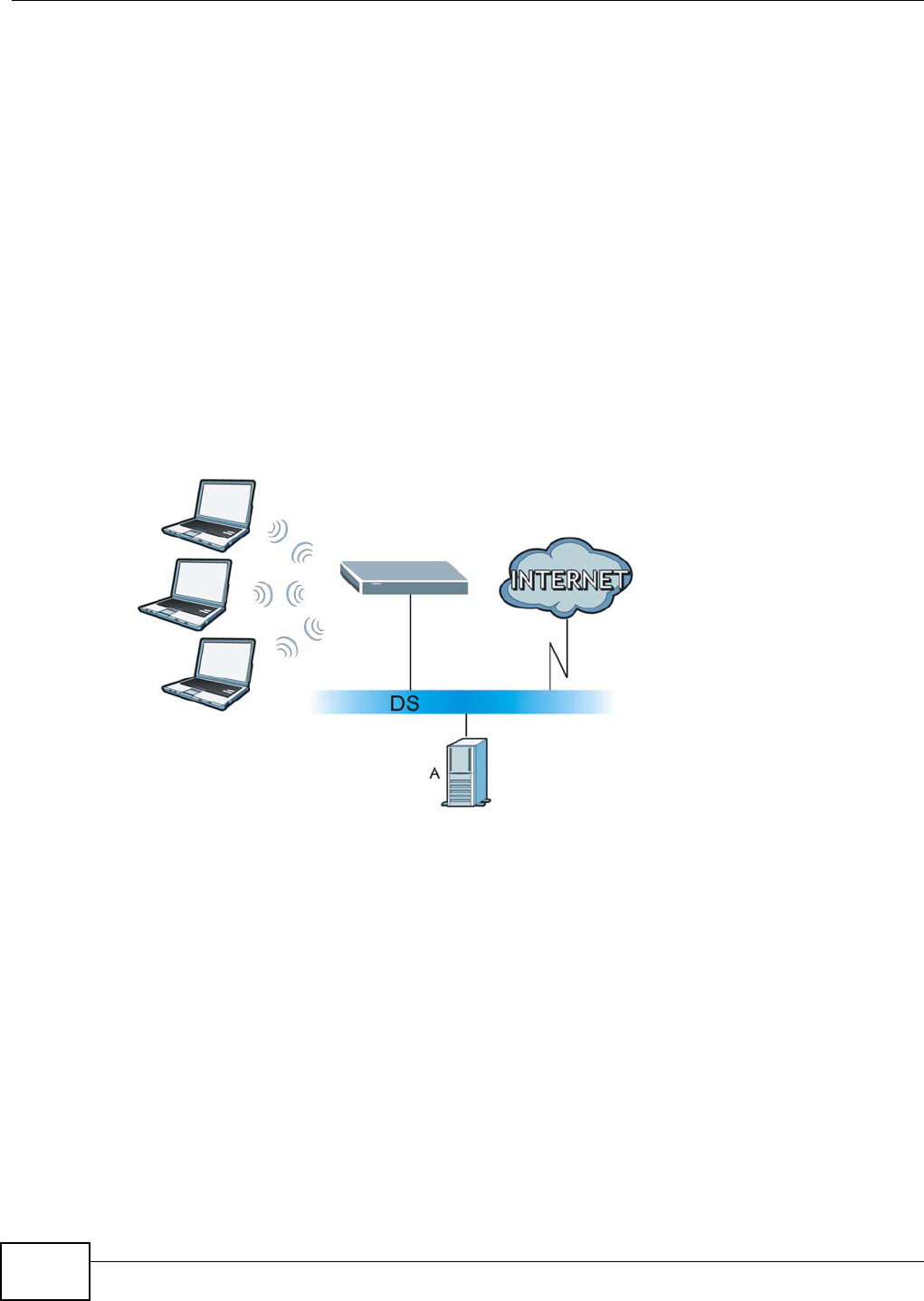
Appendix D Wireless LANs
AMG1312-T Series User’s Guide
274
WPA(2) with RADIUS Application Example
To set up WPA(2), you need the IP address of the RADIUS server, its port number (default is 1812),
and the RADIUS shared secret. A WPA(2) application example with an external RADIUS server
looks as follows. "A" is the RADIUS server. "DS" is the distribution system.
1The AP passes the wireless client's authentication request to the RADIUS server.
2The RADIUS server then checks the user's identification against its database and grants or denies
network access accordingly.
3A 256-bit Pairwise Master Key (PMK) is derived from the authentication process by the RADIUS
server and the client.
4The RADIUS server distributes the PMK to the AP. The AP then sets up a key hierarchy and
management system, using the PMK to dynamically generate unique data encryption keys. The
keys are used to encrypt every data packet that is wirelessly communicated between the AP and
the wireless clients.
Figure 180 WPA(2) with RADIUS Application Example
WPA(2)-PSK Application Example
A WPA(2)-PSK application looks as follows.
1First enter identical passwords into the AP and all wireless clients. The Pre-Shared Key (PSK) must
consist of between 8 and 63 ASCII characters or 64 hexadecimal characters (including spaces and
symbols).
2The AP checks each wireless client's password and allows it to join the network only if the password
matches.
3The AP and wireless clients generate a common PMK (Pairwise Master Key). The key itself is not
sent over the network, but is derived from the PSK and the SSID.
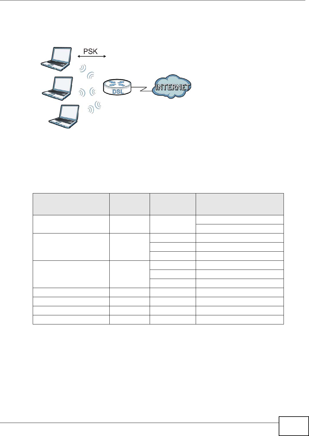
Appendix D Wireless LANs
AMG1312-T Series User’s Guide 275
4The AP and wireless clients use the TKIP or AES encryption process, the PMK and information
exchanged in a handshake to create temporal encryption keys. They use these keys to encrypt data
exchanged between them.
Figure 181 WPA(2)-PSK Authentication
Security Parameters Summary
Refer to this table to see what other security parameters you should configure for each
authentication method or key management protocol type. MAC address filters are not dependent on
how you configure these security features.
Antenna Overview
An antenna couples RF signals onto air. A transmitter within a wireless device sends an RF signal to
the antenna, which propagates the signal through the air. The antenna also operates in reverse by
capturing RF signals from the air.
Positioning the antennas properly increases the range and coverage area of a wireless LAN.
Table 112 Wireless Security Relational Matrix
AUTHENTICATION
METHOD/ KEY
MANAGEMENT PROTOCOL
ENCRYPTIO
N METHOD ENTER
MANUAL KEY IEEE 802.1X
Open None No Disable
Enable without Dynamic WEP Key
Open WEP No Enable with Dynamic WEP Key
Yes Enable without Dynamic WEP Key
Yes Disable
Shared WEP No Enable with Dynamic WEP Key
Yes Enable without Dynamic WEP Key
Yes Disable
WPA TKIP/AES No Enable
WPA-PSK TKIP/AES Yes Disable
WPA2 TKIP/AES No Enable
WPA2-PSK TKIP/AES Yes Disable

Appendix D Wireless LANs
AMG1312-T Series User’s Guide
276
Antenna Characteristics
Frequency
An antenna in the frequency of 2.4GHz (IEEE 802.11b and IEEE 802.11g) or 5GHz (IEEE 802.11a)
is needed to communicate efficiently in a wireless LAN
Radiation Pattern
A radiation pattern is a diagram that allows you to visualize the shape of the antenna’s coverage
area.
Antenna Gain
Antenna gain, measured in dB (decibel), is the increase in coverage within the RF beam width.
Higher antenna gain improves the range of the signal for better communications.
For an indoor site, each 1 dB increase in antenna gain results in a range increase of approximately
2.5%. For an unobstructed outdoor site, each 1dB increase in gain results in a range increase of
approximately 5%. Actual results may vary depending on the network environment.
Antenna gain is sometimes specified in dBi, which is how much the antenna increases the signal
power compared to using an isotropic antenna. An isotropic antenna is a theoretical perfect antenna
that sends out radio signals equally well in all directions. dBi represents the true gain that the
antenna provides.
Types of Antennas for WLAN
There are two types of antennas used for wireless LAN applications.
• Omni-directional antennas send the RF signal out in all directions on a horizontal plane. The
coverage area is torus-shaped (like a donut) which makes these antennas ideal for a room
environment. With a wide coverage area, it is possible to make circular overlapping coverage
areas with multiple access points.
• Directional antennas concentrate the RF signal in a beam, like a flashlight does with the light
from its bulb. The angle of the beam determines the width of the coverage pattern. Angles
typically range from 20 degrees (very directional) to 120 degrees (less directional). Directional
antennas are ideal for hallways and outdoor point-to-point applications.
Positioning Antennas
In general, antennas should be mounted as high as practically possible and free of obstructions. In
point-to–point application, position both antennas at the same height and in a direct line of sight to
each other to attain the best performance.
For omni-directional antennas mounted on a table, desk, and so on, point the antenna up. For
omni-directional antennas mounted on a wall or ceiling, point the antenna down. For a single AP
application, place omni-directional antennas as close to the center of the coverage area as possible.
For directional antennas, point the antenna in the direction of the desired coverage area.

AMG1312-T Series User’s Guide 277
APPENDIX E
IPv6
Overview
IPv6 (Internet Protocol version 6), is designed to enhance IP address size and features. The
increase in IPv6 address size to 128 bits (from the 32-bit IPv4 address) allows up to 3.4 x 1038 IP
addresses.
IPv6 Addressing
The 128-bit IPv6 address is written as eight 16-bit hexadecimal blocks separated by colons (:). This
is an example IPv6 address 2001:0db8:1a2b:0015:0000:0000:1a2f:0000.
IPv6 addresses can be abbreviated in two ways:
• Leading zeros in a block can be omitted. So 2001:0db8:1a2b:0015:0000:0000:1a2f:0000 can
be written as 2001:db8:1a2b:15:0:0:1a2f:0.
• Any number of consecutive blocks of zeros can be replaced by a double colon. A double colon can
only appear once in an IPv6 address. So 2001:0db8:0000:0000:1a2f:0000:0000:0015 can be
written as 2001:0db8::1a2f:0000:0000:0015, 2001:0db8:0000:0000:1a2f::0015,
2001:db8::1a2f:0:0:15 or 2001:db8:0:0:1a2f::15.
Prefix and Prefix Length
Similar to an IPv4 subnet mask, IPv6 uses an address prefix to represent the network address. An
IPv6 prefix length specifies how many most significant bits (start from the left) in the address
compose the network address. The prefix length is written as “/x” where x is a number. For
example,
2001:db8:1a2b:15::1a2f:0/32
means that the first 32 bits (2001:db8) is the subnet prefix.
Link-local Address
A link-local address uniquely identifies a device on the local network (the LAN). It is similar to a
“private IP address” in IPv4. You can have the same link-local address on multiple interfaces on a
device. A link-local unicast address has a predefined prefix of fe80::/10. The link-local unicast
address format is as follows.
Table 113 Link-local Unicast Address Format
1111 1110 10 0 Interface ID
10 bits 54 bits 64 bits
Appendix E IPv6
AMG1312-T Series User’s Guide
278
Global Address
A global address uniquely identifies a device on the Internet. It is similar to a “public IP address” in
IPv4. A global unicast address starts with a 2 or 3.
Unspecified Address
An unspecified address (0:0:0:0:0:0:0:0 or ::) is used as the source address when a device does
not have its own address. It is similar to “0.0.0.0” in IPv4.
Loopback Address
A loopback address (0:0:0:0:0:0:0:1 or ::1) allows a host to send packets to itself. It is similar to
“127.0.0.1” in IPv4.
Multicast Address
In IPv6, multicast addresses provide the same functionality as IPv4 broadcast addresses.
Broadcasting is not supported in IPv6. A multicast address allows a host to send packets to all hosts
in a multicast group.
Multicast scope allows you to determine the size of the multicast group. A multicast address has a
predefined prefix of ff00::/8. The following table describes some of the predefined multicast
addresses.
The following table describes the multicast addresses which are reserved and can not be assigned
to a multicast group.
Table 114 Predefined Multicast Address
MULTICAST ADDRESS DESCRIPTION
FF01:0:0:0:0:0:0:1 All hosts on a local node.
FF01:0:0:0:0:0:0:2 All routers on a local node.
FF02:0:0:0:0:0:0:1 All hosts on a local connected link.
FF02:0:0:0:0:0:0:2 All routers on a local connected link.
FF05:0:0:0:0:0:0:2 All routers on a local site.
FF05:0:0:0:0:0:1:3 All DHCP severs on a local site.
Table 115 Reserved Multicast Address
MULTICAST ADDRESS
FF00:0:0:0:0:0:0:0
FF01:0:0:0:0:0:0:0
FF02:0:0:0:0:0:0:0
FF03:0:0:0:0:0:0:0
FF04:0:0:0:0:0:0:0
FF05:0:0:0:0:0:0:0
FF06:0:0:0:0:0:0:0
FF07:0:0:0:0:0:0:0
Appendix E IPv6
AMG1312-T Series User’s Guide 279
Subnet Masking
Both an IPv6 address and IPv6 subnet mask compose of 128-bit binary digits, which are divided
into eight 16-bit blocks and written in hexadecimal notation. Hexadecimal uses four bits for each
character (1 ~ 10, A ~ F). Each block’s 16 bits are then represented by four hexadecimal
characters. For example, FFFF:FFFF:FFFF:FFFF:FC00:0000:0000:0000.
Interface ID
In IPv6, an interface ID is a 64-bit identifier. It identifies a physical interface (for example, an
Ethernet port) or a virtual interface (for example, the management IP address for a VLAN). One
interface should have a unique interface ID.
EUI-64
The EUI-64 (Extended Unique Identifier) defined by the IEEE (Institute of Electrical and Electronics
Engineers) is an interface ID format designed to adapt with IPv6. It is derived from the 48-bit (6-
byte) Ethernet MAC address as shown next. EUI-64 inserts the hex digits fffe between the third and
fourth bytes of the MAC address and complements the seventh bit of the first byte of the MAC
address. See the following example.
Stateless Autoconfiguration
With stateless autoconfiguration in IPv6, addresses can be uniquely and automatically generated.
Unlike DHCPv6 (Dynamic Host Configuration Protocol version six) which is used in IPv6 stateful
autoconfiguration, the owner and status of addresses don’t need to be maintained by a DHCP
server. Every IPv6 device is able to generate its own and unique IP address automatically when
IPv6 is initiated on its interface. It combines the prefix and the interface ID (generated from its own
Ethernet MAC address, see Interface ID and EUI-64) to form a complete IPv6 address.
When IPv6 is enabled on a device, its interface automatically generates a link-local address
(beginning with fe80).
When the interface is connected to a network with a router and the AMG1312-T Series is set to
automatically obtain an IPv6 network prefix from the router for the interface, it generates 3another
FF08:0:0:0:0:0:0:0
FF09:0:0:0:0:0:0:0
FF0A:0:0:0:0:0:0:0
FF0B:0:0:0:0:0:0:0
FF0C:0:0:0:0:0:0:0
FF0D:0:0:0:0:0:0:0
FF0E:0:0:0:0:0:0:0
FF0F:0:0:0:0:0:0:0
Table 115 Reserved Multicast Address (continued)
MULTICAST ADDRESS
MAC 00 : 13 : 49 :12 : 34 :56
EUI-64 02:13 :49 :FF :FE :12 : 34 :56
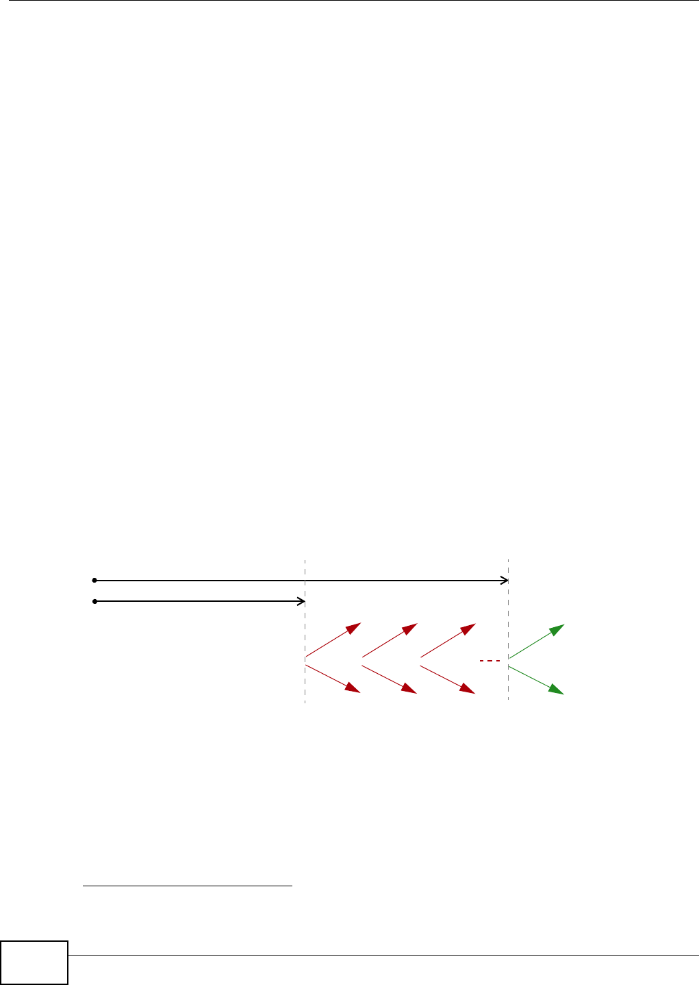
Appendix E IPv6
AMG1312-T Series User’s Guide
280
address which combines its interface ID and global and subnet information advertised from the
router. This is a routable global IP address.
DHCPv6
The Dynamic Host Configuration Protocol for IPv6 (DHCPv6, RFC 3315) is a server-client protocol
that allows a DHCP server to assign and pass IPv6 network addresses, prefixes and other
configuration information to DHCP clients. DHCPv6 servers and clients exchange DHCP messages
using UDP.
Each DHCP client and server has a unique DHCP Unique IDentifier (DUID), which is used for
identification when they are exchanging DHCPv6 messages. The DUID is generated from the MAC
address, time, vendor assigned ID and/or the vendor's private enterprise number registered with
the IANA. It should not change over time even after you reboot the device.
Identity Association
An Identity Association (IA) is a collection of addresses assigned to a DHCP client, through which
the server and client can manage a set of related IP addresses. Each IA must be associated with
exactly one interface. The DHCP client uses the IA assigned to an interface to obtain configuration
from a DHCP server for that interface. Each IA consists of a unique IAID and associated IP
information.
The IA type is the type of address in the IA. Each IA holds one type of address. IA_NA means an
identity association for non-temporary addresses and IA_TA is an identity association for temporary
addresses. An IA_NA option contains the T1 and T2 fields, but an IA_TA option does not. The
DHCPv6 server uses T1 and T2 to control the time at which the client contacts with the server to
extend the lifetimes on any addresses in the IA_NA before the lifetimes expire. After T1, the client
sends the server (S1) (from which the addresses in the IA_NA were obtained) a Renew message. If
the time T2 is reached and the server does not respond, the client sends a Rebind message to any
available server (S2). For an IA_TA, the client may send a Renew or Rebind message at the client's
discretion.
DHCP Relay Agent
A DHCP relay agent is on the same network as the DHCP clients and helps forward messages
between the DHCP server and clients. When a client cannot use its link-local address and a well-
known multicast address to locate a DHCP server on its network, it then needs a DHCP relay agent
to send a message to a DHCP server that is not attached to the same network.
The DHCP relay agent can add the remote identification (remote-ID) option and the interface-ID
option to the Relay-Forward DHCPv6 messages. The remote-ID option carries a user-defined string,
3. In IPv6, all network interfaces can be associated with several addresses.
T1
T2
Renew Rebind
Rebind
to S1
Renew
to S1
Renew
to S1
Renew
to S1
Renew
to S1
Renew
to S1
to S2
to S2

Appendix E IPv6
AMG1312-T Series User’s Guide 281
such as the system name. The interface-ID option provides slot number, port information and the
VLAN ID to the DHCPv6 server. The remote-ID option (if any) is stripped from the Relay-Reply
messages before the relay agent sends the packets to the clients. The DHCP server copies the
interface-ID option from the Relay-Forward message into the Relay-Reply message and sends it to
the relay agent. The interface-ID should not change even after the relay agent restarts.
Prefix Delegation
Prefix delegation enables an IPv6 router to use the IPv6 prefix (network address) received from the
ISP (or a connected uplink router) for its LAN. The AMG1312-T Series uses the received IPv6 prefix
(for example, 2001:db2::/48) to generate its LAN IP address. Through sending Router
Advertisements (RAs) regularly by multicast, the AMG1312-T Series passes the IPv6 prefix
information to its LAN hosts. The hosts then can use the prefix to generate their IPv6 addresses.
ICMPv6
Internet Control Message Protocol for IPv6 (ICMPv6 or ICMP for IPv6) is defined in RFC 4443.
ICMPv6 has a preceding Next Header value of 58, which is different from the value used to identify
ICMP for IPv4. ICMPv6 is an integral part of IPv6. IPv6 nodes use ICMPv6 to report errors
encountered in packet processing and perform other diagnostic functions, such as "ping".
Multicast Listener Discovery
The Multicast Listener Discovery (MLD) protocol (defined in RFC 2710) is derived from IPv4's
Internet Group Management Protocol version 2 (IGMPv2). MLD uses ICMPv6 message types, rather
than IGMP message types. MLDv1 is equivalent to IGMPv2 and MLDv2 is equivalent to IGMPv3.
MLD allows an IPv6 switch or router to discover the presence of MLD listeners who wish to receive
multicast packets and the IP addresses of multicast groups the hosts want to join on its network.
MLD snooping and MLD proxy are analogous to IGMP snooping and IGMP proxy in IPv4.
MLD filtering controls which multicast groups a port can join.
MLD Messages
A multicast router or switch periodically sends general queries to MLD hosts to update the multicast
forwarding table. When an MLD host wants to join a multicast group, it sends an MLD Report
message for that address.
An MLD Done message is equivalent to an IGMP Leave message. When an MLD host wants to leave
a multicast group, it can send a Done message to the router or switch. The router or switch then
sends a group-specific query to the port on which the Done message is received to determine if
other devices connected to this port should remain in the group.
Transition Techniques
IPv6 Over IPv4 Tunnelling
To route traffic between two IPv6 networks over an IPv4 network, an IPv6 over IPv4 tunnel has to
be used.
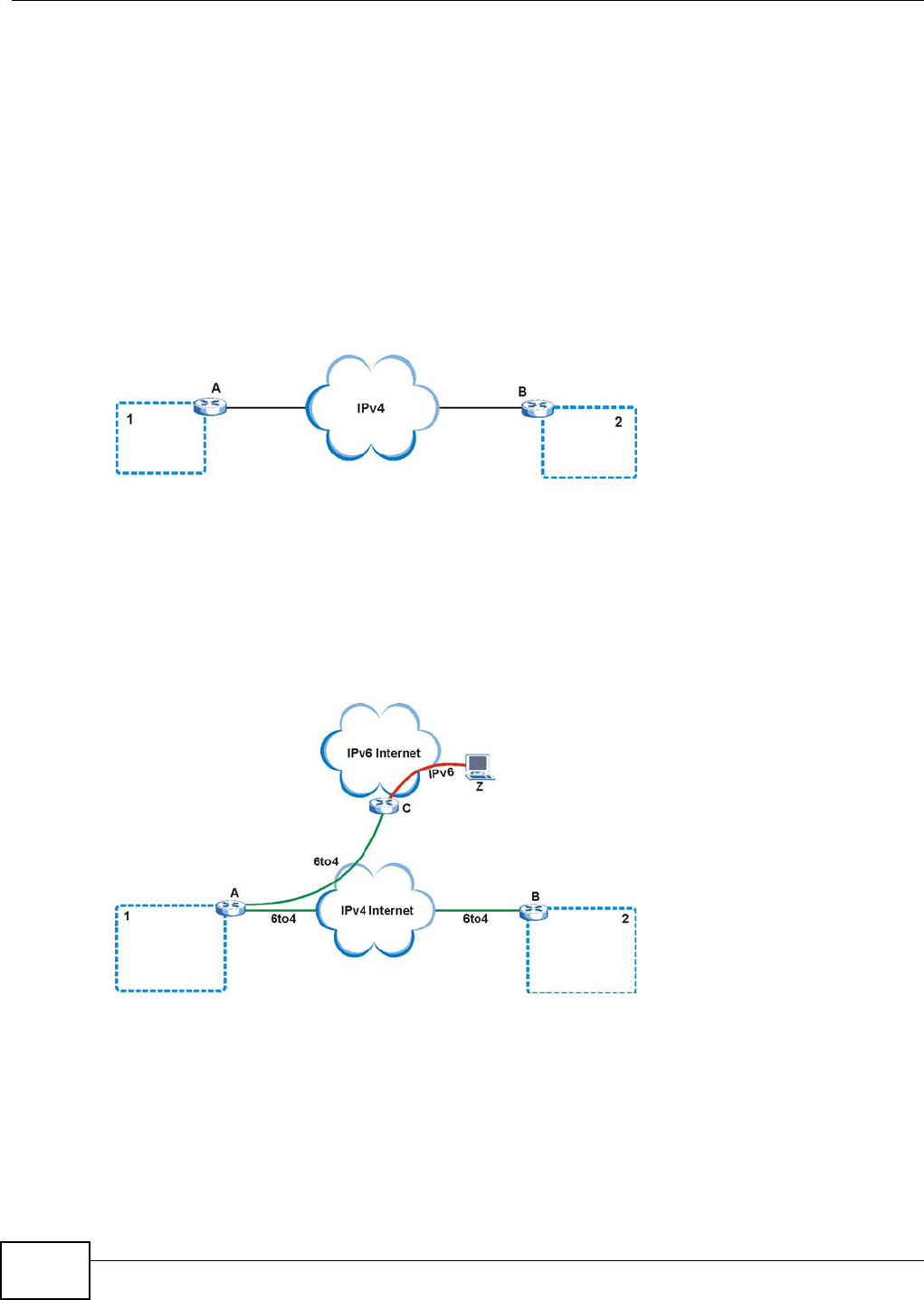
Appendix E IPv6
AMG1312-T Series User’s Guide
282
On the AMG1312-T Series, you can either set up a configured tunnel or an automatic 6to4 tunnel.
The following describes each method.
Configured Tunnel
A configured tunnel is a point-to-point tunnelling mechanism that encapsulates an IPv6 address
with an IPv4 address. Routers (A and B) on both IPv6 networks (1 and 2) each must have an
interface that connects to the IPv4 network (with an IPv4 address). This allows the router to send
and receive IPv6 data over the IPv4 network.
In this case, you must specify B’s public IPv4 address on A (similarly, specify A’s public IPv4
address on B) in order for packets to arrive at the intended destination through the IPv4 network.
Figure 182 Configured Tunnel Example
6to4 Tunnel
A 6to4 tunnel is an automatic tunnelling mechanism that provides connection between IPv6
networks across an IPv4 network. To transmit IPv6 packets over an IPv4 network, the IPv6 packets
are encapsulated inside IPv4 packets.
The following figure shows a network example.
Figure 183 6to4 Relay Router Network Example
In a 6to4 tunnel, 6to4 routers (A and B in the example network) forward these packets between
IPv6 networks (1 and 2) over the IPv4 Internet. A 6to4 relay router (C) connects to both an IPv6
and IPv4 network. A 6to4 relay router is used to forward packets between 6to4 routers in an IPv4
Internet and an IPv6 device (Z) on the IPv6 Internet.
To transmit packets, a 6to4 address is used with a special IPv6 prefix of 2002:: to encode a given
IPv4 address. A 6to4 address has the following format:
2002:IPv4 address:subnet ID:host ID/64

Appendix E IPv6
AMG1312-T Series User’s Guide 283
For example, if you have an IPv4 address of 192.168.1.1 (first converted to binary notation and then to
the colon hexadecimal representation of c0a8:0101), then the 6to4 addresses is 2002:c0a8:0101::1/
64.
Example - Enabling IPv6 on Windows XP/2003/Vista
By default, Windows XP and Windows 2003 support IPv6. This example shows you how to use the
ipv6 install command on Windows XP/2003 to enable IPv6. This also displays how to use the
ipconfig command to see auto-generated IP addresses.
IPv6 is installed and enabled by default in Windows Vista. Use the ipconfig command to check
your automatic configured IPv6 address as well. You should see at least one IPv6 address available
for the interface on your computer.
Example - Enabling DHCPv6 on Windows XP
Windows XP does not support DHCPv6. If your network uses DHCPv6 for IP address assignment,
you have to additionally install a DHCPv6 client software on your Windows XP. (Note: If you use
static IP addresses or Router Advertisement for IPv6 address assignment in your network, ignore
this section.)
This example uses Dibbler as the DHCPv6 client. To enable DHCPv6 client on your computer:
1Install Dibbler and select the DHCPv6 client option on your computer.
2After the installation is complete, select Start > All Programs > Dibbler-DHCPv6 > Client
Install as service.
3Select Start > Control Panel > Administrative Tools > Services.
4Double click Dibbler - a DHCPv6 client.
C:\>ipv6 install
Installing...
Succeeded.
C:\>ipconfig
Windows IP Configuration
Ethernet adapter Local Area Connection:
Connection-specific DNS Suffix . :
IP Address. . . . . . . . . . . . : 10.1.1.46
Subnet Mask . . . . . . . . . . . : 255.255.255.0
IP Address. . . . . . . . . . . . : fe80::2d0:59ff:feb8:103c%4
Default Gateway . . . . . . . . . : 10.1.1.254
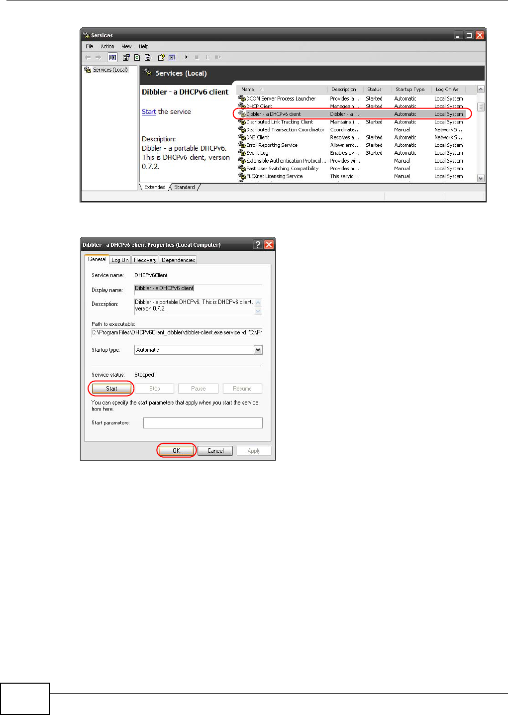
Appendix E IPv6
AMG1312-T Series User’s Guide
284
5Click Start and then OK.
6Now your computer can obtain an IPv6 address from a DHCPv6 server.
Example - Enabling IPv6 on Windows 7
Windows 7 supports IPv6 by default. DHCPv6 is also enabled when you enable IPv6 on a Windows 7
computer.
To enable IPv6 in Windows 7:
1Select Control Panel > Network and Sharing Center > Local Area Connection.
2Select the Internet Protocol Version 6 (TCP/IPv6) checkbox to enable it.
3Click OK to save the change.
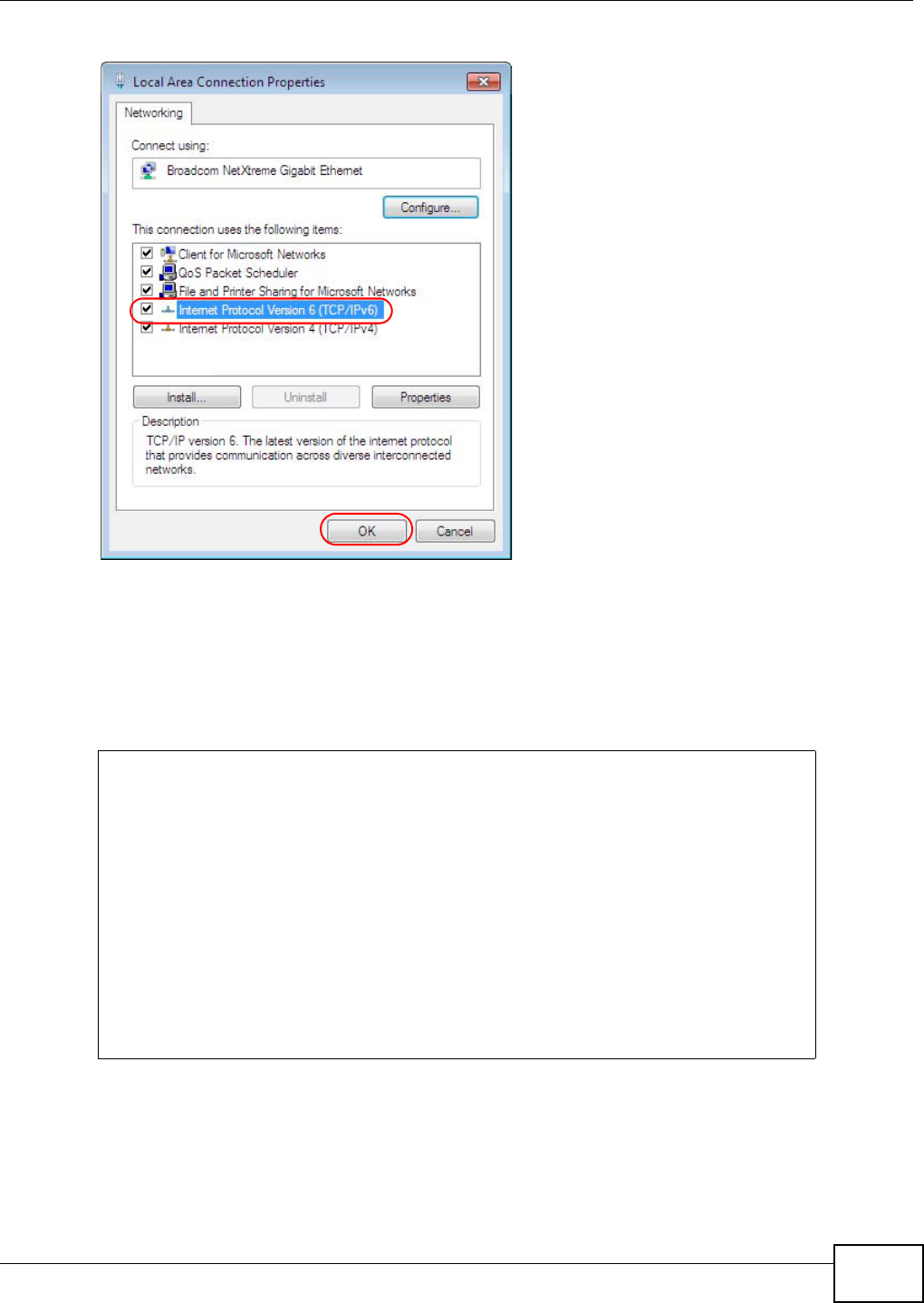
Appendix E IPv6
AMG1312-T Series User’s Guide 285
4Click Close to exit the Local Area Connection Status screen.
5Select Start > All Programs > Accessories > Command Prompt.
6Use the ipconfig command to check your dynamic IPv6 address. This example shows a global
address (2001:b021:2d::1000) obtained from a DHCP server.
C:\>ipconfig
Windows IP Configuration
Ethernet adapter Local Area Connection:
Connection-specific DNS Suffix . :
IPv6 Address. . . . . . . . . . . : 2001:b021:2d::1000
Link-local IPv6 Address . . . . . : fe80::25d8:dcab:c80a:5189%11
IPv4 Address. . . . . . . . . . . : 172.16.100.61
Subnet Mask . . . . . . . . . . . : 255.255.255.0
Default Gateway . . . . . . . . . : fe80::213:49ff:feaa:7125%11
172.16.100.254

AMG1312-T Series User’s Guide 286
APPENDIX F
Services
The following table lists some commonly-used services and their associated protocols and port
numbers.
•Name: This is a short, descriptive name for the service. You can use this one or create a
different one, if you like.
•Protocol: This is the type of IP protocol used by the service. If this is TCP/UDP, then the service
uses the same port number with TCP and UDP. If this is USER-DEFINED, the Port(s) is the IP
protocol number, not the port number.
•Port(s): This value depends on the Protocol.
•If the Protocol is TCP, UDP, or TCP/UDP, this is the IP port number.
•If the Protocol is USER, this is the IP protocol number.
•Description: This is a brief explanation of the applications that use this service or the situations
in which this service is used.

Appendix F Services
AMG1312-T Series User’s Guide 287
Table 116 Examples of Services
NAME PROTOCOL PORT(S) DESCRIPTION
AH (IPSEC_TUNNEL) User-Defined 51 The IPSEC AH (Authentication Header)
tunneling protocol uses this service.
AIM TCP 5190 AOL’s Internet Messenger service.
AUTH TCP 113 Authentication protocol used by some
servers.
BGP TCP 179 Border Gateway Protocol.
BOOTP_CLIENT UDP 68 DHCP Client.
BOOTP_SERVER UDP 67 DHCP Server.
CU-SEEME TCP/UDP
TCP/UDP
7648
24032
A popular videoconferencing solution from
White Pines Software.
DNS TCP/UDP 53 Domain Name Server, a service that
matches web names (for instance
www.zyxel.com) to IP numbers.
ESP
(IPSEC_TUNNEL)
User-Defined 50 The IPSEC ESP (Encapsulation Security
Protocol) tunneling protocol uses this
service.
FINGER TCP 79 Finger is a UNIX or Internet related
command that can be used to find out if a
user is logged on.
FTP TCP
TCP
20
21
File Transfer Protocol, a program to enable
fast transfer of files, including large files
that may not be possible by e-mail.
H.323 TCP 1720 NetMeeting uses this protocol.
HTTP TCP 80 Hyper Text Transfer Protocol - a client/
server protocol for the world wide web.
HTTPS TCP 443 HTTPS is a secured http session often used
in e-commerce.
ICMP User-Defined 1Internet Control Message Protocol is often
used for diagnostic purposes.
ICQ UDP 4000 This is a popular Internet chat program.
IGMP (MULTICAST) User-Defined 2Internet Group Multicast Protocol is used
when sending packets to a specific group
of hosts.
IKE UDP 500 The Internet Key Exchange algorithm is
used for key distribution and management.
IMAP4 TCP 143 The Internet Message Access Protocol is
used for e-mail.
IMAP4S TCP 993 This is a more secure version of IMAP4 that
runs over SSL.
IRC TCP/UDP 6667 This is another popular Internet chat
program.
MSN Messenger TCP 1863 Microsoft Networks’ messenger service
uses this protocol.
NetBIOS TCP/UDP
TCP/UDP
TCP/UDP
TCP/UDP
137
138
139
445
The Network Basic Input/Output System is
used for communication between
computers in a LAN.

Appendix F Services
AMG1312-T Series User’s Guide
288
NEW-ICQ TCP 5190 An Internet chat program.
NEWS TCP 144 A protocol for news groups.
NFS UDP 2049 Network File System - NFS is a client/
server distributed file service that provides
transparent file sharing for network
environments.
NNTP TCP 119 Network News Transport Protocol is the
delivery mechanism for the USENET
newsgroup service.
PING User-Defined 1Packet INternet Groper is a protocol that
sends out ICMP echo requests to test
whether or not a remote host is reachable.
POP3 TCP 110 Post Office Protocol version 3 lets a client
computer get e-mail from a POP3 server
through a temporary connection (TCP/IP or
other).
POP3S TCP 995 This is a more secure version of POP3 that
runs over SSL.
PPTP TCP 1723 Point-to-Point Tunneling Protocol enables
secure transfer of data over public
networks. This is the control channel.
PPTP_TUNNEL (GRE) User-Defined 47 PPTP (Point-to-Point Tunneling Protocol)
enables secure transfer of data over public
networks. This is the data channel.
RCMD TCP 512 Remote Command Service.
REAL_AUDIO TCP 7070 A streaming audio service that enables real
time sound over the web.
REXEC TCP 514 Remote Execution Daemon.
RLOGIN TCP 513 Remote Login.
ROADRUNNER TCP/UDP 1026 This is an ISP that provides services mainly
for cable modems.
RTELNET TCP 107 Remote Telnet.
RTSP TCP/UDP 554 The Real Time Streaming (media control)
Protocol (RTSP) is a remote control for
multimedia on the Internet.
SFTP TCP 115 The Simple File Transfer Protocol is an old
way of transferring files between
computers.
SMTP TCP 25 Simple Mail Transfer Protocol is the
message-exchange standard for the
Internet. SMTP enables you to move
messages from one e-mail server to
another.
SMTPS TCP 465 This is a more secure version of SMTP that
runs over SSL.
SNMP TCP/UDP 161 Simple Network Management Program.
SNMP-TRAPS TCP/UDP 162 Traps for use with the SNMP (RFC:1215).
Table 116 Examples of Services (continued)
NAME PROTOCOL PORT(S) DESCRIPTION

Appendix F Services
AMG1312-T Series User’s Guide 289
SQL-NET TCP 1521 Structured Query Language is an interface
to access data on many different types of
database systems, including mainframes,
midrange systems, UNIX systems and
network servers.
SSDP UDP 1900 The Simple Service Discovery Protocol
supports Universal Plug-and-Play (UPnP).
SSH TCP/UDP 22 Secure Shell Remote Login Program.
STRM WORKS UDP 1558 Stream Works Protocol.
SYSLOG UDP 514 Syslog allows you to send system logs to a
UNIX server.
TACACS UDP 49 Login Host Protocol used for (Terminal
Access Controller Access Control System).
TELNET TCP 23 Telnet is the login and terminal emulation
protocol common on the Internet and in
UNIX environments. It operates over TCP/
IP networks. Its primary function is to
allow users to log into remote host
systems.
VDOLIVE TCP
UDP
7000
user-
defined
A videoconferencing solution. The UDP port
number is specified in the application.
Table 116 Examples of Services (continued)
NAME PROTOCOL PORT(S) DESCRIPTION
AMG1312-T Series User’s Guide 290
APPENDIX G
Legal Information
Copyright
Copyright © 2013 by ZyXEL Communications Corporation.
The contents of this publication may not be reproduced in any part or as a whole, transcribed, stored in a retrieval system, translated into
any language, or transmitted in any form or by any means, electronic, mechanical, magnetic, optical, chemical, photocopying, manual, or
otherwise, without the prior written permission of ZyXEL Communications Corporation.
Published by ZyXEL Communications Corporation. All rights reserved.
Disclaimer
ZyXEL does not assume any liability arising out of the application or use of any products, or software described herein. Neither does it
convey any license under its patent rights nor the patent rights of others. ZyXEL further reserves the right to make changes in any
products described herein without notice. This publication is subject to change without notice.
Trademarks
ZyNOS (ZyXEL Network Operating System) is a registered trademark of ZyXEL Communications, Inc. Other trademarks mentioned in this
publication are used for identification purposes only and may be properties of their respective owners.
Certifications
Federal Communications Commission (FCC) Interference Statement
The device complies with Part 15 of FCC rules. Operation is subject to the following two conditions:
• This device may not cause harmful interference.
• This device must accept any interference received, including interference that may cause undesired operations.
This device has been tested and found to comply with the limits for a Class B digital device pursuant to Part 15 of the FCC Rules. These
limits are designed to provide reasonable protection against harmful interference in a residential installation. This device generates, uses,
and can radiate radio frequency energy, and if not installed and used in accordance with the instructions, may cause harmful interference
to radio communications. However, there is no guarantee that interference will not occur in a particular installation.
If this device does cause harmful interference to radio/television reception, which can be determined by turning the device off and on, the
user is encouraged to try to correct the interference by one or more of the following measures:
1Reorient or relocate the receiving antenna.
2Increase the separation between the equipment and the receiver.
3Connect the equipment into an outlet on a circuit different from that to which the receiver is connected.
4Consult the dealer or an experienced radio/TV technician for help.
FCC Radiation Exposure Statement
• This transmitter must not be co-located or operating in conjunction with any other antenna or transmitter.
• IEEE 802.11b, 802.11g or 802.11n(20MHz) operation of this product in the U.S.A. is firmware-limited to channels 1 through 11. IEEE
802.11n(40MHz) operation of this product in the U.S.A. is firmware-limited to channels 1 through 7.
• To comply with FCC RF exposure compliance requirements, a separation distance of at least 20 cm must be maintained between the
antenna of this device and all persons.
Note: only channels 1 to 11 (frequency band 2.412 GHz to 2.462 GHz) are available for use in the United States of America.
注意 !
依據 低功率電波輻射性電機管理辦法
第十二條 經型式認證合格之低功率射頻電機,非經許可,公司、商號或使用
者均不得擅自變更頻率、加大功率或變更原設計之特性及功能。
第十四條 低功率射頻電機之使用不得影響飛航安全及干擾合法通信;經發現
有干擾現象時,應立即停用,並改善至無干擾時方得繼續使用。
前項合法通信,指依電信規定作業之無線電信。低功率射頻電機須忍
受合法通信或工業、科學及醫療用電波輻射性電機設備之干擾。
本機限在不干擾合法電臺與不受被干擾保障條件下於室內使用。
減少電磁波影響,請妥適使用。

Appendix G Legal Information
AMG1312-T Series User’s Guide 291
Notices
Changes or modifications not expressly approved by the party responsible for compliance could void the user's authority to operate the
equipment.
This Class B digital apparatus complies with Canadian ICES-003.
Cet appareil numérique de la classe B est conforme à la norme NMB-003 du Canada.
Viewing Certifications
Go to www.zyxel.com to view the product’s documents and certifications.
ZyXEL Limited Warranty
ZyXEL warrants to the original end user (purchaser) that this product is free from any defects in materials or workmanship for a period of
up to two years from the date of purchase. During the warranty period, and upon proof of purchase, should the product have indications
of failure due to faulty workmanship and/or materials, ZyXEL will, at its discretion, repair or replace the defective products or components
without charge for either parts or labor, and to whatever extent it shall deem necessary to restore the product or components to proper
operating condition. Any replacement will consist of a new or re-manufactured functionally equivalent product of equal or higher value,
and will be solely at the discretion of ZyXEL. This warranty shall not apply if the product has been modified, misused, tampered with,
damaged by an act of God, or subjected to abnormal working conditions.
Note
Repair or replacement, as provided under this warranty, is the exclusive remedy of the purchaser. This warranty is in lieu of all other
warranties, express or implied, including any implied warranty of merchantability or fitness for a particular use or purpose. ZyXEL shall in
no event be held liable for indirect or consequential damages of any kind to the purchaser.
To obtain the services of this warranty, contact ZyXEL's Service Center for your Return Material Authorization number (RMA). Products
must be returned Postage Prepaid. It is recommended that the unit be insured when shipped. Any returned products without proof of
purchase or those with an out-dated warranty will be repaired or replaced (at the discretion of ZyXEL) and the customer will be billed for
parts and labor. All repaired or replaced products will be shipped by ZyXEL to the corresponding return address, Postage Paid. This
warranty gives you specific legal rights, and you may also have other rights that vary from country to country.
Registration
Register your product online to receive e-mail notices of firmware upgrades and information at www.zyxel.com for global products, or at
www.us.zyxel.com for North American products.
Regulatory Information
European Union
The following information applies if you use the product within the European Union.
Declaration of Conformity with Regard to EU Directive 1999/5/EC (R&TTE Directive)
Compliance Information for 2.4GHz and 5GHz Wireless Products Relevant to the EU and Other Countries Following the EU Directive 1999/5/EC
(R&TTE Directive)
[Czech] ZyXEL tímto prohlašuje, že tento zařízení je ve shodě se základními požadavky a dalšími příslušnými
ustanoveními směrnice 1999/5/EC.
[Danish] Undertegnede ZyXEL erklærer herved, at følgende udstyr udstyr overholder de væsentlige krav og øvrige
relevante krav i direktiv 1999/5/EF.
[German] Hiermit erklärt ZyXEL, dass sich das Gerät Ausstattung in Übereinstimmung mit den grundlegenden
Anforderungen und den übrigen einschlägigen Bestimmungen der Richtlinie 1999/5/EU befindet.
[Estonian] Käesolevaga kinnitab ZyXEL seadme seadmed vastavust direktiivi 1999/5/EÜ põhinõuetele ja nimetatud
direktiivist tulenevatele teistele asjakohastele sätetele.
English Hereby, ZyXEL declares that this equipment is in compliance with the essential requirements and other
relevant provisions of Directive 1999/5/EC.
[Spanish] Por medio de la presente ZyXEL declara que el equipo cumple con los requisitos esenciales y cualesquiera
otras disposiciones aplicables o exigibles de la Directiva 1999/5/CE.
[Greek] ΜΕ ΤΗΝ ΠΑΡΟΥΣΑ ZyXEL ∆ΗΛΩΝΕΙ ΟΤΙ εξοπλισμός ΣΥΜΜΟΡΦΩΝΕΤΑΙ ΠΡΟΣ ΤΙΣ ΟΥΣΙΩ∆ΕΙΣ ΑΠΑΙΤΗΣΕΙΣ ΚΑΙ
ΤΙΣ ΛΟΙΠΕΣ ΣΧΕΤΙΚΕΣ ∆ΙΑΤΑΞΕΙΣ ΤΗΣ Ο∆ΗΓΙΑΣ 1999/5/ΕC.
[French] Par la présente ZyXEL déclare que l'appareil équipements est conforme aux exigences essentielles et aux
autres dispositions pertinentes de la directive 1999/5/EC.
[Italian] Con la presente ZyXEL dichiara che questo attrezzatura è conforme ai requisiti essenziali ed alle altre
disposizioni pertinenti stabilite dalla direttiva 1999/5/CE.
[Latvian] Ar šo ZyXEL deklarē, ka iekārtas atbilst Direktīvas 1999/5/EK būtiskajām prasībām un citiem ar to saistītajiem
noteikumiem.
[Lithuanian] Šiuo ZyXEL deklaruoja, kad šis įranga atitinka esminius reikalavimus ir kitas 1999/5/EB Direktyvos nuostatas.
[Dutch] Hierbij verklaart ZyXEL dat het toestel uitrusting in overeenstemming is met de essentiële eisen en de andere
relevante bepalingen van richtlijn 1999/5/EC.
[Maltese] Hawnhekk, ZyXEL, jiddikjara li dan tagħmir jikkonforma mal-ħtiġijiet essenzjali u ma provvedimenti oħrajn
relevanti li hemm fid-Dirrettiva 1999/5/EC.
Appendix G Legal Information
AMG1312-T Series User’s Guide
292
National Restrictions
This product may be used in all EU countries (and other countries following the EU directive 1999/5/EC) without any limitation except for
the countries mentioned below:
Ce produit peut être utilisé dans tous les pays de l’UE (et dans tous les pays ayant transposés la directive 1999/5/CE) sans aucune
limitation, excepté pour les pays mentionnés ci-dessous:
Questo prodotto è utilizzabile in tutte i paesi EU (ed in tutti gli altri paesi che seguono le direttive EU 1999/5/EC) senza nessuna
limitazione, eccetto per i paesii menzionati di seguito:
Das Produkt kann in allen EU Staaten ohne Einschränkungen eingesetzt werden (sowie in anderen Staaten die der EU Direktive 1995/5/CE
folgen) mit Außnahme der folgenden aufgeführten Staaten:
In the majority of the EU and other European countries,the 2,4- and 5-GHz bands have been made available for the use of wireless local
area networks (LANs). Later in this document you will find an overview of countries inwhich additional restrictions or requirements or both
are applicable.
The requirements for any country may evolve. ZyXEL recommends that you check with the local authorities for the latest status of their
national regulations for both the 2,4- and 5-GHz wireless LANs.
The following countries have restrictions and/or requirements in addition to those given in the table labeled “Overview of Regulatory
Requirements for Wireless LANs”:.
Belgium
The Belgian Institute for Postal Services and Telecommunications (BIPT) must be notified of any outdoor wireless link having a range
exceeding 300 meters. Please check http://www.bipt.be for more details.
Draadloze verbindingen voor buitengebruik en met een reikwijdte van meer dan 300 meter dienen aangemeld te worden bij het Belgisch
Instituut voor postdiensten en telecommunicatie (BIPT). Zie http://www.bipt.be voor meer gegevens.
Les liaisons sans fil pour une utilisation en extérieur d’une distance supérieure à 300 mètres doivent être notifiées à l’Institut Belge des
services Postaux et des Télécommunications (IBPT). Visitez http://www.ibpt.be pour de plus amples détails.
Denmark
In Denmark, the band 5150 - 5350 MHz is also allowed for outdoor usage.
I Danmark må frekvensbåndet 5150 - 5350 også anvendes udendørs.
Italy
[Hungarian] Alulírott, ZyXEL nyilatkozom, hogy a berendezés megfelel a vonatkozó alapvetõ követelményeknek és az
1999/5/EK irányelv egyéb elõírásainak.
[Polish] Niniejszym ZyXEL oświadcza, że sprzęt jest zgodny z zasadniczymi wymogami oraz pozostałymi stosownymi
postanowieniami Dyrektywy 1999/5/EC.
[Portuguese] ZyXEL declara que este equipamento está conforme com os requisitos essenciais e outras disposições da
Directiva 1999/5/EC.
[Slovenian] ZyXEL izjavlja, da je ta oprema v skladu z bistvenimi zahtevami in ostalimi relevantnimi določili direktive
1999/5/EC.
[Slovak] ZyXEL týmto vyhlasuje, že zariadenia spĺňa základné požiadavky a všetky príslušné ustanovenia Smernice
1999/5/EC.
[Finnish] ZyXEL vakuuttaa täten että laitteet tyyppinen laite on direktiivin 1999/5/EY oleellisten vaatimusten ja sitä
koskevien direktiivin muiden ehtojen mukainen.
[Swedish] Härmed intygar ZyXEL att denna utrustning står I överensstämmelse med de väsentliga egenskapskrav och
övriga relevanta bestämmelser som framgår av direktiv 1999/5/EC.
[Bulgarian] С настоящото ZyXEL декларира, че това оборудване е в съответствие със съществените изисквания и
другите приложими разпоредбите на Директива 1999/5/ЕC.
[Icelandic] Hér með lýsir, ZyXEL því yfir að þessi búnaður er í samræmi við grunnkröfur og önnur viðeigandi ákvæði
tilskipunar 1999/5/EC.
[Norwegian] Erklærer herved ZyXEL at dette utstyret er I samsvar med de grunnleggende kravene og andre relevante
bestemmelser I direktiv 1999/5/EF.
[Romanian] Prin prezenta, ZyXEL declară că acest echipament este în conformitate cu cerinţele esenţiale şi alte prevederi
relevante ale Directivei 1999/5/EC.
Overview of Regulatory Requirements for Wireless LANs
Frequency Band (MHz) Max Power Level
(EIRP)1 (mW) Indoor ONLY Indoor and Outdoor
2400-2483.5 100 V
5150-5350 200 V
5470-5725 1000 V
Appendix G Legal Information
AMG1312-T Series User’s Guide 293
This product meets the National Radio Interface and the requirements specified in the National Frequency Allocation Table for Italy. Unless
this wireless LAN product is operating within the boundaries of the owner's property, its use requires a “general authorization.” Please
check http://www.sviluppoeconomico.gov.it/ for more details.
Questo prodotto è conforme alla specifiche di Interfaccia Radio Nazionali e rispetta il Piano Nazionale di ripartizione delle frequenze in
Italia. Se non viene installato all 'interno del proprio fondo, l'utilizzo di prodotti Wireless LAN richiede una “Autorizzazione Generale”.
Consultare http://www.sviluppoeconomico.gov.it/ per maggiori dettagli.
Latvia
The outdoor usage of the 2.4 GHz band requires an authorization from the Electronic Communications Office. Please check http://
www.esd.lv for more details.
2.4 GHz frekvenèu joslas izmantoðanai ârpus telpâm nepiecieðama atïauja no Elektronisko sakaru direkcijas. Vairâk informâcijas: http://www.esd.lv.
Notes:
1. Although Norway, Switzerland and Liechtenstein are not EU member states, the EU Directive 1999/5/EC has also been implemented in
those countries.
2. The regulatory limits for maximum output power are specified in EIRP. The EIRP level (in dBm) of a device can be calculated by adding
the gain of the antenna used(specified in dBi) to the output power available at the connector (specified in dBm).
Safety Warnings
• Do NOT use this product near water, for example, in a wet basement or near a swimming pool.
• Do NOT expose your device to dampness, dust or corrosive liquids.
• Do NOT store things on the device.
• Do NOT install, use, or service this device during a thunderstorm. There is a remote risk of electric shock from lightning.
• Connect ONLY suitable accessories to the device.
• Do NOT open the device or unit. Opening or removing covers can expose you to dangerous high voltage points or other risks. ONLY
qualified service personnel should service or disassemble this device. Please contact your vendor for further information.
• Make sure to connect the cables to the correct ports.
• Place connecting cables carefully so that no one will step on them or stumble over them.
• Always disconnect all cables from this device before servicing or disassembling.
• Use ONLY an appropriate power adaptor or cord for your device.
• Connect the power adaptor or cord to the right supply voltage (for example, 110V AC in North America or 230V AC in Europe).
• Do NOT allow anything to rest on the power adaptor or cord and do NOT place the product where anyone can walk on the power
adaptor or cord.
• Do NOT use the device if the power adaptor or cord is damaged as it might cause electrocution.
• If the power adaptor or cord is damaged, remove it from the device and the power source.
• Do NOT attempt to repair the power adaptor or cord. Contact your local vendor to order a new one.
• Do not use the device outside, and make sure all the connections are indoors. There is a remote risk of electric shock from lightning.
• Do NOT obstruct the device ventilation slots, as insufficient airflow may harm your device.
• Use only No. 26 AWG (American Wire Gauge) or larger telecommunication line cord.
• Antenna Warning! This device meets ETSI and FCC certification requirements when using the included antenna(s). Only use the
included antenna(s).
Your product is marked with this symbol, which is known as the WEEE mark. WEEE stands for Waste Electronics and Electrical
Equipment. It means that used electrical and electronic products should not be mixed with general waste. Used electrical and
electronic equipment should be treated separately.

Index
AMG1312-T Series User’s Guide 294
Index
Numbers
802.1p 145
A
activation
CWMP 201
dynamic DNS 162
DYNDNS wildcard 162
NAT 148
port binding 158
port forwarding 151
QoS 138
SSID 94
wireless LAN
scheduling 101
WPS 97
address mapping
types 155
administrator password 19
alternative subnet mask notation 251
antenna
directional 276
gain 276
omni-directional 276
anti-probing 170
AP (access point) 266
applications, NAT 154
Asynchronous Transfer Mode, see ATM
ATM 222
MBS 75, 79
PCR 74, 79
QoS 74, 79, 86
SCR 75, 79
status 222
authentication 104, 105
RADIUS server 105
automatic logout 20
B
backup
configuration 207
Basic Service Set, See BSS 264
Basic Service Set, see BSS
broadcast 69
BSS 107, 264
example 107
C
CA 189, 271
CBR 74, 79, 86
certificate
factory default 190
Certificate Authority
See CA.
certificates 189
authentication 189
CA
public key 189
replacing 190
storage space 190
trusted CAs 191
Certification Authority 189
Certification Authority. see CA
certifications 290
notices 291
viewing 291
channel 266
interference 266
channel, wireless LAN 103
CLI 14
client list 119
Command Line Interface, see CLI
compatibility, WDS 99
configuration
backup 207

Index
AMG1312-T Series User’s Guide295
CWMP 200
DHCP 119
IP alias 121
IP precedence 143
IP/MAC filter 164
port forwarding 149
reset 208
restoring 208
static route 133, 135
WAN 69
wizard 28
connection
nailed-up 84
copyright 290
CPE WAN Management Protocol, see CWMP
CTS (Clear to Send) 267
customized services 176, 178
CWMP 200
activation 201
configuration 200
D
data fragment threshold 101, 104
DDoS 169
default LAN IP address 19
default server address 152
default server, NAT 149
Denials of Service, see DoS
DHCP 66, 116, 119, 128
diagnostic 221
DiffServ Code Point, see DSCP
digital IDs 189
disclaimer 290
DMZ 152
DNS 116, 128, 217
documentation
related 2
Domain Name System, see DNS
DoS 169
three-way handshake 179
thresholds 170, 179, 180
DSCP 143
DSL connections, status 223
dynamic DNS 161
activation 162
wildcard 161
activation 162
Dynamic Host Configuration Protocol, see DHCP
dynamic WEP key exchange 271
DYNDNS wildcard 161
activation 162
E
EAP Authentication 270
encapsulation 68, 71, 78
ENET ENCAP 83
PPPoA 83
PPPoE 83
RFC 1483 83
encryption 106, 272
ENET ENCAP 71, 78, 83
ESS 265
Extended Service Set IDentification 89, 95
Extended Service Set, See ESS 265
F
FCC interference statement 290
filters 163
IP/MAC 163
structure 163
IP/MAC filter
configuration 164
MAC address 96, 105
URL 163
firewalls 168
actions 175
address types 176
anti-probing 170
customized services 176, 178
DDoS 169
default action 172
DoS 169
thresholds 170, 179, 180
ICMP 170
LAND attack 169

Index
AMG1312-T Series User’s Guide 296
logs 175
P2P 180
packet direction 172
Ping of Death 169
rules 181
security 182
SYN attack 169
three-way handshake 179
triangle route 183
solutions 184
firmware 205
forwarding ports 148, 149
activation 151
configuration 149
example 149
rules 150
fragmentation threshold 101, 104, 267
FTP 14, 213
G
Guide
Quick Start 2
H
hidden node 266
host 199
host name 65
I
IANA 256
Internet Assigned Numbers Authority
see IANA
IBSS 264
ICMP 170, 217
IEEE 802.11g 268
IGA 153
IGMP 69, 118, 130
ILA 153
importing trusted CAs 191
Independent Basic Service Set
See IBSS 264
initialization vector (IV) 273
Inside Global Address, see IGA
Inside Local Address, see ILA
Internet Control Message Protocol, see ICMP
Internet Protocol version 6, see IPv6
IP address 65, 69, 72, 78, 84, 116, 129
default 19
default server 149
ping 221
private 129
IP alias 120
configuration 121
NAT applications 155
IP precedence 143, 145
configuration 143
IP/MAC filter 163
configuration 164
structure 163
IPv6 277
addressing 277
EUI-64 279
global address 278
interface ID 279
link-local address 277
Neighbor Discovery Protocol 277
ping 277
prefix 277
prefix length 277
stateless autoconfiguration 279
unspecified address 278
L
LAN 115
client list 119
DHCP 116, 119, 128
DNS 116, 128
IGMP 130
IP address 116, 117, 129
IP alias 120
configuration 121
MAC address 120
multicast 118, 130
RIP 130

Index
AMG1312-T Series User’s Guide297
subnet mask 116, 129
LAND attack 169
limitations
wireless LAN 106
WPS 113
Local Area Network, see LAN
login
passwords 19
logout 20
automatic 20
logs 194
firewalls 175
M
MAC 65
MAC address 96, 120
filter 96, 105
MAC authentication 96
Management Information Base (MIB) 215
managing the device
using FTP. See FTP.
mapping address
types 155
Maximum Burst Size, see MBS
Maximum Transmission Unit, see MTU
MBS 75, 79, 85
MBSSID 107
Media Access Control, see MAC Address
MLD proxy 74
model name 65
MTU 75, 80
multicast 69, 74, 118, 130
IGMPInternet Group Multicast Protocol, see IGMP
Multiple BSS, see MBSSID
multiplexing 71, 78, 83
LLC-based 84
VC-based 84
N
nailed-up connection 73, 84
NAT 78, 147, 153, 154, 255
activation 148
address mapping
types 155
applications 154
IP alias 155
default server IP address 149
example 154
global 153
IGA 153
ILA 153
inside 153
local 153
outside 153
P2P 148
port forwarding 148, 149
activation 151
configuration 149
example 149
rules 150
remote management 211
Network Address Translation
see NAT
Network Address Translation, see NAT
network map 24
O
other documentation 2
P
P2P 148, 180
packet direction 172
Pairwise Master Key (PMK) 273, 274
passwords 19
PBC 108
PCR 74, 79, 85
Peak Cell Rate, see PCR
PIN, WPS 109
example 110
Ping of Death 169
port binding 157
activation 158

Index
AMG1312-T Series User’s Guide 298
summary screen 159
port forwarding 148, 149
activation 151
configuration 149
example 149
rules 150
PPPoA 71, 78, 83
PPPoE 71, 78, 83
preamble 101, 104
preamble mode 268
private IP address 129
probing, firewalls 170
product registration 291
PSK 273
push button 17
Push Button Configuration, see PBC
push button, WPS 108
Q
QoS 136
802.1p 145
activation 138
DSCP 143
example 136
IP precedence 143, 145
priority queue 146
Quality of Service, see QoS
Quick Start Guide 2, 19
R
RADIUS 269
message types 270
messages 270
shared secret key 270
RADIUS server 105
registration
product 291
related documentation 2
remote management 210
DNS 217
FTP 213
ICMP 217
limitations 211
NAT 211
SSH 218
Telnet 213
WWW 211
reset 18, 208
restart 209
restoring configuration 208
RFC 1483 71, 78, 83
RFC 3164 194
RIP 74, 130
Routing Information Protocol, see RIP
RTS (Request To Send) 267
threshold 266, 267
rules, port forwarding 150
S
schedules
wireless LAN 101
SCR 75, 79, 85
security
network 182
wireless LAN 104
Security Parameter Index, see SPI
Service Set 89, 95
setup
DHCP 119
IP alias 121
IP precedenceQoS
IP precedence 143
IP/MAC filter 164
port forwarding 149
static route 133, 135
WAN 69
wizard 28
shaping traffic 85
Simple Network Management Protocol, see SNMP
SNMP 214
agents 215
Manager 215
managers 215
MIB 215
network components 215

Index
AMG1312-T Series User’s Guide299
versions 214
SPI 169
SSH 218
SSID 105
activation 94
MBSSID 107
static route 132
configuration 133, 135
example 132
status 63
ATM 222
DSL connections 223
WPS 98
subnet 249
subnet mask 116, 129, 250
subnetting 252
Sustain Cell Rate, see SCR
SYN attack 169
syslog
protocol 194
severity levels 194
system 202
firmware 205
passwords 19
reset 18
status 63
time 202
System Info 64
system name 65
T
Telnet 213
three-way handshake 179
thresholds
data fragment 101, 104
DoS 170, 179, 180
P2P 180
time 202
TR-069 14
trademarks 290
traffic shaping 85
example 85
triangle route 183
solutions 184
trusted CAs, and certificates 191
U
UBR 74, 79, 86
unicast 69
Universal Plug and Play, see UPnP
upgrading firmware 205
UPnP 121
cautions 117
NAT traversal 116
URL 163
URL filter
URL 163
V
VBR 86
VBR-nRT 74, 79, 86
VBR-RT 74, 79, 86
VCI 71, 78, 84
version
firmware
version 65
Virtual Channel Identifier, see VCI
Virtual Path Identifier, see VPI
VPI 71, 78, 84
W
WAN 68
ATM QoS 74, 79, 86
encapsulation 68, 71, 78
IGMP 69
IP address 69, 72, 78, 84
mode 71, 78
MTU 75, 80
multicast 69, 74
multiplexing 71, 78, 83
nailed-up connection 73, 84
NAT 78
RIP 74

Index
AMG1312-T Series User’s Guide 300
setup 69
traffic shaping 85
example 85
VCI 71, 78, 84
VPI 71, 78, 84
warranty 291
note 291
WDS 99, 108
compatibility 99
example 108
Web Configurator 19
web configurator 14
passwords 19
WEP 106
WEP Encryption 91, 92
WEP encryption 91
WEP key 91
Wide Area Network, see WAN
WiFi Protected Access 272
WiFi Protected Setup, see WPS
wireless
client configuration 42
wireless client WPA supplicants 273
Wireless Distribution System, see WDS
wireless LAN 87, 102
authentication 104, 105
BSS 107
example 107
channel 103
encryption 106
example 103
fragmentation threshold 101, 104
limitations 106
MAC address filter 96, 105
MBSSID 107
preamble 101, 104
RADIUS server 105
scheduling 101
security 104
SSID 105
activation 94
WDS 99, 108
compatibility 99
example 108
WEP 106
wizard 32
WPA 106
WPA-PSK 106
WPS 97, 108, 110
activation 97
example 111
limitations 113
PIN 109
push button 17, 108
status 98
wireless security 268
Wireless tutorial 38
wizard 27
configuration 28
wireless LAN 32
WLAN
interference 266
security parameters 275
WPA 106, 272
key caching 273
pre-authentication 273
user authentication 273
vs WPA-PSK 273
wireless client supplicant 273
with RADIUS application example 274
WPA2 272
user authentication 273
vs WPA2-PSK 273
wireless client supplicant 273
with RADIUS application example 274
WPA2-Pre-Shared Key 272
WPA2-PSK 272, 273
application example 274
WPA-PSK 106, 272, 273
application example 274
WPS 97, 108, 110
activation 97
example 111
limitations 113
PIN 109
example 110
push button 17, 108
status 98