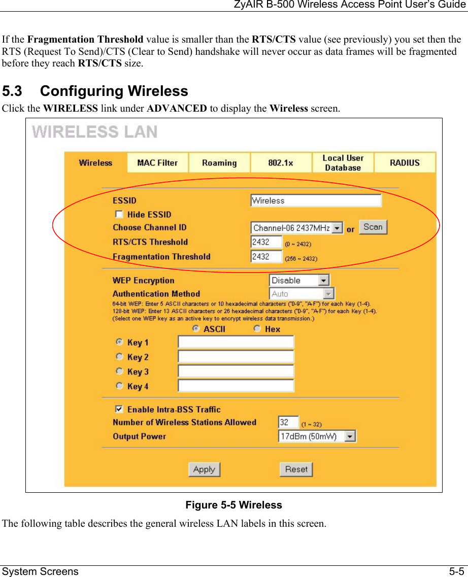
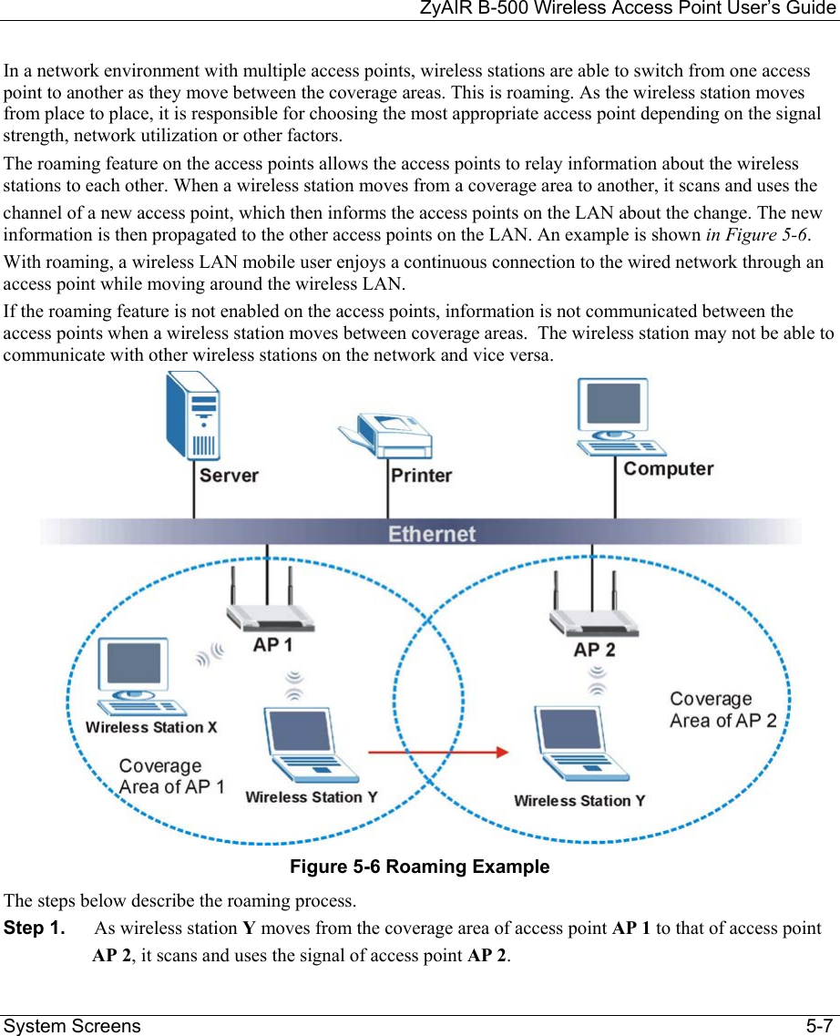
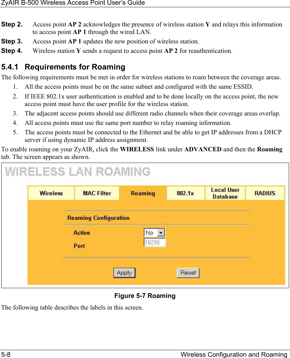
ZyXEL Communications B500 Wireless LAN Access Point User Manual P650H 17 ADSL Router User s Guide
ZyXEL Communications Corporation Wireless LAN Access Point P650H 17 ADSL Router User s Guide
Contents
- 1. Users Manual 1
- 2. Users Manual 2
Users Manual 1
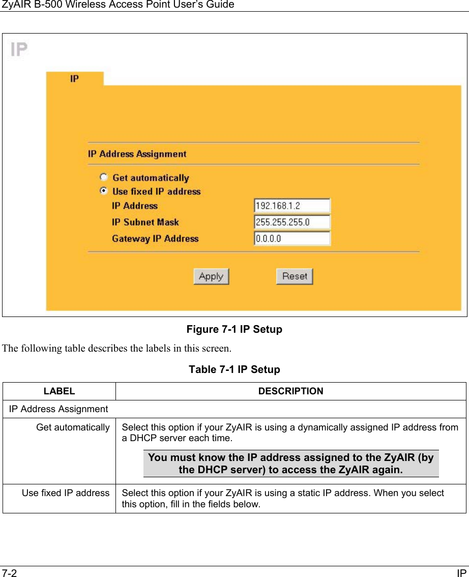
![ZyAIR B-500 Wireless Access Point User’s Guide Preface xv Preface Congratulations on your purchase from the ZyAIR B-500 Wireless Access Point. An access point (AP) acts as a bridge between the wireless and wired networks, extending your existing wired network without any additional wiring. This User’s Guide is designed to guide you through the configuration of your ZyAIR using the web configurator or the SMT. Use the web configurator, System Management Terminal (SMT) or command interpreter interface to configure your ZyAIR. Not all features can be configured through all interfaces. The web configurator parts of this guide contain background information on features configurable by the web configurator and the SMT. The SMT parts of this guide contain background information solely on features not configurable by the web configurator. Don’t forget to register your product online for free future product updates and information at www.zyxel.com for global products, or at www.us.zyxel.com for North American products. Related Documentation Supporting Disk Refer to the included CD for support documents. Quick Installation Guide Our Quick Installation Guide is designed to help you get up and running right away. It contains information on the configuration of key features and hardware connections and installation. ZyXEL Web Site The ZyXEL download library at www.zyxel.com contains additional support documentation. Please also refer to www.zyxel.com for an online glossary of networking terms. Syntax Conventions • “Enter” means for you to type one or more characters (and press the carriage return). “Select” or “Choose” means for you to use one predefined choices. • Enter, or carriage return, key; [ESC] means the escape key and [SPACE BAR] means the space bar. [UP] and [DOWN] are the up and down arrow keys.](https://usermanual.wiki/ZyXEL-Communications/B500.Users-Manual-1/User-Guide-378792-Page-15.png)