ZyXEL Communications B500 Wireless LAN Access Point User Manual P650H 17 ADSL Router User s Guide
ZyXEL Communications Corporation Wireless LAN Access Point P650H 17 ADSL Router User s Guide
Contents
- 1. Users Manual 1
- 2. Users Manual 2
Users Manual 2
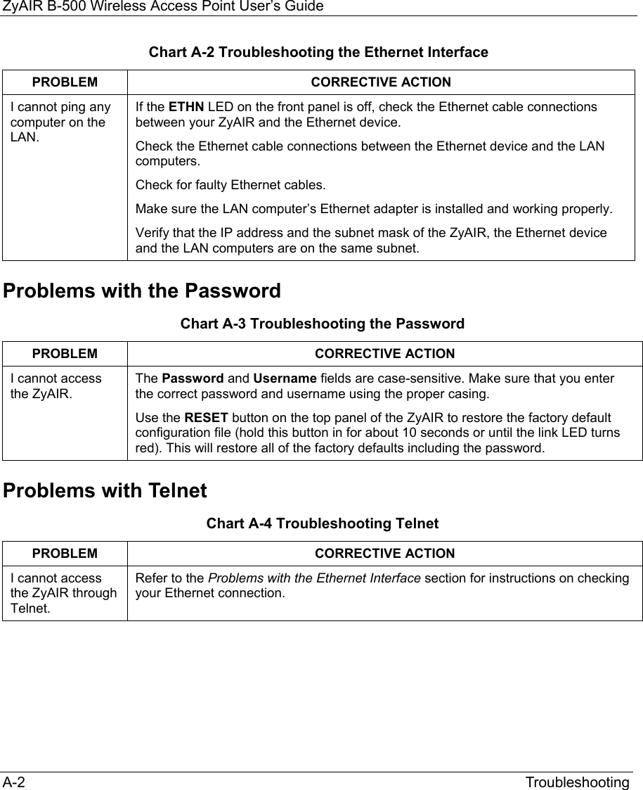
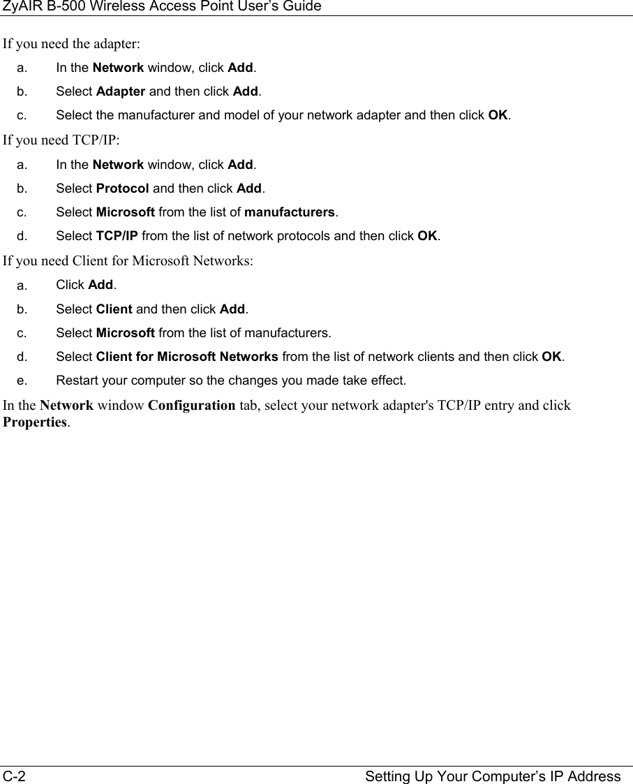
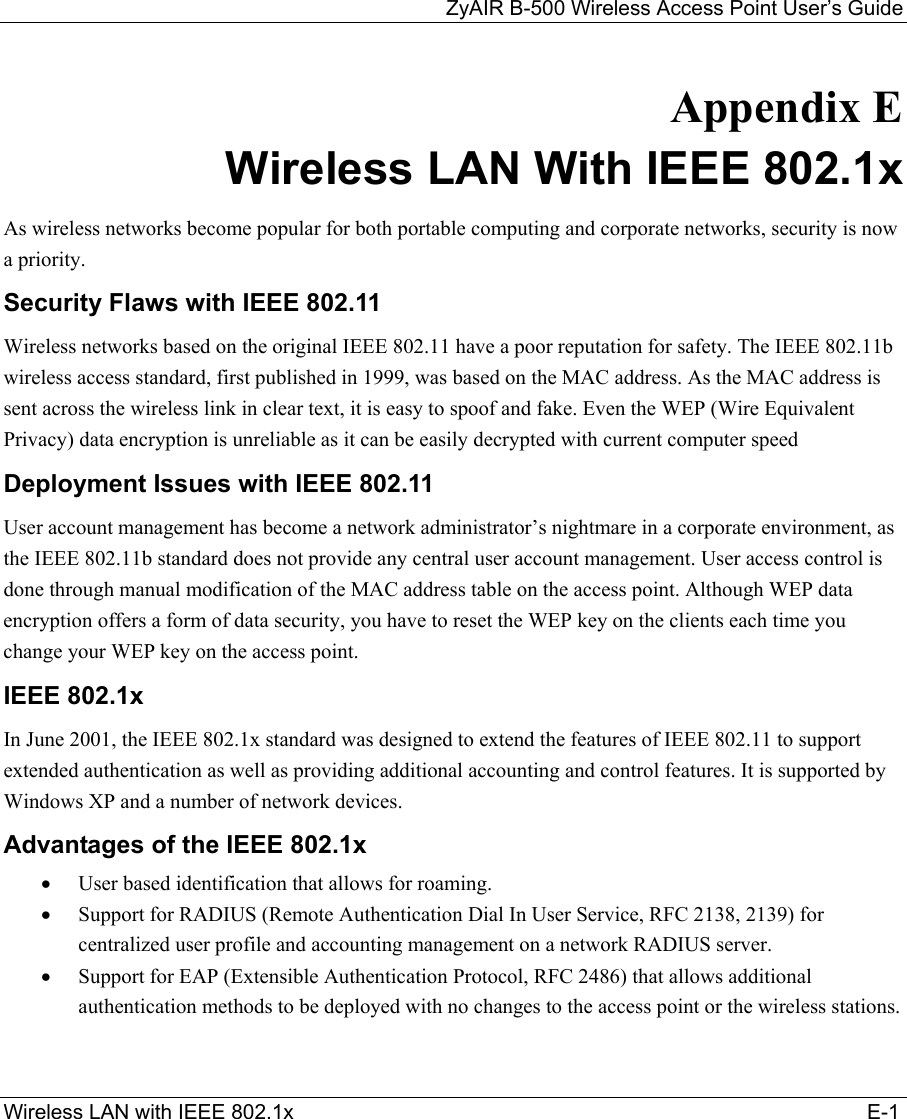
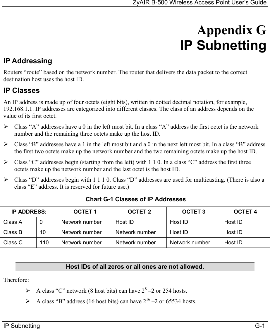
![ZyAIR B-500 Wireless Access Point User’s Guide Introducing the SMT 10-1 Chapter 10 Introducing the SMT This chapter describes how to access the SMT and provides an overview of its menus. 10.1 Connect to your ZyAIR Using Telnet The following procedure details how to telnet into your ZyAIR. Step 1. In Windows, click Start (usually in the bottom left corner), Run and then type “telnet 192.168.1.2” (the default IP address) and click OK. Step 2. For your first login, enter the default password “1234”. As you type the password, the screen displays an asterisk “*” for each character you type. Figure 10-1 Login Screen Step 3. After entering the password you will see the main menu. Please note that if there is no activity for longer than five minutes (default timeout period) after you log in, your ZyAIR will automatically log you out. You will then have to telnet into the ZyAIR again. You can use the web configurator or the CI commands to change the inactivity time out period. 10.2 Changing the System Password Change the ZyAIR default password by following the steps shown next. Step 1. From the main menu, enter 23 to display Menu 23 – System Security. Step 2. Enter 1 to display Menu 23.1 – System Security – Change Password as shown next. Step 3. Type your existing system password in the Old Password field, and press [ENTER]. Password : ****](https://usermanual.wiki/ZyXEL-Communications/B500.Users-Manual-2/User-Guide-378793-Page-3.png)
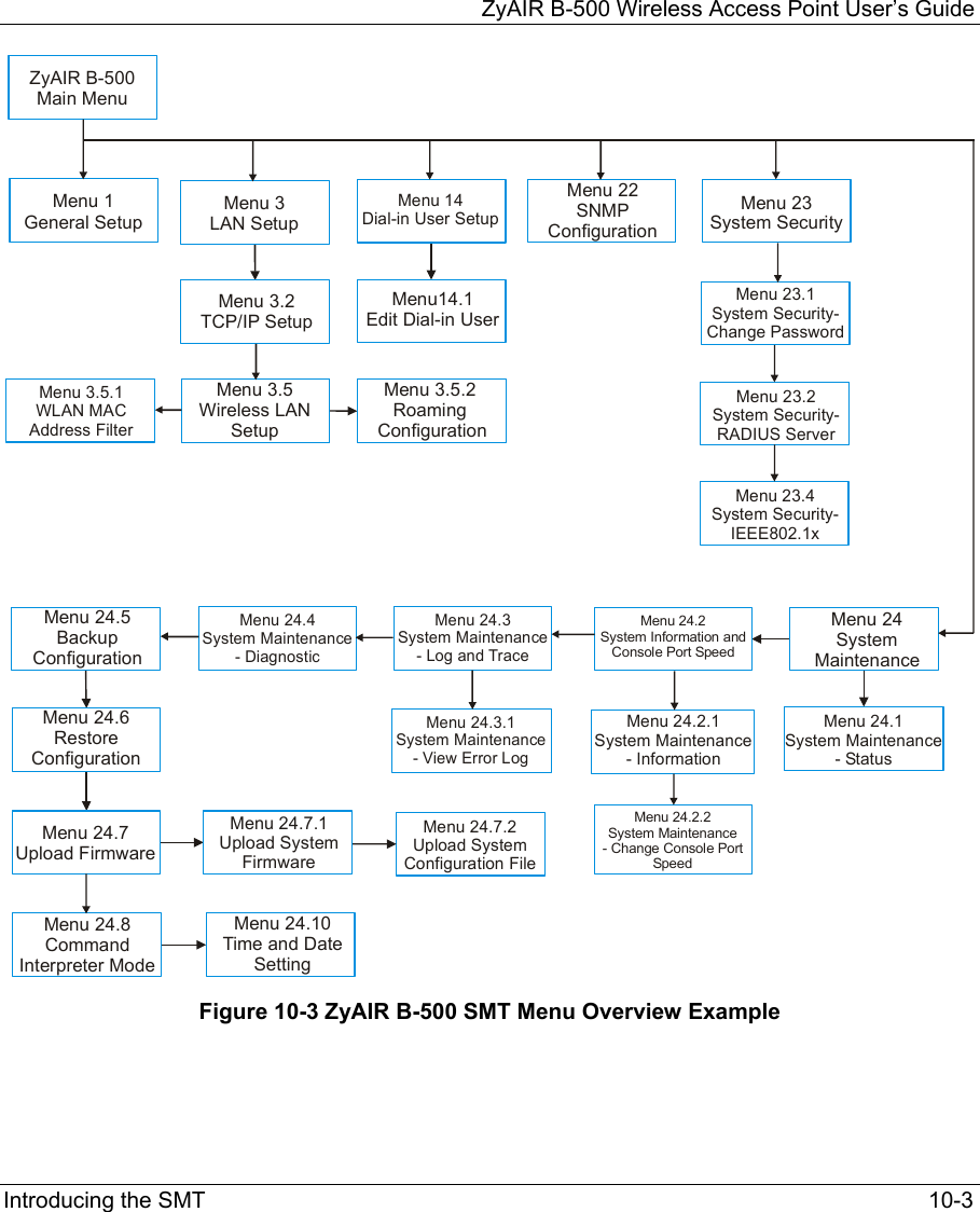
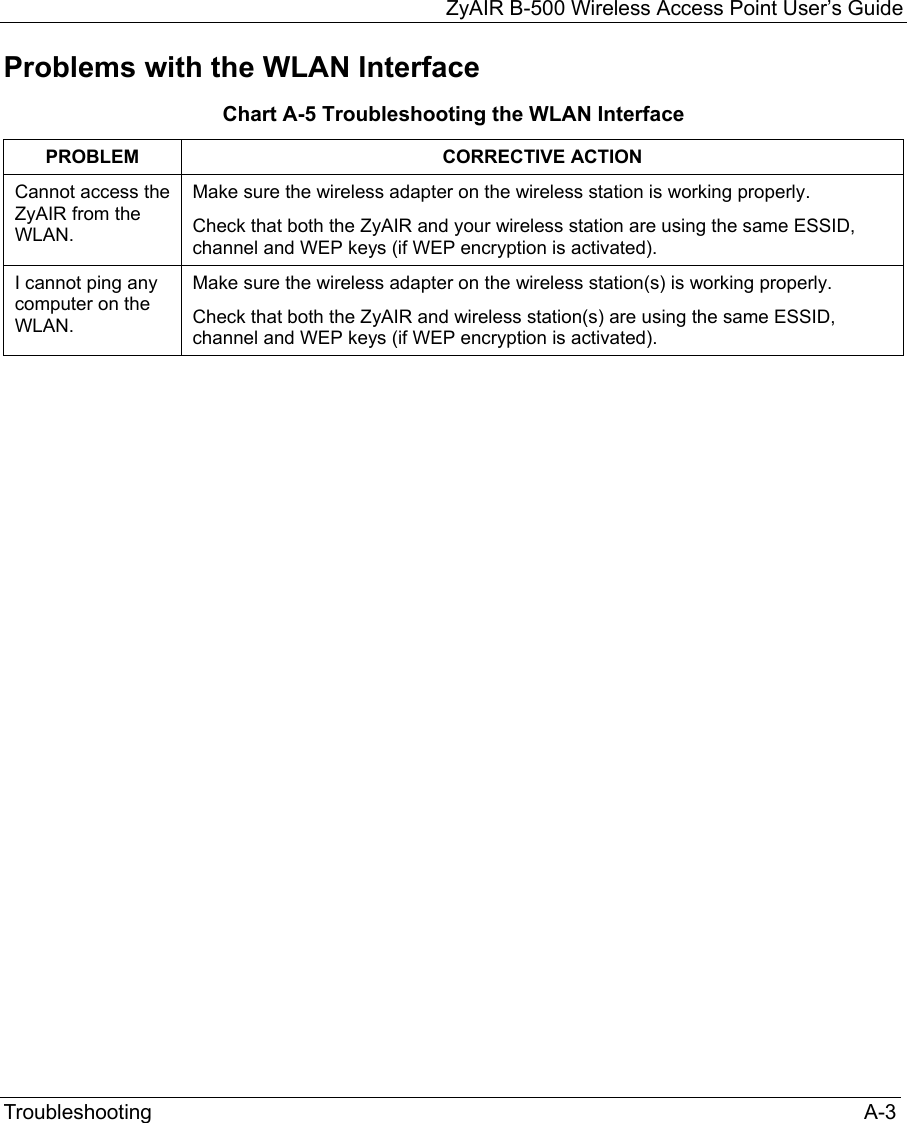
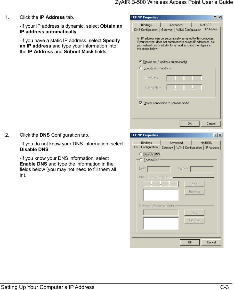
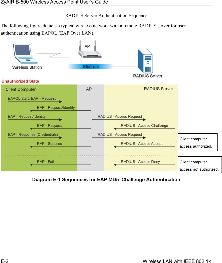
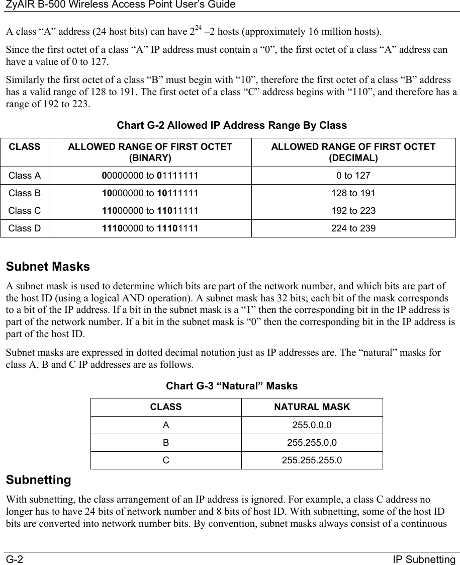
![ZyAIR B-500 Wireless Access Point User’s Guide 10-2 Introducing the SMT Figure 10-2 Menu 23.1 System Security : Change Password Step 4. Type your new system password in the New Password field (up to 30 characters), and press [ENTER]. Step 5. Re-type your new system password in the Retype to confirm field for confirmation and press [ENTER]. Note that as you type a password, the screen displays an asterisk “*” for each character you type. 10.3 ZyAIR SMT Menu Overview Example The following figure gives you an example overview of the various SMT menu screens for your ZyAIR. Menu 23.1 – System Security – Change Password Old Password= **** New Password= ? Retype to confirm= ? Enter here to CONFIRM or ESC to CANCEL:](https://usermanual.wiki/ZyXEL-Communications/B500.Users-Manual-2/User-Guide-378793-Page-4.png)
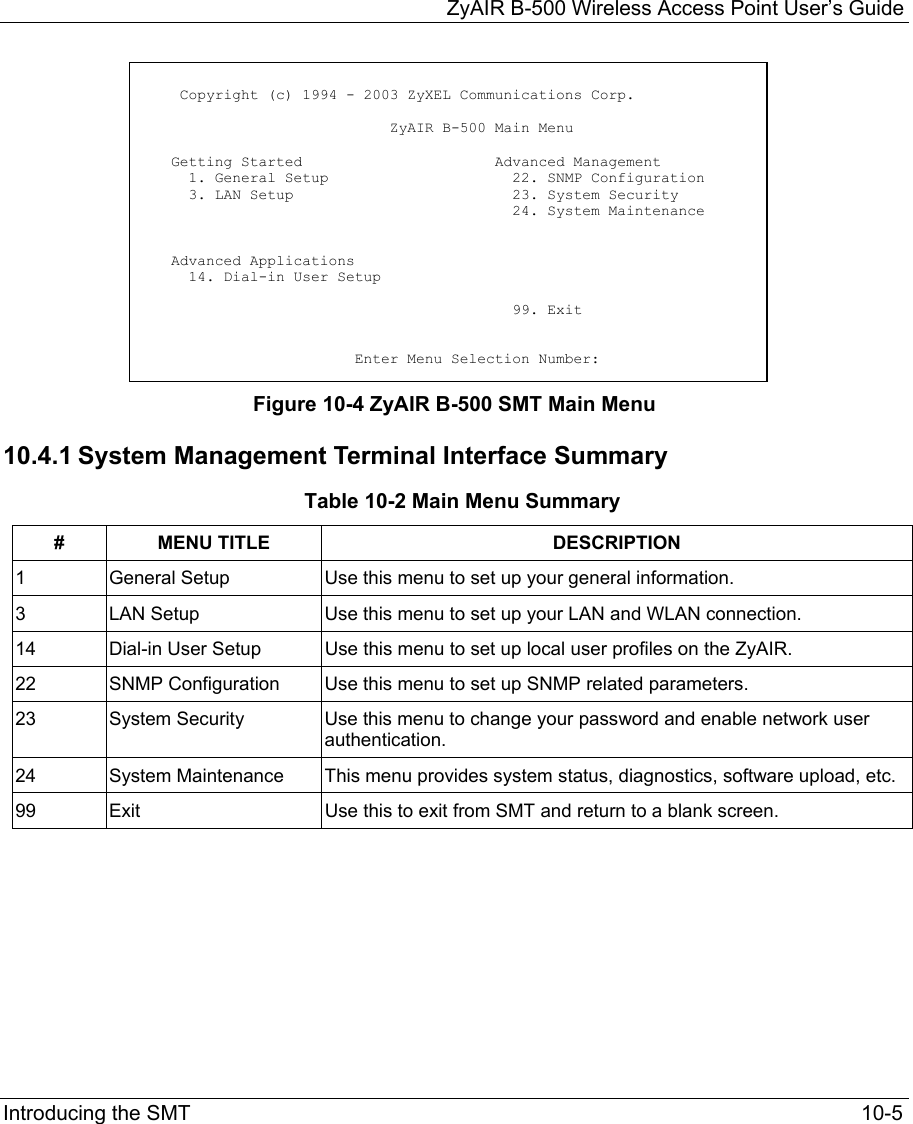
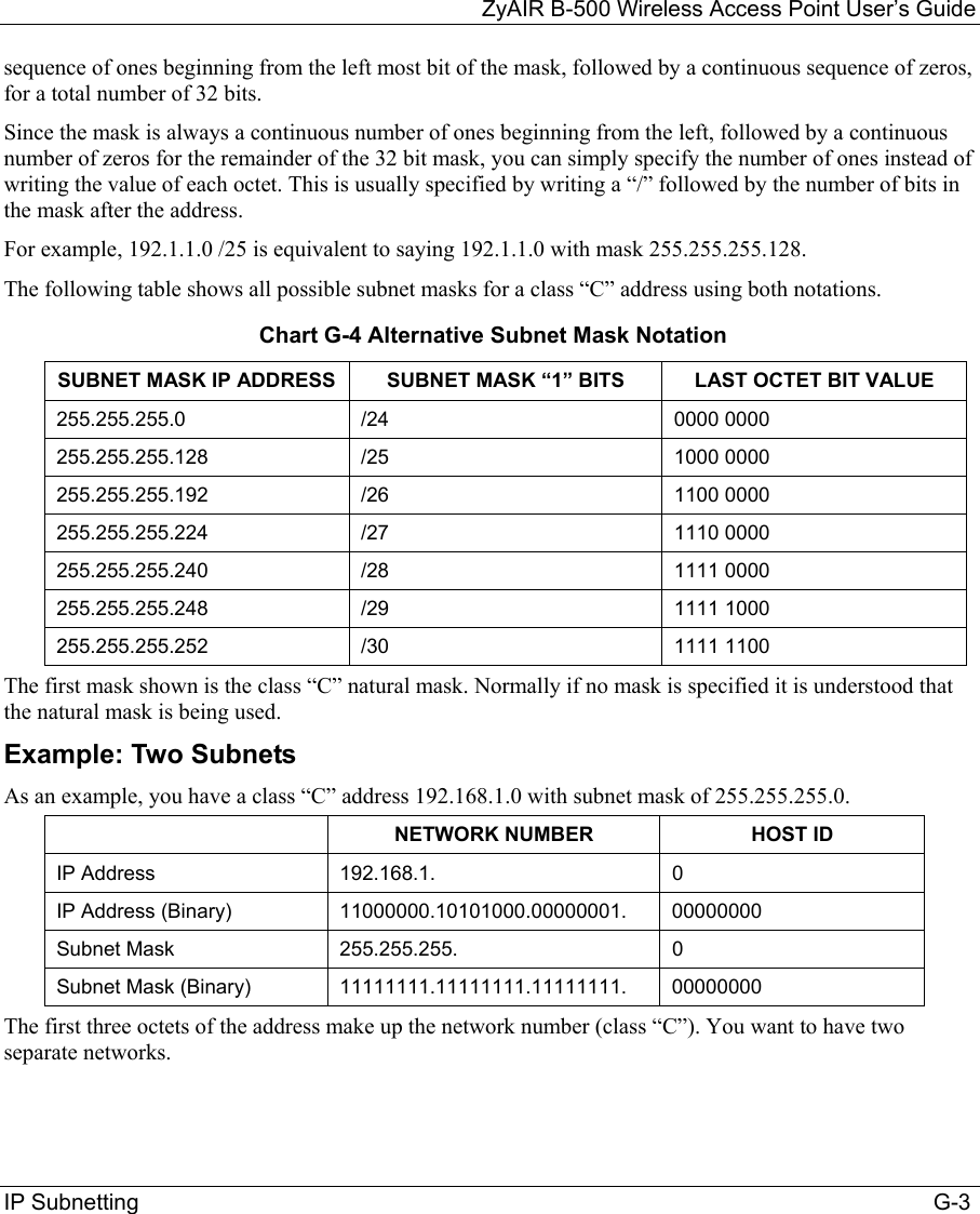
![ZyAIR B-500 Wireless Access Point User’s Guide 10-4 Introducing the SMT 10.4 Navigating the SMT Interface The SMT (System Management Terminal) is the interface that you use to configure your ZyAIR. Several operations that you should be familiar with before you attempt to modify the configuration are listed in the table below. Table 10-1 Main Menu Commands OPERATION KEYSTROKE DESCRIPTION Move down to another menu [ENTER] To move forward to a submenu, type in the number of the desired submenu and press [ENTER]. Move up to a previous menu [ESC] Press [ESC] to move back to the previous menu. Move to a “hidden” menu Press [SPACE BAR] to change No to Yes then press [ENTER]. Fields beginning with “Edit” lead to hidden menus and have a default setting of No. Press [SPACE BAR] once to change No to Yes, then press [ENTER] to go to the “hidden” menu. Move the cursor [ENTER] or [UP]/[DOWN] arrow keys. Within a menu, press [ENTER] to move to the next field. You can also use the [UP]/[DOWN] arrow keys to move to the previous and the next field, respectively. Entering information Type in or press [SPACE BAR], then press [ENTER]. You need to fill in two types of fields. The first requires you to type in the appropriate information. The second allows you to cycle through the available choices by pressing [SPACE BAR]. Required fields <?> or ChangeMe All fields with the symbol <?> must be filled in order to be able to save the new configuration. All fields with ChangeMe must not be left blank in order to be able to save the new configuration. N/A fields <N/A> Some of the fields in the SMT will show a <N/A>. This symbol refers to an option that is Not Applicable. Save your configuration [ENTER] Save your configuration by pressing [ENTER] at the message “Press ENTER to confirm or ESC to cancel”. Saving the data on the screen will take you, in most cases to the previous menu. Exit the SMT Type 99, then press [ENTER]. Type 99 at the main menu prompt and press [ENTER] to exit the SMT interface. After you enter the password, the SMT displays the main menu, as shown next.](https://usermanual.wiki/ZyXEL-Communications/B500.Users-Manual-2/User-Guide-378793-Page-6.png)
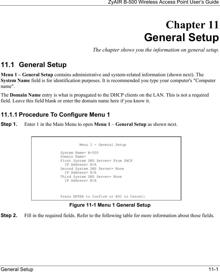
![ZyAIR B-500 Wireless Access Point User’s Guide 11-2 General Setup Table 11-1 Menu 1 General Setup FIELD DESCRIPTION EXAMPLE System Name Choose a descriptive name for identification purposes. This name can be up to 30 alphanumeric characters long. Spaces are not allowed, but dashes “-” and underscores "_" are accepted. B-500 Domain Name This is not a required field. Leave this field blank or enter the domain name here if you know it. First/Second/Third System DNS Server Press [SPACE BAR] to select From DHCP, User Defined or None and press [ENTER]. These fields are not available on all models. From DHCP IP Address Enter the IP addresses of the DNS servers. This field is available when you select User-Defined in the field above. N/A When you have completed this menu, press [ENTER] at the prompt “Press ENTER to Confirm…” to save your configuration, or press [ESC] at any time to cancel.](https://usermanual.wiki/ZyXEL-Communications/B500.Users-Manual-2/User-Guide-378793-Page-10.png)
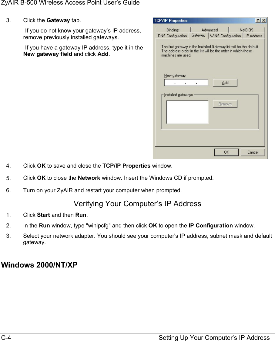
![ZyAIR B-500 Wireless Access Point User’s Guide LAN Setup 12-1 Chapter 12 LAN Setup This chapter shows you how to configure the LAN on your ZyAIR.. 12.1 LAN Setup This section describes how to configure the Ethernet using Menu 3 – LAN Setup. From the main menu, enter 3 to display menu 3. Figure 12-1 Menu 3 LAN Setup 12.2 TCP/IP Ethernet Setup Use menu 3.2 to configure your ZyAIR for TCP/IP. To edit menu 3.2, enter 3 from the main menu to display Menu 3-LAN Setup. When menu 3 appears, press 2 and press [ENTER] to display Menu 3.2-TCP/IP Setup, as shown next. Figure 12-2 Menu 3.2 TCP/IP Setup Follow the instructions in the following table on how to configure the fields in this menu. Menu 3 - LAN Setup 2. TCP/IP Setup 5. Wireless LAN Setup Enter Menu Selection Number: Menu 3.2 - TCP/IP Setup IP Address Assignment= Static IP Address= 192.168.1.2 IP Subnet Mask= 255.255.255.0 Gateway IP Address= 0.0.0.0 Press ENTER to Confirm or ESC to Cancel:](https://usermanual.wiki/ZyXEL-Communications/B500.Users-Manual-2/User-Guide-378793-Page-11.png)
![ZyAIR B-500 Wireless Access Point User’s Guide 12-2 LAN Setup Table 12-1 Menu 3.2 TCP/IP Setup FIELD DESCRIPTION EXAMPLE IP Address Assignment Press [SPACE BAR] and then [ENTER] to select Dynamic to have the ZyAIR obtain an IP address from a DHCP server. You must know the IP address assigned to the ZyAIR (by the DHCP server) to access the ZyAIR again. Select Static to give the ZyAIR a fixed, unique IP address. Enter a subnet mask appropriate to your network and the gateway IP address if applicable. IP Address Enter the (LAN) IP address of your ZyAIR in dotted decimal notation 192.168.1.2 IP Subnet Mask Your ZyAIR will automatically calculate the subnet mask based on the IP address that you assign. Unless you are implementing subnetting, use the subnet mask computed by the ZyAIR. 255.255.255.0 Gateway IP Address Type the IP address of the gateway. The gateway is an immediate neighbor of your ZyAIR that will forward the packet to the destination. On the LAN, the gateway must be a router on the same network segment as your ZyAIR. When you have completed this menu, press [ENTER] at the prompt “Press ENTER to Confirm…” to save your configuration, or press [ESC] at any time to cancel. 12.3 Wireless LAN Setup Use menu 3.5 to set up your ZyAIR as the wireless access point. To edit menu 3.5, enter 3 from the main menu to display Menu 3 – LAN Setup. When menu 3 appears, press 5 and then press [ENTER] to display Menu 3.5 – Wireless LAN Setup as shown next.](https://usermanual.wiki/ZyXEL-Communications/B500.Users-Manual-2/User-Guide-378793-Page-12.png)
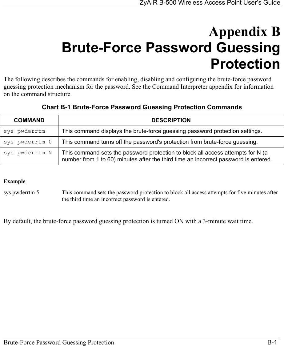
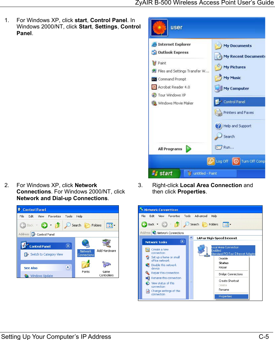
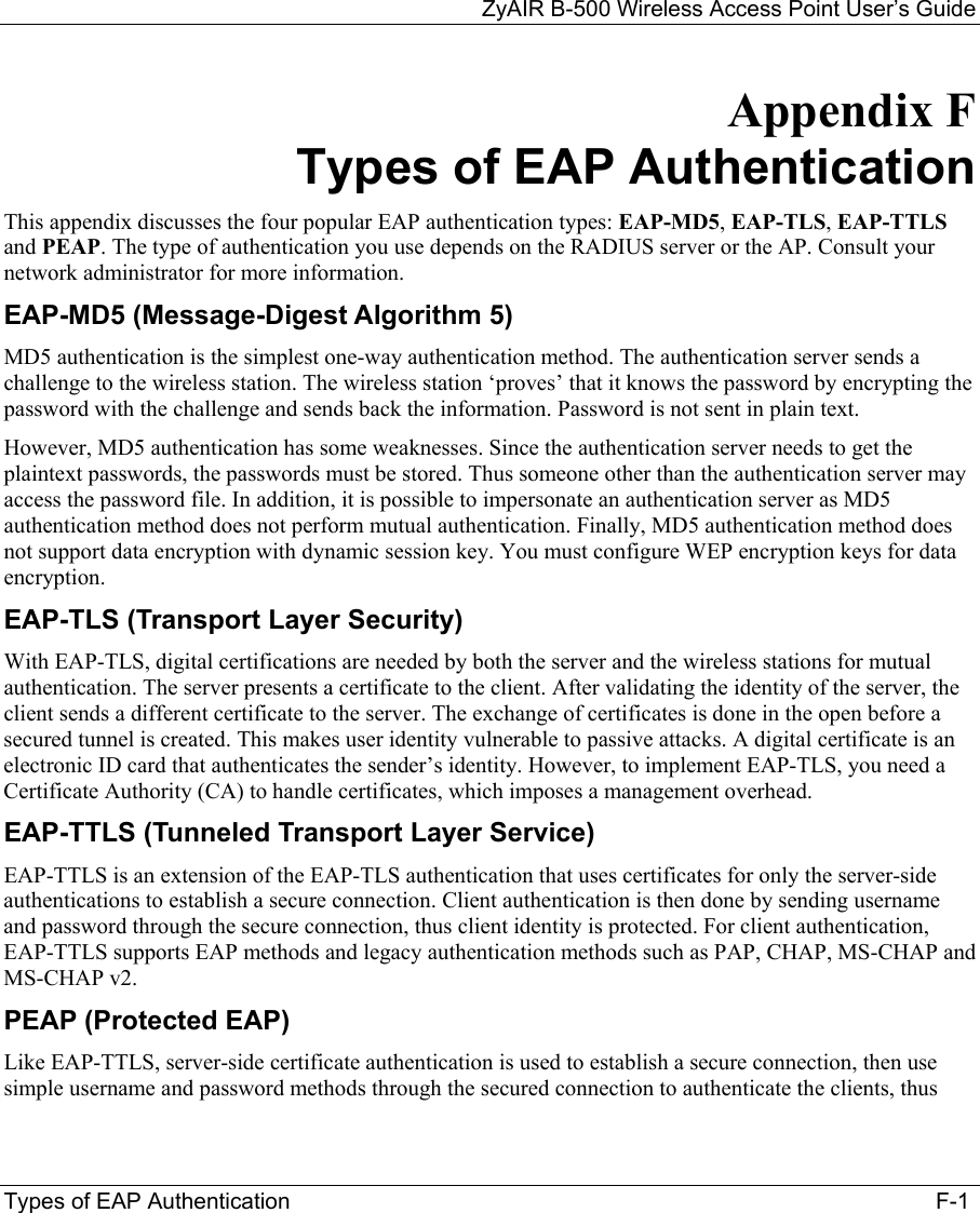
![ZyAIR B-500 Wireless Access Point User’s Guide LAN Setup 12-3 Figure 12-3 Menu 3.5 Wireless LAN Setup The following table describes the fields in this menu. Table 12-2 Menu 3.5 Wireless LAN Setup FIELD DESCRIPTION EXMAPLEESSID The ESSID (Extended Service Set IDentity) identifies the AP the wireless station is to associate to. Wireless stations associating to the AP must have the same ESSID. Enter a descriptive name up to 32 printable 7-bit ASCII characters. Wireless Hide ESSID Press [SPACE BAR] and select Yes to hide the ESSID in the outgoing data frame so an intruder cannot obtain the ESSID through passive scanning. No Channel ID Press [SPACE BAR] to select a channel. This allows you to set the operating frequency/channel depending on your particular region. CH01 2412MHz RTS Threshold Setting this attribute to zero turns on the RTS/CTS handshake. Enter a value between 0 and 2432. 2432 Frag. Threshold This is the maximum data fragment size that can be sent. Enter a value between 256 and 2432. 2432 WEP Encryption Select Disable to allow wireless stations to communicate with the access points without any data encryption. Select 64-bit WEP or 128-bit WEP to enable data encryption. Disable Menu 3.5 - Wireless LAN Setup ESSID= Wireless Hide ESSID= No Channel ID= CH06 2437MHz RTS Threshold= 2432 Frag. Threshold= 2432 WEP Encryption= Disable Default Key= N/A Key1= N/A Key2= N/A Key3= N/A Key4= N/A Authen. Method= N/A Edit MAC Address Filter= No Edit Roaming Configuration= No Block Intra-BSS Traffic= No Number of Associated Stations= 32 Output Power= 17dBm Press ENTER to Confirm or ESC to Cancel:](https://usermanual.wiki/ZyXEL-Communications/B500.Users-Manual-2/User-Guide-378793-Page-13.png)
![ZyAIR B-500 Wireless Access Point User’s Guide 12-4 LAN Setup Table 12-2 Menu 3.5 Wireless LAN Setup FIELD DESCRIPTION EXMAPLEDefault Key Enter the key number (1 to 4) in this field. Only one key can be enabled at any one time. This key must be the same on the ZyAIR and the wireless stations to communicate. 1 Key 1 to Key 4 The WEP keys are used to encrypt data. Both the ZyAIR and the wireless stations must use the same WEP key for data transmission. If you chose 64-bit WEP in the WEP Encryption field, then enter any 5 ASCII characters or 10 hexadecimal characters ("0-9", "A-F"). If you chose 128-bit WEP in the WEP Encryption field, then enter 13 ASCII characters or 26 hexadecimal characters ("0-9", "A-F"). Enter “0x” before the key to denote a hexadecimal key. Don’t enter “0x” before the key to denote an ASCII key. 0x12345abcde Authen. Method Press [SPACE BAR] to select Auto, Open System Only or Shared Key Only and press [ENTER]. This field is N/A if WEP is not activated. If WEP encryption is activated, the default setting is Auto. Auto Edit MAC Address Filter Press [SPACE BAR] to select Yes and press [ENTER] to display menu 3.5.1. See the section on MAC address filter for more information. No Edit Roaming Configuration Press [SPACE BAR] to select Yes and press [ENTER] to display menu 3.5.2. See the section on roaming configuration for more information. No Block Intra-BSS Traffic Press [SPACE BAR] to select Yes or No and press [ENTER]. No Number of Association Stations Enter the number of association stations. The number should be from 1 to 32. 32 Output Power Press [SPACE BAR] to select 11dBm, 14dBm or 17dBm and press [ENTER]. 17dBm When you have completed this menu, press [ENTER] at the prompt “Press ENTER to confirm or ESC to cancel” to save your configuration or press [ESC] to cancel and go back to the previous screen.](https://usermanual.wiki/ZyXEL-Communications/B500.Users-Manual-2/User-Guide-378793-Page-14.png)
![ZyAIR B-500 Wireless Access Point User’s Guide LAN Setup 12-5 12.3.1 Configuring MAC Address Filter Your ZyAIR checks the MAC address of the wireless station device against a list of allowed or denied MAC addresses. However, intruders could fake allowed MAC addresses so MAC-based authentication is less secure than EAP authentication. Follow the steps below to create the MAC address table on your ZyAIR. Step 1. From the main menu, enter 3 to open Menu 3 – LAN Setup. Step 2. Enter 5 to display Menu 3.5 – Wireless LAN Setup. Figure 12-4 Menu 3.5 Wireless LAN Setup Step 3. In the Edit MAC Address Filter field, press [SPACE BAR] to select Yes and press [ENTER]. Menu 3.5.1 – WLAN MAC Address Filter displays as shown next. Menu 3.5 - Wireless LAN Setup ESSID= Wireless Hide ESSID= No Channel ID= CH06 2437MHz RTS Threshold= 2432 Frag. Threshold= 2432 WEP Encryption= Disable Default Key= N/A Key1= N/A Key2= N/A Key3= N/A Key4= N/A Authen. Method= N/A Edit MAC Address Filter= Yes Edit Roaming Configuration= No Block Intra-BSS Traffic= No Number of Associated Stations= 32 Output Power= 17dBm Press ENTER to Confirm or ESC to Cancel:](https://usermanual.wiki/ZyXEL-Communications/B500.Users-Manual-2/User-Guide-378793-Page-15.png)
![ZyAIR B-500 Wireless Access Point User’s Guide 12-6 LAN Setup Figure 12-5 Menu 3.5.1 WLAN MAC Address Filter The following table describes the fields in this menu. Table 12-3 Menu 3.5.1 WLAN MAC Address Filter FIELD DESCRIPTION Active To enable MAC address filtering, press [SPACE BAR] to select Yes and press [ENTER]. Filter Action Define the filter action for the list of MAC addresses in the MAC address filter table. To deny access to the ZyAIR, press [SPACE BAR] to select Deny Association and press [ENTER]. MAC addresses not listed will be allowed to access the ZyAIR. The default action, Allowed Association, permits association with the ZyAIR. MAC addresses not listed will be denied access to the ZyAIR. MAC Address Filter 1..32 Enter the MAC addresses (in XX:XX:XX:XX:XX:XX format) of the client computers that are allowed or denied access to the ZyAIR in these address fields. When you have completed this menu, press [ENTER] at the prompt “Press ENTER to confirm or ESC to cancel” to save your configuration or press [ESC] to cancel and go back to the previous screen. Menu 3.5.1 - WLAN MAC Address Filter Active= No Filter Action= Allowed Association ------------------------------------------------------------------------------ 1= 00:00:00:00:00:00 13= 00:00:00:00:00:00 25= 00:00:00:00:00:00 2= 00:00:00:00:00:00 14= 00:00:00:00:00:00 26= 00:00:00:00:00:00 3= 00:00:00:00:00:00 15= 00:00:00:00:00:00 27= 00:00:00:00:00:00 4= 00:00:00:00:00:00 16= 00:00:00:00:00:00 28= 00:00:00:00:00:00 5= 00:00:00:00:00:00 17= 00:00:00:00:00:00 29= 00:00:00:00:00:00 6= 00:00:00:00:00:00 18= 00:00:00:00:00:00 30= 00:00:00:00:00:00 7= 00:00:00:00:00:00 19= 00:00:00:00:00:00 31= 00:00:00:00:00:00 8= 00:00:00:00:00:00 20= 00:00:00:00:00:00 32= 00:00:00:00:00:00 9= 00:00:00:00:00:00 21= 00:00:00:00:00:00 10= 00:00:00:00:00:00 22= 00:00:00:00:00:00 11= 00:00:00:00:00:00 23= 00:00:00:00:00:00 12= 00:00:00:00:00:00 24= 00:00:00:00:00:00 ------------------------------------------------------------------------------ Enter here to CONFIRM or ESC to CANCEL:](https://usermanual.wiki/ZyXEL-Communications/B500.Users-Manual-2/User-Guide-378793-Page-16.png)
![ZyAIR B-500 Wireless Access Point User’s Guide LAN Setup 12-7 12.3.2 Configuring Roaming Enable the roaming feature if you have two or more ZyAIRs on the same subnet. Follow the steps below to allow roaming on your ZyAIR. Step 1. From the main menu, enter 3 to display Menu 3 – LAN Setup. Step 2. Enter 5 to display Menu 3.5 – Wireless LAN Setup. Figure 12-6 Menu 3.5 Wireless LAN Setup Step 3. Move the cursor to the Edit Roaming Configuration field. Press [SPACE BAR] to select Yes and then press [ENTER]. Menu 3.5.2 – Roaming Configuration displays as shown next. Figure 12-7 Menu 3.5.2 Roaming Configuration The following table describes the fields in this menu. Menu 3.5.2 - Roaming Configuration Active= Yes Port #= 16290 Press ENTER to Confirm or ESC to Cancel: Menu 3.5 - Wireless LAN Setup ESSID= Wireless Hide ESSID= No Channel ID= CH06 2437MHz RTS Threshold= 2432 Frag. Threshold= 2432 WEP Encryption= Disable Default Key= N/A Key1= N/A Key2= N/A Key3= N/A Key4= N/A Authen. Method= N/A Edit MAC Address Filter= No Edit Roaming Configuration= Yes Block Intra-BSS Traffic= No Number of Associated Stations= 32 Output Power= 17dBm Press ENTER to Confirm or ESC to Cancel:](https://usermanual.wiki/ZyXEL-Communications/B500.Users-Manual-2/User-Guide-378793-Page-17.png)
![ZyAIR B-500 Wireless Access Point User’s Guide 12-8 LAN Setup Table 12-4 Menu 3.5.2 Roaming Configuration FIELD DESCRIPTION Active Press [SPACE BAR] and then [ENTER] to select Yes to enable roaming on the ZyAIR if you have two or more ZyAIRs on the same subnet. Port # Type the port number to communicate roaming information between access points. The port number must be the same on all access points. The default is 16290. Make sure this port is not used by other services. When you have completed this menu, press [ENTER] at the prompt “Press ENTER to confirm or ESC to cancel” to save your configuration or press [ESC] to cancel and go back to the previous screen.](https://usermanual.wiki/ZyXEL-Communications/B500.Users-Manual-2/User-Guide-378793-Page-18.png)
![ZyAIR B-500 Wireless Access Point User’s Guide Dial-in User Setup 13-1 Chapter 13 Dial-in User Setup This chapter shows you how to create user accounts on the ZyAIR. 13.1 Dial-in User Setup By storing user profiles locally, your ZyAIR is able to authenticate wireless users without interacting with a network RADIUS server. Follow the steps below to set up user profiles on your ZyAIR. Step 1. From the main menu, enter 14 to display Menu 14 - Dial-in User Setup. Figure 13-1 Menu 14- Dial-in User Setup Step 2. Type a number and press [ENTER] to edit the user profile. Figure 13-2 Menu 14.1- Edit Dial-in User The following table describes the fields in this screen. Menu 14 - Dial-in User Setup 1. ________ 9. ________ 17. ________ 25. ________ 2. ________ 10. ________ 18. ________ 26. ________ 3. ________ 11. ________ 19. ________ 27. ________ 4. ________ 12. ________ 20. ________ 28. ________ 5. ________ 13. ________ 21. ________ 29. ________ 6. ________ 14. ________ 22. ________ 30. ________ 7. ________ 15. ________ 23. ________ 31. ________ 8. ________ 16. ________ 24. ________ 32. ________ Enter Menu Selection Number: Menu 14.1 - Edit Dial-in User User Name= test Active= Yes Password= ******** Press ENTER to Confirm or ESC to Cancel:](https://usermanual.wiki/ZyXEL-Communications/B500.Users-Manual-2/User-Guide-378793-Page-19.png)
![ZyAIR B-500 Wireless Access Point User’s Guide 13-2 Dial-in User Setup Table 13-1 Menu 14.1- Edit Dial-in User FIELD DESCRIPTION User Name Enter a username up to 31 alphanumeric characters long for this user profile. This field is case sensitive. Active Press [SPACE BAR] to select Yes and press [ENTER] to enable the user profile. Password Enter a password up to 31 characters long for this user profile. When you have completed this menu, press [ENTER] at the prompt “Press ENTER to confirm or ESC to cancel” to save your configuration or press [ESC] to cancel and go back to the previous screen.](https://usermanual.wiki/ZyXEL-Communications/B500.Users-Manual-2/User-Guide-378793-Page-20.png)
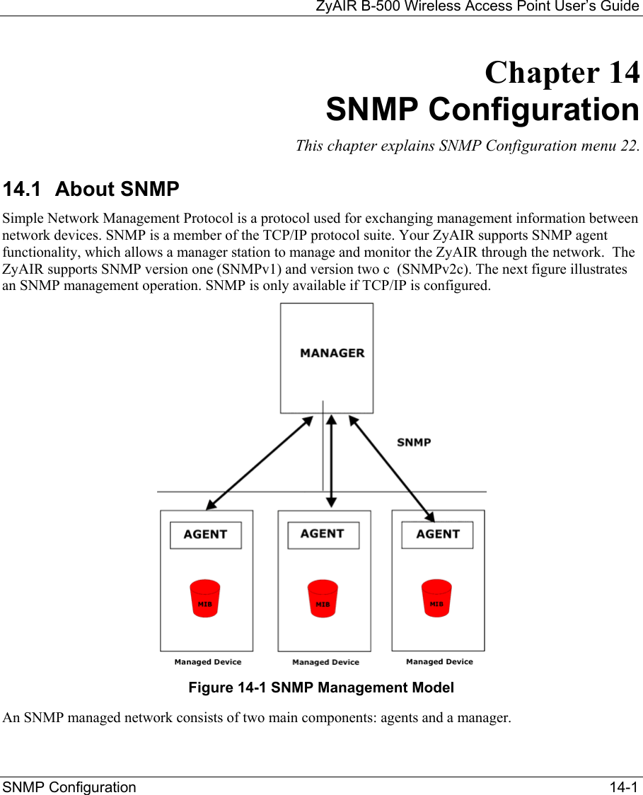
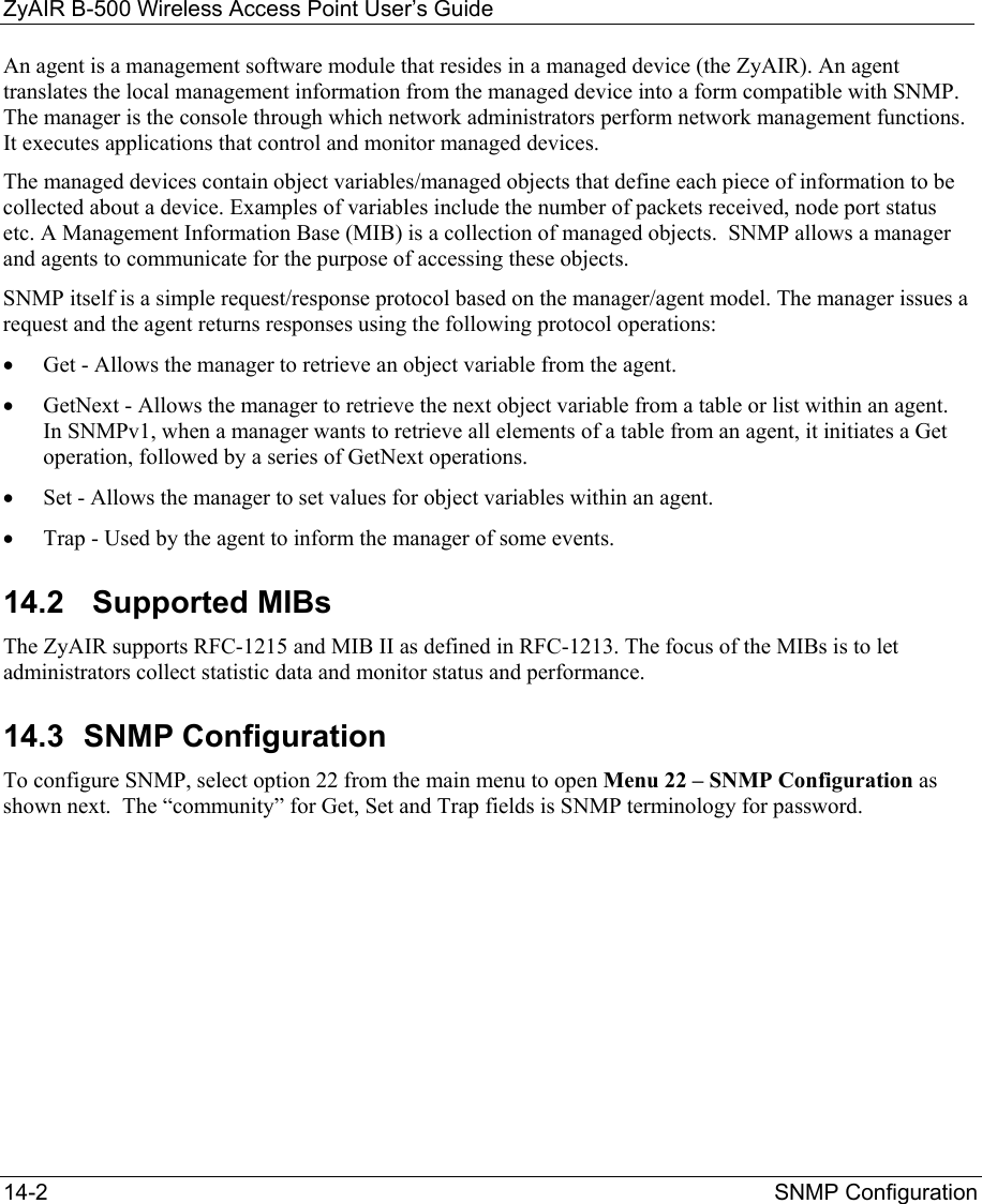
![ZyAIR B-500 Wireless Access Point User’s Guide SNMP Configuration 14-3 Figure 14-2 Menu 22 SNMP Configuration The following table describes the SNMP configuration parameters. Table 14-1 Menu 22 SNMP Configuration FIELD DESCRIPTION EXAMPLE SNMP: Get Community Type the Get Community, which is the password for the incoming Get- and GetNext requests from the management station. public Set Community Type the Set Community, which is the password for incoming Set requests from the management station. public Trusted Host If you enter a trusted host, your ZyAIR will only respond to SNMP messages from this address. A blank (default) field means your ZyAIR will respond to all SNMP messages it receives, regardless of source. 0.0.0.0 Trap: Community Type the trap community, which is the password sent with each trap to the SNMP manager. public Destination Type the IP address of the station to send your SNMP traps to. 0.0.0.0 When you have completed this menu, press [ENTER] at the prompt “Press ENTER to confirm or ESC to cancel” to save your configuration or press [ESC] to cancel and go back to the previous screen. 14.4 SNMP Traps The ZyAIR will send traps to the SNMP manager when any one of the following events occurs: Menu 22 - SNMP Configuration SNMP: Get Community= public Set Community= public Trusted Host= 0.0.0.0 Trap: Community= public Destination= 0.0.0.0 Press ENTER to Confirm or ESC to Cancel:](https://usermanual.wiki/ZyXEL-Communications/B500.Users-Manual-2/User-Guide-378793-Page-23.png)
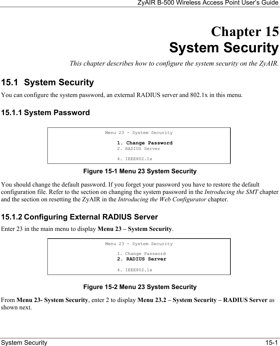
![ZyAIR B-500 Wireless Access Point User’s Guide 15-2 System Security Figure 15-3 Menu 23.2 System Security : RADIUS Server The following table describes the fields in this menu. Table 15-1 Menu 23.2 System Security : RADIUS Server FIELD DESCRIPTION EXAMPLE Authentication Server Active Press [SPACE BAR] to select Yes and press [ENTER] to enable user authentication through an external authentication server. No Server Address Enter the IP address of the external authentication server in dotted decimal notation. 10.11.12.13 Port The default port of the RADIUS server for authentication is 1812. You need not change this value unless your network administrator instructs you to do so with additional information. 1812 Shared Secret Specify a password (up to 31 alphanumeric characters) as the key to be shared between the external authentication server and the access points. The key is not sent over the network. This key must be the same on the external authentication server and ZyAIR. Accounting Server Active Press [SPACE BAR] to select Yes and press [ENTER] to enable user authentication through an external accounting server. No Server Address Enter the IP address of the external accounting server in dotted decimal notation. 10.11.12.13 Menu 23.2 - System Security - RADIUS Server Authentication Server: Active= No Server Address= 10.11.12.13 Port #= 1812 Shared Secret= ? Accounting Server: Active= No Server Address= 10.11.12.13 Port #= 1813 Shared Secret= ? Press ENTER to Confirm or ESC to Cancel:](https://usermanual.wiki/ZyXEL-Communications/B500.Users-Manual-2/User-Guide-378793-Page-26.png)
![ZyAIR B-500 Wireless Access Point User’s Guide System Security 15-3 Table 15-1 Menu 23.2 System Security : RADIUS Server FIELD DESCRIPTION EXAMPLE Port The default port of the RADIUS server for accounting is 1813. You need not change this value unless your network administrator instructs you to do so with additional information. 1813 Shared Secret Specify a password (up to 31 alphanumeric characters) as the key to be shared between the external accounting server and the access points. The key is not sent over the network. This key must be the same on the external accounting server and ZyAIR. When you have completed this menu, press [ENTER] at the prompt “Press ENTER to confirm or ESC to cancel” to save your configuration or press [ESC] to cancel and go back to the previous screen. 15.1.3 802.1x The IEEE 802.1x standards outline enhanced security methods for both the authentication of wireless stations and encryption key management. Follow the steps below to enable EAP authentication on your ZyAIR. Step 1. From the main menu, enter 23 to display Menu23 – System Security. Figure 15-4 Menu 23 System Security Step 2. Enter 4 to display Menu 23.4 – System Security – IEEE802.1x. Menu 23 - System Security 1. Change Password 2. RADIUS Server 4. IEEE802.1X](https://usermanual.wiki/ZyXEL-Communications/B500.Users-Manual-2/User-Guide-378793-Page-27.png)
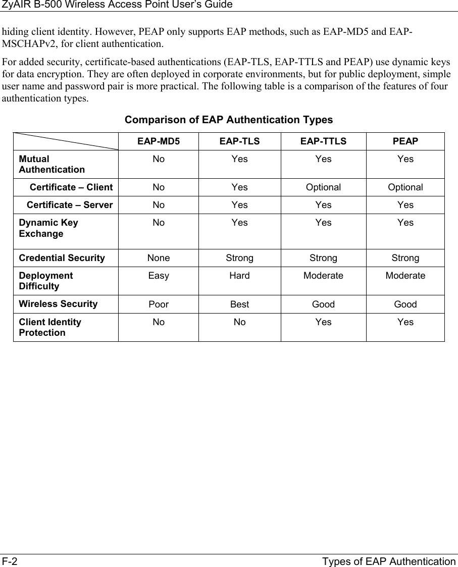
![ZyAIR B-500 Wireless Access Point User’s Guide 15-4 System Security Figure 15-5 Menu 23.4 System Security : IEEE802.1x The following table describes the fields in this menu. Table 15-2 Menu 23.4 System Security : IEEE802.1x FIELD DESCRIPTION Wireless Port Control Press [SPACE BAR] and select a security mode for the wireless LAN access. Select No Authentication Required to allow any wireless stations access to your wired network without entering usernames and passwords. This is the default setting. Selecting Authentication Required means wireless stations have to enter usernames and passwords before access to the wired network is allowed. Select No Access Allowed to block all wireless stations access to the wired network. ReAuthentica-tion Timer (in seconds) Specify how often a wireless station has to re-enter username and password to stay connected to the wired network. This field is activated only when you select Authentication Required in the Wireless Port Control field. Enter a time interval between 10 and 9999 (in seconds). The default time interval is 1800 seconds (or 30 minutes). Idle Timeout The ZyAIR automatically disconnects a wireless station from the wired network after a period of inactivity. The wireless station needs to enter the username and password again before access to the wired network is allowed. This field is activated only when you select Authentication Required in the Wireless Port Control field. The default time interval is 3600 seconds (or 1 hour). Menu 23.4 - System Security - IEEE802.1X Wireless Port Control= Authentication Required ReAuthentication Timer (in second)= 1800 Idle Timeout (in second)= 3600 Authentication Databases= Local User Database Only Press ENTER to Confirm or ESC to Cancel:](https://usermanual.wiki/ZyXEL-Communications/B500.Users-Manual-2/User-Guide-378793-Page-28.png)
![ZyAIR B-500 Wireless Access Point User’s Guide System Security 15-5 Table 15-2 Menu 23.4 System Security : IEEE802.1x FIELD DESCRIPTION Authentication Databases This field is activated only when you select Authentication Required in the Wireless Port Control field. The authentication database contains wireless station login information. The local user database is the built-in database on the ZyAIR. The RADIUS is an external server. Use this field to decide which database the ZyAIR should use (first) to authenticate a wireless station. Before you specify the priority, make sure you have set up the corresponding database correctly first. Select Local User Database Only to have the ZyAIR just check the built-in user database on the ZyAIR for a wireless station's username and password. Select RADIUS Only to have the ZyAIR just check the user database on the specified RADIUS server for a wireless station's username and password. Select Local first, then RADIUS to have the ZyAIR first check the user database on the ZyAIR for a wireless station's username and password. If the user name is not found, the ZyAIR then checks the user database on the specified RADIUS server. Select RADIUS first, then Local to have the ZyAIR first check the user database on the specified RADIUS server for a wireless station's username and password. If the ZyAIR cannot reach the RADIUS server, the ZyAIR then checks the local user database on the ZyAIR. When the user name is not found or password does not match in the RADIUS server, the ZyAIR will not check the local user database and the authentication fails. When you have completed this menu, press [ENTER] at the prompt “Press ENTER to confirm or ESC to cancel” to save your configuration or press [ESC] to cancel and go back to the previous screen. Once you enable user authentication, you need to specify an external RADIUS server or create local user accounts on the ZyAIR for authentication.](https://usermanual.wiki/ZyXEL-Communications/B500.Users-Manual-2/User-Guide-378793-Page-29.png)
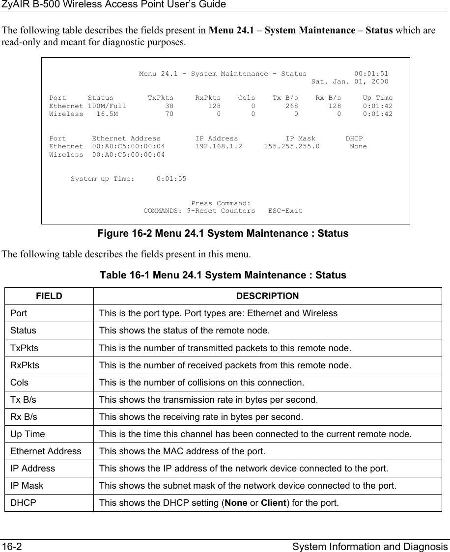
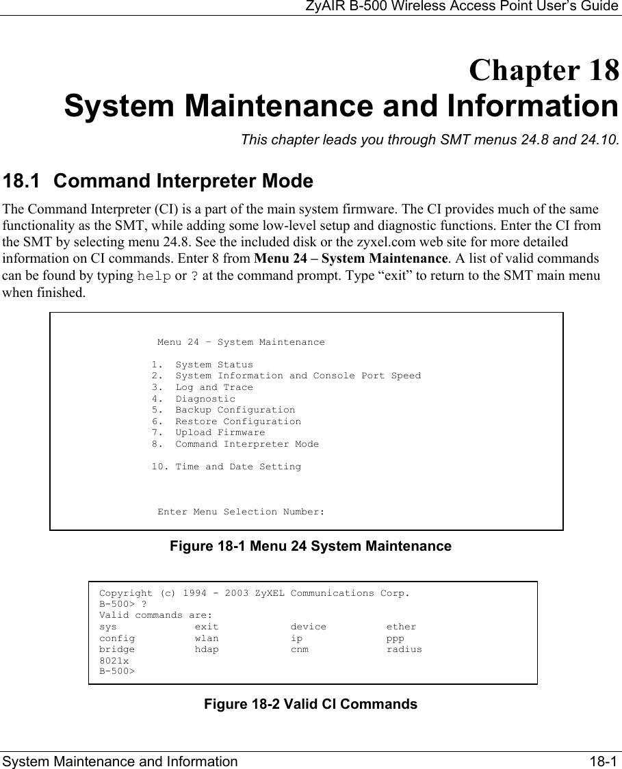
![ZyAIR B-500 Wireless Access Point User’s Guide System Information and Diagnosis 16-1 Chapter 16 System Information and Diagnosis This chapter covers the information and diagnostic tools in SMT menus 24.1 to 24.4. 16.1 Overview These tools include updates on system status, port status, log and trace capabilities and upgrades for the system software. This chapter describes how to use these tools in detail. Type 24 in the main menu and press [ENTER] to open Menu 24 – System Maintenance, as shown in the following figure. Figure 16-1 Menu 24 System Maintenance 16.2 System Status The first selection, System Status gives you information on the status and statistics of the ports, as shown next. System Status is a tool that can be used to monitor your ZyAIR. Specifically, it gives you information on your Ethernet and Wireless LAN status, number of packets sent and received. To get to System Status, type 24 to go to Menu 24 – System Maintenance. From this menu, type 1. System Status. There are two commands in Menu 24.1 – System Maintenance – Status. Entering 9 resets the counters; pressing [ESC] takes you back to the previous screen. Menu 24 – System Maintenance 1. System Status 2. System Information and Console Port Speed 3. Log and Trace 4. Diagnostic 5. Backup Configuration 6. Restore Configuration 7. Upload Firmware 8. Command Interpreter Mode 10. Time and Date Setting Enter Menu Selection Number:](https://usermanual.wiki/ZyXEL-Communications/B500.Users-Manual-2/User-Guide-378793-Page-31.png)
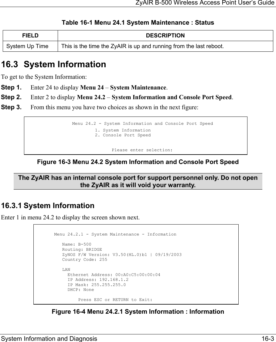
![ZyAIR B-500 Wireless Access Point User’s Guide 16-4 System Information and Diagnosis The following table describes the fields in this menu. Table 16-2 Menu 24.2.1 System Maintenance : Information FIELD DESCRIPTION Name Displays the system name of your ZyAIR. This information can be changed in Menu 1 – General Setup. Routing Refers to the routing protocol used. ZyNOS F/W Version Refers to the ZyNOS (ZyXEL Network Operating System) system firmware version. ZyNOS is a registered trademark of ZyXEL Communications Corporation. Country Code Refers to the country code of the firmware. LAN Ethernet Address Refers to the Ethernet MAC (Media Access Control) of your ZyAIR. IP Address This is the IP address of the ZyAIR in dotted decimal notation. IP Mask This shows the subnet mask of the ZyAIR. DHCP This field shows the DHCP setting of the ZyAIR. When you have completed this menu, press [ENTER] at the prompt “Press ENTER to confirm or ESC to cancel” to save your configuration or press [ESC] to cancel and go back to the previous screen. 16.3.2 Console Port Speed You can set up different port speeds for the console port through Menu 24.2.2 – System Maintenance – Console Port Speed. Your ZyAIR supports 9600 (default), 19200, 38400, 57600 and 115200 bps console port speeds. Press [SPACE BAR] and then [ENTER] to select the desired speed in menu 24.2.2, as shown in the following figure. Figure 16-5 Menu 24.2.2 System Maintenance : Change Console Port Speed After you changed the console port speed on your ZyAIR, you must also make the same change to the console port speed parameter of your communication software. Menu 24.2.2 – System Maintenance – Change Console Port Speed Console Port Speed: 9600 Press ENTER to Confirm or ESC to Cancel:](https://usermanual.wiki/ZyXEL-Communications/B500.Users-Manual-2/User-Guide-378793-Page-34.png)
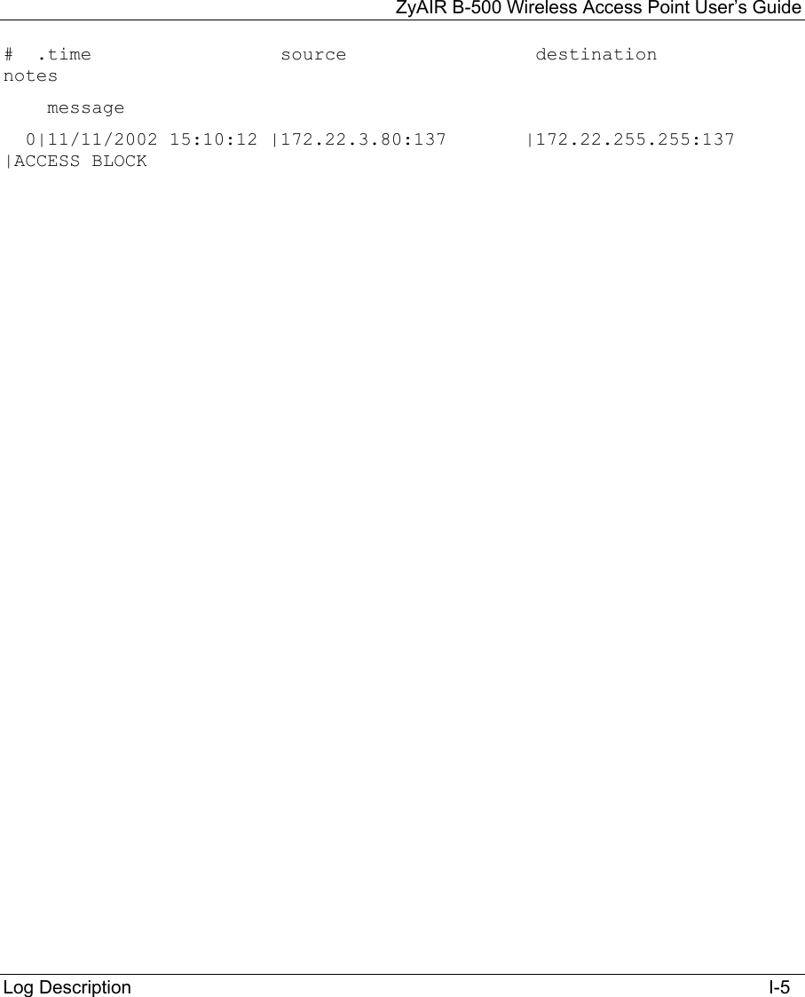
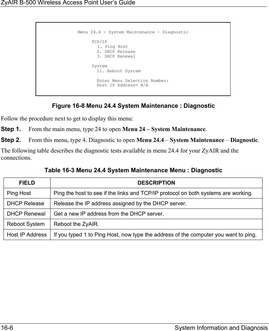
![ZyAIR B-500 Wireless Access Point User’s Guide System Information and Diagnosis 16-5 16.4 Log and Trace Your ZyAIR provides the error logs and trace records that are stored locally. 16.4.1 Viewing Error Log The first place you should look for clues when something goes wrong is the error log. Follow the procedures to view the local error/trace log: Step 1. Type 24 in the main menu to display Menu 24 – System Maintenance. Step 2. From menu 24, type 3 to display Menu 24.3 – System Maintenance – Log and Trace. Figure 16-6 Menu 24.3 System Maintenance : Log and Trace Step 3. Enter 1 from Menu 24.3 – System Maintenance – Log and Trace and press [ENTER] twice to display the error log in the system. After the ZyAIR finishes displaying the error log, you will have the option to clear it. Samples of typical error and information messages are presented in the next figure. Figure 16-7 Sample Error and Information Messages 16.5 Diagnostic The diagnostic facility allows you to test the different aspects of your ZyAIR to determine if it is working properly. Menu 24.4 allows you to choose among various types of diagnostic tests to evaluate your system, as shown in the following figure. Menu 24.3 - System Maintenance - Log and Trace 1. View Error Log Please enter selection: 13 Sat Jan 1 00:00:00 2000 PP0d INFO LAN promiscuous mode <1> 14 Sat Jan 1 00:00:00 2000 PINI INFO Last errorlog repeat 1 Times 15 Sat Jan 1 00:00:00 2000 PINI INFO main: init completed 16 Sat Jan 1 00:00:02 2000 PP05 -WARN SNMP TRAP 3: link up 17 Sat Jan 1 00:00:02 2000 PP13 INFO sending request to NTP server(6) 20 Sat Jan 1 00:00:30 2000 PSSV -WARN SNMP TRAP 0: cold start Clear Error Log (y/n):](https://usermanual.wiki/ZyXEL-Communications/B500.Users-Manual-2/User-Guide-378793-Page-35.png)
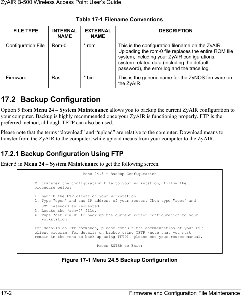
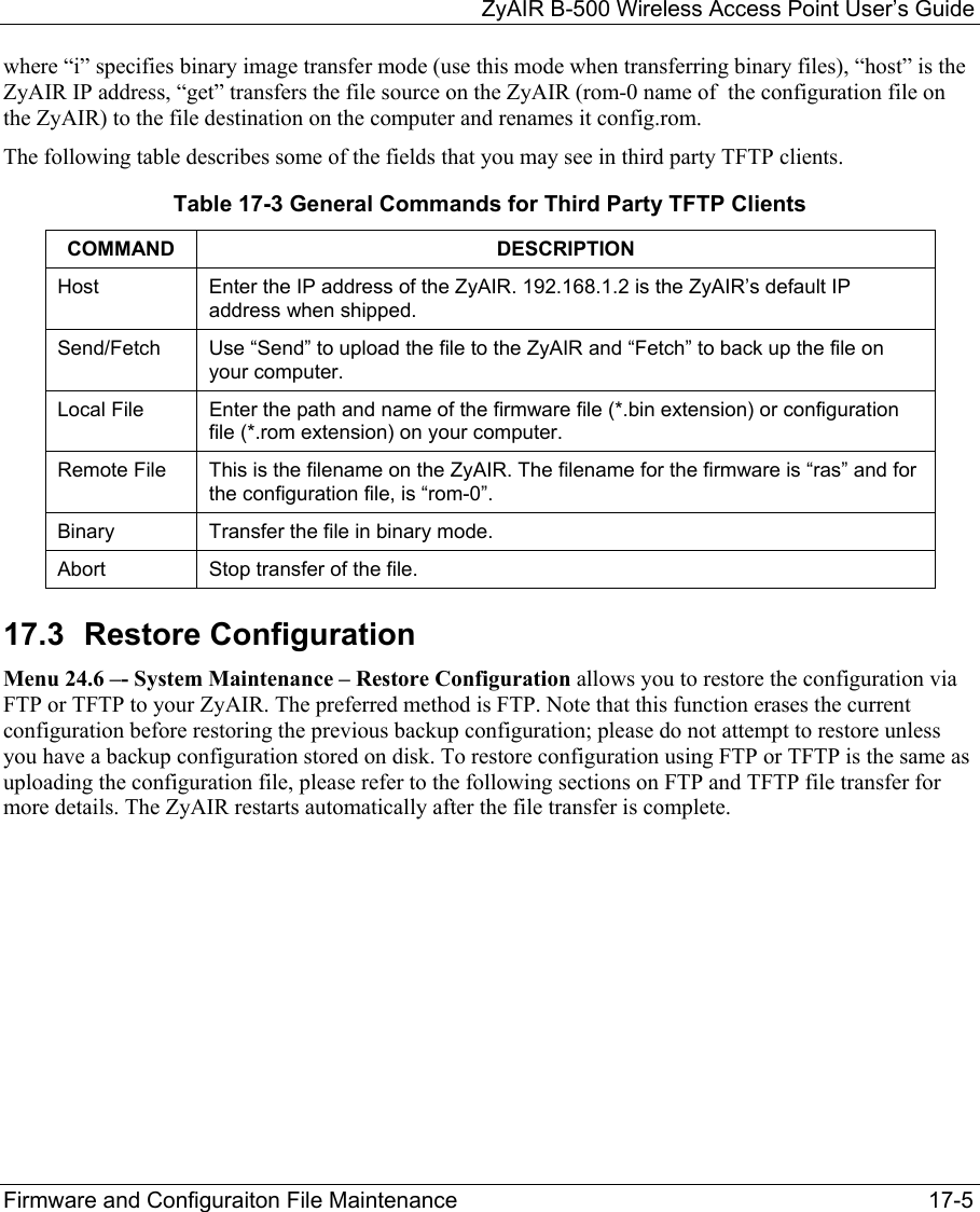
![ZyAIR B-500 Wireless Access Point User’s Guide Firmware and Configuraiton File Maintenance 17-1 Chapter 17 Firmware and Configuration File Maintenance This chapter tells you how to backup and restore your configuration file as well as upload new firmware and configuration files using the SMT screens. 17.1 Filename Conventions The configuration file (often called the romfile or rom-0) contains the factory default settings in the menus such as password and TCP/IP Setup, etc. It arrives from ZyXEL with a rom filename extension. Once you have customized the ZyAIR's settings, they can be saved back to your computer under a filename of your choosing. ZyNOS (ZyXEL Network Operating System sometimes referred to as the “ras” file) is the system firmware and has a “bin” filename extension. With many FTP and TFTP clients, the filenames are similar to those seen next. ftp> put firmware.bin ras This is a sample FTP session showing the transfer of the computer file " firmware.bin" to the ZyAIR. ftp> get rom-0 config.cfg This is a sample FTP session saving the current configuration to the computer file config.cfg. If your [T]FTP client does not allow you to have a destination filename different than the source, you will need to rename them as the ZyAIR only recognizes “rom-0” and “ras”. Be sure you keep unaltered copies of both files for later use. The following table is a summary. Please note that the internal filename refers to the filename on the ZyAIR and the external filename refers to the filename not on the ZyAIR, that is, on your computer, local network or FTP site and so the name (but not the extension) will vary. After uploading new firmware see the ZyNOS F/W Version field in Menu 24.2.1 – System Maintenance – Information to confirm that you have uploaded the correct firmware version.](https://usermanual.wiki/ZyXEL-Communications/B500.Users-Manual-2/User-Guide-378793-Page-37.png)
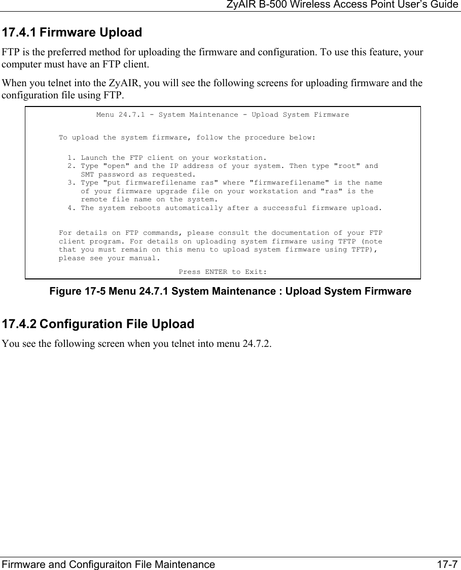
![ZyAIR B-500 Wireless Access Point User’s Guide Firmware and Configuraiton File Maintenance 17-3 17.2.2 Using the FTP command from the DOS Prompt Step 1. Launch the FTP client on your computer. Step 2. Enter “open” and the IP address of your ZyAIR. Step 3. Press [ENTER] when prompted for a username. Step 4. Enter “root” and your SMT password as requested. The default is 1234. Step 5. Enter “bin” to set transfer mode to binary. Step 6. Use “get” to transfer files from the ZyAIR to the computer, for example, “get rom-0 config.rom” transfers the configuration file on the ZyAIR to your computer and renames it “config.rom”. See earlier in this chapter for more information on filename conventions. Step 7. Enter “quit” to exit the FTP prompt. Figure 17-2 FTP Session Example The following table describes some of the commands that you may see in third party FTP clients. Table 17-2 General Commands for Third Party FTP Clients COMMAND DESCRIPTION Host Address Enter the address of the host server. Login Type Anonymous. This is when a user I.D. and password is automatically supplied to the server for anonymous access. Anonymous logins will work only if your ISP or service administrator has enabled this option. Normal. The server requires a unique User ID and Password to login. Transfer Type Transfer files in either ASCII (plain text format) or in binary mode. 331 Enter PASS command Password: 230 Logged in ftp> bin 200 Type I OK ftp> get rom-0 zyxel.rom 200 Port command okay 150 Opening data connection for STOR ras 226 File received OK ftp: 327680 bytes sent in 1.10Seconds 297.89Kbytes/sec. ftp> quit](https://usermanual.wiki/ZyXEL-Communications/B500.Users-Manual-2/User-Guide-378793-Page-39.png)
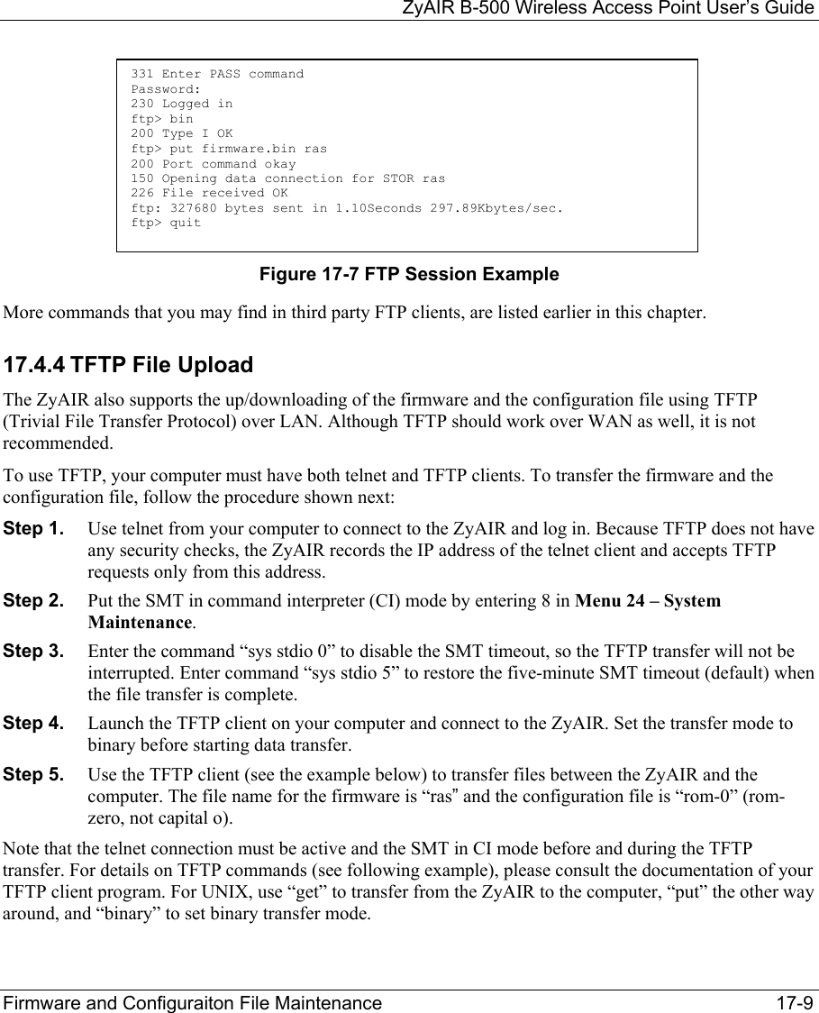
![ZyAIR B-500 Wireless Access Point User’s Guide 17-4 Firmware and Configuraiton File Maintenance Table 17-2 General Commands for Third Party FTP Clients COMMAND DESCRIPTION Initial Remote Directory Specify the default remote directory (path). Initial Local Directory Specify the default local directory (path). 17.2.3 Backup Configuration Using TFTP The ZyAIR supports the up/downloading of the firmware and the configuration file using TFTP (Trivial File Transfer Protocol) over LAN. Although TFTP should work over WAN as well, it is not recommended. To use TFTP, your computer must have both telnet and TFTP clients. To backup the configuration file, follow the procedure shown next: Step 1. Use telnet from your computer to connect to the ZyAIR and log in. Because TFTP does not have any security checks, the ZyAIR records the IP address of the telnet client and accepts TFTP requests only from this address. Step 2. Put the SMT in command interpreter (CI) mode by entering 8 in Menu 24 – System Maintenance. Step 3. Enter command “sys stdio 0” to disable the SMT timeout, so the TFTP transfer will not be interrupted. Enter command “sys stdio 5” to restore the five-minute SMT timeout (default) when the file transfer is complete. Step 4. Launch the TFTP client on your computer and connect to the ZyAIR. Set the transfer mode to binary before starting data transfer. Step 5. Use the TFTP client (see the example below) to transfer files between the ZyAIR and the computer. The file name for the configuration file is rom-0 (rom-zero, not capital o). Note that the telnet connection must be active and the SMT in CI mode before and during the TFTP transfer. For details on TFTP commands (see following example), please consult the documentation of your TFTP client program. For UNIX, use “get” to transfer from the ZyAIR to the computer and “binary” to set binary transfer mode. 17.2.4 Example: TFTP Command The following is an example TFTP command: TFTP [-i] host get rom-0 config.rom](https://usermanual.wiki/ZyXEL-Communications/B500.Users-Manual-2/User-Guide-378793-Page-40.png)
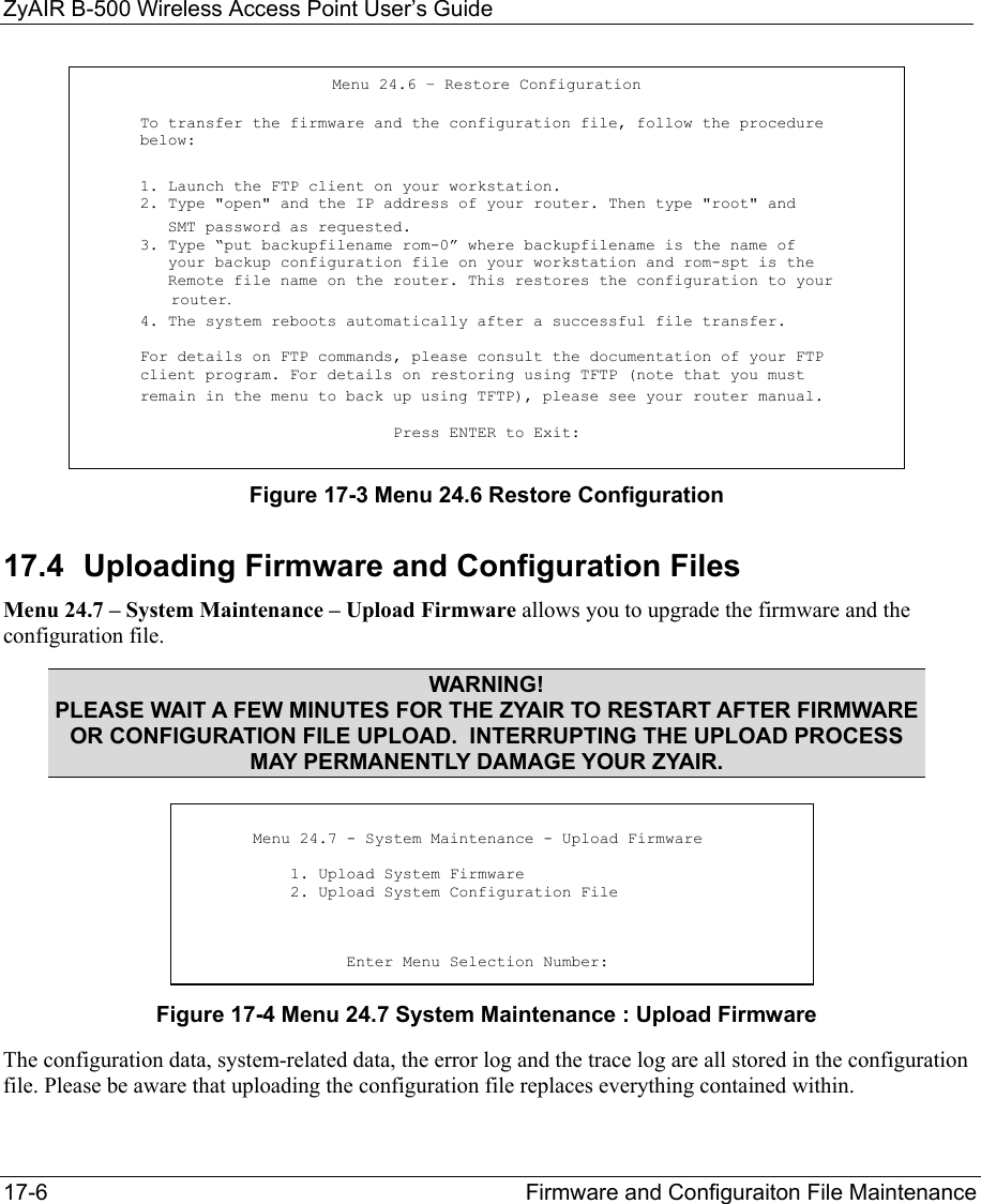
![ZyAIR B-500 Wireless Access Point User’s Guide 17-8 Firmware and Configuraiton File Maintenance Figure 17-6 Menu 24.7.2 System Maintenance : Upload System Configuration File To transfer the firmware and the configuration file, follow these examples: 17.4.3 Using the FTP command from the DOS Prompt Example Step 1. Launch the FTP client on your computer. Step 2. Enter “open” and the IP address of your ZyAIR. Step 3. Press [ENTER] when prompted for a username. Step 4. Enter “root” and your SMT password as requested. The default is 1234. Step 5. Enter “bin” to set transfer mode to binary. Step 6. Use “put” to transfer files from the computer to the ZyAIR, e.g., put firmware.bin ras transfers the firmware on your computer (firmware.bin) to the ZyAIR and renames it “ras”. Similarly “put config.rom rom-0” transfers the configuration file on your computer (config.rom) to the ZyAIR and renames it “rom-0”. Likewise “get rom-0 config.rom” transfers the configuration file on the ZyAIR to your computer and renames it “config.rom.” See earlier in this chapter for more information on filename conventions. Step 7. Enter “quit” to exit the FTP prompt. Menu 24.7.2 - System Maintenance - Upload System Configuration File To upload the system configuration file, follow the procedure below: 1. Launch the FTP client on your workstation. 2. Type "open" and the IP address of your system. Then type "root" and SMT password as requested. 3. Type "put configurationfilename rom-0" where "configurationfilename" is the name of your system configuration file on your workstation, which will be transferred to the "rom-0" file on the system. 4. The system reboots automatically after the upload system configuration file process is complete. For details on FTP commands, please consult the documentation of your FTP client program. For details on uploading system firmware using TFTP (note that you must remain on this menu to upload system firmware using TFTP), please see your manual. Press ENTER to Exit:](https://usermanual.wiki/ZyXEL-Communications/B500.Users-Manual-2/User-Guide-378793-Page-44.png)
![ZyAIR B-500 Wireless Access Point User’s Guide 17-10 Firmware and Configuraiton File Maintenance 17.4.5 Example: TFTP Command The following is an example TFTP command: TFTP [-i] host put firmware.bin ras where “i” specifies binary image transfer mode (use this mode when transferring binary files), “host” is the ZyAIR’s IP address, “put” transfers the file source on the computer (firmware.bin – name of the firmware on the computer) to the file destination on the remote host (ras - name of the firmware on the ZyAIR). Commands that you may see in third party TFTP clients are listed earlier in this chapter.](https://usermanual.wiki/ZyXEL-Communications/B500.Users-Manual-2/User-Guide-378793-Page-46.png)
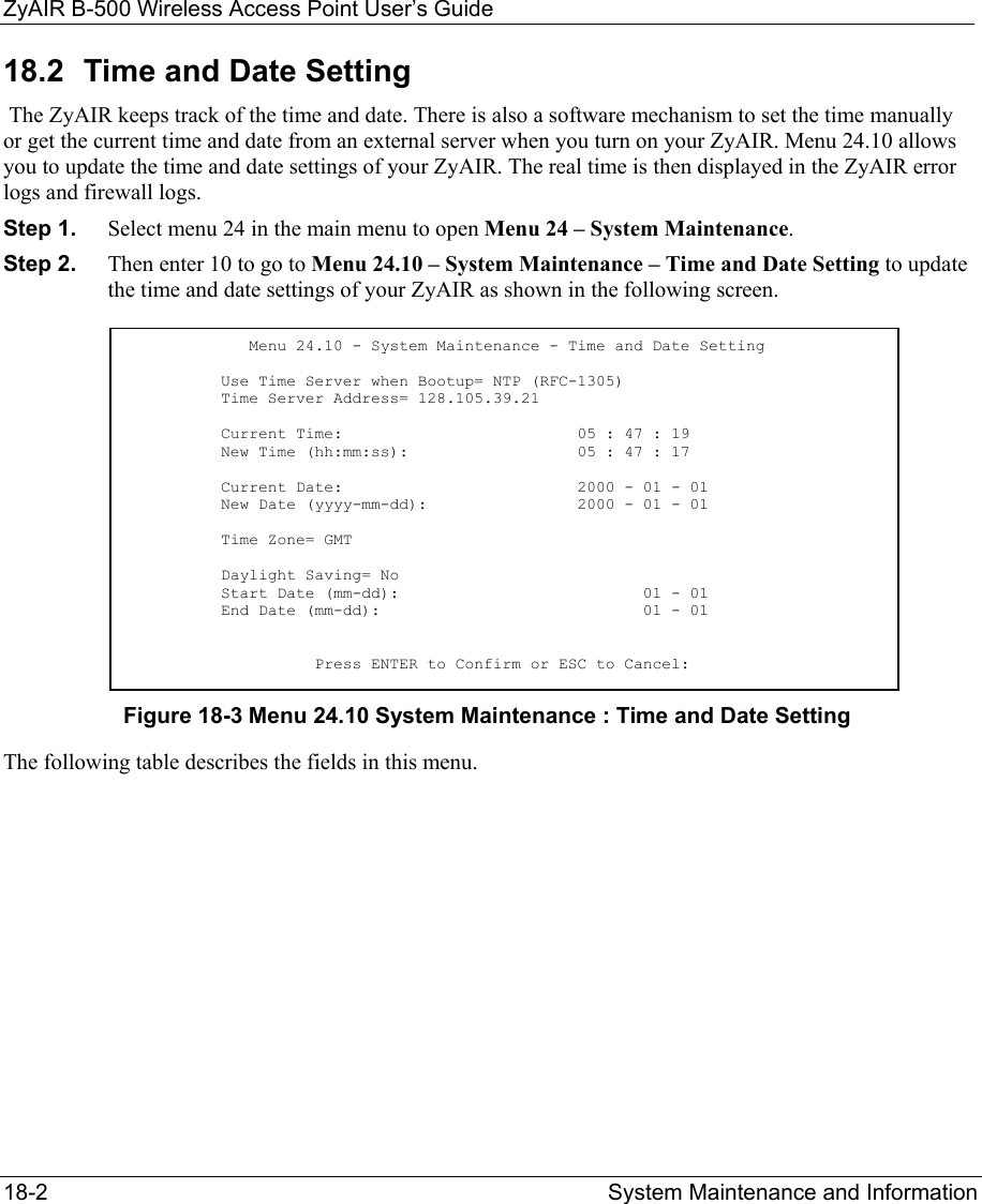
![ZyAIR B-500 Wireless Access Point User’s Guide System Maintenance and Information 18-3 Table 18-1 Menu 24.10 System Maintenance : Time and Date Setting FIELD DESCRIPTION Use Time Server when Bootup Enter the time service protocol that your time server sends when you turn on the ZyAIR. Not all time servers support all protocols, so you may have to check with your ISP/network administrator or use trial and error to find a protocol that works. The main differences between them are the format. Daytime (RFC 867) format is day/month/year/time zone of the server. Time (RFC-868) format displays a 4-byte integer giving the total number of seconds since 1970/1/1 at 0:0:0. NTP (RFC-1305) is similar to Time (RFC-868). None. The default, enter the time manually. Time Server Address Enter the IP address or domain name of your time server. Check with your ISP/network administrator if you are unsure of this information. Current Time This field displays an updated time only when you reenter this menu. New Time Enter the new time in hour, minute and second format. Current Date This field displays an updated date only when you re-enter this menu. New Date Enter the new date in year, month and day format. Time Zone Press [SPACE BAR] and then [ENTER] to set the time difference between your time zone and Greenwich Mean Time (GMT). Daylight Saving If you use daylight savings time, then choose Yes. Start Date If using daylight savings time, enter the month and day that it starts on. End Date If using daylight savings time, enter the month and day that it ends on Once you have filled in this menu, press [ENTER] at the message “Press ENTER to Confirm or ESC to Cancel“ to save your configuration, or press [ESC] to cancel. 18.2.1 Resetting the Time The ZyAIR resets the time in three instances: i. On leaving menu 24.10 after making changes. ii. When the ZyAIR starts up, if there is a time server configured in menu 24.10. iii. 24-hour intervals after starting.](https://usermanual.wiki/ZyXEL-Communications/B500.Users-Manual-2/User-Guide-378793-Page-49.png)
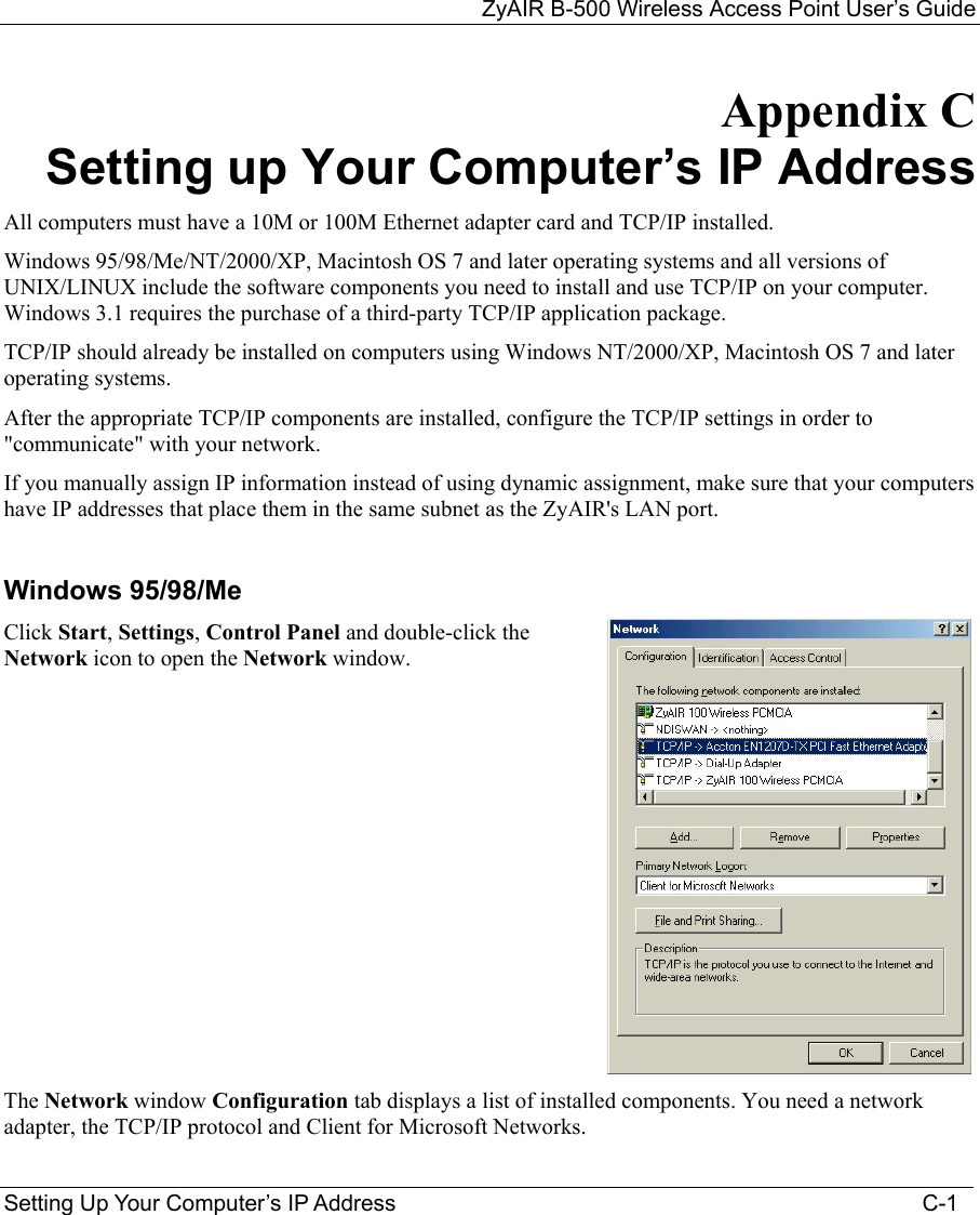
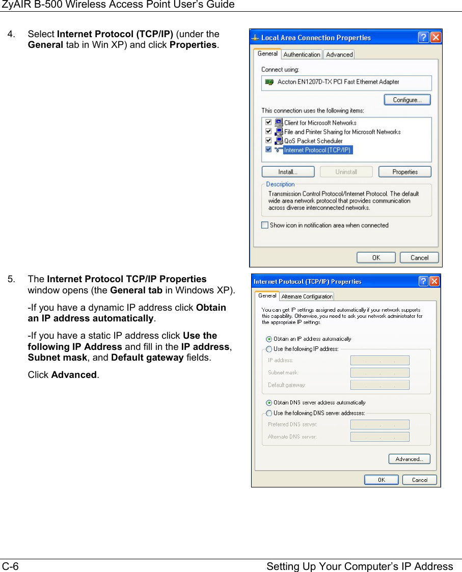
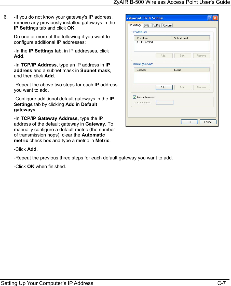
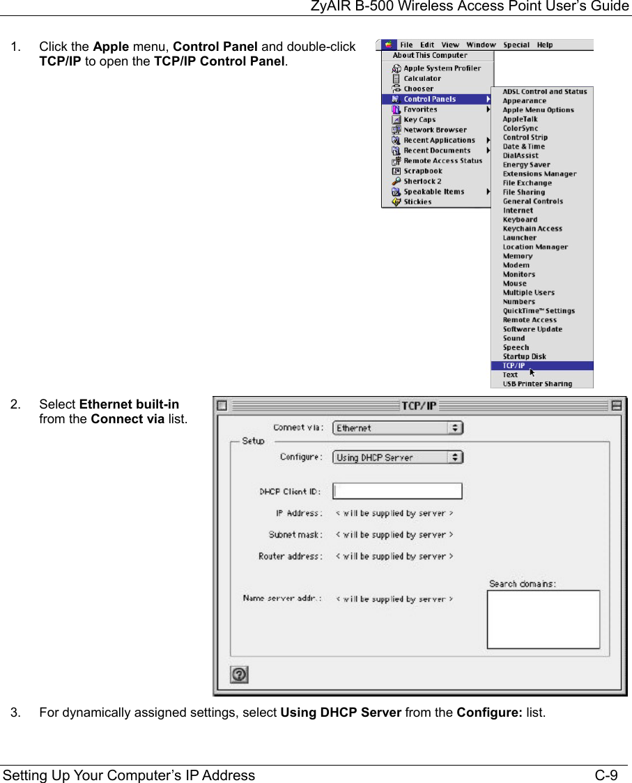
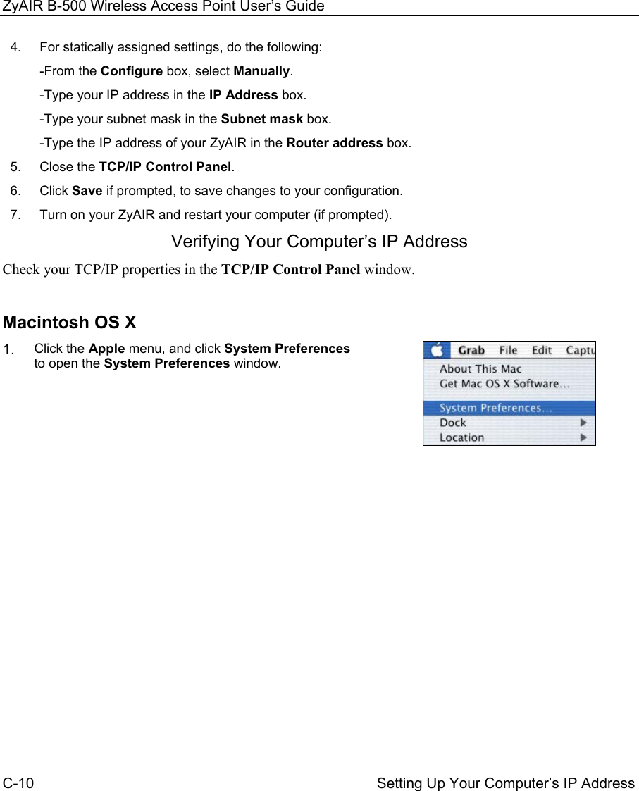
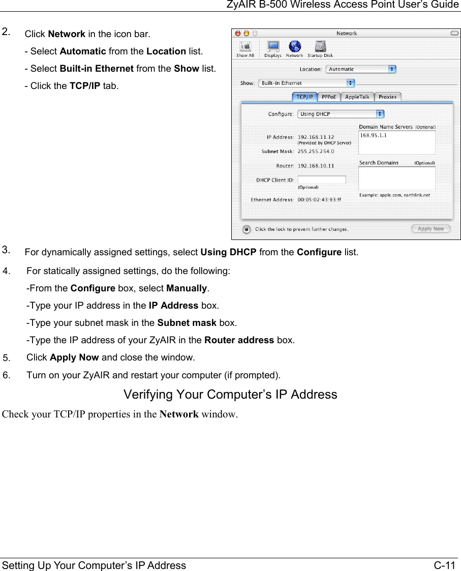
![ZyAIR B-500 Wireless Access Point User’s Guide C-8 Setting Up Your Computer’s IP Address 7. In the Internet Protocol TCP/IP Properties window (the General tab in Windows XP): -Click Obtain DNS server address automatically if you do not know your DNS server IP address(es). -If you know your DNS server IP address(es), click Use the following DNS server addresses, and type them in the Preferred DNS server and Alternate DNS server fields. If you have previously configured DNS servers, click Advanced and then the DNS tab to order them. 8. Click OK to close the Internet Protocol (TCP/IP) Properties window. 9. Click OK to close the Local Area Connection Properties window. 10. Turn on your ZyAIR and restart your computer (if prompted). Verifying Your Computer’s IP Address 1. Click Start, All Programs, Accessories and then Command Prompt. 2. In the Command Prompt window, type "ipconfig" and then press [ENTER]. You can also open Network Connections, right-click a network connection, click Status and then click the Support tab. Macintosh OS 8/9](https://usermanual.wiki/ZyXEL-Communications/B500.Users-Manual-2/User-Guide-378793-Page-65.png)
![ZyAIR B-500 Wireless Access Point User’s Guide Command Interpreter H-1 Appendix H Command Interpreter The following describes how to use the command interpreter. Enter 24 in the main menu to bring up the system maintenance menu. Enter 8 to go to Menu 24.8 - Command Interpreter Mode. See the included disk or www.zyxel.com for more detailed information on these commands. Use of undocumented commands or misconfiguration can damage the unit and possibly render it unusable. Command Syntax The command keywords are in courier new font. Enter the command keywords exactly as shown, do not abbreviate. The required fields in a command are enclosed in angle brackets <>. The optional fields in a command are enclosed in square brackets []. The |symbol means “or”. For example, sys filter netbios config <type> <on|off> means that you must specify the type of netbios filter and whether to turn it on or off. Command Usage A list of valid commands can be found by typing help or ? at the command prompt. Always type the full command. Type exit to return to the SMT main menu when finished.](https://usermanual.wiki/ZyXEL-Communications/B500.Users-Manual-2/User-Guide-378793-Page-86.png)
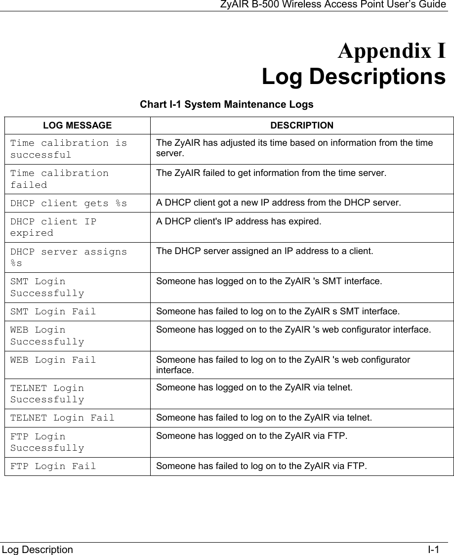
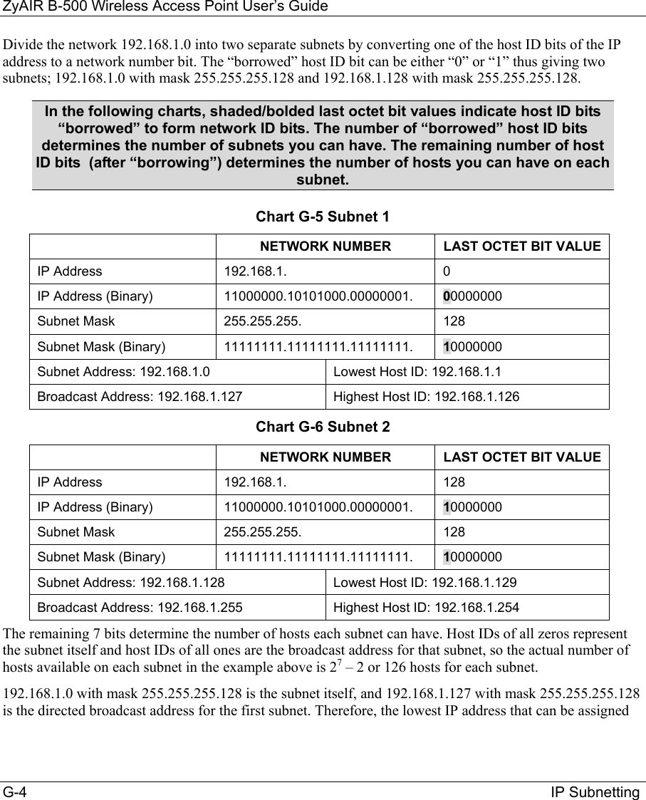
![ZyAIR B-500 Wireless Access Point User’s Guide I-4 Log Descriptions Chart I-4 Log Categories and Available Settings LOG CATEGORIES AVAILABLE PARAMETERS 8021x 0, 1 access 0, 1, 2, 3 error 0, 1, 2, 3 icmp 0, 1 mten 0, 1 packetfilter 0, 1 remote 0, 1 tcpreset 0, 1 Use 0 to not record logs for that category, 1 to record only logs for that category, 2 to record only alerts for that category, and 3 to record both logs and alerts for that category. Use the sys logs save command to store the settings in the ZyAIR (you must do this in order to record logs). Displaying Logs Use the sys logs display command to show all of the logs in the ZyAIR’s log. Use the sys logs category display command to show the log settings for all of the log categories. Use the sys logs display [log category] command to show the logs in an individual ZyAIR log category. Use the sys logs clear command to erase all of the ZyAIR’s logs. Log Command Example This example shows how to set the ZyAIR to record the error logs and alerts and then view the results. ras> sys logs load ras> sys logs category error 3 ras> sys logs save ras> sys logs display access](https://usermanual.wiki/ZyXEL-Communications/B500.Users-Manual-2/User-Guide-378793-Page-91.png)