ZyXEL Communications B500 Wireless LAN Access Point User Manual P650H 17 ADSL Router User s Guide
ZyXEL Communications Corporation Wireless LAN Access Point P650H 17 ADSL Router User s Guide
Contents
- 1. Users Manual 1
- 2. Users Manual 2
Users Manual 2

SMT Configuration
V
Part V:
SMT CONFIGURATION
This part contains SMT (System Management Terminal) configuration and background
information for features only configurable by SMT.
See the web configurator parts of this guide for background information on
features configurable by web configurator and SMT.
BETA DRAFT

ZyAIR B-500 Wireless Access Point User’s Guide
Introducing the SMT 10-1
Chapter 10
Introducing the SMT
This chapter describes how to access the SMT and provides an overview of its menus.
10.1 Connect to your ZyAIR Using Telnet
The following procedure details how to telnet into your ZyAIR.
Step 1. In Windows, click Start (usually in the bottom left corner), Run and then type “telnet
192.168.1.2” (the default IP address) and click OK.
Step 2. For your first login, enter the default password “1234”. As you type the password, the screen
displays an asterisk “*” for each character you type.
Figure 10-1 Login Screen
Step 3. After entering the password you will see the main menu.
Please note that if there is no activity for longer than five minutes (default timeout period) after you log in,
your ZyAIR will automatically log you out. You will then have to telnet into the ZyAIR again. You can use
the web configurator or the CI commands to change the inactivity time out period.
10.2 Changing the System Password
Change the ZyAIR default password by following the steps shown next.
Step 1. From the main menu, enter 23 to display Menu 23 – System Security.
Step 2. Enter 1 to display Menu 23.1 – System Security – Change Password as shown next.
Step 3. Type your existing system password in the Old Password field, and press [ENTER].
Password : ****

ZyAIR B-500 Wireless Access Point User’s Guide
10-2 Introducing the SMT
Figure 10-2 Menu 23.1 System Security : Change Password
Step 4. Type your new system password in the New Password field (up to 30 characters), and press
[ENTER].
Step 5. Re-type your new system password in the Retype to confirm field for confirmation and press
[ENTER].
Note that as you type a password, the screen displays an asterisk “*” for each character you type.
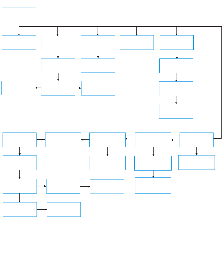
10.3 ZyAIR SMT Menu Overview Example
The following figure gives you an example overview of the various SMT menu screens for your ZyAIR.
Menu 23.1 – System Security – Change Password
Old Password= ****
New Password= ?
Retype to confirm= ?
Enter here to CONFIRM or ESC to CANCEL:
ZyAIR B-500 Wireless Access Point User’s Guide
Introducing the SMT 10-3
ZyAIR B-500
Main Menu
Menu 1
General Setup
Menu 3
LAN Setup
Menu 3.5
Wireless LAN
Setup
Menu 3.2
TCP/IP Setup
Menu 3.5.1
WLAN MAC
Address Filter
Menu 3.5.2
Roaming
Configuration
Menu 14
Dial-in User Setup
Menu14.1
Edit Dial-in User
Menu 22
SNMP
Configuration
Menu 23
System Security
Menu 23.1
System Security-
Change Password
Menu 23.2
System Security-
RADIUS Server
Menu 23.4
System Security-
IEEE802.1x
Menu 24
System
Maintenance
Menu 24.1
System Maintenance
- Status
Menu 24.2
System Information and
Console Port Speed
Menu 24.3
System Maintenance
- Log and Trace
Menu 24.5
Backup
Configuration
Menu 24.6
Restore
Configuration
Menu 24.2.2
System Maintenance
- Change Console Port
Speed
Menu 24.3.1
System Maintenance
- View Error Log
Menu 24.7.2
Upload System
Configuration File
Menu 24.2.1
System Maintenance
- Information
Menu 24.7
Upload Firmware
Menu 24.7.1
Upload System
Firmware
Menu 24.8
Command
Interpreter Mode
Menu 24.10
Time and Date
Setting
Menu 24.4
System Maintenance
- Diagnostic
Figure 10-3 ZyAIR B-500 SMT Menu Overview Example

ZyAIR B-500 Wireless Access Point User’s Guide
10-4 Introducing the SMT
10.4 Navigating the SMT Interface
The SMT (System Management Terminal) is the interface that you use to configure your ZyAIR.
Several operations that you should be familiar with before you attempt to modify the configuration are
listed in the table below.
Table 10-1 Main Menu Commands
OPERATION KEYSTROKE DESCRIPTION
Move down to
another menu
[ENTER] To move forward to a submenu, type in the number of the desired
submenu and press [ENTER].
Move up to a
previous menu
[ESC] Press [ESC] to move back to the previous menu.
Move to a “hidden”
menu
Press [SPACE
BAR] to change No
to Yes then press
[ENTER].
Fields beginning with “Edit” lead to hidden menus and have a
default setting of No. Press [SPACE BAR] once to change No to
Yes, then press [ENTER] to go to the “hidden” menu.
Move the cursor [ENTER] or
[UP]/[DOWN] arrow
keys.
Within a menu, press [ENTER] to move to the next field. You can
also use the [UP]/[DOWN] arrow keys to move to the previous
and the next field, respectively.
Entering
information
Type in or press
[SPACE BAR], then
press [ENTER].
You need to fill in two types of fields. The first requires you to type
in the appropriate information. The second allows you to cycle
through the available choices by pressing [SPACE BAR].
Required fields <?> or ChangeMe All fields with the symbol <?> must be filled in order to be able to
save the new configuration.
All fields with ChangeMe must not be left blank in order to be
able to save the new configuration.
N/A fields <N/A> Some of the fields in the SMT will show a <N/A>. This symbol
refers to an option that is Not Applicable.
Save your
configuration
[ENTER] Save your configuration by pressing [ENTER] at the message
“Press ENTER to confirm or ESC to cancel”. Saving the data on
the screen will take you, in most cases to the previous menu.
Exit the SMT Type 99, then press
[ENTER].
Type 99 at the main menu prompt and press [ENTER] to exit the
SMT interface.
After you enter the password, the SMT displays the main menu, as shown next.

ZyAIR B-500 Wireless Access Point User’s Guide
Introducing the SMT 10-5
Figure 10-4 ZyAIR B-500 SMT Main Menu
10.4.1 System Management Terminal Interface Summary
Table 10-2 Main Menu Summary
# MENU TITLE DESCRIPTION
1 General Setup Use this menu to set up your general information.
3 LAN Setup Use this menu to set up your LAN and WLAN connection.
14 Dial-in User Setup Use this menu to set up local user profiles on the ZyAIR.
22 SNMP Configuration Use this menu to set up SNMP related parameters.
23 System Security Use this menu to change your password and enable network user
authentication.
24 System Maintenance This menu provides system status, diagnostics, software upload, etc.
99 Exit Use this to exit from SMT and return to a blank screen.
Copyright (c) 1994 - 2003 ZyXEL Communications Corp.
ZyAIR B-500 Main Menu
Getting Started Advanced Management
1. General Setup 22. SNMP Configuration
3. LAN Setup 23. System Security
24. System Maintenance
Advanced Applications
14. Dial-in User Setup
99. Exit
Enter Menu Selection Number:

ZyAIR B-500 Wireless Access Point User’s Guide
General Setup 11-1
Chapter 11
General Setup
The chapter shows you the information on general setup.
11.1 General Setup
Menu 1 – General Setup contains administrative and system-related information (shown next). The
System Name field is for identification purposes. It is recommended you type your computer's "Computer
name".
The Domain Name entry is what is propagated to the DHCP clients on the LAN. This is not a required
field. Leave this field blank or enter the domain name here if you know it.
11.1.1 Procedure To Configure Menu 1
Step 1. Enter 1 in the Main Menu to open Menu 1 – General Setup as shown next.
Figure 11-1 Menu 1 General Setup
Step 2. Fill in the required fields. Refer to the following table for more information about these fields.
Menu 1 - General Setup
System Name= B-500
Domain Name=
First System DNS Server= From DHCP
IP Address= N/A
Second System DNS Server= None
IP Address= N/A
Third System DNS Server= None
IP Address= N/A
Press ENTER to Confirm or ESC to Cancel:

ZyAIR B-500 Wireless Access Point User’s Guide
11-2 General Setup
Table 11-1 Menu 1 General Setup
FIELD DESCRIPTION EXAMPLE
System Name Choose a descriptive name for identification purposes. This name can
be up to 30 alphanumeric characters long. Spaces are not allowed, but
dashes “-” and underscores "_" are accepted.
B-500
Domain Name This is not a required field. Leave this field blank or enter the domain
name here if you know it.
First/Second/Third
System DNS
Server
Press [SPACE BAR] to select From DHCP, User Defined or None and
press [ENTER].
These fields are not available on all models.
From DHCP
IP Address Enter the IP addresses of the DNS servers. This field is available when
you select User-Defined in the field above.
N/A
When you have completed this menu, press [ENTER] at the prompt “Press ENTER to Confirm…” to save
your configuration, or press [ESC] at any time to cancel.

ZyAIR B-500 Wireless Access Point User’s Guide
LAN Setup 12-1
Chapter 12
LAN Setup
This chapter shows you how to configure the LAN on your ZyAIR..
12.1 LAN Setup
This section describes how to configure the Ethernet using Menu 3 – LAN Setup. From the main menu,
enter 3 to display menu 3.
Figure 12-1 Menu 3 LAN Setup
12.2 TCP/IP Ethernet Setup
Use menu 3.2 to configure your ZyAIR for TCP/IP.
To edit menu 3.2, enter 3 from the main menu to display Menu 3-LAN Setup. When menu 3 appears, press
2 and press [ENTER] to display Menu 3.2-TCP/IP Setup, as shown next.
Figure 12-2 Menu 3.2 TCP/IP Setup
Follow the instructions in the following table on how to configure the fields in this menu.
Menu 3 - LAN Setup
2. TCP/IP Setup
5. Wireless LAN Setup
Enter Menu Selection Number:
Menu 3.2 - TCP/IP Setup
IP Address Assignment= Static
IP Address= 192.168.1.2
IP Subnet Mask= 255.255.255.0
Gateway IP Address= 0.0.0.0
Press ENTER to Confirm or ESC to Cancel:

ZyAIR B-500 Wireless Access Point User’s Guide
12-2 LAN Setup
Table 12-1 Menu 3.2 TCP/IP Setup
FIELD DESCRIPTION EXAMPLE
IP Address
Assignment
Press [SPACE BAR] and then [ENTER] to select Dynamic to have the
ZyAIR obtain an IP address from a DHCP server. You must know the
IP address assigned to the ZyAIR (by the DHCP server) to access the
ZyAIR again.
Select Static to give the ZyAIR a fixed, unique IP address. Enter a
subnet mask appropriate to your network and the gateway IP address if
applicable.
IP Address Enter the (LAN) IP address of your ZyAIR in dotted decimal notation 192.168.1.2
IP Subnet Mask Your ZyAIR will automatically calculate the subnet mask based on the
IP address that you assign. Unless you are implementing subnetting,
use the subnet mask computed by the ZyAIR.
255.255.255.0
Gateway IP
Address
Type the IP address of the gateway. The gateway is an immediate
neighbor of your ZyAIR that will forward the packet to the destination.
On the LAN, the gateway must be a router on the same network
segment as your ZyAIR.
When you have completed this menu, press [ENTER] at the prompt “Press ENTER to Confirm…” to save
your configuration, or press [ESC] at any time to cancel.
12.3 Wireless LAN Setup
Use menu 3.5 to set up your ZyAIR as the wireless access point. To edit menu 3.5, enter 3 from the main
menu to display Menu 3 – LAN Setup. When menu 3 appears, press 5 and then press [ENTER] to display
Menu 3.5 – Wireless LAN Setup as shown next.

ZyAIR B-500 Wireless Access Point User’s Guide
LAN Setup 12-3
Figure 12-3 Menu 3.5 Wireless LAN Setup
The following table describes the fields in this menu.
Table 12-2 Menu 3.5 Wireless LAN Setup
FIELD DESCRIPTION EXMAPLE
ESSID The ESSID (Extended Service Set IDentity) identifies the AP the wireless
station is to associate to. Wireless stations associating to the AP must have
the same ESSID. Enter a descriptive name up to 32 printable 7-bit ASCII
characters.
Wireless
Hide ESSID Press [SPACE BAR] and select Yes to hide the ESSID in the outgoing data
frame so an intruder cannot obtain the ESSID through passive scanning.
No
Channel ID Press [SPACE BAR] to select a channel. This allows you to set the operating
frequency/channel depending on your particular region. CH01
2412MHz
RTS
Threshold Setting this attribute to zero turns on the RTS/CTS handshake. Enter a value
between 0 and 2432.
2432
Frag.
Threshold This is the maximum data fragment size that can be sent. Enter a value
between 256 and 2432. 2432
WEP
Encryption Select Disable to allow wireless stations to communicate with the access
points without any data encryption.
Select 64-bit WEP or 128-bit WEP to enable data encryption.
Disable
Menu 3.5 - Wireless LAN Setup
ESSID= Wireless
Hide ESSID= No
Channel ID= CH06 2437MHz
RTS Threshold= 2432
Frag. Threshold= 2432
WEP Encryption= Disable
Default Key= N/A
Key1= N/A
Key2= N/A
Key3= N/A
Key4= N/A
Authen. Method= N/A
Edit MAC Address Filter= No
Edit Roaming Configuration= No
Block Intra-BSS Traffic= No
Number of Associated Stations= 32
Output Power= 17dBm
Press ENTER to Confirm or ESC to Cancel:

ZyAIR B-500 Wireless Access Point User’s Guide
12-4 LAN Setup
Table 12-2 Menu 3.5 Wireless LAN Setup
FIELD DESCRIPTION EXMAPLE
Default Key Enter the key number (1 to 4) in this field. Only one key can be enabled at
any one time. This key must be the same on the ZyAIR and the wireless
stations to communicate.
1
Key 1 to Key 4 The WEP keys are used to encrypt data. Both the ZyAIR and the wireless
stations must use the same WEP key for data transmission.
If you chose 64-bit WEP in the WEP Encryption field, then enter any 5
ASCII characters or 10 hexadecimal characters ("0-9", "A-F").
If you chose 128-bit WEP in the WEP Encryption field, then enter 13 ASCII
characters or 26 hexadecimal characters ("0-9", "A-F").
Enter “0x” before the key to denote a hexadecimal key.
Don’t enter “0x” before the key to denote an ASCII key.
0x12345ab
cde
Authen.
Method
Press [SPACE BAR] to select Auto, Open System Only or Shared Key
Only and press [ENTER].
This field is N/A if WEP is not activated.
If WEP encryption is activated, the default setting is Auto.
Auto
Edit MAC
Address Filter
Press [SPACE BAR] to select Yes and press [ENTER] to display menu
3.5.1. See the section on MAC address filter for more information.
No
Edit Roaming
Configuration
Press [SPACE BAR] to select Yes and press [ENTER] to display menu
3.5.2. See the section on roaming configuration for more information.
No
Block Intra-
BSS Traffic
Press [SPACE BAR] to select Yes or No and press [ENTER]. No
Number of
Association
Stations
Enter the number of association stations. The number should be from 1 to
32.
32
Output Power Press [SPACE BAR] to select 11dBm, 14dBm or 17dBm and press
[ENTER].
17dBm
When you have completed this menu, press [ENTER] at the prompt “Press ENTER to confirm or ESC to
cancel” to save your configuration or press [ESC] to cancel and go back to the previous screen.

ZyAIR B-500 Wireless Access Point User’s Guide
LAN Setup 12-5
12.3.1 Configuring MAC Address Filter
Your ZyAIR checks the MAC address of the wireless station device against a list of allowed or denied
MAC addresses. However, intruders could fake allowed MAC addresses so MAC-based authentication is
less secure than EAP authentication.
Follow the steps below to create the MAC address table on your ZyAIR.
Step 1. From the main menu, enter 3 to open Menu 3 – LAN Setup.
Step 2. Enter 5 to display Menu 3.5 – Wireless LAN Setup.
Figure 12-4 Menu 3.5 Wireless LAN Setup
Step 3. In the Edit MAC Address Filter field, press [SPACE BAR] to select Yes and press
[ENTER]. Menu 3.5.1 – WLAN MAC Address Filter displays as shown next.
Menu 3.5 - Wireless LAN Setup
ESSID= Wireless
Hide ESSID= No
Channel ID= CH06 2437MHz
RTS Threshold= 2432
Frag. Threshold= 2432
WEP Encryption= Disable
Default Key= N/A
Key1= N/A
Key2= N/A
Key3= N/A
Key4= N/A
Authen. Method= N/A
Edit MAC Address Filter= Yes
Edit Roaming Configuration= No
Block Intra-BSS Traffic= No
Number of Associated Stations= 32
Output Power= 17dBm
Press ENTER to Confirm or ESC to Cancel:

ZyAIR B-500 Wireless Access Point User’s Guide
12-6 LAN Setup
Figure 12-5 Menu 3.5.1 WLAN MAC Address Filter
The following table describes the fields in this menu.
Table 12-3 Menu 3.5.1 WLAN MAC Address Filter
FIELD DESCRIPTION
Active To enable MAC address filtering, press [SPACE BAR] to select Yes and press [ENTER].
Filter Action Define the filter action for the list of MAC addresses in the MAC address filter table.
To deny access to the ZyAIR, press [SPACE BAR] to select Deny Association and press
[ENTER]. MAC addresses not listed will be allowed to access the ZyAIR.
The default action, Allowed Association, permits association with the ZyAIR. MAC
addresses not listed will be denied access to the ZyAIR.
MAC Address Filter
1..32 Enter the MAC addresses (in XX:XX:XX:XX:XX:XX format) of the client computers that are
allowed or denied access to the ZyAIR in these address fields.
When you have completed this menu, press [ENTER] at the prompt “Press ENTER to confirm or ESC to
cancel” to save your configuration or press [ESC] to cancel and go back to the previous screen.
Menu 3.5.1 - WLAN MAC Address Filter
Active= No
Filter Action= Allowed Association
------------------------------------------------------------------------------
1= 00:00:00:00:00:00 13= 00:00:00:00:00:00 25= 00:00:00:00:00:00
2= 00:00:00:00:00:00 14= 00:00:00:00:00:00 26= 00:00:00:00:00:00
3= 00:00:00:00:00:00 15= 00:00:00:00:00:00 27= 00:00:00:00:00:00
4= 00:00:00:00:00:00 16= 00:00:00:00:00:00 28= 00:00:00:00:00:00
5= 00:00:00:00:00:00 17= 00:00:00:00:00:00 29= 00:00:00:00:00:00
6= 00:00:00:00:00:00 18= 00:00:00:00:00:00 30= 00:00:00:00:00:00
7= 00:00:00:00:00:00 19= 00:00:00:00:00:00 31= 00:00:00:00:00:00
8= 00:00:00:00:00:00 20= 00:00:00:00:00:00 32= 00:00:00:00:00:00
9= 00:00:00:00:00:00 21= 00:00:00:00:00:00
10= 00:00:00:00:00:00 22= 00:00:00:00:00:00
11= 00:00:00:00:00:00 23= 00:00:00:00:00:00
12= 00:00:00:00:00:00 24= 00:00:00:00:00:00
------------------------------------------------------------------------------
Enter here to CONFIRM or ESC to CANCEL:

ZyAIR B-500 Wireless Access Point User’s Guide
LAN Setup 12-7
12.3.2 Configuring Roaming
Enable the roaming feature if you have two or more ZyAIRs on the same subnet. Follow the steps below to
allow roaming on your ZyAIR.
Step 1. From the main menu, enter 3 to display Menu 3 – LAN Setup.
Step 2. Enter 5 to display Menu 3.5 – Wireless LAN Setup.
Figure 12-6 Menu 3.5 Wireless LAN Setup
Step 3. Move the cursor to the Edit Roaming Configuration field. Press [SPACE BAR] to select Yes
and then press [ENTER]. Menu 3.5.2 – Roaming Configuration displays as shown next.
Figure 12-7 Menu 3.5.2 Roaming Configuration
The following table describes the fields in this menu.
Menu 3.5.2 - Roaming Configuration
Active= Yes
Port #= 16290
Press ENTER to Confirm or ESC to Cancel:
Menu 3.5 - Wireless LAN Setup
ESSID= Wireless
Hide ESSID= No
Channel ID= CH06 2437MHz
RTS Threshold= 2432
Frag. Threshold= 2432
WEP Encryption= Disable
Default Key= N/A
Key1= N/A
Key2= N/A
Key3= N/A
Key4= N/A
Authen. Method= N/A
Edit MAC Address Filter= No
Edit Roaming Configuration= Yes
Block Intra-BSS Traffic= No
Number of Associated Stations= 32
Output Power= 17dBm
Press ENTER to Confirm or ESC to Cancel:
ZyAIR B-500 Wireless Access Point User’s Guide
12-8 LAN Setup
Table 12-4 Menu 3.5.2 Roaming Configuration
FIELD DESCRIPTION
Active Press [SPACE BAR] and then [ENTER] to select Yes to enable roaming on the ZyAIR if you
have two or more ZyAIRs on the same subnet.
Port # Type the port number to communicate roaming information between access points. The port
number must be the same on all access points. The default is 16290. Make sure this port is
not used by other services.
When you have completed this menu, press [ENTER] at the prompt “Press ENTER to confirm or ESC to
cancel” to save your configuration or press [ESC] to cancel and go back to the previous screen.

ZyAIR B-500 Wireless Access Point User’s Guide
Dial-in User Setup 13-1
Chapter 13
Dial-in User Setup
This chapter shows you how to create user accounts on the ZyAIR.
13.1 Dial-in User Setup
By storing user profiles locally, your ZyAIR is able to authenticate wireless users without interacting with a
network RADIUS server.
Follow the steps below to set up user profiles on your ZyAIR.
Step 1. From the main menu, enter 14 to display Menu 14 - Dial-in User Setup.
Figure 13-1 Menu 14- Dial-in User Setup
Step 2. Type a number and press [ENTER] to edit the user profile.
Figure 13-2 Menu 14.1- Edit Dial-in User
The following table describes the fields in this screen.
Menu 14 - Dial-in User Setup
1. ________ 9. ________ 17. ________ 25. ________
2. ________ 10. ________ 18. ________ 26. ________
3. ________ 11. ________ 19. ________ 27. ________
4. ________ 12. ________ 20. ________ 28. ________
5. ________ 13. ________ 21. ________ 29. ________
6. ________ 14. ________ 22. ________ 30. ________
7. ________ 15. ________ 23. ________ 31. ________
8. ________ 16. ________ 24. ________ 32. ________
Enter Menu Selection Number:
Menu 14.1 - Edit Dial-in User
User Name= test
Active= Yes
Password= ********
Press ENTER to Confirm or ESC to Cancel:

ZyAIR B-500 Wireless Access Point User’s Guide
13-2 Dial-in User Setup
Table 13-1 Menu 14.1- Edit Dial-in User
FIELD DESCRIPTION
User Name Enter a username up to 31 alphanumeric characters long for this user profile.
This field is case sensitive.
Active Press [SPACE BAR] to select Yes and press [ENTER] to enable the user profile.
Password Enter a password up to 31 characters long for this user profile.
When you have completed this menu, press [ENTER] at the prompt “Press ENTER to confirm or ESC to
cancel” to save your configuration or press [ESC] to cancel and go back to the previous screen.
ZyAIR B-500 Wireless Access Point User’s Guide
SNMP Configuration 14-1
Chapter 14
SNMP Configuration
This chapter explains SNMP Configuration menu 22.
14.1 About SNMP
Simple Network Management Protocol is a protocol used for exchanging management information between
network devices. SNMP is a member of the TCP/IP protocol suite. Your ZyAIR supports SNMP agent
functionality, which allows a manager station to manage and monitor the ZyAIR through the network. The
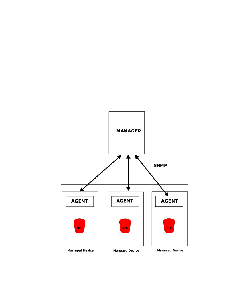
ZyAIR supports SNMP version one (SNMPv1) and version two c (SNMPv2c). The next figure illustrates
an SNMP management operation. SNMP is only available if TCP/IP is configured.
Figure 14-1 SNMP Management Model
An SNMP managed network consists of two main components: agents and a manager.

ZyAIR B-500 Wireless Access Point User’s Guide
14-2 SNMP Configuration
An agent is a management software module that resides in a managed device (the ZyAIR). An agent
translates the local management information from the managed device into a form compatible with SNMP.
The manager is the console through which network administrators perform network management functions.
It executes applications that control and monitor managed devices.
The managed devices contain object variables/managed objects that define each piece of information to be
collected about a device. Examples of variables include the number of packets received, node port status
etc. A Management Information Base (MIB) is a collection of managed objects. SNMP allows a manager
and agents to communicate for the purpose of accessing these objects.
SNMP itself is a simple request/response protocol based on the manager/agent model. The manager issues a
request and the agent returns responses using the following protocol operations:
• Get - Allows the manager to retrieve an object variable from the agent.
• GetNext - Allows the manager to retrieve the next object variable from a table or list within an agent.
In SNMPv1, when a manager wants to retrieve all elements of a table from an agent, it initiates a Get
operation, followed by a series of GetNext operations.
• Set - Allows the manager to set values for object variables within an agent.
• Trap - Used by the agent to inform the manager of some events.
14.2 Supported MIBs
The ZyAIR supports RFC-1215 and MIB II as defined in RFC-1213. The focus of the MIBs is to let
administrators collect statistic data and monitor status and performance.
14.3 SNMP Configuration
To configure SNMP, select option 22 from the main menu to open Menu 22 – SNMP Configuration as
shown next. The “community” for Get, Set and Trap fields is SNMP terminology for password.

ZyAIR B-500 Wireless Access Point User’s Guide
SNMP Configuration 14-3
Figure 14-2 Menu 22 SNMP Configuration
The following table describes the SNMP configuration parameters.
Table 14-1 Menu 22 SNMP Configuration
FIELD DESCRIPTION EXAMPLE
SNMP:
Get Community Type the Get Community, which is the password for the incoming
Get- and GetNext requests from the management station.
public
Set Community Type the Set Community, which is the password for incoming Set
requests from the management station.
public
Trusted Host If you enter a trusted host, your ZyAIR will only respond to SNMP
messages from this address. A blank (default) field means your
ZyAIR will respond to all SNMP messages it receives, regardless
of source.
0.0.0.0
Trap:
Community Type the trap community, which is the password sent with each
trap to the SNMP manager.
public
Destination Type the IP address of the station to send your SNMP traps to. 0.0.0.0
When you have completed this menu, press [ENTER] at the prompt “Press ENTER to confirm or ESC to
cancel” to save your configuration or press [ESC] to cancel and go back to the previous screen.
14.4 SNMP Traps
The ZyAIR will send traps to the SNMP manager when any one of the following events occurs:
Menu 22 - SNMP Configuration
SNMP:
Get Community= public
Set Community= public
Trusted Host= 0.0.0.0
Trap:
Community= public
Destination= 0.0.0.0
Press ENTER to Confirm or ESC to Cancel:

ZyAIR B-500 Wireless Access Point User’s Guide
14-4 SNMP Configuration
Table 14-2 SNMP Traps
TRAP # TRAP NAME DESCRIPTION
1 coldStart (defined in RFC-1215) A trap is sent after booting (power on).
2 warmStart (defined in RFC-1215) A trap is sent after booting (software reboot).
3 linkUp (defined in RFC-1215) A trap is sent when the port is up.
4 authenticationFailure (defined in
RFC-1215)
A trap is sent to the manager when receiving any SNMP
get or set requirements with wrong community
(password).
6 linkDown (defined in RFC-1215) A trap is sent when the port is down.
The following table maps the physical port and encapsulation to the interface type.
Table 14-3 Ports and Interface Types
PHYSICAL PORT/ENCAP INTERFACE TYPE
LAN port(s) enet0
Wireless port enet1
PPPoE encap pppoe
1483 encap mpoa
Ethernet encap enet-encap
PPPoA ppp

ZyAIR B-500 Wireless Access Point User’s Guide
System Security 15-1
Chapter 15
System Security
This chapter describes how to configure the system security on the ZyAIR.
15.1 System Security
You can configure the system password, an external RADIUS server and 802.1x in this menu.
15.1.1 System Password
Figure 15-1 Menu 23 System Security
You should change the default password. If you forget your password you have to restore the default
configuration file. Refer to the section on changing the system password in the Introducing the SMT chapter
and the section on resetting the ZyAIR in the Introducing the Web Configurator chapter.
15.1.2 Configuring External RADIUS Server
Enter 23 in the main menu to display Menu 23 – System Security.
Figure 15-2 Menu 23 System Security
From Menu 23- System Security, enter 2 to display Menu 23.2 – System Security – RADIUS Server as
shown next.
Menu 23 - System Security
1. Change Password
2. RADIUS Server
4. IEEE802.1x
Menu 23 - System Security
1. Change Password
2. RADIUS Server
4. IEEE802.1x

ZyAIR B-500 Wireless Access Point User’s Guide
15-2 System Security
Figure 15-3 Menu 23.2 System Security : RADIUS Server
The following table describes the fields in this menu.
Table 15-1 Menu 23.2 System Security : RADIUS Server
FIELD DESCRIPTION EXAMPLE
Authentication Server
Active Press [SPACE BAR] to select Yes and press [ENTER] to enable
user authentication through an external authentication server.
No
Server Address Enter the IP address of the external authentication server in
dotted decimal notation.
10.11.12.13
Port The default port of the RADIUS server for authentication is 1812.
You need not change this value unless your network
administrator instructs you to do so with additional information.
1812
Shared Secret Specify a password (up to 31 alphanumeric characters) as the
key to be shared between the external authentication server and
the access points.
The key is not sent over the network. This key must be the same
on the external authentication server and ZyAIR.
Accounting Server
Active Press [SPACE BAR] to select Yes and press [ENTER] to enable
user authentication through an external accounting server.
No
Server Address Enter the IP address of the external accounting server in dotted
decimal notation.
10.11.12.13
Menu 23.2 - System Security - RADIUS Server
Authentication Server:
Active= No
Server Address= 10.11.12.13
Port #= 1812
Shared Secret= ?
Accounting Server:
Active= No
Server Address= 10.11.12.13
Port #= 1813
Shared Secret= ?
Press ENTER to Confirm or ESC to Cancel:

ZyAIR B-500 Wireless Access Point User’s Guide
System Security 15-3
Table 15-1 Menu 23.2 System Security : RADIUS Server
FIELD DESCRIPTION EXAMPLE
Port The default port of the RADIUS server for accounting is 1813.
You need not change this value unless your network
administrator instructs you to do so with additional information.
1813
Shared Secret Specify a password (up to 31 alphanumeric characters) as the
key to be shared between the external accounting server and the
access points.
The key is not sent over the network. This key must be the same
on the external accounting server and ZyAIR.
When you have completed this menu, press [ENTER] at the prompt “Press ENTER to confirm or ESC to
cancel” to save your configuration or press [ESC] to cancel and go back to the previous screen.
15.1.3 802.1x
The IEEE 802.1x standards outline enhanced security methods for both the authentication of wireless
stations and encryption key management.
Follow the steps below to enable EAP authentication on your ZyAIR.
Step 1. From the main menu, enter 23 to display Menu23 – System Security.
Figure 15-4 Menu 23 System Security
Step 2. Enter 4 to display Menu 23.4 – System Security – IEEE802.1x.
Menu 23 - System Security
1. Change Password
2. RADIUS Server
4. IEEE802.1X

ZyAIR B-500 Wireless Access Point User’s Guide
15-4 System Security
Figure 15-5 Menu 23.4 System Security : IEEE802.1x
The following table describes the fields in this menu.
Table 15-2 Menu 23.4 System Security : IEEE802.1x
FIELD DESCRIPTION
Wireless Port
Control
Press [SPACE BAR] and select a security mode for the wireless LAN access.
Select No Authentication Required to allow any wireless stations access to your
wired network without entering usernames and passwords. This is the default setting.
Selecting Authentication Required means wireless stations have to enter usernames
and passwords before access to the wired network is allowed.
Select No Access Allowed to block all wireless stations access to the wired network.
ReAuthentica-
tion Timer
(in seconds)
Specify how often a wireless station has to re-enter username and password to stay
connected to the wired network.
This field is activated only when you select Authentication Required in the Wireless
Port Control field. Enter a time interval between 10 and 9999 (in seconds). The default
time interval is 1800 seconds (or 30 minutes).
Idle Timeout The ZyAIR automatically disconnects a wireless station from the wired network after a
period of inactivity. The wireless station needs to enter the username and password
again before access to the wired network is allowed.
This field is activated only when you select Authentication Required in the Wireless
Port Control field. The default time interval is 3600 seconds (or 1 hour).
Menu 23.4 - System Security - IEEE802.1X
Wireless Port Control= Authentication Required
ReAuthentication Timer (in second)= 1800
Idle Timeout (in second)= 3600
Authentication Databases= Local User Database Only
Press ENTER to Confirm or ESC to Cancel:

ZyAIR B-500 Wireless Access Point User’s Guide
System Security 15-5
Table 15-2 Menu 23.4 System Security : IEEE802.1x
FIELD DESCRIPTION
Authentication
Databases
This field is activated only when you select Authentication Required in the Wireless
Port Control field.
The authentication database contains wireless station login information. The local user
database is the built-in database on the ZyAIR. The RADIUS is an external server. Use
this field to decide which database the ZyAIR should use (first) to authenticate a
wireless station.
Before you specify the priority, make sure you have set up the corresponding database
correctly first.
Select Local User Database Only to have the ZyAIR just check the built-in user
database on the ZyAIR for a wireless station's username and password.
Select RADIUS Only to have the ZyAIR just check the user database on the specified
RADIUS server for a wireless station's username and password.
Select Local first, then RADIUS to have the ZyAIR first check the user database on
the ZyAIR for a wireless station's username and password. If the user name is not
found, the ZyAIR then checks the user database on the specified RADIUS server.
Select RADIUS first, then Local to have the ZyAIR first check the user database on
the specified RADIUS server for a wireless station's username and password. If the
ZyAIR cannot reach the RADIUS server, the ZyAIR then checks the local user
database on the ZyAIR. When the user name is not found or password does not match
in the RADIUS server, the ZyAIR will not check the local user database and the
authentication fails.
When you have completed this menu, press [ENTER] at the prompt “Press ENTER to confirm or ESC to
cancel” to save your configuration or press [ESC] to cancel and go back to the previous screen.
Once you enable user authentication, you need to specify an external RADIUS
server or create local user accounts on the ZyAIR for authentication.

ZyAIR B-500 Wireless Access Point User’s Guide
System Information and Diagnosis 16-1
Chapter 16
System Information and Diagnosis
This chapter covers the information and diagnostic tools in SMT menus 24.1 to 24.4.
16.1 Overview
These tools include updates on system status, port status, log and trace capabilities and upgrades for the
system software. This chapter describes how to use these tools in detail.
Type 24 in the main menu and press [ENTER] to open Menu 24 – System Maintenance, as shown in the
following figure.
Figure 16-1 Menu 24 System Maintenance
16.2 System Status
The first selection, System Status gives you information on the status and statistics of the ports, as shown
next. System Status is a tool that can be used to monitor your ZyAIR. Specifically, it gives you information
on your Ethernet and Wireless LAN status, number of packets sent and received.
To get to System Status, type 24 to go to Menu 24 – System Maintenance. From this menu, type 1.
System Status. There are two commands in Menu 24.1 – System Maintenance – Status. Entering 9 resets
the counters; pressing [ESC] takes you back to the previous screen.
Menu 24 – System Maintenance
1. System Status
2. System Information and Console Port Speed
3. Log and Trace
4. Diagnostic
5. Backup Configuration
6. Restore Configuration
7. Upload Firmware
8. Command Interpreter Mode
10. Time and Date Setting
Enter Menu Selection Number:

ZyAIR B-500 Wireless Access Point User’s Guide
16-2 System Information and Diagnosis
The following table describes the fields present in Menu 24.1 – System Maintenance – Status which are
read-only and meant for diagnostic purposes.
Figure 16-2 Menu 24.1 System Maintenance : Status
The following table describes the fields present in this menu.
Table 16-1 Menu 24.1 System Maintenance : Status
FIELD DESCRIPTION
Port This is the port type. Port types are: Ethernet and Wireless
Status This shows the status of the remote node.
TxPkts This is the number of transmitted packets to this remote node.
RxPkts This is the number of received packets from this remote node.
Cols This is the number of collisions on this connection.
Tx B/s This shows the transmission rate in bytes per second.
Rx B/s This shows the receiving rate in bytes per second.
Up Time This is the time this channel has been connected to the current remote node.
Ethernet Address This shows the MAC address of the port.
IP Address This shows the IP address of the network device connected to the port.
IP Mask This shows the subnet mask of the network device connected to the port.
DHCP This shows the DHCP setting (None or Client) for the port.
Menu 24.1 - System Maintenance - Status 00:01:51
Sat. Jan. 01, 2000
Port Status TxPkts RxPkts Cols Tx B/s Rx B/s Up Time
Ethernet 100M/Full 38 128 0 268 128 0:01:42
Wireless 16.5M 70 0 0 0 0 0:01:42
Port Ethernet Address IP Address IP Mask DHCP
Ethernet 00:A0:C5:00:00:04 192.168.1.2 255.255.255.0 None
Wireless 00:A0:C5:00:00:04
System up Time: 0:01:55
Press Command:
COMMANDS: 9-Reset Counters ESC-Exit

ZyAIR B-500 Wireless Access Point User’s Guide
System Information and Diagnosis 16-3
Table 16-1 Menu 24.1 System Maintenance : Status
FIELD DESCRIPTION
System Up Time This is the time the ZyAIR is up and running from the last reboot.
16.3 System Information
To get to the System Information:
Step 1. Enter 24 to display Menu 24 – System Maintenance.
Step 2. Enter 2 to display Menu 24.2 – System Information and Console Port Speed.
Step 3. From this menu you have two choices as shown in the next figure:
Figure 16-3 Menu 24.2 System Information and Console Port Speed
The ZyAIR has an internal console port for support personnel only. Do not open
the ZyAIR as it will void your warranty.
16.3.1 System Information
Enter 1 in menu 24.2 to display the screen shown next.
Figure 16-4 Menu 24.2.1 System Information : Information
Menu 24.2 - System Information and Console Port Speed
1. System Information
2. Console Port Speed
Please enter selection:
Menu 24.2.1 - System Maintenance - Information
Name: B-500
Routing: BRIDGE
ZyNOS F/W Version: V3.50(HL.0)b1 | 09/19/2003
Country Code: 255
LAN
Ethernet Address: 00:A0:C5:00:00:04
IP Address: 192.168.1.2
IP Mask: 255.255.255.0
DHCP: None
Press ESC or RETURN to Exit:

ZyAIR B-500 Wireless Access Point User’s Guide
16-4 System Information and Diagnosis
The following table describes the fields in this menu.
Table 16-2 Menu 24.2.1 System Maintenance : Information
FIELD DESCRIPTION
Name Displays the system name of your ZyAIR. This information can be changed in
Menu 1 – General Setup.
Routing Refers to the routing protocol used.
ZyNOS F/W
Version
Refers to the ZyNOS (ZyXEL Network Operating System) system firmware version.
ZyNOS is a registered trademark of ZyXEL Communications Corporation.
Country Code Refers to the country code of the firmware.
LAN
Ethernet Address Refers to the Ethernet MAC (Media Access Control) of your ZyAIR.
IP Address This is the IP address of the ZyAIR in dotted decimal notation.
IP Mask This shows the subnet mask of the ZyAIR.
DHCP This field shows the DHCP setting of the ZyAIR.
When you have completed this menu, press [ENTER] at the prompt “Press ENTER to confirm or ESC to
cancel” to save your configuration or press [ESC] to cancel and go back to the previous screen.
16.3.2 Console Port Speed
You can set up different port speeds for the console port through Menu 24.2.2 – System Maintenance –
Console Port Speed. Your ZyAIR supports 9600 (default), 19200, 38400, 57600 and 115200 bps console
port speeds. Press [SPACE BAR] and then [ENTER] to select the desired speed in menu 24.2.2, as shown
in the following figure.
Figure 16-5 Menu 24.2.2 System Maintenance : Change Console Port Speed
After you changed the console port speed on your ZyAIR, you must also make the same change to the
console port speed parameter of your communication software.
Menu 24.2.2 – System Maintenance – Change Console Port Speed
Console Port Speed: 9600
Press ENTER to Confirm or ESC to Cancel:

ZyAIR B-500 Wireless Access Point User’s Guide
System Information and Diagnosis 16-5
16.4 Log and Trace
Your ZyAIR provides the error logs and trace records that are stored locally.
16.4.1 Viewing Error Log
The first place you should look for clues when something goes wrong is the error log. Follow the
procedures to view the local error/trace log:
Step 1. Type 24 in the main menu to display Menu 24 – System Maintenance.
Step 2. From menu 24, type 3 to display Menu 24.3 – System Maintenance – Log and Trace.
Figure 16-6 Menu 24.3 System Maintenance : Log and Trace
Step 3. Enter 1 from Menu 24.3 – System Maintenance – Log and Trace and press [ENTER] twice to
display the error log in the system.
After the ZyAIR finishes displaying the error log, you will have the option to clear it. Samples of typical
error and information messages are presented in the next figure.
Figure 16-7 Sample Error and Information Messages
16.5 Diagnostic
The diagnostic facility allows you to test the different aspects of your ZyAIR to determine if it is working
properly. Menu 24.4 allows you to choose among various types of diagnostic tests to evaluate your system,
as shown in the following figure.
Menu 24.3 - System Maintenance - Log and Trace
1. View Error Log
Please enter selection:
13 Sat Jan 1 00:00:00 2000 PP0d INFO LAN promiscuous mode <1>
14 Sat Jan 1 00:00:00 2000 PINI INFO Last errorlog repeat 1 Times
15 Sat Jan 1 00:00:00 2000 PINI INFO main: init completed
16 Sat Jan 1 00:00:02 2000 PP05 -WARN SNMP TRAP 3: link up
17 Sat Jan 1 00:00:02 2000 PP13 INFO sending request to NTP server(6)
20 Sat Jan 1 00:00:30 2000 PSSV -WARN SNMP TRAP 0: cold start
Clear Error Log (y/n):

ZyAIR B-500 Wireless Access Point User’s Guide
16-6 System Information and Diagnosis
Figure 16-8 Menu 24.4 System Maintenance : Diagnostic
Follow the procedure next to get to display this menu:
Step 1. From the main menu, type 24 to open Menu 24 – System Maintenance.
Step 2. From this menu, type 4. Diagnostic to open Menu 24.4 – System Maintenance – Diagnostic.
The following table describes the diagnostic tests available in menu 24.4 for your ZyAIR and the
connections.
Table 16-3 Menu 24.4 System Maintenance Menu : Diagnostic
FIELD DESCRIPTION
Ping Host Ping the host to see if the links and TCP/IP protocol on both systems are working.
DHCP Release Release the IP address assigned by the DHCP server.
DHCP Renewal Get a new IP address from the DHCP server.
Reboot System Reboot the ZyAIR.
Host IP Address If you typed 1 to Ping Host, now type the address of the computer you want to ping.
Menu 24.4 - System Maintenance – Diagnostic
TCP/IP
1. Ping Host
2. DHCP Release
3. DHCP Renewal
System
11. Reboot System
Enter Menu Selection Number:
Host IP Address= N/A

ZyAIR B-500 Wireless Access Point User’s Guide
Firmware and Configuraiton File Maintenance 17-1
Chapter 17
Firmware and Configuration File
Maintenance
This chapter tells you how to backup and restore your configuration file as well as upload new
firmware and configuration files using the SMT screens.
17.1 Filename Conventions
The configuration file (often called the romfile or rom-0) contains the factory default settings in the menus
such as password and TCP/IP Setup, etc. It arrives from ZyXEL with a rom filename extension. Once you
have customized the ZyAIR's settings, they can be saved back to your computer under a filename of your
choosing.
ZyNOS (ZyXEL Network Operating System sometimes referred to as the “ras” file) is the system firmware
and has a “bin” filename extension. With many FTP and TFTP clients, the filenames are similar to those
seen next.
ftp> put firmware.bin ras
This is a sample FTP session showing the transfer of the computer file " firmware.bin" to the ZyAIR.
ftp> get rom-0 config.cfg
This is a sample FTP session saving the current configuration to the computer file config.cfg.
If your [T]FTP client does not allow you to have a destination filename different than the source, you will
need to rename them as the ZyAIR only recognizes “rom-0” and “ras”. Be sure you keep unaltered copies
of both files for later use.
The following table is a summary. Please note that the internal filename refers to the filename on the
ZyAIR and the external filename refers to the filename not on the ZyAIR, that is, on your computer, local
network or FTP site and so the name (but not the extension) will vary. After uploading new firmware see
the ZyNOS F/W Version field in Menu 24.2.1 – System Maintenance – Information to confirm that you
have uploaded the correct firmware version.

ZyAIR B-500 Wireless Access Point User’s Guide
17-2 Firmware and Configuraiton File Maintenance
Table 17-1 Filename Conventions
FILE TYPE INTERNAL
NAME
EXTERNAL
NAME
DESCRIPTION
Configuration File Rom-0 *.rom This is the configuration filename on the ZyAIR.
Uploading the rom-0 file replaces the entire ROM file
system, including your ZyAIR configurations,
system-related data (including the default
password), the error log and the trace log.
Firmware Ras *.bin This is the generic name for the ZyNOS firmware on
the ZyAIR.
17.2 Backup Configuration
Option 5 from Menu 24 – System Maintenance allows you to backup the current ZyAIR configuration to
your computer. Backup is highly recommended once your ZyAIR is functioning properly. FTP is the
preferred method, although TFTP can also be used.
Please note that the terms “download” and “upload” are relative to the computer. Download means to
transfer from the ZyAIR to the computer, while upload means from your computer to the ZyAIR.
17.2.1 Backup Configuration Using FTP
Enter 5 in Menu 24 – System Maintenance to get the following screen.
Figure 17-1 Menu 24.5 Backup Configuration
Menu 24.5 – Backup Configuration
To transfer the configuration file to your workstation, follow the
procedure below:
1. Launch the FTP client on your workstation.
2. Type "open" and the IP address of your router. Then type "root" and
SMT password as requested.
3. Locate the ‘rom-0’ file.
4. Type ‘get rom-0’ to back up the current router configuration to your
workstation.
For details on FTP commands, please consult the documentation of your FTP
client program. For details on backup using TFTP (note that you must
remain in the menu to back up using TFTP), please see your router manual.
Press ENTER to Exit:

ZyAIR B-500 Wireless Access Point User’s Guide
Firmware and Configuraiton File Maintenance 17-3
17.2.2 Using the FTP command from the DOS Prompt
Step 1. Launch the FTP client on your computer.
Step 2. Enter “open” and the IP address of your ZyAIR.
Step 3. Press [ENTER] when prompted for a username.
Step 4. Enter “root” and your SMT password as requested. The default is 1234.
Step 5. Enter “bin” to set transfer mode to binary.
Step 6. Use “get” to transfer files from the ZyAIR to the computer, for example, “get rom-0 config.rom”
transfers the configuration file on the ZyAIR to your computer and renames it “config.rom”. See
earlier in this chapter for more information on filename conventions.
Step 7. Enter “quit” to exit the FTP prompt.
Figure 17-2 FTP Session Example
The following table describes some of the commands that you may see in third party FTP clients.
Table 17-2 General Commands for Third Party FTP Clients
COMMAND DESCRIPTION
Host Address Enter the address of the host server.
Login Type Anonymous.
This is when a user I.D. and password is automatically supplied to the server for
anonymous access. Anonymous logins will work only if your ISP or service
administrator has enabled this option.
Normal.
The server requires a unique User ID and Password to login.
Transfer Type Transfer files in either ASCII (plain text format) or in binary mode.
331 Enter PASS command
Password:
230 Logged in
ftp> bin
200 Type I OK
ftp> get rom-0 zyxel.rom
200 Port command okay
150 Opening data connection for STOR ras
226 File received OK
ftp: 327680 bytes sent in 1.10Seconds 297.89Kbytes/sec.
ftp> quit

ZyAIR B-500 Wireless Access Point User’s Guide
17-4 Firmware and Configuraiton File Maintenance
Table 17-2 General Commands for Third Party FTP Clients
COMMAND DESCRIPTION
Initial Remote
Directory
Specify the default remote directory (path).
Initial Local
Directory
Specify the default local directory (path).
17.2.3 Backup Configuration Using TFTP
The ZyAIR supports the up/downloading of the firmware and the configuration file using TFTP (Trivial
File Transfer Protocol) over LAN. Although TFTP should work over WAN as well, it is not recommended.
To use TFTP, your computer must have both telnet and TFTP clients. To backup the configuration file,
follow the procedure shown next:
Step 1. Use telnet from your computer to connect to the ZyAIR and log in. Because TFTP does not
have any security checks, the ZyAIR records the IP address of the telnet client and accepts
TFTP requests only from this address.
Step 2. Put the SMT in command interpreter (CI) mode by entering 8 in Menu 24 – System
Maintenance.
Step 3. Enter command “sys stdio 0” to disable the SMT timeout, so the TFTP transfer will not be
interrupted. Enter command “sys stdio 5” to restore the five-minute SMT timeout (default)
when the file transfer is complete.
Step 4. Launch the TFTP client on your computer and connect to the ZyAIR. Set the transfer mode to
binary before starting data transfer.
Step 5. Use the TFTP client (see the example below) to transfer files between the ZyAIR and the
computer. The file name for the configuration file is rom-0 (rom-zero, not capital o).
Note that the telnet connection must be active and the SMT in CI mode before and during the TFTP
transfer. For details on TFTP commands (see following example), please consult the documentation of your
TFTP client program. For UNIX, use “get” to transfer from the ZyAIR to the computer and “binary” to set
binary transfer mode.
17.2.4 Example: TFTP Command
The following is an example TFTP command:
TFTP [-i] host get rom-0 config.rom

ZyAIR B-500 Wireless Access Point User’s Guide
Firmware and Configuraiton File Maintenance 17-5
where “i” specifies binary image transfer mode (use this mode when transferring binary files), “host” is the
ZyAIR IP address, “get” transfers the file source on the ZyAIR (rom-0 name of the configuration file on
the ZyAIR) to the file destination on the computer and renames it config.rom.
The following table describes some of the fields that you may see in third party TFTP clients.
Table 17-3 General Commands for Third Party TFTP Clients
COMMAND DESCRIPTION
Host Enter the IP address of the ZyAIR. 192.168.1.2 is the ZyAIR’s default IP
address when shipped.
Send/Fetch Use “Send” to upload the file to the ZyAIR and “Fetch” to back up the file on
your computer.
Local File Enter the path and name of the firmware file (*.bin extension) or configuration
file (*.rom extension) on your computer.
Remote File This is the filename on the ZyAIR. The filename for the firmware is “ras” and for
the configuration file, is “rom-0”.
Binary Transfer the file in binary mode.
Abort Stop transfer of the file.
17.3 Restore Configuration
Menu 24.6 –- System Maintenance – Restore Configuration allows you to restore the configuration via
FTP or TFTP to your ZyAIR. The preferred method is FTP. Note that this function erases the current
configuration before restoring the previous backup configuration; please do not attempt to restore unless
you have a backup configuration stored on disk. To restore configuration using FTP or TFTP is the same as
uploading the configuration file, please refer to the following sections on FTP and TFTP file transfer for
more details. The ZyAIR restarts automatically after the file transfer is complete.

ZyAIR B-500 Wireless Access Point User’s Guide
17-6 Firmware and Configuraiton File Maintenance
Figure 17-3 Menu 24.6 Restore Configuration
17.4 Uploading Firmware and Configuration Files
Menu 24.7 – System Maintenance – Upload Firmware allows you to upgrade the firmware and the
configuration file.
WARNING!
PLEASE WAIT A FEW MINUTES FOR THE ZYAIR TO RESTART AFTER FIRMWARE
OR CONFIGURATION FILE UPLOAD. INTERRUPTING THE UPLOAD PROCESS
MAY PERMANENTLY DAMAGE YOUR ZYAIR.
Figure 17-4 Menu 24.7 System Maintenance : Upload Firmware
The configuration data, system-related data, the error log and the trace log are all stored in the configuration
file. Please be aware that uploading the configuration file replaces everything contained within.
Menu 24.6 – Restore Configuration
To transfer the firmware and the configuration file, follow the procedure
below:
1. Launch the FTP client on your workstation.
2. Type "open" and the IP address of your router. Then type "root" and
SMT password as requested.
3. Type “put backupfilename rom-0” where backupfilename is the name of
your backup configuration file on your workstation and rom-spt is the
Remote file name on the router. This restores the configuration to your
router.
4. The system reboots automatically after a successful file transfer.
For details on FTP commands, please consult the documentation of your FTP
client program. For details on restoring using TFTP (note that you must
remain in the menu to back up using TFTP), please see your router manual.
Press ENTER to Exit:
Menu 24.7 - System Maintenance - Upload Firmware
1. Upload System Firmware
2. Upload System Configuration File
Enter Menu Selection Number:

ZyAIR B-500 Wireless Access Point User’s Guide
Firmware and Configuraiton File Maintenance 17-7
17.4.1 Firmware Upload
FTP is the preferred method for uploading the firmware and configuration. To use this feature, your
computer must have an FTP client.
When you telnet into the ZyAIR, you will see the following screens for uploading firmware and the
configuration file using FTP.
Figure 17-5 Menu 24.7.1 System Maintenance : Upload System Firmware
17.4.2 Configuration File Upload
You see the following screen when you telnet into menu 24.7.2.
Menu 24.7.1 - System Maintenance - Upload System Firmware
To upload the system firmware, follow the procedure below:
1. Launch the FTP client on your workstation.
2. Type "open" and the IP address of your system. Then type "root" and
SMT password as requested.
3. Type "put firmwarefilename ras" where "firmwarefilename" is the name
of your firmware upgrade file on your workstation and "ras" is the
remote file name on the system.
4. The system reboots automatically after a successful firmware upload.
For details on FTP commands, please consult the documentation of your FTP
client program. For details on uploading system firmware using TFTP (note
that you must remain on this menu to upload system firmware using TFTP),
please see your manual.
Press ENTER to Exit:

ZyAIR B-500 Wireless Access Point User’s Guide
17-8 Firmware and Configuraiton File Maintenance
Figure 17-6 Menu 24.7.2 System Maintenance : Upload System Configuration File
To transfer the firmware and the configuration file, follow these examples:
17.4.3 Using the FTP command from the DOS Prompt Example
Step 1. Launch the FTP client on your computer.
Step 2. Enter “open” and the IP address of your ZyAIR.
Step 3. Press [ENTER] when prompted for a username.
Step 4. Enter “root” and your SMT password as requested. The default is 1234.
Step 5. Enter “bin” to set transfer mode to binary.
Step 6. Use “put” to transfer files from the computer to the ZyAIR, e.g., put firmware.bin ras transfers
the firmware on your computer (firmware.bin) to the ZyAIR and renames it “ras”. Similarly “put
config.rom rom-0” transfers the configuration file on your computer (config.rom) to the ZyAIR
and renames it “rom-0”. Likewise “get rom-0 config.rom” transfers the configuration file on the
ZyAIR to your computer and renames it “config.rom.” See earlier in this chapter for more
information on filename conventions.
Step 7. Enter “quit” to exit the FTP prompt.
Menu 24.7.2 - System Maintenance - Upload System Configuration File
To upload the system configuration file, follow the procedure below:
1. Launch the FTP client on your workstation.
2. Type "open" and the IP address of your system. Then type "root" and
SMT password as requested.
3. Type "put configurationfilename rom-0" where "configurationfilename"
is the name of your system configuration file on your workstation, which
will be transferred to the "rom-0" file on the system.
4. The system reboots automatically after the upload system configuration
file process is complete.
For details on FTP commands, please consult the documentation of your FTP
client program. For details on uploading system firmware using TFTP (note
that you must remain on this menu to upload system firmware using TFTP),
please see your manual.
Press ENTER to Exit:

ZyAIR B-500 Wireless Access Point User’s Guide
Firmware and Configuraiton File Maintenance 17-9
Figure 17-7 FTP Session Example
More commands that you may find in third party FTP clients, are listed earlier in this chapter.
17.4.4 TFTP File Upload
The ZyAIR also supports the up/downloading of the firmware and the configuration file using TFTP
(Trivial File Transfer Protocol) over LAN. Although TFTP should work over WAN as well, it is not
recommended.
To use TFTP, your computer must have both telnet and TFTP clients. To transfer the firmware and the
configuration file, follow the procedure shown next:
Step 1. Use telnet from your computer to connect to the ZyAIR and log in. Because TFTP does not have
any security checks, the ZyAIR records the IP address of the telnet client and accepts TFTP
requests only from this address.
Step 2. Put the SMT in command interpreter (CI) mode by entering 8 in Menu 24 – System
Maintenance.
Step 3. Enter the command “sys stdio 0” to disable the SMT timeout, so the TFTP transfer will not be
interrupted. Enter command “sys stdio 5” to restore the five-minute SMT timeout (default) when
the file transfer is complete.
Step 4. Launch the TFTP client on your computer and connect to the ZyAIR. Set the transfer mode to
binary before starting data transfer.
Step 5. Use the TFTP client (see the example below) to transfer files between the ZyAIR and the
computer. The file name for the firmware is “ras” and the configuration file is “rom-0” (rom-
zero, not capital o).
Note that the telnet connection must be active and the SMT in CI mode before and during the TFTP
transfer. For details on TFTP commands (see following example), please consult the documentation of your
TFTP client program. For UNIX, use “get” to transfer from the ZyAIR to the computer, “put” the other way
around, and “binary” to set binary transfer mode.
331 Enter PASS command
Password:
230 Logged in
ftp> bin
200 Type I OK
ftp> put firmware.bin ras
200 Port command okay
150 Opening data connection for STOR ras
226 File received OK
ftp: 327680 bytes sent in 1.10Seconds 297.89Kbytes/sec.
ftp> quit

ZyAIR B-500 Wireless Access Point User’s Guide
17-10 Firmware and Configuraiton File Maintenance
17.4.5 Example: TFTP Command
The following is an example TFTP command:
TFTP [-i] host put firmware.bin ras
where “i” specifies binary image transfer mode (use this mode when transferring binary files), “host” is the
ZyAIR’s IP address, “put” transfers the file source on the computer (firmware.bin – name of the firmware
on the computer) to the file destination on the remote host (ras - name of the firmware on the ZyAIR).
Commands that you may see in third party TFTP clients are listed earlier in this chapter.

ZyAIR B-500 Wireless Access Point User’s Guide
System Maintenance and Information 18-1
Chapter 18
System Maintenance and Information
This chapter leads you through SMT menus 24.8 and 24.10.
18.1 Command Interpreter Mode
The Command Interpreter (CI) is a part of the main system firmware. The CI provides much of the same
functionality as the SMT, while adding some low-level setup and diagnostic functions. Enter the CI from
the SMT by selecting menu 24.8. See the included disk or the zyxel.com web site for more detailed
information on CI commands. Enter 8 from Menu 24 – System Maintenance. A list of valid commands
can be found by typing help or ? at the command prompt. Type “exit” to return to the SMT main menu
when finished.
Figure 18-1 Menu 24 System Maintenance
Figure 18-2 Valid CI Commands
Menu 24 – System Maintenance
1. System Status
2. System Information and Console Port Speed
3. Log and Trace
4. Diagnostic
5. Backup Configuration
6. Restore Configuration
7. Upload Firmware
8. Command Interpreter Mode
10. Time and Date Setting
Enter Menu Selection Number:
Copyright (c) 1994 - 2003 ZyXEL Communications Corp.
B-500> ?
Valid commands are:
sys exit device ether
config wlan ip ppp
bridge hdap cnm radius
8021x
B-500>

ZyAIR B-500 Wireless Access Point User’s Guide
18-2 System Maintenance and Information
18.2 Time and Date Setting
The ZyAIR keeps track of the time and date. There is also a software mechanism to set the time manually
or get the current time and date from an external server when you turn on your ZyAIR. Menu 24.10 allows
you to update the time and date settings of your ZyAIR. The real time is then displayed in the ZyAIR error
logs and firewall logs.
Step 1. Select menu 24 in the main menu to open Menu 24 – System Maintenance.
Step 2. Then enter 10 to go to Menu 24.10 – System Maintenance – Time and Date Setting to update
the time and date settings of your ZyAIR as shown in the following screen.
Figure 18-3 Menu 24.10 System Maintenance : Time and Date Setting
The following table describes the fields in this menu.
Menu 24.10 - System Maintenance - Time and Date Setting
Use Time Server when Bootup= NTP (RFC-1305)
Time Server Address= 128.105.39.21
Current Time: 05 : 47 : 19
New Time (hh:mm:ss): 05 : 47 : 17
Current Date: 2000 - 01 - 01
New Date (yyyy-mm-dd): 2000 - 01 - 01
Time Zone= GMT
Daylight Saving= No
Start Date (mm-dd): 01 - 01
End Date (mm-dd): 01 - 01
Press ENTER to Confirm or ESC to Cancel:

ZyAIR B-500 Wireless Access Point User’s Guide
System Maintenance and Information 18-3
Table 18-1 Menu 24.10 System Maintenance : Time and Date Setting
FIELD DESCRIPTION
Use Time Server
when Bootup
Enter the time service protocol that your time server sends when you turn on the
ZyAIR. Not all time servers support all protocols, so you may have to check with
your ISP/network administrator or use trial and error to find a protocol that works.
The main differences between them are the format.
Daytime (RFC 867) format is day/month/year/time zone of the server.
Time (RFC-868) format displays a 4-byte integer giving the total number of
seconds since 1970/1/1 at 0:0:0.
NTP (RFC-1305) is similar to Time (RFC-868).
None. The default, enter the time manually.
Time Server
Address
Enter the IP address or domain name of your time server. Check with your
ISP/network administrator if you are unsure of this information.
Current Time This field displays an updated time only when you reenter this menu.
New Time Enter the new time in hour, minute and second format.
Current Date This field displays an updated date only when you re-enter this menu.
New Date Enter the new date in year, month and day format.
Time Zone Press [SPACE BAR] and then [ENTER] to set the time difference between your
time zone and Greenwich Mean Time (GMT).
Daylight Saving If you use daylight savings time, then choose Yes.
Start Date If using daylight savings time, enter the month and day that it starts on.
End Date If using daylight savings time, enter the month and day that it ends on
Once you have filled in this menu, press [ENTER] at the message “Press ENTER to Confirm or ESC to
Cancel“ to save your configuration, or press [ESC] to cancel.
18.2.1 Resetting the Time
The ZyAIR resets the time in three instances:
i. On leaving menu 24.10 after making changes.
ii. When the ZyAIR starts up, if there is a time server configured in menu 24.10.
iii. 24-hour intervals after starting.

Appendices
VI
Part VI:
APPENDICES
This part provides troubleshooting and background information about setting up your computer’s
IP address, wireless LAN, 802.1x and IP subnetting. It also provides information on the command
interpreter interface, NetBIOS commands and logs.

ZyAIR B-500 Wireless Access Point User’s Guide
Troubleshooting A-1
Appendix A
Troubleshooting
This appendix covers potential problems and possible remedies. After each problem description,
some instructions are provided to help you to diagnose and to solve the problem.
Problems Starting Up the ZyAIR
Chart A-1 Troubleshooting the Start-Up of Your ZyAIR
PROBLEM CORRECTIVE ACTION
None of the LEDs
turn on when I
plug in the power
adaptor.
Make sure you are using the supplied power adaptor and that it is plugged in to an
appropriate power source. Check that the power source is turned on.
If the problem persists, you may have a hardware problem. In this case, you should
contact your local vendor.
The ZyAIR
reboots
automatically
sometimes.
The supplied power to the ZyAIR is too low. Check that the ZyAIR is receiving
enough power.
Make sure the power source is working properly.
Problems with the Ethernet Interface
Chart A-2 Troubleshooting the Ethernet Interface
PROBLEM CORRECTIVE ACTION
Cannot access the
ZyAIR from the
LAN.
If the ETHN LED on the front panel is off, check the Ethernet cable connection
between your ZyAIR and the Ethernet device connected to the ETHERNET port.
Check for faulty Ethernet cables.
Make sure your computer’s Ethernet adapter is installed and working properly.
Check the IP address of the Ethernet device. Verify that the IP address and the
subnet mask of the ZyAIR, the Ethernet device and your computer are on the same
subnet.

ZyAIR B-500 Wireless Access Point User’s Guide
A-2 Troubleshooting
Chart A-2 Troubleshooting the Ethernet Interface
PROBLEM CORRECTIVE ACTION
I cannot ping any
computer on the
LAN.
If the ETHN LED on the front panel is off, check the Ethernet cable connections
between your ZyAIR and the Ethernet device.
Check the Ethernet cable connections between the Ethernet device and the LAN
computers.
Check for faulty Ethernet cables.
Make sure the LAN computer’s Ethernet adapter is installed and working properly.
Verify that the IP address and the subnet mask of the ZyAIR, the Ethernet device
and the LAN computers are on the same subnet.
Problems with the Password
Chart A-3 Troubleshooting the Password
PROBLEM CORRECTIVE ACTION
I cannot access
the ZyAIR.
The Password and Username fields are case-sensitive. Make sure that you enter
the correct password and username using the proper casing.
Use the RESET button on the top panel of the ZyAIR to restore the factory default
configuration file (hold this button in for about 10 seconds or until the link LED turns
red). This will restore all of the factory defaults including the password.
Problems with Telnet
Chart A-4 Troubleshooting Telnet
PROBLEM CORRECTIVE ACTION
I cannot access
the ZyAIR through
Telnet.
Refer to the Problems with the Ethernet Interface section for instructions on checking
your Ethernet connection.

ZyAIR B-500 Wireless Access Point User’s Guide
Troubleshooting A-3
Problems with the WLAN Interface
Chart A-5 Troubleshooting the WLAN Interface
PROBLEM CORRECTIVE ACTION
Cannot access the
ZyAIR from the
WLAN.
Make sure the wireless adapter on the wireless station is working properly.
Check that both the ZyAIR and your wireless station are using the same ESSID,
channel and WEP keys (if WEP encryption is activated).
I cannot ping any
computer on the
WLAN.
Make sure the wireless adapter on the wireless station(s) is working properly.
Check that both the ZyAIR and wireless station(s) are using the same ESSID,
channel and WEP keys (if WEP encryption is activated).

ZyAIR B-500 Wireless Access Point User’s Guide
Brute-Force Password Guessing Protection B-1
Appendix B
Brute-Force Password Guessing
Protection
The following describes the commands for enabling, disabling and configuring the brute-force password
guessing protection mechanism for the password. See the Command Interpreter appendix for information
on the command structure.
Chart B-1 Brute-Force Password Guessing Protection Commands
COMMAND DESCRIPTION
sys pwderrtm This command displays the brute-force guessing password protection settings.
sys pwderrtm 0 This command turns off the password's protection from brute-force guessing.
sys pwderrtm N This command sets the password protection to block all access attempts for N (a
number from 1 to 60) minutes after the third time an incorrect password is entered.
Example
sys pwderrtm 5 This command sets the password protection to block all access attempts for five minutes after
the third time an incorrect password is entered.
By default, the brute-force password guessing protection is turned ON with a 3-minute wait time.
ZyAIR B-500 Wireless Access Point User’s Guide
Setting Up Your Computer’s IP Address C-1
Appendix C
Setting up Your Computer’s IP Address
All computers must have a 10M or 100M Ethernet adapter card and TCP/IP installed.
Windows 95/98/Me/NT/2000/XP, Macintosh OS 7 and later operating systems and all versions of
UNIX/LINUX include the software components you need to install and use TCP/IP on your computer.
Windows 3.1 requires the purchase of a third-party TCP/IP application package.
TCP/IP should already be installed on computers using Windows NT/2000/XP, Macintosh OS 7 and later
operating systems.
After the appropriate TCP/IP components are installed, configure the TCP/IP settings in order to
"communicate" with your network.
If you manually assign IP information instead of using dynamic assignment, make sure that your computers
have IP addresses that place them in the same subnet as the ZyAIR's LAN port.
Windows 95/98/Me
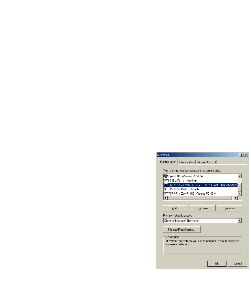
Click Start, Settings, Control Panel and double-click the
Network icon to open the Network window.
The Network window Configuration tab displays a list of installed components. You need a network
adapter, the TCP/IP protocol and Client for Microsoft Networks.

ZyAIR B-500 Wireless Access Point User’s Guide
C-2 Setting Up Your Computer’s IP Address
If you need the adapter:
a. In the Network window, click Add.
b. Select Adapter and then click Add.
c. Select the manufacturer and model of your network adapter and then click OK.
If you need TCP/IP:
a. In the Network window, click Add.
b. Select Protocol and then click Add.
c. Select Microsoft from the list of manufacturers.
d. Select TCP/IP from the list of network protocols and then click OK.
If you need Client for Microsoft Networks:
a. Click Add.
b. Select Client and then click Add.
c. Select Microsoft from the list of manufacturers.
d. Select Client for Microsoft Networks from the list of network clients and then click OK.
e. Restart your computer so the changes you made take effect.
In the Network window Configuration tab, select your network adapter's TCP/IP entry and click
Properties.
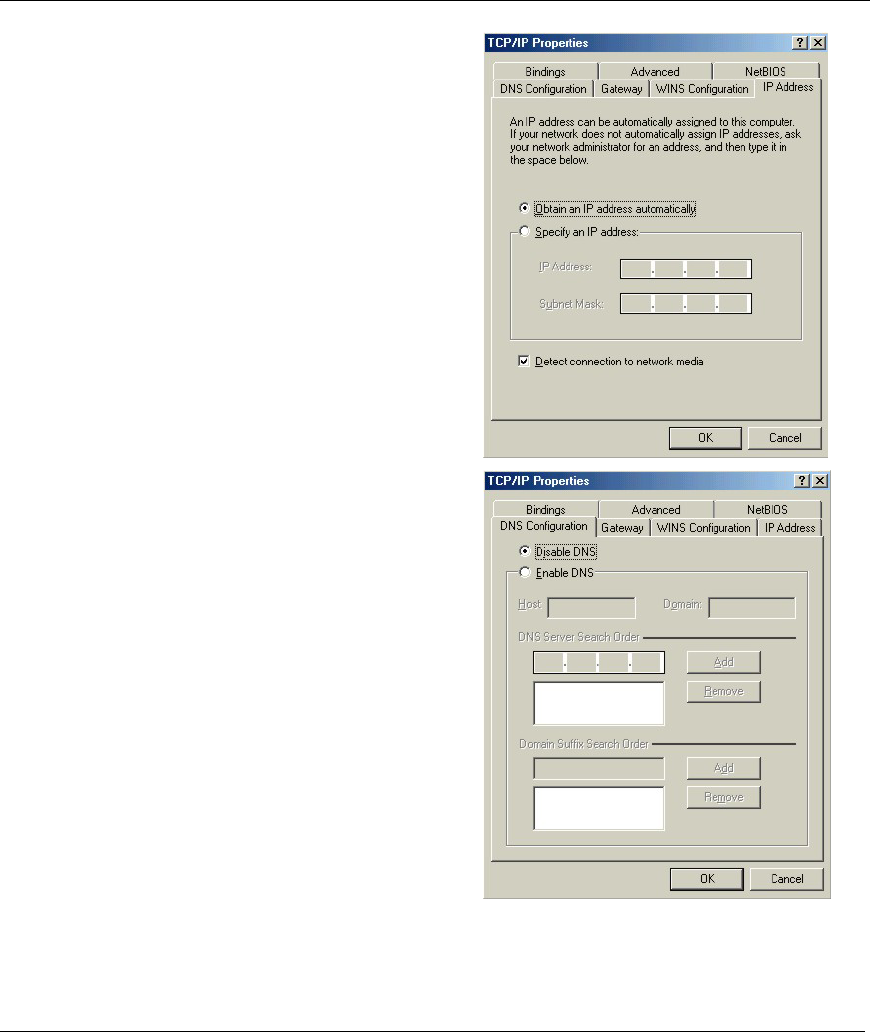
ZyAIR B-500 Wireless Access Point User’s Guide
Setting Up Your Computer’s IP Address C-3
1. Click the IP Address tab.
-If your IP address is dynamic, select Obtain an
IP address automatically.
-If you have a static IP address, select Specify
an IP address and type your information into
the IP Address and Subnet Mask fields.
2. Click the DNS Configuration tab.
-If you do not know your DNS information, select
Disable DNS.
-If you know your DNS information, select
Enable DNS and type the information in the
fields below (you may not need to fill them all
in).
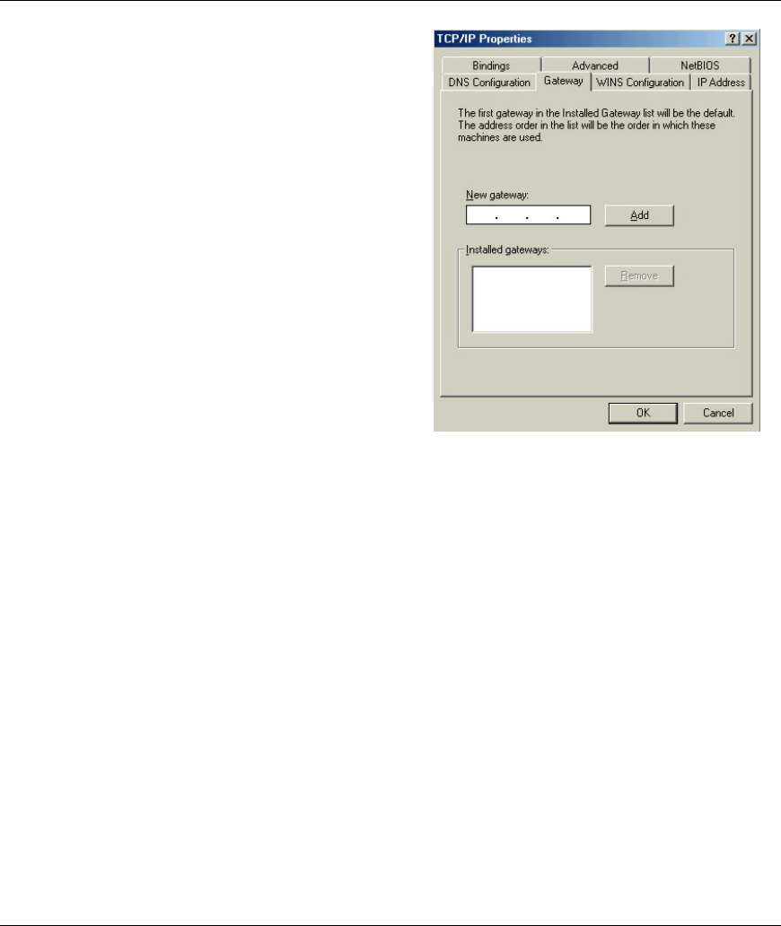
ZyAIR B-500 Wireless Access Point User’s Guide
C-4 Setting Up Your Computer’s IP Address
3.
Click the Gateway tab.
-If you do not know your gateway’s IP address,
remove previously installed gateways.
-If you have a gateway IP address, type it in the
New gateway field and click Add.
4. Click OK to save and close the TCP/IP Properties window.
5. Click OK to close the Network window. Insert the Windows CD if prompted.
6. Turn on your ZyAIR and restart your computer when prompted.
Verifying Your Computer’s IP Address
1. Click Start and then Run.
2. In the Run window, type "winipcfg" and then click OK to open the IP Configuration window.
3. Select your network adapter. You should see your computer's IP address, subnet mask and default
gateway.
Windows 2000/NT/XP
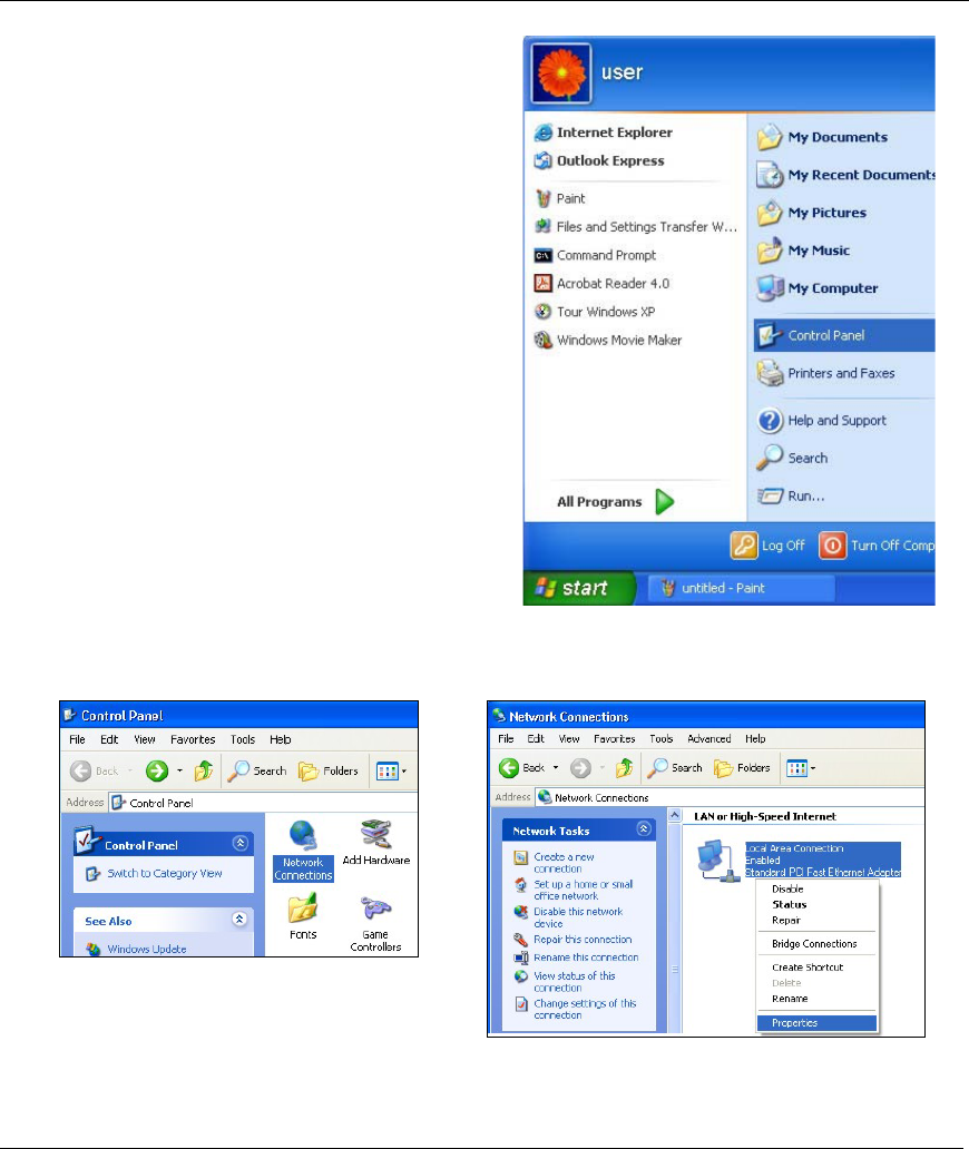
ZyAIR B-500 Wireless Access Point User’s Guide
Setting Up Your Computer’s IP Address C-5
1. For Windows XP, click start, Control Panel. In
Windows 2000/NT, click Start, Settings, Control
Panel.
2. For Windows XP, click Network
Connections. For Windows 2000/NT, click
Network and Dial-up Connections.
3. Right-click Local Area Connection and
then click Properties.
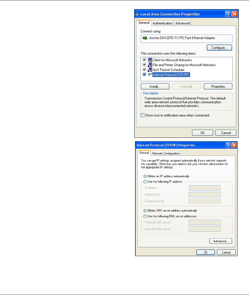
ZyAIR B-500 Wireless Access Point User’s Guide
C-6 Setting Up Your Computer’s IP Address
4. Select Internet Protocol (TCP/IP) (under the
General tab in Win XP) and click Properties.
5. The Internet Protocol TCP/IP Properties
window opens (the General tab in Windows XP).
-If you have a dynamic IP address click Obtain
an IP address automatically.
-If you have a static IP address click Use the
following IP Address and fill in the IP address,
Subnet mask, and Default gateway fields.
Click Advanced.
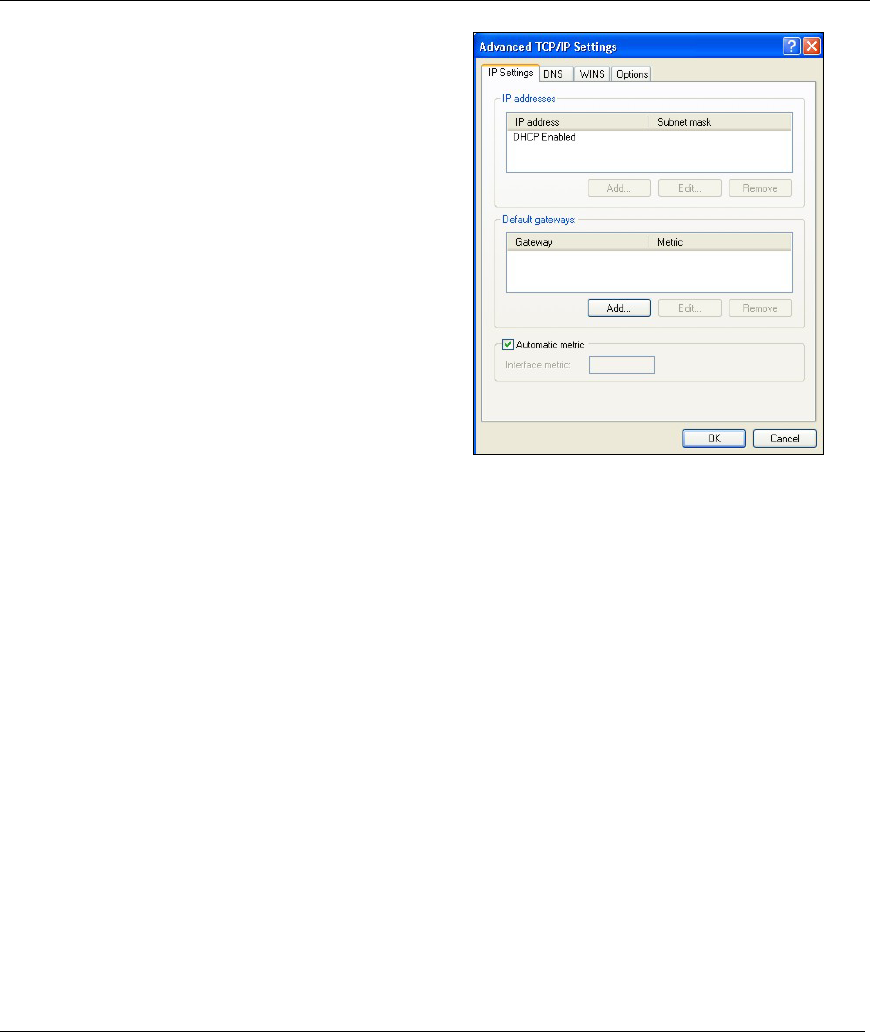
ZyAIR B-500 Wireless Access Point User’s Guide
Setting Up Your Computer’s IP Address C-7
6. -If you do not know your gateway's IP address,
remove any previously installed gateways in the
IP Settings tab and click OK.
Do one or more of the following if you want to
configure additional IP addresses:
-In the IP Settings tab, in IP addresses, click
Add.
-In TCP/IP Address, type an IP address in IP
address and a subnet mask in Subnet mask,
and then click Add.
-Repeat the above two steps for each IP address
you want to add.
-Configure additional default gateways in the IP
Settings tab by clicking Add in Default
gateways.
-In TCP/IP Gateway Address, type the IP
address of the default gateway in Gateway. To
manually configure a default metric (the number
of transmission hops), clear the Automatic
metric check box and type a metric in Metric.
-Click Add.
-Repeat the previous three steps for each default gateway you want to add.
-Click OK when finished.
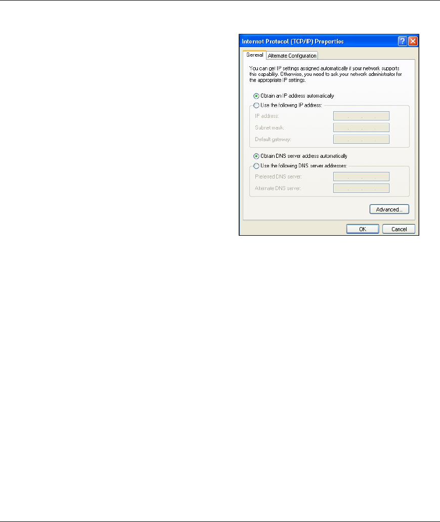
ZyAIR B-500 Wireless Access Point User’s Guide
C-8 Setting Up Your Computer’s IP Address
7. In the Internet Protocol TCP/IP Properties
window (the General tab in Windows XP):
-Click Obtain DNS server address
automatically if you do not know your DNS
server IP address(es).
-If you know your DNS server IP address(es),
click Use the following DNS server addresses,
and type them in the Preferred DNS server and
Alternate DNS server fields.
If you have previously configured DNS servers,
click Advanced and then the DNS tab to order
them.
8. Click OK to close the Internet Protocol (TCP/IP) Properties window.
9. Click OK to close the Local Area Connection Properties window.
10. Turn on your ZyAIR and restart your computer (if prompted).
Verifying Your Computer’s IP Address
1. Click Start, All Programs, Accessories and then Command Prompt.
2. In the Command Prompt window, type "ipconfig" and then press [ENTER]. You can also open
Network Connections, right-click a network connection, click Status and then click the Support tab.
Macintosh OS 8/9
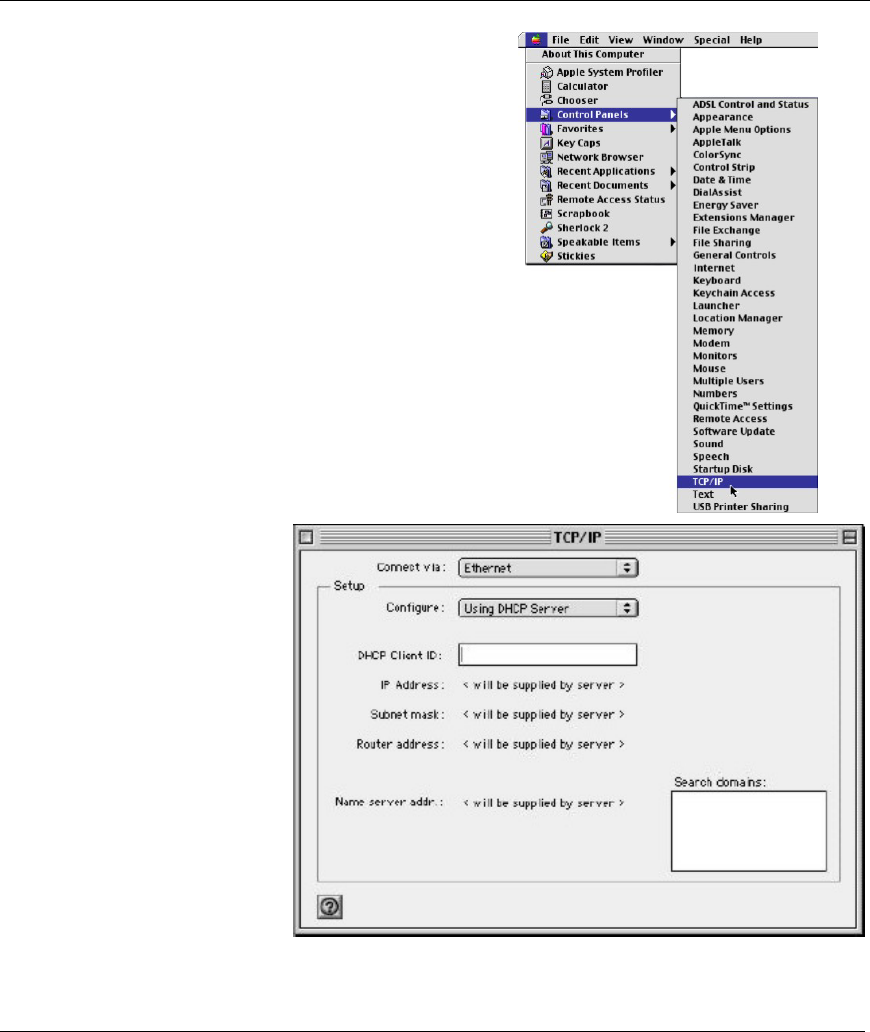
ZyAIR B-500 Wireless Access Point User’s Guide
Setting Up Your Computer’s IP Address C-9
1. Click the Apple menu, Control Panel and double-click
TCP/IP to open the TCP/IP Control Panel.
2. Select Ethernet built-in
from the Connect via list.
3. For dynamically assigned settings, select Using DHCP Server from the Configure: list.
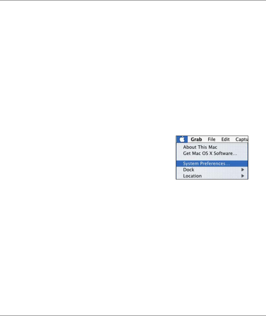
ZyAIR B-500 Wireless Access Point User’s Guide
C-10 Setting Up Your Computer’s IP Address
4. For statically assigned settings, do the following:
-From the Configure box, select Manually.
-Type your IP address in the IP Address box.
-Type your subnet mask in the Subnet mask box.
-Type the IP address of your ZyAIR in the Router address box.
5. Close the TCP/IP Control Panel.
6. Click Save if prompted, to save changes to your configuration.
7. Turn on your ZyAIR and restart your computer (if prompted).
Verifying Your Computer’s IP Address
Check your TCP/IP properties in the TCP/IP Control Panel window.
Macintosh OS X
1. Click the Apple menu, and click System Preferences
to open the System Preferences window.
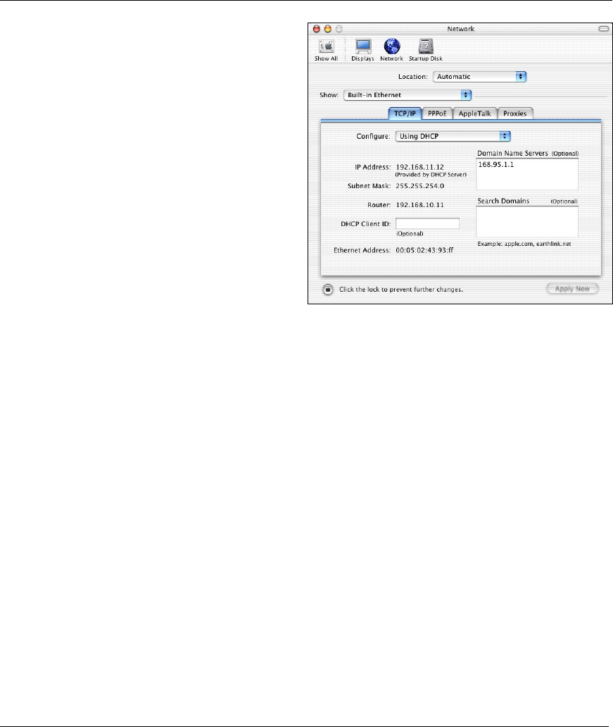
ZyAIR B-500 Wireless Access Point User’s Guide
Setting Up Your Computer’s IP Address C-11
2. Click Network in the icon bar.
- Select Automatic from the Location list.
- Select Built-in Ethernet from the Show list.
- Click the TCP/IP tab.
3. For dynamically assigned settings, select Using DHCP from the Configure list.
4. For statically assigned settings, do the following:
-From the Configure box, select Manually.
-Type your IP address in the IP Address box.
-Type your subnet mask in the Subnet mask box.
-Type the IP address of your ZyAIR in the Router address box.
5. Click Apply Now and close the window.
6. Turn on your ZyAIR and restart your computer (if prompted).
Verifying Your Computer’s IP Address
Check your TCP/IP properties in the Network window.

ZyAIR B-500 Wireless Access Point User’s Guide
Wireless LAN and IEEE 802.11 D-1
Appendix D
Wireless LAN and IEEE 802.11
A wireless LAN (WLAN) provides a flexible data communications system that you can use to access
various services (navigating the Internet, email, printer services, etc.) without the use of a cabled
connection. In effect a wireless LAN environment provides you the freedom to stay connected to the
network while roaming around in the coverage area. WLAN is not available on all models.
Benefits of a Wireless LAN
Wireless LAN offers the following benefits:
1. It provides you with access to network services in areas otherwise hard or expensive to wire, such as
historical buildings, buildings with asbestos materials and classrooms.
2. It provides healthcare workers like doctors and nurses access to a complete patient’s profile on a
handheld or notebook computer upon entering a patient’s room.
3. It allows flexible workgroups a lower total cost of ownership for workspaces that are frequently
reconfigured.
4. It allows conference room users access to the network as they move from meeting to meeting, getting
up-to-date access to information and the ability to communicate decisions while “on the go”.
5. It provides campus-wide networking mobility, allowing enterprises the roaming capability to set up
easy-to-use wireless networks that cover the entire campus transparently.
IEEE 802.11
The 1997 completion of the IEEE 802.11 standard for wireless LANs (WLANs) was a first important step
in the evolutionary development of wireless networking technologies. The standard was developed to
maximize interoperability between differing brands of wireless LANs as well as to introduce a variety of
performance improvements and benefits.
The IEEE 802.11 specifies three different transmission methods for the PHY, the layer responsible for
transferring data between nodes. Two of the methods use spread spectrum RF signals, Direct Sequence
Spread Spectrum (DSSS) and Frequency-Hopping Spread Spectrum (FHSS), in the 2.4 to 2.4825 GHz
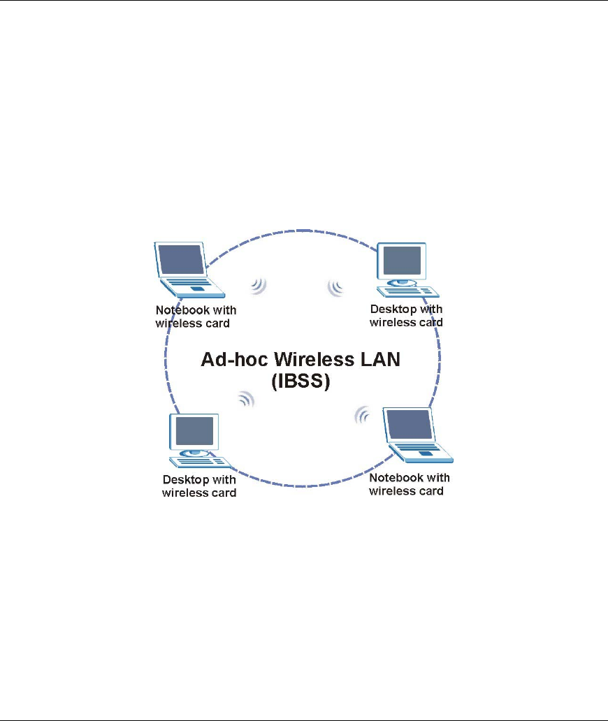
ZyAIR B-500 Wireless Access Point User’s Guide
D-2 Wireless LAN and IEEE 802.11
unlicensed ISM (Industrial, Scientific and Medical) band. The third method is infrared technology, using
very high frequencies, just below visible light in the electromagnetic spectrum to carry data.
Ad-hoc Wireless LAN Configuration
The simplest WLAN configuration is an independent (Ad-hoc) WLAN that connects a set of computers
with wireless nodes or stations (STA), which is called a Basic Service Set (BSS). In the most basic form, a
wireless LAN connects a set of computers with wireless adapters. Any time two or more wireless adapters
are within range of each other, they can set up an independent network, which is commonly referred to as
an Ad-hoc network or Independent Basic Service Set (IBSS). See the following diagram of an example of
an Ad-hoc wireless LAN.
Diagram D-1 Peer-to-Peer Communication in an Ad-hoc Network
Infrastructure Wireless LAN Configuration
For infrastructure WLANs, multiple access points (APs) link the WLAN to the wired network and allow
users to efficiently share network resources. The access points not only provide communication with the
wired network but also mediate wireless network traffic in the immediate neighborhood. Multiple access
points can provide wireless coverage for an entire building or campus. All communications between
stations or between a station and a wired network client go through the access point.
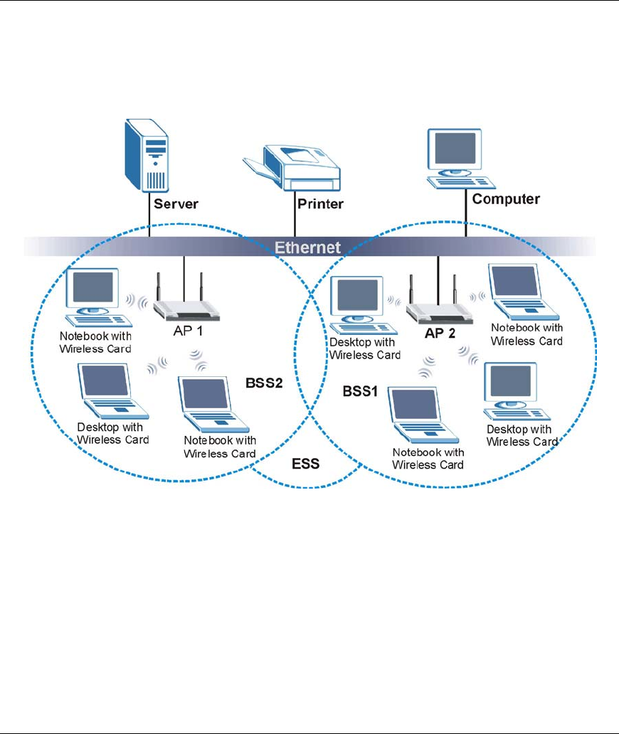
ZyAIR B-500 Wireless Access Point User’s Guide
Wireless LAN and IEEE 802.11 D-3
The Extended Service Set (ESS) shown in the next figure consists of a series of overlapping BSSs (each
containing an Access Point) connected together by means of a Distribution System (DS). Although the DS
could be any type of network, it is almost invariably an Ethernet LAN. Mobile nodes can roam between
access points and seamless campus-wide coverage is possible.
Diagram D-2 ESS Provides Campus-Wide Coverage

ZyAIR B-500 Wireless Access Point User’s Guide
Wireless LAN with IEEE 802.1x E-1
Appendix E
Wireless LAN With IEEE 802.1x
As wireless networks become popular for both portable computing and corporate networks, security is now
a priority.
Security Flaws with IEEE 802.11
Wireless networks based on the original IEEE 802.11 have a poor reputation for safety. The IEEE 802.11b
wireless access standard, first published in 1999, was based on the MAC address. As the MAC address is
sent across the wireless link in clear text, it is easy to spoof and fake. Even the WEP (Wire Equivalent
Privacy) data encryption is unreliable as it can be easily decrypted with current computer speed
Deployment Issues with IEEE 802.11
User account management has become a network administrator’s nightmare in a corporate environment, as
the IEEE 802.11b standard does not provide any central user account management. User access control is
done through manual modification of the MAC address table on the access point. Although WEP data
encryption offers a form of data security, you have to reset the WEP key on the clients each time you
change your WEP key on the access point.
IEEE 802.1x
In June 2001, the IEEE 802.1x standard was designed to extend the features of IEEE 802.11 to support
extended authentication as well as providing additional accounting and control features. It is supported by
Windows XP and a number of network devices.
Advantages of the IEEE 802.1x
• User based identification that allows for roaming.
• Support for RADIUS (Remote Authentication Dial In User Service, RFC 2138, 2139) for
centralized user profile and accounting management on a network RADIUS server.
• Support for EAP (Extensible Authentication Protocol, RFC 2486) that allows additional
authentication methods to be deployed with no changes to the access point or the wireless stations.
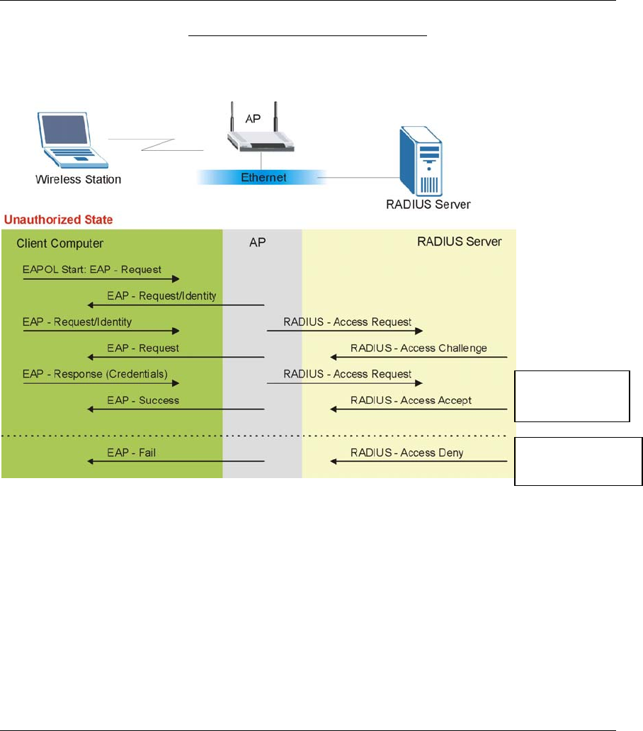
ZyAIR B-500 Wireless Access Point User’s Guide
E-2 Wireless LAN with IEEE 802.1x
RADIUS Server Authentication Sequence
The following figure depicts a typical wireless network with a remote RADIUS server for user
authentication using EAPOL (EAP Over LAN).
Diagram E-1 Sequences for EAP MD5–Challenge Authentication
Client computer
access authorized.
Client computer
access not authorized.

ZyAIR B-500 Wireless Access Point User’s Guide
Types of EAP Authentication F-1
Appendix F
Types of EAP Authentication
This appendix discusses the four popular EAP authentication types: EAP-MD5, EAP-TLS, EAP-TTLS
and PEAP. The type of authentication you use depends on the RADIUS server or the AP. Consult your
network administrator for more information.
EAP-MD5 (Message-Digest Algorithm 5)
MD5 authentication is the simplest one-way authentication method. The authentication server sends a
challenge to the wireless station. The wireless station ‘proves’ that it knows the password by encrypting the
password with the challenge and sends back the information. Password is not sent in plain text.
However, MD5 authentication has some weaknesses. Since the authentication server needs to get the
plaintext passwords, the passwords must be stored. Thus someone other than the authentication server may
access the password file. In addition, it is possible to impersonate an authentication server as MD5
authentication method does not perform mutual authentication. Finally, MD5 authentication method does
not support data encryption with dynamic session key. You must configure WEP encryption keys for data
encryption.
EAP-TLS (Transport Layer Security)
With EAP-TLS, digital certifications are needed by both the server and the wireless stations for mutual
authentication. The server presents a certificate to the client. After validating the identity of the server, the
client sends a different certificate to the server. The exchange of certificates is done in the open before a
secured tunnel is created. This makes user identity vulnerable to passive attacks. A digital certificate is an
electronic ID card that authenticates the sender’s identity. However, to implement EAP-TLS, you need a
Certificate Authority (CA) to handle certificates, which imposes a management overhead.
EAP-TTLS (Tunneled Transport Layer Service)
EAP-TTLS is an extension of the EAP-TLS authentication that uses certificates for only the server-side
authentications to establish a secure connection. Client authentication is then done by sending username
and password through the secure connection, thus client identity is protected. For client authentication,
EAP-TTLS supports EAP methods and legacy authentication methods such as PAP, CHAP, MS-CHAP and
MS-CHAP v2.
PEAP (Protected EAP)
Like EAP-TTLS, server-side certificate authentication is used to establish a secure connection, then use
simple username and password methods through the secured connection to authenticate the clients, thus

ZyAIR B-500 Wireless Access Point User’s Guide
F-2 Types of EAP Authentication
hiding client identity. However, PEAP only supports EAP methods, such as EAP-MD5 and EAP-
MSCHAPv2, for client authentication.
For added security, certificate-based authentications (EAP-TLS, EAP-TTLS and PEAP) use dynamic keys
for data encryption. They are often deployed in corporate environments, but for public deployment, simple
user name and password pair is more practical. The following table is a comparison of the features of four
authentication types.
Comparison of EAP Authentication Types
EAP-MD5 EAP-TLS EAP-TTLS PEAP
Mutual
Authentication
No Yes Yes Yes
Certificate – Client No Yes Optional Optional
Certificate – Server No Yes Yes Yes
Dynamic Key
Exchange
No Yes Yes Yes
Credential Security None Strong Strong Strong
Deployment
Difficulty
Easy Hard Moderate Moderate
Wireless Security Poor Best Good Good
Client Identity
Protection
No No Yes Yes

ZyAIR B-500 Wireless Access Point User’s Guide
IP Subnetting G-1
Appendix G
IP Subnetting
IP Addressing
Routers “route” based on the network number. The router that delivers the data packet to the correct
destination host uses the host ID.
IP Classes
An IP address is made up of four octets (eight bits), written in dotted decimal notation, for example,
192.168.1.1. IP addresses are categorized into different classes. The class of an address depends on the
value of its first octet.
Class “A” addresses have a 0 in the left most bit. In a class “A” address the first octet is the network
number and the remaining three octets make up the host ID.
Class “B” addresses have a 1 in the left most bit and a 0 in the next left most bit. In a class “B” address
the first two octets make up the network number and the two remaining octets make up the host ID.
Class “C” addresses begin (starting from the left) with 1 1 0. In a class “C” address the first three
octets make up the network number and the last octet is the host ID.
Class “D” addresses begin with 1 1 1 0. Class “D” addresses are used for multicasting. (There is also a
class “E” address. It is reserved for future use.)
Chart G-1 Classes of IP Addresses
IP ADDRESS: OCTET 1 OCTET 2 OCTET 3 OCTET 4
Class A 0 Network number Host ID Host ID Host ID
Class B 10 Network number Network number Host ID Host ID
Class C 110 Network number Network number Network number Host ID
Host IDs of all zeros or all ones are not allowed.
Therefore:
A class “C” network (8 host bits) can have 28 –2 or 254 hosts.
A class “B” address (16 host bits) can have 216 –2 or 65534 hosts.

ZyAIR B-500 Wireless Access Point User’s Guide
G-2 IP Subnetting
A class “A” address (24 host bits) can have 224 –2 hosts (approximately 16 million hosts).
Since the first octet of a class “A” IP address must contain a “0”, the first octet of a class “A” address can
have a value of 0 to 127.
Similarly the first octet of a class “B” must begin with “10”, therefore the first octet of a class “B” address
has a valid range of 128 to 191. The first octet of a class “C” address begins with “110”, and therefore has a
range of 192 to 223.
Chart G-2 Allowed IP Address Range By Class
CLASS ALLOWED RANGE OF FIRST OCTET
(BINARY)
ALLOWED RANGE OF FIRST OCTET
(DECIMAL)
Class A 00000000 to 01111111 0 to 127
Class B 10000000 to 10111111 128 to 191
Class C 11000000 to 11011111 192 to 223
Class D 11100000 to 11101111 224 to 239
Subnet Masks
A subnet mask is used to determine which bits are part of the network number, and which bits are part of
the host ID (using a logical AND operation). A subnet mask has 32 bits; each bit of the mask corresponds
to a bit of the IP address. If a bit in the subnet mask is a “1” then the corresponding bit in the IP address is
part of the network number. If a bit in the subnet mask is “0” then the corresponding bit in the IP address is
part of the host ID.
Subnet masks are expressed in dotted decimal notation just as IP addresses are. The “natural” masks for
class A, B and C IP addresses are as follows.
Chart G-3 “Natural” Masks
CLASS NATURAL MASK
A 255.0.0.0
B 255.255.0.0
C 255.255.255.0
Subnetting
With subnetting, the class arrangement of an IP address is ignored. For example, a class C address no
longer has to have 24 bits of network number and 8 bits of host ID. With subnetting, some of the host ID
bits are converted into network number bits. By convention, subnet masks always consist of a continuous

ZyAIR B-500 Wireless Access Point User’s Guide
IP Subnetting G-3
sequence of ones beginning from the left most bit of the mask, followed by a continuous sequence of zeros,
for a total number of 32 bits.
Since the mask is always a continuous number of ones beginning from the left, followed by a continuous
number of zeros for the remainder of the 32 bit mask, you can simply specify the number of ones instead of
writing the value of each octet. This is usually specified by writing a “/” followed by the number of bits in
the mask after the address.
For example, 192.1.1.0 /25 is equivalent to saying 192.1.1.0 with mask 255.255.255.128.
The following table shows all possible subnet masks for a class “C” address using both notations.
Chart G-4 Alternative Subnet Mask Notation
SUBNET MASK IP ADDRESS SUBNET MASK “1” BITS LAST OCTET BIT VALUE
255.255.255.0 /24 0000 0000
255.255.255.128 /25 1000 0000
255.255.255.192 /26 1100 0000
255.255.255.224 /27 1110 0000
255.255.255.240 /28 1111 0000
255.255.255.248 /29 1111 1000
255.255.255.252 /30 1111 1100
The first mask shown is the class “C” natural mask. Normally if no mask is specified it is understood that
the natural mask is being used.
Example: Two Subnets
As an example, you have a class “C” address 192.168.1.0 with subnet mask of 255.255.255.0.
NETWORK NUMBER HOST ID
IP Address 192.168.1. 0
IP Address (Binary) 11000000.10101000.00000001. 00000000
Subnet Mask 255.255.255. 0
Subnet Mask (Binary) 11111111.11111111.11111111. 00000000
The first three octets of the address make up the network number (class “C”). You want to have two
separate networks.

ZyAIR B-500 Wireless Access Point User’s Guide
G-4 IP Subnetting
Divide the network 192.168.1.0 into two separate subnets by converting one of the host ID bits of the IP
address to a network number bit. The “borrowed” host ID bit can be either “0” or “1” thus giving two
subnets; 192.168.1.0 with mask 255.255.255.128 and 192.168.1.128 with mask 255.255.255.128.
In the following charts, shaded/bolded last octet bit values indicate host ID bits
“borrowed” to form network ID bits. The number of “borrowed” host ID bits
determines the number of subnets you can have. The remaining number of host
ID bits (after “borrowing”) determines the number of hosts you can have on each
subnet.
Chart G-5 Subnet 1
NETWORK NUMBER LAST OCTET BIT VALUE
IP Address 192.168.1. 0
IP Address (Binary) 11000000.10101000.00000001. 00000000
Subnet Mask 255.255.255. 128
Subnet Mask (Binary) 11111111.11111111.11111111. 10000000
Subnet Address: 192.168.1.0 Lowest Host ID: 192.168.1.1
Broadcast Address: 192.168.1.127 Highest Host ID: 192.168.1.126
Chart G-6 Subnet 2
NETWORK NUMBER LAST OCTET BIT VALUE
IP Address 192.168.1. 128
IP Address (Binary) 11000000.10101000.00000001. 10000000
Subnet Mask 255.255.255. 128
Subnet Mask (Binary) 11111111.11111111.11111111. 10000000
Subnet Address: 192.168.1.128 Lowest Host ID: 192.168.1.129
Broadcast Address: 192.168.1.255 Highest Host ID: 192.168.1.254
The remaining 7 bits determine the number of hosts each subnet can have. Host IDs of all zeros represent
the subnet itself and host IDs of all ones are the broadcast address for that subnet, so the actual number of
hosts available on each subnet in the example above is 27 – 2 or 126 hosts for each subnet.
192.168.1.0 with mask 255.255.255.128 is the subnet itself, and 192.168.1.127 with mask 255.255.255.128
is the directed broadcast address for the first subnet. Therefore, the lowest IP address that can be assigned
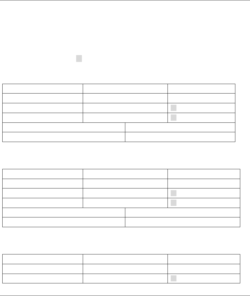
ZyAIR B-500 Wireless Access Point User’s Guide
IP Subnetting G-5
to an actual host for the first subnet is 192.168.1.1 and the highest is 192.168.1.126. Similarly the host ID
range for the second subnet is 192.168.1.129 to 192.168.1.254.
Example: Four Subnets
The above example illustrated using a 25-bit subnet mask to divide a class “C” address space into two
subnets. Similarly to divide a class “C” address into four subnets, you need to “borrow” two host ID bits to
give four possible combinations of 00, 01, 10 and 11. The subnet mask is 26 bits
(11111111.11111111.11111111.11000000) or 255.255.255.192. Each subnet contains 6 host ID bits, giving
26-2 or 62 hosts for each subnet (all 0’s is the subnet itself, all 1’s is the broadcast address on the subnet).
Chart G-7 Subnet 1
NETWORK NUMBER LAST OCTET BIT VALUE
IP Address 192.168.1. 0
IP Address (Binary) 11000000.10101000.00000001. 00000000
Subnet Mask (Binary) 11111111.11111111.11111111. 11000000
Subnet Address: 192.168.1.0 Lowest Host ID: 192.168.1.1
Broadcast Address: 192.168.1.63 Highest Host ID: 192.168.1.62
Chart G-8 Subnet 2
NETWORK NUMBER LAST OCTET BIT VALUE
IP Address 192.168.1. 64
IP Address (Binary) 11000000.10101000.00000001. 01000000
Subnet Mask (Binary) 11111111.11111111.11111111. 11000000
Subnet Address: 192.168.1.64 Lowest Host ID: 192.168.1.65
Broadcast Address: 192.168.1.127 Highest Host ID: 192.168.1.126
Chart G-9 Subnet 3
NETWORK NUMBER LAST OCTET BIT VALUE
IP Address 192.168.1. 128
IP Address (Binary) 11000000.10101000.00000001. 10000000
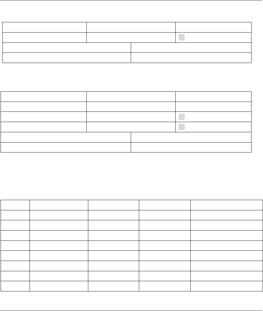
ZyAIR B-500 Wireless Access Point User’s Guide
G-6 IP Subnetting
Chart G-9 Subnet 3
NETWORK NUMBER LAST OCTET BIT VALUE
Subnet Mask (Binary) 11111111.11111111.11111111. 11000000
Subnet Address: 192.168.1.128 Lowest Host ID: 192.168.1.129
Broadcast Address: 192.168.1.191 Highest Host ID: 192.168.1.190
Chart G-10 Subnet 4
NETWORK NUMBER LAST OCTET BIT VALUE
IP Address 192.168.1. 192
IP Address (Binary) 11000000.10101000.00000001. 11000000
Subnet Mask (Binary) 11111111.11111111.11111111. 11000000
Subnet Address: 192.168.1.192 Lowest Host ID: 192.168.1.193
Broadcast Address: 192.168.1.255 Highest Host ID: 192.168.1.254
Example Eight Subnets
Similarly use a 27-bit mask to create 8 subnets (001, 010, 011, 100, 101, 110).
The following table shows class C IP address last octet values for each subnet.
Chart G-11 Eight Subnets
SUBNET SUBNET ADDRESS FIRST ADDRESS LAST ADDRESS BROADCAST ADDRESS
1 0 1 30 31
2 32 33 62 63
3 64 65 94 95
4 96 97 126 127
5 128 129 158 159
6 160 161 190 191
7 192 193 222 223
8 224 223 254 255

ZyAIR B-500 Wireless Access Point User’s Guide
IP Subnetting G-7
The following table is a summary for class “C” subnet planning.
Chart G-12 Class C Subnet Planning
NO. “BORROWED” HOST BITS SUBNET MASK NO. SUBNETS NO. HOSTS PER
SUBNET
1 255.255.255.128 (/25) 2 126
2 255.255.255.192 (/26) 4 62
3 255.255.255.224 (/27) 8 30
4 255.255.255.240 (/28) 16 14
5 255.255.255.248 (/29) 32 6
6 255.255.255.252 (/30) 64 2
7 255.255.255.254 (/31) 128 1
Subnetting With Class A and Class B Networks.
For class “A” and class “B” addresses the subnet mask also determines which bits are part of the network
number and which are part of the host ID.
A class “B” address has two host ID octets available for subnetting and a class “A” address has three host
ID octets (see Chart J-1) available for subnetting.
The following table is a summary for class “B” subnet planning.
Chart G-13 Class B Subnet Planning
NO. “BORROWED” HOST BITS SUBNET MASK NO. SUBNETS NO. HOSTS PER SUBNET
1 255.255.128.0 (/17) 2 32766
2 255.255.192.0 (/18) 4 16382
3 255.255.224.0 (/19) 8 8190
4 255.255.240.0 (/20) 16 4094
5 255.255.248.0 (/21) 32 2046
6 255.255.252.0 (/22) 64 1022
7 255.255.254.0 (/23) 128 510
8 255.255.255.0 (/24) 256 254

ZyAIR B-500 Wireless Access Point User’s Guide
G-8 IP Subnetting
Chart G-13 Class B Subnet Planning
NO. “BORROWED” HOST BITS SUBNET MASK NO. SUBNETS NO. HOSTS PER SUBNET
9 255.255.255.128
(/25)
512 126
10 255.255.255.192
(/26)
1024 62
11 255.255.255.224
(/27)
2048 30
12 255.255.255.240
(/28)
4096 14
13 255.255.255.248
(/29)
8192 6
14 255.255.255.252
(/30)
16384 2
15 255.255.255.254
(/31)
32768 1

ZyAIR B-500 Wireless Access Point User’s Guide
Command Interpreter H-1
Appendix H
Command Interpreter
The following describes how to use the command interpreter. Enter 24 in the main menu to bring up the
system maintenance menu. Enter 8 to go to Menu 24.8 - Command Interpreter Mode. See the included
disk or www.zyxel.com for more detailed information on these commands.
Use of undocumented commands or misconfiguration can damage the unit and
possibly render it unusable.
Command Syntax
The command keywords are in courier new font.
Enter the command keywords exactly as shown, do not abbreviate.
The required fields in a command are enclosed in angle brackets <>.
The optional fields in a command are enclosed in square brackets [].
The |symbol means “or”.
For example,
sys filter netbios config <type> <on|off>
means that you must specify the type of netbios filter and whether to turn it on or off.
Command Usage
A list of valid commands can be found by typing help or ? at the command prompt. Always type the full
command. Type exit to return to the SMT main menu when finished.

ZyAIR B-500 Wireless Access Point User’s Guide
Log Description I-1
Appendix I
Log Descriptions
Chart I-1 System Maintenance Logs
LOG MESSAGE DESCRIPTION
Time calibration is
successful
The ZyAIR has adjusted its time based on information from the time
server.
Time calibration
failed
The ZyAIR failed to get information from the time server.
DHCP client gets %s A DHCP client got a new IP address from the DHCP server.
DHCP client IP
expired
A DHCP client's IP address has expired.
DHCP server assigns
%s
The DHCP server assigned an IP address to a client.
SMT Login
Successfully
Someone has logged on to the ZyAIR 's SMT interface.
SMT Login Fail Someone has failed to log on to the ZyAIR s SMT interface.
WEB Login
Successfully
Someone has logged on to the ZyAIR 's web configurator interface.
WEB Login Fail Someone has failed to log on to the ZyAIR 's web configurator
interface.
TELNET Login
Successfully
Someone has logged on to the ZyAIR via telnet.
TELNET Login Fail Someone has failed to log on to the ZyAIR via telnet.
FTP Login
Successfully
Someone has logged on to the ZyAIR via FTP.
FTP Login Fail Someone has failed to log on to the ZyAIR via FTP.

ZyAIR B-500 Wireless Access Point User’s Guide
I-2 Log Descriptions
Chart I-2 ICMP Notes
TYPE CODE DESCRIPTION
0
Echo Reply
0
Echo reply message
3
Destination Unreachable
0
Net unreachable
1
Host unreachable
2
Protocol unreachable
3
Port unreachable
4
A packet that needed fragmentation was dropped because it was set to Don't
Fragment (DF)
5
Source route failed
4
Source Quench
0
A gateway may discard internet datagrams if it does not have the buffer space
needed to queue the datagrams for output to the next network on the route to
the destination network.
5
Redirect
0
Redirect datagrams for the Network
1
Redirect datagrams for the Host
2
Redirect datagrams for the Type of Service and Network
3
Redirect datagrams for the Type of Service and Host
8
Echo
0
Echo message
11
Time Exceeded
0
Time to live exceeded in transit
1
Fragment reassembly time exceeded
12
Parameter Problem
0
Pointer indicates the error

ZyAIR B-500 Wireless Access Point User’s Guide
Log Description I-3
Chart I-2 ICMP Notes
TYPE CODE DESCRIPTION
13
Timestamp
0
Timestamp request message
14
Timestamp Reply
0
Timestamp reply message
15
Information Request
0
Information request message
16
Information Reply
0
Information reply message
Chart I-3 Sys log
LOG MESSAGE DESCRIPTION
Mon dd hr:mm:ss hostname
src="<srcIP:srcPort>"
dst="<dstIP:dstPort>"
msg="<msg>" note="<note>"
This message is sent by the "RAS" when this syslog is
generated. The messages and notes are defined in this
appendix’s other charts.
Log Commands
Go to the command interpreter interface (the Command Interpreter Appendix explains how to access and
use the commands).
Configuring What You Want the ZyAIR to Log
Use the sys logs load command to load the log setting buffer that allows you to configure which logs
the ZyAIR is to record.
Use sys logs category followed by a log category and a parameter to decide what to record

ZyAIR B-500 Wireless Access Point User’s Guide
I-4 Log Descriptions
Chart I-4 Log Categories and Available Settings
LOG CATEGORIES AVAILABLE PARAMETERS
8021x 0, 1
access 0, 1, 2, 3
error 0, 1, 2, 3
icmp 0, 1
mten 0, 1
packetfilter 0, 1
remote 0, 1
tcpreset 0, 1
Use 0 to not record logs for that category, 1 to record only logs for that category, 2 to record only
alerts for that category, and 3 to record both logs and alerts for that category.
Use the sys logs save command to store the settings in the ZyAIR (you must do this in order to
record logs).
Displaying Logs
Use the sys logs display command to show all of the logs in the ZyAIR’s log.
Use the sys logs category display command to show the log settings for all of the log
categories.
Use the sys logs display [log category] command to show the logs in an individual ZyAIR
log category.
Use the sys logs clear command to erase all of the ZyAIR’s logs.
Log Command Example
This example shows how to set the ZyAIR to record the error logs and alerts and then view the results.
ras> sys logs load
ras> sys logs category error 3
ras> sys logs save
ras> sys logs display access

ZyAIR B-500 Wireless Access Point User’s Guide
Log Description I-5
# .time source destination
notes
message
0|11/11/2002 15:10:12 |172.22.3.80:137 |172.22.255.255:137
|ACCESS BLOCK

ZyAIR B-500 Wireless Access Point User’s Guide
Index J-1
Appendix J
Index
A
Address Assignment.........................................3-5, 7-1
Ad-hoc Configuration.............................................D-2
Alternative Subnet Mask Notation ......................... G-3
Applications ............................................................1-4
auto-negotiation.......................................................1-1
B
backup ...................................................................17-2
Backup.....................................................................9-8
Basic Service Set....................................................D-2
BSS............................................. See Basic Service Set
C
CA ...........................................................................F-1
Certificate Authority......................................... See CA
Channel ID .....................................................5-6, 12-3
Classes of IP Addresses.......................................... G-1
Collision ................................................................16-2
Command Interpreter ............................................18-1
Community............................................................14-2
Computer’s IP Address .......................................... C-1
Copyright....................................................................ii
CPU Load..............................................................16-3
Customer Support....................................................... v
D
Data encryption .......................................................3-1
Default...................................................................9-11
DHCP ....................................................................16-4
Diagnostic .............................................................16-6
Diagnostic Tools ...................................................16-1
Direct Sequence Spread Spectrum..........................D-2
Distribution System................................................D-3
DS...........................................See Distribution System
DSSS ............... See Direct Sequence Spread Spectrum
E
EAP ........................................................................ 1-3
EAP Authentication ................................................ F-1
MD5 ................................................................... F-1
TLS..................................................................... F-1
TTLS .................................................................. F-1
Error Log .............................................................. 16-5
Error/Information Messages
Sample.............................................................. 16-5
ESS .. See Extended Service Set. See Extended Service
Set
ESS ID.................................................................... 3-1
Extended Service Set ...................................... D-3, 5-2
Extended Service Set IDentification ....................... 5-6
F
FCC .......................................................................... iii
FHSS ......... See Frequency-Hopping Spread Spectrum
Filename Conventions .......................................... 17-1
Firmware File
Maintenance................................................ 9-6, 9-8
Fragment Threshold.............................................. 12-3
Fragmentation Threshold........................................ 5-4
Frequency-Hopping Spread Spectrum ....................D-2
FTP File Transfer.................................................. 17-7
G
General Setup ......................................... 3-2, 4-1, 11-1
H
Hidden Menus....................................................... 10-4
Host ........................................................................ 4-3

ZyAIR B-500 Wireless Access Point User’s Guide
J-2 Index
Host IDs..................................................................G-1
I
IBSS....................... See Independent Basic Service Set
IEEE 802.11 ...........................................................D-1
Deployment Issues ............................................. E-1
Security Flaws.................................................... E-1
IEEE 802.1x ....................................................E-1, 1-3
Advantages......................................................... E-1
Independent Basic Service Set................. D-2, 5-1, 9-5
Infrastructure Configuration ...................................D-2
Internet access........................................................12-1
Internet Access ................................................ 1-4, 1-5
Internet Security Gateway .......................................1-1
IP Address .................... 3-5, 7-1, 7-2, 12-2, 16-4, 16-6
IP Addressing .........................................................G-1
IP Classes................................................................G-1
L
Link type................................................................16-2
Log and Trace........................................................16-5
Log Descriptions......................................................J-1
Logs .........................................................................8-1
M
MAC Address Filter Action........................... 6-6, 12-6
MAC Address Filtering .........................................12-5
Main Menu ............................................................10-4
Management Information Base (MIB)...................14-2
MD5........................................................................ F-1
Message Digest Algorithm 5 .........................See MD5
N
Network Management .............................................1-3
Network Topology With RADIUS Server ExampleE-2
P
Packets...................................................................16-2
Password............................................... 4-2, 10-1, 14-2
Ping........................................................................16-6
Private IP Address............................................3-5, 7-1
Q
Quick Installation Guide .......................................... xv
R
RADIUS.................................................................. 1-3
RAS....................................................................... 16-4
Rate
Receiving.......................................................... 16-2
Transmission..................................................... 16-2
Related Documentation............................................ xv
Remote Authentication Dial In User Service ..........See
RADIUS
Remote Node ........................................................ 16-2
Required fields ...................................................... 10-4
Restore .................................................................... 9-9
Restore Configuration........................................... 17-5
RF signals .............................................................. D-1
Roaming
Example.............................................................. 5-7
Requirements...................................................... 5-8
RTS Threshold...............................................5-3, 12-3
S
Server...................................................................... 4-5
Service ...................................................................... iv
Service Set .............................................................. 5-6
SMT Menu Overview ........................................... 10-2
SNMP
Community ....................................................... 14-3
Configuration.................................................... 14-2
Get .................................................................... 14-2
GetNext ............................................................ 14-2
Manager............................................................ 14-2
MIBs................................................................. 14-2
Set..................................................................... 14-2
Trap .................................................................. 14-2
Traps........................................................ 14-3, 14-4
Trusted Host ..................................................... 14-3
Subnet Mask.................................. 3-5, 7-1, 12-2, 16-4
Subnet Masks ......................................................... G-2
Subnetting .............................................................. G-3

ZyAIR B-500 Wireless Access Point User’s Guide
Index J-3
Supporting Disk........................................................ xv
System
Console Port Speed....................................... 16-4
Diagnostic ...................................................... 16-5
Log and Trace................................................ 16-5
System Information...........................................16-3
System Status....................................................16-1
Time and Date...................................................18-2
System Information ...............................................16-3
System Information & Diagnosis ..........................16-1
System Maintenance..16-1, 16-3, 17-2, 17-4, 17-5, 17-
6, 17-9, 18-1, 18-2, 18-3
System Management Terminal..............................10-4
System Name...........................................................4-2
T
TCP/IP...................................................................16-6
TFTP File Transfer................................................17-9
Time and Date Setting...........................................18-2
Time Server...........................................................18-3
Time Zone .............................................................18-3
TLS..........................................................................F-1
Trace Records........................................................16-5
Transport Layer Security................................ See TLS
Troubleshooting
Accessing ZyAIR.......................................A-2, A-3
Ethernet Port ...................................................... A-1
Password ............................................................ A-2
Start-Up..............................................................A-1
TTLS....................................................................... F-1
Tunneled Transport Layer Service................See TTLS
U
Upload Firmware.................................................. 17-6
User Profiles .................................................. 6-9, 13-1
V
Valid CI Commands ............................................. 18-1
W
Web Configurator ............................................ 2-1, 2-3
WEP........................................................................ 3-1
WEP Encryption............................................ 6-4, 12-3
Wireless LAN............................................... D-1, 12-2
Benefits ..............................................................D-1
Wireless LAN Setup ............................................. 12-2
Wizard Setup .....................................3-1, 3-2, 3-3, 3-4
WLAN ............................................ See Wireless LAN
Z
ZyNOS......................................................... 17-1, 17-2
ZyNOS F/W Version ............................................ 17-1
ZyXEL Limited Warranty
Note.......................................................................iv