ZyXEL Communications B500 Wireless LAN Access Point User Manual P650H 17 ADSL Router User s Guide
ZyXEL Communications Corporation Wireless LAN Access Point P650H 17 ADSL Router User s Guide
Contents
- 1. Users Manual 1
- 2. Users Manual 2
Users Manual 1

ZyAIR B-500
Wireless Access Point
User's Guide
Version 3.50
November 2003
BETA DRAFT

ZyAIR B-500 Wireless Access Point User’s Guide
ii Copyright
Copyright
Copyright © 2003 by ZyXEL Communications Corporation.
The contents of this publication may not be reproduced in any part or as a whole, transcribed, stored in a
retrieval system, translated into any language, or transmitted in any form or by any means, electronic,
mechanical, magnetic, optical, chemical, photocopying, manual, or otherwise, without the prior written
permission of ZyXEL Communications Corporation.
Published by ZyXEL Communications Corporation. All rights reserved.
Disclaimer
ZyXEL does not assume any liability arising out of the application or use of any products, or software
described herein. Neither does it convey any license under its patent rights nor the patent rights of others.
ZyXEL further reserves the right to make changes in any products described herein without notice. This
publication is subject to change without notice.
Trademarks
ZyNOS (ZyXEL Network Operating System) is a registered trademark of ZyXEL Communications, Inc.
Other trademarks mentioned in this publication are used for identification purposes only and may be
properties of their respective owners.

ZyAIR B-500 Wireless Access Point User’s Guide
FCC Statement iii
Federal Communications Commission
(FCC) Interference Statement
This device complies with Part 15 of FCC rules. Operation is subject to the following two conditions:
• This device may not cause harmful interference.
• This device must accept any interference received, including interference that may cause undesired
operations.
This equipment has been tested and found to comply with the limits for a Class B digital device pursuant to
Part 15 of the FCC Rules. These limits are designed to provide reasonable protection against harmful
interference in a commercial environment. This equipment generates, uses, and can radiate radio frequency
energy, and if not installed and used in accordance with the instructions, may cause harmful interference to
radio communications.
If this equipment does cause harmful interference to radio/television reception, which can be determined by
turning the equipment off and on, the user is encouraged to try to correct the interference by one or more of
the following measures:
1. Reorient or relocate the receiving antenna.
2. Increase the separation between the equipment and the receiver.
3. Connect the equipment into an outlet on a circuit different from that to which the receiver is connected.
4. Consult the dealer or an experienced radio/TV technician for help.
Caution
1. To comply with FCC RF exposure compliance requirements, a separation distance of at least 20 cm
must be maintained between the antenna of this device and all persons.
2. This transmitter must not be co-located or operating in conjunction with any other antenna or
transmitter.
Notice 1
Changes or modifications not expressly approved by the party responsible for compliance could void the
user's authority to operate the equipment.
Certifications
Refer to the product page at www.zyxel.com.

ZyAIR B-500 Wireless Access Point User’s Guide
iv ZyXEL Warranty
ZyXEL Limited Warranty
ZyXEL warrants to the original end user (purchaser) that this product is free from any defects in materials
or workmanship for a period of up to two years from the date of purchase. During the warranty period, and
upon proof of purchase, should the product have indications of failure due to faulty workmanship and/or
materials, ZyXEL will, at its discretion, repair or replace the defective products or components without
charge for either parts or labor, and to whatever extent it shall deem necessary to restore the product or
components to proper operating condition. Any replacement will consist of a new or re-manufactured
functionally equivalent product of equal value, and will be solely at the discretion of ZyXEL. This warranty
shall not apply if the product is modified, misused, tampered with, damaged by an act of God, or subjected
to abnormal working conditions.
Note
Repair or replacement, as provided under this warranty, is the exclusive remedy of the purchaser. This
warranty is in lieu of all other warranties, express or implied, including any implied warranty of
merchantability or fitness for a particular use or purpose. ZyXEL shall in no event be held liable for indirect
or consequential damages of any kind of character to the purchaser.
To obtain the services of this warranty, contact ZyXEL's Service Center for your Return Material
Authorization number (RMA). Products must be returned Postage Prepaid. It is recommended that the unit
be insured when shipped. Any returned products without proof of purchase or those with an out-dated
warranty will be repaired or replaced (at the discretion of ZyXEL) and the customer will be billed for parts
and labor. All repaired or replaced products will be shipped by ZyXEL to the corresponding return address,
Postage Paid. This warranty gives you specific legal rights, and you may also have other rights that vary
from country to country.
Safety Warnings
1. To reduce the risk of fire, use only No. 26 AWG or larger telephone wire.
2. Do not use this product near water, for example, in a wet basement or near a swimming pool.
3. Avoid using this product during an electrical storm. There may be a remote risk of electric shock from
lightening.

ZyAIR B-500 Wireless Access Point User’s Guide
Customer Support v
Customer Support
Please have the following information ready when you contact customer support.
• Product model and serial number.
• Warranty Information.
• Date that you received your device.
• Brief description of the problem and the steps you took to solve it.
METHOD
LOCATION
E-MAIL
SUPPORT/SALES
TELEPHONE/FAX WEB SITE/ FTP SITE REGULAR MAIL
support@zyxel.com.tw
+886-3-578-3942 www.zyxel.com
www.europe.zyxel.com
ftp.zyxel.com
WORLDWIDE
sales@zyxel.com.tw +886-3-578-2439 ftp.europe.zyxel.com
ZyXEL Communications Corp.,
6 Innovation Road II, Science-
Based Industrial Park, Hsinchu
300, Taiwan.
support@zyxel.com +1-800-255-4101 www.us.zyxel.com NORTH
AMERICA
sales@zyxel.com +1-714-632-0858 ftp.us.zyxel.com
ZyXEL Communications Inc.,
1130 N. Miller St.
Anaheim, CA 92806, U.S.A.
support@zyxel.dk +45-3955-0700 www.zyxel.dk SCANDINAVIA
sales@zyxel.dk +45-3955-0707 ftp.zyxel.dk
ZyXEL Communications A/S,
Columbusvej 5, 2860 Soeborg,
Denmark.
support@zyxel.de +49-2405-6909-0 www.zyxel.de GERMANY
sales@zyxel.de +49-2405-6909-99
ZyXEL Deutschland GmbH.
Adenauerstr. 20/A2 D-52146
Wuerselen, Germany

ZyAIR B-500 Wireless Access Point User’s Guide
vi Table of Contents
Table of Contents
Copyright......................................................................................................................................................... ii
Federal Communications Commission (FCC) Interference Statement.....................................................iii
ZyXEL Limited Warranty ............................................................................................................................ iv
Customer Support........................................................................................................................................... v
List of Figures ................................................................................................................................................. x
List of Tables ................................................................................................................................................xiii
Preface ........................................................................................................................................................... xv
OVERVIEW.....................................................................................................................................................I
Chapter 1 Getting to Know Your ZyAIR...................................................................................................1-1
1.1 Introducing the ZyAIR Wireless Access Point ..........................................................................1-1
1.2 ZyAIR Features..........................................................................................................................1-1
1.3 Applications for the ZyAIR .......................................................................................................1-4
1.3.1 Internet Access Application ...............................................................................................1-4
1.3.2 Corporation Network Application......................................................................................1-4
Chapter 2 Introducing the Web Configurator ..........................................................................................2-1
2.1 Accessing the ZyAIR Web Configurator...................................................................................2-1
2.2 Resetting the ZyAIR ..................................................................................................................2-2
2.2.1 Method of Restoring Factory-Defaults ..............................................................................2-2
2.3 Navigating the ZyAIR Web Configurator..................................................................................2-3
Chapter 3 Wizard Setup..............................................................................................................................3-1
3.1 Wizard Setup Overview .............................................................................................................3-1
3.1.1 Channel ..............................................................................................................................3-1
3.1.2 ESS ID ...............................................................................................................................3-1
3.1.3 WEP Encryption ................................................................................................................3-1
3.2 Wizard Setup: General Setup.....................................................................................................3-2
3.3 Wizard Setup: Wireless LAN ....................................................................................................3-3
3.4 Wizard Setup: IP Address..........................................................................................................3-4
3.4.1 IP Address Assignment......................................................................................................3-5
3.4.2 IP Address and Subnet Mask .............................................................................................3-5
3.5 Basic Setup Complete ................................................................................................................3-7
SYSTEM, WIRELESS AND IP.................................................................................................................... II
Chapter 4 System Screens ...........................................................................................................................4-1
4.1 System Overview.......................................................................................................................4-1
4.2 Configuring General Setup ........................................................................................................4-1
4.3 Configuring Password................................................................................................................4-2
4.4 Configuring Time Setting ..........................................................................................................4-3
Chapter 5 Wireless Configuration and Roaming......................................................................................5-1
5.1 Wireless LAN Overview............................................................................................................5-1
5.1.1 IBSS...................................................................................................................................5-1

ZyAIR B-500 Wireless Access Point User’s Guide
Table of Contents vii
5.1.2 BSS.....................................................................................................................................5-1
5.1.3 ESS.....................................................................................................................................5-2
5.2 Wireless LAN Basics .................................................................................................................5-3
5.2.1 RTS/CTS............................................................................................................................5-3
5.2.2 Fragmentation Threshold ...................................................................................................5-4
5.3 Configuring Wireless .................................................................................................................5-5
5.4 Configuring Roaming.................................................................................................................5-6
5.4.1 Requirements for Roaming ................................................................................................5-8
Chapter 6 Wireless Security ........................................................................................................................6-1
6.1 Wireless Security Overview.......................................................................................................6-1
6.2 WEP Overview...........................................................................................................................6-1
6.2.1 Data Encryption .................................................................................................................6-1
6.2.2 Authentication ....................................................................................................................6-2
6.3 Configuring WEP Encryption ....................................................................................................6-3
6.4 MAC Filter.................................................................................................................................6-4
6.5 802.1x Overview........................................................................................................................6-6
6.6 Introduction to RADIUS ............................................................................................................6-6
6.6.1 EAP Authentication Overview...........................................................................................6-7
6.7 Dynamic WEP Key Exchange ...................................................................................................6-8
6.8 Introduction to Local User Database..........................................................................................6-9
6.9 Configuring 802.1x ....................................................................................................................6-9
6.10 Configuring Local User Database ............................................................................................6-11
6.11 Configuring RADIUS ..............................................................................................................6-13
Chapter 7 IP Screen .....................................................................................................................................7-1
7.1 Factory Ethernet Defaults...........................................................................................................7-1
7.2 TCP/IP Parameters .....................................................................................................................7-1
7.2.1 IP Address and Subnet Mask..............................................................................................7-1
7.3 Configuring IP............................................................................................................................7-1
LOGS ............................................................................................................................................................ III
Chapter 8 Logs Screens ...............................................................................................................................8-1
8.1 Configuring View Log ...............................................................................................................8-1
8.2 Configuring Log Settings ...........................................................................................................8-2
MAINTENANCE......................................................................................................................................... IV
Chapter 9 Maintenance ...............................................................................................................................9-1
9.1 Maintenance Overview ..............................................................................................................9-1
9.2 System Status Screen .................................................................................................................9-1
9.2.1 System Statistics.................................................................................................................9-2
9.3 Wireless Screen..........................................................................................................................9-3
9.3.1 Association List..................................................................................................................9-3
9.3.2 Channel Usage ...................................................................................................................9-4
9.4 F/W Upload Screen ....................................................................................................................9-6

ZyAIR B-500 Wireless Access Point User’s Guide
viii Table of Contents
9.5 Configuration Screen .................................................................................................................9-8
9.5.1 Backup Configuration........................................................................................................9-8
9.5.2 Restore Configuration........................................................................................................9-9
9.5.3 Back to Factory Defaults..................................................................................................9-11
SMT CONFIGURATION ............................................................................................................................. V
Chapter 10 Introducing the SMT .............................................................................................................10-1
10.1 Connect to your ZyAIR Using Telnet......................................................................................10-1
10.2 Changing the System Password ...............................................................................................10-1
10.3 ZyAIR SMT Menu Overview Example ...................................................................................10-2
10.4 Navigating the SMT Interface..................................................................................................10-4
10.4.1 System Management Terminal Interface Summary.........................................................10-5
Chapter 11 General Setup......................................................................................................................... 11-1
11.1 General Setup...........................................................................................................................11-1
11.1.1 Procedure To Configure Menu 1......................................................................................11-1
Chapter 12 LAN Setup ..............................................................................................................................12-1
12.1 LAN Setup ...............................................................................................................................12-1
12.2 TCP/IP Ethernet Setup.............................................................................................................12-1
12.3 Wireless LAN Setup ................................................................................................................12-2
12.3.1 Configuring MAC Address Filter ....................................................................................12-5
12.3.2 Configuring Roaming ......................................................................................................12-7
Chapter 13 Dial-in User Setup..................................................................................................................13-1
13.1 Dial-in User Setup ...................................................................................................................13-1
Chapter 14 SNMP Configuration .............................................................................................................14-1
14.1 About SNMP............................................................................................................................14-1
14.2 Supported MIBs.......................................................................................................................14-2
14.3 SNMP Configuration ...............................................................................................................14-2
14.4 SNMP Traps ............................................................................................................................14-3
Chapter 15 System Security......................................................................................................................15-1
15.1 System Security .......................................................................................................................15-1
15.1.1 System Password .............................................................................................................15-1
15.1.2 Configuring External RADIUS Server ............................................................................15-1
15.1.3 802.1x ..............................................................................................................................15-3
Chapter 16 System Information and Diagnosis.......................................................................................16-1
16.1 Overview..................................................................................................................................16-1
16.2 System Status...........................................................................................................................16-1
16.3 System Information..................................................................................................................16-3
16.3.1 System Information..........................................................................................................16-3
16.3.2 Console Port Speed..........................................................................................................16-4
16.4 Log and Trace ..........................................................................................................................16-5
16.4.1 Viewing Error Log...........................................................................................................16-5
16.5 Diagnostic ................................................................................................................................16-5

ZyAIR B-500 Wireless Access Point User’s Guide
Table of Contents ix
Chapter 17 Firmware and Configuration File Maintenance..................................................................17-1
17.1 Filename Conventions..............................................................................................................17-1
17.2 Backup Configuration ..............................................................................................................17-2
17.2.1 Backup Configuration Using FTP....................................................................................17-2
17.2.2 Using the FTP command from the DOS Prompt..............................................................17-3
17.2.3 Backup Configuration Using TFTP .................................................................................17-4
17.2.4 Example: TFTP Command...............................................................................................17-4
17.3 Restore Configuration ..............................................................................................................17-5
17.4 Uploading Firmware and Configuration Files..........................................................................17-6
17.4.1 Firmware Upload .............................................................................................................17-7
17.4.2 Configuration File Upload ...............................................................................................17-7
17.4.3 Using the FTP command from the DOS Prompt Example...............................................17-8
17.4.4 TFTP File Upload ............................................................................................................17-9
17.4.5 Example: TFTP Command.............................................................................................17-10
Chapter 18 System Maintenance and Information .................................................................................18-1
18.1 Command Interpreter Mode.....................................................................................................18-1
18.2 Time and Date Setting..............................................................................................................18-2
18.2.1 Resetting the Time ...........................................................................................................18-3
APPENDICES .............................................................................................................................................. VI
Appendix A Troubleshooting......................................................................................................................A-1
Problems Starting Up the ZyAIR .........................................................................................................A-1
Problems with the Ethernet Interface ...................................................................................................A-1
Problems with the Password.................................................................................................................A-2
Problems with Telnet ...........................................................................................................................A-2
Problems with the WLAN Interface.....................................................................................................A-3
Appendix B Brute-Force Password Guessing Protection ........................................................................B-1
Appendix C Setting up Your Computer’s IP Address..............................................................................C-1
Appendix D Wireless LAN and IEEE 802.11............................................................................................D-1
Appendix E Wireless LAN With IEEE 802.1x..........................................................................................E-1
Appendix F Types of EAP Authentication................................................................................................. F-1
Appendix G IP Subnetting......................................................................................................................... G-1
Appendix H Command Interpreter.......................................................................................................... H-1
Appendix I Log Descriptions....................................................................................................................... I-1
Appendix J Index .........................................................................................................................................J-1

ZyAIR B-500 Wireless Access Point User’s Guide
x List of Figures
List of Figures
Figure 1-1 Internet Access Application...........................................................................................................1-4
Figure 1-2 Corporation Network Application .................................................................................................1-5
Figure 2-1 Change Password Screen ..............................................................................................................2-1
Figure 2-2 Navigating the ZyAIR Web Configurator .....................................................................................2-3
Figure 3-1 Wizard 1 : General Setup ..............................................................................................................3-2
Figure 3-2 Wizard 2 : Wireless LAN Setup ....................................................................................................3-3
Figure 3-3 Wizard 3 : IP Address Assignment ................................................................................................3-6
Figure 4-1 System General Setup ...................................................................................................................4-1
Figure 4-2 Password .......................................................................................................................................4-3
Figure 4-3 Time Setting ..................................................................................................................................4-4
Figure 5-1 IBSS (Ad-hoc) Wireless LAN.......................................................................................................5-1
Figure 5-2 Basic Service set ...........................................................................................................................5-2
Figure 5-3 Extended Service Set.....................................................................................................................5-3
Figure 5-4 RTS/CTS .......................................................................................................................................5-4
Figure 5-5 Wireless.........................................................................................................................................5-5
Figure 5-6 Roaming Example.........................................................................................................................5-7
Figure 5-7 Roaming........................................................................................................................................5-8
Figure 6-1 ZyAIR Wireless Security Levels...................................................................................................6-1
Figure 6-2 WEP Authentication Steps ............................................................................................................6-2
Figure 6-3 Wireless.........................................................................................................................................6-3
Figure 6-4 MAC Address Filter ......................................................................................................................6-5
Figure 6-5 EAP Authentication.......................................................................................................................6-8
Figure 6-6 802.1x Authentication ...................................................................................................................6-9
Figure 6-7 Local User Database ...................................................................................................................6-12
Figure 6-8 RADIUS......................................................................................................................................6-13
Figure 7-1 IP Setup .........................................................................................................................................7-2
Figure 8-1 View Log.......................................................................................................................................8-1
Figure 8-2 Log Settings ..................................................................................................................................8-3
Figure 9-1 System Status ................................................................................................................................9-1
Figure 9-2 System Status: Show Statistics......................................................................................................9-2
Figure 9-3 Association List.............................................................................................................................9-4
Figure 9-4 Channel Usage ..............................................................................................................................9-5
Figure 9-5 Firmware Upload ..........................................................................................................................9-6
Figure 9-6 Firmware Upload In Process.........................................................................................................9-7
Figure 9-7 Network Temporarily Disconnected..............................................................................................9-7
Figure 9-8 Firmware Upload Error.................................................................................................................9-8
Figure 9-9 Backup Configuration ...................................................................................................................9-9
Figure 9-10 Restore Configuration .................................................................................................................9-9
Figure 9-11 Configuration Upload Successful..............................................................................................9-10

ZyAIR B-500 Wireless Access Point User’s Guide
List of Figures xi
Figure 9-12 Network Temporarily Disconnected......................................................................................... 9-10
Figure 9-13 Configuration Upload Error ......................................................................................................9-11
Figure 9-14 Back to Factory Default............................................................................................................ 9-12
Figure 9-15 Reset Warning Message............................................................................................................ 9-12
Figure 10-1 Login Screen ............................................................................................................................ 10-1
Figure 10-2 Menu 23.1 System Security : Change Password ...................................................................... 10-2
Figure 10-3 ZyAIR B-500 SMT Menu Overview Example......................................................................... 10-3
Figure 10-4 ZyAIR B-500 SMT Main Menu............................................................................................... 10-5
Figure 11-1 Menu 1 General Setup ...............................................................................................................11-1
Figure 12-1 Menu 3 LAN Setup .................................................................................................................. 12-1
Figure 12-2 Menu 3.2 TCP/IP Setup............................................................................................................ 12-1
Figure 12-3 Menu 3.5 Wireless LAN Setup................................................................................................. 12-3
Figure 12-4 Menu 3.5 Wireless LAN Setup................................................................................................. 12-5
Figure 12-5 Menu 3.5.1 WLAN MAC Address Filter ................................................................................. 12-6
Figure 12-6 Menu 3.5 Wireless LAN Setup................................................................................................. 12-7
Figure 12-7 Menu 3.5.2 Roaming Configuration......................................................................................... 12-7
Figure 13-1 Menu 14- Dial-in User Setup ................................................................................................... 13-1
Figure 13-2 Menu 14.1- Edit Dial-in User................................................................................................... 13-1
Figure 14-1 SNMP Management Model ...................................................................................................... 14-1
Figure 14-2 Menu 22 SNMP Configuration................................................................................................. 14-3
Figure 15-1 Menu 23 System Security......................................................................................................... 15-1
Figure 15-2 Menu 23 System Security......................................................................................................... 15-1
Figure 15-3 Menu 23.2 System Security : RADIUS Server ........................................................................ 15-2
Figure 15-4 Menu 23 System Security......................................................................................................... 15-3
Figure 15-5 Menu 23.4 System Security : IEEE802.1x ............................................................................... 15-4
Figure 16-1 Menu 24 System Maintenance ................................................................................................. 16-1
Figure 16-2 Menu 24.1 System Maintenance : Status.................................................................................. 16-2
Figure 16-3 Menu 24.2 System Information and Console Port Speed......................................................... 16-3
Figure 16-4 Menu 24.2.1 System Information : Information....................................................................... 16-3
Figure 16-5 Menu 24.2.2 System Maintenance : Change Console Port Speed............................................ 16-4
Figure 16-6 Menu 24.3 System Maintenance : Log and Trace .................................................................... 16-5
Figure 16-7 Sample Error and Information Messages ................................................................................. 16-5
Figure 16-8 Menu 24.4 System Maintenance : Diagnostic .......................................................................... 16-6
Figure 17-1 Menu 24.5 Backup Configuration ............................................................................................ 17-2
Figure 17-2 FTP Session Example............................................................................................................... 17-3
Figure 17-3 Menu 24.6 Restore Configuration ............................................................................................ 17-6
Figure 17-4 Menu 24.7 System Maintenance : Upload Firmware ............................................................... 17-6
Figure 17-5 Menu 24.7.1 System Maintenance : Upload System Firmware................................................ 17-7
Figure 17-6 Menu 24.7.2 System Maintenance : Upload System Configuration File.................................. 17-8
Figure 17-7 FTP Session Example............................................................................................................... 17-9
Figure 18-1 Menu 24 System Maintenance ................................................................................................. 18-1

ZyAIR B-500 Wireless Access Point User’s Guide
xii List of Figures
Figure 18-2 Valid CI Commands ..................................................................................................................18-1
Figure 18-3 Menu 24.10 System Maintenance : Time and Date Setting ......................................................18-2

ZyAIR B-500 Wireless Access Point User’s Guide
List of Tables xiii
List of Tables
Table 3-1 Wizard 1 : General Setup ............................................................................................................... 3-2
Table 3-2 Wizard 2 : Wireless LAN Setup ..................................................................................................... 3-3
Table 3-3 Private IP Address Ranges ............................................................................................................. 3-5
Table 3-4 Wizard 3 : IP Address Assignment................................................................................................. 3-6
Table 4-1 System General Setup .................................................................................................................... 4-2
Table 4-2 Password ........................................................................................................................................ 4-3
Table 4-3 Time Setting................................................................................................................................... 4-4
Table 5-1 Wireless.......................................................................................................................................... 5-6
Table 5-2 Roaming......................................................................................................................................... 5-9
Table 6-1 Wireless.......................................................................................................................................... 6-4
Table 6-2 MAC Address Filter....................................................................................................................... 6-6
Table 6-3 802.1x Authentication .................................................................................................................. 6-10
Table 6-4 Local User Database .................................................................................................................... 6-13
Table 6-5 RADIUS....................................................................................................................................... 6-14
Table 7-1 IP Setup.......................................................................................................................................... 7-2
Table 8-1 View Log........................................................................................................................................ 8-2
Table 8-2 Log Settings ................................................................................................................................... 8-4
Table 9-1 System Status ................................................................................................................................. 9-1
Table 9-2 System Status: Show Statistics....................................................................................................... 9-2
Table 9-3 Association List.............................................................................................................................. 9-4
Table 9-4 Channel Usage ............................................................................................................................... 9-5
Table 9-5 Firmware Upload ........................................................................................................................... 9-7
Table 9-6 Restore Configuration.................................................................................................................. 9-10
Table 10-1 Main Menu Commands.............................................................................................................. 10-4
Table 10-2 Main Menu Summary ................................................................................................................ 10-5
Table 11-1 Menu 1 General Setup.................................................................................................................11-2
Table 12-1 Menu 3.2 TCP/IP Setup ............................................................................................................. 12-2
Table 12-2 Menu 3.5 Wireless LAN Setup .................................................................................................. 12-3
Table 12-3 Menu 3.5.1 WLAN MAC Address Filter...................................................................................12-6
Table 12-4 Menu 3.5.2 Roaming Configuration .......................................................................................... 12-8
Table 13-1 Menu 14.1- Edit Dial-in User..................................................................................................... 13-2
Table 14-1 Menu 22 SNMP Configuration .................................................................................................. 14-3
Table 14-2 SNMP Traps............................................................................................................................... 14-4
Table 14-3 Ports and Interface Types ........................................................................................................... 14-4
Table 15-1 Menu 23.2 System Security : RADIUS Server .......................................................................... 15-2
Table 15-2 Menu 23.4 System Security : IEEE802.1x................................................................................. 15-4
Table 16-1 Menu 24.1 System Maintenance : Status ................................................................................... 16-2
Table 16-2 Menu 24.2.1 System Maintenance : Information ....................................................................... 16-4
Table 16-3 Menu 24.4 System Maintenance Menu : Diagnostic ................................................................. 16-6

ZyAIR B-500 Wireless Access Point User’s Guide
xiv List of Tables
Table 17-1 Filename Conventions ................................................................................................................17-2
Table 17-2 General Commands for Third Party FTP Clients........................................................................17-3
Table 17-3 General Commands for Third Party TFTP Clients .....................................................................17-5
Table 18-1 Menu 24.10 System Maintenance : Time and Date Setting ........................................................18-3

ZyAIR B-500 Wireless Access Point User’s Guide
Preface xv
Preface
Congratulations on your purchase from the ZyAIR B-500 Wireless Access Point.
An access point (AP) acts as a bridge between the wireless and wired networks, extending your existing
wired network without any additional wiring.
This User’s Guide is designed to guide you through the configuration of your ZyAIR using the web
configurator or the SMT.
Use the web configurator, System Management Terminal (SMT) or command
interpreter interface to configure your ZyAIR. Not all features can be configured
through all interfaces.
The web configurator parts of this guide contain background information on features configurable by the web
configurator and the SMT. The SMT parts of this guide contain background information solely on features
not configurable by the web configurator.
Don’t forget to register your product online for free future product updates and
information at www.zyxel.com for global products, or at www.us.zyxel.com for
North American products.
Related Documentation
Supporting Disk
Refer to the included CD for support documents.
Quick Installation Guide
Our Quick Installation Guide is designed to help you get up and running right away. It contains
information on the configuration of key features and hardware connections and installation.
ZyXEL Web Site
The ZyXEL download library at www.zyxel.com contains additional support documentation. Please
also refer to www.zyxel.com for an online glossary of networking terms.
Syntax Conventions
• “Enter” means for you to type one or more characters (and press the carriage return). “Select” or
“Choose” means for you to use one predefined choices.
• Enter, or carriage return, key; [ESC] means the escape key and [SPACE BAR] means the space bar.
[UP] and [DOWN] are the up and down arrow keys.

ZyAIR B-500 Wireless Access Point User’s Guide
xvi Preface
• Mouse action sequences are denoted using a comma. For example, “click the Apple icon, Control
Panels and then Modem” means first click the Apple icon, then point your mouse pointer to Control
Panels and then click Modem.
• For brevity’s sake, we will use “e.g.,” as a shorthand for “for instance”, and “i.e.,” for “that is” or “in
other words” throughout this manual.
• The ZyAIR B-500 Wireless Access Point may be referred to simply as the ZyAIR in the user’s guide.
User Guide Feedback
Help us help you. E-mail all User Guide-related comments, questions or suggestions for improvement to
techwriters@zyxel.com.tw or send regular mail to The Technical Writing Team, ZyXEL Communications
Corp., 6 Innovation Road II, Science-Based Industrial Park, Hsinchu, 300, Taiwan. Thank you.

Overview
I
P
Pa
ar
rt
t
I
I:
:
OVERVIEW
This part introduces the main features and applications of ZyAIR and shows how to access the web configurator and
use the Wizard to setup the ZyAIR.

ZyAIR B-500 Wireless Access Point User’s Guide
Getting to Know Your ZyAIR 1-1
Chapter 1
Getting to Know Your ZyAIR
This chapter introduces the main features and applications of the ZyAIR.
1.1 Introducing the ZyAIR Wireless Access Point
The ZyAIR extends the range of your existing wired network without any additional wiring efforts. The
ZyAIR provides easy network access to mobile users. The ZyAIR offers highly secured wireless connectivity
to your wired network with IEEE 802.1x, WEP data encryption and MAC address filtering.
The ZyAIR is easy to install and configure. The embedded web-based configurator and SNMP network
management enables remote configuration and management of your ZyAIR.
1.2 ZyAIR Features
The following sections describe the features of the ZyAIR.
10/100M Auto-negotiating Ethernet/Fast Ethernet Interface
This auto-negotiating feature allows the ZyAIR to detect the speed of incoming transmissions and adjust
appropriately without manual intervention. It allows data transfer of either 10 Mbps or 100 Mbps in either
half-duplex or full-duplex mode depending on your Ethernet network.
10/100M Auto-crossover Ethernet/Fast Ethernet Interface
The LAN interface automatically adjusts to either a crossover or straight-through Ethernet cable.
Reset Button
The ZyAIR reset button is built into the top panel. Use this button to restore the factory default password to
1234; IP address to 192.168.1.2, subnet mask to 255.255.255.0.
Brute-Force Password Guessing Protection
The ZyAIR has a special protection mechanism to discourage brute-force password guessing attacks on the
ZyAIR's management interfaces. You can specify a wait-time that must expire before entering a fourth
password after three incorrect passwords have been entered. Please see the appendix for details about this
feature.

ZyAIR B-500 Wireless Access Point User’s Guide
1-2 Getting to Know Your ZyAIR
802.11b Wireless LAN Standard
ZyAIR products containing the letter “B” in the model name, such as ZyAIR B-1000, ZyAIR B-500, comply
with the 802.11b wireless standard.
The 802.11b data rate and corresponding modulation techniques are as follows. The modulation technique
defines how bits are encoded onto radio waves.
802.11b
Data Rate (Mbps) Modulation
1 DBPSK (Differential Binary Phase Shift Keyed)
2 DQPSK (Differential Quadrature Phase Shift Keying)
5.5 / 11 CCK (Complementary Code Keying)
The ZyAIR may be prone to RF (Radio Frequency) interference from other 2.4 GHz
devices such as microwave ovens, wireless phones, Bluetooth enabled devices,
and other wireless LANs.
Output Power Management
Output Power Management is the ability to set the level of output power.
There may be interference or difficulty with channel assignment when there is a high density of APs within a
coverage area. In this case you can lower the output power of each access point, thus enabling you to place
access points closer together.
Limit the number of Client Connections
You may set a maximum number of wireless stations that may connect to the ZyAIR. This may be necessary
if for example, there is interference or difficulty with channel assignment due to a high density of APs within
a coverage area.
SSL Passthrough
SSL (Secure Sockets Layer) uses a public key to encrypt data that's transmitted over an SSL connection.
Both Netscape Navigator and Internet Explorer support SSL, and many Web sites use the protocol to obtain
confidential user information, such as credit card numbers. By convention, URLs that require an SSL
connection start with “https” instead of “http”. The ZyAIR allows SSL connections to take place through the
ZyAIR.
Wireless LAN MAC Address Filtering
Your ZyAIR checks the MAC address of the wireless station against a list of allowed or denied MAC
addresses.

ZyAIR B-500 Wireless Access Point User’s Guide
Getting to Know Your ZyAIR 1-3
WEP Encryption
WEP (Wired Equivalent Privacy) encrypts data frames before transmitting over the wireless network to help
keep network communications private.
IEEE 802.1x Network Security
The ZyAIR supports the IEEE 802.1x standard to enhance user authentication. Use the built-in user profile
database to authenticate up to 32 users using MD5 encryption. Use an EAP-compatible RADIUS (RFC2138,
2139 - Remote Authentication Dial In User Service) server to authenticate a limitless number of users using
EAP (Extensible Authentication Protocol). EAP is an authentication protocol that supports multiple types of
authentication.
SNMP
SNMP (Simple Network Management Protocol) is a protocol used for exchanging management information
between network devices. SNMP is a member of the TCP/IP protocol suite. Your ZyAIR supports SNMP
agent functionality, which allows a manger station to manage and monitor the ZyAIR through the network.
The ZyAIR supports SNMP version one (SNMPv1) and version two c (SNMPv2c).
Full Network Management
The embedded web configurator is an all-platform web-based utility that allows you to easily access the
ZyAIR’s management settings. Most functions of the ZyAIR are also software configurable via the SMT
(System Management Terminal) interface. The SMT is a menu-driven interface that you can access from a
terminal emulator over a telnet connection.
Logging and Tracing
♦ Built-in message logging and packet tracing.
♦ Unix syslog facility support.
Embedded FTP and TFTP Servers
The ZyAIR’s embedded FTP and TFTP servers enable fast firmware upgrades as well as configuration file
backups and restoration.
Wireless Association List
With the wireless association list, you can see the list of the wireless stations that are currently using the
ZyAIR to access your wired network.
Wireless LAN Channel Usage
The Wireless Channel Usage screen displays whether the radio channels are used by other wireless devices
within the transmission range of the ZyAIR. This allows you to select the channel with minimum interference
for your ZyAIR.
ZyAIR B-500 Wireless Access Point User’s Guide
1-4 Getting to Know Your ZyAIR
1.3 Applications for the ZyAIR
Here are some application examples of what you can do with your ZyAIR.
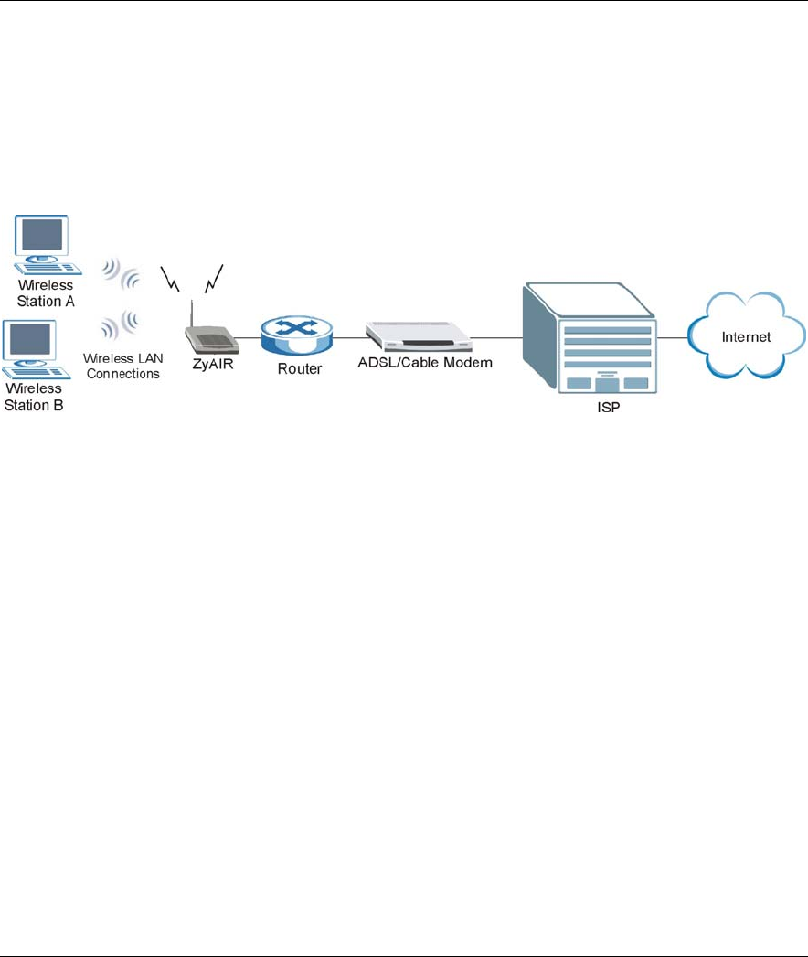
1.3.1 Internet Access Application
The ZyAIR is an ideal access solution for wireless Internet connection. A typical Internet access application
for your ZyAIR is shown as follows.
Figure 1-1 Internet Access Application
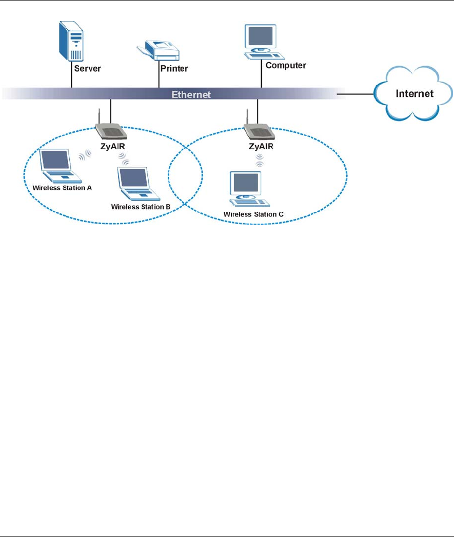
1.3.2 Corporation Network Application
In situations where users are always on the move in the coverage area but still need access to corporate
network access, the ZyAIR is an ideal solution for wireless stations to connect to the corporate network
without expensive network cabling.
The following figure depicts a typical application of the ZyAIR in an enterprise environment. The three
computers with wireless adapters are allowed to access the network resource through the ZyAIR after
account validation by the network authentication server.
ZyAIR B-500 Wireless Access Point User’s Guide
Getting to Know Your ZyAIR 1-5
Figure 1-2 Corporation Network Application
ZyAIR B-500 Wireless Access Point User’s Guide
Introducing the Web Configurator 2-1
Chapter 2
Introducing the Web Configurator
This chapter describes how to access the ZyAIR web configurator and provides an overview of its
screens. The default IP address of the ZyAIR is 192.168.1.2.
2.1 Accessing the ZyAIR Web Configurator
Step 1. Make sure your ZyAIR hardware is properly connected (refer to the Quick Installation Guide).
Step 2. Prepare your computer/computer network to connect to the ZyAIR (refer to the appendix).
Step 3. Launch your web browser.
Step 4. Type "192.168.1.2" (default) as the URL.
Step 5. Type "1234" (default) as the password and click Login. In some versions, the default password
appears automatically - if this is the case, click Login.
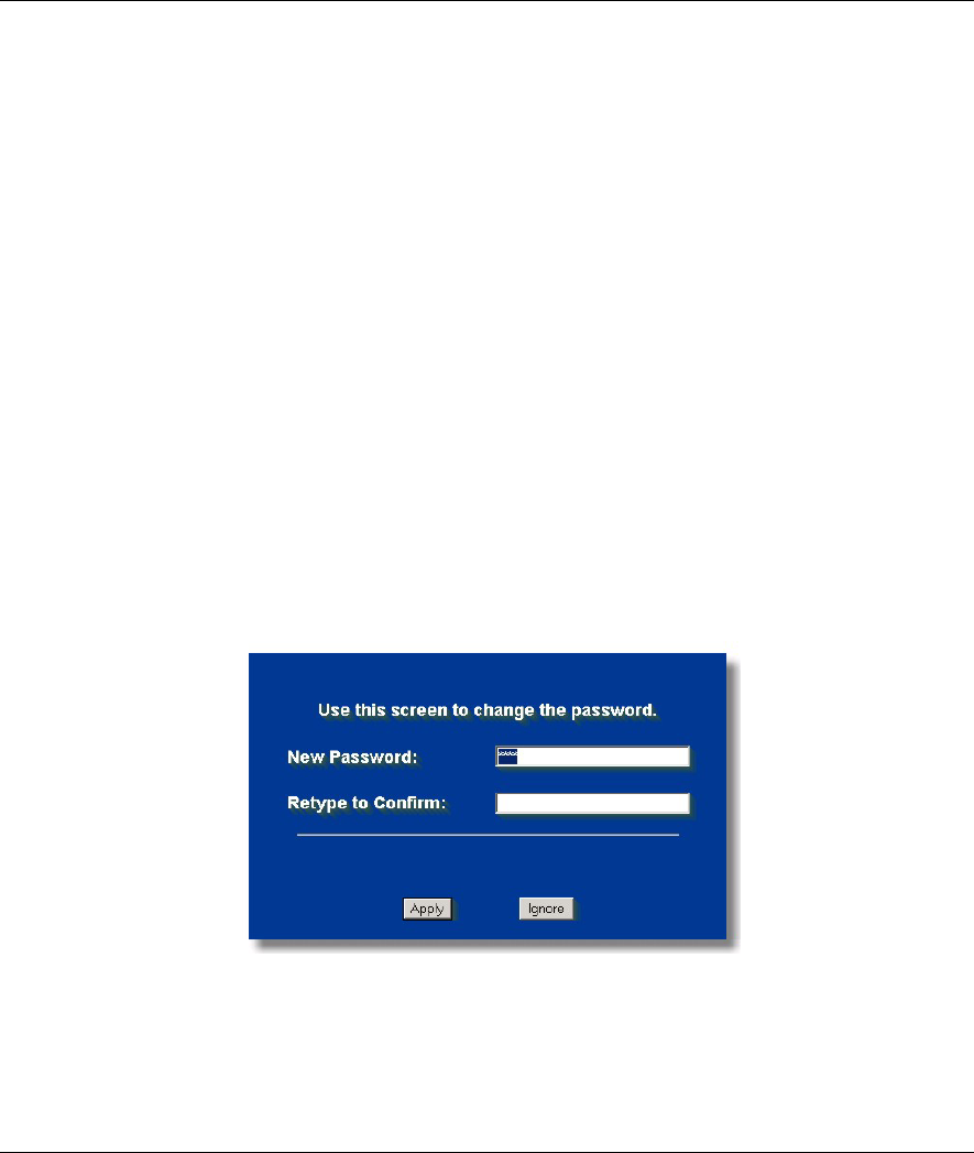
Step 6. You should see a screen asking you to change your password (highly recommended) as shown
next. Type a new password (and retype it to confirm) and click Apply or click Ignore to allow
access without password change.
Figure 2-1 Change Password Screen
Step 7. You should now see the SYSTEM screen.

ZyAIR B-500 Wireless Access Point User’s Guide
2-2 Introducing the Web Configurator
The management session automatically times out when the time period set in the
Administrator Inactivity Timer field expires (default five minutes). Simply log back into
the ZyAIR if this happens to you.
2.2 Resetting the ZyAIR
If you forget your password or cannot access the ZyAIR, you will need to reload the factory-default
configuration file or use the RESET button on the top panel of the ZyAIR. Uploading this configuration file
replaces the current configuration file with the factory-default configuration file. This means that you will
lose all configurations that you had previously. The password will be reset to “1234”, also.
2.2.1 Method of Restoring Factory-Defaults
You can erase the current configuration and restore factory defaults in three ways:
1. Use the RESET button on the top panel of the ZyAIR to upload the default configuration file (hold this
button in for about 10 seconds or until the Link LED turns red). Use this method for cases when the
password or IP address of the ZyAIR is not known.
2. Use the web configurator to restore defaults (refer to the chapter on maintenance).
3. Transfer the configuration file to your ZyAIR using FTP. See later in the part on SMT configuration for
more information.
ZyAIR B-500 Wireless Access Point User’s Guide
Introducing the Web Configurator 2-3
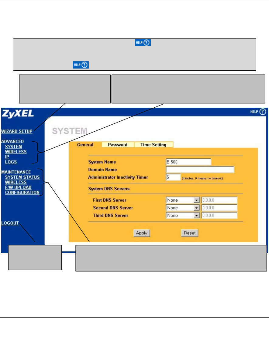
2.3 Navigating the ZyAIR Web Configurator
The following summarizes how to navigate the web configurator.
Follow the instructions below or click the icon (located in the top right corner
of most screens) to view online help.
The icon does not appear in the main screen.
Figure 2-2 Navigating the ZyAIR Web Configurator
Click the links under MAINTENANCE to view information about your ZyAIR or
upgrade configuration/firmware files. Maintenance includes SYSTEM STATUS
(Statistics), WIRELESS (Association List and Channel Usage), F/W (firmware)
U
PL
O
AD
,
CO
NFI
GU
RATI
O
N
(
B
ac
k
up,
R
esto
r
e
a
n
d
D
e
f
au
l
t
)
.
Click LOGOUT at
any time to exit the
web configurator.
Click the links under ADVANCED to configure advanced features
such as SYSTEM (General Setup, Password), WIRELESS
(Wireless, MAC Filter, Roaming, 802.1x, Local User Database and
RADIUS), IP and Logs (View reports and Log Settings).
Click WIZARD SETUP for initial
configuration including general setup,
Wireless LAN setup and IP address
assignment.

ZyAIR B-500 Wireless Access Point User’s Guide
Wizard Setup 3-1
Chapter 3
Wizard Setup
This chapter provides information on the Wizard Setup screens in the web configurator.
3.1 Wizard Setup Overview
The web configurator’s setup wizard helps you configure your ZyAIR for wireless stations to access your
wired LAN.
3.1.1 Channel
The range of radio frequencies used by IEEE 802.11b wireless devices is called a “channel”. Channels
available depend on your geographical area. You may have a choice of channels (for your region) so you
should use a different channel than an adjacent AP (access point) to reduce interference. Interference occurs
when radio signals from different access points overlap causing interference and degrading performance.
Adjacent channels partially overlap however. To avoid interference due to overlap, your AP should be on a
channel at least five channels away from a channel that an adjacent AP is using. For example, if your region
has 11 channels and an adjacent AP is using channel 1, then you need to select a channel between 6 or 11.
The ZyAIR’s “Scan” function is especially designed to automatically scan for a channel with the least
interference.
3.1.2 ESS ID
An Extended Service Set (ESS) is a group of access points connected to a wired LAN on the same subnet. An
ESS ID uniquely identifies each set. All access points and their associated wireless stations in the same set
must have the same ESSID.
3.1.3 WEP Encryption
WEP (Wired Equivalent Privacy) encrypts data frames before transmitting over the wireless network. WEP
encryption scrambles the data transmitted between the wireless stations and the access points to keep network
communications private. It encrypts unicast and multicast communications in a network. Both the wireless
stations and the access points must use the same WEP key for data encryption and decryption.
.
ZyAIR B-500 Wireless Access Point User’s Guide
3-2 Wizard Setup
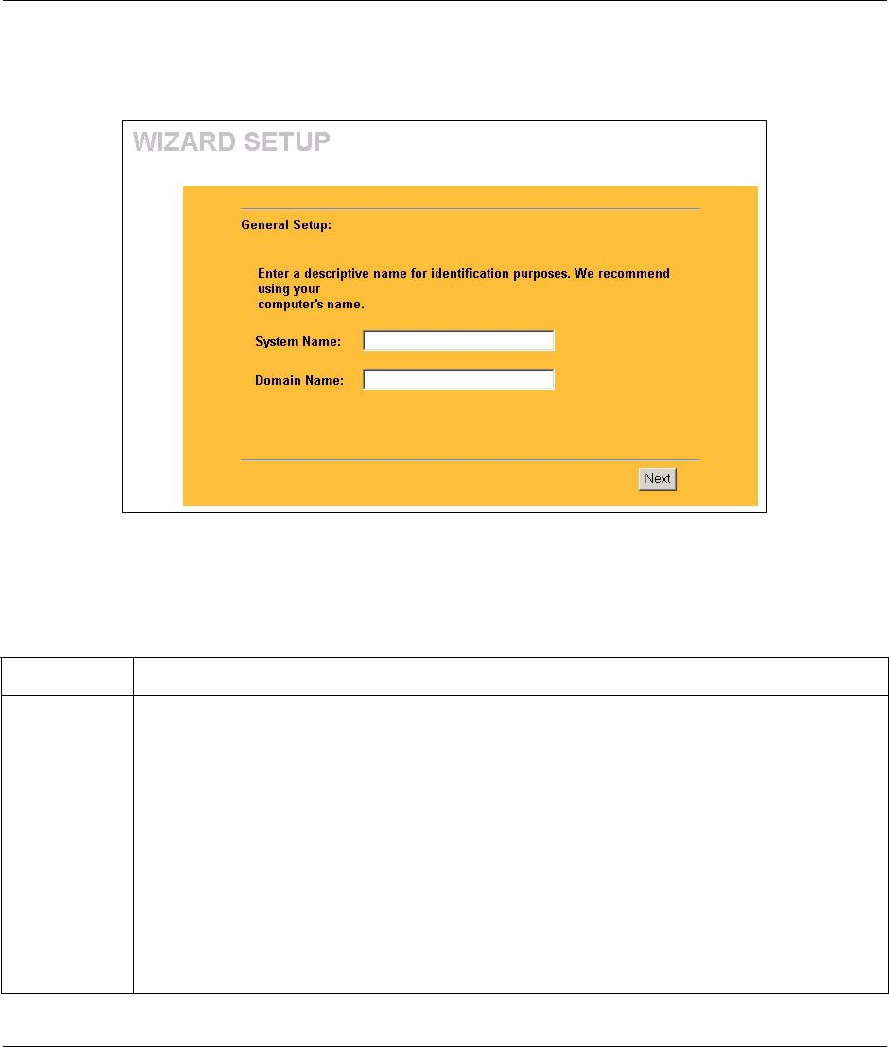
3.2 Wizard Setup: General Setup
General Setup contains administrative and system-related information.
Figure 3-1 Wizard 1 : General Setup
The following table describes the labels in this screen.
Table 3-1 Wizard 1 : General Setup
LABEL DESCRIPTION
System Name It is recommended you type your computer's "Computer name".
In Windows 95/98 click Start, Settings, Control Panel, Network. Click the Identification
tab, note the entry for the Computer Name field and enter it as the System Name.
In Windows 2000, click Start, Settings, Control Panel and then double-click System.
Click the Network Identification tab and then the Properties button. Note the entry for
the Computer name field and enter it as the System Name.
In Windows XP, click Start, My Computer, View system information and then click the
Computer Name tab. Note the entry in the Full computer name field and enter it as the
ZyAIR System Name.
This name can be up to 30 alphanumeric characters long. Spaces are not allowed, but
dashes "-" and underscores "_" are accepted.
ZyAIR B-500 Wireless Access Point User’s Guide
Wizard Setup 3-3
Table 3-1 Wizard 1 : General Setup
LABEL DESCRIPTION
Domain Name This is not a required field. Leave this field blank or enter the domain name here if you know
it.
Next Click Next to proceed to the next screen.
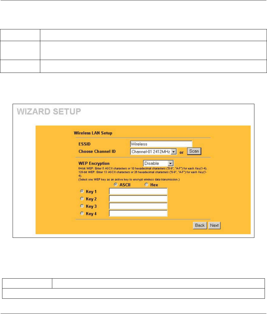
3.3 Wizard Setup: Wireless LAN
Use the second wizard screen to set up the wireless LAN.
Figure 3-2 Wizard 2 : Wireless LAN Setup
The following table describes the labels in this screen.
Table 3-2 Wizard 2 : Wireless LAN Setup
LABEL DESCRIPTION
Wireless LAN Setup

ZyAIR B-500 Wireless Access Point User’s Guide
3-4 Wizard Setup
Table 3-2 Wizard 2 : Wireless LAN Setup
LABEL DESCRIPTION
ESSID Enter a descriptive name (up to 32 printable 7-bit ASCII characters) for the wireless
LAN.
If you change this field on the ZyAIR, make sure all wireless stations use the same
ESSID in order to access the network.
Choose Channel
ID To manually set the ZyAIR to use a channel, select a channel from the drop-down list
box. Open the Channel Usage Table screen to make sure the channel is not already
used by another AP or independent peer-to-peer wireless network.
To have the ZyAIR automatically select a channel, click Scan instead.
Scan Click this button to have the ZyAIR automatically scan for and select a channel with
the least interference.
WEP Encryption Select Disable allows all wireless computers to communicate with the access points
without any data encryption.
Select 64-bit WEP or 128-bit WEP to allow data encryption.
ASCII Select this option in order to enter ASCII characters as the WEP keys.
Hex Select this option to enter hexadecimal characters as the WEP keys.
The preceding 0x is entered automatically.
Key 1 to Key 4 The WEP keys are used to encrypt data. Both the ZyAIR and the wireless stations
must use the same WEP key for data transmission.
If you chose 64-bit WEP, then enter any 5 ASCII characters or 10 hexadecimal
characters ("0-9", "A-F").
If you chose 128-bit WEP, then enter 13 ASCII characters or 26 hexadecimal
characters ("0-9", "A-F").
You must configure all four keys, but only one key can be activated at any one time.
The default key is key 1.
Next Click Next to continue.
Back Click Back to return to the previous screen.
3.4 Wizard Setup: IP Address
The third wizard screen allows you to configure IP address assignment.

ZyAIR B-500 Wireless Access Point User’s Guide
Wizard Setup 3-5
3.4.1 IP Address Assignment
Every computer on the Internet must have a unique IP address. If your networks are isolated from the
Internet, for instance, only between your two branch offices, you can assign any IP addresses to the hosts
without problems. However, the Internet Assigned Numbers Authority (IANA) has reserved the following
three blocks of IP addresses specifically for private networks.
Table 3-3 Private IP Address Ranges
10.0.0.0 - 10.255.255.255
172.16.0.0 - 172.31.255.255
192.168.0.0 - 192.168.255.255
You can obtain your IP address from the IANA, from an ISP or have it assigned by a private network. If you
belong to a small organization and your Internet access is through an ISP, the ISP can provide you with the
Internet addresses for your local networks. On the other hand, if you are part of a much larger organization,
you should consult your network administrator for the appropriate IP addresses.
Regardless of your particular situation, do not create an arbitrary IP address;
always follow the guidelines above. For more information on address assignment,
please refer to RFC 1597, Address Allocation for Private Internets and RFC 1466,
Guidelines for Management of IP Address Space.
3.4.2 IP Address and Subnet Mask
Similar to the way houses on a street share a common street name, so too do computers on a LAN share one
common network number.
Where you obtain your network number depends on your particular situation. If the ISP or your network
administrator assigns you a block of registered IP addresses, follow their instructions in selecting the IP
addresses and the subnet mask.
If the ISP did not explicitly give you an IP network number, then most likely you have a single user account
and the ISP will assign you a dynamic IP address when the connection is established. The Internet Assigned
Number Authority (IANA) reserved this block of addresses specifically for private use; please do not use any
other number unless you are told otherwise. Let's say you select 192.168.1.0 as the network number; which
covers 254 individual addresses, from 192.168.1.1 to 192.168.1.254 (zero and 255 are reserved). In other
words, the first three numbers specify the network number while the last number identifies an individual
computer on that network.
Once you have decided on the network number, pick an IP address that is easy to remember, for instance,
192.168.1.2, for your ZyAIR, but make sure that no other device on your network is using that IP address.
ZyAIR B-500 Wireless Access Point User’s Guide
3-6 Wizard Setup
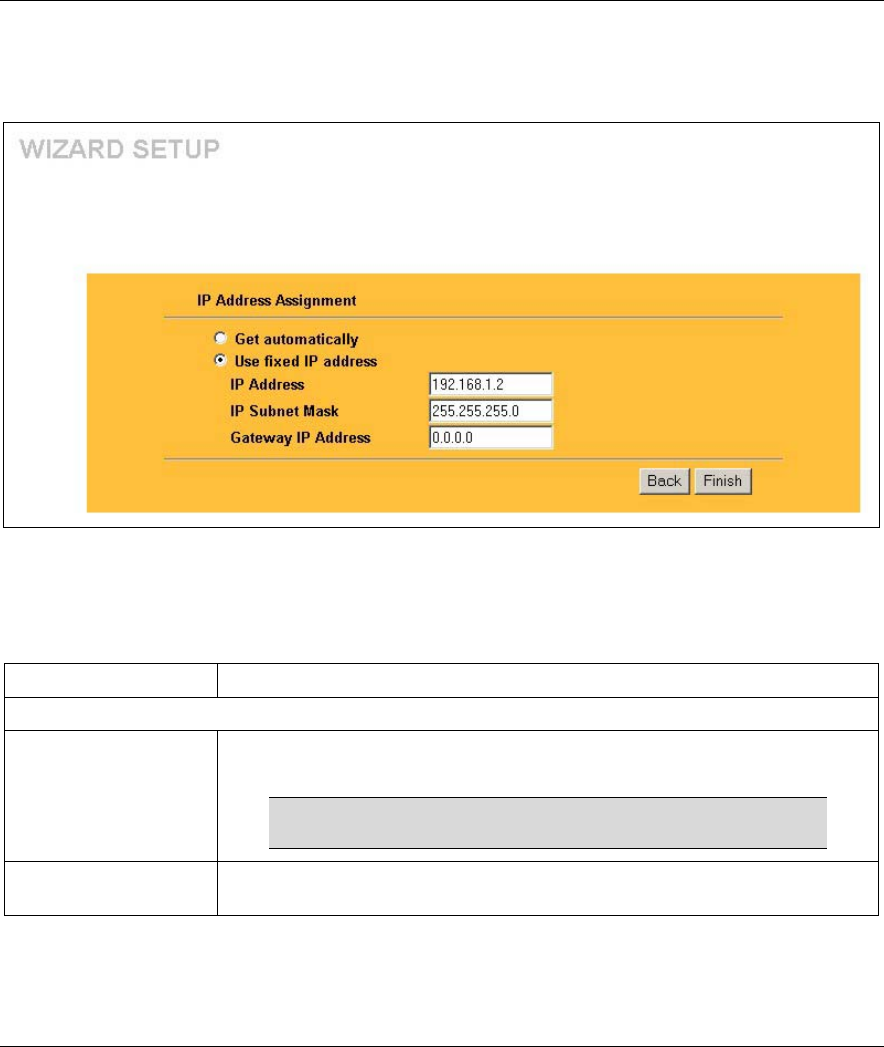
The subnet mask specifies the network number portion of an IP address. Your ZyAIR will compute the
subnet mask automatically based on the IP address that you entered. You don't need to change the subnet
mask computed by the ZyAIR unless you are instructed to do otherwise.
Figure 3-3 Wizard 3 : IP Address Assignment
The following table describes the labels in this screen.
Table 3-4 Wizard 3 : IP Address Assignment
LABEL DESCRIPTION
IP Address Assignment
Get automatically Select this option if your ZyAIR is using a dynamically assigned IP address from
a DHCP server each time.
You must know the IP address assigned to the ZyAIR (by
the DHCP server) to access the ZyAIR again.
Use fixed IP address Select this option if your ZyAIR is using a static IP address. When you select
this option, fill in the fields below.
ZyAIR B-500 Wireless Access Point User’s Guide
Wizard Setup 3-7
Table 3-4 Wizard 3 : IP Address Assignment
LABEL DESCRIPTION
IP Address Enter the IP address of your ZyAIR in dotted decimal notation.
If you change the ZyAIR's IP address, you must use the
new IP address if you want to access the web
configurator again.
IP Subnet Mask Enter the subnet mask.
Gateway IP Address Enter the IP address of a gateway. The gateway is an immediate neighbor of
your ZyAIR that will forward the packet to the destination. On the LAN, the
gateway must be a router on the same segment as your ZyAIR; over the WAN,
the gateway must be the IP address of one of the remote node.
Back Click Back to return to the previous screen.
Finish Click Finish to proceed to complete the Wizard setup.
3.5 Basic Setup Complete
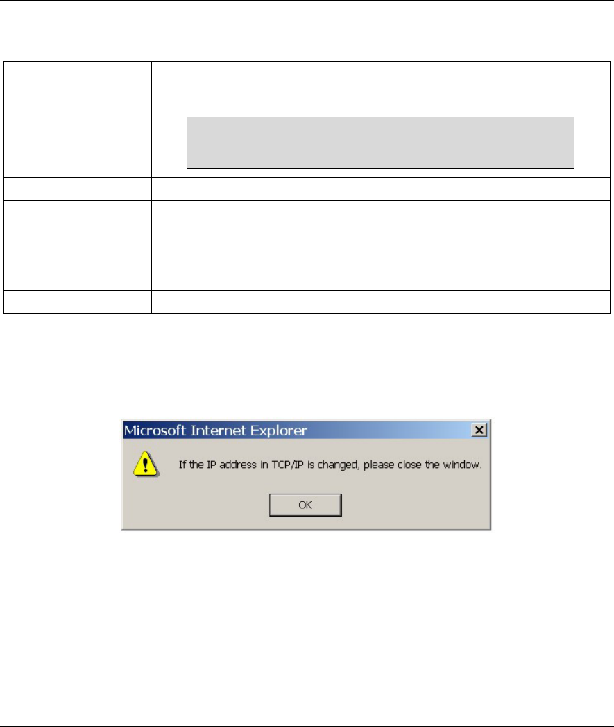
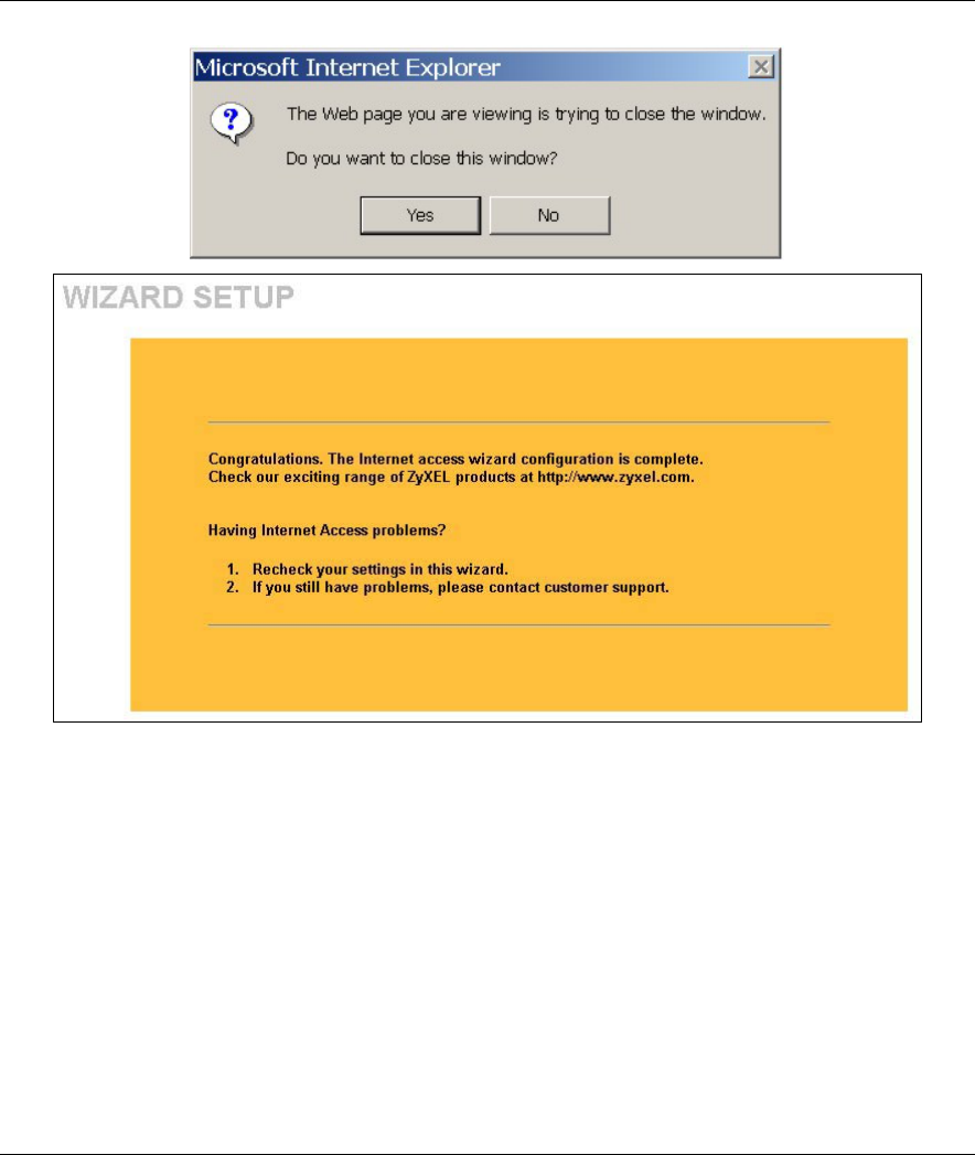
When you click Finish in the Wizard 3 IP Address Assignment screen, a warning window display as
shown. Click OK to close the window and log in to the web configurator again using the new IP address if
you change the default IP address (192.168.1.2).
You have successfully set up the ZyAIR. A screen displays prompting you to close the web browser.
Click Yes. Otherwise, click No and the congratulations screen shows next.
ZyAIR B-500 Wireless Access Point User’s Guide
3-8 Wizard Setup
Well done! You have successfully set up your ZyAIR to operate on your network and access the Internet.

System, Wireless and IP
II
Part II:
SYSTEM, WIRELESS AND IP
This part covers the information and web configurator screens of System, Wireless and IP.
ZyAIR B-500 Wireless Access Point User’s Guide
System Screens 4-1
Chapter 4
System Screens
This chapter provides information on the System screens.
4.1 System Overview
This section provides information on general system setup.
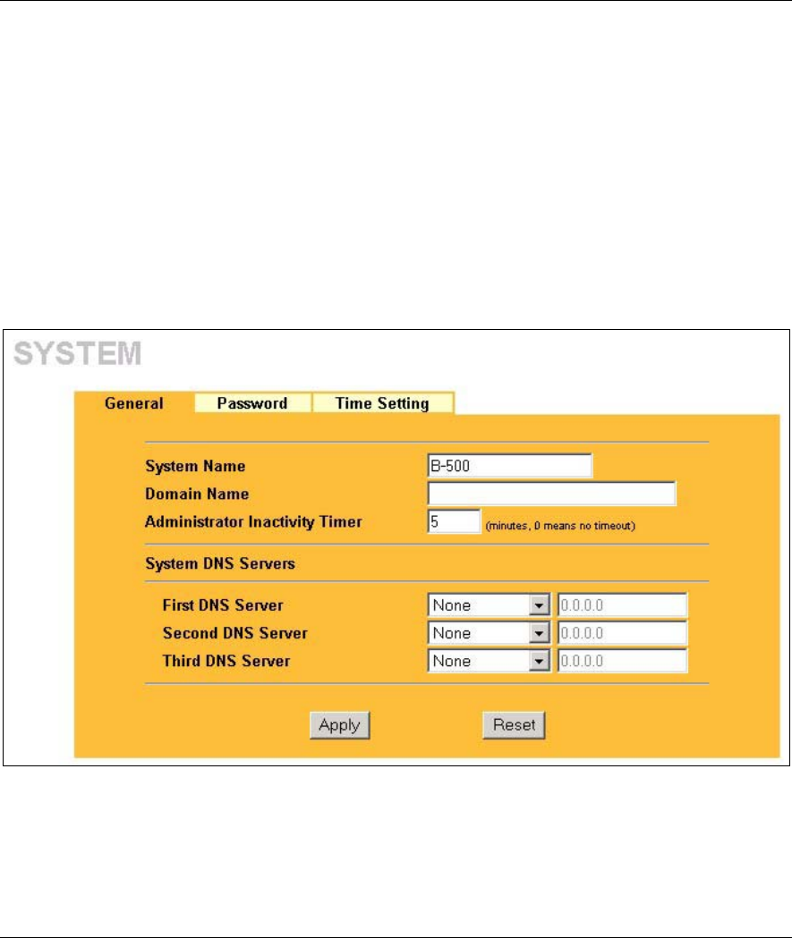
4.2 Configuring General Setup
Click SYSTEM to open the General screen.
Figure 4-1 System General Setup
The following table describes the labels in this screen.

ZyAIR B-500 Wireless Access Point User’s Guide
4-2 System Screens
Table 4-1 System General Setup
LABEL DESCRIPTION
System Name Type a descriptive name to identify the ZyAIR in the Ethernet network.
This name can be up to 30 alphanumeric characters long. Spaces are not allowed, but
dashes "-" and underscores "_" are accepted.
Domain Name This is not a required field. Leave this field blank or enter the domain name here if you
know it.
Administrator
Inactivity Timer
Type how many minutes a management session (either via the web configurator or
SMT) can be left idle before the session times out.
The default is 5 minutes. After it times out you have to log in with your password again.
Very long idle timeouts may have security risks.
A value of "0" means a management session never times out, no matter how long it
has been left idle (not recommended).
System DNS Servers
First DNS Server
Second DNS
Server
Third DNS
Server
Select From DHCP if your DHCP server dynamically assigns DNS server information
(and the ZyAIR's Ethernet IP address). The field to the right displays the (read-only)
DNS server IP address that the DHCP assigns.
Select User-Defined if you have the IP address of a DNS server. Enter the DNS
server's IP address in the field to the right. If you chose User-Defined, but leave the IP
address set to 0.0.0.0, User-Defined changes to None after you click Apply. If you set
a second choice to User-Defined, and enter the same IP address, the second User-
Defined changes to None after you click Apply.
Select None if you do not want to configure DNS servers. If you do not configure a
DNS server, you must know the IP address of a machine in order to access it.
The default setting is None.
Apply Click Apply to save your changes back to the ZyAIR.
Reset Click Reset to reload the previous configuration for this screen.
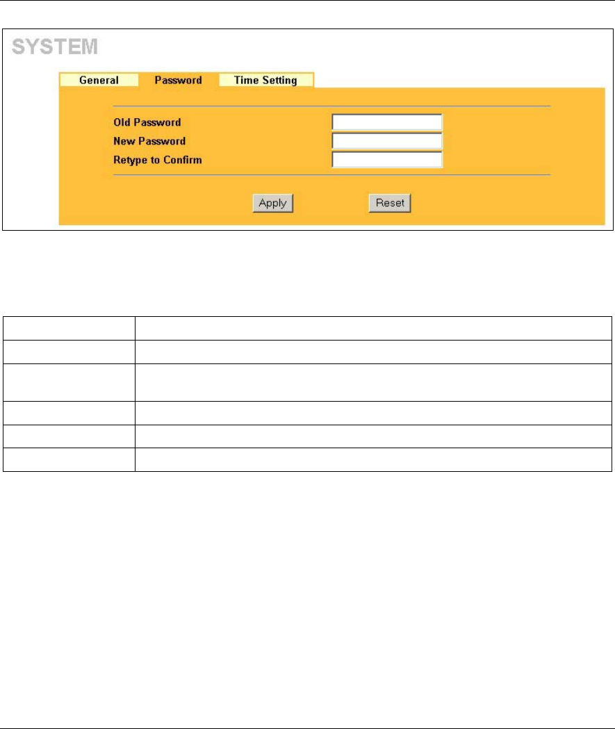
4.3 Configuring Password
To change your ZyAIR’s password (recommended), click SYSTEM and then the Password tab. The screen
appears as shown. This screen allows you to change the ZyAIR’s password.
If you forget your password (or the ZyAIR IP address), you will need to reset the ZyAIR. See the section on
resetting the ZyAIR for details.
ZyAIR B-500 Wireless Access Point User’s Guide
System Screens 4-3
Figure 4-2 Password
The following table describes the labels in this screen.
Table 4-2 Password
LABEL DESCRIPTION
Old Password Type in your existing system password (1234 is the default password).
New Password Type your new system password (up to 31 characters). Note that as you type a
password, the screen displays an asterisk (*) for each character you type.
Retype to Confirm Retype your new system password for confirmation.
Apply Click Apply to save your changes back to the ZyAIR.
Reset Click Reset to reload the previous configuration for this screen.
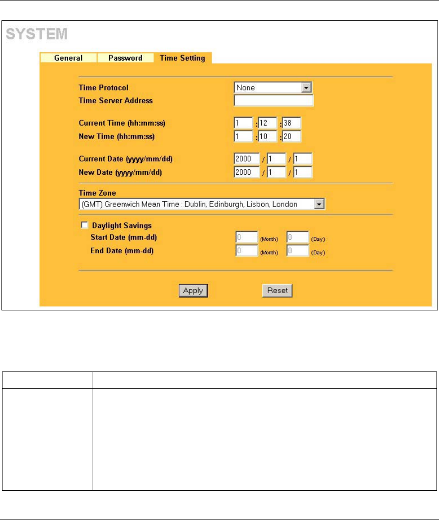
4.4 Configuring Time Setting
To change your ZyAIR’s time and date, click SYSTEM and then the Time Setting tab. The screen appears
as shown. Use this screen to configure the ZyAIR’s time based on your local time zone.
ZyAIR B-500 Wireless Access Point User’s Guide
4-4 System Screens
Figure 4-3 Time Setting
The following table describes the labels in this screen.
Table 4-3 Time Setting
LABEL DESCRIPTION
Time Protocol Select the time service protocol that your time server sends when you turn on the
ZyAIR. Not all time servers support all protocols, so you may have to check with
your ISP/network administrator or use trial and error to find a protocol that works.
The main difference between them is the format.
Daytime (RFC 867) format is day/month/year/time zone of the server.
Time (RFC 868) format displays a 4-byte integer giving the total number of seconds
since 1970/1/1 at 0:0:0.
The default, NTP (RFC 1305), is similar to Time (RFC 868).
Select None to enter the time and date manually.

ZyAIR B-500 Wireless Access Point User’s Guide
System Screens 4-5
Table 4-3 Time Setting
LABEL DESCRIPTION
Time Server
Address
Enter the IP address or the URL of your time server. Check with your ISP/network
administrator if you are unsure of this information.
Current Time
(hh:mm:ss)
This field displays the time of your ZyAIR.
Each time you reload this page, the ZyAIR synchronizes the time with the time
server.
New Time
(hh:mm:ss)
This field displays the last updated time from the time server.
When you select None in the Time Protocol field, enter the new time in this field
and then click Apply.
Current Date
(yyyy/mm/dd)
This field displays the date of your ZyAIR.
Each time you reload this page, the ZyAIR synchronizes the time with the time
server.
New Date
(yyyy/mm/dd)
This field displays the last updated date from the time server.
When you select None in the Time Protocol field, enter the new date in this field
and then click Apply.
Time Zone Choose the time zone of your location. This will set the time difference between your
time zone and Greenwich Mean Time (GMT).
Daylight Savings Select this option if you use daylight savings time. Daylight saving is a period from
late spring to early fall when many countries set their clocks ahead of normal local
time by one hour to give more daytime light in the evening.
Start Date (mm-dd) Enter the month and day that your daylight-savings time starts on if you selected
Daylight Savings.
End Date (mm-dd) Enter the month and day that your daylight-savings time ends on if you selected
Daylight Savings.
Apply Click Apply to save your changes back to the ZyAIR.
Reset Click Reset to reload the previous configuration for this screen.
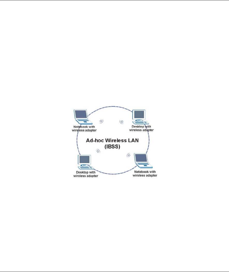
ZyAIR B-500 Wireless Access Point User’s Guide
System Screens 5-1
Chapter 5
Wireless Configuration and Roaming
This chapter discusses how to configure Wireless and Roaming screens on the ZyAIR.
5.1 Wireless LAN Overview
This section introduces the wireless LAN (WLAN) and some basic scenarios.
5.1.1 IBSS
An Independent Basic Service Set (IBSS), also called an Ad-hoc network, is the simplest WLAN
configuration. An IBSS is defined as two or more computers with wireless adapters within range of each
other that from an independent (wireless) network without the need of an access point (AP).
Figure 5-1 IBSS (Ad-hoc) Wireless LAN
5.1.2 BSS
A Basic Service Set (BSS) exists when all communications between wireless stations or between a wireless
station and a wired network client go through one access point (AP).
Intra-BSS traffic is traffic between wireless stations in the BSS. When Intra-BSS is enabled, wireless station
A and B can access the wired network and communicate with each other. When Intra-BSS is disabled,
wireless station A and B can still access the wired network but cannot communicate with each other.
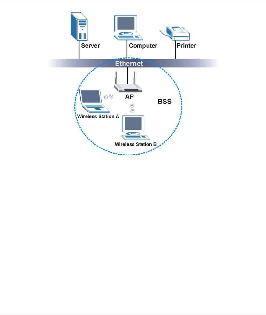
ZyAIR B-500 Wireless Access Point User’s Guide
5-2 Wireless Configuration and Roaming
Figure 5-2 Basic Service set
5.1.3 ESS
An Extended Service Set (ESS) consists of a series of overlapping BSSs, each containing an access point,
with each access point connected together by a wired network. This wired connection between APs is called
a Distribution System (DS). An ESSID (ESS IDentification) uniquely identifies each ESS. All access points
and their associated wireless stations within the same ESS must have the same ESSID in order to
communicate.
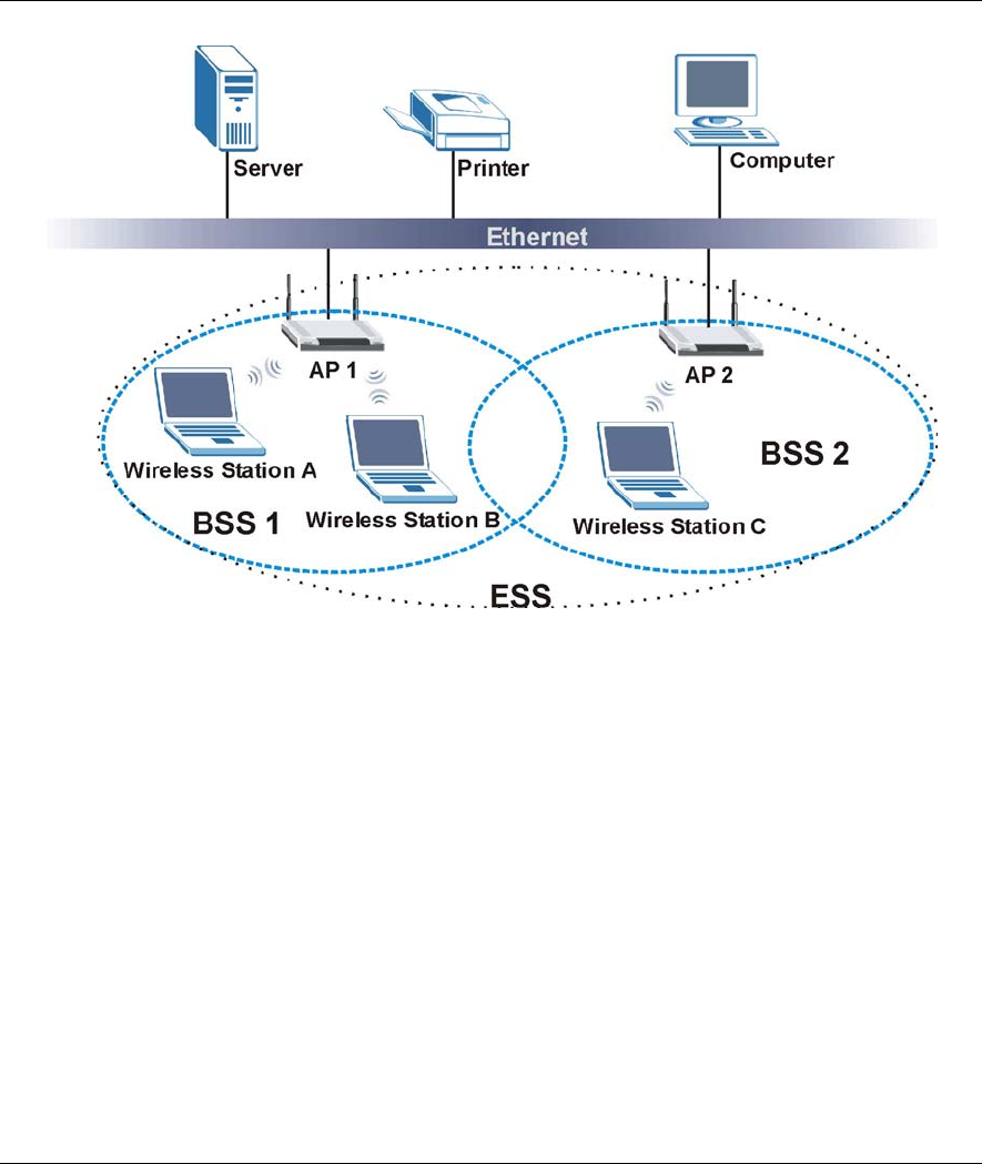
ZyAIR B-500 Wireless Access Point User’s Guide
System Screens 5-3
Figure 5-3 Extended Service Set
5.2 Wireless LAN Basics
Refer also to the chapter on wizard setup for more background information on Wireless LAN features, such
as channels.
5.2.1 RTS/CTS
A hidden node occurs when two stations are within range of the same access point, but are not within range
of each other. The following figure illustrates a hidden node. Both stations (STA) are within range of the
access point (AP) or wireless gateway, but out-of-range of each other, so they cannot “hear” each other, that
is they do not know if the channel is currently being used. Therefore, they are considered hidden from each
other.
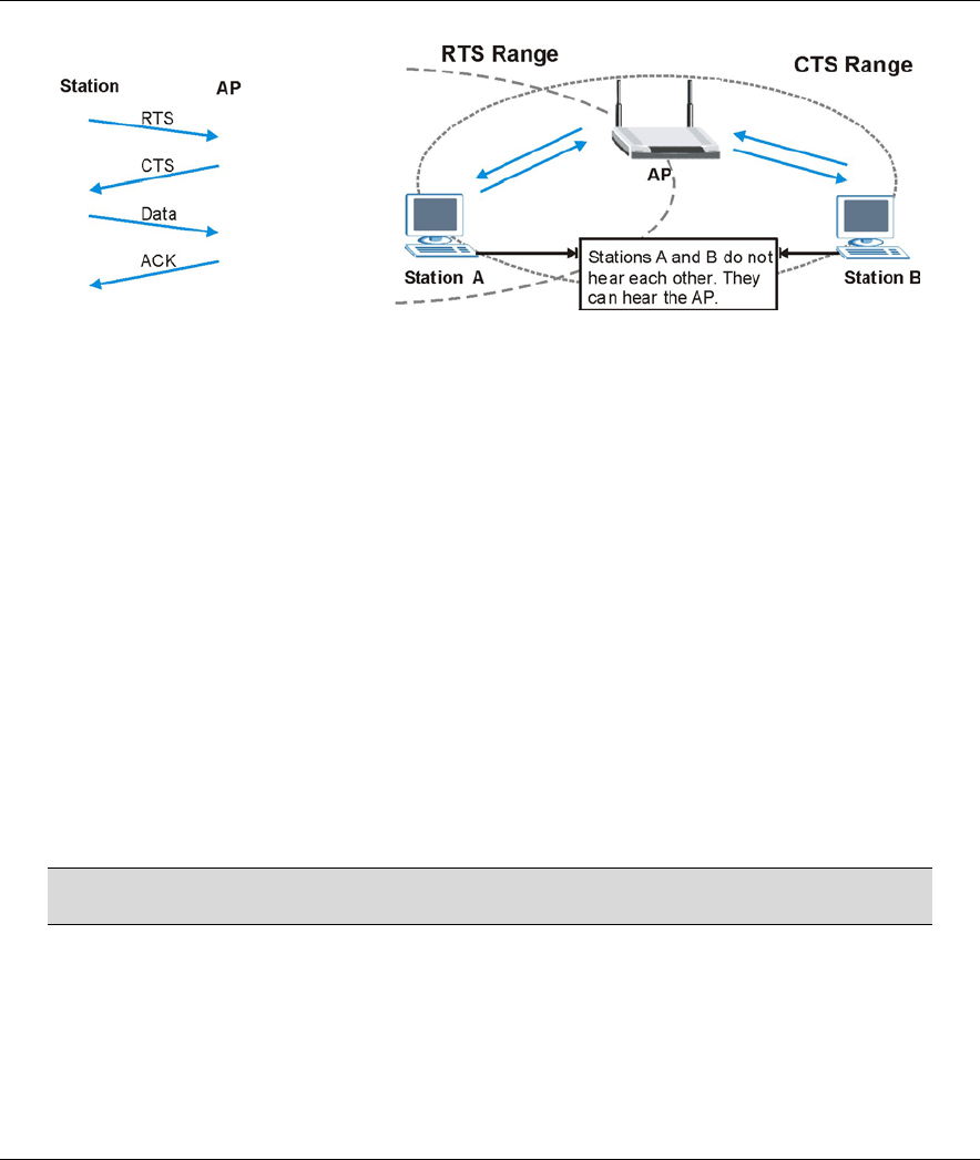
ZyAIR B-500 Wireless Access Point User’s Guide
5-4 Wireless Configuration and Roaming
Figure 5-4 RTS/CTS
When station A sends data to the AP, it might not know that the station B is already using the channel. If
these two stations send data at the same time, collisions may occur when both sets of data arrive at the AP at
the same time, resulting in a loss of messages for both stations.
RTS/CTS is designed to prevent collisions due to hidden nodes. An RTS/CTS defines the biggest size data
frame you can send before an RTS (Request To Send)/CTS (Clear to Send) handshake is invoked.
When a data frame exceeds the RTS/CTS value you set (between 0 to 2432 bytes), the station that wants to
transmit this frame must first send an RTS (Request To Send) message to the AP for permission to send it.
The AP then responds with a CTS (Clear to Send) message to all other stations within its range to notify
them to defer their transmission. It also reserves and confirms with the requesting station the time frame for
the requested transmission.
Stations can send frames smaller than the specified RTS/CTS directly to the AP without the RTS (Request
To Send)/CTS (Clear to Send) handshake.
You should only configure RTS/CTS if the possibility of hidden nodes exists on your network and the “cost”
of resending large frames is more than the extra network overhead involved in the RTS (Request To
Send)/CTS (Clear to Send) handshake.
If the RTS/CTS value is greater than the Fragmentation Threshold value (see next), then the RTS (Request
To Send)/CTS (Clear to Send) handshake will never occur as data frames will be fragmented before they
reach RTS/CTS size.
Enabling the RTS Threshold causes redundant network overhead that could
negatively affect the throughput performance instead of providing a remedy.
5.2.2 Fragmentation Threshold
A Fragmentation Threshold is the maximum data fragment size (between 256 and 2432 bytes) that can be
sent in the wireless network before the ZyAIR will fragment the packet into smaller data frames.
A large Fragmentation Threshold is recommended for networks not prone to interference while you should
set a smaller threshold for busy networks or networks that are prone to interference.
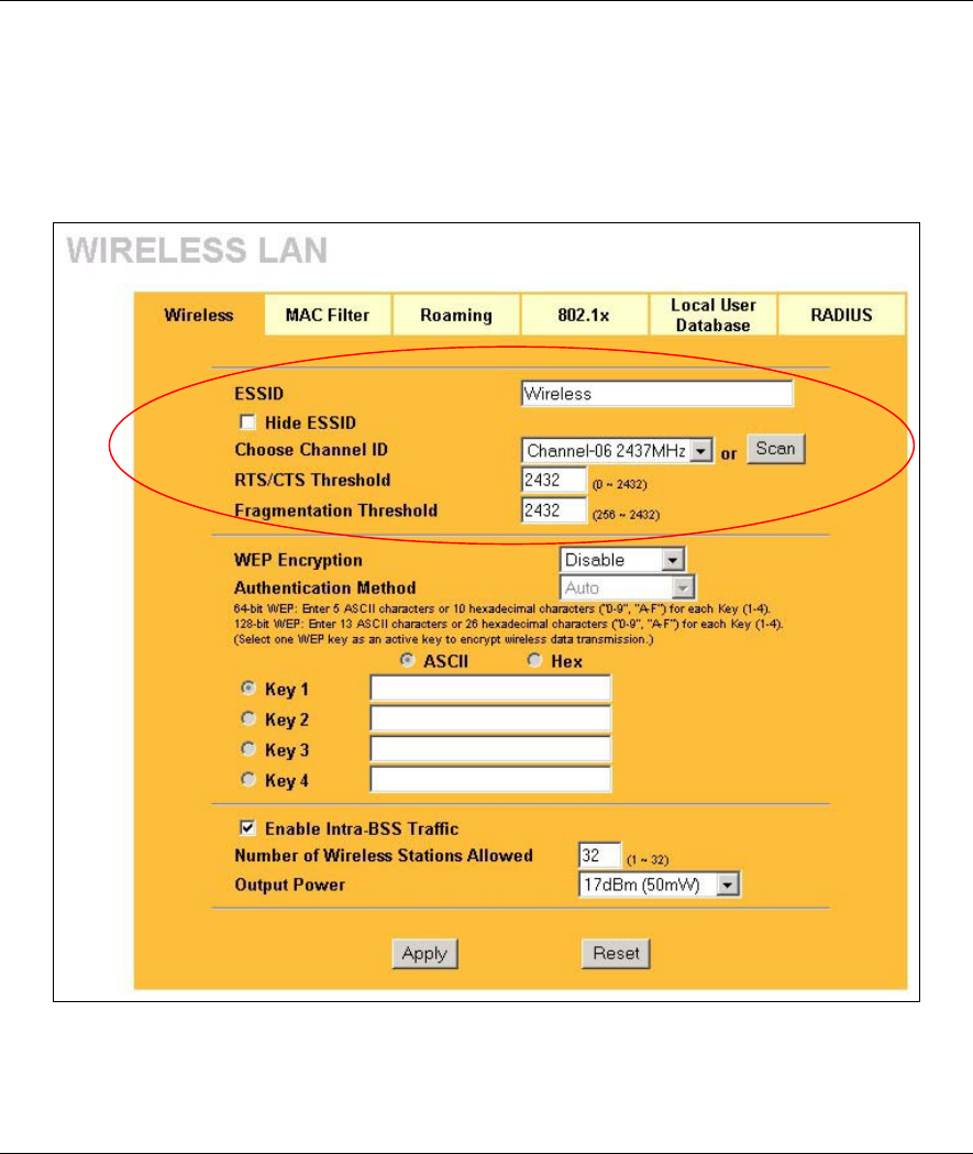
ZyAIR B-500 Wireless Access Point User’s Guide
System Screens 5-5
If the Fragmentation Threshold value is smaller than the RTS/CTS value (see previously) you set then the
RTS (Request To Send)/CTS (Clear to Send) handshake will never occur as data frames will be fragmented
before they reach RTS/CTS size.
5.3 Configuring Wireless
Click the WIRELESS link under ADVANCED to display the Wireless screen.
Figure 5-5 Wireless
The following table describes the general wireless LAN labels in this screen.

ZyAIR B-500 Wireless Access Point User’s Guide
5-6 Wireless Configuration and Roaming
Table 5-1 Wireless
LABEL DESCRIPTION
ESSID (Extended Service Set IDentity) The ESSID identifies the Service Set with which a
wireless station is associated. Wireless stations associating to the access point (AP)
must have the same ESSID. Enter a descriptive name (up to 32 printable 7-bit ASCII
characters) for the wireless LAN.
If you are configuring the ZyAIR from a computer connected to
the wireless LAN and you change the ZyAIR’s ESSID or WEP
settings, you will lose your wireless connection when you
press Apply to confirm. You must then change the wireless
settings of your computer to match the ZyAIR’s new settings.
Hide ESSID Select this check box to hide the ESSID in the outgoing beacon frame so a station
cannot obtain the ESSID through passive scanning using a site survey tool.
Choose
Channel ID
Set the operating frequency/channel depending on your particular region.
To manually set the ZyAIR to use a channel, select a channel from the drop-down list
box. Click WIRELESS under MAINTENANCE and then the Channel Usage tab to
open the Channel Usage screen to make sure the channel is not already used by
another AP or independent peer-to-peer wireless network.
To have the ZyAIR automatically select a channel, click Scan instead.
Refer to the chapter on wizard setup for more information about channels.
Scan Click this button to have the ZyAIR automatically scan for and select a channel with the
least interference.
RTS/CTS
Threshold
Enter a value between 0 and 2432. The default is 2432.
Fragmentation
Threshold
Enter a value between 256 and 2432. The default is 2432. It is the maximum data
fragment size that can be sent.
Apply Click Apply to save your changes back to the ZyAIR.
Reset Click Reset to begin configuring this screen afresh.
See the chapter on wireless security for information on the other labels in this screen.
5.4 Configuring Roaming
A wireless station is a device with an IEEE 802.11b compliant wireless adapters. An access point (AP) acts
as a bridge between the wireless and wired networks. An AP creates its own wireless coverage area. A
wireless station can associate with a particular access point only if it is within the access point’s coverage
area.
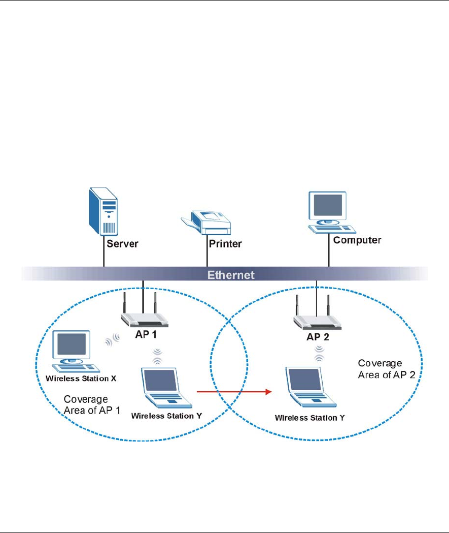
ZyAIR B-500 Wireless Access Point User’s Guide
System Screens 5-7
In a network environment with multiple access points, wireless stations are able to switch from one access
point to another as they move between the coverage areas. This is roaming. As the wireless station moves
from place to place, it is responsible for choosing the most appropriate access point depending on the signal
strength, network utilization or other factors.
The roaming feature on the access points allows the access points to relay information about the wireless
stations to each other. When a wireless station moves from a coverage area to another, it scans and uses the
channel of a new access point, which then informs the access points on the LAN about the change. The new
information is then propagated to the other access points on the LAN. An example is shown in Figure 5-6.
With roaming, a wireless LAN mobile user enjoys a continuous connection to the wired network through an
access point while moving around the wireless LAN.
If the roaming feature is not enabled on the access points, information is not communicated between the
access points when a wireless station moves between coverage areas. The wireless station may not be able to
communicate with other wireless stations on the network and vice versa.
Figure 5-6 Roaming Example
The steps below describe the roaming process.
Step 1. As wireless station Y moves from the coverage area of access point AP 1 to that of access point
AP 2, it scans and uses the signal of access point AP 2.
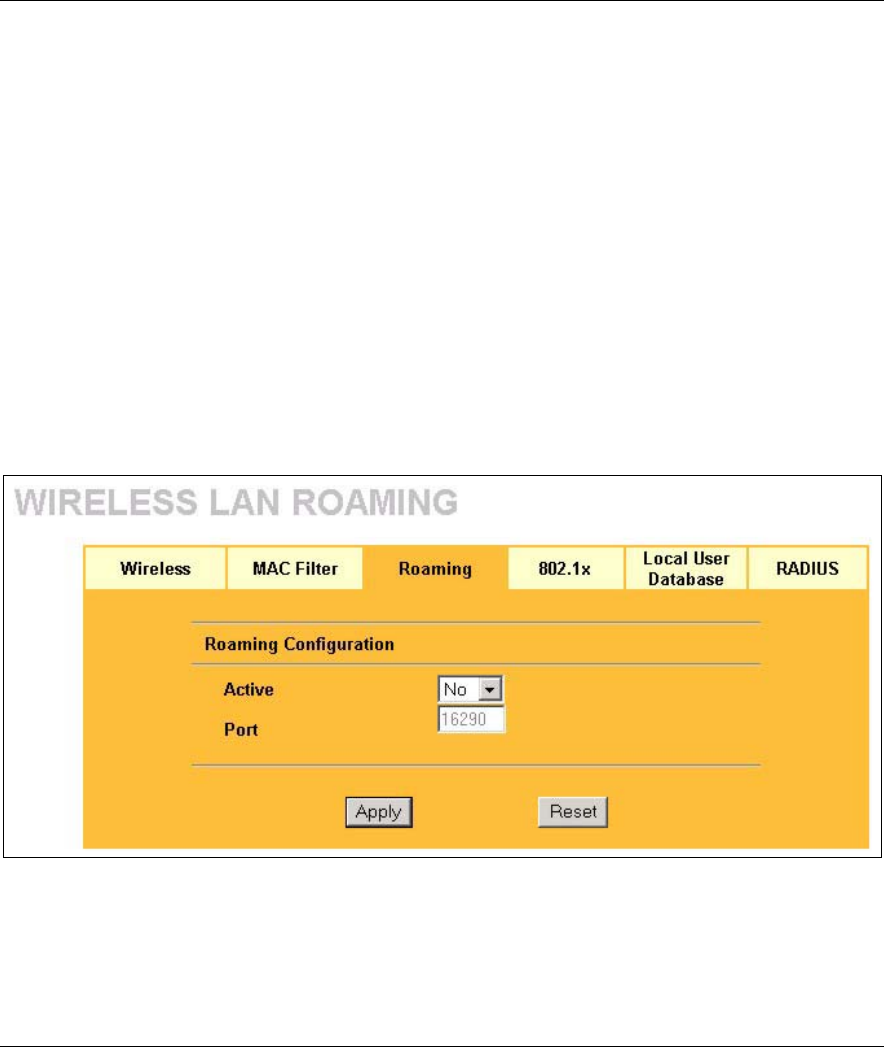
ZyAIR B-500 Wireless Access Point User’s Guide
5-8 Wireless Configuration and Roaming
Step 2. Access point AP 2 acknowledges the presence of wireless station Y and relays this information
to access point AP 1 through the wired LAN.
Step 3. Access point AP 1 updates the new position of wireless station.
Step 4. Wireless station Y sends a request to access point AP 2 for reauthentication.
5.4.1 Requirements for Roaming
The following requirements must be met in order for wireless stations to roam between the coverage areas.
1. All the access points must be on the same subnet and configured with the same ESSID.
2. If IEEE 802.1x user authentication is enabled and to be done locally on the access point, the new
access point must have the user profile for the wireless station.
3. The adjacent access points should use different radio channels when their coverage areas overlap.
4. All access points must use the same port number to relay roaming information.
5. The access points must be connected to the Ethernet and be able to get IP addresses from a DHCP
server if using dynamic IP address assignment.
To enable roaming on your ZyAIR, click the WIRELESS link under ADVANCED and then the Roaming
tab. The screen appears as shown.
Figure 5-7 Roaming
The following table describes the labels in this screen.

ZyAIR B-500 Wireless Access Point User’s Guide
System Screens 5-9
Table 5-2 Roaming
LABEL DESCRIPTION
Active Select Yes from the drop-down list box to enable roaming on the ZyAIR if you have two or
more ZyAIRs on the same subnet.
All APs on the same subnet and the wireless stations must have the
same ESSID to allow roaming.
Port # Enter the port number to communicate roaming information between access points. The
port number must be the same on all access points. The default is 16290. Make sure this
port is not used by other services.
Apply Click Apply to save your changes back to the ZyAIR.
Reset Click Reset to begin configuring this screen afresh.
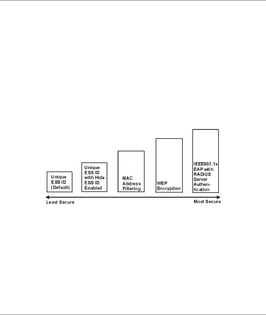
ZyAIR B-500 Wireless Access Point User’s Guide
Wireless Security 6-1
Chapter 6
Wireless Security
This chapter describes how to use the MAC Filter, 802.1x, Local User Database and RADIUS to
configure wireless security on your ZyAIR.
6.1 Wireless Security Overview
Wireless security is vital to your network to protect wireless communication between wireless stations,
access points and the wired network.
The figure below shows the possible wireless security levels on your ZyAIR. The highest security level relies
on EAP (Extensible Authentication Protocol) for authentication and utilizes dynamic WEP key exchange. It
requires interaction with a RADIUS (Remote Authentication Dial-In User Service) server either on the WAN
or your LAN to provide authentication service for wireless stations.
Figure 6-1 ZyAIR Wireless Security Levels
If you do not enable any wireless security on your ZyAIR, your network is accessible to any wireless
networking device that is within range.
6.2 WEP Overview
WEP (Wired Equivalent Privacy) as specified in the IEEE 802.11 standard provides methods for both data
encryption and wireless station authentication.
6.2.1 Data Encryption
WEP provides a mechanism for encrypting data using encryption keys. Both the AP and the wireless stations
must use the same WEP key to encrypt and decrypt data. Your ZyAIR allows you to configure up to four 64-
bit or 128-bit WEP keys, but only one key can be enabled at any one time.
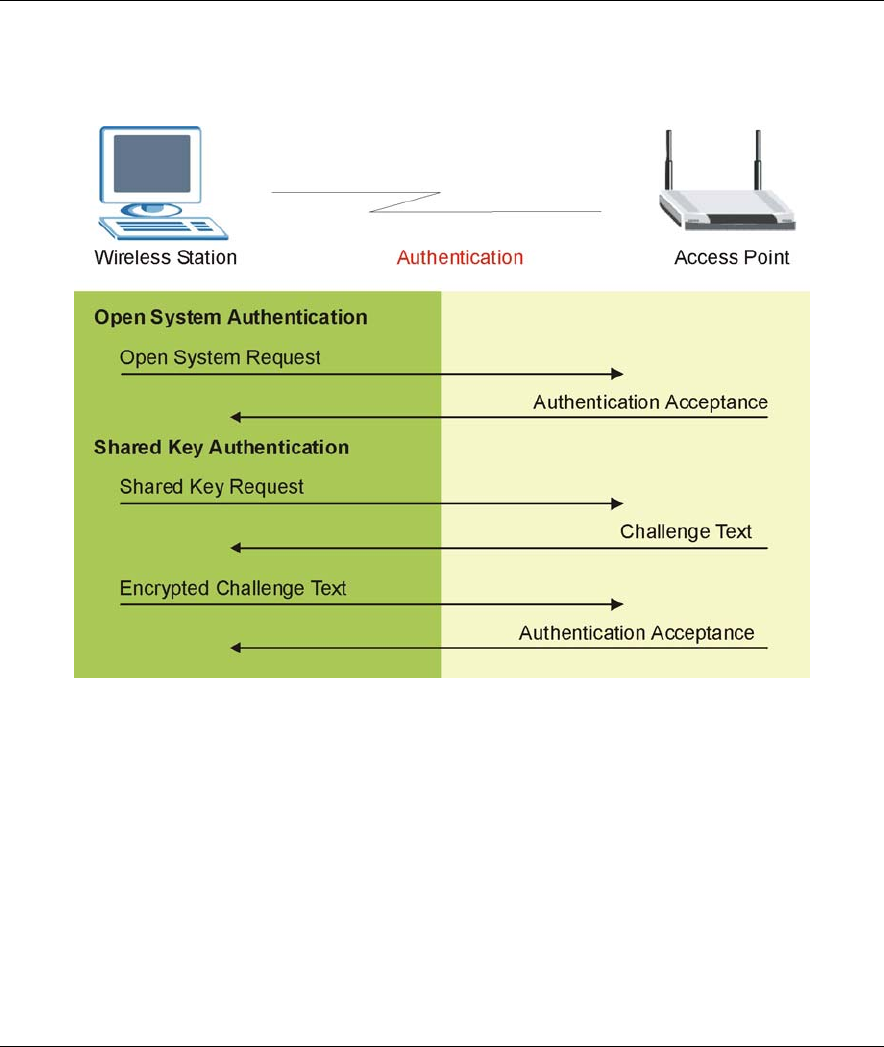
ZyAIR B-500 Wireless Access Point User’s Guide
6-2 Wireless Security
6.2.2 Authentication
Three different methods can be used to authenticate wireless stations to the network: Open System, Shared
Key, and Auto. The following figure illustrates the steps involved.
Figure 6-2 WEP Authentication Steps
Open system authentication involves an unencrypted two-message procedure. A wireless station sends an
open system authentication request to the AP, which will then automatically accept and connect the wireless
station to the network. In effect, open system is not authentication at all as any station can gain access to the
network.
Shared key authentication involves a four-message procedure. A wireless station sends a shared key
authentication request to the AP, which will then reply with a challenge text message. The wireless station
must then use the AP’s default WEP key to encrypt the challenge text and return it to the AP, which attempts
to decrypt the message using the AP’s default WEP key. If the decrypted message matches the challenge text,
the wireless station is authenticated.
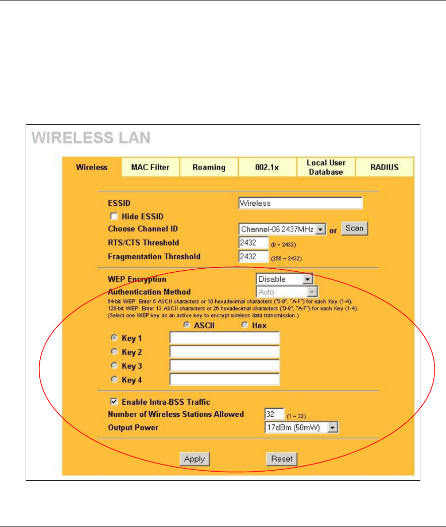
ZyAIR B-500 Wireless Access Point User’s Guide
Wireless Security 6-3
When your ZyAIR's authentication method is set to open system, it will only accept open system
authentication requests. The same is true for shared key authentication. However, when it is set to auto
authentication, the ZyAIR will accept either type of authentication request and the ZyAIR will fall back to
use open authentication if the shared key does not match.
6.3 Configuring WEP Encryption
In order to configure and enable WEP encryption; click the WIRELESS link under ADVANCED to display
the Wireless screen.
Figure 6-3 Wireless

ZyAIR B-500 Wireless Access Point User’s Guide
6-4 Wireless Security
The following table describes the wireless LAN security labels in this screen.
Table 6-1 Wireless
LABEL DESCRIPTION
WEP
Encryption Select Disable to allow wireless stations to communicate with the access points without
any data encryption.
Select 64-bit WEP or 128-bit WEP to enable data encryption.
Authentication
Method
Select Auto, Open System or Shared Key from the drop-down list box.
This field is not available if WEP is not activated.
If WEP encryption is activated, the default setting is Auto.
ASCII Select this option to enter ASCII characters as the WEP keys.
Hex Select this option to enter hexadecimal characters as the WEP keys.
The preceding “0x” is entered automatically.
Key 1 to
Key 4
The WEP keys are used to encrypt data. Both the ZyAIR and the wireless stations must
use the same WEP key for data transmission.
If you chose 64-bit WEP, then enter any 5 ASCII characters or 10 hexadecimal
characters ("0-9", "A-F").
If you chose 128-bit WEP, then enter 13 ASCII characters or 26 hexadecimal characters
("0-9", "A-F").
You must configure all four keys, but only one key can be activated at any one time. The
default key is key 1.
Enable Intra-
BSS Traffic
Intra-BSS traffic is traffic between wireless stations in the same BSS. Select this check
box to enable Intra-BSS traffic.
Number of
Wireless
Stations
Allowed
Use this field to set a maximum number of wireless stations that may connect to the
ZyAIR
Enter the number (from 1 to 32) of wireless stations allowed.
Output Power Set the output power of the ZyAIR in this field. If there is a high density of APs within an
area, decrease the output power of the ZyAIR to reduce interference with other APs.
The options are 17dBm (50mW), 14dBm (25mW) or 11dBm (12.6mW).
Apply Click Apply to save your changes back to the ZyAIR.
Reset Click Reset to begin configuring this screen afresh.
6.4 MAC Filter
The MAC filter screen allows you to configure the ZyAIR to give exclusive access to up to 32 devices
(Allow Association) or exclude up to 32 devices from accessing the ZyAIR (Deny Association). Every
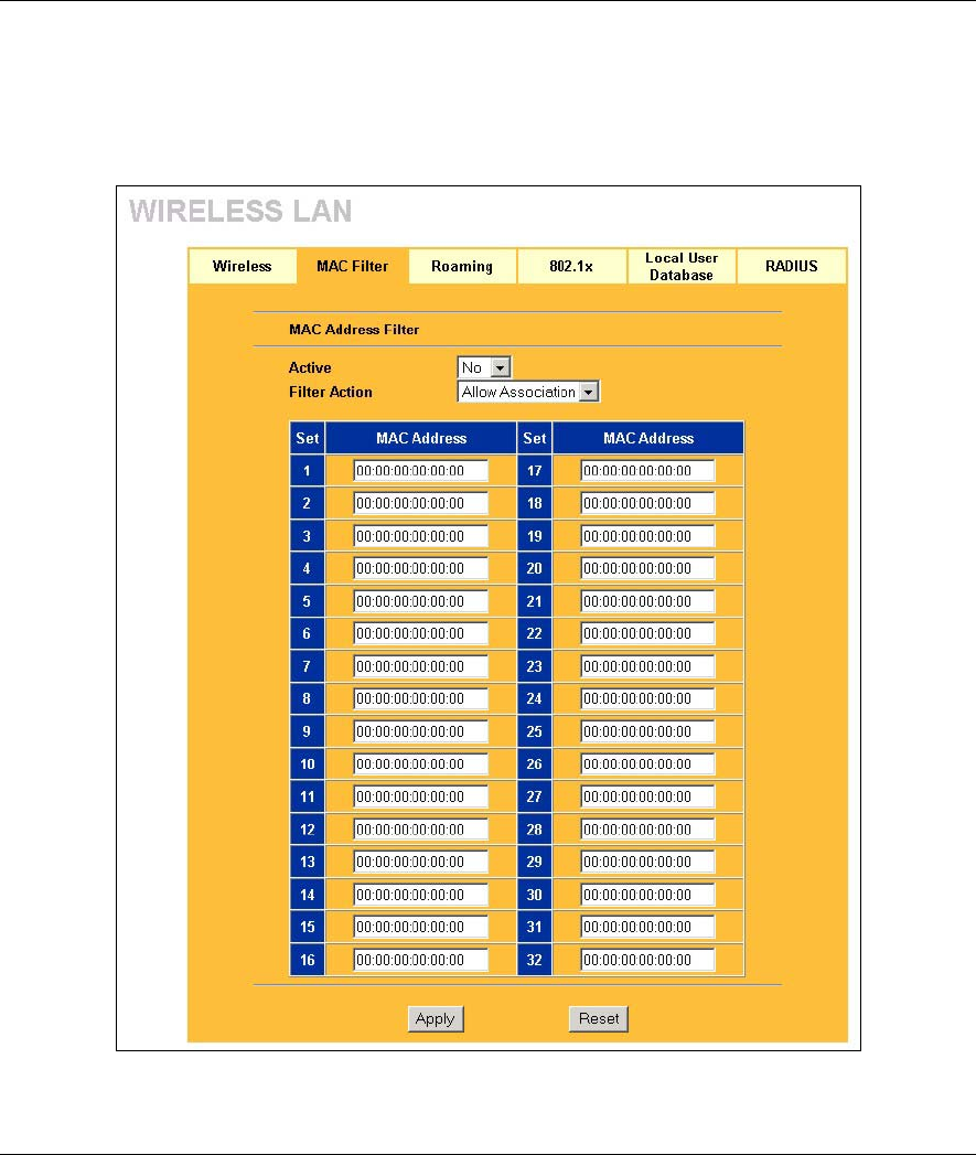
ZyAIR B-500 Wireless Access Point User’s Guide
Wireless Security 6-5
Ethernet device has a unique MAC (Media Access Control) address. The MAC address is assigned at the
factory and consists of six pairs of hexadecimal characters, for example, 00:A0:C5:00:00:02. You need to
know the MAC address of the devices to configure this screen.
To change your ZyAIR’s MAC Filter settings, click the WIRELESS link under ADVANCED and then the
MAC Filter tab. The screen appears as shown.
Figure 6-4 MAC Address Filter

ZyAIR B-500 Wireless Access Point User’s Guide
6-6 Wireless Security
The following table describes the labels in this screen.
Table 6-2 MAC Address Filter
LABEL DESCRIPTION
Active Select Yes from the drop down list box to enable MAC address filtering.
Filter Action Define the filter action for the list of MAC addresses in the MAC address filter table.
Select Deny Association to block access to the ZyAIR, MAC addresses not listed will be
allowed to access the ZyAIR.
Select Allow Association to permit access to the ZyAIR, MAC addresses not listed will be
denied access to the ZyAIR.
Set This is the index number of the MAC address.
MAC
Address Enter the MAC addresses (in XX:XX:XX:XX:XX:XX format) of the wireless station that are
allowed or denied access to the ZyAIR in these address fields.
Apply Click Apply to save your changes back to the ZyAIR.
Reset Click Reset to begin configuring this screen afresh.
6.5 802.1x Overview
The IEEE 802.1x standard outlines enhanced security methods for both the authentication of wireless stations
and encryption key management. Authentication can be done using the local user database internal to the
ZyAIR (authenticate up to 32 users) or an external RADIUS server for an unlimited number of users.
6.6 Introduction to RADIUS
RADIUS is based on a client-sever model that supports authentication and accounting, where access point is
the client and the server is the RADIUS server. The RADIUS server handles the following tasks among
others:
• Authentication
Determines the identity of the users.
• Accounting
Keeps track of the client’s network activity.
RADIUS user is a simple package exchange in which your ZyAIR acts as a message relay between the
wireless station and the network RADIUS server.

ZyAIR B-500 Wireless Access Point User’s Guide
Wireless Security 6-7
Types of RADIUS Messages
The following types of RADIUS messages are exchanged between the access point and the RADIUS server
for user authentication:
• Access-Request
Sent by an access point requesting authentication.
• Access-Reject
Sent by a RADIUS server rejecting access.
• Access-Accept
Sent by a RADIUS server allowing access.
• Access-Challenge
Sent by a RADIUS server requesting more information in order to allow access. The access point
sends a proper response from the user and then sends another Access-Request message.
The following types of RADIUS messages are exchanged between the access point and the RADIUS server
for user accounting:
• Accounting-Request
Sent by the access point requesting accounting.
• Accounting-Response
Sent by the RADIUS server to indicate that it has started or stopped accounting.
In order to ensure network security, the access point and the RADIUS server use a shared secret key, which
is a password, they both know. The key is not sent over the network. In addition to the shared key, password
information exchanged is also encrypted to protect the wired network from unauthorized access.
6.6.1 EAP Authentication Overview
EAP (Extensible Authentication Protocol) is an authentication protocol that runs on top of the IEEE802.1x
transport mechanism in order to support multiple types of user authentication. By using EAP to interact with
an EAP-compatible RADIUS server, the access point helps a wireless station and a RADIUS server perform
authentication.
The type of authentication you use depends on the RADIUS server or the AP. The ZyAIR supports EAP-
TLS, EAP-TTLS and DEAP with RADIUS. Refer to the Types of EAP Authentication appendix for
descriptions on the four common types.
Your ZyAIR supports EAP-MD5 (Message-Digest Algorithm 5) with the local user database and RADIUS.
The following figure shows an overview of authentication when you specify a RADIUS server on your
access point.
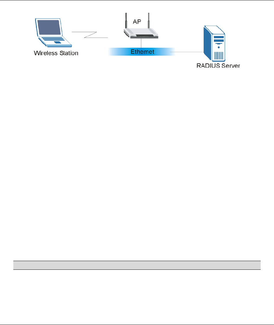
ZyAIR B-500 Wireless Access Point User’s Guide
6-8 Wireless Security
Figure 6-5 EAP Authentication
The details below provide a general description of how IEEE 802.1x EAP authentication works. For an
example list of EAP-MD5 authentication steps, see the IEEE 802.1x appendix.
• The wireless station sends a “start” message to the ZyAIR.
• The ZyAIR sends a “request identity” message to the wireless station for identity information.
• The wireless station replies with identity information, including username and password.
• The RADIUS server checks the user information against its user profile database and determines
whether or not to authenticate the wireless station.
6.7 Dynamic WEP Key Exchange
The AP maps a unique key that is generated with the RADIUS server. This key expires when the wireless
connection times out, disconnects or reauthentication times out. A new WEP key is generated each time
reauthentication is performed.
If this feature is enabled, it is not necessary to configure a default WEP encryption key in the Wireless
screen. You may still configure and store keys here, but they will not be used while Dynamic WEP is
enabled.
To use Dynamic WEP, enable and configure the RADIUS server (see section 6.11) and enable Dynamic
WEP Key Exchange in the 802.1x screen. Ensure that the wireless station’s EAP type is configured to one of
the following:
• EAP-TLS
• EAP-TTLS
• PEAP
EAP-MD5 cannot be used with Dynamic WEP Key Exchange.
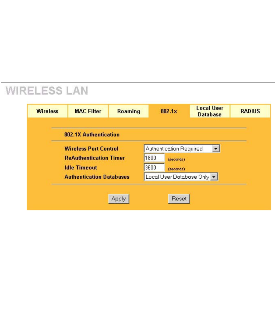
ZyAIR B-500 Wireless Access Point User’s Guide
Wireless Security 6-9
6.8 Introduction to Local User Database
By storing user profiles locally on the ZyAIR, your ZyAIR is able to authenticate wireless users without
interacting with a network RADIUS server. However, there is a limit on the number of users you may
authenticate in this way.
6.9 Configuring 802.1x
To change your ZyAIR’s authentication settings, click the WIRELESS link under ADVANCED and then
the 802.1x tab. The screen appears as shown.
Figure 6-6 802.1x Authentication
The following table describes the labels in this screen.

ZyAIR B-500 Wireless Access Point User’s Guide
6-10 Wireless Security
Table 6-3 802.1x Authentication
LABEL DESCRIPTION
Wireless Port
Control
To control wireless stations access to the wired network, select a control method from
the drop-down list box. Choose from No Authentication Required, Authentication
Required and No Access Allowed.
No Authentication Required allows all wireless stations access to the wired network
without entering usernames and passwords. This is the default setting.
Authentication Required means that all wireless stations have to enter usernames
and passwords before access to the wired network is allowed.
No Access Allowed blocks all wireless stations access to the wired network.
ReAuthentication
Timer
(seconds)
Specify how often wireless stations have to reenter usernames and passwords in
order to stay connected. This field is activated only when you select Authentication
Required in the Wireless Port Control field.
Enter a time interval between 10 and 9999 seconds. The default time interval is 1800
seconds (30 minutes).
If wireless station authentication is done using a RADIUS
server, the reauthentication timer on the RADIUS server has
priority.
Idle Timeout
(seconds)
The ZyAIR automatically disconnects a wireless station from the wired network after
a period of inactivity. The wireless station needs to enter the username and password
again before access to the wired network is allowed.
This field is activated only when you select Authentication Required in the Wireless
Port Control field. The default time interval is 3600 seconds (1 hour).

ZyAIR B-500 Wireless Access Point User’s Guide
Wireless Security 6-11
Table 6-3 802.1x Authentication
LABEL DESCRIPTION
Authentication
Databases
This field is activated only when you select Authentication Required in the Wireless
Port Control field.
The authentication database contains wireless station login information. The local
user database is the built-in database on the ZyAIR. The RADIUS is an external
server. Use this drop-down list box to select which database the ZyAIR should use
(first) to authenticate a wireless station.
Before you specify the priority, make sure you have set up the corresponding
database correctly first.
Select Local User Database Only to have the ZyAIR just check the built-in user
database on the ZyAIR for a wireless station's username and password.
Select RADIUS Only to have the ZyAIR just check the user database on the
specified RADIUS server for a wireless station's username and password.
Select Local first, then RADIUS to have the ZyAIR first check the user database on
the ZyAIR for a wireless station's username and password. If the user name is not
found, the ZyAIR then checks the user database on the specified RADIUS server.
Select RADIUS first, then Local to have the ZyAIR first check the user database on
the specified RADIUS server for a wireless station's username and password. If the
ZyAIR cannot reach the RADIUS server, the ZyAIR then checks the local user
database on the ZyAIR. When the user name is not found or password does not
match in the RADIUS server, the ZyAIR will not check the local user database and
the authentication fails.
Apply Click Apply to save your changes back to the ZyAIR.
Reset Click Reset to begin configuring this screen afresh.
Once you enable user authentication, you need to specify an external RADIUS
server or create local user accounts on the ZyAIR for authentication.
6.10 Configuring Local User Database
To change your ZyAIR’s local user database, click the WIRELESS link under ADVANCED and then the
Local User Database tab. The screen appears as shown.
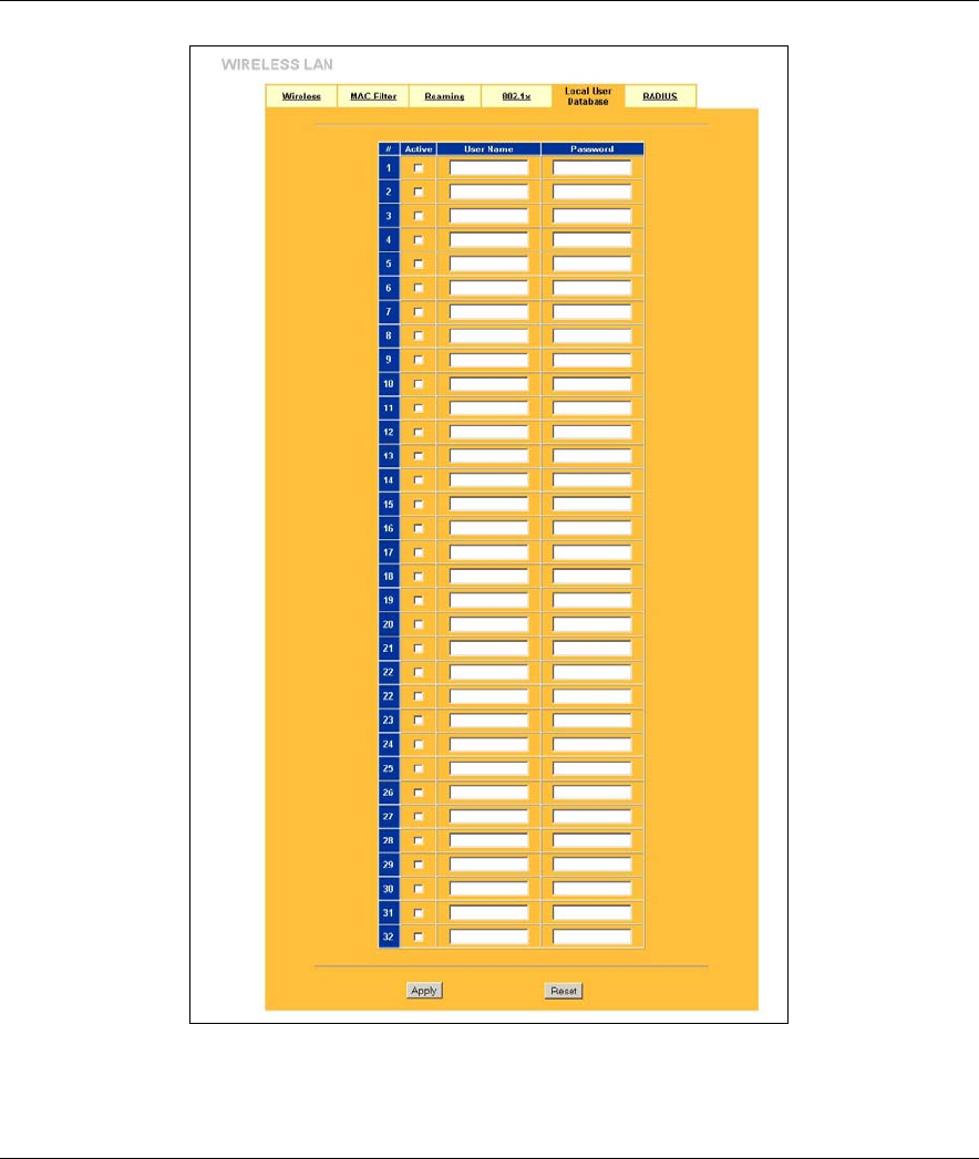
ZyAIR B-500 Wireless Access Point User’s Guide
6-12 Wireless Security
Figure 6-7 Local User Database
The following table describes the labels in this screen.
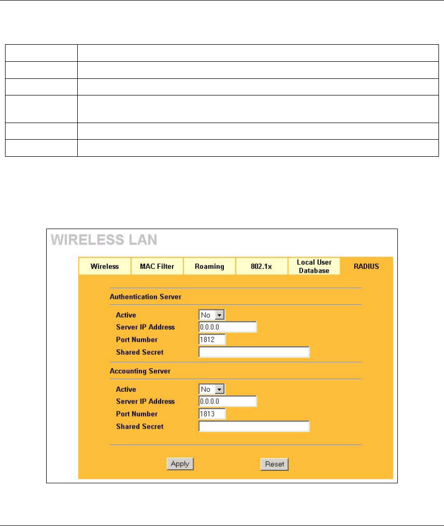
ZyAIR B-500 Wireless Access Point User’s Guide
Wireless Security 6-13
Table 6-4 Local User Database
LABEL DESCRIPTION
Active Select this check box to activate the user profile.
User Name Enter the username (up to 31 characters) for this user profile.
Password Type a password (up to 31 characters) for this user profile. Note that as you type a
password, the screen displays a (*) for each character you type.
Apply Click Apply to save your changes back to the ZyAIR.
Reset Click Reset to begin configuring this screen afresh.
6.11 Configuring RADIUS
Configure the RADIUS screen if you want to authenticate wireless users using an external server.
To set up your ZyAIR’s RADIUS server settings, click the WIRELESS link under ADVANCED and then
the RADIUS tab. The screen appears as shown.
Figure 6-8 RADIUS

ZyAIR B-500 Wireless Access Point User’s Guide
6-14 Wireless Security
The following table describes the labels in this screen.
Table 6-5 RADIUS
LABEL DESCRIPTION
Authentication Server
Active Select Yes from the drop-down list box to enable user authentication through an
external authentication server.
Select No to enable user authentication using the local user profile on the ZyAIR.
Server IP Address Enter the IP address of the external authentication server in dotted decimal
notation.
Port Number Enter the port number of the external authentication server. The default port
number is 1812.
You need not change this value unless your network administrator instructs you
to do so with additional information.
Shared Secret Enter a password (up to 31 alphanumeric characters) as the key to be shared
between the external authentication server and the ZyAIR.
The key must be the same on the external authentication server and your ZyAIR.
The key is not sent over the network.
Accounting Server
Active Select Yes from the drop down list box to enable user accounting through an
external authentication server.
Server IP Address Enter the IP address of the external accounting server in dotted decimal notation.
Port Number Enter the port number of the external accounting server. The default port number
is 1813.
You need not change this value unless your network administrator instructs you
to do so with additional information.
Shared Secret Enter a password (up to 31 alphanumeric characters) as the key to be shared
between the external authentication server and the ZyAIR.
The key must be the same on the external authentication server and your ZyAIR.
The key is not sent over the network.
Apply Click Apply to save your changes back to the ZyAIR.
Reset Click Reset to begin configuring this screen afresh.

ZyAIR B-500 Wireless Access Point User’s Guide
IP 7-1
Chapter 7
IP Screen
This chapter discusses how to configure IP on the ZyAIR
7.1 Factory Ethernet Defaults
The Ethernet parameters of the ZyAIR are preset in the factory with the following values:
• IP address of 192.168.1.2
• Subnet mask of 255.255.255.0 (24 bits)
These parameters should work for the majority of installations.
7.2 TCP/IP Parameters
7.2.1 IP Address and Subnet Mask
Refer to the section on IP address and subnet mask in the Wizard Setup chapter for this information.
7.3 Configuring IP
Click IP to display the screen shown next.
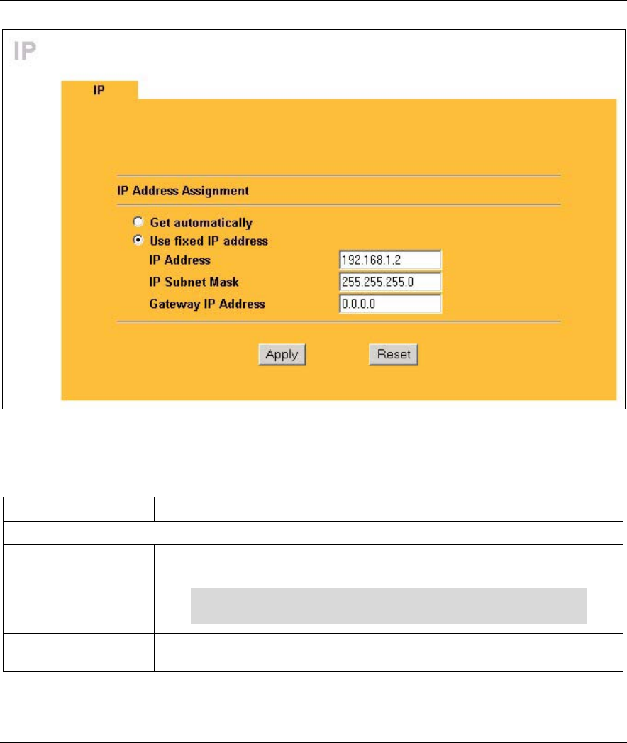
ZyAIR B-500 Wireless Access Point User’s Guide
7-2 IP
Figure 7-1 IP Setup
The following table describes the labels in this screen.
Table 7-1 IP Setup
LABEL DESCRIPTION
IP Address Assignment
Get automatically Select this option if your ZyAIR is using a dynamically assigned IP address from
a DHCP server each time.
You must know the IP address assigned to the ZyAIR (by
the DHCP server) to access the ZyAIR again.
Use fixed IP address Select this option if your ZyAIR is using a static IP address. When you select
this option, fill in the fields below.

ZyAIR B-500 Wireless Access Point User’s Guide
IP 7-3
Table 7-1 IP Setup
LABEL DESCRIPTION
IP Address Enter the IP address of your ZyAIR in dotted decimal notation.
If you change the ZyAIR's IP address, you must use the
new IP address if you want to access the web
configurator again.
IP Subnet Mask Enter the subnet mask.
Gateway IP Address Enter the IP address of a gateway. The gateway is an immediate neighbor of
your ZyAIR that will forward the packet to the destination. On the LAN, the
gateway must be a router on the same segment as your ZyAIR; over the WAN,
the gateway must be the IP address of one of the remote node.
Apply Click Apply to save your changes back to the ZyAIR.
Reset Click Reset to begin configuring this screen afresh.

Logs
III
Part III:
LOGS
This part provides information and configuration instructions for the logs.
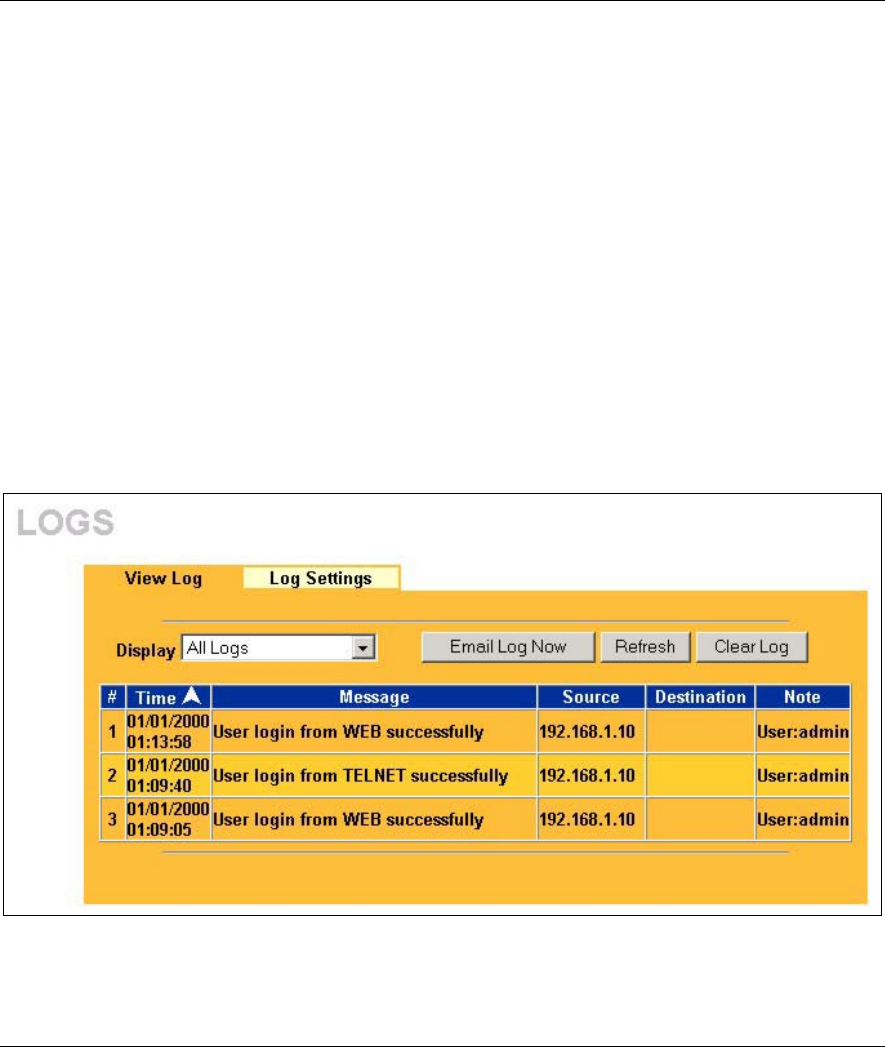
ZyAIR B-500 Wireless Access Point User’s Guide
Logs Screens 8-1
Chapter 8
Logs Screens
This chapter contains information about configuring general log settings and viewing the ZyAIR’s
logs. Refer to the appendix for example log message explanations.
8.1 Configuring View Log
The web configurator allows you to look at all of the ZyAIR’s logs in one location.
Click LOGS to open the View Log screen. Use the View Log screen to see the logs for the categories that
you selected in the Log Settings screen (see section 8.2). Options include logs about system maintenance,
system errors and access control.
You can view logs and alert messages in this page. Once the log entries are all used, the log will wrap around
and the old logs will be deleted.
Click a column heading to sort the entries. A triangle indicates the direction of the sort order.
Figure 8-1 View Log

ZyAIR B-500 Wireless Access Point User’s Guide
8-2 Logs Screens
The following table describes the labels in this screen.
Table 8-1 View Log
LABEL DESCRIPTION
Display Select a log category from the drop down list box to display logs within the selected
category. To view all logs, select All Logs.
The number of categories shown in the drop down list box depends on the selection in
the Log Settings page.
Time This field displays the time the log was recorded.
Message This field states the reason for the log.
Source This field lists the source IP address of the incoming packet.
Destination This field lists the destination IP address of the incoming packet.
Note This field displays additional information about the log entry.
Email Log Now Click Email Log Now to send the log screen to the e-mail address specified in the Log
Settings page.
Refresh Click Refresh to renew the log screen.
Clear Log Click Clear Log to clear all the logs.
8.2 Configuring Log Settings
To change your ZyAIR’s log settings, click LOGS and then the Log Settings tab. The screen appears as
shown.
Use the Log Settings screen to configure to where the ZyAIR is to send the logs; the schedule for when the
ZyAIR is to send the logs and which logs and/or immediate alerts the ZyAIR is to send.
An alert is a type of log that warrants more serious attention. Some categories such as System Errors consist
of both logs and alerts. You may differentiate them by their color in the View Log screen. Alerts are
displayed in red and logs are displayed in black.
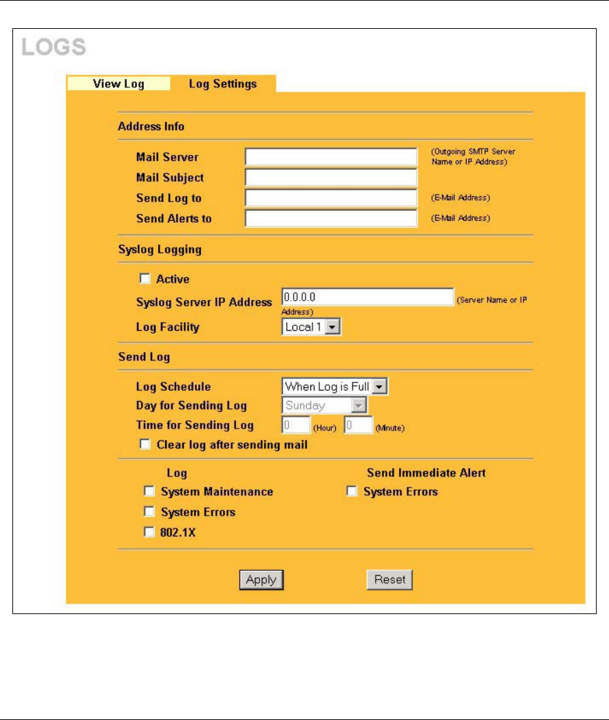
ZyAIR B-500 Wireless Access Point User’s Guide
Logs Screens 8-3
Figure 8-2 Log Settings
The following table describes the labels in this screen.

ZyAIR B-500 Wireless Access Point User’s Guide
8-4 Logs Screens
Table 8-2 Log Settings
LABEL DESCRIPTION
Address Info
Mail Server Enter the server name or the IP address of the mail server for the e-mail addresses
specified below. If this field is left blank, logs and alert messages will not be sent via
e-mail.
Mail Subject Type a title that you want to be in the subject line of the log e-mail message that the
ZyAIR sends.
Send Log to Logs are sent to the e-mail address specified in this field. If this field is left blank,
logs will not be sent via e-mail.
Send Alerts to Enter the e-mail address where the alert messages will be sent. If this field is left
blank, alert messages will not be sent via e-mail.
Syslog Logging Syslog logging sends a log to an external syslog server used to store logs.
Active Click Active to enable syslog logging.
Syslog Server IP
Address
Enter the server name or IP address of the syslog server that will log the selected
categories of logs.
Log Facility Select a location from the drop down list box. The log facility allows you to log the
messages to different files in the syslog server. Refer to the documentation of your
syslog program for more details.
Send Log
Log Schedule This drop-down menu is used to configure the frequency of log messages being
sent as E-mail:
• Daily
• Weekly
• Hourly
• When the Log is Full
• None.
If the Weekly or the Daily option is selected, specify a time of day when the E-mail
should be sent. If the Weekly option is selected, then also specify which day of the
week the E-mail should be sent. If the When Log is Full option is selected, an alert
is sent when the log fills up. If you select None, no log messages are sent.
Day for Sending Log This field is only available when you select Weekly in the Log Schedule field.
Use the drop down list box to select which day of the week to send the logs.
Time for Sending Log Enter the time of the day in 24-hour format (for example 23:00 equals 11:00 pm) to
send the logs.

ZyAIR B-500 Wireless Access Point User’s Guide
Logs Screens 8-5
Table 8-2 Log Settings
LABEL DESCRIPTION
Clear log after sanding
mail
Select the check box to clear all logs after logs and alert messages are sent via e-
mail.
Log Select the categories of logs that you want to record.
Send Immediate Alert Select the categories of alerts for which you want the ZyAIR to immediately send
e-mail alerts.
Apply Click Apply to save your customized settings and exit this screen.
Reset Click Reset to reconfigure all the fields in this screen.

Maintenance
IV
Part IV:
MAINTENANCE
This part describes the Maintenance web configurator screens.
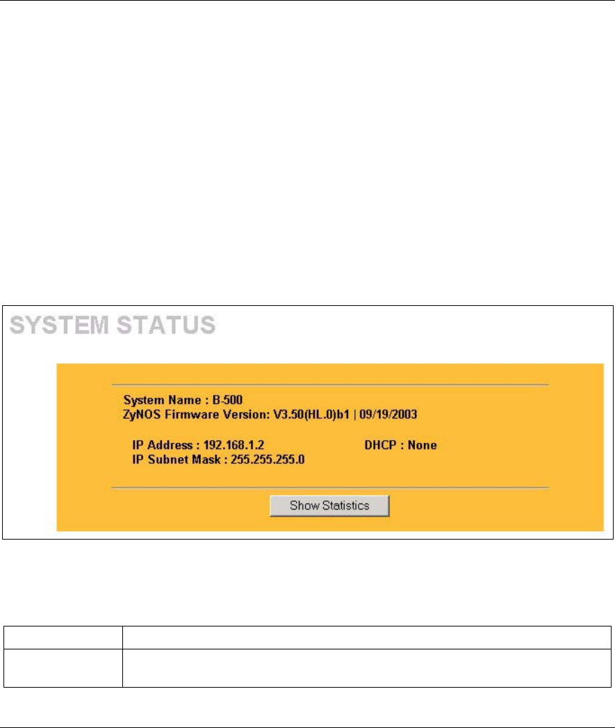
ZyAIR B-500 Wireless Access Point User’s Guide
Maintenance 9-1
Chapter 9
Maintenance
This chapter describes the Maintenance screens that display system information such as ZyNOS
firmware, port IP addresses and port traffic statistics.
9.1 Maintenance Overview
The maintenance screens can help you view system information, upload new firmware, manage configuration
and restart your ZyAIR.
9.2 System Status Screen
Click System Status to display the screen, where you can use to monitor your ZyAIR. Note that these labels
are READ-ONLY and are meant to be used for diagnostic purposes.
Figure 9-1 System Status
The following table describes the labels in this screen.
Table 9-1 System Status
LABEL DESCRIPTION
System Name This is the System Name you enter in the first Internet Access Wizard screen. It is
for identification purposes
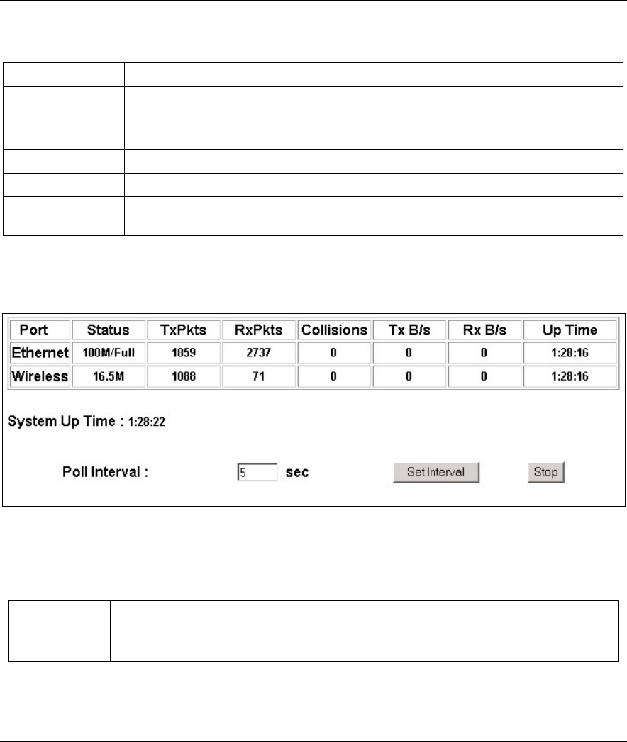
ZyAIR B-500 Wireless Access Point User’s Guide
9-2 Maintenance
Table 9-1 System Status
LABEL DESCRIPTION
ZyNOS Firmware
Version This is the ZyNOS Firmware version and the date created. ZyNOS is ZyXEL's
proprietary Network Operating System design.
IP Address This is the Ethernet port IP address.
IP Subnet Mask This is the Ethernet port subnet mask.
DHCP This is the Ethernet port DHCP role - Client or None.
Show Statistics Click Show Statistics to see performance statistics such as number of packets sent
and number of packets received for each port.
9.2.1 System Statistics
Read-only information here includes port status and packet specific statistics. Also provided are "system up
time" and "poll interval(s)". The Poll Interval field is configurable.
Figure 9-2 System Status: Show Statistics
The following table describes the labels in this screen.
Table 9-2 System Status: Show Statistics
LABEL DESCRIPTION
Port This is the Ethernet or wireless port.

ZyAIR B-500 Wireless Access Point User’s Guide
Maintenance 9-3
Table 9-2 System Status: Show Statistics
LABEL DESCRIPTION
Status This shows the port speed and duplex setting if you are using Ethernet encapsulation for
the Ethernet port.
This shows the transmission speed only for wireless port.
TxPkts This is the number of transmitted packets on this port.
RxPkts This is the number of received packets on this port.
Collisions This is the number of collisions on this port.
Tx B/s This shows the transmission speed in bytes per second on this port.
Rx B/s This shows the reception speed in bytes per second on this port.
Up Time This is total amount of time the line has been up.
System Up Time This is the total time the ZyAIR has been on.
Poll Interval Enter the time interval for refreshing statistics.
Set Interval Click this button to apply the new poll interval you entered above.
Stop Click this button to stop refreshing statistics.
9.3 Wireless Screen
9.3.1 Association List
View the wireless stations that are currently associated to the ZyAIR in the Association List screen.
Click the WIRELESS link under MAINTENANCE to display the screen as shown next.
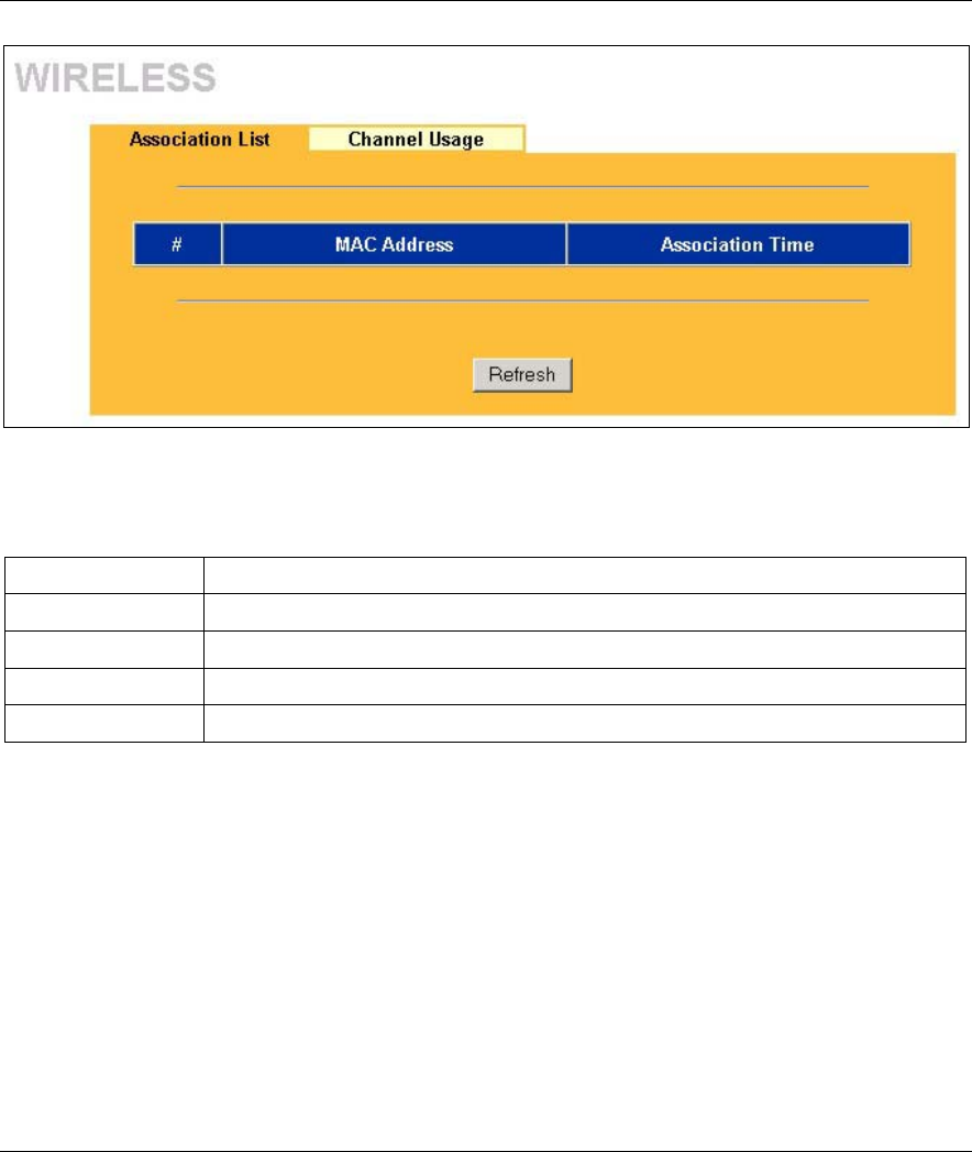
ZyAIR B-500 Wireless Access Point User’s Guide
9-4 Maintenance
Figure 9-3 Association List
The following table describes the labels in this screen.
Table 9-3 Association List
LABEL DESCRIPTION
# This is the index number of an associated wireless station.
MAC Address This field displays the MAC address of an associated wireless station.
Association Time This field displays the time a wireless station first associated with the ZyAIR.
Refresh Click Refresh to reload the screen.
9.3.2 Channel Usage
The Channel Usage screen shows whether a channel is used by another wireless network or not. If a channel
is being used, you should select a channel removed from it by five channels to completely avoid overlap.
Click the WIRELESS link under MAINTENANCE and then the Channel Usage tab to display the screen
as shown next.
Wait a moment while the ZyAIR compiles the information.
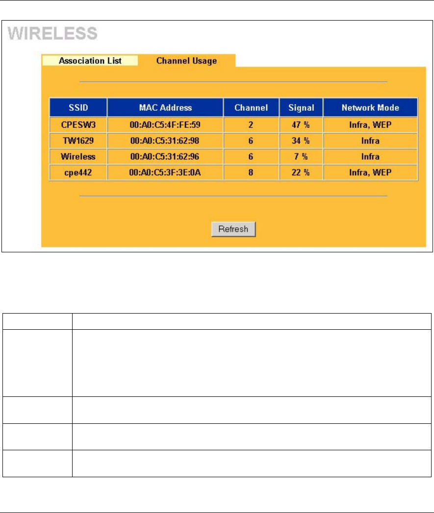
ZyAIR B-500 Wireless Access Point User’s Guide
Maintenance 9-5
Figure 9-4 Channel Usage
The following table describes the labels in this screen.
Table 9-4 Channel Usage
LABEL DESCRIPTION
SSID
This is the Service Set IDentification name of the AP in an Infrastructure wireless
network or wireless station in an Ad-Hoc wireless network. For our purposes, we define
an Infrastructure network as a wireless network that uses an AP and an Ad-Hoc network
(also known as Independent Basic Service Set (IBSS)) as one that doesn’t. See the
Wireless Configuration and Roaming chapter for more information on basic service sets
(BSS) and extended service sets (ESS).
MAC Address This field displays the MAC address of the AP in an Infrastructure wireless network. It is
randomly generated (so ignore it) in an Ad-Hoc wireless network.
Channel This is the index number of the channel currently used by the associated AP in an
Infrastructure wireless network or wireless stations in an Ad-Hoc wireless network.
Signal This field displays the strength of the AP’s signal. If you must choose a channel that’s
currently in use, choose one with low signal strength for minimum interference.
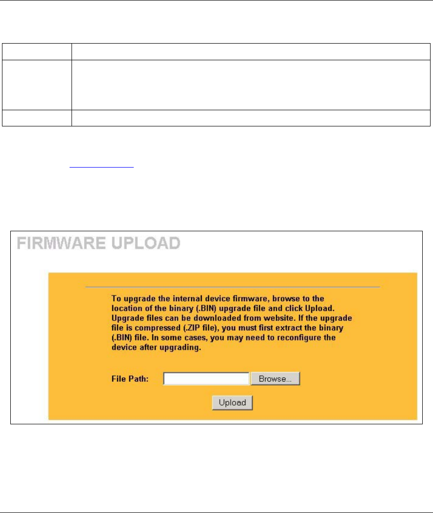
ZyAIR B-500 Wireless Access Point User’s Guide
9-6 Maintenance
Table 9-4 Channel Usage
LABEL DESCRIPTION
Network Mode
“Network mode” in this screen refers to your wireless LAN infrastructure (refer to the
Wireless LAN chapter) and WEP setup.
Network modes are: Infra (infrastructure), Infra, WEP (Infrastructure with WEP
encryption is enabled), Ad-Hoc, or Ad-Hoc, WEP.
Refresh Click Refresh to reload the screen.
9.4 F/W Upload Screen
Find firmware at www.zyxel.com in a file that (usually) uses the system model name with a "*.bin"
extension, e.g., "zyair.bin". The upload process uses HTTP (Hypertext Transfer Protocol) and may take up to
two minutes. After a successful upload, the system will reboot. See the Firmware and Configuration File
Maintenance chapter for upgrading firmware using FTP/TFTP commands.
Click F/W UPLOAD to display the screen as shown. Follow the instructions in this screen to upload
firmware to your ZyAIR.
Figure 9-5 Firmware Upload
The following table describes the labels in this screen.
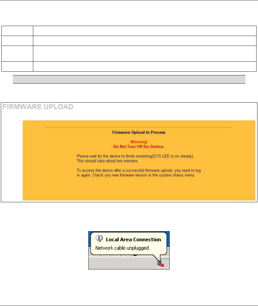
ZyAIR B-500 Wireless Access Point User’s Guide
Maintenance 9-7
Table 9-5 Firmware Upload
LABEL DESCRIPTION
File Path Type in the location of the file you want to upload in this field or click Browse ... to find it.
Browse... Click Browse... to find the .bin file you want to upload. Remember that you must decompress
compressed (.zip) files before you can upload them.
Upload Click Upload to begin the upload process. This process may take up to two minutes.
Do not turn off the device while firmware upload is in progress!
After you see the Firmware Upload in Process screen, wait two minutes before logging into the device
again.
Figure 9-6 Firmware Upload In Process
The ZyAIR automatically restarts in this time causing a temporary network disconnect. In some operating
systems, you may see the following icon on your desktop.
Figure 9-7 Network Temporarily Disconnected
After two minutes, log in again and check your new firmware version in the System Status screen.
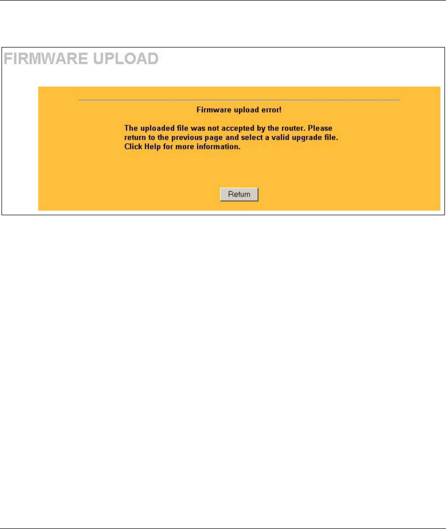
ZyAIR B-500 Wireless Access Point User’s Guide
9-8 Maintenance
If the upload was not successful, the following screen will appear. Click Return to go back to the F/W
Upload screen.
Figure 9-8 Firmware Upload Error
9.5 Configuration Screen
See the Firmware and Configuration File Maintenance chapter for transferring configuration files using
FTP/TFTP commands.
Click CONFIGURATION. Information related to backup configuration, restoring configuration and factory
defaults appears as shown next.
9.5.1 Backup Configuration
Backup Configuration allows you to backup (save) the current system (ZyAIR) configuration to your
computer. Backup is highly recommended once your ZyAIR is functioning properly.
Click Backup to save your current ZyAIR configuration to your computer.
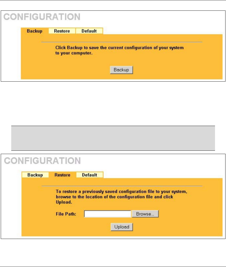
ZyAIR B-500 Wireless Access Point User’s Guide
Maintenance 9-9
Figure 9-9 Backup Configuration
9.5.2 Restore Configuration
Restore configuration replaces your ZyAIR's current configuration with a previously saved configuration.
Restore files (usually) have a .ROM extension, e.g., "zyair.rom". The system reboots automatically after the
file transfer is complete and uses the configured values in the file.
WARNING!
Do not interrupt the file transfer process as this may PERMANENTLY DAMAGE
YOUR ZyAIR. When the Restore Configuration process is complete, the ZyAIR will
automatically restart.
Figure 9-10 Restore Configuration
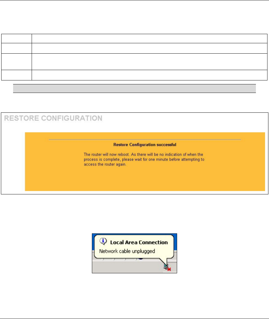
ZyAIR B-500 Wireless Access Point User’s Guide
9-10 Maintenance
The following table describes the labels in this screen.
Table 9-6 Restore Configuration
LABEL DESCRIPTION
File Path Type in the location of the file you want to upload in this field or click Browse ... to find it.
Browse... Click Browse... to find the file you want to upload. Remember that you must decompress
compressed (.ZIP) files before you can upload them.
Upload Click Upload to begin the upload process.
Do not turn off the device while configuration file upload is in progress.
After you see a “configuration upload successful” screen, you must then wait one minute before logging into
the ZyAIR again.
Figure 9-11 Configuration Upload Successful
The ZyAIR automatically restarts in this time causing a temporary network disconnect. In some operating
systems, you may see the following icon on your desktop.
Figure 9-12 Network Temporarily Disconnected
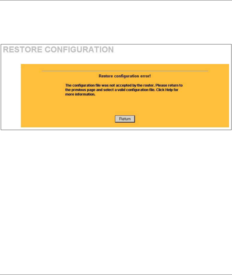
ZyAIR B-500 Wireless Access Point User’s Guide
Maintenance 9-11
If you uploaded the default configuration file you may need to change the IP address of your computer to be
in the same subnet as that of the default ZyAIR IP address (192.168.1.2). See the appendix for details on how
to set up your computer’s IP address.
If the upload was not successful, the following screen will appear. Click Return to go back to the
Configuration screen.
Figure 9-13 Configuration Upload Error
9.5.3 Back to Factory Defaults
Clicking the Reset button in this section clears all user-entered configuration information and returns the
ZyAIR to its factory defaults as shown on the screen. This will erase all configurations that you have applied.
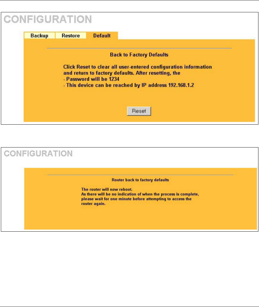
ZyAIR B-500 Wireless Access Point User’s Guide
9-12 Maintenance
Figure 9-14 Back to Factory Default
The following warning screen will appear.
Figure 9-15 Reset Warning Message
You can also press the RESET button on the rear panel to reset the factory defaults of your ZyAIR. Refer to
the Resetting the ZyAIR section for more information on the RESET button.