ZyXEL Communications G470 802.11g Wireless Ethernet Adapter User Manual ZyXEL G 220F User s Guide V1 00 Oct 2004
ZyXEL Communications Corporation 802.11g Wireless Ethernet Adapter ZyXEL G 220F User s Guide V1 00 Oct 2004
Contents
- 1. Manual Pt1
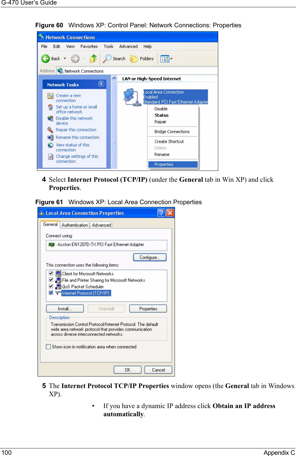
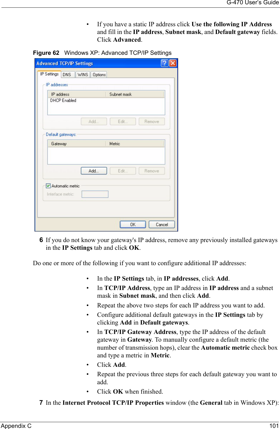
- 2. Manual Pt2
Manual Pt2
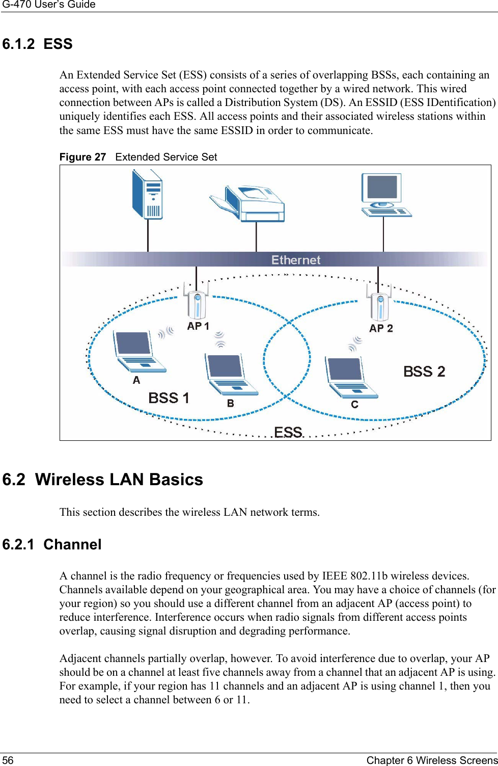
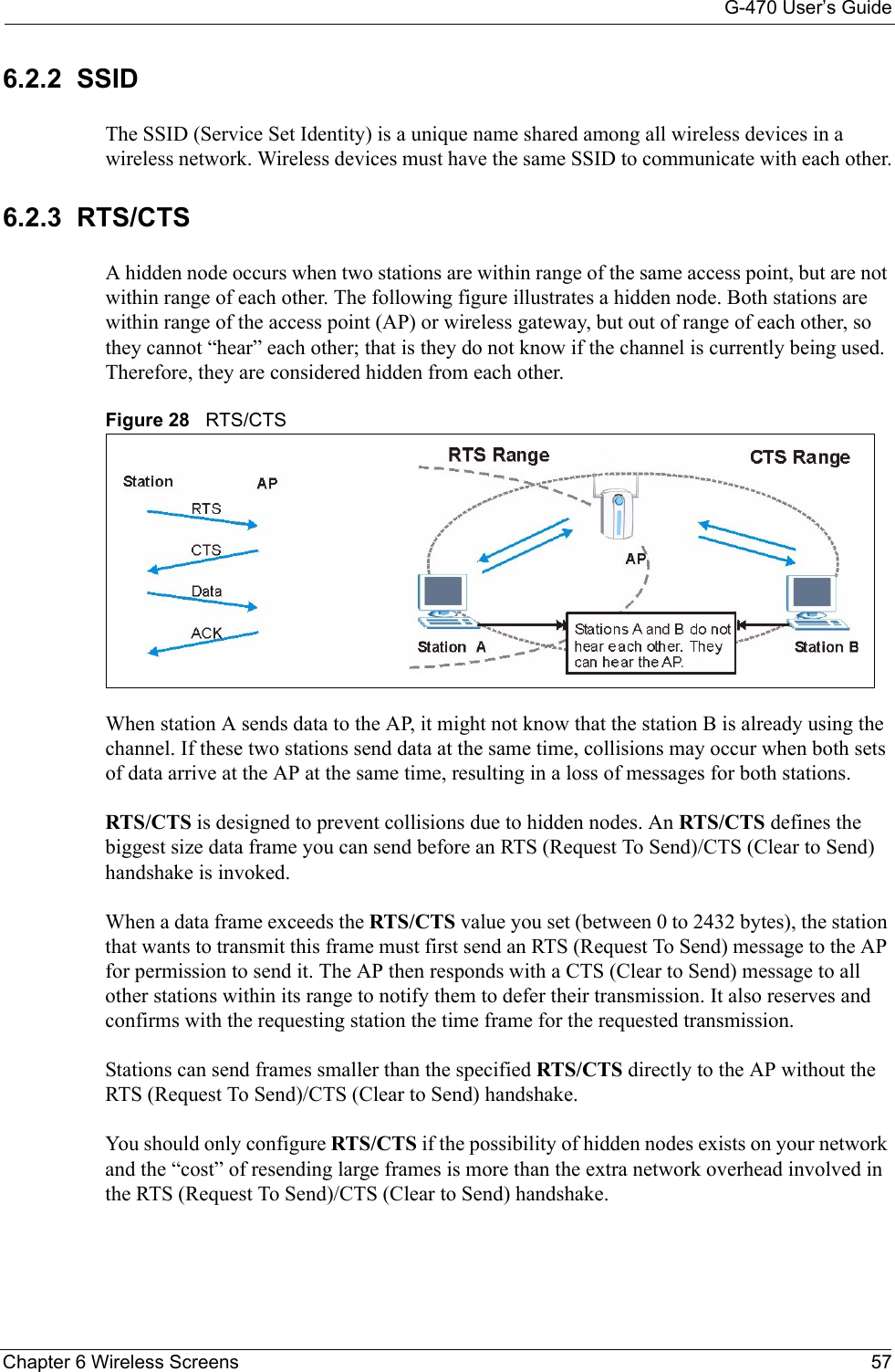
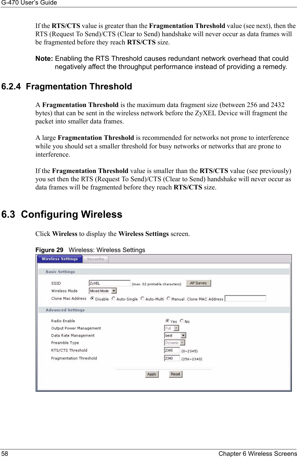
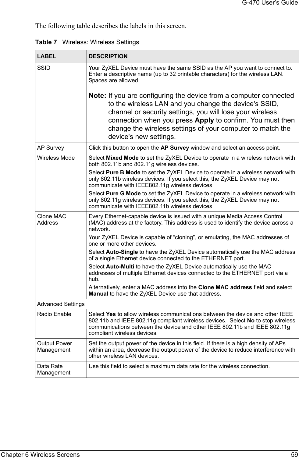
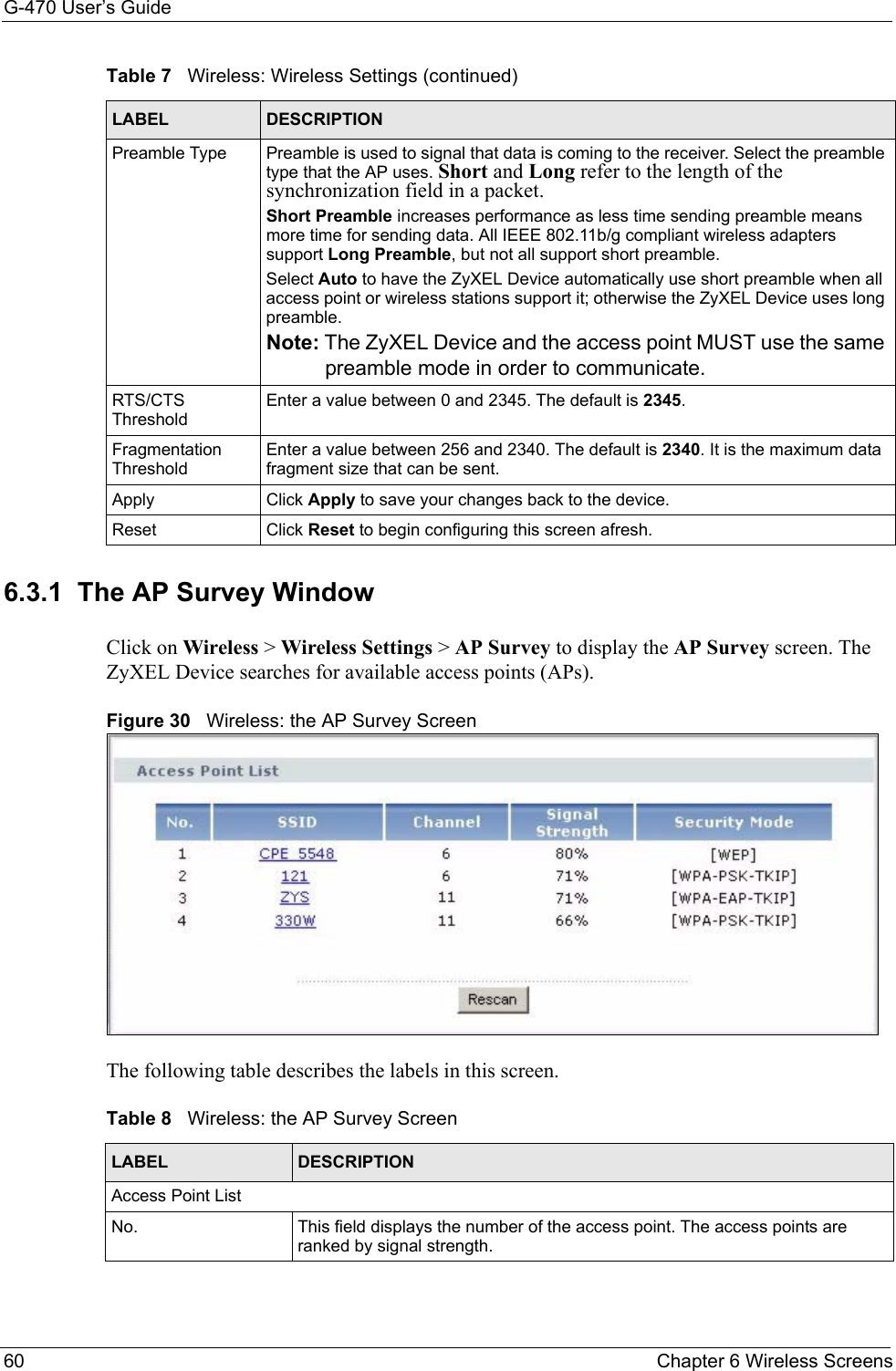

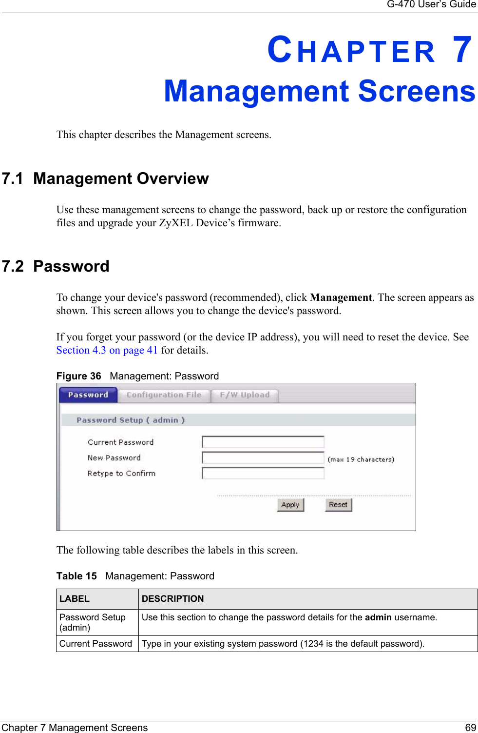
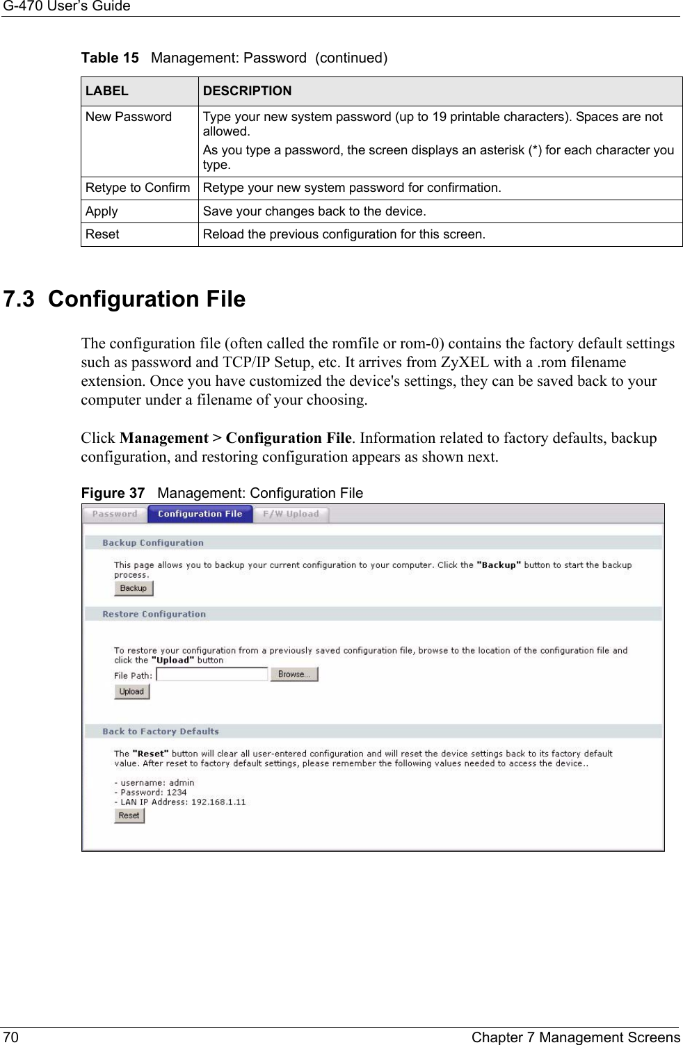
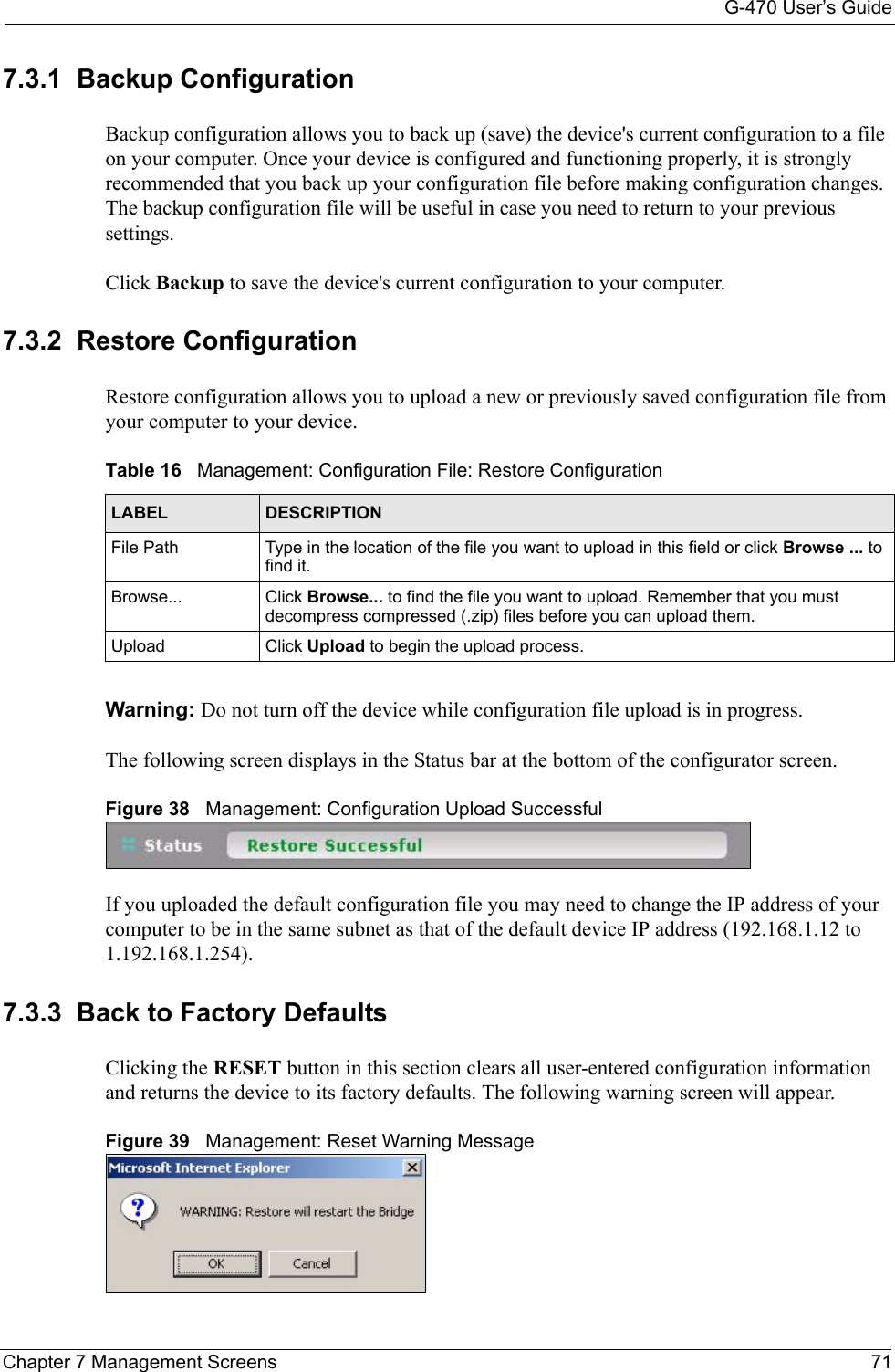
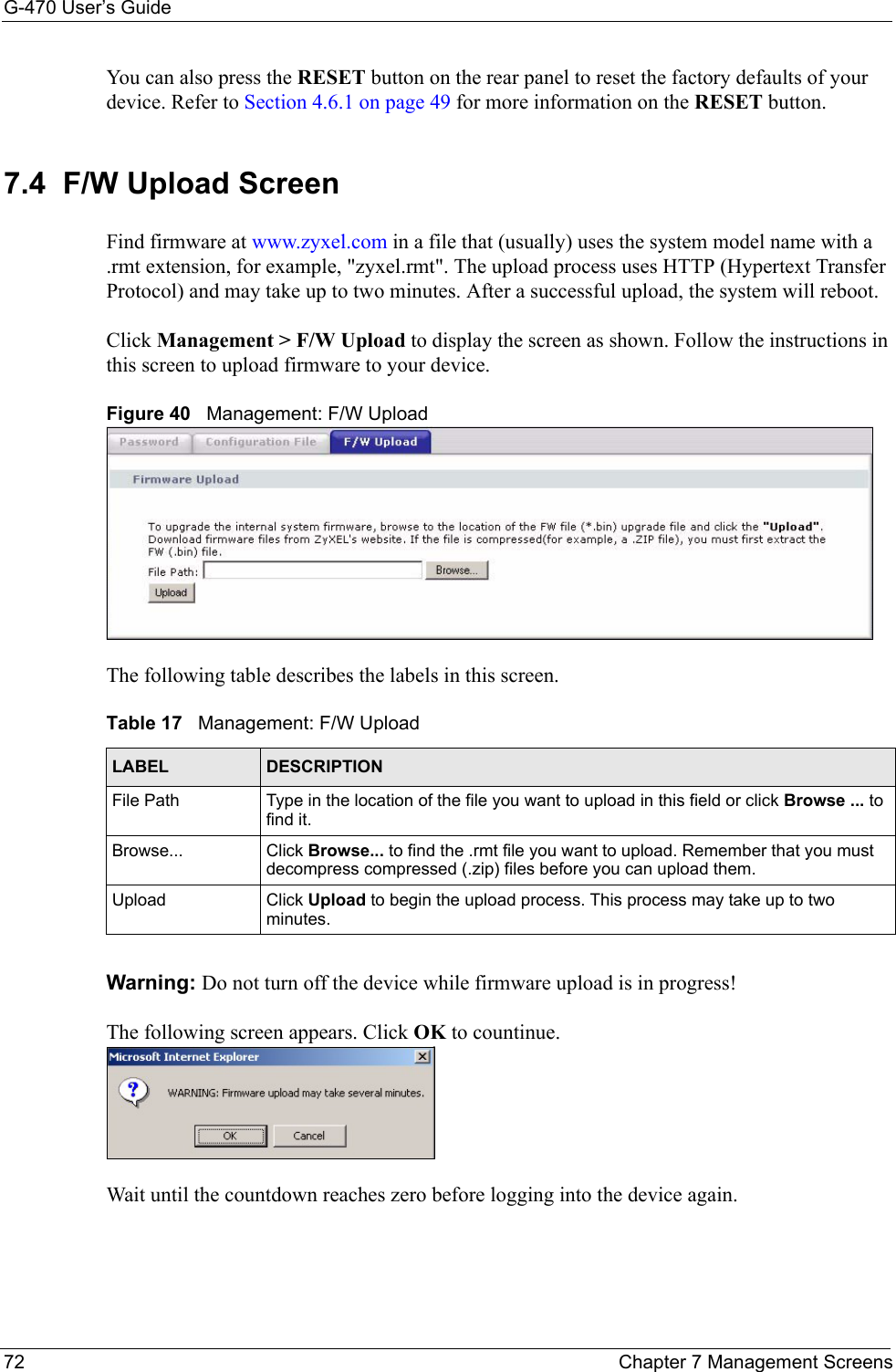

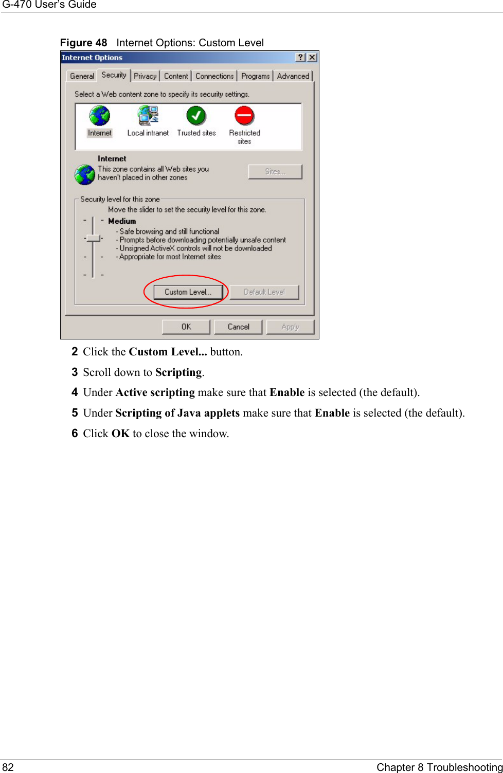
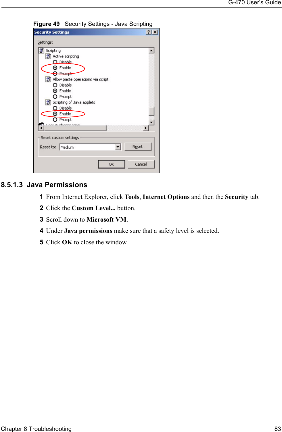
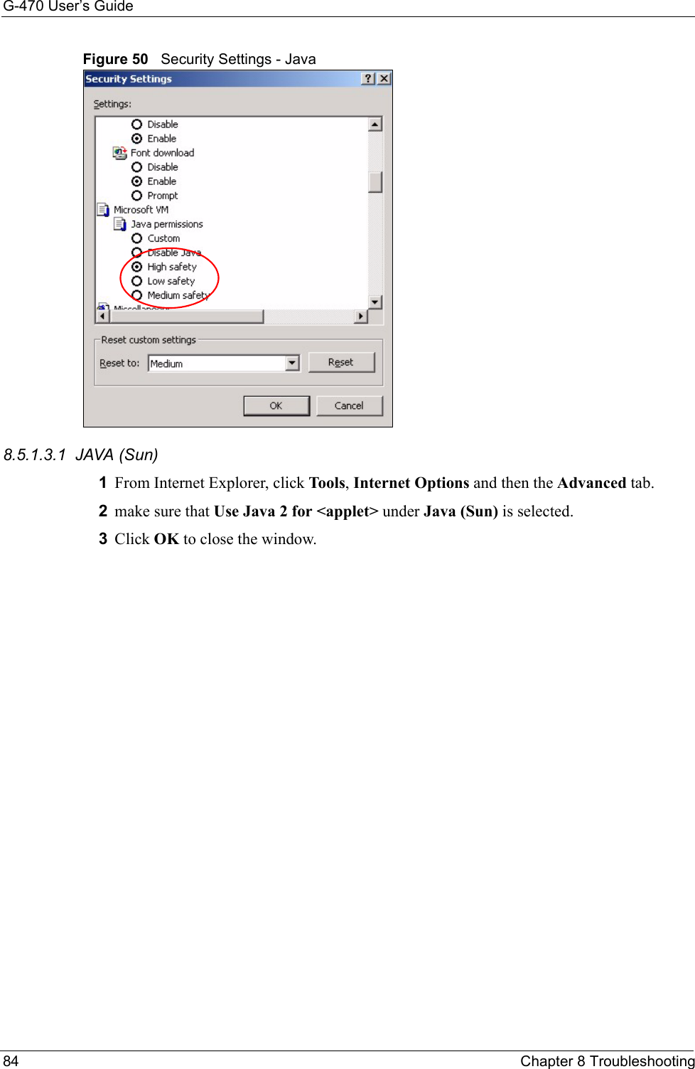
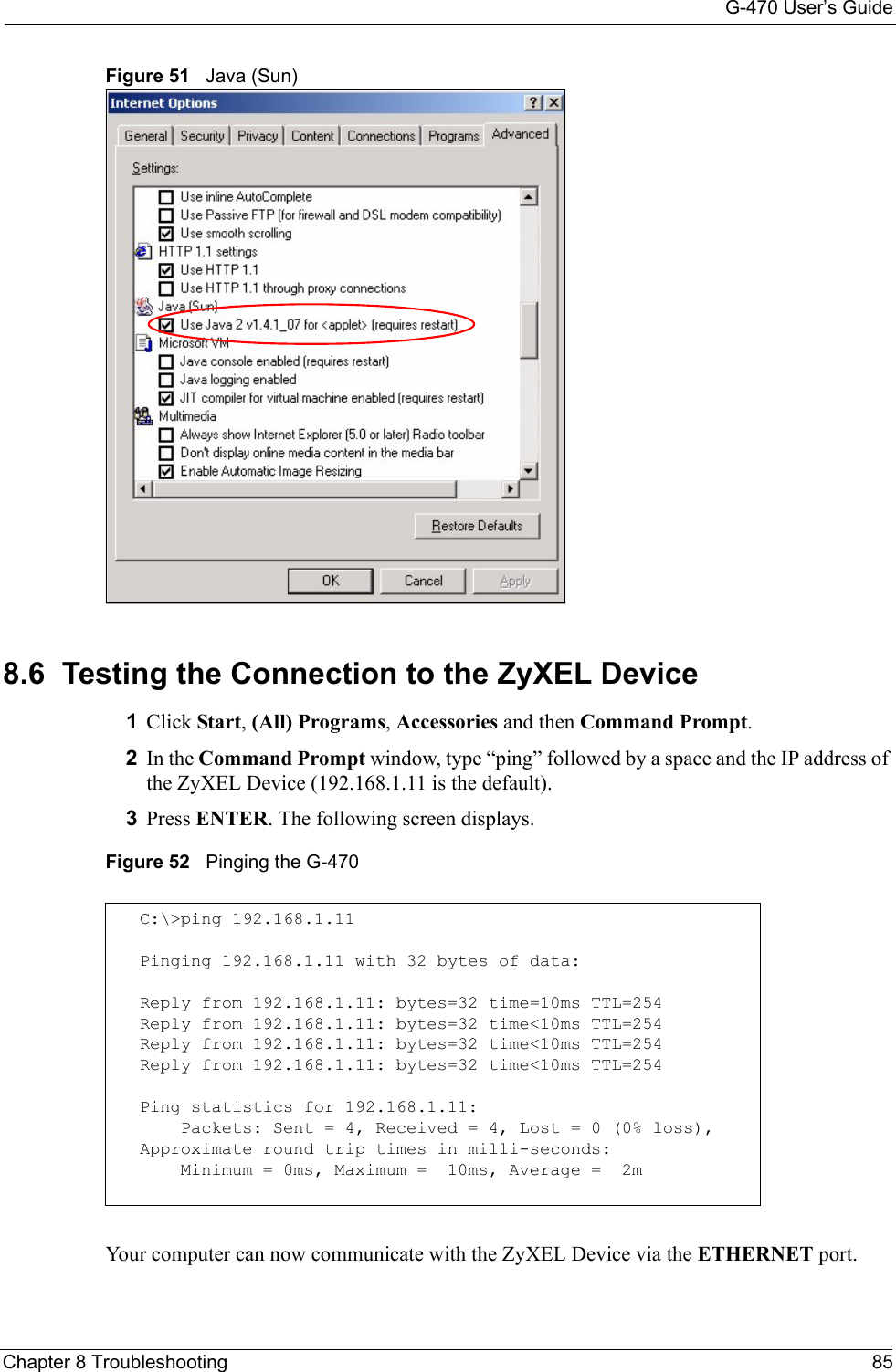


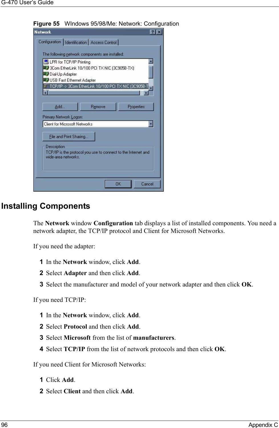
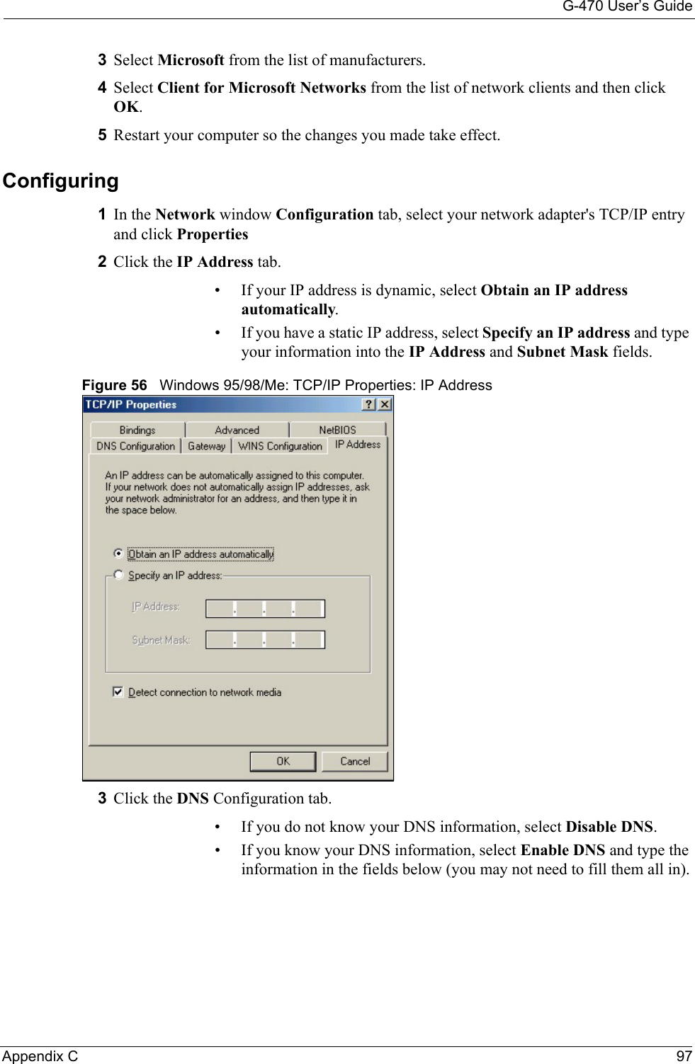
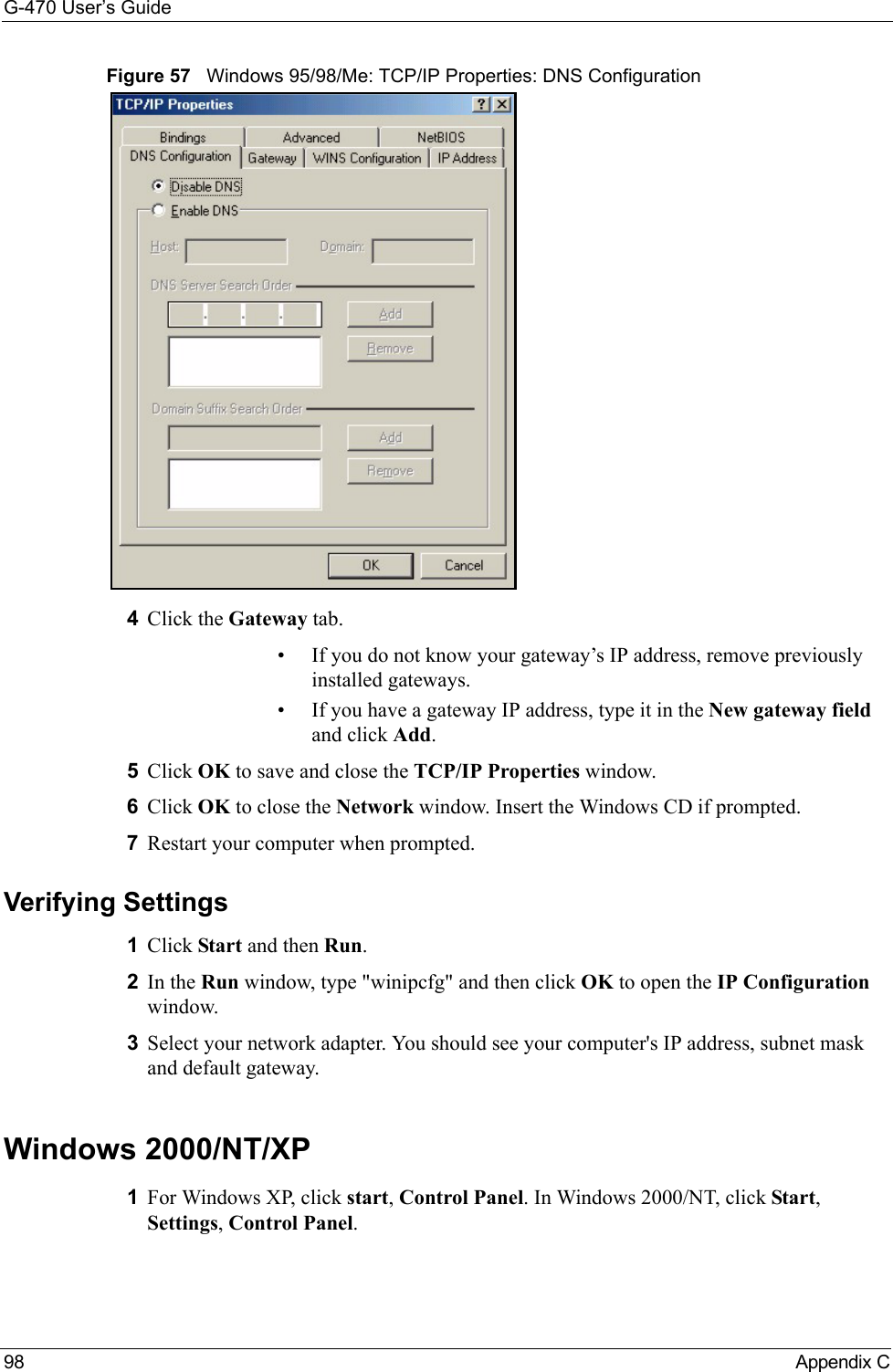
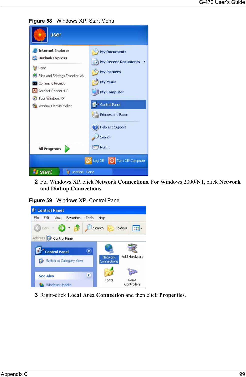
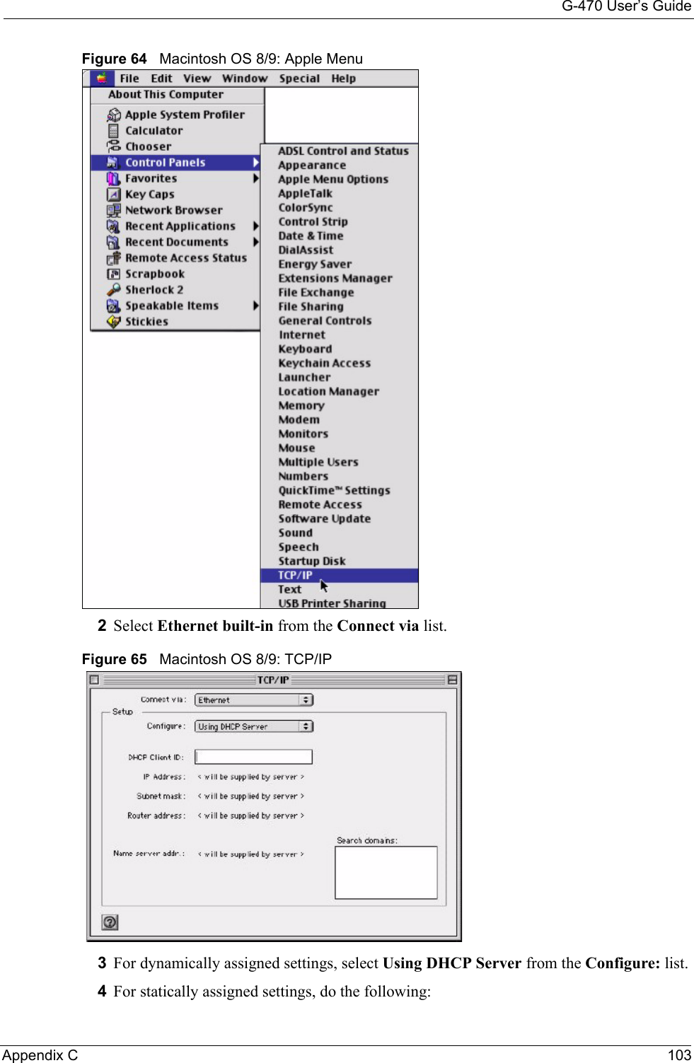
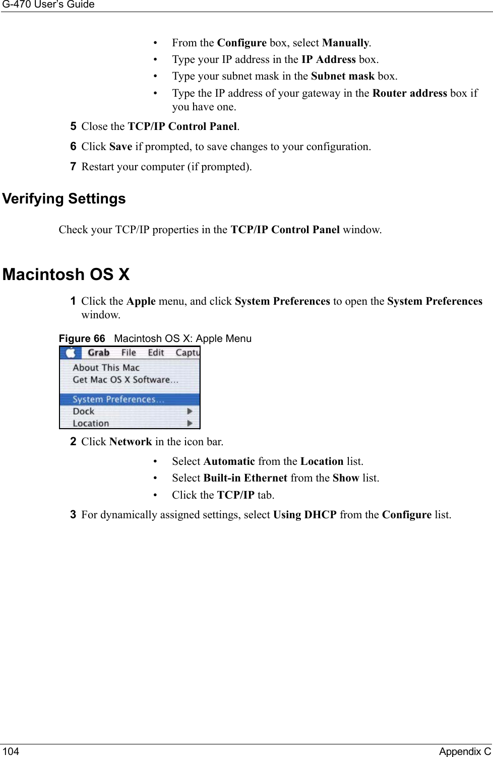
![G-470 User’s Guide102 Appendix C• Click Obtain DNS server address automatically if you do not know your DNS server IP address(es).• If you know your DNS server IP address(es), click Use the following DNS server addresses, and type them in the Preferred DNS server and Alternate DNS server fields. If you have previously configured DNS servers, click Advanced and then the DNS tab to order them.Figure 63 Windows XP: Internet Protocol (TCP/IP) Properties8Click OK to close the Internet Protocol (TCP/IP) Properties window.9Click OK to close the Local Area Connection Properties window.10Restart your computer (if prompted).Verifying Settings1Click Start, All Programs, Accessories and then Command Prompt.2In the Command Prompt window, type "ipconfig" and then press [ENTER]. You can also open Network Connections, right-click a network connection, click Status and then click the Support tab.Macintosh OS 8/9 1Click the Apple menu, Control Panel and double-click TCP/IP to open the TCP/IP Control Panel.](https://usermanual.wiki/ZyXEL-Communications/G470.Manual-Pt2/User-Guide-690708-Page-48.png)