ZyXEL Communications G470 802.11g Wireless Ethernet Adapter User Manual ZyXEL G 220F User s Guide V1 00 Oct 2004
ZyXEL Communications Corporation 802.11g Wireless Ethernet Adapter ZyXEL G 220F User s Guide V1 00 Oct 2004
Contents
- 1. Manual Pt1
- 2. Manual Pt2
Manual Pt2
G-470 User’s Guide
Chapter 6 Wireless Screens 55
CHAPTER 6
Wireless Screens
This chapter discusses how to configure wireless settings and wireless security on your
ZyXEL Device.
6.1 Wireless LAN Overview
This section introduces the wireless LAN (WLAN) and some basic scenarios.
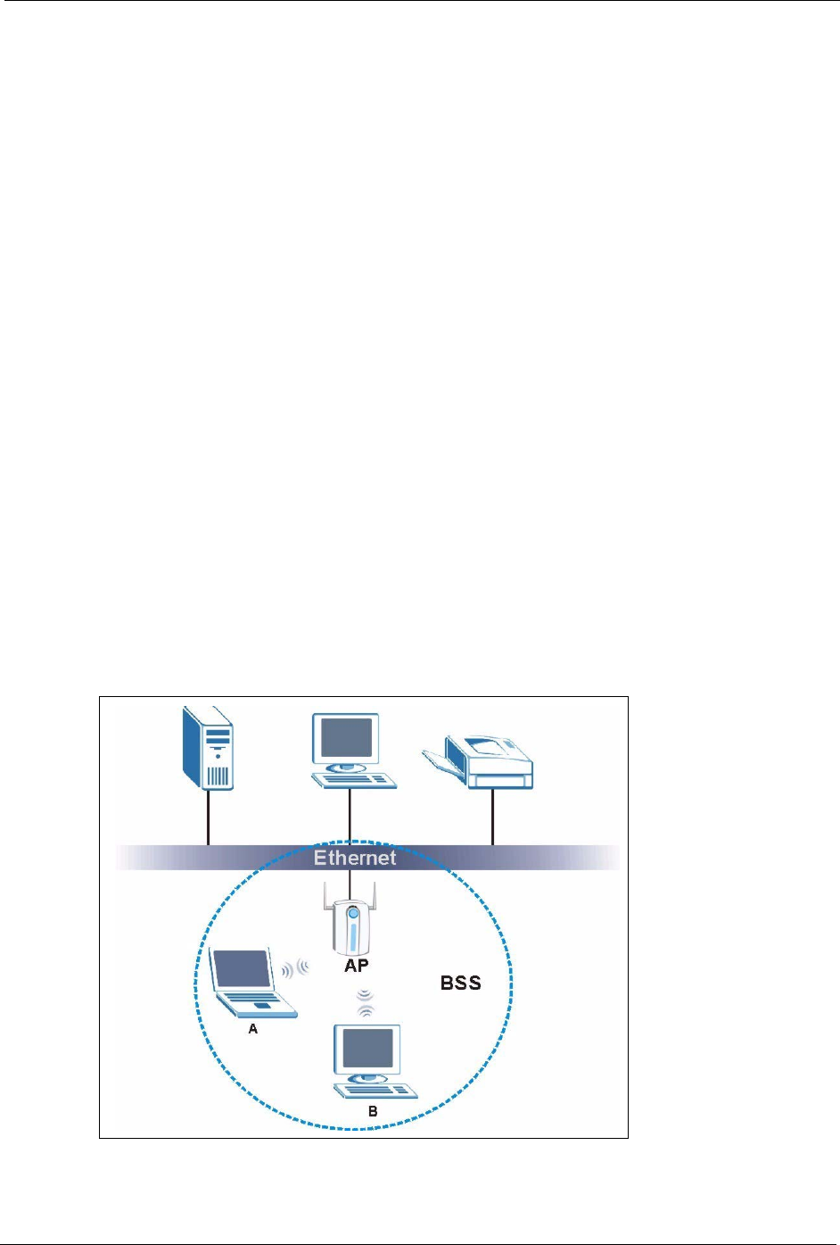
6.1.1 BSS (Infrastructure)
A Basic Service Set (BSS), also called an Infrastructure network, exists when all
communications between wireless stations or between a wireless station and a wired network
client go through one access point (AP).
Intra-BSS traffic is traffic between wireless stations in the BSS. When Intra-BSS is enabled,
wireless station A and B can access the wired network and communicate with each other.
When Intra-BSS is disabled, wireless station A and B can still access the wired network but
cannot communicate with each other.
Figure 26 Basic Service set
G-470 User’s Guide
56 Chapter 6 Wireless Screens
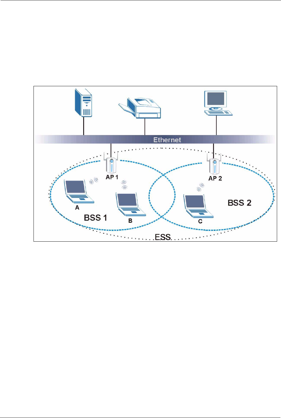
6.1.2 ESS
An Extended Service Set (ESS) consists of a series of overlapping BSSs, each containing an
access point, with each access point connected together by a wired network. This wired
connection between APs is called a Distribution System (DS). An ESSID (ESS IDentification)
uniquely identifies each ESS. All access points and their associated wireless stations within
the same ESS must have the same ESSID in order to communicate.
Figure 27 Extended Service Set
6.2 Wireless LAN Basics
This section describes the wireless LAN network terms.
6.2.1 Channel
A channel is the radio frequency or frequencies used by IEEE 802.11b wireless devices.
Channels available depend on your geographical area. You may have a choice of channels (for
your region) so you should use a different channel from an adjacent AP (access point) to
reduce interference. Interference occurs when radio signals from different access points
overlap, causing signal disruption and degrading performance.
Adjacent channels partially overlap, however. To avoid interference due to overlap, your AP
should be on a channel at least five channels away from a channel that an adjacent AP is using.
For example, if your region has 11 channels and an adjacent AP is using channel 1, then you
need to select a channel between 6 or 11.
G-470 User’s Guide
Chapter 6 Wireless Screens 57
6.2.2 SSID
The SSID (Service Set Identity) is a unique name shared among all wireless devices in a
wireless network. Wireless devices must have the same SSID to communicate with each other.
6.2.3 RTS/CTS
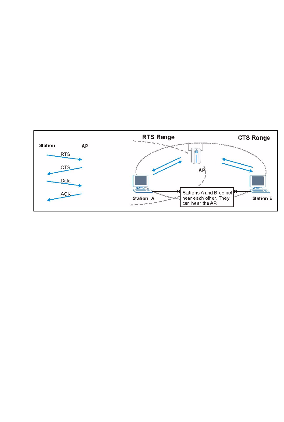
A hidden node occurs when two stations are within range of the same access point, but are not
within range of each other. The following figure illustrates a hidden node. Both stations are
within range of the access point (AP) or wireless gateway, but out of range of each other, so
they cannot “hear” each other; that is they do not know if the channel is currently being used.
Therefore, they are considered hidden from each other.
Figure 28 RTS/CTS
When station A sends data to the AP, it might not know that the station B is already using the
channel. If these two stations send data at the same time, collisions may occur when both sets
of data arrive at the AP at the same time, resulting in a loss of messages for both stations.
RTS/CTS is designed to prevent collisions due to hidden nodes. An RTS/CTS defines the
biggest size data frame you can send before an RTS (Request To Send)/CTS (Clear to Send)
handshake is invoked.
When a data frame exceeds the RTS/CTS value you set (between 0 to 2432 bytes), the station
that wants to transmit this frame must first send an RTS (Request To Send) message to the AP
for permission to send it. The AP then responds with a CTS (Clear to Send) message to all
other stations within its range to notify them to defer their transmission. It also reserves and
confirms with the requesting station the time frame for the requested transmission.
Stations can send frames smaller than the specified RTS/CTS directly to the AP without the
RTS (Request To Send)/CTS (Clear to Send) handshake.
You should only configure RTS/CTS if the possibility of hidden nodes exists on your network
and the “cost” of resending large frames is more than the extra network overhead involved in
the RTS (Request To Send)/CTS (Clear to Send) handshake.
G-470 User’s Guide
58 Chapter 6 Wireless Screens
If the RTS/CTS value is greater than the Fragmentation Threshold value (see next), then the
RTS (Request To Send)/CTS (Clear to Send) handshake will never occur as data frames will
be fragmented before they reach RTS/CTS size.
Note: Enabling the RTS Threshold causes redundant network overhead that could
negatively affect the throughput performance instead of providing a remedy.
6.2.4 Fragmentation Threshold
A Fragmentation Threshold is the maximum data fragment size (between 256 and 2432
bytes) that can be sent in the wireless network before the ZyXEL Device will fragment the
packet into smaller data frames.
A large Fragmentation Threshold is recommended for networks not prone to interference
while you should set a smaller threshold for busy networks or networks that are prone to
interference.
If the Fragmentation Threshold value is smaller than the RTS/CTS value (see previously)
you set then the RTS (Request To Send)/CTS (Clear to Send) handshake will never occur as
data frames will be fragmented before they reach RTS/CTS size.
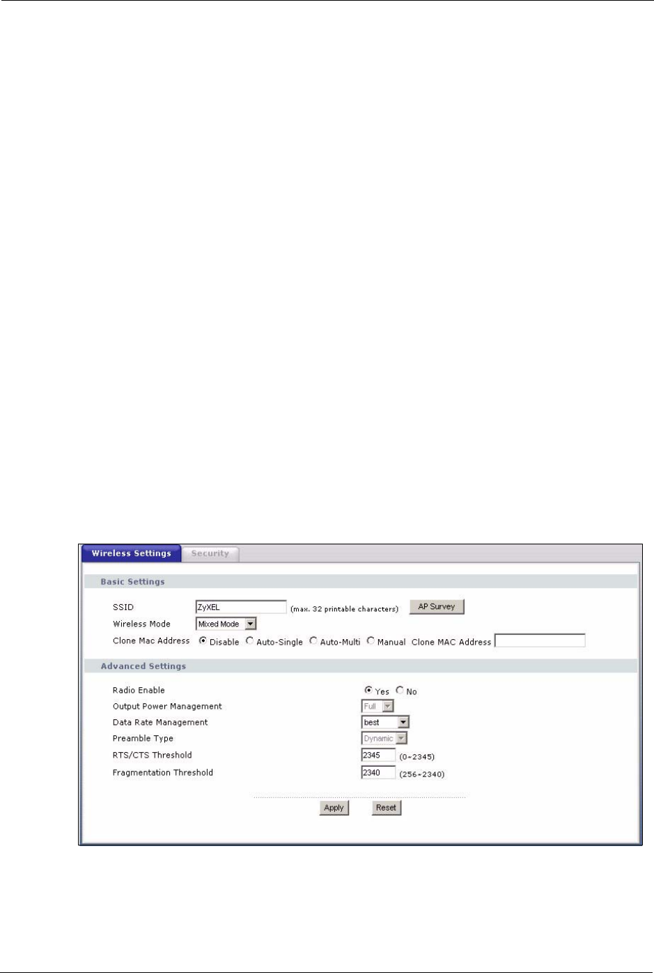
6.3 Configuring Wireless
Click Wireless to display the Wireless Settings screen.
Figure 29 Wireless: Wireless Settings

G-470 User’s Guide
Chapter 6 Wireless Screens 59
The following table describes the labels in this screen.
Table 7 Wireless: Wireless Settings
LABEL DESCRIPTION
SSID Your ZyXEL Device must have the same SSID as the AP you want to connect to.
Enter a descriptive name (up to 32 printable characters) for the wireless LAN.
Spaces are allowed.
Note: If you are configuring the device from a computer connected
to the wireless LAN and you change the device's SSID,
channel or security settings, you will lose your wireless
connection when you press Apply to confirm. You must then
change the wireless settings of your computer to match the
device's new settings.
AP Survey Click this button to open the AP Survey window and select an access point.
Wireless Mode Select Mixed Mode to set the ZyXEL Device to operate in a wireless network with
both 802.11b and 802.11g wireless devices.
Select Pure B Mode to set the ZyXEL Device to operate in a wireless network with
only 802.11b wireless devices. If you select this, the ZyXEL Device may not
communicate with IEEE802.11g wireless devices
Select Pure G Mode to set the ZyXEL Device to operate in a wireless network with
only 802.11g wireless devices. If you select this, the ZyXEL Device may not
communicate with IEEE802.11b wireless devices
Clone MAC
Address
Every Ethernet-capable device is issued with a unique Media Access Control
(MAC) address at the factory. This address is used to identify the device across a
network.
Your ZyXEL Device is capable of “cloning”, or emulating, the MAC addresses of
one or more other devices.
Select Auto-Single to have the ZyXEL Device automatically use the MAC address
of a single Ethernet device connected to the ETHERNET port.
Select Auto-Multi to have the ZyXEL Device automatically use the MAC
addresses of multiple Ethernet devices connected to the ETHERNET port via a
hub.
Alternatively, enter a MAC address into the Clone MAC address field and select
Manual to have the ZyXEL Device use that address.
Advanced Settings
Radio Enable Select Yes to allow wireless communications between the device and other IEEE
802.11b and IEEE 802.11g compliant wireless devices. Select No to stop wireless
communications between the device and other IEEE 802.11b and IEEE 802.11g
compliant wireless devices.
Output Power
Management
Set the output power of the device in this field. If there is a high density of APs
within an area, decrease the output power of the device to reduce interference with
other wireless LAN devices.
Data Rate
Management
Use this field to select a maximum data rate for the wireless connection.
G-470 User’s Guide
60 Chapter 6 Wireless Screens
6.3.1 The AP Survey Window
Click on Wireless > Wireless Settings > AP Survey to display the AP Survey screen. The
ZyXEL Device searches for available access points (APs).
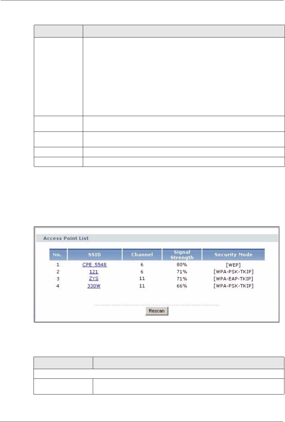
Figure 30 Wireless: the AP Survey Screen
The following table describes the labels in this screen.
Preamble Type Preamble is used to signal that data is coming to the receiver. Select the preamble
type that the AP uses. Short and Long refer to the length of the
synchronization field in a packet.
Short Preamble increases performance as less time sending preamble means
more time for sending data. All IEEE 802.11b/g compliant wireless adapters
support Long Preamble, but not all support short preamble.
Select Auto to have the ZyXEL Device automatically use short preamble when all
access point or wireless stations support it; otherwise the ZyXEL Device uses long
preamble.
Note: The ZyXEL Device and the access point MUST use the same
preamble mode in order to communicate.
RTS/CTS
Threshold
Enter a value between 0 and 2345. The default is 2345.
Fragmentation
Threshold
Enter a value between 256 and 2340. The default is 2340. It is the maximum data
fragment size that can be sent.
Apply Click Apply to save your changes back to the device.
Reset Click Reset to begin configuring this screen afresh.
Table 7 Wireless: Wireless Settings (continued)
LABEL DESCRIPTION
Table 8 Wireless: the AP Survey Screen
LABEL DESCRIPTION
Access Point List
No. This field displays the number of the access point. The access points are
ranked by signal strength.
G-470 User’s Guide
Chapter 6 Wireless Screens 61
6.4 Wireless Security Overview
Wireless security is vital to your network to protect wireless communication between wireless
stations, access points and the wired network.
The figure below shows the possible wireless security levels on your ZyXEL Device. EAP
(Extensible Authentication Protocol) is used for authentication and utilizes dynamic WEP key
exchange. It requires interaction with a RADIUS (Remote Authentication Dial-In User
Service) server either on the WAN or your LAN to provide authentication service for wireless
stations.
If you do not enable any wireless security on your ZyXEL Device, your network is accessible
to any wireless networking device that is within range.
6.5 Configuring Wireless Security
In order to configure and enable wireless security; click Wireless > Security to display the
Security screen. This screen varies according to the encryption method you select.
SSID This field displays the SSID (Service Set IDentifier) of each access point. Click
on an SSID to select that wireless device.
Channel This field displays the channel number used by each access point.
Signal Strength This field displays the signal strength of each access point.
Security Mode This field displays details of the access point’s security and data encryption
settings.
Rescan Click Rescan to have the ZyXEL Device search again for available access
points.
Table 8 Wireless: the AP Survey Screen
LABEL DESCRIPTION
Table 9 Wireless Security Levels
SECURITY LEVEL SECURITY TYPE
L e a s t S e c u r e
Most Secure
Unique SSID (Default)
Unique SSID with Hide SSID Enabled
MAC Address Filtering
WEP Encryption
IEEE802.1x EAP with RADIUS Server Authentication
Wi-Fi Protected Access (WPA)
WPA2
G-470 User’s Guide
62 Chapter 6 Wireless Screens
6.5.1 Wireless Security: Disable
If you do not enable any wireless security on your device, your network is accessible to any
wireless networking device that is within range.
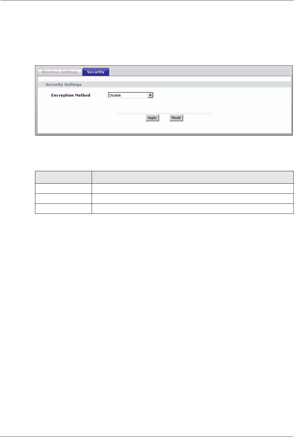
Figure 31 Wireless Security: Disable
The following table describes the labels in this screen.
6.5.2 Wireless Security: WEP
WEP provides a mechanism for encrypting data using encryption keys. Both the AP and the
wireless stations must use the same WEP key to encrypt and decrypt data. You can configure
up to four 64-bit or 128-bit WEP keys, but only one key can be used at any one time.
Table 10 Wireless Security: Disable
LABEL DESCRIPTION
Encryption Method Select Disable to have no wireless LAN security configured.
Apply Click Apply to save your changes back to the device.
Reset Click Reset to begin configuring this screen afresh.
G-470 User’s Guide
Chapter 6 Wireless Screens 63
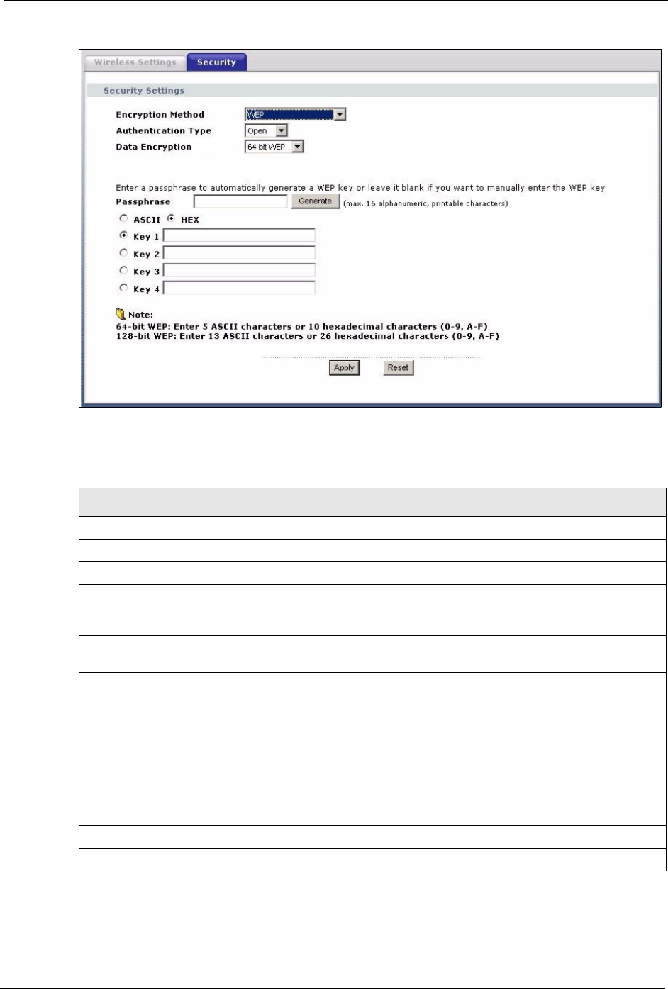
Figure 32 Wireless Security: WEP
The following table describes the labels in this screen.
Table 11 Wireless Security: WEP
LABEL DESCRIPTION
Encryption Method Select WEP if you want to configure WEP encryption parameters.
Authentication Type Select Open or Shared from the drop-down list box.
Data Encryption Select 64 bit WEP or 128 bit WEP to enable data encryption.
Passphrase With 64-bit or 128-bit WEP, you can enter a “passphrase” (password phrase) of
up to 32 case-sensitive printable characters and click Generate to have the
device create four different WEP keys.
Generate After you enter the passphrase, click Generate to have the device generate
four different WEP keys automatically.
Key 1 to Key 4 If you want to manually set the WEP keys, enter the WEP key in the field
provided.
Select a WEP key to use for data encryption.
The WEP keys are used to encrypt data. Both the device and the wireless
stations must use the same WEP key for data transmission.
If you chose 64 bit WEP, then enter any 5 ASCII characters or 10 hexadecimal
characters ("0-9", "A-F").
If you chose 128 bit WEP, then enter 13 ASCII characters or 26 hexadecimal
characters ("0-9", "A-F").
Apply Click Apply to save your changes back to the device.
Reset Click Reset to begin configuring this screen afresh.
G-470 User’s Guide
64 Chapter 6 Wireless Screens
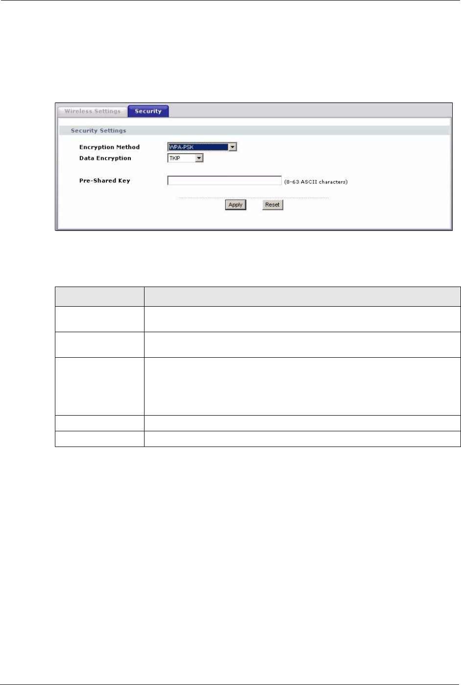
6.5.3 Wireless Security: WPA(2)-PSK
Select WPA-PSK, WPA2-PSK or WPA-PSK & WPA2-PSK in the Encryption Method
drop down list-box to display the next screen.
Figure 33 Wireless Security: WPA(2)-PSK
The following table describes the labels in this screen.
6.5.4 Wireless Security: WPA(2)
WPA (Wi-Fi Protected Access) is a subset of the IEEE 802.11i standard. WPA2 (IEEE
802.11i) is a wireless security standard that defines stronger encryption, authentication and
key management than WPA. Key differences between WPA(2) and WEP are user
authentication and improved data encryption.
Table 12 Wireless Security: WPA-PSK
LABEL DESCRIPTION
Encryption Method Select WPA-PSK, WPA2-PSK or WPA-PSK & WPA2-PSK if you want to
configure a pre-shared key. Choose this option only if your AP supports it.
Data Encryption Select TKIP, AES or TKIP + AES to enable data encryption. For more
information, see the Wireless Security appendix.
Pre-Shared Key The encryption mechanisms used for WPA and WPA-PSK are the same. The
only difference between the two is that WPA-PSK uses a simple common
password, instead of user-specific credentials.
Type a pre-shared key from 8 to 63 ASCII characters (including spaces and
symbols). This field is case-sensitive.
Apply Click Apply to save your changes to the device.
Reset Click Reset to begin configuring this screen afresh.
G-470 User’s Guide
Chapter 6 Wireless Screens 65
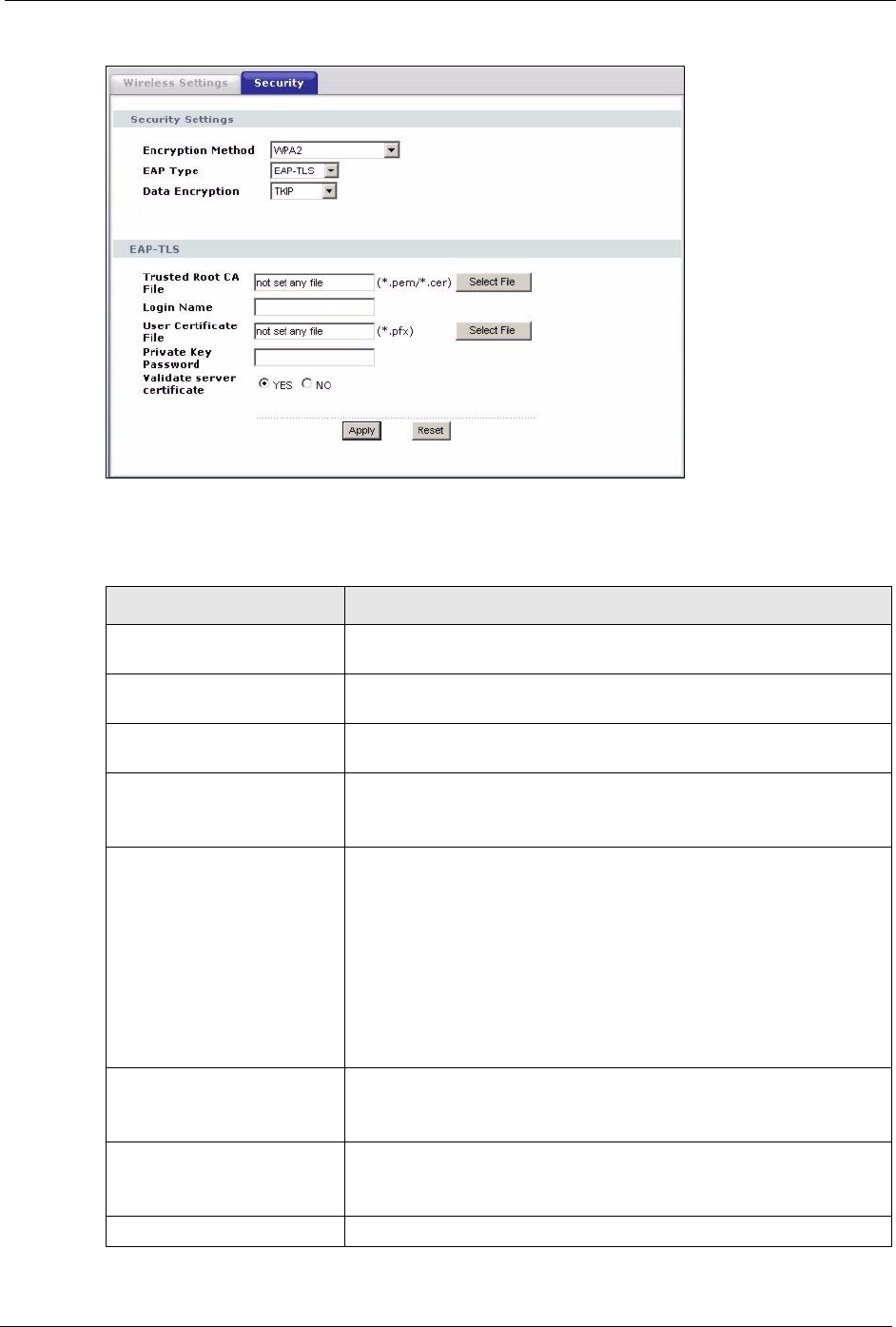
Figure 34 Wireless Security: WPA(2)
The following table describes the labels in this screen.
Table 13 Wireless Security: WPA(2)
LABEL DESCRIPTION
Encryption Method Select WPA, WPA2 or WPA & WPA2 to configure user authentication
and improved data encryption.
EAP Type Select EAP-TLS, EAP-TTLS, EAP-LEAP or EAP-PEAP from the drop-
down box. See the Wireless Security appendix for more information.
Data Encryption Select TKIP, AES or TKIP + AES to enable data encryption. For more
information, see the Wireless Security appendix.
Trusted Root CA File
(EAP-TLS, EAP-TTLS and
EAP-PEAP only)
This is the name of the certificate issued by the certificate authority
(CA).
Select File Click here to choose a certificate.
Select a certificate from the list box and click Select to activate it. Click
Delete if you want to remove a certificate from the list.
Alternatively, click Browse to locate a certificate. Click Upload to add it
to the list.
The certificate file must have a .pem or .cer ending.
Note: You must first have a wired connection to a network
and obtain the certificate(s) from a certificate
authority (CA).
Login Name Enter a user name.
This is the user name that you or an administrator set up on a RADIUS
server.
Password
(EAP-TTLS, EAL-LEAP and
EAP-PEAP only)
Enter the password associated with the login name above.
User Certificate File This is your encrypted private key file.

G-470 User’s Guide
66 Chapter 6 Wireless Screens
6.5.5 Wireless Security: IEEE 802.1x
The IEEE 802.1x standard outlines enhanced security methods for both the authentication of
wireless stations and encryption key management.
Note: Once you enable user authentication, you need to specify an external RADIUS
server on the device for authentication.
Select File Click here to choose a private key.
Select a private key from the list box and click Select to activate it.
Click Delete if you want to remove a private key from the list.
Alternatively, click Browse to locate a private key. Click Upload to add
it to the list.
The private key file must have a .pfx ending.
Private Key Password
(EAP-TLS only)
Enter the password associated with the private key above.
Validate Server Certificate
(EAP-TLS, EAP-TTLS and
EAP-PEAP only)
Select the check box to verify the certificate of the authentication
server.
Apply Click Apply to save your changes to the device.
Reset Click Reset to begin configuring this screen afresh.
Table 13 Wireless Security: WPA(2) (continued)
LABEL DESCRIPTION
G-470 User’s Guide
Chapter 6 Wireless Screens 67
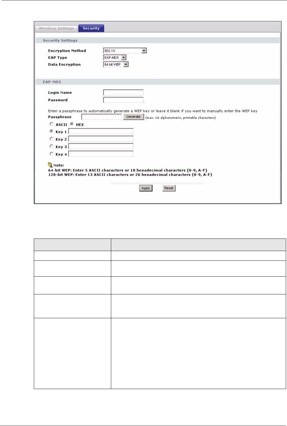
Figure 35 Wireless Security: 802.1x
The following table describes the labels in this screen.
Table 14 Wireless Security: 802.1x
LABEL DESCRIPTION
Encryption Method Select 802.1X to configure encryption key management.
EAP Type Select EAP-TLS, EAP-TTLS, EAP-LEAP or EAP-PEAP from the drop-
down box. See the Wireless Security appendix for more information.
Data Encryption
(EAP-MD5 only)
Select 64 bit WEP or 128 bit WEP to enable data encryption.
Trusted Root CA File
(EAP-TLS, EAP-TTLS and
EAP-PEAP only)
This is the name of the certificate issued by the certificate authority
(CA).
Select File
(EAP-TLS, EAP-TTLS and
EAP-PEAP only)
Click here to choose a certificate.
Select a certificate from the list box and click Select to activate it. Click
Delete if you want to remove a certificate from the list.
Alternatively, click Browse to locate a certificate. Click Upload to add it
to the list.
The certificate file must have a .pem or .cer ending.
Note: You must first have a wired connection to a network
and obtain the certificate(s) from a certificate
authority (CA).

G-470 User’s Guide
68 Chapter 6 Wireless Screens
Login Name Enter a user name.
This is the user name that you or an administrator set up on a RADIUS
server.
Password
(EAP-TTLS, EAL-LEAP and
EAP-PEAP only)
Enter the password associated with the login name above.
User Certificate File
(EAP-TLS only)
This is your encrypted private key file.
Select File
(EAP-TLS only)
Click here to choose a private key.
Select a private key from the list box and click Select to activate it.
Click Delete if you want to remove a private key from the list.
Alternatively, click Browse to locate a private key. Click Upload to add
it to the list.
The private key file must have a .pfx ending.
Private Key Password
(EAP-TLS only)
Enter the password associated with the private key above.
Validate Server Certificate
(EAP-TLS, EAP-TTLS and
EAP-PEAP only)
Select the check box to verify the certificate of the authentication
server.
Passphrase
(EAP-MD5 only)
With 64-bit or 128-bit WEP, you can enter a “passphrase” (password
phrase) of up to 32 case-sensitive printable characters and click
Generate to have the device create four different WEP keys.
Generate
(EAP-MD5 only)
After you enter the passphrase, click Generate to have the device
generate four different WEP keys automatically.
Key 1 to Key 4
(EAP-MD5 only)
If you want to manually set the WEP keys, enter the WEP key in the
field provided.
Select a WEP key to use for data encryption.
The WEP keys are used to encrypt data. Both the device and the
wireless stations must use the same WEP key for data transmission.
If you chose 64 bit WEP, then enter any 5 ASCII characters or 10
hexadecimal characters ("0-9", "A-F").
If you chose 128 bit WEP, then enter 13 ASCII characters or 26
hexadecimal characters ("0-9", "A-F").
Apply Click Apply to save your changes to the device.
Reset Click Reset to begin configuring this screen afresh.
Table 14 Wireless Security: 802.1x
LABEL DESCRIPTION
G-470 User’s Guide
Chapter 7 Management Screens 69
CHAPTER 7
Management Screens
This chapter describes the Management screens.
7.1 Management Overview
Use these management screens to change the password, back up or restore the configuration
files and upgrade your ZyXEL Device’s firmware.
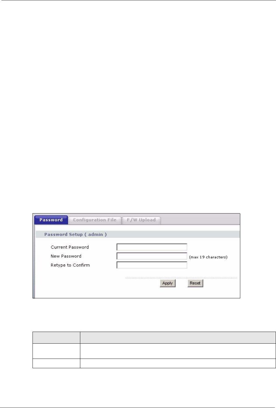
7.2 Password
To change your device's password (recommended), click Management. The screen appears as
shown. This screen allows you to change the device's password.
If you forget your password (or the device IP address), you will need to reset the device. See
Section 4.3 on page 41 for details.
Figure 36 Management: Password
The following table describes the labels in this screen.
Table 15 Management: Password
LABEL DESCRIPTION
Password Setup
(admin)
Use this section to change the password details for the admin username.
Current Password Type in your existing system password (1234 is the default password).
G-470 User’s Guide
70 Chapter 7 Management Screens
7.3 Configuration File
The configuration file (often called the romfile or rom-0) contains the factory default settings
such as password and TCP/IP Setup, etc. It arrives from ZyXEL with a .rom filename
extension. Once you have customized the device's settings, they can be saved back to your
computer under a filename of your choosing.
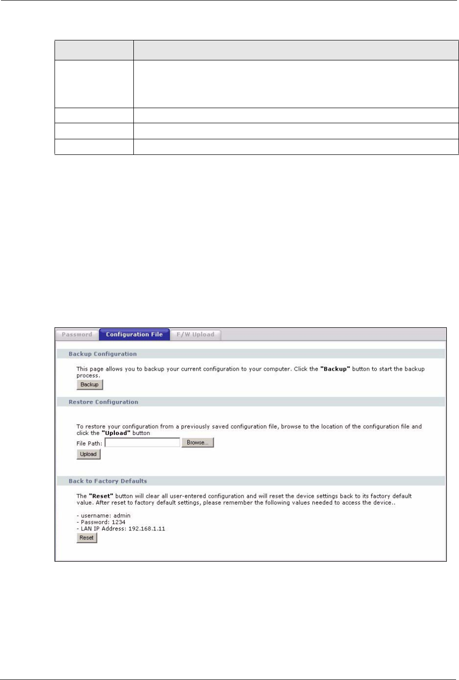
Click Management > Configuration File. Information related to factory defaults, backup
configuration, and restoring configuration appears as shown next.
Figure 37 Management: Configuration File
New Password Type your new system password (up to 19 printable characters). Spaces are not
allowed.
As you type a password, the screen displays an asterisk (*) for each character you
type.
Retype to Confirm Retype your new system password for confirmation.
Apply Save your changes back to the device.
Reset Reload the previous configuration for this screen.
Table 15 Management: Password (continued)
LABEL DESCRIPTION
G-470 User’s Guide
Chapter 7 Management Screens 71
7.3.1 Backup Configuration
Backup configuration allows you to back up (save) the device's current configuration to a file
on your computer. Once your device is configured and functioning properly, it is strongly
recommended that you back up your configuration file before making configuration changes.
The backup configuration file will be useful in case you need to return to your previous
settings.
Click Backup to save the device's current configuration to your computer.
7.3.2 Restore Configuration
Restore configuration allows you to upload a new or previously saved configuration file from
your computer to your device.
Warning: Do not turn off the device while configuration file upload is in progress.
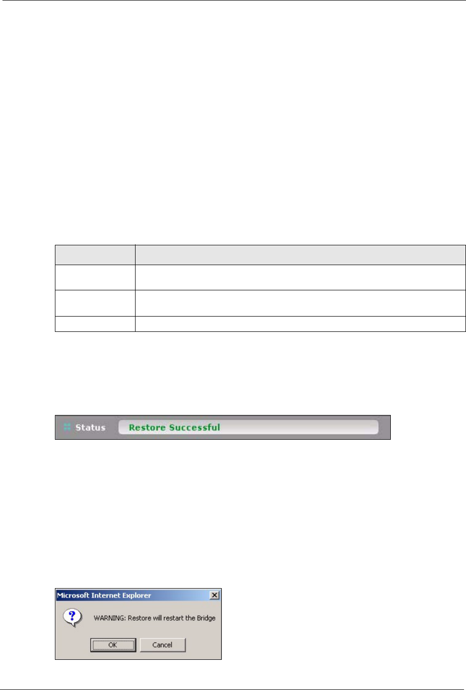
The following screen displays in the Status bar at the bottom of the configurator screen.
Figure 38 Management: Configuration Upload Successful
If you uploaded the default configuration file you may need to change the IP address of your
computer to be in the same subnet as that of the default device IP address (192.168.1.12 to
1.192.168.1.254).
7.3.3 Back to Factory Defaults
Clicking the RESET button in this section clears all user-entered configuration information
and returns the device to its factory defaults. The following warning screen will appear.
Figure 39 Management: Reset Warning Message
Table 16 Management: Configuration File: Restore Configuration
LABEL DESCRIPTION
File Path Type in the location of the file you want to upload in this field or click Browse ... to
find it.
Browse... Click Browse... to find the file you want to upload. Remember that you must
decompress compressed (.zip) files before you can upload them.
Upload Click Upload to begin the upload process.
G-470 User’s Guide
72 Chapter 7 Management Screens
You can also press the RESET button on the rear panel to reset the factory defaults of your
device. Refer to Section 4.6.1 on page 49 for more information on the RESET button.
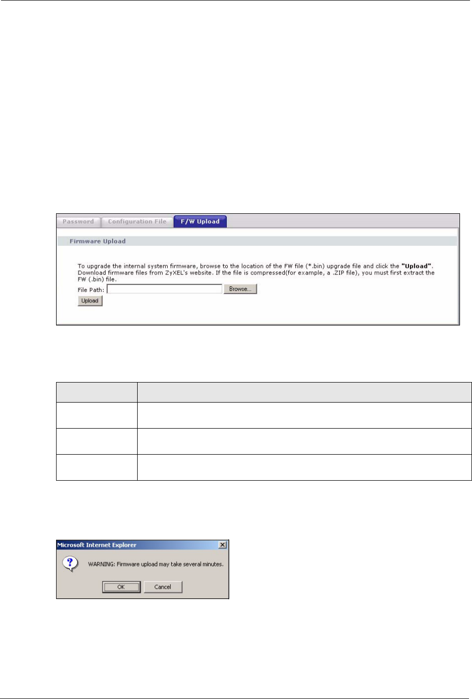
7.4 F/W Upload Screen
Find firmware at www.zyxel.com in a file that (usually) uses the system model name with a
.rmt extension, for example, "zyxel.rmt". The upload process uses HTTP (Hypertext Transfer
Protocol) and may take up to two minutes. After a successful upload, the system will reboot.
Click Management > F/W Upload to display the screen as shown. Follow the instructions in
this screen to upload firmware to your device.
Figure 40 Management: F/W Upload
The following table describes the labels in this screen.
Warning: Do not turn off the device while firmware upload is in progress!
The following screen appears. Click OK to countinue.
Wait until the countdown reaches zero before logging into the device again.
Table 17 Management: F/W Upload
LABEL DESCRIPTION
File Path Type in the location of the file you want to upload in this field or click Browse ... to
find it.
Browse... Click Browse... to find the .rmt file you want to upload. Remember that you must
decompress compressed (.zip) files before you can upload them.
Upload Click Upload to begin the upload process. This process may take up to two
minutes.
G-470 User’s Guide
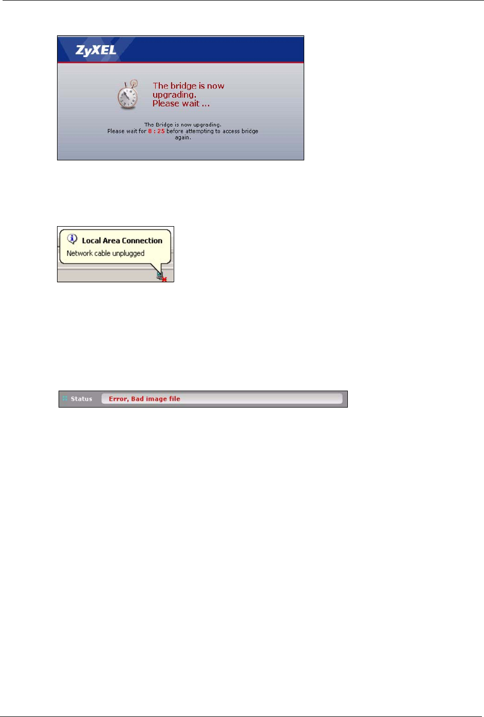
Chapter 7 Management Screens 73
Figure 41 Management: Firmware Upgrading Screen
The device automatically restarts in this time causing a temporary network disconnect. In
some operating systems, you may see the following icon on your desktop.
Figure 42 Network Temporarily Disconnected
After two minutes, log in again and check your new firmware version in the System Status
screen.
If the upload was not successful, the following status message displays at the bottom of the
screen.
Figure 43 Management: Firmware Upload Error

G-470 User’s Guide
74 Chapter 7 Management Screens

G-470 User’s Guide
Chapter 8 Troubleshooting 75
CHAPTER 8
Troubleshooting
This chapter covers potential problems and possible remedies. After each problem description,
some instructions are provided to help you to diagnose and to solve the problem.
8.1 Problems Starting Up the ZyXEL Device
8.2 Problems with the Password
Table 18 Troubleshooting the Start-Up of Your ZyXEL Device
PROBLEM CORRECTIVE ACTION
None of the LEDs
turn on when I
plug in the power
adaptor.
Make sure you are using the supplied power adaptor and that it is plugged in to an
appropriate power source. Check that the power source is turned on.
If the problem persists, you may have a hardware problem. In this case, you should
contact your local vendor.
The device
reboots
automatically
sometimes.
The supplied power to the ZyXEL Device is too low. Check that the ZyXEL Device
is receiving enough power.
Make sure the power source is working properly.
Table 19 Troubleshooting the Password
PROBLEM CORRECTIVE ACTION
I cannot access the
ZyXEL Device.
The Password field is case-sensitive. Make sure that you enter the correct
password using the proper casing.
Use the RESET button on the rear panel of the ZyXEL Device to restore the
factory default configuration file (hold this button in for about 10 seconds or
release the button when the PWR LED starts blinking). This will restore all of the
factory defaults including the password.

G-470 User’s Guide
76 Chapter 8 Troubleshooting
8.3 Problem with the Wireless Link Quality
8.4 Problems Communicating With Other Computers
Table 20 Troubleshooting Link Quality
PROBLEM CORRECTIVE ACTION
The link quality
and/or signal
strength is poor all
the time.
Search and connect to another AP with a better link quality using the Site Survey
screen.
Move your computer closer to the AP or the peer computer(s) within the
transmission range.
There may be too much radio interference (for example microwave or another AP
using the same channel) around your wireless network. Lower the output power of
each AP.
Make sure there are not too many wireless stations connected to a wireless
network.
Table 21 Troubleshooting the Ethernet Interface
PROBLEM CORRECTIVE ACTION
The computer with
the ZyXEL Device
installed cannot
communicate with
the other
computer(s).
In Infrastructure Mode
• Make sure that the AP and the associated computers are turned on and
working properly.
• Make sure the ZyXEL Device and the associated AP use the same SSID.
• Change the AP and the associated wireless clients to use another radio
channel if interference is high.
• Make sure that the computer and the AP share the same security option and
key. Verify the settings in the Profile Security Settings screen.
• If you are using WPA(2) or WPA(2)-PSK security, try changing your
encryption type from TKIP to AES or vice versa.

G-470 User’s Guide
Chapter 8 Troubleshooting 77
8.5 Problems with the Ethernet Interface
Table 22 Troubleshooting the Ethernet Interface
PROBLEM CORRECTIVE ACTION
I cannot access the
ZyXEL Device from
the LAN.
If the ETHN LED on the front panel is off, check the Ethernet cable connection
between your ZyXEL Device and the Ethernet device connected to the
ETHERNET port.
Check for faulty Ethernet cables.
Make sure your computer’s Ethernet adapter is installed and working properly.
Check the IP address of the Ethernet device. Verify that the IP address and the
subnet mask of the ZyXEL Device, the Ethernet device and your computer are
on the same subnet.
I cannot ping any
computer on the
LAN.
If the ETHN LED on the front panel is off, check the Ethernet cable connections
between your ZyXEL Device and the Ethernet device.
Check the Ethernet cable connections between the Ethernet device and the
LAN computers.
Check for faulty Ethernet cables.
Make sure the LAN computer’s Ethernet adapter is installed and working
properly.
Verify that the IP address and the subnet mask of the ZyXEL Device, the
Ethernet device and the LAN computers are on the same subnet.
I cannot access the
web configurator.
Your computer’s and the ZyXEL Device’s IP addresses must be on the same
subnet for LAN access.
If you changed the ZyXEL Device’s IP address, then enter the new one as the
URL.
If you don’t know the ZyXEL Device’s IP address, type the device name of your
ZyXEL Device as the URL. ZyXELXXXX is the default where “XXXX” is the last
four digits of the MAC address. The MAC address is on the bottom of the
device).
If you just changed the ZyXEL Device’s IP address, your computer’s cache of
machine names may contain an entry that maps the name of the ZyXEL Device
to its previous IP address.
In Windows, use nbtstat -R at the command prompt to delete all entries in your
computer’s cache of machine names.
Open a new browser window.
See the following section to check that pop-up windows, JavaScripts and Java
permissions are allowed.
You may also need to clear your Internet browser’s cache.
In Internet Explorer, click Tools and then Internet Options to open the Internet
Options screen.
In the General tab, click Delete Files. In the pop-up window, select the Delete
all offline content check box and click OK. Click OK in the Internet Options
screen to close it.
If you disconnect your computer from one device and connect it to another
device that has the same IP address, your computer’s ARP (Address Resolution
Protocol) table may contain an entry that maps the management IP address to
the previous device’s MAC address).
In Windows, use arp -d at the command prompt to delete all entries in your
computer’s ARP table.
Open a new browser window.
G-470 User’s Guide
78 Chapter 8 Troubleshooting
8.5.1 Pop-up Windows, JavaScripts and Java Permissions
In order to use the web configurator you need to allow:
• Web browser pop-up windows from your device.
• JavaScripts (enabled by default).
• Java permissions (enabled by default).
Note: Internet Explorer 6 screens are used here. Screens for other Internet Explorer
versions may vary.
8.5.1.1 Internet Explorer Pop-up Blockers
You may have to disable pop-up blocking to log into your device.
Either disable pop-up blocking (enabled by default in Windows XP SP (Service Pack) 2) or
allow pop-up blocking and create an exception for your device’s IP address.
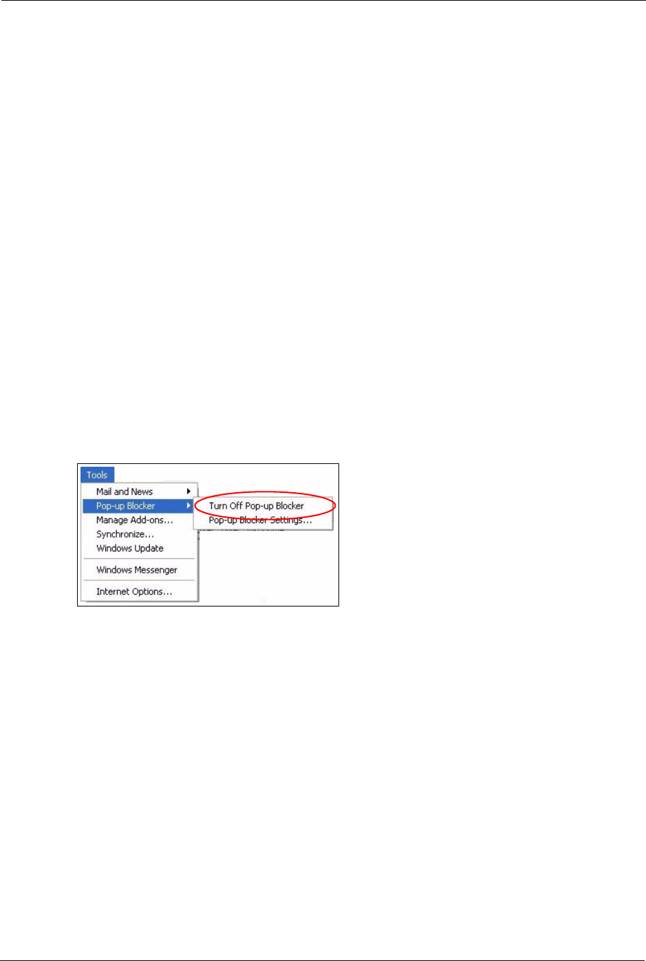
8.5.1.1.1 Disable pop-up Blockers
1In Internet Explorer, select Tools, Pop-up Blocker and then select Turn Off Pop-up
Blocker.
Figure 44 Pop-up Blocker
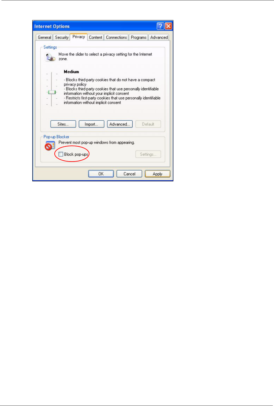
You can also check if pop-up blocking is disabled in the Pop-up Blocker section in the
Privacy tab.
1In Internet Explorer, select Tools, Internet Options, Privacy.
2Clear the Block pop-ups check box in the Pop-up Blocker section of the screen. This
disables any web pop-up blockers you may have enabled.
G-470 User’s Guide
Chapter 8 Troubleshooting 79
Figure 45 Internet Options
3Click Apply to save this setting.
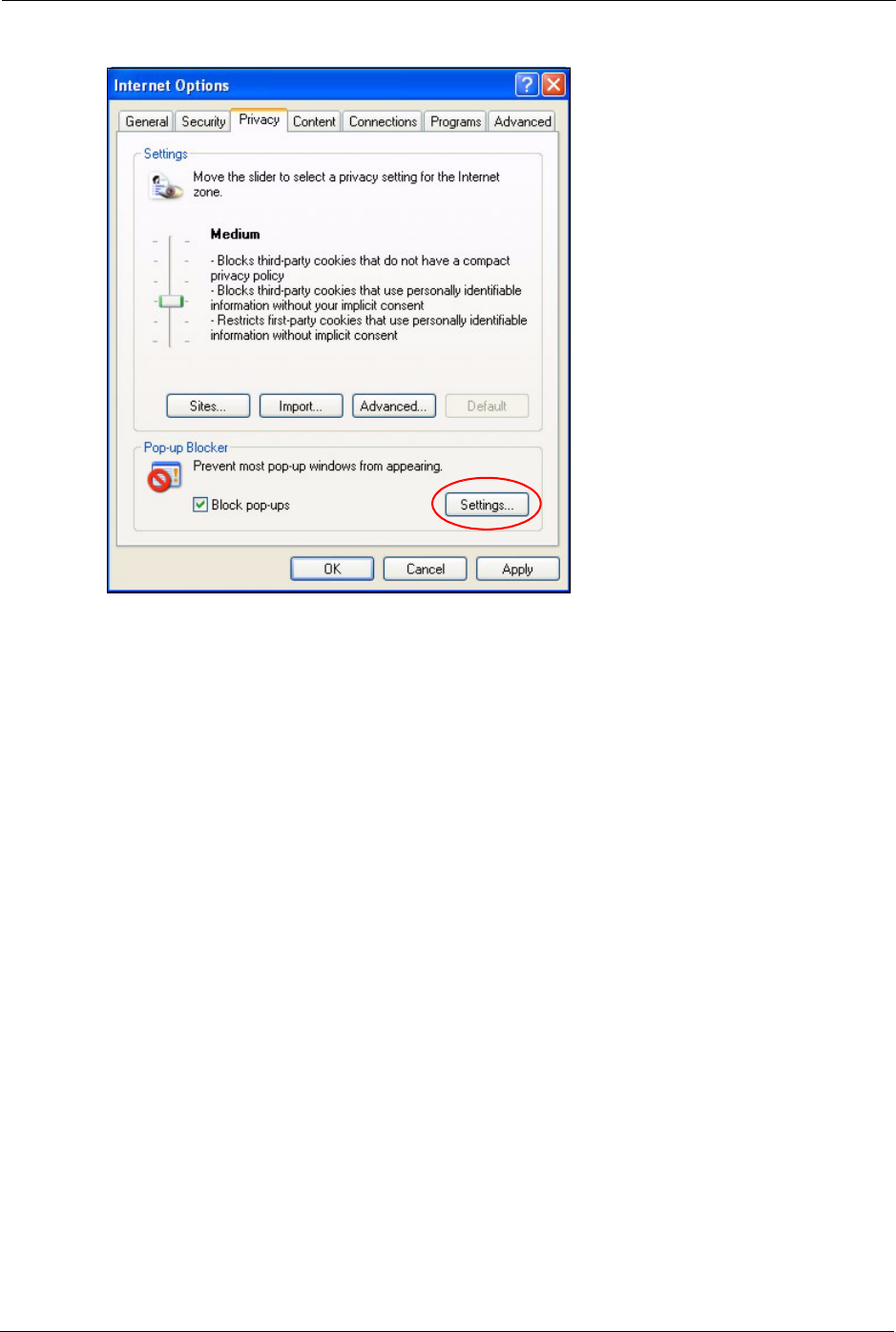
8.5.1.1.2 Enable pop-up Blockers with Exceptions
Alternatively, if you only want to allow pop-up windows from your device, see the following
steps.
1In Internet Explorer, select Tools, Internet Options and then the Privacy tab.
2Select Settings…to open the Pop-up Blocker Settings screen.
G-470 User’s Guide
80 Chapter 8 Troubleshooting
Figure 46 Internet Options: Settings
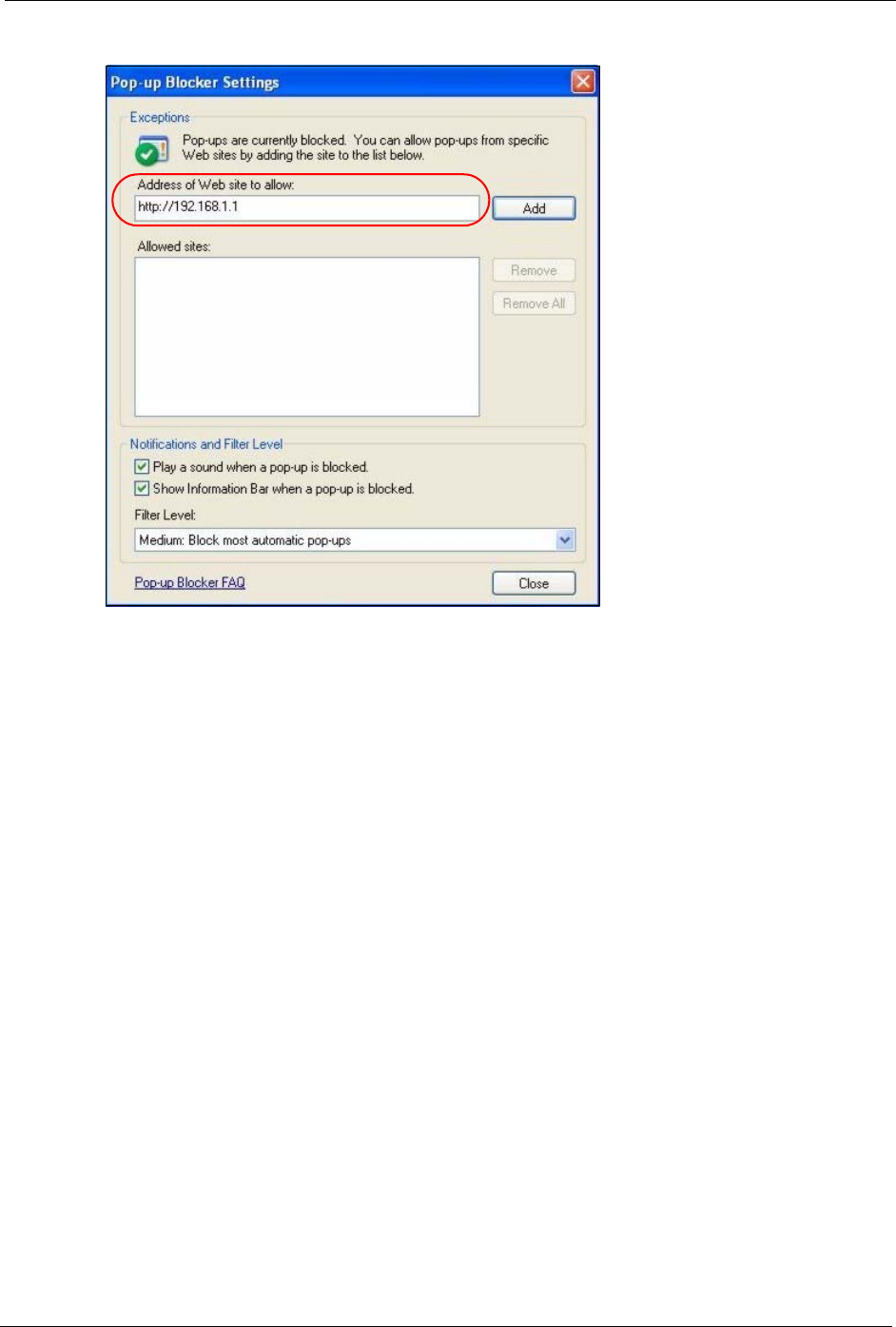
3Type the IP address of your device (the web page that you do not want to have blocked)
with the prefix “http://”. For example, http://192.168.1.11.
4Click Add to move the IP address to the list of Allowed sites.
G-470 User’s Guide
Chapter 8 Troubleshooting 81
Figure 47 Pop-up Blocker Settings
5Click Close to return to the Privacy screen.
6Click Apply to save this setting.
8.5.1.2 JavaScripts
If pages of the web configurator do not display properly in Internet Explorer, check that
JavaScripts are allowed.
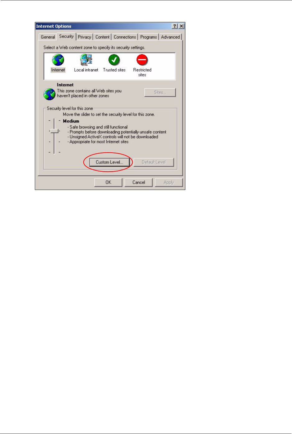
1In Internet Explorer, click Tools, Internet Options and then the Security tab.
G-470 User’s Guide
82 Chapter 8 Troubleshooting
Figure 48 Internet Options: Custom Level
2Click the Custom Level... button.
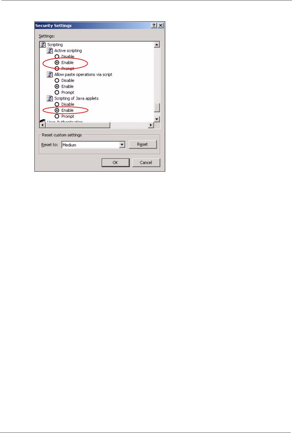
3Scroll down to Scripting.
4Under Active scripting make sure that Enable is selected (the default).
5Under Scripting of Java applets make sure that Enable is selected (the default).
6Click OK to close the window.
G-470 User’s Guide
Chapter 8 Troubleshooting 83
Figure 49 Security Settings - Java Scripting
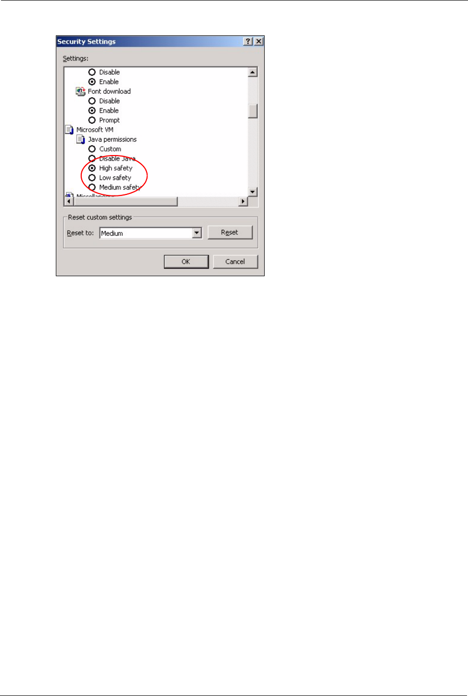
8.5.1.3 Java Permissions
1From Internet Explorer, click Tools, Internet Options and then the Security tab.
2Click the Custom Level... button.
3Scroll down to Microsoft VM.
4Under Java permissions make sure that a safety level is selected.
5Click OK to close the window.
G-470 User’s Guide
84 Chapter 8 Troubleshooting
Figure 50 Security Settings - Java
8.5.1.3.1 JAVA (Sun)
1From Internet Explorer, click Tools, Internet Options and then the Advanced tab.
2make sure that Use Java 2 for <applet> under Java (Sun) is selected.
3Click OK to close the window.

G-470 User’s Guide
Chapter 8 Troubleshooting 85
Figure 51 Java (Sun)
8.6 Testing the Connection to the ZyXEL Device
1Click Start, (All) Programs, Accessories and then Command Prompt.
2In the Command Prompt window, type “ping” followed by a space and the IP address of
the ZyXEL Device (192.168.1.11 is the default).
3Press ENTER. The following screen displays.
Figure 52 Pinging the G-470
Your computer can now communicate with the ZyXEL Device via the ETHERNET port.
C:\>ping 192.168.1.11
Pinging 192.168.1.11 with 32 bytes of data:
Reply from 192.168.1.11: bytes=32 time=10ms TTL=254
Reply from 192.168.1.11: bytes=32 time<10ms TTL=254
Reply from 192.168.1.11: bytes=32 time<10ms TTL=254
Reply from 192.168.1.11: bytes=32 time<10ms TTL=254
Ping statistics for 192.168.1.11:
Packets: Sent = 4, Received = 4, Lost = 0 (0% loss),
Approximate round trip times in milli-seconds:
Minimum = 0ms, Maximum = 10ms, Average = 2m

G-470 User’s Guide
86 Chapter 8 Troubleshooting

G-470 User’s Guide
Appendix A 87
APPENDIX A
Product Specifications
Table 23 Product Specifications
PHYSICAL AND ENVIRONMENTAL
Product Name G-470 802.11g Wireless Ethernet Adapter
Standards IEEE 802.11b
IEEE 802.11g
Network Architectures Infrastructure
Security 64/128-bit WEP Encryption
WPA/WPA-PSK
IEEE 802.1x
Operating Temperature 0 ~ 50 degrees Centigrade
Storage Temperature -25 ~ 70 degrees Centigrade
Operating Humidity 0 ~ 70% (non-condensing)
Storage Humidity 10 ~ 90% (non-condensing)
Power Consumption TX: 620mA RX: 600mA
Voltage 5V
Dimensions 104mm × 127mm × 26mm excluding external antenna and foot
stand.
RADIO SPECIFICATIONS
Media Access Protocol IEEE 802.11
Frequency USA (FCC) & Canada 11 Channels
Europe (ETSI) 13 Channels
Japan (TELEC) 13 Channels
Data Rate IEEE 802.11g: 54, 48, 36, 24, 18, 12, 9, 6 Mbps
IEEE 802.11b: 11, 5.5, 2, 1 Mbps
Modulation IEEE 802.11g: OFDM (64QAM, 16QAM, QPSK, BPSK)
IEEE 802.11b: Direct Sequence Spread Spectrum (DSSS), (CCK,
DQPSK, DBPSK)
Peak Output Power 27.88dBm
Rx Sensitivity IEEE 802.11g At 54Mbps -72dBm (typical)
IEEE 802.11g At 24Mbps -82dBm (typical)
SOFTWARE SPECIFICATIONS
Device Drivers Windows 2000, Windows XP, Windows ME, Windows 98SE,
Windows NT 4.0
Roaming IEEE 802.11b/g compliant
WEP 64/128-bit WEP encryption

G-470 User’s Guide
88 Appendix A

G-470 User’s Guide
Appendix B 89
APPENDIX B
Wireless Security
Types of EAP Authentication
This section discusses some popular authentication types: EAP-MD5, EAP-TLS, EAP-TTLS,
PEAP and LEAP.
The type of authentication you use depends on the RADIUS server or the AP. Consult your
network administrator for more information. Your wireless LAN device may not support all
authentication types.
EAP-MD5 (Message-Digest Algorithm 5)
MD5 authentication is the simplest one-way authentication method. The authentication server
sends a challenge to the wireless station. The wireless station ‘proves’ that it knows the
password by encrypting the password with the challenge and sends back the information.
Password is not sent in plain text.
However, MD5 authentication has some weaknesses. Since the authentication server needs to
get the plaintext passwords, the passwords must be stored. Thus someone other than the
authentication server may access the password file. In addition, it is possible to impersonate an
authentication server as MD5 authentication method does not perform mutual authentication.
Finally, MD5 authentication method does not support data encryption with dynamic session
key. You must configure WEP encryption keys for data encryption.
EAP-TLS (Transport Layer Security)
With EAP-TLS, digital certifications are needed by both the server and the wireless stations
for mutual authentication. The server presents a certificate to the client. After validating the
identity of the server, the client sends a different certificate to the server. The exchange of
certificates is done in the open before a secured tunnel is created. This makes user identity
vulnerable to passive attacks. A digital certificate is an electronic ID card that authenticates the
sender’s identity. However, to implement EAP-TLS, you need a Certificate Authority (CA) to
handle certificates, which imposes a management overhead.

G-470 User’s Guide
90 Appendix B
EAP-TTLS (Tunneled Transport Layer Service)
EAP-TTLS is an extension of the EAP-TLS authentication that uses certificates for only the
server-side authentications to establish a secure connection. Client authentication is then done
by sending username and password through the secure connection, thus client identity is
protected. For client authentication, EAP-TTLS supports EAP methods and legacy
authentication methods such as PAP, CHAP, MS-CHAP and MS-CHAP v2.
PEAP (Protected EAP)
Like EAP-TTLS, server-side certificate authentication is used to establish a secure connection,
then use simple username and password methods through the secured connection to
authenticate the clients, thus hiding client identity. However, PEAP only supports EAP
methods, such as EAP-MD5, EAP-MSCHAPv2 and EAP-GTC (EAP-Generic Token Card),
for client authentication. EAP-GTC is implemented only by Cisco.
LEAP
LEAP (Lightweight Extensible Authentication Protocol) is a Cisco implementation of IEEE
802.1x.
Dynamic WEP Key Exchange
The AP maps a unique key that is generated with the RADIUS server. This key expires when
the wireless connection times out, disconnects or reauthentication times out. A new WEP key
is generated each time reauthentication is performed.
If this feature is enabled, it is not necessary to configure a default encryption key in the
Wireless screen. You may still configure and store keys here, but they will not be used while
Dynamic WEP is enabled.
Note: EAP-MD5 cannot be used with Dynamic WEP Key Exchange
For added security, certificate-based authentications (EAP-TLS, EAP-TTLS and PEAP) use
dynamic keys for data encryption. They are often deployed in corporate environments, but for
public deployment, a simple user name and password pair is more practical. The following
table is a comparison of the features of authentication types.
Table 24 Comparison of EAP Authentication Types
EAP-MD5 EAP-TLS EAP-TTLS PEAP LEAP
Mutual Authentication No Yes Yes Yes Yes
Certificate – Client No Yes Optional Optional No
Certificate – Server No Yes Yes Yes No
Dynamic Key Exchange No Yes Yes Yes Yes
Credential Integrity None Strong Strong Strong Moderate

G-470 User’s Guide
Appendix B 91
WPA(2)
Wi-Fi Protected Access (WPA) is a subset of the IEEE 802.11i standard. WPA2 (IEEE
802.11i) is a wireless security standard that defines stronger encryption, authentication and
key management than WPA.
Key differences between WPA(2) and WEP are improved data encryption and user
authentication.
If both an AP and the wireless clients support WPA2 and you have an external RADIUS
server, use WPA2 for stronger data encryption. If you don't have an external RADIUS server,
you should use WPA2-PSK (WPA2-Pre-Shared Key) that only requires a single (identical)
password entered into each access point, wireless gateway and wireless client. As long as the
passwords match, a wireless client will be granted access to a WLAN.
If the AP or the wireless clients do not support WPA2, just use WPA or WPA-PSK depending
on whether you have an external RADIUS server or not.
Select WEP only when the AP and/or wireless clients do not support WPA or WPA2. WEP is
less secure than WPA or WPA2.
Encryption
Both WPA and WPA2 improve data encryption by using Temporal Key Integrity Protocol
(TKIP), Message Integrity Check (MIC) and IEEE 802.1x. WPA and WPA2 use Advanced
Encryption Standard (AES) in the Counter mode with Cipher block chaining Message
authentication code Protocol (CCMP) to offer stronger encryption than TKIP.
TKIP uses 128-bit keys that are dynamically generated and distributed by the authentication
server. AES (Advanced Encryption Standard) is a block cipher that uses a 256-bit
mathematical algorithm called Rijndael. They both include a per-packet key mixing function,
a Message Integrity Check (MIC) named Michael, an extended initialization vector (IV) with
sequencing rules, and a re-keying mechanism.
WPA and WPA2 regularly change and rotate the encryption keys so that the same encryption
key is never used twice.
The RADIUS server distributes a Pairwise Master Key (PMK) key to the AP that then sets up
a key hierarchy and management system, using the PMK to dynamically generate unique data
encryption keys to encrypt every data packet that is wirelessly communicated between the AP
and the wireless stations. This all happens in the background automatically.
Deployment Difficulty Easy Hard Moderate Moderate Moderate
Client Identity Protection No No Yes Yes No
Table 24 Comparison of EAP Authentication Types
EAP-MD5 EAP-TLS EAP-TTLS PEAP LEAP

G-470 User’s Guide
92 Appendix B
The Message Integrity Check (MIC) is designed to prevent an attacker from capturing data
packets, altering them and resending them. The MIC provides a strong mathematical function
in which the receiver and the transmitter each compute and then compare the MIC. If they do
not match, it is assumed that the data has been tampered with and the packet is dropped.
By generating unique data encryption keys for every data packet and by creating an integrity
checking mechanism (MIC), with TKIP and AES it is more difficult to decrypt data on a Wi-Fi
network than WEP and difficult for an intruder to break into the network.
The encryption mechanisms used for WPA(2) and WPA(2)-PSK are the same. The only
difference between the two is that WPA(2)-PSK uses a simple common password, instead of
user-specific credentials. The common-password approach makes WPA(2)-PSK susceptible to
brute-force password-guessing attacks but it’s still an improvement over WEP as it employs a
consistent, single, alphanumeric password to derive a PMK which is used to generate unique
temporal encryption keys. This prevent all wireless devices sharing the same encryption keys.
(a weakness of WEP)
User Authentication
WPA and WPA2 apply IEEE 802.1x and Extensible Authentication Protocol (EAP) to
authenticate wireless stations using an external RADIUS database. WPA2 reduces the number
of key exchange messages from six to four (CCMP 4-way handshake) and shortens the time
required to connect to a network. Other WPA2 authentication features that are different from
WPA include key caching and pre-authentication. These two features are optional and may not
be supported in all wireless devices.
Key caching allows a wireless client to store the PMK it derived through a successful
authentication with an AP. The wireless client uses the PMK when it tries to connect to the
same AP and does not need to go with the authentication process again.
Pre-authentication enables fast roaming by allowing the wireless client (already connecting to
an AP) to perform IEEE 802.1x authentication with another AP before connecting to it.
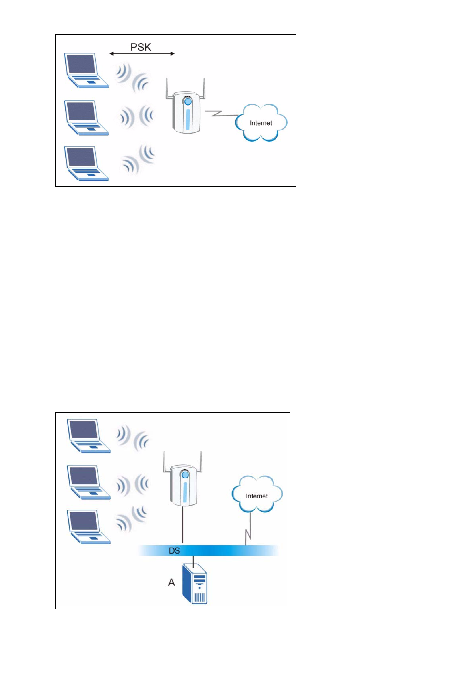
WPA(2)-PSK Application Example
A WPA(2)s-PSK application looks as follows.
1First enter identical passwords into the AP and all wireless clients. The Pre-Shared Key
(PSK) must consist of between 8 and 63 ASCII characters or 64 hexadecimal characters
(including spaces and symbols).
2The AP checks each client's password and (only) allows it to join the network if it
matches its password.
3The AP and wireless clients use the pre-shared key to generate a common PMK.
4The AP and wireless clients use the TKIP or AES encryption process to encrypt data
exchanged between them.
G-470 User’s Guide
Appendix B 93
Figure 53 WPA-PSK Authentication
WPA(2) with RADIUS Application Example
You need the IP address of the RADIUS server, its port number (default is 1812), and the
RADIUS shared secret. A WPA(2) application example with an external RADIUS server
looks as follows. "A" is the RADIUS server. "DS" is the distribution system.
1The AP passes the wireless client's authentication request to the RADIUS server.
2The RADIUS server then checks the user's identification against its database and grants
or denies network access accordingly.
3The RADIUS server distributes a Pairwise Master Key (PMK) key to the AP that then
sets up a key hierarchy and management system, using the pair-wise key to dynamically
generate unique data encryption keys to encrypt every data packet that is wirelessly
communicated between the AP and the wireless clients.
Figure 54 WPA(2) with RADIUS Application Example

G-470 User’s Guide
94 Appendix B
Security Parameters Summary
Refer to this table to see what other security parameters you should configure for each
Authentication Method/ key management protocol type. MAC address filters are not
dependent on how you configure these security features.
Table 25 Wireless Security Relational Matrix
AUTHENTICATION
METHOD/ KEY
MANAGEMENT PROTOCOL
ENCRYPTION
METHOD
ENTER
MANUAL KEY IEEE 802.1X
Open None No Disable
Enable without Dynamic WEP Key
Open WEP No Enable with Dynamic WEP Key
Yes Enable without Dynamic WEP Key
Yes Disable
Shared WEP No Enable with Dynamic WEP Key
Yes Enable without Dynamic WEP Key
Yes Disable
WPA TKIP/AES No Enable
WPA-PSK TKIP/AES Yes Disable
WPA2 TKIP/AES No Enable
WPA2-PSK TKIP/AES Yes Disable

G-470 User’s Guide
Appendix C 95
APPENDIX C
Setting up Your Computer’s IP Address
All computers must have a 10M or 100M Ethernet adapter card and TCP/IP installed.
Windows 95/98/Me/NT/2000/XP, Macintosh OS 7 and later operating systems and all
versions of UNIX/LINUX include the software components you need to install and use TCP/
IP on your computer. Windows 3.1 requires the purchase of a third-party TCP/IP application
package.
TCP/IP should already be installed on computers using Windows NT/2000/XP, Macintosh OS
7 and later operating systems.
After the appropriate TCP/IP components are installed, configure the TCP/IP settings in order
to "communicate" with your network.
Windows 95/98/Me
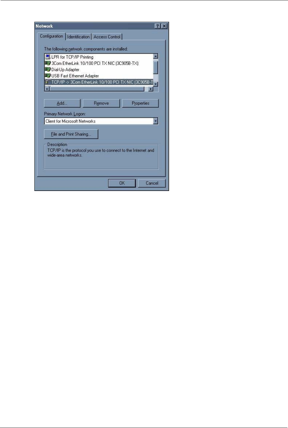
Click Start, Settings, Control Panel and double-click the Network icon to open the Network
window
G-470 User’s Guide
96 Appendix C
Figure 55 WIndows 95/98/Me: Network: Configuration
Installing Components
The Network window Configuration tab displays a list of installed components. You need a
network adapter, the TCP/IP protocol and Client for Microsoft Networks.
If you need the adapter:
1In the Network window, click Add.
2Select Adapter and then click Add.
3Select the manufacturer and model of your network adapter and then click OK.
If you need TCP/IP:
1In the Network window, click Add.
2Select Protocol and then click Add.
3Select Microsoft from the list of manufacturers.
4Select TCP/IP from the list of network protocols and then click OK.
If you need Client for Microsoft Networks:
1Click Add.
2Select Client and then click Add.
G-470 User’s Guide
Appendix C 97
3Select Microsoft from the list of manufacturers.
4Select Client for Microsoft Networks from the list of network clients and then click
OK.
5Restart your computer so the changes you made take effect.
Configuring
1In the Network window Configuration tab, select your network adapter's TCP/IP entry
and click Properties
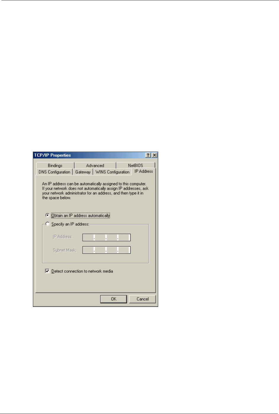
2Click the IP Address tab.
• If your IP address is dynamic, select Obtain an IP address
automatically.
• If you have a static IP address, select Specify an IP address and type
your information into the IP Address and Subnet Mask fields.
Figure 56 Windows 95/98/Me: TCP/IP Properties: IP Address
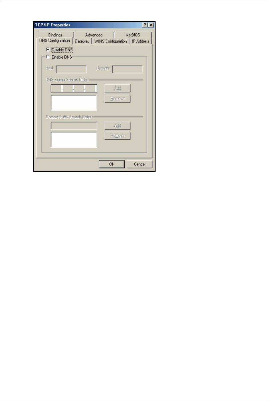
3Click the DNS Configuration tab.
• If you do not know your DNS information, select Disable DNS.
• If you know your DNS information, select Enable DNS and type the
information in the fields below (you may not need to fill them all in).
G-470 User’s Guide
98 Appendix C
Figure 57 Windows 95/98/Me: TCP/IP Properties: DNS Configuration
4Click the Gateway tab.
• If you do not know your gateway’s IP address, remove previously
installed gateways.
• If you have a gateway IP address, type it in the New gateway field
and click Add.
5Click OK to save and close the TCP/IP Properties window.
6Click OK to close the Network window. Insert the Windows CD if prompted.
7Restart your computer when prompted.
Verifying Settings
1Click Start and then Run.
2In the Run window, type "winipcfg" and then click OK to open the IP Configuration
window.
3Select your network adapter. You should see your computer's IP address, subnet mask
and default gateway.
Windows 2000/NT/XP
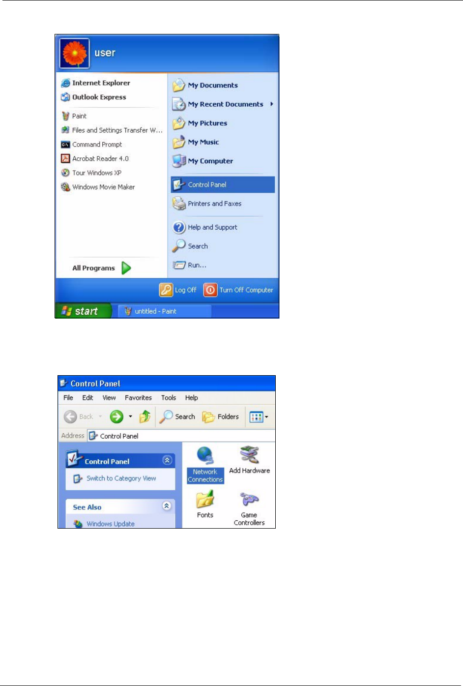
1For Windows XP, click start, Control Panel. In Windows 2000/NT, click Start,
Settings, Control Panel.
G-470 User’s Guide
Appendix C 99
Figure 58 Windows XP: Start Menu
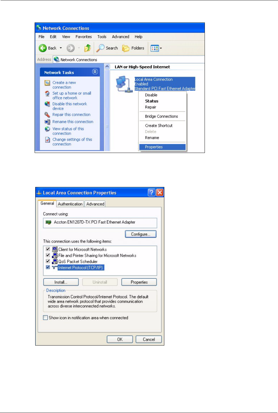
2For Windows XP, click Network Connections. For Windows 2000/NT, click Network
and Dial-up Connections.
Figure 59 Windows XP: Control Panel
3Right-click Local Area Connection and then click Properties.
G-470 User’s Guide
100 Appendix C
Figure 60 Windows XP: Control Panel: Network Connections: Properties
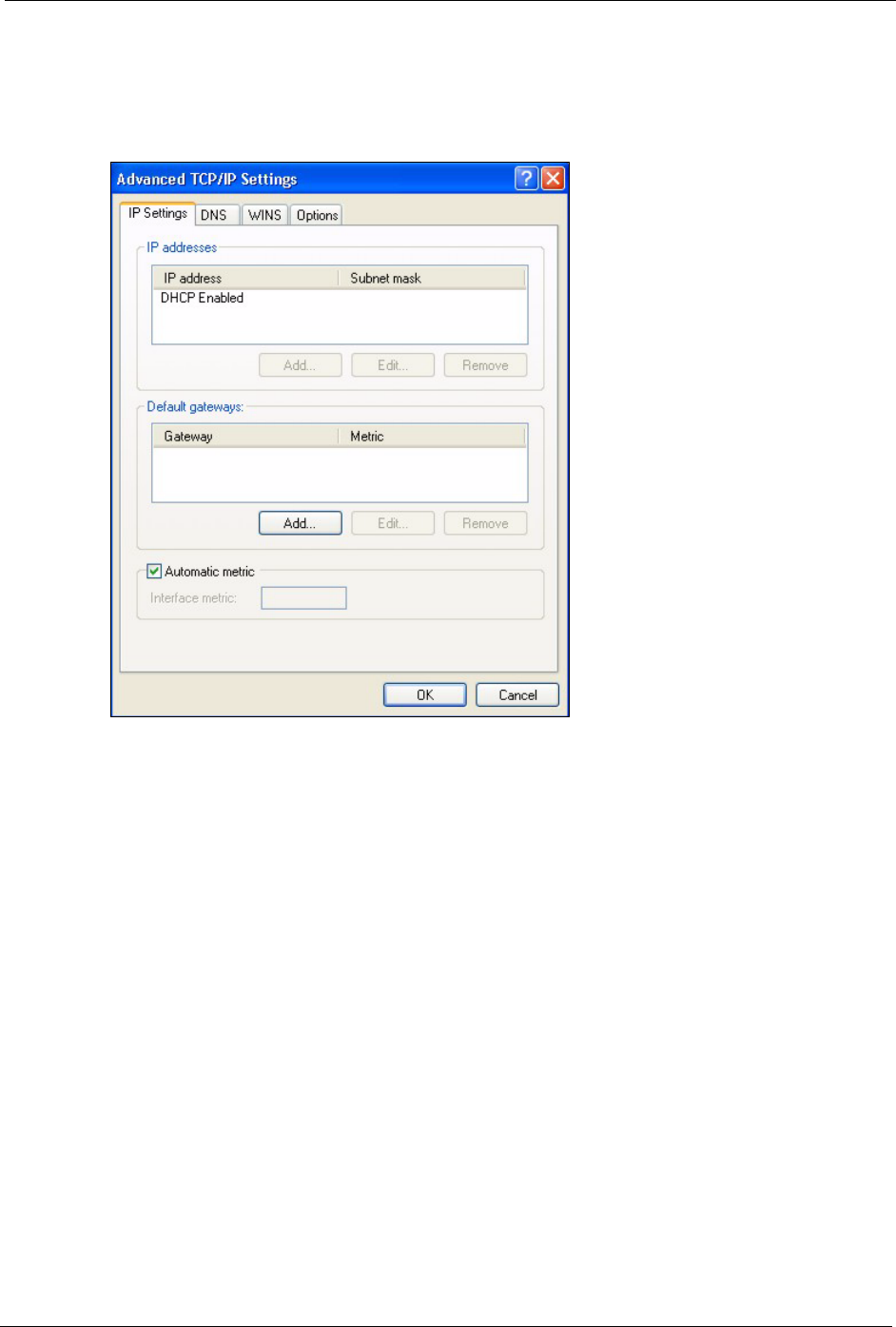
4Select Internet Protocol (TCP/IP) (under the General tab in Win XP) and click
Properties.
Figure 61 Windows XP: Local Area Connection Properties
5The Internet Protocol TCP/IP Properties window opens (the General tab in Windows
XP).
• If you have a dynamic IP address click Obtain an IP address
automatically.
G-470 User’s Guide
Appendix C 101
• If you have a static IP address click Use the following IP Address
and fill in the IP address, Subnet mask, and Default gateway fields.
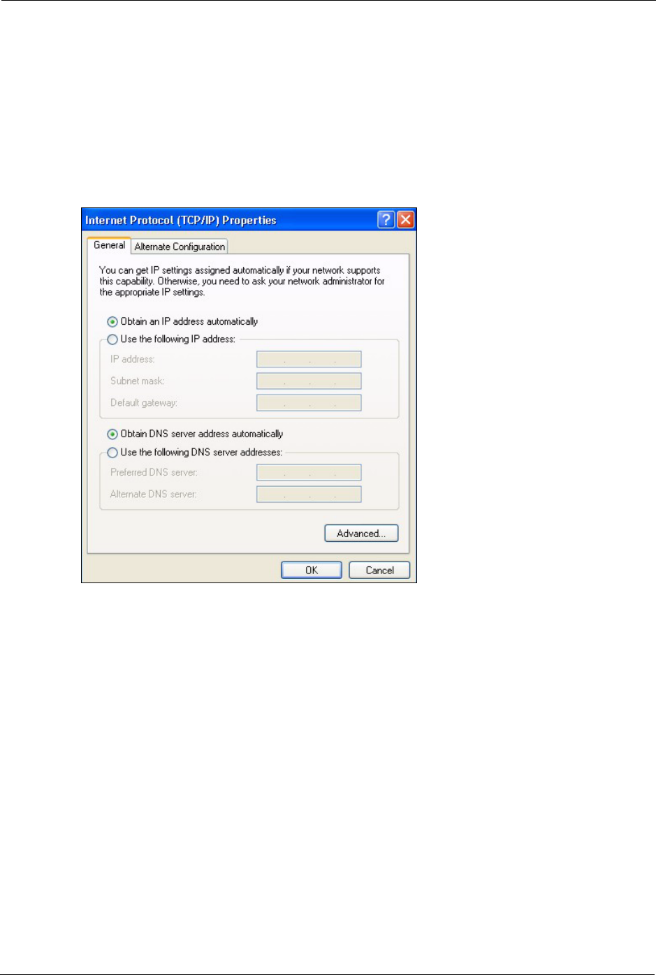
Click Advanced.
Figure 62 Windows XP: Advanced TCP/IP Settings
6If you do not know your gateway's IP address, remove any previously installed gateways
in the IP Settings tab and click OK.
Do one or more of the following if you want to configure additional IP addresses:
•In the IP Settings tab, in IP addresses, click Add.
•In TCP/IP Address, type an IP address in IP address and a subnet
mask in Subnet mask, and then click Add.
• Repeat the above two steps for each IP address you want to add.
• Configure additional default gateways in the IP Settings tab by
clicking Add in Default gateways.
•In TCP/IP Gateway Address, type the IP address of the default
gateway in Gateway. To manually configure a default metric (the
number of transmission hops), clear the Automatic metric check box
and type a metric in Metric.
• Click Add.
• Repeat the previous three steps for each default gateway you want to
add.
• Click OK when finished.
7In the Internet Protocol TCP/IP Properties window (the General tab in Windows XP):
G-470 User’s Guide
102 Appendix C
• Click Obtain DNS server address automatically if you do not know
your DNS server IP address(es).
• If you know your DNS server IP address(es), click Use the following
DNS server addresses, and type them in the Preferred DNS server
and Alternate DNS server fields.
If you have previously configured DNS servers, click Advanced and
then the DNS tab to order them.
Figure 63 Windows XP: Internet Protocol (TCP/IP) Properties
8Click OK to close the Internet Protocol (TCP/IP) Properties window.
9Click OK to close the Local Area Connection Properties window.
10Restart your computer (if prompted).
Verifying Settings
1Click Start, All Programs, Accessories and then Command Prompt.
2In the Command Prompt window, type "ipconfig" and then press [ENTER]. You can
also open Network Connections, right-click a network connection, click Status and then
click the Support tab.
Macintosh OS 8/9
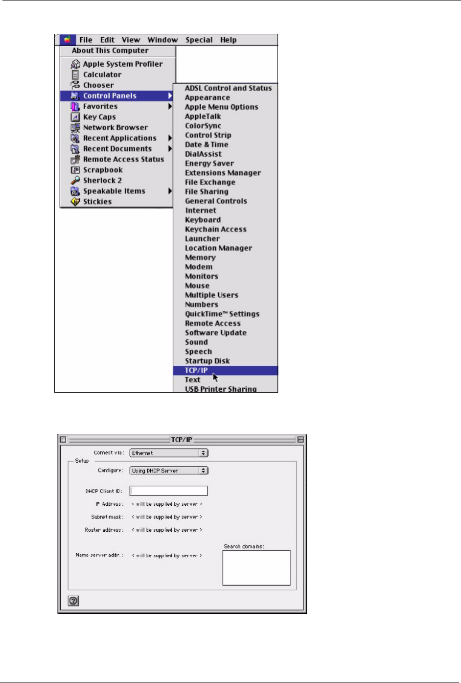
1Click the Apple menu, Control Panel and double-click TCP/IP to open the TCP/IP
Control Panel.
G-470 User’s Guide
Appendix C 103
Figure 64 Macintosh OS 8/9: Apple Menu
2Select Ethernet built-in from the Connect via list.
Figure 65 Macintosh OS 8/9: TCP/IP
3For dynamically assigned settings, select Using DHCP Server from the Configure: list.
4For statically assigned settings, do the following:
G-470 User’s Guide
104 Appendix C
•From the Configure box, select Manually.
• Type your IP address in the IP Address box.
• Type your subnet mask in the Subnet mask box.
• Type the IP address of your gateway in the Router address box if
you have one.
5Close the TCP/IP Control Panel.
6Click Save if prompted, to save changes to your configuration.
7Restart your computer (if prompted).
Verifying Settings
Check your TCP/IP properties in the TCP/IP Control Panel window.
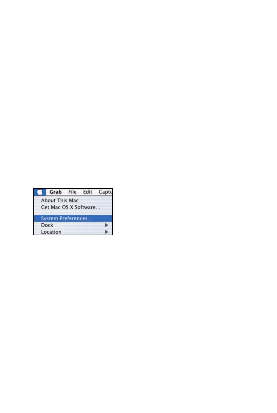
Macintosh OS X
1Click the Apple menu, and click System Preferences to open the System Preferences
window.
Figure 66 Macintosh OS X: Apple Menu
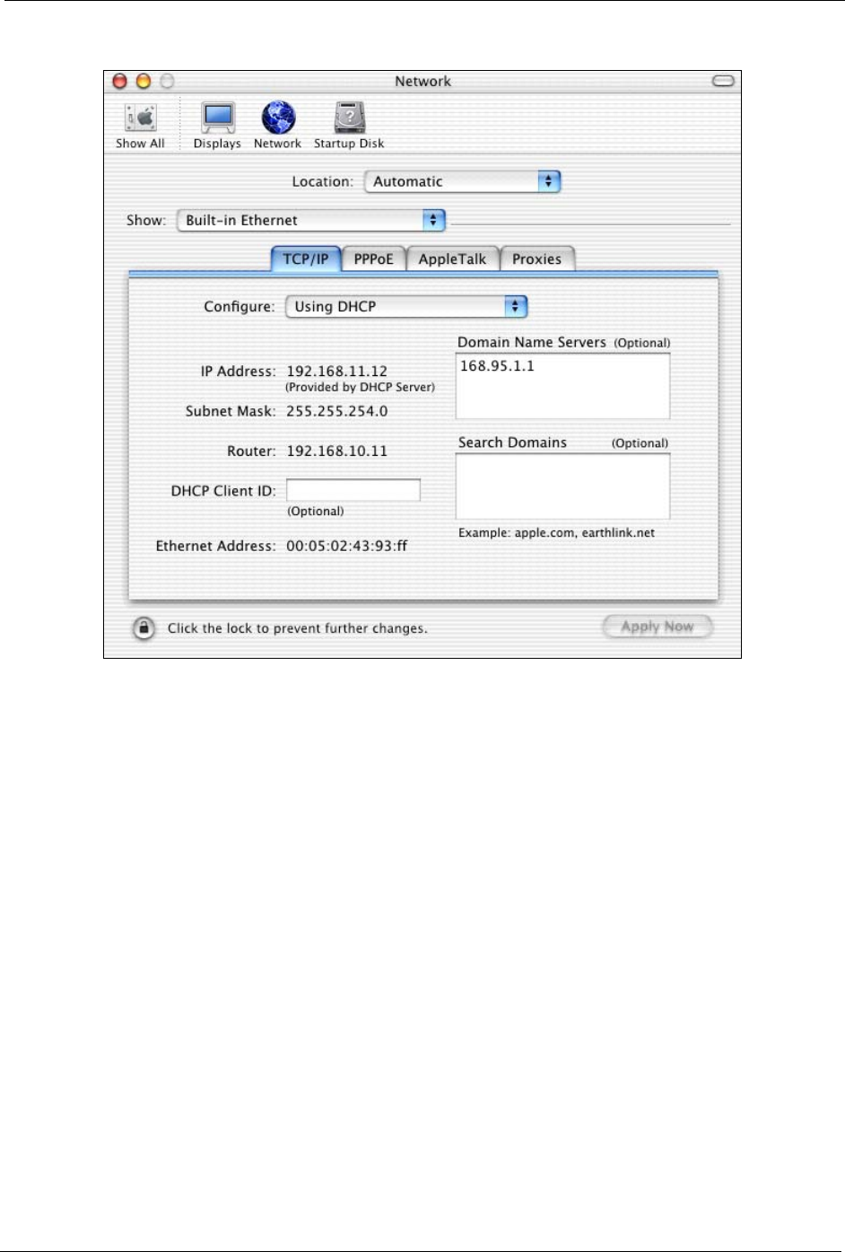
2Click Network in the icon bar.
• Select Automatic from the Location list.
• Select Built-in Ethernet from the Show list.
• Click the TCP/IP tab.
3For dynamically assigned settings, select Using DHCP from the Configure list.
G-470 User’s Guide
Appendix C 105
Figure 67 Macintosh OS X: Network
4For statically assigned settings, do the following:
•From the Configure box, select Manually.
• Type your IP address in the IP Address box.
• Type your subnet mask in the Subnet mask box.
• Type the IP address of your gateway in the Router address box if
you have one.
5Click Apply Now and close the window.
6Restart your computer (if prompted).
Verifying Settings
Check your TCP/IP properties in the Network window.

G-470 User’s Guide
106 Appendix C

G-470 User’s Guide
Index 107
Index
A
Access point 21, 24, 31
Access point. See also AP.
Address assignment 51
Advanced Encryption Standard (AES) 34, 91
AES 34
Antenna 22
connector 23
power output 87
AP 31
AP survey 49
AP. See also access point.
Applications 23
Authentication 32
Authentication method
auto 33
open system 33
shared key 33
Auto authentication 33
B
Backup 71
Basic Service Set 55
Bridge 21
Browser 35
BSS 55
C
CA 89
Cache 77
CCMP 34
Certificates 32
Certification Authority (CA) 32, 89
Certifications
Viewing 5
Channel 31, 56, 61
overlap 56
Clone MAC address 59
Configuration 35
backup 71
Copyright 3
Customer Support 8
D
Data encryption 61
Data rate 22, 87
management 59
DCHP 22
Default settings 49
Defaults 71
Digital ID 32
Dimensions 87
Direct Sequence Spread Spectrum (DSSS) 87
Disclaimer 3
Distribution System 56
Dynamic WEP Key Exchange 90
E
EAP Authentication 34
Encryption 32, 91
Encryption Type 33
Environmental Specifications 87
ESS 56
ESS IDentification 56
Ethernet 21, 22
Ethernet port 23
Examples 27
Extended Service Set 56
F
Factory defaults 71
FCC 4
Features 22
Feedback 19

G-470 User’s Guide
108 Index
Firmware 22, 72
upgrade 19
Fragmentation Threshold 58, 60
Frequency 31, 56, 87
Front panel 23
G
Getting started 21
Graphics icons key 20
H
Hardware 22
installation 19, 22
Hardware connection 19
Home network 21
Humidity 87
I
IEEE 802.11b 22
IEEE 802.11b/g 33
IEEE 802.11g 22
IEEE 802.11i 34
IEEE 802.1x 32, 34
Infrastructure 24, 55
Initialization vector (IV) 91
Installation 22
Interference 56, 58, 76
Interference Statement 4
Internet access 21
example 27
Internet browser 35
Internet connection setup 27
introduction 35
IP Address 35, 51
J
Java permissions 83
JavaScript 35, 81
L
LAN light 23
Lights 22, 23
Log in 39
M
MAC address cloning 59
Management 69
Media Access Control address 59
Message Integrity Check (MIC) 34, 91
MIC 34
Microsoft Internet Explorer 35
Mixed mode 59
Modulation 87
N
Netscape Navigator 35
Network 21
Network applications 23
Network card 36
Network number 51
Network overlap 31
O
Office network 21
Open system authentication 33
Oputput power
management 59
Output power 87
P
Pairwise Master Key (PMK) 91
Passphrase 33
Password 39, 49
Password phrase 33
Physical specifications 87
Ping 85

G-470 User’s Guide
Index 109
Pop-up windows 35, 78
Power 22
Power light 23
Power over Ethernet (PoE) 22
Power socket 23
Preamble 60
Preface 19
Pre-shared key 27
Private IP Address 51
Private key 32
Public key 32
Public-private key pairs 32
Pure B mode 59
Pure G mode 59
Q
Quick Start Guide 19, 22
R
Radio 56
Radio enable 59
Radio interference 76
Radio specifications 87
RADIUS 34
Rear panel 23
Registration 19
Related Documentation 19
Reset 23, 49
Restore 49, 71
Roaming 22, 24
RTS Threshold 57
RTS/CTS 57
RTS/CTS Threshold 60
Rx sensitivity 87
S
safety warnings 7
Scan 49
Screen resolution 35
Security 22, 33, 87
data encryption 33
Security Parameters 94
Service Set Identity 31, 57
Shared key authentication 33
Signal light 23
Signal strength 24, 61
Small office network 21
Software specifications 87
Specifications 87
SSID 27, 31, 57, 61
Statistics 42
Status 39
Status light 23
Subnet Mask 51
Subnet mask 35
Support 8
Support CD 19
Syntax conventions 19
System screen 51
T
TCP/IP 36, 51
Temperature 87
Temporal Key Integrity Protocol (TKIP) 34, 91
Testing connections 85
TKIP 34
Trademarks 3
Troubleshooting 75
Tutorial 27
U
URL 27, 39
User authentication 32, 92
User name 39, 49
V
Voltage 87

G-470 User’s Guide
110 Index
W
Warranty 6
Web Configurator 21, 35
accessing 39
Web configurator 35
WEP 33
default key 33
manual setup 33
passphrase 33
WEP (Wired Equivalent Privacy) 33
WEP key
automatic 33
manual 33
Wi-Fi Protected Access 34, 91
Wired Equivalent Privacy 33
Wired network 24
Wireless client 31
Wireless LAN 22
basics 56
introduction 31
security 32
Wireless LAN (WLAN) 31
Wireless mode 59
Wireless network 31
guidelines 31
Wireless security 32
compatibility 32
Wireless standard 87
WLAN
Security parameters 94
WLAN light 23
WPA 34, 91
WPA 2 34
WPA2 91
WPA2-Pre-Shared Key 91
WPA2-PSK 91
WPA-PSK 91
Z
ZyXEL glossary 19
ZyXEL Limited Warranty
Note 6
ZyXEL Web Site 19