ZyXEL Communications MAX207HW2 WiMAX MIMO 2.5GHz Indoor Multiple-user CPE User Manual Quick Start Guide
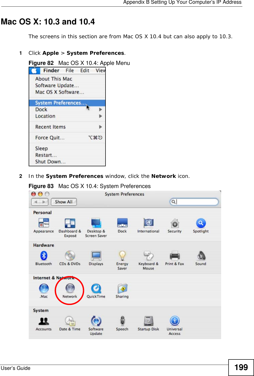
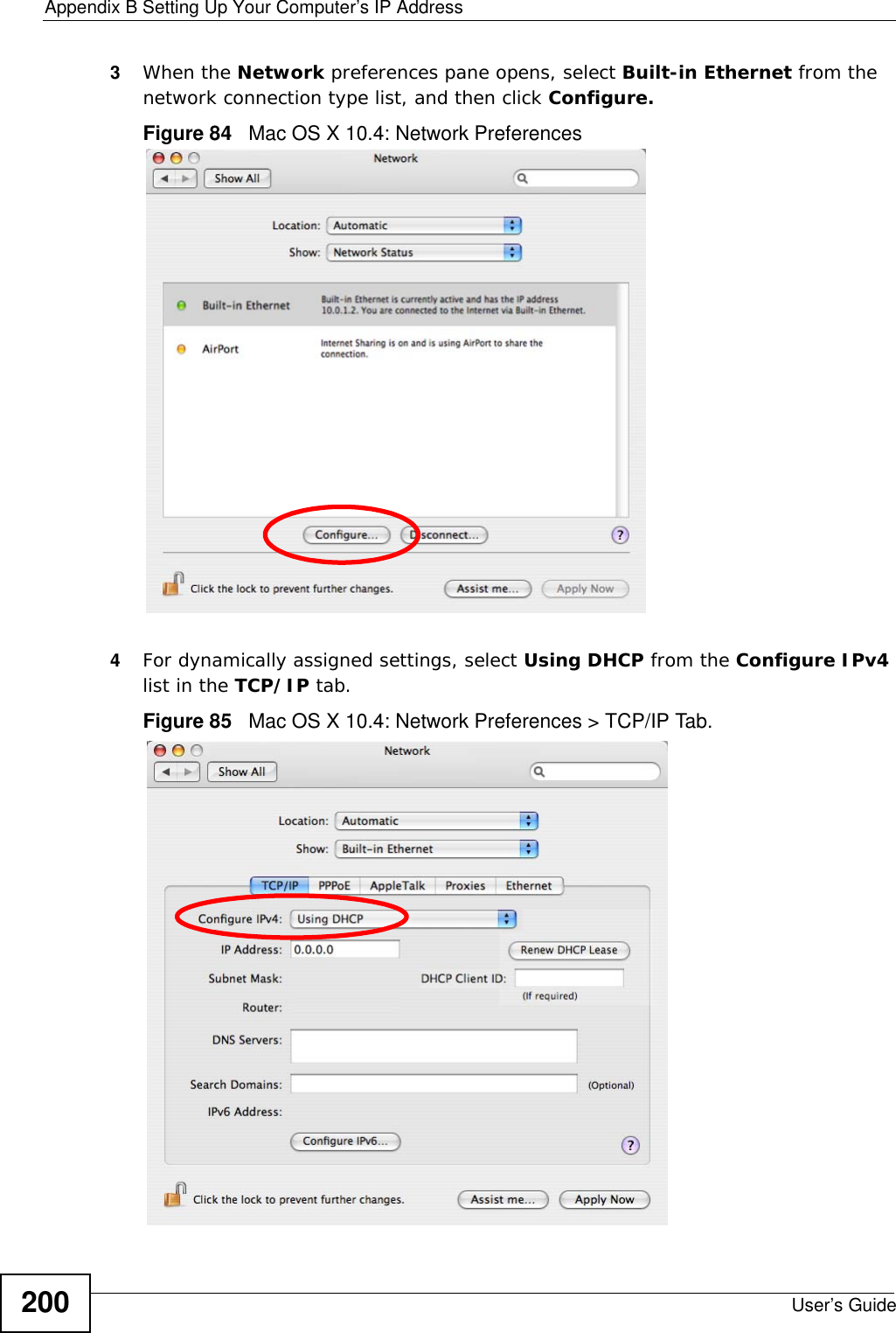
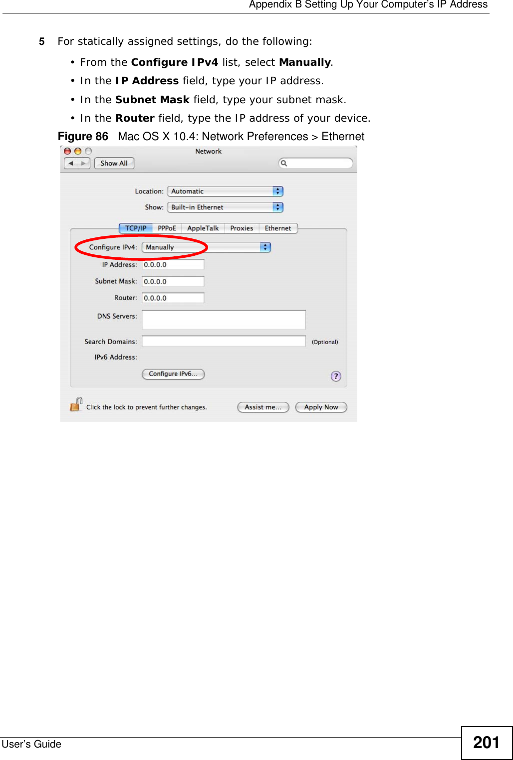
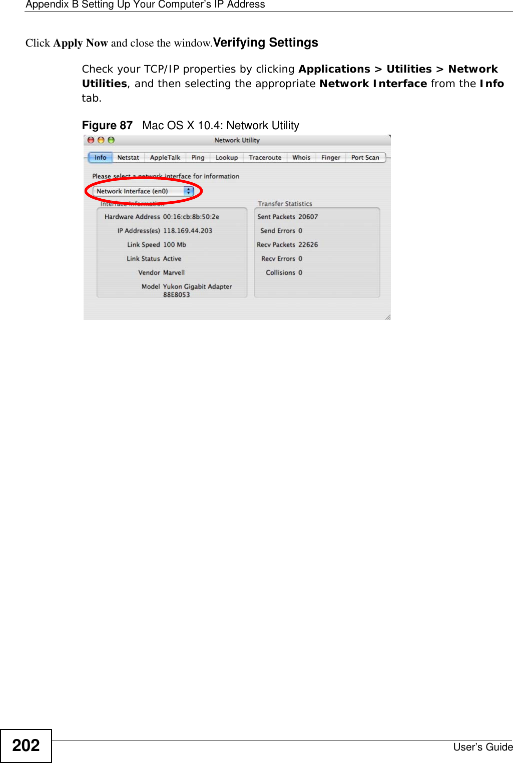
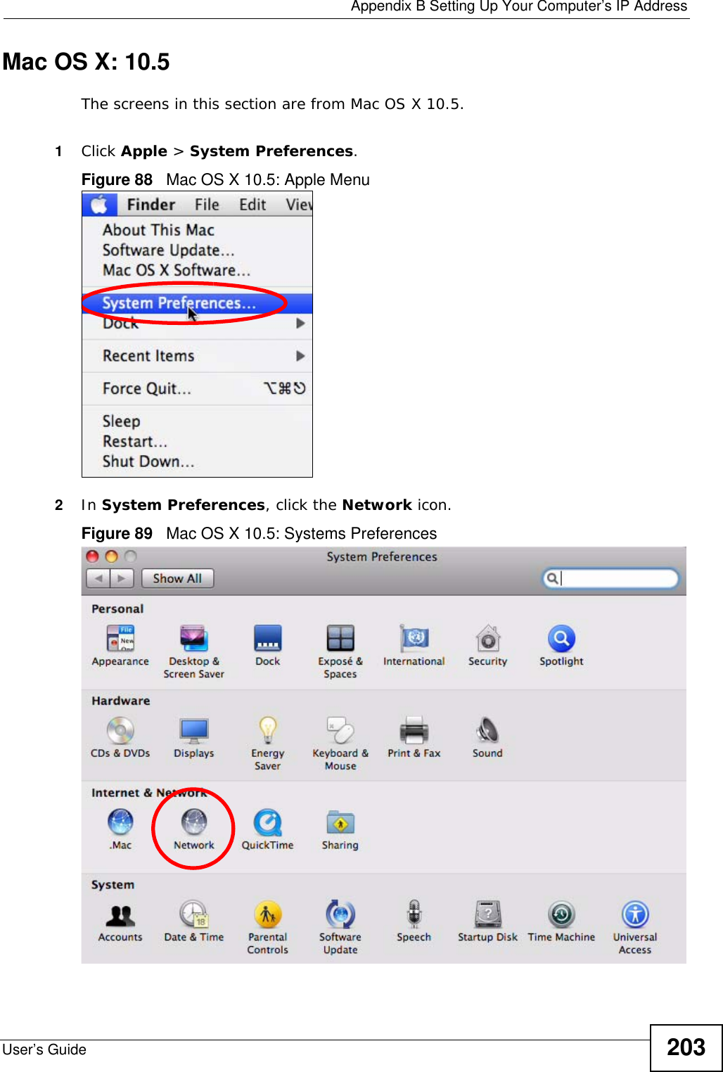
ZyXEL Communications Corporation WiMAX MIMO 2.5GHz Indoor Multiple-user CPE Quick Start Guide
Contents
- 1. Manual 1
- 2. Manual 2
- 3. Manual 3
Manual 2

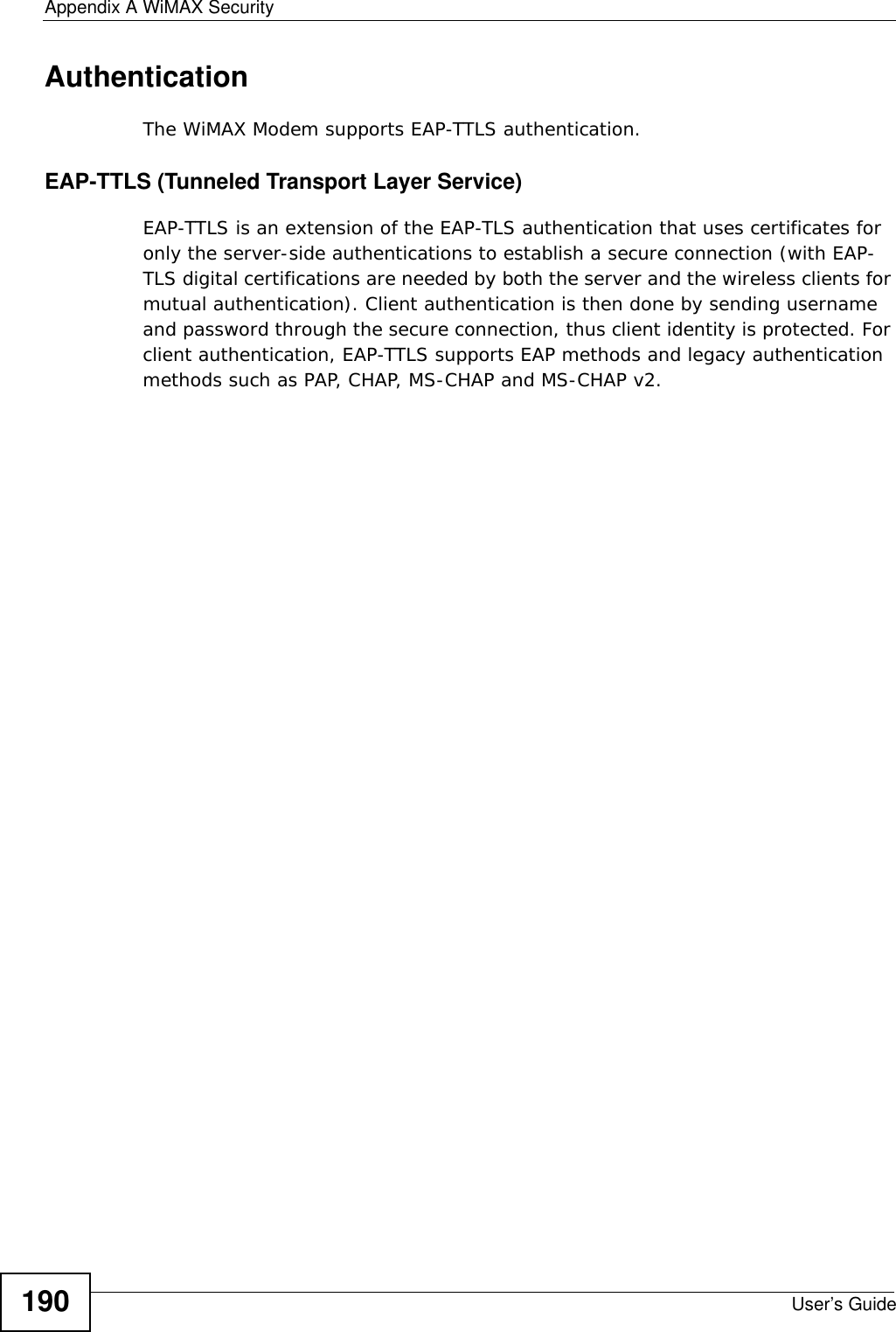
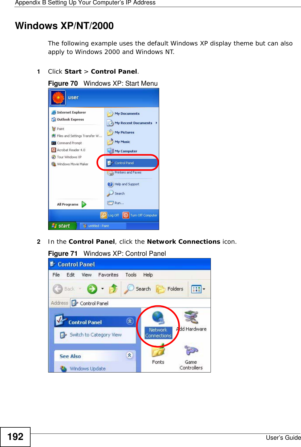
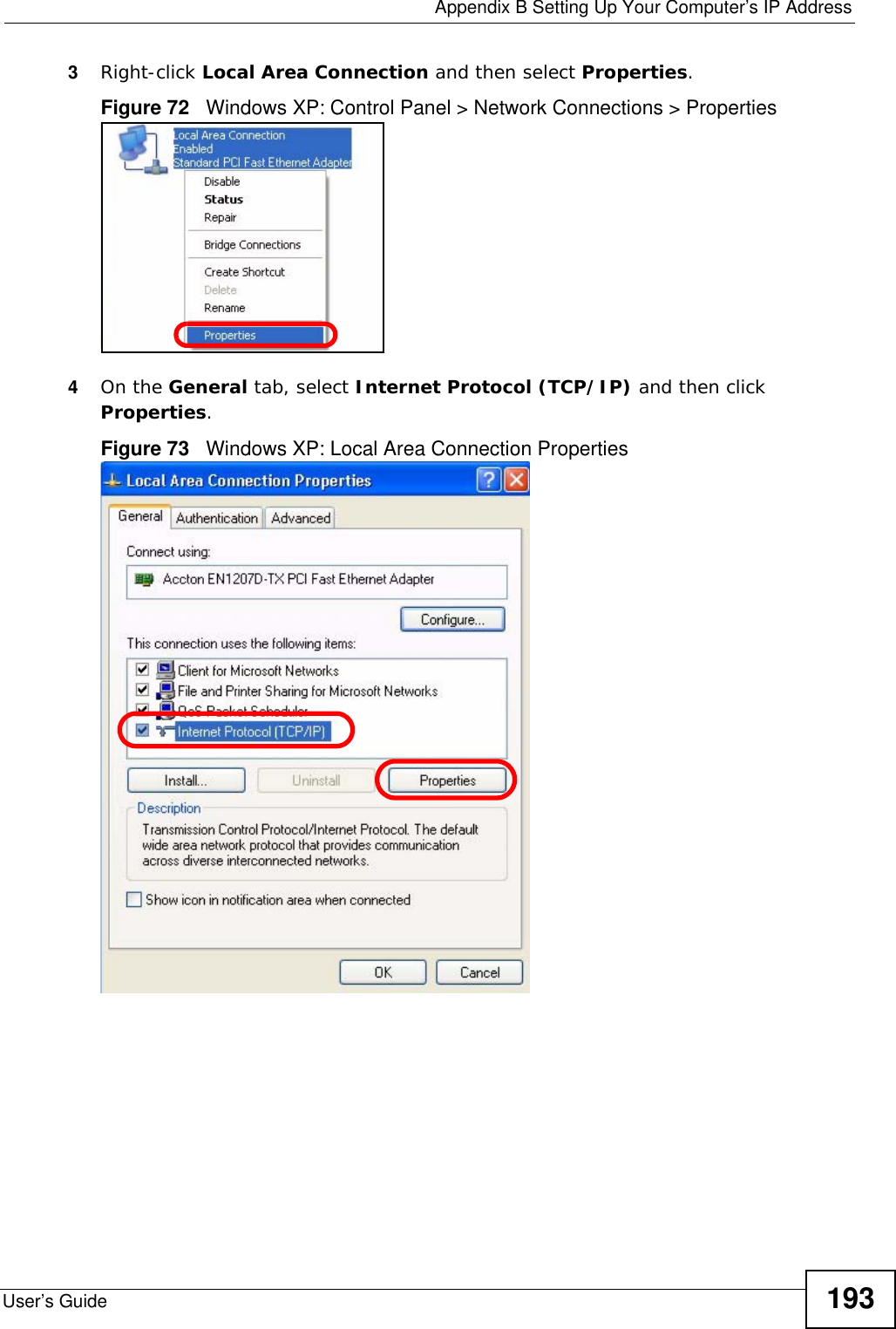
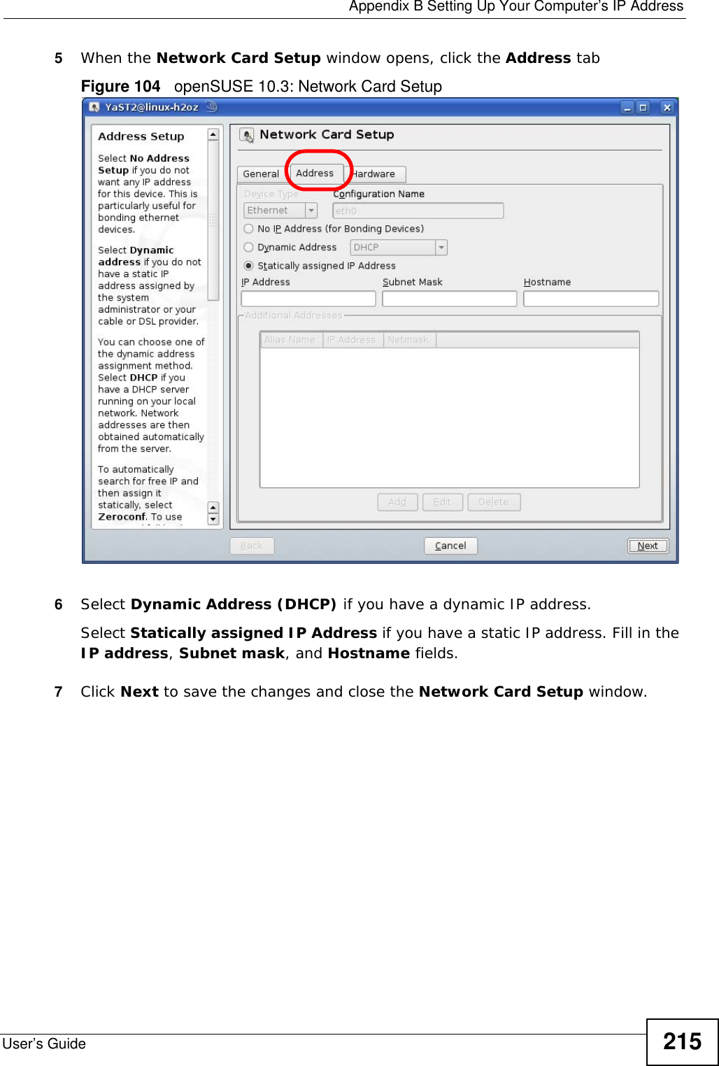
![Appendix B Setting Up Your Computer’s IP AddressUser’s Guide1945The Internet Protocol TCP/IP Properties window opens.Figure 74 Windows XP: Internet Protocol (TCP/IP) Properties6Select Obtain an IP address automatically if your network administrator or ISP assigns your IP address dynamically.Select Use the following IP Address and fill in the IP address, Subnet mask, and Default gateway fields if you have a static IP address that was assigned to you by your network administrator or ISP. You may also have to enter a Preferred DNS server and an Alternate DNS server, if that information was provided.7Click OK to close the Internet Protocol (TCP/IP) Properties window.Click OK to close the Local Area Connection Properties window.Verifying Settings1Click Start > All Programs > Accessories > Command Prompt.2In the Command Prompt window, type "ipconfig" and then press [ENTER]. You can also go to Start > Control Panel > Network Connections, right-click a network connection, click Status and then click the Support tab to view your IP address and connection information.](https://usermanual.wiki/ZyXEL-Communications/MAX207HW2.Manual-2/User-Guide-1139779-Page-13.png)
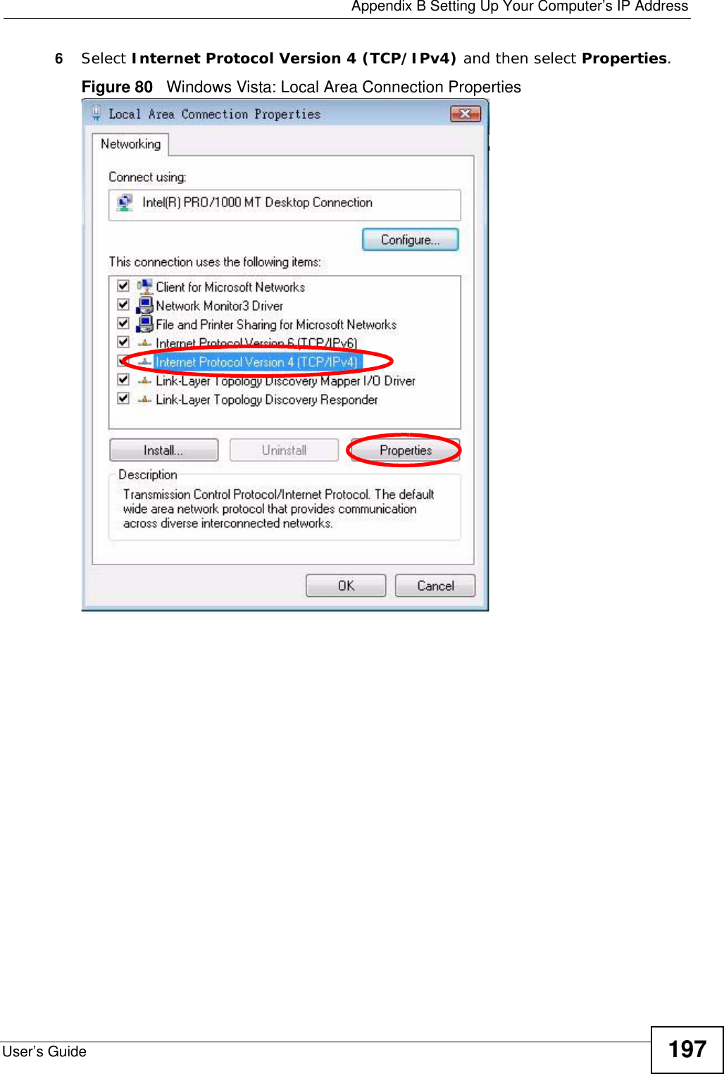
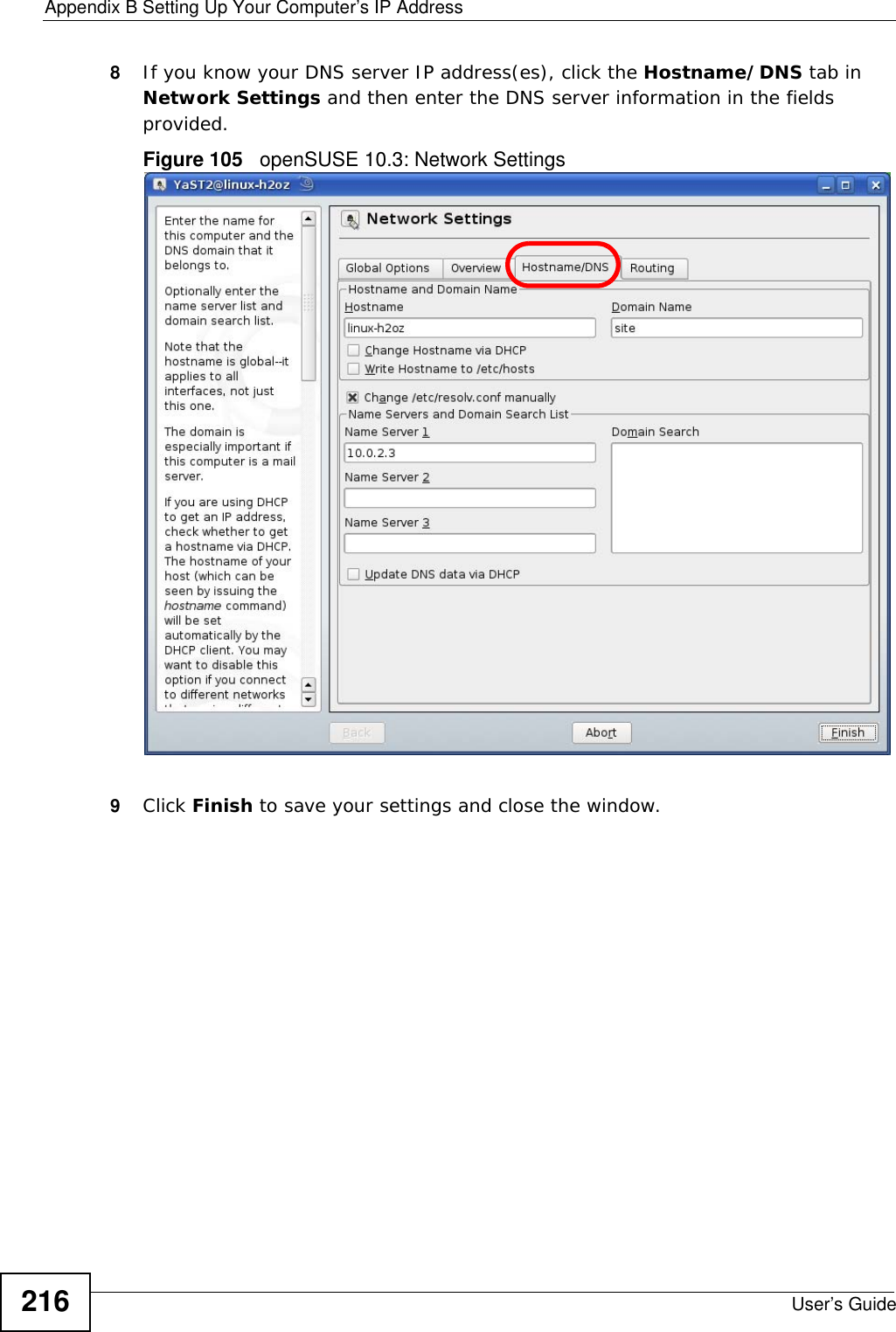
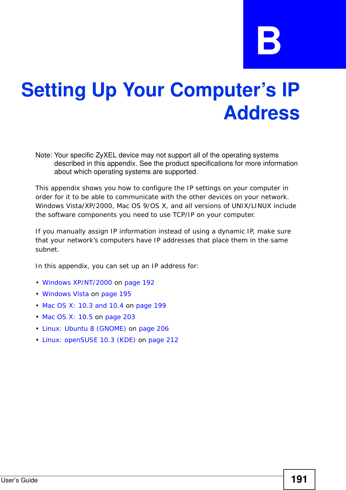
![Appendix B Setting Up Your Computer’s IP AddressUser’s Guide1987The Internet Protocol Version 4 (TCP/IPv4) Properties window opens.Figure 81 Windows Vista: Internet Protocol Version 4 (TCP/IPv4) Properties8Select Obtain an IP address automatically if your network administrator or ISP assigns your IP address dynamically.Select Use the following IP Address and fill in the IP address, Subnet mask, and Default gateway fields if you have a static IP address that was assigned to you by your network administrator or ISP. You may also have to enter a Preferred DNS server and an Alternate DNS server, if that information was provided.Click Advanced.9Click OK to close the Internet Protocol (TCP/IP) Properties window.Click OK to close the Local Area Connection Properties window.Verifying Settings1Click Start > All Programs > Accessories > Command Prompt.2In the Command Prompt window, type "ipconfig" and then press [ENTER]. You can also go to Start > Control Panel > Network Connections, right-click a network connection, click Status and then click the Support tab to view your IP address and connection information.](https://usermanual.wiki/ZyXEL-Communications/MAX207HW2.Manual-2/User-Guide-1139779-Page-17.png)