ZyXEL Communications MAX207HW2 WiMAX MIMO 2.5GHz Indoor Multiple-user CPE User Manual Quick Start Guide
ZyXEL Communications Corporation WiMAX MIMO 2.5GHz Indoor Multiple-user CPE Quick Start Guide
Contents
- 1. Manual 1
- 2. Manual 2
- 3. Manual 3
Manual 2

Chapter 18 Product Specifications
User’s Guide
182
Firmware update
enable / disable If your service provider uses this feature, you hear a recorded
message when you pick up the phone when new firmware is available
for your WiMAX Modem. Enter *99# in your phone’s keypad to have
the WiMAX Modem upgrade the firmware, or enter #99# to not
upgrade. If your service provider gave you different numbers to use,
enter them instead. If you enter the code to not upgrade, you can
make a call as normal. You will hear the recording again each time
you pick up the phone, until you upgrade.
Call waiting This feature allows you to hear an alert when you are already using
the phone and another person calls you. You can then either reject
the new incoming call, put your current call on hold and receive the
new incoming call, or end the current call and receive the new
incoming call.
Call forwarding With this feature, you can set the WiMAX Modem to forward calls to a
specified number, either unconditionally (always), when your number
is busy, or when you do not answer. You can also forward incoming
calls from one specified number to another.
Caller ID The WiMAX Modem supports caller ID, which allows you to see the
originating number of an incoming call (on a phone with a suitable
display).
REN A Ringer Equivalence Number (REN) is used to determine the number
of devices (like telephones or fax machines) that may be connected
to the telephone line. Your device has a REN of three, so it can
support three devices per telephone port.
QoS (Quality of
Service) Quality of Service (QoS) mechanisms help to provide better service
on a per-flow basis. Your device supports Type of Service (ToS)
tagging and Differentiated Services (DiffServ) tagging. This allows
the device to tag voice frames so they can be prioritized over the
network.
SIP ALG Your device is a SIP Application Layer Gateway (ALG). It allows VoIP
calls to pass through NAT for devices behind it (such as a SIP-based
VoIP software application on a computer).
Other Voice
Features SIP version 2 (Session Initiating Protocol RFC 3261)
SDP (Session Description Protocol RFC 2327)
RTP (RFC 1889)
RTCP (RFC 1890)
Voice codecs (coder/decoders) G.711, G.726, G.729
Fax and data modem discrimination
DTMF Detection and Generation
DTMF: In-band and Out-band traffic (RFC 2833),(PCM), (SIP INFO)
Point-to-point call establishment between two IADs
Quick dialing through predefined phone book, which maps the phone
dialing number and destination URL.
Flexible Dial Plan (RFC3525 section 7.1.14)
Table 69 Voice Features

Chapter 18 Product Specifications
User’s Guide 183
Note: To take full advantage of the supplementary phone services available through
the WiMAX Modem's phone port, you may need to subscribe to the services
from your voice account service provider.
Not all features are supported by all service providers. Consult your service
provider for more information.
Table 70 Star (*) and Pound (#) Code Support
*0 Wireless Operator Services
*2 Customer Care Access
*66 Repeat Dialing
*67 Plus the 10 digit phone number to block Caller ID on a single call
basis
*69 Return last call received
*70 Followed by the 10 digit phone number to cancel Call Waiting on a
single call basis
*72 Activate Call Forwarding (*72 followed by the 10 digit phone number
that is requesting call forwarding service)
*720 Activate Call Forwarding (*720 followed by the 10 digit phone number
that is requesting deactivation of call forwarding service)
*73 Plus the forward to phone number to activate Call Forwarding No
Answer (no VM service plan)
*730 Deactivate Call Forwarding No Answer
*740 Plus the forward to phone number to activate Call Forwarding Busy
(no VM service plan)
*911/911 Emergency phone number (same as dialing 911)
*411/411 Wireless Information Services

Chapter 18 Product Specifications
User’s Guide
184


186

User’s Guide 187
APPENDIX A
WiMAX Security
Wireless security is vital to protect your wireless communications. Without it,
information transmitted over the wireless network would be accessible to any
networking device within range.
User Authentication and Data Encryption
The WiMAX (IEEE 802.16) standard employs user authentication and encryption to
ensure secured communication at all times.
User authentication is the process of confirming a user’s identity and level of
authorization. Data encryption is the process of encoding information so that it
cannot be read by anyone who does not know the code.
WiMAX uses PKMv2 (Privacy Key Management version 2) for authentication, and
CCMP (Counter Mode with Cipher Block Chaining Message Authentication Protocol)
for data encryption.
WiMAX supports EAP (Extensible Authentication Protocol, RFC 2486) which allows
additional authentication methods to be deployed with no changes to the base
station or the mobile or subscriber stations.
PKMv2
PKMv2 is a procedure that allows authentication of a mobile or subscriber station
and negotiation of a public key to encrypt traffic between the MS/SS and the base
station. PKMv2 uses standard EAP methods such as Transport Layer Security
(EAP-TLS) or Tunneled TLS (EAP-TTLS) for secure communication.
In cryptography, a ‘key’ is a piece of information, typically a string of random
numbers and letters, that can be used to ‘lock’ (encrypt) or ‘unlock’ (decrypt) a
message. Public key encryption uses key pairs, which consist of a public (freely
available) key and a private (secret) key. The public key is used for encryption and
the private key is used for decryption. You can decrypt a message only if you have
the private key. Public key certificates (or ‘digital IDs’) allow users to verify each
other’s identity.

Appendix A WiMAX Security
User’s Guide
188
RADIUS
RADIUS is based on a client-server model that supports authentication,
authorization and accounting. The base station is the client and the server is the
RADIUS server. The RADIUS server handles the following tasks:
• Authentication
Determines the identity of the users.
• Authorization
Determines the network services available to authenticated users once they are
connected to the network.
•Accounting
Keeps track of the client’s network activity.
RADIUS is a simple package exchange in which your base station acts as a
message relay between the MS/SS and the network RADIUS server.
Types of RADIUS Messages
The following types of RADIUS messages are exchanged between the base station
and the RADIUS server for user authentication:
• Access-Request
Sent by an base station requesting authentication.
• Access-Reject
Sent by a RADIUS server rejecting access.
• Access-Accept
Sent by a RADIUS server allowing access.
• Access-Challenge
Sent by a RADIUS server requesting more information in order to allow access.
The base station sends a proper response from the user and then sends another
Access-Request message.
The following types of RADIUS messages are exchanged between the base station
and the RADIUS server for user accounting:
•Accounting-Request
Sent by the base station requesting accounting.
• Accounting-Response
Sent by the RADIUS server to indicate that it has started or stopped accounting.
In order to ensure network security, the access point and the RADIUS server use a
shared secret key, which is a password they both know. The key is not sent over

Appendix A WiMAX Security
User’s Guide 189
the network. In addition to the shared key, password information exchanged is
also encrypted to protect the network from unauthorized access.
Diameter
Diameter (RFC 3588) is a type of AAA server that provides several improvements
over RADIUS in efficiency, security, and support for roaming.
Security Association
The set of information about user authentication and data encryption between two
computers is known as a security association (SA). In a WiMAX network, the
process of security association has three stages.
• Authorization request and reply
The MS/SS presents its public certificate to the base station. The base station
verifies the certificate and sends an authentication key (AK) to the MS/SS.
• Key request and reply
The MS/SS requests a transport encryption key (TEK) which the base station
generates and encrypts using the authentication key.
• Encrypted traffic
The MS/SS decrypts the TEK (using the authentication key). Both stations can
now securely encrypt and decrypt the data flow.
CCMP
All traffic in a WiMAX network is encrypted using CCMP (Counter Mode with Cipher
Block Chaining Message Authentication Protocol). CCMP is based on the 128-bit
Advanced Encryption Standard (AES) algorithm.
‘Counter mode’ refers to the encryption of each block of plain text with an
arbitrary number, known as the counter. This number changes each time a block
of plain text is encrypted. Counter mode avoids the security weakness of repeated
identical blocks of encrypted text that makes encrypted data vulnerable to
pattern-spotting.
‘Cipher Block Chaining Message Authentication’ (also known as CBC-MAC) ensures
message integrity by encrypting each block of plain text in such a way that its
encryption is dependent on the block before it. This series of ‘chained’ blocks
creates a message authentication code (MAC or CMAC) that ensures the encrypted
data has not been tampered with.

Appendix A WiMAX Security
User’s Guide
190
Authentication
The WiMAX Modem supports EAP-TTLS authentication.
EAP-TTLS (Tunneled Transport Layer Service)
EAP-TTLS is an extension of the EAP-TLS authentication that uses certificates for
only the server-side authentications to establish a secure connection (with EAP-
TLS digital certifications are needed by both the server and the wireless clients for
mutual authentication). Client authentication is then done by sending username
and password through the secure connection, thus client identity is protected. For
client authentication, EAP-TTLS supports EAP methods and legacy authentication
methods such as PAP, CHAP, MS-CHAP and MS-CHAP v2.

User’s Guide 191
APPENDIX B
Setting Up Your Computer’s IP
Address
Note: Your specific ZyXEL device may not support all of the operating systems
described in this appendix. See the product specifications for more information
about which operating systems are supported.
This appendix shows you how to configure the IP settings on your computer in
order for it to be able to communicate with the other devices on your network.
Windows Vista/XP/2000, Mac OS 9/OS X, and all versions of UNIX/LINUX include
the software components you need to use TCP/IP on your computer.
If you manually assign IP information instead of using a dynamic IP, make sure
that your network’s computers have IP addresses that place them in the same
subnet.
In this appendix, you can set up an IP address for:
•Windows XP/NT/2000 on page 192
•Windows Vista on page 195
•Mac OS X: 10.3 and 10.4 on page 199
•Mac OS X: 10.5 on page 203
•Linux: Ubuntu 8 (GNOME) on page 206
•Linux: openSUSE 10.3 (KDE) on page 212
Appendix B Setting Up Your Computer’s IP Address
User’s Guide
192
Windows XP/NT/2000
The following example uses the default Windows XP display theme but can also
apply to Windows 2000 and Windows NT.
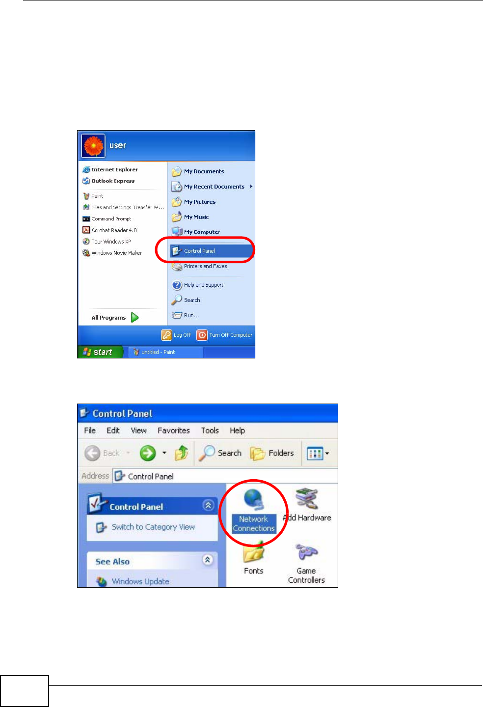
1Click Start > Control Panel.
Figure 70 Windows XP: Start Menu
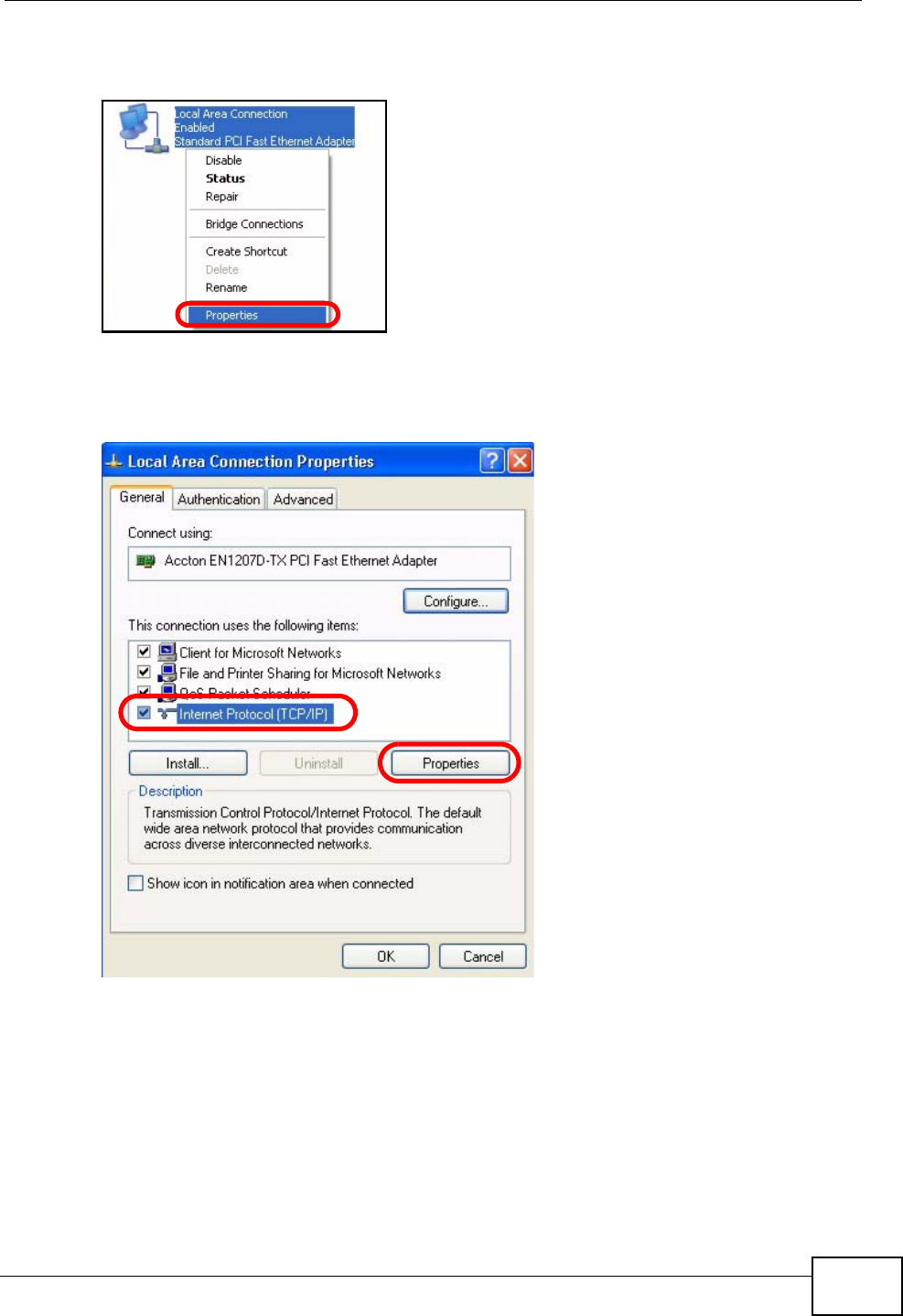
2In the Control Panel, click the Network Connections icon.
Figure 71 Windows XP: Control Panel
Appendix B Setting Up Your Computer’s IP Address
User’s Guide 193
3Right-click Local Area Connection and then select Properties.
Figure 72 Windows XP: Control Panel > Network Connections > Properties
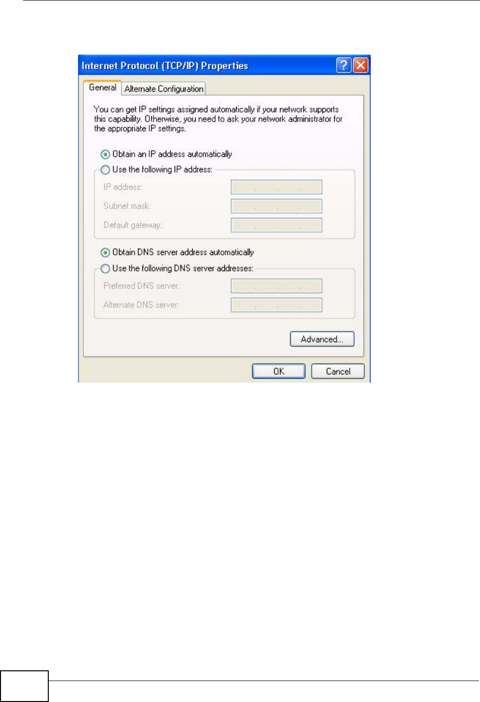
4On the General tab, select Internet Protocol (TCP/IP) and then click
Properties.
Figure 73 Windows XP: Local Area Connection Properties
Appendix B Setting Up Your Computer’s IP Address
User’s Guide
194
5The Internet Protocol TCP/IP Properties window opens.
Figure 74 Windows XP: Internet Protocol (TCP/IP) Properties
6Select Obtain an IP address automatically if your network administrator or ISP
assigns your IP address dynamically.
Select Use the following IP Address and fill in the IP address, Subnet mask,
and Default gateway fields if you have a static IP address that was assigned to
you by your network administrator or ISP. You may also have to enter a Preferred
DNS server and an Alternate DNS server, if that information was provided.
7Click OK to close the Internet Protocol (TCP/IP) Properties window.
Click OK to close the Local Area Connection Properties window.Verifying Settings
1Click Start > All Programs > Accessories > Command Prompt.
2In the Command Prompt window, type "ipconfig" and then press [ENTER].
You can also go to Start > Control Panel > Network Connections, right-click a
network connection, click Status and then click the Support tab to view your IP
address and connection information.
Appendix B Setting Up Your Computer’s IP Address
User’s Guide 195
Windows Vista
This section shows screens from Windows Vista Professional.
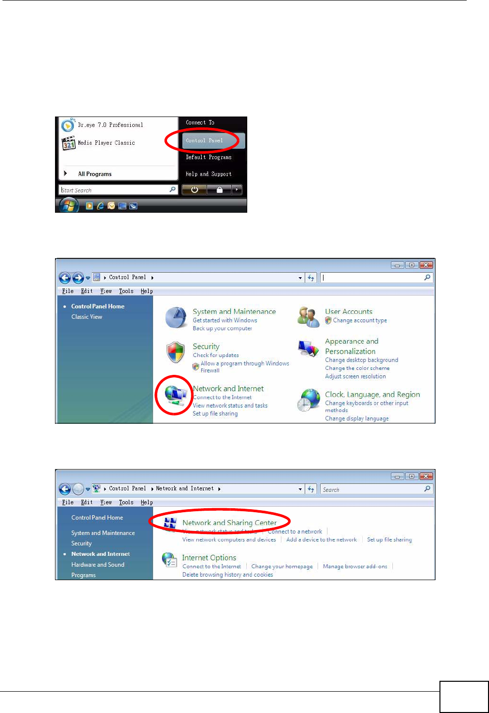
1Click Start > Control Panel.
Figure 75 Windows Vista: Start Menu
2In the Control Panel, click the Network and Internet icon.
Figure 76 Windows Vista: Control Panel
3Click the Network and Sharing Center icon.
Figure 77 Windows Vista: Network And Internet
Appendix B Setting Up Your Computer’s IP Address
User’s Guide
196
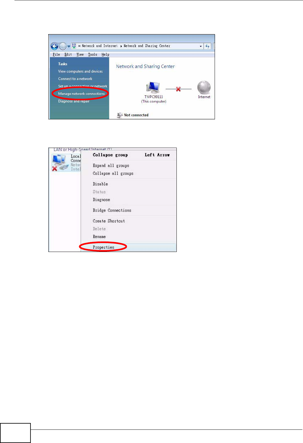
4Click Manage network connections.
Figure 78 Windows Vista: Network and Sharing Center
5Right-click Local Area Connection and then select Properties.
Figure 79 Windows Vista: Network and Sharing Center
Note: During this procedure, click Continue whenever Windows displays a screen
saying that it needs your permission to continue.
Appendix B Setting Up Your Computer’s IP Address
User’s Guide 197
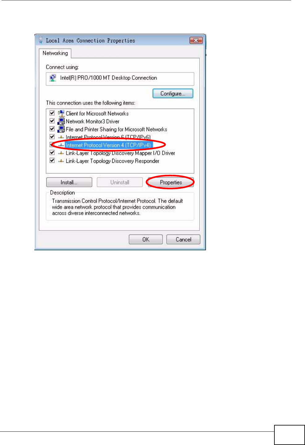
6Select Internet Protocol Version 4 (TCP/IPv4) and then select Properties.
Figure 80 Windows Vista: Local Area Connection Properties
Appendix B Setting Up Your Computer’s IP Address
User’s Guide
198
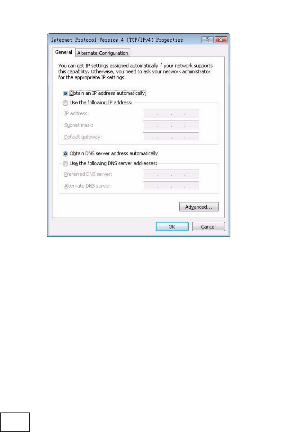
7The Internet Protocol Version 4 (TCP/IPv4) Properties window opens.
Figure 81 Windows Vista: Internet Protocol Version 4 (TCP/IPv4) Properties
8Select Obtain an IP address automatically if your network administrator or ISP
assigns your IP address dynamically.
Select Use the following IP Address and fill in the IP address, Subnet mask,
and Default gateway fields if you have a static IP address that was assigned to
you by your network administrator or ISP. You may also have to enter a Preferred
DNS server and an Alternate DNS server, if that information was
provided.Click Advanced.
9Click OK to close the Internet Protocol (TCP/IP) Properties window.
Click OK to close the Local Area Connection Properties window.Verifying Settings
1Click Start > All Programs > Accessories > Command Prompt.
2In the Command Prompt window, type "ipconfig" and then press [ENTER].
You can also go to Start > Control Panel > Network Connections, right-click a
network connection, click Status and then click the Support tab to view your IP
address and connection information.
Appendix B Setting Up Your Computer’s IP Address
User’s Guide 199
Mac OS X: 10.3 and 10.4
The screens in this section are from Mac OS X 10.4 but can also apply to 10.3.
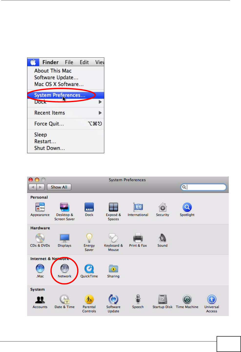
1Click Apple > System Preferences.
Figure 82 Mac OS X 10.4: Apple Menu
2In the System Preferences window, click the Network icon.
Figure 83 Mac OS X 10.4: System Preferences
Appendix B Setting Up Your Computer’s IP Address
User’s Guide
200
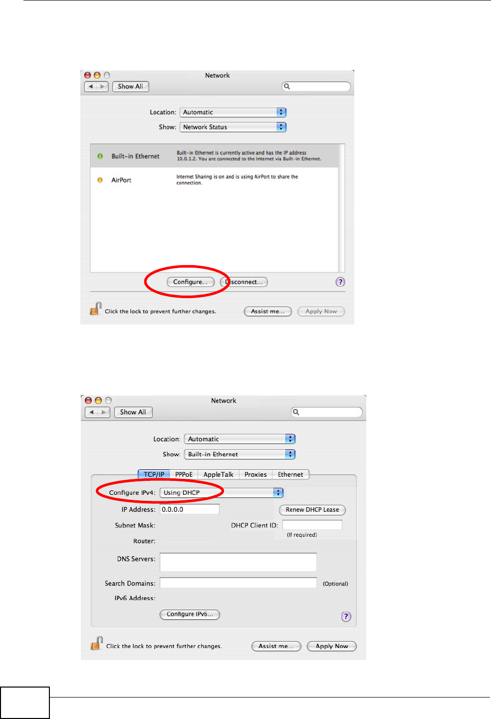
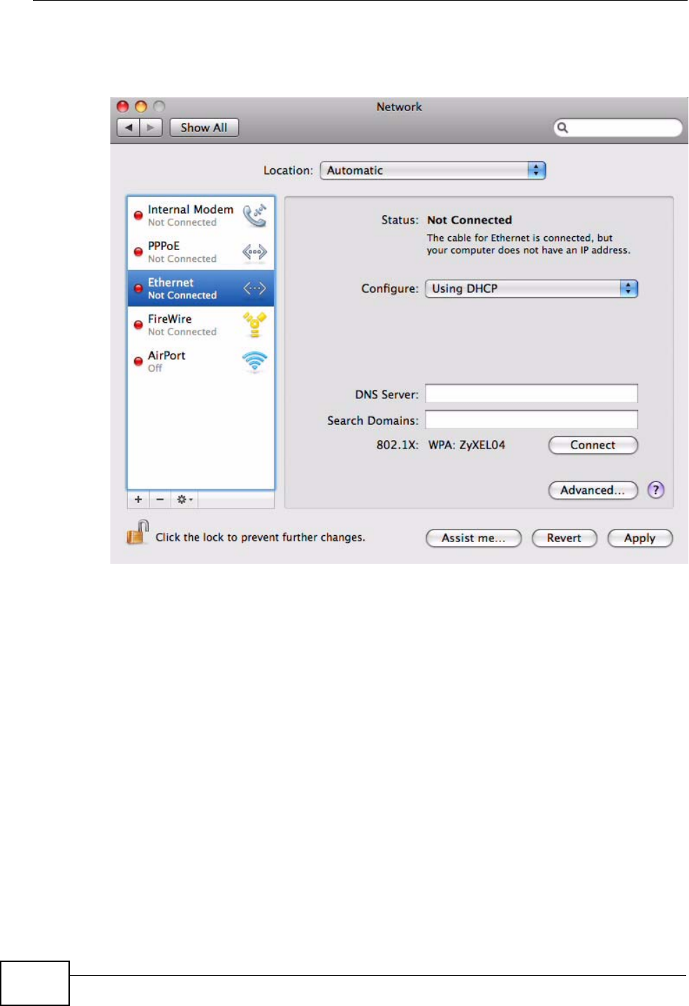
3When the Network preferences pane opens, select Built-in Ethernet from the
network connection type list, and then click Configure.
Figure 84 Mac OS X 10.4: Network Preferences
4For dynamically assigned settings, select Using DHCP from the Configure IPv4
list in the TCP/IP tab.
Figure 85 Mac OS X 10.4: Network Preferences > TCP/IP Tab.
Appendix B Setting Up Your Computer’s IP Address
User’s Guide 201
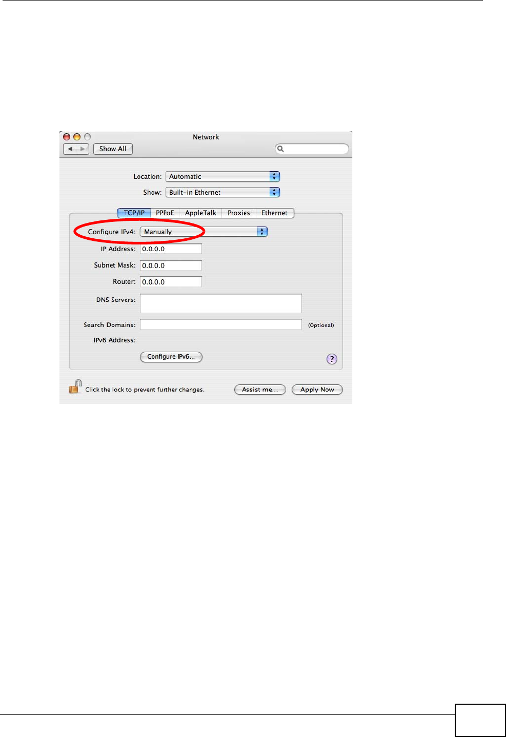
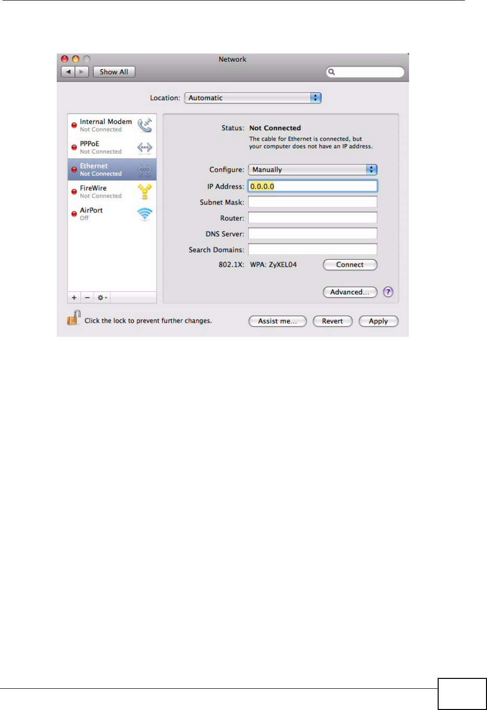
5For statically assigned settings, do the following:
•From the Configure IPv4 list, select Manually.
•In the IP Address field, type your IP address.
•In the Subnet Mask field, type your subnet mask.
•In the Router field, type the IP address of your device.
Figure 86 Mac OS X 10.4: Network Preferences > Ethernet
Appendix B Setting Up Your Computer’s IP Address
User’s Guide
202
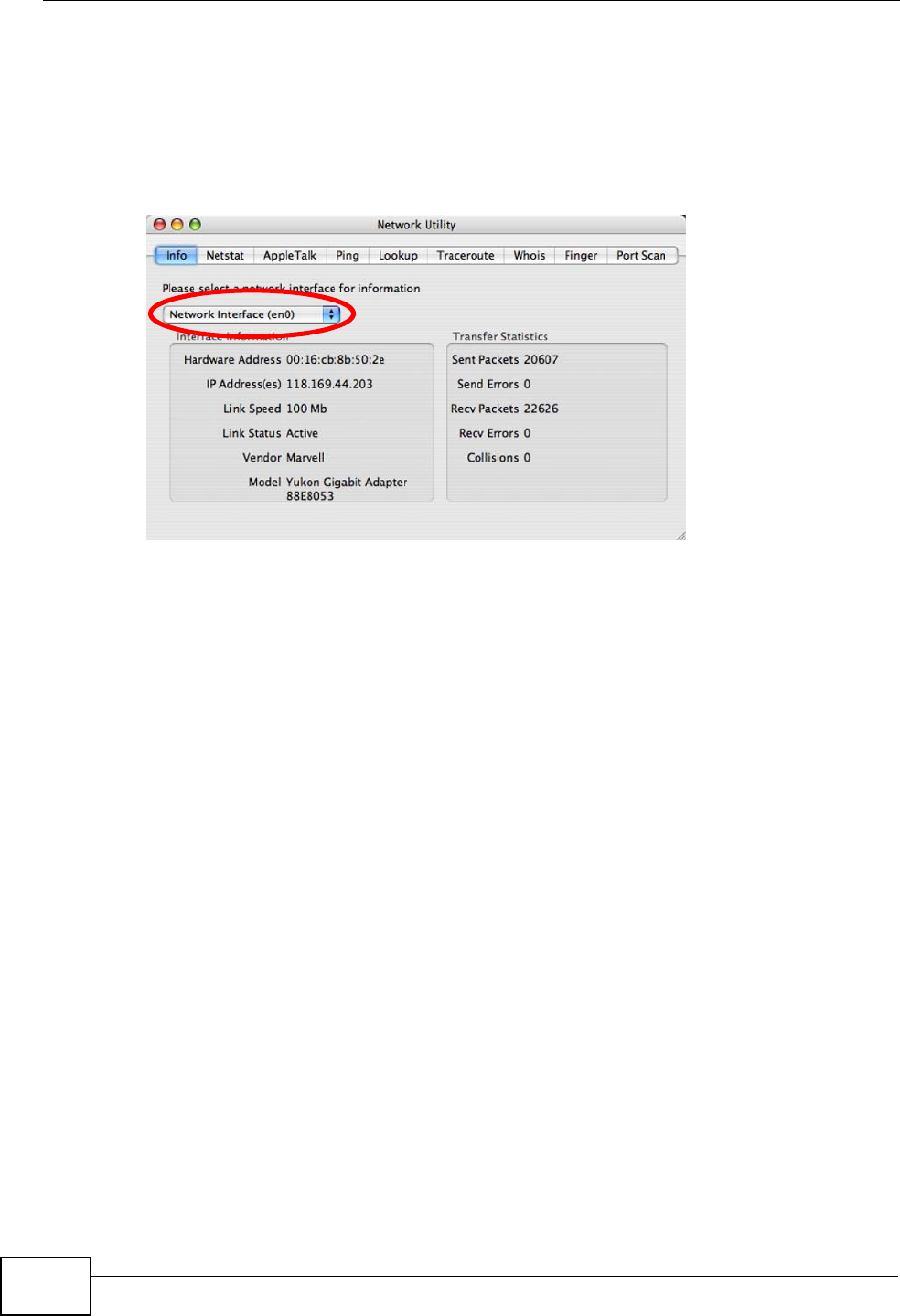
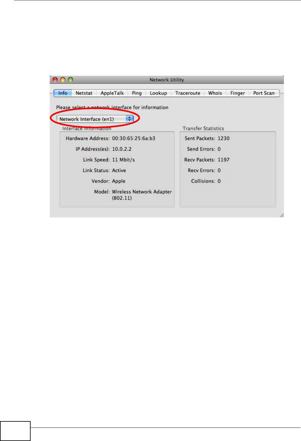
Click Apply Now and close the window.Verifying Settings
Check your TCP/IP properties by clicking Applications > Utilities > Network
Utilities, and then selecting the appropriate Network Interface from the Info
tab.
Figure 87 Mac OS X 10.4: Network Utility
Appendix B Setting Up Your Computer’s IP Address
User’s Guide 203
Mac OS X: 10.5
The screens in this section are from Mac OS X 10.5.
1Click Apple > System Preferences.
Figure 88 Mac OS X 10.5: Apple Menu
2In System Preferences, click the Network icon.
Figure 89 Mac OS X 10.5: Systems Preferences
Appendix B Setting Up Your Computer’s IP Address
User’s Guide
204
3When the Network preferences pane opens, select Ethernet from the list of
available connection types.
Figure 90 Mac OS X 10.5: Network Preferences > Ethernet
4From the Configure list, select Using DHCP for dynamically assigned settings.
5For statically assigned settings, do the following:
•From the Configure list, select Manually.
•In the IP Address field, enter your IP address.
•In the Subnet Mask field, enter your subnet mask.
Appendix B Setting Up Your Computer’s IP Address
User’s Guide 205
•In the Router field, enter the IP address of your WiMAX Modem.
Figure 91 Mac OS X 10.5: Network Preferences > Ethernet
6Click Apply and close the window.
Appendix B Setting Up Your Computer’s IP Address
User’s Guide
206
Verifying Settings
Check your TCP/IP properties by clicking Applications > Utilities > Network
Utilities, and then selecting the appropriate Network interface from the Info
tab.
Figure 92 Mac OS X 10.5: Network Utility
Linux: Ubuntu 8 (GNOME)
This section shows you how to configure your computer’s TCP/IP settings in the
GNU Object Model Environment (GNOME) using the Ubuntu 8 Linux distribution.
The procedure, screens and file locations may vary depending on your specific
distribution, release version, and individual configuration. The following screens
use the default Ubuntu 8 installation.
Note: Make sure you are logged in as the root administrator.
Follow the steps below to configure your computer IP address in GNOME:
Appendix B Setting Up Your Computer’s IP Address
User’s Guide 207
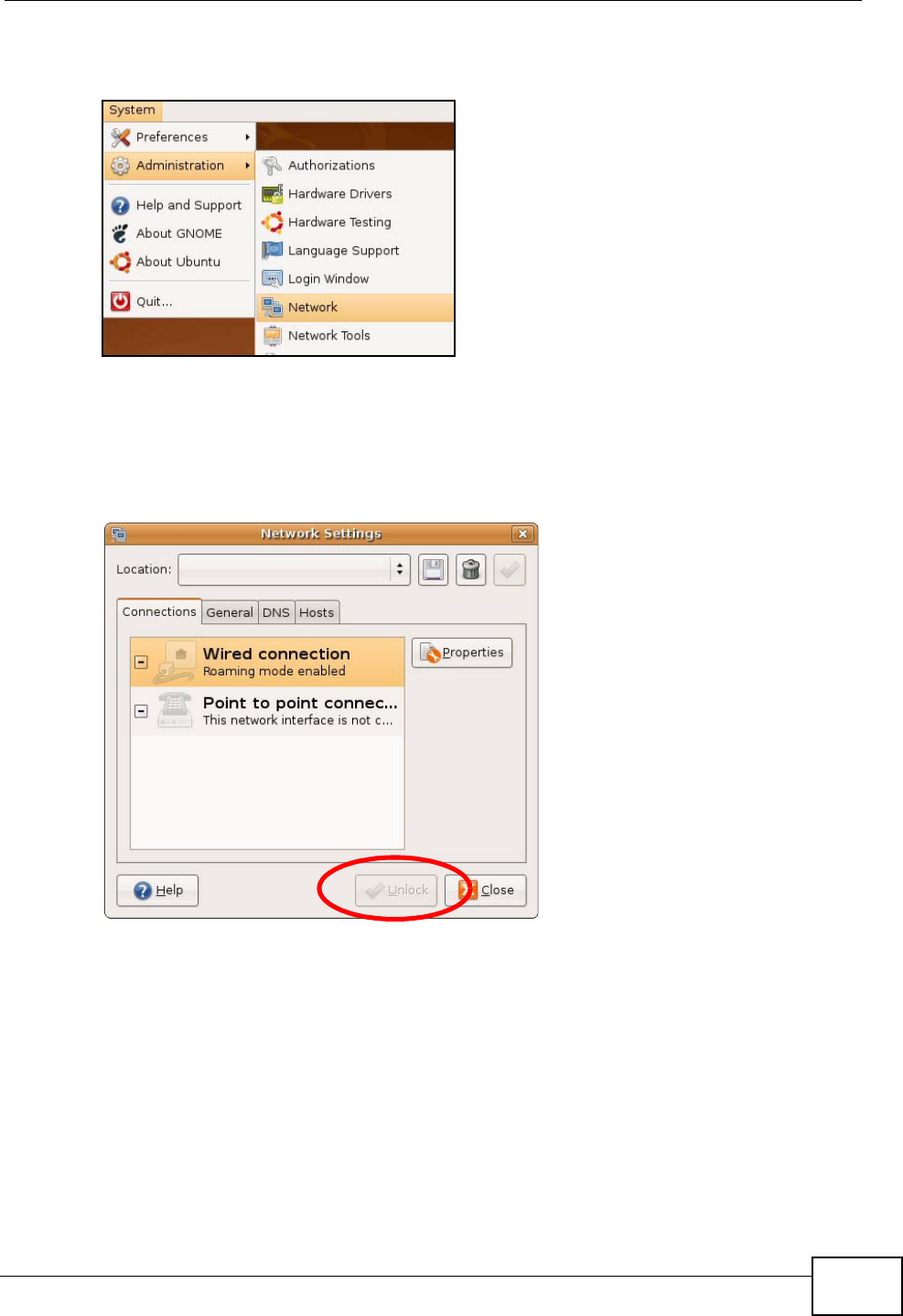
1Click System > Administration > Network.
Figure 93 Ubuntu 8: System > Administration Menu
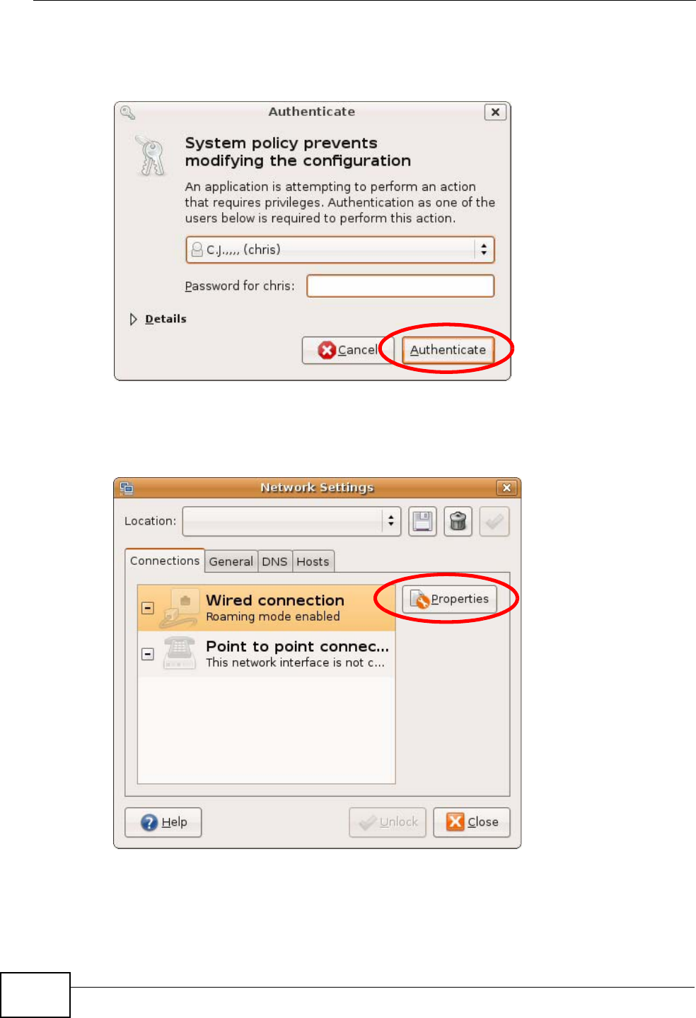
2When the Network Settings window opens, click Unlock to open the
Authenticate window. (By default, the Unlock button is greyed out until clicked.)
You cannot make changes to your configuration unless you first enter your admin
password.
Figure 94 Ubuntu 8: Network Settings > Connections
Appendix B Setting Up Your Computer’s IP Address
User’s Guide
208
3In the Authenticate window, enter your admin account name and password then
click the Authenticate button.
Figure 95 Ubuntu 8: Administrator Account Authentication
4In the Network Settings window, select the connection that you want to
configure, then click Properties.
Figure 96 Ubuntu 8: Network Settings > Connections
Appendix B Setting Up Your Computer’s IP Address
User’s Guide 209
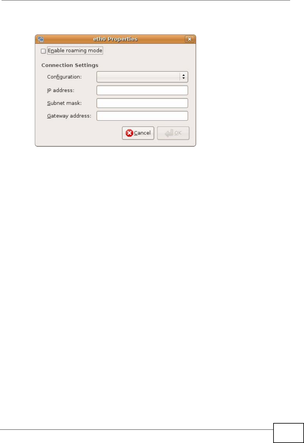
5The Properties dialog box opens.
Figure 97 Ubuntu 8: Network Settings > Properties
•In the Configuration list, select Automatic Configuration (DHCP) if you
have a dynamic IP address.
•In the Configuration list, select Static IP address if you have a static IP
address. Fill in the IP address, Subnet mask, and Gateway address fields.
6Click OK to save the changes and close the Properties dialog box and return to
the Network Settings screen.
Appendix B Setting Up Your Computer’s IP Address
User’s Guide
210
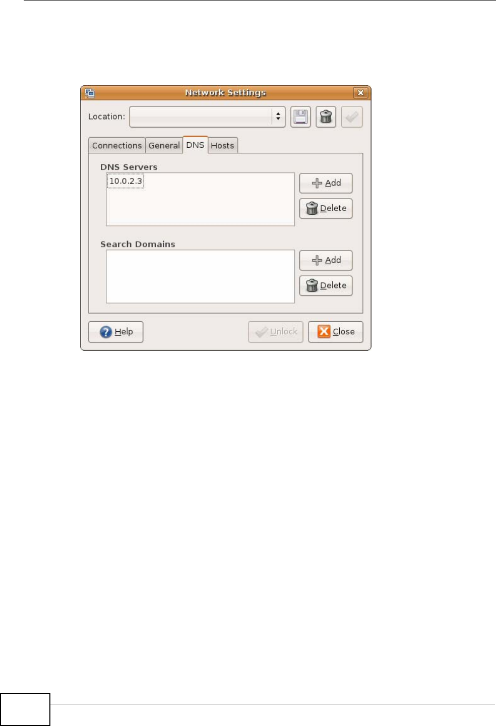
7If you know your DNS server IP address(es), click the DNS tab in the Network
Settings window and then enter the DNS server information in the fields
provided.
Figure 98 Ubuntu 8: Network Settings > DNS
8Click the Close button to apply the changes.
Verifying Settings
Check your TCP/IP properties by clicking System > Administration > Network
Tools, and then selecting the appropriate Network device from the Devices
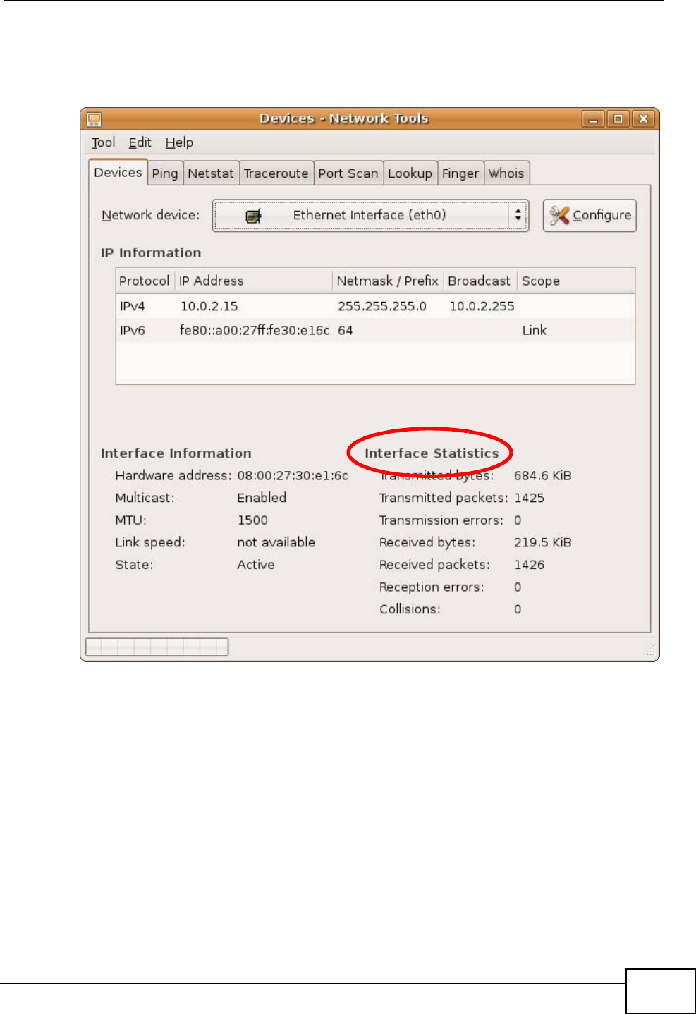
Appendix B Setting Up Your Computer’s IP Address
User’s Guide 211
tab. The Interface Statistics column shows data if your connection is working
properly.
Figure 99 Ubuntu 8: Network Tools
Appendix B Setting Up Your Computer’s IP Address
User’s Guide
212
Linux: openSUSE 10.3 (KDE)
This section shows you how to configure your computer’s TCP/IP settings in the K
Desktop Environment (KDE) using the openSUSE 10.3 Linux distribution. The
procedure, screens and file locations may vary depending on your specific
distribution, release version, and individual configuration. The following screens
use the default openSUSE 10.3 installation.
Note: Make sure you are logged in as the root administrator.
Follow the steps below to configure your computer IP address in the KDE:
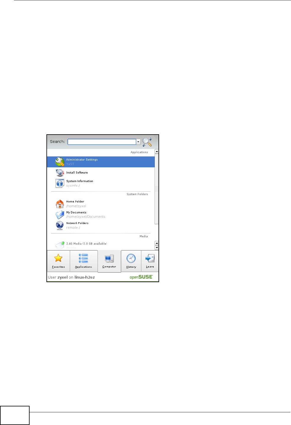
1Click K Menu > Computer > Administrator Settings (YaST).
Figure 100 openSUSE 10.3: K Menu > Computer Menu
Appendix B Setting Up Your Computer’s IP Address
User’s Guide 213
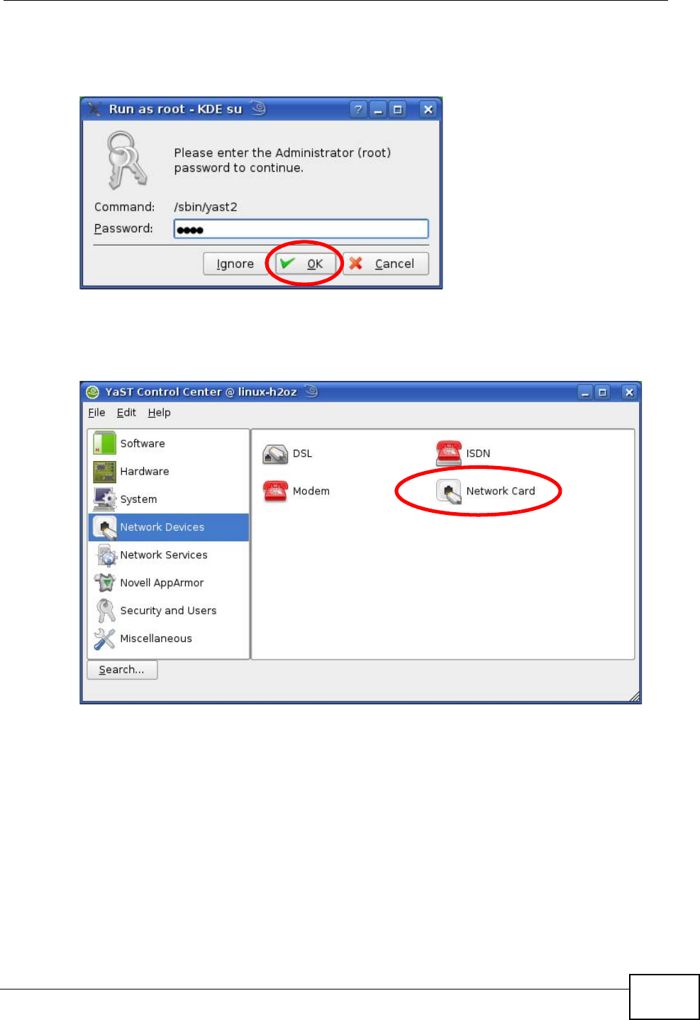
2When the Run as Root - KDE su dialog opens, enter the admin password and
click OK.
Figure 101 openSUSE 10.3: K Menu > Computer Menu
3When the YaST Control Center window opens, select Network Devices and
then click the Network Card icon.
Figure 102 openSUSE 10.3: YaST Control Center
Appendix B Setting Up Your Computer’s IP Address
User’s Guide
214
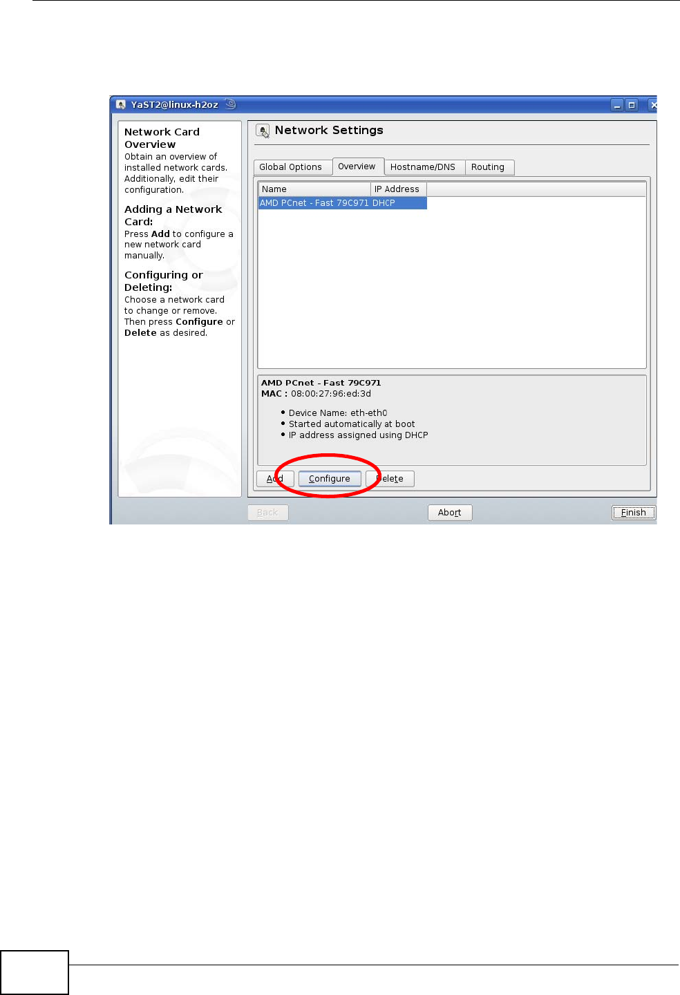
4When the Network Settings window opens, click the Overview tab, select the
appropriate connection Name from the list, and then click the Configure button.
Figure 103 openSUSE 10.3: Network Settings
Appendix B Setting Up Your Computer’s IP Address
User’s Guide 215
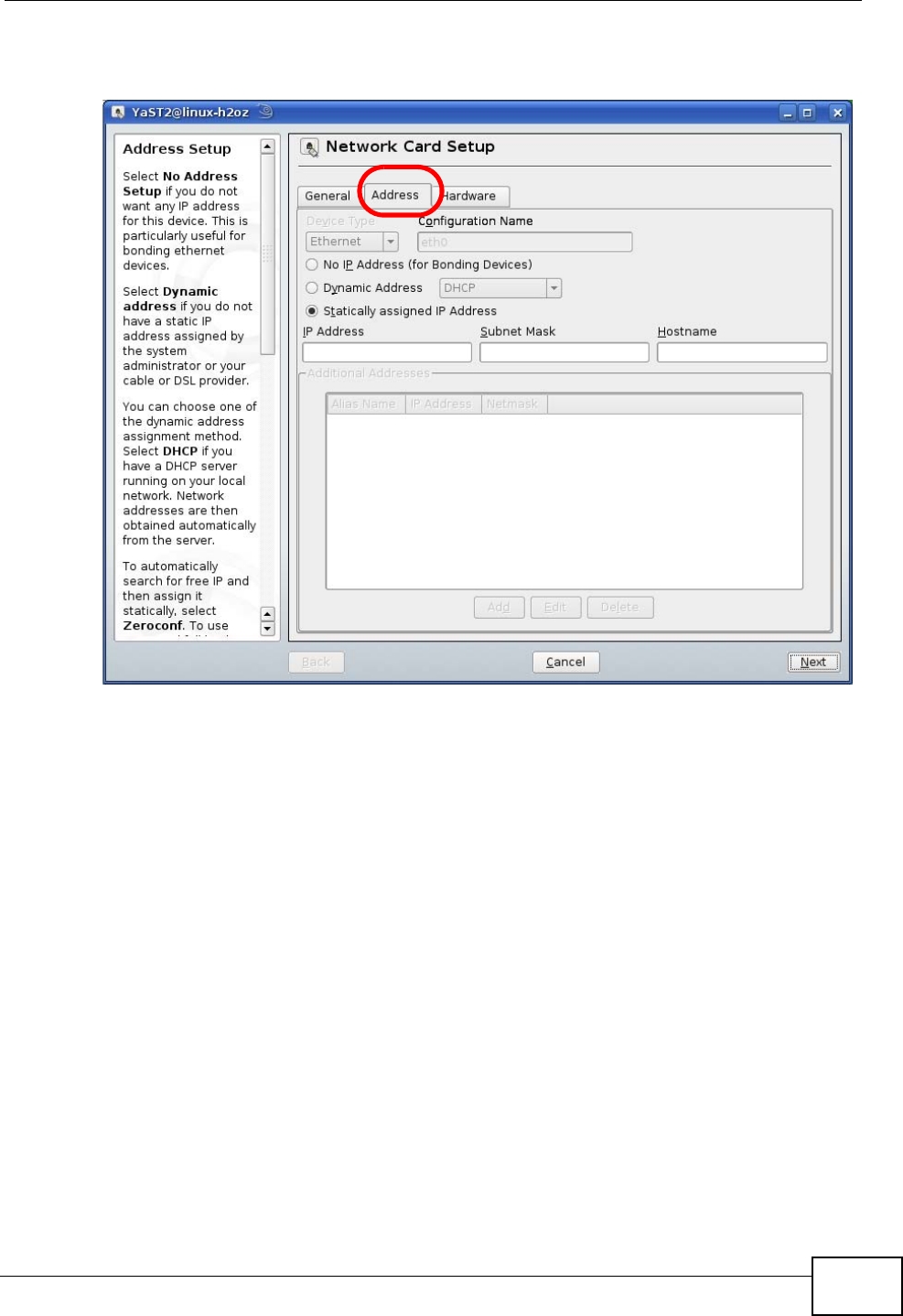
5When the Network Card Setup window opens, click the Address tab
Figure 104 openSUSE 10.3: Network Card Setup
6Select Dynamic Address (DHCP) if you have a dynamic IP address.
Select Statically assigned IP Address if you have a static IP address. Fill in the
IP address, Subnet mask, and Hostname fields.
7Click Next to save the changes and close the Network Card Setup window.
Appendix B Setting Up Your Computer’s IP Address
User’s Guide
216
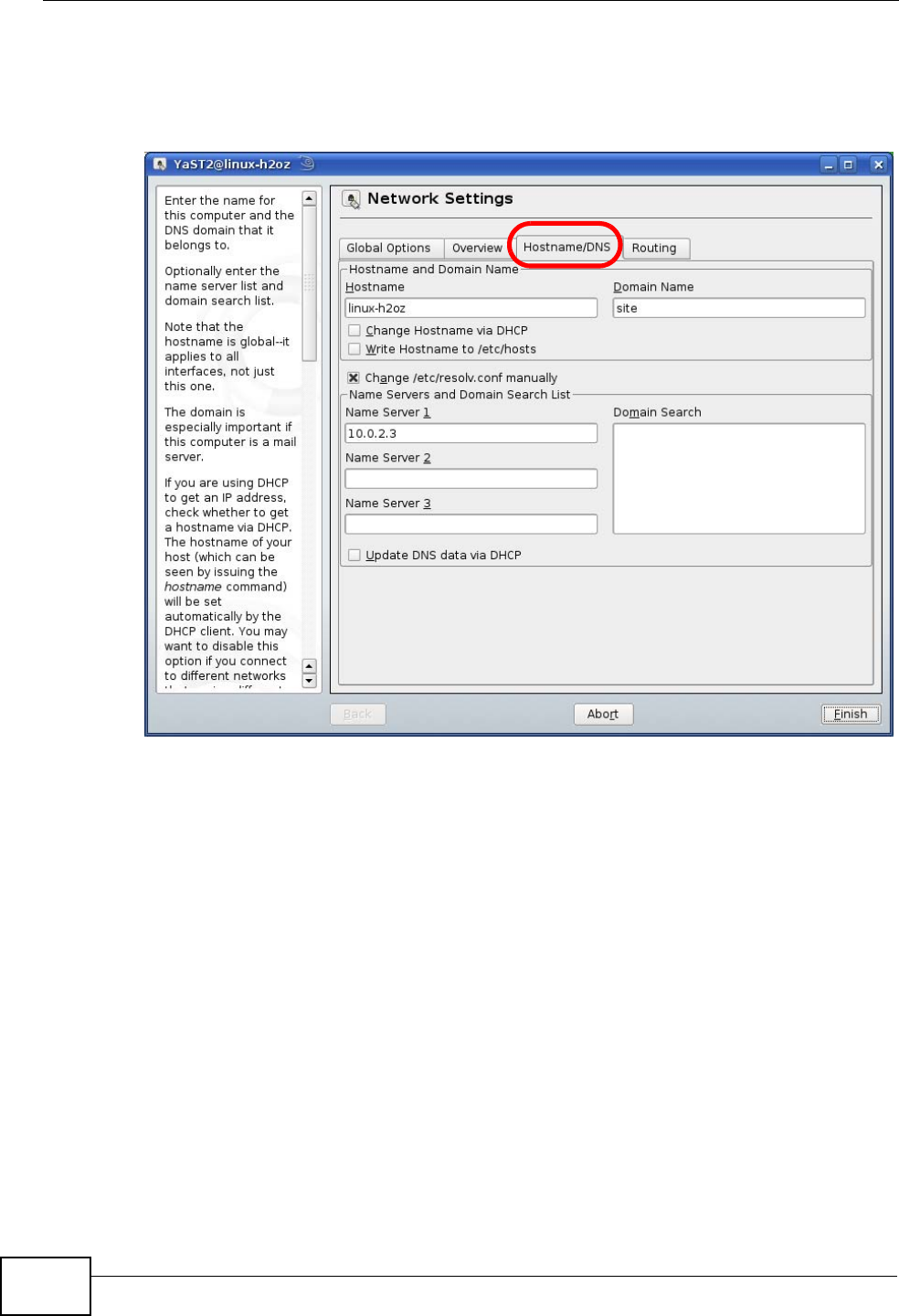
8If you know your DNS server IP address(es), click the Hostname/DNS tab in
Network Settings and then enter the DNS server information in the fields
provided.
Figure 105 openSUSE 10.3: Network Settings
9Click Finish to save your settings and close the window.
Appendix B Setting Up Your Computer’s IP Address
User’s Guide 217
Verifying Settings
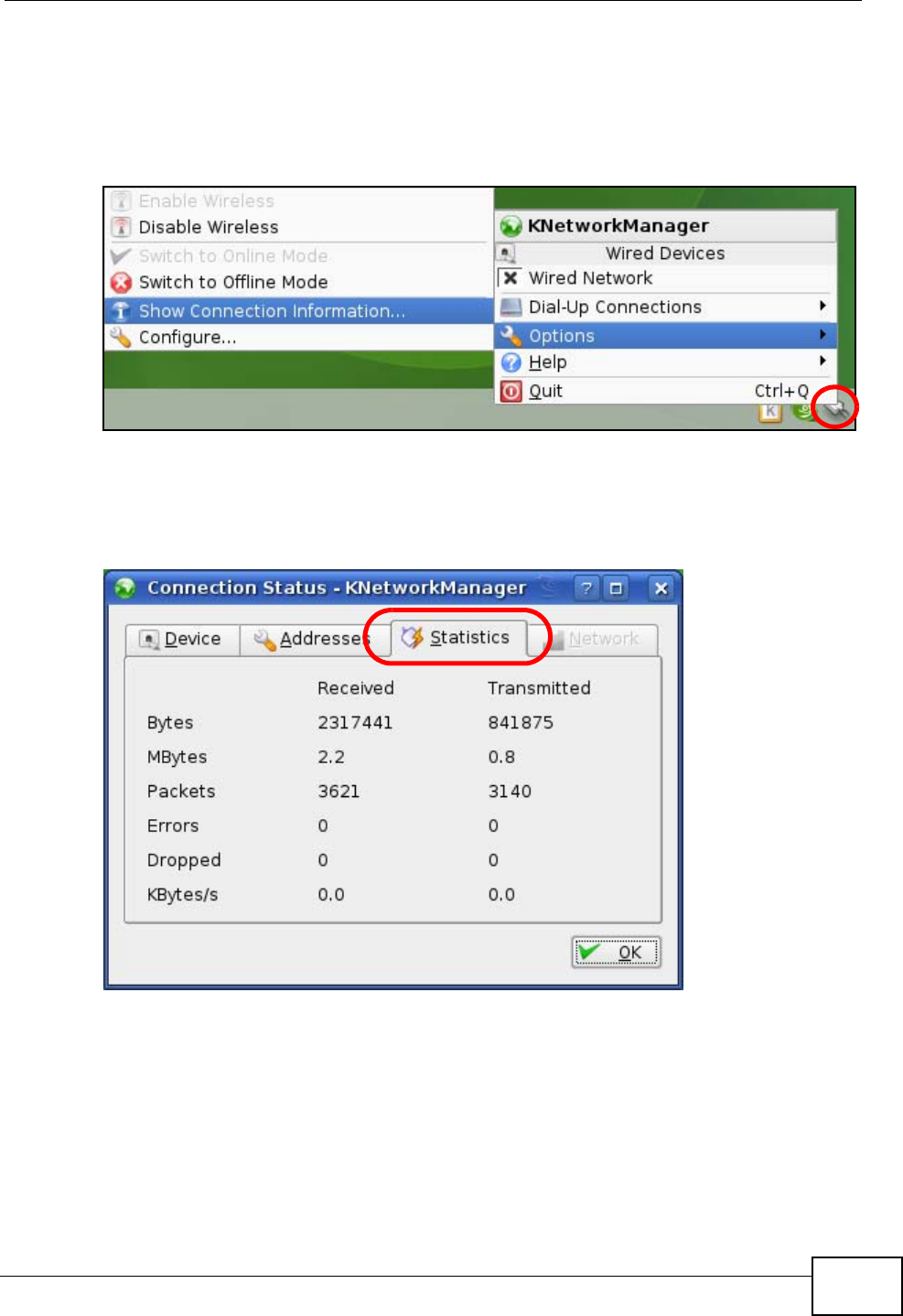
Click the KNetwork Manager icon on the Task bar to check your TCP/IP
properties. From the Options sub-menu, select Show Connection Information.
Figure 106 openSUSE 10.3: KNetwork Manager
When the Connection Status - KNetwork Manager window opens, click the
Statistics tab to see if your connection is working properly.
Figure 107 openSUSE: Connection Status - KNetwork Manager

Appendix B Setting Up Your Computer’s IP Address
User’s Guide
218
User’s Guide 219
APPENDIX C
Pop-up Windows, JavaScripts
and Java Permissions
In order to use the web configurator you need to allow:
• Web browser pop-up windows from your device.
• JavaScripts (enabled by default).
• Java permissions (enabled by default).
Note: Internet Explorer 6 screens are used here. Screens for other Internet Explorer
versions may vary.
Internet Explorer Pop-up Blockers
You may have to disable pop-up blocking to log into your device.
Either disable pop-up blocking (enabled by default in Windows XP SP (Service
Pack) 2) or allow pop-up blocking and create an exception for your device’s IP
address.
Disable Pop-up Blockers
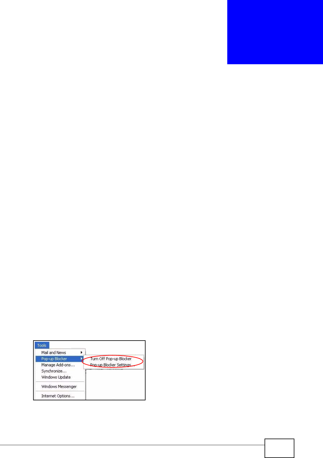
1In Internet Explorer, select Tools, Pop-up Blocker and then select Turn Off
Pop-up Blocker.
Figure 108 Pop-up Blocker
You can also check if pop-up blocking is disabled in the Pop-up Blocker section in
the Privacy tab.
Appendix C Pop-up Windows, JavaScripts and Java Permissions
User’s Guide
220
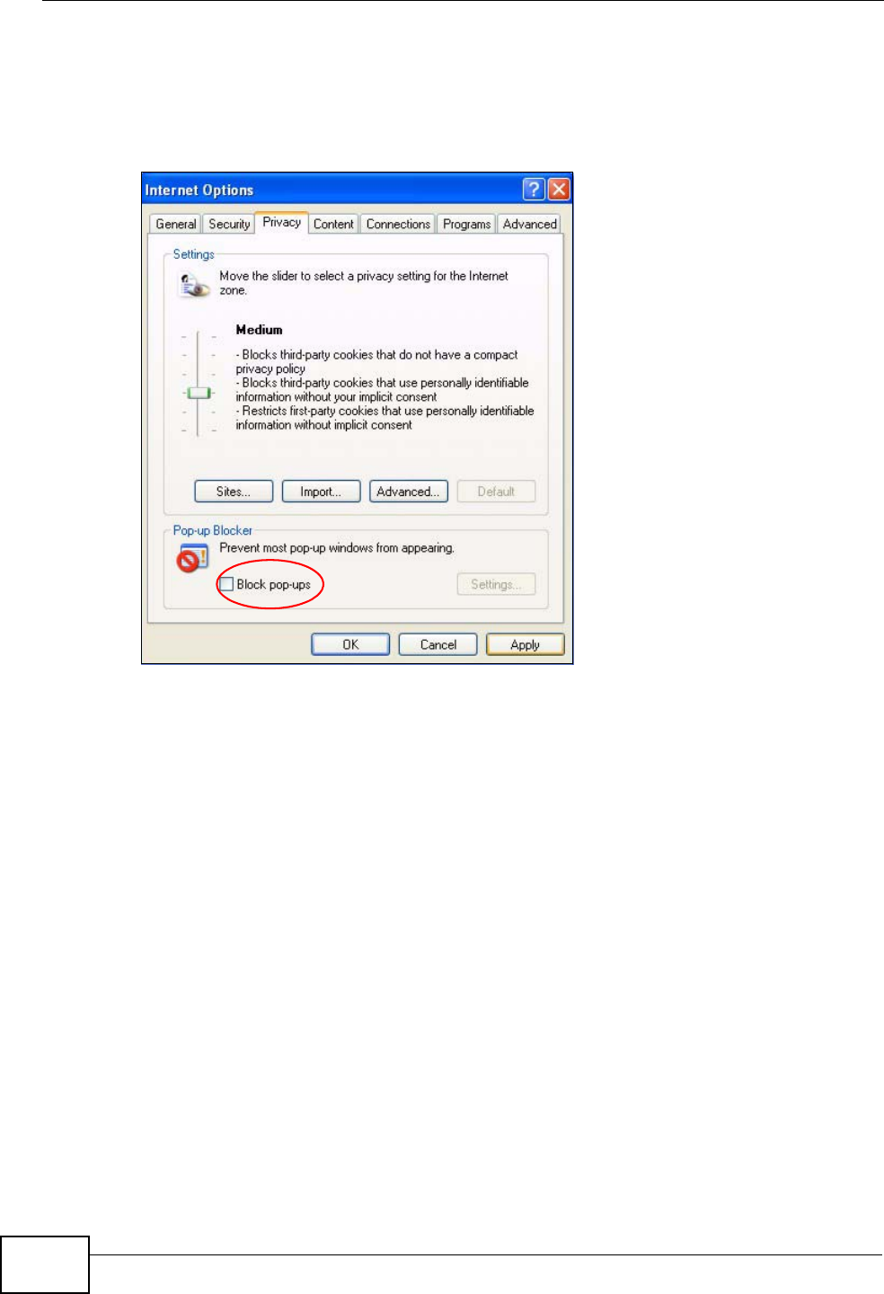
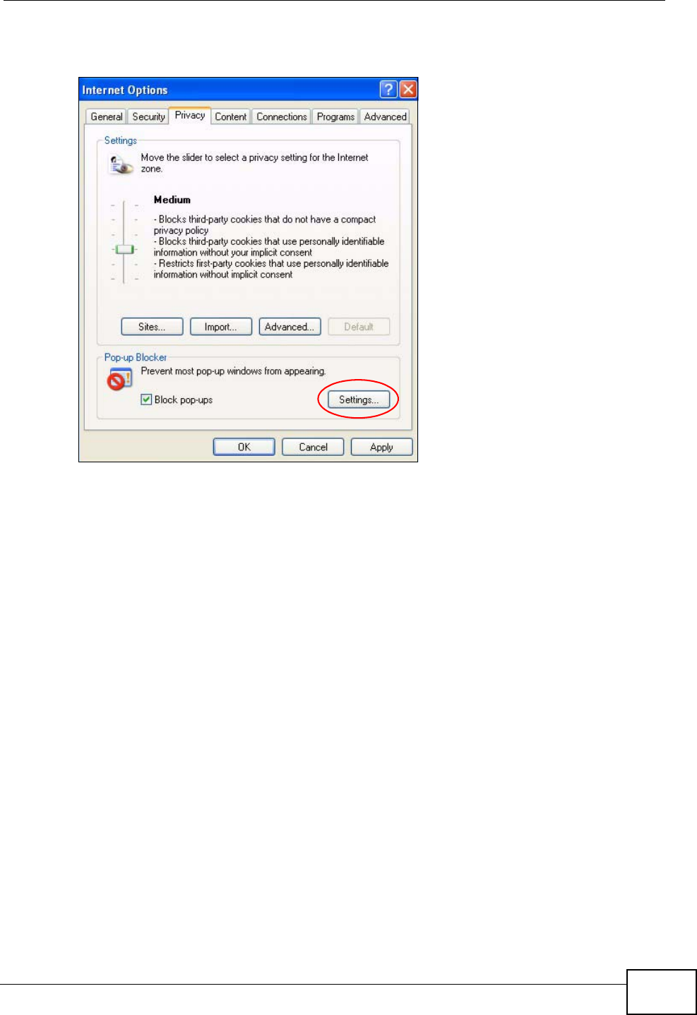
1In Internet Explorer, select Tools, Internet Options, Privacy.
2Clear the Block pop-ups check box in the Pop-up Blocker section of the screen.
This disables any web pop-up blockers you may have enabled.
Figure 109 Internet Options: Privacy
3Click Apply to save this setting.
Enable Pop-up Blockers with Exceptions
Alternatively, if you only want to allow pop-up windows from your device, see the
following steps.
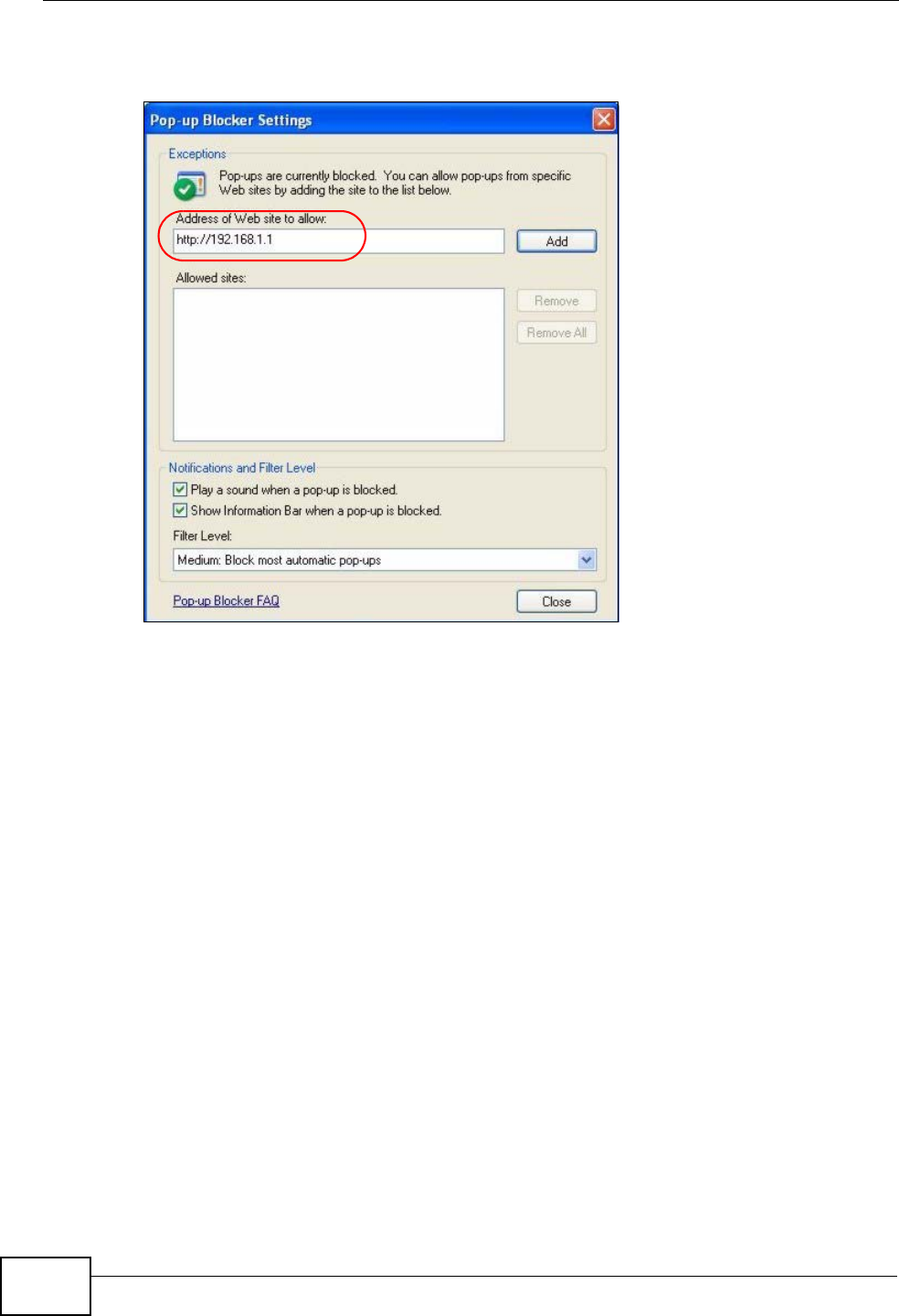
1In Internet Explorer, select Tools, Internet Options and then the Privacy tab.
Appendix C Pop-up Windows, JavaScripts and Java Permissions
User’s Guide 221
2Select Settings…to open the Pop-up Blocker Settings screen.
Figure 110 Internet Options: Privacy
3Type the IP address of your device (the web page that you do not want to have
blocked) with the prefix “http://”. For example, http://192.168.167.1.
Appendix C Pop-up Windows, JavaScripts and Java Permissions
User’s Guide
222
4Click Add to move the IP address to the list of Allowed sites.
Figure 111 Pop-up Blocker Settings
5Click Close to return to the Privacy screen.
6Click Apply to save this setting.
JavaScripts
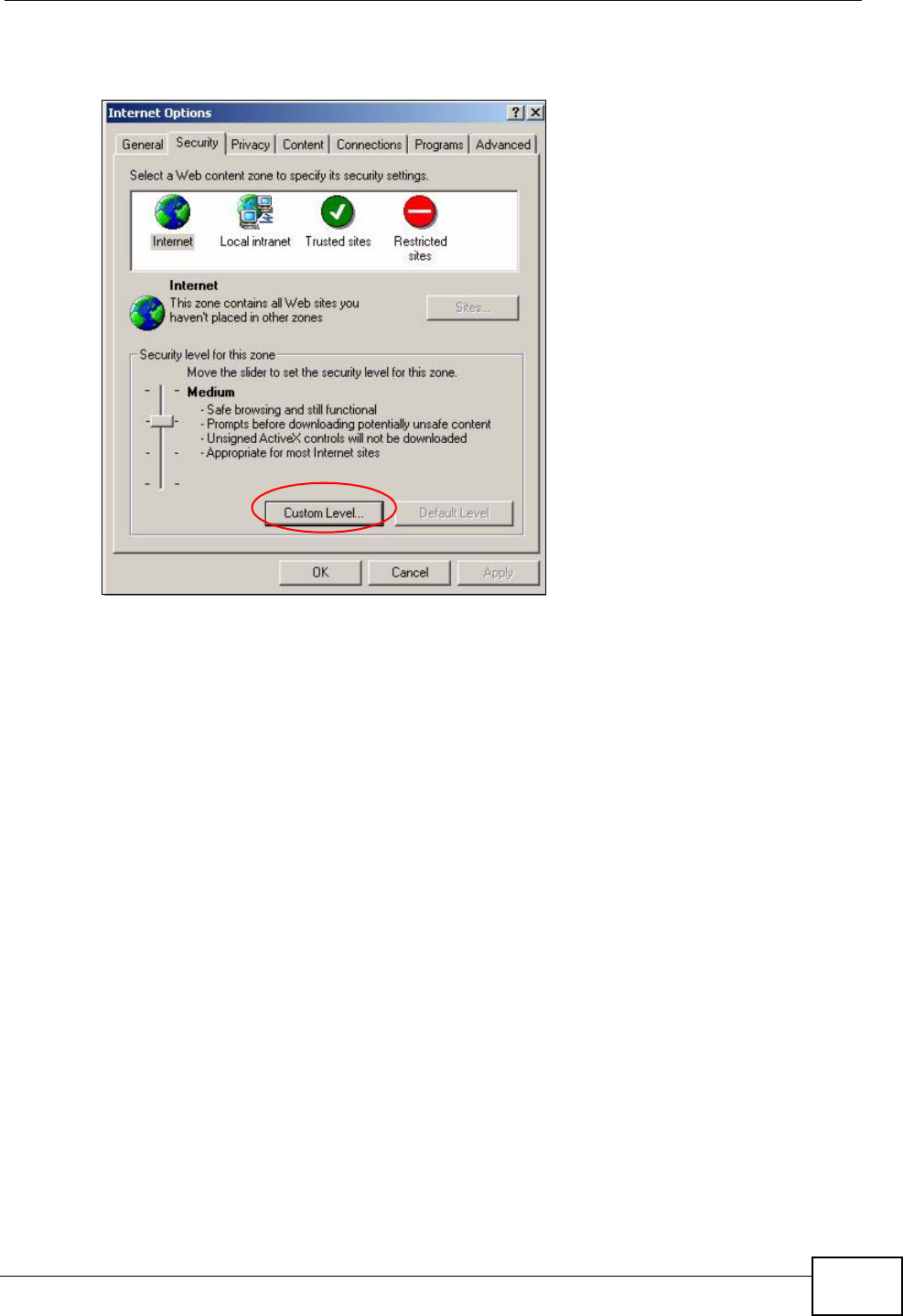
If pages of the web configurator do not display properly in Internet Explorer, check
that JavaScripts are allowed.
Appendix C Pop-up Windows, JavaScripts and Java Permissions
User’s Guide 223
1In Internet Explorer, click Tools, Internet Options and then the Security tab.
Figure 112 Internet Options: Security
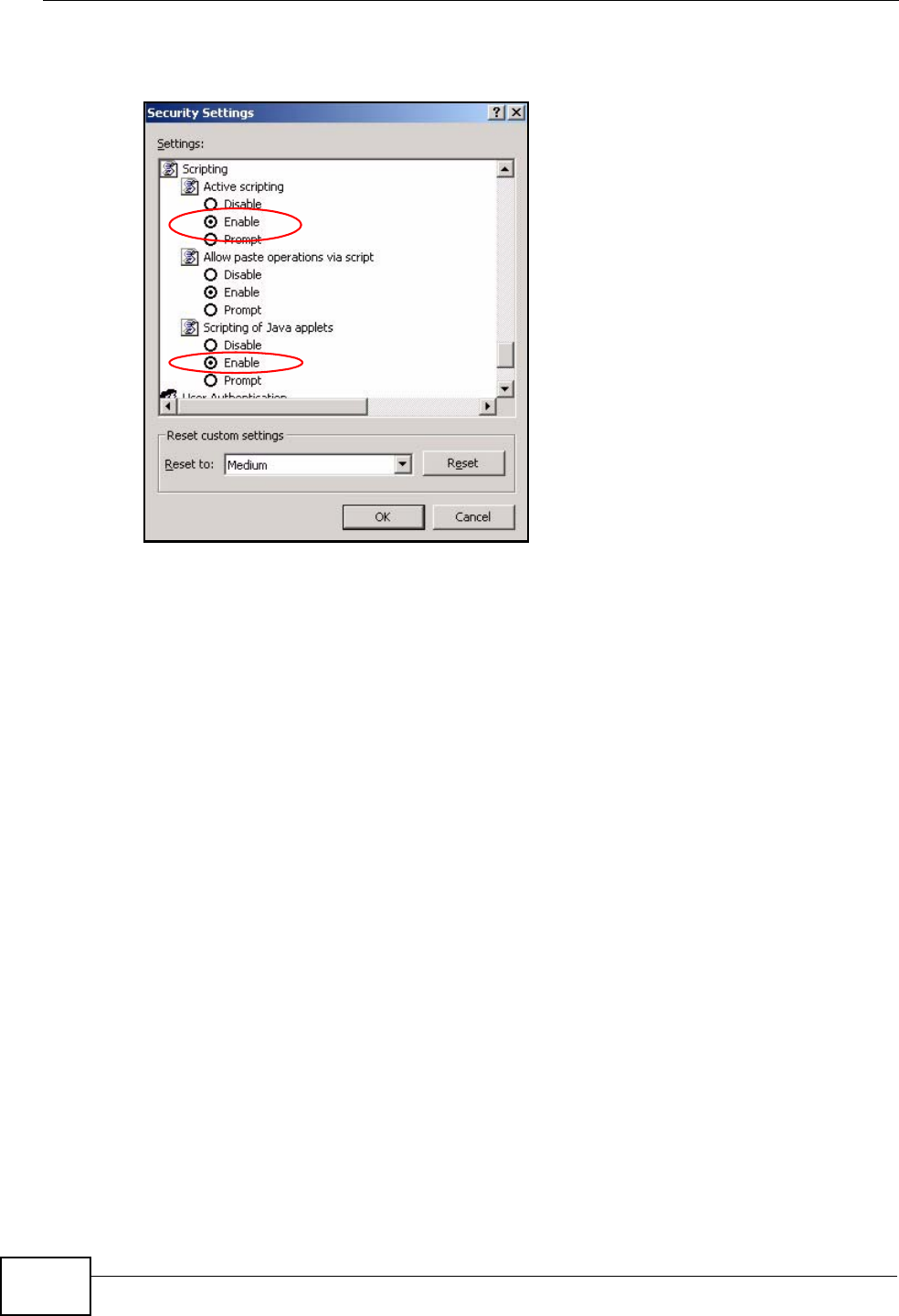
2Click the Custom Level... button.
3Scroll down to Scripting.
4Under Active scripting make sure that Enable is selected (the default).
5Under Scripting of Java applets make sure that Enable is selected (the
default).
Appendix C Pop-up Windows, JavaScripts and Java Permissions
User’s Guide
224
6Click OK to close the window.
Figure 113 Security Settings - Java Scripting
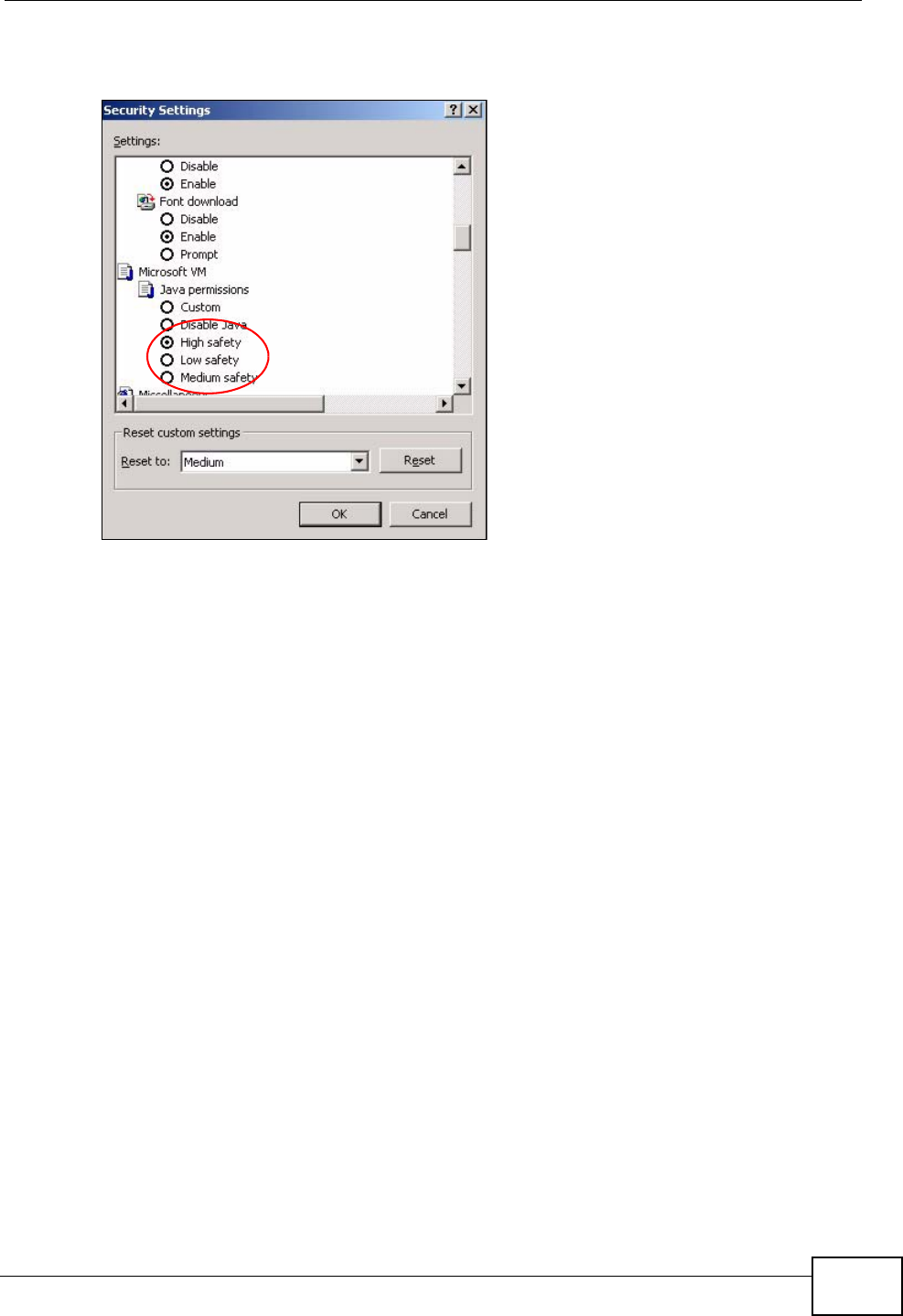
Java Permissions
1From Internet Explorer, click Tools, Internet Options and then the Security
tab.
2Click the Custom Level... button.
3Scroll down to Microsoft VM.
4Under Java permissions make sure that a safety level is selected.
Appendix C Pop-up Windows, JavaScripts and Java Permissions
User’s Guide 225
5Click OK to close the window.
Figure 114 Security Settings - Java
JAVA (Sun)
1From Internet Explorer, click Tools, Internet Options and then the Advanced
tab.
2Make sure that Use Java 2 for <applet> under Java (Sun) is selected.
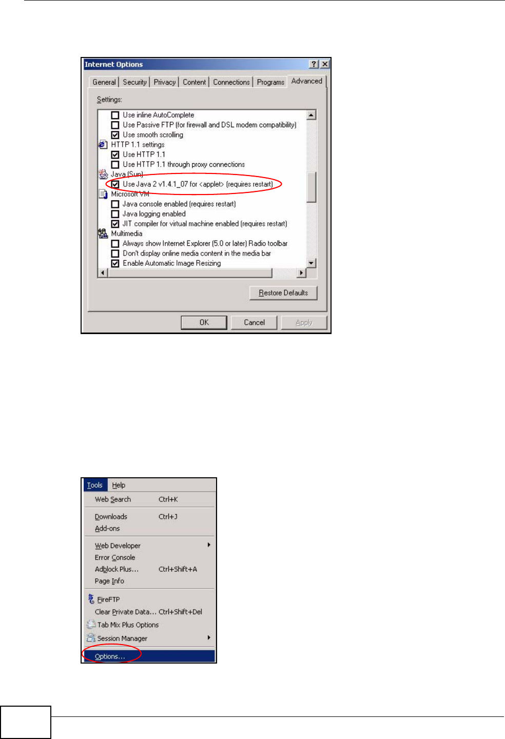
Appendix C Pop-up Windows, JavaScripts and Java Permissions
User’s Guide
226
3Click OK to close the window.
Figure 115 Java (Sun)
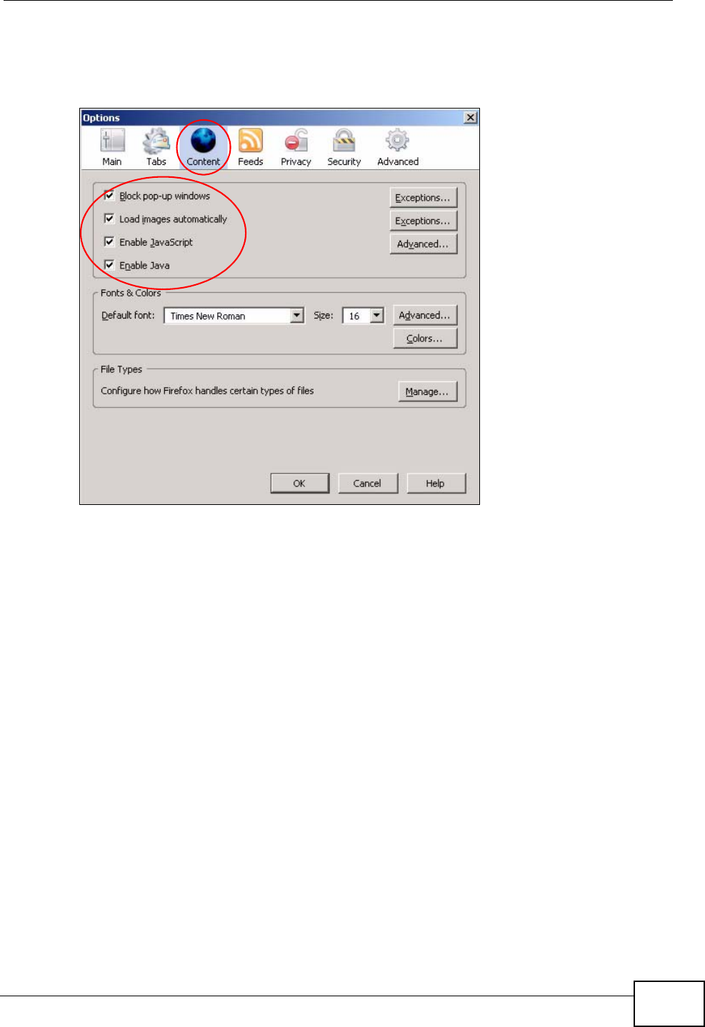
Mozilla Firefox
Mozilla Firefox 2.0 screens are used here. Screens for other versions may vary.
You can enable Java, Javascripts and pop-ups in one screen. Click Tools, then
click Options in the screen that appears.
Figure 116 Mozilla Firefox: TOOLS > Options
Appendix C Pop-up Windows, JavaScripts and Java Permissions
User’s Guide 227
Click Content.to show the screen below. Select the check boxes as shown in the
following screen.
Figure 117 Mozilla Firefox Content Security

Appendix C Pop-up Windows, JavaScripts and Java Permissions
User’s Guide
228

User’s Guide 229
APPENDIX D
IP Addresses and Subnetting
This appendix introduces IP addresses and subnet masks.
IP addresses identify individual devices on a network. Every networking device
(including computers, servers, routers, printers, etc.) needs an IP address to
communicate across the network. These networking devices are also known as
hosts.
Subnet masks determine the maximum number of possible hosts on a network.
You can also use subnet masks to divide one network into multiple sub-networks.
Introduction to IP Addresses
One part of the IP address is the network number, and the other part is the host
ID. In the same way that houses on a street share a common street name, the
hosts on a network share a common network number. Similarly, as each house
has its own house number, each host on the network has its own unique
identifying number - the host ID. Routers use the network number to send packets
to the correct network, while the host ID determines to which host on the network
the packets are delivered.
Structure
An IP address is made up of four parts, written in dotted decimal notation (for
example, 192.168.100.1). Each of these four parts is known as an octet. An octet
is an eight-digit binary number (for example 11000000, which is 192 in decimal
notation).
Therefore, each octet has a possible range of 00000000 to 11111111 in binary, or
0 to 255 in decimal.
Appendix D IP Addresses and Subnetting
User’s Guide
230
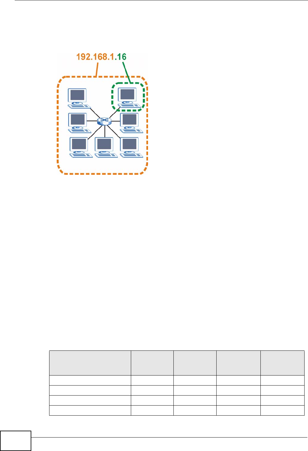
The following figure shows an example IP address in which the first three octets
(192.168.1) are the network number, and the fourth octet (16) is the host ID.
Figure 118 Network Number and Host ID
How much of the IP address is the network number and how much is the host ID
varies according to the subnet mask.
Subnet Masks
A subnet mask is used to determine which bits are part of the network number,
and which bits are part of the host ID (using a logical AND operation). The term
“subnet” is short for “sub-network”.
A subnet mask has 32 bits. If a bit in the subnet mask is a “1” then the
corresponding bit in the IP address is part of the network number. If a bit in the
subnet mask is “0” then the corresponding bit in the IP address is part of the host
ID.
The following example shows a subnet mask identifying the network number (in
bold text) and host ID of an IP address (192.168.1.2 in decimal).
Table 71 IP Address Network Number and Host ID Example
1ST OCTET:
(192)
2ND OCTET:
(168)
3RD OCTET:
(1)
4TH OCTET
(2)
IP Address (Binary) 11000000 10101000 00000001 00000010
Subnet Mask (Binary) 11111111 11111111 11111111 00000000
Network Number 11000000 10101000 00000001
Host ID 00000010
Appendix D IP Addresses and Subnetting
User’s Guide 231
By convention, subnet masks always consist of a continuous sequence of ones
beginning from the leftmost bit of the mask, followed by a continuous sequence of
zeros, for a total number of 32 bits.
Subnet masks can be referred to by the size of the network number part (the bits
with a “1” value). For example, an “8-bit mask” means that the first 8 bits of the
mask are ones and the remaining 24 bits are zeroes.
Subnet masks are expressed in dotted decimal notation just like IP addresses. The
following examples show the binary and decimal notation for 8-bit, 16-bit, 24-bit
and 29-bit subnet masks.
Network Size
The size of the network number determines the maximum number of possible
hosts you can have on your network. The larger the number of network number
bits, the smaller the number of remaining host ID bits.
An IP address with host IDs of all zeros is the IP address of the network
(192.168.1.0 with a 24-bit subnet mask, for example). An IP address with host
IDs of all ones is the broadcast address for that network (192.168.1.255 with a
24-bit subnet mask, for example).
As these two IP addresses cannot be used for individual hosts, calculate the
maximum number of possible hosts in a network as follows:
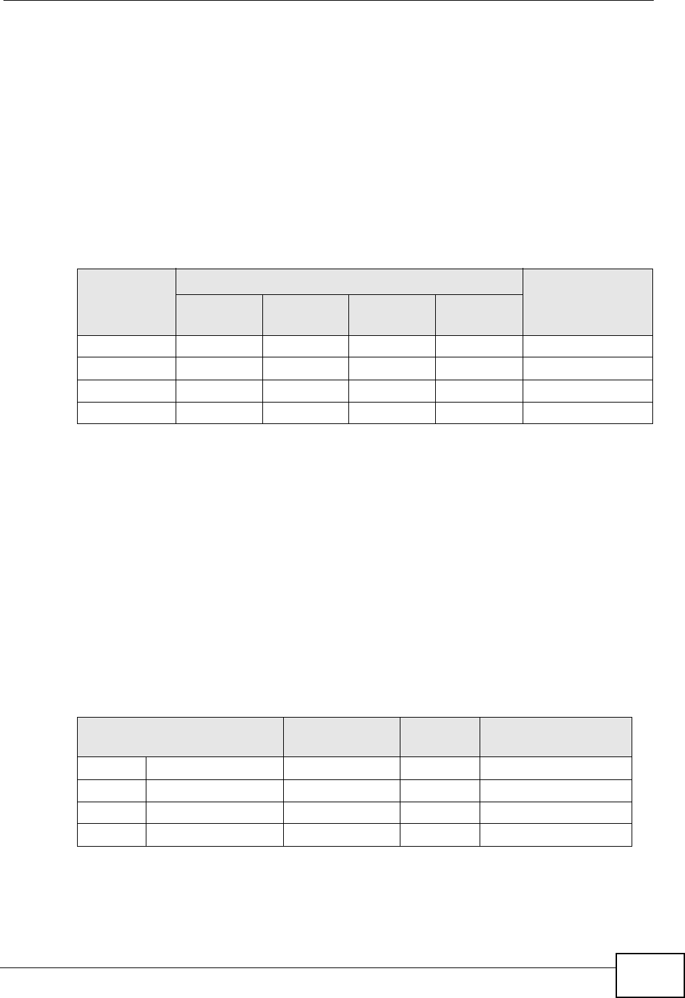
Table 72 Subnet Masks
BINARY
DECIMAL
1ST
OCTET 2ND
OCTET 3RD
OCTET 4TH
OCTET
8-bit mask 11111111 00000000 00000000 00000000 255.0.0.0
16-bit mask 11111111 11111111 00000000 00000000 255.255.0.0
24-bit mask 11111111 11111111 11111111 00000000 255.255.255.0
29-bit mask 11111111 11111111 11111111 11111000 255.255.255.248
Table 73 Maximum Host Numbers
SUBNET MASK HOST ID SIZE MAXIMUM NUMBER
OF HOSTS
8 bits 255.0.0.0 24 bits 224 – 2 16777214
16 bits 255.255.0.0 16 bits 216 – 2 65534
24 bits 255.255.255.0 8 bits 28 – 2 254
29 bits 255.255.255.248 3 bits 23 – 2 6