ZyXEL Communications NBG318S Wireless Ethernet Adapter User Manual NBG 318 User s Guide
ZyXEL Communications Corporation Wireless Ethernet Adapter NBG 318 User s Guide
Contents
- 1. User Manual 1
- 2. Users Manual 2
- 3. Users Manual 3
- 4. Users Manual 4
Users Manual 2
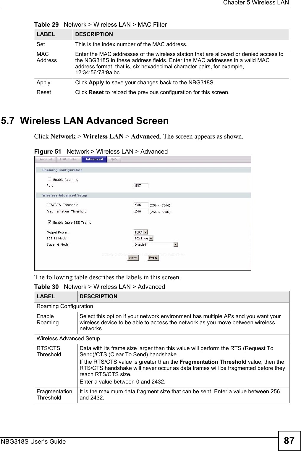
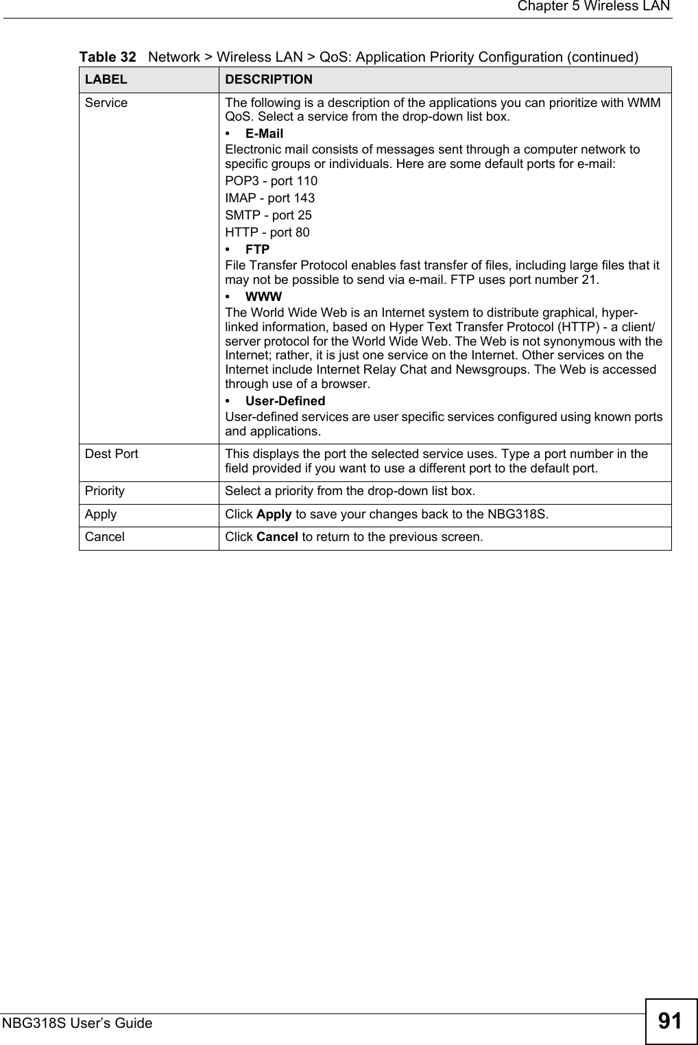
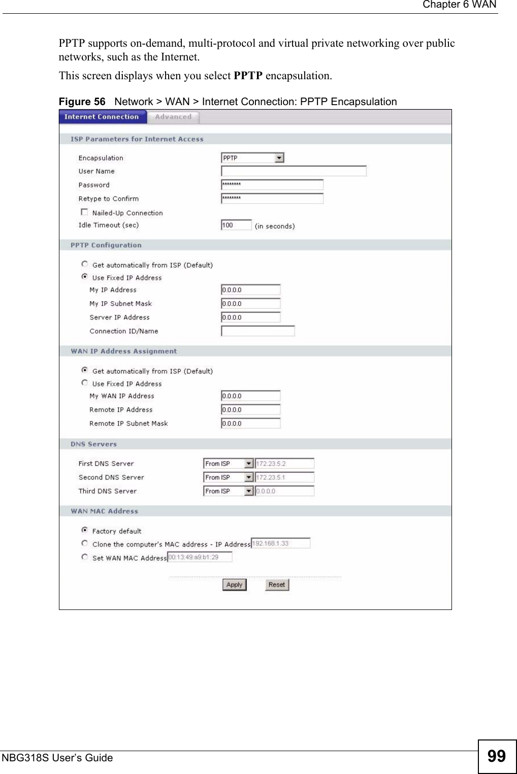
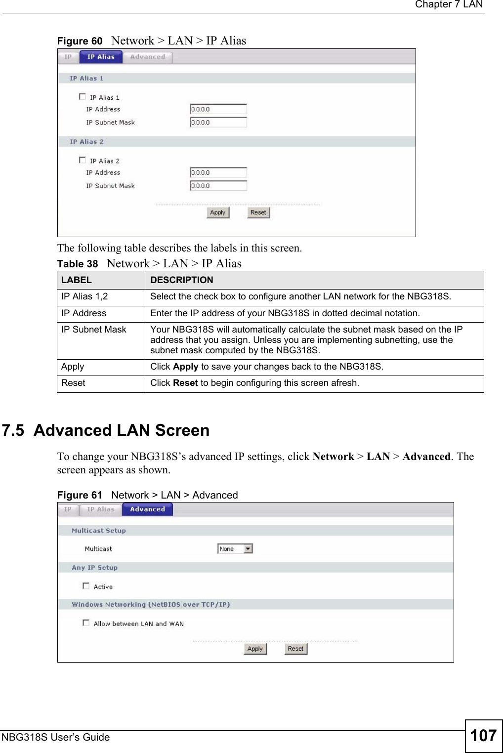
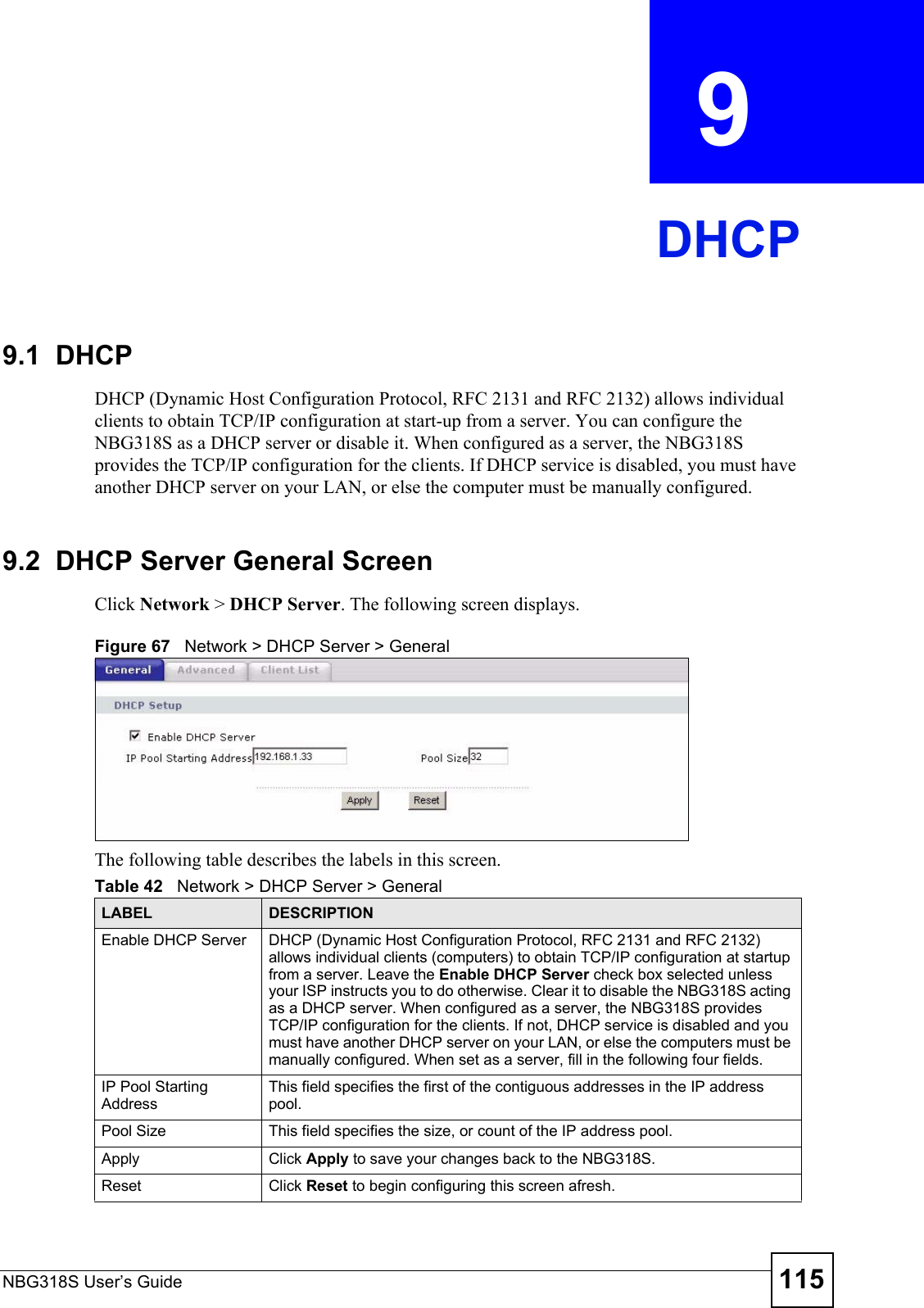
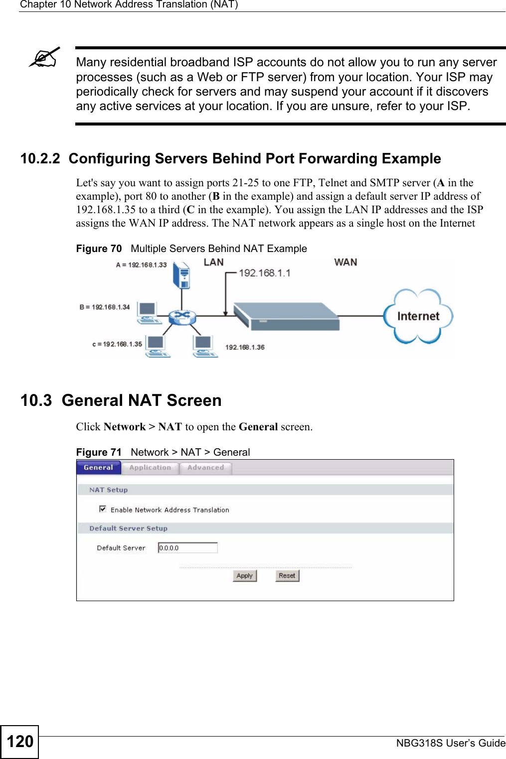


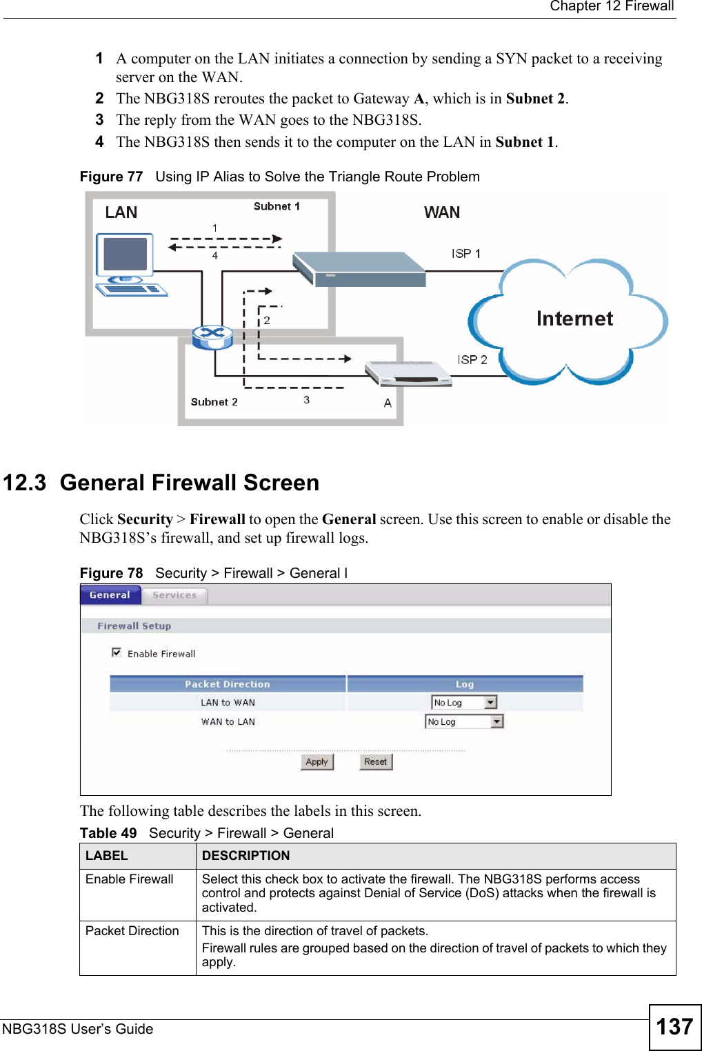
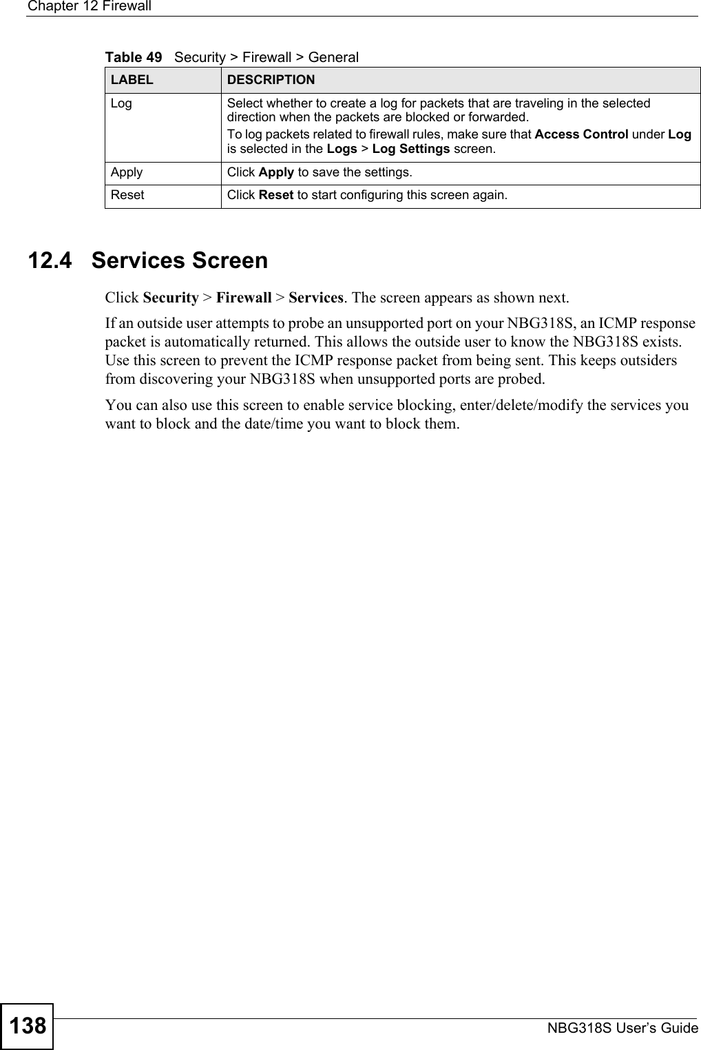
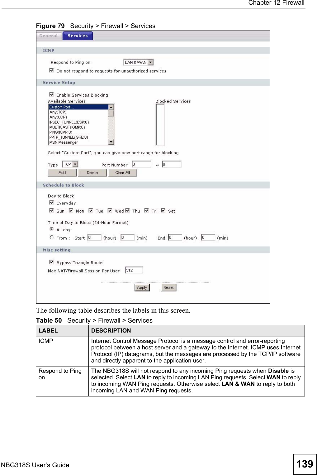
![Chapter 12 FirewallNBG318S User’s Guide140Do not respond to requests for unauthorized servicesSelect this option to prevent hackers from finding the NBG318S by probing for unused ports. If you select this option, the NBG318S will not respond to port request(s) for unused ports, thus leaving the unused ports and the NBG318S unseen. By default this option is not selected and the NBG318S will reply with an ICMP Port Unreachable packet for a port probe on its unused UDP ports, and a TCP Reset packet for a port probe on its unused TCP ports. Note that the probing packets must first traverse the NBG318S's firewall mechanism before reaching this anti-probing mechanism. Therefore if the firewall mechanism blocks a probing packet, the NBG318S reacts based on the firewall policy, which by default, is to send a TCP reset packet for a blocked TCP packet. You can use the command "sys firewall tcprst rst [on|off]" to change this policy. When the firewall mechanism blocks a UDP packet, it drops the packet without sending a response packet.Service SetupEnable Services BlockingSelect this check box to enable this feature.Available ServicesThis is a list of pre-defined services (ports) you may prohibit your LAN computers from using. Select the port you want to block using the drop-down list and click Add to add the port to the Blocked Services field.Blocked Services This is a list of services (ports) that will be inaccessible to computers on your LAN once you enable service blocking. Custom Port A custom port is a service that is not available in the pre-defined Available Services list and you must define using the next two fields.Type Choose the IP port (TCP or UDP) that defines your customized port from the drop down list box.Port Number Enter the port number range that defines the service. For example, if you want to define the Gnutella service, then select TCP type and enter a port range from 6345 to 6349.Add Select a service from the Available Services drop-down list and then click Add to add a service to the Blocked ServicesDelete Select a service from the Blocked Services list and then click Delete to remove this service from the list.Clear All Click Clear All to empty the Blocked Services.Schedule to BlockDay to Block: Select a check box to configure which days of the week (or everyday) you want service blocking to be active. Time of Day to Block (24-Hour Format)Select the time of day you want service blocking to take effect. Configure blocking to take effect all day by selecting All Day. You can also configure specific times by selecting From and entering the start time in the Start (hour) and Start (min) fields and the end time in the End (hour) and End (min) fields. Enter times in 24-hour format, for example, "3:00pm" should be entered as "15:00".Misc settingBypass Triangle RouteSelect this check box to have the NBG318S firewall ignore the use of triangle route topology on the network. Max NAT/Firewall Session Per UserType a number ranging from 1 to 2048 to limit the number of NAT/firewall sessions that a host can create.Apply Click Apply to save the settings. Reset Click Reset to start configuring this screen again. Table 50 Security > Firewall > ServicesLABEL DESCRIPTION](https://usermanual.wiki/ZyXEL-Communications/NBG318S.Users-Manual-2/User-Guide-812921-Page-60.png)
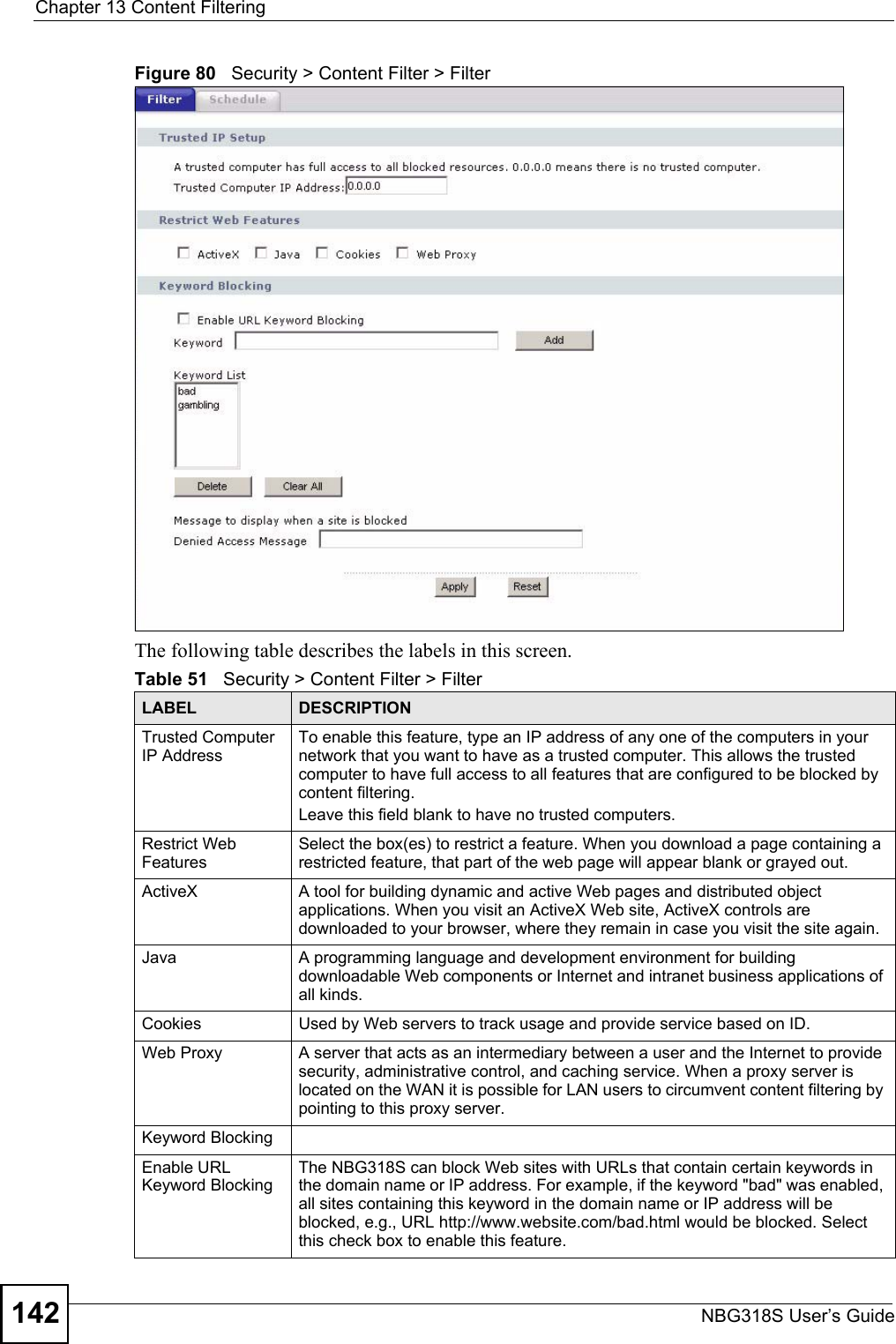
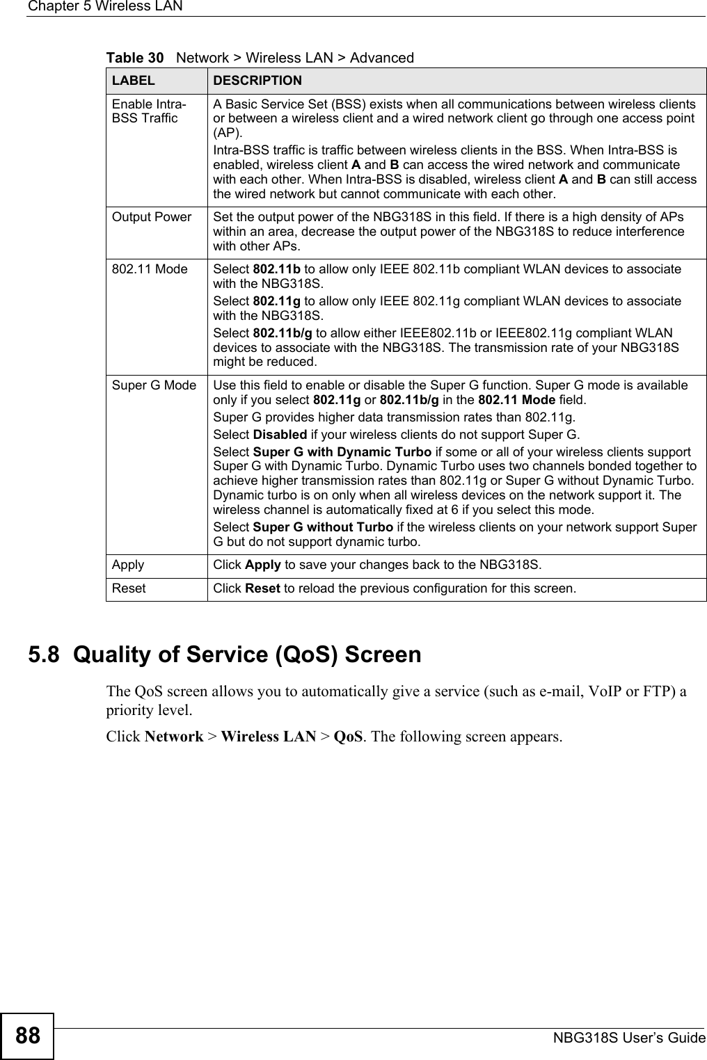
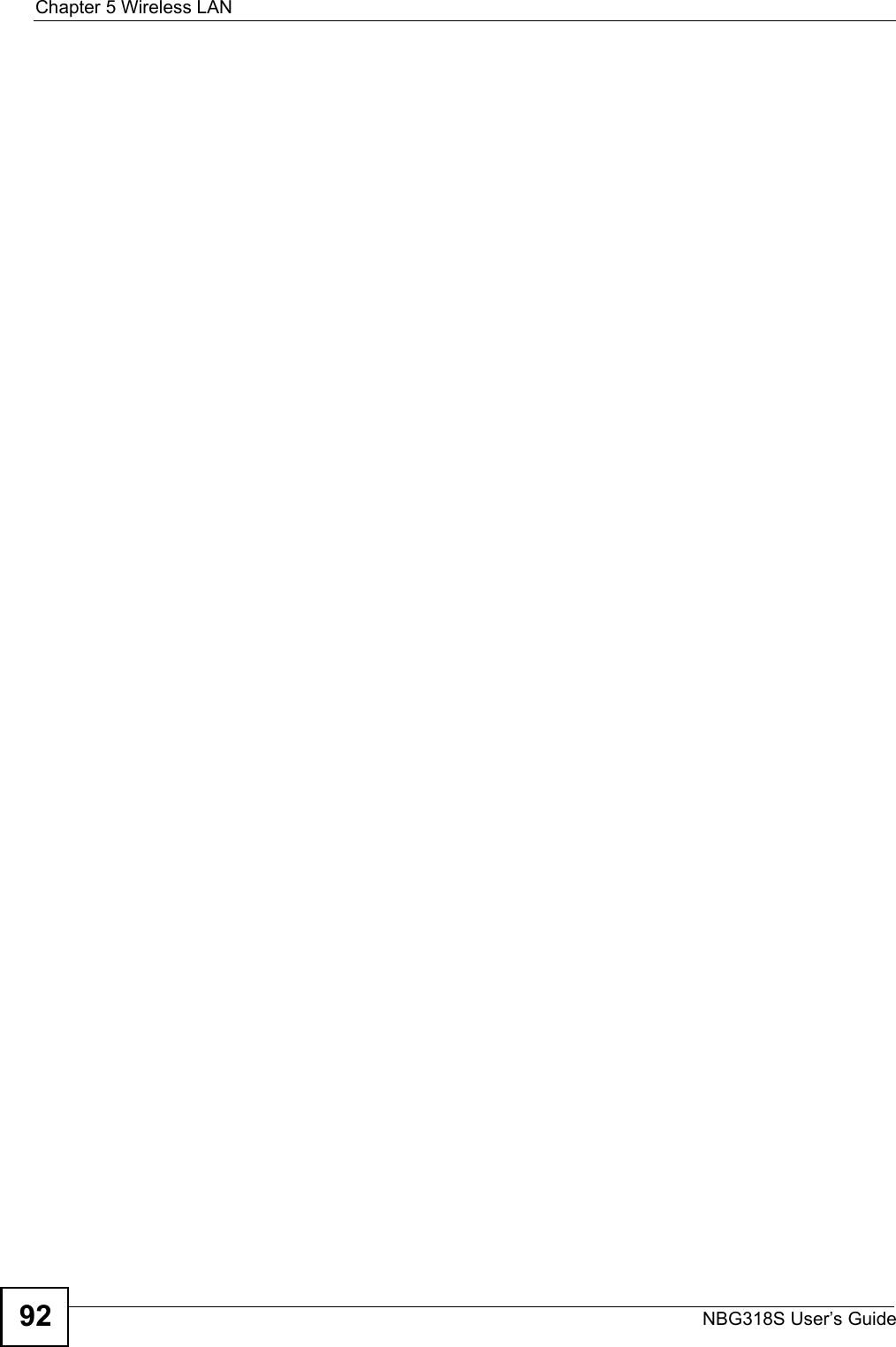
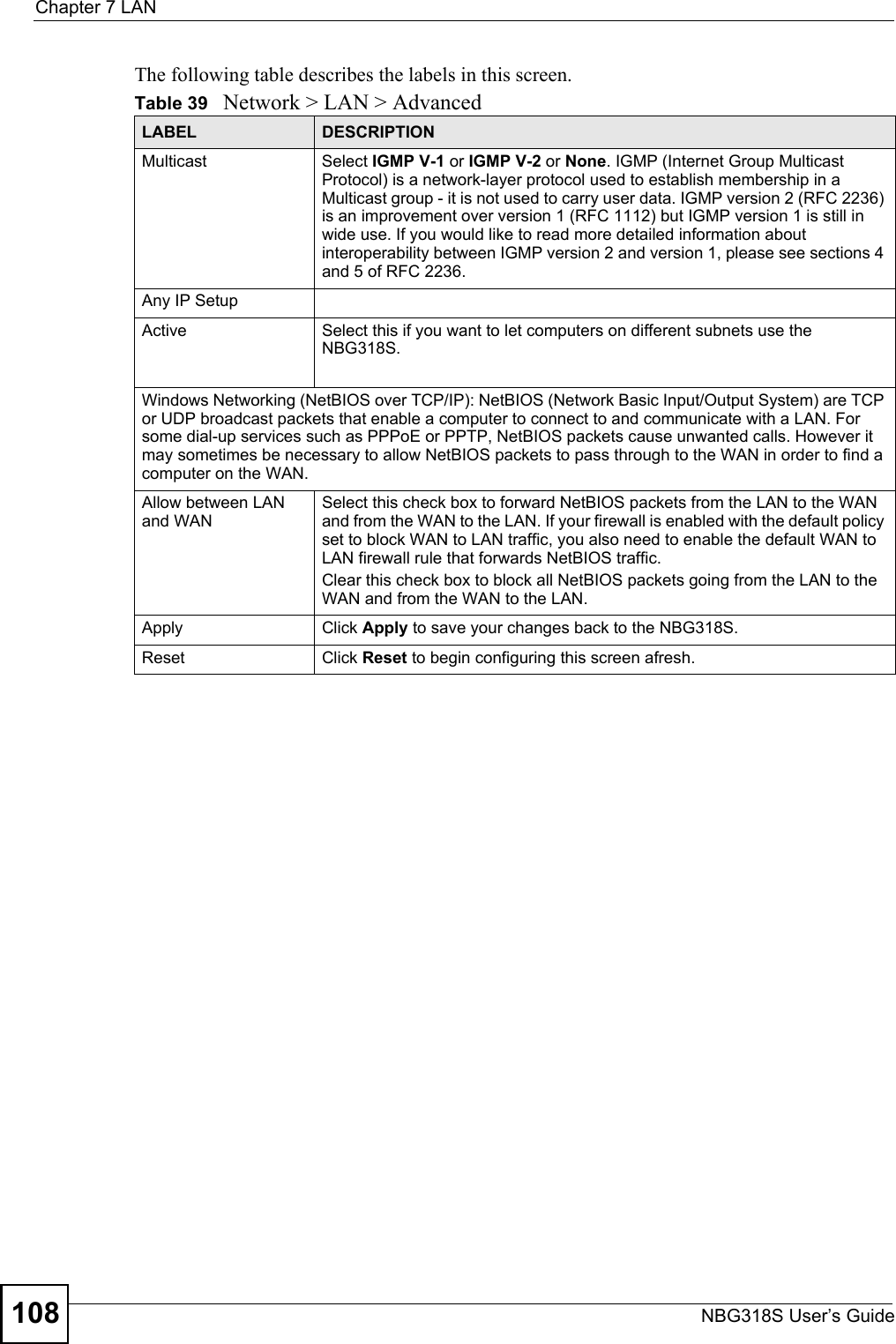
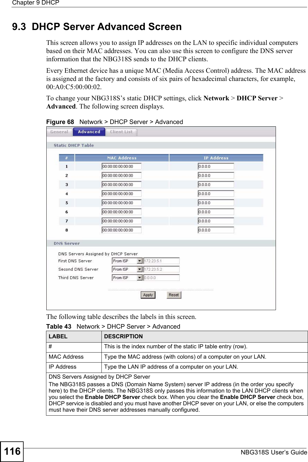
![Chapter 13 Content FilteringNBG318S User’s Guide14413.6 Customizing Keyword Blocking URL CheckingYou can use commands to set how much of a website’s URL the content filter is to check for keyword blocking. See the appendices for information on how to access and use the command interpreter.13.6.1 Domain Name or IP Address URL CheckingBy default, the NBG318S checks the URL’s domain name or IP address when performing keyword blocking.This means that the NBG318S checks the characters that come before the first slash in the URL.For example, with the URL www.zyxel.com.tw/news/pressroom.php, content filtering only searches for keywords within www.zyxel.com.tw.13.6.2 Full Path URL CheckingFull path URL checking has the NBG318S check the characters that come before the last slash in the URL.For example, with the URL www.zyxel.com.tw/news/pressroom.php, full path URL checking searches for keywords within www.zyxel.com.tw/news/.Use the ip urlfilter customize actionFlags 6 [disable | enable] command to extend (or not extend) the keyword blocking search to include the URL's full path.13.6.3 File Name URL CheckingFilename URL checking has the NBG318S check all of the characters in the URL.For example, filename URL checking searches for keywords within the URL www.zyxel.com.tw/news/pressroom.php.Use the ip urlfilter customize actionFlags 8 [disable | enable] command to extend (or not extend) the keyword blocking search to include the URL's complete filename.Apply Click Apply to save your customized settings and exit this screen.Reset Click Reset to begin configuring this screen afreshTable 52 Security > Content Filter > ScheduleLABEL DESCRIPTION](https://usermanual.wiki/ZyXEL-Communications/NBG318S.Users-Manual-2/User-Guide-812921-Page-64.png)