ZyXEL Communications NBG318S Wireless Ethernet Adapter User Manual NBG 318 User s Guide
ZyXEL Communications Corporation Wireless Ethernet Adapter NBG 318 User s Guide
Contents
- 1. User Manual 1
- 2. Users Manual 2
- 3. Users Manual 3
- 4. Users Manual 4
Users Manual 2
Chapter 5 Wireless LAN
NBG318S User’s Guide 81
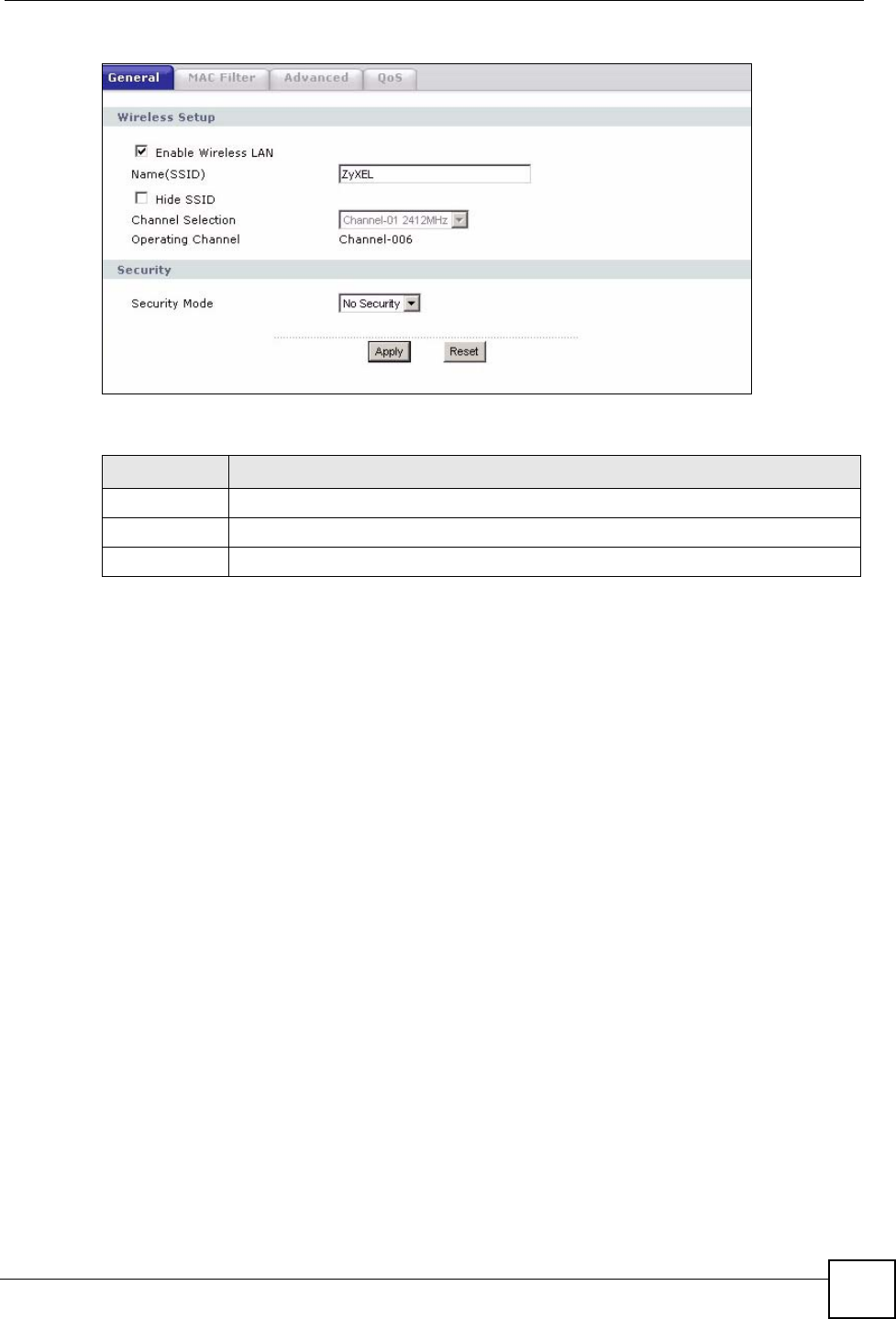
Figure 46 Network > Wireless LAN > General: No Security
The following table describes the labels in this screen.
5.5.2 WEP Encryption
WEP encryption scrambles the data transmitted between the wireless stations and the access
points to keep network communications private. It encrypts unicast and multicast
communications in a network. Both the wireless stations and the access points must use the
same WEP key.
Your NBG318S allows you to configure up to four 64-bit or 128-bit WEP keys but only one
key can be enabled at any one time.
In order to configure and enable WEP encryption; click Network > Wireless LAN to display
the General screen. Select Static WEP from the Security Mode list.
Table 25 Wireless No Security
LABEL DESCRIPTION
Security Mode Choose No Security from the drop-down list box.
Apply Click Apply to save your changes back to the NBG318S.
Reset Click Reset to reload the previous configuration for this screen.
Chapter 5 Wireless LAN
NBG318S User’s Guide
82
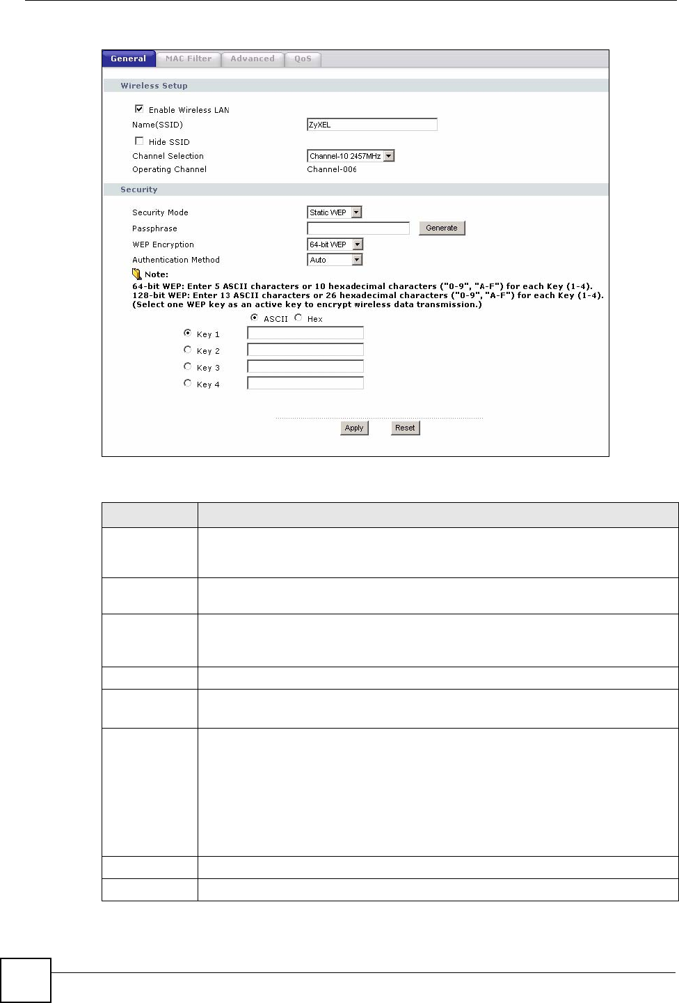
Figure 47 Network > Wireless LAN > General: Static WEP
The following table describes the wireless LAN security labels in this screen.
Table 26 Network > Wireless LAN > General: Static WEP
LABEL DESCRIPTION
Passphrase Enter a passphrase (password phrase) of up to 32 printable characters and click
Generate. The NBG318S automatically generates four different WEP keys and
displays them in the Key fields below.
WEP
Encryption
Select 64-bit WEP or 128-bit WEP to enable data encryption.
Authentication
Method
This field is activated when you select 64-bit WEP or 128-bit WEP in the WEP
Encryption field.
Select Auto, Open System or Shared Key from the drop-down list box.
ASCII Select this option in order to enter ASCII characters as WEP key.
Hex Select this option in order to enter hexadecimal characters as a WEP key.
The preceding "0x", that identifies a hexadecimal key, is entered automatically.
Key 1 to Key 4 The WEP keys are used to encrypt data. Both the NBG318S and the wireless
stations must use the same WEP key for data transmission.
If you chose 64-bit WEP, then enter any 5 ASCII characters or 10 hexadecimal
characters ("0-9", "A-F").
If you chose 128-bit WEP, then enter 13 ASCII characters or 26 hexadecimal
characters ("0-9", "A-F").
You must configure at least one key, only one key can be activated at any one time.
The default key is key 1.
Apply Click Apply to save your changes back to the NBG318S.
Reset Click Reset to reload the previous configuration for this screen.
Chapter 5 Wireless LAN
NBG318S User’s Guide 83
5.5.3 WPA-PSK/WPA2-PSK
Click Network > Wireless LAN to display the General screen. Select WPA-PSK or WPA2-
PSK from the Security Mode list.
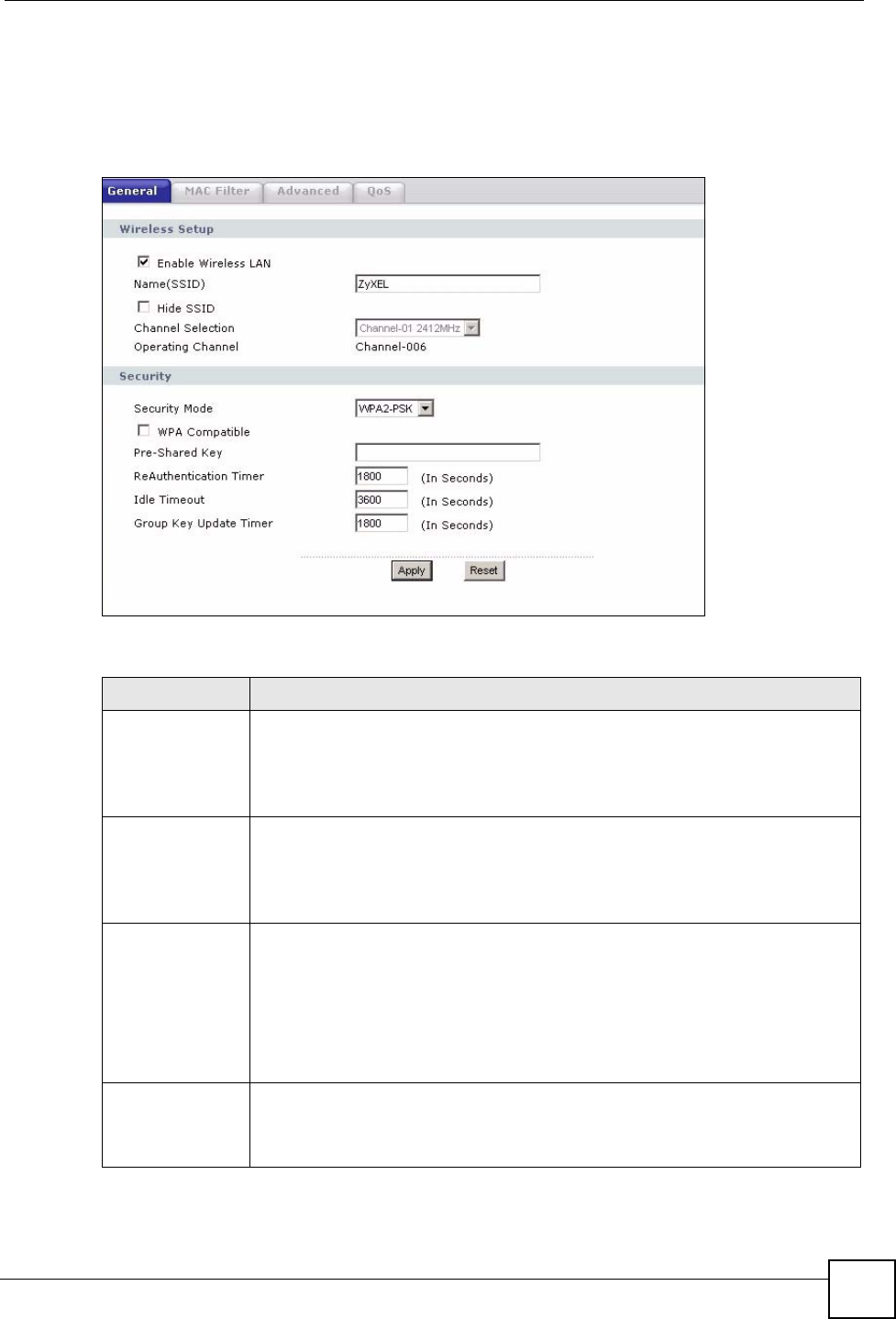
Figure 48 Network > Wireless LAN > General: WPA-PSK/WPA2-PSK
The following table describes the labels in this screen.
Table 27 Network > Wireless LAN > General: WPA-PSK/WPA2-PSK
LABEL DESCRIPTION
WPA Compatible This check box is available only when you select WPA2-PSK or WPA2 in the
Security Mode field.
Select the check box to have both WPA2 and WPA wireless clients be able to
communicate with the NBG318S even when the NBG318S is using WPA2-PSK or
WPA2.
Pre-Shared Key The encryption mechanisms used for WPA/WPA2 and WPA-PSK/WPA2-PSK
are the same. The only difference between the two is that WPA-PSK/WPA2-PSK
uses a simple common password, instead of user-specific credentials.
Type a pre-shared key from 8 to 63 case-sensitive ASCII characters (including
spaces and symbols).
ReAuthentication
Timer (in
seconds)
Specify how often wireless stations have to resend usernames and passwords in
order to stay connected. Enter a time interval between 10 and 9999 seconds. The
default time interval is 1800 seconds (30 minutes).
Note: If wireless station authentication is done using a RADIUS
server, the reauthentication timer on the RADIUS server has
priority.
Idle Timeout The NBG318S automatically disconnects a wireless station from the wired
network after a period of inactivity. The wireless station needs to enter the
username and password again before access to the wired network is allowed. The
default time interval is 3600 seconds (or 1 hour).
Chapter 5 Wireless LAN
NBG318S User’s Guide
84
5.5.4 WPA/WPA2
Click Network > Wireless LAN to display the General screen. Select WPA or WPA2 from
the Security Mode list.
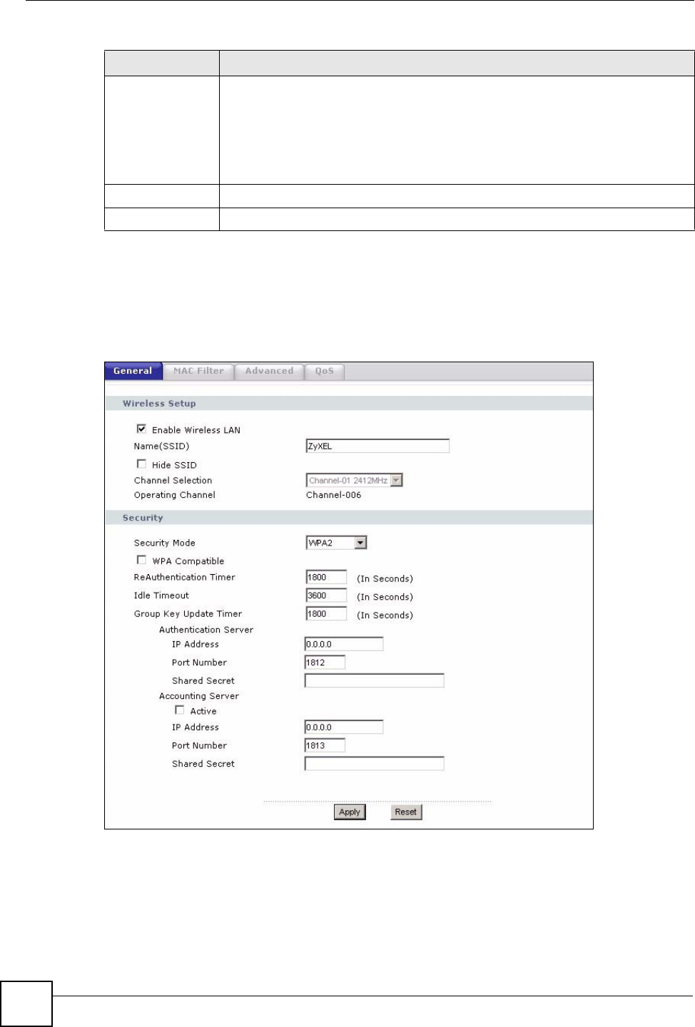
Figure 49 Network > Wireless LAN > General: WPA/WPA2
Group Key
Update Timer
The Group Key Update Timer is the rate at which the AP (if using WPA-PSK/
WPA2-PSK key management) or RADIUS server (if using WPA/WPA2 key
management) sends a new group key out to all clients. The re-keying process is
the WPA/WPA2 equivalent of automatically changing the WEP key for an AP and
all stations in a WLAN on a periodic basis. Setting of the Group Key Update
Timer is also supported in WPA-PSK/WPA2-PSK mode. The default is 1800
seconds (30 minutes).
Apply Click Apply to save your changes back to the NBG318S.
Reset Click Reset to reload the previous configuration for this screen.
Table 27 Network > Wireless LAN > General: WPA-PSK/WPA2-PSK
LABEL DESCRIPTION

Chapter 5 Wireless LAN
NBG318S User’s Guide 85
The following table describes the labels in this screen.
Table 28 Network > Wireless LAN > General: WPA/WPA2
LABEL DESCRIPTION
WPA Compatible This check box is available only when you select WPA2-PSK or WPA2 in the
Security Mode field.
Select the check box to have both WPA2 and WPA wireless clients be able to
communicate with the NBG318S even when the NBG318S is using WPA2-PSK
or WPA2.
ReAuthentication
Timer (in seconds)
Specify how often wireless stations have to resend usernames and passwords in
order to stay connected. Enter a time interval between 10 and 9999 seconds.
The default time interval is 1800 seconds (30 minutes).
Note: If wireless station authentication is done using a RADIUS
server, the reauthentication timer on the RADIUS server
has priority.
Idle Timeout The NBG318S automatically disconnects a wireless station from the wired
network after a period of inactivity. The wireless station needs to enter the
username and password again before access to the wired network is allowed.
The default time interval is 3600 seconds (or 1 hour).
Group Key Update
Timer
The Group Key Update Timer is the rate at which the AP (if using WPA-PSK/
WPA2-PSK key management) or RADIUS server (if using WPA/WPA2 key
management) sends a new group key out to all clients. The re-keying process is
the WPA/WPA2 equivalent of automatically changing the WEP key for an AP
and all stations in a WLAN on a periodic basis. Setting of the Group Key Update
Timer is also supported in WPA-PSK/WPA2-PSK mode. The NBG318S default
is 1800 seconds (30 minutes).
Authentication Server
IP Address Enter the IP address of the external authentication server in dotted decimal
notation.
Port Number Enter the port number of the external authentication server. The default port
number is 1812.
You need not change this value unless your network administrator instructs you
to do so with additional information.
Shared Secret Enter a password (up to 31 alphanumeric characters) as the key to be shared
between the external authentication server and the NBG318S.
The key must be the same on the external authentication server and your
NBG318S. The key is not sent over the network.
Accounting Server
Active Select Yes from the drop down list box to enable user accounting through an
external authentication server.
IP Address Enter the IP address of the external accounting server in dotted decimal notation.
Port Number Enter the port number of the external accounting server. The default port number
is 1813.
You need not change this value unless your network administrator instructs you
to do so with additional information.
Shared Secret Enter a password (up to 31 alphanumeric characters) as the key to be shared
between the external accounting server and the NBG318S.
The key must be the same on the external accounting server and your
NBG318S. The key is not sent over the network.
Apply Click Apply to save your changes back to the NBG318S.
Reset Click Reset to reload the previous configuration for this screen.
Chapter 5 Wireless LAN
NBG318S User’s Guide
86
5.6 MAC Filter
The MAC filter screen allows you to configure the NBG318S to give exclusive access to up to
32 devices (Allow) or exclude up to 32 devices from accessing the NBG318S (Deny). Every
Ethernet device has a unique MAC (Media Access Control) address. The MAC address is
assigned at the factory and consists of six pairs of hexadecimal characters, for example,
00:A0:C5:00:00:02. You need to know the MAC address of the devices to configure this
screen.
To change your NBG318S’s MAC filter settings, click Network > Wireless LAN > MAC
Filter. The screen appears as shown.
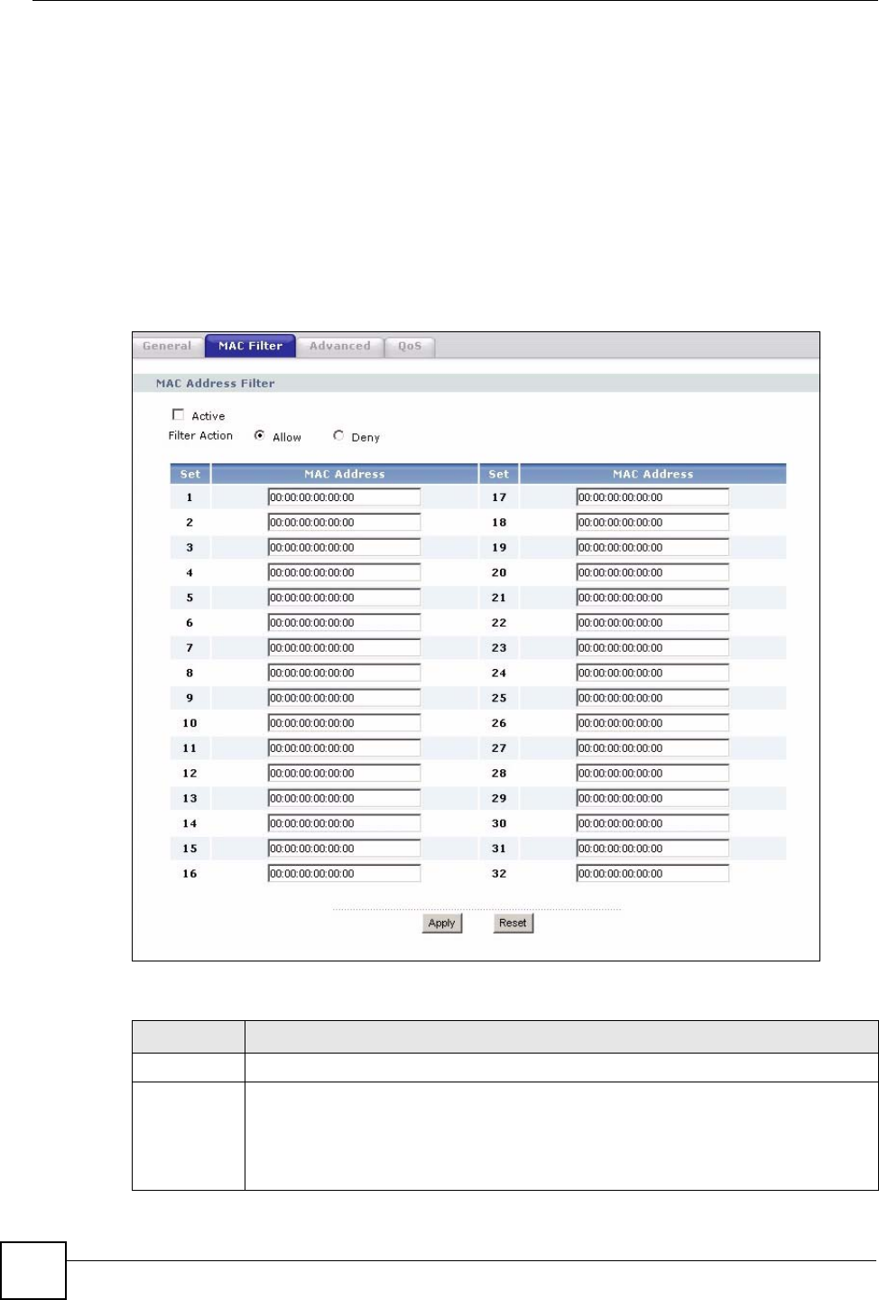
Figure 50 Network > Wireless LAN > MAC Filter
The following table describes the labels in this menu.
Table 29 Network > Wireless LAN > MAC Filter
LABEL DESCRIPTION
Active Select Yes from the drop down list box to enable MAC address filtering.
Filter Action Define the filter action for the list of MAC addresses in the MAC Address table.
Select Deny to block access to the NBG318S, MAC addresses not listed will be
allowed to access the NBG318S
Select Allow to permit access to the NBG318S, MAC addresses not listed will be
denied access to the NBG318S.
Chapter 5 Wireless LAN
NBG318S User’s Guide 87
5.7 Wireless LAN Advanced Screen
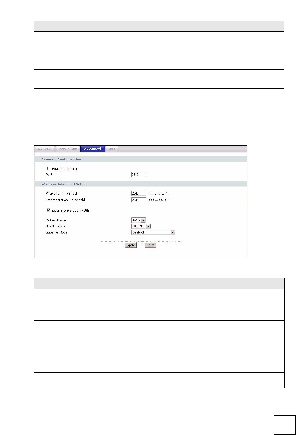
Click Network > Wireless LAN > Advanced. The screen appears as shown.
Figure 51 Network > Wireless LAN > Advanced
The following table describes the labels in this screen.
Set This is the index number of the MAC address.
MAC
Address
Enter the MAC addresses of the wireless station that are allowed or denied access to
the NBG318S in these address fields. Enter the MAC addresses in a valid MAC
address format, that is, six hexadecimal character pairs, for example,
12:34:56:78:9a:bc.
Apply Click Apply to save your changes back to the NBG318S.
Reset Click Reset to reload the previous configuration for this screen.
Table 29 Network > Wireless LAN > MAC Filter
LABEL DESCRIPTION
Table 30 Network > Wireless LAN > Advanced
LABEL DESCRIPTION
Roaming Configuration
Enable
Roaming
Select this option if your network environment has multiple APs and you want your
wireless device to be able to access the network as you move between wireless
networks.
Wireless Advanced Setup
RTS/CTS
Threshold
Data with its frame size larger than this value will perform the RTS (Request To
Send)/CTS (Clear To Send) handshake.
If the RTS/CTS value is greater than the Fragmentation Threshold value, then the
RTS/CTS handshake will never occur as data frames will be fragmented before they
reach RTS/CTS size.
Enter a value between 0 and 2432.
Fragmentation
Threshold
It is the maximum data fragment size that can be sent. Enter a value between 256
and 2432.

Chapter 5 Wireless LAN
NBG318S User’s Guide
88
5.8 Quality of Service (QoS) Screen
The QoS screen allows you to automatically give a service (such as e-mail, VoIP or FTP) a
priority level.
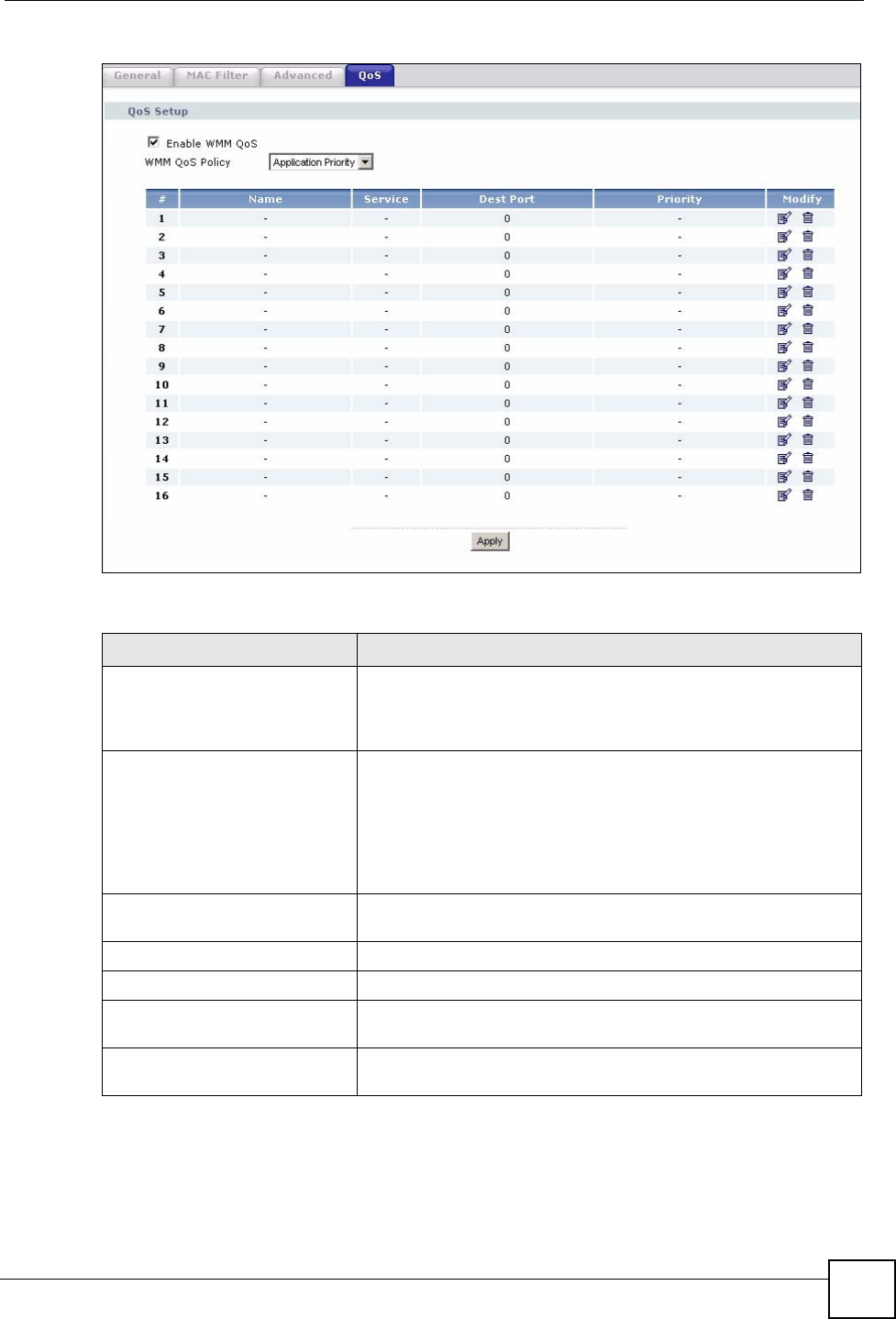
Click Network > Wireless LAN > QoS. The following screen appears.
Enable Intra-
BSS Traffic
A Basic Service Set (BSS) exists when all communications between wireless clients
or between a wireless client and a wired network client go through one access point
(AP).
Intra-BSS traffic is traffic between wireless clients in the BSS. When Intra-BSS is
enabled, wireless client A and B can access the wired network and communicate
with each other. When Intra-BSS is disabled, wireless client A and B can still access
the wired network but cannot communicate with each other.
Output Power Set the output power of the NBG318S in this field. If there is a high density of APs
within an area, decrease the output power of the NBG318S to reduce interference
with other APs.
802.11 Mode Select 802.11b to allow only IEEE 802.11b compliant WLAN devices to associate
with the NBG318S.
Select 802.11g to allow only IEEE 802.11g compliant WLAN devices to associate
with the NBG318S.
Select 802.11b/g to allow either IEEE802.11b or IEEE802.11g compliant WLAN
devices to associate with the NBG318S. The transmission rate of your NBG318S
might be reduced.
Super G Mode Use this field to enable or disable the Super G function. Super G mode is available
only if you select 802.11g or 802.11b/g in the 802.11 Mode field.
Super G provides higher data transmission rates than 802.11g.
Select Disabled if your wireless clients do not support Super G.
Select Super G with Dynamic Turbo if some or all of your wireless clients support
Super G with Dynamic Turbo. Dynamic Turbo uses two channels bonded together to
achieve higher transmission rates than 802.11g or Super G without Dynamic Turbo.
Dynamic turbo is on only when all wireless devices on the network support it. The
wireless channel is automatically fixed at 6 if you select this mode.
Select Super G without Turbo if the wireless clients on your network support Super
G but do not support dynamic turbo.
Apply Click Apply to save your changes back to the NBG318S.
Reset Click Reset to reload the previous configuration for this screen.
Table 30 Network > Wireless LAN > Advanced
LABEL DESCRIPTION
Chapter 5 Wireless LAN
NBG318S User’s Guide 89
Figure 52 Network > Wireless LAN > QoS
The following table describes the labels in this screen.
Table 31 Network > Wireless LAN > QoS
LABEL DESCRIPTION
Enable WMM QoS Select this to turn on WMM QoS (Wireless MultiMedia Quality of
Service). The NBG318S assigns priority to packets based on the
802.1q or DSCP information in their headers. If a packet has no
WMM information in its header, it is assigned the default priority.
WMM QoS Policy Select Default to have the NBG318S automatically give a service a
priority level according to the ToS value in the IP header of packets
it sends. WMM QoS (Wifi MultiMedia Quality of Service) gives high
priority to voice and video, which makes them run more smoothly.
Select Application Priority from the drop-down list box to display a
table of application names, services, ports and priorities to which
you want to apply WMM QoS.
The table appears only if you select Application Priority in WMM
QoS Policy.
# This is the number of an individual application entry.
Name This field displays a description given to an application entry.
Service This field displays either FTP, WWW, E-mail or a User Defined
service to which you want to apply WMM QoS.
Dest Port This field displays the destination port number to which the
application sends traffic.
Chapter 5 Wireless LAN
NBG318S User’s Guide
90
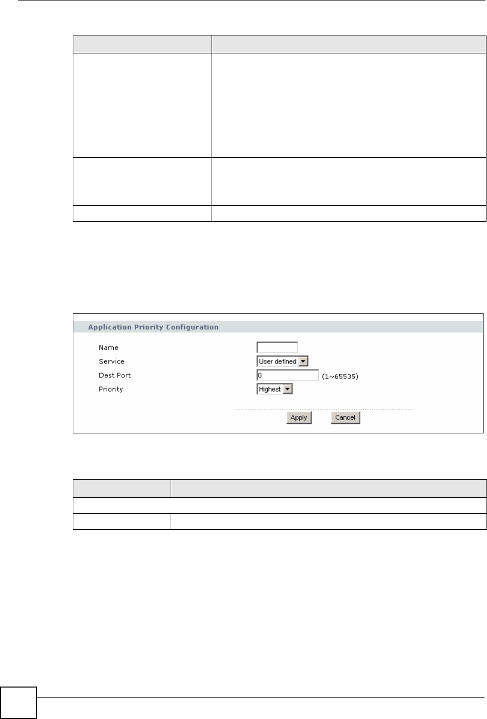
5.8.1 Application Priority Configuration
Use this screen to edit a WMM QoS application entry. Click the edit icon under Modify. The
following screen displays.
Figure 53 Network > Wireless LAN > QoS: Application Priority Configuration
See Appendix F on page 271 for a list of commonly-used services and destination ports. The
following table describes the fields in this screen.
Priority This field displays the priority of the application.
Highest - Typically used for voice or video that should be high-
quality.
High - Typically used for voice or video that can be medium-quality.
Mid - Typically used for applications that do not fit into another
priority. For example, Internet surfing.
Low - Typically used for non-critical “background” applications,
such as large file transfers and print jobs that should not affect
other applications.
Modify Click the Edit icon to open the Application Priority Configuration
screen. Modify an existing application entry or create a application
entry in the Application Priority Configuration screen.
Click the Remove icon to delete an application entry.
Apply Click Apply to save your changes to the NBG318S.
Table 31 Network > Wireless LAN > QoS (continued)
LABEL DESCRIPTION
Table 32 Network > Wireless LAN > QoS: Application Priority Configuration
LABEL DESCRIPTION
Application Priority Configuration
Name Type a description of the application priority.

Chapter 5 Wireless LAN
NBG318S User’s Guide 91
Service The following is a description of the applications you can prioritize with WMM
QoS. Select a service from the drop-down list box.
• E-Mail
Electronic mail consists of messages sent through a computer network to
specific groups or individuals. Here are some default ports for e-mail:
POP3 - port 110
IMAP - port 143
SMTP - port 25
HTTP - port 80
•FTP
File Transfer Protocol enables fast transfer of files, including large files that it
may not be possible to send via e-mail. FTP uses port number 21.
•WWW
The World Wide Web is an Internet system to distribute graphical, hyper-
linked information, based on Hyper Text Transfer Protocol (HTTP) - a client/
server protocol for the World Wide Web. The Web is not synonymous with the
Internet; rather, it is just one service on the Internet. Other services on the
Internet include Internet Relay Chat and Newsgroups. The Web is accessed
through use of a browser.
•User-Defined
User-defined services are user specific services configured using known ports
and applications.
Dest Port This displays the port the selected service uses. Type a port number in the
field provided if you want to use a different port to the default port.
Priority Select a priority from the drop-down list box.
Apply Click Apply to save your changes back to the NBG318S.
Cancel Click Cancel to return to the previous screen.
Table 32 Network > Wireless LAN > QoS: Application Priority Configuration (continued)
LABEL DESCRIPTION

Chapter 5 Wireless LAN
NBG318S User’s Guide
92

NBG318S User’s Guide 93
CHAPTER 6
WAN
This chapter describes how to configure WAN settings.
6.1 WAN Overview
See the chapter about the connection wizard for more information on the fields in the WAN
screens.
6.2 WAN MAC Address
The MAC address screen allows users to configure the WAN port's MAC address by either
using the factory default or cloning the MAC address from a computer on your LAN. Choose
Factory Default to select the factory assigned default MAC Address.
Otherwise, click Clone the computer's MAC address - IP Address and enter the IP address
of the computer on the LAN whose MAC you are cloning. Once it is successfully configured,
the address will be copied to the rom file (ZyNOS configuration file). It will not change unless
you change the setting or upload a different ROM file. It is recommended that you clone the
MAC address prior to hooking up the WAN Port.
6.3 Multicast
Traditionally, IP packets are transmitted in one of either two ways - Unicast (1 sender - 1
recipient) or Broadcast (1 sender - everybody on the network). Multicast delivers IP packets to
a group of hosts on the network - not everybody and not just 1.
IGMP (Internet Group Multicast Protocol) is a network-layer protocol used to establish
membership in a Multicast group - it is not used to carry user data. IGMP version 2 (RFC
2236) is an improvement over version 1 (RFC 1112) but IGMP version 1 is still in wide use. If
you would like to read more detailed information about interoperability between IGMP
version 2 and version 1, please see sections 4 and 5 of RFC 2236. The class D IP address is
used to identify host groups and can be in the range 224.0.0.0 to 239.255.255.255. The address
224.0.0.0 is not assigned to any group and is used by IP multicast computers. The address
224.0.0.1 is used for query messages and is assigned to the permanent group of all IP hosts
(including gateways). All hosts must join the 224.0.0.1 group in order to participate in IGMP.
The address 224.0.0.2 is assigned to the multicast routers group.
Chapter 6 WAN
NBG318S User’s Guide
94
The NBG318S supports both IGMP version 1 (IGMP-v1) and IGMP version 2 (IGMP-v2).
At start up, the NBG318S queries all directly connected networks to gather group
membership. After that, the NBG318S periodically updates this information. IP multicasting
can be enabled/disabled on the NBG318S LAN and/or WAN interfaces in the web
configurator (LAN; WAN). Select None to disable IP multicasting on these interfaces.
6.4 Internet Connection
Use this screen to change your NBG318S’s Internet access settings. Click Network > WAN.
The screen differs according to the encapsulation you choose.
6.4.1 Ethernet Encapsulation
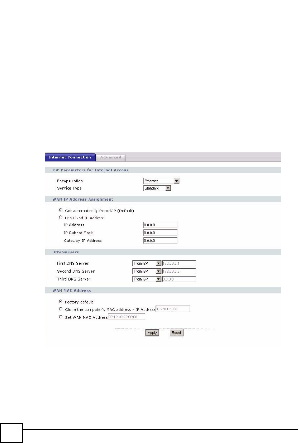
This screen displays when you select Ethernet encapsulation.
Figure 54 Network > WAN > Internet Connection: Ethernet Encapsulation

Chapter 6 WAN
NBG318S User’s Guide 95
The following table describes the labels in this screen.
Table 33 Network > WAN > Internet Connection: Ethernet Encapsulation
LABEL DESCRIPTION
Encapsulation You must choose the Ethernet option when the WAN port is used as a regular
Ethernet.
Service Type Choose from Standard, RR-Telstra (RoadRunner Telstra authentication
method), RR-Manager (Roadrunner Manager authentication method), RR-
Toshiba (Roadrunner Toshiba authentication method) or Telia Login.
The following fields do not appear with the Standard service type.
User Name Type the user name given to you by your ISP.
Password Type the password associated with the user name above.
Retype to Confirm Type your password again to make sure that you have entered is correctly.
Login Server IP
Address
Type the authentication server IP address here if your ISP gave you one.
This field is not available for Telia Login.
Login Server
(Telia Login only)
Type the domain name of the Telia login server, for example login1.telia.com.
Relogin
Every(min) (Telia
Login only)
The Telia server logs the NBG318S out if the NBG318S does not log in
periodically. Type the number of minutes from 1 to 59 (30 default) for the
NBG318S to wait between logins.
WAN IP Address Assignment
Get automatically
from ISP
Select this option If your ISP did not assign you a fixed IP address. This is the
default selection.
Use Fixed IP
Address
Select this option If the ISP assigned a fixed IP address.
IP Address Enter your WAN IP address in this field if you selected Use Fixed IP Address.
IP Subnet
Mask
Enter the IP Subnet Mask in this field.
Gateway IP
Address
Enter a Gateway IP Address (if your ISP gave you one) in this field.
DNS Servers
First DNS Server
Second DNS
Server
Third DNS Server
Select From ISP if your ISP dynamically assigns DNS server information (and the
NBG318S's WAN IP address). The field to the right displays the (read-only) DNS
server IP address that the ISP assigns.
Select User-Defined if you have the IP address of a DNS server. Enter the DNS
server's IP address in the field to the right. If you chose User-Defined, but leave
the IP address set to 0.0.0.0, User-Defined changes to None after you click
Apply. If you set a second choice to User-Defined, and enter the same IP
address, the second User-Defined changes to None after you click Apply.
Select None if you do not want to configure DNS servers. If you do not configure
a DNS server, you must know the IP address of a computer in order to access it.
WAN MAC
Address
The MAC address section allows users to configure the WAN port's MAC address
by either using the NBG318S’s MAC address, copying the MAC address from a
computer on your LAN or manually entering a MAC address.
Factory default Select Factory default to use the factory assigned default MAC Address.
Clone the
computer’s MAC
address
Select Clone the computer's MAC address - IP Address and enter the IP
address of the computer on the LAN whose MAC you are cloning. Once it is
successfully configured, the address will be copied to the rom file (ZyNOS
configuration file). It will not change unless you change the setting or upload a
different ROM file.

Chapter 6 WAN
NBG318S User’s Guide
96
6.4.2 PPPoE Encapsulation
The NBG318S supports PPPoE (Point-to-Point Protocol over Ethernet). PPPoE is an IETF
standard (RFC 2516) specifying how a personal computer (PC) interacts with a broadband
modem (DSL, cable, wireless, etc.) connection. The PPP over Ethernet option is for a dial-
up connection using PPPoE.
For the service provider, PPPoE offers an access and authentication method that works with
existing access control systems (for example Radius).
One of the benefits of PPPoE is the ability to let you access one of multiple network services,
a function known as dynamic service selection. This enables the service provider to easily
create and offer new IP services for individuals.
Operationally, PPPoE saves significant effort for both you and the ISP or carrier, as it requires
no specific configuration of the broadband modem at the customer site.
By implementing PPPoE directly on the NBG318S (rather than individual computers), the
computers on the LAN do not need PPPoE software installed, since the NBG318S does that
part of the task. Furthermore, with NAT, all of the LANs’ computers will have access.
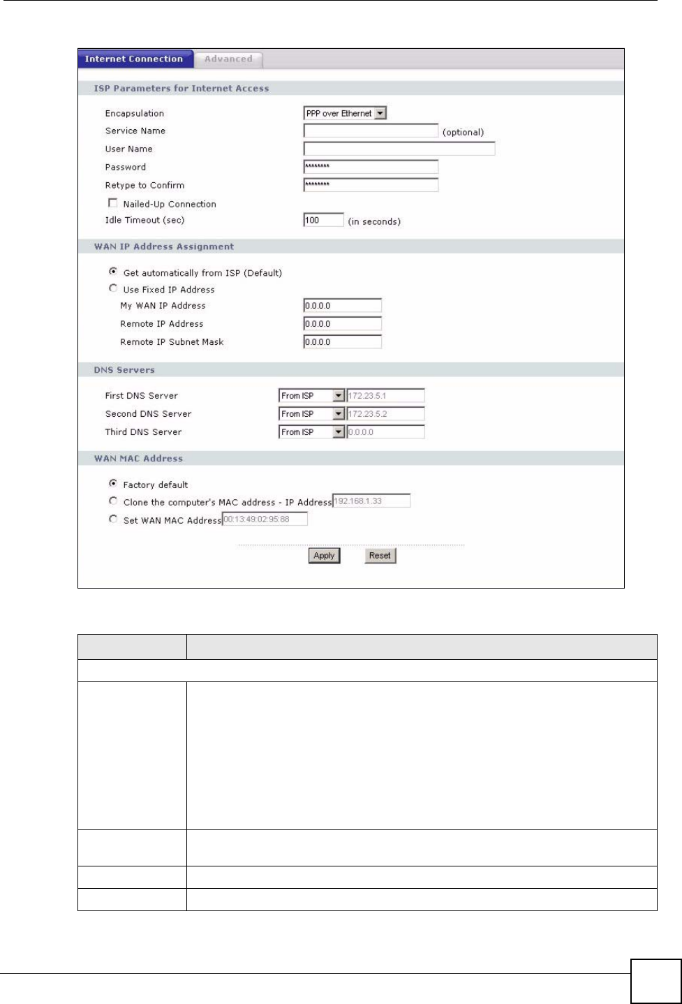
This screen displays when you select PPPoE encapsulation.
Set WAN MAC
Address
Select this option and enter the MAC address you want to use.
Apply Click Apply to save your changes back to the NBG318S.
Reset Click Reset to begin configuring this screen afresh.
Table 33 Network > WAN > Internet Connection: Ethernet Encapsulation
LABEL DESCRIPTION
Chapter 6 WAN
NBG318S User’s Guide 97
Figure 55 Network > WAN > Internet Connection: PPPoE Encapsulation
The following table describes the labels in this screen.
Table 34 Network > WAN > Internet Connection: PPPoE Encapsulation
LABEL DESCRIPTION
ISP Parameters for Internet Access
Encapsulation The PPP over Ethernet choice is for a dial-up connection using PPPoE. The
NBG318S supports PPPoE (Point-to-Point Protocol over Ethernet). PPPoE is an
IETF Draft standard (RFC 2516) specifying how a personal computer (PC)
interacts with a broadband modem (i.e. xDSL, cable, wireless, etc.) connection.
Operationally, PPPoE saves significant effort for both the end user and ISP/carrier,
as it requires no specific configuration of the broadband modem at the customer
site. By implementing PPPoE directly on the router rather than individual
computers, the computers on the LAN do not need PPPoE software installed, since
the router does that part of the task. Further, with NAT, all of the LAN's computers
will have access.
Service Name Type the PPPoE service name provided to you. PPPoE uses a service name to
identify and reach the PPPoE server.
User Name Type the user name given to you by your ISP.
Password Type the password associated with the user name above.

Chapter 6 WAN
NBG318S User’s Guide
98
6.4.3 PPTP Encapsulation
Point-to-Point Tunneling Protocol (PPTP) is a network protocol that enables secure transfer of
data from a remote client to a private server, creating a Virtual Private Network (VPN) using
TCP/IP-based networks.
Retype to
Confirm
Type your password again to make sure that you have entered is correctly.
Nailed-Up
Connection
Select Nailed-Up Connection if you do not want the connection to time out.
Idle Timeout This value specifies the time in seconds that elapses before the router
automatically disconnects from the PPPoE server.
WAN IP Address Assignment
Get automatically
from ISP
Select this option If your ISP did not assign you a fixed IP address. This is the
default selection.
Use Fixed IP
Address
Select this option If the ISP assigned a fixed IP address.
My WAN IP
Address
Enter your WAN IP address in this field if you selected Use Fixed IP Address.
Remote IP
Address
Enter the remote IP address (if your ISP gave you one) in this field.
Remote IP
Subnet Mask
Enter the remote IP subnet mask in this field.
DNS Servers
First DNS Server
Second DNS
Server
Third DNS Server
Select From ISP if your ISP dynamically assigns DNS server information (and the
NBG318S's WAN IP address). The field to the right displays the (read-only) DNS
server IP address that the ISP assigns.
Select User-Defined if you have the IP address of a DNS server. Enter the DNS
server's IP address in the field to the right. If you chose User-Defined, but leave
the IP address set to 0.0.0.0, User-Defined changes to None after you click
Apply. If you set a second choice to User-Defined, and enter the same IP
address, the second User-Defined changes to None after you click Apply.
Select None if you do not want to configure DNS servers. If you do not configure a
DNS server, you must know the IP address of a computer in order to access it.
WAN MAC
Address
The MAC address section allows users to configure the WAN port's MAC address
by using the NBG318S’s MAC address, copying the MAC address from a computer
on your LAN or manually entering a MAC address.
Factory default Select Factory default to use the factory assigned default MAC Address.
Clone the
computer’s MAC
address
Select Clone the computer's MAC address - IP Address and enter the IP
address of the computer on the LAN whose MAC you are cloning. Once it is
successfully configured, the address will be copied to the rom file (ZyNOS
configuration file). It will not change unless you change the setting or upload a
different ROM file.
Set WAN MAC
Address
Select this option and enter the MAC address you want to use.
Apply Click Apply to save your changes back to the NBG318S.
Reset Click Reset to begin configuring this screen afresh.
Table 34 Network > WAN > Internet Connection: PPPoE Encapsulation
LABEL DESCRIPTION
Chapter 6 WAN
NBG318S User’s Guide 99
PPTP supports on-demand, multi-protocol and virtual private networking over public
networks, such as the Internet.
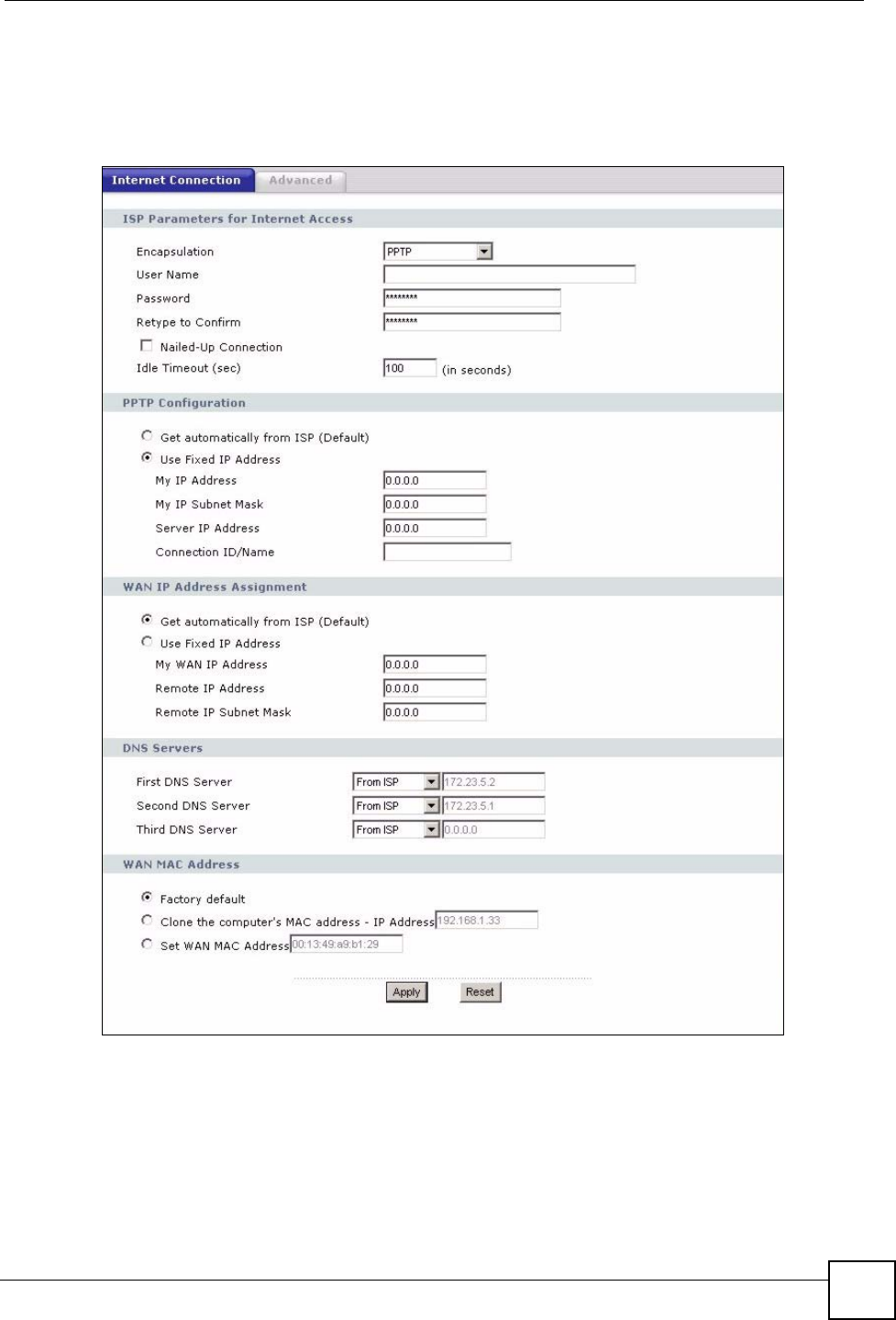
This screen displays when you select PPTP encapsulation.
Figure 56 Network > WAN > Internet Connection: PPTP Encapsulation

Chapter 6 WAN
NBG318S User’s Guide
100
The following table describes the labels in this screen.
Table 35 Network > WAN > Internet Connection: PPTP Encapsulation
LABEL DESCRIPTION
ISP Parameters for Internet Access
Encapsulation Point-to-Point Tunneling Protocol (PPTP) is a network protocol that enables
secure transfer of data from a remote client to a private server, creating a
Virtual Private Network (VPN) using TCP/IP-based networks. PPTP supports
on-demand, multi-protocol, and virtual private networking over public
networks, such as the Internet. The NBG318S supports only one PPTP server
connection at any given time.
To configure a PPTP client, you must configure the User Name and
Password fields for a PPP connection and the PPTP parameters for a PPTP
connection.
User Name Type the user name given to you by your ISP.
Password Type the password associated with the User Name above.
Retype to Confirm Type your password again to make sure that you have entered is correctly.
Nailed-up Connection Select Nailed-Up Connection if you do not want the connection to time out.
Idle Timeout This value specifies the time in seconds that elapses before the NBG318S
automatically disconnects from the PPTP server.
PPTP Configuration
Get automatically from
ISP
Select this option If your ISP did not assign you a fixed IP address. This is the
default selection.
Use Fixed IP Address Select this option If the ISP assigned a fixed IP address.
My IP Address Type the (static) IP address assigned to you by your ISP.
My IP Subnet
Mask
Your NBG318S will automatically calculate the subnet mask based on the IP
address that you assign. Unless you are implementing subnetting, use the
subnet mask computed by the NBG318S.
Server IP Address Type the IP address of the PPTP server.
Connection ID/
Name
Type your identification name for the PPTP server.
WAN IP Address Assignment
Get automatically from
ISP
Select this option If your ISP did not assign you a fixed IP address. This is the
default selection.
Use Fixed IP Address Select this option If the ISP assigned a fixed IP address.
My WAN IP
Address
Enter your WAN IP address in this field if you selected Use Fixed IP
Address.
Remote IP
Address
Enter the remote IP address (if your ISP gave you one) in this field.
Remote IP Subnet
Mask
Enter the remote IP subnet mask in this field.
DNS Servers
Chapter 6 WAN
NBG318S User’s Guide 101
6.5 Advanced WAN Screen
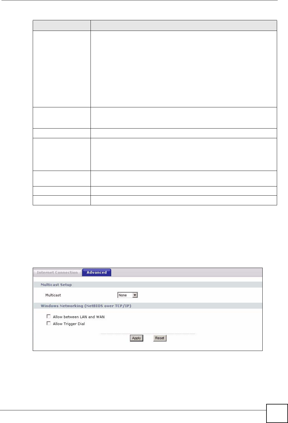
To change your NBG318S’s advanced WAN settings, click Network > WAN > Advanced.
The screen appears as shown.
Figure 57 Network > WAN > Advanced
First DNS Server
Second DNS Server
Third DNS Server
Select From ISP if your ISP dynamically assigns DNS server information (and
the NBG318S's WAN IP address). The field to the right displays the (read-
only) DNS server IP address that the ISP assigns.
Select User-Defined if you have the IP address of a DNS server. Enter the
DNS server's IP address in the field to the right. If you chose User-Defined,
but leave the IP address set to 0.0.0.0, User-Defined changes to None after
you click Apply. If you set a second choice to User-Defined, and enter the
same IP address, the second User-Defined changes to None after you click
Apply.
Select None if you do not want to configure DNS servers. If you do not
configure a DNS server, you must know the IP address of a computer in order
to access it.
WAN MAC Address The MAC address section allows users to configure the WAN port's MAC
address by either using the NBG318S’s MAC address, copying the MAC
address from a computer on your LAN or manually entering a MAC address.
Factory default Select Factory default to use the factory assigned default MAC Address.
Clone the computer’s
MAC address
Select Clone the computer's MAC address - IP Address and enter the IP
address of the computer on the LAN whose MAC you are cloning. Once it is
successfully configured, the address will be copied to the rom file (ZyNOS
configuration file). It will not change unless you change the setting or upload a
different ROM file.
Set WAN MAC
Address
Select this option and enter the MAC address you want to use.
Apply Click Apply to save your changes back to the NBG318S.
Reset Click Reset to begin configuring this screen afresh.
Table 35 Network > WAN > Internet Connection: PPTP Encapsulation
LABEL DESCRIPTION

Chapter 6 WAN
NBG318S User’s Guide
102
The following table describes the labels in this screen.
Table 36 WAN > Advanced
LABEL DESCRIPTION
Multicast Setup
Multicast Select IGMP V-1, IGMP V-2 or None. IGMP (Internet Group Multicast
Protocol) is a network-layer protocol used to establish membership in a
Multicast group - it is not used to carry user data. IGMP version 2 (RFC 2236)
is an improvement over version 1 (RFC 1112) but IGMP version 1 is still in
wide use. If you would like to read more detailed information about
interoperability between IGMP version 2 and version 1, please see sections 4
and 5 of RFC 2236.
Windows Networking (NetBIOS over TCP/IP): NetBIOS (Network Basic Input/Output System) are TCP
or UDP broadcast packets that enable a computer to connect to and communicate with a LAN. For
some dial-up services such as PPPoE or PPTP, NetBIOS packets cause unwanted calls. However it
may sometimes be necessary to allow NetBIOS packets to pass through to the WAN in order to find a
computer on the WAN.
Allow between LAN
and WAN
Select this check box to forward NetBIOS packets from the LAN to the WAN
and from the WAN to the LAN. If your firewall is enabled with the default
policy set to block WAN to LAN traffic, you also need to enable the default
WAN to LAN firewall rule that forwards NetBIOS traffic.
Clear this check box to block all NetBIOS packets going from the LAN to the
WAN and from the WAN to the LAN.
Allow Trigger Dial Select this option to allow NetBIOS packets to initiate calls.
Apply Click Apply to save your changes back to the NBG318S.
Reset Click Reset to begin configuring this screen afresh.

NBG318S User’s Guide 103
CHAPTER 7
LAN
This chapter describes how to configure LAN settings.
7.1 LAN Overview
A Local Area Network (LAN) is a shared communication system to which many computers
are attached. A LAN is a computer network limited to the immediate area, usually the same
building or floor of a building. The LAN screens can help you configure a LAN DHCP server,
manage IP addresses, and partition your physical network into logical networks.
7.1.1 IP Pool Setup
The NBG318S is pre-configured with a pool of 32 IP addresses starting from 192.168.1.33 to
192.168.1.64. This configuration leaves 31 IP addresses (excluding the NBG318S itself) in the
lower range (192.168.1.2 to 192.168.1.32) for other server computers, for instance, servers for
mail, FTP, TFTP, web, etc., that you may have.
7.1.2 System DNS Servers
Refer to the IP address and subnet mask section in the Connection Wizard chapter.
7.2 LAN TCP/IP
The NBG318S has built-in DHCP server capability that assigns IP addresses and DNS servers
to systems that support DHCP client capability.
7.2.1 Factory LAN Defaults
The LAN parameters of the NBG318S are preset in the factory with the following values:
• IP address of 192.168.1.1 with subnet mask of 255.255.255.0 (24 bits)
• DHCP server enabled with 32 client IP addresses starting from 192.168.1.33.
These parameters should work for the majority of installations. If your ISP gives you explicit
DNS server address(es), read the embedded web configurator help regarding what fields need
to be configured.

Chapter 7 LAN
NBG318S User’s Guide
104
7.2.2 IP Address and Subnet Mask
Refer to the IP address and subnet mask section in the Connection Wizard chapter for this
information.
7.2.3 Multicast
Traditionally, IP packets are transmitted in one of either two ways - Unicast (1 sender - 1
recipient) or Broadcast (1 sender - everybody on the network). Multicast delivers IP packets to
a group of hosts on the network - not everybody and not just 1.
IGMP (Internet Group Multicast Protocol) is a network-layer protocol used to establish
membership in a Multicast group - it is not used to carry user data. IGMP version 2 (RFC
2236) is an improvement over version 1 (RFC 1112) but IGMP version 1 is still in wide use. If
you would like to read more detailed information about interoperability between IGMP
version 2 and version 1, please see sections 4 and 5 of RFC 2236. The class D IP address is
used to identify host groups and can be in the range 224.0.0.0 to 239.255.255.255. The address
224.0.0.0 is not assigned to any group and is used by IP multicast computers. The address
224.0.0.1 is used for query messages and is assigned to the permanent group of all IP hosts
(including gateways). All hosts must join the 224.0.0.1 group in order to participate in IGMP.
The address 224.0.0.2 is assigned to the multicast routers group.
The NBG318S supports both IGMP version 1 (IGMP-v1) and IGMP version 2 (IGMP-v2).
At start up, the NBG318S queries all directly connected networks to gather group
membership. After that, the NBG318S periodically updates this information. IP multicasting
can be enabled/disabled on the NBG318S LAN and/or WAN interfaces in the web
configurator (LAN; WAN). Select None to disable IP multicasting on these interfaces.
7.2.4 Any IP
Traditionally, you must set the IP addresses and the subnet masks of a computer and the
NBG318S to be in the same subnet to allow the computer to access the Internet (through the
NBG318S). In cases where your computer is required to use a static IP address in another
network, you may need to manually configure the network settings of the computer every time
you want to access the Internet via the NBG318S.
With the Any IP feature and NAT enabled, the NBG318S allows a computer to access the
Internet without changing the network settings (such as IP address and subnet mask) of the
computer, when the IP addresses of the computer and the NBG318S are not in the same
subnet. Whether a computer is set to use a dynamic or static (fixed) IP address, you can simply
connect the computer to the NBG318S and access the Internet.
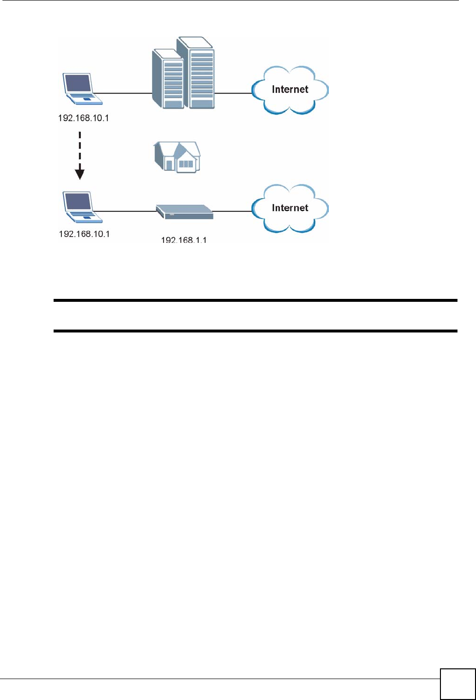
The following figure depicts a scenario where a computer is set to use a static private IP
address in the corporate environment. In a residential house where a NBG318S is installed,
you can still use the computer to access the Internet without changing the network settings,
even when the IP addresses of the computer and the NBG318S are not in the same subnet.
Chapter 7 LAN
NBG318S User’s Guide 105
Figure 58 Any IP Example
The Any IP feature does not apply to a computer using either a dynamic IP address or a static
IP address that is in the same subnet as the NBG318S’s IP address.
"You must enable NAT to use the Any IP feature on the NBG318S.
Address Resolution Protocol (ARP) is a protocol for mapping an Internet Protocol address (IP
address) to a physical machine address, also known as a Media Access Control or MAC
address, on the local area network. IP routing table is defined on IP Ethernet devices (the
NBG318S) to decide which hop to use, to help forward data along to its specified destination.
The following lists out the steps taken, when a computer tries to access the Internet for the first
time through the NBG318S.
1When a computer (which is in a different subnet) first attempts to access the Internet, it
sends packets to its default gateway (which is not the NBG318S) by looking at the MAC
address in its ARP table.
2When the computer cannot locate the default gateway, an ARP request is broadcast on
the LAN.
3The NBG318S receives the ARP request and replies to the computer with its own MAC
address.
4The computer updates the MAC address for the default gateway to the ARP table. Once
the ARP table is updated, the computer is able to access the Internet through the
NBG318S.
5When the NBG318S receives packets from the computer, it creates an entry in the IP
routing table so it can properly forward packets intended for the computer.
After all the routing information is updated, the computer can access the NBG318S and the
Internet as if it is in the same subnet as the NBG318S.
Chapter 7 LAN
NBG318S User’s Guide
106
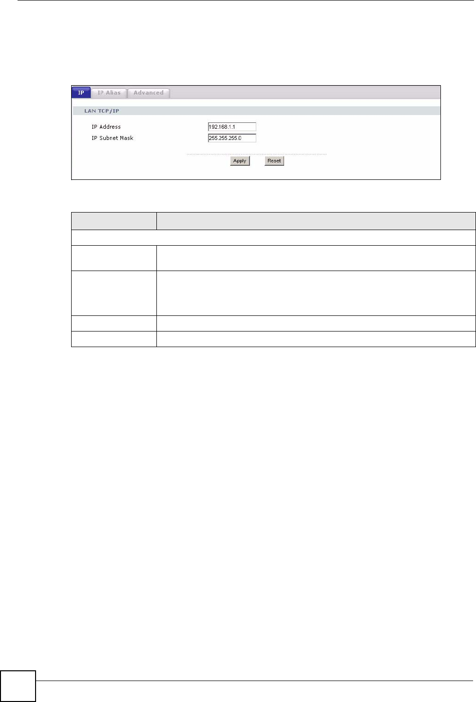
7.3 LAN IP Screen
Use this screen to change your basic LAN settings. Click Network > LAN.
Figure 59 Network > LAN > IP
The following table describes the labels in this screen.
7.4 LAN IP Alias
IP alias allows you to partition a physical network into different logical networks over the
same Ethernet interface. The NBG318S supports three logical LAN interfaces via its single
physical Ethernet interface with the NBG318S itself as the gateway for each LAN network.
To change your NBG318S’s IP alias settings, click Network > LAN > IP Alias. The screen
appears as shown.
Table 37 Network > LAN > IP
LABEL DESCRIPTION
LAN TCP/IP
IP Address Type the IP address of your NBG318S in dotted decimal notation 192.168.1.1
(factory default).
IP Subnet Mask The subnet mask specifies the network number portion of an IP address. Your
NBG318S will automatically calculate the subnet mask based on the IP address
that you assign. Unless you are implementing subnetting, use the subnet mask
computed by the NBG318S.
Apply Click Apply to save your changes back to the NBG318S.
Reset Click Reset to begin configuring this screen afresh.
Chapter 7 LAN
NBG318S User’s Guide 107
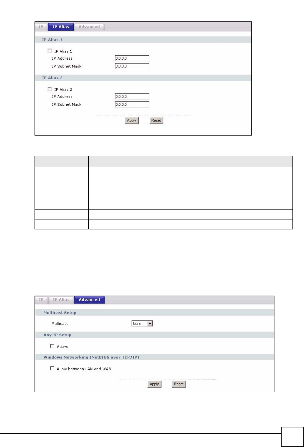
Figure 60 Network > LAN > IP Alias
The following table describes the labels in this screen.
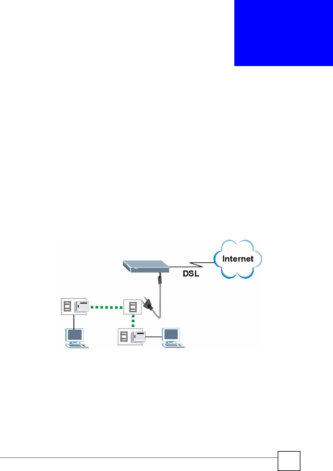
7.5 Advanced LAN Screen
To change your NBG318S’s advanced IP settings, click Network > LAN > Advanced. The
screen appears as shown.
Figure 61 Network > LAN > Advanced
Table 38 Network > LAN > IP Alias
LABEL DESCRIPTION
IP Alias 1,2 Select the check box to configure another LAN network for the NBG318S.
IP Address Enter the IP address of your NBG318S in dotted decimal notation.
IP Subnet Mask Your NBG318S will automatically calculate the subnet mask based on the IP
address that you assign. Unless you are implementing subnetting, use the
subnet mask computed by the NBG318S.
Apply Click Apply to save your changes back to the NBG318S.
Reset Click Reset to begin configuring this screen afresh.

Chapter 7 LAN
NBG318S User’s Guide
108
The following table describes the labels in this screen.
Table 39 Network > LAN > Advanced
LABEL DESCRIPTION
Multicast Select IGMP V-1 or IGMP V-2 or None. IGMP (Internet Group Multicast
Protocol) is a network-layer protocol used to establish membership in a
Multicast group - it is not used to carry user data. IGMP version 2 (RFC 2236)
is an improvement over version 1 (RFC 1112) but IGMP version 1 is still in
wide use. If you would like to read more detailed information about
interoperability between IGMP version 2 and version 1, please see sections 4
and 5 of RFC 2236.
Any IP Setup
Active Select this if you want to let computers on different subnets use the
NBG318S.
Windows Networking (NetBIOS over TCP/IP): NetBIOS (Network Basic Input/Output System) are TCP
or UDP broadcast packets that enable a computer to connect to and communicate with a LAN. For
some dial-up services such as PPPoE or PPTP, NetBIOS packets cause unwanted calls. However it
may sometimes be necessary to allow NetBIOS packets to pass through to the WAN in order to find a
computer on the WAN.
Allow between LAN
and WAN
Select this check box to forward NetBIOS packets from the LAN to the WAN
and from the WAN to the LAN. If your firewall is enabled with the default policy
set to block WAN to LAN traffic, you also need to enable the default WAN to
LAN firewall rule that forwards NetBIOS traffic.
Clear this check box to block all NetBIOS packets going from the LAN to the
WAN and from the WAN to the LAN.
Apply Click Apply to save your changes back to the NBG318S.
Reset Click Reset to begin configuring this screen afresh.
NBG318S User’s Guide 109
CHAPTER 8
HomePlug AV
This chapter introduces the main applications and management of the powerline feature.
8.1 Overview
The NBG318S is a HomePlug AV compliant powerline Ethernet adapter. The NBG318S and
other HomePlug AV powerline adapters in your network communicate with each other by
sending and receiving information over your home’s electrical wiring.
The NBG318S plugs into an ordinary outlet to create a new network which can extend to any
other electrical outlet in any room of a house.
The following section shows you a typical application.
Figure 62 Expand Your Network
To set up your powerline network do the following.
1Connect your NBG318S to the Internet.
2Then plug your NBG318S into a power outlet.
The NBG318S is ready for connection on a powerline network.
3Connect another HomePlug AV compatible adapter to a computer and then plug it in on
the same home or office wiring.

Chapter 8 HomePlug AV
NBG318S User’s Guide
110
After configuring the settings on all adapters (see Section 8.3 on page 112) your computer can
now connect to the powerline network and to the Internet. Your powerline network can be
further expanded by plugging additional powerline adapters into other outlets in your home
and connecting other computers or network devices (for example, a printer) to them.
In this User’s Guide the electrical wiring network may be referred to as the “powerline
network”.
8.2 Privacy and Powerline Adapters
When the NBG318S communicates with each other HomePlug AV compliant powerline
adapters, they use encryption to scramble the information that is sent in the powerline
network. Encryption is like a secret code. If you do not know the secret code, you cannot
understand the message. The HomePlug AV standard uses 128-bit AES (Advanced
Encryption Standard) to safely transmit data between powerline adapters.
For the NBG318S and powerline adapters to communicate with each other they all need to use
the same Network Membership Key (NMK). Otherwise, they cannot unscramble the
encrypted data sent in the powerline network.
The NMK is derived from the network password you assign to the NBG318S and powerline
adapters. By default all HomePlug powerline adapters are configured with the network
password HomePlugAV. This allows all HomePlug powerline adapters and the NBG318S to
communicate with each other without any software configuration. This also means that if you
don’t change the network password, any HomePlug AV powerline adapter connected to your
powerline circuit can see your network data.
"Change the network password on your powerline adapters to ensure secure
data transmission on your powerline network.
8.2.1 Setting Up a Private Powerline Network
To prevent others compromising your network security, you can create a private network.
Create a private network by changing the network password only on the powerline adapters
you want to communicate in your network. The NBG318S and powerline adapters convert the
network password to a Network Membership Key (NMK). Only the powerline adapters with
the same NMK can communicate in your network.
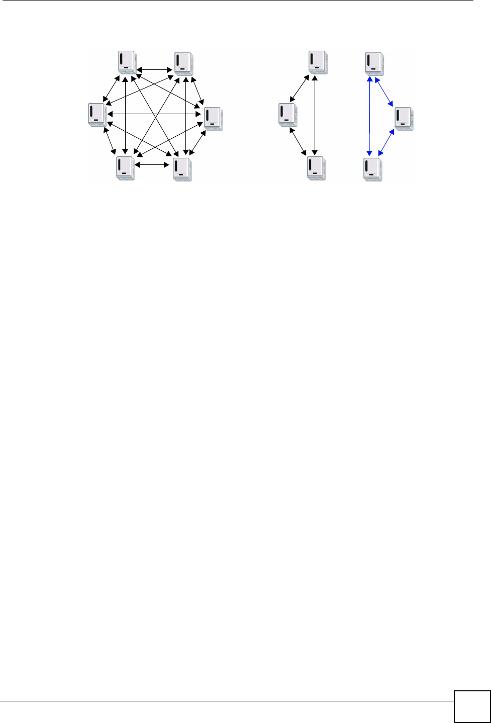
The following figure shows a scenario A - where all the powerline adapters have the same
NMK (NMK1) and scenario B - where some adapters use NMK1 and some use NMK2.
Chapter 8 HomePlug AV
NBG318S User’s Guide 111
Figure 63 Powerline Network Scenario
In both cases the powerline adapters reside on the same electrical circuit. In scenario A all the
powerline adapters can communicate with each other. In scenario B only the adapters with the
same NMK can receive and unscramble communication between each other.
8.2.2 Setting Up Multiple Powerline Networks.
Multiple powerline networks can coexist on a single powerline circuit. You might want to
implement multiple powerline networks in a small office environment where you have two
separate Ethernet networks.
Connect one powerline adapter to a router or switch on the first Ethernet network and assign a
network password (for example, “Password1”) to this powerline adapter. Add additional
powerline adapters to your network by plugging them into your powerline outlets and
assigning them the same network password, “Password1”. This completes the configuration of
your first powerline network.
Connect another powerline adapter to a router or switch on the second Ethernet network and
assign a different network password (for example “Password2”) to this powerline adapter.
Again, add additional powerline adapters and assign them the same second network password,
“Password2”.
You now have two private networks on your powerline circuit. Information is not shared
between the two networks as only powerline adapters with the same password can
communicate with each other. The following figure shows two private powerline networks on
the same electrical circuit.
AB
NMK1
NMK1
NMK1
NMK1
NMK1
NMK1
NMK1
NMK1
NMK1
NMK2
NMK2
NMK2
Chapter 8 HomePlug AV
NBG318S User’s Guide
112
Figure 64 Two Private Powerline Networks on One Circuit
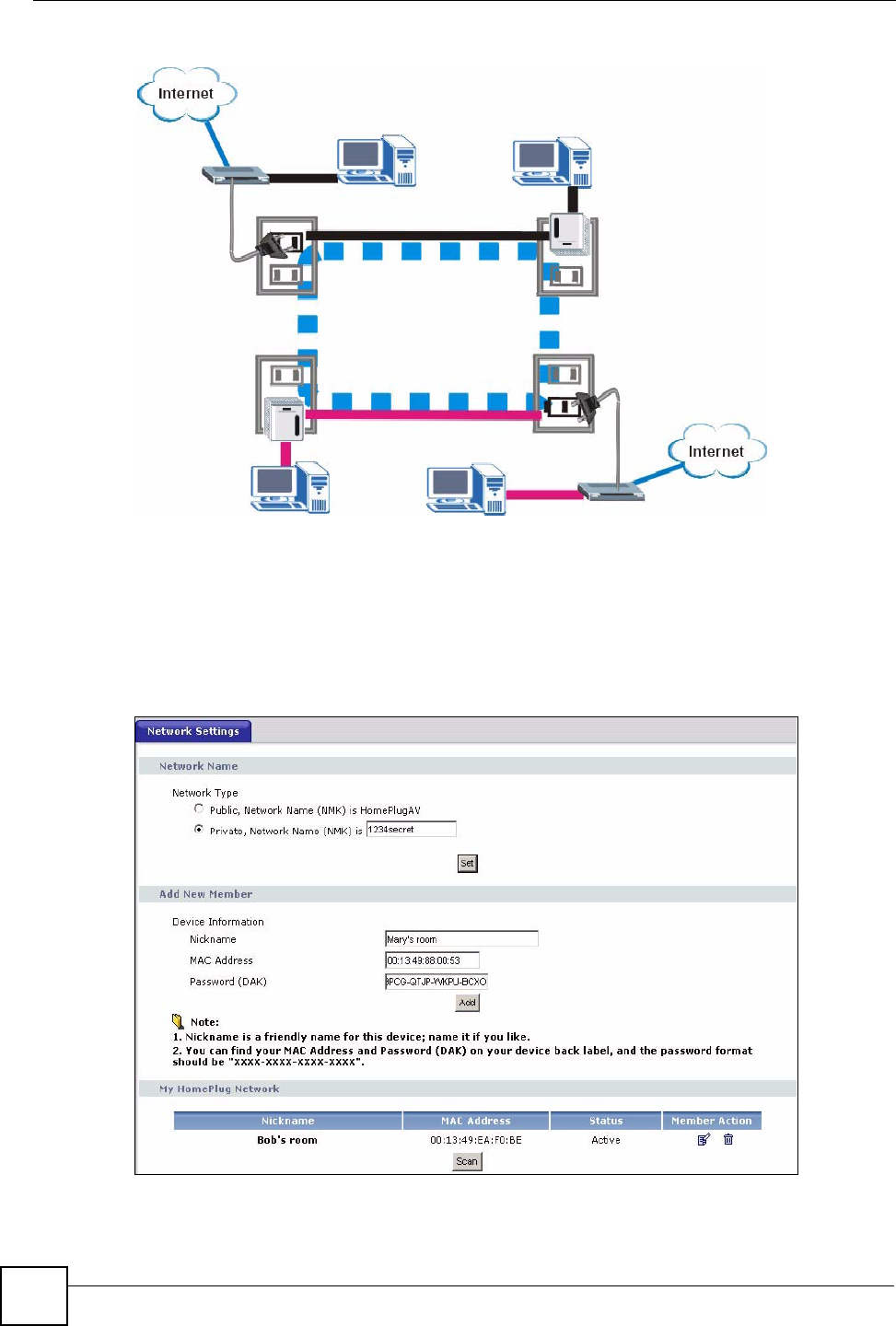
8.3 Configuring Your HomePlug AV Devices
Click on Network > HomePlug to see the screen below. Use this screen to set up a HomePlug
AV network and to check the status of HomePlug AV devices on your electrical circuit.
Figure 65 Network > HomePlug > Network Settings
The following table describes the labels in the screen.
Password 1
Password 2
Password 2
Password 1

Chapter 8 HomePlug AV
NBG318S User’s Guide 113
Table 40 Network > HomePlug > Network Settings
LABEL DESCRIPTION
Network Name This section lets you set the name of your network and to make it
either public or private.
The Network Name performs the same function as a network
password. All devices on your HomePlug network have the same
Network Name. A device with a different Network Name cannot be
on your network.
You can add other HomePlugAV devices to your network by giving
them the same Network Name.
Network Type The network may be either public or private.
Public, Network
Name (NMK) is
HomePlug AV
Select this option if you want to make your powerline network public
with the default Network Name of “HomePlug AV”. Since this is a
well known NMK it is less secure than a private NMK.
Private, Network
Name (NMK) is
Select this option if you wish to make your powerline network more
secure with a private Network Name. Type the name of your private
powerline network in the field. You may enter up to 64 alphanumeric
characters for the Network Name.
Set Click Set to change the Network Name of all the devices currently in
your network.
Add New Member This section lets you add new Home Plug AV enabled devices to
your powerline network. When you add the device it is given the
current Network Name.
Device Information In this section type information to identify the new powerline device
you are adding on your network.
Nickname Type a name you wish to use to identify a specific powerline
adapter, for example, “Mary’s room”.
MAC Address Type the MAC address of the adapter you wish to add. The MAC
address of your powerline adapter can be found by looking at the
label on your device. It consists of six pairs of hexadecimal
characters (hexadecimal characters are “0-9” and “a-f”). In the case
of the NBG318S, this label is on the bottom of the device.
Password (DAK) The Password (DAK) (DAK stands for Device Access Key), is used
to verify that you are authorized to perform changes on a device.
You can find the DAK printed on a sticker on the bottom of a
HomePlug enabled device.
My Homeplug
Network
This section provides information on the HomePlug AV devices in
your network (or that were previously connected on it but are
currently disconnected).
Nickname This is the nickname you gave to the HomePlug AV device.
MAC Address This is the MAC address of the HomePlug AV device.
Status This field shows the status of the device. If the field shows Active,
then the device is connected to your network. If the field shows Out
of Network, the device has been added to the network but it is not
ready. Check whether it is turned on and connected. If the field
shows Not Member, it is not on the network. The NBG318S is
aware of it, but cannot manage the device. If you click Set, the
device’s Network Name will not change. You can add it to the
network by clicking on Edit or entering its details in the Add New
member section.
Chapter 8 HomePlug AV
NBG318S User’s Guide
114
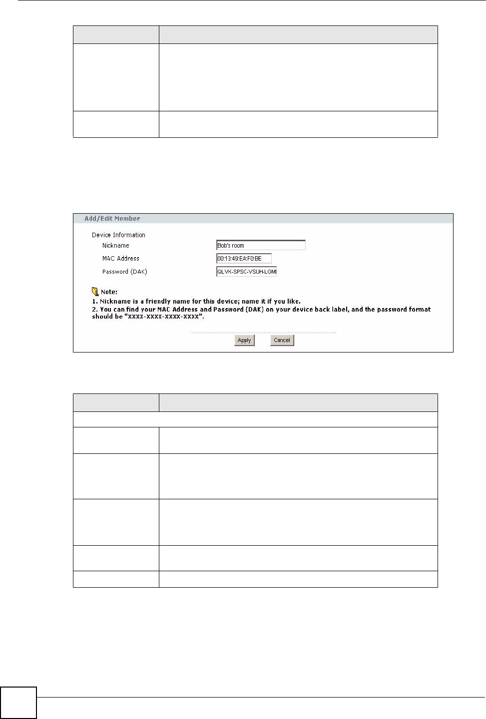
Click on Network > HomePlug > Edit to see the screen below. Use this screen to add a new
HomePlug AV device to the network. You can also edit a device’s details.
Figure 66 Network > HomePlug > Edit
The following table describes the labels in the screen.
Table 41 Network > HomePlug > Edit
Member Action This field shows the Edit icon and the Delete icon. Click on Edit to
add a device to the network or to edit details such as the device’s
Nickname. Click on Delete to remove the device from the network.
If you want to set up a second network, remove the devices from My
HomePlug Network that you want to keep in your first network
before you set the new Network Name for the second network.
Scan Click Scan to detect devices on the same electrical circuit as the
NBG318S.
LABEL DESCRIPTION
Device Information
Nickname Type a name you wish to use to identify a specific powerline
adapter, for example, “Bob’s room”.
MAC Address This is the MAC address of the HomePlug AV device. The MAC
Address will appear in this field if the device’s status is either Active
or Not Member. If the device’s status is Out of Network or your
NBG318S can not detect it, type the MAC Address here.
Password (DAK) The Password (DAK) (DAK stands for Device Access Key), is used
to verify that you are authorized to perform changes on a device.
You can find the DAK printed on a sticker on the bottom of a
HomePlug enabled device.
Apply Click this button to apply add the device to the network or to apply
your changes.
Cancel Click this button to return to the previous screen.
LABEL DESCRIPTION
NBG318S User’s Guide 115
CHAPTER 9
DHCP
9.1 DHCP
DHCP (Dynamic Host Configuration Protocol, RFC 2131 and RFC 2132) allows individual
clients to obtain TCP/IP configuration at start-up from a server. You can configure the
NBG318S as a DHCP server or disable it. When configured as a server, the NBG318S
provides the TCP/IP configuration for the clients. If DHCP service is disabled, you must have
another DHCP server on your LAN, or else the computer must be manually configured.
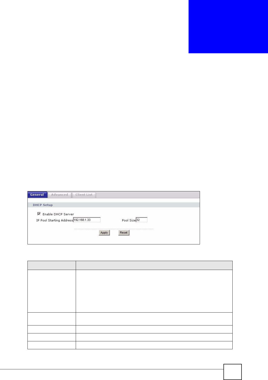
9.2 DHCP Server General Screen
Click Network > DHCP Server. The following screen displays.
Figure 67 Network > DHCP Server > General
The following table describes the labels in this screen.
Table 42 Network > DHCP Server > General
LABEL DESCRIPTION
Enable DHCP Server DHCP (Dynamic Host Configuration Protocol, RFC 2131 and RFC 2132)
allows individual clients (computers) to obtain TCP/IP configuration at startup
from a server. Leave the Enable DHCP Server check box selected unless
your ISP instructs you to do otherwise. Clear it to disable the NBG318S acting
as a DHCP server. When configured as a server, the NBG318S provides
TCP/IP configuration for the clients. If not, DHCP service is disabled and you
must have another DHCP server on your LAN, or else the computers must be
manually configured. When set as a server, fill in the following four fields.
IP Pool Starting
Address
This field specifies the first of the contiguous addresses in the IP address
pool.
Pool Size This field specifies the size, or count of the IP address pool.
Apply Click Apply to save your changes back to the NBG318S.
Reset Click Reset to begin configuring this screen afresh.
Chapter 9 DHCP
NBG318S User’s Guide
116
9.3 DHCP Server Advanced Screen
This screen allows you to assign IP addresses on the LAN to specific individual computers
based on their MAC addresses. You can also use this screen to configure the DNS server
information that the NBG318S sends to the DHCP clients.
Every Ethernet device has a unique MAC (Media Access Control) address. The MAC address
is assigned at the factory and consists of six pairs of hexadecimal characters, for example,
00:A0:C5:00:00:02.
To change your NBG318S’s static DHCP settings, click Network > DHCP Server >
Advanced. The following screen displays.
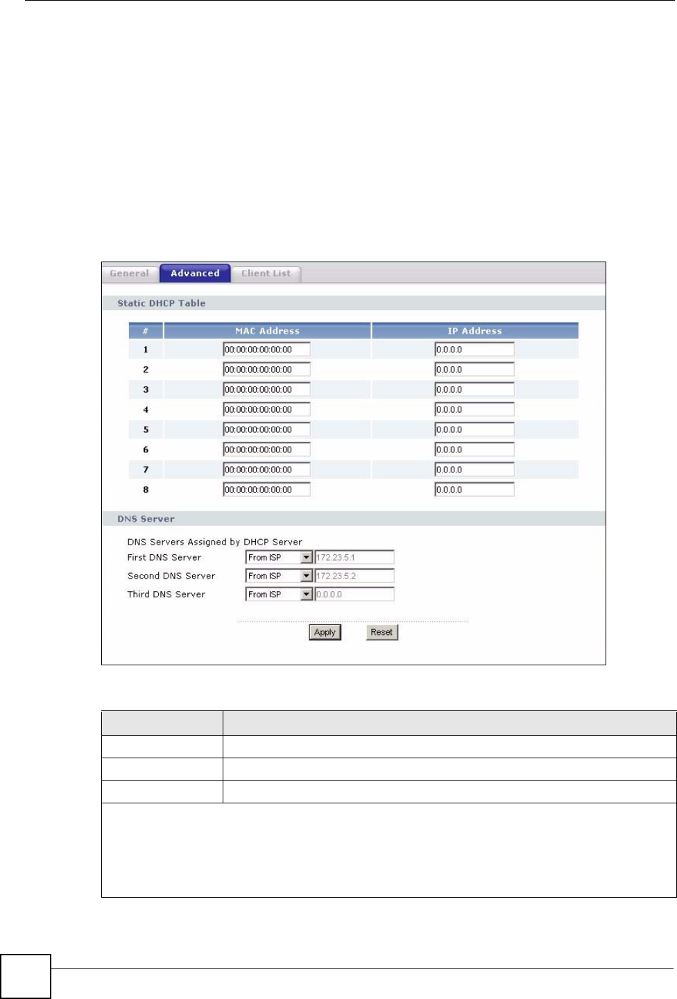
Figure 68 Network > DHCP Server > Advanced
The following table describes the labels in this screen.
Table 43 Network > DHCP Server > Advanced
LABEL DESCRIPTION
# This is the index number of the static IP table entry (row).
MAC Address Type the MAC address (with colons) of a computer on your LAN.
IP Address Type the LAN IP address of a computer on your LAN.
DNS Servers Assigned by DHCP Server
The NBG318S passes a DNS (Domain Name System) server IP address (in the order you specify
here) to the DHCP clients. The NBG318S only passes this information to the LAN DHCP clients when
you select the Enable DHCP Server check box. When you clear the Enable DHCP Server check box,
DHCP service is disabled and you must have another DHCP sever on your LAN, or else the computers
must have their DNS server addresses manually configured.
Chapter 9 DHCP
NBG318S User’s Guide 117
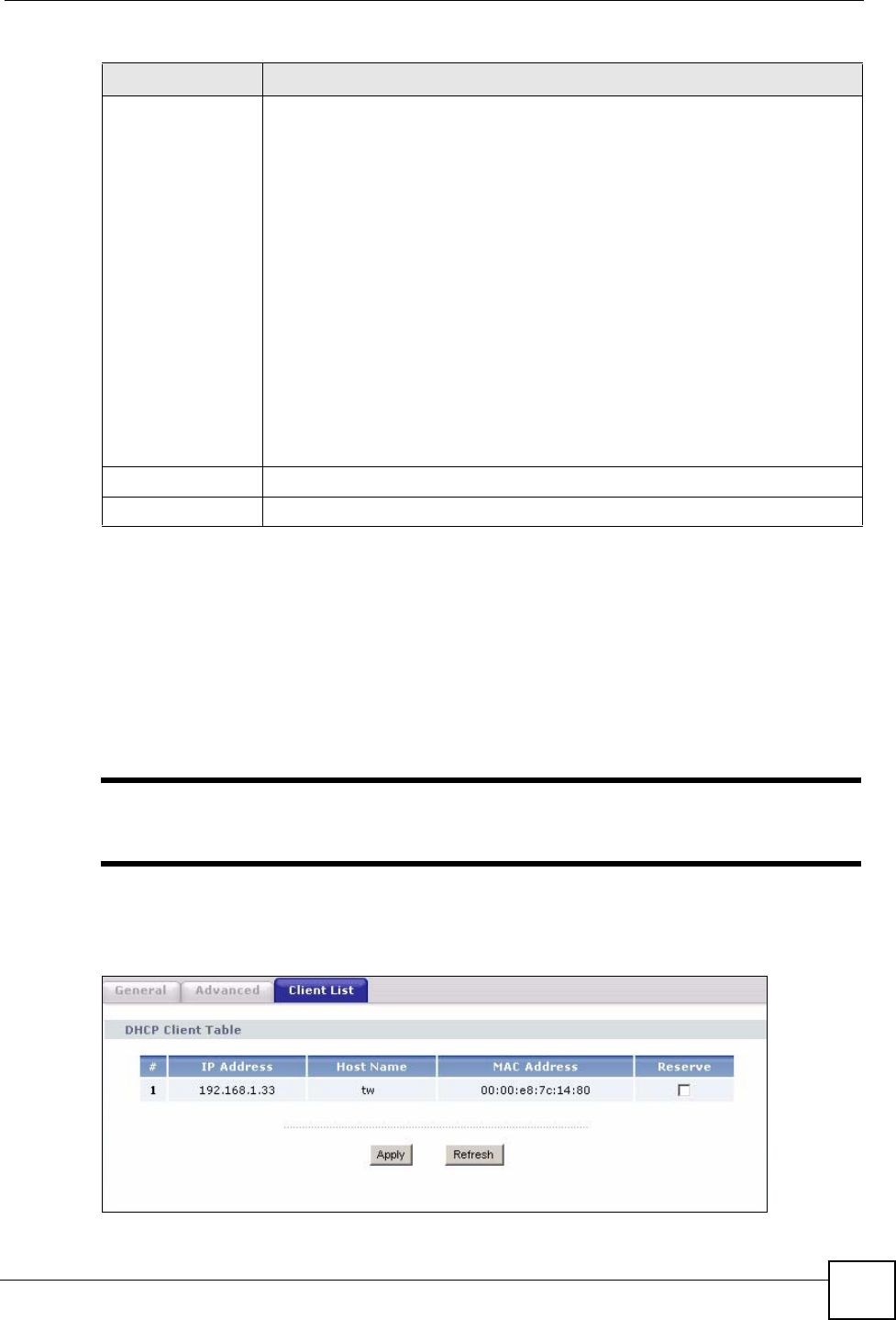
9.4 Client List Screen
The DHCP table shows current DHCP client information (including IP Address, Host Name
and MAC Address) of all network clients using the NBG318S’s DHCP server.
Configure this screen to always assign an IP address to a MAC address (and host name). Click
Network > DHCP Server > Client List.
"You can also view a read-only client list by clicking the DHCP Table
(Details...) hyperlink in the Status screen.
The following screen displays.
Figure 69 Network > DHCP Server > Client List
First DNS Server
Second DNS
Server
Third DNS Server
Select From ISP if your ISP dynamically assigns DNS server information (and
the NBG318S's WAN IP address). The field to the right displays the (read-only)
DNS server IP address that the ISP assigns.
Select User-Defined if you have the IP address of a DNS server. Enter the DNS
server's IP address in the field to the right. If you chose User-Defined, but leave
the IP address set to 0.0.0.0, User-Defined changes to None after you click
Apply. If you set a second choice to User-Defined, and enter the same IP
address, the second User-Defined changes to None after you click Apply.
Select DNS Relay to have the NBG318S act as a DNS proxy. The NBG318S's
LAN IP address displays in the field to the right (read-only). The NBG318S tells
the DHCP clients on the LAN that the NBG318S itself is the DNS server. When a
computer on the LAN sends a DNS query to the NBG318S, the NBG318S
forwards the query to the NBG318S's system DNS server (configured in the
WAN > Internet Connection screen) and relays the response back to the
computer. You can only select DNS Relay for one of the three servers; if you
select DNS Relay for a second or third DNS server, that choice changes to
None after you click Apply.
Select None if you do not want to configure DNS servers. If you do not configure
a DNS server, you must know the IP address of a computer in order to access it.
Apply Click Apply to save your changes back to the NBG318S.
Reset Click Reset to begin configuring this screen afresh.
Table 43 Network > DHCP Server > Advanced
LABEL DESCRIPTION

Chapter 9 DHCP
NBG318S User’s Guide
118
The following table describes the labels in this screen.
Table 44 Network > DHCP Server > Client List
LABEL DESCRIPTION
# This is the index number of the host computer.
IP Address This field displays the IP address relative to the # field listed above.
Host Name This field displays the computer host name.
MAC Address The MAC (Media Access Control) or Ethernet address on a LAN (Local Area
Network) is unique to your computer (six pairs of hexadecimal notation).
A network interface card such as an Ethernet adapter has a hardwired
address that is assigned at the factory. This address follows an industry
standard that ensures no other adapter has a similar address.
Reserve Select this check box to have the NBG318S always assign this IP address to
this MAC address (and host name). After you click Apply, the MAC address
and IP address also display in the Advanced screen (where you can edit
them).
Refresh Click Refresh to reload the DHCP table.

NBG318S User’s Guide 119
CHAPTER 10
Network Address Translation
(NAT)
This chapter discusses how to configure NAT on the NBG318S.
10.1 NAT Overview
NAT (Network Address Translation - NAT, RFC 1631) is the translation of the IP address of a
host in a packet. For example, the source address of an outgoing packet, used within one
network is changed to a different IP address known within another network.
10.2 Using NAT
"You must create a firewall rule in addition to setting up NAT, to allow traffic
from the WAN to be forwarded through the NBG318S.
10.2.1 Port Forwarding: Services and Port Numbers
A port forwarding set is a list of inside (behind NAT on the LAN) servers, for example, web or
FTP, that you can make accessible to the outside world even though NAT makes your whole
inside network appear as a single machine to the outside world.
Use the Application screen to forward incoming service requests to the server(s) on your local
network. You may enter a single port number or a range of port numbers to be forwarded, and
the local IP address of the desired server. The port number identifies a service; for example,
web service is on port 80 and FTP on port 21. In some cases, such as for unknown services or
where one server can support more than one service (for example both FTP and web service),
it might be better to specify a range of port numbers.
In addition to the servers for specified services, NAT supports a default server. A service
request that does not have a server explicitly designated for it is forwarded to the default
server. If the default is not defined, the service request is simply discarded.
Chapter 10 Network Address Translation (NAT)
NBG318S User’s Guide
120
"Many residential broadband ISP accounts do not allow you to run any server
processes (such as a Web or FTP server) from your location. Your ISP may
periodically check for servers and may suspend your account if it discovers
any active services at your location. If you are unsure, refer to your ISP.
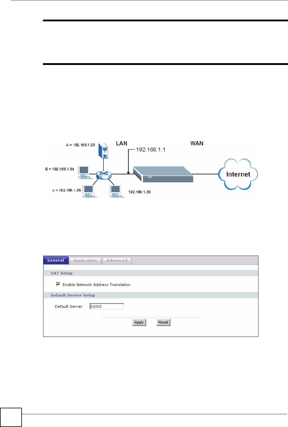
10.2.2 Configuring Servers Behind Port Forwarding Example
Let's say you want to assign ports 21-25 to one FTP, Telnet and SMTP server (A in the
example), port 80 to another (B in the example) and assign a default server IP address of
192.168.1.35 to a third (C in the example). You assign the LAN IP addresses and the ISP
assigns the WAN IP address. The NAT network appears as a single host on the Internet
Figure 70 Multiple Servers Behind NAT Example
10.3 General NAT Screen
Click Network > NAT to open the General screen.
Figure 71 Network > NAT > General

Chapter 10 Network Address Translation (NAT)
NBG318S User’s Guide 121
The following table describes the labels in this screen.
10.4 NAT Application Screen
Port forwarding allows you to define the local servers to which the incoming services will be
forwarded. To change your NBG318S’s port forwarding settings, click Network > NAT >
Application. The screen appears as shown.
"If you do not assign a Default Server IP address in the NAT > General
screen, the NBG318S discards all packets received for ports that are not
specified in this screen or remote management.
Refer to Appendix F on page 271 for port numbers commonly used for particular services.
Table 45 Network > NAT > General
LABEL DESCRIPTION
Enable Network
Address
Translation
Network Address Translation (NAT) allows the translation of an Internet protocol
address used within one network (for example a private IP address used in a local
network) to a different IP address known within another network (for example a
public IP address used on the Internet).
Select the check box to enable NAT.
Default Server
Setup
Default Server In addition to the servers for specified services, NAT supports a default server. A
default server receives packets from ports that are not specified in the Application
screen.
If you do not assign a Default Server IP address, the NBG318S discards all
packets received for ports that are not specified in the Application screen or
remote management.
Apply Click Apply to save your changes back to the NBG318S.
Reset Click Reset to begin configuring this screen afresh.
Chapter 10 Network Address Translation (NAT)
NBG318S User’s Guide
122
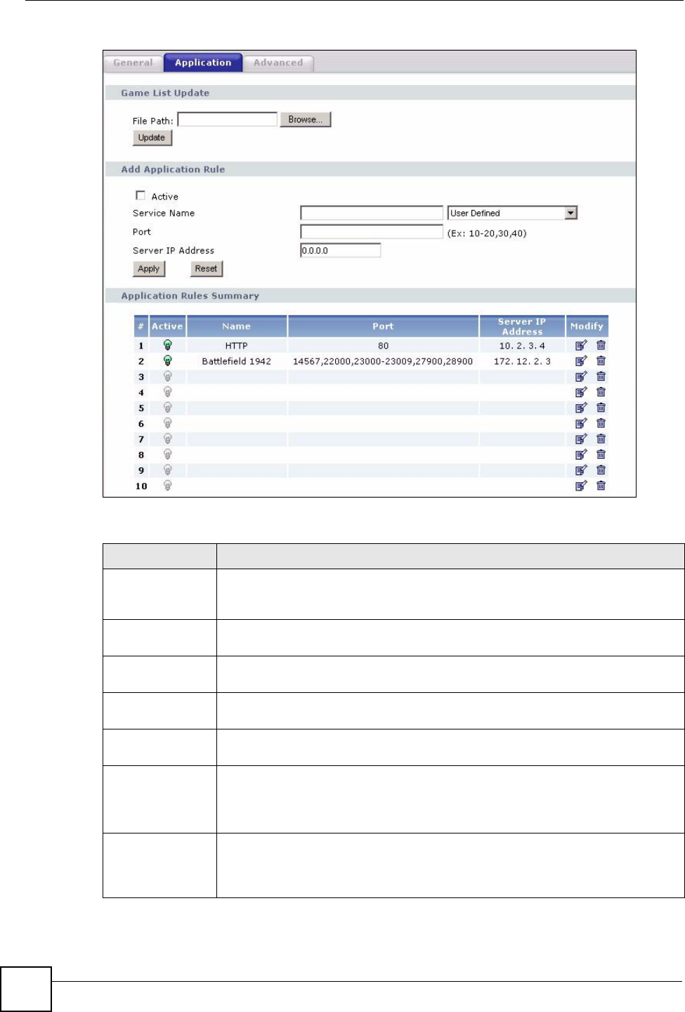
Figure 72 Network > NAT > Application
The following table describes the labels in this screen.
Table 46 NAT Application
LABEL DESCRIPTION
Game List Update A game list includes the pre-defined service name(s) and port number(s). You can
edit and upload it to the NBG318S to replace the existing entries in the second
field next to Service Name.
File Path Type in the location of the file you want to upload in this field or click Browse... to
find it.
Browse... Click Browse... to find the.txt file you want to upload. Remember that you must
decompress compressed (.zip) files before you can upload them.
Update Click Update to begin the upload process. This process may take up to two
minutes.
Add Application
Rule
Active Select the check box to enable this rule and the requested service can be
forwarded to the host with a specified internal IP address.
Clear the checkbox to disallow forwarding of these ports to an inside server
without having to delete the entry.
Service Name Type a name (of up to 31 printable characters) to identify this rule in the first field
next to Service Name. Otherwise, select a predefined service in the second field
next to Service Name. The predefined service name and port number(s) will
display in the Service Name and Port fields.

Chapter 10 Network Address Translation (NAT)
NBG318S User’s Guide 123
10.4.1 Game List Example
Here is an example game list text file. The index number, service name and associated port(s)
are specified by semi-colons (no spaces). Use the name=xxx (where xxx is the service name)
to create a new service. Port range can be separated with a hyphen (-) (no spaces). Multiple
(non-consecutive) ports can be separated by commas.
Port Type a port number(s) to be forwarded.
To specify a range of ports, enter a hyphen (-) between the first port and the last
port, such as 10-20.
To specify two or more non-consecutive port numbers, separate them by a comma
without spaces, such as 123,567.
Server IP Address Type the inside IP address of the server that receives packets from the port(s)
specified in the Port field.
Apply Click Apply to save your changes to the Application Rules Summary table.
Reset Click Reset to not save and return your new changes in the Service Name and
Port fields to the previous one.
Application Rules
Summary
#This is the number of an individual port forwarding server entry.
Active This icon is turned on when the rule is enabled.
Name This field displays a name to identify this rule.
Port This field displays the port number(s).
Server IP Address This field displays the inside IP address of the server.
Modify Click the Edit icon to display and modify an existing rule setting in the fields under
Add Application Rule.
Click the Remove icon to delete a rule.
Table 46 NAT Application (continued)
LABEL DESCRIPTION

Chapter 10 Network Address Translation (NAT)
NBG318S User’s Guide
124
Figure 73 Game List Example
10.5 Trigger Port Forwarding
Some services use a dedicated range of ports on the client side and a dedicated range of ports
on the server side. With regular port forwarding you set a forwarding port in NAT to forward a
service (coming in from the server on the WAN) to the IP address of a computer on the client
side (LAN). The problem is that port forwarding only forwards a service to a single LAN IP
address. In order to use the same service on a different LAN computer, you have to manually
replace the LAN computer's IP address in the forwarding port with another LAN computer's IP
address.
Trigger port forwarding solves this problem by allowing computers on the LAN to
dynamically take turns using the service. The NBG318S records the IP address of a LAN
computer that sends traffic to the WAN to request a service with a specific port number and
protocol (a "trigger" port). When the NBG318S's WAN port receives a response with a
specific port number and protocol ("incoming" port), the NBG318S forwards the traffic to the
LAN IP address of the computer that sent the request. After that computer’s connection for
that service closes, another computer on the LAN can use the service in the same manner. This
way you do not need to configure a new IP address each time you want a different LAN
computer to use the application.
10.5.1 Trigger Port Forwarding Example
The following is an example of trigger port forwarding.
version=1
1;name=Battlefield 1942;port=14567,22000,23000-23009,27900,28900
2;name=Call of Duty;port=28960
3;name=Civilization IV;port=2056
4;name=Diablo I and II;port=6112-6119,4000
5;name=Doom 3;port=27666
6;name=F.E.A.R;port=27888
7;name=Final Fantasy XI;port=25,80,110,443,50000-65535
8;name=Guild Wars;port=6112,80
9;name=Half Life;port=6003,7002,27005,27010,27011,27015
10;name=Jedi Knight III: Jedi Academy;port=28060-28062,28070-28081
11;name=Need for Speed: Hot Pursuit 2;port=1230,8511-
8512,27900,28900,61200-61230
12;name=Neverwinter Nights;port=5120-5300,6500,27900,28900
13;name=Quake 2;port=27910
14;name=Quake 3;port=27660,27960
15;name=Rainbow Six 3: Raven Shield;port=7777-7787,8777-8787
16;name=Serious Sam II;port=25600-25605
17;name=Silent Hunter III;port=17997-18003
18;name=Soldier of Fortune II;port=20100-20112
19;name=Starcraft;port=6112-6119,4000
20;name=Star Trek: Elite Force II;port=29250,29256
21;name=SWAT 4;port=10480-10483
22;name=Warcraft II and III;port=6112-6119,4000
23;name=World of Warcraft;port=3724
Chapter 10 Network Address Translation (NAT)
NBG318S User’s Guide 125
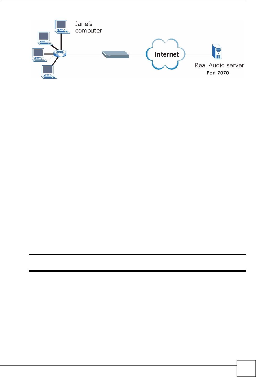
Figure 74 Trigger Port Forwarding Process: Example
1Jane requests a file from the Real Audio server (port 7070).
2Port 7070 is a “trigger” port and causes the NBG318S to record Jane’s computer IP
address. The NBG318S associates Jane's computer IP address with the "incoming" port
range of 6970-7170.
3The Real Audio server responds using a port number ranging between 6970-7170.
4The NBG318S forwards the traffic to Jane’s computer IP address.
5Only Jane can connect to the Real Audio server until the connection is closed or times
out. The NBG318S times out in three minutes with UDP (User Datagram Protocol), or
two hours with TCP/IP (Transfer Control Protocol/Internet Protocol).
10.5.2 Two Points To Remember About Trigger Ports
1Trigger events only happen on data that is going coming from inside the NBG318S and
going to the outside.
2If an application needs a continuous data stream, that port (range) will be tied up so that
another computer on the LAN can’t trigger it.
10.6 NAT Advanced Screen
To change your NBG318S’s trigger port settings, click Network > NAT > Advanced. The
screen appears as shown.
"Only one LAN computer can use a trigger port (range) at a time.
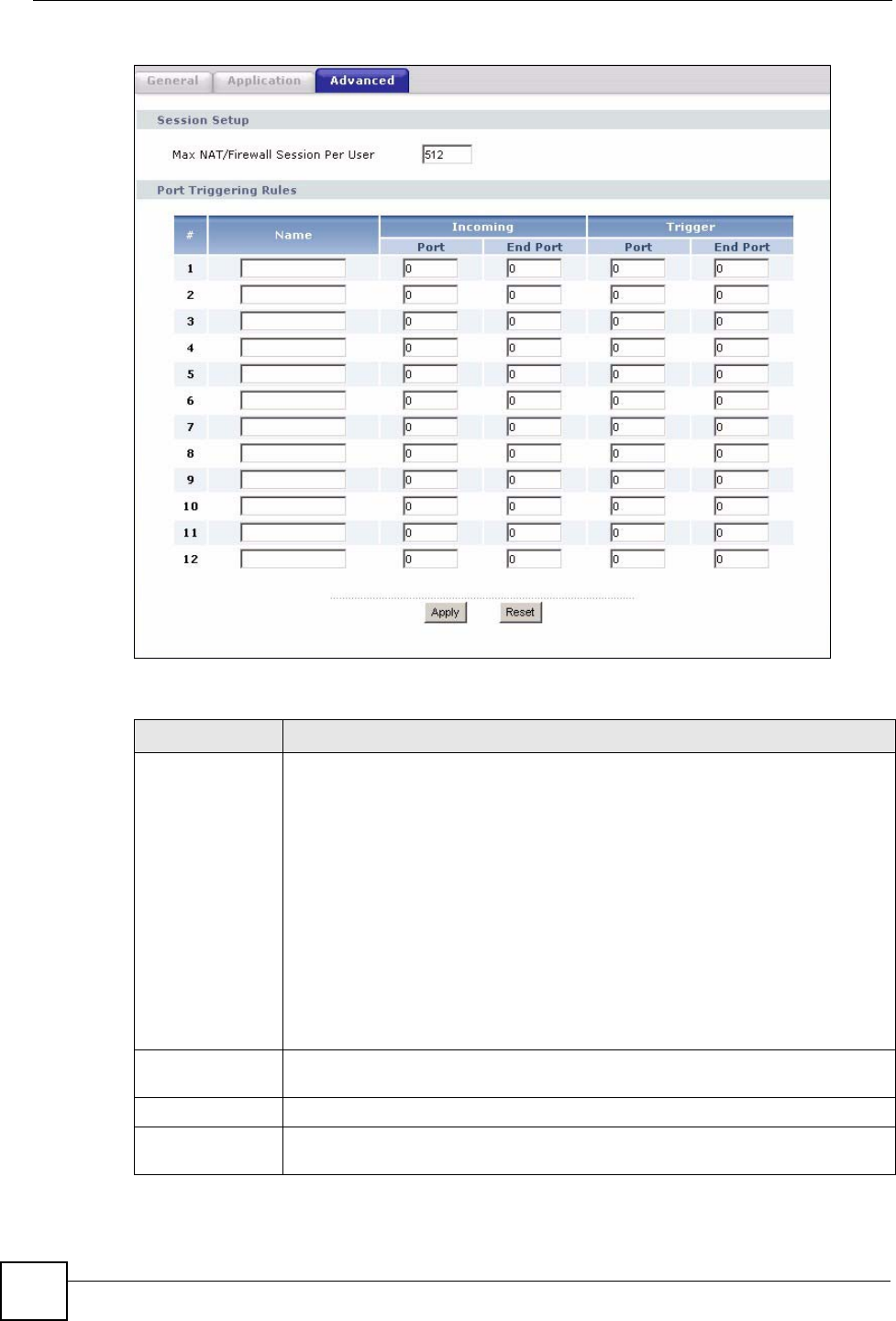
Chapter 10 Network Address Translation (NAT)
NBG318S User’s Guide
126
Figure 75 Network > NAT > Advanced
The following table describes the labels in this screen.
Table 47 Network > NAT > Advanced
LABEL DESCRIPTION
Max NAT/Firewall
Session Per User
Type a number ranging from 1 to 2048 to limit the number of NAT/firewall sessions
that a host can create.
When computers use peer to peer applications, such as file sharing
applications, they may use a large number of NAT sessions. If you do not
limit the number of NAT sessions a single client can establish, this can result in all
of the available NAT sessions being used. In this case, no additional NAT
sessions can be established, and users may not be able to access the Internet.
Each NAT session establishes a corresponding firewall session. Use this field to
limit the number of NAT/firewall sessions each client computer can establish
through the NBG318S.
If your network has a small number of clients using peer to peer applications, you
can raise this number to ensure that their performance is not degraded by the
number of NAT sessions they can establish. If your network has a large number of
users using peer to peer applications, you can lower this number to ensure no
single client is using all of the available NAT sessions.
Port Triggering
Rules
#This is the rule index number (read-only).
Name Type a unique name (up to 15 characters) for identification purposes. All
characters are permitted - including spaces.

Chapter 10 Network Address Translation (NAT)
NBG318S User’s Guide 127
Incoming Incoming is a port (or a range of ports) that a server on the WAN uses when it
sends out a particular service. The NBG318S forwards the traffic with this port (or
range of ports) to the client computer on the LAN that requested the service.
Start Port Type a port number or the starting port number in a range of port numbers.
End Port Type a port number or the ending port number in a range of port numbers.
Trigger The trigger port is a port (or a range of ports) that causes (or triggers) the
NBG318S to record the IP address of the LAN computer that sent the traffic to a
server on the WAN.
Start Port Type a port number or the starting port number in a range of port numbers.
End Port Type a port number or the ending port number in a range of port numbers.
Apply Click Apply to save your changes back to the NBG318S.
Reset Click Reset to begin configuring this screen afresh.
Table 47 Network > NAT > Advanced
LABEL DESCRIPTION

Chapter 10 Network Address Translation (NAT)
NBG318S User’s Guide
128

NBG318S User’s Guide 129
CHAPTER 11
Dynamic DNS
11.1 Dynamic DNS Introduction
Dynamic DNS allows you to update your current dynamic IP address with one or many
dynamic DNS services so that anyone can contact you (in NetMeeting, CU-SeeMe, etc.). You
can also access your FTP server or Web site on your own computer using a domain name (for
instance myhost.dhs.org, where myhost is a name of your choice) that will never change
instead of using an IP address that changes each time you reconnect. Your friends or relatives
will always be able to call you even if they don't know your IP address.
First of all, you need to have registered a dynamic DNS account with www.dyndns.org. This is
for people with a dynamic IP from their ISP or DHCP server that would still like to have a
domain name. The Dynamic DNS service provider will give you a password or key.
11.1.1 DynDNS Wildcard
Enabling the wildcard feature for your host causes *.yourhost.dyndns.org to be aliased to the
same IP address as yourhost.dyndns.org. This feature is useful if you want to be able to use,
for example, www.yourhost.dyndns.org and still reach your hostname.
"If you have a private WAN IP address, then you cannot use Dynamic DNS.
11.2 Dynamic DNS Screen
To change your NBG318S’s DDNS, click Network > DDNS. The screen appears as shown.
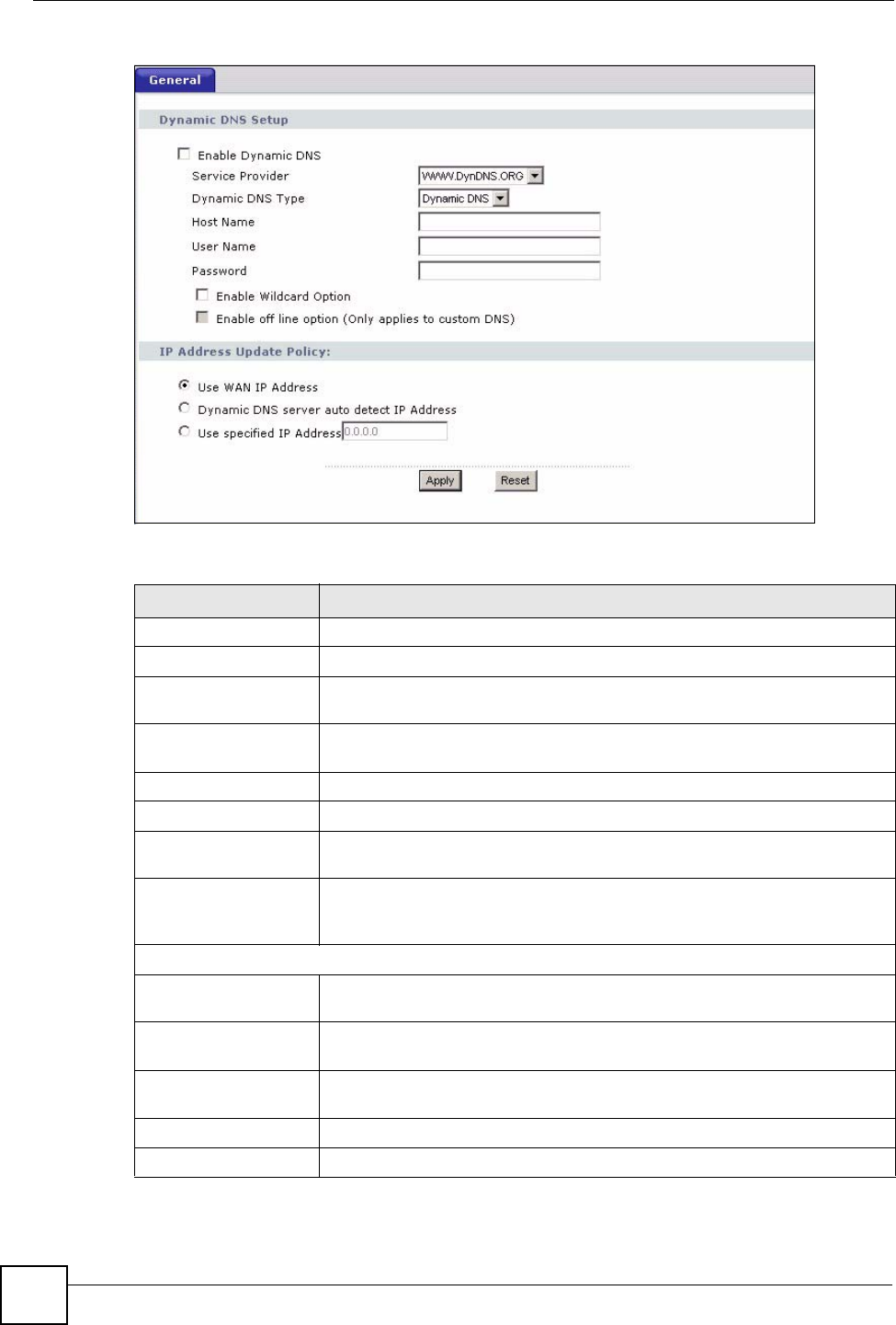
Chapter 11 Dynamic DNS
NBG318S User’s Guide
130
Figure 76 Dynamic DNS
The following table describes the labels in this screen.
Table 48 Dynamic DNS
LABEL DESCRIPTION
Enable Dynamic DNS Select this check box to use dynamic DNS.
Service Provider Select the name of your Dynamic DNS service provider.
Dynamic DNS Type Select the type of service that you are registered for from your Dynamic DNS
service provider.
Host Name Enter a host names in the field provided. You can specify up to two host
names in the field separated by a comma (",").
User Name Enter your user name.
Password Enter the password assigned to you.
Enable Wildcard
Option
Select the check box to enable DynDNS Wildcard.
Enable off line option This option is available when CustomDNS is selected in the DDNS Type
field. Check with your Dynamic DNS service provider to have traffic
redirected to a URL (that you can specify) while you are off line.
IP Address Update Policy:
Use WAN IP Address Select this option to update the IP address of the host name(s) to the WAN IP
address.
Dynamic DNS server
auto detect IP Address
Select this option to update the IP address of the host name(s) automatically
by the DDNS server. It is recommended that you select this option.
Use specified IP
Address
Type the IP address of the host name(s). Use this if you have a static IP
address.
Apply Click Apply to save your changes back to the NBG318S.
Reset Click Reset to begin configuring this screen afresh.

Chapter 11 Dynamic DNS
NBG318S User’s Guide 131

Chapter 11 Dynamic DNS
NBG318S User’s Guide
132

133
PART III
Security
Firewall (135)
Content Filtering (141)

134

NBG318S User’s Guide 135
CHAPTER 12
Firewall
This chapter gives some background information on firewalls and explains how to get started
with the NBG318S’s firewall.
12.1 Introduction to ZyXEL’s Firewall
12.1.1 What is a Firewall?
Originally, the term “firewall” referred to a construction technique designed to prevent the
spread of fire from one room to another. The networking term "firewall" is a system or group
of systems that enforces an access-control policy between two networks. It may also be
defined as a mechanism used to protect a trusted network from a network that is not trusted. Of
course, firewalls cannot solve every security problem. A firewall is one of the mechanisms
used to establish a network security perimeter in support of a network security policy. It
should never be the only mechanism or method employed. For a firewall to guard effectively,
you must design and deploy it appropriately. This requires integrating the firewall into a broad
information-security policy. In addition, specific policies must be implemented within the
firewall itself.
12.1.2 Stateful Inspection Firewall
Stateful inspection firewalls restrict access by screening data packets against defined access
rules. They make access control decisions based on IP address and protocol. They also
"inspect" the session data to assure the integrity of the connection and to adapt to dynamic
protocols. These firewalls generally provide the best speed and transparency; however, they
may lack the granular application level access control or caching that some proxies support.
Firewalls, of one type or another, have become an integral part of standard security solutions
for enterprises.
12.1.3 About the NBG318S Firewall
The NBG318S firewall is a stateful inspection firewall and is designed to protect against
Denial of Service attacks when activated (click the General tab under Firewall and then click
the Enable Firewall check box). The NBG318S's purpose is to allow a private Local Area
Network (LAN) to be securely connected to the Internet. The NBG318S can be used to
prevent theft, destruction and modification of data, as well as log events, which may be
important to the security of your network.

Chapter 12 Firewall
NBG318S User’s Guide
136
The NBG318S is installed between the LAN and a broadband modem connecting to the
Internet. This allows it to act as a secure gateway for all data passing between the Internet and
the LAN.
The NBG318S has one Ethernet WAN port and four Ethernet LAN ports, which are used to
physically separate the network into two areas.The WAN (Wide Area Network) port attaches
to the broadband (cable or DSL) modem to the Internet.
The LAN (Local Area Network) port attaches to a network of computers, which needs security
from the outside world. These computers will have access to Internet services such as e-mail,
FTP and the World Wide Web. However, "inbound access" is not allowed (by default) unless
the remote host is authorized to use a specific service.
12.1.4 Guidelines For Enhancing Security With Your Firewall
1Change the default password via web configurator.
2Think about access control before you connect to the network in any way, including
attaching a modem to the port.
3Limit who can access your router.
4Don't enable any local service (such as SNMP or NTP) that you don't use. Any enabled
service could present a potential security risk. A determined hacker might be able to find
creative ways to misuse the enabled services to access the firewall or the network.
5For local services that are enabled, protect against misuse. Protect by configuring the
services to communicate only with specific peers, and protect by configuring rules to
block packets for the services at specific interfaces.
6Protect against IP spoofing by making sure the firewall is active.
7Keep the firewall in a secured (locked) room.
12.2 Triangle Routes
If an alternate gateway on the LAN has an IP address in the same subnet as the NBG318S’s
LAN IP address, return traffic may not go through the NBG318S. This is called an
asymmetrical or “triangle” route. This causes the NBG318S to reset the connection, as the
connection has not been acknowledged.
You can have the NBG318S permit the use of asymmetrical route topology on the network
(not reset the connection).
Allowing asymmetrical routes may let traffic from the WAN go directly to the LAN without
passing through the NBG318S. A better solution is to use IP alias to put the NBG318S and the
backup gateway on separate subnets.
12.2.1 Triangle Routes and IP Alias
You can use IP alias instead of allowing triangle routes. IP Alias allow you to partition your
network into logical sections over the same interface.
By putting your LAN and Gateway A in different subnets, all returning network traffic must
pass through the NBG318S to your LAN. The following steps describe such a scenario.
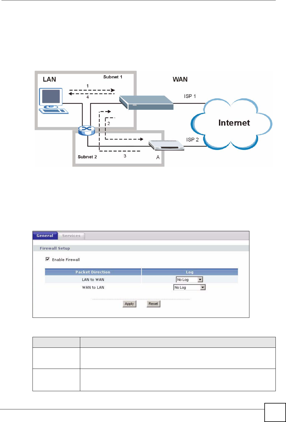
Chapter 12 Firewall
NBG318S User’s Guide 137
1A computer on the LAN initiates a connection by sending a SYN packet to a receiving
server on the WAN.
2The NBG318S reroutes the packet to Gateway A, which is in Subnet 2.
3The reply from the WAN goes to the NBG318S.
4The NBG318S then sends it to the computer on the LAN in Subnet 1.
Figure 77 Using IP Alias to Solve the Triangle Route Problem
12.3 General Firewall Screen
Click Security > Firewall to open the General screen. Use this screen to enable or disable the
NBG318S’s firewall, and set up firewall logs.
Figure 78 Security > Firewall > General l
The following table describes the labels in this screen.
Table 49 Security > Firewall > General
LABEL DESCRIPTION
Enable Firewall Select this check box to activate the firewall. The NBG318S performs access
control and protects against Denial of Service (DoS) attacks when the firewall is
activated.
Packet Direction This is the direction of travel of packets.
Firewall rules are grouped based on the direction of travel of packets to which they
apply.

Chapter 12 Firewall
NBG318S User’s Guide
138
12.4 Services Screen
Click Security > Firewall > Services. The screen appears as shown next.
If an outside user attempts to probe an unsupported port on your NBG318S, an ICMP response
packet is automatically returned. This allows the outside user to know the NBG318S exists.
Use this screen to prevent the ICMP response packet from being sent. This keeps outsiders
from discovering your NBG318S when unsupported ports are probed.
You can also use this screen to enable service blocking, enter/delete/modify the services you
want to block and the date/time you want to block them.
Log Select whether to create a log for packets that are traveling in the selected
direction when the packets are blocked or forwarded.
To log packets related to firewall rules, make sure that Access Control under Log
is selected in the Logs > Log Settings screen.
Apply Click Apply to save the settings.
Reset Click Reset to start configuring this screen again.
Table 49 Security > Firewall > General
LABEL DESCRIPTION
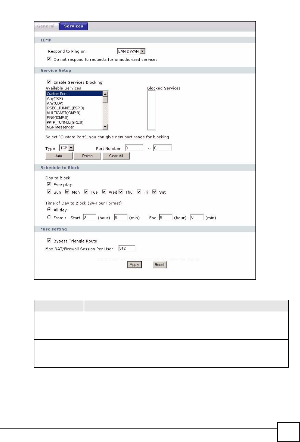
Chapter 12 Firewall
NBG318S User’s Guide 139
Figure 79 Security > Firewall > Services
The following table describes the labels in this screen.
Table 50 Security > Firewall > Services
LABEL DESCRIPTION
ICMP Internet Control Message Protocol is a message control and error-reporting
protocol between a host server and a gateway to the Internet. ICMP uses Internet
Protocol (IP) datagrams, but the messages are processed by the TCP/IP software
and directly apparent to the application user.
Respond to Ping
on
The NBG318S will not respond to any incoming Ping requests when Disable is
selected. Select LAN to reply to incoming LAN Ping requests. Select WAN to reply
to incoming WAN Ping requests. Otherwise select LAN & WAN to reply to both
incoming LAN and WAN Ping requests.

Chapter 12 Firewall
NBG318S User’s Guide
140
Do not respond to
requests for
unauthorized
services
Select this option to prevent hackers from finding the NBG318S by probing for
unused ports. If you select this option, the NBG318S will not respond to port
request(s) for unused ports, thus leaving the unused ports and the NBG318S
unseen. By default this option is not selected and the NBG318S will reply with an
ICMP Port Unreachable packet for a port probe on its unused UDP ports, and a
TCP Reset packet for a port probe on its unused TCP ports.
Note that the probing packets must first traverse the NBG318S's firewall
mechanism before reaching this anti-probing mechanism. Therefore if the firewall
mechanism blocks a probing packet, the NBG318S reacts based on the firewall
policy, which by default, is to send a TCP reset packet for a blocked TCP packet.
You can use the command "sys firewall tcprst rst [on|off]" to change this policy.
When the firewall mechanism blocks a UDP packet, it drops the packet without
sending a response packet.
Service Setup
Enable Services
Blocking
Select this check box to enable this feature.
Available
Services
This is a list of pre-defined services (ports) you may prohibit your LAN computers
from using. Select the port you want to block using the drop-down list and click
Add to add the port to the Blocked Services field.
Blocked Services This is a list of services (ports) that will be inaccessible to computers on your LAN
once you enable service blocking.
Custom Port A custom port is a service that is not available in the pre-defined Available
Services list and you must define using the next two fields.
Type Choose the IP port (TCP or UDP) that defines your customized port from the drop
down list box.
Port Number Enter the port number range that defines the service. For example, if you want to
define the Gnutella service, then select TCP type and enter a port range from
6345 to 6349.
Add Select a service from the Available Services drop-down list and then click Add to
add a service to the Blocked Services
Delete Select a service from the Blocked Services list and then click Delete to remove
this service from the list.
Clear All Click Clear All to empty the Blocked Services.
Schedule to Block
Day to Block: Select a check box to configure which days of the week (or everyday) you want
service blocking to be active.
Time of Day to
Block (24-Hour
Format)
Select the time of day you want service blocking to take effect. Configure blocking
to take effect all day by selecting All Day. You can also configure specific times by
selecting From and entering the start time in the Start (hour) and Start (min)
fields and the end time in the End (hour) and End (min) fields. Enter times in 24-
hour format, for example, "3:00pm" should be entered as "15:00".
Misc setting
Bypass Triangle
Route
Select this check box to have the NBG318S firewall ignore the use of triangle
route topology on the network.
Max NAT/Firewall
Session Per User
Type a number ranging from 1 to 2048 to limit the number of NAT/firewall sessions
that a host can create.
Apply Click Apply to save the settings.
Reset Click Reset to start configuring this screen again.
Table 50 Security > Firewall > Services
LABEL DESCRIPTION

NBG318S User’s Guide 141
CHAPTER 13
Content Filtering
This chapter provides a brief overview of content filtering using the embedded web GUI.
13.1 Introduction to Content Filtering
Internet content filtering allows you to create and enforce Internet access policies tailored to
your needs. Content filtering is the ability to block certain web features or specific URL
keywords.
13.2 Restrict Web Features
The NBG318S can block web features such as ActiveX controls, Java applets, cookies and
disable web proxies.
13.3 Days and Times
The NBG318S also allows you to define time periods and days during which the NBG318S
performs content filtering.
13.4 Filter Screen
Click Security > Content Filter to open the Filter screen.
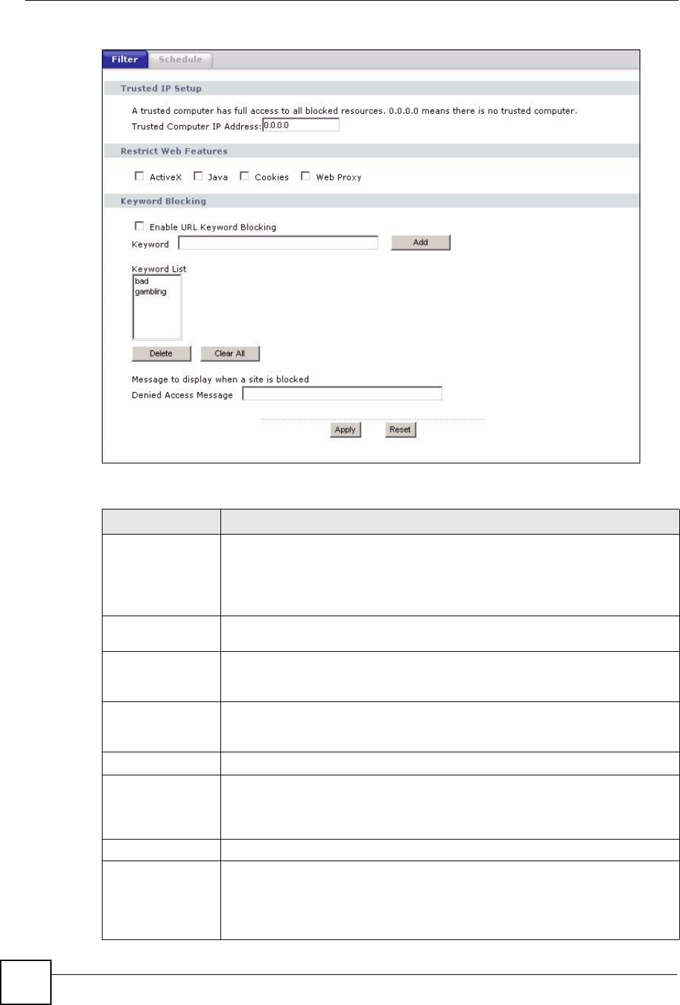
Chapter 13 Content Filtering
NBG318S User’s Guide
142
Figure 80 Security > Content Filter > Filter
The following table describes the labels in this screen.
Table 51 Security > Content Filter > Filter
LABEL DESCRIPTION
Trusted Computer
IP Address
To enable this feature, type an IP address of any one of the computers in your
network that you want to have as a trusted computer. This allows the trusted
computer to have full access to all features that are configured to be blocked by
content filtering.
Leave this field blank to have no trusted computers.
Restrict Web
Features
Select the box(es) to restrict a feature. When you download a page containing a
restricted feature, that part of the web page will appear blank or grayed out.
ActiveX A tool for building dynamic and active Web pages and distributed object
applications. When you visit an ActiveX Web site, ActiveX controls are
downloaded to your browser, where they remain in case you visit the site again.
Java A programming language and development environment for building
downloadable Web components or Internet and intranet business applications of
all kinds.
Cookies Used by Web servers to track usage and provide service based on ID.
Web Proxy A server that acts as an intermediary between a user and the Internet to provide
security, administrative control, and caching service. When a proxy server is
located on the WAN it is possible for LAN users to circumvent content filtering by
pointing to this proxy server.
Keyword Blocking
Enable URL
Keyword Blocking
The NBG318S can block Web sites with URLs that contain certain keywords in
the domain name or IP address. For example, if the keyword "bad" was enabled,
all sites containing this keyword in the domain name or IP address will be
blocked, e.g., URL http://www.website.com/bad.html would be blocked. Select
this check box to enable this feature.
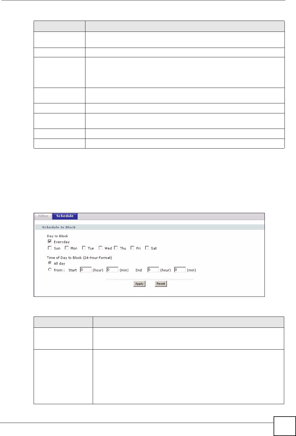
Chapter 13 Content Filtering
NBG318S User’s Guide 143
13.5 Schedule
Use this screen to set the day(s) and time you want the NBG318S to use content filtering.
Click Security > Content Filter > Schedule. The following screen displays.
Figure 81 Security > Content Filter > Schedule
The following table describes the labels in this screen.
Keyword Type a keyword in this field. You may use any character (up to 64 characters).
Wildcards are not allowed. You can also enter a numerical IP address.
Keyword List This list displays the keywords already added.
Add Click Add after you have typed a keyword.
Repeat this procedure to add other keywords. Up to 64 keywords are allowed.
When you try to access a web page containing a keyword, you will get a
message telling you that the content filter is blocking this request.
Delete Highlight a keyword in the lower box and click Delete to remove it. The keyword
disappears from the text box after you click Apply.
Clear All Click this button to remove all of the listed keywords.
Denied Access
Message
Enter a message to be displayed when a user tries to access a restricted web
site. The default message is “Please contact your network administrator!!”
Apply Click Apply to save your changes.
Reset Click Reset to begin configuring this screen afresh
Table 51 Security > Content Filter > Filter
LABEL DESCRIPTION
Table 52 Security > Content Filter > Schedule
LABEL DESCRIPTION
Day to Block Select check boxes for the days that you want the NBG318S to perform
content filtering. Select the Everyday check box to have content filtering
turned on all days of the week.
Time of Day to Block
(24-Hour Format)
Time of Day to Block allows the administrator to define during which time
periods content filtering is enabled. Time of Day to Block restrictions only
apply to the keywords (see above). Restrict web server data, such as ActiveX,
Java, Cookies and Web Proxy are not affected.
Select All Day to have content filtering always active on the days selected in
Day to Block with time of day limitations not enforced.
Select From and enter the time period, in 24-hour format, during which
content filtering will be enforced.

Chapter 13 Content Filtering
NBG318S User’s Guide
144
13.6 Customizing Keyword Blocking URL Checking
You can use commands to set how much of a website’s URL the content filter is to check for
keyword blocking. See the appendices for information on how to access and use the command
interpreter.
13.6.1 Domain Name or IP Address URL Checking
By default, the NBG318S checks the URL’s domain name or IP address when performing
keyword blocking.
This means that the NBG318S checks the characters that come before the first slash in the
URL.
For example, with the URL www.zyxel.com.tw/news/pressroom.php, content filtering only
searches for keywords within www.zyxel.com.tw.
13.6.2 Full Path URL Checking
Full path URL checking has the NBG318S check the characters that come before the last slash
in the URL.
For example, with the URL www.zyxel.com.tw/news/pressroom.php, full path URL checking
searches for keywords within www.zyxel.com.tw/news/.
Use the ip urlfilter customize actionFlags 6 [disable | enable]
command to extend (or not extend) the keyword blocking search to include the URL's full
path.
13.6.3 File Name URL Checking
Filename URL checking has the NBG318S check all of the characters in the URL.
For example, filename URL checking searches for keywords within the URL
www.zyxel.com.tw/news/pressroom.php.
Use the ip urlfilter customize actionFlags 8 [disable | enable]
command to extend (or not extend) the keyword blocking search to include the URL's
complete filename.
Apply Click Apply to save your customized settings and exit this screen.
Reset Click Reset to begin configuring this screen afresh
Table 52 Security > Content Filter > Schedule
LABEL DESCRIPTION

Chapter 13 Content Filtering
NBG318S User’s Guide 145

Chapter 13 Content Filtering
NBG318S User’s Guide
146

147
PART IV
Management
Static Route Screens (149)
Bandwidth Management (153)
Remote Management (165)
Universal Plug-and-Play (UPnP) (171)

148
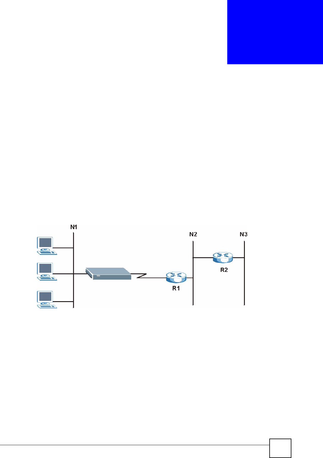
NBG318S User’s Guide 149
CHAPTER 14
Static Route Screens
This chapter shows you how to configure static routes for your NBG318S.
14.1 Static Route Overview
Each remote node specifies only the network to which the gateway is directly connected, and
the NBG318S has no knowledge of the networks beyond. For instance, the NBG318S knows
about network N2 in the following figure through remote node router R1. However, the
NBG318S is unable to route a packet to network N3 because it doesn't know that there is a
route through the same remote node router R1 (via gateway router R2). The static routes are
for you to tell the NBG318S about the networks beyond the remote nodes.
Figure 82 Example of Static Routing Topology
14.2 IP Static Route Screen
Click Management > Static Route to open the IP Static Route screen. The following screen
displays.
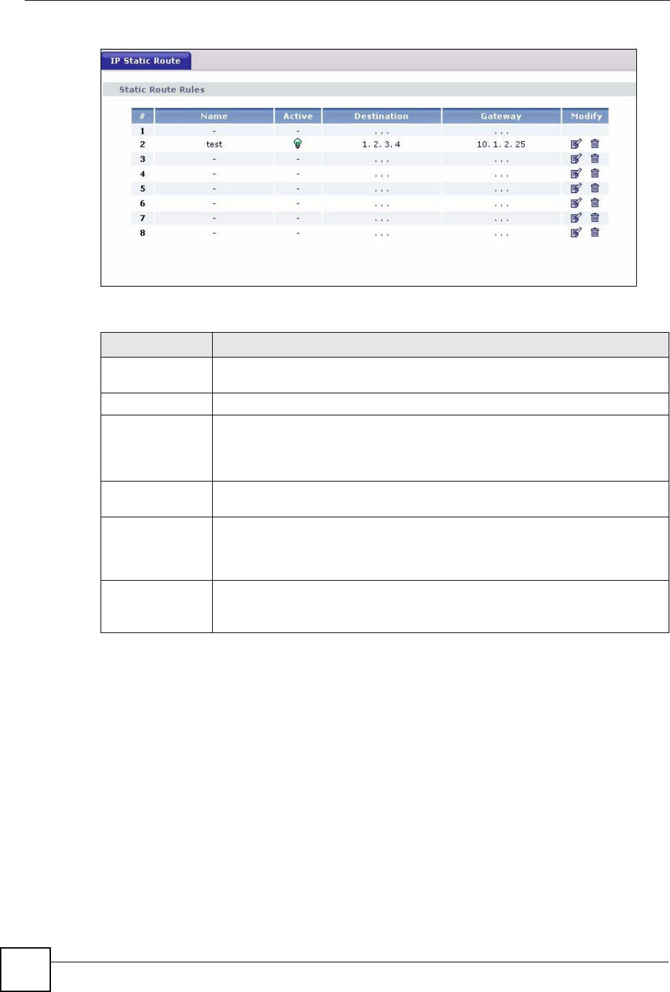
Chapter 14 Static Route Screens
NBG318S User’s Guide
150
Figure 83 Management > Static Route > IP Static Route
The following table describes the labels in this screen.
14.2.1 Static Route Setup Screen
To edit a static route, click the edit icon under Modify. The following screen displays. Fill in
the required information for each static route.
Table 53 Management > Static Route > IP Static Route
LABEL DESCRIPTION
#This is the index number of an individual static route. The first entry is for the
default route and not editable.
Name This is the name that describes or identifies this route.
Active This icon is turned on when this static route is active.
Click the Edit icon under Modify and select the Active checkbox in the Static
Route Setup screen to enable the static route. Clear the checkbox to disable this
static route without having to delete the entry.
Destination This parameter specifies the IP network address of the final destination. Routing
is always based on network number.
Gateway This is the IP address of the gateway. The gateway is an immediate neighbor of
your NBG318S that will forward the packet to the destination. On the LAN, the
gateway must be a router on the same segment as your NBG318S; over the
WAN, the gateway must be the IP address of one of the remote nodes.
Modify Click the Edit icon to open the static route setup screen. Modify a static route or
create a new static route in the Static Route Setup screen.
Click the Remove icon to delete a static route.
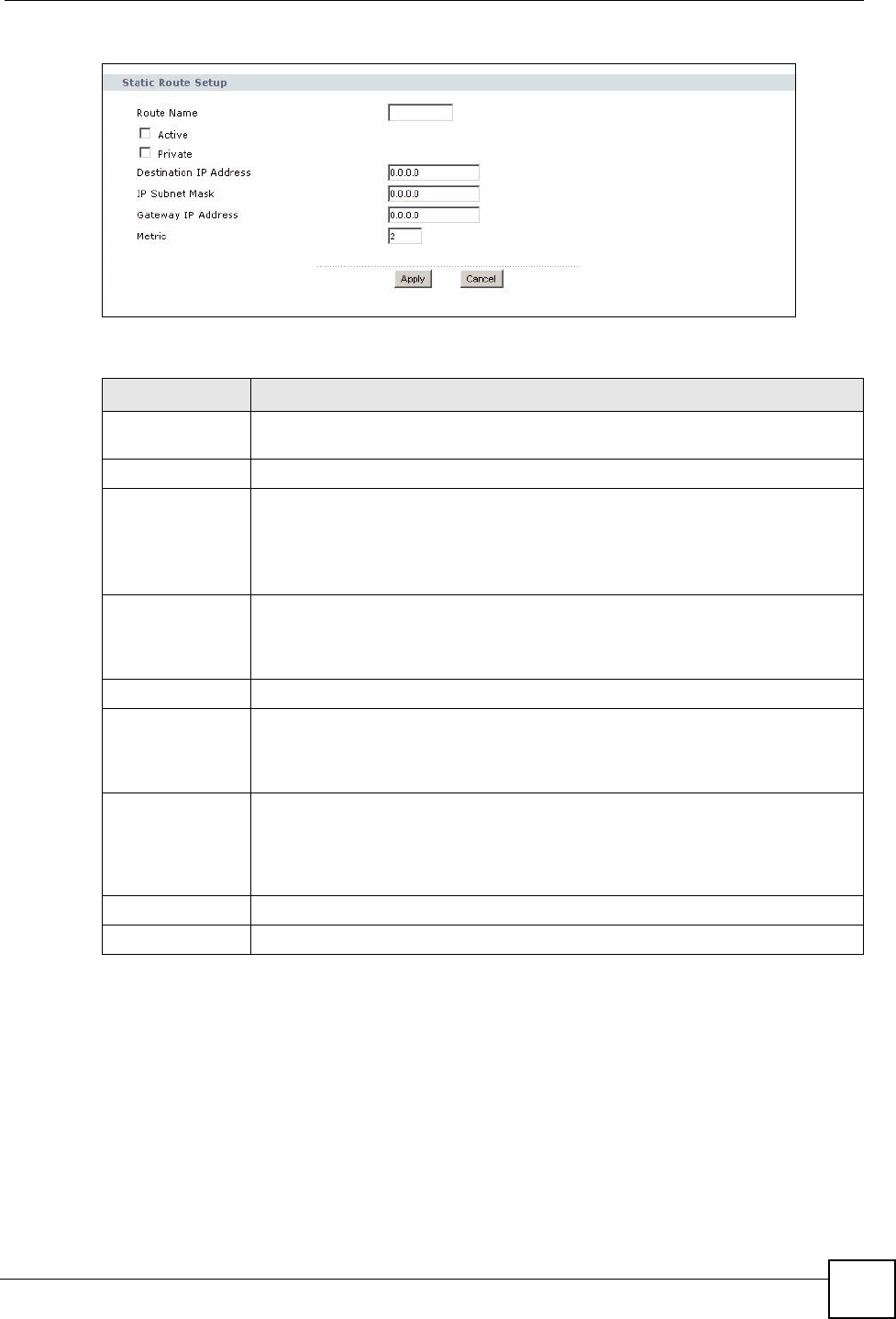
Chapter 14 Static Route Screens
NBG318S User’s Guide 151
Figure 84 Management > Static Route > IP Static Route: Static Route Setup
The following table describes the labels in this screen.
Table 54 Management > Static Route > IP Static Route: Static Route Setup
LABEL DESCRIPTION
Route Name Enter the name of the IP static route. Leave this field blank to delete this static
route.
Active This field allows you to activate/deactivate this static route.
Private This parameter determines if the NBG318S will include this route to a remote node
in its RIP broadcasts.
Select this check box to keep this route private and not included in RIP
broadcasts. Clear this checkbox to propagate this route to other hosts through RIP
broadcasts.
Destination IP
Address
This parameter specifies the IP network address of the final destination. Routing is
always based on network number. If you need to specify a route to a single host,
use a subnet mask of 255.255.255.255 in the subnet mask field to force the
network number to be identical to the host ID.
IP Subnet Mask Enter the IP subnet mask here.
Gateway IP
Address
Enter the IP address of the gateway. The gateway is an immediate neighbor of
your NBG318S that will forward the packet to the destination. On the LAN, the
gateway must be a router on the same segment as your NBG318S; over the WAN,
the gateway must be the IP address of one of the Remote Nodes.
Metric Metric represents the “cost” of transmission for routing purposes. IP routing uses
hop count as the measurement of cost, with a minimum of 1 for directly connected
networks. Enter a number that approximates the cost for this link. The number
need not be precise, but it must be between 1 and 15. In practice, 2 or 3 is usually
a good number.
Apply Click Apply to save your changes back to the NBG318S.
Cancel Click Cancel to return to the previous screen and not save your changes.

Chapter 14 Static Route Screens
NBG318S User’s Guide
152

NBG318S User’s Guide 153
CHAPTER 15
Bandwidth Management
This chapter contains information about configuring bandwidth management, editing rules and
viewing the NBG318S’s bandwidth management logs.
15.1 Bandwidth Management Overview
ZyXEL’s Bandwidth Management allows you to specify bandwidth management rules based
on an application and/or subnet. You can allocate specific amounts of bandwidth capacity
(bandwidth budgets) to different bandwidth rules.
The NBG318S applies bandwidth management to traffic that it forwards out through an
interface. The NBG318S does not control the bandwidth of traffic that comes into an interface.
Bandwidth management applies to all traffic flowing out of the router, regardless of the
traffic's source.
Traffic redirect or IP alias may cause LAN-to-LAN traffic to pass through the NBG318S and
be managed by bandwidth management.
• The sum of the bandwidth allotments that apply to the WAN interface (LAN to WAN,
WLAN to WAN, WAN to WAN / NBG318S) must be less than or equal to the Upstream
Bandwidth that you configure in the Bandwidth Management Advanced screen.
• The sum of the bandwidth allotments that apply to the LAN port (WAN to LAN, WLAN
to LAN, LAN to LAN / NBG318S) must be less than or equal to 100,000 kbps (you
cannot configure the bandwidth budget for the LAN port).
• The sum of the bandwidth allotments that apply to the WLAN port (LAN to WLAN,
WAN to WLAN, WLAN to WLAN / NBG318S) must be less than or equal to 54,000
kbps (you cannot configure the bandwidth budget for the WLAN port).
15.2 Application-based Bandwidth Management
You can create bandwidth classes based on individual applications (like VoIP, Web, FTP, E-
mail and Video for example).
15.3 Subnet-based Bandwidth Management
You can create bandwidth classes based on subnets.
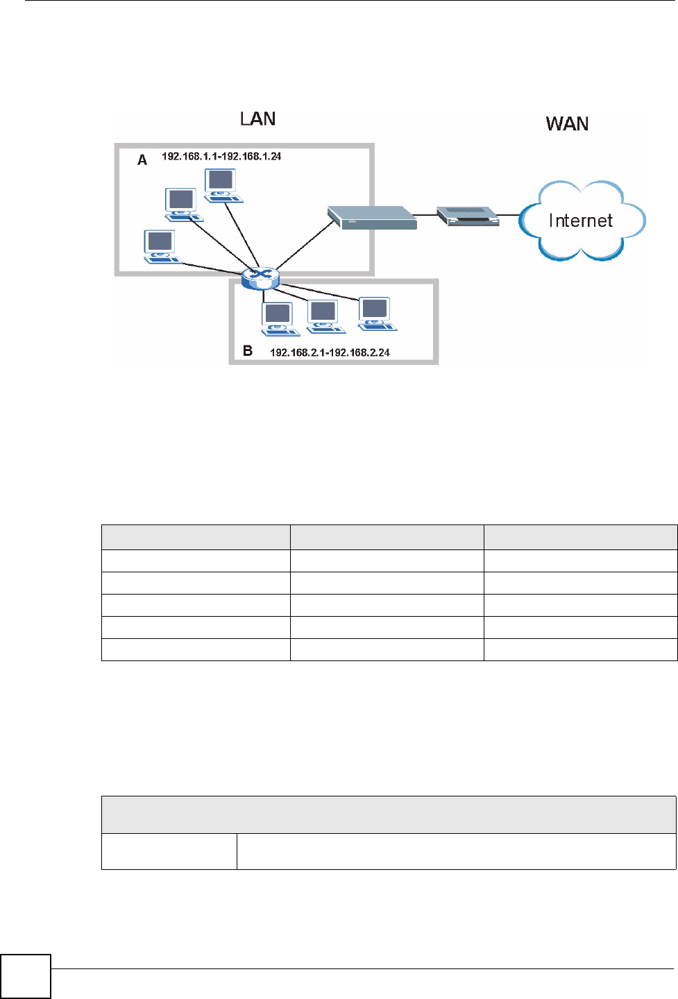
Chapter 15 Bandwidth Management
NBG318S User’s Guide
154
The following figure shows LAN subnets. You could configure one bandwidth class for
subnet A and another for subnet B.
Figure 85 Subnet-based Bandwidth Management Example
15.4 Application and Subnet-based Bandwidth Management
You could also create bandwidth classes based on a combination of a subnet and an
application. The following example table shows bandwidth allocations for application specific
traffic from separate LAN subnets.
15.5 Bandwidth Management Priorities
The following table describes the priorities that you can apply to traffic that the NBG318S
forwards out through an interface.
Table 55 Application and Subnet-based Bandwidth Management Example
TRAFFIC TYPE FROM SUBNET A FROM SUBNET B
VoIP 64 Kbps 64 Kbps
Web 64 Kbps 64 Kbps
FTP 64 Kbps 64 Kbps
E-mail 64 Kbps 64 Kbps
Video 64 Kbps 64 Kbps
Table 56 Bandwidth Management Priorities
PRIORITY LEVELS: TRAFFIC WITH A HIGHER PRIORITY GETS THROUGH FASTER WHILE
TRAFFIC WITH A LOWER PRIORITY IS DROPPED IF THE NETWORK IS CONGESTED.
High Typically used for voice traffic or video that is especially sensitive to jitter (jitter
is the variations in delay).

Chapter 15 Bandwidth Management
NBG318S User’s Guide 155
15.6 Predefined Bandwidth Management Services
The following is a description of the services that you can select and to which you can apply
media bandwidth management using the wizard screens.
Mid Typically used for “excellent effort” or better than best effort and would include
important business traffic that can tolerate some delay.
Low This is typically used for non-critical “background” traffic such as bulk
transfers that are allowed but that should not affect other applications and
users.
Table 56 Bandwidth Management Priorities
PRIORITY LEVELS: TRAFFIC WITH A HIGHER PRIORITY GETS THROUGH FASTER WHILE
TRAFFIC WITH A LOWER PRIORITY IS DROPPED IF THE NETWORK IS CONGESTED.
Table 57 Media Bandwidth Management Setup: Services
SERVICE DESCRIPTION
Xbox Live This is Microsoft’s online gaming service that lets you play multiplayer Xbox
games on the Internet via broadband technology. Xbox Live uses port 3074.
VoIP (SIP) Sending voice signals over the Internet is called Voice over IP or VoIP. Session
Initiated Protocol (SIP) is an internationally recognized standard for implementing
VoIP. SIP is an application-layer control (signaling) protocol that handles the
setting up, altering and tearing down of voice and multimedia sessions over the
Internet.
SIP is transported primarily over UDP but can also be transported over TCP,
using the default port number 5060.
FTP File Transfer Program enables fast transfer of files, including large files that may
not be possible by e-mail. FTP uses port number 21.
E-Mail Electronic mail consists of messages sent through a computer network to specific
groups or individuals. Here are some default ports for e-mail:
POP3 - port 110
IMAP - port 143
SMTP - port 25
HTTP - port 80
BitTorrent BitTorrent is a free P2P (peer-to-peer) sharing tool allowing you to distribute large
software and media files using ports 6881 to 6889. BitTorrent requires you to
search for a file with a searching engine yourself. It distributes files by corporation
and trading, that is, the client downloads the file in small pieces and share the
pieces with other peers to get other half of the file.
MSN Webcam MSN messenger allows you to chat online and send instant messages. If you use
MSN messenger and also have a webcam, you can send your image/photo in
real-time along with messages
WWW The World Wide Web (WWW) is an Internet system to distribute graphical, hyper-
linked information, based on Hyper Text Transfer Protocol (HTTP) - a client/server
protocol for the World Wide Web. The Web is not synonymous with the Internet;
rather, it is just one service on the Internet. Other services on the Internet include
Internet Relay Chat and Newsgroups. The Web is accessed through use of a
browser.

Chapter 15 Bandwidth Management
NBG318S User’s Guide
156
15.6.1 Services and Port Numbers
The commonly used services and port numbers are shown in the following table. Please refer
to RFC 1700 for further information about port numbers. Next to the name of the service, two
fields appear in brackets. The first field indicates the IP protocol type (TCP, UDP, or ICMP).
The second field indicates the IP port number that defines the service. (Note that there may be
more than one IP protocol type. For example, look at the DNS service. (UDP/TCP:53) means
UDP port 53 and TCP port 53.
Table 58 Commonly Used Services
SERVICE DESCRIPTION
AIM/New-ICQ(TCP:5190) AOL’s Internet Messenger service, used as a listening port by ICQ.
AUTH(TCP:113) Authentication protocol used by some servers.
BGP(TCP:179) Border Gateway Protocol.
BOOTP_CLIENT(UDP:68) DHCP Client.
BOOTP_SERVER(UDP:67) DHCP Server.
CU-SEEME(TCP/UDP:7648,
24032)
A popular videoconferencing solution from White Pines Software.
DNS(UDP/TCP:53) Domain Name Server, a service that matches web names (e.g.
www.zyxel.com) to IP numbers.
FINGER(TCP:79) Finger is a UNIX or Internet related command that can be used to
find out if a user is logged on.
FTP(TCP:20.21) File Transfer Program, a program to enable fast transfer of files,
including large files that may not be possible by e-mail.
H.323(TCP:1720) NetMeeting uses this protocol.
HTTP(TCP:80) Hyper Text Transfer Protocol - a client/server protocol for the world
wide web.
HTTPS(TCP:443) HTTPS is a secured http session often used in e-commerce.
ICQ(UDP:4000) This is a popular Internet chat program.
IKE(UDP:500) The Internet Key Exchange algorithm is used for key distribution and
management.
IPSEC_TUNNEL(AH:0) The IPSEC AH (Authentication Header) tunneling protocol uses this
service.
IPSEC_TUNNEL(ESP:0) The IPSEC ESP (Encapsulation Security Protocol) tunneling protocol
uses this service.
IRC(TCP/UDP:6667) This is another popular Internet chat program.
MSN Messenger(TCP:1863) Microsoft Networks’ messenger service uses this protocol.
MULTICAST(IGMP:0) Internet Group Multicast Protocol is used when sending packets to a
specific group of hosts.
NEW-ICQ(TCP:5190) An Internet chat program.
NEWS(TCP:144) A protocol for news groups.
NFS(UDP:2049) Network File System - NFS is a client/server distributed file service
that provides transparent file sharing for network environments.
NNTP(TCP:119) Network News Transport Protocol is the delivery mechanism for the
USENET newsgroup service.

Chapter 15 Bandwidth Management
NBG318S User’s Guide 157
PING(ICMP:0) Packet INternet Groper is a protocol that sends out ICMP echo
requests to test whether or not a remote host is reachable.
POP3(TCP:110) Post Office Protocol version 3 lets a client computer get e-mail from a
POP3 server through a temporary connection (TCP/IP or other).
PPTP(TCP:1723) Point-to-Point Tunneling Protocol enables secure transfer of data
over public networks. This is the control channel.
PPTP_TUNNEL(GRE:0) Point-to-Point Tunneling Protocol enables secure transfer of data
over public networks. This is the data channel.
RCMD(TCP:512) Remote Command Service.
REAL_AUDIO(TCP:7070) A streaming audio service that enables real time sound over the web.
REXEC(TCP:514) Remote Execution Daemon.
RLOGIN(TCP:513) Remote Login.
RTELNET(TCP:107) Remote Telnet.
RTSP(TCP/UDP:554) The Real Time Streaming (media control) Protocol (RTSP) is a
remote control for multimedia on the Internet.
SFTP(TCP:115) Simple File Transfer Protocol.
SMTP(TCP:25) Simple Mail Transfer Protocol is the message-exchange standard for
the Internet. SMTP enables you to move messages from one e-mail
server to another.
SNMP(TCP/UDP:161) Simple Network Management Program.
SNMP-TRAPS(TCP/UDP:162) Traps for use with the SNMP (RFC:1215).
SQL-NET(TCP:1521) Structured Query Language is an interface to access data on many
different types of database systems, including mainframes, midrange
systems, UNIX systems and network servers.
SSH(TCP/UDP:22) Secure Shell Remote Login Program.
STRM WORKS(UDP:1558) Stream Works Protocol.
SYSLOG(UDP:514) Syslog allows you to send system logs to a UNIX server.
TACACS(UDP:49) Login Host Protocol used for (Terminal Access Controller Access
Control System).
TELNET(TCP:23) Telnet is the login and terminal emulation protocol common on the
Internet and in UNIX environments. It operates over TCP/IP
networks. Its primary function is to allow users to log into remote host
systems.
TFTP(UDP:69) Trivial File Transfer Protocol is an Internet file transfer protocol
similar to FTP, but uses the UDP (User Datagram Protocol) rather
than TCP (Transmission Control Protocol).
VDOLIVE(TCP:7000) Another videoconferencing solution.
Table 58 Commonly Used Services
SERVICE DESCRIPTION
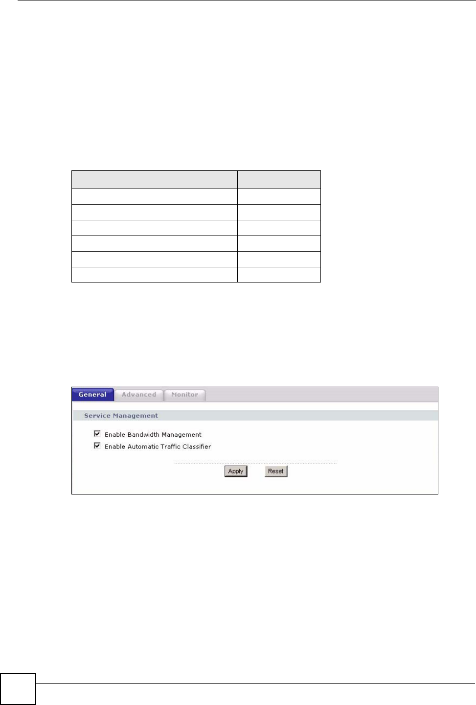
Chapter 15 Bandwidth Management
NBG318S User’s Guide
158
15.7 Default Bandwidth Management Classes and Priorities
If you enable bandwidth management but do not configure a rule for critical traffic like VoIP,
the voice traffic may then get delayed due to insufficient bandwidth. With the automatic traffic
classifier feature activated, the NBG318S automatically assigns a default bandwidth
management class and priority to traffic that does not match any of the user-defined rules. The
traffic is classified based on the traffic type. Real-time traffic always gets higher priority over
other traffic.
The following table shows you the priorities between the three default classes (AutoClass_H,
AutoClass_M and Default Class) and user-defined rules. 6 is the highest priority.
15.8 Bandwidth Management General Configuration
Click Management > Bandwidth MGMT to open the bandwidth management General
screen.
Figure 86 Management > Bandwidth MGMT > General
Table 59 Bandwidth Management Priority with Default Classes
CLASS TYPE PRIORITY
User-defined with high priority 6
AutoClass_H 5
User-defined with medium priority 4
AutoClass_M 3
User-defined with low priority 2
Default Class 1
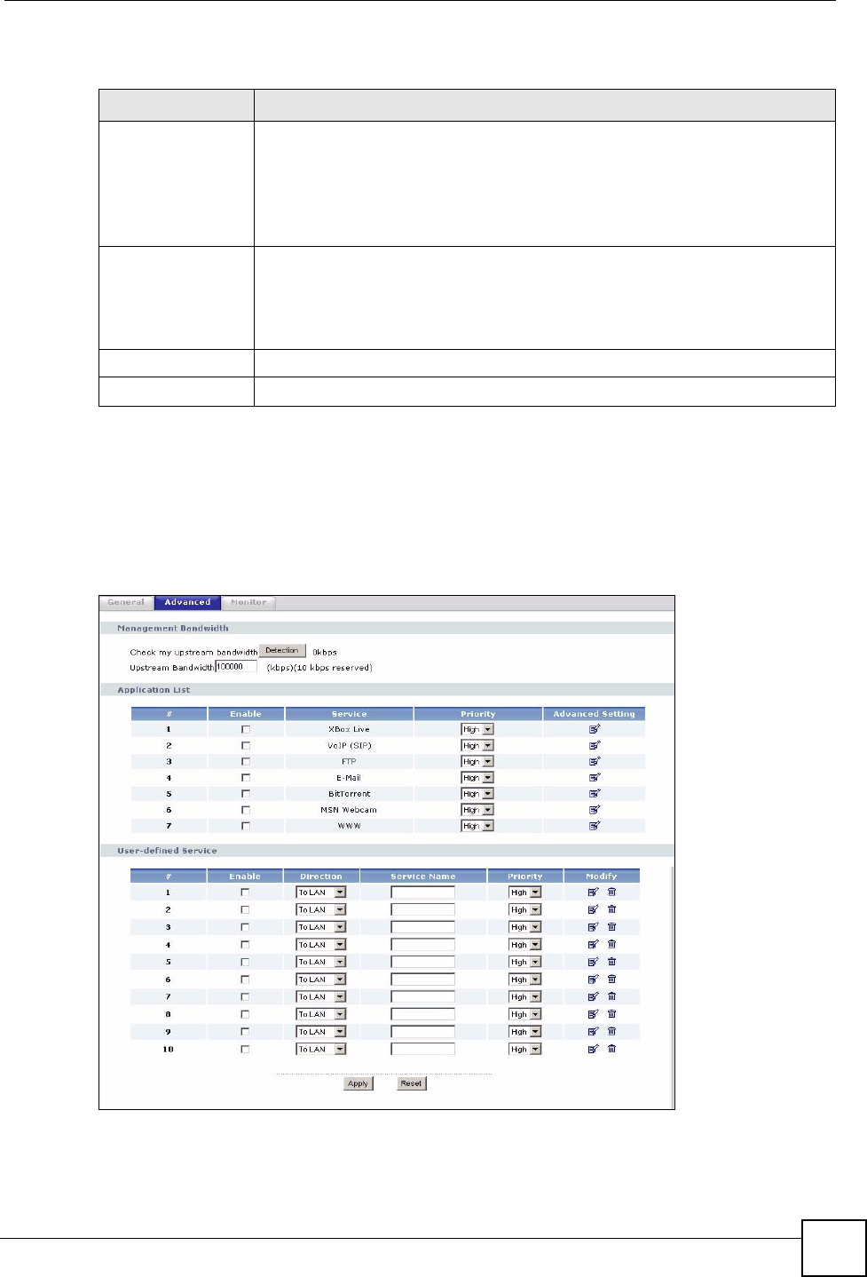
Chapter 15 Bandwidth Management
NBG318S User’s Guide 159
The following table describes the labels in this screen.
15.9 Bandwidth Management Advanced Configuration
Click Management > Bandwidth MGMT > Advanced to open the bandwidth management
Advanced screen.
Figure 87 Management > Bandwidth MGMT > Advanced
Table 60 Management > Bandwidth MGMT > General
LABEL DESCRIPTION
Enable Bandwidth
Management
Select this check box to have the NBG318S apply bandwidth management.
Enable bandwidth management to give traffic that matches a bandwidth rule
priority over traffic that does not match a bandwidth rule.
Enabling bandwidth management also allows you to control the maximum or
minimum amounts of bandwidth that can be used by traffic that matches a
bandwidth rule.
Enable Automatic
Traffic Classifier
This field is only applicable when you select the Enable Bandwidth
Management check box.
Select this check box to have the NBG318S base on the default bandwidth
classes to apply bandwidth management. Real-time packets, such as VoIP
traffic always get higher priority.
Apply Click Apply to save your customized settings.
Reset Click Reset to begin configuring this screen afresh.

Chapter 15 Bandwidth Management
NBG318S User’s Guide
160
The following table describes the labels in this screen.
15.9.1 Rule Configuration with the Pre-defined Service
To edit a bandwidth management rule for the pre-defined service in the NBG318S, click the
Edit icon in the Application List table of the Advanced screen. The following screen
displays.
Table 61 Management > Bandwidth MGMT > Advanced
LABEL DESCRIPTION
Check my
upstream
bandwidth
Click the Detection button to check the size of your upstream bandwidth.
Upstream
Bandwidth (kbps)
Enter the amount of bandwidth in kbps (2 to 100,000) that you want to allocate for
traffic. 20 kbps to 20,000 kbps is recommended.
The recommendation is to set this speed to be equal to or less than the speed of
the broadband device connected to the WAN port. For example, set the speed to
1000 Kbps (or less) if the broadband device connected to the WAN port has an
upstream speed of 1000 Kbps.
Application List Use this table to allocate specific amounts of bandwidth based on the pre-defined
service.
#This is the number of an individual bandwidth management rule.
Enable Select this check box to have the NBG318S apply this bandwidth management
rule.
Service This is the name of the service.
Priority Select a priority from the drop down list box. Choose High, Mid or Low.
Advanced Setting Click the Edit icon to open the Rule Configuration screen where you can modify
the rule.
User-defined
Service
Use this table to allocate specific amounts of bandwidth to specific applications
and/or subnets.
#This is the number of an individual bandwidth management rule.
Enable Select this check box to have the NBG318S apply this bandwidth management
rule.
Direction Select To LAN to apply bandwidth management to traffic that the NBG318S
forwards to the LAN.
Select To WAN to apply bandwidth management to traffic that the NBG318S
forwards to the WAN.
Select To WLAN to apply bandwidth management to traffic that the NBG318S
forwards to the WLAN.
Service Name Enter a descriptive name of up to 19 alphanumeric characters, including spaces.
Priority Select a priority from the drop down list box. Choose High, Mid or Low.
Modify Click the Edit icon to open the Rule Configuration screen. Modify an existing rule
or create a new rule in the Rule Configuration screen. See Section 15.9.2 on
page 161 for more information.
Click the Remove icon to delete a rule.
Apply Click Apply to save your customized settings.
Reset Click Reset to begin configuring this screen afresh.