ZyXEL Communications NBG318S Wireless Ethernet Adapter User Manual NBG 318 User s Guide
ZyXEL Communications Corporation Wireless Ethernet Adapter NBG 318 User s Guide
Contents
- 1. User Manual 1
- 2. Users Manual 2
- 3. Users Manual 3
- 4. Users Manual 4
Users Manual 3
Chapter 15 Bandwidth Management
NBG318S User’s Guide 161
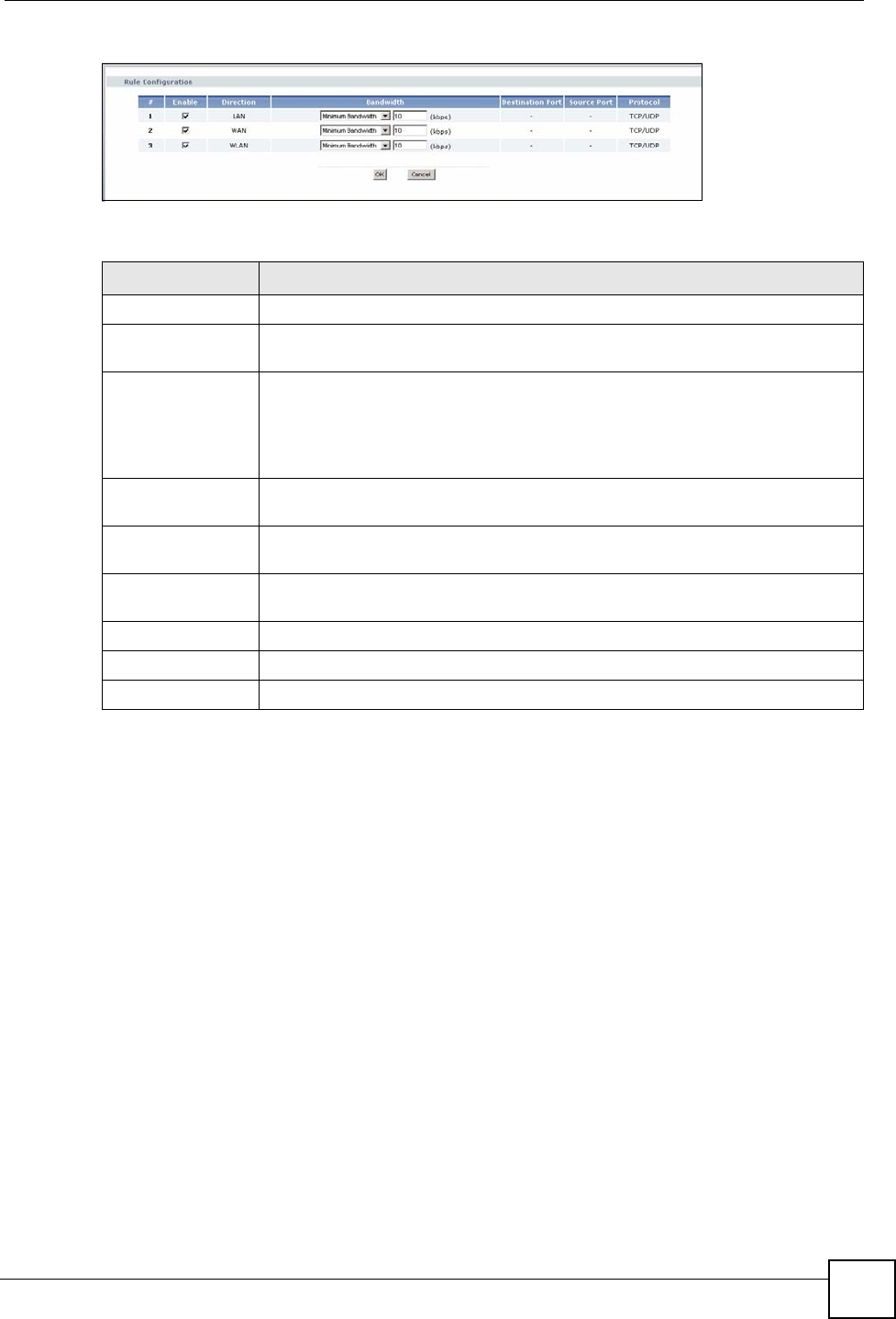
Figure 88 Management > Bandwidth MGMT > Advanced: Rule Configuration
The following table describes the labels in this screen.
15.9.2 Rule Configuration with the User-defined Service
In addition to the pre-defined services, if you want to edit a bandwidth management rule for
other applications and/or subnets, click the Edit icon in the User-defined Service table of the
Advanced screen. The following screen displays.
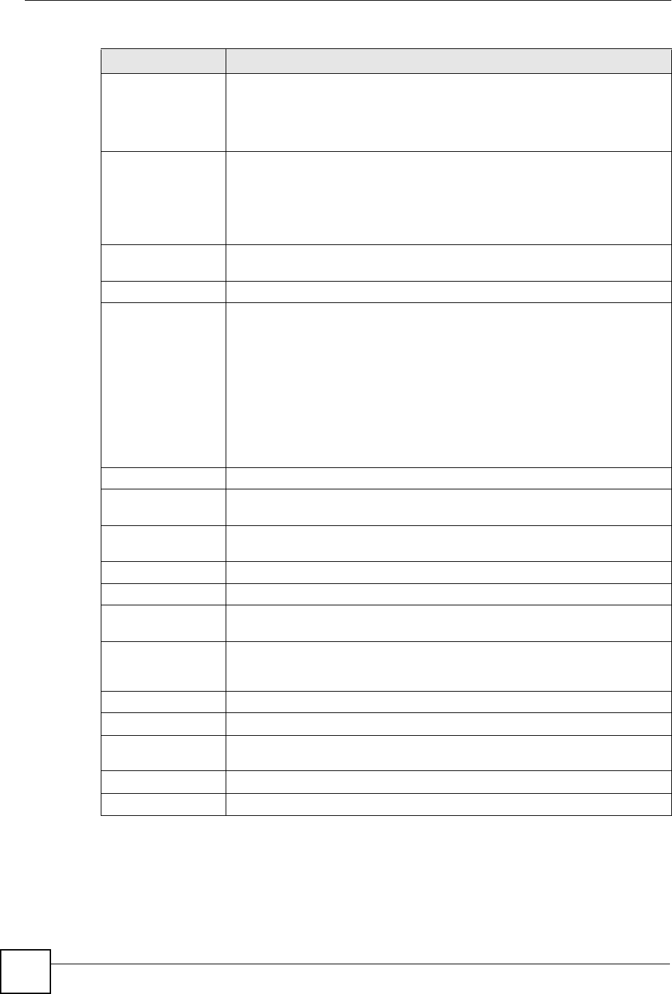
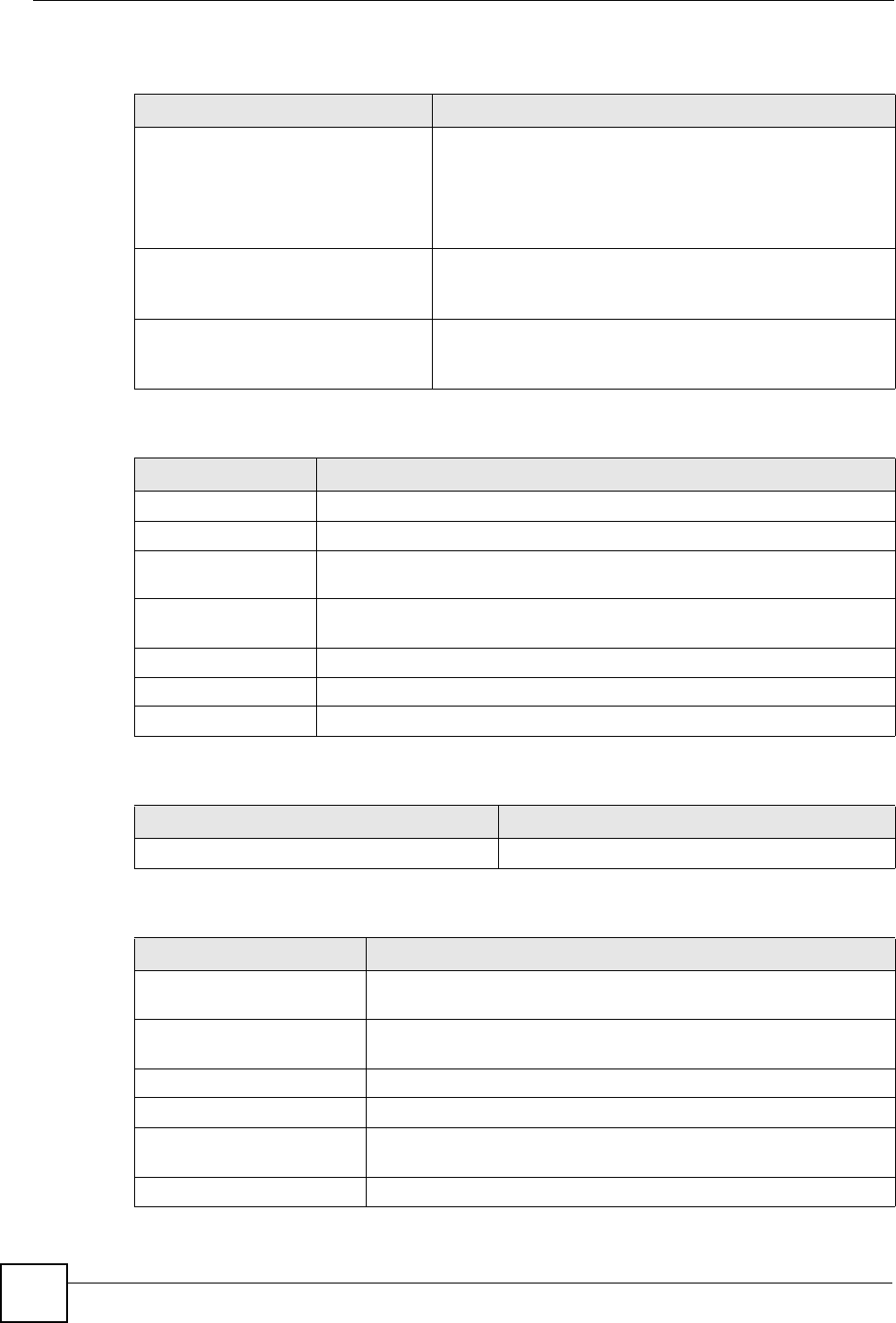
Table 62 Management > Bandwidth MGMT > Advanced: Application Rule Configuration
LABEL DESCRIPTION
#This is the number of an individual bandwidth management rule.
Enable Select an interface’s check box to enable bandwidth management on that
interface.
Direction These read-only labels represent the physical interfaces. Bandwidth
management applies to all traffic flowing out of the router through the interface,
regardless of the traffic’s source.
Traffic redirect or IP alias may cause LAN-to-LAN traffic to pass through the
NBG318S and be managed by bandwidth management.
Bandwidth Select Maximum Bandwidth or Minimum Bandwidth and specify the maximum
or minimum bandwidth allowed for the rule in kilobits per second.
Destination Port This is the port number of the destination. See Table 58 on page 156 for some
common services and port numbers.
Source Port This is the port number of the source. See Table 58 on page 156 for some
common services and port numbers.
Protocol This is the protocol (TCP or UDP) used for the service.
OK Click OK to save your customized settings.
Cancel Click Cancel to exit this screen without saving.
Chapter 15 Bandwidth Management
NBG318S User’s Guide
162
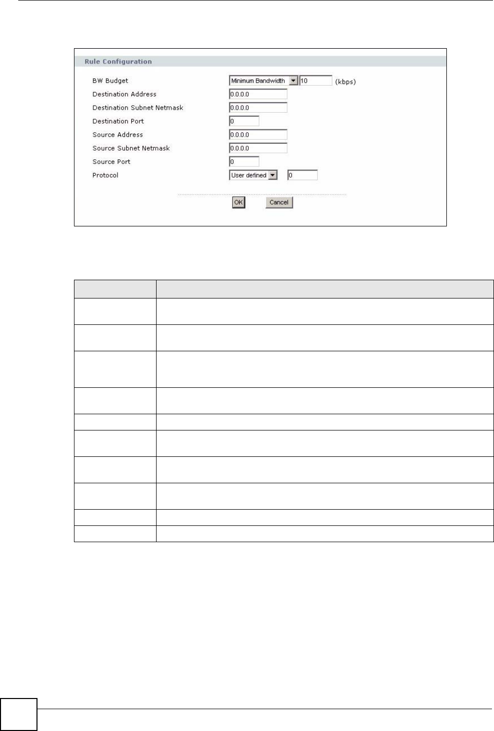
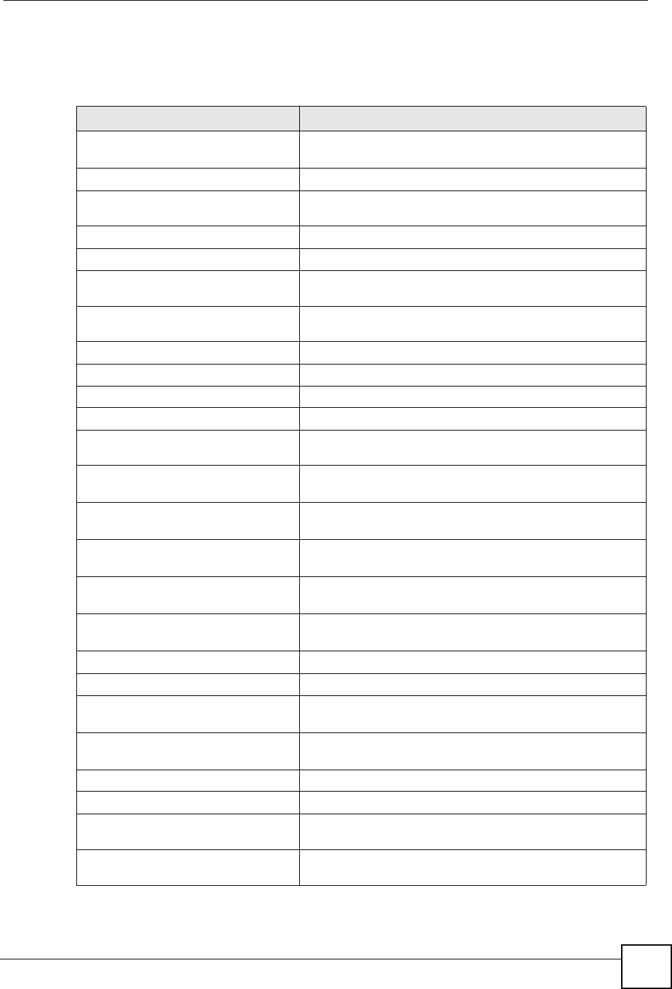
Figure 89 Management > Bandwidth MGMT > Advanced: User-defined Service Rule
Configuration
The following table describes the labels in this screen
Table 63 Management > Bandwidth MGMT > Advanced: User-defined Service Rule
Configuration
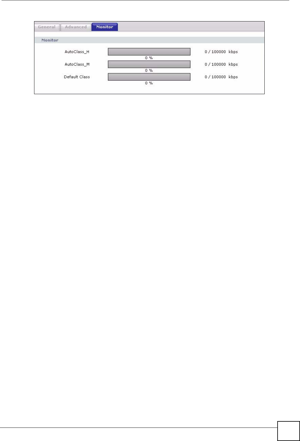
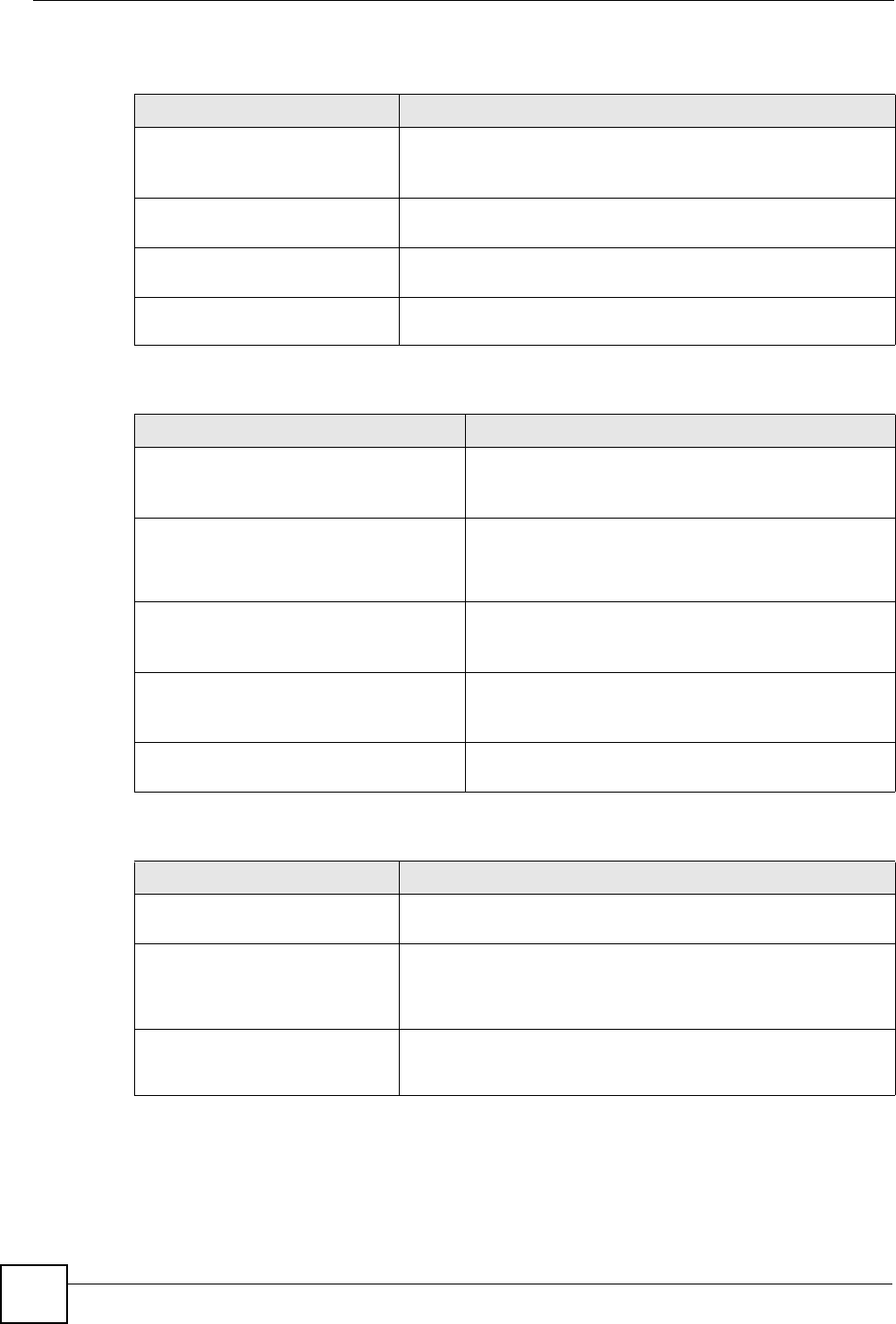
15.10 Bandwidth Management Monitor
Click Management > Bandwidth MGMT > Monitor to open the bandwidth management
Monitor screen. View the bandwidth usage of the WAN configured bandwidth rules. This is
also shown as bandwidth usage over the bandwidth budget for each rule. The gray section of
the bar represents the percentage of unused bandwidth and the blue color represents the
percentage of bandwidth in use.
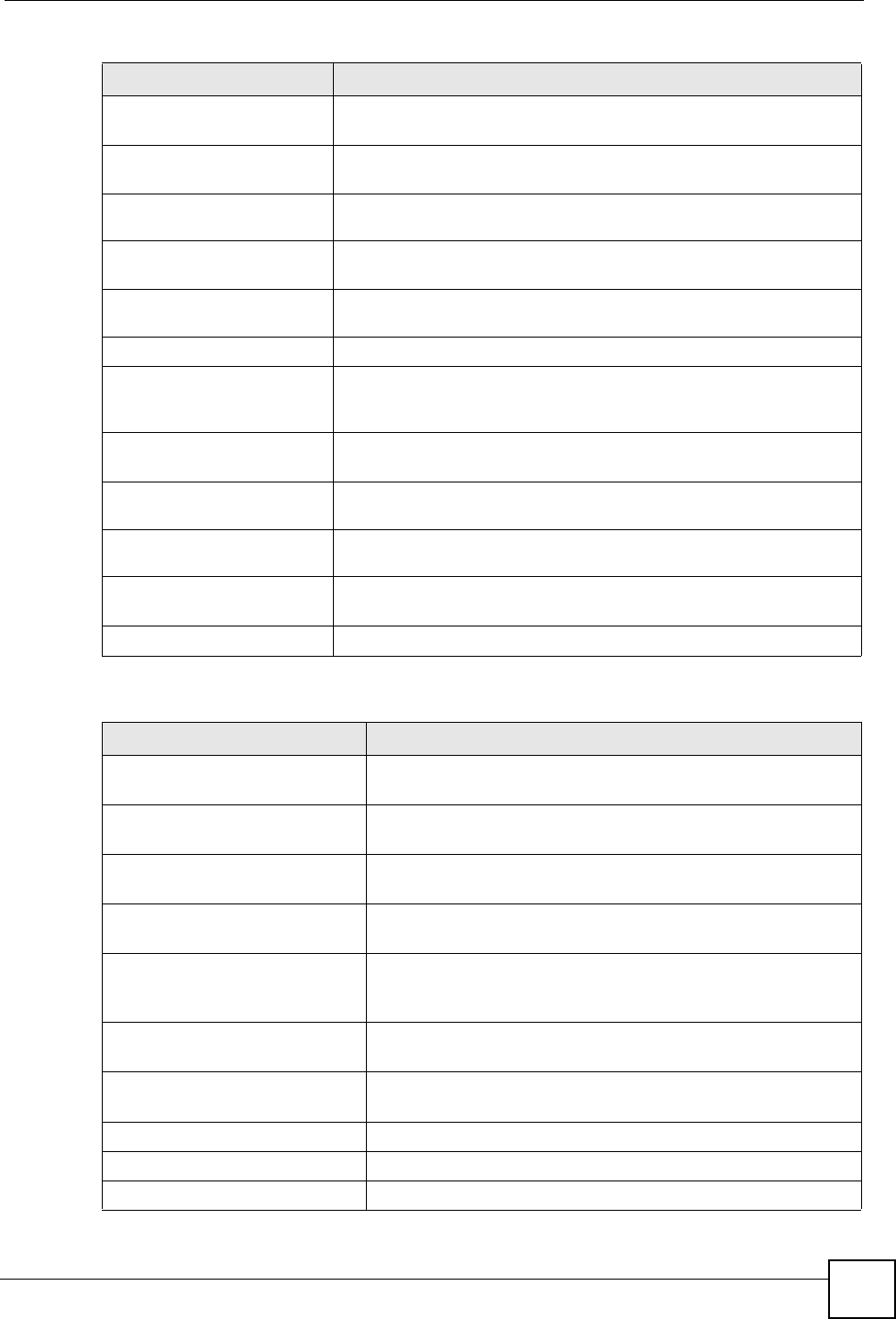
LABEL DESCRIPTION
BW Budget Select Maximum Bandwidth or Minimum Bandwidth and specify the maximum
or minimum bandwidth allowed for the rule in kilobits per second.
Destination
Address
Enter the destination IP address in dotted decimal notation.
Destination
Subnet Netmask
Enter the destination subnet mask. This field is N/A if you do not specify a
Destination Address. Refer to the appendices for more information on IP
subnetting.
Destination Port Enter the port number of the destination. See Table 58 on page 156 for some
common services and port numbers.
Source Address Enter the source IP address in dotted decimal notation.
Source Subnet
Netmask
Enter the destination subnet mask. This field is N/A if you do not specify a Source
Address. Refer to the appendices for more information on IP subnetting.
Source Port Enter the port number of the source. See Table 58 on page 156 for some common
services and port numbers.
Protocol Select the protocol (TCP or UDP) or select User defined and enter the protocol
(service type) number.
OK Click OK to save your customized settings.
Cancel Click Cancel to exit this screen without saving.
Chapter 15 Bandwidth Management
NBG318S User’s Guide 163
Figure 90 Management > Bandwidth MGMT > Monitor

Chapter 15 Bandwidth Management
NBG318S User’s Guide
164

NBG318S User’s Guide 165
CHAPTER 16
Remote Management
This chapter provides information on the Remote Management screens.
16.1 Remote Management Overview
Remote management allows you to determine which services/protocols can access which
NBG318S interface (if any) from which computers.
"When you configure remote management to allow management from the
WAN, you still need to configure a firewall rule to allow access. See the firewall
chapters for details on configuring firewall rules.
You may manage your NBG318S from a remote location via:
"When you choose WAN or LAN & WAN, you still need to configure a firewall
rule to allow access.
To disable remote management of a service, select Disable in the corresponding Server
Access field.
You may only have one remote management session running at a time. The NBG318S
automatically disconnects a remote management session of lower priority when another
remote management session of higher priority starts. The priorities for the different types of
remote management sessions are as follows.
1Telnet
2HTTP
16.1.1 Remote Management Limitations
Remote management over LAN or WAN will not work when:
• Internet (WAN only) • ALL (LAN and WAN)
• LAN only • Neither (Disable).
Chapter 16 Remote Management
NBG318S User’s Guide
166
1You have disabled that service in one of the remote management screens.
2The IP address in the Secured Client IP Address field does not match the client IP
address. If it does not match, the NBG318S will disconnect the session immediately.
3There is already another remote management session with an equal or higher priority
running. You may only have one remote management session running at one time.
4There is a firewall rule that blocks it.
16.1.2 Remote Management and NAT
When NAT is enabled:
• Use the NBG318S’s WAN IP address when configuring from the WAN.
• Use the NBG318S’s LAN IP address when configuring from the LAN.
16.1.3 System Timeout
There is a default system management idle timeout of five minutes (three hundred seconds).
The NBG318S automatically logs you out if the management session remains idle for longer
than this timeout period. The management session does not time out when a statistics screen is
polling. You can change the timeout period in the System screen
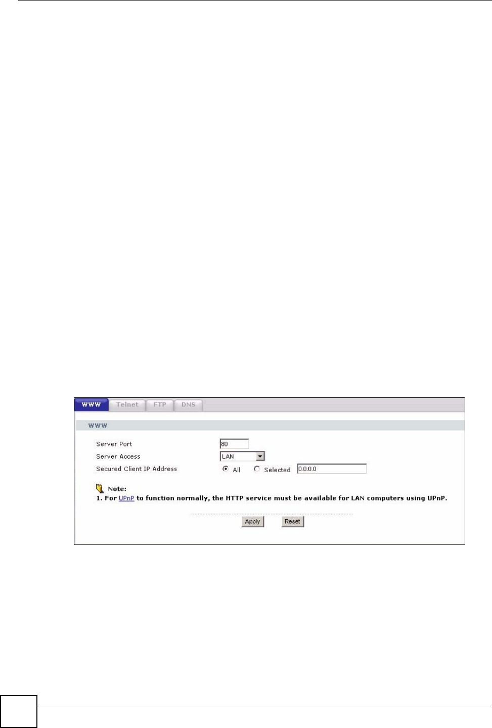
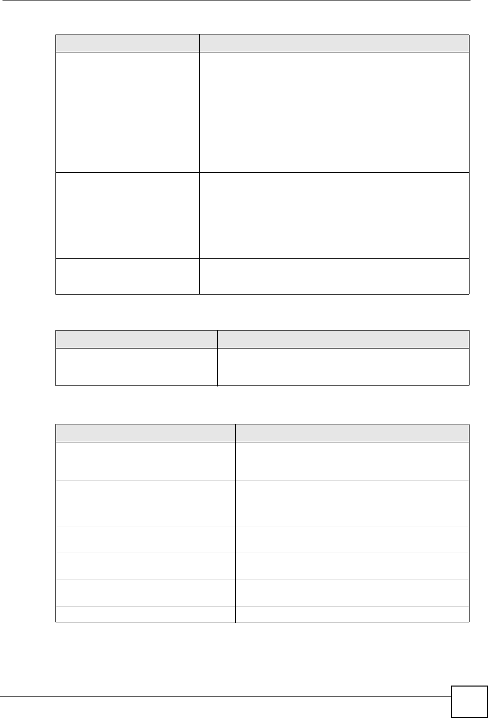
16.2 WWW Screen
To change your NBG318S’s World Wide Web settings, click Management > Remote
MGMT to display the WWW screen.
Figure 91 Management > Remote MGMT > WWW
The following table describes the labels in this screen
Table 64 Management > Remote MGMT > WWW
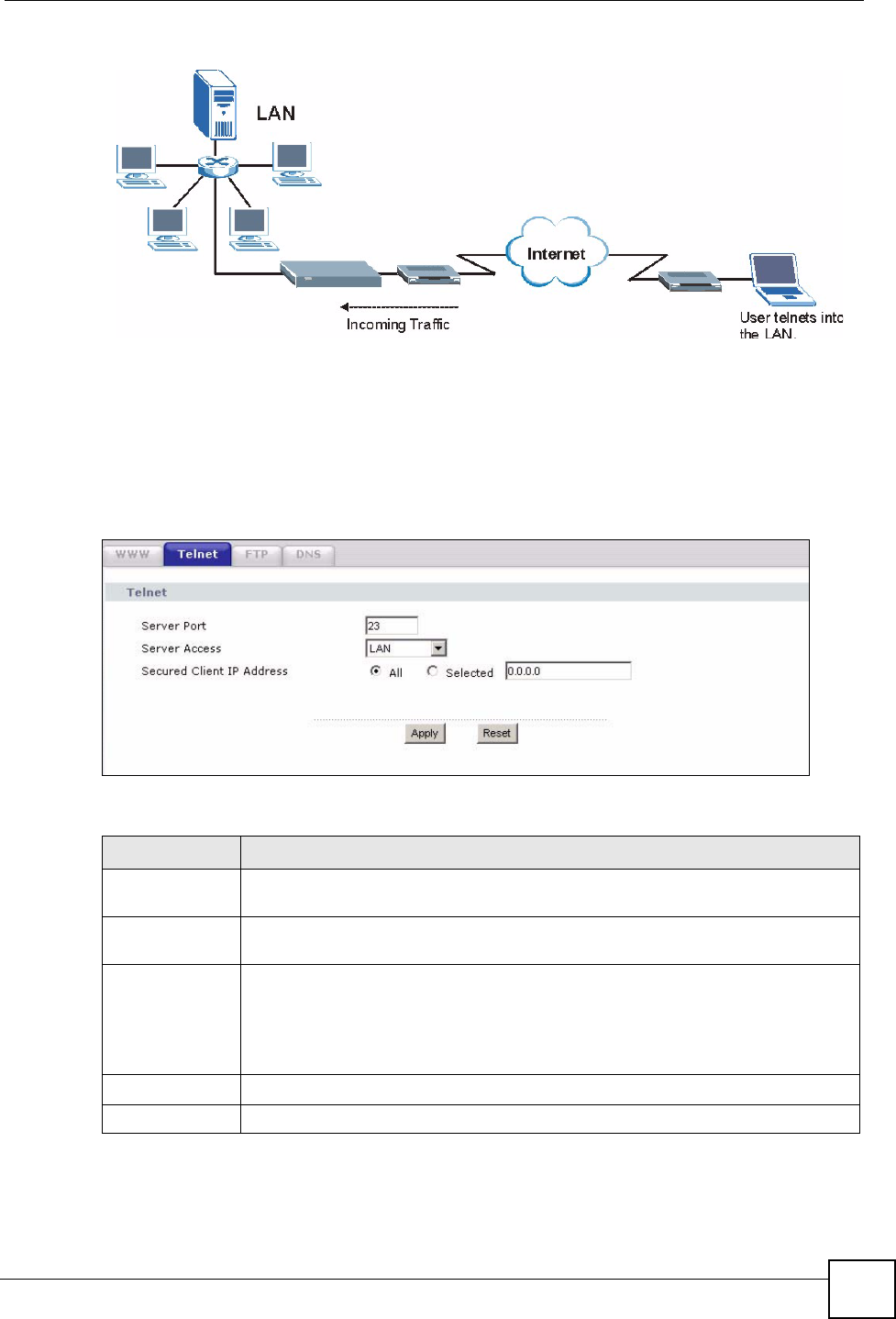
16.3 Telnet
You can configure your NBG318S for remote Telnet access as shown next. The administrator
uses Telnet from a computer on a remote network to access the NBG318S.
Chapter 16 Remote Management
NBG318S User’s Guide 167
Figure 92 Telnet Configuration on a TCP/IP Network
16.4 Telnet Screen
To change your NBG318S’s Telnet settings, click Management > Remote MGMT > Telnet.
The following screen displays.
Figure 93 Management > Remote MGMT > Telnet
The following table describes the labels in this screen.
Table 65 Management > Remote MGMT > Telnet
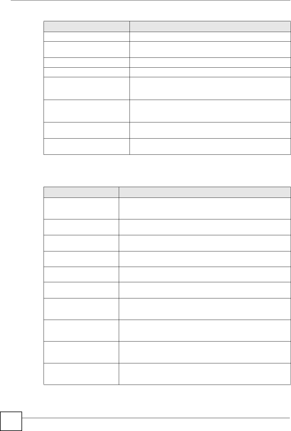
LABEL DESCRIPTION
Server Port You may change the server port number for a service if needed, however you must
use the same port number in order to use that service for remote management.
Server Access Select the interface(s) through which a computer may access the NBG318S using
this service.
Secured Client
IP Address
A secured client is a “trusted” computer that is allowed to communicate with the
NBG318S using this service.
Select All to allow any computer to access the NBG318S using this service.
Choose Selected to just allow the computer with the IP address that you specify to
access the NBG318S using this service.
Apply Click Apply to save your customized settings and exit this screen.
Reset Click Reset to begin configuring this screen afresh.
Chapter 16 Remote Management
NBG318S User’s Guide
168
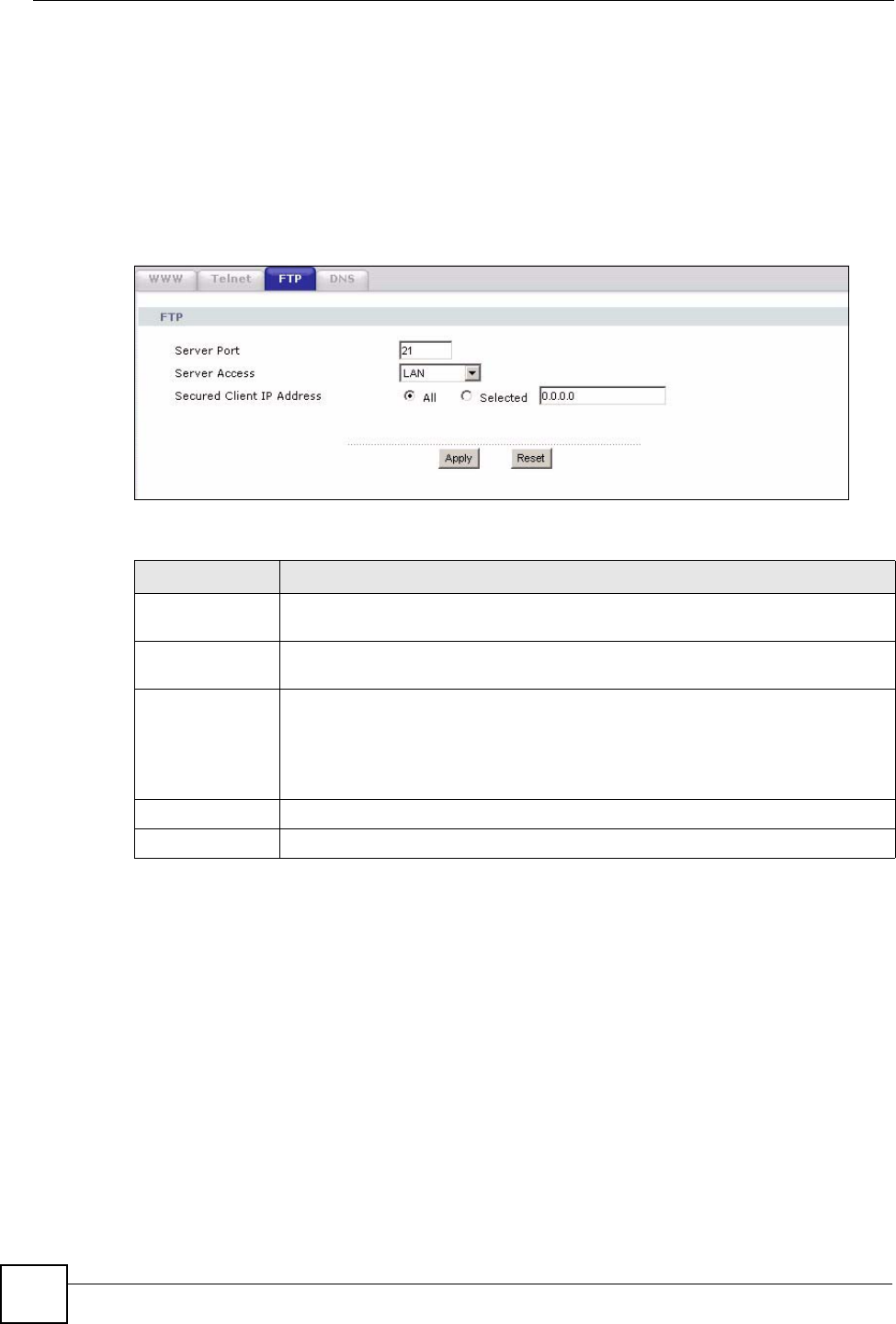
16.5 FTP Screen
You can upload and download the NBG318S’s firmware and configuration files using FTP,
please see the chapter on firmware and configuration file maintenance for details. To use this
feature, your computer must have an FTP client.
To change your NBG318S’s FTP settings, click Management > Remote MGMT > FTP. The
screen appears as shown.
Figure 94 Management > Remote MGMT > FTP
The following table describes the labels in this screen.
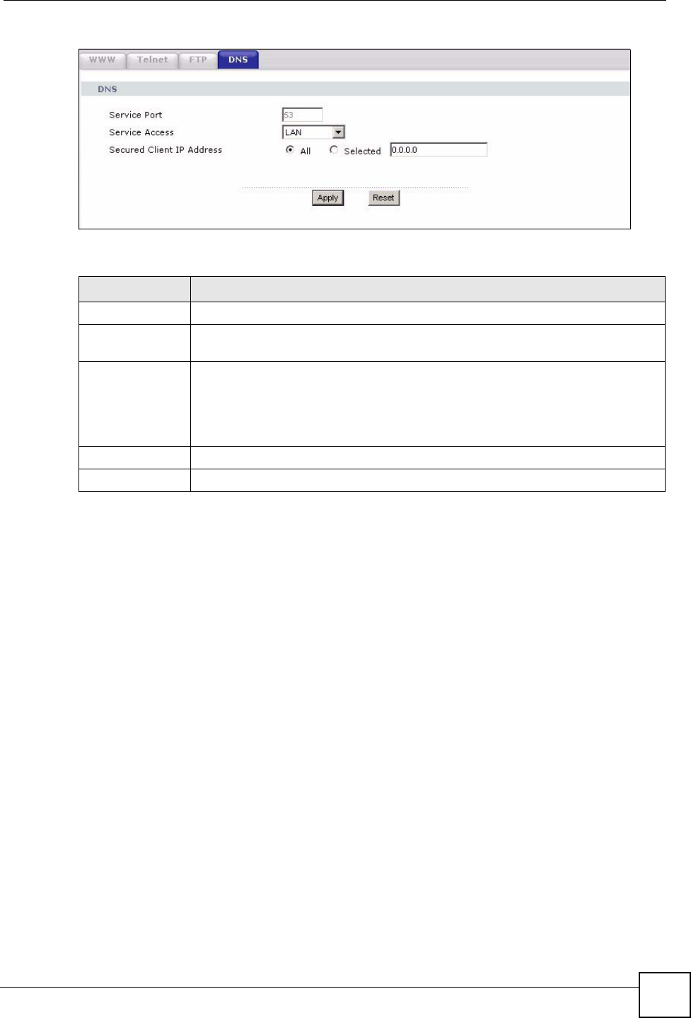
16.6 DNS Screen
Use DNS (Domain Name System) to map a domain name to its corresponding IP address and
vice versa. Refer to the chapter on Wizard Setup for background information.
To change your NBG318S’s DNS settings, click Management > Remote MGMT > DNS.
The screen appears as shown.
Table 66 Management > Remote MGMT > FTP
LABEL DESCRIPTION
Server Port You may change the server port number for a service if needed, however you must
use the same port number in order to use that service for remote management.
Server Access Select the interface(s) through which a computer may access the NBG318S using
this service.
Secured Client IP
Address
A secured client is a “trusted” computer that is allowed to communicate with the
NBG318S using this service.
Select All to allow any computer to access the NBG318S using this service.
Choose Selected to just allow the computer with the IP address that you specify to
access the NBG318S using this service.
Apply Click Apply to save your customized settings and exit this screen.
Reset Click Reset to begin configuring this screen afresh.
Chapter 16 Remote Management
NBG318S User’s Guide 169
Figure 95 Management > Remote MGMT > DNS
The following table describes the labels in this screen.
Table 67 Management > Remote MGMT > DNS
LABEL DESCRIPTION
Server Port The DNS service port number is 53 and cannot be changed here.
Server Access Select the interface(s) through which a computer may send DNS queries to the
NBG318S.
Secured Client IP
Address
A secured client is a “trusted” computer that is allowed to send DNS queries to the
NBG318S.
Select All to allow any computer to send DNS queries to the NBG318S.
Choose Selected to just allow the computer with the IP address that you specify to
send DNS queries to the NBG318S.
Apply Click Apply to save your customized settings and exit this screen.
Reset Click Reset to begin configuring this screen afresh.

Chapter 16 Remote Management
NBG318S User’s Guide
170

NBG318S User’s Guide 171
CHAPTER 17
Universal Plug-and-Play (UPnP)
This chapter introduces the UPnP feature in the web configurator.
17.1 Introducing Universal Plug and Play
Universal Plug and Play (UPnP) is a distributed, open networking standard that uses TCP/IP
for simple peer-to-peer network connectivity between devices. A UPnP device can
dynamically join a network, obtain an IP address, convey its capabilities and learn about other
devices on the network. In turn, a device can leave a network smoothly and automatically
when it is no longer in use.
See Section 17.3 on page 172 for configuration instructions.
17.1.1 How do I know if I'm using UPnP?
UPnP hardware is identified as an icon in the Network Connections folder (Windows XP).
Each UPnP compatible device installed on your network will appear as a separate icon.
Selecting the icon of a UPnP device will allow you to access the information and properties of
that device.
17.1.2 NAT Traversal
UPnP NAT traversal automates the process of allowing an application to operate through
NAT. UPnP network devices can automatically configure network addressing, announce their
presence in the network to other UPnP devices and enable exchange of simple product and
service descriptions. NAT traversal allows the following:
• Dynamic port mapping
• Learning public IP addresses
• Assigning lease times to mappings
Windows Messenger is an example of an application that supports NAT traversal and UPnP.
See the NAT chapter for more information on NAT.
17.1.3 Cautions with UPnP
The automated nature of NAT traversal applications in establishing their own services and
opening firewall ports may present network security issues. Network information and
configuration may also be obtained and modified by users in some network environments.
Chapter 17 Universal Plug-and-Play (UPnP)
NBG318S User’s Guide
172
When a UPnP device joins a network, it announces its presence with a multicast message. For
security reasons, the NBG318S allows multicast messages on the LAN only.
All UPnP-enabled devices may communicate freely with each other without additional
configuration. Disable UPnP if this is not your intention.
17.2 UPnP and ZyXEL
ZyXEL has achieved UPnP certification from the Universal Plug and Play Forum UPnP™
Implementers Corp. (UIC). ZyXEL's UPnP implementation supports Internet Gateway Device
(IGD) 1.0.
See the following sections for examples of installing and using UPnP.
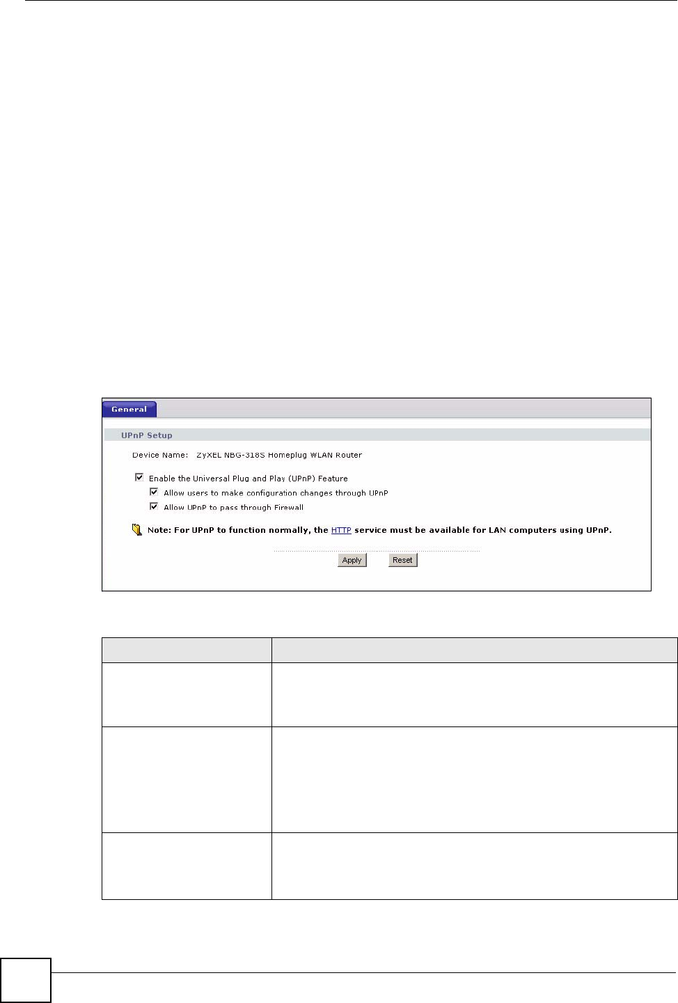
17.3 UPnP Screen
Click the Management > UPnP to display the UPnP screen.
Figure 96 Management > UPnP > General
The following table describes the labels in this screen.
Table 68 Management > UPnP > General
LABEL DESCRIPTION
Enable the Universal Plug
and Play (UPnP) Feature
Select this check box to activate UPnP. Be aware that anyone could
use a UPnP application to open the web configurator's login screen
without entering the NBG318S's IP address (although you must still
enter the password to access the web configurator).
Allow users to make
configuration changes
through UPnP
Select this check box to allow UPnP-enabled applications to
automatically configure the NBG318S so that they can communicate
through the NBG318S, for example by using NAT traversal, UPnP
applications automatically reserve a NAT forwarding port in order to
communicate with another UPnP enabled device; this eliminates the
need to manually configure port forwarding for the UPnP enabled
application.
Allow UPnP to pass through
Firewall
Select this check box to allow traffic from UPnP-enabled applications to
bypass the firewall.
Clear this check box to have the firewall block all UPnP application
packets (for example, MSN packets).
Chapter 17 Universal Plug-and-Play (UPnP)
NBG318S User’s Guide 173
17.4 Installing UPnP in Windows Example
This section shows how to install UPnP in Windows Me and Windows XP.
17.4.0.1 Installing UPnP in Windows Me
Follow the steps below to install the UPnP in Windows Me.
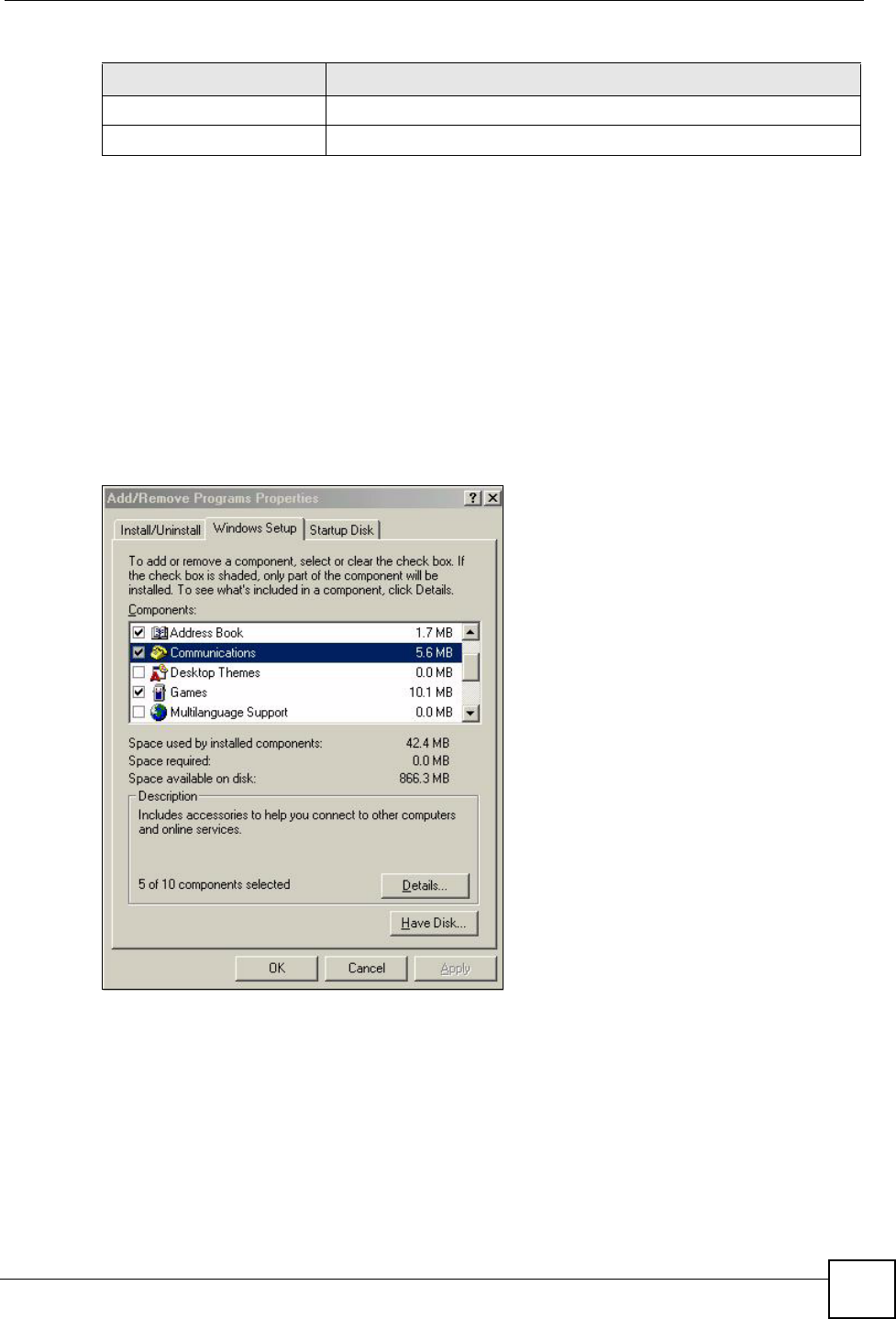
1Click Start and Control Panel. Double-click Add/Remove Programs.
2Click on the Windows Setup tab and select Communication in the Components
selection box. Click Details.
Figure 97 Add/Remove Programs: Windows Setup: Communication
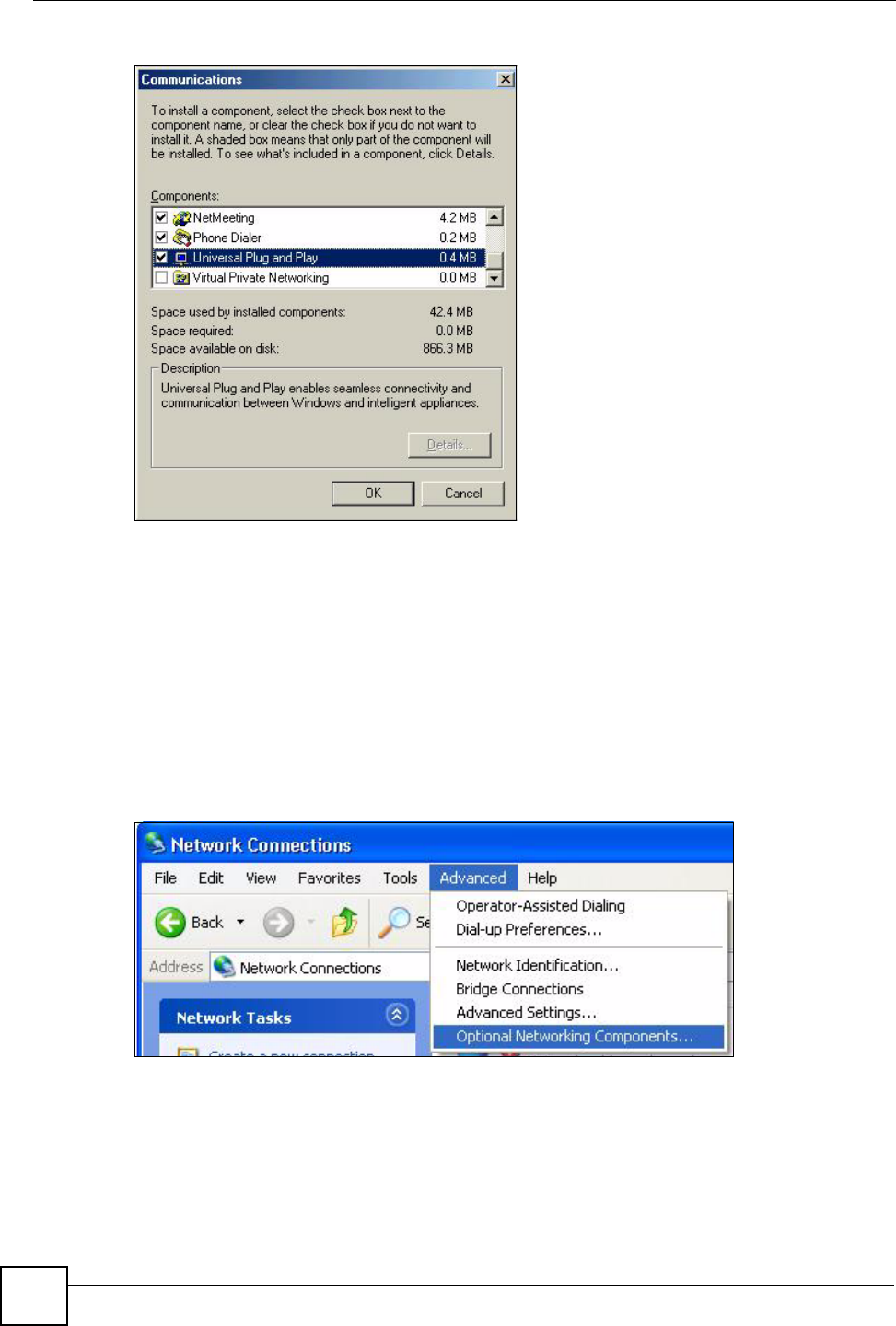
3In the Communications window, select the Universal Plug and Play check box in the
Components selection box.
Apply Click Apply to save the setting to the NBG318S.
Cancel Click Cancel to return to the previously saved settings.
Table 68 Management > UPnP > General
LABEL DESCRIPTION
Chapter 17 Universal Plug-and-Play (UPnP)
NBG318S User’s Guide
174
Figure 98 Add/Remove Programs: Windows Setup: Communication: Components
4Click OK to go back to the Add/Remove Programs Properties window and click
Next.
5Restart the computer when prompted.
Installing UPnP in Windows XP
Follow the steps below to install the UPnP in Windows XP.
1Click Start and Control Panel.
2Double-click Network Connections.
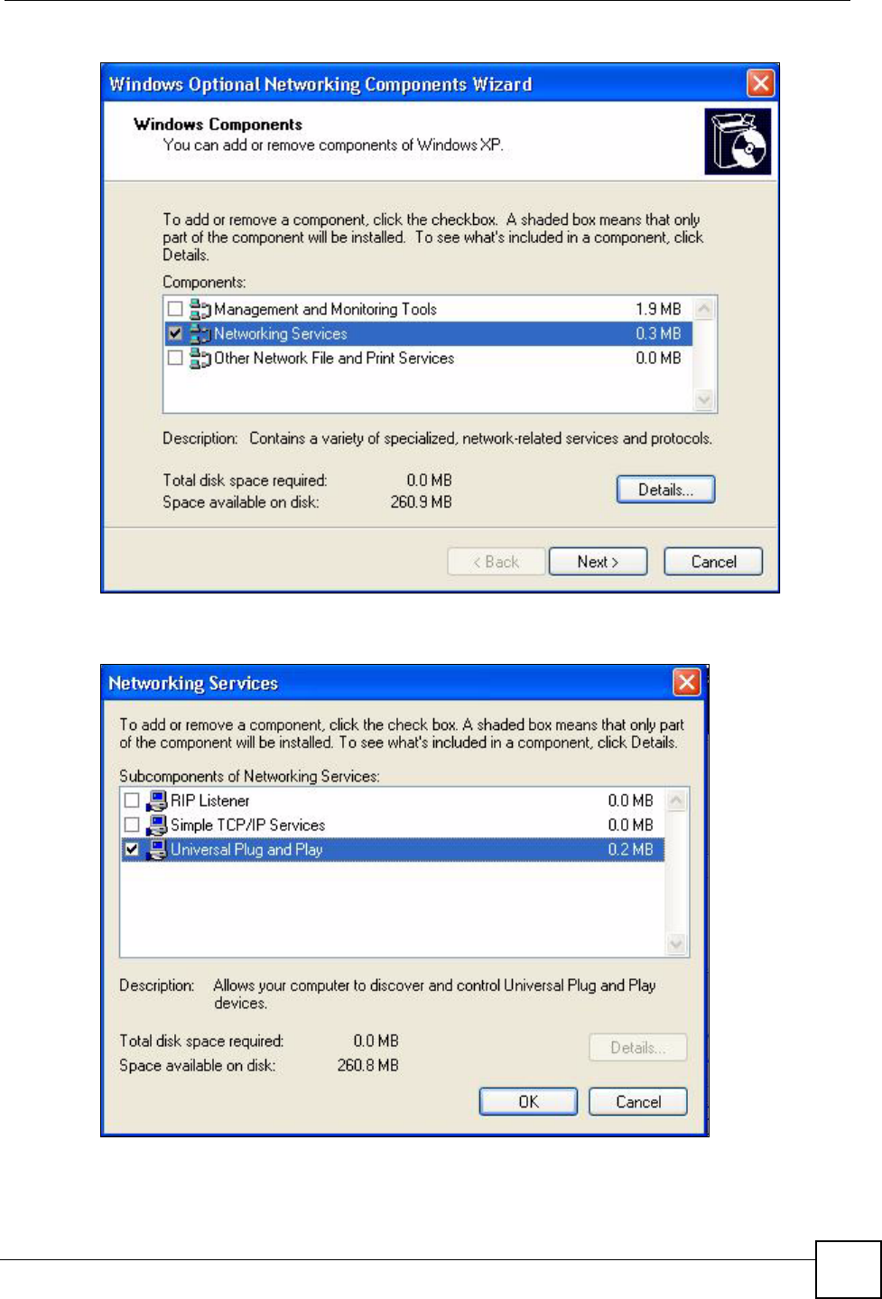
3In the Network Connections window, click Advanced in the main menu and select
Optional Networking Components ….
Figure 99 Network Connections
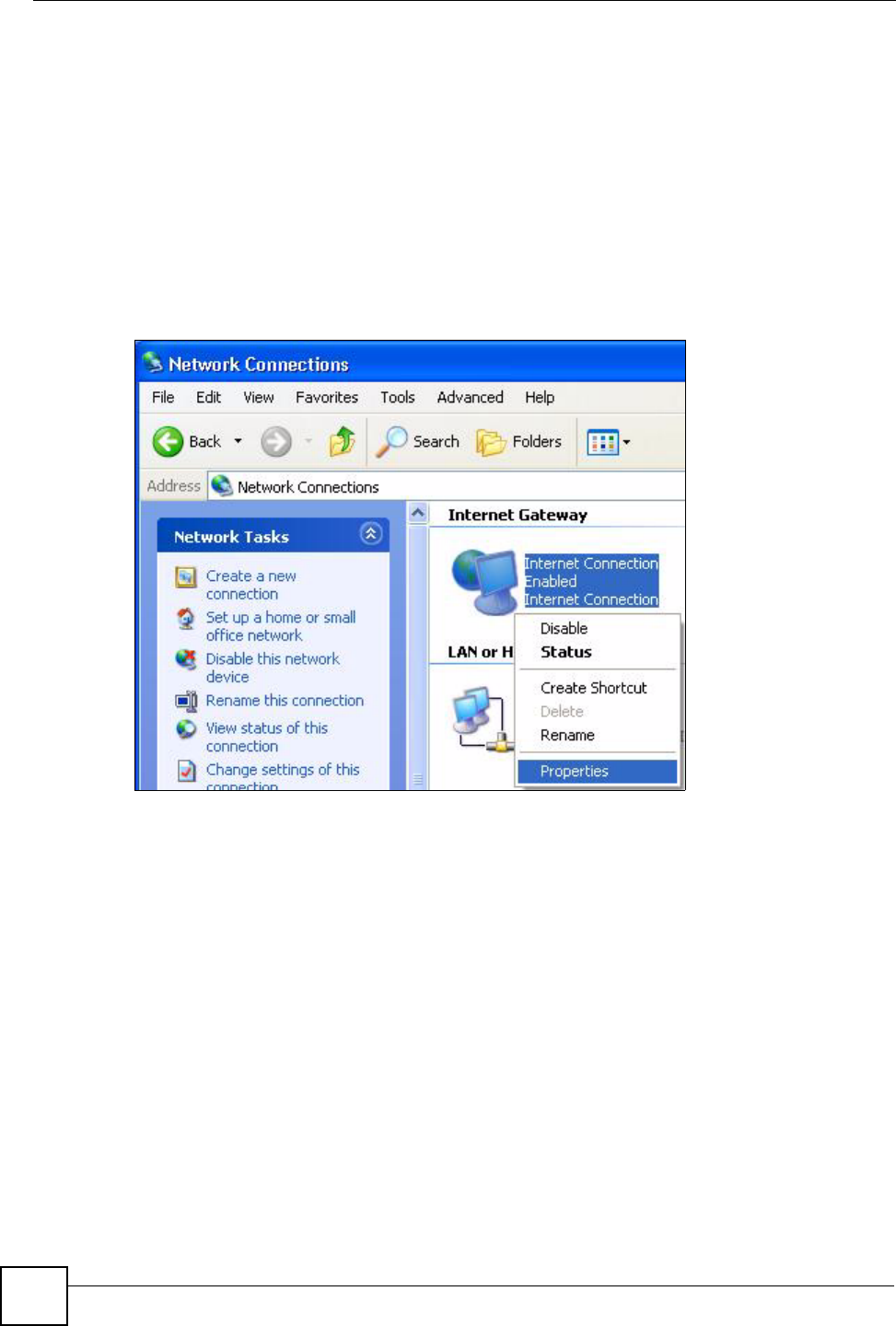
4The Windows Optional Networking Components Wizard window displays. Select
Networking Service in the Components selection box and click Details.
Chapter 17 Universal Plug-and-Play (UPnP)
NBG318S User’s Guide 175
Figure 100 Windows Optional Networking Components Wizard
5In the Networking Services window, select the Universal Plug and Play check box.
Figure 101 Networking Services
6Click OK to go back to the Windows Optional Networking Component Wizard
window and click Next.
Chapter 17 Universal Plug-and-Play (UPnP)
NBG318S User’s Guide
176
17.4.0.2 Using UPnP in Windows XP Example
This section shows you how to use the UPnP feature in Windows XP. You must already have
UPnP installed in Windows XP and UPnP activated on the NBG318S.
Make sure the computer is connected to a LAN port of the NBG318S. Turn on your computer
and the NBG318S.
Auto-discover Your UPnP-enabled Network Device
1Click Start and Control Panel. Double-click Network Connections. An icon displays
under Internet Gateway.
2Right-click the icon and select Properties.
Figure 102 Network Connections
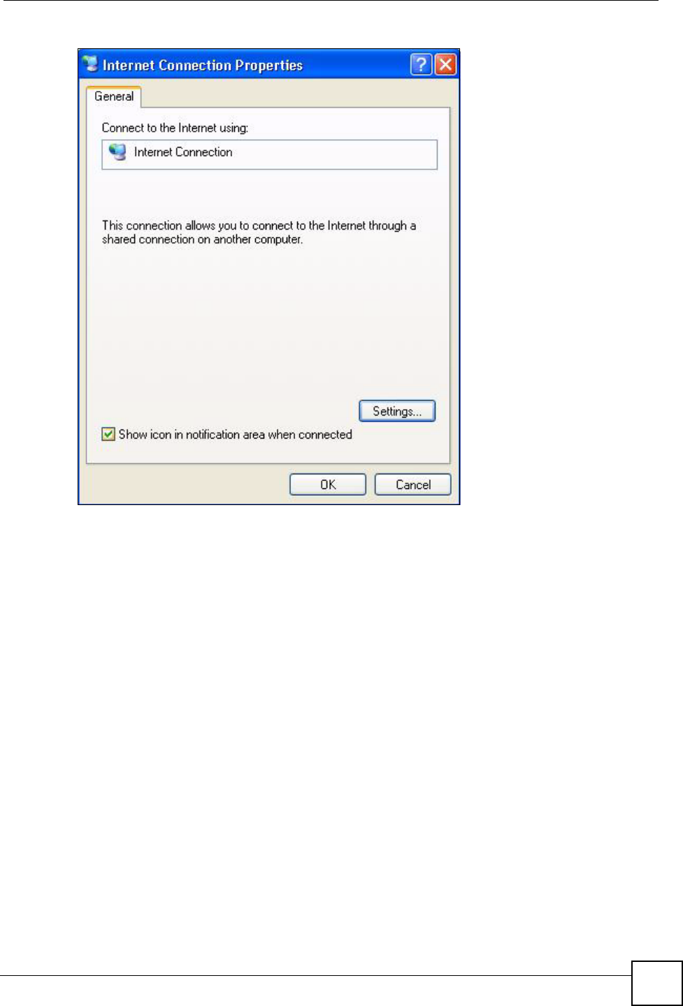
3In the Internet Connection Properties window, click Settings to see the port mappings
there were automatically created.
Chapter 17 Universal Plug-and-Play (UPnP)
NBG318S User’s Guide 177
Figure 103 Internet Connection Properties
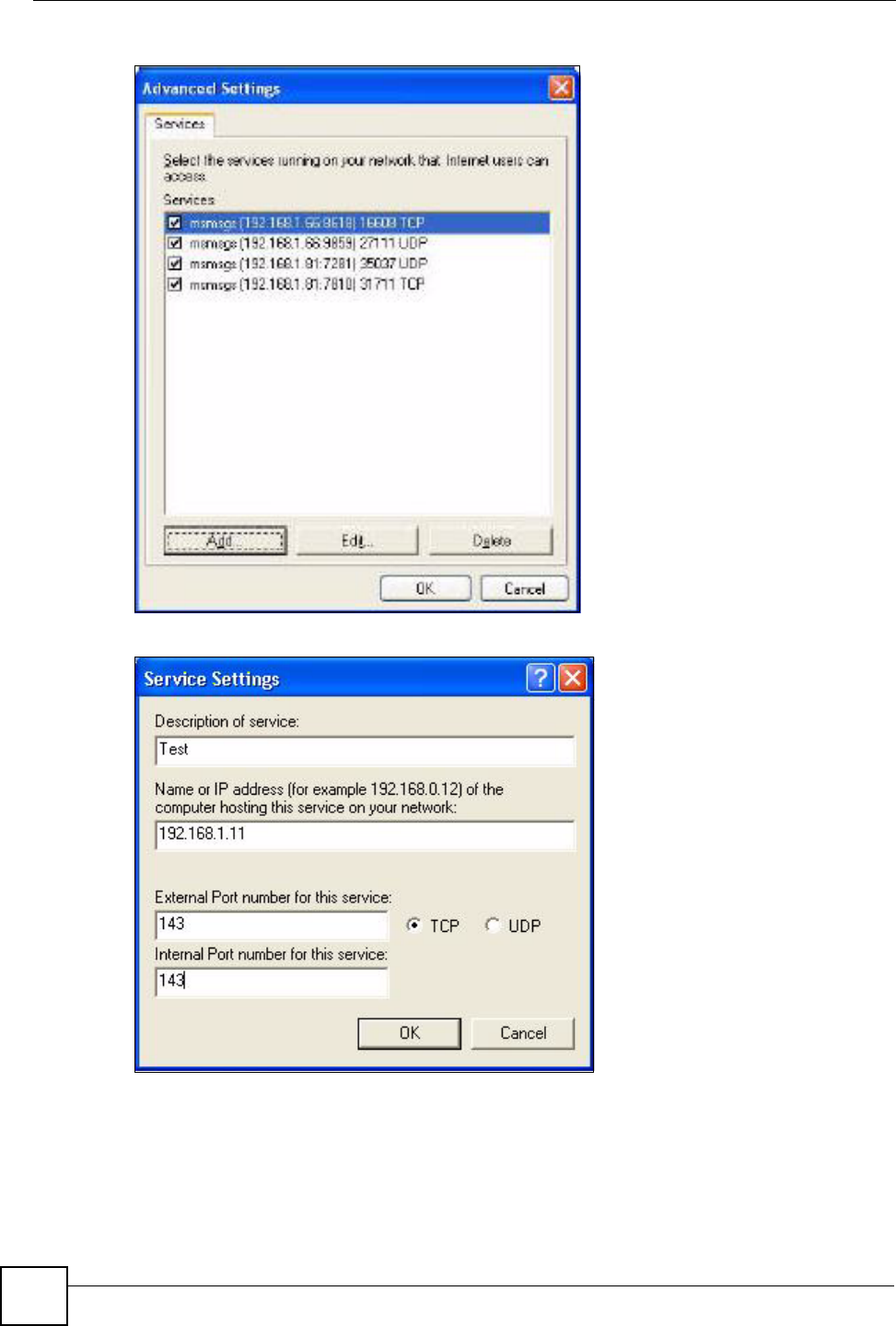
4You may edit or delete the port mappings or click Add to manually add port mappings.
Chapter 17 Universal Plug-and-Play (UPnP)
NBG318S User’s Guide
178
Figure 104 Internet Connection Properties: Advanced Settings
Figure 105 Internet Connection Properties: Advanced Settings: Add
5When the UPnP-enabled device is disconnected from your computer, all port mappings
will be deleted automatically.
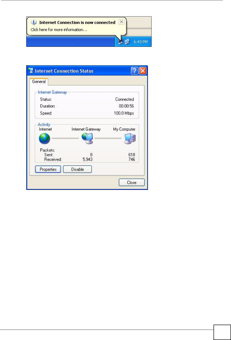
6Select Show icon in notification area when connected option and click OK. An icon
displays in the system tray.
Chapter 17 Universal Plug-and-Play (UPnP)
NBG318S User’s Guide 179
Figure 106 System Tray Icon
7Double-click on the icon to display your current Internet connection status.
Figure 107 Internet Connection Status
Web Configurator Easy Access
With UPnP, you can access the web-based configurator on the NBG318S without finding out
the IP address of the NBG318S first. This comes helpful if you do not know the IP address of
the NBG318S.
Follow the steps below to access the web configurator.
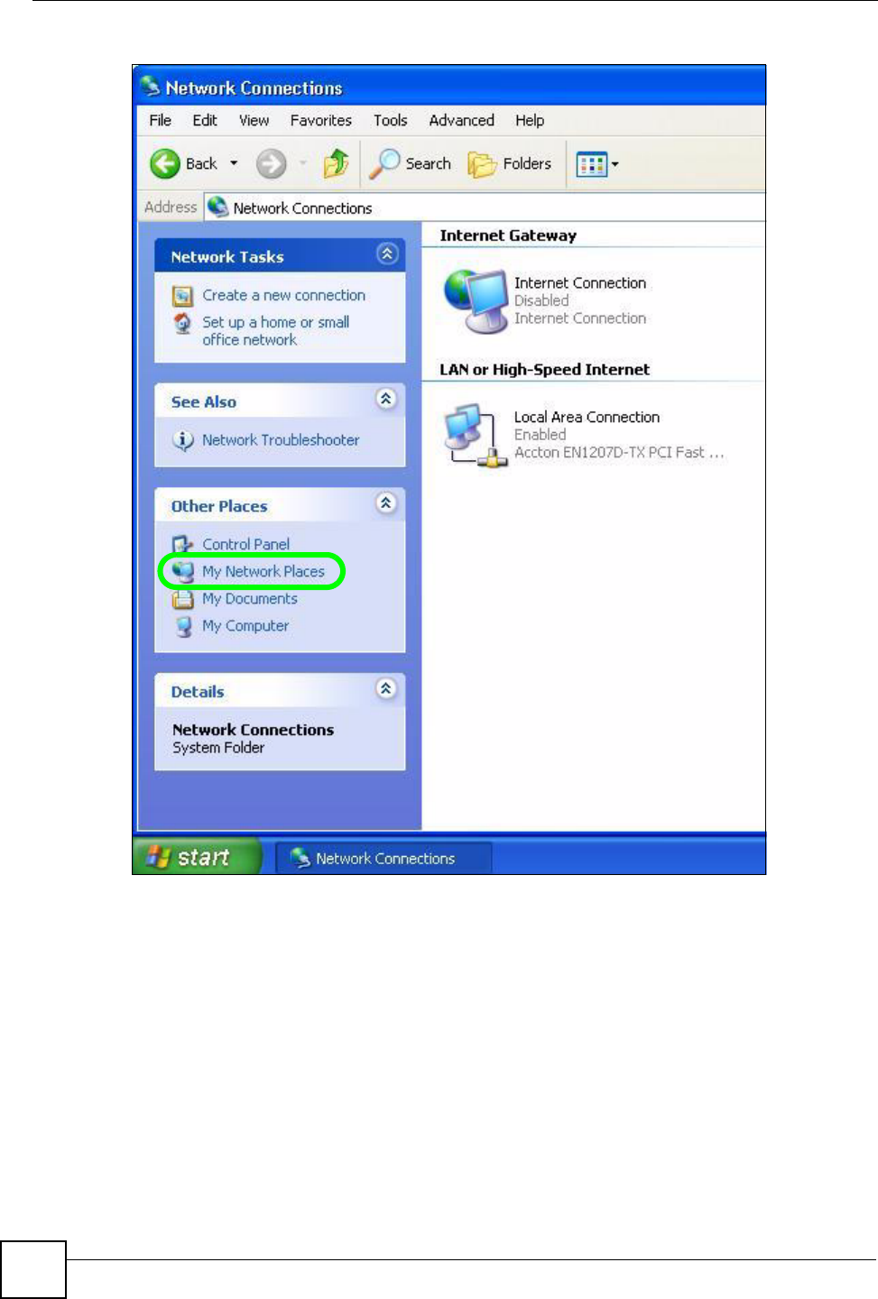
1Click Start and then Control Panel.
2Double-click Network Connections.
3Select My Network Places under Other Places.
Chapter 17 Universal Plug-and-Play (UPnP)
NBG318S User’s Guide
180
Figure 108 Network Connections
4An icon with the description for each UPnP-enabled device displays under Local
Network.
5Right-click on the icon for your NBG318S and select Invoke. The web configurator
login screen displays.
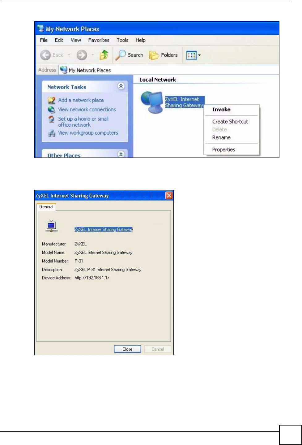
Chapter 17 Universal Plug-and-Play (UPnP)
NBG318S User’s Guide 181
Figure 109 Network Connections: My Network Places
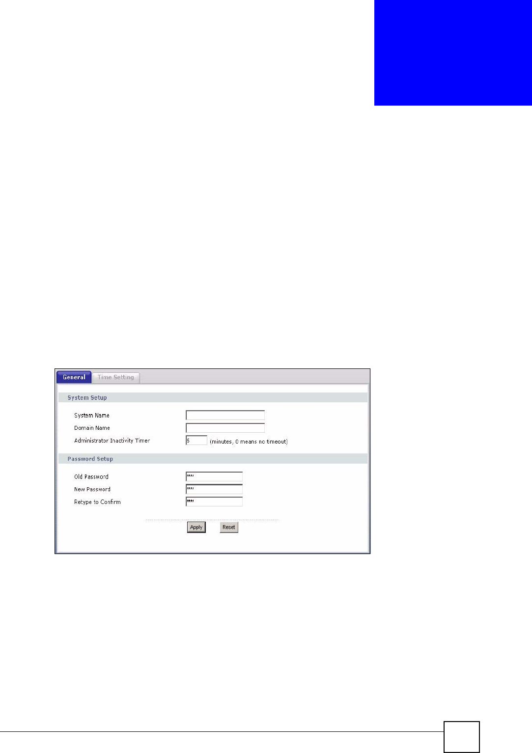
6Right-click on the icon for your NBG318S and select Properties. A properties window
displays with basic information about the NBG318S.
Figure 110 Network Connections: My Network Places: Properties: Example

Chapter 17 Universal Plug-and-Play (UPnP)
NBG318S User’s Guide
182

183
PART V
Maintenance and
Troubleshooting
System (185)
Logs (189)
Tools (203)
Configuration Mode (209)
Sys Op Mode (211)
Troubleshooting (213)

184
NBG318S User’s Guide 185
CHAPTER 18
System
This chapter provides information on the System screens.
18.1 System Overview
See the chapter about wizard setup for more information on the next few screens.
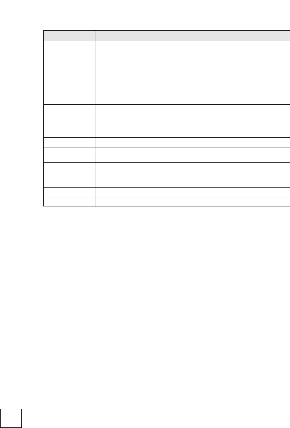
18.2 System General Screen
Click Maintenance > System. The following screen displays.
Figure 111 Maintenance > System > General
Chapter 18 System
NBG318S User’s Guide
186
The following table describes the labels in this screen.
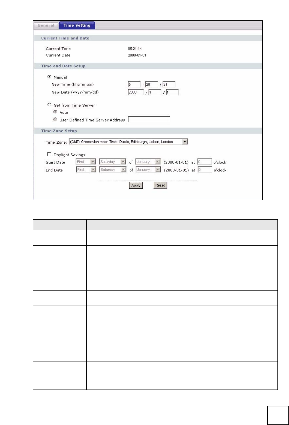
18.3 Time Setting Screen
To change your NBG318S’s time and date, click Maintenance > System > Time Setting. The
screen appears as shown. Use this screen to configure the NBG318S’s time based on your
local time zone.
Table 69 Maintenance > System > General
LABEL DESCRIPTION
System Name System Name is a unique name to identify the NBG318S in an Ethernet network.
It is recommended you enter your computer’s “Computer name” in this field (see
the chapter about wizard setup for how to find your computer’s name).
This name can be up to 30 alphanumeric characters long. Spaces are not
allowed, but dashes “-” and underscores "_" are accepted.
Domain Name Enter the domain name (if you know it) here. If you leave this field blank, the ISP
may assign a domain name via DHCP.
The domain name entered by you is given priority over the ISP assigned domain
name.
Administrator
Inactivity Timer
Type how many minutes a management session can be left idle before the
session times out. The default is 5 minutes. After it times out you have to log in
with your password again. Very long idle timeouts may have security risks. A
value of "0" means a management session never times out, no matter how long it
has been left idle (not recommended).
Password Setup Change your NBG318S’s password (recommended) using the fields as shown.
Old Password Type the default password or the existing password you use to access the
system in this field.
New Password Type your new system password (up to 30 characters). Note that as you type a
password, the screen displays an asterisk (*) for each character you type.
Retype to Confirm Type the new password again in this field.
Apply Click Apply to save your changes back to the NBG318S.
Reset Click Reset to begin configuring this screen afresh.
Chapter 18 System
NBG318S User’s Guide 187
Figure 112 Maintenance > System > Time Setting
The following table describes the labels in this screen.
Table 70 Maintenance > System > Time Setting
LABEL DESCRIPTION
Current Time and
Date
Current Time This field displays the time of your NBG318S.
Each time you reload this page, the NBG318S synchronizes the time with the
time server.
Current Date This field displays the date of your NBG318S.
Each time you reload this page, the NBG318S synchronizes the date with the
time server.
Time and Date
Setup
Manual Select this radio button to enter the time and date manually. If you configure a
new time and date, Time Zone and Daylight Saving at the same time, the new
time and date you entered has priority and the Time Zone and Daylight Saving
settings do not affect it.
New Time
(hh:mm:ss)
This field displays the last updated time from the time server or the last time
configured manually.
When you set Time and Date Setup to Manual, enter the new time in this field
and then click Apply.
New Date
(yyyy/mm/dd)
This field displays the last updated date from the time server or the last date
configured manually.
When you set Time and Date Setup to Manual, enter the new date in this field
and then click Apply.
Chapter 18 System
NBG318S User’s Guide
188
Get from Time
Server
Select this radio button to have the NBG318S get the time and date from the
time server you specified below.
Auto Select Auto to have the NBG318S automatically search for an available time
server and synchronize the date and time with the time server after you click
Apply.
User Defined Time
Server Address
Select User Defined Time Server Address and enter the IP address or URL
(up to 20 extended ASCII characters in length) of your time server. Check with
your ISP/network administrator if you are unsure of this information.
Time Zone Setup
Time Zone Choose the time zone of your location. This will set the time difference between
your time zone and Greenwich Mean Time (GMT).
Daylight Savings Daylight saving is a period from late spring to early fall when many countries set
their clocks ahead of normal local time by one hour to give more daytime light in
the evening.
Select this option if you use Daylight Saving Time.
Start Date Configure the day and time when Daylight Saving Time starts if you selected
Daylight Savings. The o'clock field uses the 24 hour format. Here are a
couple of examples:
Daylight Saving Time starts in most parts of the United States on the first
Sunday of April. Each time zone in the United States starts using Daylight
Saving Time at 2 A.M. local time. So in the United States you would select
First, Sunday, April and type 2 in the o'clock field.
Daylight Saving Time starts in the European Union on the last Sunday of March.
All of the time zones in the European Union start using Daylight Saving Time at
the same moment (1 A.M. GMT or UTC). So in the European Union you would
select Last, Sunday, March. The time you type in the o'clock field depends on
your time zone. In Germany for instance, you would type 2 because Germany's
time zone is one hour ahead of GMT or UTC (GMT+1).
End Date Configure the day and time when Daylight Saving Time ends if you selected
Daylight Savings. The o'clock field uses the 24 hour format. Here are a
couple of examples:
Daylight Saving Time ends in the United States on the last Sunday of October.
Each time zone in the United States stops using Daylight Saving Time at 2 A.M.
local time. So in the United States you would select Last, Sunday, October
and type 2 in the o'clock field.
Daylight Saving Time ends in the European Union on the last Sunday of
October. All of the time zones in the European Union stop using Daylight Saving
Time at the same moment (1 A.M. GMT or UTC). So in the European Union you
would select Last, Sunday, October. The time you type in the o'clock field
depends on your time zone. In Germany for instance, you would type 2 because
Germany's time zone is one hour ahead of GMT or UTC (GMT+1).
Apply Click Apply to save your changes back to the NBG318S.
Reset Click Reset to begin configuring this screen afresh.
Table 70 Maintenance > System > Time Setting
LABEL DESCRIPTION
NBG318S User’s Guide 189
CHAPTER 19
Logs
This chapter contains information about configuring general log settings and viewing the
NBG318S’s logs. Refer to the appendices for example log message explanations.
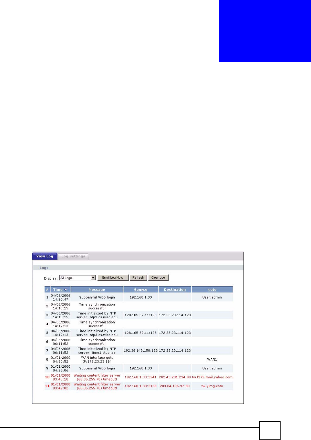
19.1 View Log
The web configurator allows you to look at all of the NBG318S’s logs in one location.
Click Maintenance > Logs to open the View Log screen.
Use the View Log screen to see the logs for the categories that you selected in the Log
Settings screen (see Section 19.2 on page 190). Options include logs about system
maintenance, system errors, access control, allowed or blocked web sites, blocked web
features (such as ActiveX controls, Java and cookies), attacks (such as DoS) and IPSec.
Log entries in red indicate system error logs. The log wraps around and deletes the old entries
after it fills. Click a column heading to sort the entries. A triangle indicates ascending or
descending sort order.
Figure 113 Maintenance > Logs > View Log
Chapter 19 Logs
NBG318S User’s Guide
190
The following table describes the labels in this screen.
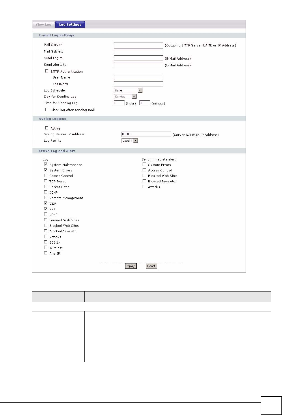
19.2 Log Settings
You can configure the NBG318S’s general log settings in one location.
Click Maintenance > Logs > Log Settings to open the Log Settings screen.
Use the Log Settings screen to configure to where the NBG318S is to send logs; the schedule
for when the NBG318S is to send the logs and which logs and/or immediate alerts the
NBG318S to send.
An alert is a type of log that warrants more serious attention. They include system errors,
attacks (access control) and attempted access to blocked web sites or web sites with restricted
web features such as cookies, active X and so on. Some categories such as System Errors
consist of both logs and alerts. You may differentiate them by their color in the View Log
screen. Alerts display in red and logs display in black.
Alerts are e-mailed as soon as they happen. Logs may be e-mailed as soon as the log is full
(see Log Schedule). Selecting many alert and/or log categories (especially Access Control)
may result in many e-mails being sent.
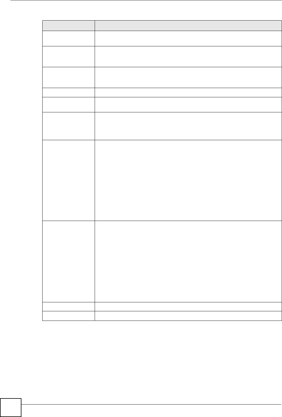
Table 71 Maintenance > Logs > View Log
LABEL DESCRIPTION
Display The categories that you select in the Log Settings page (see Section 19.2 on
page 190) display in the drop-down list box.
Select a category of logs to view; select All Logs to view logs from all of the log
categories that you selected in the Log Settings page.
Email Log Now Click Email Log Now to send the log screen to the e-mail address specified in
the Log Settings page (make sure that you have first filled in the Address Info
fields in Log Settings).
Refresh Click Refresh to renew the log screen.
Clear Log Click Clear Log to delete all the logs.
Time This field displays the time the log was recorded. See the chapter on system
maintenance and information to configure the NBG318S’s time and date.
Message This field states the reason for the log.
Source This field lists the source IP address and the port number of the incoming
packet.
Destination This field lists the destination IP address and the port number of the incoming
packet.
Note This field displays additional information about the log entry.
Chapter 19 Logs
NBG318S User’s Guide 191
Figure 114 Maintenance > Logs > Log Settings
The following table describes the labels in this screen.
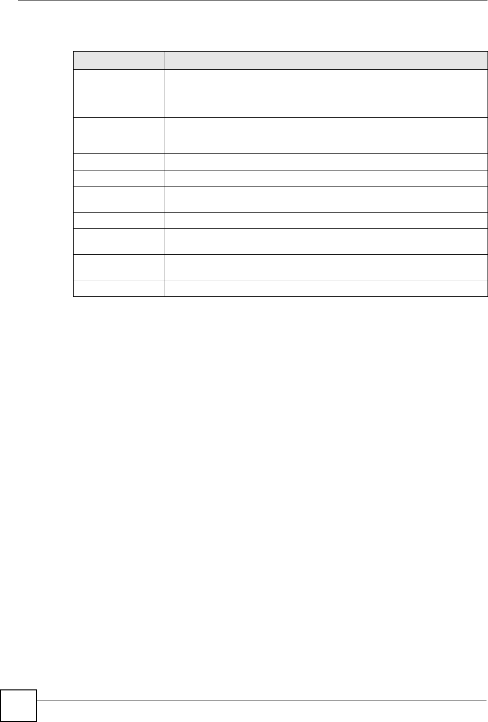
Table 72 Maintenance > Logs > Log Settings
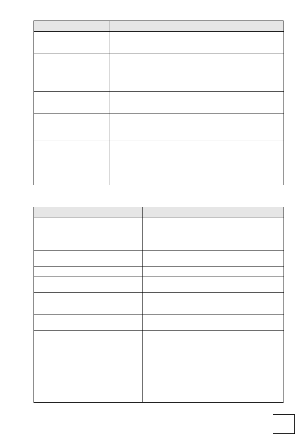
LABEL DESCRIPTION
E-mail Log Settings
Mail Server Enter the server name or the IP address of the mail server for the e-mail
addresses specified below. If this field is left blank, logs and alert messages will
not be sent via E-mail.
Mail Subject Type a title that you want to be in the subject line of the log e-mail message that
the NBG318S sends. Not all NBG318S models have this field.
Send Log To The NBG318S sends logs to the e-mail address specified in this field. If this
field is left blank, the NBG318S does not send logs via e-mail.
Chapter 19 Logs
NBG318S User’s Guide
192
Send Alerts To Alerts are real-time notifications that are sent as soon as an event, such as a
DoS attack, system error, or forbidden web access attempt occurs. Enter the E-
mail address where the alert messages will be sent. Alerts include system
errors, attacks and attempted access to blocked web sites. If this field is left
blank, alert messages will not be sent via E-mail.
SMTP
Authentication
SMTP (Simple Mail Transfer Protocol) is the message-exchange standard for
the Internet. SMTP enables you to move messages from one e-mail server to
another.
Select the check box to activate SMTP authentication. If mail server
authentication is needed but this feature is disabled, you will not receive the e-
mail logs.
User Name Enter the user name (up to 31 characters) (usually the user name of a mail
account).
Password Enter the password associated with the user name above.
Log Schedule This drop-down menu is used to configure the frequency of log messages being
sent as E-mail:
•Daily
•Weekly
• Hourly
• When Log is Full
• None.
If you select Weekly or Daily, specify a time of day when the E-mail should be
sent. If you select Weekly, then also specify which day of the week the E-mail
should be sent. If you select When Log is Full, an alert is sent when the log fills
up. If you select None, no log messages are sent.
Day for Sending Log Use the drop down list box to select which day of the week to send the logs.
Time for Sending
Log
Enter the time of the day in 24-hour format (for example 23:00 equals 11:00 pm)
to send the logs.
Clear log after
sending mail
Select the checkbox to delete all the logs after the NBG318S sends an E-mail of
the logs.
Syslog Logging The NBG318S sends a log to an external syslog server.
Active Click Active to enable syslog logging.
Syslog Server IP
Address
Enter the server name or IP address of the syslog server that will log the
selected categories of logs.
Log Facility Select a location from the drop down list box. The log facility allows you to log
the messages to different files in the syslog server. Refer to the syslog server
manual for more information.
Active Log and Alert
Log Select the categories of logs that you want to record.
Send Immediate
Alert
Select log categories for which you want the NBG318S to send E-mail alerts
immediately.
Apply Click Apply to save your changes.
Reset Click Reset to begin configuring this screen afresh.
Table 72 Maintenance > Logs > Log Settings
LABEL DESCRIPTION
Chapter 19 Logs
NBG318S User’s Guide 193
19.3 Log Descriptions
This section provides descriptions of example log messages.
Table 73 System Maintenance Logs
LOG MESSAGE DESCRIPTION
Time calibration is
successful
The router has adjusted its time based on information from
the time server.
Time calibration failed The router failed to get information from the time server.
WAN interface gets IP:%s A WAN interface got a new IP address from the DHCP,
PPPoE, PPTP or dial-up server.
DHCP client IP expired A DHCP client's IP address has expired.
DHCP server assigns%s The DHCP server assigned an IP address to a client.
Successful WEB login Someone has logged on to the router's web configurator
interface.
WEB login failed Someone has failed to log on to the router's web configurator
interface.
Successful TELNET login Someone has logged on to the router via telnet.
TELNET login failed Someone has failed to log on to the router via telnet.
Successful FTP login Someone has logged on to the router via ftp.
FTP login failed Someone has failed to log on to the router via ftp.
NAT Session Table is Full! The maximum number of NAT session table entries has been
exceeded and the table is full.
Starting Connectivity
Monitor
Starting Connectivity Monitor.
Time initialized by Daytime
Server
The router got the time and date from the Daytime server.
Time initialized by Time
server
The router got the time and date from the time server.
Time initialized by NTP
server
The router got the time and date from the NTP server.
Connect to Daytime server
fail
The router was not able to connect to the Daytime server.
Connect to Time server fail The router was not able to connect to the Time server.
Connect to NTP server fail The router was not able to connect to the NTP server.
Too large ICMP packet has
been dropped
The router dropped an ICMP packet that was too large.
Configuration Change: PC =
0x%x, Task ID = 0x%x
The router is saving configuration changes.
Successful SSH login Someone has logged on to the router’s SSH server.
SSH login failed Someone has failed to log on to the router’s SSH server.
Successful HTTPS login Someone has logged on to the router's web configurator
interface using HTTPS protocol.
HTTPS login failed Someone has failed to log on to the router's web configurator
interface using HTTPS protocol.
Chapter 19 Logs
NBG318S User’s Guide
194
Table 74 System Error Logs
LOG MESSAGE DESCRIPTION
%s exceeds the max.
number of session per
host!
This attempt to create a NAT session exceeds the maximum
number of NAT session table entries allowed to be created per
host.
setNetBIOSFilter: calloc
error
The router failed to allocate memory for the NetBIOS filter
settings.
readNetBIOSFilter: calloc
error
The router failed to allocate memory for the NetBIOS filter
settings.
WAN connection is down. A WAN connection is down. You cannot access the network
through this interface.
Table 75 Access Control Logs
LOG MESSAGE DESCRIPTION
Firewall default policy: [TCP |
UDP | IGMP | ESP | GRE | OSPF]
<Packet Direction>
Attempted TCP/UDP/IGMP/ESP/GRE/OSPF access
matched the default policy and was blocked or forwarded
according to the default policy’s setting.
Firewall rule [NOT] match:[TCP |
UDP | IGMP | ESP | GRE | OSPF]
<Packet Direction>, <rule:%d>
Attempted TCP/UDP/IGMP/ESP/GRE/OSPF access
matched (or did not match) a configured firewall rule
(denoted by its number) and was blocked or forwarded
according to the rule.
Triangle route packet forwarded:
[TCP | UDP | IGMP | ESP | GRE |
OSPF]
The firewall allowed a triangle route session to pass
through.
Packet without a NAT table entry
blocked: [TCP | UDP | IGMP | ESP
| GRE | OSPF]
The router blocked a packet that didn't have a
corresponding NAT table entry.
Router sent blocked web site
message: TCP
The router sent a message to notify a user that the router
blocked access to a web site that the user requested.
Table 76 TCP Reset Logs
LOG MESSAGE DESCRIPTION
Under SYN flood attack,
sent TCP RST
The router sent a TCP reset packet when a host was under a SYN
flood attack (the TCP incomplete count is per destination host.)
Exceed TCP MAX
incomplete, sent TCP RST
The router sent a TCP reset packet when the number of TCP
incomplete connections exceeded the user configured threshold.
(the TCP incomplete count is per destination host.) Note: Refer to
TCP Maximum Incomplete in the Firewall Attack Alerts screen.
Peer TCP state out of
order, sent TCP RST
The router sent a TCP reset packet when a TCP connection state
was out of order.Note: The firewall refers to RFC793 Figure 6 to
check the TCP state.
Chapter 19 Logs
NBG318S User’s Guide 195
Firewall session time
out, sent TCP RST
The router sent a TCP reset packet when a dynamic firewall
session timed out.
The default timeout values are as follows:
ICMP idle timeout: 3 minutes
UDP idle timeout: 3 minutes
TCP connection (three way handshaking) timeout: 270 seconds
TCP FIN-wait timeout: 2 MSL (Maximum Segment Lifetime set in
the TCP header).
TCP idle (established) timeout (s): 150 minutes
TCP reset timeout: 10 seconds
Exceed MAX incomplete,
sent TCP RST
The router sent a TCP reset packet when the number of
incomplete connections (TCP and UDP) exceeded the user-
configured threshold. (Incomplete count is for all TCP and UDP
connections through the firewall.)Note: When the number of
incomplete connections (TCP + UDP) > “Maximum Incomplete
High”, the router sends TCP RST packets for TCP connections
and destroys TOS (firewall dynamic sessions) until incomplete
connections < “Maximum Incomplete Low”.
Access block, sent TCP
RST
The router sends a TCP RST packet and generates this log if you
turn on the firewall TCP reset mechanism (via CI command: "sys
firewall tcprst").
Table 77 Packet Filter Logs
LOG MESSAGE DESCRIPTION
[TCP | UDP | ICMP | IGMP |
Generic] packet filter
matched (set:%d, rule:%d)
Attempted access matched a configured filter rule (denoted
by its set and rule number) and was blocked or forwarded
according to the rule.
Table 78 ICMP Logs
LOG MESSAGE DESCRIPTION
Firewall default policy: ICMP
<Packet Direction>, <type:%d>,
<code:%d>
ICMP access matched the default policy and was
blocked or forwarded according to the user's setting. For
type and code details, see Table 87 on page 200.
Firewall rule [NOT] match: ICMP
<Packet Direction>, <rule:%d>,
<type:%d>, <code:%d>
ICMP access matched (or didn’t match) a firewall rule
(denoted by its number) and was blocked or forwarded
according to the rule. For type and code details, see
Table 87 on page 200.
Triangle route packet forwarded:
ICMP
The firewall allowed a triangle route session to pass
through.
Packet without a NAT table entry
blocked: ICMP
The router blocked a packet that didn’t have a
corresponding NAT table entry.
Unsupported/out-of-order ICMP:
ICMP
The firewall does not support this kind of ICMP packets
or the ICMP packets are out of order.
Router reply ICMP packet: ICMP The router sent an ICMP reply packet to the sender.
Table 76 TCP Reset Logs (continued)
LOG MESSAGE DESCRIPTION
Chapter 19 Logs
NBG318S User’s Guide
196
Table 79 CDR Logs
LOG MESSAGE DESCRIPTION
board%d line%d channel%d,
call%d,%s C01 Outgoing Call
dev=%x ch=%x%s
The router received the setup requirements for a call. “call” is
the reference (count) number of the call. “dev” is the device
type (3 is for dial-up, 6 is for PPPoE, 10 is for PPTP).
"channel" or “ch” is the call channel ID.For example,"board 0
line 0 channel 0, call 3, C01 Outgoing Call dev=6 ch=0
"Means the router has dialed to the PPPoE server 3 times.
board%d line%d channel%d,
call%d,%s C02 OutCall
Connected%d%s
The PPPoE, PPTP or dial-up call is connected.
board%d line%d channel%d,
call%d,%s C02 Call
Terminated
The PPPoE, PPTP or dial-up call was disconnected.
Table 80 PPP Logs
LOG MESSAGE DESCRIPTION
ppp:LCP Starting The PPP connection’s Link Control Protocol stage has started.
ppp:LCP Opening The PPP connection’s Link Control Protocol stage is opening.
ppp:CHAP Opening The PPP connection’s Challenge Handshake Authentication Protocol stage is
opening.
ppp:IPCP
Starting
The PPP connection’s Internet Protocol Control Protocol stage is starting.
ppp:IPCP Opening The PPP connection’s Internet Protocol Control Protocol stage is opening.
ppp:LCP Closing The PPP connection’s Link Control Protocol stage is closing.
ppp:IPCP Closing The PPP connection’s Internet Protocol Control Protocol stage is closing.
Table 81 UPnP Logs
LOG MESSAGE DESCRIPTION
UPnP pass through Firewall UPnP packets can pass through the firewall.
Table 82 Content Filtering Logs
LOG MESSAGE DESCRIPTION
%s: Keyword blocking The content of a requested web page matched a user defined
keyword.
%s: Not in trusted web
list
The web site is not in a trusted domain, and the router blocks all traffic
except trusted domain sites.
%s: Forbidden Web site The web site is in the forbidden web site list.
%s: Contains ActiveX The web site contains ActiveX.
%s: Contains Java
applet
The web site contains a Java applet.
%s: Contains cookie The web site contains a cookie.
Chapter 19 Logs
NBG318S User’s Guide 197
%s: Proxy mode
detected
The router detected proxy mode in the packet.
%s The content filter server responded that the web site is in the blocked
category list, but it did not return the category type.
%s:%s The content filter server responded that the web site is in the blocked
category list, and returned the category type.
%s(cache hit) The system detected that the web site is in the blocked list from the
local cache, but does not know the category type.
%s:%s(cache hit) The system detected that the web site is in blocked list from the local
cache, and knows the category type.
%s: Trusted Web site The web site is in a trusted domain.
%s When the content filter is not on according to the time schedule or you
didn't select the "Block Matched Web Site” check box, the system
forwards the web content.
Waiting content filter
server timeout
The external content filtering server did not respond within the timeout
period.
DNS resolving failed The NBG318S cannot get the IP address of the external content
filtering via DNS query.
Creating socket failed The NBG318S cannot issue a query because TCP/IP socket creation
failed, port:port number.
Connecting to content
filter server fail
The connection to the external content filtering server failed.
License key is invalid The external content filtering license key is invalid.
Table 83 Attack Logs
LOG MESSAGE DESCRIPTION
attack [TCP | UDP | IGMP
| ESP | GRE | OSPF]
The firewall detected a TCP/UDP/IGMP/ESP/GRE/OSPF attack.
attack ICMP (type:%d,
code:%d)
The firewall detected an ICMP attack. For type and code details,
see Table 87 on page 200.
land [TCP | UDP | IGMP |
ESP | GRE | OSPF]
The firewall detected a TCP/UDP/IGMP/ESP/GRE/OSPF land
attack.
land ICMP (type:%d,
code:%d)
The firewall detected an ICMP land attack. For type and code
details, see Table 87 on page 200.
ip spoofing - WAN [TCP |
UDP | IGMP | ESP | GRE |
OSPF]
The firewall detected an IP spoofing attack on the WAN port.
ip spoofing - WAN ICMP
(type:%d, code:%d)
The firewall detected an ICMP IP spoofing attack on the WAN
port. For type and code details, see Table 87 on page 200.
icmp echo: ICMP (type:%d,
code:%d)
The firewall detected an ICMP echo attack. For type and code
details, see Table 87 on page 200.
syn flood TCP The firewall detected a TCP syn flood attack.
ports scan TCP The firewall detected a TCP port scan attack.
teardrop TCP The firewall detected a TCP teardrop attack.
Table 82 Content Filtering Logs (continued)
LOG MESSAGE DESCRIPTION
Chapter 19 Logs
NBG318S User’s Guide
198
teardrop UDP The firewall detected an UDP teardrop attack.
teardrop ICMP (type:%d,
code:%d)
The firewall detected an ICMP teardrop attack. For type and code
details, see Table 87 on page 200.
illegal command TCP The firewall detected a TCP illegal command attack.
NetBIOS TCP The firewall detected a TCP NetBIOS attack.
ip spoofing - no routing
entry [TCP | UDP | IGMP |
ESP | GRE | OSPF]
The firewall classified a packet with no source routing entry as an
IP spoofing attack.
ip spoofing - no routing
entry ICMP (type:%d,
code:%d)
The firewall classified an ICMP packet with no source routing
entry as an IP spoofing attack.
vulnerability ICMP
(type:%d, code:%d)
The firewall detected an ICMP vulnerability attack. For type and
code details, see Table 87 on page 200.
traceroute ICMP (type:%d,
code:%d)
The firewall detected an ICMP traceroute attack. For type and
code details, see Table 87 on page 200.
Table 84 PKI Logs
LOG MESSAGE DESCRIPTION
Enrollment successful The SCEP online certificate enrollment was successful. The
Destination field records the certification authority server IP address
and port.
Enrollment failed The SCEP online certificate enrollment failed. The Destination field
records the certification authority server’s IP address and port.
Failed to resolve
<SCEP CA server url>
The SCEP online certificate enrollment failed because the certification
authority server’s address cannot be resolved.
Enrollment successful The CMP online certificate enrollment was successful. The Destination
field records the certification authority server’s IP address and port.
Enrollment failed The CMP online certificate enrollment failed. The Destination field
records the certification authority server’s IP address and port.
Failed to resolve <CMP
CA server url>
The CMP online certificate enrollment failed because the certification
authority server’s IP address cannot be resolved.
Rcvd ca cert: <subject
name>
The router received a certification authority certificate, with subject
name as recorded, from the LDAP server whose IP address and port
are recorded in the Source field.
Rcvd user cert:
<subject name>
The router received a user certificate, with subject name as recorded,
from the LDAP server whose IP address and port are recorded in the
Source field.
Rcvd CRL <size>:
<issuer name>
The router received a CRL (Certificate Revocation List), with size and
issuer name as recorded, from the LDAP server whose IP address and
port are recorded in the Source field.
Rcvd ARL <size>:
<issuer name>
The router received an ARL (Authority Revocation List), with size and
issuer name as recorded, from the LDAP server whose address and
port are recorded in the Source field.
Table 83 Attack Logs (continued)
LOG MESSAGE DESCRIPTION
Chapter 19 Logs
NBG318S User’s Guide 199
Failed to decode the
received ca cert
The router received a corrupted certification authority certificate from
the LDAP server whose address and port are recorded in the Source
field.
Failed to decode the
received user cert
The router received a corrupted user certificate from the LDAP server
whose address and port are recorded in the Source field.
Failed to decode the
received CRL
The router received a corrupted CRL (Certificate Revocation List) from
the LDAP server whose address and port are recorded in the Source
field.
Failed to decode the
received ARL
The router received a corrupted ARL (Authority Revocation List) from
the LDAP server whose address and port are recorded in the Source
field.
Rcvd data <size> too
large! Max size
allowed: <max size>
The router received directory data that was too large (the size is listed)
from the LDAP server whose address and port are recorded in the
Source field. The maximum size of directory data that the router allows
is also recorded.
Cert trusted: <subject
name>
The router has verified the path of the certificate with the listed subject
name.
Due to <reason codes>,
cert not trusted:
<subject name>
Due to the reasons listed, the certificate with the listed subject name
has not passed the path verification. The recorded reason codes are
only approximate reasons for not trusting the certificate. Please see
Table 87 on page 200 for the corresponding descriptions of the codes.
Table 85 802.1X Logs
LOG MESSAGE DESCRIPTION
Local User Database accepts
user.
A user was authenticated by the local user database.
Local User Database reports user
credential error.
A user was not authenticated by the local user database
because of an incorrect user password.
Local User Database does not
find user`s credential.
A user was not authenticated by the local user database
because the user is not listed in the local user database.
RADIUS accepts user. A user was authenticated by the RADIUS Server.
RADIUS rejects user. Pls check
RADIUS Server.
A user was not authenticated by the RADIUS Server.
Please check the RADIUS Server.
Local User Database does not
support authentication method.
The local user database only supports the EAP-MD5
method. A user tried to use another authentication
method and was not authenticated.
User logout because of session
timeout expired.
The router logged out a user whose session expired.
User logout because of user
deassociation.
The router logged out a user who ended the session.
User logout because of no
authentication response from
user.
The router logged out a user from which there was no
authentication response.
User logout because of idle
timeout expired.
The router logged out a user whose idle timeout period
expired.
User logout because of user
request.
A user logged out.
Table 84 PKI Logs (continued)
LOG MESSAGE DESCRIPTION
Chapter 19 Logs
NBG318S User’s Guide
200
Local User Database does not
support authentication method.
A user tried to use an authentication method that the
local user database does not support (it only supports
EAP-MD5).
No response from RADIUS. Pls
check RADIUS Server.
There is no response message from the RADIUS server,
please check the RADIUS server.
Use Local User Database to
authenticate user.
The local user database is operating as the
authentication server.
Use RADIUS to authenticate user. The RADIUS server is operating as the authentication
server.
No Server to authenticate user. There is no authentication server to authenticate a user.
Local User Database does not
find user`s credential.
A user was not authenticated by the local user database
because the user is not listed in the local user database.
Table 86 ACL Setting Notes
PACKET DIRECTION DIRECTION DESCRIPTION
(L to W) LAN to WAN ACL set for packets traveling from the LAN to the WAN.
(W to L) WAN to LAN ACL set for packets traveling from the WAN to the LAN.
(L to L/P) LAN to LAN/
NBG318S
ACL set for packets traveling from the LAN to the LAN or
the NBG318S.
(W to W/P) WAN to WAN/
NBG318S
ACL set for packets traveling from the WAN to the WAN
or the NBG318S.
Table 87 ICMP Notes
TYPE CODE DESCRIPTION
0Echo Reply
0Echo reply message
3Destination Unreachable
0Net unreachable
1Host unreachable
2Protocol unreachable
3Port unreachable
4A packet that needed fragmentation was dropped because it was set to Don't
Fragment (DF)
5Source route failed
4Source Quench
0A gateway may discard internet datagrams if it does not have the buffer space
needed to queue the datagrams for output to the next network on the route to
the destination network.
5Redirect
0Redirect datagrams for the Network
1Redirect datagrams for the Host
Table 85 802.1X Logs (continued)
LOG MESSAGE DESCRIPTION
Chapter 19 Logs
NBG318S User’s Guide 201
The following table shows RFC-2408 ISAKMP payload types that the log displays. Please
refer to the RFC for detailed information on each type.
2Redirect datagrams for the Type of Service and Network
3Redirect datagrams for the Type of Service and Host
8Echo
0Echo message
11 Time Exceeded
0Time to live exceeded in transit
1Fragment reassembly time exceeded
12 Parameter Problem
0Pointer indicates the error
13 Timestamp
0Timestamp request message
14 Timestamp Reply
0Timestamp reply message
15 Information Request
0Information request message
16 Information Reply
0Information reply message
Table 88 Syslog Logs
LOG MESSAGE DESCRIPTION
<Facility*8 + Severity>Mon dd
hr:mm:ss hostname
src="<srcIP:srcPort>"
dst="<dstIP:dstPort>"
msg="<msg>" note="<note>"
devID="<mac address last three
numbers>" cat="<category>
"This message is sent by the system ("RAS" displays as
the system name if you haven’t configured one) when the
router generates a syslog. The facility is defined in the web
MAIN MENU->LOGS->Log Settings page. The severity is
the log’s syslog class. The definition of messages and
notes are defined in the various log charts throughout this
appendix. The “devID” is the last three characters of the
MAC address of the router’s LAN port. The “cat” is the
same as the category in the router’s logs.
Table 89 RFC-2408 ISAKMP Payload Types
LOG DISPLAY PAYLOAD TYPE
SA Security Association
PROP Proposal
TRANS Transform
KE Key Exchange
ID Identification
CER Certificate
CER_REQ Certificate Request
HASH Hash
Table 87 ICMP Notes (continued)
TYPE CODE DESCRIPTION
Chapter 19 Logs
NBG318S User’s Guide
202
SIG Signature
NONCE Nonce
NOTFY Notification
DEL Delete
VID Vendor ID
Table 89 RFC-2408 ISAKMP Payload Types (continued)
LOG DISPLAY PAYLOAD TYPE
NBG318S User’s Guide 203
CHAPTER 20
Tools
This chapter shows you how to upload a new firmware, upload or save backup configuration
files and restart the NBG318S.
20.1 Firmware Upload Screen
Find firmware at www.zyxel.com in a file that (usually) uses the system model name with a
"*.bin" extension, e.g., “NBG318S.bin". The upload process uses HTTP (Hypertext Transfer
Protocol) and may take up to two minutes. After a successful upload, the system will reboot.
See the Firmware and Configuration File Maintenance chapter for upgrading firmware using
FTP/TFTP commands.
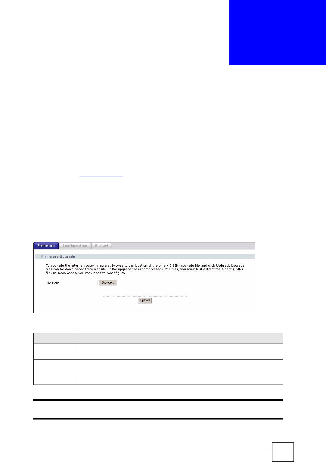
Click Maintenance > Tools. Follow the instructions in this screen to upload firmware to your
NBG318S.
Figure 115 Maintenance > Tools > Firmware
The following table describes the labels in this screen.
"Do not turn off the NBG318S while firmware upload is in progress!
Table 90 Maintenance > Tools > Firmware
LABEL DESCRIPTION
File Path Type in the location of the file you want to upload in this field or click Browse... to find
it.
Browse... Click Browse... to find the .bin file you want to upload. Remember that you must
decompress compressed (.zip) files before you can upload them.
Upload Click Upload to begin the upload process. This process may take up to two minutes.
Chapter 20 Tools
NBG318S User’s Guide
204
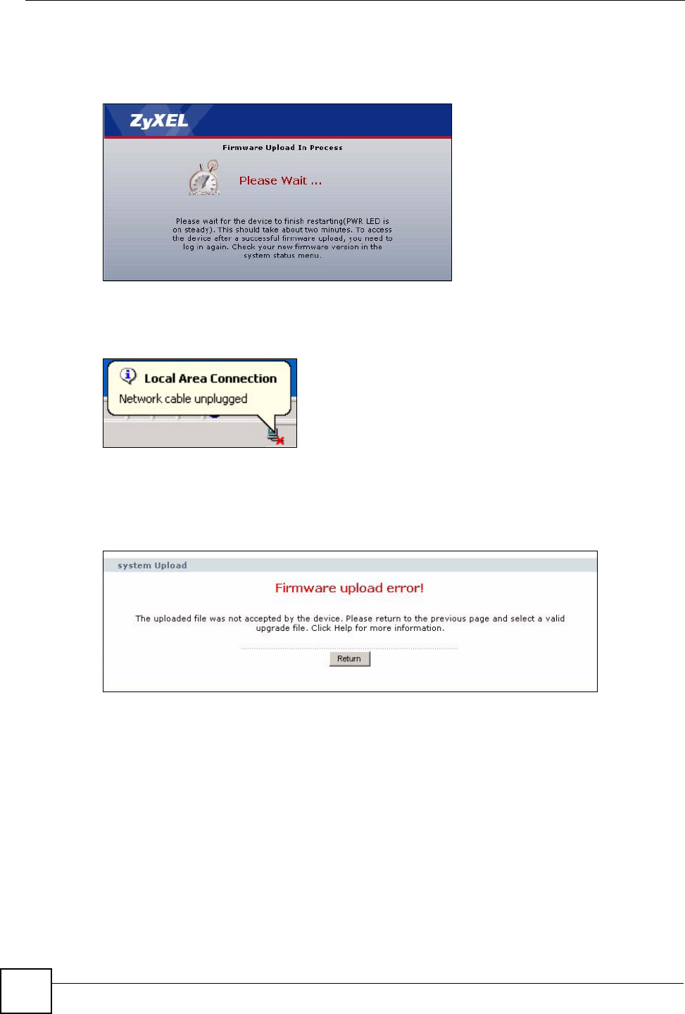
After you see the Firmware Upload In Process screen, wait two minutes before logging into
the NBG318S again.
Figure 116 Upload Warning
The NBG318S automatically restarts in this time causing a temporary network disconnect. In
some operating systems, you may see the following icon on your desktop.
Figure 117 Network Temporarily Disconnected
After two minutes, log in again and check your new firmware version in the Status screen.
If the upload was not successful, the following screen will appear. Click Return to go back to
the Firmware screen.
Figure 118 Upload Error Message
20.2 Configuration Screen
See the Firmware and Configuration File Maintenance chapter for transferring configuration
files using FTP/TFTP commands.
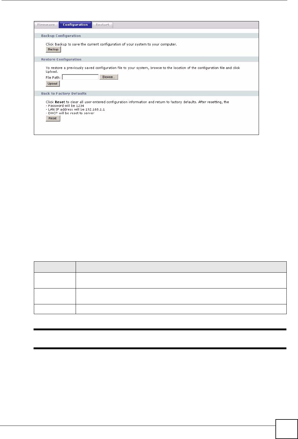
Click Maintenance > Tools > Configuration. Information related to factory defaults, backup
configuration, and restoring configuration appears as shown next.
Chapter 20 Tools
NBG318S User’s Guide 205
Figure 119 Maintenance > Tools > Configuration
20.2.1 Backup Configuration
Backup configuration allows you to back up (save) the NBG318S’s current configuration to a
file on your computer. Once your NBG318S is configured and functioning properly, it is
highly recommended that you back up your configuration file before making configuration
changes. The backup configuration file will be useful in case you need to return to your
previous settings.
Click Backup to save the NBG318S’s current configuration to your computer.
20.2.2 Restore Configuration
Restore configuration allows you to upload a new or previously saved configuration file from
your computer to your NBG318S.
"Do not turn off the NBG318S while configuration file upload is in progress
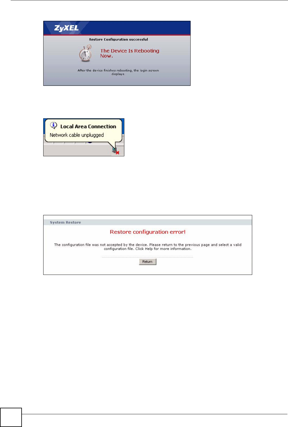
After you see a “configuration upload successful” screen, you must then wait one minute
before logging into the NBG318S again.
Table 91 Maintenance Restore Configuration
LABEL DESCRIPTION
File Path Type in the location of the file you want to upload in this field or click Browse... to find
it.
Browse... Click Browse... to find the file you want to upload. Remember that you must
decompress compressed (.ZIP) files before you can upload them.
Upload Click Upload to begin the upload process.
Chapter 20 Tools
NBG318S User’s Guide
206
Figure 120 Configuration Restore Successful
The NBG318S automatically restarts in this time causing a temporary network disconnect. In
some operating systems, you may see the following icon on your desktop.
Figure 121 Temporarily Disconnected
If you uploaded the default configuration file you may need to change the IP address of your
computer to be in the same subnet as that of the default NBG318S IP address (192.168.1.1).
See your Quick Start Guide for details on how to set up your computer’s IP address.
If the upload was not successful, the following screen will appear. Click Return to go back to
the Configuration screen.
Figure 122 Configuration Restore Error
20.2.3 Back to Factory Defaults
Pressing the Reset button in this section clears all user-entered configuration information and
returns the NBG318S to its factory defaults.
You can also press the RESET button on the rear panel to reset the factory defaults of your
NBG318S. Refer to the chapter about introducing the web configurator for more information
on the RESET button.
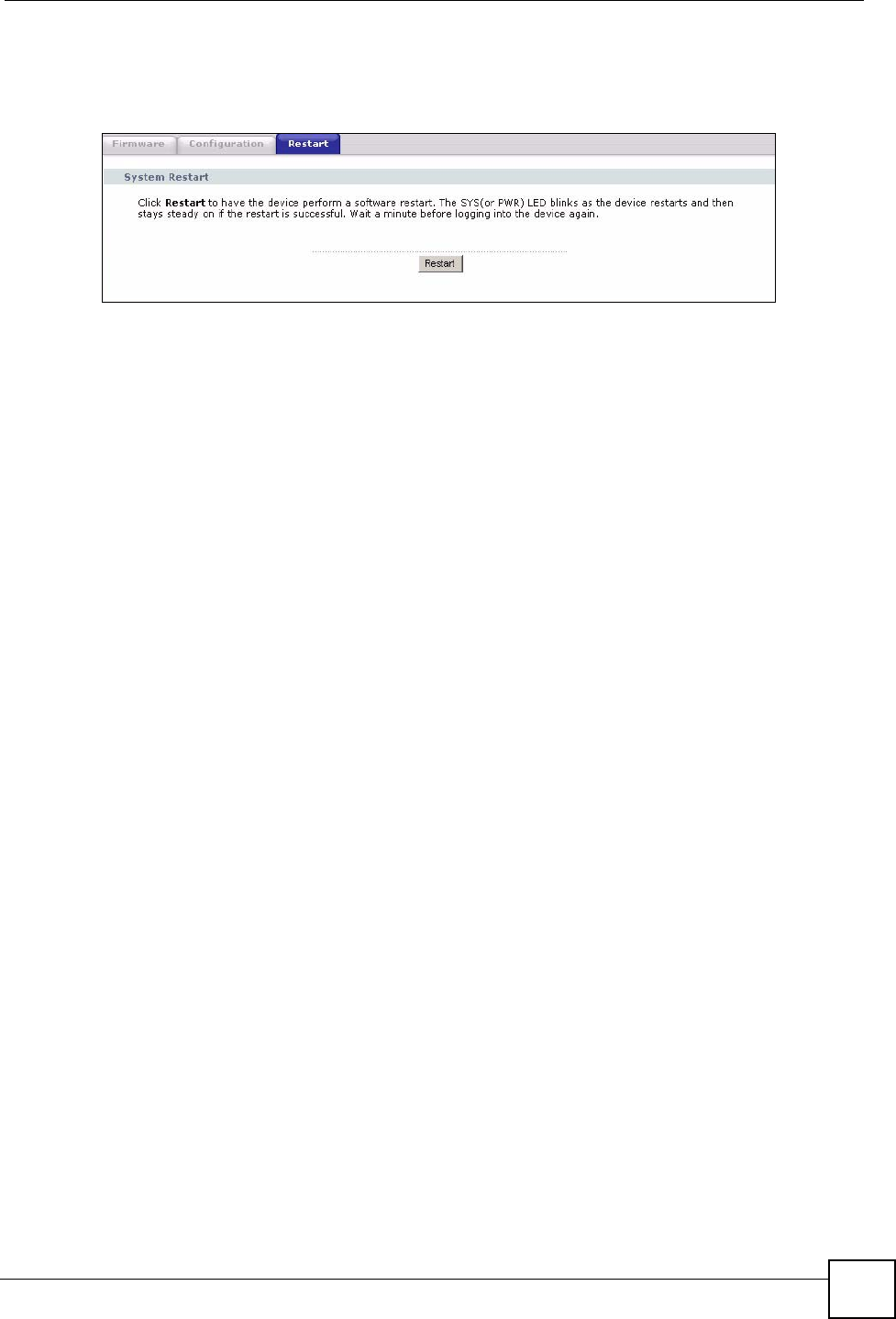
20.3 Restart Screen
System restart allows you to reboot the NBG318S without turning the power off.
Chapter 20 Tools
NBG318S User’s Guide 207
Click Maintenance > Tools > Restart. Click Restart to have the NBG318S reboot. This does
not affect the NBG318S's configuration.
Figure 123 Maintenance > Tools > Restart

Chapter 20 Tools
NBG318S User’s Guide
208
NBG318S User’s Guide 209
CHAPTER 21
Configuration Mode
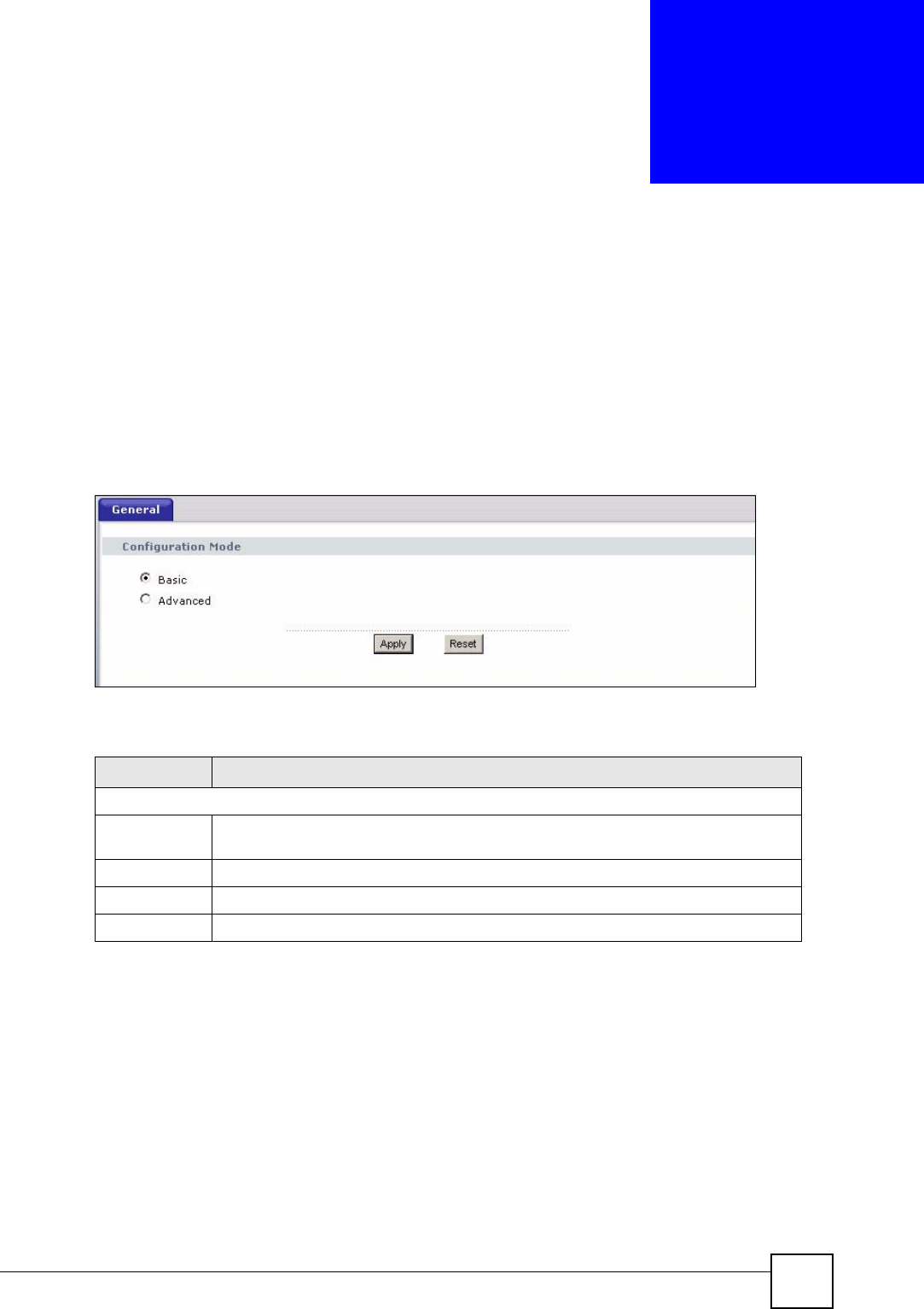
Click Maintenance > Config Mode to open the following screen. This screen allows you to
hide or display the advanced screens of some features or the advanced features, such as MAC
filter or static route. Basic is selected by default and you cannot see the advanced screens or
features. If you want to view and configure all screens including the advanced ones, select
Advanced and click Apply.
Figure 124 Maintenance > Config Mode > General
The following table describes the labels in the screen.
Table 92 Maintenance > Config Mode > General
The following table includes the screens that you can view and configure only when you select
Advanced.
LABEL DESCRIPTION
Configuration Mode
Basic Select Basic mode to enable or disable features and to monitor the status of your
device.
Advanced Select Advanced mode to set advanced settings.
Apply Click on this to set the mode.
Reset Click on this to reset your selection to the default (Advanced).
Chapter 21 Configuration Mode
NBG318S User’s Guide
210
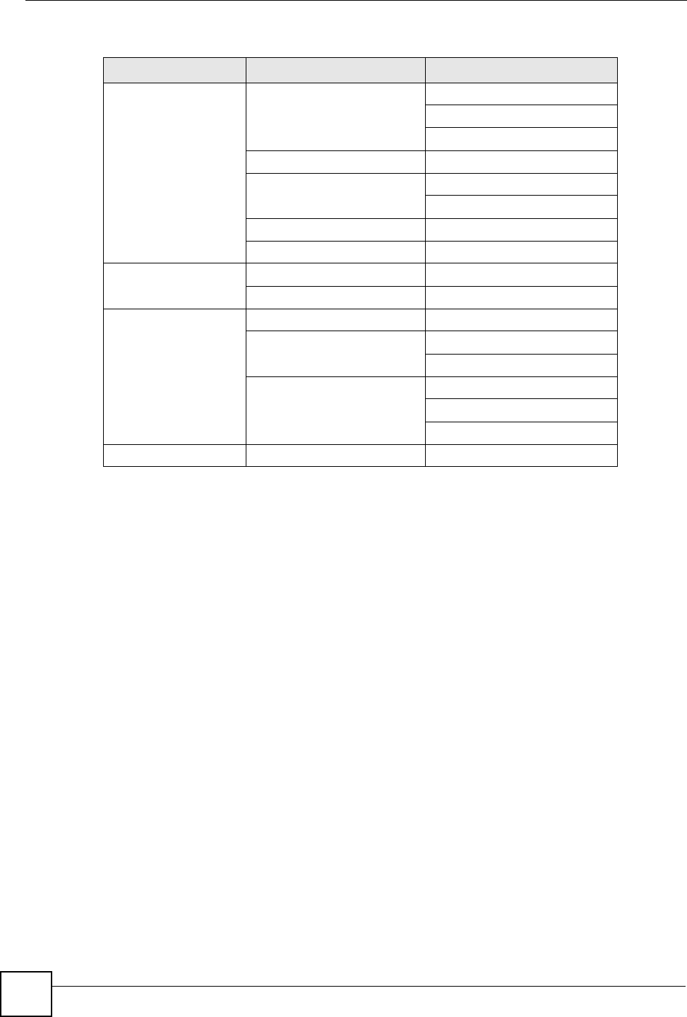
Table 93 Advanced Configuration Options
CATEGORY LINK TAB
Network Wireless LAN MAC Filter
Advanced
QoS
WAN Advanced
LAN IP Alias
Advanced
DHCP Server Advanced
NAT Advanced
Security Firewall Services
Content Filter Schedule
Management Static Route IP Static Route
Bandwidth MGMT Advanced
Monitor
Remote MGMT Telnet
FTP
DNS
Maintenance Logs Log Settings
NBG318S User’s Guide 211
CHAPTER 22
Sys Op Mode
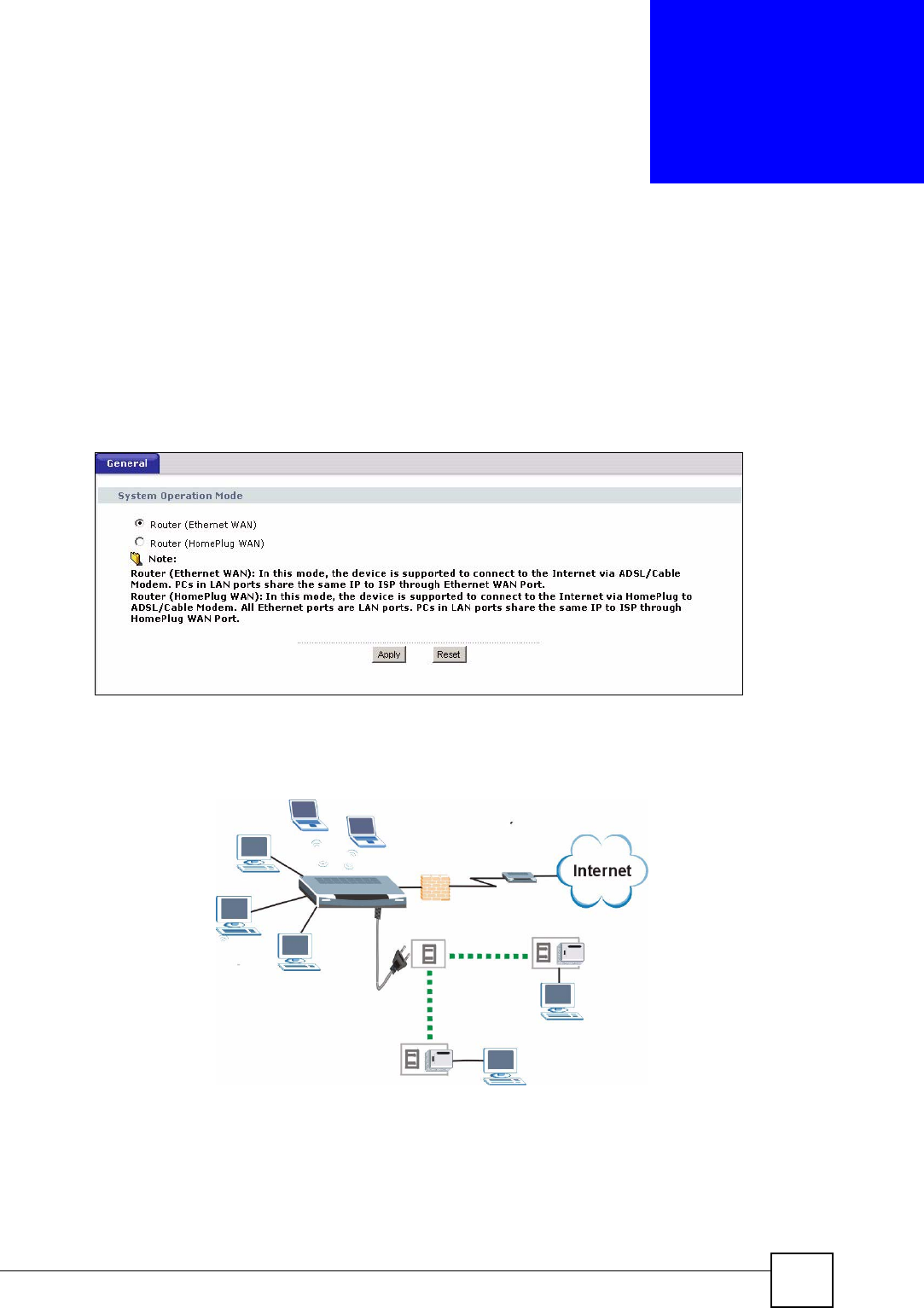
22.1 Selecting System Operation Mode
Use this screen to select how you connect to the Internet.
Figure 125 Maintenance > Sys OP Mode > General
The figure below shows devices connecting to the Internet through a DSL connection. Select
Router(Ethernet WAN) in the screen if you connect to the Internet as shown in diagram.
Figure 126 System Operation Mode: Ethernet WAN
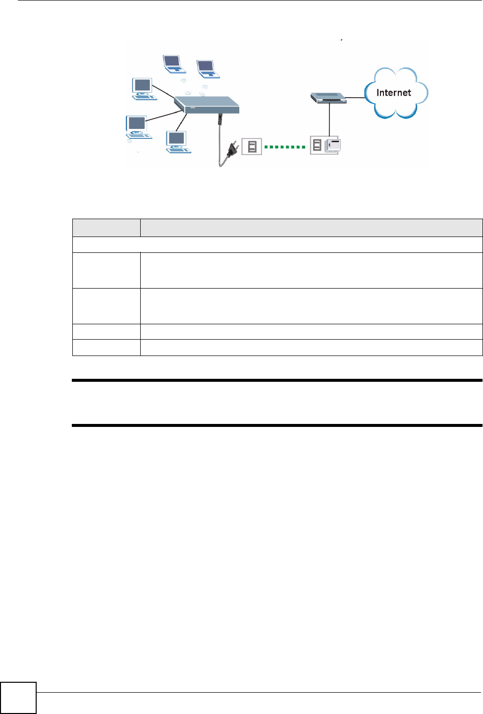
The figure below shows a network connecting to the Internet through a HomePlug connection.
Select Router(HomePlug WAN) in the screen if you connect to the Internet as shown in the
diagram.
Chapter 22 Sys Op Mode
NBG318S User’s Guide
212
Figure 127 System Operation Mode: HomePlug WAN
The following table describes the labels in the screen.
Table 94 Maintenance > Sys OP Mode > General
"If you select the incorrect System Operation Mode you cannot connect to the
Internet.
LABEL DESCRIPTION
System Operation Mode
Router
(Ethernet
WAN)
Select this option if you connect to the Internet through a DSL or cable connection. In
this mode three of the four ports are LAN ports, the other is a WAN port.
Router
(HomePlug
WAN)
Select this option if you connect to the Internet through a DSL or cable modem
connected to your HomePlug AV network. In this mode all four of your ports operate
as LAN ports.
Apply Click this button to apply your settings.
Reset Click this button to reset your settings to the default (Ethernet WAN)

NBG318S User’s Guide 213
CHAPTER 23
Troubleshooting
This chapter offers some suggestions to solve problems you might encounter. The potential
problems are divided into the following categories.
•Power, Hardware Connections, and LEDs
•NBG318S Access and Login
•Internet Access
•Resetting the NBG318S to Its Factory Defaults
•Wireless Router/AP Troubleshooting
•HomePlug AV Troubleshooting
•Advanced Features
23.1 Power, Hardware Connections, and LEDs
VThe NBG318S does not turn on. None of the LEDs turn on.
1Make sure you are using the power adaptor or cord included with the NBG318S.
2Make sure the power adaptor or cord is connected to the NBG318S and plugged in to an
appropriate power source. Make sure the power source is turned on.
3Disconnect and re-connect the power adaptor or cord to the NBG318S.
4If the problem continues, contact the vendor.
VOne of the LEDs does not behave as expected.
1Make sure you understand the normal behavior of the LED. See Section 1.4 on page 33.
2Check the hardware connections. See the Quick Start Guide.
3Inspect your cables for damage. Contact the vendor to replace any damaged cables.
4Disconnect and re-connect the power adaptor to the NBG318S.
5If the problem continues, contact the vendor.

Chapter 23 Troubleshooting
NBG318S User’s Guide
214
23.2 NBG318S Access and Login
VI forgot the IP address for the NBG318S.
1The default IP address is 192.168.1.1.
2If you changed the IP address and have forgotten it, you might get the IP address of the
NBG318S by looking up the IP address of the default gateway for your computer. To do
this in most Windows computers, click Start > Run, enter cmd, and then enter ipconfig.
The IP address of the Default Gateway might be the IP address of the NBG318S (it
depends on the network), so enter this IP address in your Internet browser.
3If this does not work, you have to reset the device to its factory defaults. See Section
23.4 on page 217.
VI forgot the password.
1The default password is 1234.
2If this does not work, you have to reset the device to its factory defaults. See Section
23.4 on page 217.
VI cannot see or access the Login screen in the web configurator.
1Make sure you are using the correct IP address.
• The default IP address is 192.168.1.1.
• If you changed the IP address (Section 7.3 on page 106), use the new IP address.
• If you changed the IP address and have forgotten it, see the troubleshooting
suggestions for I forgot the IP address for the NBG318S.
2Check the hardware connections, and make sure the LEDs are behaving as expected. See
the Quick Start Guide.
3Make sure your Internet browser does not block pop-up windows and has JavaScripts
and Java enabled. See Appendix B on page 229.
4Make sure your computer is in the same subnet as the NBG318S. (If you know that there
are routers between your computer and the NBG318S, skip this step.)
• If there is a DHCP server on your network, make sure your computer is using a
dynamic IP address. See Section 7.3 on page 106. Your NBG318S is a DHCP server
by default.
• If there is no DHCP server on your network, make sure your computer’s IP address is
in the same subnet as the NBG318S. See Section 7.3 on page 106.
5Reset the device to its factory defaults, and try to access the NBG318S with the default
IP address. See Section 7.3 on page 106.

Chapter 23 Troubleshooting
NBG318S User’s Guide 215
6If the problem continues, contact the network administrator or vendor, or try one of the
advanced suggestions.
Advanced Suggestions
• Try to access the NBG318S using another service, such as Telnet. If you can access the
NBG318S, check the remote management settings and firewall rules to find out why the
NBG318S does not respond to HTTP.
• If your computer is connected to the WAN port or is connected wirelessly, use a computer
that is connected to a LAN/ETHERNET port.
VI can see the Login screen, but I cannot log in to the NBG318S.
1Make sure you have entered the password correctly. The default password is 1234. This
field is case-sensitive, so make sure [Caps Lock] is not on.
2You cannot log in to the web configurator while someone is using Telnet to access the
NBG318S. Log out of the NBG318S in the other session, or ask the person who is
logged in to log out.
3Disconnect and re-connect the power adaptor or cord to the NBG318S.
4If this does not work, you have to reset the device to its factory defaults. See Section
23.4 on page 217.
VI cannot Telnet to the NBG318S.
See the troubleshooting suggestions for I cannot see or access the Login screen in the web
configurator. Ignore the suggestions about your browser.
VI cannot use FTP to upload / download the configuration file. / I cannot use
FTP to upload new firmware.
See the troubleshooting suggestions for I cannot see or access the Login screen in the web
configurator. Ignore the suggestions about your browser.
23.3 Internet Access
VI cannot access the Internet.

Chapter 23 Troubleshooting
NBG318S User’s Guide
216
1Check the hardware connections, and make sure the LEDs are behaving as expected. See
the Quick Start Guide.
2Make sure you entered your ISP account information correctly in the wizard. These
fields are case-sensitive, so make sure [Caps Lock] is not on.
3If you are trying to access the Internet wirelessly, make sure the wireless settings in the
wireless client are the same as the settings in the AP.
4Disconnect all the cables from your device, and follow the directions in the Quick Start
Guide again.
5Go to Maintenance > Sys OP Mode > General. Check your System Operation Mode
setting.
• Select Router (Ethernet WAN) if your network is configured to access the Internet
through an Ethernet connection to a DSL or cable modem.
• Select Router (HomePlug WAN) if your network is configured to access the Internet
through a HomePlug connection.
6If the problem continues, contact your ISP.
VI cannot access the Internet anymore. I had access to the Internet (with the
NBG318S), but my Internet connection is not available anymore.
1Check the hardware connections, and make sure the LEDs are behaving as expected. See
the Quick Start Guide and Section 1.4 on page 33.
2Reboot the NBG318S.
3If the problem continues, contact your ISP.
VThe Internet connection is slow or intermittent.
1There might be a lot of traffic on the network. Look at the LEDs, and check Section 1.4
on page 33. If the NBG318S is sending or receiving a lot of information, try closing
some programs that use the Internet, especially peer-to-peer applications.
2Check the signal strength. If the signal strength is low, try moving the NBG318S closer
to the AP if possible, and look around to see if there are any devices that might be
interfering with the wireless network (for example, microwaves, other wireless
networks, and so on).
3Reboot the NBG318S.
4If the problem continues, contact the network administrator or vendor, or try one of the
advanced suggestions.
Advanced Suggestions
• Check the settings for bandwidth management. If it is disabled, you might consider
activating it. If it is enabled, you might consider changing the allocations.
• Check the settings for QoS. If it is disabled, you might consider activating it. If it is
enabled, you might consider raising or lowering the priority for some applications.

Chapter 23 Troubleshooting
NBG318S User’s Guide 217
23.4 Resetting the NBG318S to Its Factory Defaults
If you reset the NBG318S, you lose all of the changes you have made. The NBG318S re-loads
its default settings, and the password resets to 1234. You have to make all of your changes
again.
VYou will lose all of your changes when you push the RESET button.
To reset the NBG318S,
1Make sure the PWR LED is on and not blinking.
2Press and hold the RESET button for five to ten seconds. Release the RESET button
when the PWR LED begins to blink. The default settings have been restored.
If the NBG318S restarts automatically, wait for the NBG318S to finish restarting, and log in to
the web configurator. The password is “1234”.
If the NBG318S does not restart automatically, disconnect and reconnect the NBG318S’s
power. Then, follow the directions above again.
23.5 Wireless Router/AP Troubleshooting
VI cannot access the NBG318S or ping any computer from the WLAN (wireless
AP or router).
1Make sure the wireless LAN is enabled on the NBG318S
2Make sure the wireless adapter on the wireless station is working properly.
3Make sure the wireless adapter installed on your computer is IEEE 802.11 compatible
and supports the same wireless standard as the NBG318S.
4Make sure your computer (with a wireless adapter installed) is within the transmission
range of the NBG318S.
5Check that both the NBG318S and your wireless station are using the same wireless and
wireless security settings.
6Make sure traffic between the WLAN and the LAN is not blocked by the firewall on the
NBG318S.
7Make sure you allow the NBG318S to be remotely accessed through the WLAN
interface. Check your remote management settings.
• See the chapter on Wireless LAN in the User’s Guide for more information.
Chapter 23 Troubleshooting
NBG318S User’s Guide
218
23.6 HomePlug AV Troubleshooting
VI cannot start my power line device.
Check your power supply is working. Power line adapters operate from the power supplied by
your home wiring and cannot operate without a working power supply. Remove the power line
adapter from the outlet. Then connect an electrical device that you know works into the same
power outlet. This checks the status of the power outlet.
VI cannot access my power line network.
1Make sure that the network password is the same on all the power line adapters in your
network.
2Check the DAK and MAC address for all power line adapters are typed correctly.
3Make sure that all your power line adapters are HomePlug AV. Check the package it
came in or ask your vendor. This NBG318S can not detect earlier versions of HomePlug
power line adapters such as HomePlug 1.0 or 1.0.1. (Although they can coexist on the
same electrical wiring without interfering with each other.)
4Make sure that the devices on your network are all on the same electrical wiring.
Connect another power line adapter into an outlet close to your NBG318S’s power
outlet. They are probably now on the same electrical wiring. Check the Link LED. If
it now lights up your power line adapter was probably previously on separate electrical
wiring. Ask an electrician for more information on the electrical wiring in your building.
5Check you do not have a power meter between power line adapters. Power line signals
cannot pass this.
VThe signal on my power line network may be weak for the following reasons.
1Your power line adapters may be connected to electrical surge protectors. Connect them
to standard power outlets.
2Your power line adapters may be located close to large appliances such as refrigerators
or air-conditioners that cause interference with the power line signal. Move the adapters
further away from such appliances to reduce interference.
3Your power line adapters may be placed close to electrical devices such as electrical
insect-killers which produce radio waves. These may interfere with the power line
signals. Move the adapters further away from such electrical devices.
4Your wiring may be old and/or low quality or with a long wiring path.

Chapter 23 Troubleshooting
NBG318S User’s Guide 219
23.7 Advanced Features
VI can log in, but I cannot see some of the screens or fields in the Web
Configurator.
You may be accessing the Web Configurator in Basic mode. Some screens and fields are
available only in Advanced mode. Use the Maintenance > Config Mode screen to select
Advanced mode.
VI set up URL keyword blocking, but I can still access a Web site that should be
blocked.
Make sure that you select the Enable URL Keyword Blocking check box in the Content
Filtering screen. Make sure that the keywords that you type are listed in the Keyword List.
If a keyword that is listed in the Keyword List is not blocked when it is found in a URL,
customize the keyword blocking using commands. See the Customizing Keyword Blocking
URL Checking section in the Content Filter chapter.

Chapter 23 Troubleshooting
NBG318S User’s Guide
220

221
PART VI
Appendices and
Index
Product Specifications and Wall-Mounting Instructions (223)
Pop-up Windows, JavaScripts and Java Permissions (229)
IP Addresses and Subnetting (235)
Setting up Your Computer’s IP Address (243)
Wireless LANs (259)
Services (271)
Legal Information (275)
Customer Support (279)
Index (283)

222

Appendix A Product Specifications and Wall-Mounting Instructions
NBG318S User’s Guide 223
APPENDIX A
Product Specifications and
Wall-Mounting Instructions
The following tables summarize the NBG318S’s hardware and firmware features.
Table 95 Hardware Features
Dimensions (W x D x H) 190 x 128 x 33 mm
Power Specification 120~240 VAC, 50/60 Hz
Ethernet ports Auto-negotiating:
This auto-negotiation feature allows the NBG318S to detect the speed of
incoming transmissions and adjust appropriately without manual
intervention. It allows data transfer of either 10 Mbps or 100 Mbps in either
half-duplex or full-duplex mode depending on your Ethernet network.
Auto-crossover:
Use either crossover or straight-through Ethernet cables.
3-4 Port Switch A combination of switch and router makes your NBG318S a cost-effective
and viable network solution. You can add up to three computers to the
NBG318S without the cost of a hub when connecting to the Internet through
the WAN port. You can add up to four computers to the NBG318S when you
connect to the Internet through a HomePlug connection. Add more than four
computers to your LAN by using a hub.
Reset Button The reset button is built into the rear panel. Use this button to restore the
NBG318S to its factory default settings. Press for 1 second to restart the
device. Press for 5 seconds to restore to factory default settings.
Antenna The NBG318S is equipped with a 2dBi detachable antenna to provide clear
radio transmission and reception on the wireless network.
Operation Temperature 0º C ~ 40º C
Storage Temperature -20º C ~ 60º C
Operation Humidity 20% ~ 90% RH (Non-condensing)
Storage Humidity 20% ~ 90% RH (Non-condensing)
Distance between the
centers of the holes on
the device’s back.
125 mm
Screw size for wall-
mounting
M4
Appendix A Product Specifications and Wall-Mounting Instructions
NBG318S User’s Guide
224
Table 96 Firmware Features
FEATURE DESCRIPTION
Default IP Address 192.168.1.1
Default Subnet Mask 255.255.255.0 (24 bits)
Default Password 1234
DHCP Pool 192.168.1.33 to 192.168.1.64
Device Management Use the web configurator to easily configure the rich range of features on
the NBG318S.
Wireless Functionality Allows IEEE 802.11b and/or IEEE 802.11g wireless clients to connect to
the NBG318S wirelessly. IEEE 802.11g clients can connect using the
super G function. Enable wireless security (WEP, WPA(2), WPA(2)-
PSK) and/or MAC filtering to protect your wireless network.
Note: The NBG318S may be prone to RF (Radio
Frequency) interference from other 2.4 GHz devices
such as microwave ovens, wireless phones,
Bluetooth enabled devices, and other wireless LANs.
Powerline Functionality The HomePlug AV standard specifies how network devices
communicate using standard electrical wiring.
It supports a data transfer rate of up to 200Mbps.
Data is encrypted using 128-bit AES (Advanced Encryption Standard).
HomePlug AV compatible devices co-exist with HomePlug 1.0 devices
but do not detect each other.
The range of a HomePlug AV network is 300 meters/984 feet in optimal
conditions.
HomePlug AV is compatible with all OSs
Maximum number of powerline devices on a single network is 16.
Firmware Upgrade Download new firmware (when available) from the ZyXEL web site and
use the web configurator, an FTP or a TFTP tool to put it on the
NBG318S.
Note: Only upload firmware for your specific model!
Configuration Backup &
Restoration
Make a copy of the NBG318S’s configuration and put it back on the
NBG318S later if you decide you want to revert back to an earlier
configuration.
Network Address
Translation (NAT)
Each computer on your network must have its own unique IP address.
Use NAT to convert a single public IP address to multiple private IP
addresses for the computers on your network.
Firewall You can configure firewall on the ZyXEL Device for secure Internet
access. When the firewall is on, by default, all incoming traffic from the
Internet to your network is blocked unless it is initiated from your
network. This means that probes from the outside to your network are
not allowed, but you can safely browse the Internet and download files
for example.
Content Filter The NBG318S blocks or allows access to web sites that you specify and
blocks access to web sites with URLs that contain keywords that you
specify. You can define time periods and days during which content
filtering is enabled. You can also include or exclude particular computers
on your network from content filtering.
You can also subscribe to category-based content filtering that allows
your NBG318S to check web sites against an external database.
Appendix A Product Specifications and Wall-Mounting Instructions
NBG318S User’s Guide 225
The following list, which is not exhaustive, illustrates the standards supported in the
NBG318S.
Bandwidth Management You can efficiently manage traffic on your network by reserving
bandwidth and giving priority to certain types of traffic and/or to particular
computers.
Time and Date Get the current time and date from an external server when you turn on
your NBG318S. You can also set the time manually. These dates and
times are then used in logs.
Port Forwarding If you have a server (mail or web server for example) on your network,
then use this feature to let people access it from the Internet.
DHCP (Dynamic Host
Configuration Protocol)
Use this feature to have the NBG318S assign IP addresses, an IP
default gateway and DNS servers to computers on your network.
Dynamic DNS Support With Dynamic DNS (Domain Name System) support, you can use a
fixed URL, www.zyxel.com for example, with a dynamic IP address. You
must register for this service with a Dynamic DNS service provider.
IP Multicast IP Multicast is used to send traffic to a specific group of computers. The
NBG318S supports versions 1 and 2 of IGMP (Internet Group
Management Protocol) used to join multicast groups (see RFC 2236).
IP Alias IP Alias allows you to subdivide a physical network into logical networks
over the same Ethernet interface with the NBG318S itself as the
gateway for each subnet.
Logging and Tracing Use packet tracing and logs for troubleshooting. You can send logs from
the NBG318S to an external UNIX syslog server.
PPPoE PPPoE mimics a dial-up over Ethernet Internet access connection.
PPTP Encapsulation Point-to-Point Tunneling Protocol (PPTP) enables secure transfer of
data through a Virtual Private Network (VPN). The NBG318S supports
one PPTP connection at a time.
Universal Plug and Play
(UPnP)
The NBG318S can communicate with other UPnP enabled devices in a
network.
Table 97 Standards Supported
STANDARD DESCRIPTION
RFC 867 Daytime Protocol
RFC 868 Time Protocol.
RFC 1112 IGMP v1
RFC 1305 Network Time Protocol (NTP version 3)
RFC 1631 IP Network Address Translator (NAT)
RFC 1661 The Point-to-Point Protocol (PPP)
RFC 2236 Internet Group Management Protocol, Version 2.
RFC 2516 A Method for Transmitting PPP Over Ethernet (PPPoE)
RFC 2766 Network Address Translation - Protocol
IEEE 802.11 Also known by the brand Wi-Fi, denotes a set of Wireless LAN/WLAN
standards developed by working group 11 of the IEEE LAN/MAN
Standards Committee (IEEE 802).
IEEE 802.11b Uses the 2.4 gigahertz (GHz) band
Table 96 Firmware Features
FEATURE DESCRIPTION
Appendix A Product Specifications and Wall-Mounting Instructions
NBG318S User’s Guide
226
Wall-mounting Instructions
Do the following to hang your NBG318S on a wall.
"See the product specifications appendix for the size of screws to use and how
far apart to place them.
1Locate a high position on a wall that is free of obstructions. Use a sturdy wall.
2Drill two holes for the screws. Make sure the distance between the centers of the holes
matches what is listed in the product specifications appendix.
1Be careful to avoid damaging pipes or cables located inside the wall when
drilling holes for the screws.
3Do not screw the screws all the way into the wall. Leave a small gap of about 0.5 cm
between the heads of the screws and the wall.
4Make sure the screws are snugly fastened to the wall. They need to hold the weight of
the NBG318S with the connection cables.
5Align the holes on the back of the NBG318S with the screws on the wall. Hang the
NBG318S on the screws.
IEEE 802.11g Uses the 2.4 gigahertz (GHz) band
IEEE 802.11d Standard for Local and Metropolitan Area Networks: Media Access
Control (MAC) Bridges
IEEE 802.11x Port Based Network Access Control.
IEEE 802.11e QoS IEEE 802.11 e Wireless LAN for Quality of Service
Microsoft PPTP MS PPTP (Microsoft's implementation of Point to Point Tunneling
Protocol)
Table 97 Standards Supported (continued)
STANDARD DESCRIPTION
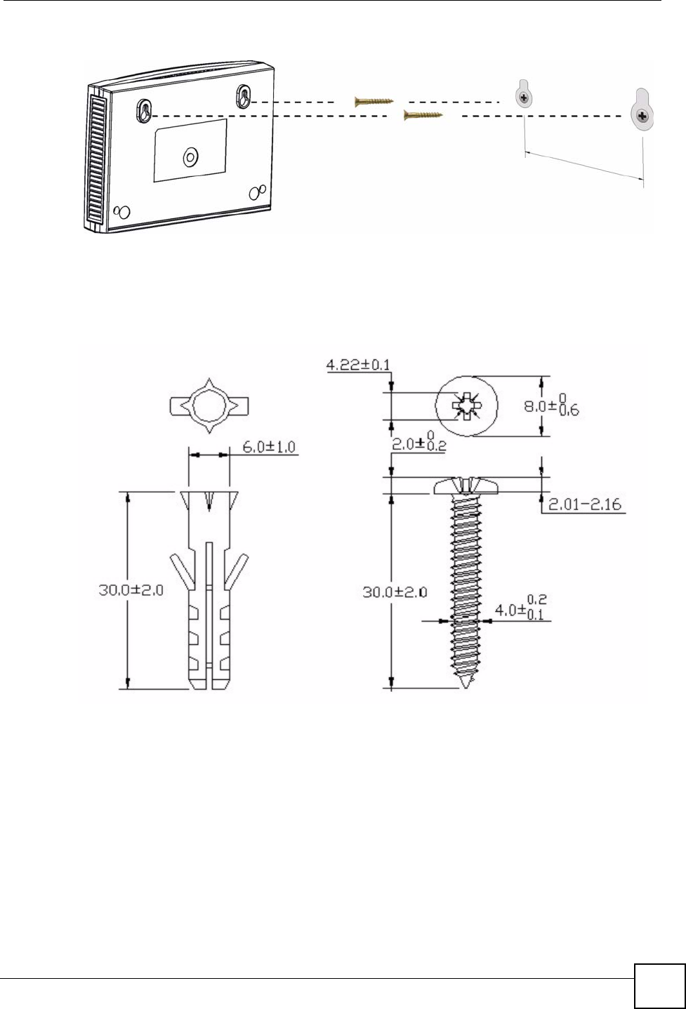
Appendix A Product Specifications and Wall-Mounting Instructions
NBG318S User’s Guide 227
Figure 128 Wall-mounting Example
The following are dimensions of an M4 tap screw and masonry plug used for wall mounting.
All measurements are in millimeters (mm).
Figure 129 Masonry Plug and M4 Tap Screw

Appendix A Product Specifications and Wall-Mounting Instructions
NBG318S User’s Guide
228
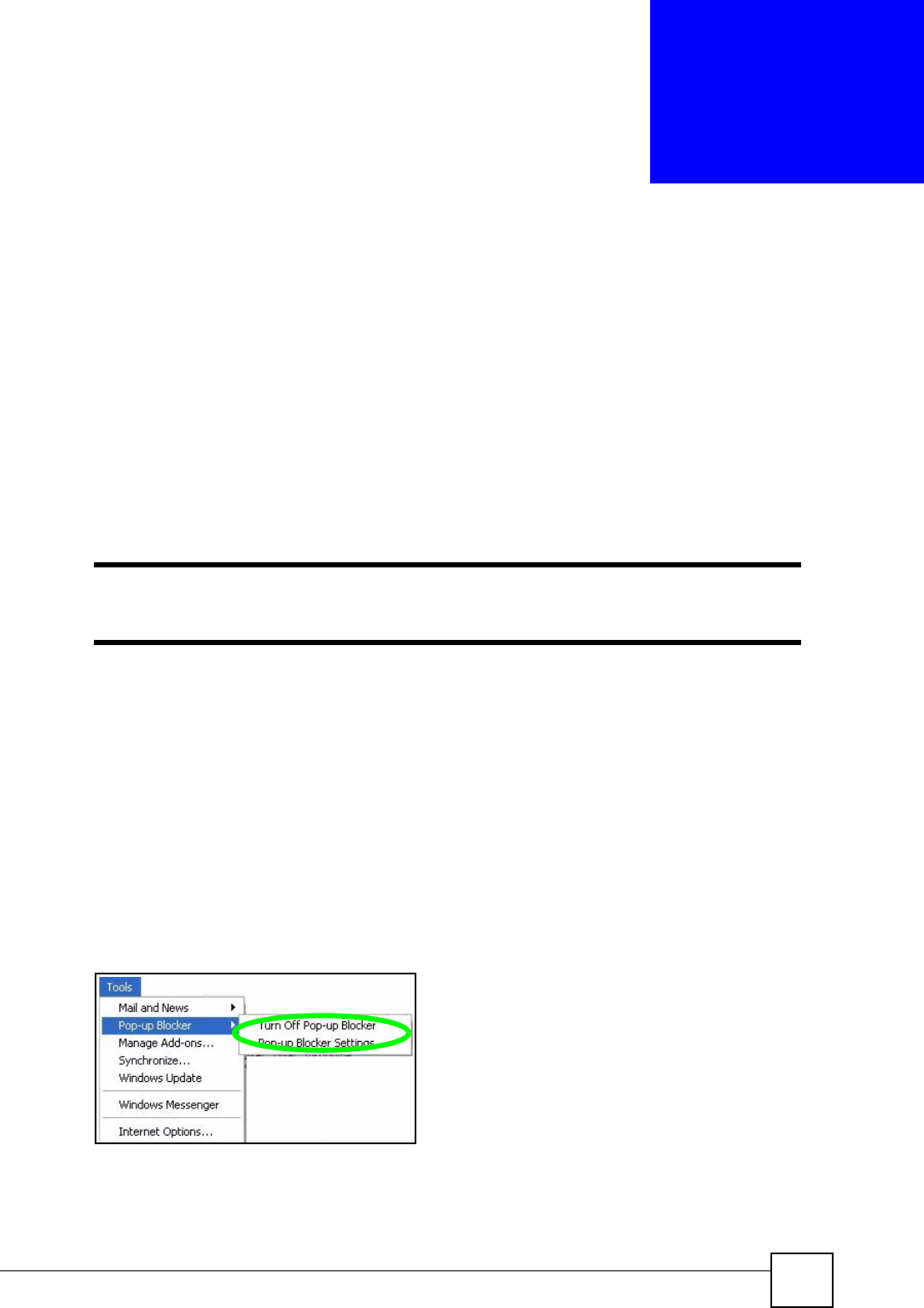
NBG318S User’s Guide 229
APPENDIX B
Pop-up Windows, JavaScripts
and Java Permissions
In order to use the web configurator you need to allow:
• Web browser pop-up windows from your device.
• JavaScripts (enabled by default).
• Java permissions (enabled by default).
"Internet Explorer 6 screens are used here. Screens for other Internet Explorer
versions may vary.
Internet Explorer Pop-up Blockers
You may have to disable pop-up blocking to log into your device.
Either disable pop-up blocking (enabled by default in Windows XP SP (Service Pack) 2) or
allow pop-up blocking and create an exception for your device’s IP address.
Disable pop-up Blockers
1In Internet Explorer, select Tools, Pop-up Blocker and then select Turn Off Pop-up
Blocker.
Figure 130 Pop-up Blocker
You can also check if pop-up blocking is disabled in the Pop-up Blocker section in the
Privacy tab.
1In Internet Explorer, select Tools, Internet Options, Privacy.
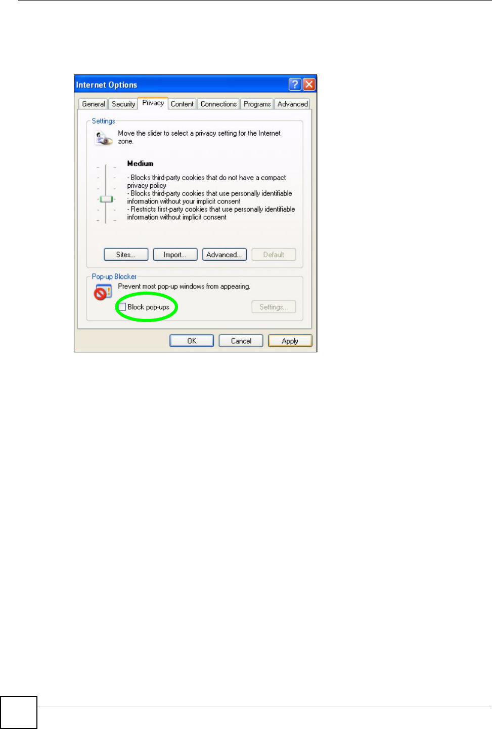
Appendix B Pop-up Windows, JavaScripts and Java Permissions
NBG318S User’s Guide
230
2Clear the Block pop-ups check box in the Pop-up Blocker section of the screen. This
disables any web pop-up blockers you may have enabled.
Figure 131 Internet Options: Privacy
3Click Apply to save this setting.
Enable pop-up Blockers with Exceptions
Alternatively, if you only want to allow pop-up windows from your device, see the following
steps.
1In Internet Explorer, select Tools, Internet Options and then the Privacy tab.
2Select Settings…to open the Pop-up Blocker Settings screen.