ZyXEL Communications NBG318S Wireless Ethernet Adapter User Manual NBG 318 User s Guide
ZyXEL Communications Corporation Wireless Ethernet Adapter NBG 318 User s Guide
Contents
- 1. User Manual 1
- 2. Users Manual 2
- 3. Users Manual 3
- 4. Users Manual 4
Users Manual 3


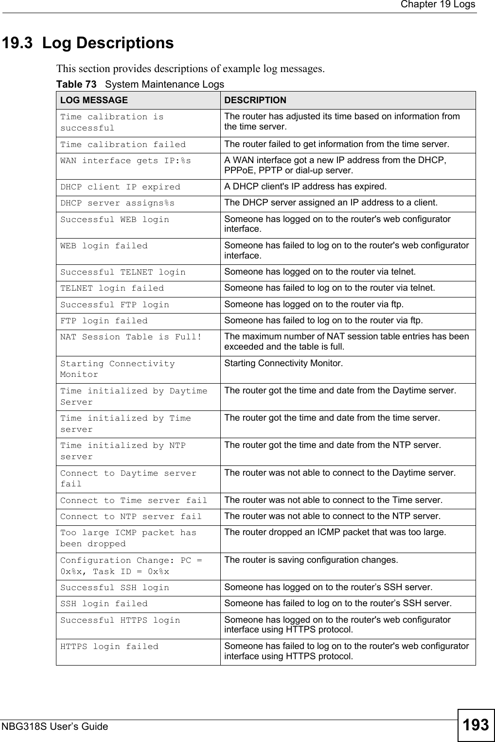
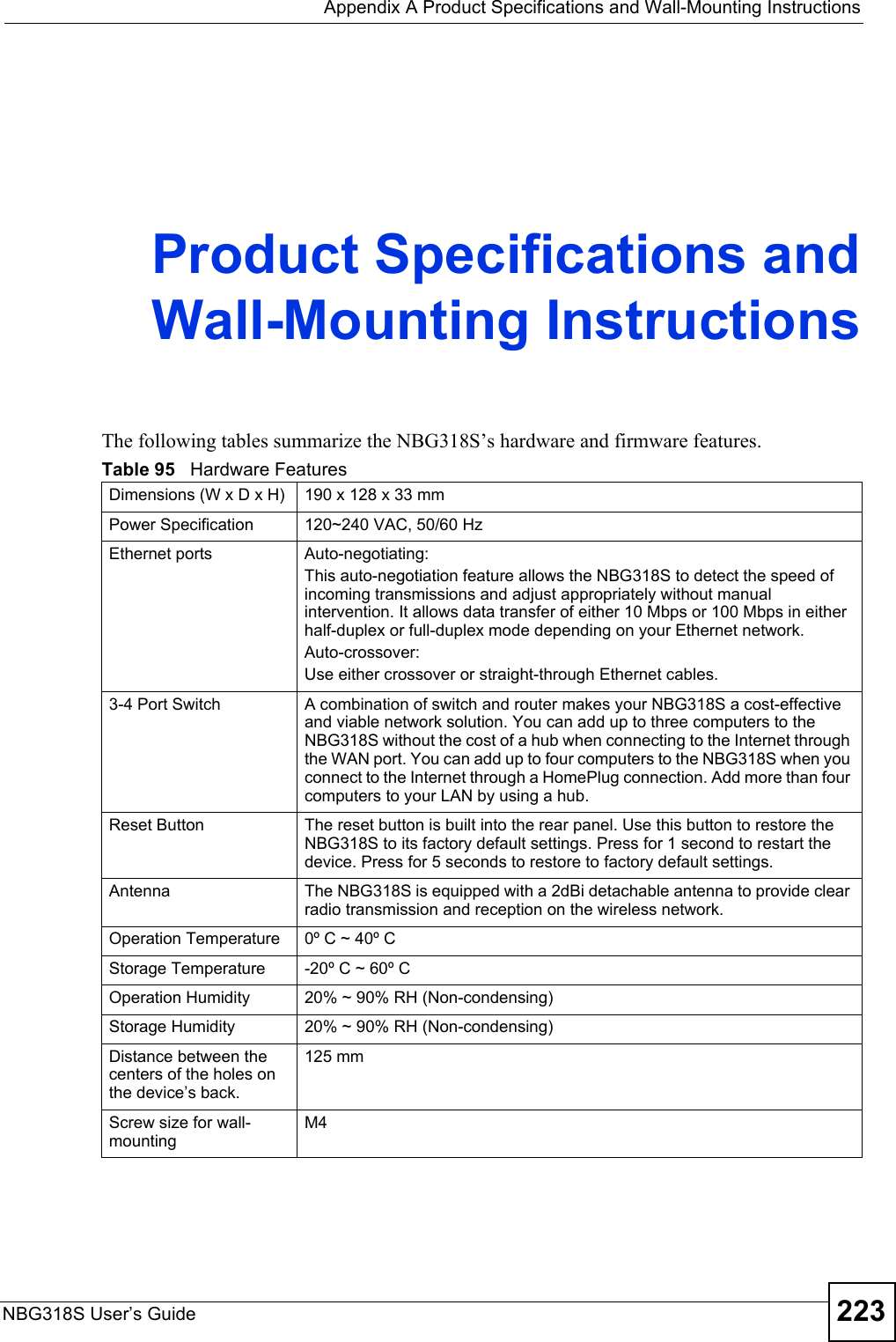
![Chapter 19 LogsNBG318S User’s Guide194 Table 74 System Error LogsLOG MESSAGE DESCRIPTION%s exceeds the max. number of session per host!This attempt to create a NAT session exceeds the maximum number of NAT session table entries allowed to be created per host.setNetBIOSFilter: calloc errorThe router failed to allocate memory for the NetBIOS filter settings.readNetBIOSFilter: calloc errorThe router failed to allocate memory for the NetBIOS filter settings.WAN connection is down. A WAN connection is down. You cannot access the network through this interface.Table 75 Access Control LogsLOG MESSAGE DESCRIPTIONFirewall default policy: [TCP | UDP | IGMP | ESP | GRE | OSPF] <Packet Direction>Attempted TCP/UDP/IGMP/ESP/GRE/OSPF access matched the default policy and was blocked or forwarded according to the default policy’s setting.Firewall rule [NOT] match:[TCP | UDP | IGMP | ESP | GRE | OSPF] <Packet Direction>, <rule:%d>Attempted TCP/UDP/IGMP/ESP/GRE/OSPF access matched (or did not match) a configured firewall rule (denoted by its number) and was blocked or forwarded according to the rule. Triangle route packet forwarded: [TCP | UDP | IGMP | ESP | GRE | OSPF]The firewall allowed a triangle route session to pass through.Packet without a NAT table entry blocked: [TCP | UDP | IGMP | ESP | GRE | OSPF]The router blocked a packet that didn't have a corresponding NAT table entry.Router sent blocked web site message: TCPThe router sent a message to notify a user that the router blocked access to a web site that the user requested.Table 76 TCP Reset LogsLOG MESSAGE DESCRIPTIONUnder SYN flood attack, sent TCP RSTThe router sent a TCP reset packet when a host was under a SYN flood attack (the TCP incomplete count is per destination host.) Exceed TCP MAX incomplete, sent TCP RSTThe router sent a TCP reset packet when the number of TCP incomplete connections exceeded the user configured threshold. (the TCP incomplete count is per destination host.) Note: Refer to TCP Maximum Incomplete in the Firewall Attack Alerts screen. Peer TCP state out of order, sent TCP RSTThe router sent a TCP reset packet when a TCP connection state was out of order.Note: The firewall refers to RFC793 Figure 6 to check the TCP state.](https://usermanual.wiki/ZyXEL-Communications/NBG318S.Users-Manual-3/User-Guide-812923-Page-34.png)
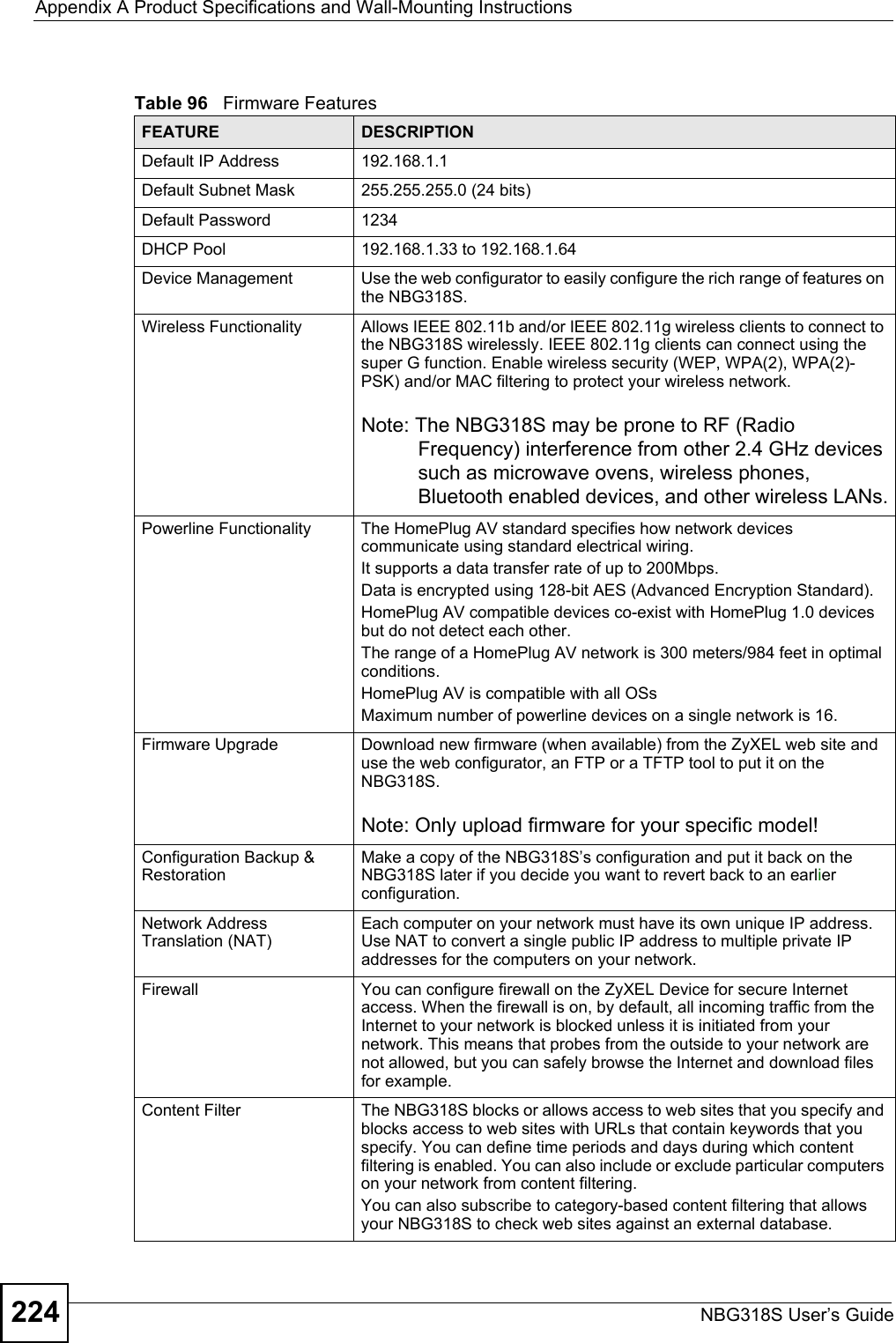
![Chapter 19 LogsNBG318S User’s Guide 195 Firewall session time out, sent TCP RSTThe router sent a TCP reset packet when a dynamic firewall session timed out.The default timeout values are as follows:ICMP idle timeout: 3 minutesUDP idle timeout: 3 minutesTCP connection (three way handshaking) timeout: 270 secondsTCP FIN-wait timeout: 2 MSL (Maximum Segment Lifetime set in the TCP header).TCP idle (established) timeout (s): 150 minutesTCP reset timeout: 10 secondsExceed MAX incomplete, sent TCP RSTThe router sent a TCP reset packet when the number of incomplete connections (TCP and UDP) exceeded the user-configured threshold. (Incomplete count is for all TCP and UDP connections through the firewall.)Note: When the number of incomplete connections (TCP + UDP) > “Maximum Incomplete High”, the router sends TCP RST packets for TCP connections and destroys TOS (firewall dynamic sessions) until incomplete connections < “Maximum Incomplete Low”.Access block, sent TCP RSTThe router sends a TCP RST packet and generates this log if you turn on the firewall TCP reset mechanism (via CI command: "sys firewall tcprst").Table 77 Packet Filter LogsLOG MESSAGE DESCRIPTION[TCP | UDP | ICMP | IGMP | Generic] packet filter matched (set:%d, rule:%d)Attempted access matched a configured filter rule (denoted by its set and rule number) and was blocked or forwarded according to the rule.Table 78 ICMP LogsLOG MESSAGE DESCRIPTIONFirewall default policy: ICMP <Packet Direction>, <type:%d>, <code:%d>ICMP access matched the default policy and was blocked or forwarded according to the user's setting. For type and code details, see Table 87 on page 200.Firewall rule [NOT] match: ICMP <Packet Direction>, <rule:%d>, <type:%d>, <code:%d>ICMP access matched (or didn’t match) a firewall rule (denoted by its number) and was blocked or forwarded according to the rule. For type and code details, see Table 87 on page 200.Triangle route packet forwarded: ICMPThe firewall allowed a triangle route session to pass through.Packet without a NAT table entry blocked: ICMPThe router blocked a packet that didn’t have a corresponding NAT table entry.Unsupported/out-of-order ICMP: ICMPThe firewall does not support this kind of ICMP packets or the ICMP packets are out of order.Router reply ICMP packet: ICMP The router sent an ICMP reply packet to the sender.Table 76 TCP Reset Logs (continued)LOG MESSAGE DESCRIPTION](https://usermanual.wiki/ZyXEL-Communications/NBG318S.Users-Manual-3/User-Guide-812923-Page-35.png)
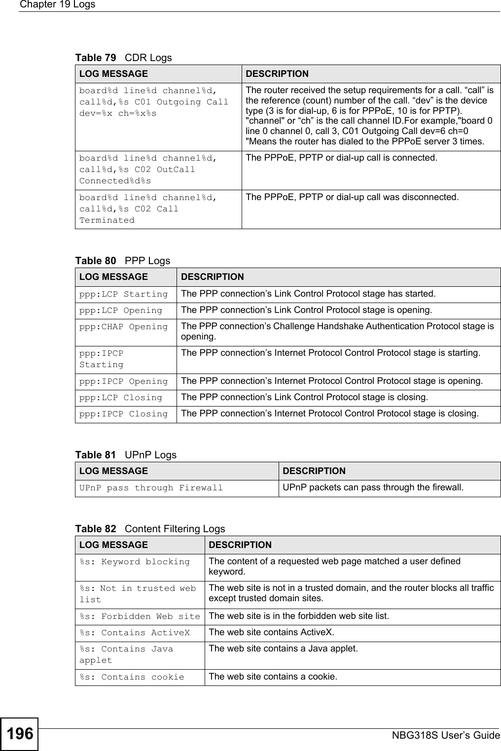
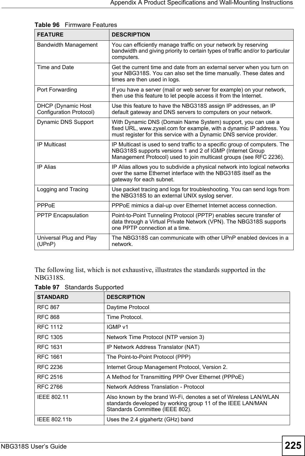
![Chapter 19 LogsNBG318S User’s Guide 197 %s: Proxy mode detectedThe router detected proxy mode in the packet.%s The content filter server responded that the web site is in the blocked category list, but it did not return the category type.%s:%s The content filter server responded that the web site is in the blocked category list, and returned the category type.%s(cache hit) The system detected that the web site is in the blocked list from the local cache, but does not know the category type.%s:%s(cache hit) The system detected that the web site is in blocked list from the local cache, and knows the category type.%s: Trusted Web site The web site is in a trusted domain.%s When the content filter is not on according to the time schedule or you didn't select the "Block Matched Web Site” check box, the system forwards the web content.Waiting content filter server timeoutThe external content filtering server did not respond within the timeout period.DNS resolving failed The NBG318S cannot get the IP address of the external content filtering via DNS query.Creating socket failed The NBG318S cannot issue a query because TCP/IP socket creation failed, port:port number.Connecting to content filter server failThe connection to the external content filtering server failed.License key is invalid The external content filtering license key is invalid.Table 83 Attack LogsLOG MESSAGE DESCRIPTIONattack [TCP | UDP | IGMP | ESP | GRE | OSPF]The firewall detected a TCP/UDP/IGMP/ESP/GRE/OSPF attack.attack ICMP (type:%d, code:%d)The firewall detected an ICMP attack. For type and code details, see Table 87 on page 200.land [TCP | UDP | IGMP | ESP | GRE | OSPF]The firewall detected a TCP/UDP/IGMP/ESP/GRE/OSPF land attack.land ICMP (type:%d, code:%d)The firewall detected an ICMP land attack. For type and code details, see Table 87 on page 200.ip spoofing - WAN [TCP | UDP | IGMP | ESP | GRE | OSPF]The firewall detected an IP spoofing attack on the WAN port.ip spoofing - WAN ICMP (type:%d, code:%d)The firewall detected an ICMP IP spoofing attack on the WAN port. For type and code details, see Table 87 on page 200.icmp echo: ICMP (type:%d, code:%d)The firewall detected an ICMP echo attack. For type and code details, see Table 87 on page 200.syn flood TCP The firewall detected a TCP syn flood attack.ports scan TCP The firewall detected a TCP port scan attack.teardrop TCP The firewall detected a TCP teardrop attack.Table 82 Content Filtering Logs (continued)LOG MESSAGE DESCRIPTION](https://usermanual.wiki/ZyXEL-Communications/NBG318S.Users-Manual-3/User-Guide-812923-Page-37.png)
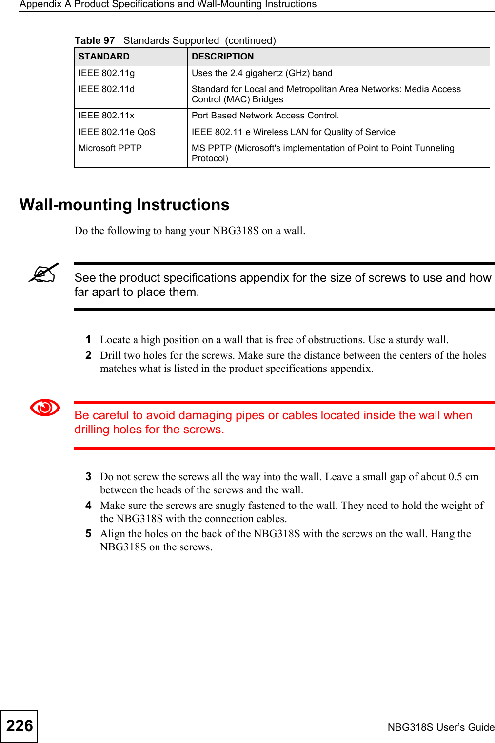
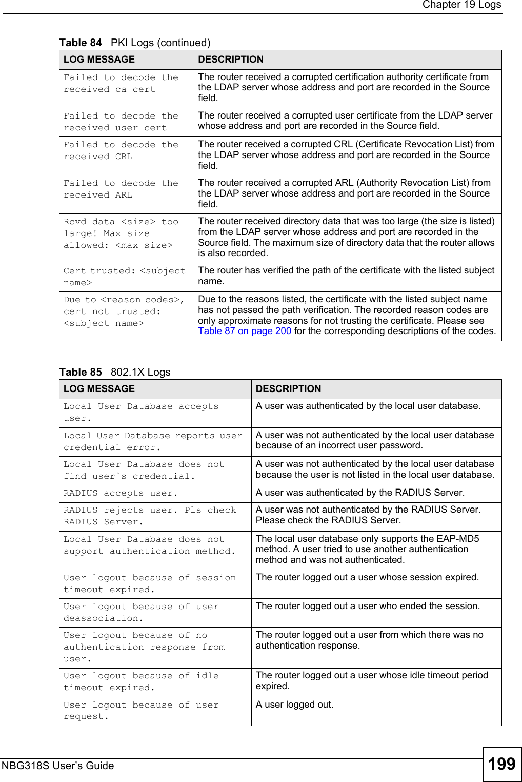
![Chapter 19 LogsNBG318S User’s Guide198 teardrop UDP The firewall detected an UDP teardrop attack.teardrop ICMP (type:%d, code:%d)The firewall detected an ICMP teardrop attack. For type and code details, see Table 87 on page 200.illegal command TCP The firewall detected a TCP illegal command attack.NetBIOS TCP The firewall detected a TCP NetBIOS attack.ip spoofing - no routing entry [TCP | UDP | IGMP | ESP | GRE | OSPF]The firewall classified a packet with no source routing entry as an IP spoofing attack.ip spoofing - no routing entry ICMP (type:%d, code:%d)The firewall classified an ICMP packet with no source routing entry as an IP spoofing attack.vulnerability ICMP (type:%d, code:%d)The firewall detected an ICMP vulnerability attack. For type and code details, see Table 87 on page 200.traceroute ICMP (type:%d, code:%d)The firewall detected an ICMP traceroute attack. For type and code details, see Table 87 on page 200.Table 84 PKI LogsLOG MESSAGE DESCRIPTIONEnrollment successful The SCEP online certificate enrollment was successful. The Destination field records the certification authority server IP address and port.Enrollment failed The SCEP online certificate enrollment failed. The Destination field records the certification authority server’s IP address and port.Failed to resolve <SCEP CA server url>The SCEP online certificate enrollment failed because the certification authority server’s address cannot be resolved.Enrollment successful The CMP online certificate enrollment was successful. The Destination field records the certification authority server’s IP address and port.Enrollment failed The CMP online certificate enrollment failed. The Destination field records the certification authority server’s IP address and port.Failed to resolve <CMP CA server url>The CMP online certificate enrollment failed because the certification authority server’s IP address cannot be resolved.Rcvd ca cert: <subject name>The router received a certification authority certificate, with subject name as recorded, from the LDAP server whose IP address and port are recorded in the Source field.Rcvd user cert: <subject name>The router received a user certificate, with subject name as recorded, from the LDAP server whose IP address and port are recorded in the Source field.Rcvd CRL <size>: <issuer name>The router received a CRL (Certificate Revocation List), with size and issuer name as recorded, from the LDAP server whose IP address and port are recorded in the Source field.Rcvd ARL <size>: <issuer name>The router received an ARL (Authority Revocation List), with size and issuer name as recorded, from the LDAP server whose address and port are recorded in the Source field.Table 83 Attack Logs (continued)LOG MESSAGE DESCRIPTION](https://usermanual.wiki/ZyXEL-Communications/NBG318S.Users-Manual-3/User-Guide-812923-Page-38.png)
![Chapter 23 TroubleshootingNBG318S User’s Guide 2156If the problem continues, contact the network administrator or vendor, or try one of the advanced suggestions.Advanced Suggestions• Try to access the NBG318S using another service, such as Telnet. If you can access the NBG318S, check the remote management settings and firewall rules to find out why the NBG318S does not respond to HTTP.• If your computer is connected to the WAN port or is connected wirelessly, use a computer that is connected to a LAN/ETHERNET port.VI can see the Login screen, but I cannot log in to the NBG318S.1Make sure you have entered the password correctly. The default password is 1234. This field is case-sensitive, so make sure [Caps Lock] is not on. 2You cannot log in to the web configurator while someone is using Telnet to access the NBG318S. Log out of the NBG318S in the other session, or ask the person who is logged in to log out. 3Disconnect and re-connect the power adaptor or cord to the NBG318S. 4If this does not work, you have to reset the device to its factory defaults. See Section 23.4 on page 217.VI cannot Telnet to the NBG318S. See the troubleshooting suggestions for I cannot see or access the Login screen in the web configurator. Ignore the suggestions about your browser.VI cannot use FTP to upload / download the configuration file. / I cannot use FTP to upload new firmware. See the troubleshooting suggestions for I cannot see or access the Login screen in the web configurator. Ignore the suggestions about your browser.23.3 Internet AccessVI cannot access the Internet.](https://usermanual.wiki/ZyXEL-Communications/NBG318S.Users-Manual-3/User-Guide-812923-Page-55.png)
![Chapter 23 TroubleshootingNBG318S User’s Guide2161Check the hardware connections, and make sure the LEDs are behaving as expected. See the Quick Start Guide.2Make sure you entered your ISP account information correctly in the wizard. These fields are case-sensitive, so make sure [Caps Lock] is not on.3If you are trying to access the Internet wirelessly, make sure the wireless settings in the wireless client are the same as the settings in the AP. 4Disconnect all the cables from your device, and follow the directions in the Quick Start Guide again. 5Go to Maintenance > Sys OP Mode > General. Check your System Operation Mode setting. • Select Router (Ethernet WAN) if your network is configured to access the Internet through an Ethernet connection to a DSL or cable modem.• Select Router (HomePlug WAN) if your network is configured to access the Internet through a HomePlug connection.6If the problem continues, contact your ISP.VI cannot access the Internet anymore. I had access to the Internet (with the NBG318S), but my Internet connection is not available anymore.1Check the hardware connections, and make sure the LEDs are behaving as expected. See the Quick Start Guide and Section 1.4 on page 33. 2Reboot the NBG318S.3If the problem continues, contact your ISP. VThe Internet connection is slow or intermittent.1There might be a lot of traffic on the network. Look at the LEDs, and check Section 1.4 on page 33. If the NBG318S is sending or receiving a lot of information, try closing some programs that use the Internet, especially peer-to-peer applications. 2Check the signal strength. If the signal strength is low, try moving the NBG318S closer to the AP if possible, and look around to see if there are any devices that might be interfering with the wireless network (for example, microwaves, other wireless networks, and so on).3Reboot the NBG318S.4If the problem continues, contact the network administrator or vendor, or try one of the advanced suggestions.Advanced Suggestions• Check the settings for bandwidth management. If it is disabled, you might consider activating it. If it is enabled, you might consider changing the allocations. • Check the settings for QoS. If it is disabled, you might consider activating it. If it is enabled, you might consider raising or lowering the priority for some applications.](https://usermanual.wiki/ZyXEL-Communications/NBG318S.Users-Manual-3/User-Guide-812923-Page-56.png)