ZyXEL Communications NBG334W Wireless Firewall Router User Manual NBG334W User s Guide
ZyXEL Communications Corporation Wireless Firewall Router NBG334W User s Guide
Contents
- 1. Users Manual Part 1
- 2. Users Manual Part 2
- 3. Users Manual Part 3
- 4. Users Manual Part 4
Users Manual Part 2
Chapter 3 Connection Wizard
NBG334W User’s Guide
50
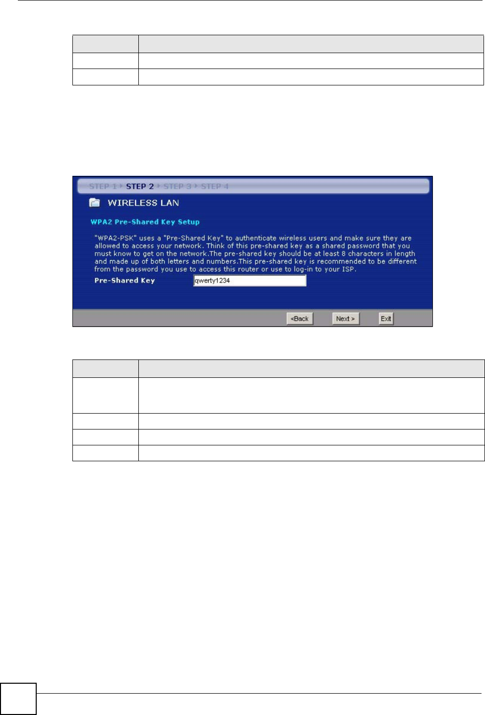
3.3.2 Extend (WPA-PSK or WPA2-PSK) Security
Choose Extend (WPA-PSK) or Extend (WPA2-PSK) security in the Wireless LAN setup
screen to set up a Pre-Shared Key.
Figure 17 Wizard Step 2: Extend (WPA-PSK or WPA2-PSK) Security
The following table describes the labels in this screen.
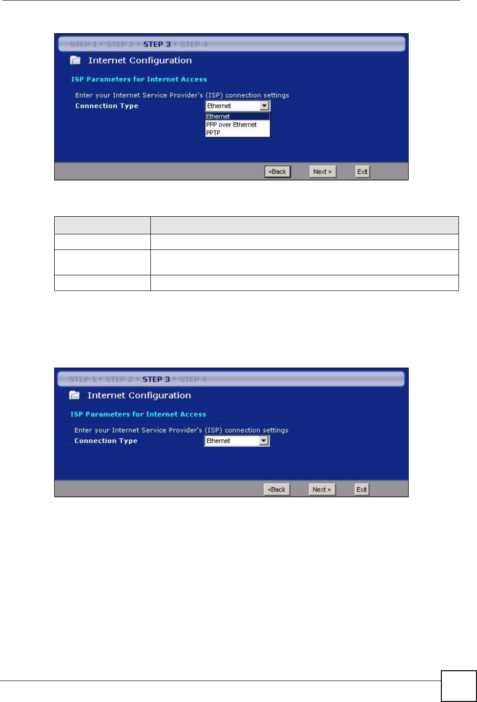
3.4 Connection Wizard: STEP 3: Internet Configuration
The NBG334W offers three Internet connection types. They are Ethernet, PPP over
Ethernet or PPTP. The wizard attempts to detect which WAN connection type you are using.
If the wizard does not detect a connection type, you must select one from the drop-down list
box. Check with your ISP to make sure you use the correct type.
This wizard screen varies according to the connection type that you select.
Next Click Next to proceed to the next screen.
Exit Click Exit to close the wizard screen without saving.
Table 11 Wizard Step 2: Basic (WEP) Security
LABEL DESCRIPTION
Table 12 Wizard Step 2: Extend (WPA-PSK or WPA2-PSK) Security
LABEL DESCRIPTION
Pre-Shared
Key
Type from 8 to 63 case-sensitive ASCII characters. You can set up the most secure
wireless connection by configuring WPA in the wireless LAN screens. You need to
configure an authentication server to do this.
Back Click Back to display the previous screen.
Next Click Next to proceed to the next screen.
Exit Click Exit to close the wizard screen without saving.
Chapter 3 Connection Wizard
NBG334W User’s Guide 51
Figure 18 Wizard Step 3: ISP Parameters.
The following table describes the labels in this screen,
3.4.1 Ethernet Connection
Choose Ethernet when the WAN port is used as a regular Ethernet.
Figure 19 Wizard Step 3: Ethernet Connection
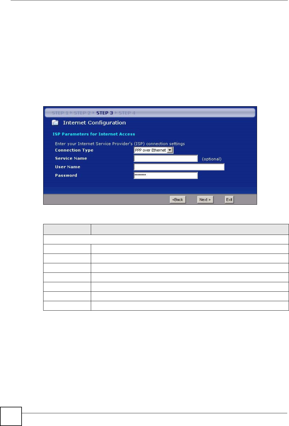
3.4.2 PPPoE Connection
Point-to-Point Protocol over Ethernet (PPPoE) functions as a dial-up connection. PPPoE is an
IETF (Internet Engineering Task Force) standard specifying how a host personal computer
interacts with a broadband modem (for example DSL, cable, wireless, etc.) to achieve access
to high-speed data networks.
For the service provider, PPPoE offers an access and authentication method that works with
existing access control systems (for instance, RADIUS).
Table 13 Wizard Step 3: ISP Parameters
CONNECTION TYPE DESCRIPTION
Ethernet Select the Ethernet option when the WAN port is used as a regular Ethernet.
PPPoE Select the PPP over Ethernet option for a dial-up connection. If your ISP
gave you a an IP address and/or subnet mask, then select PPTP.
PPTP Select the PPTP option for a dial-up connection.
Chapter 3 Connection Wizard
NBG334W User’s Guide
52
One of the benefits of PPPoE is the ability to let end users access one of multiple network
services, a function known as dynamic service selection. This enables the service provider to
easily create and offer new IP services for specific users.
Operationally, PPPoE saves significant effort for both the subscriber and the ISP/carrier, as it
requires no specific configuration of the broadband modem at the subscriber’s site.
By implementing PPPoE directly on the NBG334W (rather than individual computers), the
computers on the LAN do not need PPPoE software installed, since the NBG334W does that
part of the task. Furthermore, with NAT, all of the LAN's computers will have Internet access.
Refer to the appendix for more information on PPPoE.
Figure 20 Wizard Step 3: PPPoE Connection
The following table describes the labels in this screen.
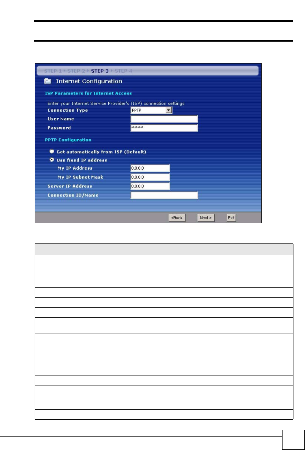
3.4.3 PPTP Connection
Point-to-Point Tunneling Protocol (PPTP) is a network protocol that enables transfers of data
from a remote client to a private server, creating a Virtual Private Network (VPN) using TCP/
IP-based networks.
PPTP supports on-demand, multi-protocol, and virtual private networking over public
networks, such as the Internet.
Refer to the appendix for more information on PPTP.
Table 14 Wizard Step 3: PPPoE Connection
LABEL DESCRIPTION
ISP Parameter for Internet Access
Connection Type Select the PPP over Ethernet option for a dial-up connection.
Service Name Type the name of your service provider.
User Name Type the user name given to you by your ISP.
Password Type the password associated with the user name above.
Back Click Back to return to the previous screen.
Next Click Next to continue.
Exit Click Exit to close the wizard screen without saving.
Chapter 3 Connection Wizard
NBG334W User’s Guide 53
"The NBG334W supports one PPTP server connection at any given time.
Figure 21 Wizard Step 3: PPTP Connection
The following table describes the fields in this screen
Table 15 Wizard Step 3: PPTP Connection
LABEL DESCRIPTION
ISP Parameters for Internet Access
Connection Type Select PPTP from the drop-down list box. To configure a PPTP client, you must
configure the User Name and Password fields for a PPP connection and the
PPTP parameters for a PPTP connection.
User Name Type the user name given to you by your ISP.
Password Type the password associated with the User Name above.
PPTP Configuration
Get automatically
from ISP
Select this radio button if your ISP did not assign you a fixed IP address.
Use fixed IP
address
Select this radio button, provided by your ISP to give the NBG334W a fixed,
unique IP address.
My IP Address Type the (static) IP address assigned to you by your ISP.
My IP Subnet
Mask
Type the subnet mask assigned to you by your ISP (if given).
Server IP Address Type the IP address of the PPTP server.
Connection ID/
Name
Enter the connection ID or connection name in this field. It must follow the "c:id"
and "n:name" format. For example, C:12 or N:My ISP.
This field is optional and depends on the requirements of your ISP.
Back Click Back to return to the previous screen.
Chapter 3 Connection Wizard
NBG334W User’s Guide
54
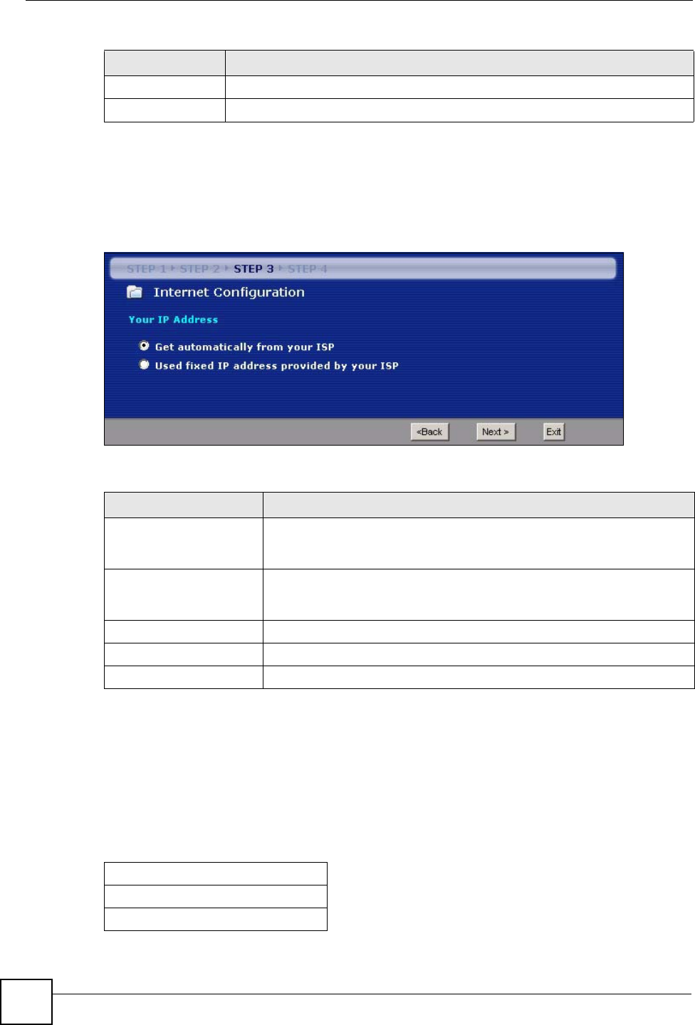
3.4.4 Your IP Address
The following wizard screen allows you to assign a fixed IP address or give the NBG334W an
automatically assigned IP address depending on your ISP.
Figure 22 Wizard Step 3: Your IP Address
The following table describes the labels in this screen
3.4.5 WAN IP Address Assignment
Every computer on the Internet must have a unique IP address. If your networks are isolated
from the Internet, for instance, only between your two branch offices, you can assign any IP
addresses to the hosts without problems. However, the Internet Assigned Numbers Authority
(IANA) has reserved the following three blocks of IP addresses specifically for private
networks.
Next Click Next to continue.
Exit Click Exit to close the wizard screen without saving.
Table 15 Wizard Step 3: PPTP Connection
LABEL DESCRIPTION
Table 16 Wizard Step 3: Your IP Address
LABEL DESCRIPTION
Get automatically from
your ISP
Select this option If your ISP did not assign you a fixed IP address. This is
the default selection. If you choose this option, skip directly to section
3.4.9.
Use fixed IP address
provided by your ISP
Select this option if you were given IP address and/or DNS server settings
by the ISP. The fixed IP address should be in the same subnet as your
broadband modem or router.
Back Click Back to return to the previous screen.
Next Click Next to continue.
Exit Click Exit to close the wizard screen without saving.
Table 17 Private IP Address Ranges
10.0.0.0 -10.255.255.255
172.16.0.0 -172.31.255.255
192.168.0.0 -192.168.255.255

Chapter 3 Connection Wizard
NBG334W User’s Guide 55
You can obtain your IP address from the IANA, from an ISP or have it assigned by a private
network. If you belong to a small organization and your Internet access is through an ISP, the
ISP can provide you with the Internet addresses for your local networks. On the other hand, if
you are part of a much larger organization, you should consult your network administrator for
the appropriate IP addresses.
"Regardless of your particular situation, do not create an arbitrary IP address;
always follow the guidelines above. For more information on address
assignment, please refer to RFC 1597, Address Allocation for Private Internets
and RFC 1466, Guidelines for Management of IP Address Space.
3.4.6 IP Address and Subnet Mask
Similar to the way houses on a street share a common street name, so too do computers on a
LAN share one common network number.
Where you obtain your network number depends on your particular situation. If the ISP or
your network administrator assigns you a block of registered IP addresses, follow their
instructions in selecting the IP addresses and the subnet mask.
If the ISP did not explicitly give you an IP network number, then most likely you have a single
user account and the ISP will assign you a dynamic IP address when the connection is
established. The Internet Assigned Number Authority (IANA) reserved this block of addresses
specifically for private use; please do not use any other number unless you are told otherwise.
Let's say you select 192.168.1.0 as the network number; which covers 254 individual
addresses, from 192.168.1.1 to 192.168.1.254 (zero and 255 are reserved). In other words, the
first three numbers specify the network number while the last number identifies an individual
computer on that network.
Once you have decided on the network number, pick an IP address that is easy to remember,
for instance, 192.168.1.1, for your NBG334W, but make sure that no other device on your
network is using that IP address.
The subnet mask specifies the network number portion of an IP address. Your NBG334W will
compute the subnet mask automatically based on the IP address that you entered. You don't
need to change the subnet mask computed by the NBG334W unless you are instructed to do
otherwise.
3.4.7 DNS Server Address Assignment
Use DNS (Domain Name System) to map a domain name to its corresponding IP address and
vice versa, for instance, the IP address of www.zyxel.com is 204.217.0.2. The DNS server is
extremely important because without it, you must know the IP address of a computer before
you can access it.
The NBG334W can get the DNS server addresses in the following ways.
1The ISP tells you the DNS server addresses, usually in the form of an information sheet,
when you sign up. If your ISP gives you DNS server addresses, enter them in the DNS
Server fields in the Wizard and/or WAN > Internet Connection screen.
Chapter 3 Connection Wizard
NBG334W User’s Guide
56
2If the ISP did not give you DNS server information, leave the DNS Server fields set to
0.0.0.0 in the Wizard screen and/or set to From ISP in the WAN > Internet
Connection screen for the ISP to dynamically assign the DNS server IP addresses.
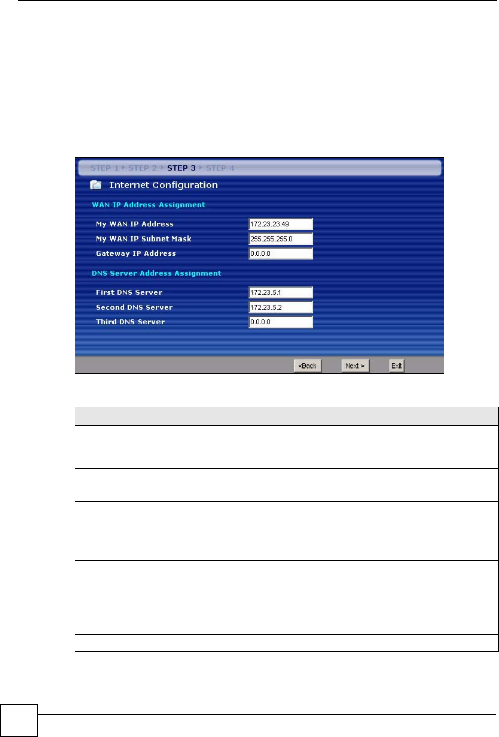
3.4.8 WAN IP and DNS Server Address Assignment
The following wizard screen allows you to assign a fixed WAN IP address and DNS server
addresses.
Figure 23 Wizard Step 3: WAN IP and DNS Server Addresses
The following table describes the labels in this screen
Table 18 Wizard Step 3: WAN IP and DNS Server Addresses
LABEL DESCRIPTION
WAN IP Address Assignment
My WAN IP Address Enter your WAN IP address in this field. The WAN IP address should be in
the same subnet as your DSL/Cable modem or router.
My WAN IP Subnet Mask Enter the IP subnet mask in this field.
Gateway IP Address Enter the gateway IP address in this field.
System DNS Server Address Assignment (if applicable)
DNS (Domain Name System) is for mapping a domain name to its corresponding IP address and vice
versa. The DNS server is extremely important because without it, you must know the IP address of a
computer before you can access it. The NBG334W uses a system DNS server (in the order you specify
here) to resolve domain names for DDNS and the time server.
First DNS Server
Second DNS Server
Third DNS Server
Enter the DNS server's IP address in the fields provided.
If you do not configure a system DNS server, you must use IP addresses
when configuring DDNS and the time server.
Back Click Back to return to the previous screen.
Next Click Next to continue.
Exit Click Exit to close the wizard screen without saving.
Chapter 3 Connection Wizard
NBG334W User’s Guide 57
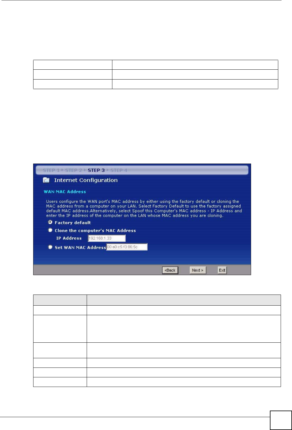
3.4.9 WAN MAC Address
Every Ethernet device has a unique MAC (Media Access Control) address. The MAC address
is assigned at the factory and consists of six pairs of hexadecimal characters, for example,
00:A0:C5:00:00:02.
This screen allows users to configure the WAN port's MAC address by either using the
NBG334W’s MAC address, copying the MAC address from a computer on your LAN or
manually entering a MAC address. Once it is successfully configured, the address will be
copied to the "rom" file (ZyNOS configuration file). It will not change unless you change the
setting or upload a different "rom" file. It is advisable to clone the MAC address from a
computer on your LAN even if your ISP does not presently require MAC address
authentication.
Figure 24 Wizard Step 3: WAN MAC Address
The following table describes the fields in this screen.
Table 19 Example of Network Properties for LAN Servers with Fixed IP Addresses
Choose an IP address 192.168.1.2-192.168.1.32; 192.168.1.65-192.168.1.254.
Subnet mask 255.255.255.0
Gateway (or default route) 192.168.1.1(NBG334W LAN IP)
Table 20 Wizard Step 3: WAN MAC Address
LABEL DESCRIPTION
Factory Default Select Factory Default to use the factory assigned default MAC address.
Clone the
computer’s MAC
address
Select this option and enter the IP address of the computer on the LAN whose
MAC you are cloning. It is advisable to clone the MAC address from a computer
on your LAN even if your ISP does not presently require MAC address
authentication.
Set WAN MAC
Address
Select this option and enter the MAC address you want to use.
Back Click Back to return to the previous screen.
Next Click Next to continue.
Exit Click Exit to close the wizard screen without saving.
Chapter 3 Connection Wizard
NBG334W User’s Guide
58
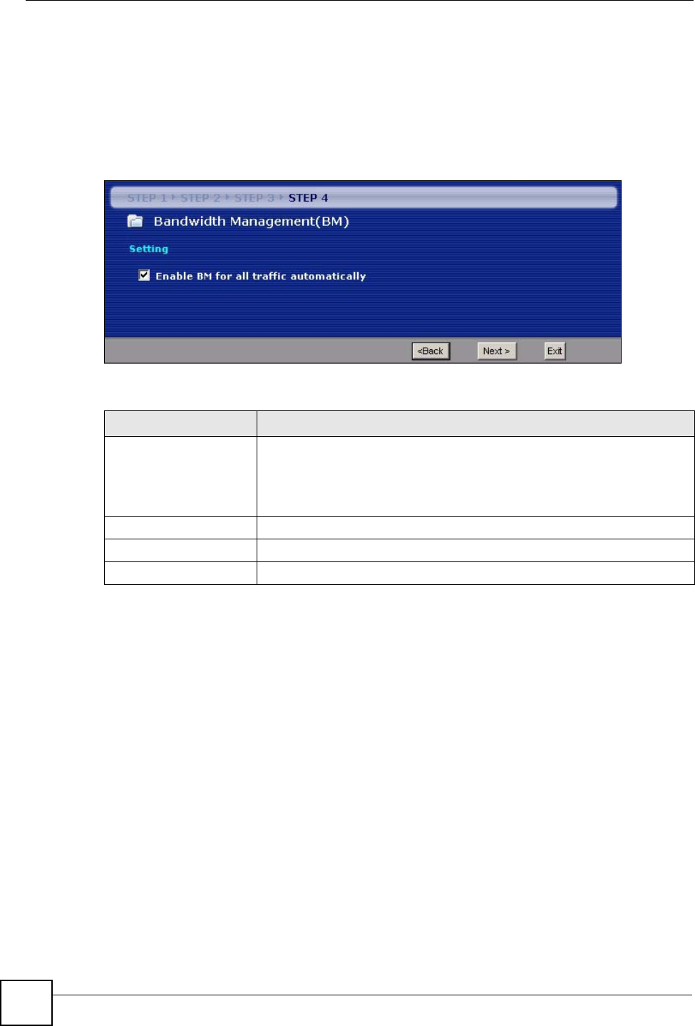
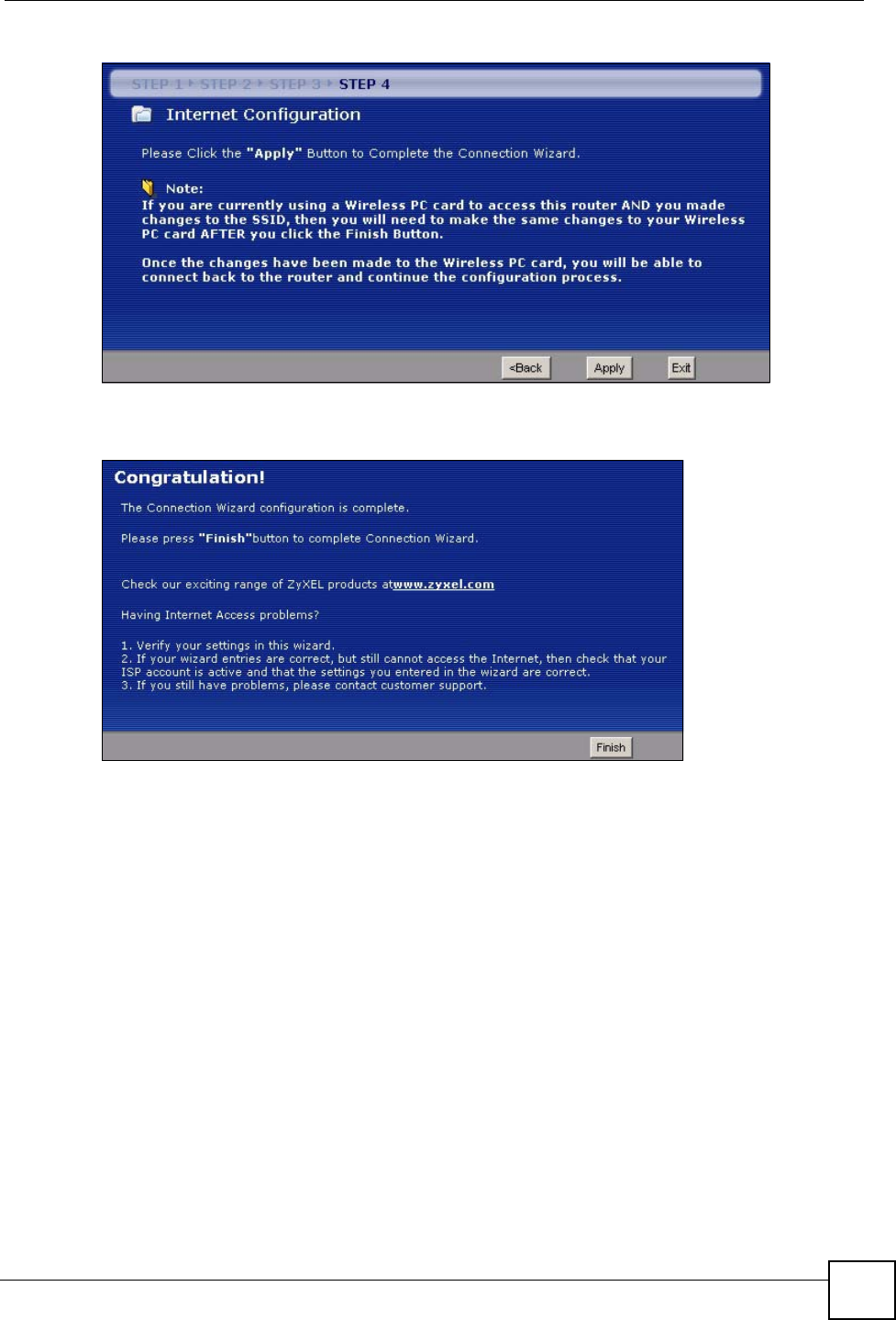
3.5 Connection Wizard: STEP 4: Bandwidth management
Bandwidth management allows you to control the amount of bandwidth going out through the
NBG334W’s WAN, LAN or WLAN port and prioritize the distribution of the bandwidth
according to the traffic type. This helps keep one service from using all of the available
bandwidth and shutting out other users.
Figure 25 Wizard Step 4: Bandwidth Management
The following fields describe the label in this screen.
3.6 Connection Wizard Complete
Click Apply to save your configuration.
Table 21 Wizard Step 4: Bandwidth Management
LABEL DESCRIPTION
Enable BM for all traffic
automatically
Select the check box to have the NBG334W apply bandwidth management
to traffic going out through the NBG334W’s WAN, LAN, HomePlug AV or
WLAN port. Bandwidth is allocated according to the traffic type
automatically. Real-time packets, such as VoIP traffic always get higher
priority.
Back Click Back to return to the previous screen.
Next Click Next to continue.
Exit Click Exit to close the wizard screen without saving.
Chapter 3 Connection Wizard
NBG334W User’s Guide 59
Figure 26 Connection Wizard Save
Follow the on-screen instructions and click Finish to complete the wizard setup.
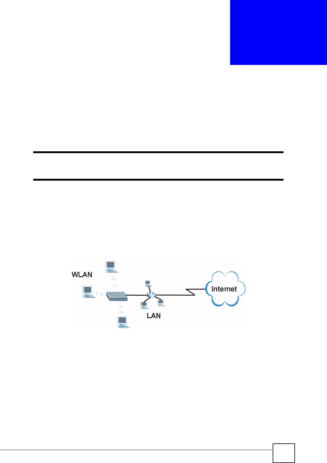
Figure 27 Connection Wizard Complete
Well done! You have successfully set up your NBG334W to operate on your network and
access the Internet.

Chapter 3 Connection Wizard
NBG334W User’s Guide
60
NBG334W User’s Guide 61
CHAPTER 4
AP Mode
This chapter discusses how to configure settings while your NBG334W is set to AP Mode.
Many screens that are available in Router Mode are not available in AP Mode.
"See Chapter 6 on page 89 for an example of setting up a wireless network in
AP mode.
4.1 AP Mode Overview
Use your NBG334W as an AP if you already have a router or gateway on your network. In this
mode your device bridges a wired network (LAN) and wireless LAN (WLAN) in the same
subnet. See the figure below for an example.
Figure 28 Wireless Internet Access in AP Mode
4.2 Setting your NBG334W to AP Mode
1Log into the web configurator if you haven’t already. See the Quick start Guide for
instructions on how to do this.
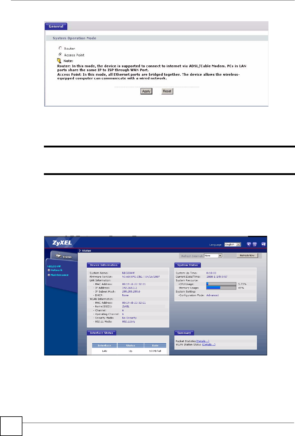
2To set your NBG334W to AP Mode, go to Maintenance > Sys OP Mode > General
and select Access Point.
Chapter 4 AP Mode
NBG334W User’s Guide
62
Figure 29 Maintenance > Sys OP Mode > General
3A pop-up appears providing information on this mode. Click OK in the pop-up message
window. (See Section 22.2 on page 200 for more information on the pop-up.) Click
Apply. Your NBG334W is now in AP Mode.
"You do not have to log in again or restart your device when you change
modes.
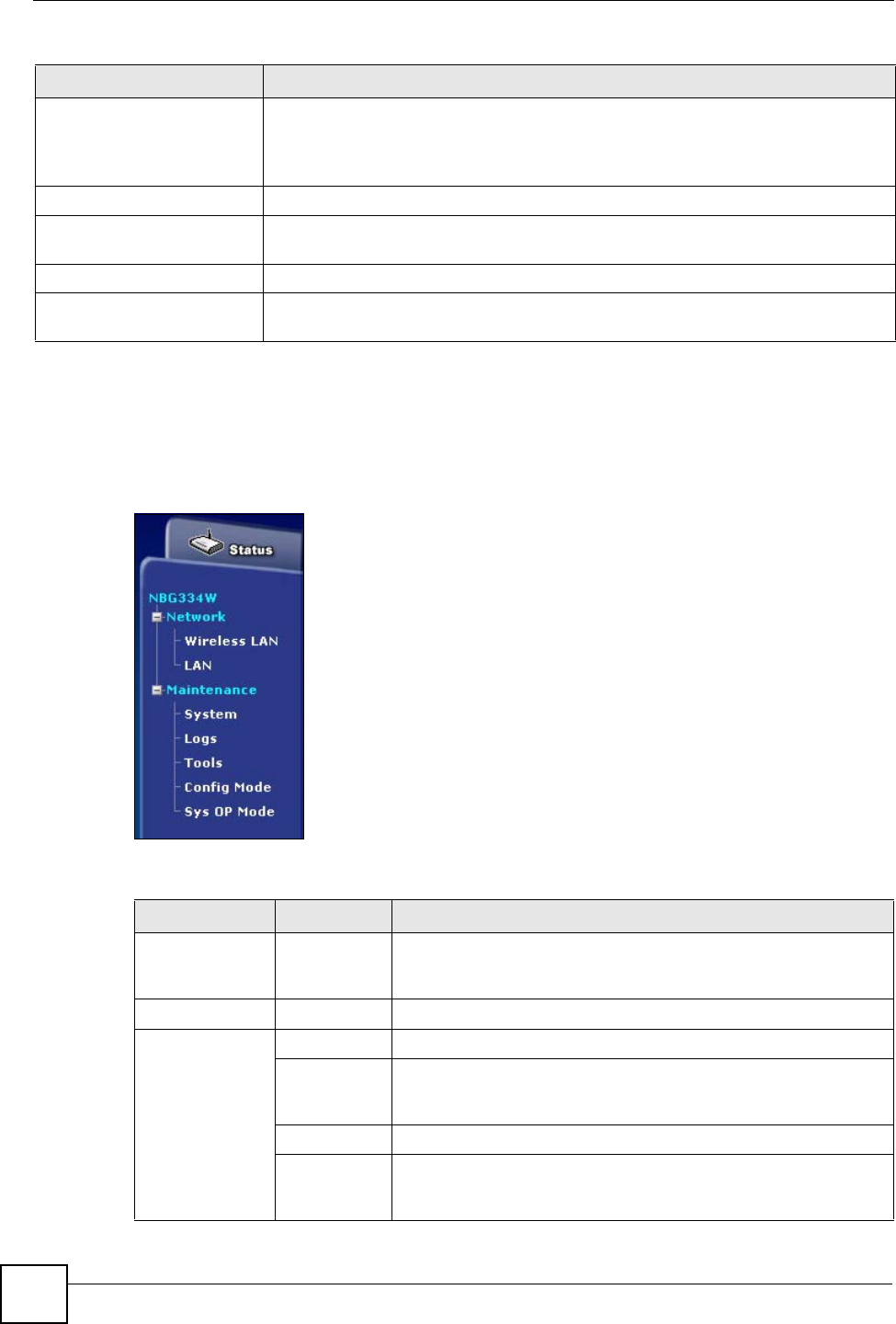
4.3 The Status Screen in AP Mode
Click on Status. The screen below shows the status screen in AP Mode.
Figure 30 Status: AP Mode

Chapter 4 AP Mode
NBG334W User’s Guide 63
The following table describes the labels shown in the Status screen.
Table 22 Web Configurator Status Screen
LABEL DESCRIPTION
Device Information
System Name This is the System Name you enter in the Maintenance > System > General
screen. It is for identification purposes.
Firmware Version This is the firmware version and the date created.
LAN Information
- MAC Address This shows the LAN Ethernet adapter MAC Address of your device.
- IP Address This shows the LAN port’s IP address.
- IP Subnet Mask This shows the LAN port’s subnet mask.
- DHCP This shows the LAN port’s DHCP role - Client or None.
WLAN Information
- MAC Address This shows the wireless adapter MAC Address of your device.
- Name (SSID) This shows a descriptive name used to identify the NBG334W in the wireless LAN.
- Channel This shows the channel number which you select manually.
- Operating Channel This shows the channel number which the NBG334W is currently using over the
wireless LAN.
- Security Mode This shows the level of wireless security the NBG334W is using.
- 802.11 Mode This shows the IEEE 802.11 standard that the NBG334W supports. Wireless clients
must support the same standard in order to be able to connect to the NBG334W
System Status
System Uptime This is the total time the NBG334W has been on.
Current Date/Time This field displays your NBG334W’s present date and time.
System Resource
- CPU Usage This displays what percentage of the NBG334W’s processing ability is currently
used. When this percentage is close to 100%, the NBG334W is running at full load,
and the throughput is not going to improve anymore. If you want some applications to
have more throughput, you should turn off other applications (for example, using
bandwidth management.
- Memory Usage This shows what percentage of the heap memory the NBG334W is using. Heap
memory refers to the memory that is not used by ZyNOS (ZyXEL Network Operating
System) and is thus available for running processes like NAT and the firewall.
System Setting
- Configuration Mode This shows whether the advanced screens of each feature are turned on
(Advanced) or not (Basic).
- System Operation Mode This shows whether the system is configured to connect to the Internet in Router
Mode or Access Point Mode.
Interface Status
Interface This displays the NBG334W port types. The port types are: LAN and WLAN.
Status For the LAN port, this field displays Down (line is down) or Up (line is up or
connected).
For the WLAN, it displays Up when the WLAN is enabled or Down when the WLAN
is disabled.
Chapter 4 AP Mode
NBG334W User’s Guide
64
4.3.1 Navigation Panel
Use the menu in the navigation panel to configure NBG334W features in AP Mode.
The following screen and table show the features you can configure in AP Mode.
Figure 31 Menu: AP Mode
The following table describes the sub-menus.
Rate For the LAN ports, this displays the port speed and duplex setting or N/A when the
line is disconnected.
For the WLAN, it displays the maximum transmission rate when the WLAN is
enabled and N/A when the WLAN is disabled.
Summary
Any IP Table Use this screen to view details of IP addresses assigned to devices not in the same
subnet as the NBG334W.
Packet Statistics Use this screen to view port status and packet specific statistics.
WLAN Station Status Use this screen to view the wireless stations that are currently associated to the
NBG334W.
Table 22 Web Configurator Status Screen (continued)
LABEL DESCRIPTION
Table 23 Screens Summary
LINK TAB FUNCTION
Status This screen shows the NBG334W’s general device, system and
interface status information. Use this screen to access the wizard,
and summary statistics tables.
Network
Wireless
LAN
General Use this screen to configure wireless LAN.
MAC Filter Use the MAC filter screen to configure the NBG334W to block
access to devices or block the devices from accessing the
NBG334W.
Advanced This screen allows you to configure advanced wireless settings.
QoS Use this screen to configure Wi-Fi Multimedia Quality of Service
(WMM QoS). WMM QoS allows you to prioritize wireless traffic
according to the delivery requirements of individual services.

Chapter 4 AP Mode
NBG334W User’s Guide 65
4.4 Configuring Your Settings
4.4.1 LAN Settings
Use this section to configure your LAN settings while in AP Mode.
Click Network > LAN to see the screen below.
"If you change the IP address of the NBG334W in the screen below, you will
need to log into the NBG334W again using the new IP address.
Figure 32 Network > LAN > IP
The table below describes the labels in the screen.
LAN IP Use this screen to configure LAN IP address and subnet mask or to
get the LAN IP address from a DHCP server.
Maintenance
System General Use this screen to view and change administrative settings such as
system and domain names, password and inactivity timer.
Time Setting Use this screen to change your NBG334W’s time and date.
Logs View Log Use this screen to view the logs for the categories that you
selected.
Log Settings Use this screen to change your NBG334W’s log settings.
To o l s Firmware Use this screen to upload firmware to your NBG334W.
Configuration Use this screen to backup and restore the configuration or reset
the factory defaults to your NBG334W.
Restart This screen allows you to reboot the NBG334W without turning the
power off.
Config Mode General This screen allows you to display or hide the advanced screens or
features.
Table 23 Screens Summary
LINK TAB FUNCTION

Chapter 4 AP Mode
NBG334W User’s Guide
66
Table 24 Network > LAN > IP
4.4.2 WLAN and Maintenance Settings
The configuration of wireless and maintenance settings in AP Mode is the same as for Router
Mode.
• See Chapter 5 on page 69 for information on the configuring your wireless network.
• See Maintenance and Troubleshooting (171) for information on the configuring your
Maintenance settings.
4.5 Logging in to the Web Configurator in AP Mode
1Connect your computer to the LAN port of the NBG334W.
2The default IP address if the NBG334W is “192.168.1.1”. In this case, your computer
must have an IP address in the range between “192.168.1.2” and “192.168.1.255”.
3Click Start > Run on your computer in Windows.
4Type “cmd” in the dialog box.
5Type “ipconfig” to show your computer’s IP address. If your computer’s IP address is
not in the correct range then see Appendix D on page 231 for information on changing
your computer’s IP address.
6After you’ve set your computer’s IP address, open a web browser such as Internet
Explorer and type “192.168.1.1” as the web address in your web browser.
See Chapter 6 on page 89 for a tutorial on setting up a network with an AP.
LABEL DESCRIPTION
Get form
DHCP Server
Select this option to allow the NBG334W to obtain an IP address from a DHCP
server on the network. You must connect the WAN port to a device with a DHCP
server enabled (such as a router or gateway). Without a DHCP server the NBG334W
will have no IP address. You need to find out the IP address the DHCP server
assigns to the NBG334W and use that address to log in to the NBG334W again.
User Defined
LAN IP
Select this option to set the NBG334W’s IP address. This setting is selected by
default. Check the IP address is on the same domain as other devices on your
network.
IP Address Type the IP address in dotted decimal notation. The default setting is 192.168.1.1. If
you change the IP address you will have to log in again with the new IP address.
IP Subnet
Mask
The subnet mask specifies the network number portion of an IP address. Your
NBG334W will automatically calculate the subnet mask based on the IP address that
you assign. Unless you are implementing subnetting, use the subnet mask computed
by the NBG334W.
Gateway IP
Address
Type the IP address of the gateway. The gateway is an immediate neighbor of your
NBG334W that will forward the packet to the destination. In AP Mode, the gateway
must be a router on the same segment as your NBG334W.
Apply Click Apply to save your changes to the NBG334W.
Reset Click Reset to reload the previous configuration for this screen.

67
PART II
Network
Wireless LAN (69)
Wireless Tutorial (89)
WA N ( 9 3)
LAN (103)
DHCP (109)
Network Address Translation (NAT) (113)
Dynamic DNS (123)

68
NBG334W User’s Guide 69
CHAPTER 5
Wireless LAN
This chapter discusses how to configure the wireless network settings in your NBG334W. See
the appendices for more detailed information about wireless networks.
5.1 Wireless Network Overview
The following figure provides an example of a wireless network.
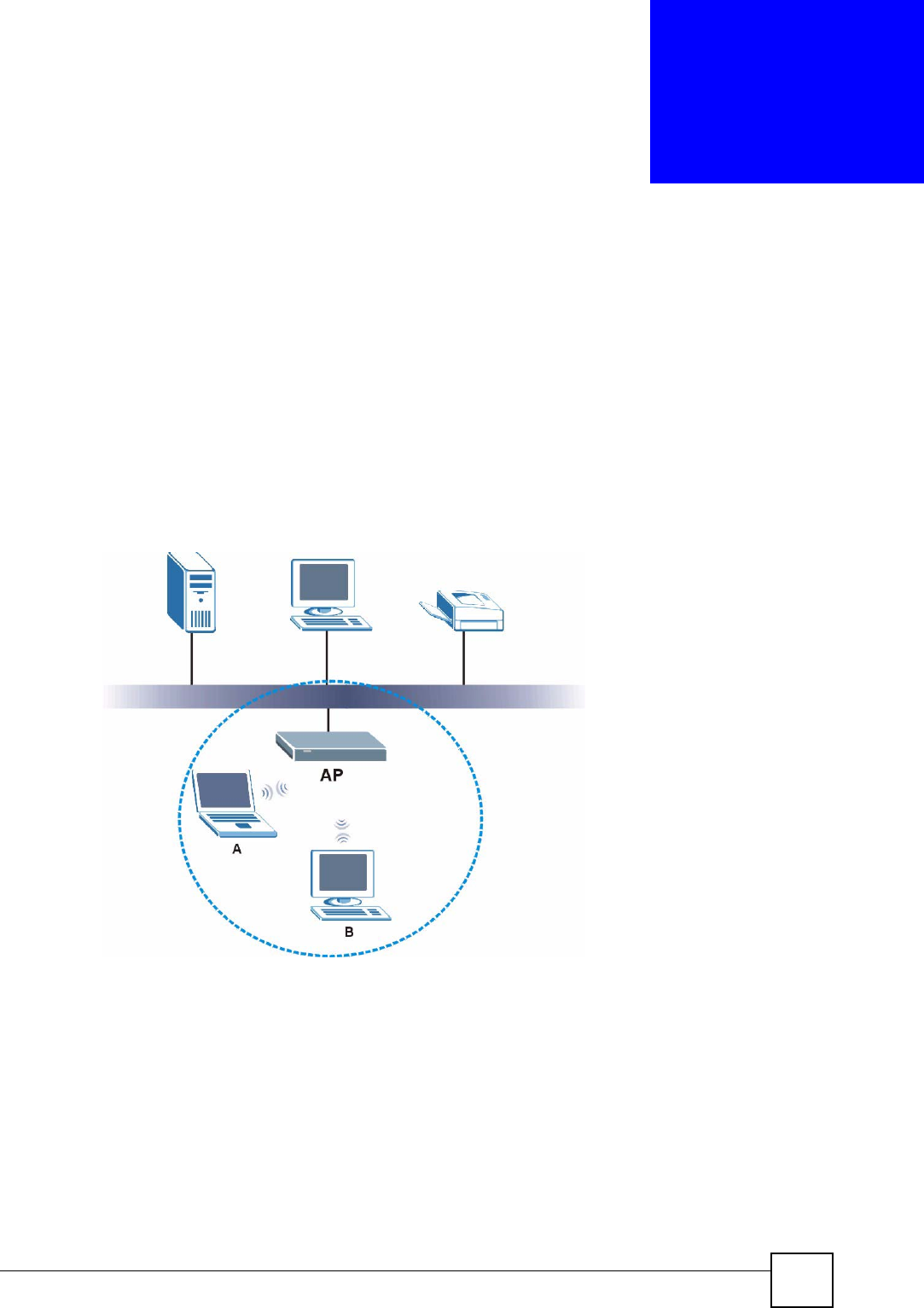
Figure 33 Example of a Wireless Network
The wireless network is the part in the blue circle. In this wireless network, devices A and B
are called wireless clients. The wireless clients use the access point (AP) to interact with other
devices (such as the printer) or with the Internet. Your NBG334W is the AP.
Every wireless network must follow these basic guidelines.
• Every wireless client in the same wireless network must use the same SSID.
The SSID is the name of the wireless network. It stands for Service Set IDentity.
• If two wireless networks overlap, they should use different channels.
Like radio stations or television channels, each wireless network uses a specific channel,
or frequency, to send and receive information.

Chapter 5 Wireless LAN
NBG334W User’s Guide
70
• Every wireless client in the same wireless network must use security compatible with the
AP.
Security stops unauthorized devices from using the wireless network. It can also protect
the information that is sent in the wireless network.
Requirements
To add a wireless LAN to your existing network, make sure you have the following:
1an access point (AP) or a router with the wireless feature
2at least one wireless network card/adapter which varies according to your computer.
•If you have a desktop, use either a wireless USB adapter or a wireless PCI adapter.
•If you have a laptop, use either a wireless USB adapter or a wireless CardBus card.
3a RADIUS server only if you want to use IEEE802.1x, WPA or WPA2
To have two or more computers communicate with each other wirelessly without an AP or
wireless router, make sure you have the following:
1two or more wireless network cards/adapters which vary according to your computers.
•If you have a desktop, use either a wireless USB adapter or a wireless PCI adapter.
•If you have a laptop, use either a wireless USB adapter or a wireless CardBus card.
Setup Information
To set up your wireless network using an AP or wireless router, make sure your AP or wireless
router and wireless network card(s)/adapter(s) use the same following settings:
• SSID:_____________________
• Channel: auto or _________
• Network type of a wireless network card/adapter: Infrastructure
• wireless standard: IEEE 802.11b, g, b/g or a
• Security:
( ) None
( ) WEP (64bit, 128bit or 256bit key) (ASCII or Hex):________________
( ) IEEE 802.1x
( ) WPA-PSK (TKIP or AES):_______________
( ) WPA (TKIP or AES)
( ) WPA2-PSK (TKIP or AES):______________
( ) WPA2 (TKIP or AES)

Chapter 5 Wireless LAN
NBG334W User’s Guide 71
• Preamble type (if available): auto, short or long
To set up your wireless network without an AP or wireless router, make sure wireless network
cards/adapters use the same following settings:
• Network type: Ad-Hoc
• SSID:_____________________
• Channel: _________________
• wireless standard: IEEE 802.11b, g, b/g or a
• Security:
( ) None
( ) WEP (64bit, 128bit or 256bit key) (ASCII or Hex):________________
5.2 Wireless Security Overview
The following sections introduce different types of wireless security you can set up in the
wireless network.
5.2.1 SSID
Normally, the AP acts like a beacon and regularly broadcasts the SSID in the area. You can
hide the SSID instead, in which case the AP does not broadcast the SSID. In addition, you
should change the default SSID to something that is difficult to guess.
This type of security is fairly weak, however, because there are ways for unauthorized devices
to get the SSID. In addition, unauthorized devices can still see the information that is sent in
the wireless network.
5.2.2 MAC Address Filter
Every wireless client has a unique identification number, called a MAC address.1 A MAC
address is usually written using twelve hexadecimal characters2; for example, 00A0C5000002
or 00:A0:C5:00:00:02. To get the MAC address for each wireless client, see the appropriate
User’s Guide or other documentation.
You can use the MAC address filter to tell the AP which wireless clients are allowed or not
allowed to use the wireless network. If a wireless client is allowed to use the wireless network,
it still has to have the correct settings (SSID, channel, and security). If a wireless client is not
allowed to use the wireless network, it does not matter if it has the correct settings.
This type of security does not protect the information that is sent in the wireless network.
Furthermore, there are ways for unauthorized devices to get the MAC address of an authorized
wireless client. Then, they can use that MAC address to use the wireless network.
1. Some wireless devices, such as scanners, can detect wireless networks but cannot use wireless networks.
These kinds of wireless devices might not have MAC addresses.
2. Hexadecimal characters are 0, 1, 2, 3, 4, 5, 6, 7, 8, 9, A, B, C, D, E, and F.

Chapter 5 Wireless LAN
NBG334W User’s Guide
72
5.2.3 User Authentication
You can make every user log in to the wireless network before they can use it. This is called
user authentication. However, every wireless client in the wireless network has to support
IEEE 802.1x to do this.
For wireless networks, there are two typical places to store the user names and passwords for
each user.
• In the AP: this feature is called a local user database or a local database.
• In a RADIUS server: this is a server used in businesses more than in homes.
If your AP does not provide a local user database and if you do not have a RADIUS server,
you cannot set up user names and passwords for your users.
Unauthorized devices can still see the information that is sent in the wireless network, even if
they cannot use the wireless network. Furthermore, there are ways for unauthorized wireless
users to get a valid user name and password. Then, they can use that user name and password
to use the wireless network.
Local user databases also have an additional limitation that is explained in the next section.
5.2.4 Encryption
Wireless networks can use encryption to protect the information that is sent in the wireless
network. Encryption is like a secret code. If you do not know the secret code, you cannot
understand the message.
The types of encryption you can choose depend on the type of user authentication. (See
Section 5.2.3 on page 72 for information about this.)
For example, if the wireless network has a RADIUS server, you can choose WPA or WPA2.
If users do not log in to the wireless network, you can choose no encryption, Static WEP,
WPA-PSK, or WPA2-PSK.
Usually, you should set up the strongest encryption that every wireless client in the wireless
network supports. For example, suppose the AP does not have a local user database, and you
do not have a RADIUS server. Therefore, there is no user authentication. Suppose the wireless
network has two wireless clients. Device A only supports WEP, and device B supports WEP
and WPA. Therefore, you should set up Static WEP in the wireless network.
Table 25 Types of Encryption for Each Type of Authentication
NO AUTHENTICATION RADIUS SERVER
Weakest No Security WPA
Static WEP
WPA-PSK
Strongest WPA2-PSK WPA2

Chapter 5 Wireless LAN
NBG334W User’s Guide 73
"It is recommended that wireless networks use WPA-PSK, WPA, or stronger
encryption. IEEE 802.1x and WEP encryption are better than none at all, but it
is still possible for unauthorized devices to figure out the original information
pretty quickly.
It is not possible to use WPA-PSK, WPA or stronger encryption with a local
user database. In this case, it is better to set up stronger encryption with no
authentication than to set up weaker encryption with the local user database.
When you select WPA2 or WPA2-PSK in your NBG334W, you can also select an option
(WPA Compatible) to support WPA as well. In this case, if some wireless clients support
WPA and some support WPA2, you should set up WPA2-PSK or WPA2 (depending on the
type of wireless network login) and select the WPA Compatible option in the NBG334W.
Many types of encryption use a key to protect the information in the wireless network. The
longer the key, the stronger the encryption. Every wireless client in the wireless network must
have the same key.
5.3 Roaming
A wireless station is a device with an IEEE 802.11a/b/g compliant wireless interface. An
access point (AP) acts as a bridge between the wireless and wired networks. An AP creates its
own wireless coverage area. A wireless station can associate with a particular access point
only if it is within the access point’s coverage area.
In a network environment with multiple access points, wireless stations are able to switch from
one access point to another as they move between the coverage areas. This is known as
roaming. As the wireless station moves from place to place, it is responsible for choosing the
most appropriate access point depending on the signal strength, network utilization or other
factors.
The roaming feature on the access points allows the access points to relay information about
the wireless stations to each other. When a wireless station moves from a coverage area to
another, it scans and uses the channel of a new access point, which then informs the other
access points on the LAN about the change. An example is shown in Figure 34 on page 74.
With roaming, a wireless LAN mobile user enjoys a continuous connection to the wired
network through an access point while moving around the wireless LAN.
Enable roaming to exchange the latest bridge information of all wireless stations between APs
when a wireless station moves between coverage areas. Wireless stations can still associate
with other APs even if you disable roaming. Enabling roaming ensures correct traffic
forwarding (bridge tables are updated) and maximum AP efficiency. The AP deletes records
of wireless stations that associate with other APs (Non-ZyXEL APs may not be able to
perform this). 802.1x authentication information is not exchanged (at the time of writing).
Chapter 5 Wireless LAN
NBG334W User’s Guide
74
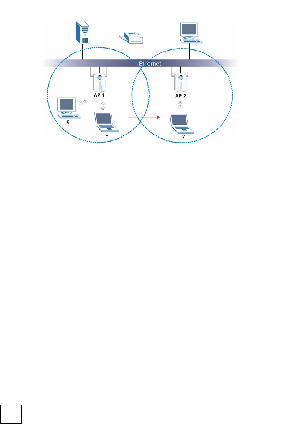
Figure 34 Roaming Example
The steps below describe the roaming process.
1Wireless station Y moves from the coverage area of access point AP 1 to that of access
point AP 2.
2Wireless station Y scans and detects the signal of access point AP 2.
3Wireless station Y sends an association request to access point AP 2.
4Access point AP 2 acknowledges the presence of wireless station Y and relays this
information to access point AP 1 through the wired LAN.
5Access point AP 1 updates the new position of wireless station Y.
5.3.1 Requirements for Roaming
The following requirements must be met in order for wireless stations to roam between the
coverage areas.
1All the access points must be on the same subnet and configured with the same ESSID.
2If IEEE 802.1x user authentication is enabled and to be done locally on the access point,
the new access point must have the user profile for the wireless station.
3The adjacent access points should use different radio channels when their coverage areas
overlap.
4All access points must use the same port number to relay roaming information.
5The access points must be connected to the Ethernet and be able to get IP addresses from
a DHCP server if using dynamic IP address assignment.
5.4 Quality of Service
This section discusses the Quality of Service (QoS) features available on the NBG334W.

Chapter 5 Wireless LAN
NBG334W User’s Guide 75
5.4.1 WMM QoS
WMM (Wi-Fi MultiMedia) QoS (Quality of Service) ensures quality of service in wireless
networks. It controls WLAN transmission priority on packets to be transmitted over the
wireless network.
WMM QoS prioritizes wireless traffic according to delivery requirements. WMM QoS is a
part of the IEEE 802.11e QoS enhancement to certified Wi-Fi wireless networks.
On APs without WMM QoS, all traffic streams are given the same access priority to the
wireless network. If the introduction of another traffic stream creates a data transmission
demand that exceeds the current network capacity, then the new traffic stream reduces the
throughput of the other traffic streams.
The NBG334W uses WMM QoS to prioritize traffic streams according to the IEEE 802.1q tag
or DSCP information in each packet’s header. The NBG334W automatically determines the
priority to use for an individual traffic stream. This prevents reductions in data transmission
for applications that are sensitive to latency (delay) and jitter (variations in delay).
5.4.1.1 WMM QoS Priorities
The following table describes the WMM QoS priority levels that the NBG334W uses.
5.5 General Wireless LAN Screen
"If you are configuring the NBG334W from a computer connected to the
wireless LAN and you change the NBG334W’s SSID, channel or security
settings, you will lose your wireless connection when you press Apply to
confirm. You must then change the wireless settings of your computer to
match the NBG334W’s new settings.
Click Network > Wireless LAN to open the General screen.
Table 26 WMM QoS Priorities
PRIORITY LEVEL DESCRIPTION
voice
(WMM_VOICE)
Typically used for traffic that is especially sensitive to jitter. Use this priority
to reduce latency for improved voice quality.
video
(WMM_VIDEO)
Typically used for traffic which has some tolerance for jitter but needs to be
prioritized over other data traffic.
best effort
(WMM_BEST_EFFORT)
Typically used for traffic from applications or devices that lack QoS
capabilities. Use best effort priority for traffic that is less sensitive to latency,
but is affected by long delays, such as Internet surfing.
background
(WMM_BACKGROUND)
This is typically used for non-critical traffic such as bulk transfers and print
jobs that are allowed but that should not affect other applications and users.
Use background priority for applications that do not have strict latency and
throughput requirements.
Chapter 5 Wireless LAN
NBG334W User’s Guide
76
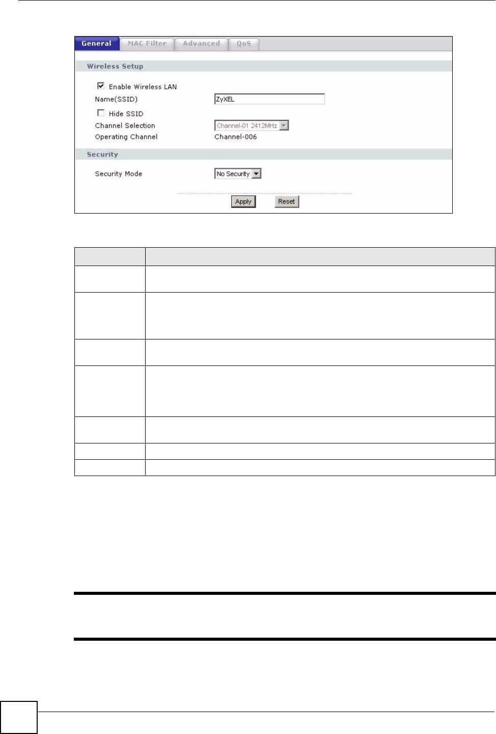
Figure 35 Network > Wireless LAN > General
The following table describes the general wireless LAN labels in this screen.
See the rest of this chapter for information on the other labels in this screen.
5.5.1 No Security
Select No Security to allow wireless stations to communicate with the access points without
any data encryption.
"If you do not enable any wireless security on your NBG334W, your network is
accessible to any wireless networking device that is within range.
Table 27 Network > Wireless LAN > General
LABEL DESCRIPTION
Enable
Wireless LAN
Click the check box to activate wireless LAN.
Name(SSID) (Service Set IDentity) The SSID identifies the Service Set with which a wireless
station is associated. Wireless stations associating to the access point (AP) must
have the same SSID. Enter a descriptive name (up to 32 printable 7-bit ASCII
characters) for the wireless LAN.
Hide SSID Select this check box to hide the SSID in the outgoing beacon frame so a station
cannot obtain the SSID through scanning using a site survey tool.
Channel
Selection
Set the operating frequency/channel depending on your particular region.
Select a channel from the drop-down list box. The options vary depending on
whether you are using A or B/G frequency band and the country you are in.
Refer to the Connection Wizard chapter for more information on channels.
Operating
Channel
This displays the channel the NBG334W is currently using.
Apply Click Apply to save your changes back to the NBG334W.
Reset Click Reset to reload the previous configuration for this screen.
Chapter 5 Wireless LAN
NBG334W User’s Guide 77
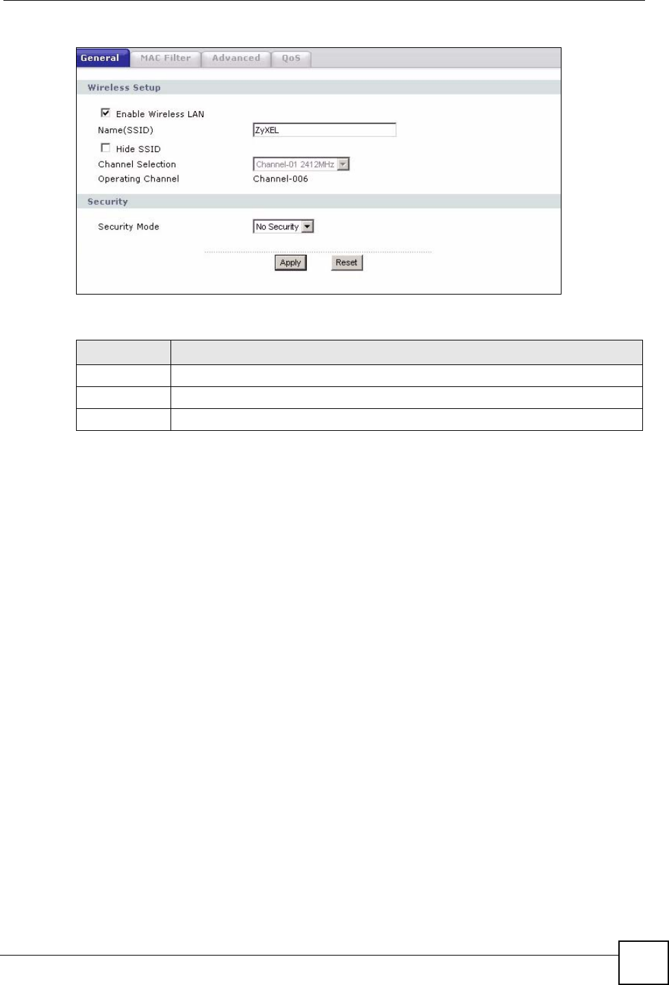
Figure 36 Network > Wireless LAN > General: No Security
The following table describes the labels in this screen.
5.5.2 WEP Encryption
WEP encryption scrambles the data transmitted between the wireless stations and the access
points to keep network communications private. It encrypts unicast and multicast
communications in a network. Both the wireless stations and the access points must use the
same WEP key.
Your NBG334W allows you to configure up to four 64-bit or 128-bit WEP keys but only one
key can be enabled at any one time.
In order to configure and enable WEP encryption; click Network > Wireless LAN to display
the General screen. Select Static WEP from the Security Mode list.
Table 28 Wireless No Security
LABEL DESCRIPTION
Security Mode Choose No Security from the drop-down list box.
Apply Click Apply to save your changes back to the NBG334W.
Reset Click Reset to reload the previous configuration for this screen.
Chapter 5 Wireless LAN
NBG334W User’s Guide
78
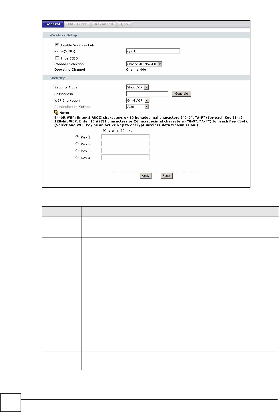
Figure 37 Network > Wireless LAN > General: Static WEP
The following table describes the wireless LAN security labels in this screen.
Table 29 Network > Wireless LAN > General: Static WEP
LABEL DESCRIPTION
Passphrase Enter a passphrase (password phrase) of up to 32 printable characters and click
Generate. The NBG334W automatically generates four different WEP keys and
displays them in the Key fields below.
WEP
Encryption
Select 64-bit WEP or 128-bit WEP to enable data encryption.
Authentication
Method
This field is activated when you select 64-bit WEP or 128-bit WEP in the WEP
Encryption field.
Select Auto, Open System or Shared Key from the drop-down list box.
ASCII Select this option in order to enter ASCII characters as WEP key.
Hex Select this option in order to enter hexadecimal characters as a WEP key.
The preceding "0x", that identifies a hexadecimal key, is entered automatically.
Key 1 to Key 4 The WEP keys are used to encrypt data. Both the NBG334W and the wireless
stations must use the same WEP key for data transmission.
If you chose 64-bit WEP, then enter any 5 ASCII characters or 10 hexadecimal
characters ("0-9", "A-F").
If you chose 128-bit WEP, then enter 13 ASCII characters or 26 hexadecimal
characters ("0-9", "A-F").
You must configure at least one key, only one key can be activated at any one time.
The default key is key 1.
Apply Click Apply to save your changes back to the NBG334W.
Reset Click Reset to reload the previous configuration for this screen.
Chapter 5 Wireless LAN
NBG334W User’s Guide 79
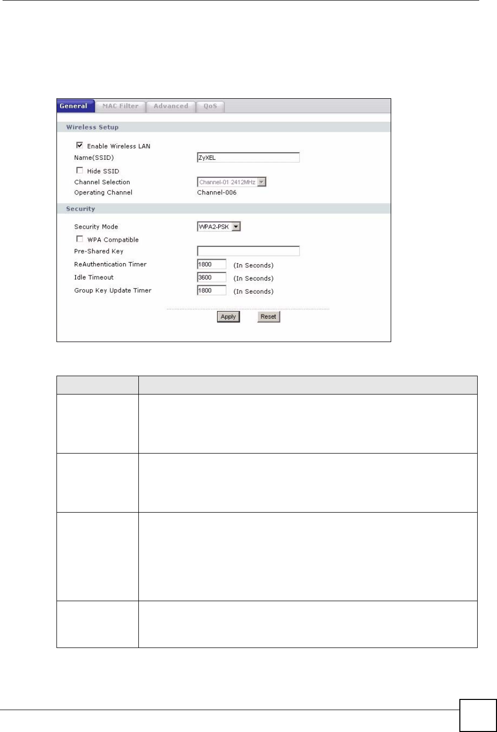
5.5.3 WPA-PSK/WPA2-PSK
Click Network > Wireless LAN to display the General screen. Select WPA-PSK or WPA2-
PSK from the Security Mode list.
Figure 38 Network > Wireless LAN > General: WPA-PSK/WPA2-PSK
The following table describes the labels in this screen.
Table 30 Network > Wireless LAN > General: WPA-PSK/WPA2-PSK
LABEL DESCRIPTION
WPA Compatible This check box is available only when you select WPA2-PSK or WPA2 in the
Security Mode field.
Select the check box to have both WPA2 and WPA wireless clients be able to
communicate with the NBG334W even when the NBG334W is using WPA2-PSK
or WPA2.
Pre-Shared Key The encryption mechanisms used for WPA/WPA2 and WPA-PSK/WPA2-PSK
are the same. The only difference between the two is that WPA-PSK/WPA2-PSK
uses a simple common password, instead of user-specific credentials.
Type a pre-shared key from 8 to 63 case-sensitive ASCII characters (including
spaces and symbols).
ReAuthentication
Timer (in
seconds)
Specify how often wireless stations have to resend usernames and passwords in
order to stay connected. Enter a time interval between 10 and 9999 seconds. The
default time interval is 1800 seconds (30 minutes).
Note: If wireless station authentication is done using a RADIUS
server, the reauthentication timer on the RADIUS server has
priority.
Idle Timeout The NBG334W automatically disconnects a wireless station from the wired
network after a period of inactivity. The wireless station needs to enter the
username and password again before access to the wired network is allowed. The
default time interval is 3600 seconds (or 1 hour).
Chapter 5 Wireless LAN
NBG334W User’s Guide
80
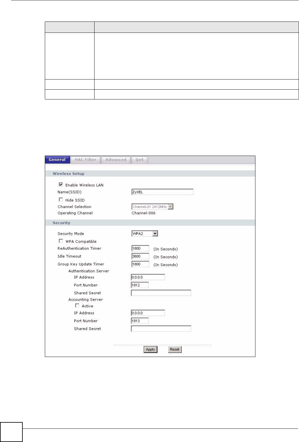
5.5.4 WPA/WPA2
Click Network > Wireless LAN to display the General screen. Select WPA or WPA2 from
the Security Mode list.
Figure 39 Network > Wireless LAN > General: WPA/WPA2
Group Key
Update Timer
The Group Key Update Timer is the rate at which the AP (if using WPA-PSK/
WPA2-PSK key management) or RADIUS server (if using WPA/WPA2 key
management) sends a new group key out to all clients. The re-keying process is
the WPA/WPA2 equivalent of automatically changing the WEP key for an AP and
all stations in a WLAN on a periodic basis. Setting of the Group Key Update
Timer is also supported in WPA-PSK/WPA2-PSK mode. The default is 1800
seconds (30 minutes).
Apply Click Apply to save your changes back to the NBG334W.
Reset Click Reset to reload the previous configuration for this screen.
Table 30 Network > Wireless LAN > General: WPA-PSK/WPA2-PSK
LABEL DESCRIPTION

Chapter 5 Wireless LAN
NBG334W User’s Guide 81
The following table describes the labels in this screen.
Table 31 Network > Wireless LAN > General: WPA/WPA2
LABEL DESCRIPTION
WPA Compatible This check box is available only when you select WPA2-PSK or WPA2 in the
Security Mode field.
Select the check box to have both WPA2 and WPA wireless clients be able to
communicate with the NBG334W even when the NBG334W is using WPA2-PSK
or WPA2.
ReAuthentication
Timer (in seconds)
Specify how often wireless stations have to resend usernames and passwords in
order to stay connected. Enter a time interval between 10 and 9999 seconds.
The default time interval is 1800 seconds (30 minutes).
Note: If wireless station authentication is done using a RADIUS
server, the reauthentication timer on the RADIUS server
has priority.
Idle Timeout The NBG334W automatically disconnects a wireless station from the wired
network after a period of inactivity. The wireless station needs to enter the
username and password again before access to the wired network is allowed.
The default time interval is 3600 seconds (or 1 hour).
Group Key Update
Timer
The Group Key Update Timer is the rate at which the AP (if using WPA-PSK/
WPA2-PSK key management) or RADIUS server (if using WPA/WPA2 key
management) sends a new group key out to all clients. The re-keying process is
the WPA/WPA2 equivalent of automatically changing the WEP key for an AP
and all stations in a WLAN on a periodic basis. Setting of the Group Key Update
Timer is also supported in WPA-PSK/WPA2-PSK mode. The NBG334W default
is 1800 seconds (30 minutes).
Authentication Server
IP Address Enter the IP address of the external authentication server in dotted decimal
notation.
Port Number Enter the port number of the external authentication server. The default port
number is 1812.
You need not change this value unless your network administrator instructs you
to do so with additional information.
Shared Secret Enter a password (up to 31 alphanumeric characters) as the key to be shared
between the external authentication server and the NBG334W.
The key must be the same on the external authentication server and your
NBG334W. The key is not sent over the network.
Accounting Server
Active Select Yes from the drop down list box to enable user accounting through an
external authentication server.
IP Address Enter the IP address of the external accounting server in dotted decimal notation.
Port Number Enter the port number of the external accounting server. The default port number
is 1813.
You need not change this value unless your network administrator instructs you
to do so with additional information.
Shared Secret Enter a password (up to 31 alphanumeric characters) as the key to be shared
between the external accounting server and the NBG334W.
The key must be the same on the external accounting server and your
NBG334W. The key is not sent over the network.
Apply Click Apply to save your changes back to the NBG334W.
Reset Click Reset to reload the previous configuration for this screen.
Chapter 5 Wireless LAN
NBG334W User’s Guide
82
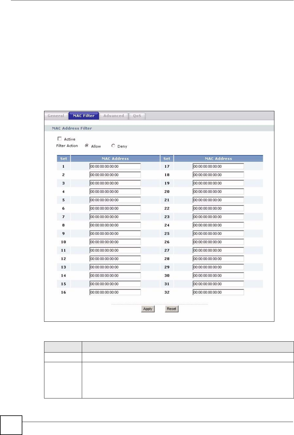
5.6 MAC Filter
The MAC filter screen allows you to configure the NBG334W to give exclusive access to up
to 32 devices (Allow) or exclude up to 32 devices from accessing the NBG334W (Deny).
Every Ethernet device has a unique MAC (Media Access Control) address. The MAC address
is assigned at the factory and consists of six pairs of hexadecimal characters, for example,
00:A0:C5:00:00:02. You need to know the MAC address of the devices to configure this
screen.
To change your NBG334W’s MAC filter settings, click Network > Wireless LAN > MAC
Filter. The screen appears as shown.
Figure 40 Network > Wireless LAN > MAC Filter
The following table describes the labels in this menu.
Table 32 Network > Wireless LAN > MAC Filter
LABEL DESCRIPTION
Active Select Yes from the drop down list box to enable MAC address filtering.
Filter Action Define the filter action for the list of MAC addresses in the MAC Address table.
Select Deny to block access to the NBG334W, MAC addresses not listed will be
allowed to access the NBG334W
Select Allow to permit access to the NBG334W, MAC addresses not listed will be
denied access to the NBG334W.
Chapter 5 Wireless LAN
NBG334W User’s Guide 83
5.7 Wireless LAN Advanced Screen
Click Network > Wireless LAN > Advanced. The screen appears as shown.
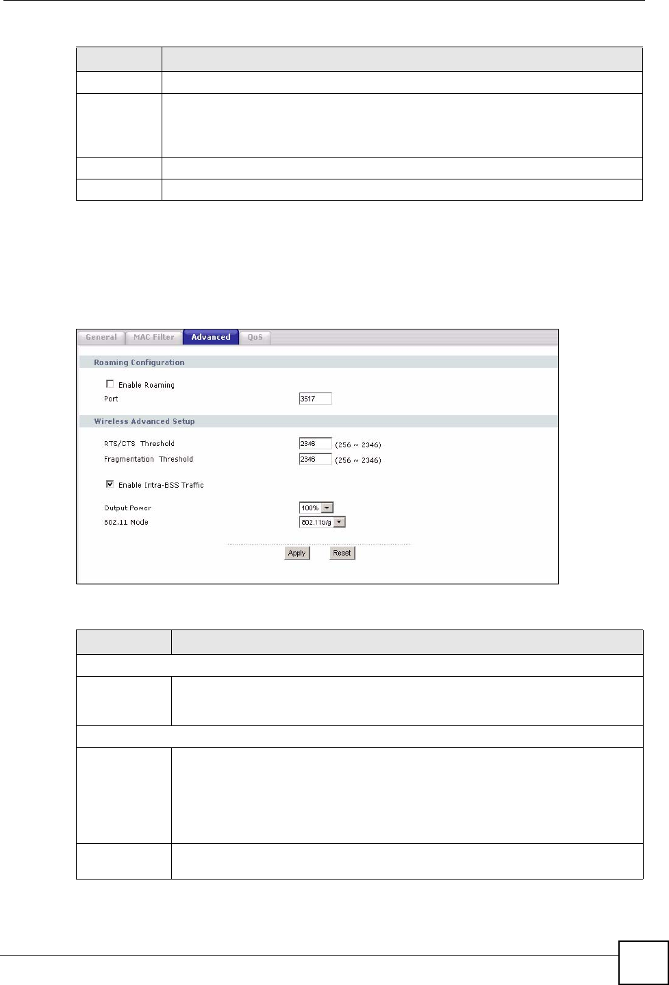
Figure 41 Network > Wireless LAN > Advanced
The following table describes the labels in this screen.
Set This is the index number of the MAC address.
MAC
Address
Enter the MAC addresses of the wireless station that are allowed or denied access to
the NBG334W in these address fields. Enter the MAC addresses in a valid MAC
address format, that is, six hexadecimal character pairs, for example,
12:34:56:78:9a:bc.
Apply Click Apply to save your changes back to the NBG334W.
Reset Click Reset to reload the previous configuration for this screen.
Table 32 Network > Wireless LAN > MAC Filter
LABEL DESCRIPTION
Table 33 Network > Wireless LAN > Advanced
LABEL DESCRIPTION
Roaming Configuration
Enable
Roaming
Select this option if your network environment has multiple APs and you want your
wireless device to be able to access the network as you move between wireless
networks.
Wireless Advanced Setup
RTS/CTS
Threshold
Data with its frame size larger than this value will perform the RTS (Request To
Send)/CTS (Clear To Send) handshake.
If the RTS/CTS value is greater than the Fragmentation Threshold value, then the
RTS/CTS handshake will never occur as data frames will be fragmented before they
reach RTS/CTS size.
Enter a value between 0 and 2432.
Fragmentation
Threshold
It is the maximum data fragment size that can be sent. Enter a value between 256
and 2432.

Chapter 5 Wireless LAN
NBG334W User’s Guide
84
5.8 Quality of Service (QoS) Screen
The QoS screen allows you to automatically give a service (such as e-mail, VoIP or FTP) a
priority level.
Click Network > Wireless LAN > QoS. The following screen appears.
Enable Intra-
BSS Traffic
A Basic Service Set (BSS) exists when all communications between wireless clients
or between a wireless client and a wired network client go through one access point
(AP).
Intra-BSS traffic is traffic between wireless clients in the BSS. When Intra-BSS is
enabled, wireless client A and B can access the wired network and communicate
with each other. When Intra-BSS is disabled, wireless client A and B can still access
the wired network but cannot communicate with each other.
Output Power Set the output power of the NBG334W in this field. If there is a high density of APs
within an area, decrease the output power of the NBG334W to reduce interference
with other APs.
802.11 Mode Select 802.11b to allow only IEEE 802.11b compliant WLAN devices to associate
with the NBG334W.
Select 802.11g to allow only IEEE 802.11g compliant WLAN devices to associate
with the NBG334W.
Select 802.11b/g to allow either IEEE802.11b or IEEE802.11g compliant WLAN
devices to associate with the NBG334W. The transmission rate of your NBG334W
might be reduced.
Apply Click Apply to save your changes back to the NBG334W.
Reset Click Reset to reload the previous configuration for this screen.
Table 33 Network > Wireless LAN > Advanced
LABEL DESCRIPTION
Chapter 5 Wireless LAN
NBG334W User’s Guide 85
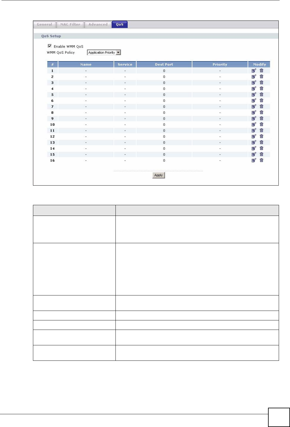
Figure 42 Network > Wireless LAN > QoS
The following table describes the labels in this screen.
Table 34 Network > Wireless LAN > QoS
LABEL DESCRIPTION
Enable WMM QoS Select this to turn on WMM QoS (Wireless MultiMedia Quality of
Service). The NBG334W assigns priority to packets based on the
802.1q or DSCP information in their headers. If a packet has no
WMM information in its header, it is assigned the default priority.
WMM QoS Policy Select Default to have the NBG334W automatically give a service
a priority level according to the ToS value in the IP header of
packets it sends. WMM QoS (Wifi MultiMedia Quality of Service)
gives high priority to voice and video, which makes them run more
smoothly.
Select Application Priority from the drop-down list box to display a
table of application names, services, ports and priorities to which
you want to apply WMM QoS.
The table appears only if you select Application Priority in WMM
QoS Policy.
# This is the number of an individual application entry.
Name This field displays a description given to an application entry.
Service This field displays either FTP, WWW, E-mail or a User Defined
service to which you want to apply WMM QoS.
Dest Port This field displays the destination port number to which the
application sends traffic.
Chapter 5 Wireless LAN
NBG334W User’s Guide
86
5.8.1 Application Priority Configuration
Use this screen to edit a WMM QoS application entry. Click the edit icon under Modify. The
following screen displays.
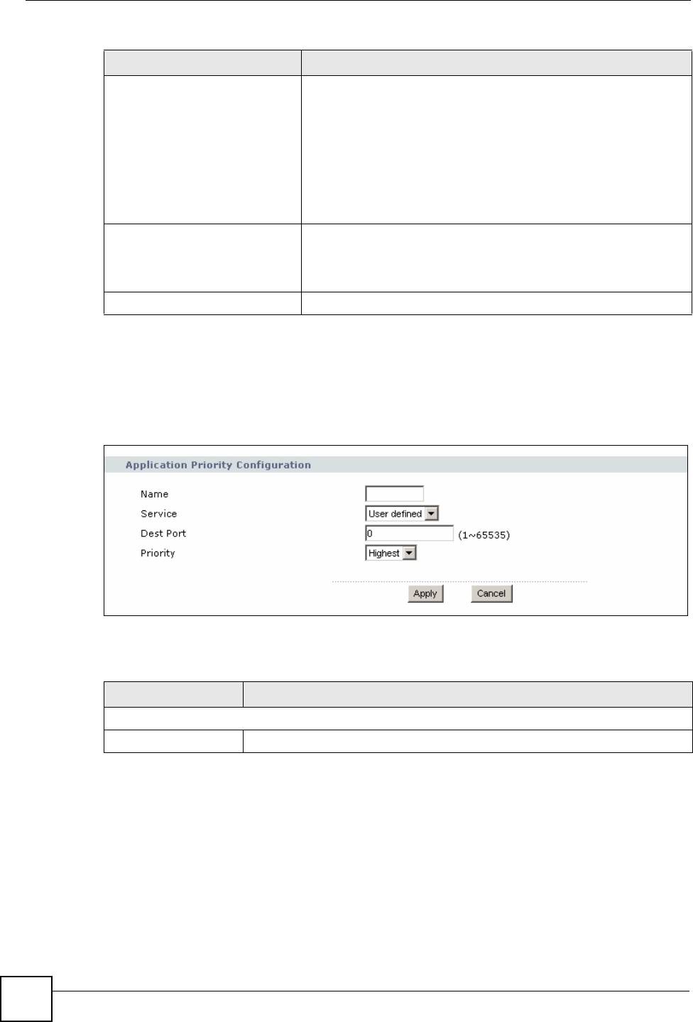
Figure 43 Network > Wireless LAN > QoS: Application Priority Configuration
See Appendix F on page 259 for a list of commonly-used services and destination ports. The
following table describes the fields in this screen.
Priority This field displays the priority of the application.
Highest - Typically used for voice or video that should be high-
quality.
High - Typically used for voice or video that can be medium-quality.
Mid - Typically used for applications that do not fit into another
priority. For example, Internet surfing.
Low - Typically used for non-critical “background” applications,
such as large file transfers and print jobs that should not affect
other applications.
Modify Click the Edit icon to open the Application Priority Configuration
screen. Modify an existing application entry or create a application
entry in the Application Priority Configuration screen.
Click the Remove icon to delete an application entry.
Apply Click Apply to save your changes to the NBG334W.
Table 34 Network > Wireless LAN > QoS (continued)
LABEL DESCRIPTION
Table 35 Network > Wireless LAN > QoS: Application Priority Configuration
LABEL DESCRIPTION
Application Priority Configuration
Name Type a description of the application priority.

Chapter 5 Wireless LAN
NBG334W User’s Guide 87
Service The following is a description of the applications you can prioritize with WMM
QoS. Select a service from the drop-down list box.
• E-Mail
Electronic mail consists of messages sent through a computer network to
specific groups or individuals. Here are some default ports for e-mail:
POP3 - port 110
IMAP - port 143
SMTP - port 25
HTTP - port 80
•FTP
File Transfer Protocol enables fast transfer of files, including large files that it
may not be possible to send via e-mail. FTP uses port number 21.
•WWW
The World Wide Web is an Internet system to distribute graphical, hyper-
linked information, based on Hyper Text Transfer Protocol (HTTP) - a client/
server protocol for the World Wide Web. The Web is not synonymous with the
Internet; rather, it is just one service on the Internet. Other services on the
Internet include Internet Relay Chat and Newsgroups. The Web is accessed
through use of a browser.
•User-Defined
User-defined services are user specific services configured using known ports
and applications.
Dest Port This displays the port the selected service uses. Type a port number in the
field provided if you want to use a different port to the default port.
Priority Select a priority from the drop-down list box.
Apply Click Apply to save your changes back to the NBG334W.
Cancel Click Cancel to return to the previous screen.
Table 35 Network > Wireless LAN > QoS: Application Priority Configuration (continued)
LABEL DESCRIPTION

Chapter 5 Wireless LAN
NBG334W User’s Guide
88
NBG334W User’s Guide 89
CHAPTER 6
Wireless Tutorial
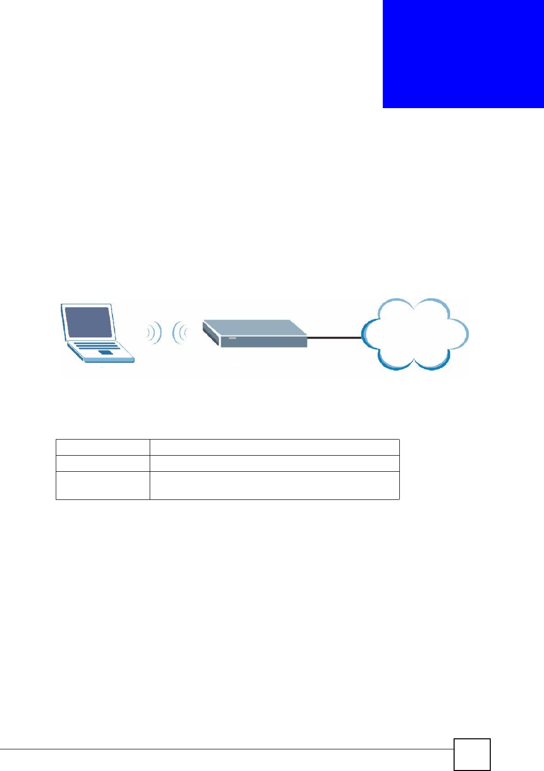
6.1 How to Connect to the Internet from a Notebook
This section gives you an example of how to set up an access point and wireless client such as
a notebook for wireless communication. The notebook (N) can access the Internet through an
AP wirelessly.
Figure 44 Wireless AP Connection to the Internet
6.1.1 Example Parameters
An access point or wireless router is referred to as an “AP” and a computer with a wireless
network card or USB/PCI adapter is referred to as a “wireless client” here.
6.2 Enable and Configure Wireless Security on your
NBG334W
Follow the steps below to configure the wireless settings on your NBG334W.
The instructions require that your hardware is connected (see the Quick Start Guide) and you
are logged into the web configurator through your LAN connection (see Section 2.2 on page
33).
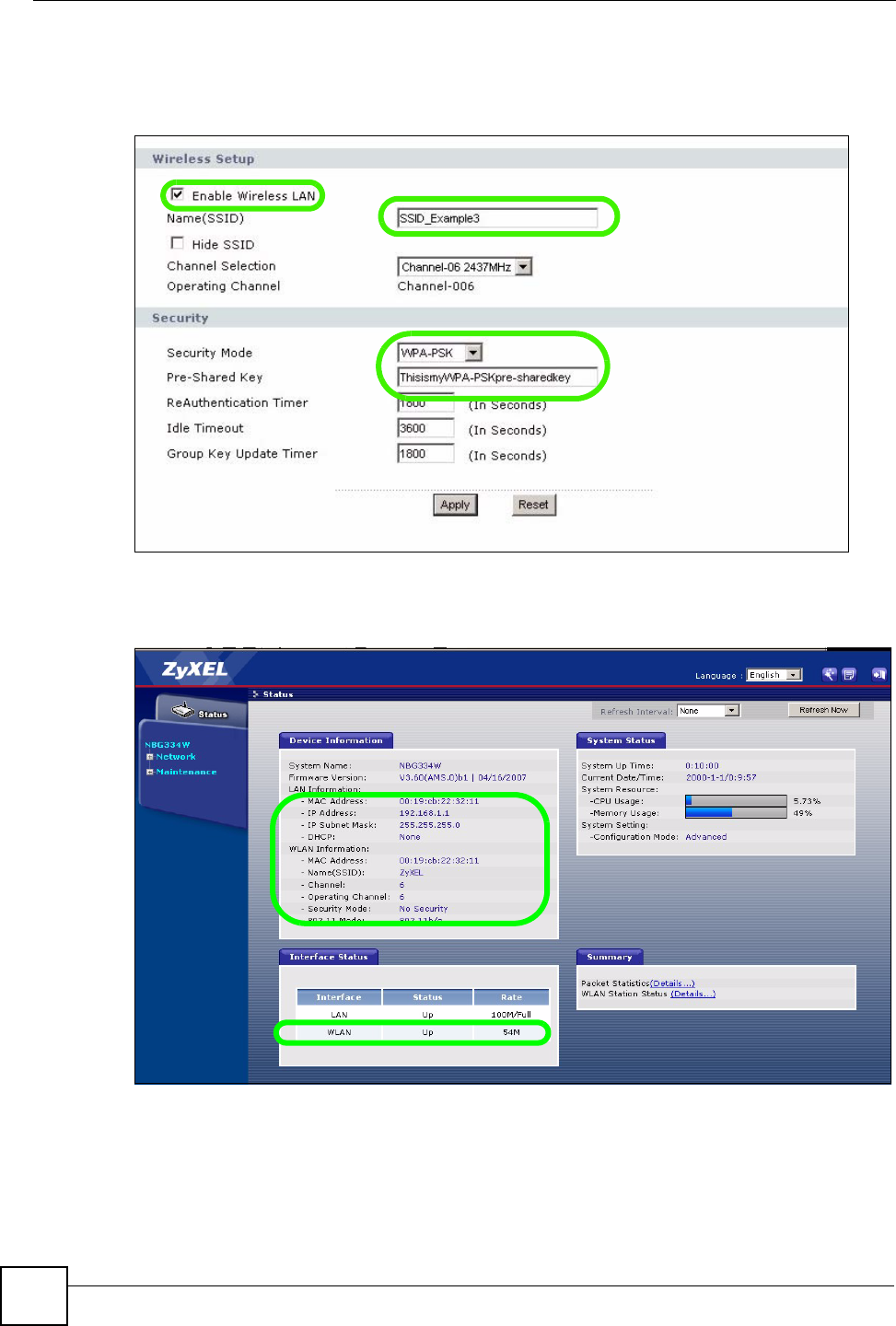
1Open the Wireless LAN > General screen in the AP’s web configurator.
2Make sure the Enable Wireless LAN check box is selected.
3Enter SSID_Example3 as the SSID and select a channel.
N
AP
Internet
SSID SSID_Example3
Channel 6
Security WPA-PSK
(Pre-Shared Key: ThisismyWPA-PSKpre-sharedkey)
Chapter 6 Wireless Tutorial
NBG334W User’s Guide
90
4Set security mode to WPA-PSK and enter ThisismyWPA-PSKpre-sharedkey in the
Pre-Shared Key field. Click Apply.
Figure 45 Network > Wireless LAN > General
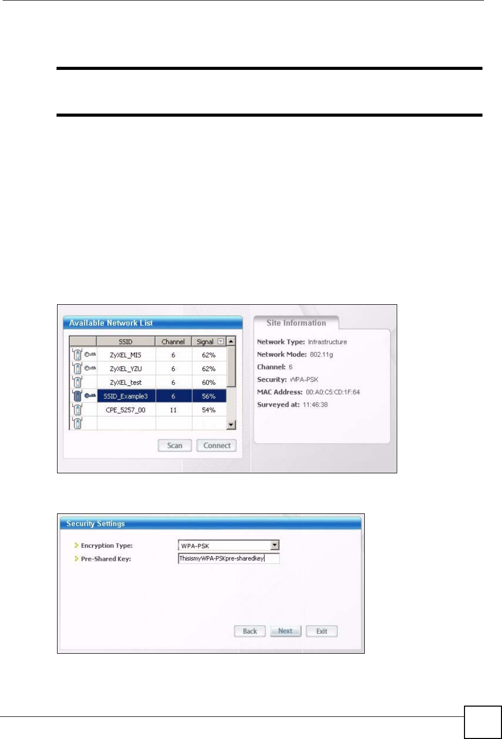
5Open the Status screen. Verify your wireless and wireless security settings under Device
Information and check if the WLAN connection is up under Interface Status.
Figure 46 Status: AP Mode
Chapter 6 Wireless Tutorial
NBG334W User’s Guide 91
6.3 Configure Your Notebook
"We use the ZyXEL M-302 wireless adapter utility screens as an example for
the wireless client. The screens may vary for different models.
1The NBG334W supports IEEE 802.11b and IEEE 802.11g wireless clients. Make sure
that your notebook or computer’s wireless adapter supports one of these standards.
2Wireless adapters come with software sometimes called a “utility” that you install on
your computer. See your wireless adapter’s User’s Guide for information on how to do
that.
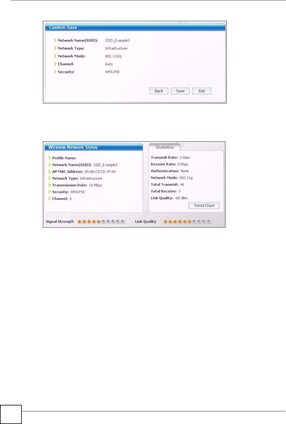
3After you’ve installed the utility, open it. If you cannot see your utility’s icon on your
screen, go to Start > Programs and click on your utility in the list of programs that
appears. The utility displays a list of APs within range, as shown in the example screen
below.
4Select SSID_Example3 and click Connect.
Figure 47 Connecting a Wireless Client to a Wireless Network t
5Select WPA-PSK and type the security key in the following screen. Click Next.
Figure 48 Security Settings
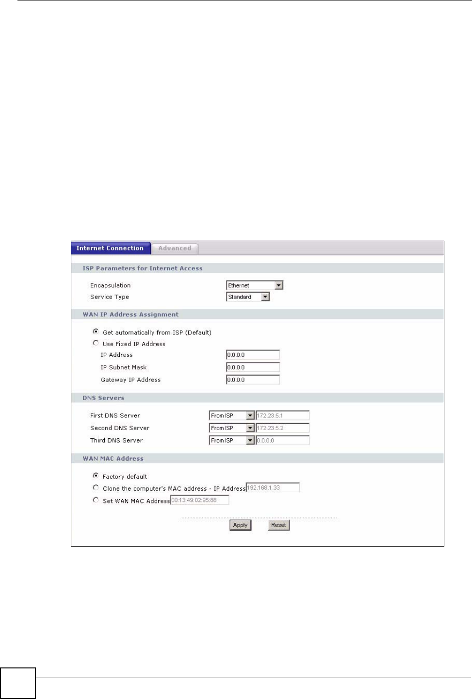
6The Confirm Save window appears. Check your settings and click Save to continue.
Chapter 6 Wireless Tutorial
NBG334W User’s Guide
92
Figure 49 Confirm Save
7Check the status of your wireless connection in the screen below. If your wireless
connection is weak or you have no connection, see the Troubleshooting section of this
User’s Guide.
Figure 50 Link Status
8If your connection is successful, open your Internet browser and enter http://
www.zyxel.com or the URL of any other web site in the address bar. If you are able to
access the web site, your wireless connection is successfully configured.

NBG334W User’s Guide 93
CHAPTER 7
WAN
This chapter describes how to configure WAN settings.
7.1 WAN Overview
See the chapter about the connection wizard for more information on the fields in the WAN
screens.
7.2 WAN MAC Address
The MAC address screen allows users to configure the WAN port's MAC address by either
using the factory default or cloning the MAC address from a computer on your LAN. Choose
Factory Default to select the factory assigned default MAC Address.
Otherwise, click Clone the computer's MAC address - IP Address and enter the IP address
of the computer on the LAN whose MAC you are cloning. Once it is successfully configured,
the address will be copied to the rom file (ZyNOS configuration file). It will not change unless
you change the setting or upload a different ROM file. It is recommended that you clone the
MAC address prior to hooking up the WAN Port.
7.3 Multicast
Traditionally, IP packets are transmitted in one of either two ways - Unicast (1 sender - 1
recipient) or Broadcast (1 sender - everybody on the network). Multicast delivers IP packets to
a group of hosts on the network - not everybody and not just 1.
IGMP (Internet Group Multicast Protocol) is a network-layer protocol used to establish
membership in a Multicast group - it is not used to carry user data. IGMP version 2 (RFC
2236) is an improvement over version 1 (RFC 1112) but IGMP version 1 is still in wide use. If
you would like to read more detailed information about interoperability between IGMP
version 2 and version 1, please see sections 4 and 5 of RFC 2236. The class D IP address is
used to identify host groups and can be in the range 224.0.0.0 to 239.255.255.255. The address
224.0.0.0 is not assigned to any group and is used by IP multicast computers. The address
224.0.0.1 is used for query messages and is assigned to the permanent group of all IP hosts
(including gateways). All hosts must join the 224.0.0.1 group in order to participate in IGMP.
The address 224.0.0.2 is assigned to the multicast routers group.
Chapter 7 WAN
NBG334W User’s Guide
94
The NBG334W supports both IGMP version 1 (IGMP-v1) and IGMP version 2 (IGMP-v2).
At start up, the NBG334W queries all directly connected networks to gather group
membership. After that, the NBG334W periodically updates this information. IP multicasting
can be enabled/disabled on the NBG334W LAN and/or WAN interfaces in the web
configurator (LAN; WA N). Select None to disable IP multicasting on these interfaces.
7.4 Internet Connection
Use this screen to change your NBG334W’s Internet access settings. Click Network > WA N .
The screen differs according to the encapsulation you choose.
7.4.1 Ethernet Encapsulation
This screen displays when you select Ethernet encapsulation.
Figure 51 Network > WAN > Internet Connection: Ethernet Encapsulation

Chapter 7 WAN
NBG334W User’s Guide 95
The following table describes the labels in this screen.
7.4.2 PPPoE Encapsulation
The NBG334W supports PPPoE (Point-to-Point Protocol over Ethernet). PPPoE is an IETF
standard (RFC 2516) specifying how a personal computer (PC) interacts with a broadband
modem (DSL, cable, wireless, etc.) connection. The PPP over Ethernet option is for a dial-
up connection using PPPoE.
Table 36 Network > WAN > Internet Connection: Ethernet Encapsulation
LABEL DESCRIPTION
Encapsulation You must choose the Ethernet option when the WAN port is used as a regular
Ethernet.
Service Type Choose from Standard, RR-Telstra (RoadRunner Telstra authentication
method), RR-Manager (Roadrunner Manager authentication method), RR-
Toshiba (Roadrunner Toshiba authentication method) or Telia Login.
The following fields do not appear with the Standard service type.
WAN IP Address Assignment
Get automatically
from ISP
Select this option If your ISP did not assign you a fixed IP address. This is the
default selection.
Use Fixed IP
Address
Select this option If the ISP assigned a fixed IP address.
IP Address Enter your WAN IP address in this field if you selected Use Fixed IP Address.
IP Subnet
Mask
Enter the IP Subnet Mask in this field.
Gateway IP
Address
Enter a Gateway IP Address (if your ISP gave you one) in this field.
DNS Servers
First DNS Server
Second DNS
Server
Third DNS Server
Select From ISP if your ISP dynamically assigns DNS server information (and the
NBG334W's WAN IP address). The field to the right displays the (read-only) DNS
server IP address that the ISP assigns.
Select User-Defined if you have the IP address of a DNS server. Enter the DNS
server's IP address in the field to the right. If you chose User-Defined, but leave
the IP address set to 0.0.0.0, User-Defined changes to None after you click
Apply. If you set a second choice to User-Defined, and enter the same IP
address, the second User-Defined changes to None after you click Apply.
Select None if you do not want to configure DNS servers. If you do not configure
a DNS server, you must know the IP address of a computer in order to access it.
WAN MAC
Address
The MAC address section allows users to configure the WAN port's MAC address
by either using the NBG334W’s MAC address, copying the MAC address from a
computer on your LAN or manually entering a MAC address.
Factory default Select Factory default to use the factory assigned default MAC Address.
Clone the
computer’s MAC
address
Select Clone the computer's MAC address - IP Address and enter the IP
address of the computer on the LAN whose MAC you are cloning. Once it is
successfully configured, the address will be copied to the rom file (ZyNOS
configuration file). It will not change unless you change the setting or upload a
different ROM file.
Set WAN MAC
Address
Select this option and enter the MAC address you want to use.
Apply Click Apply to save your changes back to the NBG334W.
Reset Click Reset to begin configuring this screen afresh.
Chapter 7 WAN
NBG334W User’s Guide
96
For the service provider, PPPoE offers an access and authentication method that works with
existing access control systems (for example Radius).
One of the benefits of PPPoE is the ability to let you access one of multiple network services,
a function known as dynamic service selection. This enables the service provider to easily
create and offer new IP services for individuals.
Operationally, PPPoE saves significant effort for both you and the ISP or carrier, as it requires
no specific configuration of the broadband modem at the customer site.
By implementing PPPoE directly on the NBG334W (rather than individual computers), the
computers on the LAN do not need PPPoE software installed, since the NBG334W does that
part of the task. Furthermore, with NAT, all of the LANs’ computers will have access.
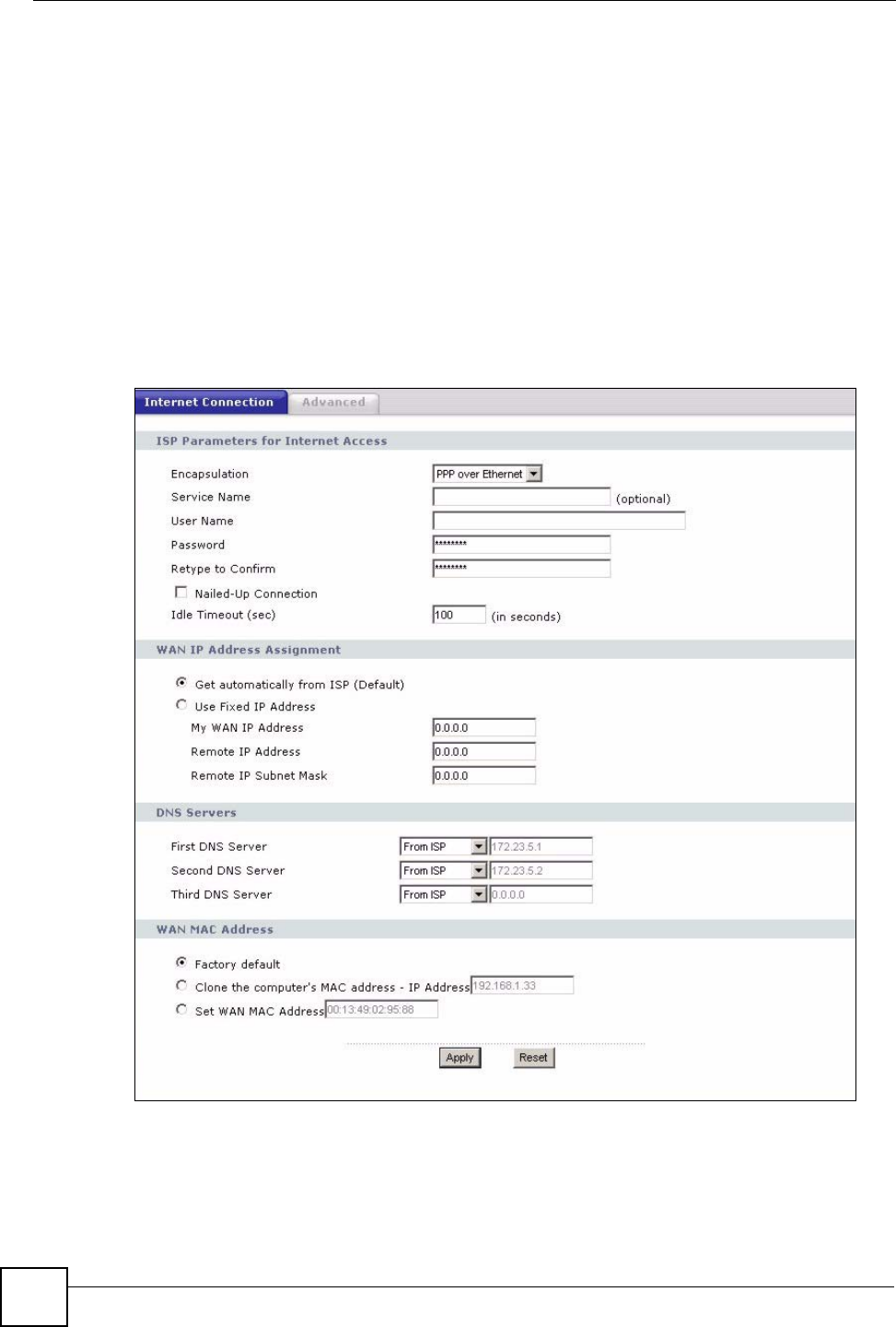
This screen displays when you select PPPoE encapsulation.
Figure 52 Network > WAN > Internet Connection: PPPoE Encapsulation

Chapter 7 WAN
NBG334W User’s Guide 97
The following table describes the labels in this screen.
Table 37 Network > WAN > Internet Connection: PPPoE Encapsulation
LABEL DESCRIPTION
ISP Parameters for Internet Access
Encapsulation The PPP over Ethernet choice is for a dial-up connection using PPPoE. The
NBG334W supports PPPoE (Point-to-Point Protocol over Ethernet). PPPoE is an
IETF Draft standard (RFC 2516) specifying how a personal computer (PC)
interacts with a broadband modem (i.e. xDSL, cable, wireless, etc.) connection.
Operationally, PPPoE saves significant effort for both the end user and ISP/carrier,
as it requires no specific configuration of the broadband modem at the customer
site. By implementing PPPoE directly on the router rather than individual
computers, the computers on the LAN do not need PPPoE software installed, since
the router does that part of the task. Further, with NAT, all of the LAN's computers
will have access.
Service Name Type the PPPoE service name provided to you. PPPoE uses a service name to
identify and reach the PPPoE server.
User Name Type the user name given to you by your ISP.
Password Type the password associated with the user name above.
Retype to
Confirm
Type your password again to make sure that you have entered is correctly.
Nailed-Up
Connection
Select Nailed-Up Connection if you do not want the connection to time out.
Idle Timeout This value specifies the time in seconds that elapses before the router
automatically disconnects from the PPPoE server.
WAN IP Address Assignment
Get automatically
from ISP
Select this option If your ISP did not assign you a fixed IP address. This is the
default selection.
Use Fixed IP
Address
Select this option If the ISP assigned a fixed IP address.
My WAN IP
Address
Enter your WAN IP address in this field if you selected Use Fixed IP Address.
Remote IP
Address
Enter the remote IP address (if your ISP gave you one) in this field.
Remote IP
Subnet Mask
Enter the remote IP subnet mask in this field.
DNS Servers
First DNS Server
Second DNS
Server
Third DNS Server
Select From ISP if your ISP dynamically assigns DNS server information (and the
NBG334W's WAN IP address). The field to the right displays the (read-only) DNS
server IP address that the ISP assigns.
Select User-Defined if you have the IP address of a DNS server. Enter the DNS
server's IP address in the field to the right. If you chose User-Defined, but leave
the IP address set to 0.0.0.0, User-Defined changes to None after you click
Apply. If you set a second choice to User-Defined, and enter the same IP
address, the second User-Defined changes to None after you click Apply.
Select None if you do not want to configure DNS servers. If you do not configure a
DNS server, you must know the IP address of a computer in order to access it.
WAN MAC
Address
The MAC address section allows users to configure the WAN port's MAC address
by using the NBG334W’s MAC address, copying the MAC address from a
computer on your LAN or manually entering a MAC address.
Factory default Select Factory default to use the factory assigned default MAC Address.

Chapter 7 WAN
NBG334W User’s Guide
98
7.4.3 PPTP Encapsulation
Point-to-Point Tunneling Protocol (PPTP) is a network protocol that enables secure transfer of
data from a remote client to a private server, creating a Virtual Private Network (VPN) using
TCP/IP-based networks.
PPTP supports on-demand, multi-protocol and virtual private networking over public
networks, such as the Internet.
This screen displays when you select PPTP encapsulation.
Clone the
computer’s MAC
address
Select Clone the computer's MAC address - IP Address and enter the IP
address of the computer on the LAN whose MAC you are cloning. Once it is
successfully configured, the address will be copied to the rom file (ZyNOS
configuration file). It will not change unless you change the setting or upload a
different ROM file.
Set WAN MAC
Address
Select this option and enter the MAC address you want to use.
Apply Click Apply to save your changes back to the NBG334W.
Reset Click Reset to begin configuring this screen afresh.
Table 37 Network > WAN > Internet Connection: PPPoE Encapsulation
LABEL DESCRIPTION
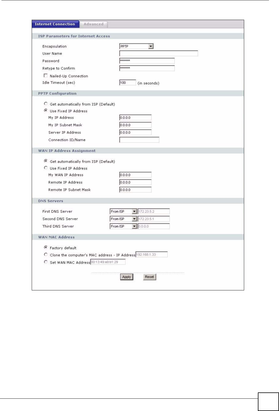
Chapter 7 WAN
NBG334W User’s Guide 99
Figure 53 Network > WAN > Internet Connection: PPTP Encapsulation