ZyXEL Communications NBG334W Wireless Firewall Router User Manual NBG334W User s Guide
ZyXEL Communications Corporation Wireless Firewall Router NBG334W User s Guide
Contents
- 1. Users Manual Part 1
- 2. Users Manual Part 2
- 3. Users Manual Part 3
- 4. Users Manual Part 4
Users Manual Part 3

Chapter 7 WAN
NBG334W User’s Guide
100
The following table describes the labels in this screen.
Table 38 Network > WAN > Internet Connection: PPTP Encapsulation
LABEL DESCRIPTION
ISP Parameters for Internet Access
Encapsulation Point-to-Point Tunneling Protocol (PPTP) is a network protocol that enables
secure transfer of data from a remote client to a private server, creating a
Virtual Private Network (VPN) using TCP/IP-based networks. PPTP supports
on-demand, multi-protocol, and virtual private networking over public
networks, such as the Internet. The NBG334W supports only one PPTP
server connection at any given time.
To configure a PPTP client, you must configure the User Name and
Password fields for a PPP connection and the PPTP parameters for a PPTP
connection.
User Name Type the user name given to you by your ISP.
Password Type the password associated with the User Name above.
Retype to Confirm Type your password again to make sure that you have entered is correctly.
Nailed-up Connection Select Nailed-Up Connection if you do not want the connection to time out.
Idle Timeout This value specifies the time in seconds that elapses before the NBG334W
automatically disconnects from the PPTP server.
PPTP Configuration
Get automatically from
ISP
Select this option If your ISP did not assign you a fixed IP address. This is the
default selection.
Use Fixed IP Address Select this option If the ISP assigned a fixed IP address.
My IP Address Type the (static) IP address assigned to you by your ISP.
My IP Subnet
Mask
Your NBG334W will automatically calculate the subnet mask based on the IP
address that you assign. Unless you are implementing subnetting, use the
subnet mask computed by the NBG334W.
Server IP Address Type the IP address of the PPTP server.
Connection ID/
Name
Type your identification name for the PPTP server.
WAN IP Address Assignment
Get automatically from
ISP
Select this option If your ISP did not assign you a fixed IP address. This is the
default selection.
Use Fixed IP Address Select this option If the ISP assigned a fixed IP address.
My WAN IP
Address
Enter your WAN IP address in this field if you selected Use Fixed IP
Address.
Remote IP
Address
Enter the remote IP address (if your ISP gave you one) in this field.
Remote IP Subnet
Mask
Enter the remote IP subnet mask in this field.
DNS Servers
Chapter 7 WAN
NBG334W User’s Guide 101
7.5 Advanced WAN Screen
To change your NBG334W’s advanced WAN settings, click Network > WAN > Advanced.
The screen appears as shown.
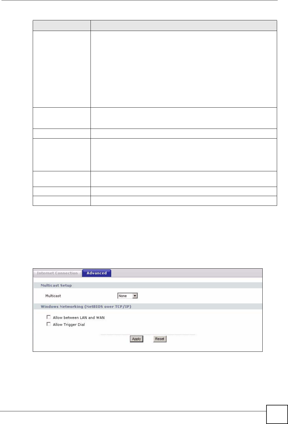
Figure 54 Network > WAN > Advanced
First DNS Server
Second DNS Server
Third DNS Server
Select From ISP if your ISP dynamically assigns DNS server information (and
the NBG334W's WAN IP address). The field to the right displays the (read-
only) DNS server IP address that the ISP assigns.
Select User-Defined if you have the IP address of a DNS server. Enter the
DNS server's IP address in the field to the right. If you chose User-Defined,
but leave the IP address set to 0.0.0.0, User-Defined changes to None after
you click Apply. If you set a second choice to User-Defined, and enter the
same IP address, the second User-Defined changes to None after you click
Apply.
Select None if you do not want to configure DNS servers. If you do not
configure a DNS server, you must know the IP address of a computer in order
to access it.
WAN MAC Address The MAC address section allows users to configure the WAN port's MAC
address by either using the NBG334W’s MAC address, copying the MAC
address from a computer on your LAN or manually entering a MAC address.
Factory default Select Factory default to use the factory assigned default MAC Address.
Clone the computer’s
MAC address
Select Clone the computer's MAC address - IP Address and enter the IP
address of the computer on the LAN whose MAC you are cloning. Once it is
successfully configured, the address will be copied to the rom file (ZyNOS
configuration file). It will not change unless you change the setting or upload a
different ROM file.
Set WAN MAC
Address
Select this option and enter the MAC address you want to use.
Apply Click Apply to save your changes back to the NBG334W.
Reset Click Reset to begin configuring this screen afresh.
Table 38 Network > WAN > Internet Connection: PPTP Encapsulation
LABEL DESCRIPTION
Chapter 7 WAN
NBG334W User’s Guide
102
The following table describes the labels in this screen.
Table 39 WAN > Advanced
LABEL DESCRIPTION
Multicast Setup
Multicast Select IGMP V-1, IGMP V-2 or None. IGMP (Internet Group Multicast
Protocol) is a network-layer protocol used to establish membership in a
Multicast group - it is not used to carry user data. IGMP version 2 (RFC 2236)
is an improvement over version 1 (RFC 1112) but IGMP version 1 is still in
wide use. If you would like to read more detailed information about
interoperability between IGMP version 2 and version 1, please see sections 4
and 5 of RFC 2236.
Windows Networking (NetBIOS over TCP/IP): NetBIOS (Network Basic Input/Output System) are TCP
or UDP broadcast packets that enable a computer to connect to and communicate with a LAN. For
some dial-up services such as PPPoE or PPTP, NetBIOS packets cause unwanted calls. However it
may sometimes be necessary to allow NetBIOS packets to pass through to the WAN in order to find a
computer on the WAN.
Allow between LAN
and WAN
Select this check box to forward NetBIOS packets from the LAN to the WAN
and from the WAN to the LAN. If your firewall is enabled with the default
policy set to block WAN to LAN traffic, you also need to enable the default
WAN to LAN firewall rule that forwards NetBIOS traffic.
Clear this check box to block all NetBIOS packets going from the LAN to the
WAN and from the WAN to the LAN.
Allow Trigger Dial Select this option to allow NetBIOS packets to initiate calls.
Apply Click Apply to save your changes back to the NBG334W.
Reset Click Reset to begin configuring this screen afresh.

NBG334W User’s Guide 103
CHAPTER 8
LAN
This chapter describes how to configure LAN settings.
8.1 LAN Overview
A Local Area Network (LAN) is a shared communication system to which many computers
are attached. A LAN is a computer network limited to the immediate area, usually the same
building or floor of a building. The LAN screens can help you configure a LAN DHCP server,
manage IP addresses, and partition your physical network into logical networks.
8.1.1 IP Pool Setup
The NBG334W is pre-configured with a pool of 32 IP addresses starting from 192.168.1.33 to
192.168.1.64. This configuration leaves 31 IP addresses (excluding the NBG334W itself) in
the lower range (192.168.1.2 to 192.168.1.32) for other server computers, for instance, servers
for mail, FTP, TFTP, web, etc., that you may have.
8.1.2 System DNS Servers
Refer to the IP address and subnet mask section in the Connection Wizard chapter.
8.2 LAN TCP/IP
The NBG334W has built-in DHCP server capability that assigns IP addresses and DNS
servers to systems that support DHCP client capability.
8.2.1 Factory LAN Defaults
The LAN parameters of the NBG334W are preset in the factory with the following values:
• IP address of 192.168.1.1 with subnet mask of 255.255.255.0 (24 bits)
• DHCP server enabled with 32 client IP addresses starting from 192.168.1.33.
These parameters should work for the majority of installations. If your ISP gives you explicit
DNS server address(es), read the embedded web configurator help regarding what fields need
to be configured.

Chapter 8 LAN
NBG334W User’s Guide
104
8.2.2 IP Address and Subnet Mask
Refer to the IP address and subnet mask section in the Connection Wizard chapter for this
information.
8.2.3 Multicast
Traditionally, IP packets are transmitted in one of either two ways - Unicast (1 sender - 1
recipient) or Broadcast (1 sender - everybody on the network). Multicast delivers IP packets to
a group of hosts on the network - not everybody and not just 1.
IGMP (Internet Group Management Protocol) is a network-layer protocol used to establish
membership in a Multicast group - it is not used to carry user data. IGMP version 2 (RFC
2236) is an improvement over version 1 (RFC 1112) but IGMP version 1 is still in wide use. If
you would like to read more detailed information about interoperability between IGMP
version 2 and version 1, please see sections 4 and 5 of RFC 2236. The class D IP address is
used to identify host groups and can be in the range 224.0.0.0 to 239.255.255.255. The address
224.0.0.0 is not assigned to any group and is used by IP multicast computers. The address
224.0.0.1 is used for query messages and is assigned to the permanent group of all IP hosts
(including gateways). All hosts must join the 224.0.0.1 group in order to participate in IGMP.
The address 224.0.0.2 is assigned to the multicast routers group.
The NBG334W supports both IGMP version 1 (IGMP-v1) and IGMP version 2 (IGMP-v2).
At start up, the NBG334W queries all directly connected networks to gather group
membership. After that, the NBG334W periodically updates this information. IP multicasting
can be enabled/disabled on the NBG334W LAN and/or WAN interfaces in the web
configurator (LAN; WA N ). Select None to disable IP multicasting on these interfaces.
8.2.4 Any IP
Traditionally, you must set the IP addresses and the subnet masks of a computer and the
NBG334W to be in the same subnet to allow the computer to access the Internet (through the
NBG334W). In cases where your computer is required to use a static IP address in another
network, you may need to manually configure the network settings of the computer every time
you want to access the Internet via the NBG334W.
With the Any IP feature and NAT enabled, the NBG334W allows a computer to access the
Internet without changing the network settings (such as IP address and subnet mask) of the
computer, when the IP addresses of the computer and the NBG334W are not in the same
subnet. Whether a computer is set to use a dynamic or static (fixed) IP address, you can simply
connect the computer to the NBG334W and access the Internet.
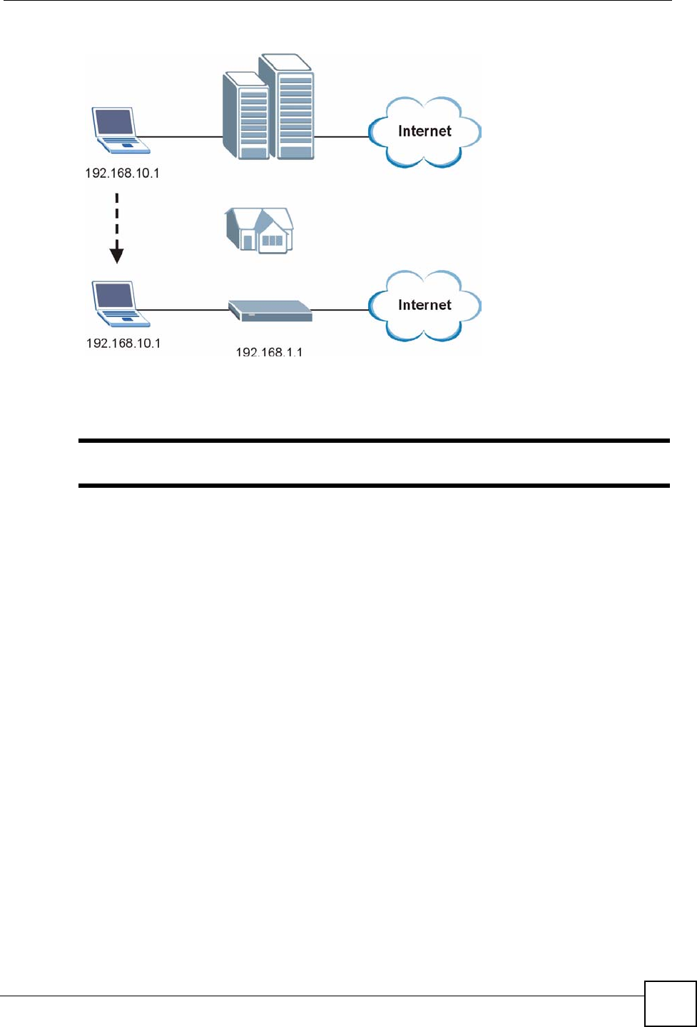
The following figure depicts a scenario where a computer is set to use a static private IP
address in the corporate environment. In a residential house where a NBG334W is installed,
you can still use the computer to access the Internet without changing the network settings,
even when the IP addresses of the computer and the NBG334W are not in the same subnet.
Chapter 8 LAN
NBG334W User’s Guide 105
Figure 55 Any IP Example
The Any IP feature does not apply to a computer using either a dynamic IP address or a static
IP address that is in the same subnet as the NBG334W’s IP address.
"You must enable NAT to use the Any IP feature on the NBG334W.
Address Resolution Protocol (ARP) is a protocol for mapping an Internet Protocol address (IP
address) to a physical machine address, also known as a Media Access Control or MAC
address, on the local area network. IP routing table is defined on IP Ethernet devices (the
NBG334W) to decide which hop to use, to help forward data along to its specified destination.
The following lists out the steps taken, when a computer tries to access the Internet for the first
time through the NBG334W.
1When a computer (which is in a different subnet) first attempts to access the Internet, it
sends packets to its default gateway (which is not the NBG334W) by looking at the
MAC address in its ARP table.
2When the computer cannot locate the default gateway, an ARP request is broadcast on
the LAN.
3The NBG334W receives the ARP request and replies to the computer with its own MAC
address.
4The computer updates the MAC address for the default gateway to the ARP table. Once
the ARP table is updated, the computer is able to access the Internet through the
NBG334W.
5When the NBG334W receives packets from the computer, it creates an entry in the IP
routing table so it can properly forward packets intended for the computer.
After all the routing information is updated, the computer can access the NBG334W and the
Internet as if it is in the same subnet as the NBG334W.
Chapter 8 LAN
NBG334W User’s Guide
106
8.3 LAN IP Screen
Use this screen to change your basic LAN settings. Click Network > LAN.
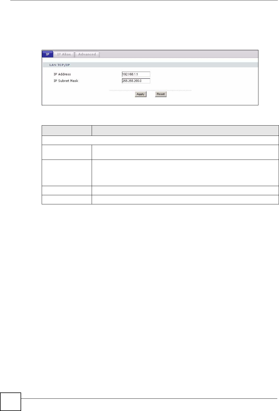
Figure 56 Network > LAN > IP
The following table describes the labels in this screen.
8.4 LAN IP Alias
IP alias allows you to partition a physical network into different logical networks over the
same Ethernet interface. The NBG334W supports three logical LAN interfaces via its single
physical Ethernet interface with the NBG334W itself as the gateway for each LAN network.
To change your NBG334W’s IP alias settings, click Network > LAN > IP Alias. The screen
appears as shown.
Table 40 Network > LAN > IP
LABEL DESCRIPTION
LAN TCP/IP
IP Address Type the IP address of your NBG334W in dotted decimal notation 192.168.1.1
(factory default).
IP Subnet Mask The subnet mask specifies the network number portion of an IP address. Your
NBG334W will automatically calculate the subnet mask based on the IP address
that you assign. Unless you are implementing subnetting, use the subnet mask
computed by the NBG334W.
Apply Click Apply to save your changes back to the NBG334W.
Reset Click Reset to begin configuring this screen afresh.
Chapter 8 LAN
NBG334W User’s Guide 107
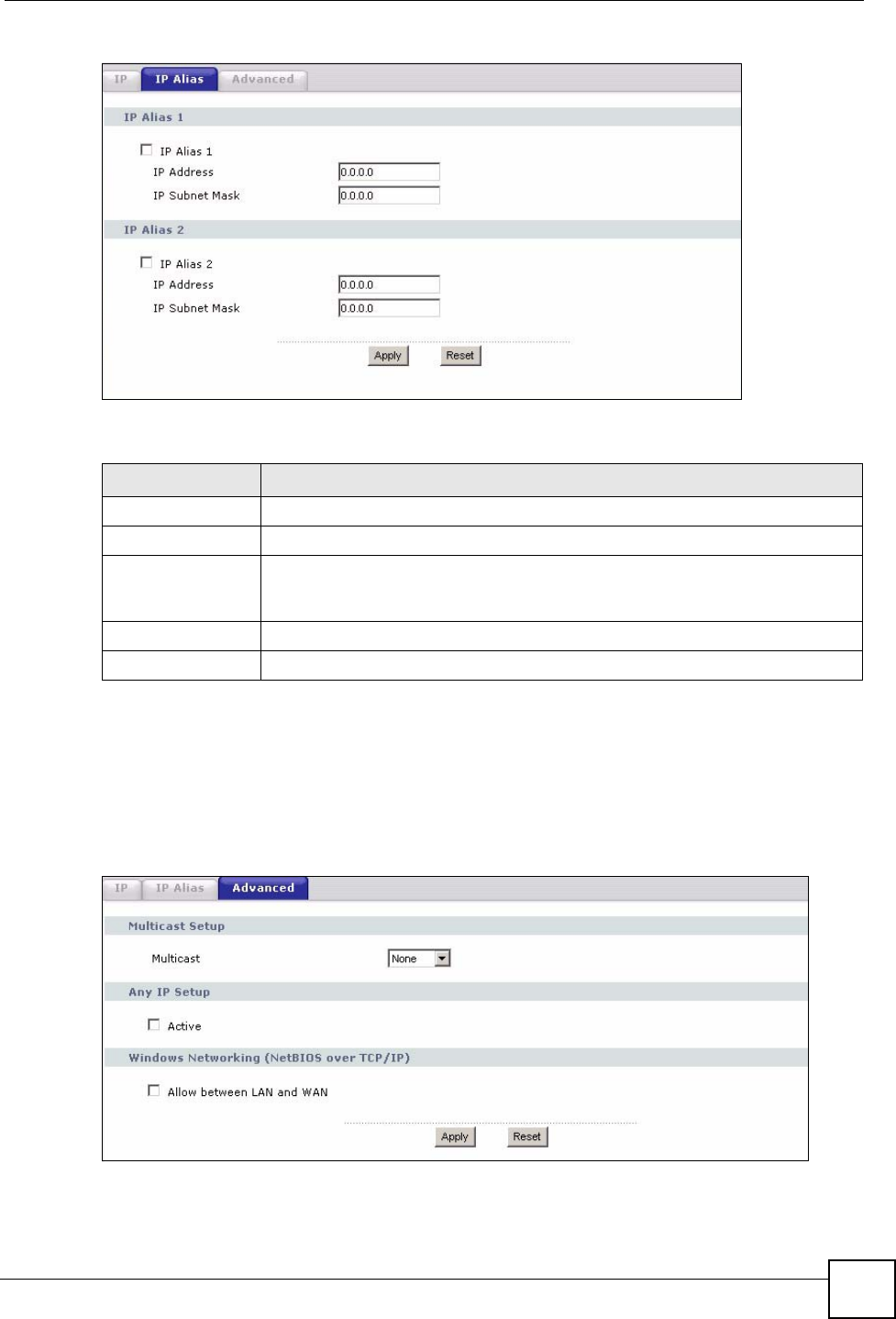
Figure 57 Network > LAN > IP Alias
The following table describes the labels in this screen.
8.5 Advanced LAN Screen
To change your NBG334W’s advanced IP settings, click Network > LAN > Advanced. The
screen appears as shown.
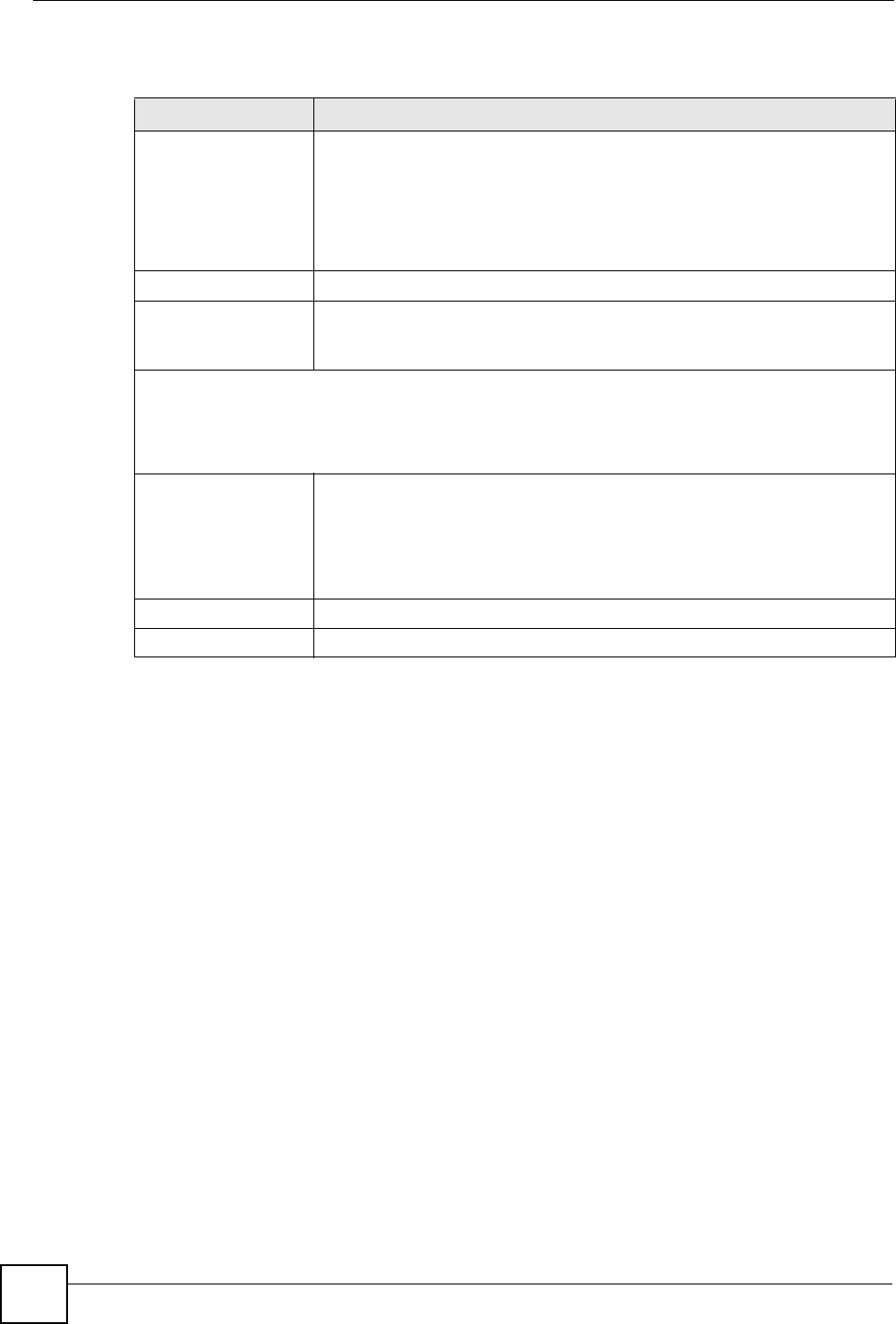
Figure 58 Network > LAN > Advanced
Table 41 Network > LAN > IP Alias
LABEL DESCRIPTION
IP Alias 1,2 Select the check box to configure another LAN network for the NBG334W.
IP Address Enter the IP address of your NBG334W in dotted decimal notation.
IP Subnet Mask Your NBG334W will automatically calculate the subnet mask based on the IP
address that you assign. Unless you are implementing subnetting, use the
subnet mask computed by the NBG334W.
Apply Click Apply to save your changes back to the NBG334W.
Reset Click Reset to begin configuring this screen afresh.
Chapter 8 LAN
NBG334W User’s Guide
108
The following table describes the labels in this screen.
Table 42 Network > LAN > Advanced
LABEL DESCRIPTION
Multicast Select IGMP V-1 or IGMP V-2 or None. IGMP (Internet Group Multicast
Protocol) is a network-layer protocol used to establish membership in a
Multicast group - it is not used to carry user data. IGMP version 2 (RFC 2236)
is an improvement over version 1 (RFC 1112) but IGMP version 1 is still in
wide use. If you would like to read more detailed information about
interoperability between IGMP version 2 and version 1, please see sections 4
and 5 of RFC 2236.
Any IP Setup
Active Select this if you want to let computers on different subnets use the
NBG334W.
Windows Networking (NetBIOS over TCP/IP): NetBIOS (Network Basic Input/Output System) are TCP
or UDP broadcast packets that enable a computer to connect to and communicate with a LAN. For
some dial-up services such as PPPoE or PPTP, NetBIOS packets cause unwanted calls. However it
may sometimes be necessary to allow NetBIOS packets to pass through to the WAN in order to find a
computer on the WAN.
Allow between LAN
and WAN
Select this check box to forward NetBIOS packets from the LAN to the WAN
and from the WAN to the LAN. If your firewall is enabled with the default policy
set to block WAN to LAN traffic, you also need to enable the default WAN to
LAN firewall rule that forwards NetBIOS traffic.
Clear this check box to block all NetBIOS packets going from the LAN to the
WAN and from the WAN to the LAN.
Apply Click Apply to save your changes back to the NBG334W.
Reset Click Reset to begin configuring this screen afresh.

NBG334W User’s Guide 109
CHAPTER 9
DHCP
9.1 DHCP
DHCP (Dynamic Host Configuration Protocol, RFC 2131 and RFC 2132) allows individual
clients to obtain TCP/IP configuration at start-up from a server. You can configure the
NBG334W as a DHCP server or disable it. When configured as a server, the NBG334W
provides the TCP/IP configuration for the clients. If DHCP service is disabled, you must have
another DHCP server on your LAN, or else the computer must be manually configured.
9.2 DHCP Server General Screen
Click Network > DHCP Server. The following screen displays.
Figure 59 Network > DHCP Server > General
The following table describes the labels in this screen.
Table 43 Network > DHCP Server > General
LABEL DESCRIPTION
Enable DHCP Server DHCP (Dynamic Host Configuration Protocol, RFC 2131 and RFC 2132)
allows individual clients (computers) to obtain TCP/IP configuration at startup
from a server. Leave the Enable DHCP Server check box selected unless
your ISP instructs you to do otherwise. Clear it to disable the NBG334W
acting as a DHCP server. When configured as a server, the NBG334W
provides TCP/IP configuration for the clients. If not, DHCP service is disabled
and you must have another DHCP server on your LAN, or else the computers
must be manually configured. When set as a server, fill in the following four
fields.
IP Pool Starting
Address
This field specifies the first of the contiguous addresses in the IP address
pool.
Pool Size This field specifies the size, or count of the IP address pool.
Apply Click Apply to save your changes back to the NBG334W.
Reset Click Reset to begin configuring this screen afresh.
Chapter 9 DHCP
NBG334W User’s Guide
110
9.3 DHCP Server Advanced Screen
This screen allows you to assign IP addresses on the LAN to specific individual computers
based on their MAC addresses. You can also use this screen to configure the DNS server
information that the NBG334W sends to the DHCP clients.
Every Ethernet device has a unique MAC (Media Access Control) address. The MAC address
is assigned at the factory and consists of six pairs of hexadecimal characters, for example,
00:A0:C5:00:00:02.
To change your NBG334W’s static DHCP settings, click Network > DHCP Server >
Advanced. The following screen displays.
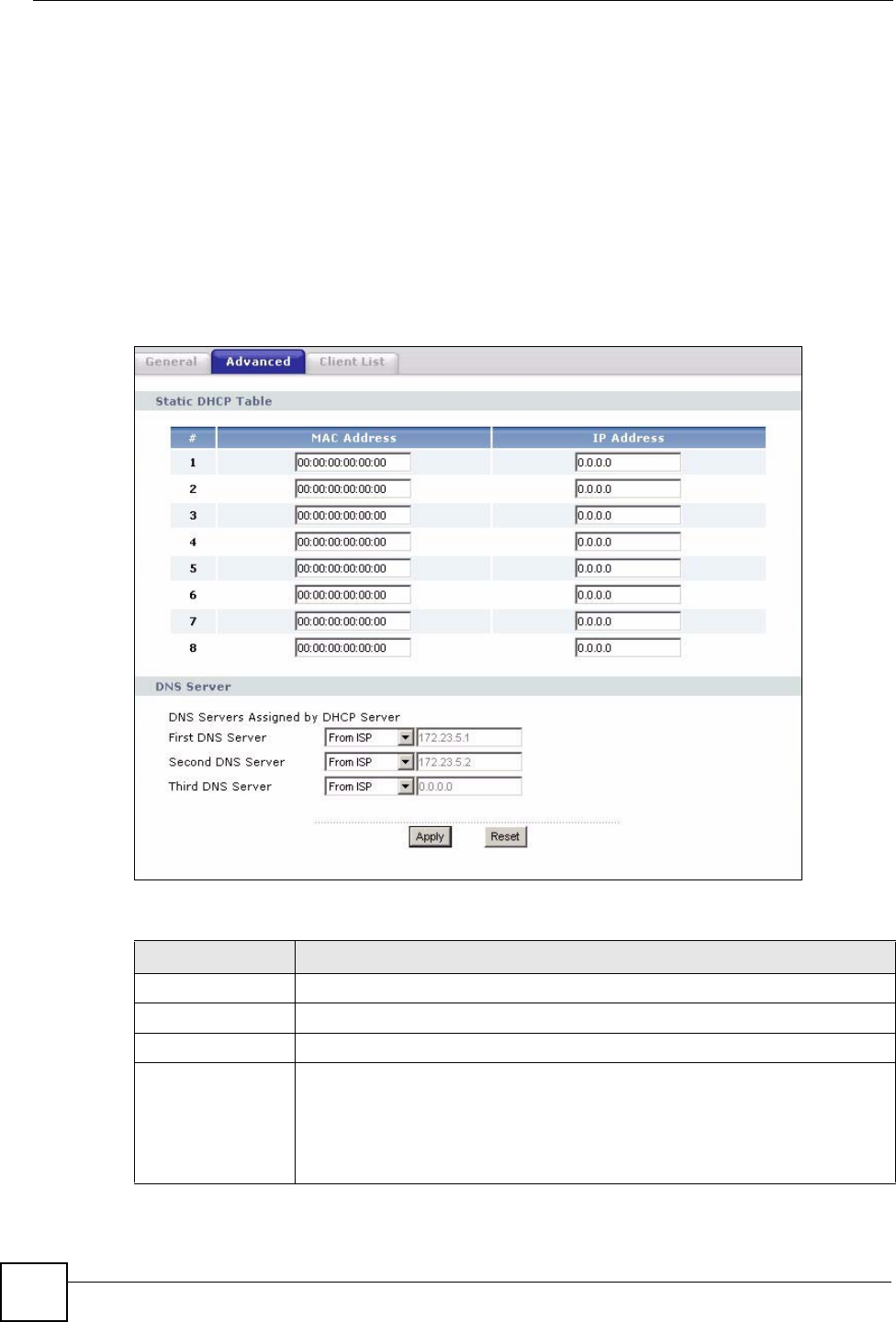
Figure 60 Network > DHCP Server > Advanced
The following table describes the labels in this screen.
Table 44 Network > DHCP Server > Advanced
LABEL DESCRIPTION
# This is the index number of the static IP table entry (row).
MAC Address Type the MAC address (with colons) of a computer on your LAN.
IP Address Type the LAN IP address of a computer on your LAN.
DNS Servers
Assigned by DHCP
Server
The NBG334W passes a DNS (Domain Name System) server IP address (in the
order you specify here) to the DHCP clients. The NBG334W only passes this
information to the LAN DHCP clients when you select the Enable DHCP Server
check box. When you clear the Enable DHCP Server check box, DHCP service
is disabled and you must have another DHCP sever on your LAN, or else the
computers must have their DNS server addresses manually configured.
Chapter 9 DHCP
NBG334W User’s Guide 111
9.4 Client List Screen
The DHCP table shows current DHCP client information (including IP Address, Host Name
and MAC Address) of all network clients using the NBG334W’s DHCP server.
Configure this screen to always assign an IP address to a MAC address (and host name). Click
Network > DHCP Server > Client List.
"You can also view a read-only client list by clicking the DHCP Table
(Details...) hyperlink in the Status screen.
The following screen displays.
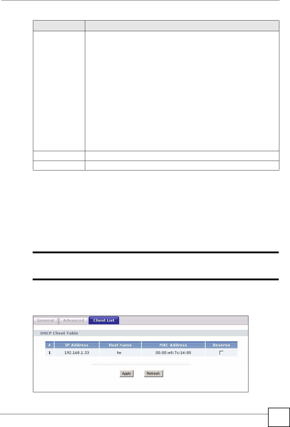
Figure 61 Network > DHCP Server > Client List
First DNS Server
Second DNS
Server
Third DNS Server
Select From ISP if your ISP dynamically assigns DNS server information (and
the NBG334W's WAN IP address). The field to the right displays the (read-only)
DNS server IP address that the ISP assigns.
Select User-Defined if you have the IP address of a DNS server. Enter the DNS
server's IP address in the field to the right. If you chose User-Defined, but leave
the IP address set to 0.0.0.0, User-Defined changes to None after you click
Apply. If you set a second choice to User-Defined, and enter the same IP
address, the second User-Defined changes to None after you click Apply.
Select DNS Relay to have the NBG334W act as a DNS proxy. The NBG334W's
LAN IP address displays in the field to the right (read-only). The NBG334W tells
the DHCP clients on the LAN that the NBG334W itself is the DNS server. When
a computer on the LAN sends a DNS query to the NBG334W, the NBG334W
forwards the query to the NBG334W's system DNS server (configured in the
WAN > Internet Connection screen) and relays the response back to the
computer. You can only select DNS Relay for one of the three servers; if you
select DNS Relay for a second or third DNS server, that choice changes to
None after you click Apply.
Select None if you do not want to configure DNS servers. If you do not configure
a DNS server, you must know the IP address of a computer in order to access it.
Apply Click Apply to save your changes back to the NBG334W.
Reset Click Reset to begin configuring this screen afresh.
Table 44 Network > DHCP Server > Advanced
LABEL DESCRIPTION

Chapter 9 DHCP
NBG334W User’s Guide
112
The following table describes the labels in this screen.
Table 45 Network > DHCP Server > Client List
LABEL DESCRIPTION
# This is the index number of the host computer.
IP Address This field displays the IP address relative to the # field listed above.
Host Name This field displays the computer host name.
MAC Address The MAC (Media Access Control) or Ethernet address on a LAN (Local Area
Network) is unique to your computer (six pairs of hexadecimal notation).
A network interface card such as an Ethernet adapter has a hardwired
address that is assigned at the factory. This address follows an industry
standard that ensures no other adapter has a similar address.
Reserve Select this check box to have the NBG334W always assign this IP address to
this MAC address (and host name). After you click Apply, the MAC address
and IP address also display in the Advanced screen (where you can edit
them).
Apply Click Apply to save your settings.
Refresh Click Refresh to reload the DHCP table.

NBG334W User’s Guide 113
CHAPTER 10
Network Address Translation
(NAT)
This chapter discusses how to configure NAT on the NBG334W.
10.1 NAT Overview
NAT (Network Address Translation - NAT, RFC 1631) is the translation of the IP address of a
host in a packet. For example, the source address of an outgoing packet, used within one
network is changed to a different IP address known within another network.
10.2 Using NAT
"You must create a firewall rule in addition to setting up NAT, to allow traffic
from the WAN to be forwarded through the NBG334W.
10.2.1 Port Forwarding: Services and Port Numbers
A port forwarding set is a list of inside (behind NAT on the LAN) servers, for example, web or
FTP, that you can make accessible to the outside world even though NAT makes your whole
inside network appear as a single machine to the outside world.
Use the Application screen to forward incoming service requests to the server(s) on your local
network. You may enter a single port number or a range of port numbers to be forwarded, and
the local IP address of the desired server. The port number identifies a service; for example,
web service is on port 80 and FTP on port 21. In some cases, such as for unknown services or
where one server can support more than one service (for example both FTP and web service),
it might be better to specify a range of port numbers.
In addition to the servers for specified services, NAT supports a default server. A service
request that does not have a server explicitly designated for it is forwarded to the default
server. If the default is not defined, the service request is simply discarded.
Chapter 10 Network Address Translation (NAT)
NBG334W User’s Guide
114
"Many residential broadband ISP accounts do not allow you to run any server
processes (such as a Web or FTP server) from your location. Your ISP may
periodically check for servers and may suspend your account if it discovers
any active services at your location. If you are unsure, refer to your ISP.
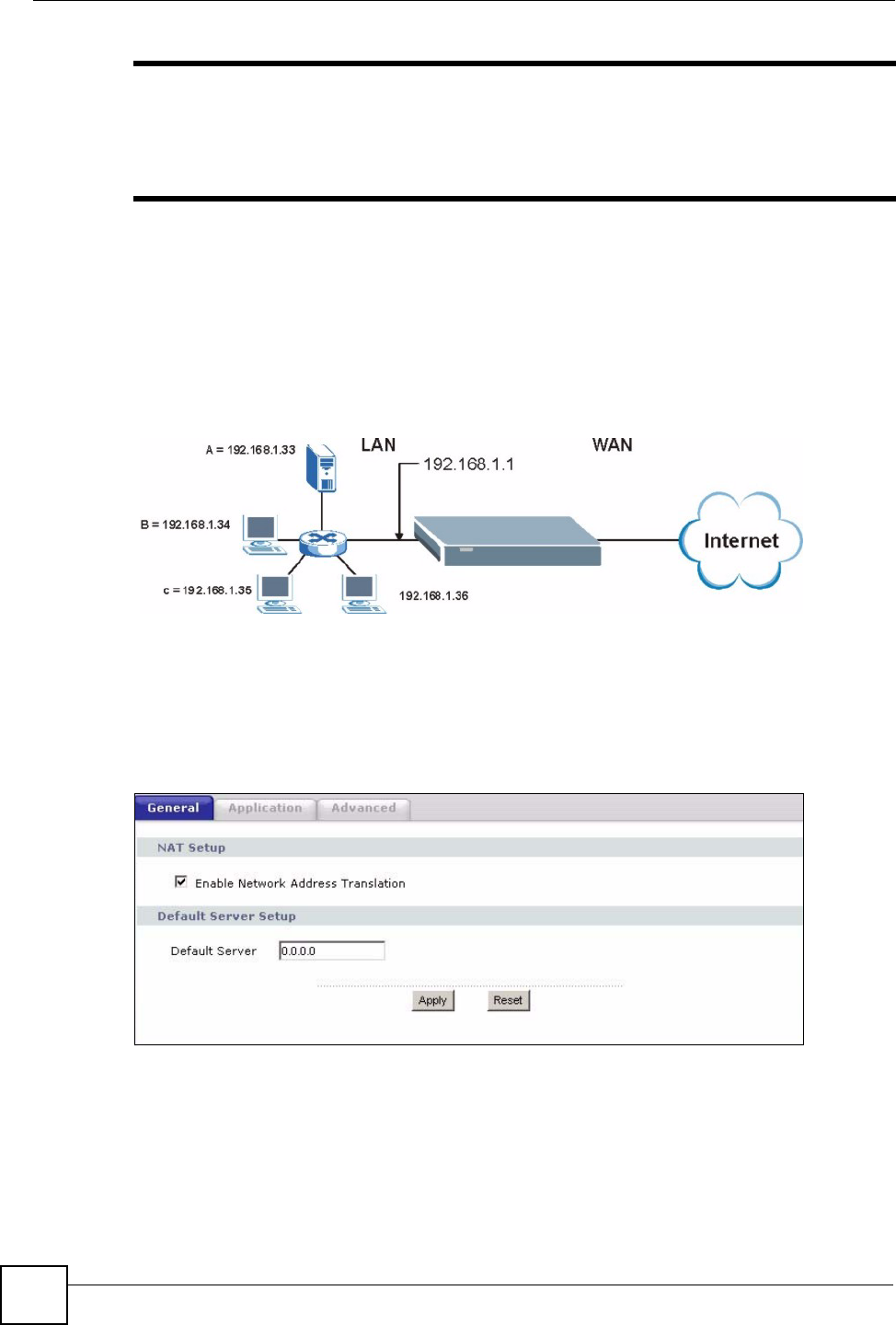
10.2.2 Configuring Servers Behind Port Forwarding Example
Let's say you want to assign ports 21-25 to one FTP, Telnet and SMTP server (A in the
example), port 80 to another (B in the example) and assign a default server IP address of
192.168.1.35 to a third (C in the example). You assign the LAN IP addresses and the ISP
assigns the WAN IP address. The NAT network appears as a single host on the Internet
Figure 62 Multiple Servers Behind NAT Example
10.3 General NAT Screen
Click Network > NAT to open the General screen.
Figure 63 Network > NAT > General

Chapter 10 Network Address Translation (NAT)
NBG334W User’s Guide 115
The following table describes the labels in this screen.
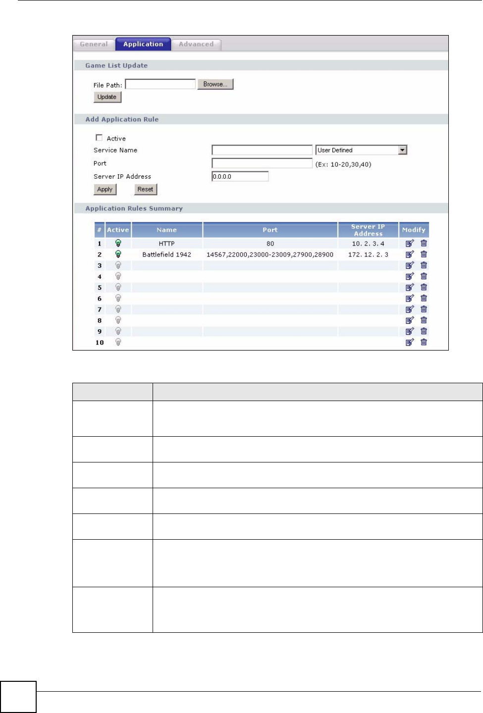
10.4 NAT Application Screen
Port forwarding allows you to define the local servers to which the incoming services will be
forwarded. To change your NBG334W’s port forwarding settings, click Network > NAT >
Application. The screen appears as shown.
"If you do not assign a Default Server IP address in the NAT > General
screen, the NBG334W discards all packets received for ports that are not
specified in this screen or remote management.
Refer to Appendix F on page 259 for port numbers commonly used for particular services.
Table 46 Network > NAT > General
LABEL DESCRIPTION
Enable Network
Address
Translation
Network Address Translation (NAT) allows the translation of an Internet protocol
address used within one network (for example a private IP address used in a local
network) to a different IP address known within another network (for example a
public IP address used on the Internet).
Select the check box to enable NAT.
Default Server
Setup
Default Server In addition to the servers for specified services, NAT supports a default server. A
default server receives packets from ports that are not specified in the Application
screen.
If you do not assign a Default Server IP address, the NBG334W discards all
packets received for ports that are not specified in the Application screen or
remote management.
Apply Click Apply to save your changes back to the NBG334W.
Reset Click Reset to begin configuring this screen afresh.
Chapter 10 Network Address Translation (NAT)
NBG334W User’s Guide
116
Figure 64 Network > NAT > Application
The following table describes the labels in this screen.
Table 47 NAT Application
LABEL DESCRIPTION
Game List Update A game list includes the pre-defined service name(s) and port number(s). You can
edit and upload it to the NBG334W to replace the existing entries in the second
field next to Service Name.
File Path Type in the location of the file you want to upload in this field or click Browse... to
find it.
Browse... Click Browse... to find the.txt file you want to upload. Remember that you must
decompress compressed (.zip) files before you can upload them.
Update Click Update to begin the upload process. This process may take up to two
minutes.
Add Application
Rule
Active Select the check box to enable this rule and the requested service can be
forwarded to the host with a specified internal IP address.
Clear the checkbox to disallow forwarding of these ports to an inside server
without having to delete the entry.
Service Name Type a name (of up to 31 printable characters) to identify this rule in the first field
next to Service Name. Otherwise, select a predefined service in the second field
next to Service Name. The predefined service name and port number(s) will
display in the Service Name and Port fields.

Chapter 10 Network Address Translation (NAT)
NBG334W User’s Guide 117
10.4.1 Game List Example
Here is an example game list text file. The index number, service name and associated port(s)
are specified by semi-colons (no spaces). Use the name=xxx (where xxx is the service name)
to create a new service. Port range can be separated with a hyphen (-) (no spaces). Multiple
(non-consecutive) ports can be separated by commas.
Port Type a port number(s) to be forwarded.
To specify a range of ports, enter a hyphen (-) between the first port and the last
port, such as 10-20.
To specify two or more non-consecutive port numbers, separate them by a comma
without spaces, such as 123,567.
Server IP Address Type the inside IP address of the server that receives packets from the port(s)
specified in the Port field.
Apply Click Apply to save your changes to the Application Rules Summary table.
Reset Click Reset to not save and return your new changes in the Service Name and
Port fields to the previous one.
Application Rules
Summary
#This is the number of an individual port forwarding server entry.
Active This icon is turned on when the rule is enabled.
Name This field displays a name to identify this rule.
Port This field displays the port number(s).
Server IP Address This field displays the inside IP address of the server.
Modify Click the Edit icon to display and modify an existing rule setting in the fields under
Add Application Rule.
Click the Remove icon to delete a rule.
Table 47 NAT Application (continued)
LABEL DESCRIPTION

Chapter 10 Network Address Translation (NAT)
NBG334W User’s Guide
118
Figure 65 Game List Example
10.5 Trigger Port Forwarding
Some services use a dedicated range of ports on the client side and a dedicated range of ports
on the server side. With regular port forwarding you set a forwarding port in NAT to forward a
service (coming in from the server on the WAN) to the IP address of a computer on the client
side (LAN). The problem is that port forwarding only forwards a service to a single LAN IP
address. In order to use the same service on a different LAN computer, you have to manually
replace the LAN computer's IP address in the forwarding port with another LAN computer's IP
address.
Trigger port forwarding solves this problem by allowing computers on the LAN to
dynamically take turns using the service. The NBG334W records the IP address of a LAN
computer that sends traffic to the WAN to request a service with a specific port number and
protocol (a "trigger" port). When the NBG334W's WAN port receives a response with a
specific port number and protocol ("incoming" port), the NBG334W forwards the traffic to the
LAN IP address of the computer that sent the request. After that computer’s connection for
that service closes, another computer on the LAN can use the service in the same manner. This
way you do not need to configure a new IP address each time you want a different LAN
computer to use the application.
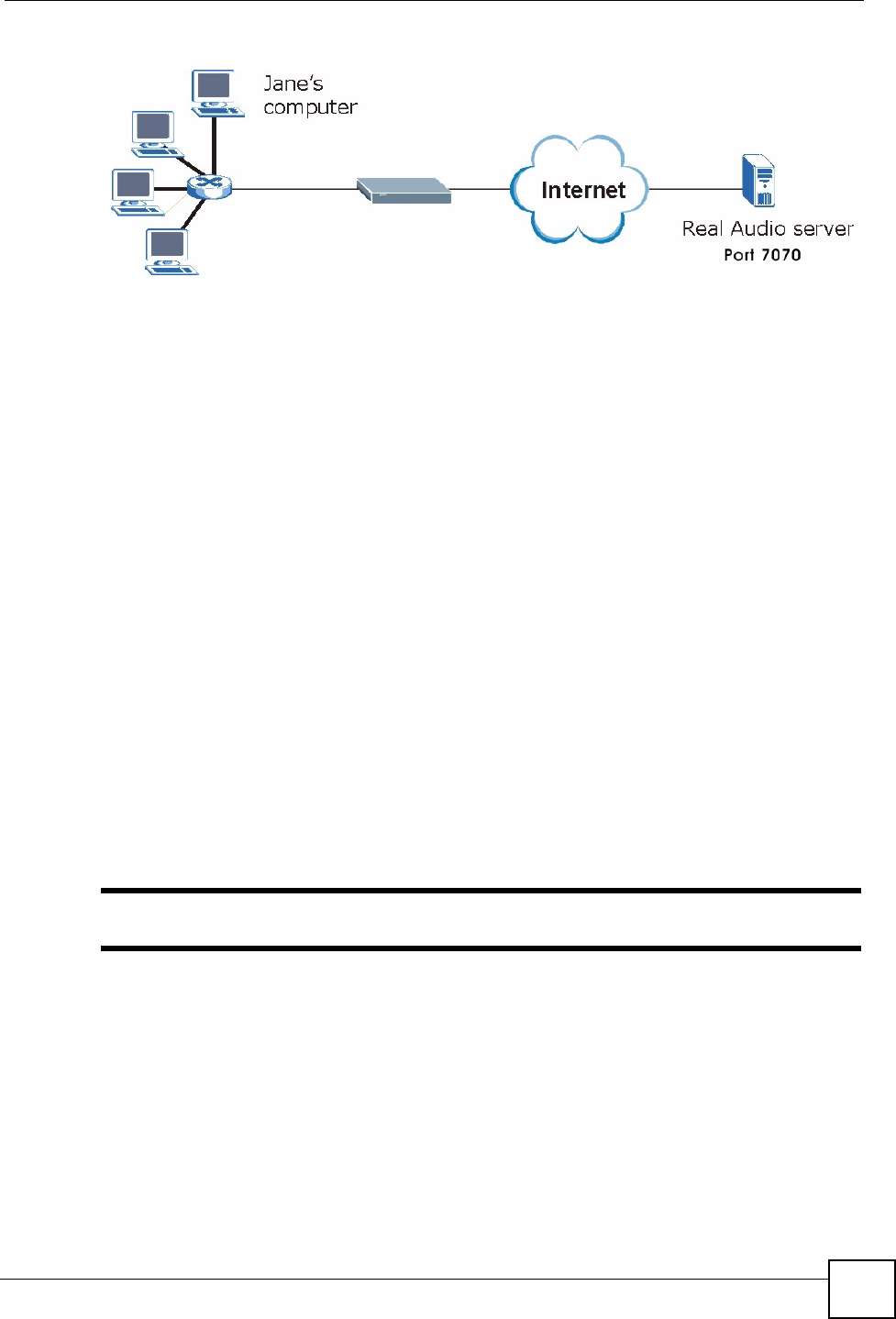
10.5.1 Trigger Port Forwarding Example
The following is an example of trigger port forwarding.
version=1
1;name=Battlefield 1942;port=14567,22000,23000-23009,27900,28900
2;name=Call of Duty;port=28960
3;name=Civilization IV;port=2056
4;name=Diablo I and II;port=6112-6119,4000
5;name=Doom 3;port=27666
6;name=F.E.A.R;port=27888
7;name=Final Fantasy XI;port=25,80,110,443,50000-65535
8;name=Guild Wars;port=6112,80
9;name=Half Life;port=6003,7002,27005,27010,27011,27015
10;name=Jedi Knight III: Jedi Academy;port=28060-28062,28070-28081
11;name=Need for Speed: Hot Pursuit 2;port=1230,8511-
8512,27900,28900,61200-61230
12;name=Neverwinter Nights;port=5120-5300,6500,27900,28900
13;name=Quake 2;port=27910
14;name=Quake 3;port=27660,27960
15;name=Rainbow Six 3: Raven Shield;port=7777-7787,8777-8787
16;name=Serious Sam II;port=25600-25605
17;name=Silent Hunter III;port=17997-18003
18;name=Soldier of Fortune II;port=20100-20112
19;name=Starcraft;port=6112-6119,4000
20;name=Star Trek: Elite Force II;port=29250,29256
21;name=SWAT 4;port=10480-10483
22;name=Warcraft II and III;port=6112-6119,4000
23;name=World of Warcraft;port=3724
Chapter 10 Network Address Translation (NAT)
NBG334W User’s Guide 119
Figure 66 Trigger Port Forwarding Process: Example
1Jane requests a file from the Real Audio server (port 7070).
2Port 7070 is a “trigger” port and causes the NBG334W to record Jane’s computer IP
address. The NBG334W associates Jane's computer IP address with the "incoming" port
range of 6970-7170.
3The Real Audio server responds using a port number ranging between 6970-7170.
4The NBG334W forwards the traffic to Jane’s computer IP address.
5Only Jane can connect to the Real Audio server until the connection is closed or times
out. The NBG334W times out in three minutes with UDP (User Datagram Protocol), or
two hours with TCP/IP (Transfer Control Protocol/Internet Protocol).
10.5.2 Two Points To Remember About Trigger Ports
1Trigger events only happen on data that is going coming from inside the NBG334W and
going to the outside.
2If an application needs a continuous data stream, that port (range) will be tied up so that
another computer on the LAN can’t trigger it.
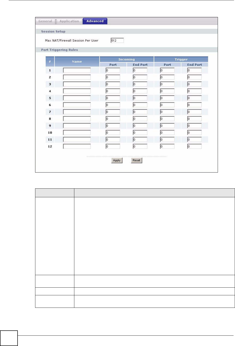
10.6 NAT Advanced Screen
To change your NBG334W’s trigger port settings, click Network > NAT > Advanced. The
screen appears as shown.
"Only one LAN computer can use a trigger port (range) at a time.
Chapter 10 Network Address Translation (NAT)
NBG334W User’s Guide
120
Figure 67 Network > NAT > Advanced
The following table describes the labels in this screen.
Table 48 Network > NAT > Advanced
LABEL DESCRIPTION
Max NAT/Firewall
Session Per User
Type a number ranging from 1 to 2048 to limit the number of NAT/firewall sessions
that a host can create.
When computers use peer to peer applications, such as file sharing
applications, they may use a large number of NAT sessions. If you do not
limit the number of NAT sessions a single client can establish, this can result in all
of the available NAT sessions being used. In this case, no additional NAT
sessions can be established, and users may not be able to access the Internet.
Each NAT session establishes a corresponding firewall session. Use this field to
limit the number of NAT/firewall sessions each client computer can establish
through the NBG334W.
If your network has a small number of clients using peer to peer applications, you
can raise this number to ensure that their performance is not degraded by the
number of NAT sessions they can establish. If your network has a large number of
users using peer to peer applications, you can lower this number to ensure no
single client is using all of the available NAT sessions.
Port Triggering
Rules
#This is the rule index number (read-only).
Name Type a unique name (up to 15 characters) for identification purposes. All
characters are permitted - including spaces.

Chapter 10 Network Address Translation (NAT)
NBG334W User’s Guide 121
Incoming Incoming is a port (or a range of ports) that a server on the WAN uses when it
sends out a particular service. The NBG334W forwards the traffic with this port (or
range of ports) to the client computer on the LAN that requested the service.
Start Port Type a port number or the starting port number in a range of port numbers.
End Port Type a port number or the ending port number in a range of port numbers.
Trigger The trigger port is a port (or a range of ports) that causes (or triggers) the
NBG334W to record the IP address of the LAN computer that sent the traffic to a
server on the WAN.
Start Port Type a port number or the starting port number in a range of port numbers.
End Port Type a port number or the ending port number in a range of port numbers.
Apply Click Apply to save your changes back to the NBG334W.
Reset Click Reset to begin configuring this screen afresh.
Table 48 Network > NAT > Advanced
LABEL DESCRIPTION

Chapter 10 Network Address Translation (NAT)
NBG334W User’s Guide
122

NBG334W User’s Guide 123
CHAPTER 11
Dynamic DNS
11.1 Dynamic DNS Introduction
Dynamic DNS allows you to update your current dynamic IP address with one or many
dynamic DNS services so that anyone can contact you (in NetMeeting, CU-SeeMe, etc.). You
can also access your FTP server or Web site on your own computer using a domain name (for
instance myhost.dhs.org, where myhost is a name of your choice) that will never change
instead of using an IP address that changes each time you reconnect. Your friends or relatives
will always be able to call you even if they don't know your IP address.
First of all, you need to have registered a dynamic DNS account with www.dyndns.org. This is
for people with a dynamic IP from their ISP or DHCP server that would still like to have a
domain name. The Dynamic DNS service provider will give you a password or key.
11.1.1 DynDNS Wildcard
Enabling the wildcard feature for your host causes *.yourhost.dyndns.org to be aliased to the
same IP address as yourhost.dyndns.org. This feature is useful if you want to be able to use,
for example, www.yourhost.dyndns.org and still reach your hostname.
"If you have a private WAN IP address, then you cannot use Dynamic DNS.
11.2 Dynamic DNS Screen
To change your NBG334W’s DDNS, click Network > DDNS. The screen appears as shown.
Chapter 11 Dynamic DNS
NBG334W User’s Guide
124
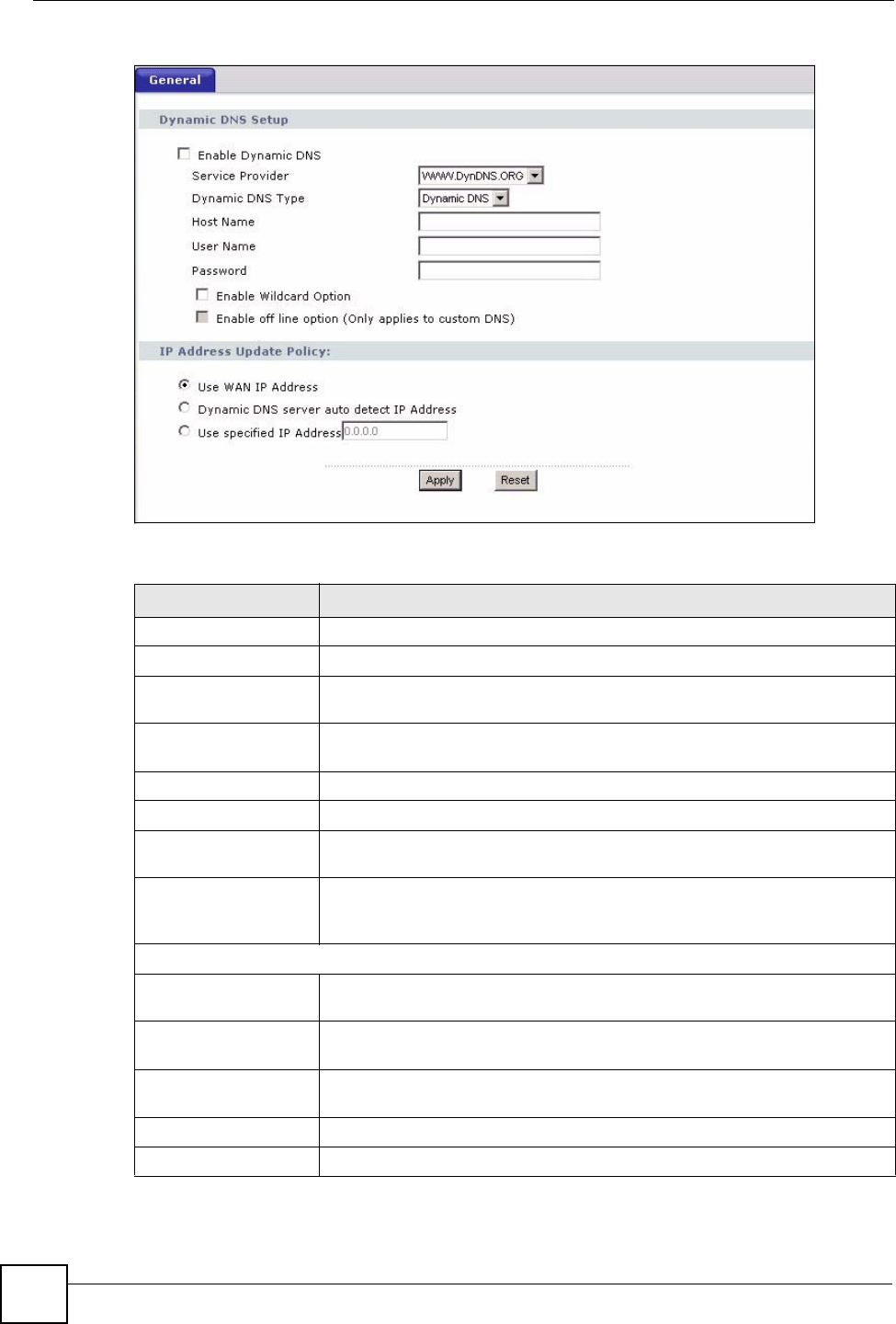
Figure 68 Dynamic DNS
The following table describes the labels in this screen.
Table 49 Dynamic DNS
LABEL DESCRIPTION
Enable Dynamic DNS Select this check box to use dynamic DNS.
Service Provider Select the name of your Dynamic DNS service provider.
Dynamic DNS Type Select the type of service that you are registered for from your Dynamic DNS
service provider.
Host Name Enter a host names in the field provided. You can specify up to two host
names in the field separated by a comma (",").
User Name Enter your user name.
Password Enter the password assigned to you.
Enable Wildcard
Option
Select the check box to enable DynDNS Wildcard.
Enable off line option This option is available when CustomDNS is selected in the DDNS Type
field. Check with your Dynamic DNS service provider to have traffic
redirected to a URL (that you can specify) while you are off line.
IP Address Update Policy:
Use WAN IP Address Select this option to update the IP address of the host name(s) to the WAN IP
address.
Dynamic DNS server
auto detect IP Address
Select this option to update the IP address of the host name(s) automatically
by the DDNS server. It is recommended that you select this option.
Use specified IP
Address
Type the IP address of the host name(s). Use this if you have a static IP
address.
Apply Click Apply to save your changes back to the NBG334W.
Reset Click Reset to begin configuring this screen afresh.

125
PART III
Security
Firewall (127)
Content Filtering (133)

126

NBG334W User’s Guide 127
CHAPTER 12
Firewall
This chapter gives some background information on firewalls and explains how to get started
with the NBG334W’s firewall.
12.1 Introduction to ZyXEL’s Firewall
12.1.1 What is a Firewall?
Originally, the term “firewall” referred to a construction technique designed to prevent the
spread of fire from one room to another. The networking term "firewall" is a system or group
of systems that enforces an access-control policy between two networks. It may also be
defined as a mechanism used to protect a trusted network from a network that is not trusted. Of
course, firewalls cannot solve every security problem. A firewall is one of the mechanisms
used to establish a network security perimeter in support of a network security policy. It
should never be the only mechanism or method employed. For a firewall to guard effectively,
you must design and deploy it appropriately. This requires integrating the firewall into a broad
information-security policy. In addition, specific policies must be implemented within the
firewall itself.
12.1.2 Stateful Inspection Firewall
Stateful inspection firewalls restrict access by screening data packets against defined access
rules. They make access control decisions based on IP address and protocol. They also
"inspect" the session data to assure the integrity of the connection and to adapt to dynamic
protocols. These firewalls generally provide the best speed and transparency; however, they
may lack the granular application level access control or caching that some proxies support.
Firewalls, of one type or another, have become an integral part of standard security solutions
for enterprises.
12.1.3 About the NBG334W Firewall
The NBG334W firewall is a stateful inspection firewall and is designed to protect against
Denial of Service attacks when activated (click the General tab under Firewall and then click
the Enable Firewall check box). The NBG334W's purpose is to allow a private Local Area
Network (LAN) to be securely connected to the Internet. The NBG334W can be used to
prevent theft, destruction and modification of data, as well as log events, which may be
important to the security of your network.

Chapter 12 Firewall
NBG334W User’s Guide
128
The NBG334W is installed between the LAN and a broadband modem connecting to the
Internet. This allows it to act as a secure gateway for all data passing between the Internet and
the LAN.
The NBG334W has one Ethernet WAN port and four Ethernet LAN ports, which are used to
physically separate the network into two areas.The WAN (Wide Area Network) port attaches
to the broadband (cable or DSL) modem to the Internet.
The LAN (Local Area Network) port attaches to a network of computers, which needs security
from the outside world. These computers will have access to Internet services such as e-mail,
FTP and the World Wide Web. However, "inbound access" is not allowed (by default) unless
the remote host is authorized to use a specific service.
12.1.4 Guidelines For Enhancing Security With Your Firewall
1Change the default password via web configurator.
2Think about access control before you connect to the network in any way, including
attaching a modem to the port.
3Limit who can access your router.
4Don't enable any local service (such as SNMP or NTP) that you don't use. Any enabled
service could present a potential security risk. A determined hacker might be able to find
creative ways to misuse the enabled services to access the firewall or the network.
5For local services that are enabled, protect against misuse. Protect by configuring the
services to communicate only with specific peers, and protect by configuring rules to
block packets for the services at specific interfaces.
6Protect against IP spoofing by making sure the firewall is active.
7Keep the firewall in a secured (locked) room.
12.2 Triangle Routes
If an alternate gateway on the LAN has an IP address in the same subnet as the NBG334W’s
LAN IP address, return traffic may not go through the NBG334W. This is called an
asymmetrical or “triangle” route. This causes the NBG334W to reset the connection, as the
connection has not been acknowledged.
You can have the NBG334W permit the use of asymmetrical route topology on the network
(not reset the connection).
Allowing asymmetrical routes may let traffic from the WAN go directly to the LAN without
passing through the NBG334W. A better solution is to use IP alias to put the NBG334W and
the backup gateway on separate subnets.
12.2.1 Triangle Routes and IP Alias
You can use IP alias instead of allowing triangle routes. IP Alias allow you to partition your
network into logical sections over the same interface.
By putting your LAN and Gateway A in different subnets, all returning network traffic must
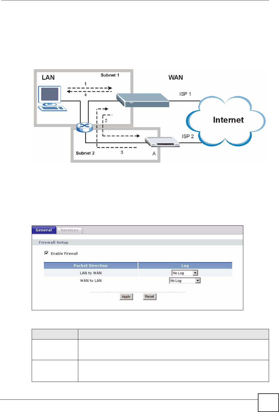
pass through the NBG334W to your LAN. The following steps describe such a scenario.
Chapter 12 Firewall
NBG334W User’s Guide 129
1A computer on the LAN initiates a connection by sending a SYN packet to a receiving
server on the WAN.
2The NBG334W reroutes the packet to Gateway A, which is in Subnet 2.
3The reply from the WAN goes to the NBG334W.
4The NBG334W then sends it to the computer on the LAN in Subnet 1.
Figure 69 Using IP Alias to Solve the Triangle Route Problem
12.3 General Firewall Screen
Click Security > Firewall to open the General screen. Use this screen to enable or disable the
NBG334W’s firewall, and set up firewall logs.
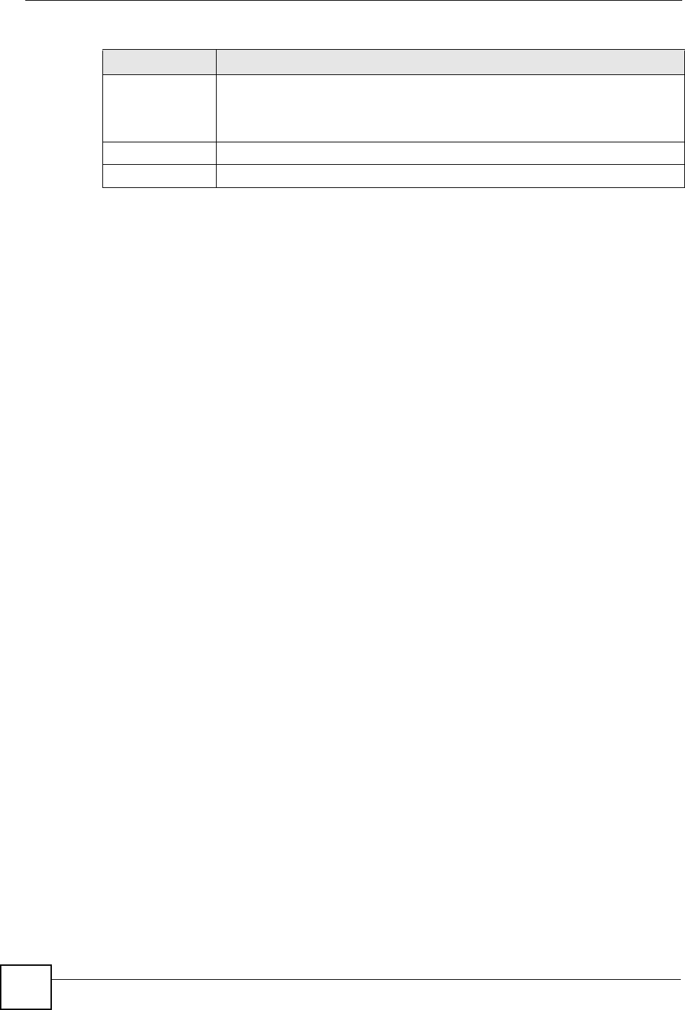
Figure 70 Security > Firewall > General l
The following table describes the labels in this screen.
Table 50 Security > Firewall > General
LABEL DESCRIPTION
Enable Firewall Select this check box to activate the firewall. The NBG334W performs access
control and protects against Denial of Service (DoS) attacks when the firewall is
activated.
Packet Direction This is the direction of travel of packets.
Firewall rules are grouped based on the direction of travel of packets to which they
apply.
Chapter 12 Firewall
NBG334W User’s Guide
130
12.4 Services Screen
Click Security > Firewall > Services. The screen appears as shown next.
If an outside user attempts to probe an unsupported port on your NBG334W, an ICMP
response packet is automatically returned. This allows the outside user to know the NBG334W
exists. Use this screen to prevent the ICMP response packet from being sent. This keeps
outsiders from discovering your NBG334W when unsupported ports are probed.
You can also use this screen to enable service blocking, enter/delete/modify the services you
want to block and the date/time you want to block them.
Log Select whether to create a log for packets that are traveling in the selected
direction when the packets are blocked or forwarded.
To log packets related to firewall rules, make sure that Access Control under Log
is selected in the Logs > Log Settings screen.
Apply Click Apply to save the settings.
Reset Click Reset to start configuring this screen again.
Table 50 Security > Firewall > General
LABEL DESCRIPTION
Chapter 12 Firewall
NBG334W User’s Guide 131
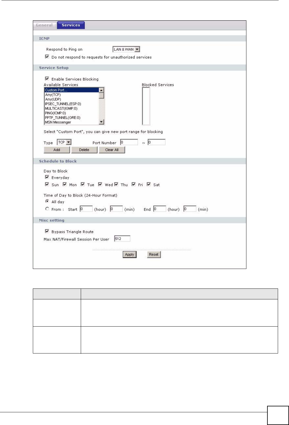
Figure 71 Security > Firewall > Services
The following table describes the labels in this screen.
Table 51 Security > Firewall > Services
LABEL DESCRIPTION
ICMP Internet Control Message Protocol is a message control and error-reporting
protocol between a host server and a gateway to the Internet. ICMP uses Internet
Protocol (IP) datagrams, but the messages are processed by the TCP/IP software
and directly apparent to the application user.
Respond to Ping
on
The NBG334W will not respond to any incoming Ping requests when Disable is
selected. Select LAN to reply to incoming LAN Ping requests. Select WAN to reply
to incoming WAN Ping requests. Otherwise select LAN & WAN to reply to both
incoming LAN and WAN Ping requests.

Chapter 12 Firewall
NBG334W User’s Guide
132
Do not respond to
requests for
unauthorized
services
Select this option to prevent hackers from finding the NBG334W by probing for
unused ports. If you select this option, the NBG334W will not respond to port
request(s) for unused ports, thus leaving the unused ports and the NBG334W
unseen. By default this option is not selected and the NBG334W will reply with an
ICMP Port Unreachable packet for a port probe on its unused UDP ports, and a
TCP Reset packet for a port probe on its unused TCP ports.
Note that the probing packets must first traverse the NBG334W's firewall
mechanism before reaching this anti-probing mechanism. Therefore if the firewall
mechanism blocks a probing packet, the NBG334W reacts based on the firewall
policy, which by default, is to send a TCP reset packet for a blocked TCP packet.
You can use the command "sys firewall tcprst rst [on|off]" to change this policy.
When the firewall mechanism blocks a UDP packet, it drops the packet without
sending a response packet.
Service Setup
Enable Services
Blocking
Select this check box to enable this feature.
Available
Services
This is a list of pre-defined services (ports) you may prohibit your LAN computers
from using. Select the port you want to block using the drop-down list and click
Add to add the port to the Blocked Services field.
Blocked Services This is a list of services (ports) that will be inaccessible to computers on your LAN
once you enable service blocking.
Custom Port A custom port is a service that is not available in the pre-defined Available
Services list and you must define using the next two fields.
Type Choose the IP port (TCP or UDP) that defines your customized port from the drop
down list box.
Port Number Enter the port number range that defines the service. For example, if you want to
define the Gnutella service, then select TCP type and enter a port range from
6345 to 6349.
Add Select a service from the Available Services drop-down list and then click Add to
add a service to the Blocked Services
Delete Select a service from the Blocked Services list and then click Delete to remove
this service from the list.
Clear All Click Clear All to empty the Blocked Services.
Schedule to Block
Day to Block: Select a check box to configure which days of the week (or everyday) you want
service blocking to be active.
Time of Day to
Block (24-Hour
Format)
Select the time of day you want service blocking to take effect. Configure blocking
to take effect all day by selecting All Day. You can also configure specific times by
selecting From and entering the start time in the Start (hour) and Start (min)
fields and the end time in the End (hour) and End (min) fields. Enter times in 24-
hour format, for example, "3:00pm" should be entered as "15:00".
Misc setting
Bypass Triangle
Route
Select this check box to have the NBG334W firewall ignore the use of triangle
route topology on the network.
Max NAT/Firewall
Session Per User
Type a number ranging from 1 to 2048 to limit the number of NAT/firewall sessions
that a host can create.
Apply Click Apply to save the settings.
Reset Click Reset to start configuring this screen again.
Table 51 Security > Firewall > Services
LABEL DESCRIPTION

NBG334W User’s Guide 133
CHAPTER 13
Content Filtering
This chapter provides a brief overview of content filtering using the embedded web GUI.
13.1 Introduction to Content Filtering
Internet content filtering allows you to create and enforce Internet access policies tailored to
your needs. Content filtering is the ability to block certain web features or specific URL
keywords.
13.2 Restrict Web Features
The NBG334W can block web features such as ActiveX controls, Java applets, cookies and
disable web proxies.
13.3 Days and Times
The NBG334W also allows you to define time periods and days during which the NBG334W
performs content filtering.
13.4 Filter Screen
Click Security > Content Filter to open the Filter screen.
Chapter 13 Content Filtering
NBG334W User’s Guide
134
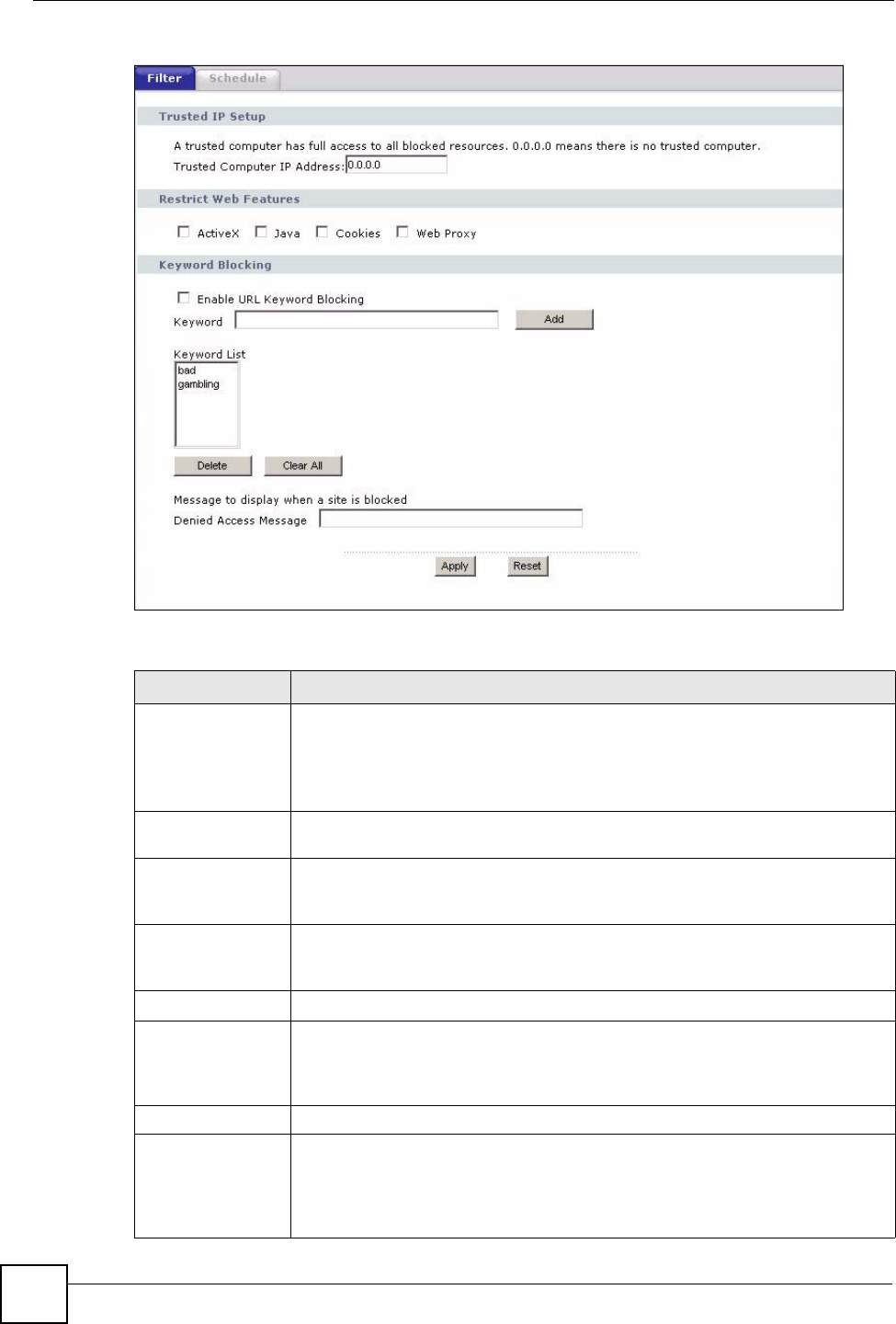
Figure 72 Security > Content Filter > Filter
The following table describes the labels in this screen.
Table 52 Security > Content Filter > Filter
LABEL DESCRIPTION
Trusted Computer
IP Address
To enable this feature, type an IP address of any one of the computers in your
network that you want to have as a trusted computer. This allows the trusted
computer to have full access to all features that are configured to be blocked by
content filtering.
Leave this field blank to have no trusted computers.
Restrict Web
Features
Select the box(es) to restrict a feature. When you download a page containing a
restricted feature, that part of the web page will appear blank or grayed out.
ActiveX A tool for building dynamic and active Web pages and distributed object
applications. When you visit an ActiveX Web site, ActiveX controls are
downloaded to your browser, where they remain in case you visit the site again.
Java A programming language and development environment for building
downloadable Web components or Internet and intranet business applications of
all kinds.
Cookies Used by Web servers to track usage and provide service based on ID.
Web Proxy A server that acts as an intermediary between a user and the Internet to provide
security, administrative control, and caching service. When a proxy server is
located on the WAN it is possible for LAN users to circumvent content filtering by
pointing to this proxy server.
Keyword Blocking
Enable URL
Keyword Blocking
The NBG334W can block Web sites with URLs that contain certain keywords in
the domain name or IP address. For example, if the keyword "bad" was enabled,
all sites containing this keyword in the domain name or IP address will be
blocked, e.g., URL http://www.website.com/bad.html would be blocked. Select
this check box to enable this feature.
Chapter 13 Content Filtering
NBG334W User’s Guide 135
13.5 Schedule
Use this screen to set the day(s) and time you want the NBG334W to use content filtering.
Click Security > Content Filter > Schedule. The following screen displays.
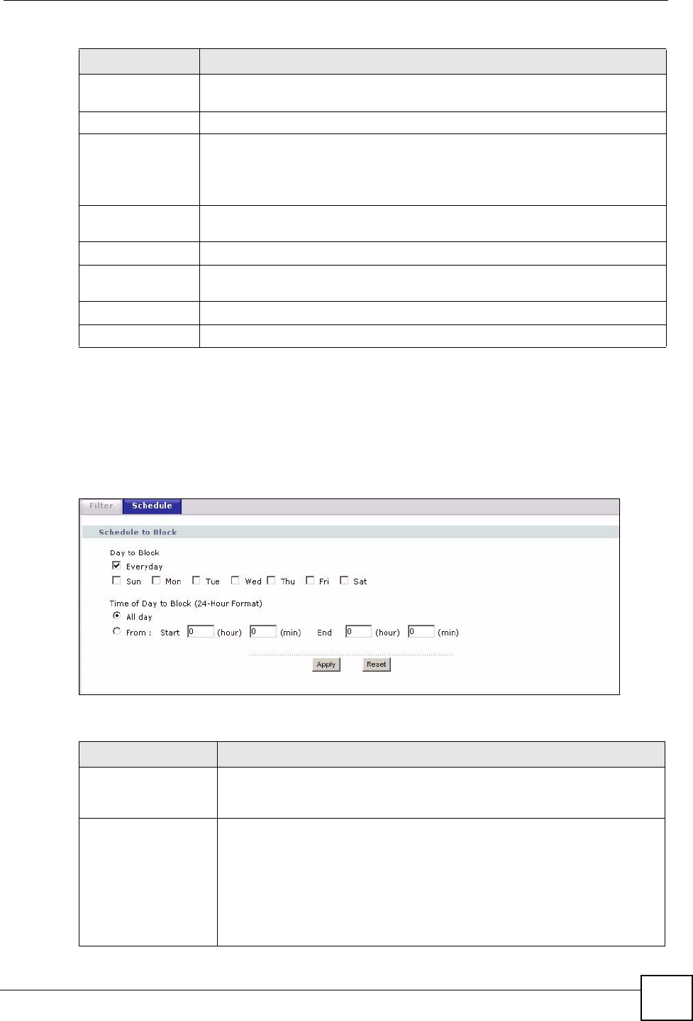
Figure 73 Security > Content Filter > Schedule
The following table describes the labels in this screen.
Keyword Type a keyword in this field. You may use any character (up to 64 characters).
Wildcards are not allowed. You can also enter a numerical IP address.
Keyword List This list displays the keywords already added.
Add Click Add after you have typed a keyword.
Repeat this procedure to add other keywords. Up to 64 keywords are allowed.
When you try to access a web page containing a keyword, you will get a
message telling you that the content filter is blocking this request.
Delete Highlight a keyword in the lower box and click Delete to remove it. The keyword
disappears from the text box after you click Apply.
Clear All Click this button to remove all of the listed keywords.
Denied Access
Message
Enter a message to be displayed when a user tries to access a restricted web
site. The default message is “Please contact your network administrator!!”
Apply Click Apply to save your changes.
Reset Click Reset to begin configuring this screen afresh
Table 52 Security > Content Filter > Filter
LABEL DESCRIPTION
Table 53 Security > Content Filter > Schedule
LABEL DESCRIPTION
Day to Block Select check boxes for the days that you want the NBG334W to perform
content filtering. Select the Everyday check box to have content filtering
turned on all days of the week.
Time of Day to Block
(24-Hour Format)
Time of Day to Block allows the administrator to define during which time
periods content filtering is enabled. Time of Day to Block restrictions only
apply to the keywords (see above). Restrict web server data, such as ActiveX,
Java, Cookies and Web Proxy are not affected.
Select All Day to have content filtering always active on the days selected in
Day to Block with time of day limitations not enforced.
Select From and enter the time period, in 24-hour format, during which
content filtering will be enforced.

Chapter 13 Content Filtering
NBG334W User’s Guide
136
13.6 Customizing Keyword Blocking URL Checking
You can use commands to set how much of a website’s URL the content filter is to check for
keyword blocking. See the appendices for information on how to access and use the command
interpreter.
13.6.1 Domain Name or IP Address URL Checking
By default, the NBG334W checks the URL’s domain name or IP address when performing
keyword blocking.
This means that the NBG334W checks the characters that come before the first slash in the
URL.
For example, with the URL www.zyxel.com.tw/news/pressroom.php, content filtering only
searches for keywords within www.zyxel.com.tw.
13.6.2 Full Path URL Checking
Full path URL checking has the NBG334W check the characters that come before the last
slash in the URL.
For example, with the URL www.zyxel.com.tw/news/pressroom.php, full path URL checking
searches for keywords within www.zyxel.com.tw/news/.
Use the ip urlfilter customize actionFlags 6 [disable | enable]
command to extend (or not extend) the keyword blocking search to include the URL's full
path.
13.6.3 File Name URL Checking
Filename URL checking has the NBG334W check all of the characters in the URL.
For example, filename URL checking searches for keywords within the URL
www.zyxel.com.tw/news/pressroom.php.
Use the ip urlfilter customize actionFlags 8 [disable | enable]
command to extend (or not extend) the keyword blocking search to include the URL's
complete filename.
Apply Click Apply to save your customized settings and exit this screen.
Reset Click Reset to begin configuring this screen afresh
Table 53 Security > Content Filter > Schedule
LABEL DESCRIPTION

137
PART IV
Management
Static Route Screens (139)
Bandwidth Management (143)
Remote Management (153)
Universal Plug-and-Play (UPnP) (159)

138
NBG334W User’s Guide 139
CHAPTER 14
Static Route Screens
This chapter shows you how to configure static routes for your NBG334W.
14.1 Static Route Overview
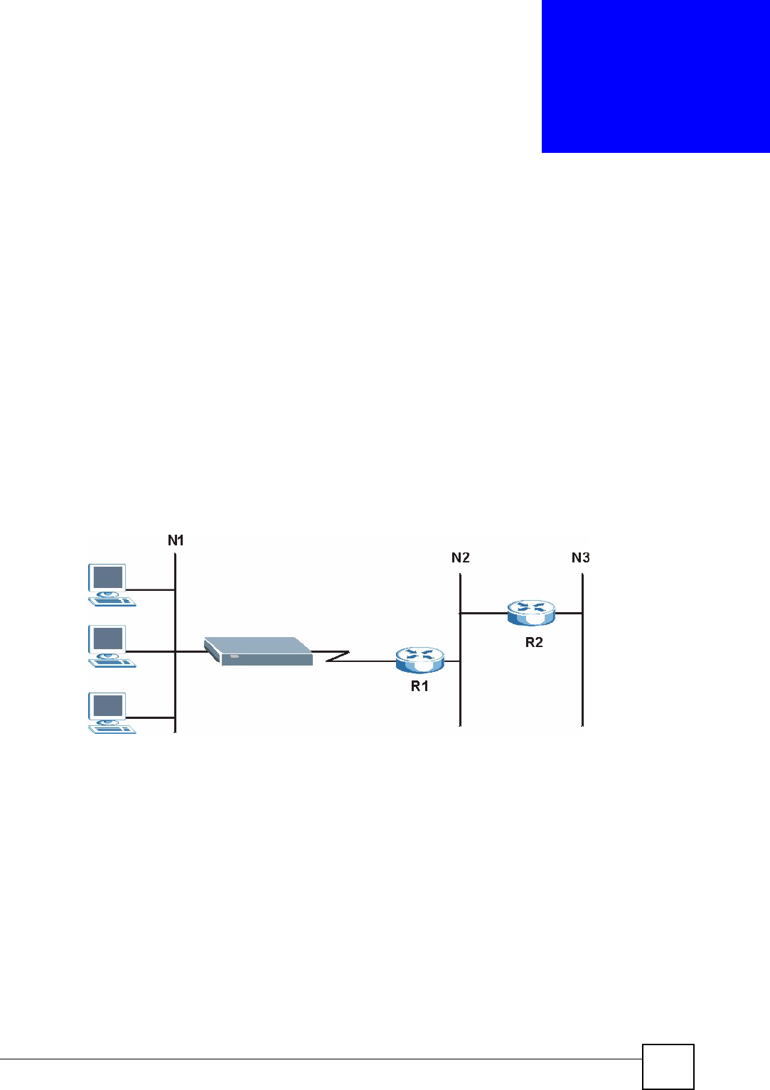
Each remote node specifies only the network to which the gateway is directly connected, and
the NBG334W has no knowledge of the networks beyond. For instance, the NBG334W knows
about network N2 in the following figure through remote node router R1. However, the
NBG334W is unable to route a packet to network N3 because it doesn't know that there is a
route through the same remote node router R1 (via gateway router R2). The static routes are
for you to tell the NBG334W about the networks beyond the remote nodes.
Figure 74 Example of Static Routing Topology
14.2 IP Static Route Screen
Click Management > Static Route to open the IP Static Route screen. The following screen
displays.
Chapter 14 Static Route Screens
NBG334W User’s Guide
140
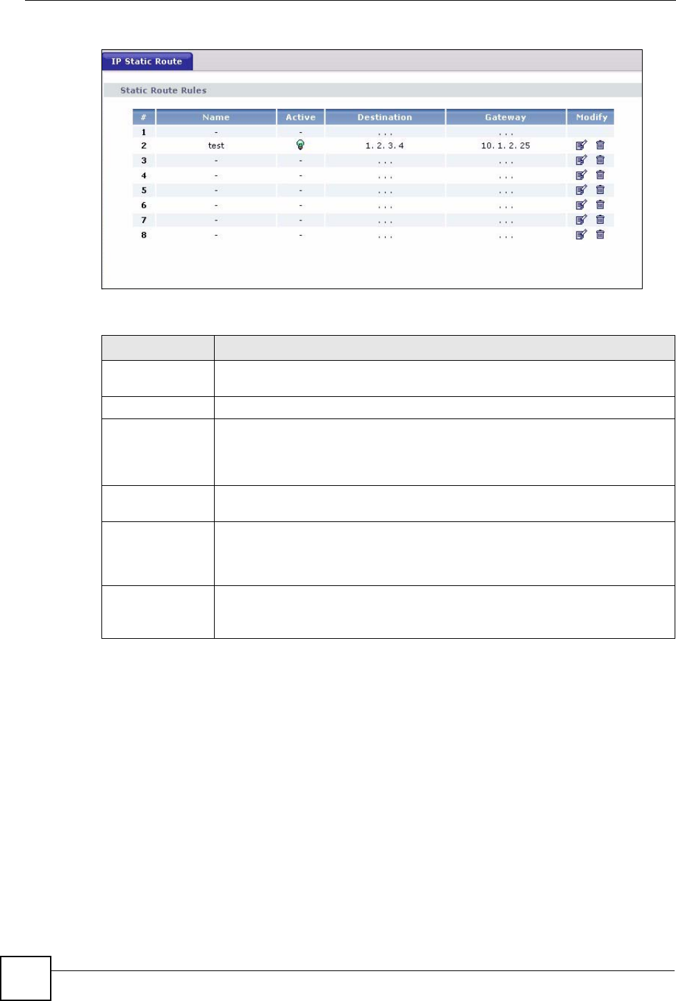
Figure 75 Management > Static Route > IP Static Route
The following table describes the labels in this screen.
14.2.1 Static Route Setup Screen
To edit a static route, click the edit icon under Modify. The following screen displays. Fill in
the required information for each static route.
Table 54 Management > Static Route > IP Static Route
LABEL DESCRIPTION
#This is the index number of an individual static route. The first entry is for the
default route and not editable.
Name This is the name that describes or identifies this route.
Active This icon is turned on when this static route is active.
Click the Edit icon under Modify and select the Active checkbox in the Static
Route Setup screen to enable the static route. Clear the checkbox to disable this
static route without having to delete the entry.
Destination This parameter specifies the IP network address of the final destination. Routing
is always based on network number.
Gateway This is the IP address of the gateway. The gateway is an immediate neighbor of
your NBG334W that will forward the packet to the destination. On the LAN, the
gateway must be a router on the same segment as your NBG334W; over the
WAN, the gateway must be the IP address of one of the remote nodes.
Modify Click the Edit icon to open the static route setup screen. Modify a static route or
create a new static route in the Static Route Setup screen.
Click the Remove icon to delete a static route.
Chapter 14 Static Route Screens
NBG334W User’s Guide 141
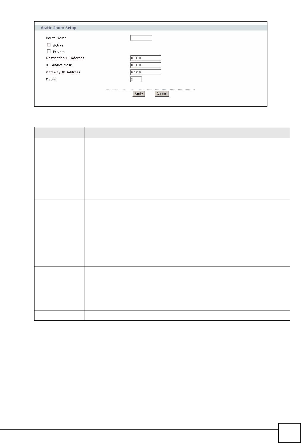
Figure 76 Management > Static Route > IP Static Route: Static Route Setup
The following table describes the labels in this screen.
Table 55 Management > Static Route > IP Static Route: Static Route Setup
LABEL DESCRIPTION
Route Name Enter the name of the IP static route. Leave this field blank to delete this static
route.
Active This field allows you to activate/deactivate this static route.
Private This parameter determines if the NBG334W will include this route to a remote
node in its RIP broadcasts.
Select this check box to keep this route private and not included in RIP
broadcasts. Clear this checkbox to propagate this route to other hosts through RIP
broadcasts.
Destination IP
Address
This parameter specifies the IP network address of the final destination. Routing is
always based on network number. If you need to specify a route to a single host,
use a subnet mask of 255.255.255.255 in the subnet mask field to force the
network number to be identical to the host ID.
IP Subnet Mask Enter the IP subnet mask here.
Gateway IP
Address
Enter the IP address of the gateway. The gateway is an immediate neighbor of
your NBG334W that will forward the packet to the destination. On the LAN, the
gateway must be a router on the same segment as your NBG334W; over the
WAN, the gateway must be the IP address of one of the Remote Nodes.
Metric Metric represents the “cost” of transmission for routing purposes. IP routing uses
hop count as the measurement of cost, with a minimum of 1 for directly connected
networks. Enter a number that approximates the cost for this link. The number
need not be precise, but it must be between 1 and 15. In practice, 2 or 3 is usually
a good number.
Apply Click Apply to save your changes back to the NBG334W.
Cancel Click Cancel to return to the previous screen and not save your changes.

Chapter 14 Static Route Screens
NBG334W User’s Guide
142

NBG334W User’s Guide 143
CHAPTER 15
Bandwidth Management
This chapter contains information about configuring bandwidth management, editing rules and
viewing the NBG334W’s bandwidth management logs.
15.1 Bandwidth Management Overview
ZyXEL’s Bandwidth Management allows you to specify bandwidth management rules based
on an application and/or subnet. You can allocate specific amounts of bandwidth capacity
(bandwidth budgets) to different bandwidth rules.
The NBG334W applies bandwidth management to traffic that it forwards out through an
interface. The NBG334W does not control the bandwidth of traffic that comes into an
interface.
Bandwidth management applies to all traffic flowing out of the router, regardless of the
traffic's source.
Traffic redirect or IP alias may cause LAN-to-LAN traffic to pass through the NBG334W and
be managed by bandwidth management.
• The sum of the bandwidth allotments that apply to the WAN interface (LAN to WAN,
WLAN to WAN, WAN to WAN / NBG334W) must be less than or equal to the
Upstream Bandwidth that you configure in the Bandwidth Management Advanced
screen.
• The sum of the bandwidth allotments that apply to the LAN port (WAN to LAN, WLAN
to LAN, LAN to LAN / NBG334W) must be less than or equal to 100,000 kbps (you
cannot configure the bandwidth budget for the LAN port).
• The sum of the bandwidth allotments that apply to the WLAN port (LAN to WLAN,
WAN to WLAN, WLAN to WLAN / NBG334W) must be less than or equal to 54,000
kbps (you cannot configure the bandwidth budget for the WLAN port).
15.2 Application-based Bandwidth Management
You can create bandwidth classes based on individual applications (like VoIP, Web, FTP, E-
mail and Video for example).
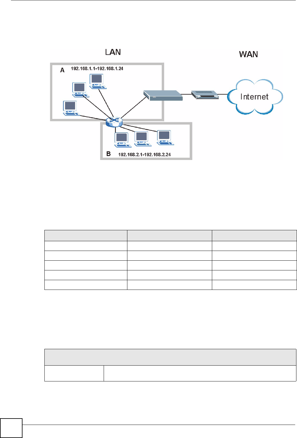
15.3 Subnet-based Bandwidth Management
You can create bandwidth classes based on subnets.
Chapter 15 Bandwidth Management
NBG334W User’s Guide
144
The following figure shows LAN subnets. You could configure one bandwidth class for
subnet A and another for subnet B.
Figure 77 Subnet-based Bandwidth Management Example
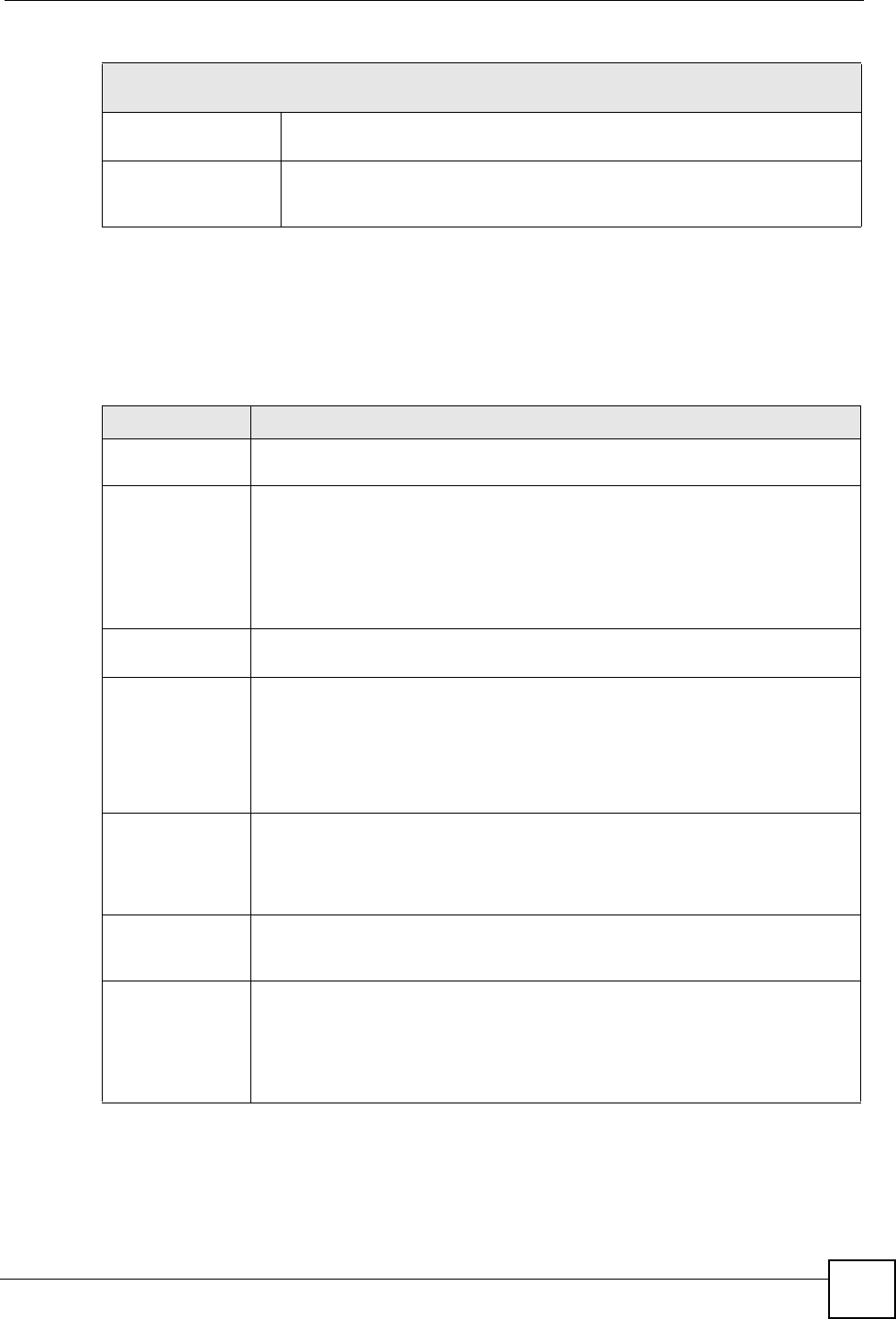
15.4 Application and Subnet-based Bandwidth Management
You could also create bandwidth classes based on a combination of a subnet and an
application. The following example table shows bandwidth allocations for application specific
traffic from separate LAN subnets.
15.5 Bandwidth Management Priorities
The following table describes the priorities that you can apply to traffic that the NBG334W
forwards out through an interface.
Table 56 Application and Subnet-based Bandwidth Management Example
TRAFFIC TYPE FROM SUBNET A FROM SUBNET B
VoIP 64 Kbps 64 Kbps
Web 64 Kbps 64 Kbps
FTP 64 Kbps 64 Kbps
E-mail 64 Kbps 64 Kbps
Video 64 Kbps 64 Kbps
Table 57 Bandwidth Management Priorities
PRIORITY LEVELS: TRAFFIC WITH A HIGHER PRIORITY GETS THROUGH FASTER WHILE
TRAFFIC WITH A LOWER PRIORITY IS DROPPED IF THE NETWORK IS CONGESTED.
High Typically used for voice traffic or video that is especially sensitive to jitter (jitter
is the variations in delay).
Chapter 15 Bandwidth Management
NBG334W User’s Guide 145
15.6 Predefined Bandwidth Management Services
The following is a description of the services that you can select and to which you can apply
media bandwidth management using the wizard screens.
Mid Typically used for “excellent effort” or better than best effort and would include
important business traffic that can tolerate some delay.
Low This is typically used for non-critical “background” traffic such as bulk
transfers that are allowed but that should not affect other applications and
users.
Table 57 Bandwidth Management Priorities
PRIORITY LEVELS: TRAFFIC WITH A HIGHER PRIORITY GETS THROUGH FASTER WHILE
TRAFFIC WITH A LOWER PRIORITY IS DROPPED IF THE NETWORK IS CONGESTED.
Table 58 Media Bandwidth Management Setup: Services
SERVICE DESCRIPTION
Xbox Live This is Microsoft’s online gaming service that lets you play multiplayer Xbox
games on the Internet via broadband technology. Xbox Live uses port 3074.
VoIP (SIP) Sending voice signals over the Internet is called Voice over IP or VoIP. Session
Initiated Protocol (SIP) is an internationally recognized standard for implementing
VoIP. SIP is an application-layer control (signaling) protocol that handles the
setting up, altering and tearing down of voice and multimedia sessions over the
Internet.
SIP is transported primarily over UDP but can also be transported over TCP,
using the default port number 5060.
FTP File Transfer Program enables fast transfer of files, including large files that may
not be possible by e-mail. FTP uses port number 21.
E-Mail Electronic mail consists of messages sent through a computer network to specific
groups or individuals. Here are some default ports for e-mail:
POP3 - port 110
IMAP - port 143
SMTP - port 25
HTTP - port 80
BitTorrent BitTorrent is a free P2P (peer-to-peer) sharing tool allowing you to distribute large
software and media files using ports 6881 to 6889. BitTorrent requires you to
search for a file with a searching engine yourself. It distributes files by corporation
and trading, that is, the client downloads the file in small pieces and share the
pieces with other peers to get other half of the file.
MSN Webcam MSN messenger allows you to chat online and send instant messages. If you use
MSN messenger and also have a webcam, you can send your image/photo in
real-time along with messages
WWW The World Wide Web (WWW) is an Internet system to distribute graphical, hyper-
linked information, based on Hyper Text Transfer Protocol (HTTP) - a client/server
protocol for the World Wide Web. The Web is not synonymous with the Internet;
rather, it is just one service on the Internet. Other services on the Internet include
Internet Relay Chat and Newsgroups. The Web is accessed through use of a
browser.

Chapter 15 Bandwidth Management
NBG334W User’s Guide
146
15.6.1 Services and Port Numbers
The commonly used services and port numbers are shown in the following table. Please refer
to RFC 1700 for further information about port numbers. Next to the name of the service, two
fields appear in brackets. The first field indicates the IP protocol type (TCP, UDP, or ICMP).
The second field indicates the IP port number that defines the service. (Note that there may be
more than one IP protocol type. For example, look at the DNS service. (UDP/TCP:53) means
UDP port 53 and TCP port 53.

Chapter 15 Bandwidth Management
NBG334W User’s Guide 147
Table 59 Commonly Used Services
SERVICE DESCRIPTION
AIM/New-ICQ(TCP:5190) AOL’s Internet Messenger service, used as a listening port by ICQ.
AUTH(TCP:113) Authentication protocol used by some servers.
BGP(TCP:179) Border Gateway Protocol.
BOOTP_CLIENT(UDP:68) DHCP Client.
BOOTP_SERVER(UDP:67) DHCP Server.
CU-SEEME(TCP/UDP:7648,
24032)
A popular videoconferencing solution from White Pines Software.
DNS(UDP/TCP:53) Domain Name Server, a service that matches web names (e.g.
www.zyxel.com) to IP numbers.
FINGER(TCP:79) Finger is a UNIX or Internet related command that can be used to
find out if a user is logged on.
FTP(TCP:20.21) File Transfer Program, a program to enable fast transfer of files,
including large files that may not be possible by e-mail.
H.323(TCP:1720) NetMeeting uses this protocol.
HTTP(TCP:80) Hyper Text Transfer Protocol - a client/server protocol for the world
wide web.
HTTPS(TCP:443) HTTPS is a secured http session often used in e-commerce.
ICQ(UDP:4000) This is a popular Internet chat program.
IKE(UDP:500) The Internet Key Exchange algorithm is used for key distribution and
management.
IPSEC_TUNNEL(AH:0) The IPSEC AH (Authentication Header) tunneling protocol uses this
service.
IPSEC_TUNNEL(ESP:0) The IPSEC ESP (Encapsulation Security Protocol) tunneling protocol
uses this service.
IRC(TCP/UDP:6667) This is another popular Internet chat program.
MSN Messenger(TCP:1863) Microsoft Networks’ messenger service uses this protocol.
MULTICAST(IGMP:0) Internet Group Multicast Protocol is used when sending packets to a
specific group of hosts.
NEW-ICQ(TCP:5190) An Internet chat program.
NEWS(TCP:144) A protocol for news groups.
NFS(UDP:2049) Network File System - NFS is a client/server distributed file service
that provides transparent file sharing for network environments.
NNTP(TCP:119) Network News Transport Protocol is the delivery mechanism for the
USENET newsgroup service.
PING(ICMP:0) Packet INternet Groper is a protocol that sends out ICMP echo
requests to test whether or not a remote host is reachable.
POP3(TCP:110) Post Office Protocol version 3 lets a client computer get e-mail from a
POP3 server through a temporary connection (TCP/IP or other).
PPTP(TCP:1723) Point-to-Point Tunneling Protocol enables secure transfer of data
over public networks. This is the control channel.
PPTP_TUNNEL(GRE:0) Point-to-Point Tunneling Protocol enables secure transfer of data
over public networks. This is the data channel.
RCMD(TCP:512) Remote Command Service.
REAL_AUDIO(TCP:7070) A streaming audio service that enables real time sound over the web.

Chapter 15 Bandwidth Management
NBG334W User’s Guide
148
15.7 Default Bandwidth Management Classes and Priorities
If you enable bandwidth management but do not configure a rule for critical traffic like VoIP,
the voice traffic may then get delayed due to insufficient bandwidth. With the automatic traffic
classifier feature activated, the NBG334W automatically assigns a default bandwidth
management class and priority to traffic that does not match any of the user-defined rules. The
traffic is classified based on the traffic type. Real-time traffic always gets higher priority over
other traffic.
The following table shows you the priorities between the three default classes (AutoClass_H,
AutoClass_M and Default Class) and user-defined rules. 6 is the highest priority.
REXEC(TCP:514) Remote Execution Daemon.
RLOGIN(TCP:513) Remote Login.
RTELNET(TCP:107) Remote Telnet.
RTSP(TCP/UDP:554) The Real Time Streaming (media control) Protocol (RTSP) is a
remote control for multimedia on the Internet.
SFTP(TCP:115) Simple File Transfer Protocol.
SMTP(TCP:25) Simple Mail Transfer Protocol is the message-exchange standard for
the Internet. SMTP enables you to move messages from one e-mail
server to another.
SNMP(TCP/UDP:161) Simple Network Management Program.
SNMP-TRAPS(TCP/UDP:162) Traps for use with the SNMP (RFC:1215).
SQL-NET(TCP:1521) Structured Query Language is an interface to access data on many
different types of database systems, including mainframes, midrange
systems, UNIX systems and network servers.
SSH(TCP/UDP:22) Secure Shell Remote Login Program.
STRM WORKS(UDP:1558) Stream Works Protocol.
SYSLOG(UDP:514) Syslog allows you to send system logs to a UNIX server.
TACACS(UDP:49) Login Host Protocol used for (Terminal Access Controller Access
Control System).
TELNET(TCP:23) Telnet is the login and terminal emulation protocol common on the
Internet and in UNIX environments. It operates over TCP/IP
networks. Its primary function is to allow users to log into remote host
systems.
TFTP(UDP:69) Trivial File Transfer Protocol is an Internet file transfer protocol
similar to FTP, but uses the UDP (User Datagram Protocol) rather
than TCP (Transmission Control Protocol).
VDOLIVE(TCP:7000) Another videoconferencing solution.
Table 59 Commonly Used Services
SERVICE DESCRIPTION
Table 60 Bandwidth Management Priority with Default Classes
CLASS TYPE PRIORITY
User-defined with high priority 6
AutoClass_H 5
User-defined with medium priority 4
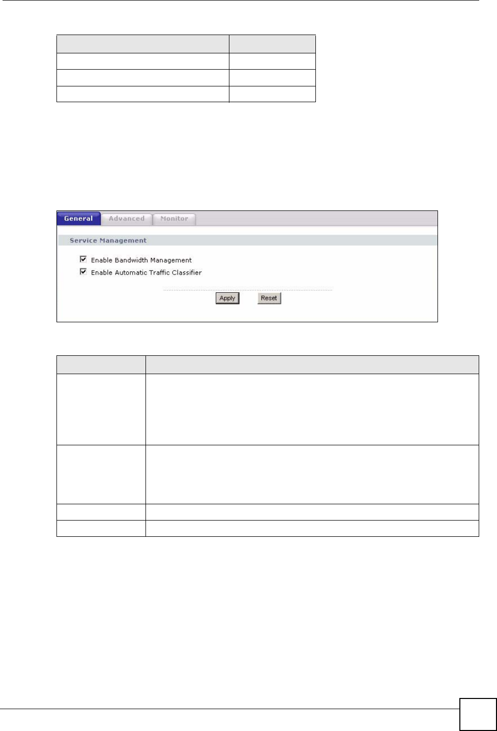
Chapter 15 Bandwidth Management
NBG334W User’s Guide 149
15.8 Bandwidth Management General Configuration
Click Management > Bandwidth MGMT to open the bandwidth management General
screen.
Figure 78 Management > Bandwidth MGMT > General
The following table describes the labels in this screen.
15.9 Bandwidth Management Advanced Configuration
Click Management > Bandwidth MGMT > Advanced to open the bandwidth management
Advanced screen.
AutoClass_M 3
User-defined with low priority 2
Default Class 1
Table 60 Bandwidth Management Priority with Default Classes
CLASS TYPE PRIORITY
Table 61 Management > Bandwidth MGMT > General
LABEL DESCRIPTION
Enable Bandwidth
Management
Select this check box to have the NBG334W apply bandwidth management.
Enable bandwidth management to give traffic that matches a bandwidth rule
priority over traffic that does not match a bandwidth rule.
Enabling bandwidth management also allows you to control the maximum or
minimum amounts of bandwidth that can be used by traffic that matches a
bandwidth rule.
Enable Automatic
Traffic Classifier
This field is only applicable when you select the Enable Bandwidth
Management check box.
Select this check box to have the NBG334W base on the default bandwidth
classes to apply bandwidth management. Real-time packets, such as VoIP
traffic always get higher priority.
Apply Click Apply to save your customized settings.
Reset Click Reset to begin configuring this screen afresh.
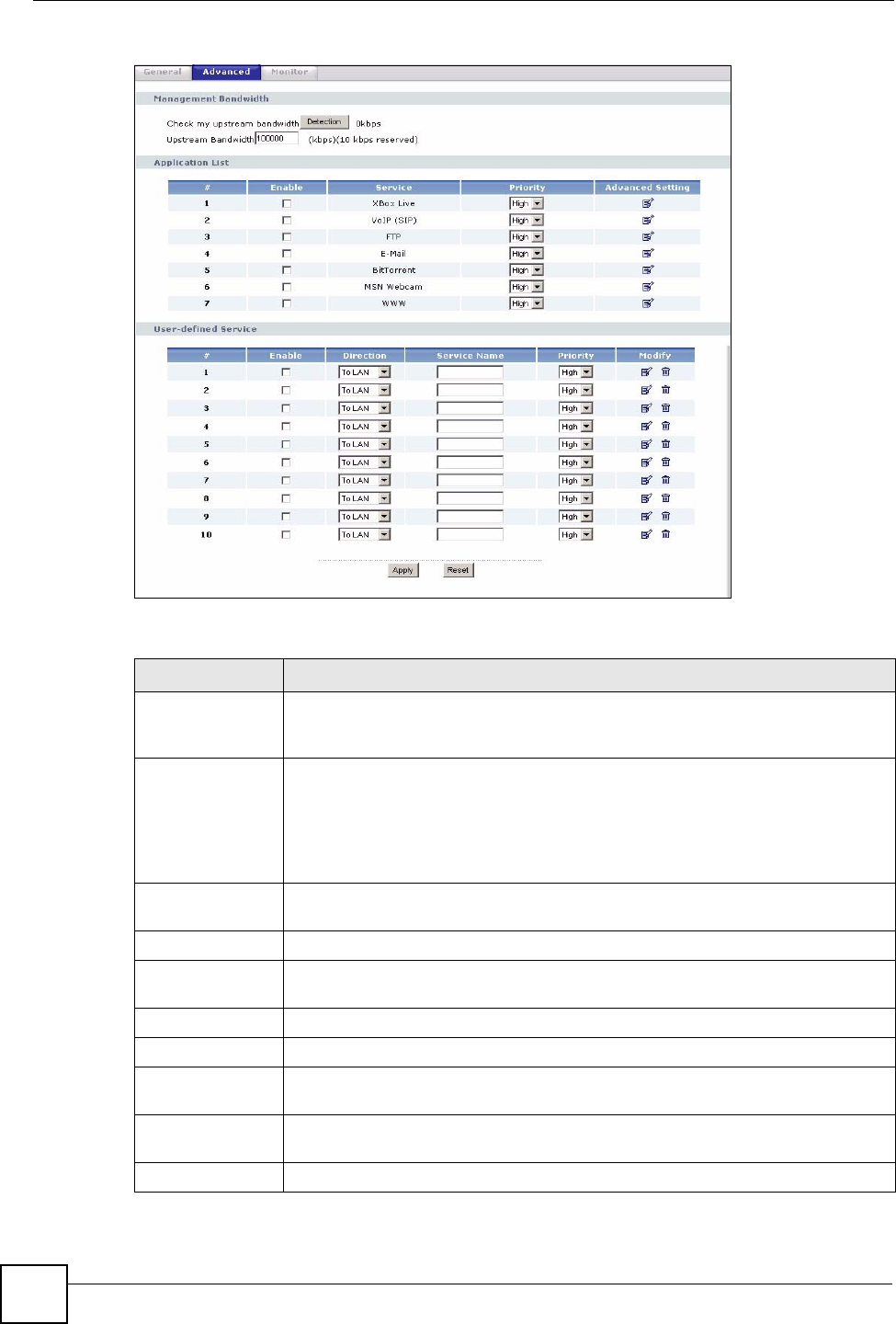
Chapter 15 Bandwidth Management
NBG334W User’s Guide
150
Figure 79 Management > Bandwidth MGMT > Advanced
The following table describes the labels in this screen.
Table 62 Management > Bandwidth MGMT > Advanced
LABEL DESCRIPTION
Check my
upstream
bandwidth
Click the Detection button to check the size of your upstream bandwidth.
Upstream
Bandwidth (kbps)
Enter the amount of bandwidth in kbps (2 to 100,000) that you want to allocate for
traffic. 20 kbps to 20,000 kbps is recommended.
The recommendation is to set this speed to be equal to or less than the speed of
the broadband device connected to the WAN port. For example, set the speed to
1000 Kbps (or less) if the broadband device connected to the WAN port has an
upstream speed of 1000 Kbps.
Application List Use this table to allocate specific amounts of bandwidth based on the pre-defined
service.
#This is the number of an individual bandwidth management rule.
Enable Select this check box to have the NBG334W apply this bandwidth management
rule.
Service This is the name of the service.
Priority Select a priority from the drop down list box. Choose High, Mid or Low.
Advanced Setting Click the Edit icon to open the Rule Configuration screen where you can modify
the rule.
User-defined
Service
Use this table to allocate specific amounts of bandwidth to specific applications
and/or subnets.
#This is the number of an individual bandwidth management rule.
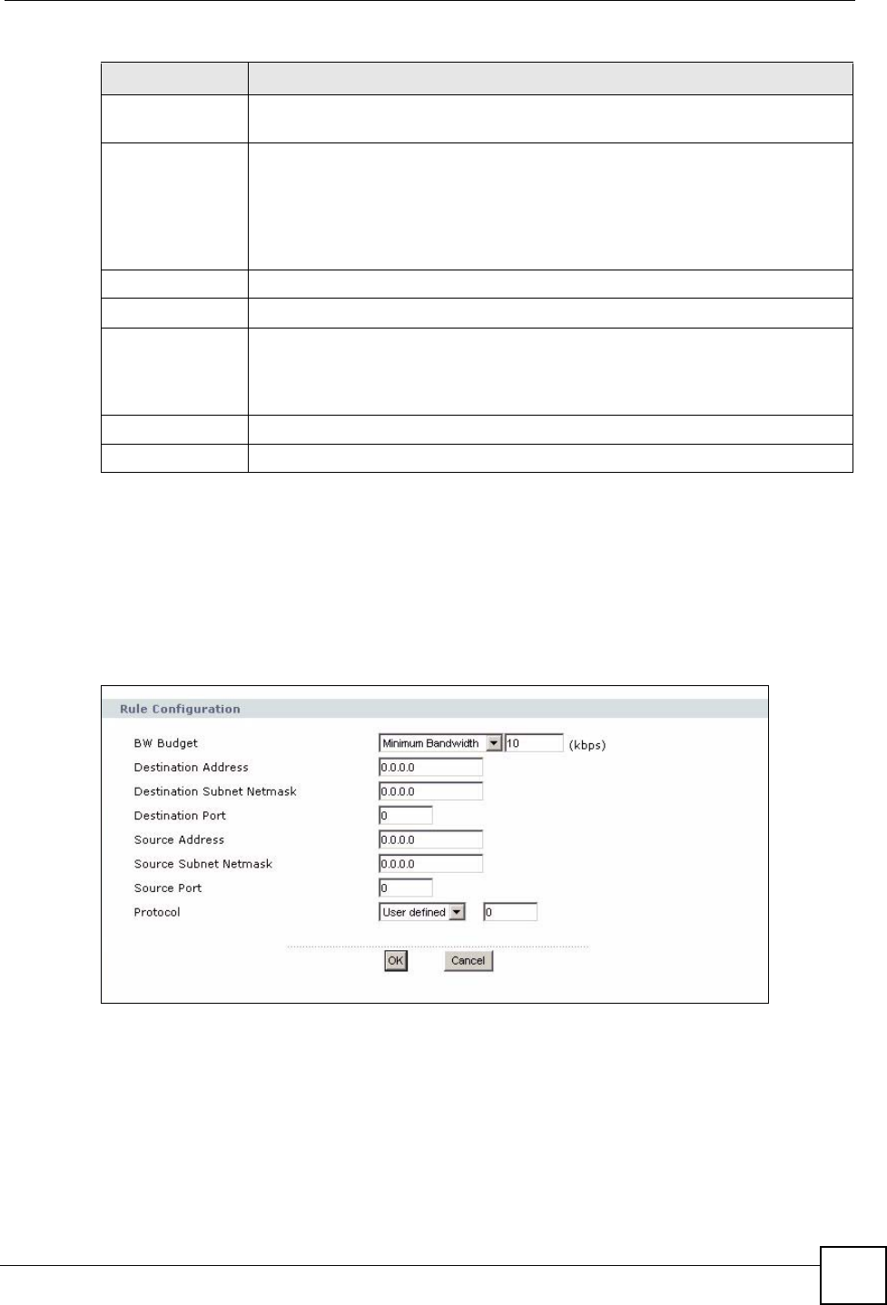
Chapter 15 Bandwidth Management
NBG334W User’s Guide 151
15.9.1 Rule Configuration
If you want to edit a bandwidth management rule for other applications and/or subnets, click
the Edit icon in the Application List or User-defined Service table of the Advanced screen.
The following screen displays.
Figure 80 Management > Bandwidth MGMT > Advanced: User-defined Service Rule
Configuration
The following table describes the labels in this screen
Table 63 Management > Bandwidth MGMT > Advanced: User-defined Service Rule
Enable Select this check box to have the NBG334W apply this bandwidth management
rule.
Direction Select To LAN to apply bandwidth management to traffic that the NBG334W
forwards to the LAN.
Select To WAN to apply bandwidth management to traffic that the NBG334W
forwards to the WAN.
Select To WLAN to apply bandwidth management to traffic that the NBG334W
forwards to the WLAN.
Service Name Enter a descriptive name of up to 19 alphanumeric characters, including spaces.
Priority Select a priority from the drop down list box. Choose High, Mid or Low.
Modify Click the Edit icon to open the Rule Configuration screen. Modify an existing rule
or create a new rule in the Rule Configuration screen. See Section 15.9.1 on
page 151 for more information.
Click the Remove icon to delete a rule.
Apply Click Apply to save your customized settings.
Reset Click Reset to begin configuring this screen afresh.
Table 62 Management > Bandwidth MGMT > Advanced (continued)
LABEL DESCRIPTION
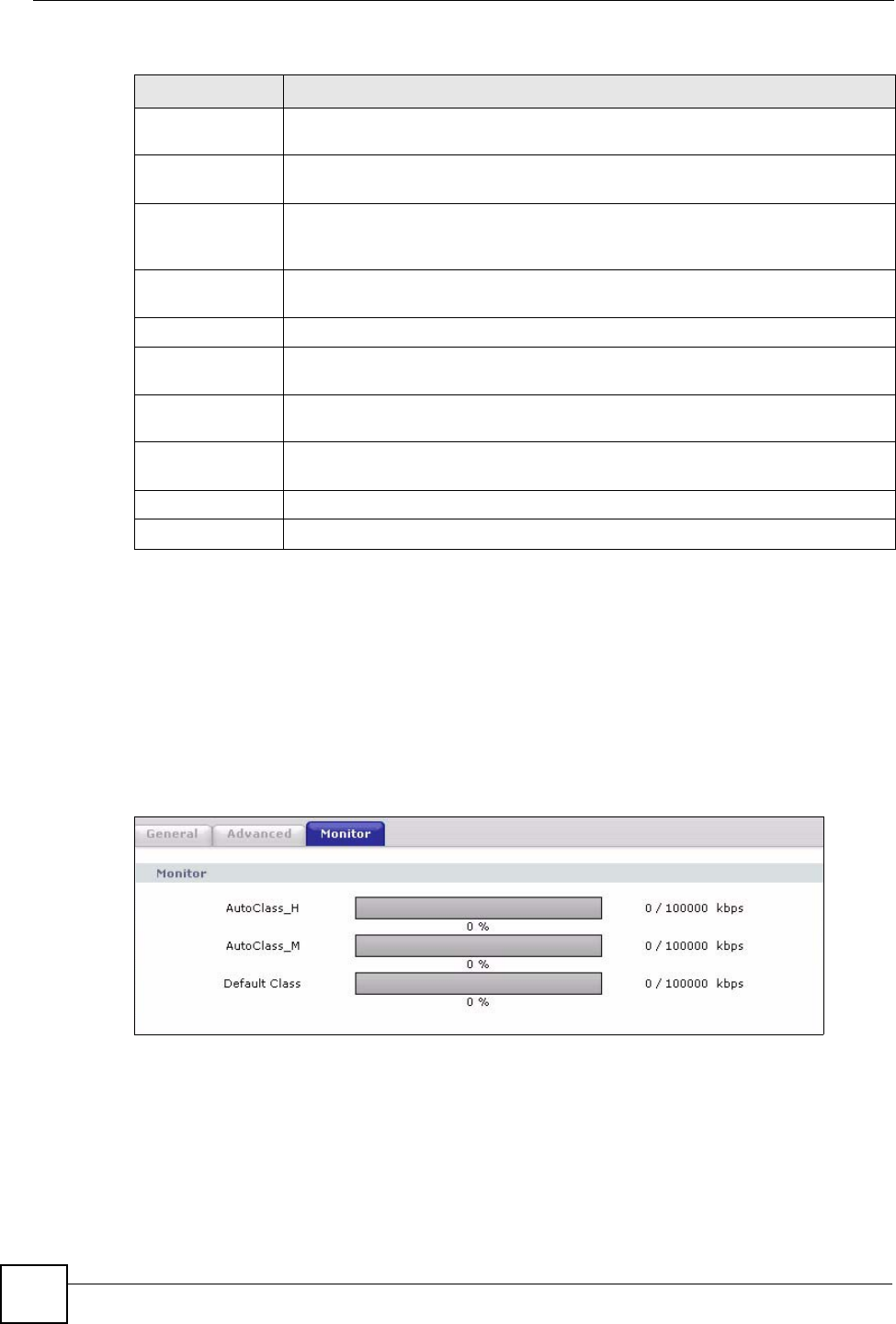
Chapter 15 Bandwidth Management
NBG334W User’s Guide
152
Configuration
15.10 Bandwidth Management Monitor
Click Management > Bandwidth MGMT > Monitor to open the bandwidth management
Monitor screen. View the bandwidth usage of the WAN configured bandwidth rules. This is
also shown as bandwidth usage over the bandwidth budget for each rule. The gray section of
the bar represents the percentage of unused bandwidth and the blue color represents the
percentage of bandwidth in use.
Figure 81 Management > Bandwidth MGMT > Monitor
LABEL DESCRIPTION
BW Budget Select Maximum Bandwidth or Minimum Bandwidth and specify the maximum
or minimum bandwidth allowed for the rule in kilobits per second.
Destination
Address
Enter the destination IP address in dotted decimal notation.
Destination
Subnet Netmask
Enter the destination subnet mask. This field is N/A if you do not specify a
Destination Address. Refer to the appendices for more information on IP
subnetting.
Destination Port Enter the port number of the destination. See Table 59 on page 147 for some
common services and port numbers.
Source Address Enter the source IP address in dotted decimal notation.
Source Subnet
Netmask
Enter the destination subnet mask. This field is N/A if you do not specify a Source
Address. Refer to the appendices for more information on IP subnetting.
Source Port Enter the port number of the source. See Table 59 on page 147 for some common
services and port numbers.
Protocol Select the protocol (TCP or UDP) or select User defined and enter the protocol
(service type) number.
OK Click OK to save your customized settings.
Cancel Click Cancel to exit this screen without saving.

NBG334W User’s Guide 153
CHAPTER 16
Remote Management
This chapter provides information on the Remote Management screens.
16.1 Remote Management Overview
Remote management allows you to determine which services/protocols can access which
NBG334W interface (if any) from which computers.
"When you configure remote management to allow management from the
WAN, you still need to configure a firewall rule to allow access. See the firewall
chapters for details on configuring firewall rules.
You may manage your NBG334W from a remote location via:
"When you choose WAN or LAN & WAN, you still need to configure a firewall
rule to allow access.
To disable remote management of a service, select Disable in the corresponding Server
Access field.
You may only have one remote management session running at a time. The NBG334W
automatically disconnects a remote management session of lower priority when another
remote management session of higher priority starts. The priorities for the different types of
remote management sessions are as follows.
1Telnet
2HTTP
16.1.1 Remote Management Limitations
Remote management over LAN or WAN will not work when:
• Internet (WAN only) • ALL (LAN and WAN)
• LAN only • Neither (Disable).
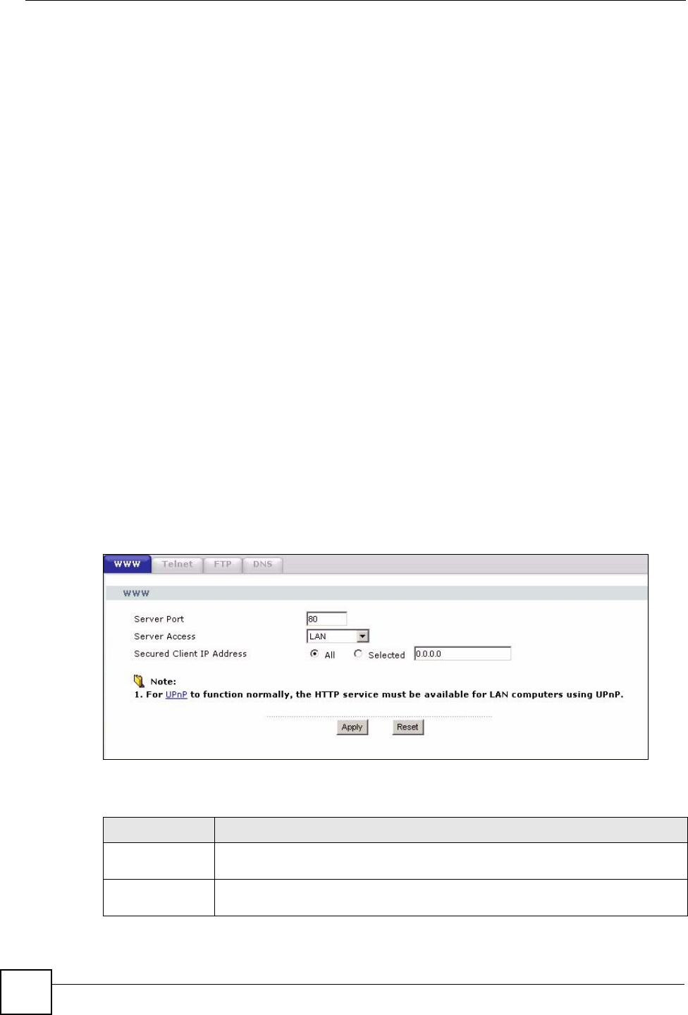
Chapter 16 Remote Management
NBG334W User’s Guide
154
1You have disabled that service in one of the remote management screens.
2The IP address in the Secured Client IP Address field does not match the client IP
address. If it does not match, the NBG334W will disconnect the session immediately.
3There is already another remote management session with an equal or higher priority
running. You may only have one remote management session running at one time.
4There is a firewall rule that blocks it.
16.1.2 Remote Management and NAT
When NAT is enabled:
• Use the NBG334W’s WAN IP address when configuring from the WAN.
• Use the NBG334W’s LAN IP address when configuring from the LAN.
16.1.3 System Timeout
There is a default system management idle timeout of five minutes (three hundred seconds).
The NBG334W automatically logs you out if the management session remains idle for longer
than this timeout period. The management session does not time out when a statistics screen is
polling. You can change the timeout period in the System screen
16.2 WWW Screen
To change your NBG334W’s World Wide Web settings, click Management > Remote
MGMT to display the WWW screen.
Figure 82 Management > Remote MGMT > WWW
The following table describes the labels in this screen
Table 64 Management > Remote MGMT > WWW
LABEL DESCRIPTION
Server Port You may change the server port number for a service if needed, however you must
use the same port number in order to use that service for remote management.
Server Access Select the interface(s) through which a computer may access the NBG334W using
this service.
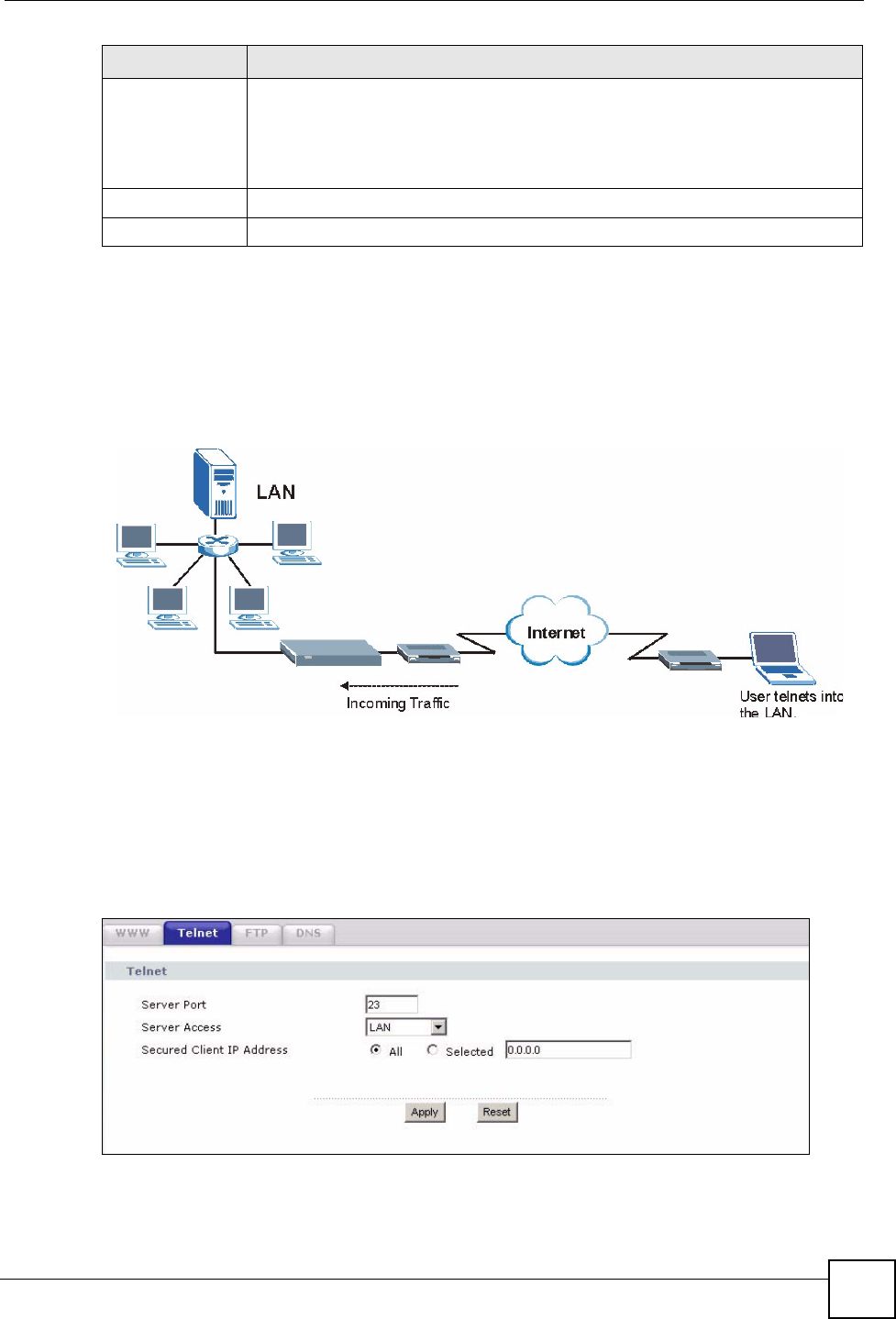
Chapter 16 Remote Management
NBG334W User’s Guide 155
16.3 Telnet
You can configure your NBG334W for remote Telnet access as shown next. The administrator
uses Telnet from a computer on a remote network to access the NBG334W.
Figure 83 Telnet Configuration on a TCP/IP Network
16.4 Telnet Screen
To change your NBG334W’s Telnet settings, click Management > Remote MGMT >
Telne t. The following screen displays.
Figure 84 Management > Remote MGMT > Telnet
Secured Client IP
Address
A secured client is a “trusted” computer that is allowed to communicate with the
NBG334W using this service.
Select All to allow any computer to access the NBG334W using this service.
Choose Selected to just allow the computer with the IP address that you specify to
access the NBG334W using this service.
Apply Click Apply to save your customized settings and exit this screen.
Reset Click Reset to begin configuring this screen afresh.
LABEL DESCRIPTION
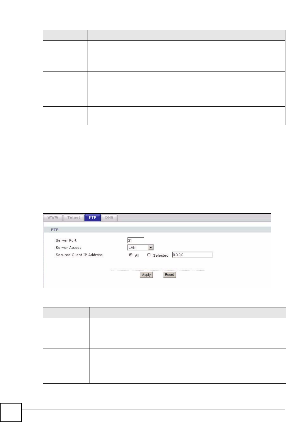
Chapter 16 Remote Management
NBG334W User’s Guide
156
The following table describes the labels in this screen.
16.5 FTP Screen
You can upload and download the NBG334W’s firmware and configuration files using FTP,
please see the chapter on firmware and configuration file maintenance for details. To use this
feature, your computer must have an FTP client.
To change your NBG334W’s FTP settings, click Management > Remote MGMT > FTP.
The screen appears as shown.
Figure 85 Management > Remote MGMT > FTP
The following table describes the labels in this screen.
Table 65 Management > Remote MGMT > Telnet
LABEL DESCRIPTION
Server Port You may change the server port number for a service if needed, however you must
use the same port number in order to use that service for remote management.
Server Access Select the interface(s) through which a computer may access the NBG334W using
this service.
Secured Client
IP Address
A secured client is a “trusted” computer that is allowed to communicate with the
NBG334W using this service.
Select All to allow any computer to access the NBG334W using this service.
Choose Selected to just allow the computer with the IP address that you specify to
access the NBG334W using this service.
Apply Click Apply to save your customized settings and exit this screen.
Reset Click Reset to begin configuring this screen afresh.
Table 66 Management > Remote MGMT > FTP
LABEL DESCRIPTION
Server Port You may change the server port number for a service if needed, however you must
use the same port number in order to use that service for remote management.
Server Access Select the interface(s) through which a computer may access the NBG334W using
this service.
Secured Client IP
Address
A secured client is a “trusted” computer that is allowed to communicate with the
NBG334W using this service.
Select All to allow any computer to access the NBG334W using this service.
Choose Selected to just allow the computer with the IP address that you specify to
access the NBG334W using this service.
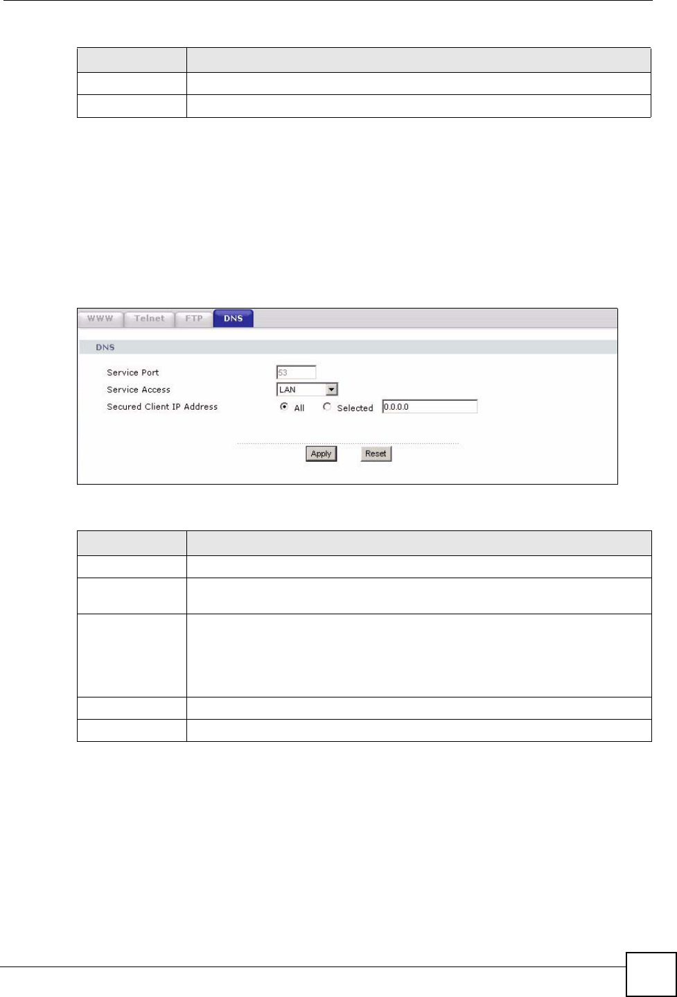
Chapter 16 Remote Management
NBG334W User’s Guide 157
16.6 DNS Screen
Use DNS (Domain Name System) to map a domain name to its corresponding IP address and
vice versa. Refer to the chapter on Wizard Setup for background information.
To change your NBG334W’s DNS settings, click Management > Remote MGMT > DNS.
The screen appears as shown.
Figure 86 Management > Remote MGMT > DNS
The following table describes the labels in this screen.
Apply Click Apply to save your customized settings and exit this screen.
Reset Click Reset to begin configuring this screen afresh.
Table 66 Management > Remote MGMT > FTP
LABEL DESCRIPTION
Table 67 Management > Remote MGMT > DNS
LABEL DESCRIPTION
Server Port The DNS service port number is 53 and cannot be changed here.
Server Access Select the interface(s) through which a computer may send DNS queries to the
NBG334W.
Secured Client IP
Address
A secured client is a “trusted” computer that is allowed to send DNS queries to the
NBG334W.
Select All to allow any computer to send DNS queries to the NBG334W.
Choose Selected to just allow the computer with the IP address that you specify to
send DNS queries to the NBG334W.
Apply Click Apply to save your customized settings and exit this screen.
Reset Click Reset to begin configuring this screen afresh.

Chapter 16 Remote Management
NBG334W User’s Guide
158

NBG334W User’s Guide 159
CHAPTER 17
Universal Plug-and-Play (UPnP)
This chapter introduces the UPnP feature in the web configurator.
17.1 Introducing Universal Plug and Play
Universal Plug and Play (UPnP) is a distributed, open networking standard that uses TCP/IP
for simple peer-to-peer network connectivity between devices. A UPnP device can
dynamically join a network, obtain an IP address, convey its capabilities and learn about other
devices on the network. In turn, a device can leave a network smoothly and automatically
when it is no longer in use.
See Section 17.3 on page 160 for configuration instructions.
17.1.1 How do I know if I'm using UPnP?
UPnP hardware is identified as an icon in the Network Connections folder (Windows XP).
Each UPnP compatible device installed on your network will appear as a separate icon.
Selecting the icon of a UPnP device will allow you to access the information and properties of
that device.
17.1.2 NAT Traversal
UPnP NAT traversal automates the process of allowing an application to operate through
NAT. UPnP network devices can automatically configure network addressing, announce their
presence in the network to other UPnP devices and enable exchange of simple product and
service descriptions. NAT traversal allows the following:
• Dynamic port mapping
• Learning public IP addresses
• Assigning lease times to mappings
Windows Messenger is an example of an application that supports NAT traversal and UPnP.
See the NAT chapter for more information on NAT.
17.1.3 Cautions with UPnP
The automated nature of NAT traversal applications in establishing their own services and
opening firewall ports may present network security issues. Network information and
configuration may also be obtained and modified by users in some network environments.
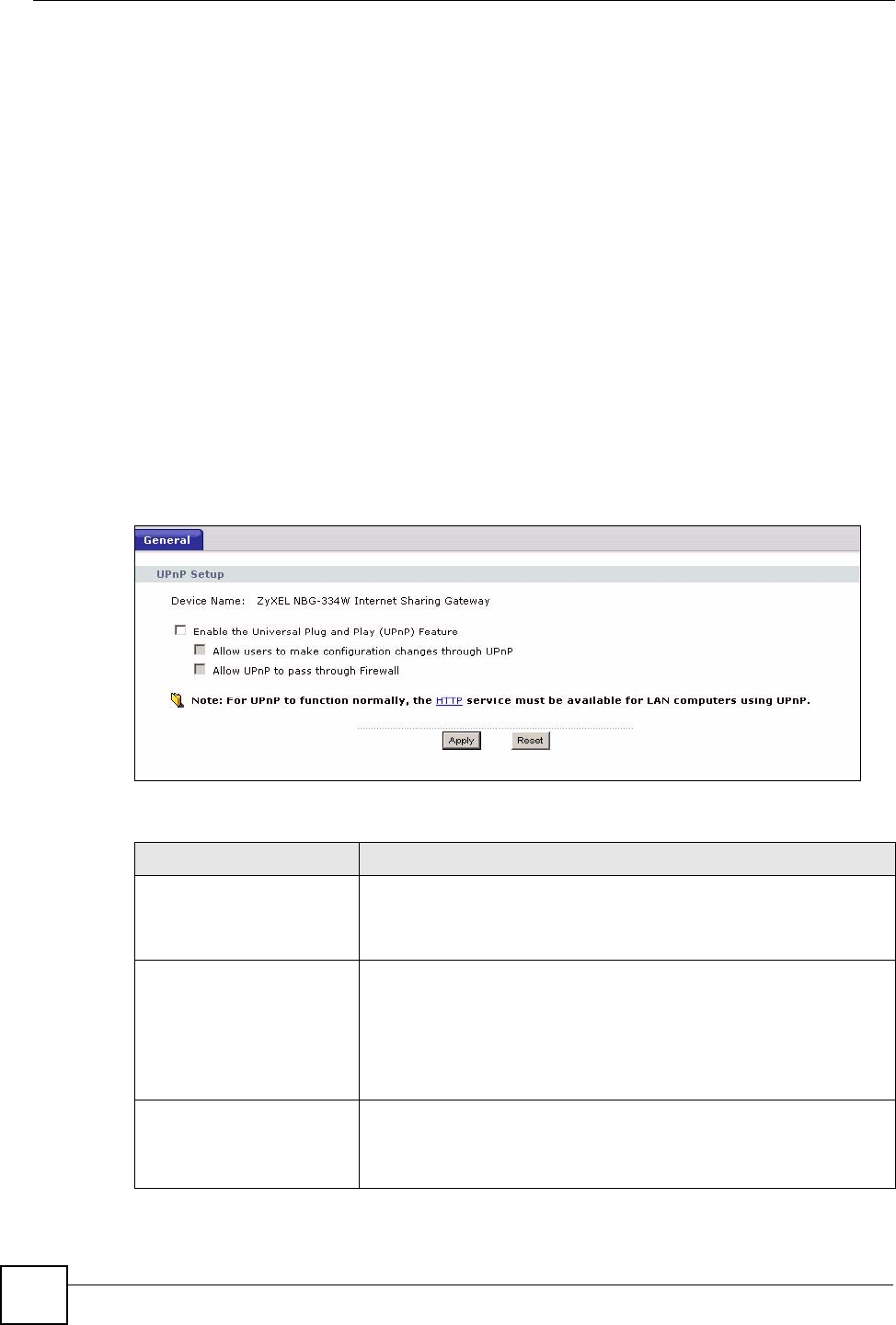
Chapter 17 Universal Plug-and-Play (UPnP)
NBG334W User’s Guide
160
When a UPnP device joins a network, it announces its presence with a multicast message. For
security reasons, the NBG334W allows multicast messages on the LAN only.
All UPnP-enabled devices may communicate freely with each other without additional
configuration. Disable UPnP if this is not your intention.
17.2 UPnP and ZyXEL
ZyXEL has achieved UPnP certification from the Universal Plug and Play Forum UPnP™
Implementers Corp. (UIC). ZyXEL's UPnP implementation supports Internet Gateway Device
(IGD) 1.0.
See the following sections for examples of installing and using UPnP.
17.3 UPnP Screen
Click the Management > UPnP to display the UPnP screen.
Figure 87 Management > UPnP > General
The following table describes the labels in this screen.
Table 68 Management > UPnP > General
LABEL DESCRIPTION
Enable the Universal Plug
and Play (UPnP) Feature
Select this check box to activate UPnP. Be aware that anyone could
use a UPnP application to open the web configurator's login screen
without entering the NBG334W's IP address (although you must still
enter the password to access the web configurator).
Allow users to make
configuration changes
through UPnP
Select this check box to allow UPnP-enabled applications to
automatically configure the NBG334W so that they can communicate
through the NBG334W, for example by using NAT traversal, UPnP
applications automatically reserve a NAT forwarding port in order to
communicate with another UPnP enabled device; this eliminates the
need to manually configure port forwarding for the UPnP enabled
application.
Allow UPnP to pass through
Firewall
Select this check box to allow traffic from UPnP-enabled applications to
bypass the firewall.
Clear this check box to have the firewall block all UPnP application
packets (for example, MSN packets).
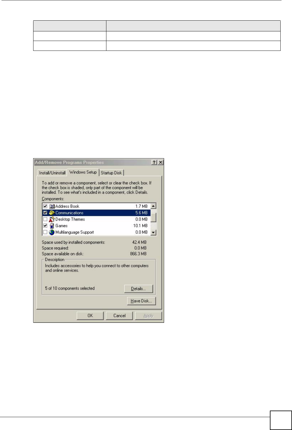
Chapter 17 Universal Plug-and-Play (UPnP)
NBG334W User’s Guide 161
17.4 Installing UPnP in Windows Example
This section shows how to install UPnP in Windows Me and Windows XP.
17.4.0.1 Installing UPnP in Windows Me
Follow the steps below to install the UPnP in Windows Me.
1Click Start and Control Panel. Double-click Add/Remove Programs.
2Click on the Windows Setup tab and select Communication in the Components
selection box. Click Details.
Figure 88 Add/Remove Programs: Windows Setup: Communication
3In the Communications window, select the Universal Plug and Play check box in the
Components selection box.
Apply Click Apply to save the setting to the NBG334W.
Cancel Click Cancel to return to the previously saved settings.
Table 68 Management > UPnP > General
LABEL DESCRIPTION
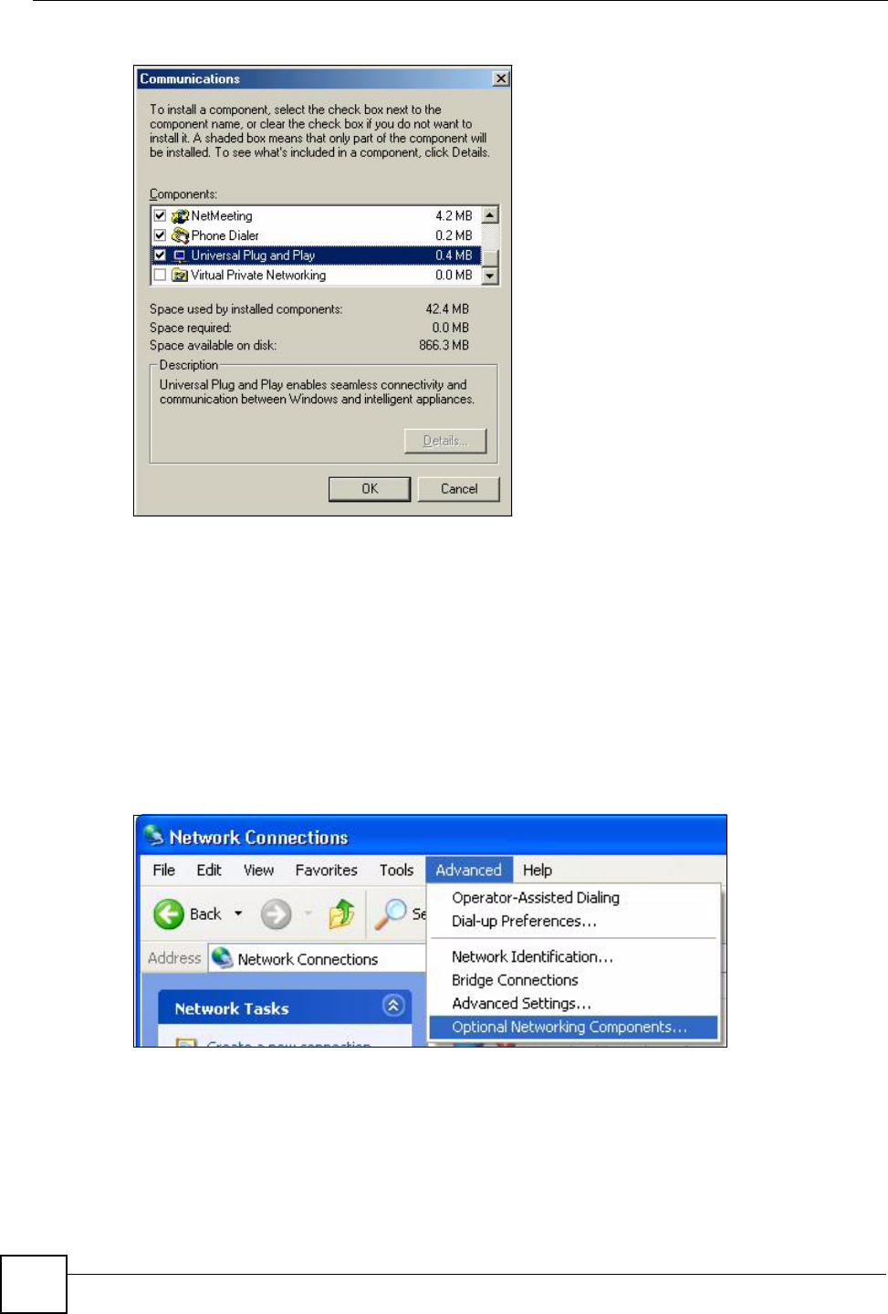
Chapter 17 Universal Plug-and-Play (UPnP)
NBG334W User’s Guide
162
Figure 89 Add/Remove Programs: Windows Setup: Communication: Components
4Click OK to go back to the Add/Remove Programs Properties window and click
Next.
5Restart the computer when prompted.
Installing UPnP in Windows XP
Follow the steps below to install the UPnP in Windows XP.
1Click Start and Control Panel.
2Double-click Network Connections.
3In the Network Connections window, click Advanced in the main menu and select
Optional Networking Components ….
Figure 90 Network Connections
4The Windows Optional Networking Components Wizard window displays. Select
Networking Service in the Components selection box and click Details.
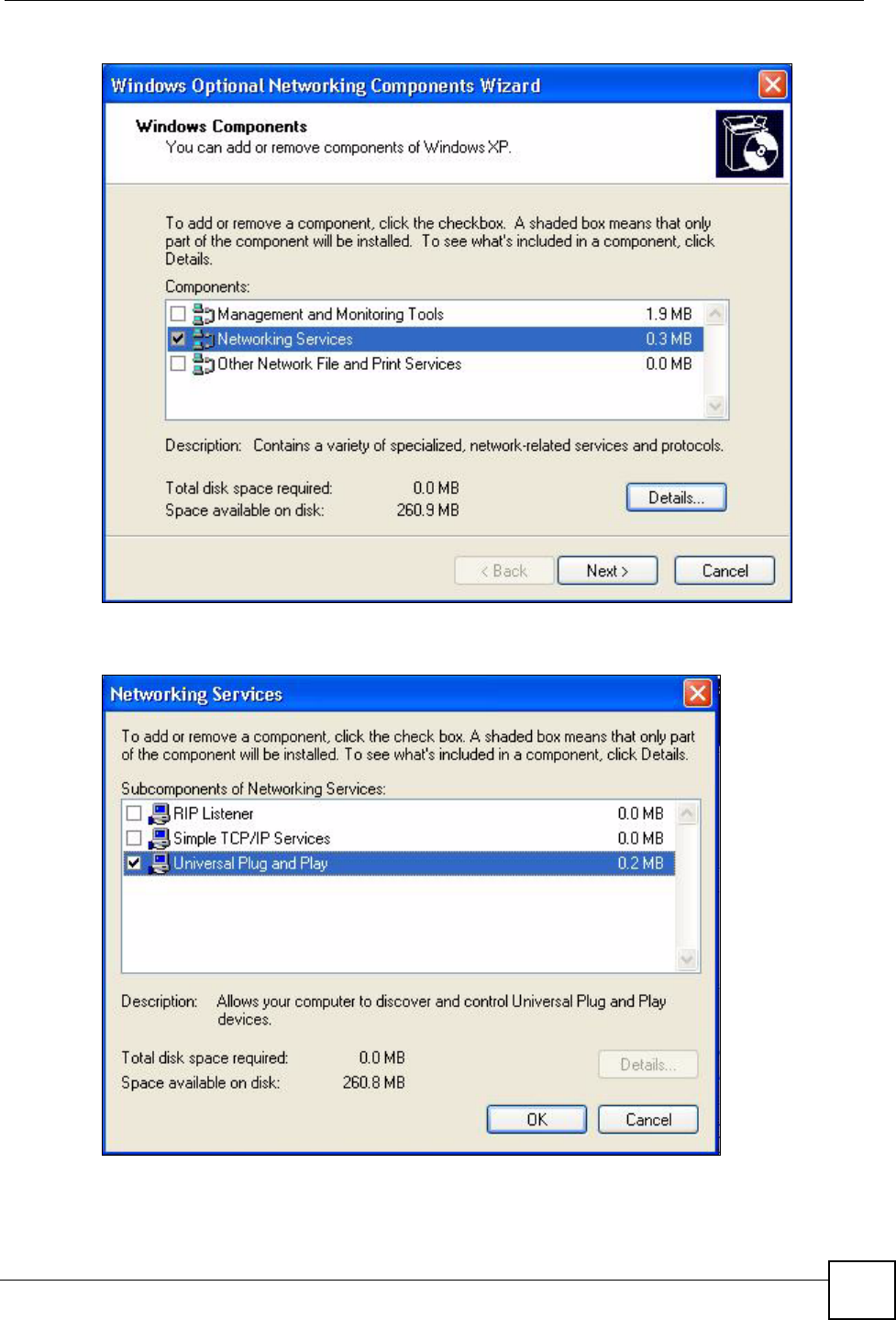
Chapter 17 Universal Plug-and-Play (UPnP)
NBG334W User’s Guide 163
Figure 91 Windows Optional Networking Components Wizard
5In the Networking Services window, select the Universal Plug and Play check box.
Figure 92 Networking Services
6Click OK to go back to the Windows Optional Networking Component Wizard
window and click Next.
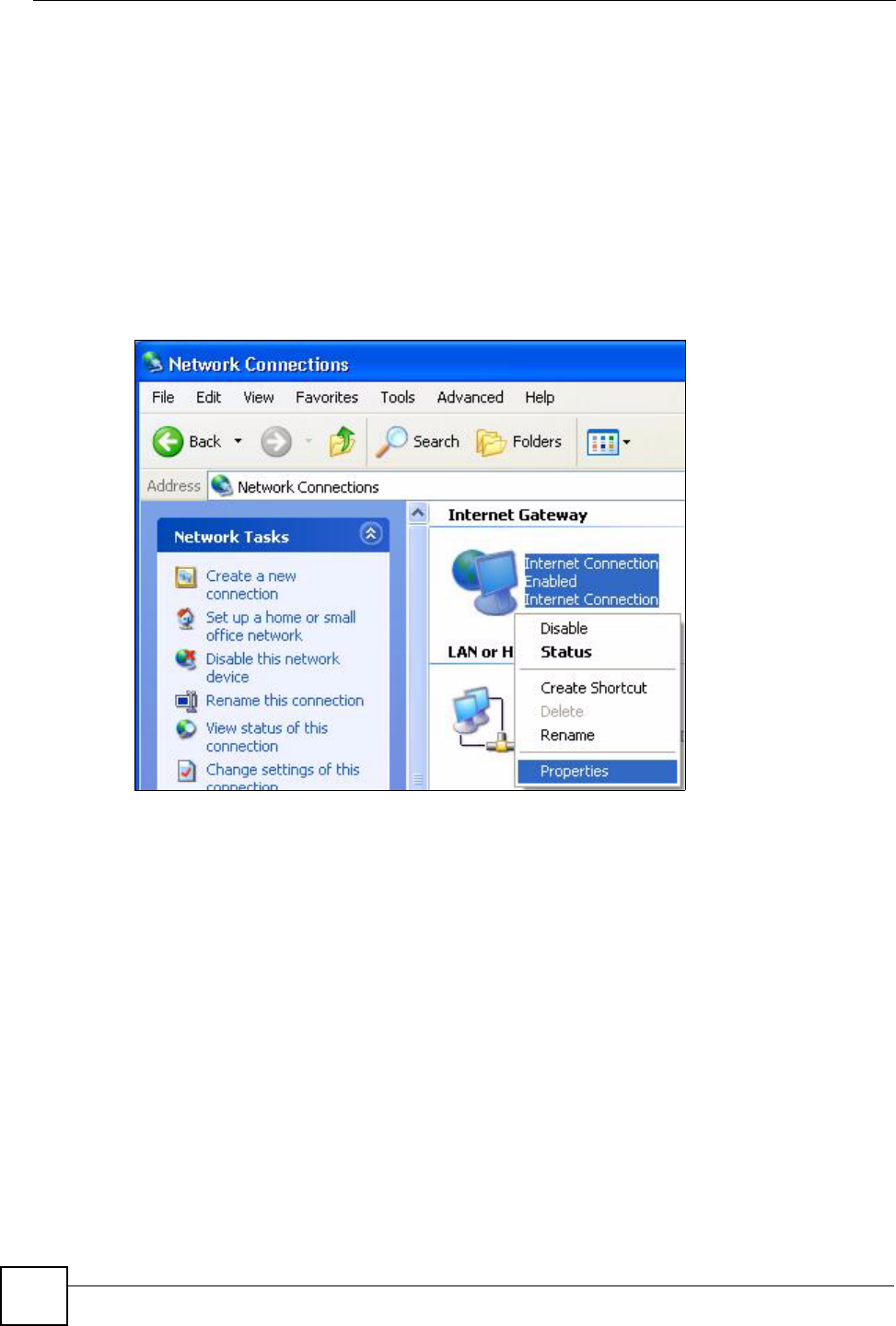
Chapter 17 Universal Plug-and-Play (UPnP)
NBG334W User’s Guide
164
17.4.0.2 Using UPnP in Windows XP Example
This section shows you how to use the UPnP feature in Windows XP. You must already have
UPnP installed in Windows XP and UPnP activated on the NBG334W.
Make sure the computer is connected to a LAN port of the NBG334W. Turn on your computer
and the NBG334W.
Auto-discover Your UPnP-enabled Network Device
1Click Start and Control Panel. Double-click Network Connections. An icon displays
under Internet Gateway.
2Right-click the icon and select Properties.
Figure 93 Network Connections
3In the Internet Connection Properties window, click Settings to see the port mappings
there were automatically created.
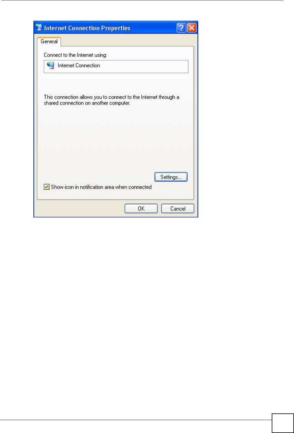
Chapter 17 Universal Plug-and-Play (UPnP)
NBG334W User’s Guide 165
Figure 94 Internet Connection Properties
4You may edit or delete the port mappings or click Add to manually add port mappings.
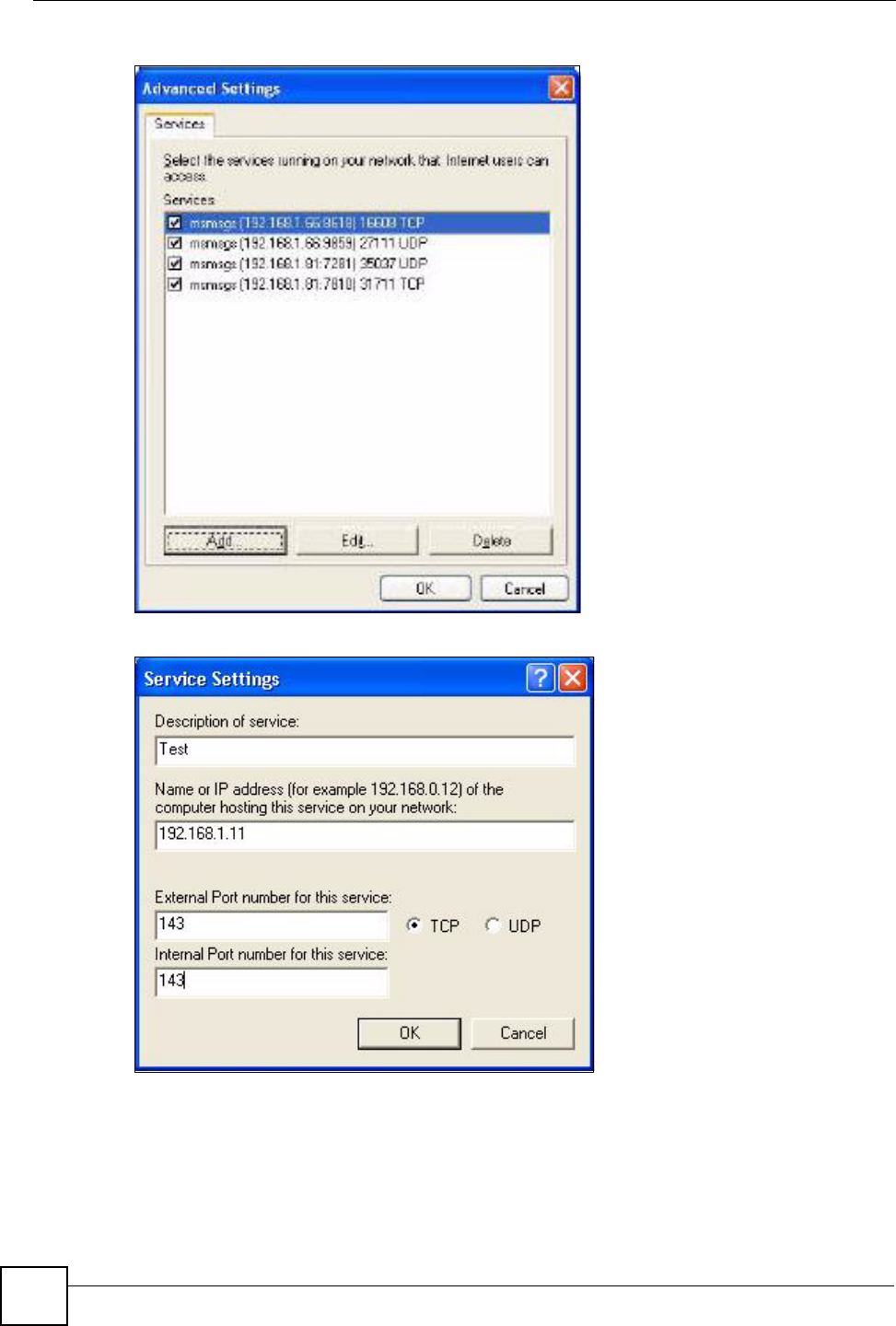
Chapter 17 Universal Plug-and-Play (UPnP)
NBG334W User’s Guide
166
Figure 95 Internet Connection Properties: Advanced Settings
Figure 96 Internet Connection Properties: Advanced Settings: Add
5When the UPnP-enabled device is disconnected from your computer, all port mappings
will be deleted automatically.
6Select Show icon in notification area when connected option and click OK. An icon
displays in the system tray.
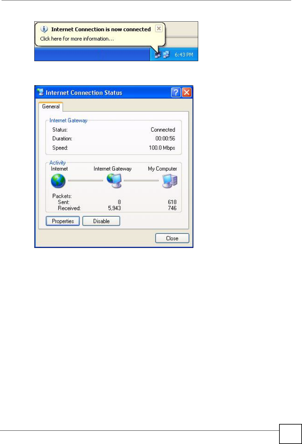
Chapter 17 Universal Plug-and-Play (UPnP)
NBG334W User’s Guide 167
Figure 97 System Tray Icon
7Double-click on the icon to display your current Internet connection status.
Figure 98 Internet Connection Status
Web Configurator Easy Access
With UPnP, you can access the web-based configurator on the NBG334W without finding out
the IP address of the NBG334W first. This comes helpful if you do not know the IP address of
the NBG334W.
Follow the steps below to access the web configurator.
1Click Start and then Control Panel.
2Double-click Network Connections.
3Select My Network Places under Other Places.
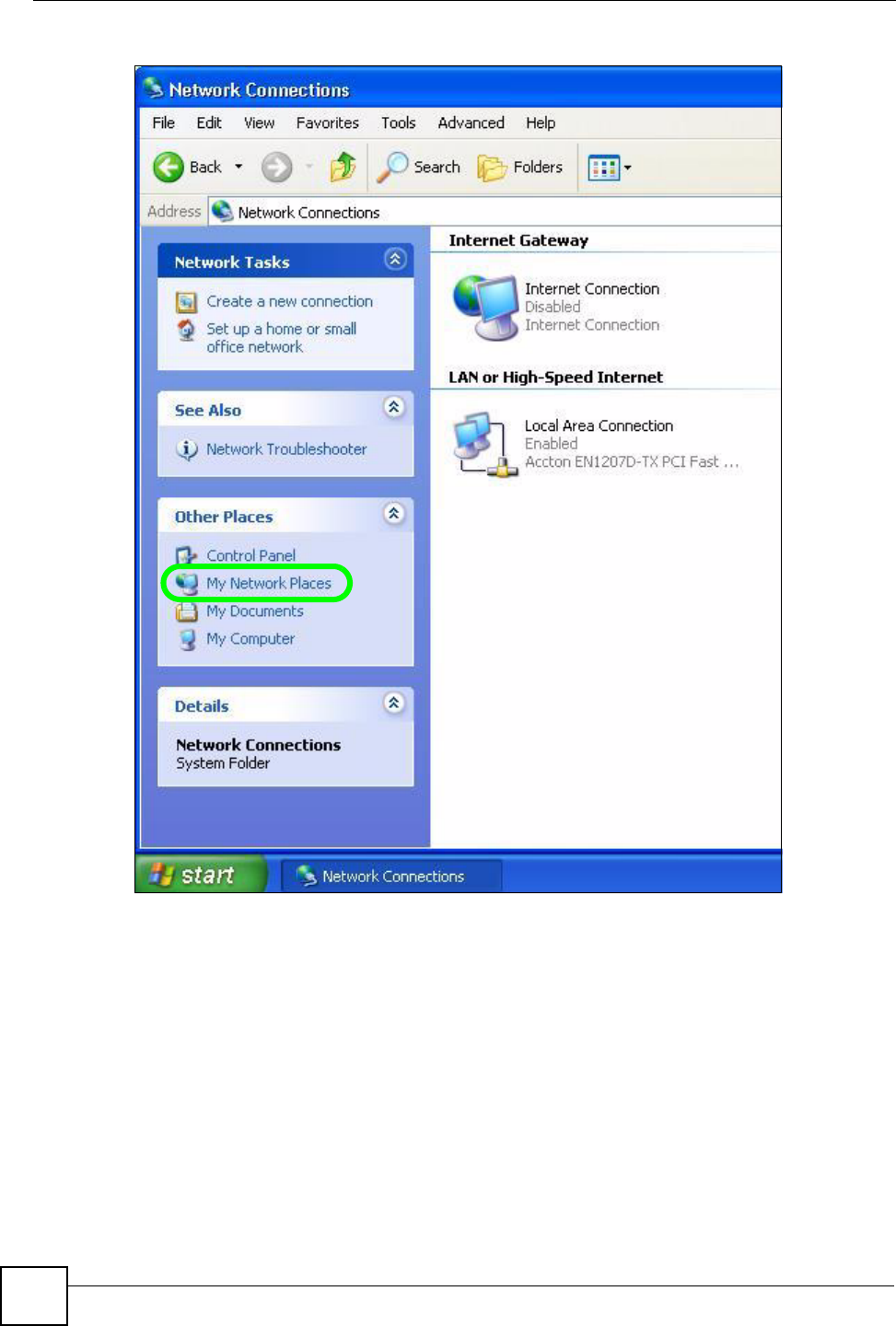
Chapter 17 Universal Plug-and-Play (UPnP)
NBG334W User’s Guide
168
Figure 99 Network Connections
4An icon with the description for each UPnP-enabled device displays under Local
Network.
5Right-click on the icon for your NBG334W and select Invoke. The web configurator
login screen displays.
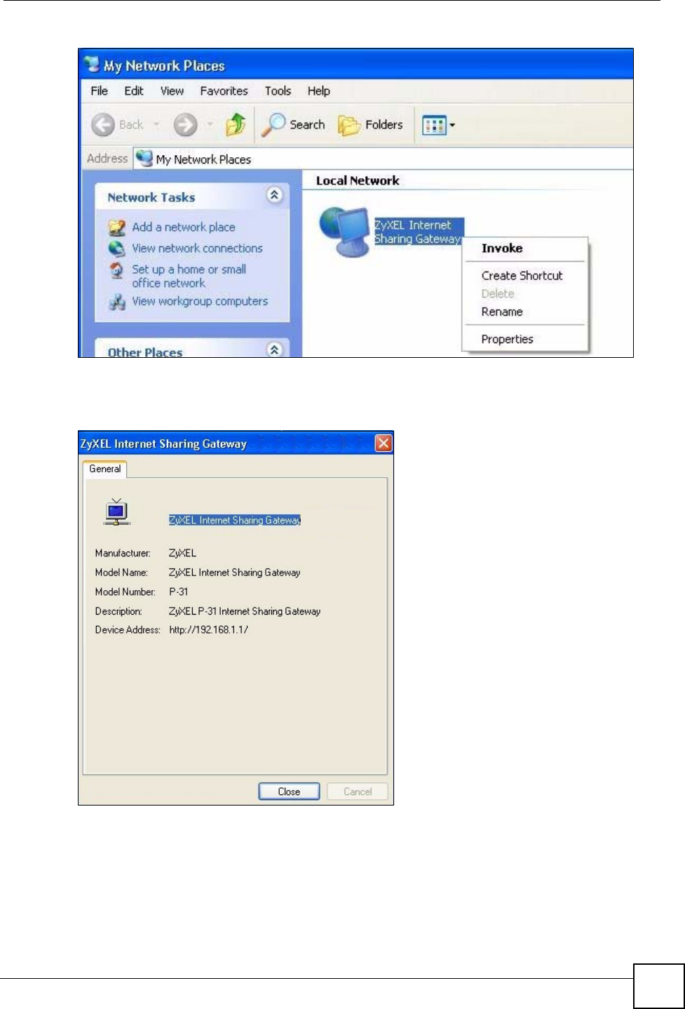
Chapter 17 Universal Plug-and-Play (UPnP)
NBG334W User’s Guide 169
Figure 100 Network Connections: My Network Places
6Right-click on the icon for your NBG334W and select Properties. A properties window
displays with basic information about the NBG334W.
Figure 101 Network Connections: My Network Places: Properties: Example

Chapter 17 Universal Plug-and-Play (UPnP)
NBG334W User’s Guide
170

171
PART V
Maintenance and
Troubleshooting
System (173)
Logs (177)
Tools (191)
Configuration Mode (197)
Sys Op Mode (199)
Troubleshooting (203)

172
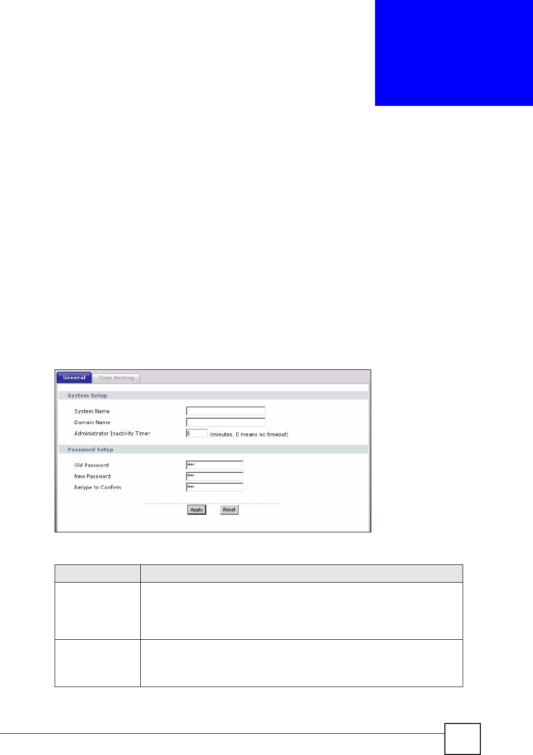
NBG334W User’s Guide 173
CHAPTER 18
System
This chapter provides information on the System screens.
18.1 System Overview
See the chapter about wizard setup for more information on the next few screens.
18.2 System General Screen
Click Maintenance > System. The following screen displays.
Figure 102 Maintenance > System > General
The following table describes the labels in this screen.
Table 69 Maintenance > System > General
LABEL DESCRIPTION
System Name System Name is a unique name to identify the NBG334W in an Ethernet
network. It is recommended you enter your computer’s “Computer name” in this
field (see the chapter about wizard setup for how to find your computer’s name).
This name can be up to 30 alphanumeric characters long. Spaces are not
allowed, but dashes “-” and underscores "_" are accepted.
Domain Name Enter the domain name (if you know it) here. If you leave this field blank, the ISP
may assign a domain name via DHCP.
The domain name entered by you is given priority over the ISP assigned domain
name.
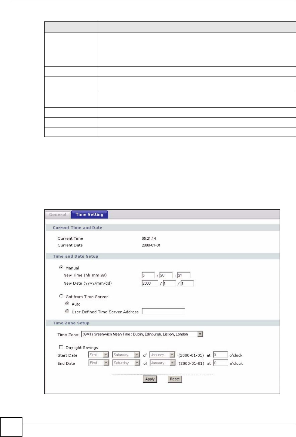
Chapter 18 System
NBG334W User’s Guide
174
18.3 Time Setting Screen
To change your NBG334W’s time and date, click Maintenance > System > Time Setting.
The screen appears as shown. Use this screen to configure the NBG334W’s time based on
your local time zone.
Figure 103 Maintenance > System > Time Setting
Administrator
Inactivity Timer
Type how many minutes a management session can be left idle before the
session times out. The default is 5 minutes. After it times out you have to log in
with your password again. Very long idle timeouts may have security risks. A
value of "0" means a management session never times out, no matter how long it
has been left idle (not recommended).
Password Setup Change your NBG334W’s password (recommended) using the fields as shown.
Old Password Type the default password or the existing password you use to access the
system in this field.
New Password Type your new system password (up to 30 characters). Note that as you type a
password, the screen displays an asterisk (*) for each character you type.
Retype to Confirm Type the new password again in this field.
Apply Click Apply to save your changes back to the NBG334W.
Reset Click Reset to begin configuring this screen afresh.
Table 69 Maintenance > System > General
LABEL DESCRIPTION

Chapter 18 System
NBG334W User’s Guide 175
The following table describes the labels in this screen.
Table 70 Maintenance > System > Time Setting
LABEL DESCRIPTION
Current Time and
Date
Current Time This field displays the time of your NBG334W.
Each time you reload this page, the NBG334W synchronizes the time with the
time server.
Current Date This field displays the date of your NBG334W.
Each time you reload this page, the NBG334W synchronizes the date with the
time server.
Time and Date
Setup
Manual Select this radio button to enter the time and date manually. If you configure a
new time and date, Time Zone and Daylight Saving at the same time, the new
time and date you entered has priority and the Time Zone and Daylight Saving
settings do not affect it.
New Time
(hh:mm:ss)
This field displays the last updated time from the time server or the last time
configured manually.
When you set Time and Date Setup to Manual, enter the new time in this field
and then click Apply.
New Date
(yyyy/mm/dd)
This field displays the last updated date from the time server or the last date
configured manually.
When you set Time and Date Setup to Manual, enter the new date in this field
and then click Apply.
Get from Time
Server
Select this radio button to have the NBG334W get the time and date from the
time server you specified below.
Auto Select Auto to have the NBG334W automatically search for an available time
server and synchronize the date and time with the time server after you click
Apply.
User Defined Time
Server Address
Select User Defined Time Server Address and enter the IP address or URL
(up to 20 extended ASCII characters in length) of your time server. Check with
your ISP/network administrator if you are unsure of this information.
Time Zone Setup
Time Zone Choose the time zone of your location. This will set the time difference between
your time zone and Greenwich Mean Time (GMT).
Daylight Savings Daylight saving is a period from late spring to early fall when many countries set
their clocks ahead of normal local time by one hour to give more daytime light in
the evening.
Select this option if you use Daylight Saving Time.
Start Date Configure the day and time when Daylight Saving Time starts if you selected
Daylight Savings. The o'clock field uses the 24 hour format. Here are a
couple of examples:
Daylight Saving Time starts in most parts of the United States on the first
Sunday of April. Each time zone in the United States starts using Daylight
Saving Time at 2 A.M. local time. So in the United States you would select
First, Sunday, April and type 2 in the o'clock field.
Daylight Saving Time starts in the European Union on the last Sunday of March.
All of the time zones in the European Union start using Daylight Saving Time at
the same moment (1 A.M. GMT or UTC). So in the European Union you would
select Last, Sunday, March. The time you type in the o'clock field depends on
your time zone. In Germany for instance, you would type 2 because Germany's
time zone is one hour ahead of GMT or UTC (GMT+1).

Chapter 18 System
NBG334W User’s Guide
176
End Date Configure the day and time when Daylight Saving Time ends if you selected
Daylight Savings. The o'clock field uses the 24 hour format. Here are a
couple of examples:
Daylight Saving Time ends in the United States on the last Sunday of October.
Each time zone in the United States stops using Daylight Saving Time at 2 A.M.
local time. So in the United States you would select Last, Sunday, October
and type 2 in the o'clock field.
Daylight Saving Time ends in the European Union on the last Sunday of
October. All of the time zones in the European Union stop using Daylight Saving
Time at the same moment (1 A.M. GMT or UTC). So in the European Union you
would select Last, Sunday, October. The time you type in the o'clock field
depends on your time zone. In Germany for instance, you would type 2 because
Germany's time zone is one hour ahead of GMT or UTC (GMT+1).
Apply Click Apply to save your changes back to the NBG334W.
Reset Click Reset to begin configuring this screen afresh.
Table 70 Maintenance > System > Time Setting
LABEL DESCRIPTION
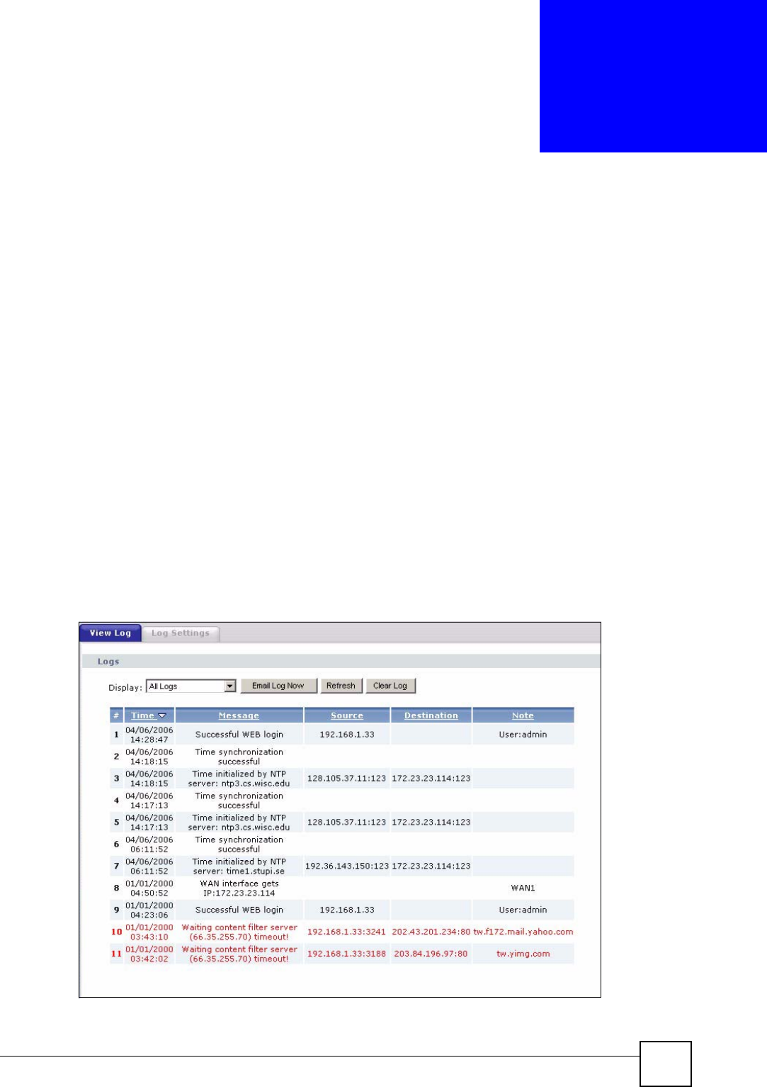
NBG334W User’s Guide 177
CHAPTER 19
Logs
This chapter contains information about configuring general log settings and viewing the
NBG334W’s logs. Refer to the appendices for example log message explanations.
19.1 View Log
The web configurator allows you to look at all of the NBG334W’s logs in one location.
Click Maintenance > Logs to open the View Log screen.
Use the View Log screen to see the logs for the categories that you selected in the Log
Settings screen (see Section 19.2 on page 178). Options include logs about system
maintenance, system errors, access control, allowed or blocked web sites, blocked web
features (such as ActiveX controls, Java and cookies), attacks (such as DoS) and IPSec.
Log entries in red indicate system error logs. The log wraps around and deletes the old entries
after it fills. Click a column heading to sort the entries. A triangle indicates ascending or
descending sort order.
Figure 104 Maintenance > Logs > View Log
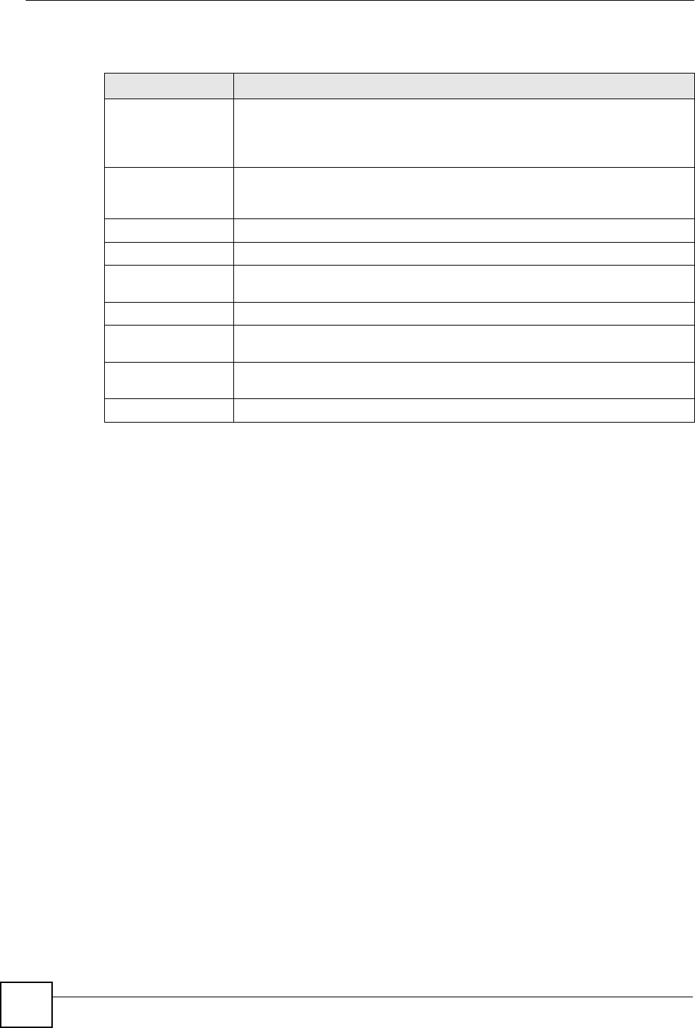
Chapter 19 Logs
NBG334W User’s Guide
178
The following table describes the labels in this screen.
19.2 Log Settings
You can configure the NBG334W’s general log settings in one location.
Click Maintenance > Logs > Log Settings to open the Log Settings screen.
Use the Log Settings screen to configure to where the NBG334W is to send logs; the schedule
for when the NBG334W is to send the logs and which logs and/or immediate alerts the
NBG334W to send.
An alert is a type of log that warrants more serious attention. They include system errors,
attacks (access control) and attempted access to blocked web sites or web sites with restricted
web features such as cookies, active X and so on. Some categories such as System Errors
consist of both logs and alerts. You may differentiate them by their color in the View Log
screen. Alerts display in red and logs display in black.
Alerts are e-mailed as soon as they happen. Logs may be e-mailed as soon as the log is full
(see Log Schedule). Selecting many alert and/or log categories (especially Access Control)
may result in many e-mails being sent.
Table 71 Maintenance > Logs > View Log
LABEL DESCRIPTION
Display The categories that you select in the Log Settings page (see Section 19.2 on
page 178) display in the drop-down list box.
Select a category of logs to view; select All Logs to view logs from all of the log
categories that you selected in the Log Settings page.
Email Log Now Click Email Log Now to send the log screen to the e-mail address specified in
the Log Settings page (make sure that you have first filled in the Address Info
fields in Log Settings).
Refresh Click Refresh to renew the log screen.
Clear Log Click Clear Log to delete all the logs.
Time This field displays the time the log was recorded. See the chapter on system
maintenance and information to configure the NBG334W’s time and date.
Message This field states the reason for the log.
Source This field lists the source IP address and the port number of the incoming
packet.
Destination This field lists the destination IP address and the port number of the incoming
packet.
Note This field displays additional information about the log entry.
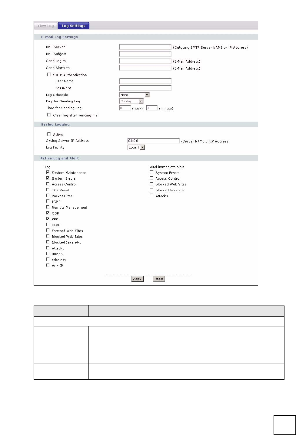
Chapter 19 Logs
NBG334W User’s Guide 179
Figure 105 Maintenance > Logs > Log Settings
The following table describes the labels in this screen.
Table 72 Maintenance > Logs > Log Settings
LABEL DESCRIPTION
E-mail Log Settings
Mail Server Enter the server name or the IP address of the mail server for the e-mail
addresses specified below. If this field is left blank, logs and alert messages will
not be sent via E-mail.
Mail Subject Type a title that you want to be in the subject line of the log e-mail message that
the NBG334W sends. Not all NBG334W models have this field.
Send Log To The NBG334W sends logs to the e-mail address specified in this field. If this
field is left blank, the NBG334W does not send logs via e-mail.

Chapter 19 Logs
NBG334W User’s Guide
180
Send Alerts To Alerts are real-time notifications that are sent as soon as an event, such as a
DoS attack, system error, or forbidden web access attempt occurs. Enter the E-
mail address where the alert messages will be sent. Alerts include system
errors, attacks and attempted access to blocked web sites. If this field is left
blank, alert messages will not be sent via E-mail.
SMTP
Authentication
SMTP (Simple Mail Transfer Protocol) is the message-exchange standard for
the Internet. SMTP enables you to move messages from one e-mail server to
another.
Select the check box to activate SMTP authentication. If mail server
authentication is needed but this feature is disabled, you will not receive the e-
mail logs.
User Name Enter the user name (up to 31 characters) (usually the user name of a mail
account).
Password Enter the password associated with the user name above.
Log Schedule This drop-down menu is used to configure the frequency of log messages being
sent as E-mail:
•Daily
• Weekly
• Hourly
• When Log is Full
• None.
If you select Weekly or Daily, specify a time of day when the E-mail should be
sent. If you select Weekly, then also specify which day of the week the E-mail
should be sent. If you select When Log is Full, an alert is sent when the log fills
up. If you select None, no log messages are sent.
Day for Sending Log Use the drop down list box to select which day of the week to send the logs.
Time for Sending
Log
Enter the time of the day in 24-hour format (for example 23:00 equals 11:00 pm)
to send the logs.
Clear log after
sending mail
Select the checkbox to delete all the logs after the NBG334W sends an E-mail
of the logs.
Syslog Logging The NBG334W sends a log to an external syslog server.
Active Click Active to enable syslog logging.
Syslog Server IP
Address
Enter the server name or IP address of the syslog server that will log the
selected categories of logs.
Log Facility Select a location from the drop down list box. The log facility allows you to log
the messages to different files in the syslog server. Refer to the syslog server
manual for more information.
Active Log and Alert
Log Select the categories of logs that you want to record.
Send Immediate
Alert
Select log categories for which you want the NBG334W to send E-mail alerts
immediately.
Apply Click Apply to save your changes.
Reset Click Reset to begin configuring this screen afresh.
Table 72 Maintenance > Logs > Log Settings
LABEL DESCRIPTION

Chapter 19 Logs
NBG334W User’s Guide 181
19.3 Log Descriptions
This section provides descriptions of example log messages.
Table 73 System Maintenance Logs
LOG MESSAGE DESCRIPTION
Time calibration is
successful
The router has adjusted its time based on information from
the time server.
Time calibration failed The router failed to get information from the time server.
WAN interface gets IP:%s A WAN interface got a new IP address from the DHCP,
PPPoE, PPTP or dial-up server.
DHCP client IP expired A DHCP client's IP address has expired.
DHCP server assigns%s The DHCP server assigned an IP address to a client.
Successful WEB login Someone has logged on to the router's web configurator
interface.
WEB login failed Someone has failed to log on to the router's web configurator
interface.
Successful TELNET login Someone has logged on to the router via telnet.
TELNET login failed Someone has failed to log on to the router via telnet.
Successful FTP login Someone has logged on to the router via ftp.
FTP login failed Someone has failed to log on to the router via ftp.
NAT Session Table is Full! The maximum number of NAT session table entries has been
exceeded and the table is full.
Starting Connectivity
Monitor
Starting Connectivity Monitor.
Time initialized by Daytime
Server
The router got the time and date from the Daytime server.
Time initialized by Time
server
The router got the time and date from the time server.
Time initialized by NTP
server
The router got the time and date from the NTP server.
Connect to Daytime server
fail
The router was not able to connect to the Daytime server.
Connect to Time server fail The router was not able to connect to the Time server.
Connect to NTP server fail The router was not able to connect to the NTP server.
Too large ICMP packet has
been dropped
The router dropped an ICMP packet that was too large.
Configuration Change: PC =
0x%x, Task ID = 0x%x
The router is saving configuration changes.
Successful SSH login Someone has logged on to the router’s SSH server.
SSH login failed Someone has failed to log on to the router’s SSH server.
Successful HTTPS login Someone has logged on to the router's web configurator
interface using HTTPS protocol.
HTTPS login failed Someone has failed to log on to the router's web configurator
interface using HTTPS protocol.
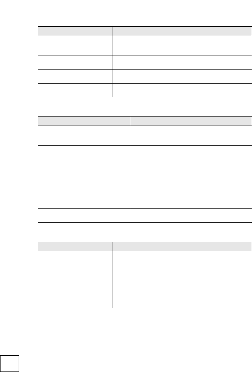
Chapter 19 Logs
NBG334W User’s Guide
182
Table 74 System Error Logs
LOG MESSAGE DESCRIPTION
%s exceeds the max.
number of session per
host!
This attempt to create a NAT session exceeds the maximum
number of NAT session table entries allowed to be created per
host.
setNetBIOSFilter: calloc
error
The router failed to allocate memory for the NetBIOS filter
settings.
readNetBIOSFilter: calloc
error
The router failed to allocate memory for the NetBIOS filter
settings.
WAN connection is down. A WAN connection is down. You cannot access the network
through this interface.
Table 75 Access Control Logs
LOG MESSAGE DESCRIPTION
Firewall default policy: [TCP |
UDP | IGMP | ESP | GRE | OSPF]
<Packet Direction>
Attempted TCP/UDP/IGMP/ESP/GRE/OSPF access
matched the default policy and was blocked or forwarded
according to the default policy’s setting.
Firewall rule [NOT] match:[TCP |
UDP | IGMP | ESP | GRE | OSPF]
<Packet Direction>, <rule:%d>
Attempted TCP/UDP/IGMP/ESP/GRE/OSPF access
matched (or did not match) a configured firewall rule
(denoted by its number) and was blocked or forwarded
according to the rule.
Triangle route packet forwarded:
[TCP | UDP | IGMP | ESP | GRE |
OSPF]
The firewall allowed a triangle route session to pass
through.
Packet without a NAT table entry
blocked: [TCP | UDP | IGMP | ESP
| GRE | OSPF]
The router blocked a packet that didn't have a
corresponding NAT table entry.
Router sent blocked web site
message: TCP
The router sent a message to notify a user that the router
blocked access to a web site that the user requested.
Table 76 TCP Reset Logs
LOG MESSAGE DESCRIPTION
Under SYN flood attack,
sent TCP RST
The router sent a TCP reset packet when a host was under a SYN
flood attack (the TCP incomplete count is per destination host.)
Exceed TCP MAX
incomplete, sent TCP RST
The router sent a TCP reset packet when the number of TCP
incomplete connections exceeded the user configured threshold.
(the TCP incomplete count is per destination host.) Note: Refer to
TCP Maximum Incomplete in the Firewall Attack Alerts screen.
Peer TCP state out of
order, sent TCP RST
The router sent a TCP reset packet when a TCP connection state
was out of order.Note: The firewall refers to RFC793 Figure 6 to
check the TCP state.
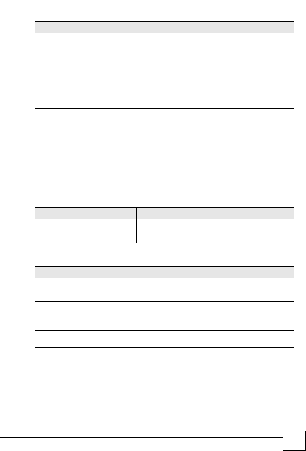
Chapter 19 Logs
NBG334W User’s Guide 183
Firewall session time
out, sent TCP RST
The router sent a TCP reset packet when a dynamic firewall
session timed out.
The default timeout values are as follows:
ICMP idle timeout: 3 minutes
UDP idle timeout: 3 minutes
TCP connection (three way handshaking) timeout: 270 seconds
TCP FIN-wait timeout: 2 MSL (Maximum Segment Lifetime set in
the TCP header).
TCP idle (established) timeout (s): 150 minutes
TCP reset timeout: 10 seconds
Exceed MAX incomplete,
sent TCP RST
The router sent a TCP reset packet when the number of
incomplete connections (TCP and UDP) exceeded the user-
configured threshold. (Incomplete count is for all TCP and UDP
connections through the firewall.)Note: When the number of
incomplete connections (TCP + UDP) > “Maximum Incomplete
High”, the router sends TCP RST packets for TCP connections
and destroys TOS (firewall dynamic sessions) until incomplete
connections < “Maximum Incomplete Low”.
Access block, sent TCP
RST
The router sends a TCP RST packet and generates this log if you
turn on the firewall TCP reset mechanism (via CI command: "sys
firewall tcprst").
Table 77 Packet Filter Logs
LOG MESSAGE DESCRIPTION
[TCP | UDP | ICMP | IGMP |
Generic] packet filter
matched (set:%d, rule:%d)
Attempted access matched a configured filter rule (denoted
by its set and rule number) and was blocked or forwarded
according to the rule.
Table 78 ICMP Logs
LOG MESSAGE DESCRIPTION
Firewall default policy: ICMP
<Packet Direction>, <type:%d>,
<code:%d>
ICMP access matched the default policy and was
blocked or forwarded according to the user's setting. For
type and code details, see Table 87 on page 188.
Firewall rule [NOT] match: ICMP
<Packet Direction>, <rule:%d>,
<type:%d>, <code:%d>
ICMP access matched (or didn’t match) a firewall rule
(denoted by its number) and was blocked or forwarded
according to the rule. For type and code details, see
Table 87 on page 188.
Triangle route packet forwarded:
ICMP
The firewall allowed a triangle route session to pass
through.
Packet without a NAT table entry
blocked: ICMP
The router blocked a packet that didn’t have a
corresponding NAT table entry.
Unsupported/out-of-order ICMP:
ICMP
The firewall does not support this kind of ICMP packets
or the ICMP packets are out of order.
Router reply ICMP packet: ICMP The router sent an ICMP reply packet to the sender.
Table 76 TCP Reset Logs (continued)
LOG MESSAGE DESCRIPTION
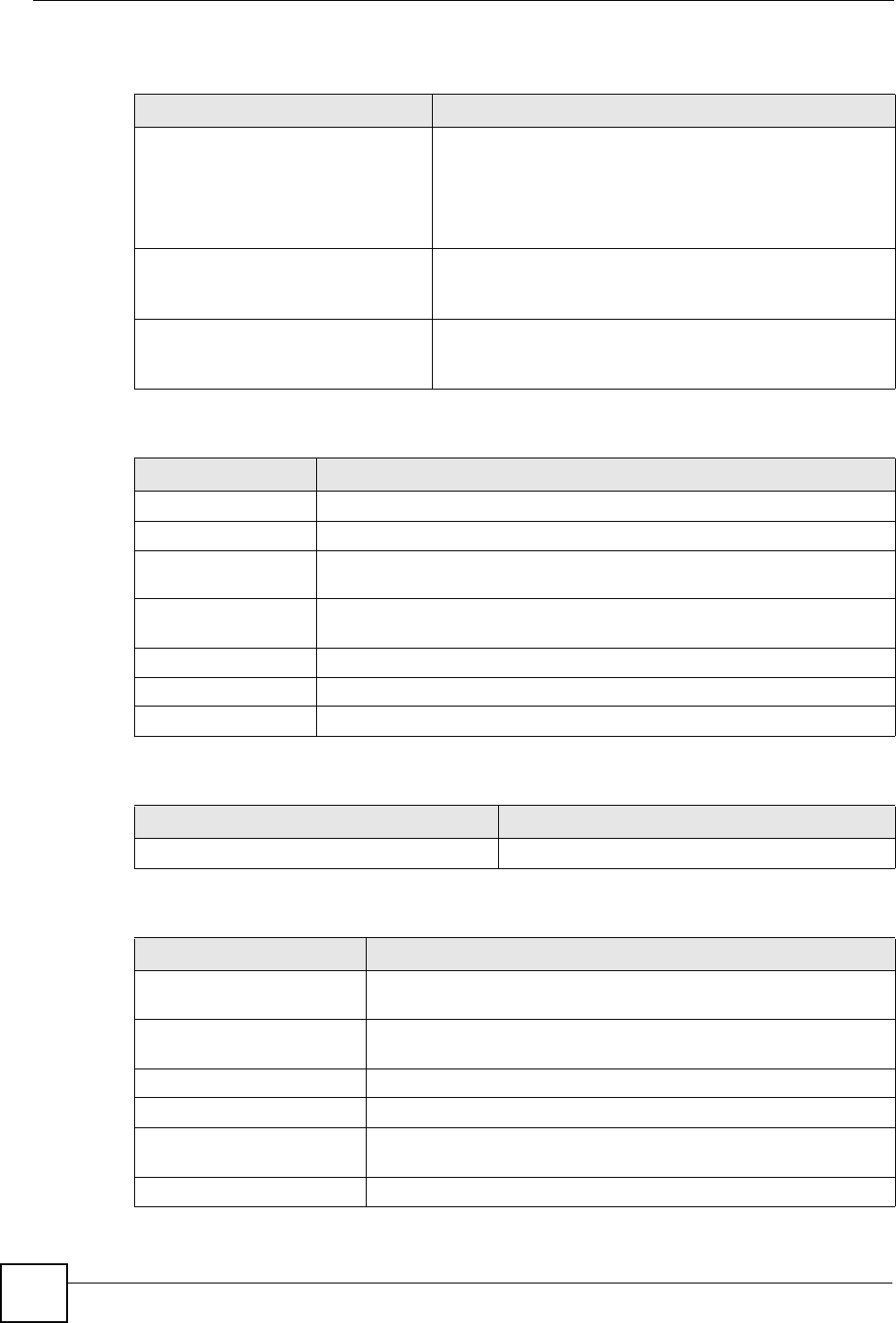
Chapter 19 Logs
NBG334W User’s Guide
184
Table 79 CDR Logs
LOG MESSAGE DESCRIPTION
board%d line%d channel%d,
call%d,%s C01 Outgoing Call
dev=%x ch=%x%s
The router received the setup requirements for a call. “call” is
the reference (count) number of the call. “dev” is the device
type (3 is for dial-up, 6 is for PPPoE, 10 is for PPTP).
"channel" or “ch” is the call channel ID.For example,"board 0
line 0 channel 0, call 3, C01 Outgoing Call dev=6 ch=0
"Means the router has dialed to the PPPoE server 3 times.
board%d line%d channel%d,
call%d,%s C02 OutCall
Connected%d%s
The PPPoE, PPTP or dial-up call is connected.
board%d line%d channel%d,
call%d,%s C02 Call
Terminated
The PPPoE, PPTP or dial-up call was disconnected.
Table 80 PPP Logs
LOG MESSAGE DESCRIPTION
ppp:LCP Starting The PPP connection’s Link Control Protocol stage has started.
ppp:LCP Opening The PPP connection’s Link Control Protocol stage is opening.
ppp:CHAP Opening The PPP connection’s Challenge Handshake Authentication Protocol stage is
opening.
ppp:IPCP
Starting
The PPP connection’s Internet Protocol Control Protocol stage is starting.
ppp:IPCP Opening The PPP connection’s Internet Protocol Control Protocol stage is opening.
ppp:LCP Closing The PPP connection’s Link Control Protocol stage is closing.
ppp:IPCP Closing The PPP connection’s Internet Protocol Control Protocol stage is closing.
Table 81 UPnP Logs
LOG MESSAGE DESCRIPTION
UPnP pass through Firewall UPnP packets can pass through the firewall.
Table 82 Content Filtering Logs
LOG MESSAGE DESCRIPTION
%s: Keyword blocking The content of a requested web page matched a user defined
keyword.
%s: Not in trusted web
list
The web site is not in a trusted domain, and the router blocks all traffic
except trusted domain sites.
%s: Forbidden Web site The web site is in the forbidden web site list.
%s: Contains ActiveX The web site contains ActiveX.
%s: Contains Java
applet
The web site contains a Java applet.
%s: Contains cookie The web site contains a cookie.
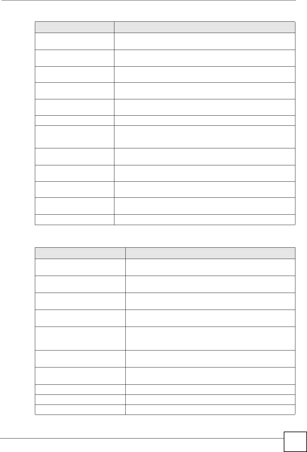
Chapter 19 Logs
NBG334W User’s Guide 185
%s: Proxy mode
detected
The router detected proxy mode in the packet.
%s The content filter server responded that the web site is in the blocked
category list, but it did not return the category type.
%s:%s The content filter server responded that the web site is in the blocked
category list, and returned the category type.
%s(cache hit) The system detected that the web site is in the blocked list from the
local cache, but does not know the category type.
%s:%s(cache hit) The system detected that the web site is in blocked list from the local
cache, and knows the category type.
%s: Trusted Web site The web site is in a trusted domain.
%s When the content filter is not on according to the time schedule or you
didn't select the "Block Matched Web Site” check box, the system
forwards the web content.
Waiting content filter
server timeout
The external content filtering server did not respond within the timeout
period.
DNS resolving failed The NBG334W cannot get the IP address of the external content
filtering via DNS query.
Creating socket failed The NBG334W cannot issue a query because TCP/IP socket creation
failed, port:port number.
Connecting to content
filter server fail
The connection to the external content filtering server failed.
License key is invalid The external content filtering license key is invalid.
Table 83 Attack Logs
LOG MESSAGE DESCRIPTION
attack [TCP | UDP | IGMP
| ESP | GRE | OSPF]
The firewall detected a TCP/UDP/IGMP/ESP/GRE/OSPF attack.
attack ICMP (type:%d,
code:%d)
The firewall detected an ICMP attack. For type and code details,
see Table 87 on page 188.
land [TCP | UDP | IGMP |
ESP | GRE | OSPF]
The firewall detected a TCP/UDP/IGMP/ESP/GRE/OSPF land
attack.
land ICMP (type:%d,
code:%d)
The firewall detected an ICMP land attack. For type and code
details, see Table 87 on page 188.
ip spoofing - WAN [TCP |
UDP | IGMP | ESP | GRE |
OSPF]
The firewall detected an IP spoofing attack on the WAN port.
ip spoofing - WAN ICMP
(type:%d, code:%d)
The firewall detected an ICMP IP spoofing attack on the WAN
port. For type and code details, see Table 87 on page 188.
icmp echo: ICMP (type:%d,
code:%d)
The firewall detected an ICMP echo attack. For type and code
details, see Table 87 on page 188.
syn flood TCP The firewall detected a TCP syn flood attack.
ports scan TCP The firewall detected a TCP port scan attack.
teardrop TCP The firewall detected a TCP teardrop attack.
Table 82 Content Filtering Logs (continued)
LOG MESSAGE DESCRIPTION
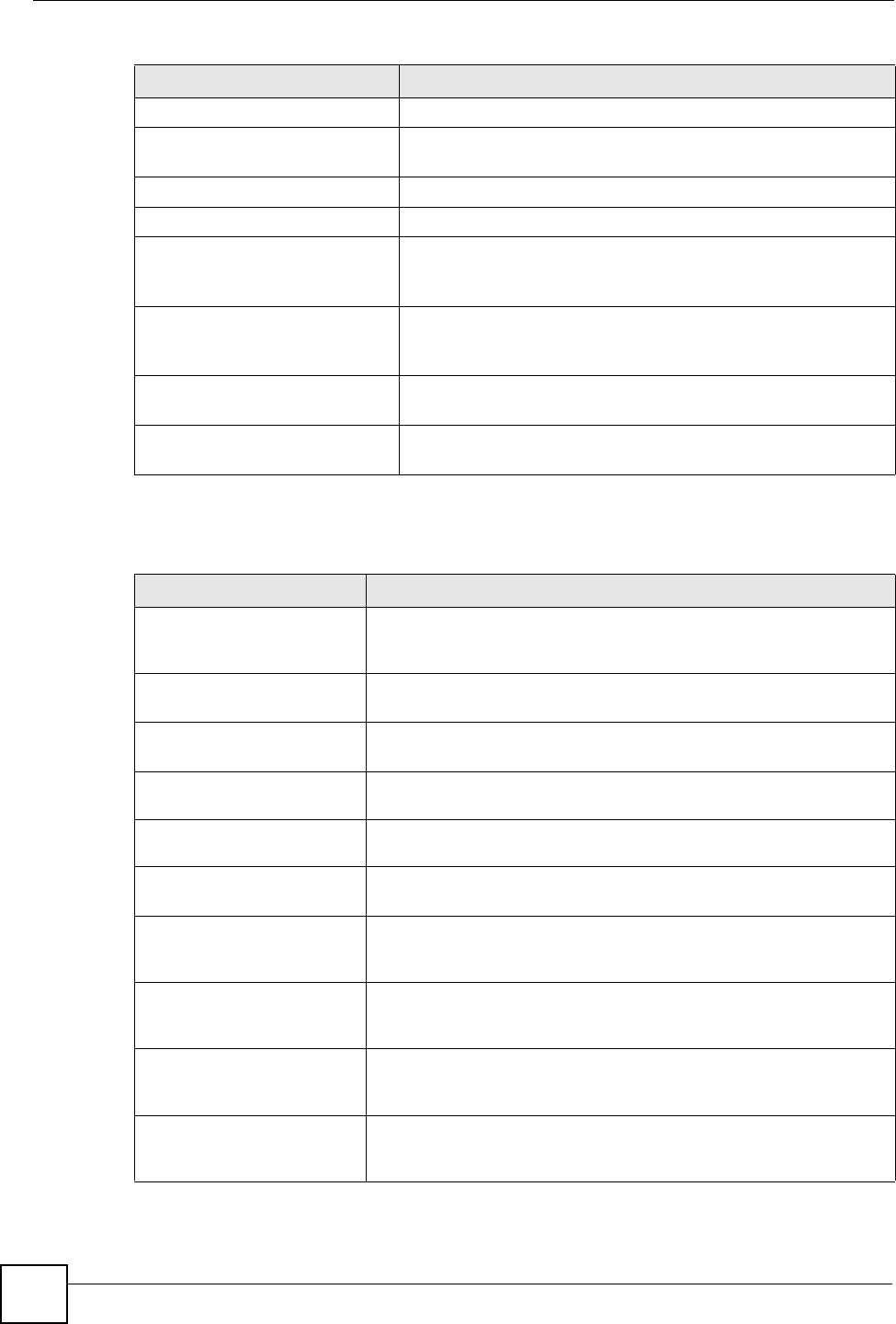
Chapter 19 Logs
NBG334W User’s Guide
186
teardrop UDP The firewall detected an UDP teardrop attack.
teardrop ICMP (type:%d,
code:%d)
The firewall detected an ICMP teardrop attack. For type and code
details, see Table 87 on page 188.
illegal command TCP The firewall detected a TCP illegal command attack.
NetBIOS TCP The firewall detected a TCP NetBIOS attack.
ip spoofing - no routing
entry [TCP | UDP | IGMP |
ESP | GRE | OSPF]
The firewall classified a packet with no source routing entry as an
IP spoofing attack.
ip spoofing - no routing
entry ICMP (type:%d,
code:%d)
The firewall classified an ICMP packet with no source routing
entry as an IP spoofing attack.
vulnerability ICMP
(type:%d, code:%d)
The firewall detected an ICMP vulnerability attack. For type and
code details, see Table 87 on page 188.
traceroute ICMP (type:%d,
code:%d)
The firewall detected an ICMP traceroute attack. For type and
code details, see Table 87 on page 188.
Table 84 PKI Logs
LOG MESSAGE DESCRIPTION
Enrollment successful The SCEP online certificate enrollment was successful. The
Destination field records the certification authority server IP address
and port.
Enrollment failed The SCEP online certificate enrollment failed. The Destination field
records the certification authority server’s IP address and port.
Failed to resolve
<SCEP CA server url>
The SCEP online certificate enrollment failed because the certification
authority server’s address cannot be resolved.
Enrollment successful The CMP online certificate enrollment was successful. The Destination
field records the certification authority server’s IP address and port.
Enrollment failed The CMP online certificate enrollment failed. The Destination field
records the certification authority server’s IP address and port.
Failed to resolve <CMP
CA server url>
The CMP online certificate enrollment failed because the certification
authority server’s IP address cannot be resolved.
Rcvd ca cert: <subject
name>
The router received a certification authority certificate, with subject
name as recorded, from the LDAP server whose IP address and port
are recorded in the Source field.
Rcvd user cert:
<subject name>
The router received a user certificate, with subject name as recorded,
from the LDAP server whose IP address and port are recorded in the
Source field.
Rcvd CRL <size>:
<issuer name>
The router received a CRL (Certificate Revocation List), with size and
issuer name as recorded, from the LDAP server whose IP address and
port are recorded in the Source field.
Rcvd ARL <size>:
<issuer name>
The router received an ARL (Authority Revocation List), with size and
issuer name as recorded, from the LDAP server whose address and
port are recorded in the Source field.
Table 83 Attack Logs (continued)
LOG MESSAGE DESCRIPTION

Chapter 19 Logs
NBG334W User’s Guide 187
Failed to decode the
received ca cert
The router received a corrupted certification authority certificate from
the LDAP server whose address and port are recorded in the Source
field.
Failed to decode the
received user cert
The router received a corrupted user certificate from the LDAP server
whose address and port are recorded in the Source field.
Failed to decode the
received CRL
The router received a corrupted CRL (Certificate Revocation List) from
the LDAP server whose address and port are recorded in the Source
field.
Failed to decode the
received ARL
The router received a corrupted ARL (Authority Revocation List) from
the LDAP server whose address and port are recorded in the Source
field.
Rcvd data <size> too
large! Max size
allowed: <max size>
The router received directory data that was too large (the size is listed)
from the LDAP server whose address and port are recorded in the
Source field. The maximum size of directory data that the router allows
is also recorded.
Cert trusted: <subject
name>
The router has verified the path of the certificate with the listed subject
name.
Due to <reason codes>,
cert not trusted:
<subject name>
Due to the reasons listed, the certificate with the listed subject name
has not passed the path verification. The recorded reason codes are
only approximate reasons for not trusting the certificate. Please see
Table 87 on page 188 for the corresponding descriptions of the codes.
Table 85 802.1X Logs
LOG MESSAGE DESCRIPTION
Local User Database accepts
user.
A user was authenticated by the local user database.
Local User Database reports user
credential error.
A user was not authenticated by the local user database
because of an incorrect user password.
Local User Database does not
find user`s credential.
A user was not authenticated by the local user database
because the user is not listed in the local user database.
RADIUS accepts user. A user was authenticated by the RADIUS Server.
RADIUS rejects user. Pls check
RADIUS Server.
A user was not authenticated by the RADIUS Server.
Please check the RADIUS Server.
Local User Database does not
support authentication method.
The local user database only supports the EAP-MD5
method. A user tried to use another authentication
method and was not authenticated.
User logout because of session
timeout expired.
The router logged out a user whose session expired.
User logout because of user
deassociation.
The router logged out a user who ended the session.
User logout because of no
authentication response from
user.
The router logged out a user from which there was no
authentication response.
User logout because of idle
timeout expired.
The router logged out a user whose idle timeout period
expired.
User logout because of user
request.
A user logged out.
Table 84 PKI Logs (continued)
LOG MESSAGE DESCRIPTION
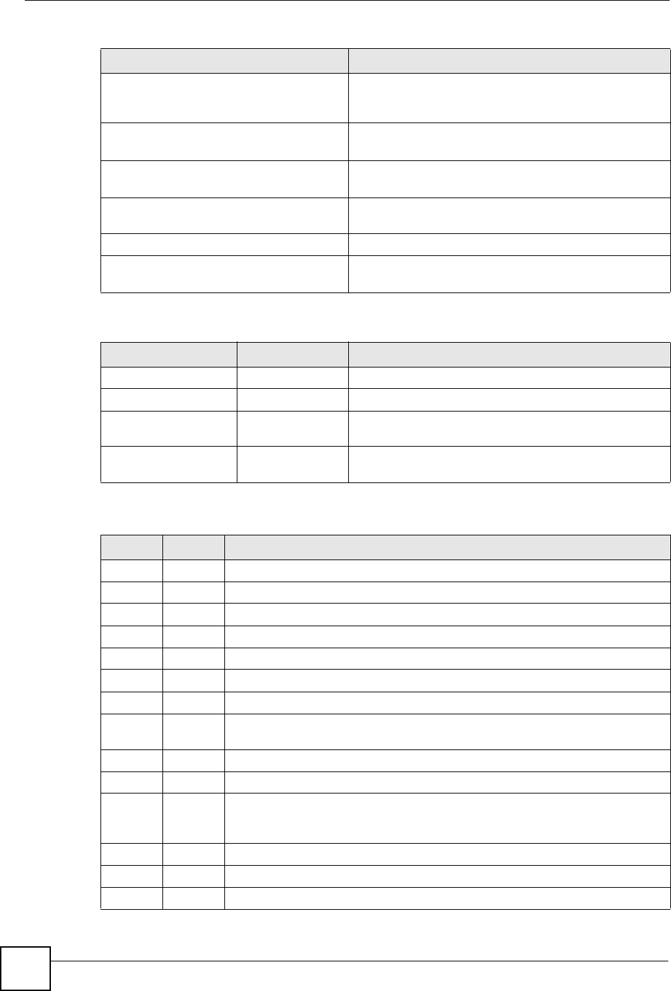
Chapter 19 Logs
NBG334W User’s Guide
188
Local User Database does not
support authentication method.
A user tried to use an authentication method that the
local user database does not support (it only supports
EAP-MD5).
No response from RADIUS. Pls
check RADIUS Server.
There is no response message from the RADIUS server,
please check the RADIUS server.
Use Local User Database to
authenticate user.
The local user database is operating as the
authentication server.
Use RADIUS to authenticate user. The RADIUS server is operating as the authentication
server.
No Server to authenticate user. There is no authentication server to authenticate a user.
Local User Database does not
find user`s credential.
A user was not authenticated by the local user database
because the user is not listed in the local user database.
Table 86 ACL Setting Notes
PACKET DIRECTION DIRECTION DESCRIPTION
(L to W) LAN to WAN ACL set for packets traveling from the LAN to the WAN.
(W to L) WAN to LAN ACL set for packets traveling from the WAN to the LAN.
(L to L/P) LAN to LAN/
NBG334W
ACL set for packets traveling from the LAN to the LAN or
the NBG334W.
(W to W/P) WAN to WAN/
NBG334W
ACL set for packets traveling from the WAN to the WAN
or the NBG334W.
Table 87 ICMP Notes
TYPE CODE DESCRIPTION
0Echo Reply
0Echo reply message
3Destination Unreachable
0Net unreachable
1Host unreachable
2Protocol unreachable
3Port unreachable
4A packet that needed fragmentation was dropped because it was set to Don't
Fragment (DF)
5Source route failed
4Source Quench
0A gateway may discard internet datagrams if it does not have the buffer space
needed to queue the datagrams for output to the next network on the route to
the destination network.
5Redirect
0Redirect datagrams for the Network
1Redirect datagrams for the Host
Table 85 802.1X Logs (continued)
LOG MESSAGE DESCRIPTION

Chapter 19 Logs
NBG334W User’s Guide 189
The following table shows RFC-2408 ISAKMP payload types that the log displays. Please
refer to the RFC for detailed information on each type.
2Redirect datagrams for the Type of Service and Network
3Redirect datagrams for the Type of Service and Host
8Echo
0Echo message
11 Time Exceeded
0Time to live exceeded in transit
1Fragment reassembly time exceeded
12 Parameter Problem
0Pointer indicates the error
13 Timestamp
0Timestamp request message
14 Timestamp Reply
0Timestamp reply message
15 Information Request
0Information request message
16 Information Reply
0Information reply message
Table 88 Syslog Logs
LOG MESSAGE DESCRIPTION
<Facility*8 + Severity>Mon dd
hr:mm:ss hostname
src="<srcIP:srcPort>"
dst="<dstIP:dstPort>"
msg="<msg>" note="<note>"
devID="<mac address last three
numbers>" cat="<category>
"This message is sent by the system ("RAS" displays as
the system name if you haven’t configured one) when the
router generates a syslog. The facility is defined in the web
MAIN MENU->LOGS->Log Settings page. The severity is
the log’s syslog class. The definition of messages and
notes are defined in the various log charts throughout this
appendix. The “devID” is the last three characters of the
MAC address of the router’s LAN port. The “cat” is the
same as the category in the router’s logs.
Table 89 RFC-2408 ISAKMP Payload Types
LOG DISPLAY PAYLOAD TYPE
SA Security Association
PROP Proposal
TRANS Transform
KE Key Exchange
ID Identification
CER Certificate
CER_REQ Certificate Request
HASH Hash
Table 87 ICMP Notes (continued)
TYPE CODE DESCRIPTION