ZyXEL Communications NBG334W Wireless Firewall Router User Manual NBG334W User s Guide
ZyXEL Communications Corporation Wireless Firewall Router NBG334W User s Guide
Contents
- 1. Users Manual Part 1
- 2. Users Manual Part 2
- 3. Users Manual Part 3
- 4. Users Manual Part 4
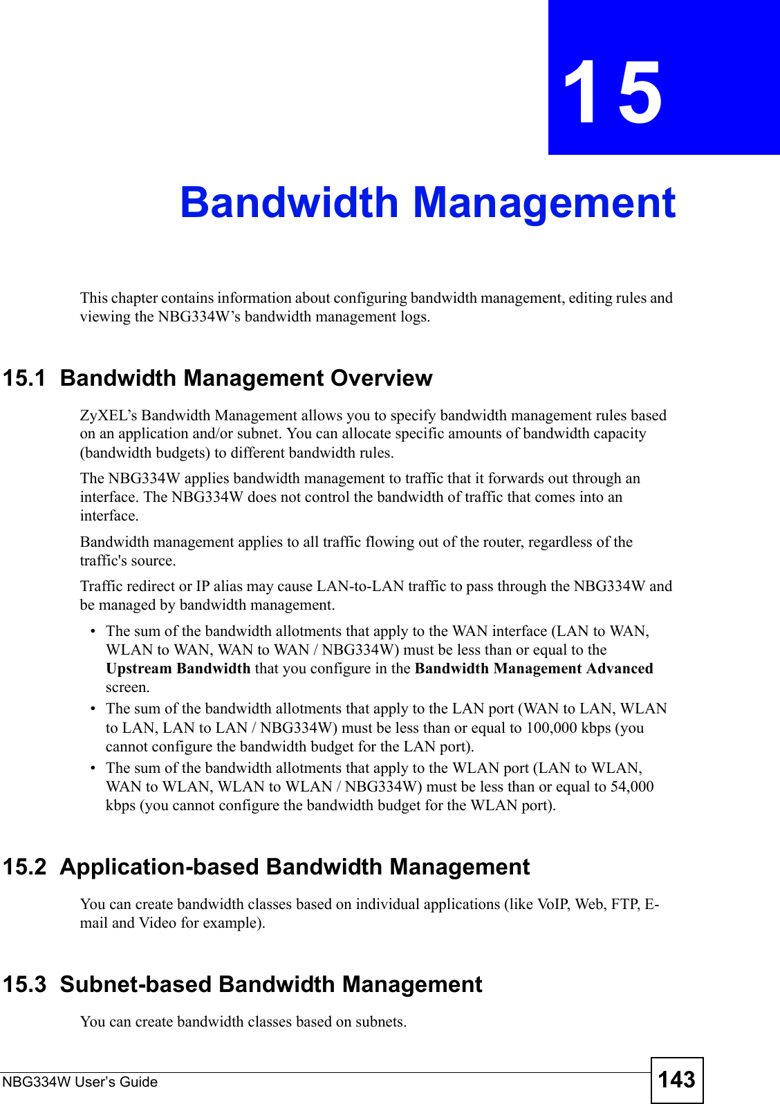
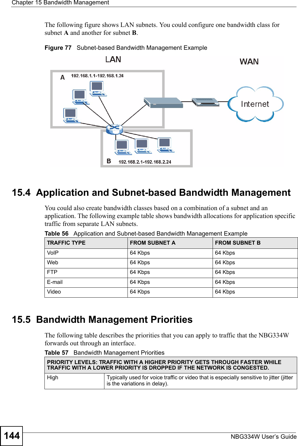
Users Manual Part 3
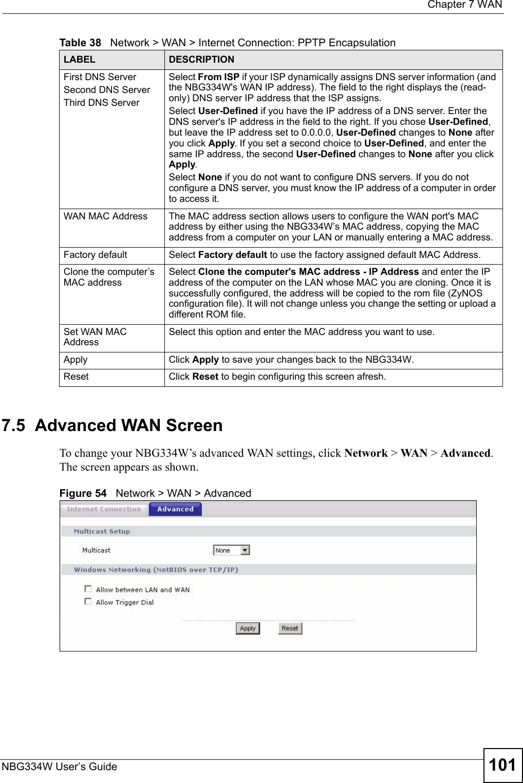
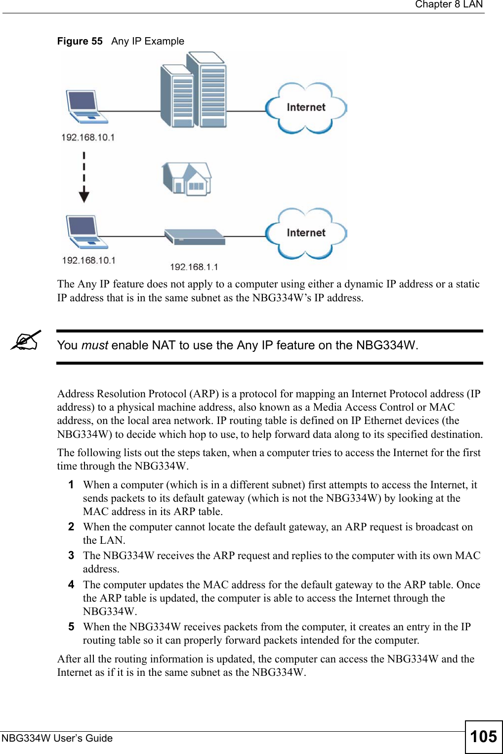

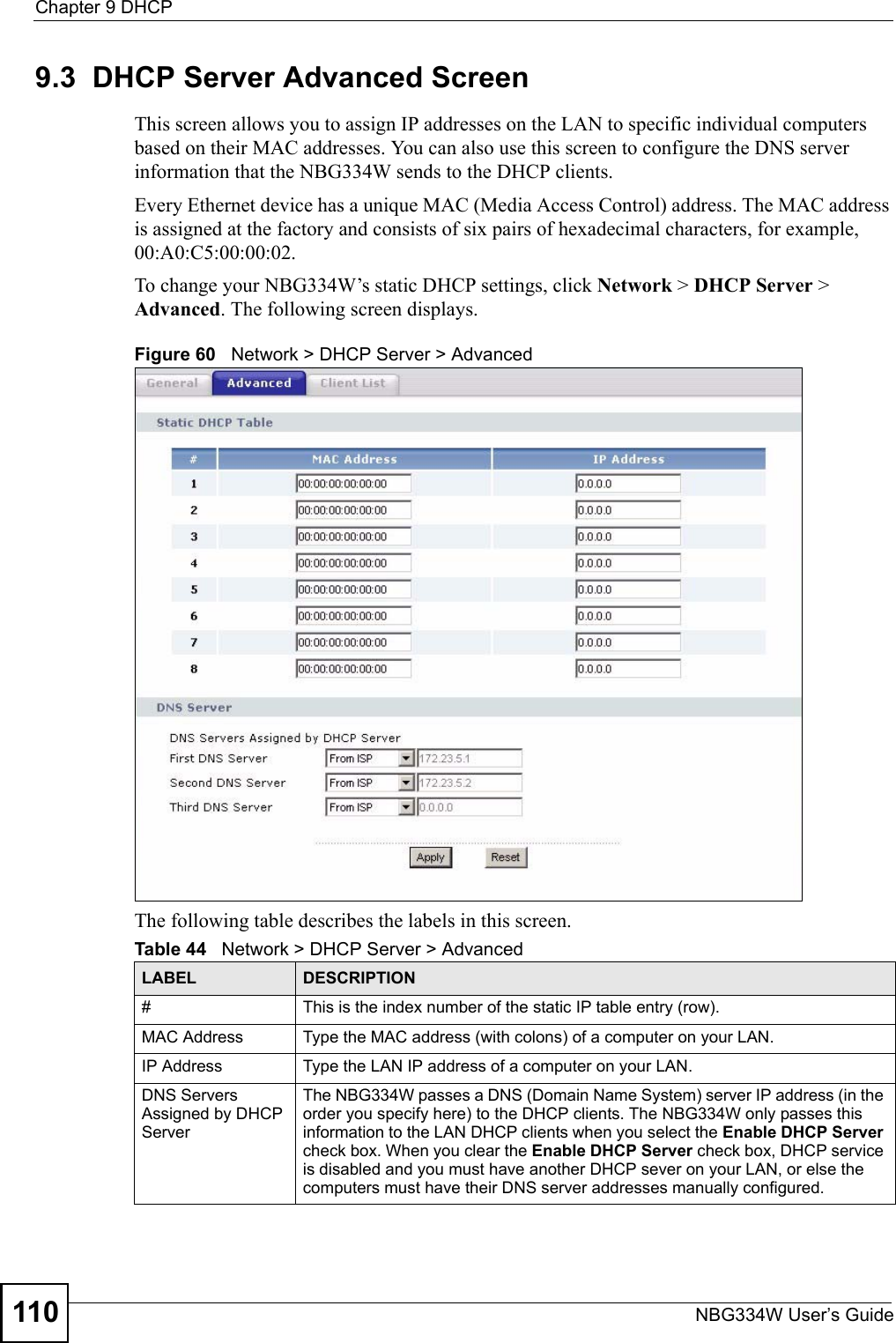
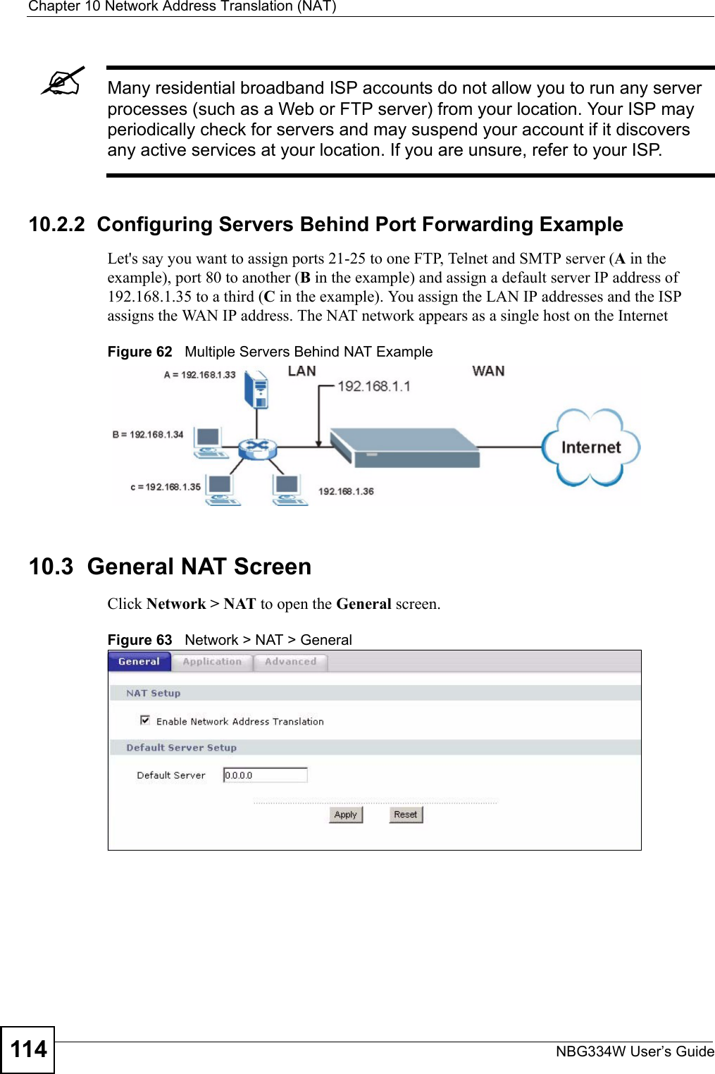
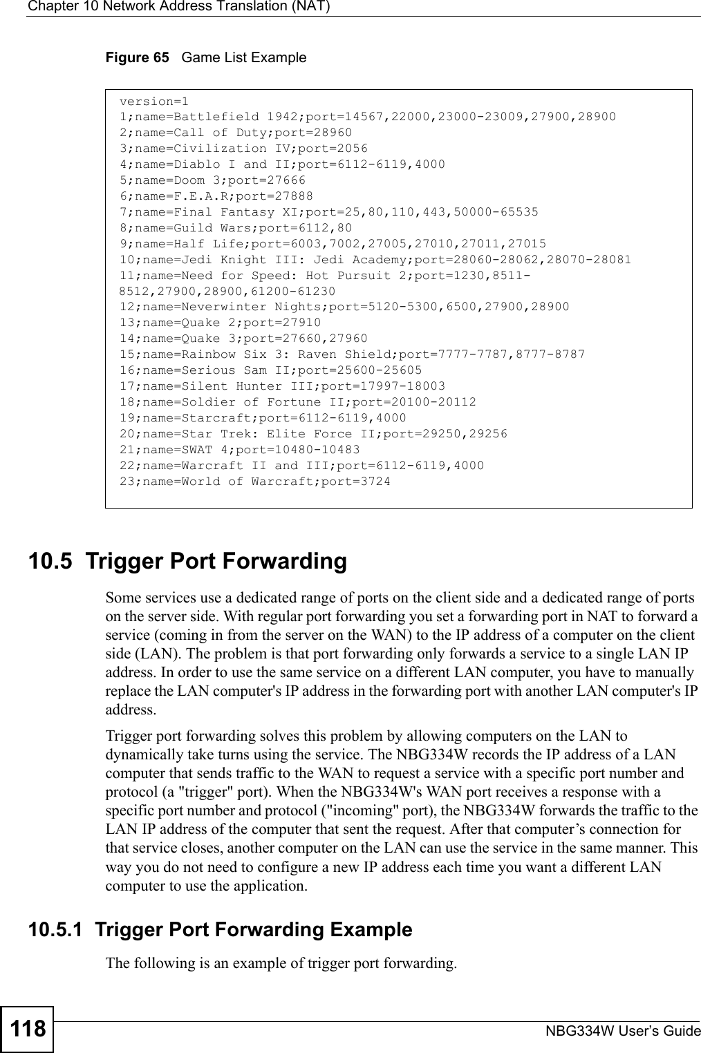

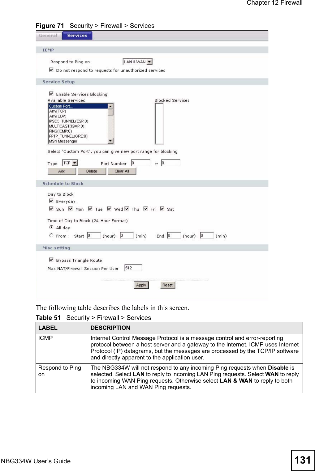
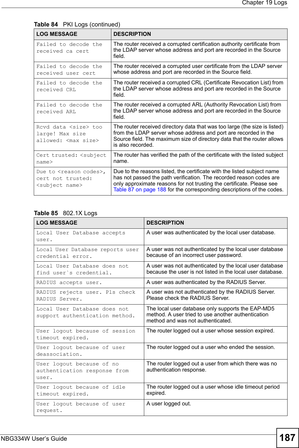
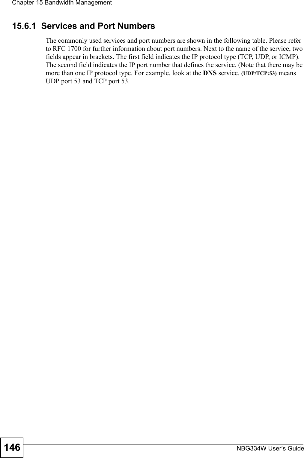
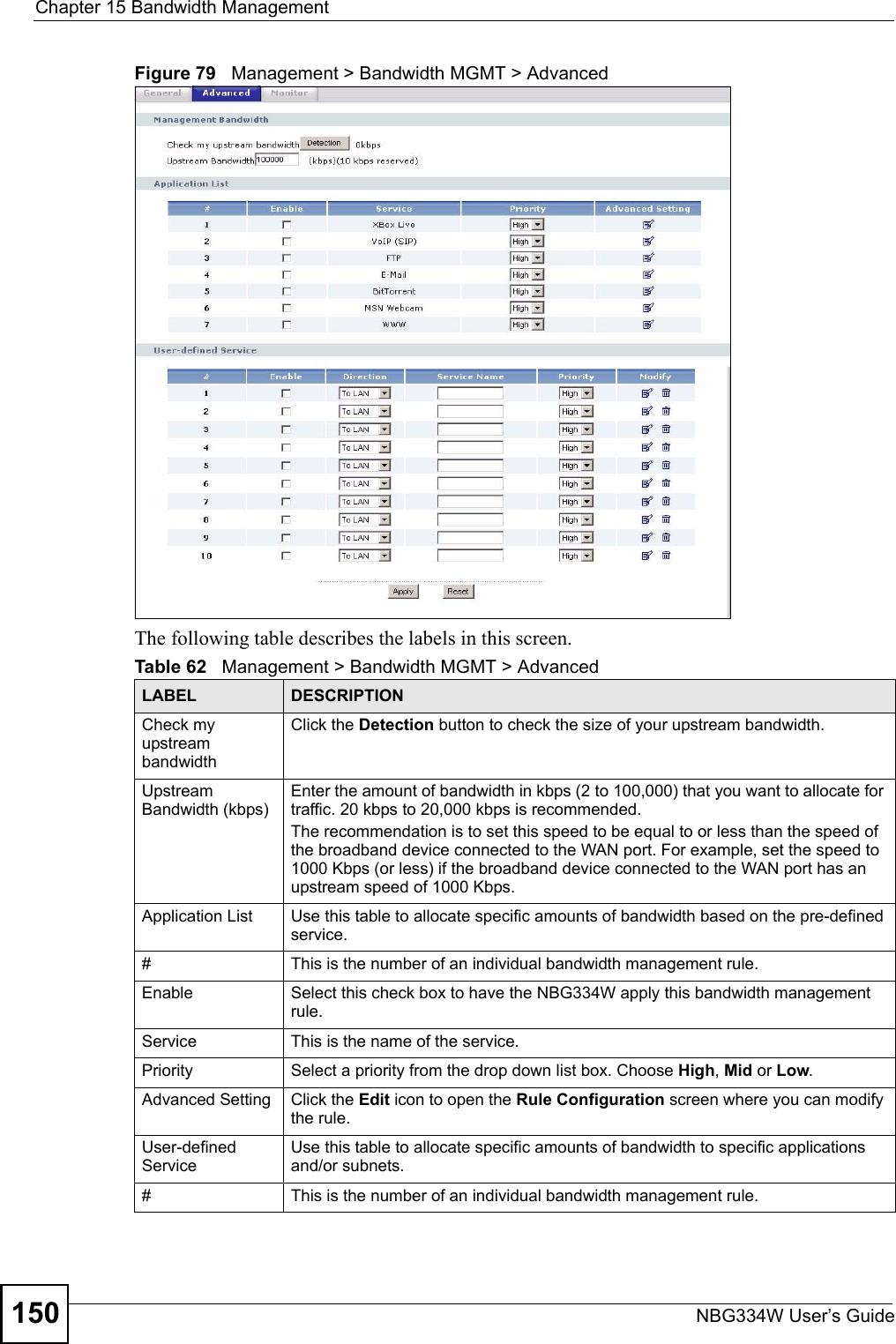
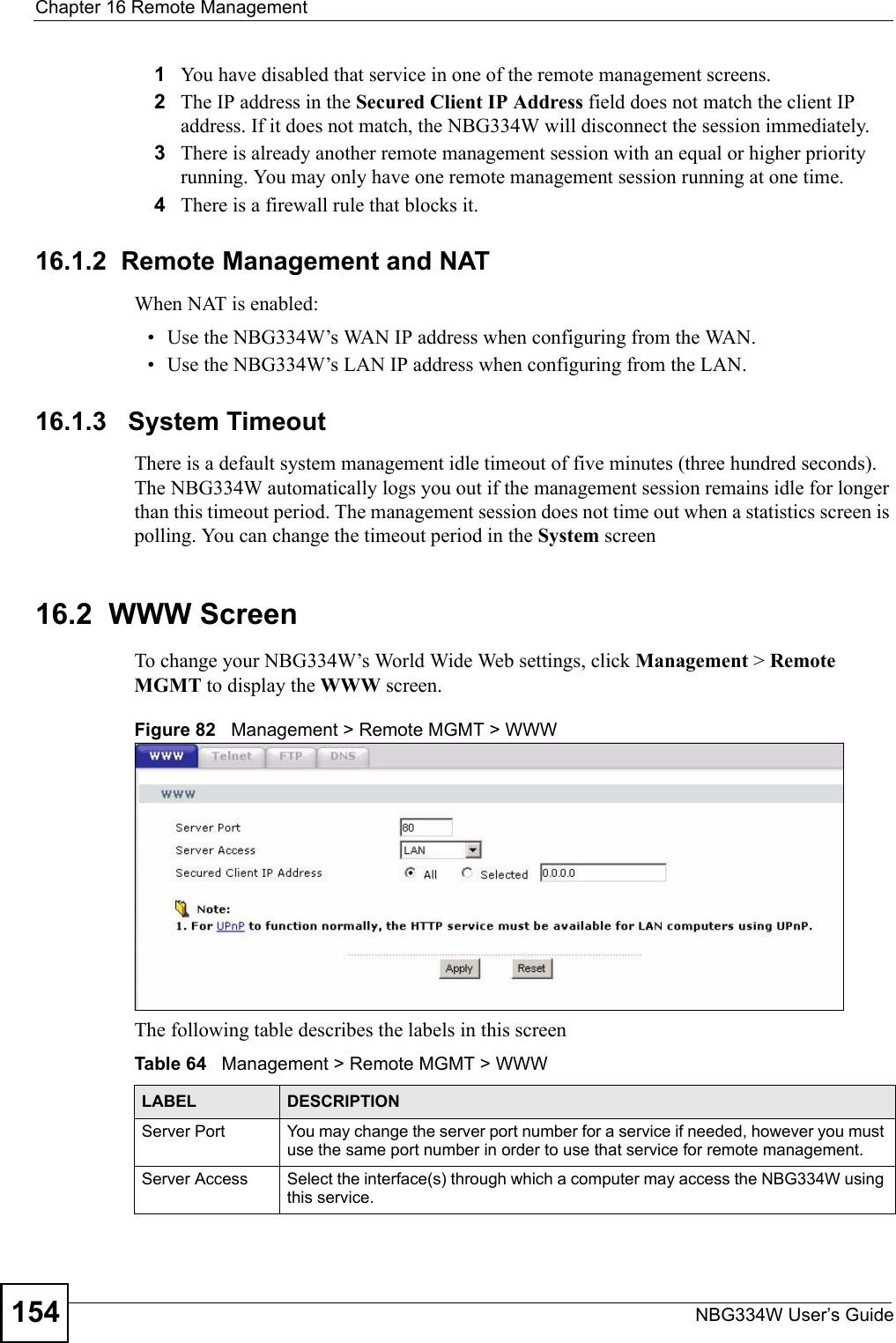
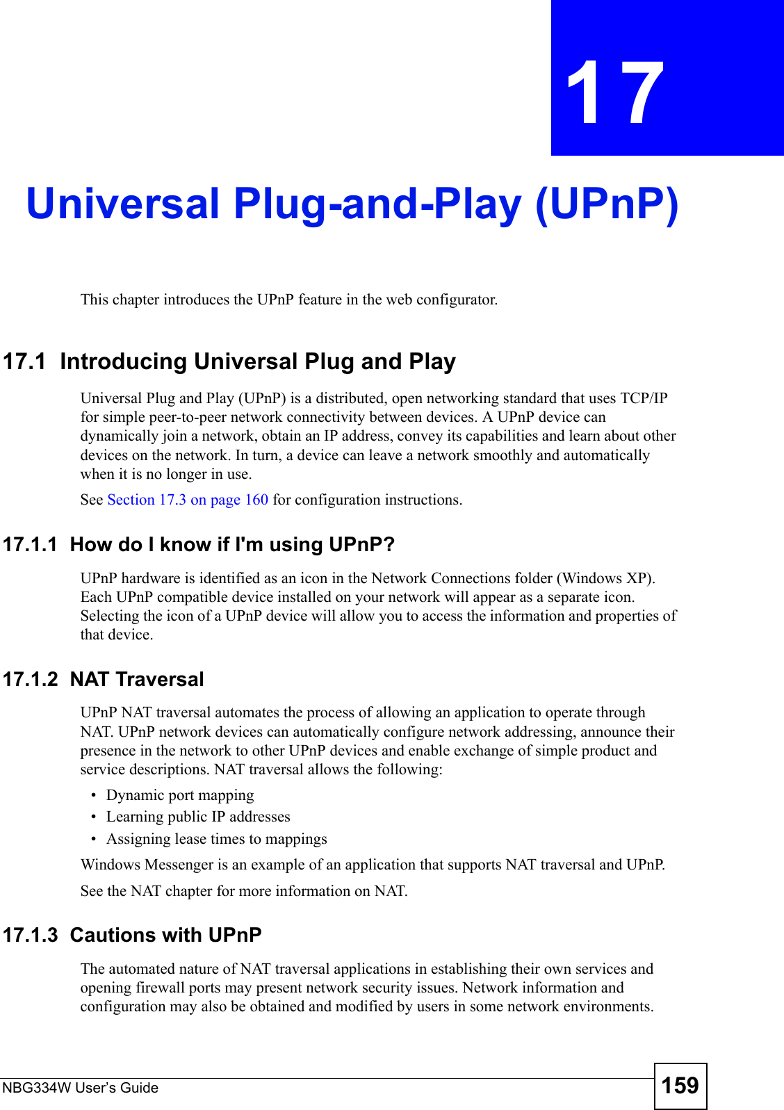
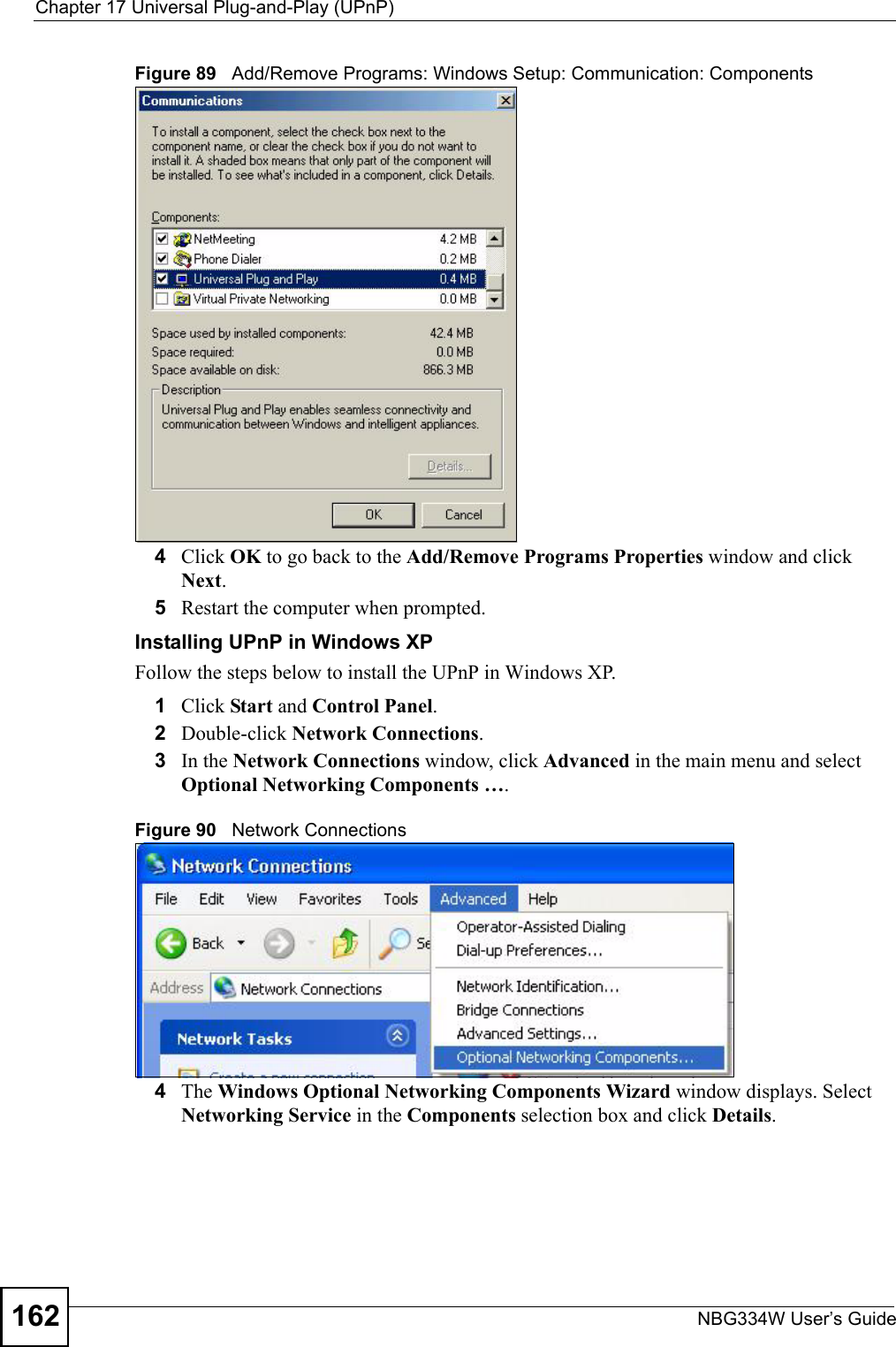
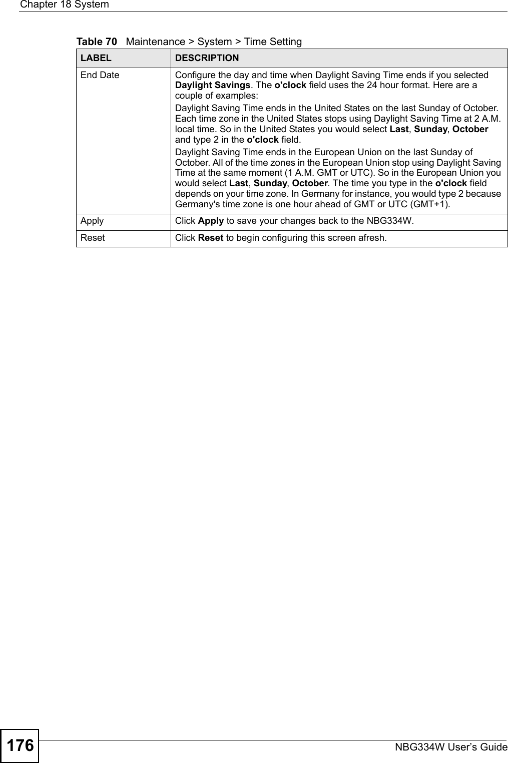
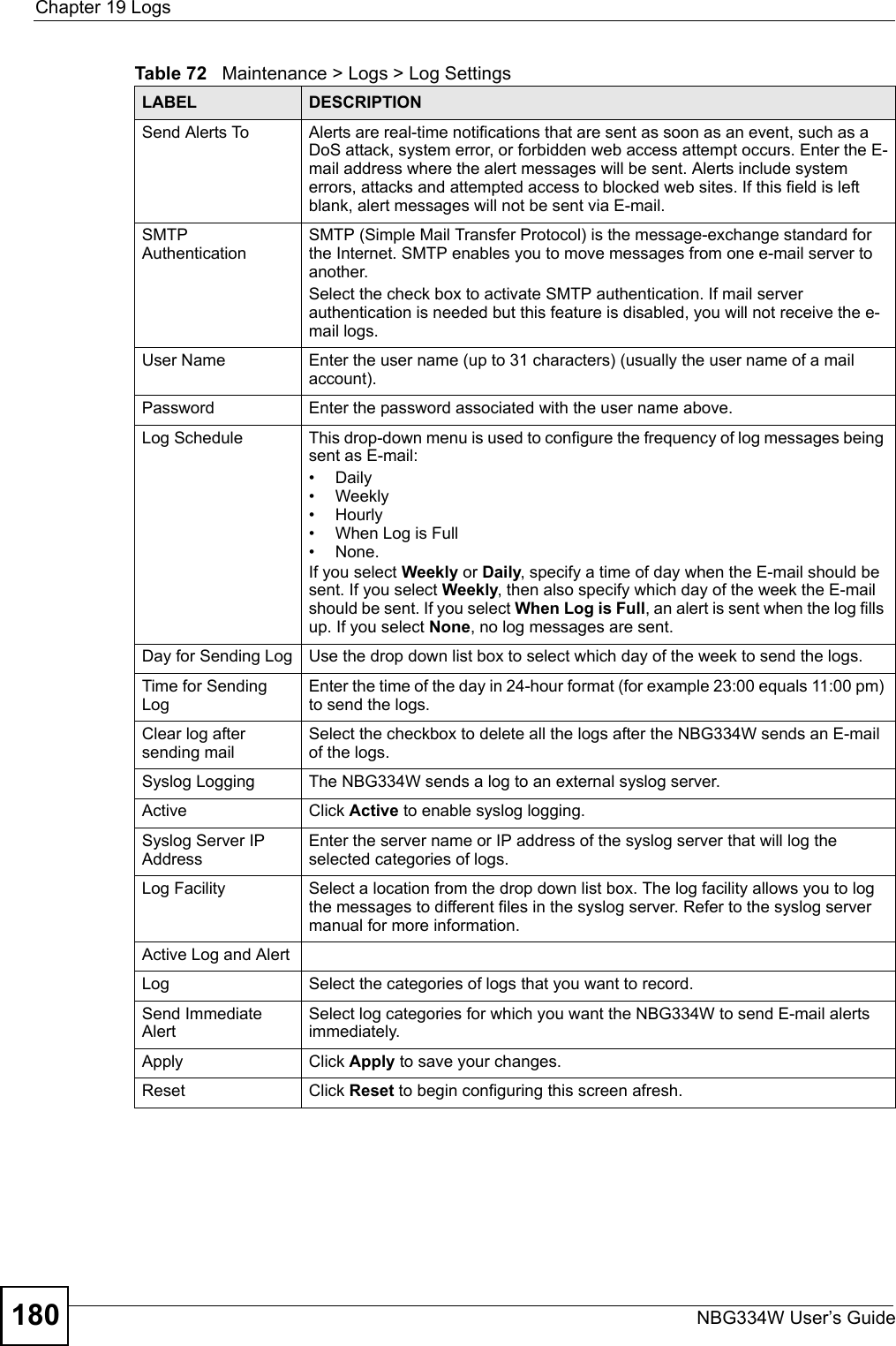
![Chapter 12 FirewallNBG334W User’s Guide132Do not respond to requests for unauthorized servicesSelect this option to prevent hackers from finding the NBG334W by probing for unused ports. If you select this option, the NBG334W will not respond to port request(s) for unused ports, thus leaving the unused ports and the NBG334W unseen. By default this option is not selected and the NBG334W will reply with an ICMP Port Unreachable packet for a port probe on its unused UDP ports, and a TCP Reset packet for a port probe on its unused TCP ports. Note that the probing packets must first traverse the NBG334W's firewall mechanism before reaching this anti-probing mechanism. Therefore if the firewall mechanism blocks a probing packet, the NBG334W reacts based on the firewall policy, which by default, is to send a TCP reset packet for a blocked TCP packet. You can use the command "sys firewall tcprst rst [on|off]" to change this policy. When the firewall mechanism blocks a UDP packet, it drops the packet without sending a response packet.Service SetupEnable Services BlockingSelect this check box to enable this feature.Available ServicesThis is a list of pre-defined services (ports) you may prohibit your LAN computers from using. Select the port you want to block using the drop-down list and click Add to add the port to the Blocked Services field.Blocked Services This is a list of services (ports) that will be inaccessible to computers on your LAN once you enable service blocking. Custom Port A custom port is a service that is not available in the pre-defined Available Services list and you must define using the next two fields.Type Choose the IP port (TCP or UDP) that defines your customized port from the drop down list box.Port Number Enter the port number range that defines the service. For example, if you want to define the Gnutella service, then select TCP type and enter a port range from 6345 to 6349.Add Select a service from the Available Services drop-down list and then click Add to add a service to the Blocked ServicesDelete Select a service from the Blocked Services list and then click Delete to remove this service from the list.Clear All Click Clear All to empty the Blocked Services.Schedule to BlockDay to Block: Select a check box to configure which days of the week (or everyday) you want service blocking to be active. Time of Day to Block (24-Hour Format)Select the time of day you want service blocking to take effect. Configure blocking to take effect all day by selecting All Day. You can also configure specific times by selecting From and entering the start time in the Start (hour) and Start (min) fields and the end time in the End (hour) and End (min) fields. Enter times in 24-hour format, for example, "3:00pm" should be entered as "15:00".Misc settingBypass Triangle RouteSelect this check box to have the NBG334W firewall ignore the use of triangle route topology on the network. Max NAT/Firewall Session Per UserType a number ranging from 1 to 2048 to limit the number of NAT/firewall sessions that a host can create.Apply Click Apply to save the settings. Reset Click Reset to start configuring this screen again. Table 51 Security > Firewall > ServicesLABEL DESCRIPTION](https://usermanual.wiki/ZyXEL-Communications/NBG334W.Users-Manual-Part-3/User-Guide-823267-Page-33.png)
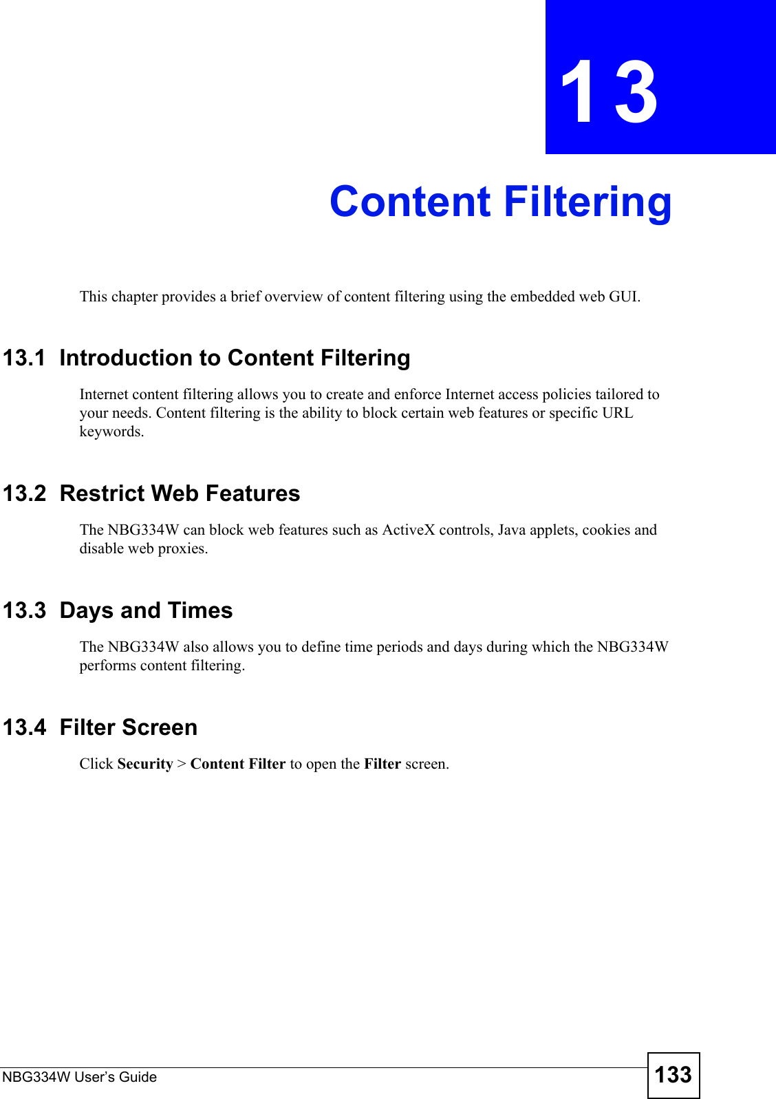
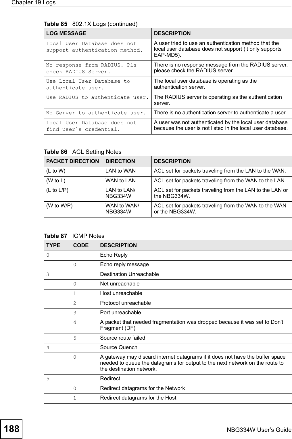
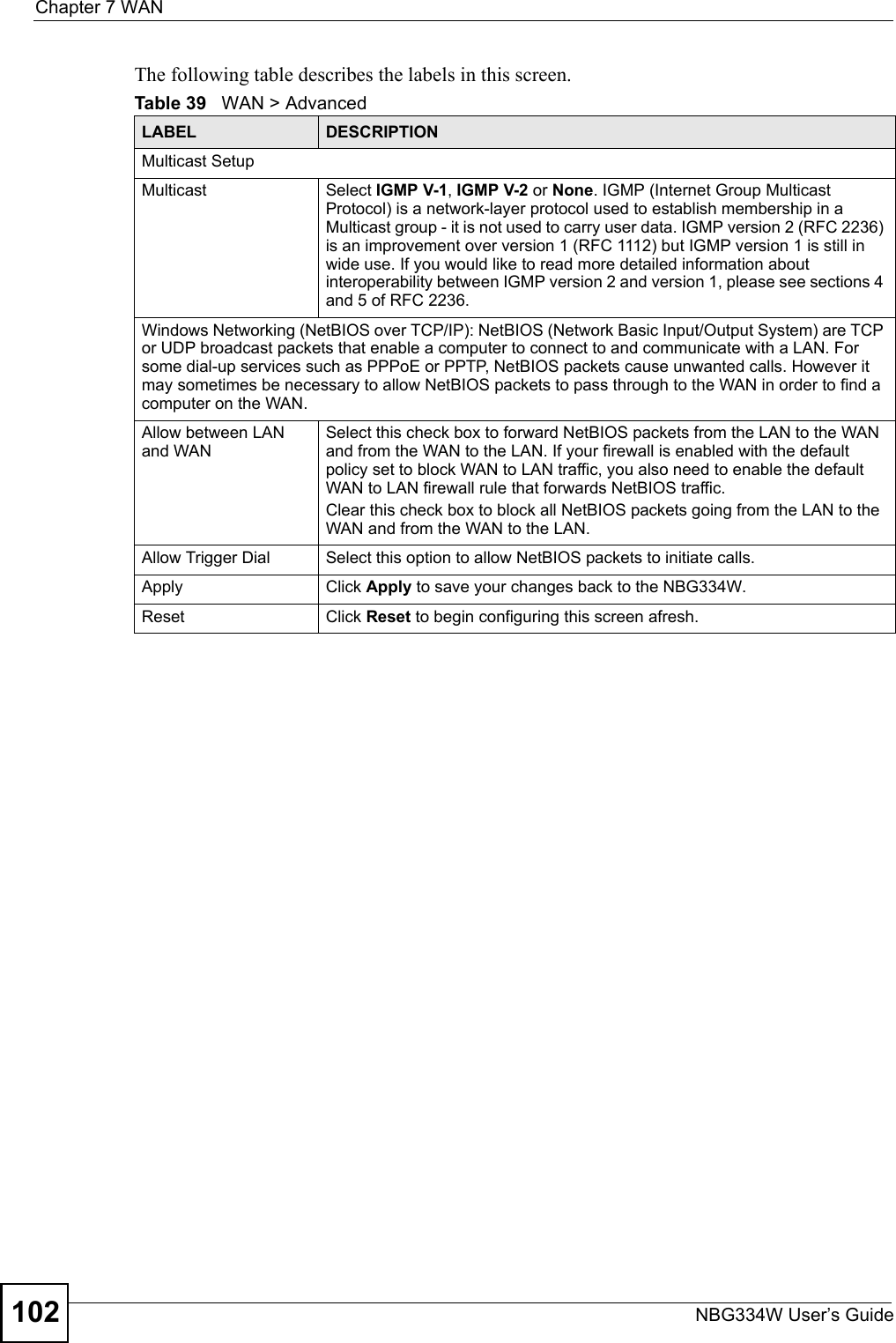
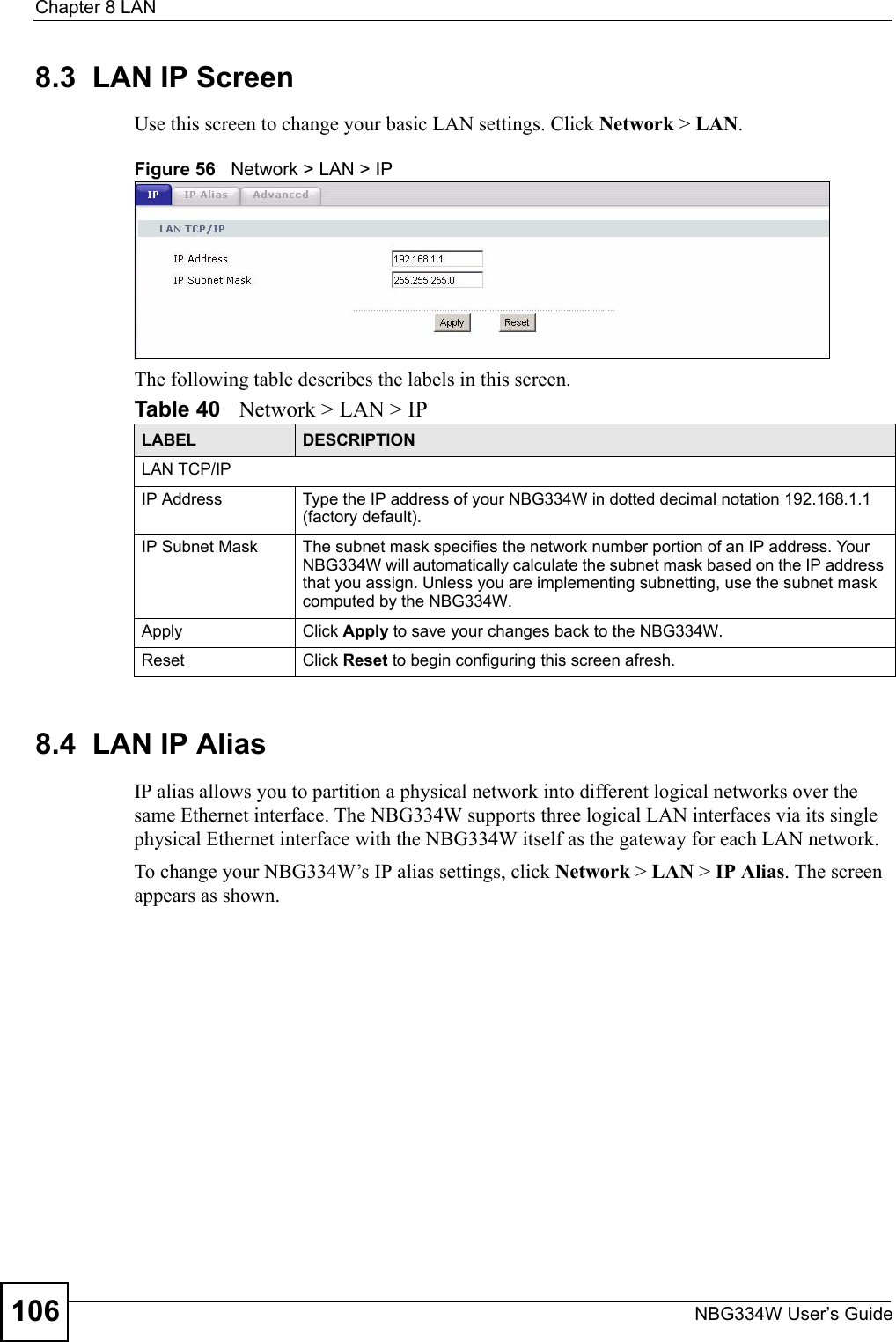
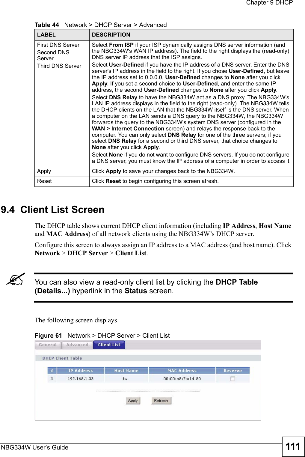
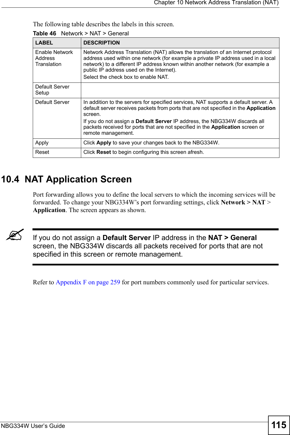
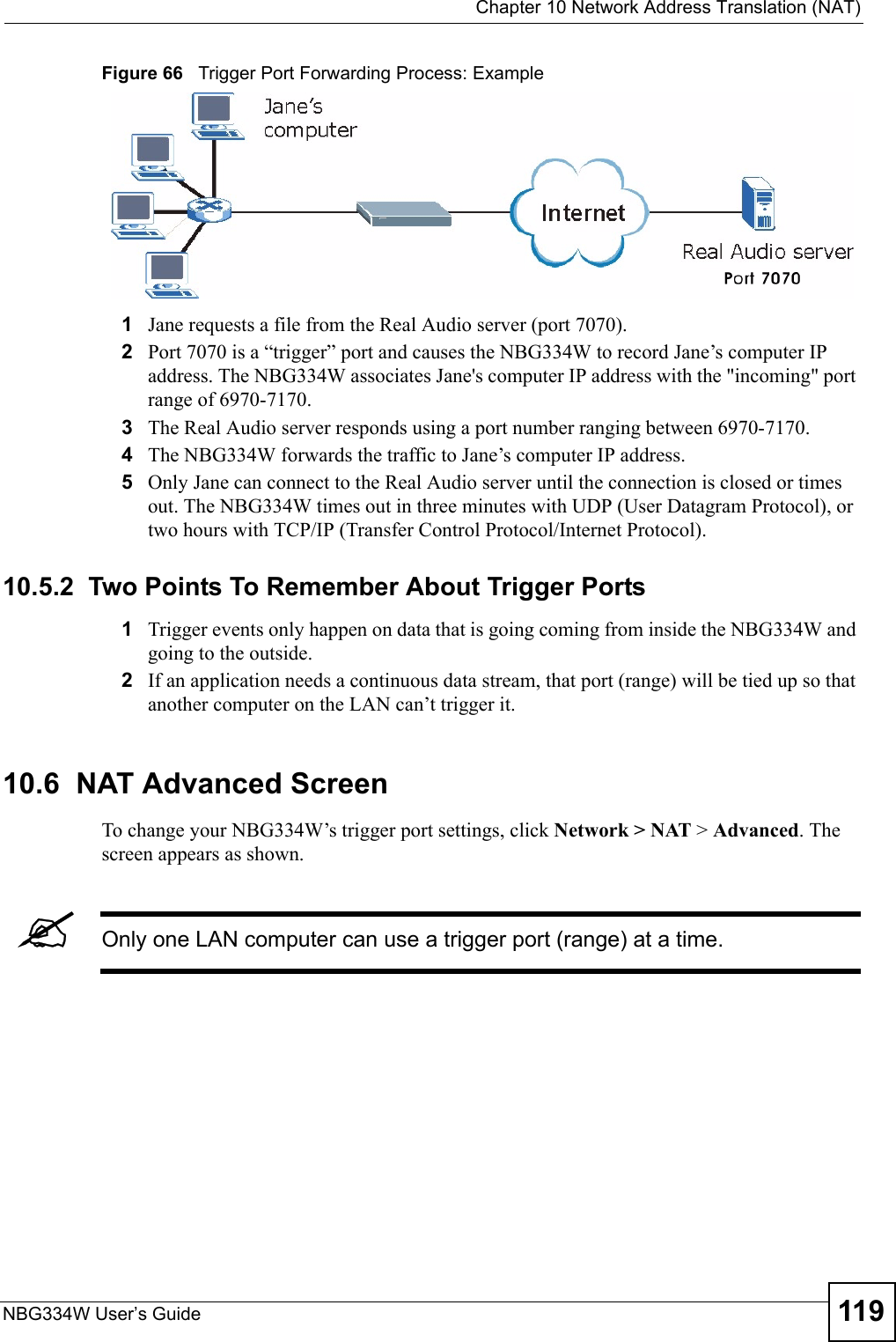
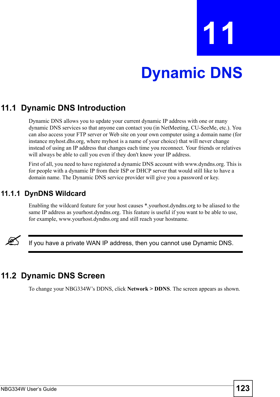
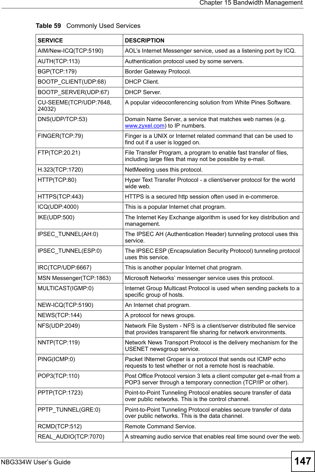
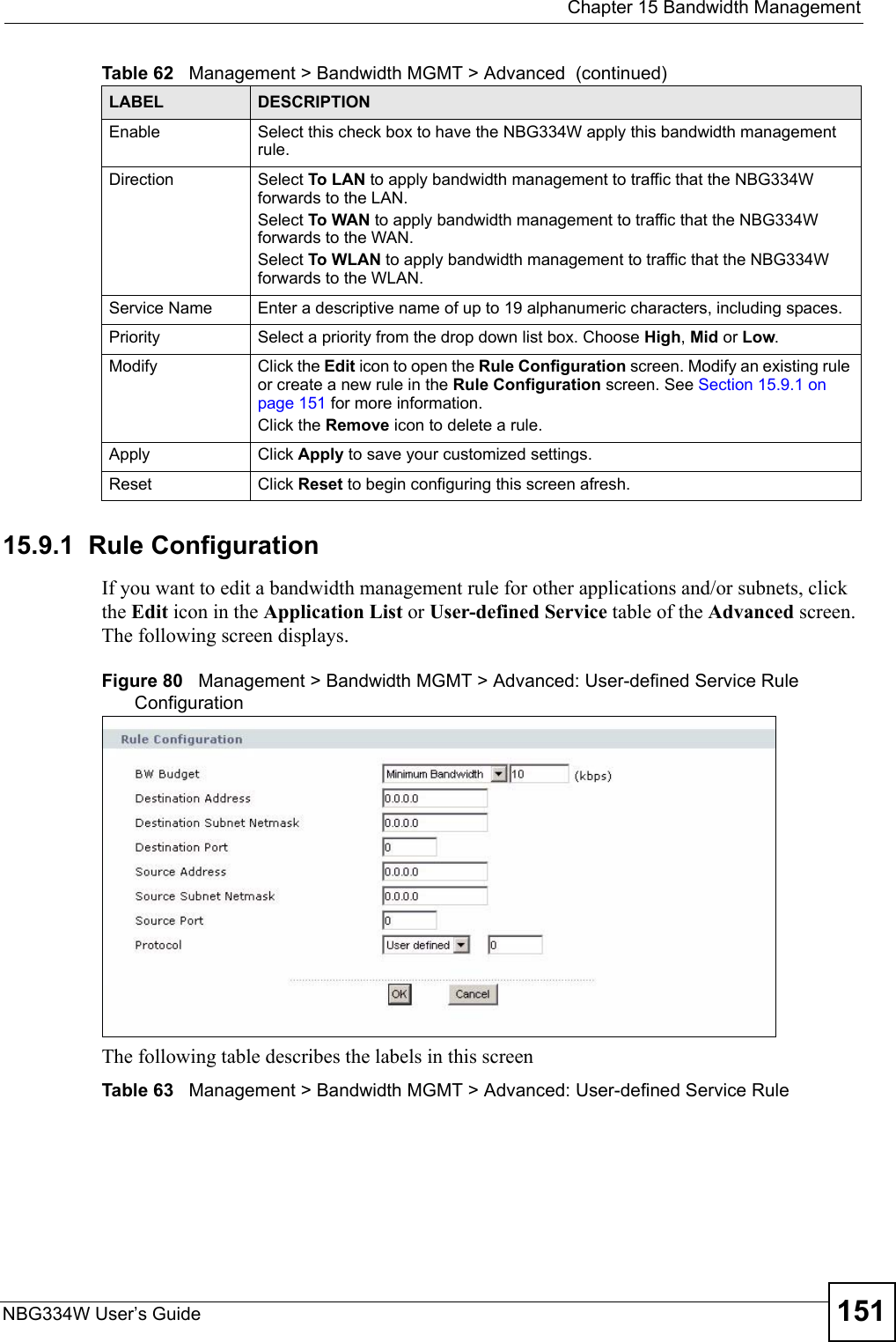
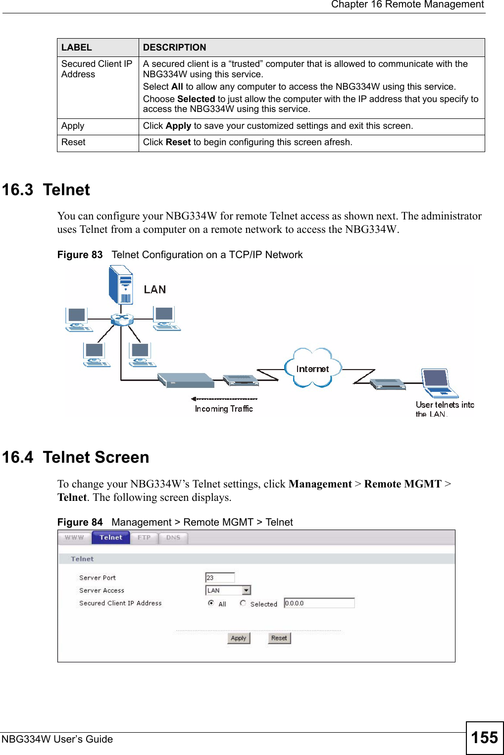
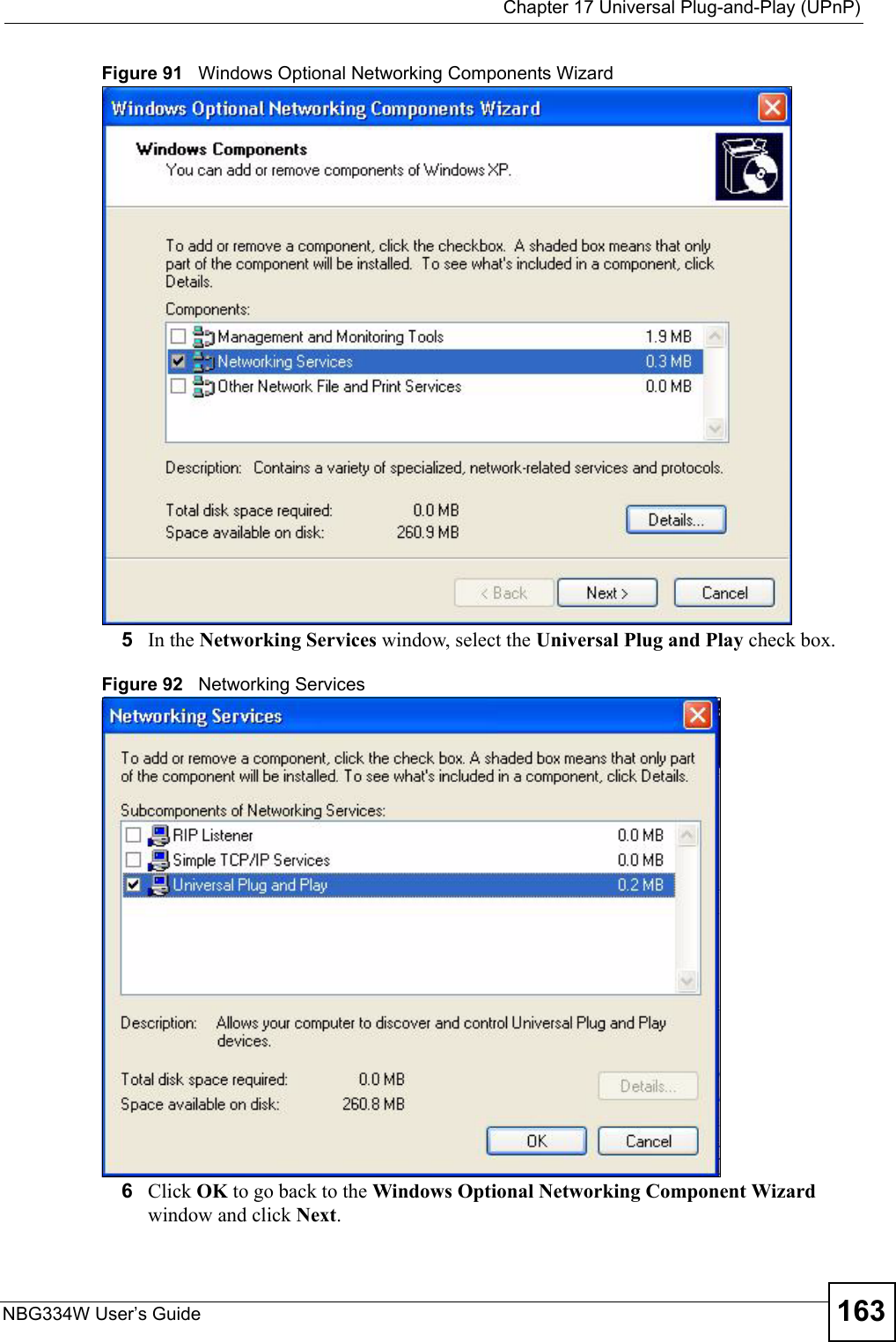
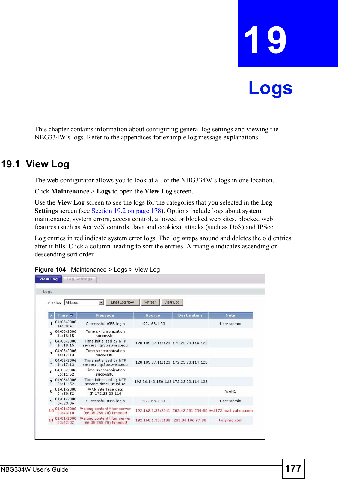
![Chapter 13 Content FilteringNBG334W User’s Guide13613.6 Customizing Keyword Blocking URL CheckingYou can use commands to set how much of a website’s URL the content filter is to check for keyword blocking. See the appendices for information on how to access and use the command interpreter.13.6.1 Domain Name or IP Address URL CheckingBy default, the NBG334W checks the URL’s domain name or IP address when performing keyword blocking.This means that the NBG334W checks the characters that come before the first slash in the URL.For example, with the URL www.zyxel.com.tw/news/pressroom.php, content filtering only searches for keywords within www.zyxel.com.tw.13.6.2 Full Path URL CheckingFull path URL checking has the NBG334W check the characters that come before the last slash in the URL.For example, with the URL www.zyxel.com.tw/news/pressroom.php, full path URL checking searches for keywords within www.zyxel.com.tw/news/.Use the ip urlfilter customize actionFlags 6 [disable | enable] command to extend (or not extend) the keyword blocking search to include the URL's full path.13.6.3 File Name URL CheckingFilename URL checking has the NBG334W check all of the characters in the URL.For example, filename URL checking searches for keywords within the URL www.zyxel.com.tw/news/pressroom.php.Use the ip urlfilter customize actionFlags 8 [disable | enable] command to extend (or not extend) the keyword blocking search to include the URL's complete filename.Apply Click Apply to save your customized settings and exit this screen.Reset Click Reset to begin configuring this screen afreshTable 53 Security > Content Filter > ScheduleLABEL DESCRIPTION](https://usermanual.wiki/ZyXEL-Communications/NBG334W.Users-Manual-Part-3/User-Guide-823267-Page-37.png)

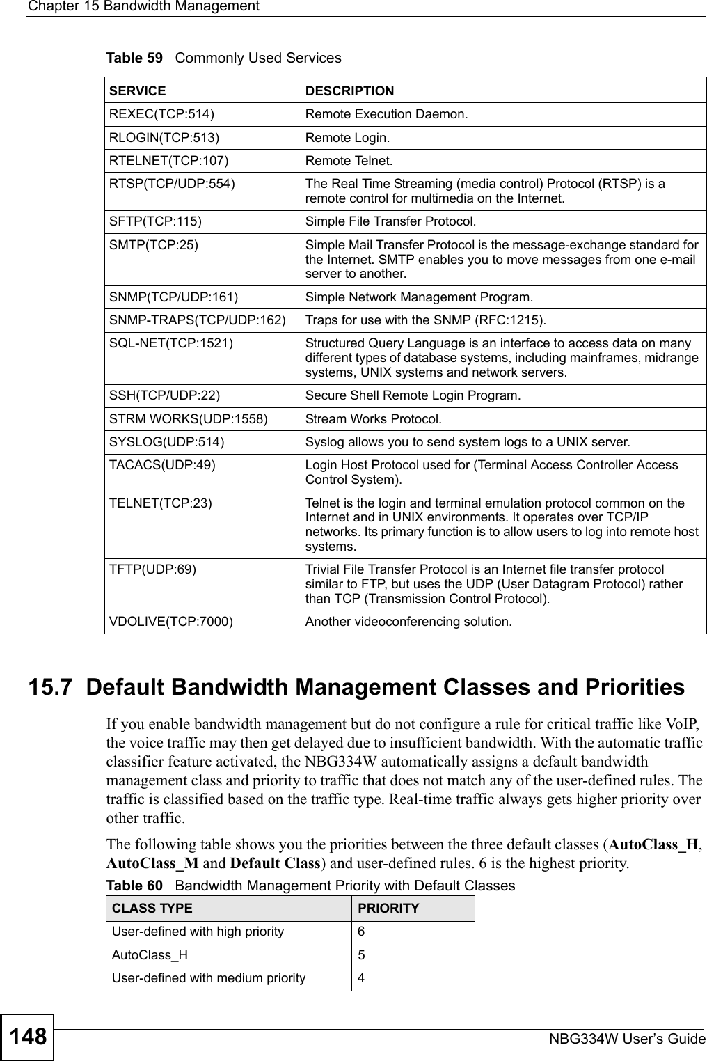
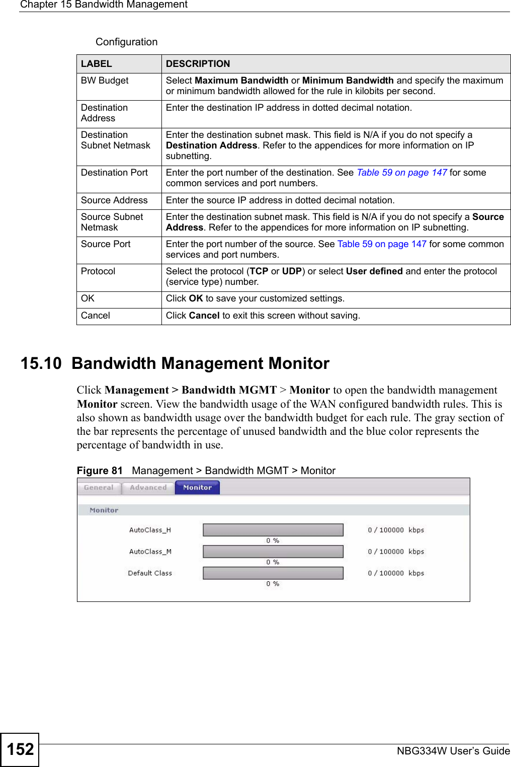
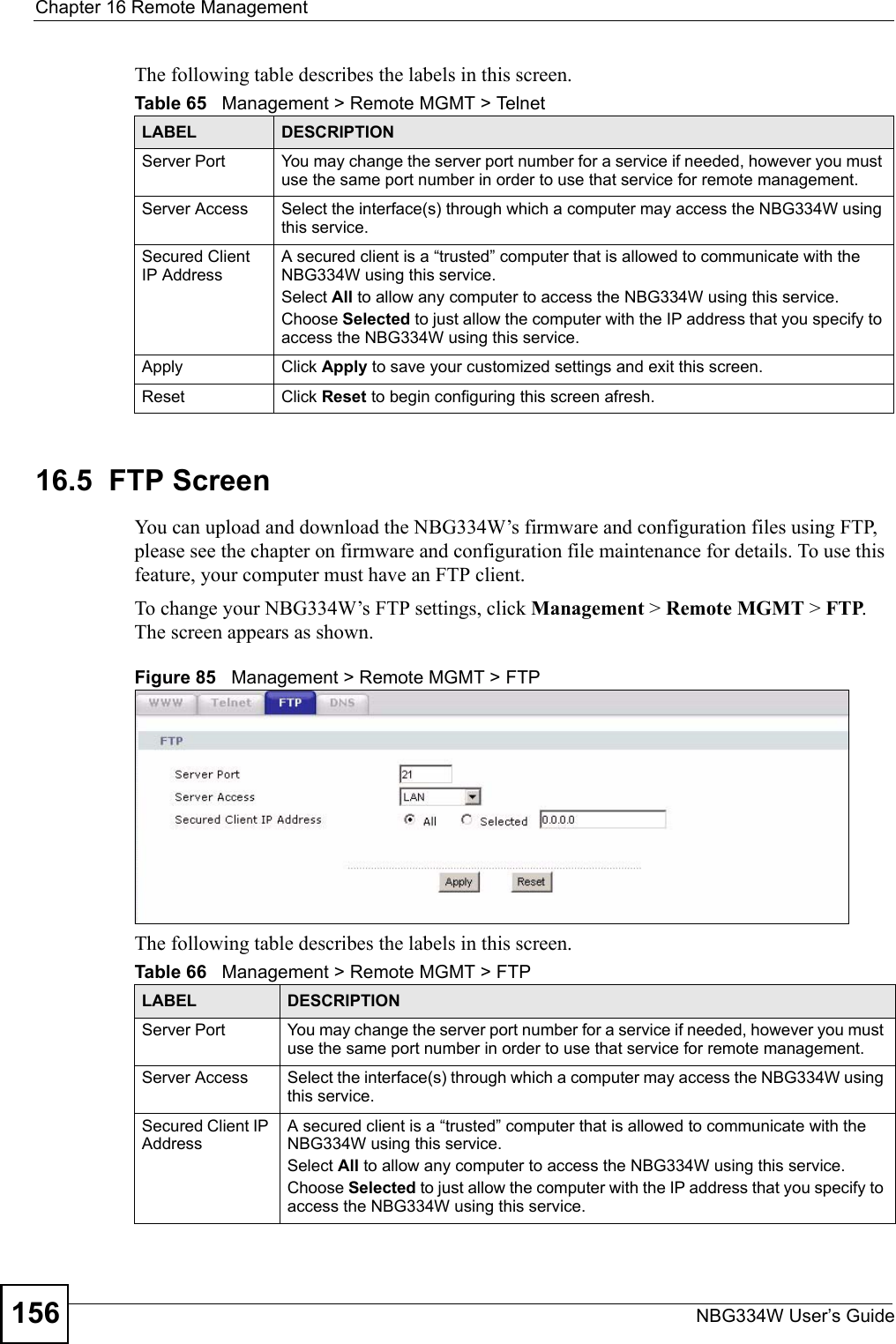
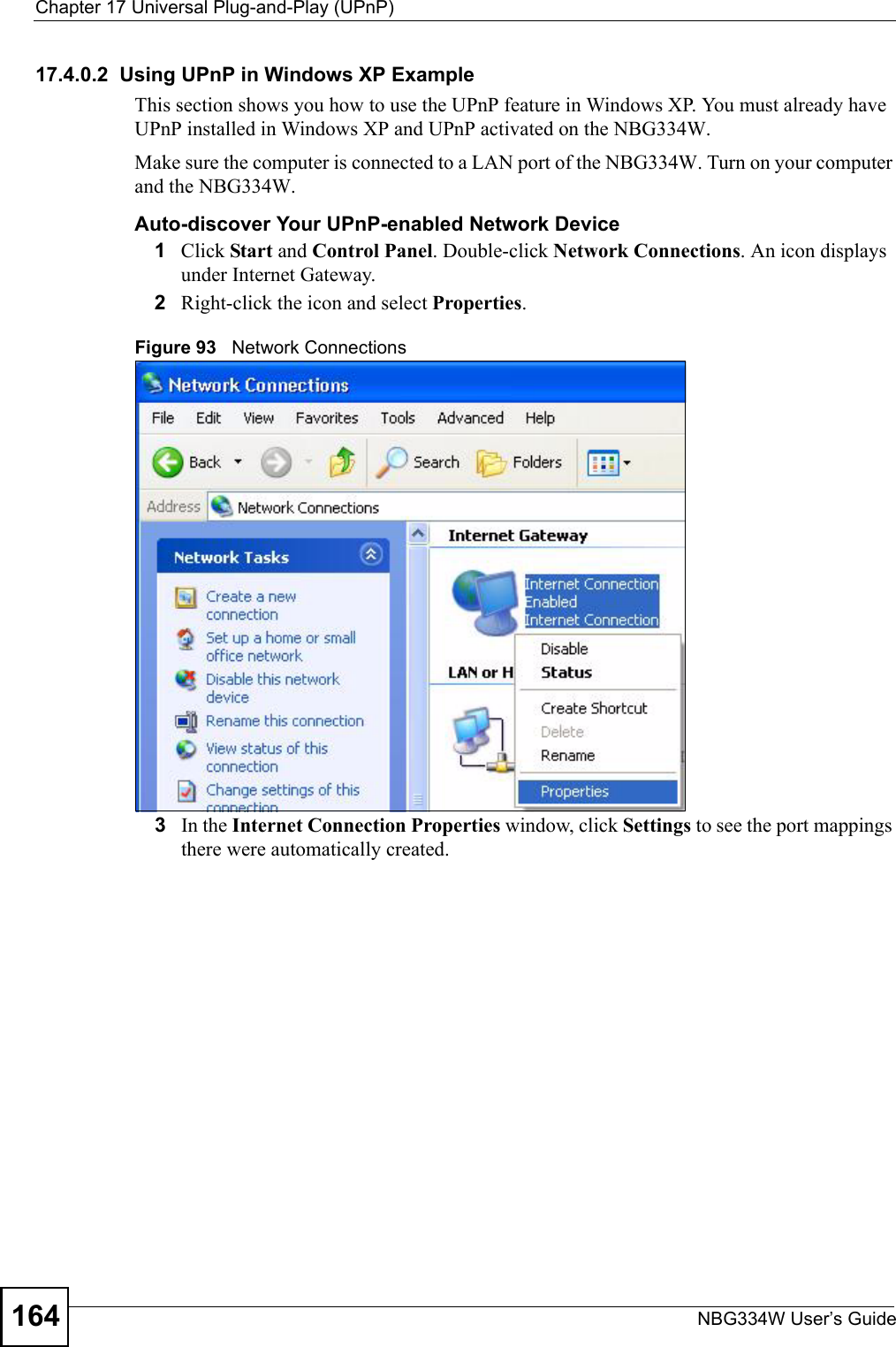


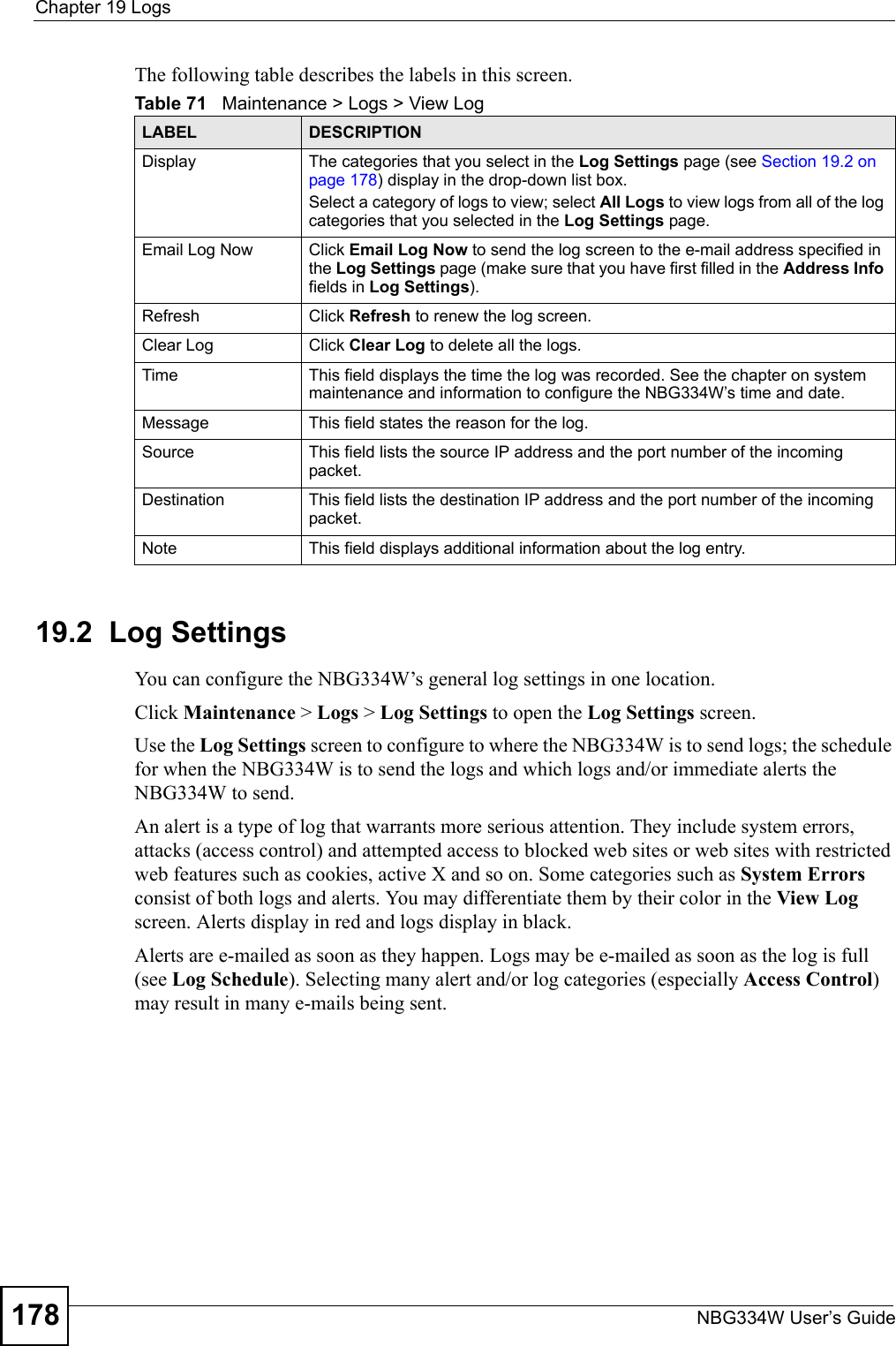
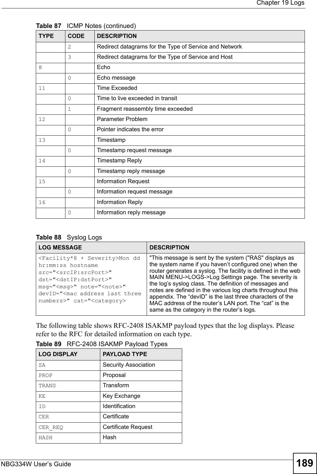
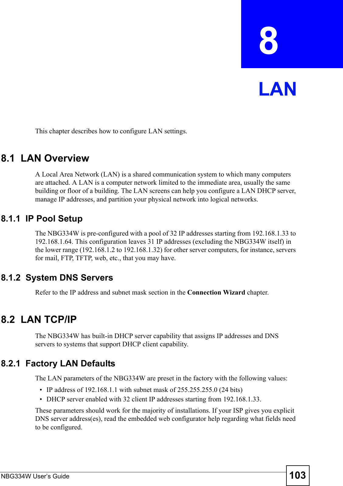
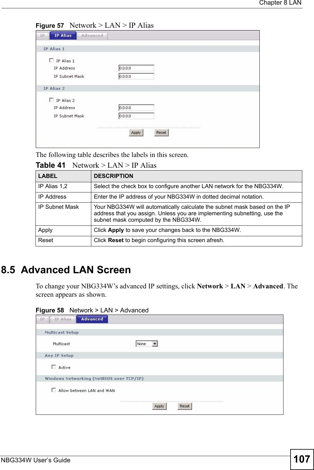
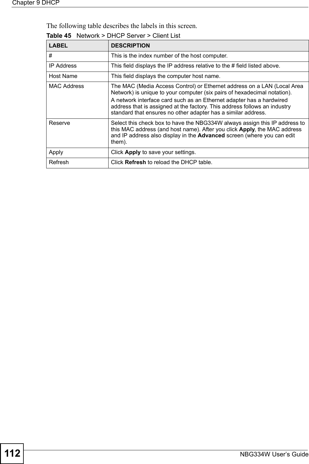
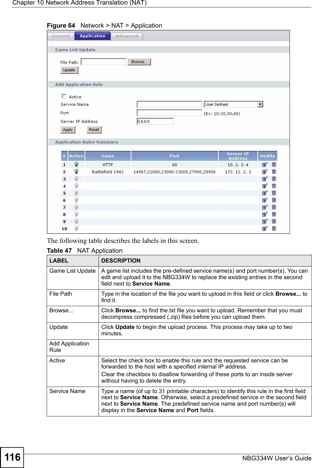
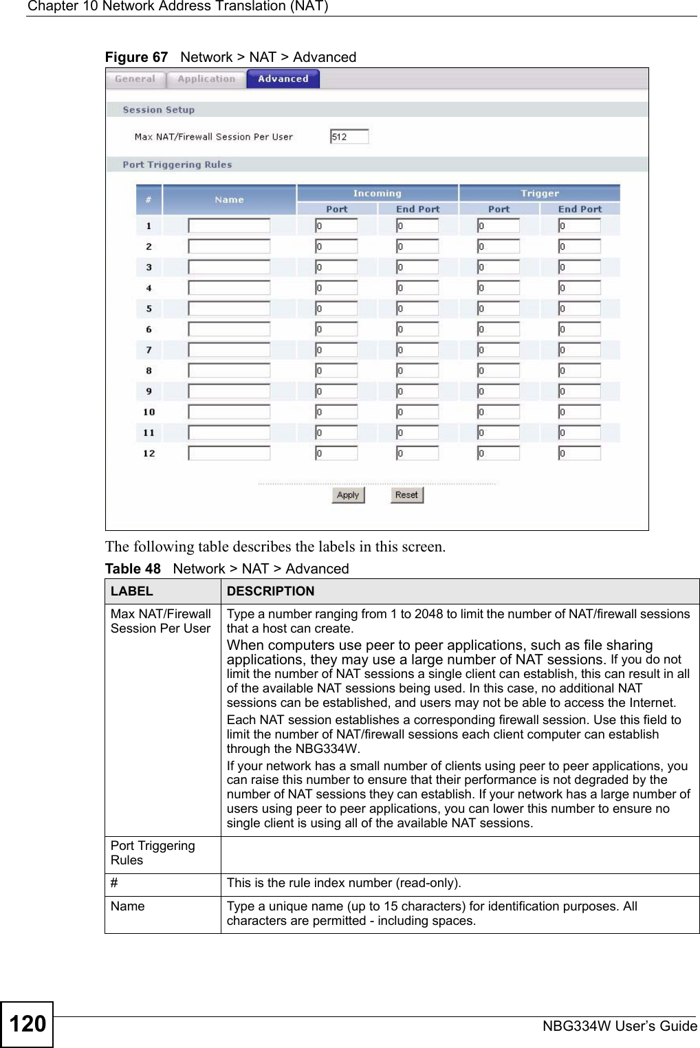
![Chapter 19 LogsNBG334W User’s Guide182 Table 74 System Error LogsLOG MESSAGE DESCRIPTION%s exceeds the max. number of session per host!This attempt to create a NAT session exceeds the maximum number of NAT session table entries allowed to be created per host.setNetBIOSFilter: calloc errorThe router failed to allocate memory for the NetBIOS filter settings.readNetBIOSFilter: calloc errorThe router failed to allocate memory for the NetBIOS filter settings.WAN connection is down. A WAN connection is down. You cannot access the network through this interface.Table 75 Access Control LogsLOG MESSAGE DESCRIPTIONFirewall default policy: [TCP | UDP | IGMP | ESP | GRE | OSPF] <Packet Direction>Attempted TCP/UDP/IGMP/ESP/GRE/OSPF access matched the default policy and was blocked or forwarded according to the default policy’s setting.Firewall rule [NOT] match:[TCP | UDP | IGMP | ESP | GRE | OSPF] <Packet Direction>, <rule:%d>Attempted TCP/UDP/IGMP/ESP/GRE/OSPF access matched (or did not match) a configured firewall rule (denoted by its number) and was blocked or forwarded according to the rule. Triangle route packet forwarded: [TCP | UDP | IGMP | ESP | GRE | OSPF]The firewall allowed a triangle route session to pass through.Packet without a NAT table entry blocked: [TCP | UDP | IGMP | ESP | GRE | OSPF]The router blocked a packet that didn't have a corresponding NAT table entry.Router sent blocked web site message: TCPThe router sent a message to notify a user that the router blocked access to a web site that the user requested.Table 76 TCP Reset LogsLOG MESSAGE DESCRIPTIONUnder SYN flood attack, sent TCP RSTThe router sent a TCP reset packet when a host was under a SYN flood attack (the TCP incomplete count is per destination host.) Exceed TCP MAX incomplete, sent TCP RSTThe router sent a TCP reset packet when the number of TCP incomplete connections exceeded the user configured threshold. (the TCP incomplete count is per destination host.) Note: Refer to TCP Maximum Incomplete in the Firewall Attack Alerts screen. Peer TCP state out of order, sent TCP RSTThe router sent a TCP reset packet when a TCP connection state was out of order.Note: The firewall refers to RFC793 Figure 6 to check the TCP state.](https://usermanual.wiki/ZyXEL-Communications/NBG334W.Users-Manual-Part-3/User-Guide-823267-Page-83.png)
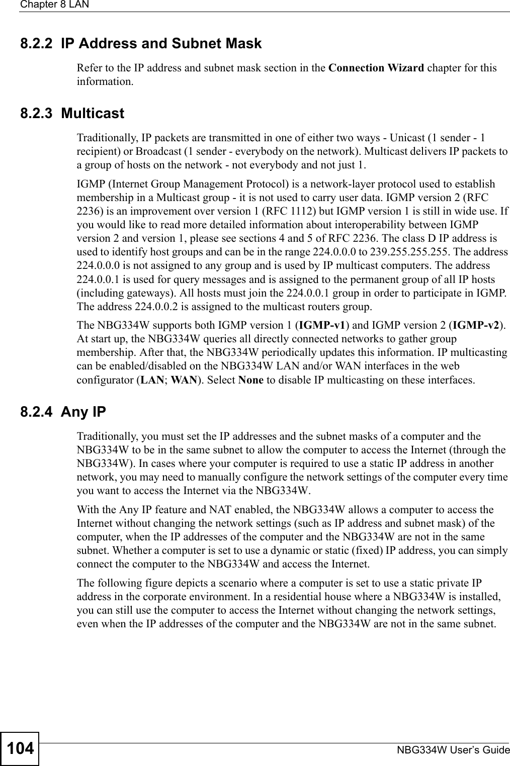
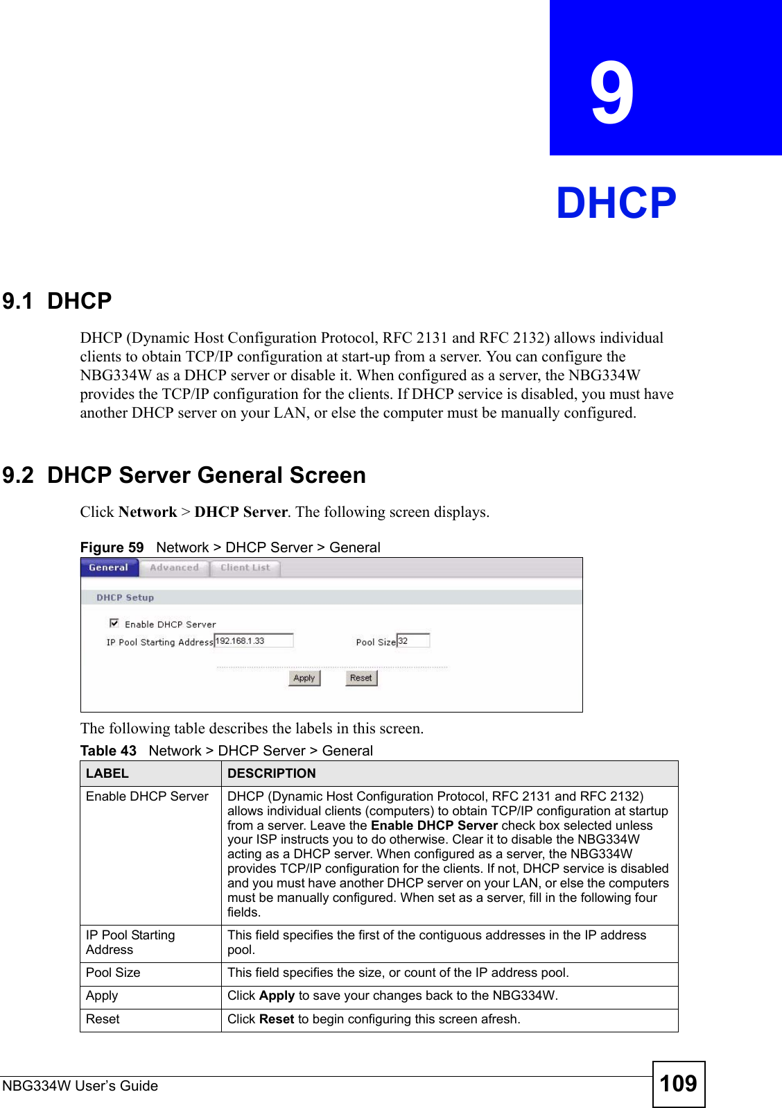
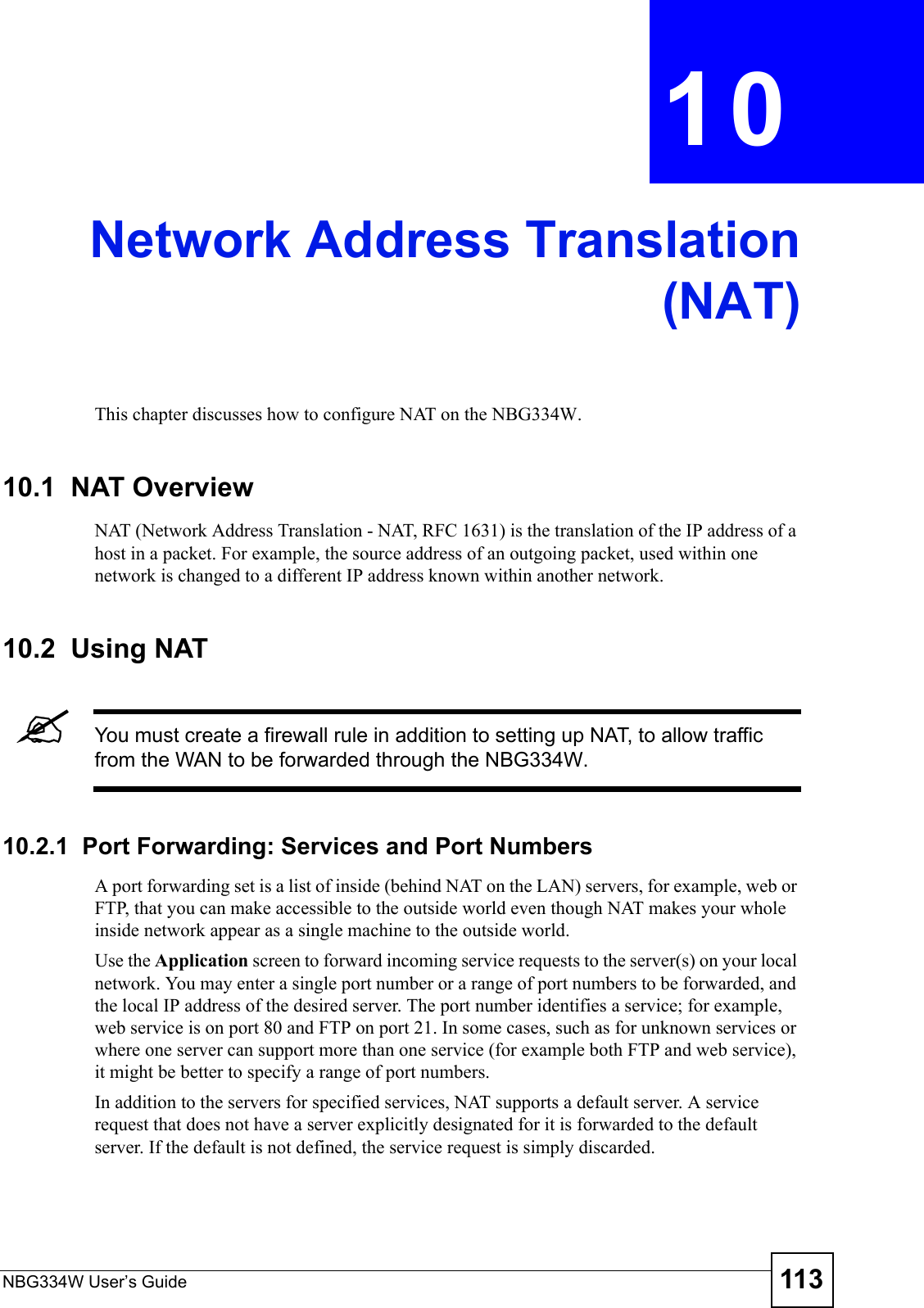
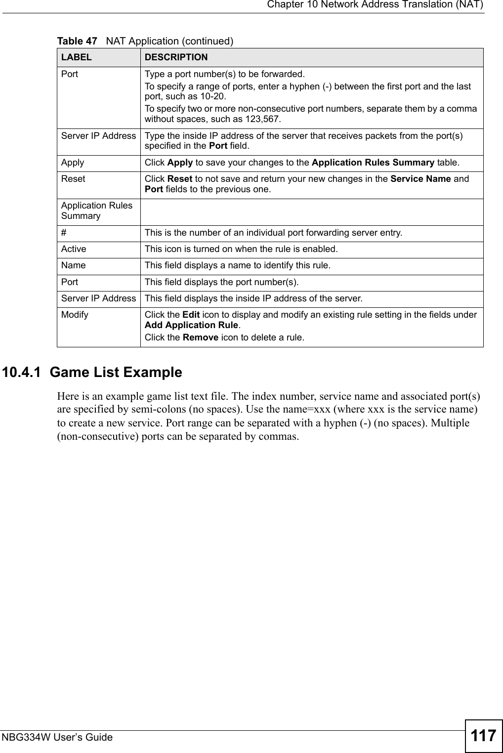
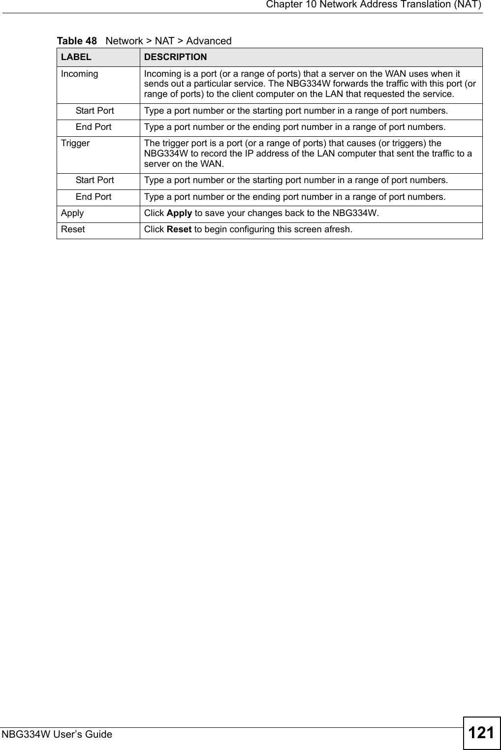
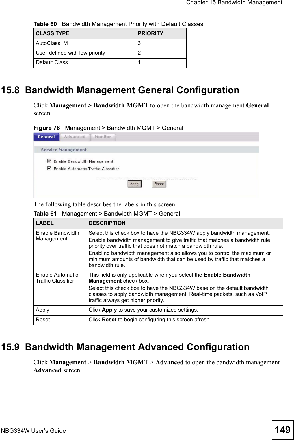
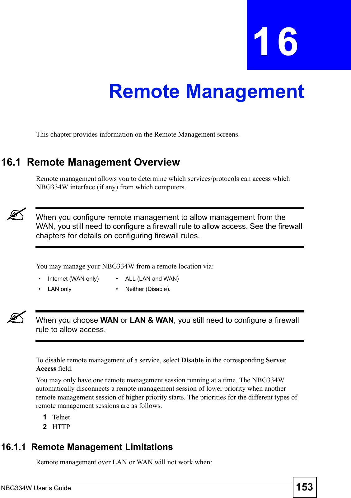
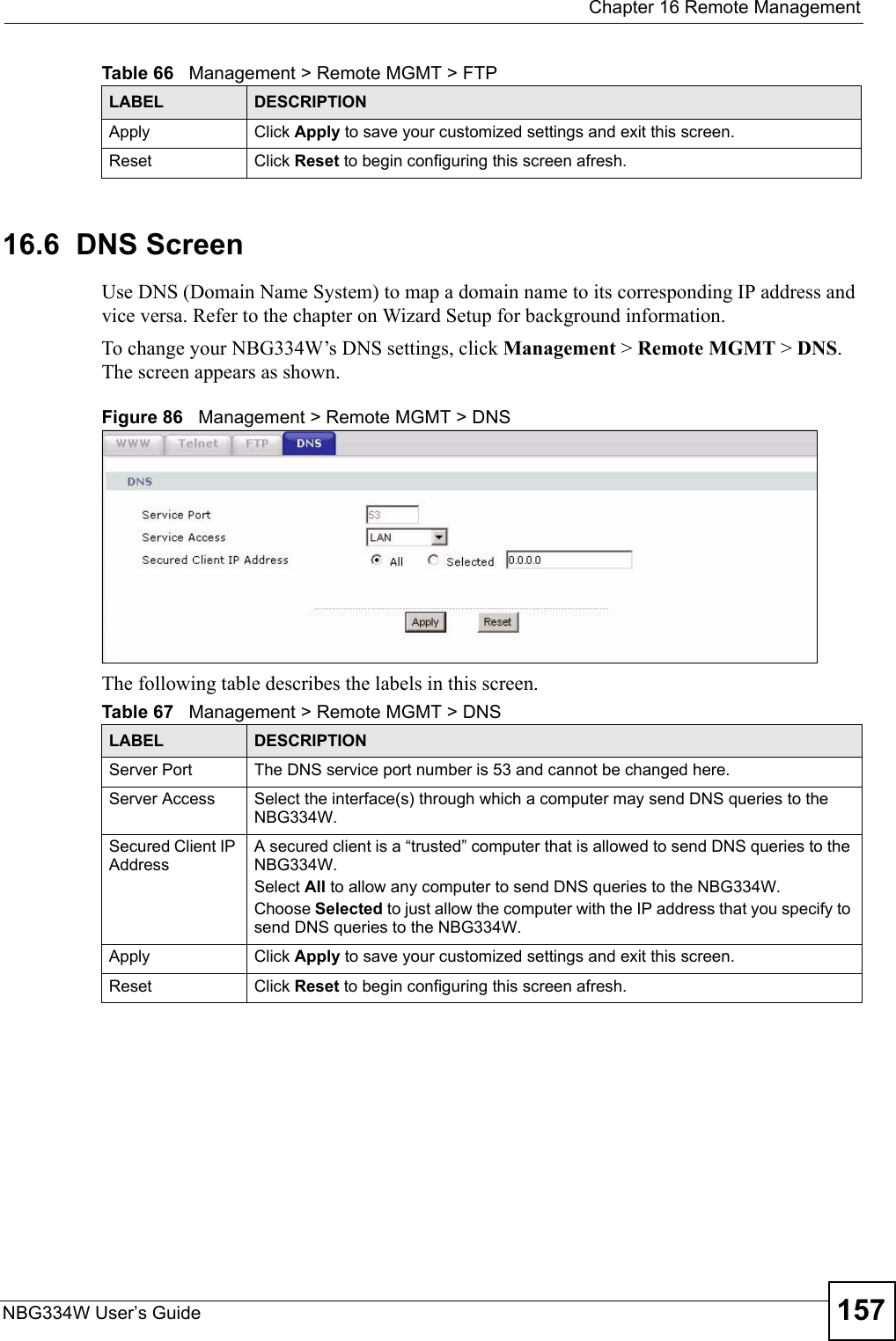
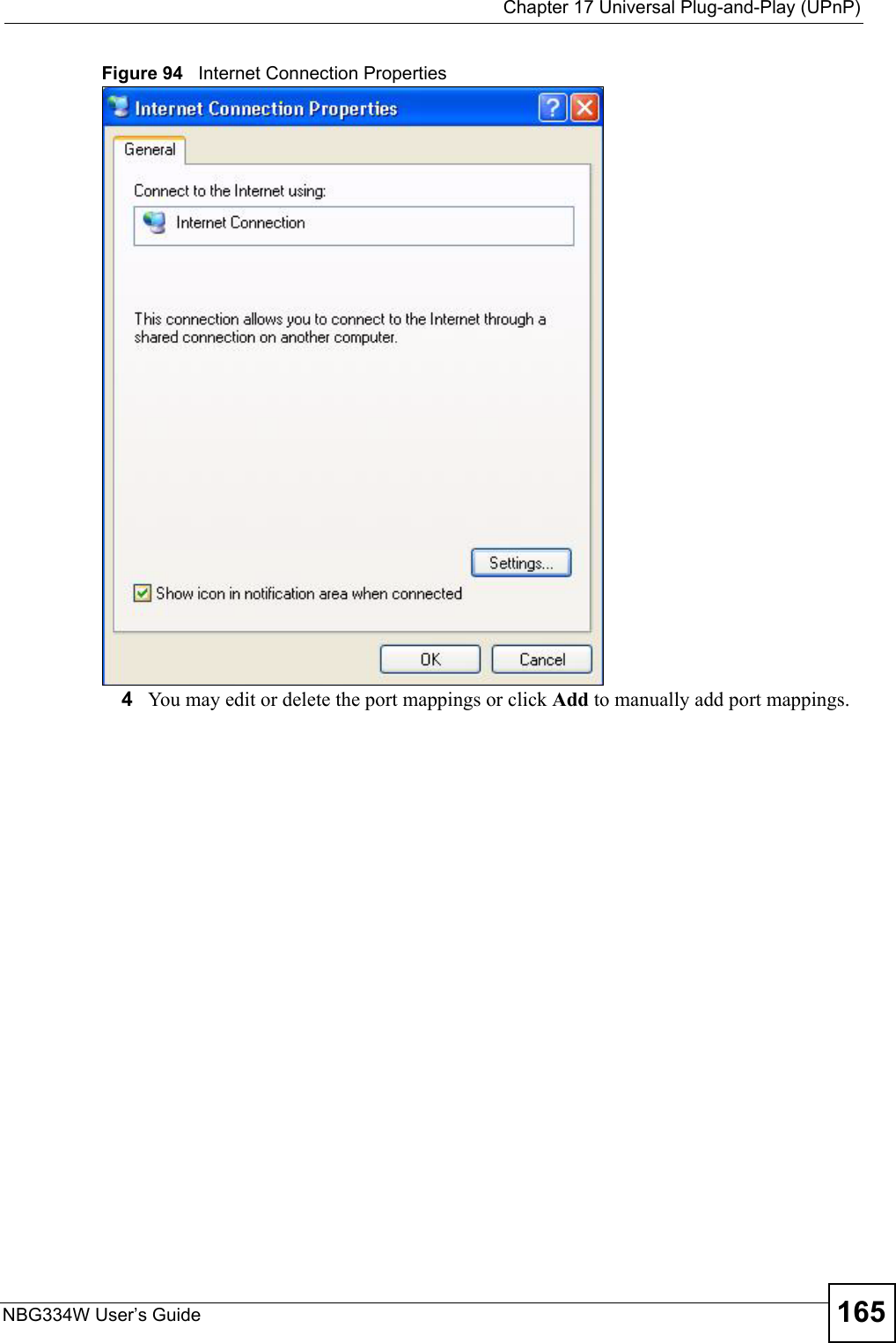
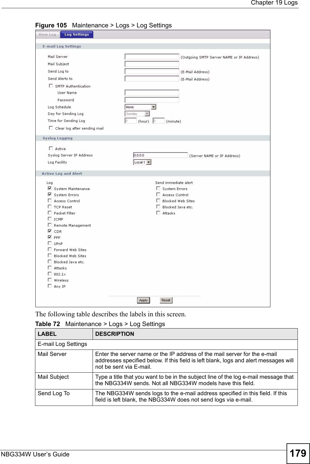
![Chapter 19 LogsNBG334W User’s Guide 183 Firewall session time out, sent TCP RSTThe router sent a TCP reset packet when a dynamic firewall session timed out.The default timeout values are as follows:ICMP idle timeout: 3 minutesUDP idle timeout: 3 minutesTCP connection (three way handshaking) timeout: 270 secondsTCP FIN-wait timeout: 2 MSL (Maximum Segment Lifetime set in the TCP header).TCP idle (established) timeout (s): 150 minutesTCP reset timeout: 10 secondsExceed MAX incomplete, sent TCP RSTThe router sent a TCP reset packet when the number of incomplete connections (TCP and UDP) exceeded the user-configured threshold. (Incomplete count is for all TCP and UDP connections through the firewall.)Note: When the number of incomplete connections (TCP + UDP) > “Maximum Incomplete High”, the router sends TCP RST packets for TCP connections and destroys TOS (firewall dynamic sessions) until incomplete connections < “Maximum Incomplete Low”.Access block, sent TCP RSTThe router sends a TCP RST packet and generates this log if you turn on the firewall TCP reset mechanism (via CI command: "sys firewall tcprst").Table 77 Packet Filter LogsLOG MESSAGE DESCRIPTION[TCP | UDP | ICMP | IGMP | Generic] packet filter matched (set:%d, rule:%d)Attempted access matched a configured filter rule (denoted by its set and rule number) and was blocked or forwarded according to the rule.Table 78 ICMP LogsLOG MESSAGE DESCRIPTIONFirewall default policy: ICMP <Packet Direction>, <type:%d>, <code:%d>ICMP access matched the default policy and was blocked or forwarded according to the user's setting. For type and code details, see Table 87 on page 188.Firewall rule [NOT] match: ICMP <Packet Direction>, <rule:%d>, <type:%d>, <code:%d>ICMP access matched (or didn’t match) a firewall rule (denoted by its number) and was blocked or forwarded according to the rule. For type and code details, see Table 87 on page 188.Triangle route packet forwarded: ICMPThe firewall allowed a triangle route session to pass through.Packet without a NAT table entry blocked: ICMPThe router blocked a packet that didn’t have a corresponding NAT table entry.Unsupported/out-of-order ICMP: ICMPThe firewall does not support this kind of ICMP packets or the ICMP packets are out of order.Router reply ICMP packet: ICMP The router sent an ICMP reply packet to the sender.Table 76 TCP Reset Logs (continued)LOG MESSAGE DESCRIPTION](https://usermanual.wiki/ZyXEL-Communications/NBG334W.Users-Manual-Part-3/User-Guide-823267-Page-84.png)
![Chapter 19 LogsNBG334W User’s Guide 185 %s: Proxy mode detectedThe router detected proxy mode in the packet.%s The content filter server responded that the web site is in the blocked category list, but it did not return the category type.%s:%s The content filter server responded that the web site is in the blocked category list, and returned the category type.%s(cache hit) The system detected that the web site is in the blocked list from the local cache, but does not know the category type.%s:%s(cache hit) The system detected that the web site is in blocked list from the local cache, and knows the category type.%s: Trusted Web site The web site is in a trusted domain.%s When the content filter is not on according to the time schedule or you didn't select the "Block Matched Web Site” check box, the system forwards the web content.Waiting content filter server timeoutThe external content filtering server did not respond within the timeout period.DNS resolving failed The NBG334W cannot get the IP address of the external content filtering via DNS query.Creating socket failed The NBG334W cannot issue a query because TCP/IP socket creation failed, port:port number.Connecting to content filter server failThe connection to the external content filtering server failed.License key is invalid The external content filtering license key is invalid.Table 83 Attack LogsLOG MESSAGE DESCRIPTIONattack [TCP | UDP | IGMP | ESP | GRE | OSPF]The firewall detected a TCP/UDP/IGMP/ESP/GRE/OSPF attack.attack ICMP (type:%d, code:%d)The firewall detected an ICMP attack. For type and code details, see Table 87 on page 188.land [TCP | UDP | IGMP | ESP | GRE | OSPF]The firewall detected a TCP/UDP/IGMP/ESP/GRE/OSPF land attack.land ICMP (type:%d, code:%d)The firewall detected an ICMP land attack. For type and code details, see Table 87 on page 188.ip spoofing - WAN [TCP | UDP | IGMP | ESP | GRE | OSPF]The firewall detected an IP spoofing attack on the WAN port.ip spoofing - WAN ICMP (type:%d, code:%d)The firewall detected an ICMP IP spoofing attack on the WAN port. For type and code details, see Table 87 on page 188.icmp echo: ICMP (type:%d, code:%d)The firewall detected an ICMP echo attack. For type and code details, see Table 87 on page 188.syn flood TCP The firewall detected a TCP syn flood attack.ports scan TCP The firewall detected a TCP port scan attack.teardrop TCP The firewall detected a TCP teardrop attack.Table 82 Content Filtering Logs (continued)LOG MESSAGE DESCRIPTION](https://usermanual.wiki/ZyXEL-Communications/NBG334W.Users-Manual-Part-3/User-Guide-823267-Page-86.png)
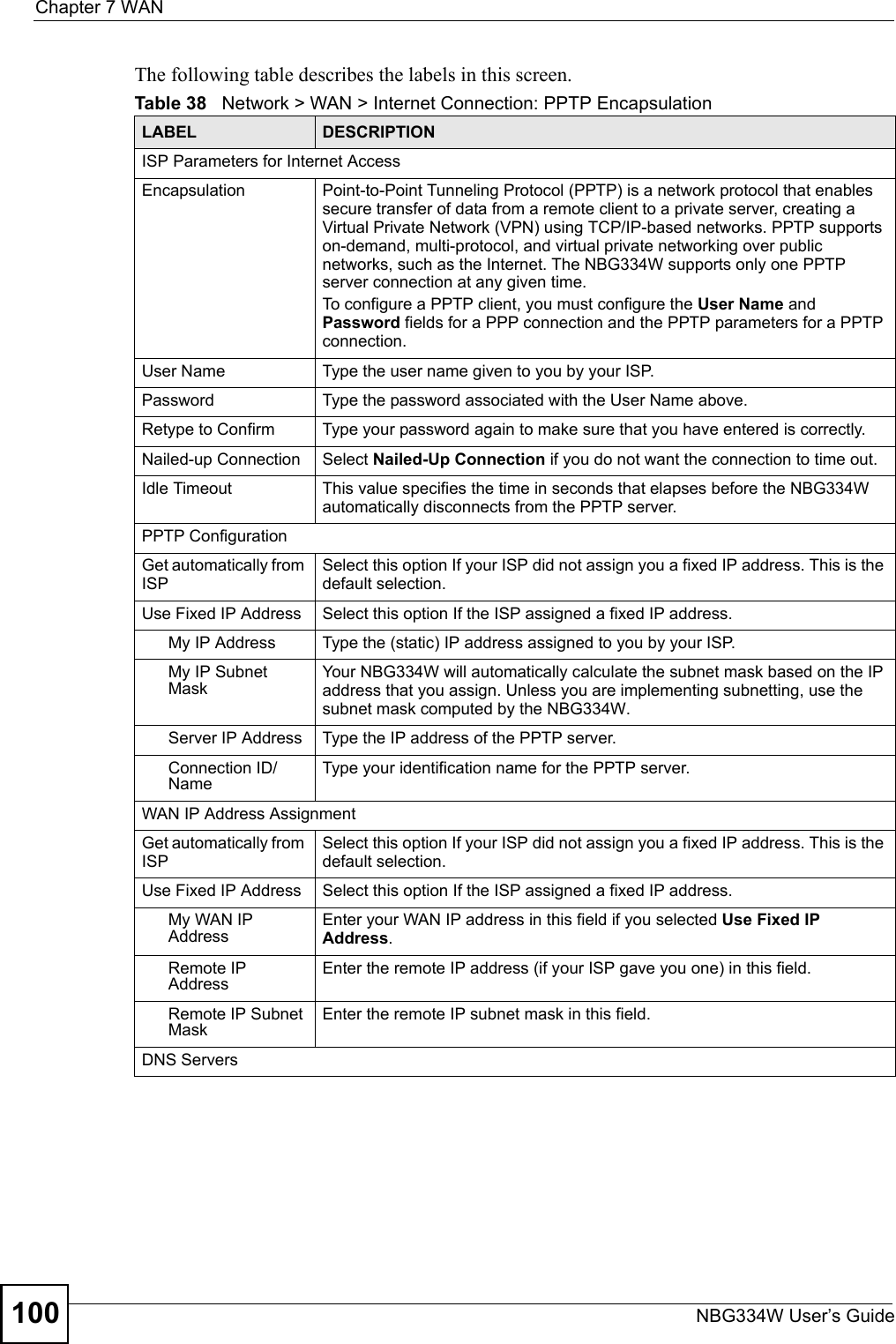
![Chapter 19 LogsNBG334W User’s Guide186 teardrop UDP The firewall detected an UDP teardrop attack.teardrop ICMP (type:%d, code:%d)The firewall detected an ICMP teardrop attack. For type and code details, see Table 87 on page 188.illegal command TCP The firewall detected a TCP illegal command attack.NetBIOS TCP The firewall detected a TCP NetBIOS attack.ip spoofing - no routing entry [TCP | UDP | IGMP | ESP | GRE | OSPF]The firewall classified a packet with no source routing entry as an IP spoofing attack.ip spoofing - no routing entry ICMP (type:%d, code:%d)The firewall classified an ICMP packet with no source routing entry as an IP spoofing attack.vulnerability ICMP (type:%d, code:%d)The firewall detected an ICMP vulnerability attack. For type and code details, see Table 87 on page 188.traceroute ICMP (type:%d, code:%d)The firewall detected an ICMP traceroute attack. For type and code details, see Table 87 on page 188.Table 84 PKI LogsLOG MESSAGE DESCRIPTIONEnrollment successful The SCEP online certificate enrollment was successful. The Destination field records the certification authority server IP address and port.Enrollment failed The SCEP online certificate enrollment failed. The Destination field records the certification authority server’s IP address and port.Failed to resolve <SCEP CA server url>The SCEP online certificate enrollment failed because the certification authority server’s address cannot be resolved.Enrollment successful The CMP online certificate enrollment was successful. The Destination field records the certification authority server’s IP address and port.Enrollment failed The CMP online certificate enrollment failed. The Destination field records the certification authority server’s IP address and port.Failed to resolve <CMP CA server url>The CMP online certificate enrollment failed because the certification authority server’s IP address cannot be resolved.Rcvd ca cert: <subject name>The router received a certification authority certificate, with subject name as recorded, from the LDAP server whose IP address and port are recorded in the Source field.Rcvd user cert: <subject name>The router received a user certificate, with subject name as recorded, from the LDAP server whose IP address and port are recorded in the Source field.Rcvd CRL <size>: <issuer name>The router received a CRL (Certificate Revocation List), with size and issuer name as recorded, from the LDAP server whose IP address and port are recorded in the Source field.Rcvd ARL <size>: <issuer name>The router received an ARL (Authority Revocation List), with size and issuer name as recorded, from the LDAP server whose address and port are recorded in the Source field.Table 83 Attack Logs (continued)LOG MESSAGE DESCRIPTION](https://usermanual.wiki/ZyXEL-Communications/NBG334W.Users-Manual-Part-3/User-Guide-823267-Page-87.png)