ZyXEL Communications NBG334W Wireless Firewall Router User Manual NBG334W User s Guide
ZyXEL Communications Corporation Wireless Firewall Router NBG334W User s Guide
Contents
- 1. Users Manual Part 1
- 2. Users Manual Part 2
- 3. Users Manual Part 3
- 4. Users Manual Part 4
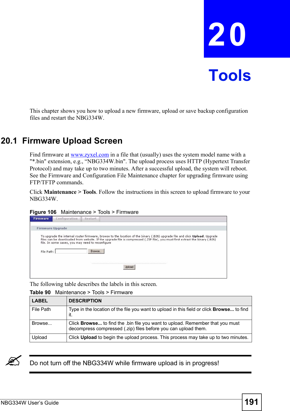
Users Manual Part 4


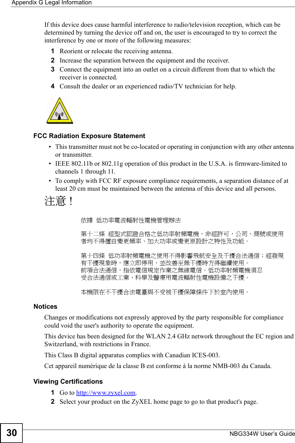
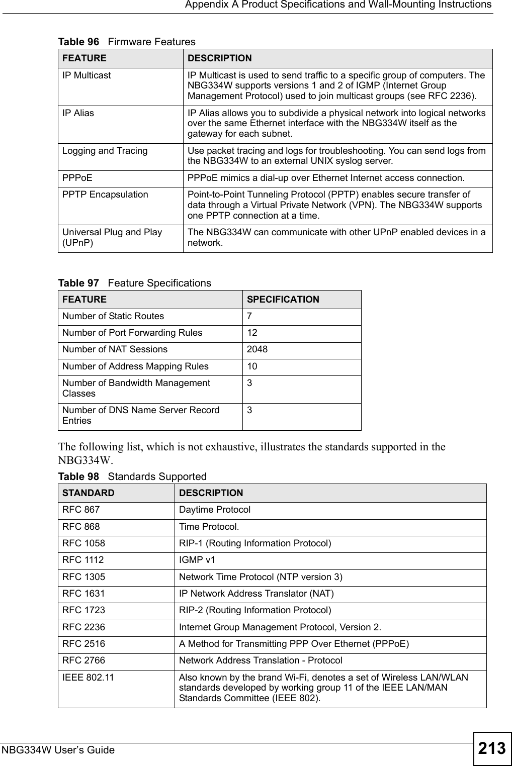
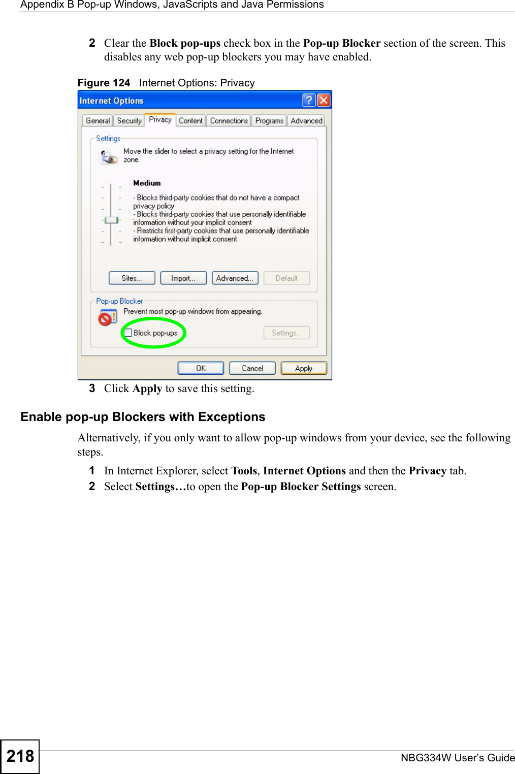
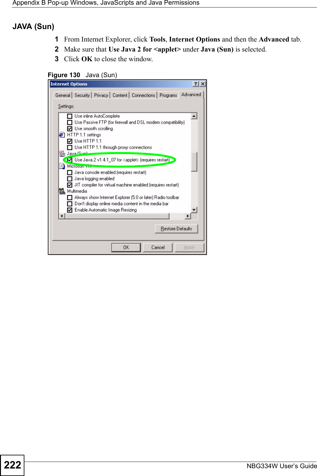
![Chapter 23 TroubleshootingNBG334W User’s Guide 2052Check the hardware connections, and make sure the LEDs are behaving as expected. See the Quick Start Guide. 3Make sure your Internet browser does not block pop-up windows and has JavaScripts and Java enabled. See Appendix B on page 217.4Make sure your computer is in the same subnet as the NBG334W. (If you know that there are routers between your computer and the NBG334W, skip this step.)• If there is a DHCP server on your network, make sure your computer is using a dynamic IP address. See Section 7.3 on page 102. • If there is no DHCP server on your network, make sure your computer’s IP address is in the same subnet as the NBG334W. See Section 7.3 on page 102.5Reset the device to its factory defaults, and try to access the NBG334W with the default IP address. See Section 7.3 on page 102. 6If the problem continues, contact the network administrator or vendor, or try one of the advanced suggestions.Advanced Suggestions• Try to access the NBG334W using another service, such as Telnet. If you can access the NBG334W, check the remote management settings and firewall rules to find out why the NBG334W does not respond to HTTP.• If your computer is connected to the WA N port or is connected wirelessly, use a computer that is connected to a LAN/ETHERNET port.VI can see the Login screen, but I cannot log in to the NBG334W.1Make sure you have entered the password correctly. The default password is 1234. This field is case-sensitive, so make sure [Caps Lock] is not on. 2You cannot log in to the web configurator while someone is using Telnet to access the NBG334W. Log out of the NBG334W in the other session, or ask the person who is logged in to log out. 3Disconnect and re-connect the power adaptor or cord to the NBG334W. 4If this does not work, you have to reset the device to its factory defaults. See Section 23.4 on page 207.VI cannot Telnet to the NBG334W. See the troubleshooting suggestions for I cannot see or access the Login screen in the web configurator. Ignore the suggestions about your browser.VI cannot use FTP to upload / download the configuration file. / I cannot use FTP to upload new firmware.](https://usermanual.wiki/ZyXEL-Communications/NBG334W.Users-Manual-Part-4/User-Guide-823268-Page-16.png)
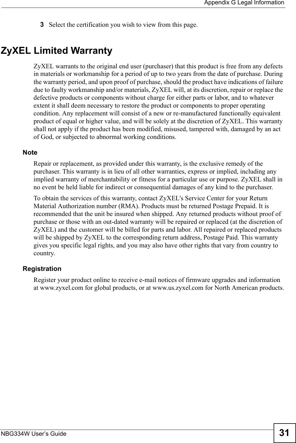
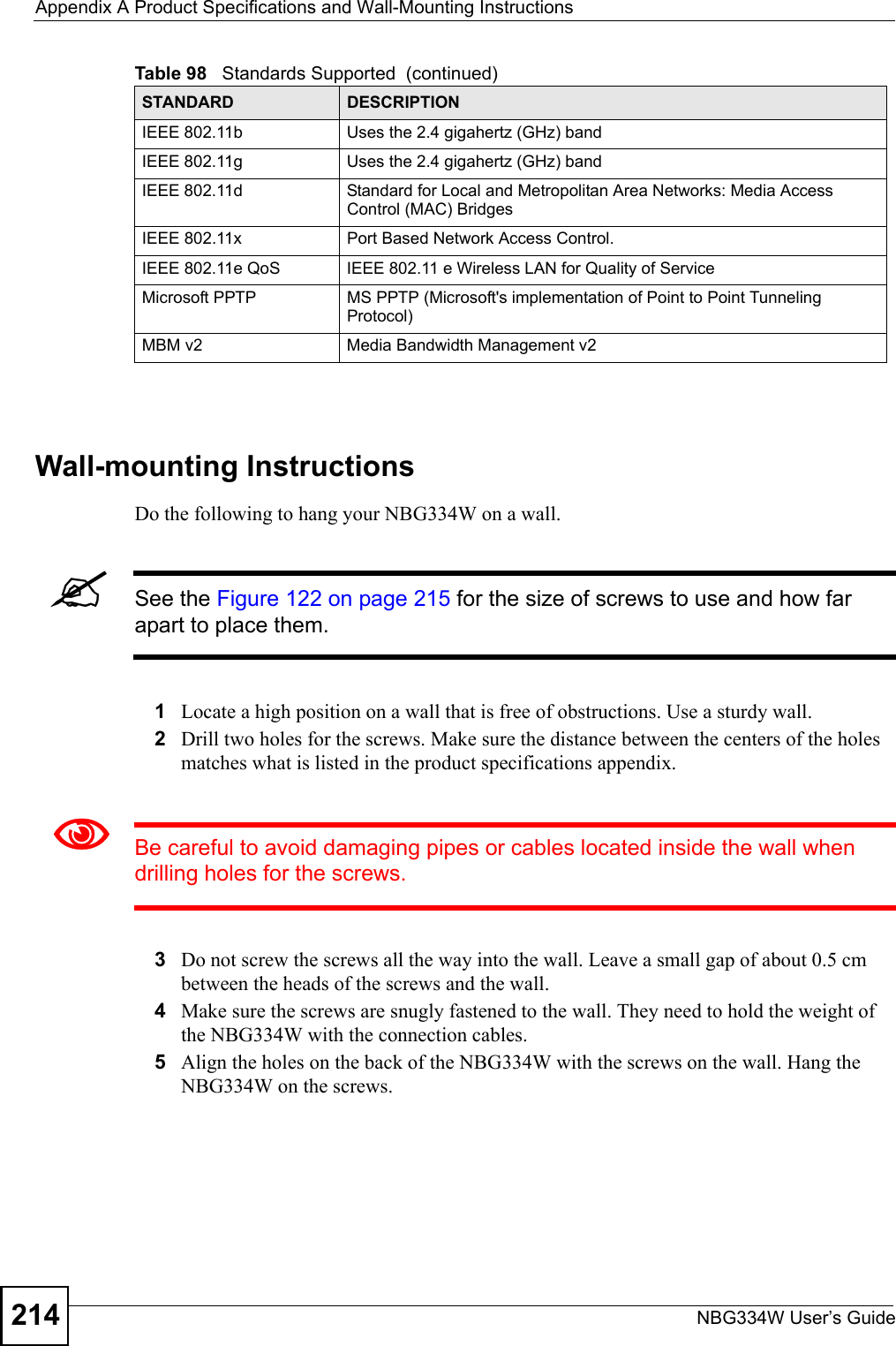
![Chapter 23 TroubleshootingNBG334W User’s Guide206See the troubleshooting suggestions for I cannot see or access the Login screen in the web configurator. Ignore the suggestions about your browser.23.3 Internet AccessVI cannot access the Internet.1Check the hardware connections, and make sure the LEDs are behaving as expected. See the Quick Start Guide.2Make sure you entered your ISP account information correctly in the wizard. These fields are case-sensitive, so make sure [Caps Lock] is not on.3If you are trying to access the Internet wirelessly, make sure the wireless settings in the wireless client are the same as the settings in the AP. 4Disconnect all the cables from your device, and follow the directions in the Quick Start Guide again. 5Go to Maintenance > Sys OP Mode > General. Check your System Operation Mode setting. • Select Router if your device routes traffic between a local network and another network such as the Internet. • Select Access Point if your device bridges traffic between clients on the same network. 6If the problem continues, contact your ISP.VI cannot access the Internet anymore. I had access to the Internet (with the NBG334W), but my Internet connection is not available anymore.1Check the hardware connections, and make sure the LEDs are behaving as expected. See the Quick Start Guide and Section 1.7 on page 31. 2Reboot the NBG334W.3If the problem continues, contact your ISP. VThe Internet connection is slow or intermittent.1There might be a lot of traffic on the network. Look at the LEDs, and check Section 1.7 on page 31. If the NBG334W is sending or receiving a lot of information, try closing some programs that use the Internet, especially peer-to-peer applications. 2Check the signal strength. If the signal strength is low, try moving the NBG334W closer to the AP if possible, and look around to see if there are any devices that might be](https://usermanual.wiki/ZyXEL-Communications/NBG334W.Users-Manual-Part-4/User-Guide-823268-Page-17.png)

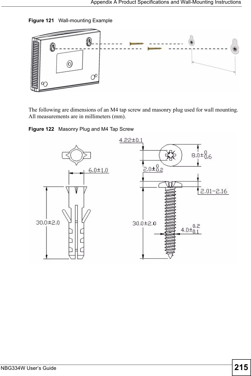

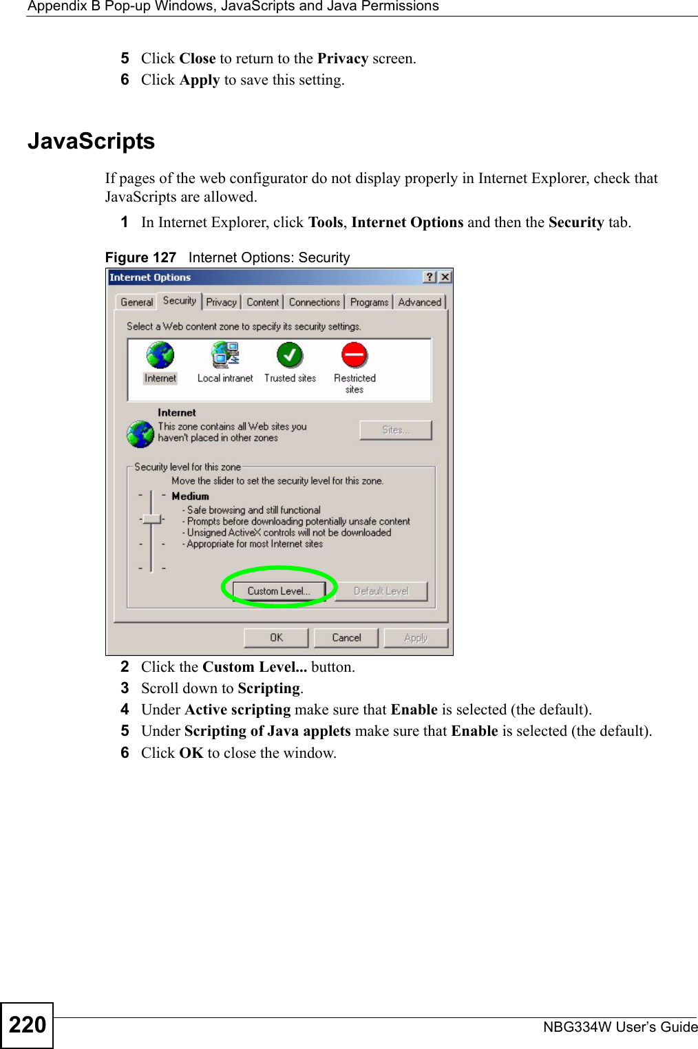
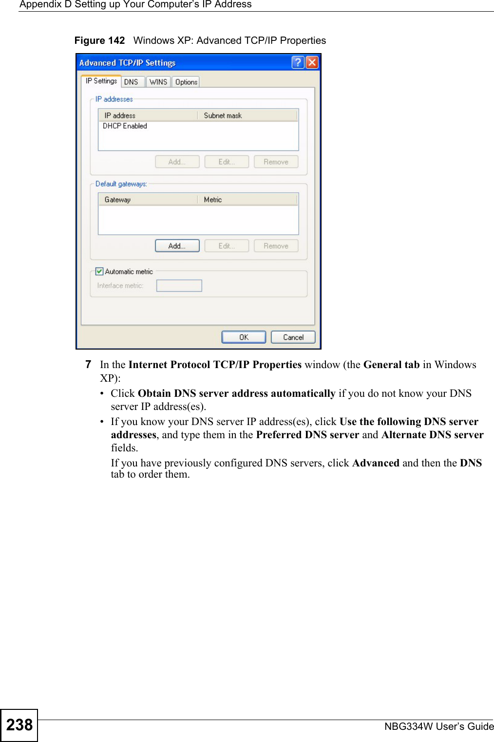
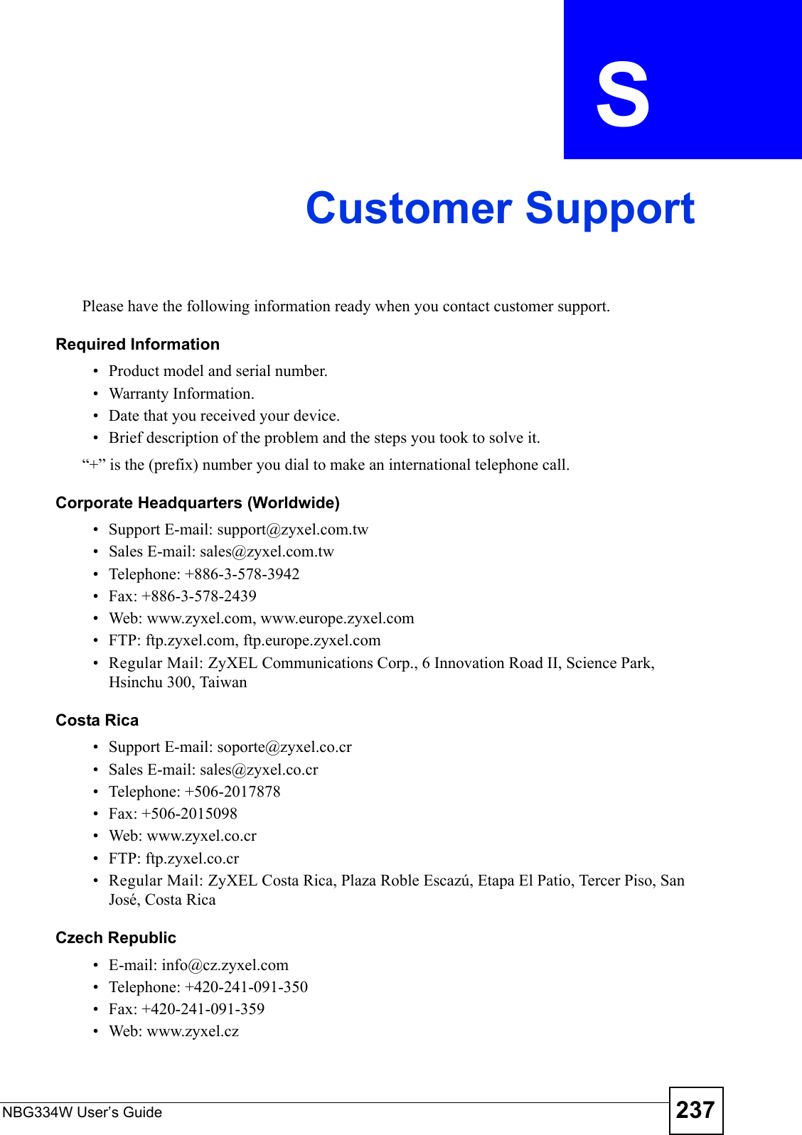
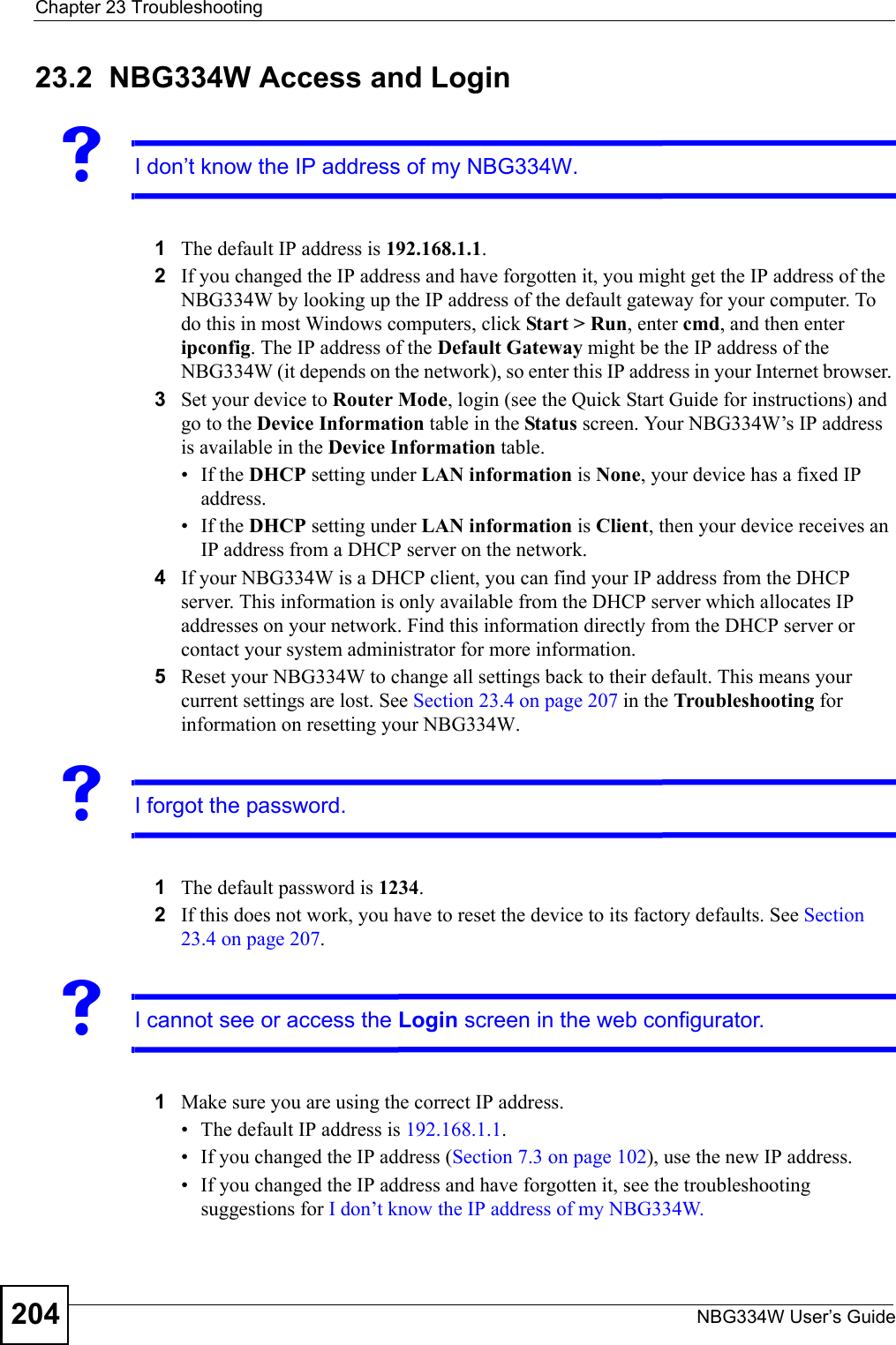
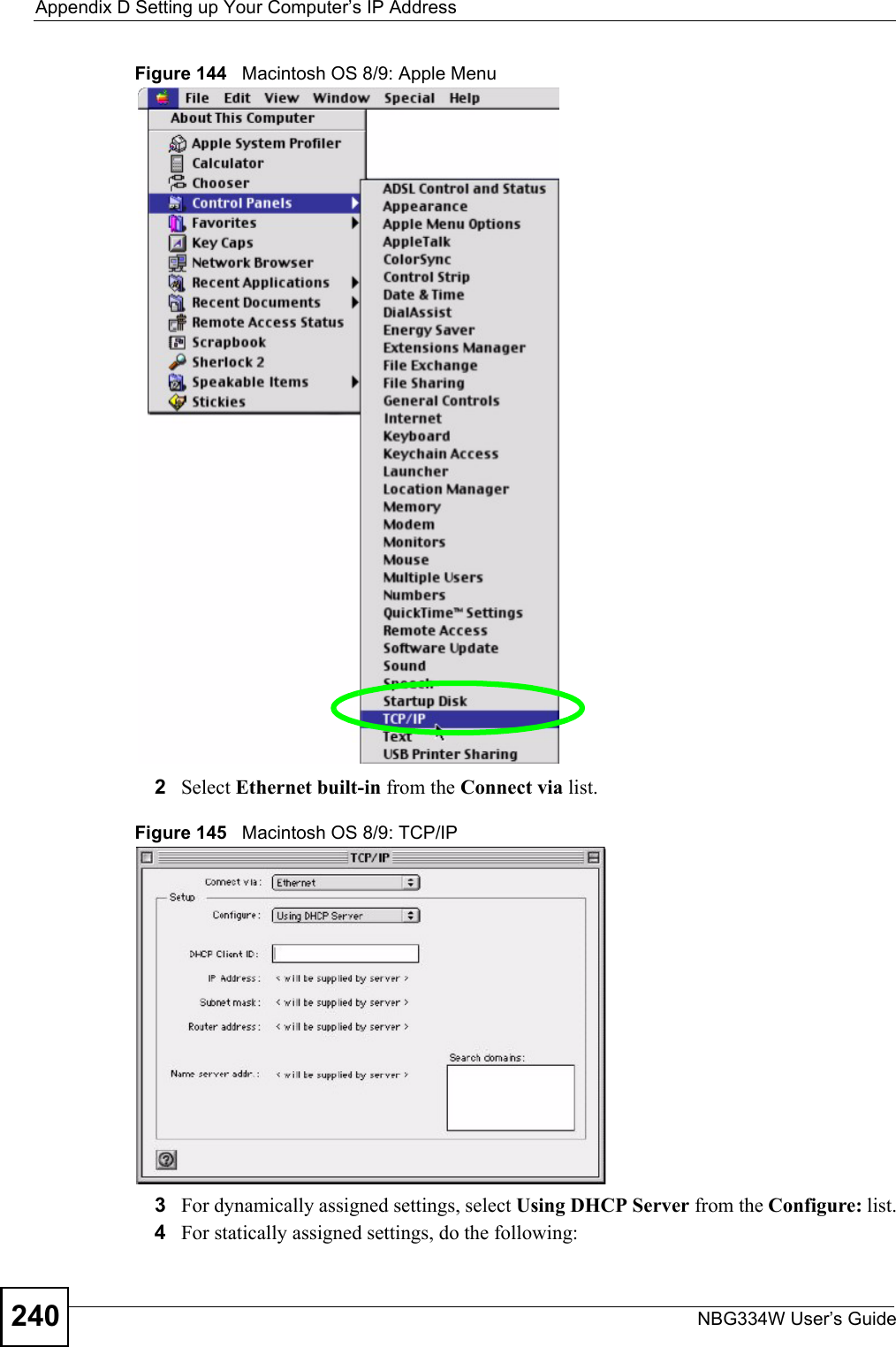
![Appendix D Setting up Your Computer’s IP AddressNBG334W User’s Guide 239Figure 143 Windows XP: Internet Protocol (TCP/IP) Properties8Click OK to close the Internet Protocol (TCP/IP) Properties window.9Click Close (OK in Windows 2000/NT) to close the Local Area Connection Properties window.10 Close the Network Connections window (Network and Dial-up Connections in Windows 2000/NT).11 Turn on your Prestige and restart your computer (if prompted).Verifying Settings1Click Start, All Programs, Accessories and then Command Prompt.2In the Command Prompt window, type "ipconfig" and then press [ENTER]. You can also open Network Connections, right-click a network connection, click Status and then click the Support tab.Macintosh OS 8/9 1Click the Apple menu, Control Panel and double-click TCP/IP to open the TCP/IP Control Panel.](https://usermanual.wiki/ZyXEL-Communications/NBG334W.Users-Manual-Part-4/User-Guide-823268-Page-50.png)
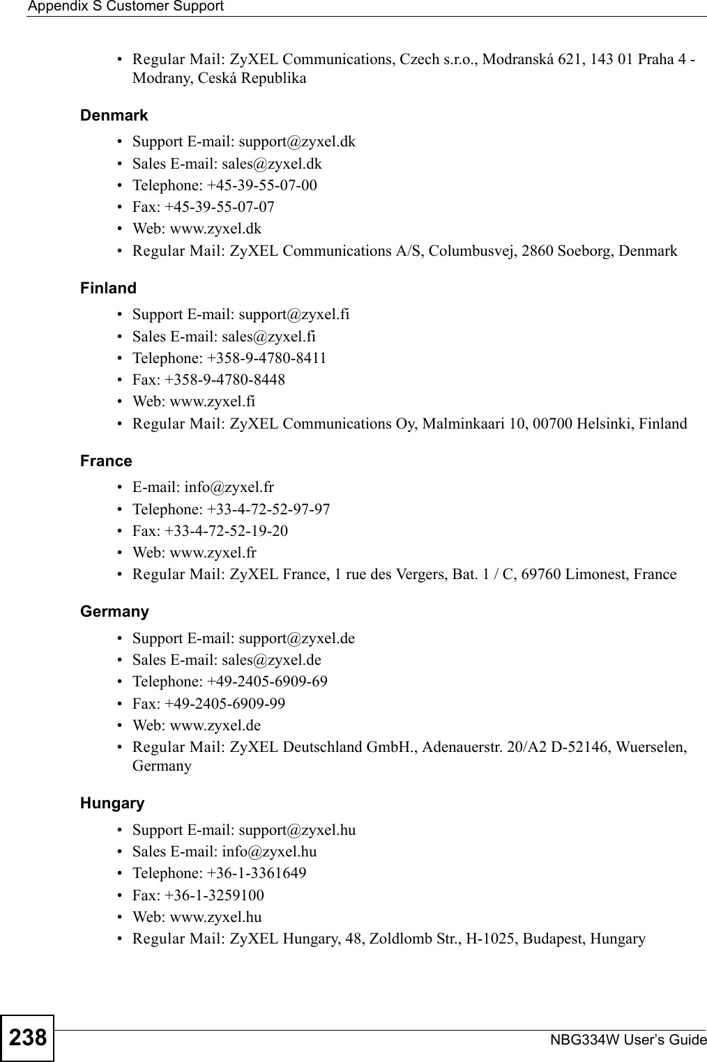
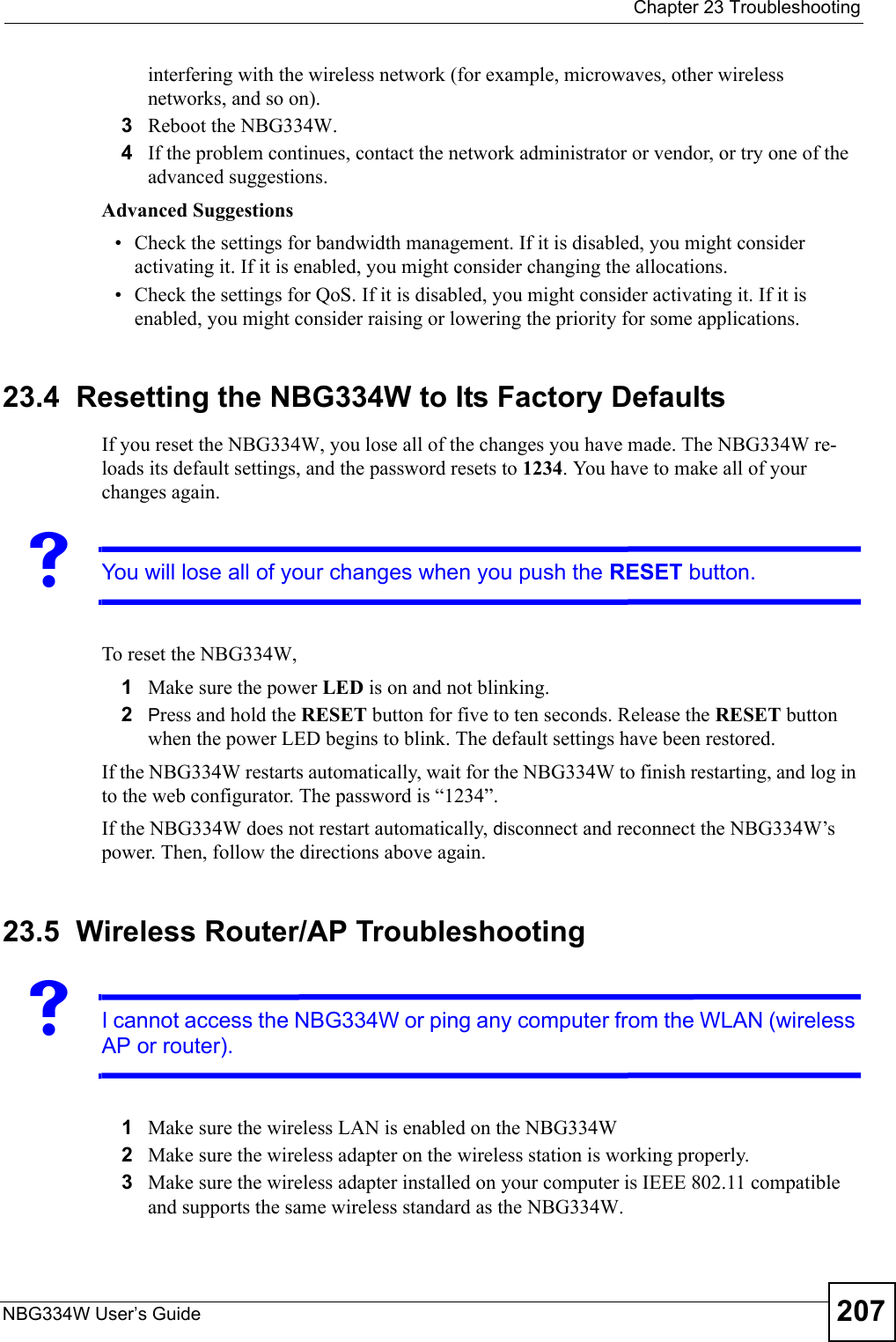
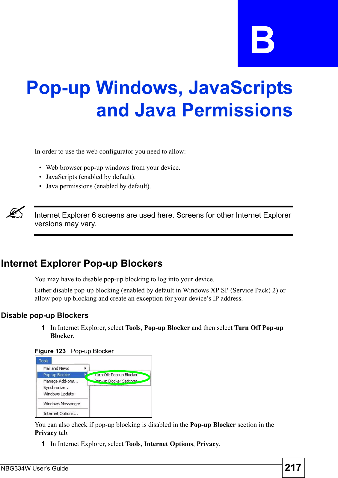
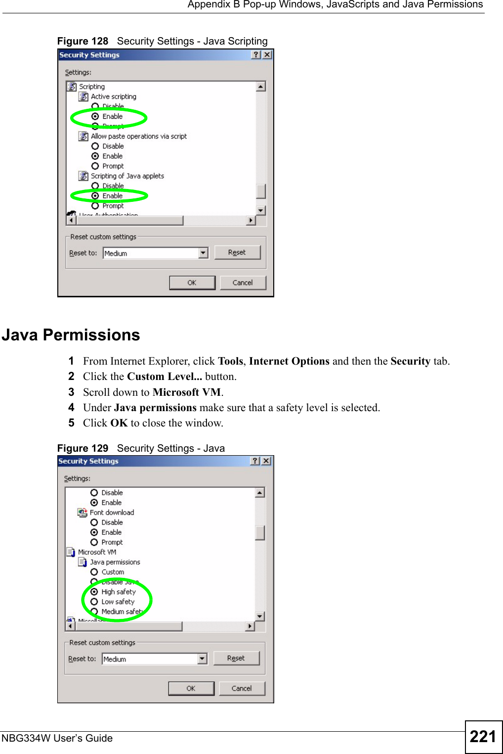
![Appendix D Setting up Your Computer’s IP AddressNBG334W User’s Guide2462If you know your DNS server IP address(es), enter the DNS server information in the resolv.conf file in the /etc directory. The following figure shows an example where two DNS server IP addresses are specified.Figure 154 Red Hat 9.0: DNS Settings in resolv.conf 3After you edit and save the configuration files, you must restart the network card. Enter./network restart in the /etc/rc.d/init.d directory. The following figure shows an example.Figure 155 Red Hat 9.0: Restart Ethernet Card 23.6.1 Verifying SettingsEnter ifconfig in a terminal screen to check your TCP/IP properties. Figure 156 Red Hat 9.0: Checking TCP/IP Properties nameserver 172.23.5.1nameserver 172.23.5.2[root@localhost init.d]# network restartShutting down interface eth0: [OK]Shutting down loopback interface: [OK]Setting network parameters: [OK]Bringing up loopback interface: [OK]Bringing up interface eth0: [OK][root@localhost]# ifconfig eth0 Link encap:Ethernet HWaddr 00:50:BA:72:5B:44 inet addr:172.23.19.129 Bcast:172.23.19.255 Mask:255.255.255.0 UP BROADCAST RUNNING MULTICAST MTU:1500 Metric:1 RX packets:717 errors:0 dropped:0 overruns:0 frame:0 TX packets:13 errors:0 dropped:0 overruns:0 carrier:0 collisions:0 txqueuelen:100 RX bytes:730412 (713.2 Kb) TX bytes:1570 (1.5 Kb) Interrupt:10 Base address:0x1000 [root@localhost]#](https://usermanual.wiki/ZyXEL-Communications/NBG334W.Users-Manual-Part-4/User-Guide-823268-Page-57.png)