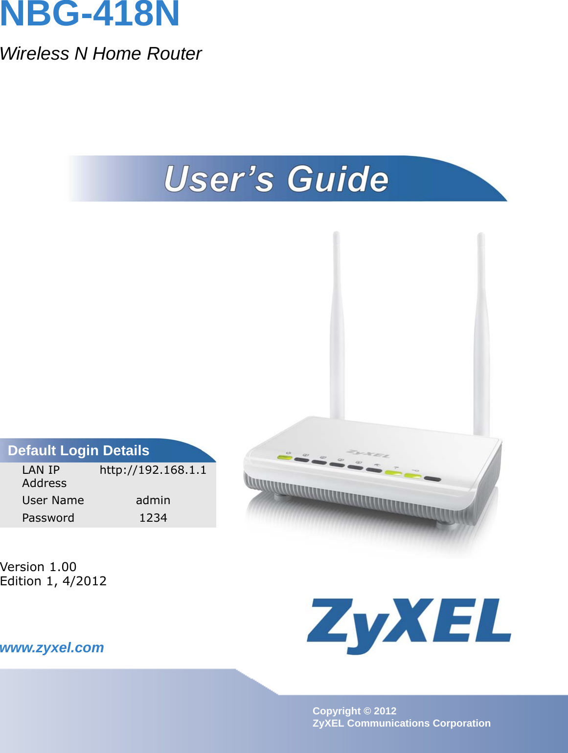
ZyXEL Communications NBG418N Wireless N Home Router Model No.: NBG-418N User Manual Book

ZyXEL Communications Corporation Wireless N Home Router Model No.: NBG-418N Book

Contents

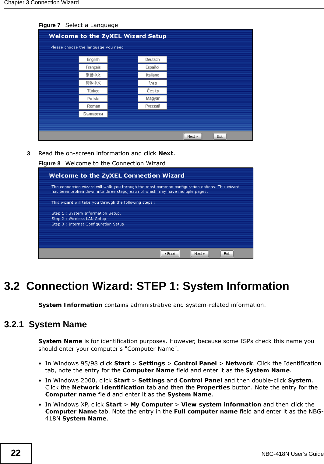
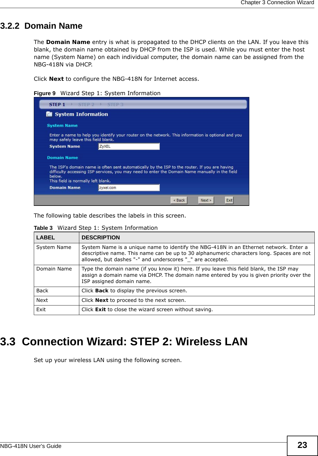
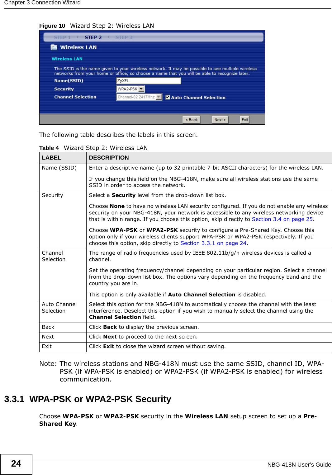
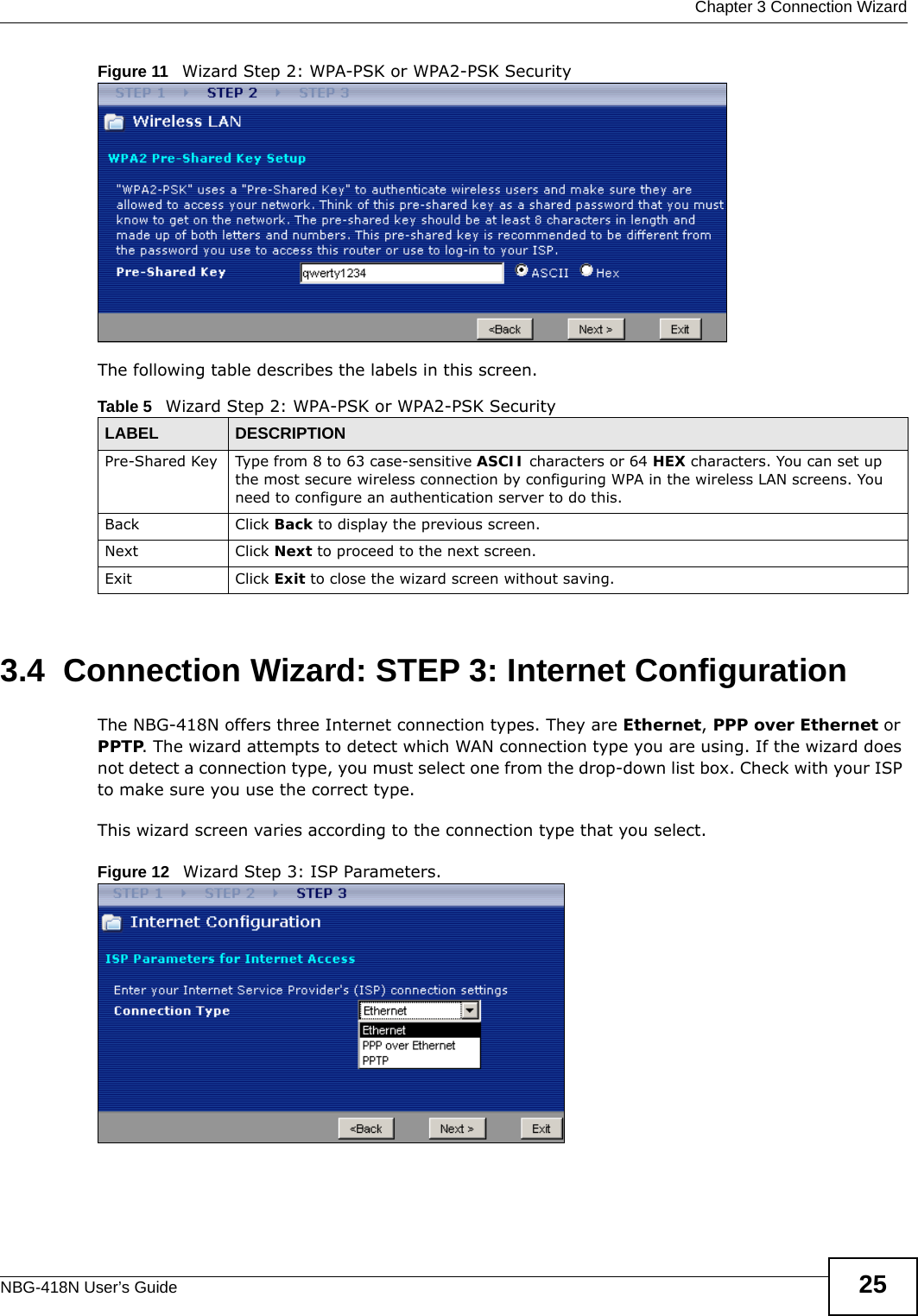
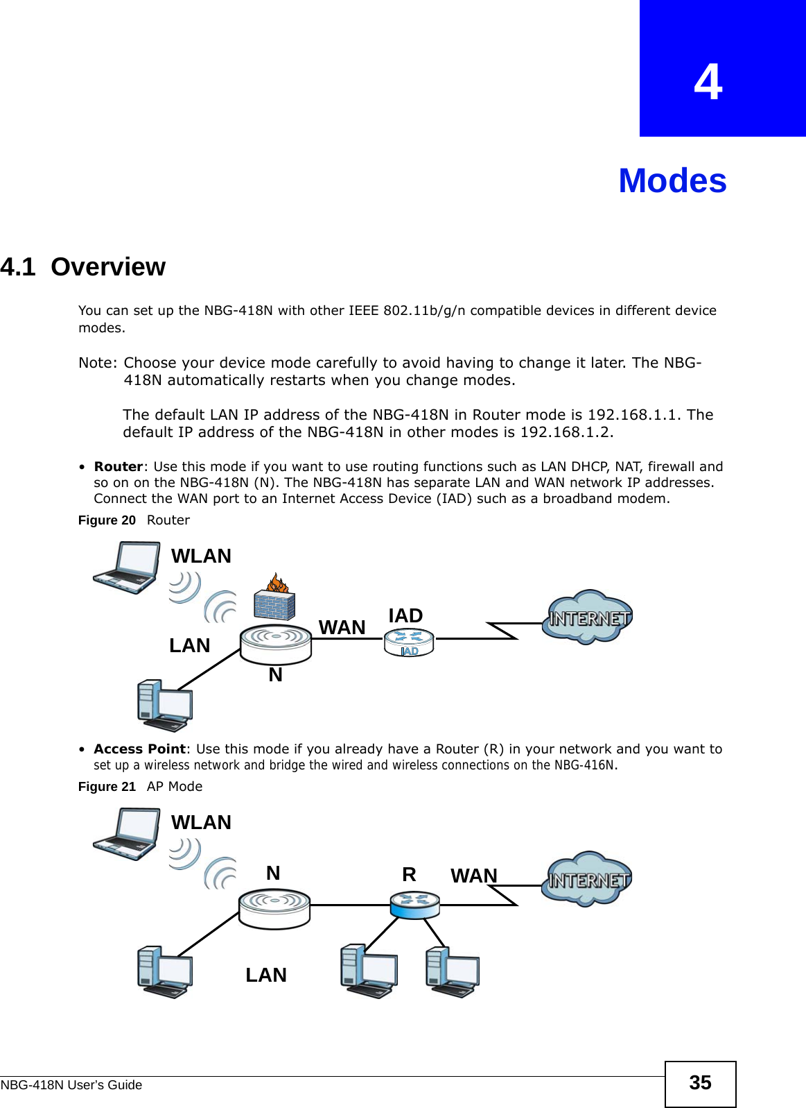
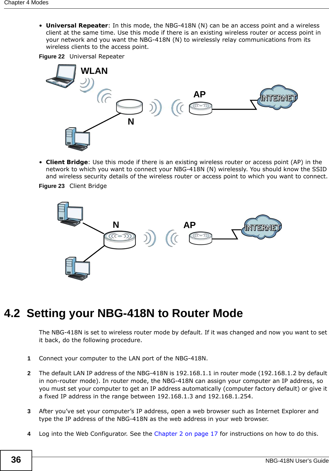
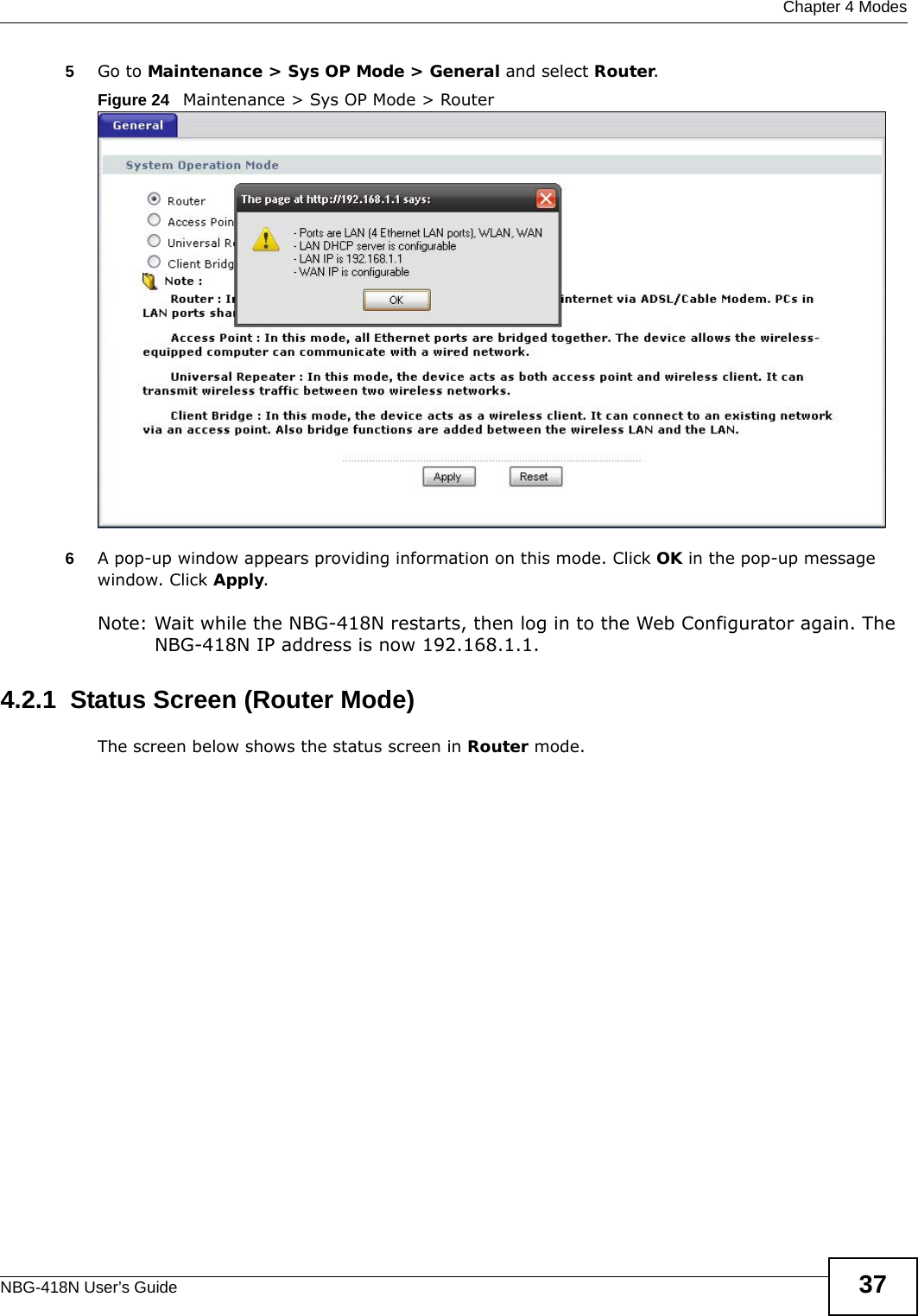
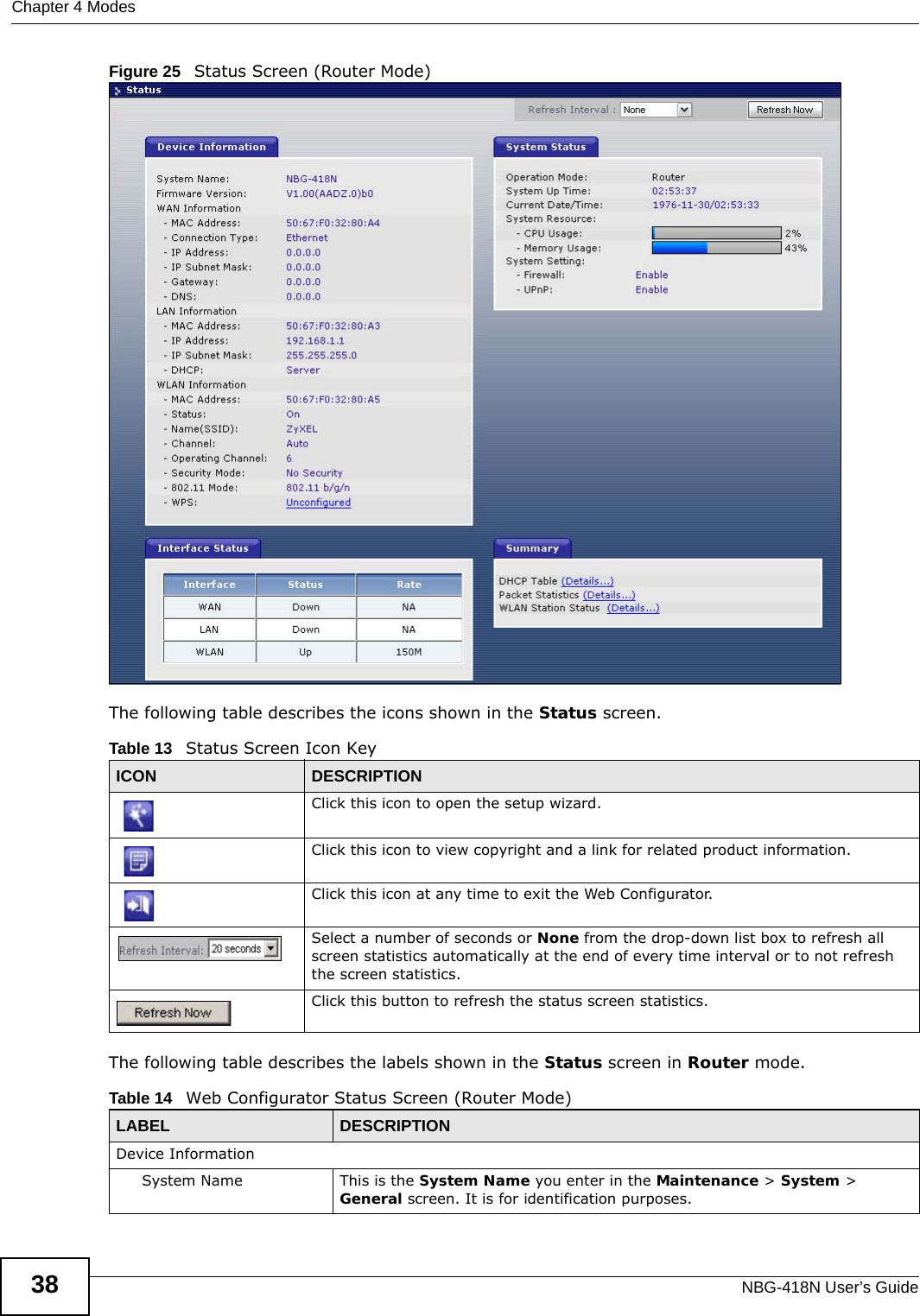
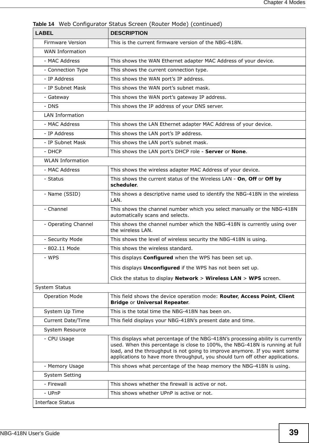
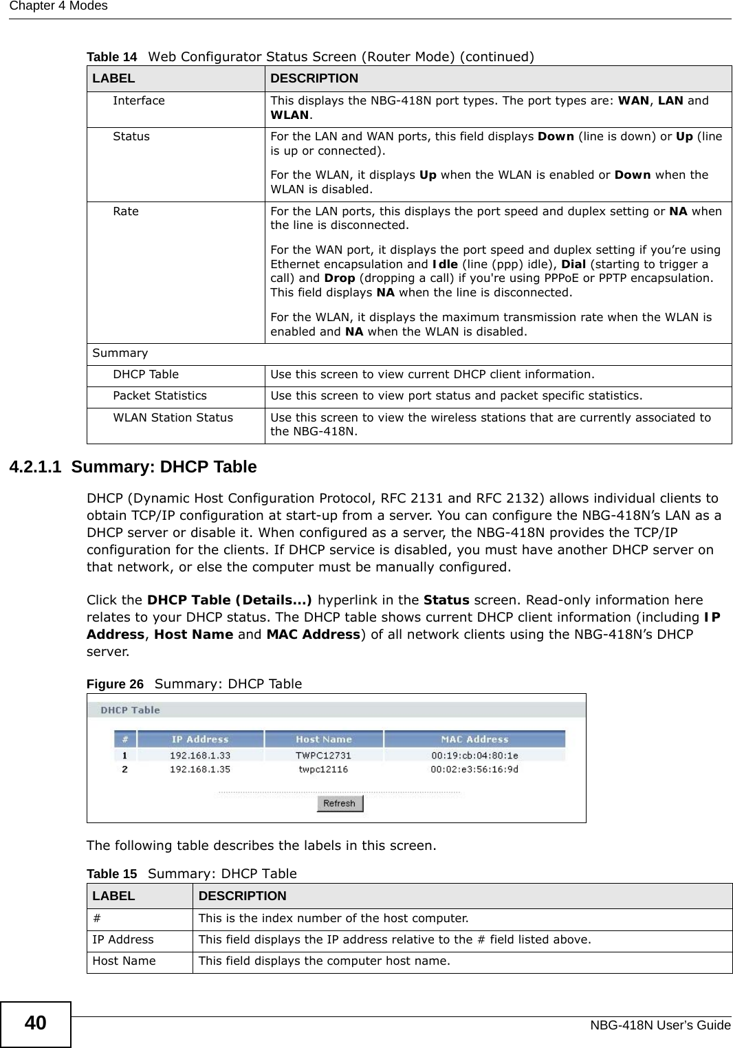
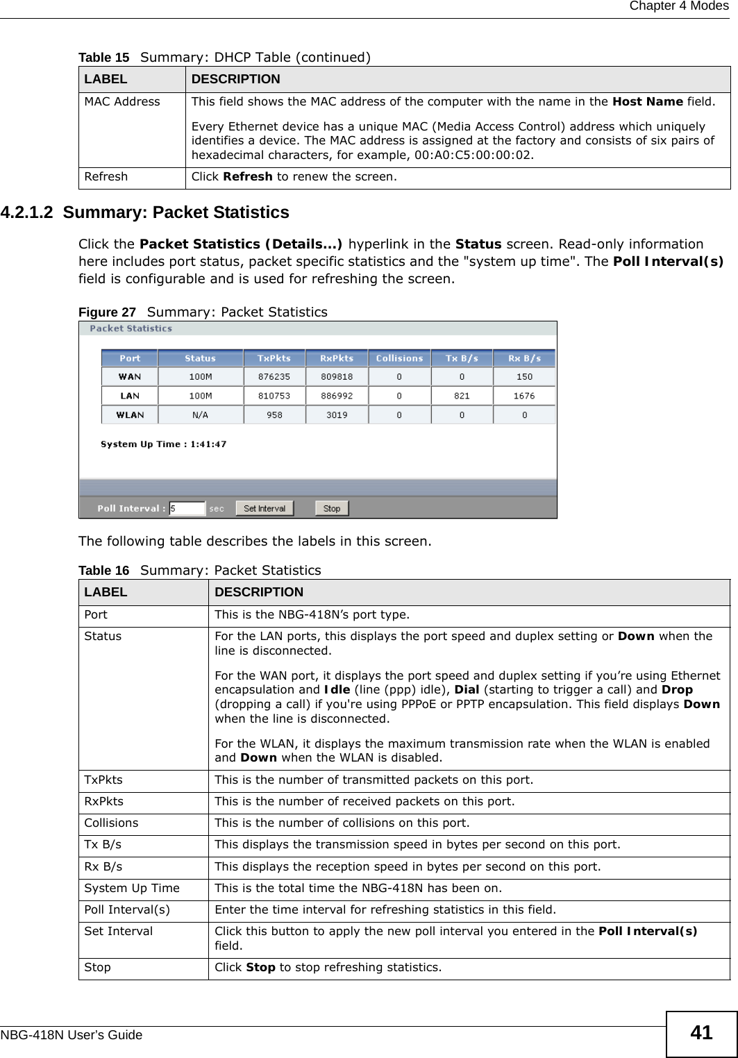
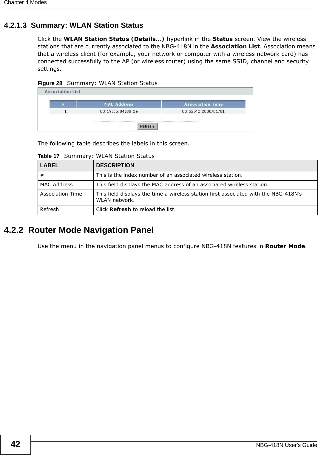
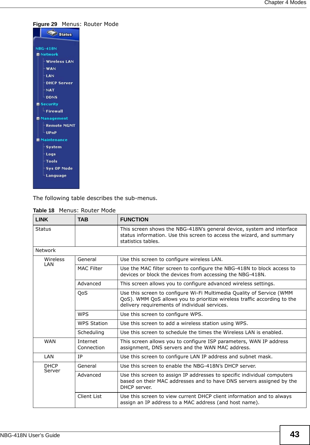
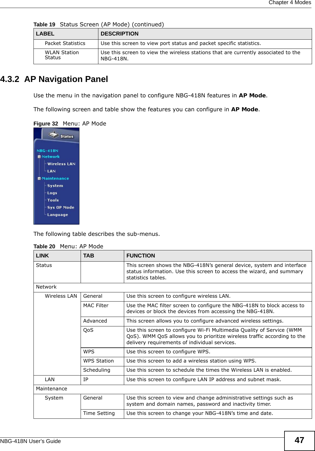
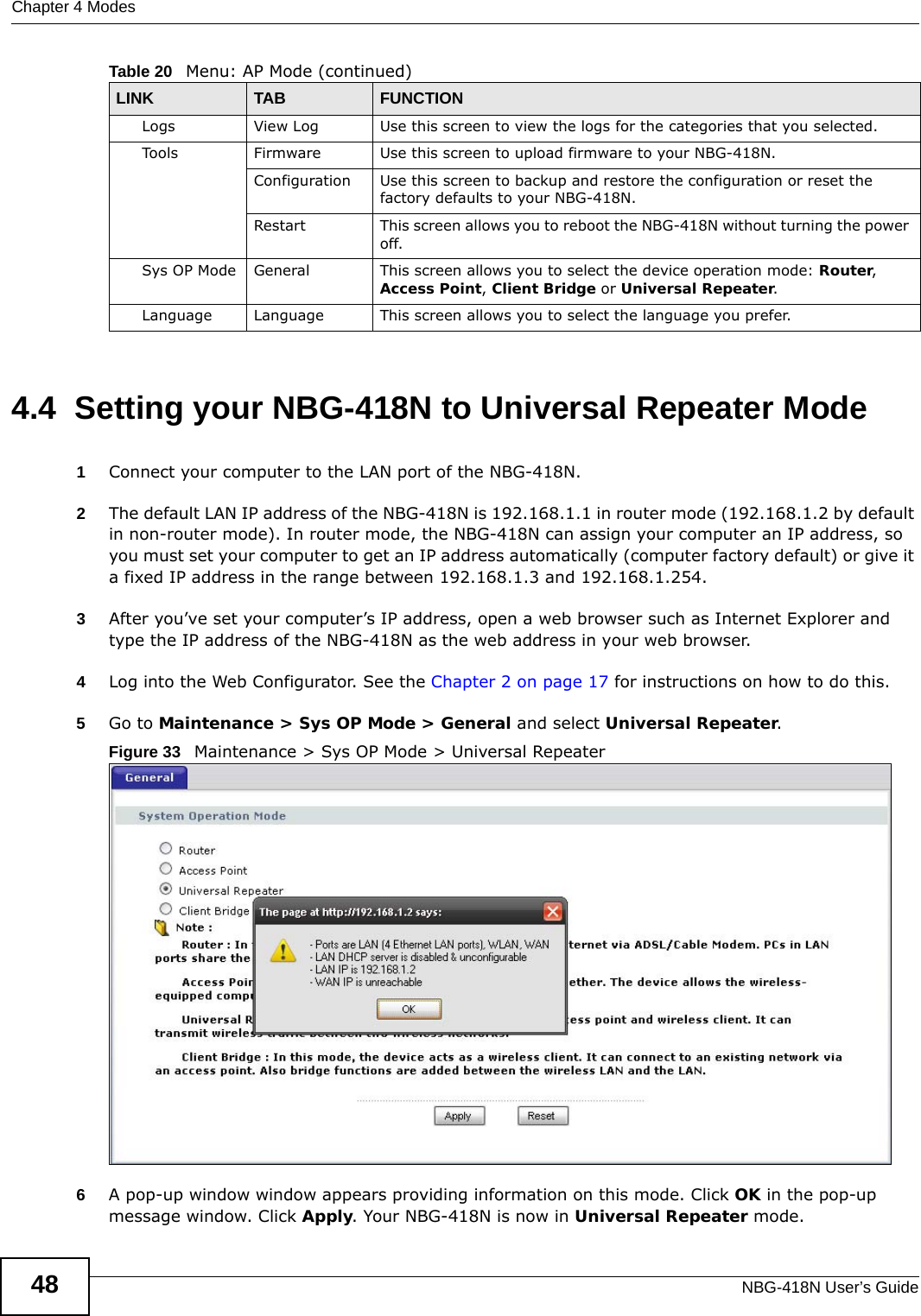
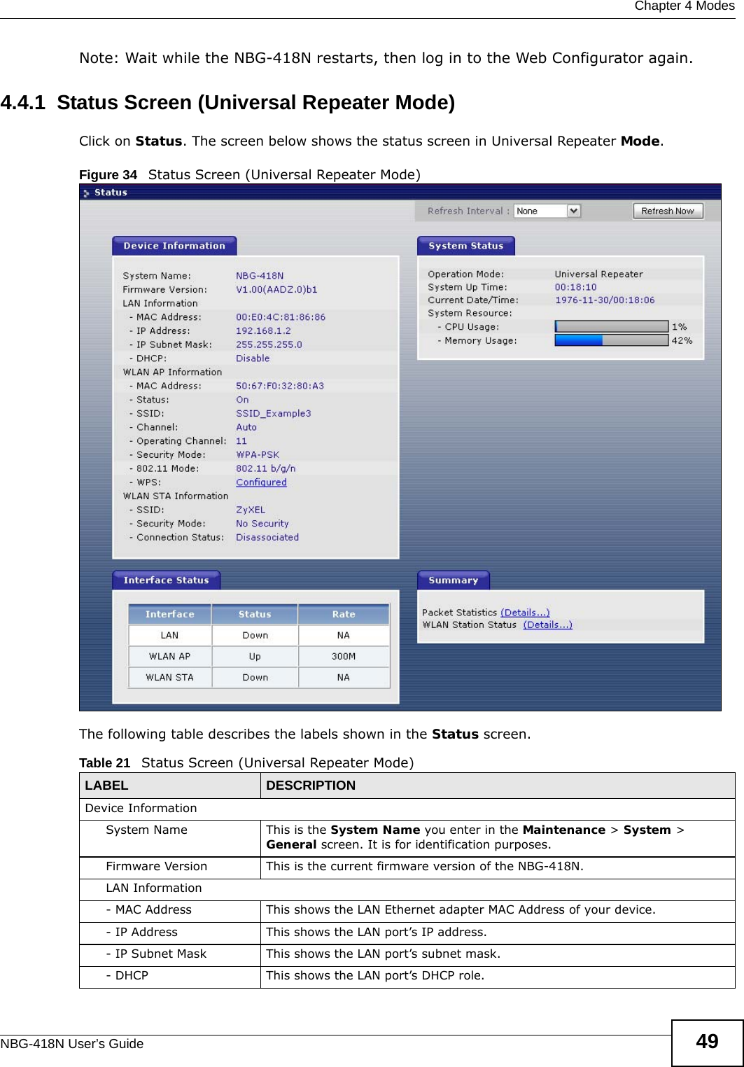
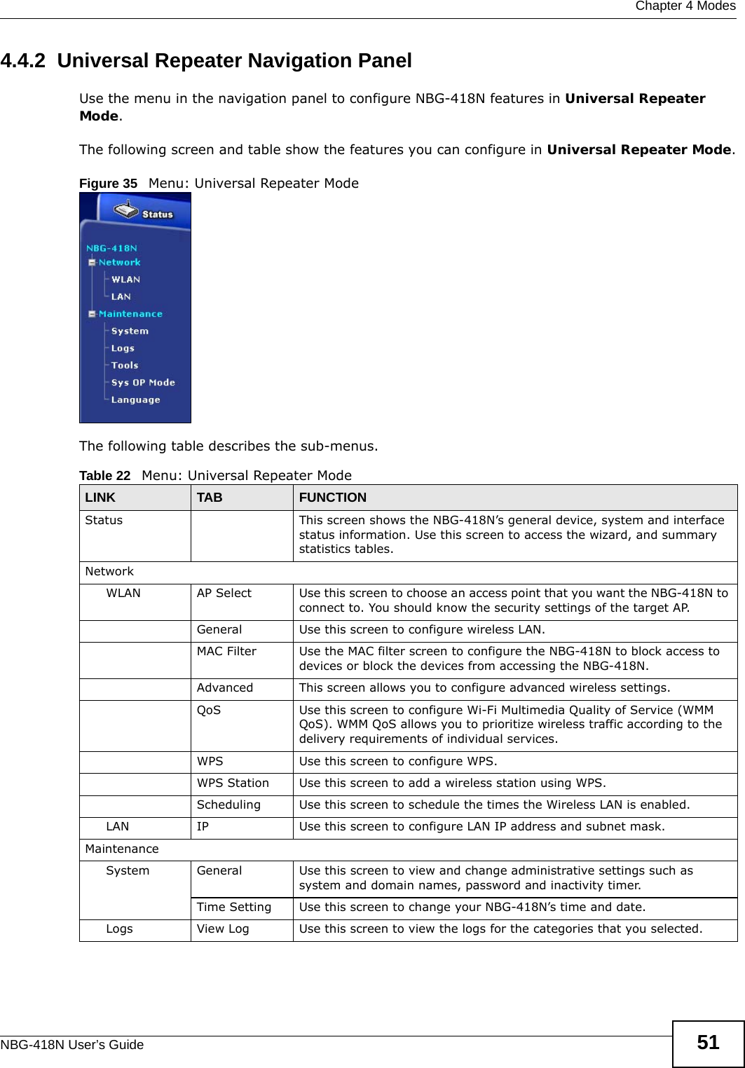
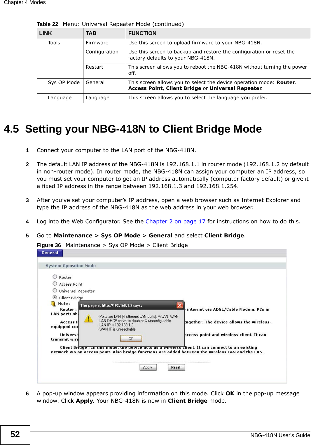
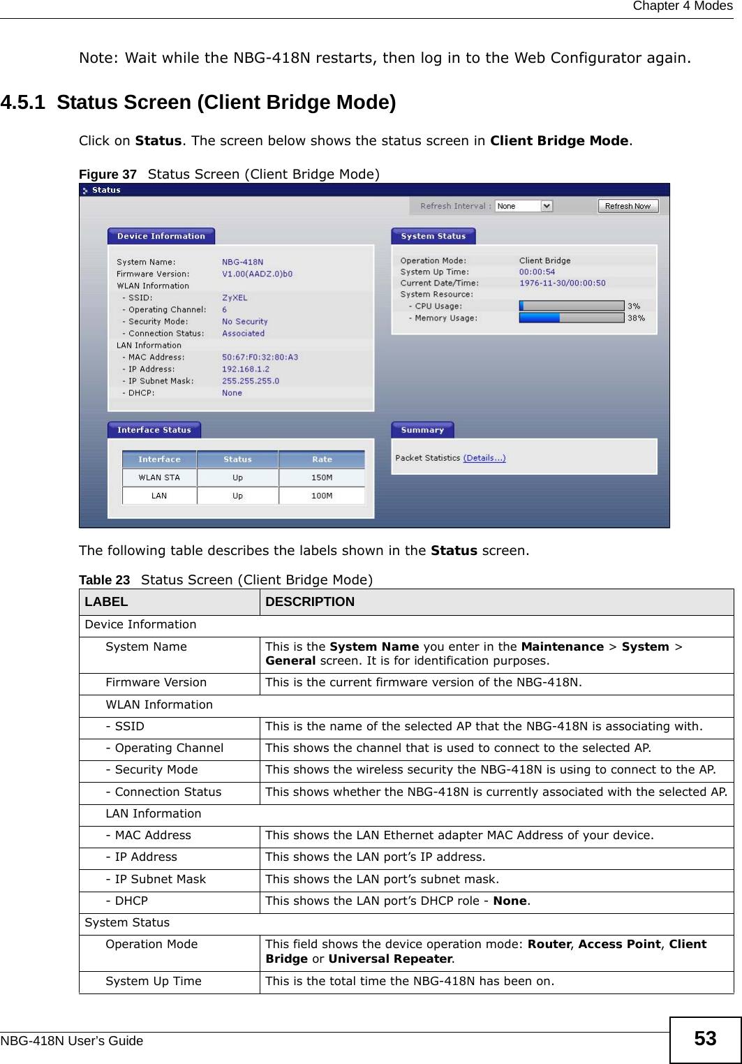
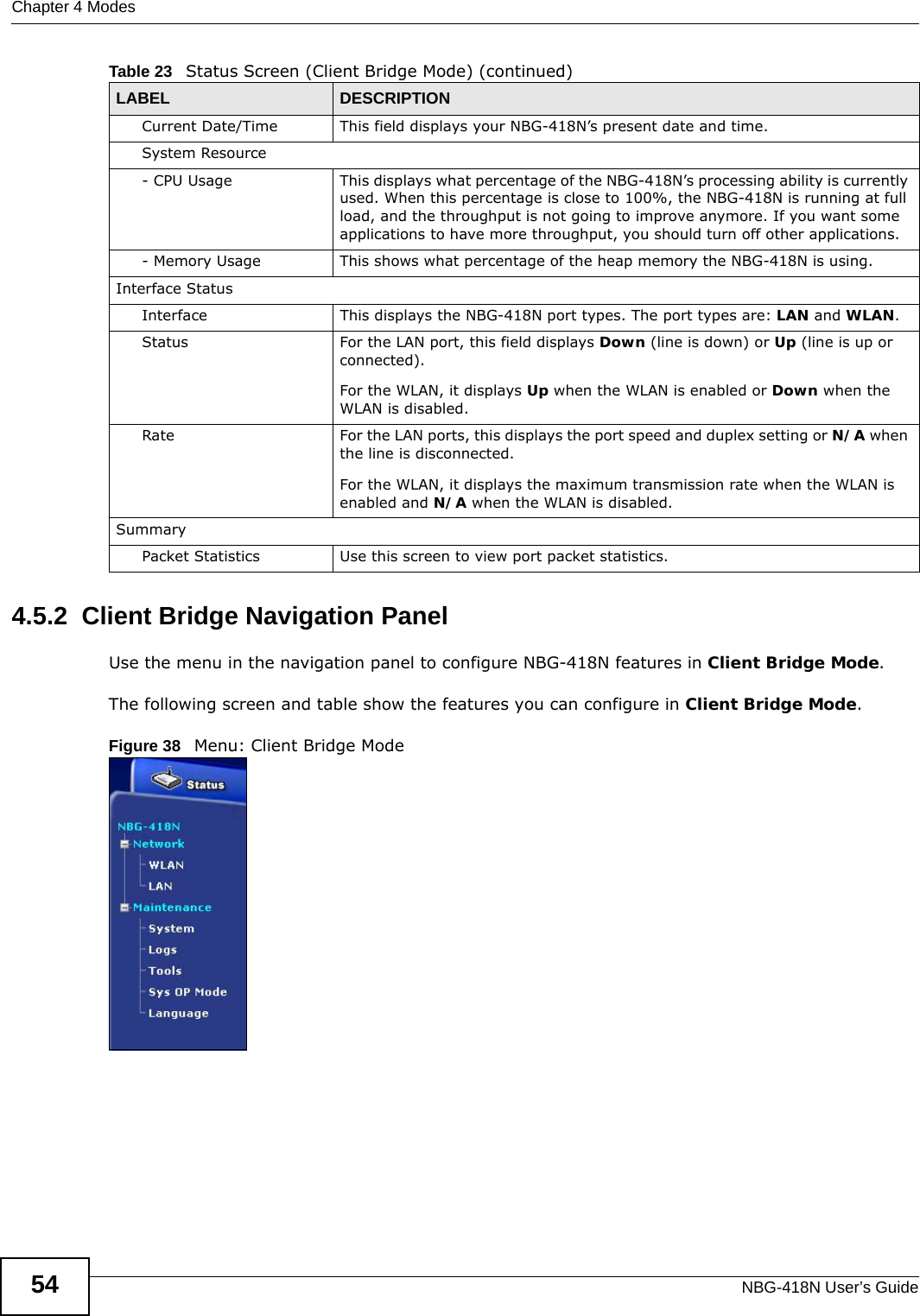
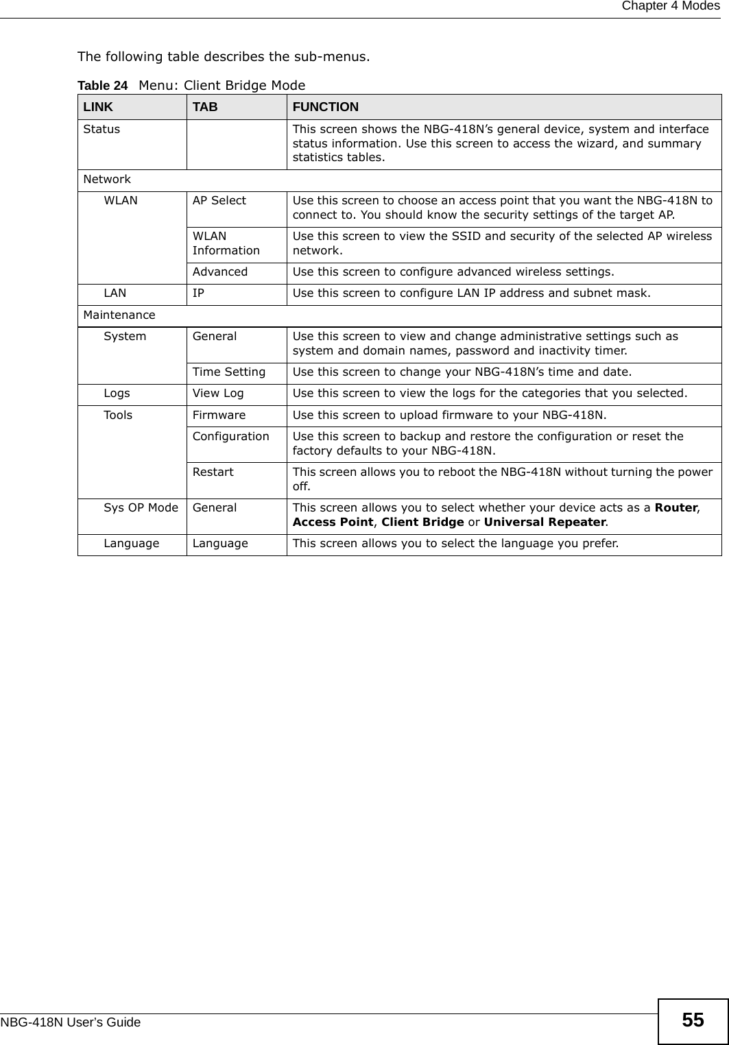
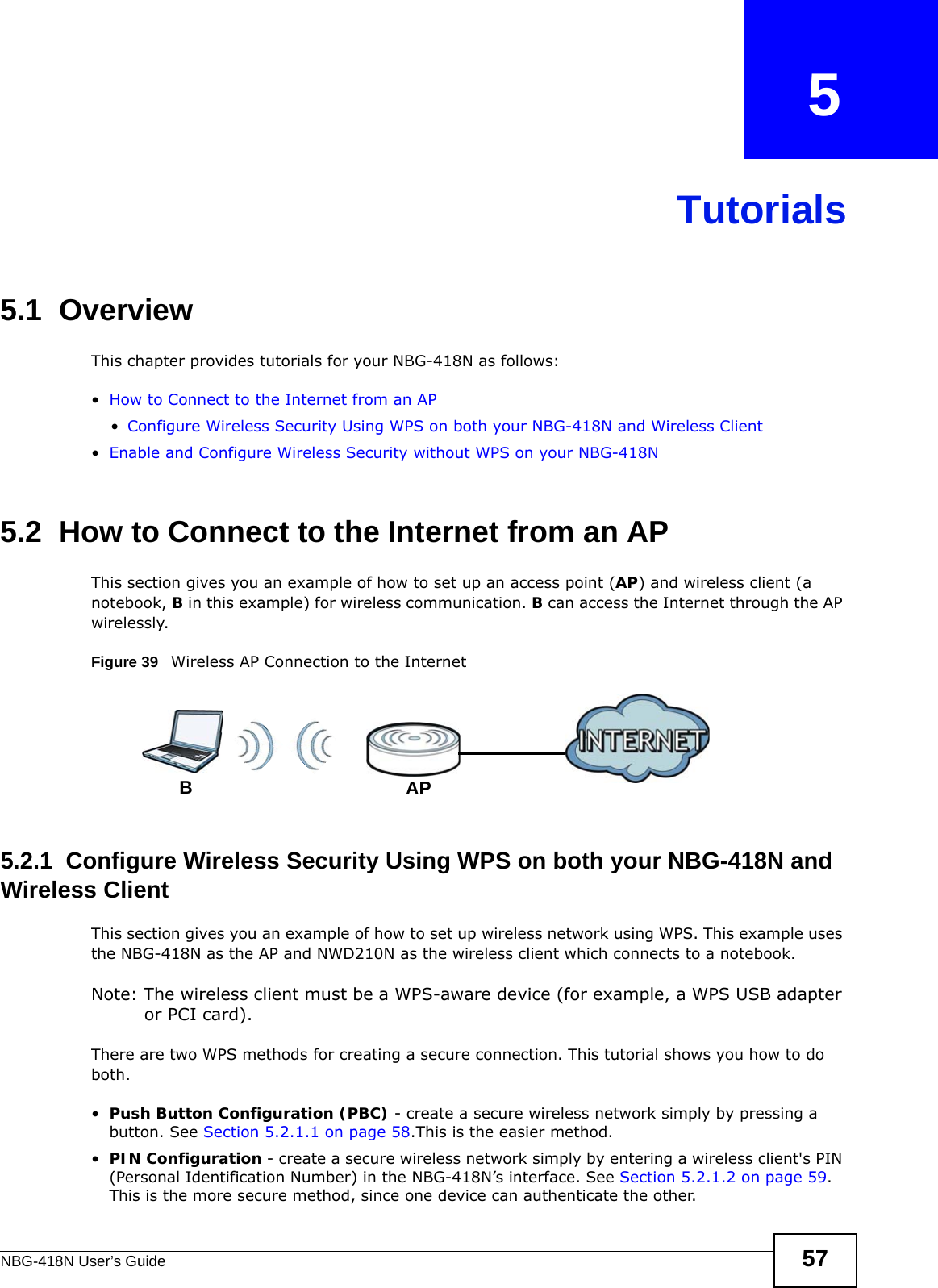
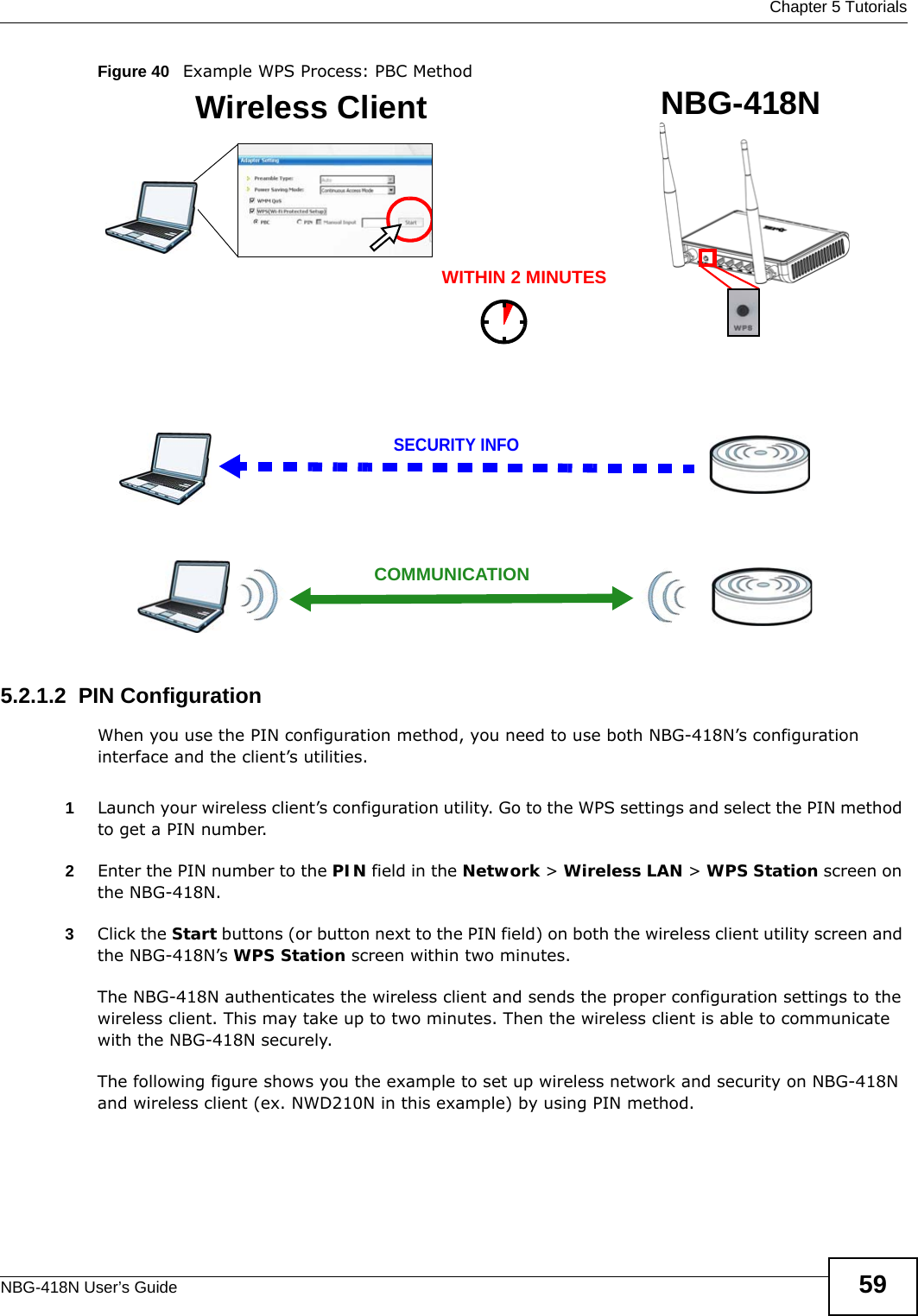
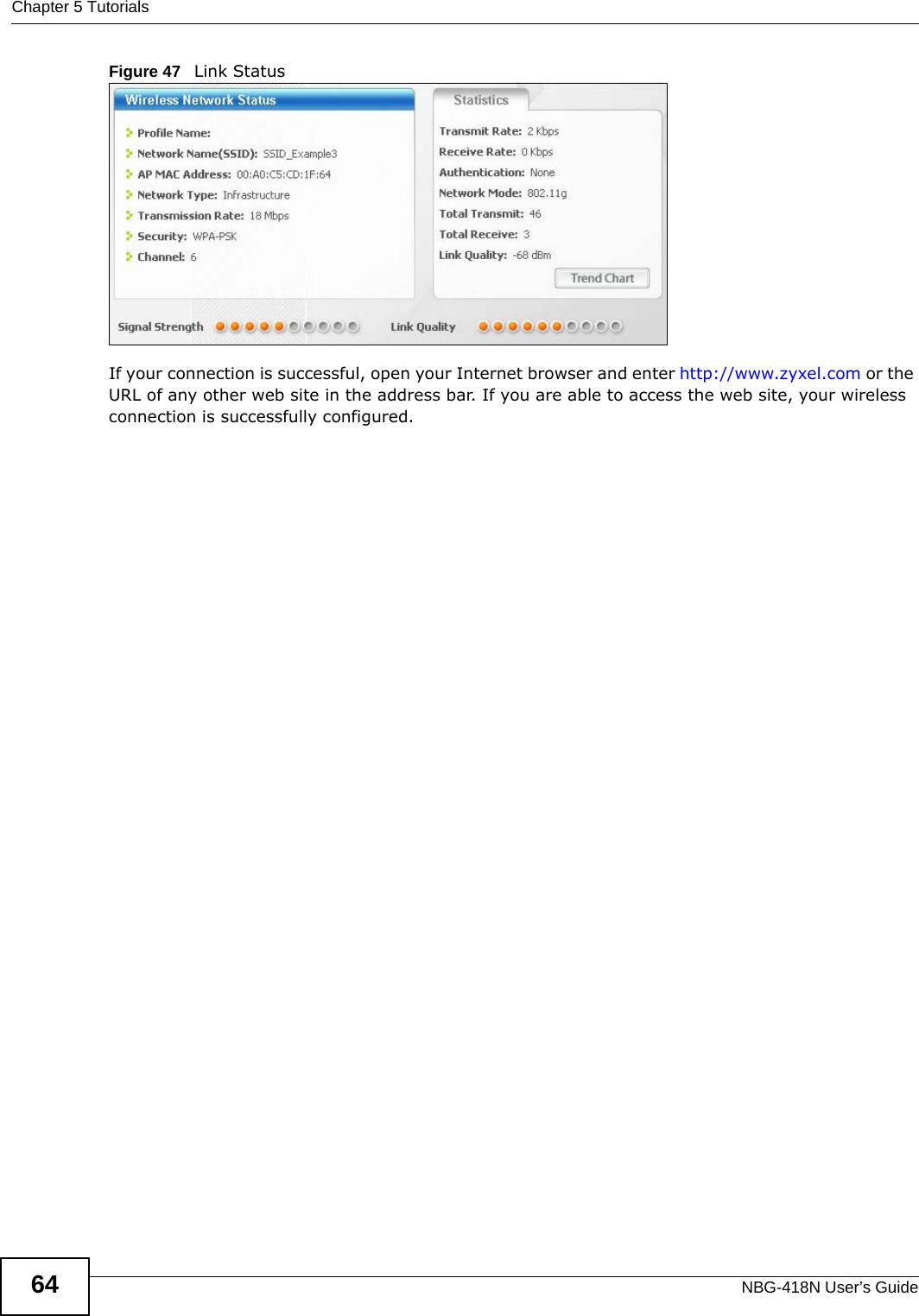
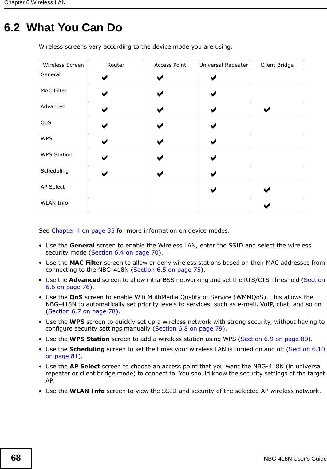
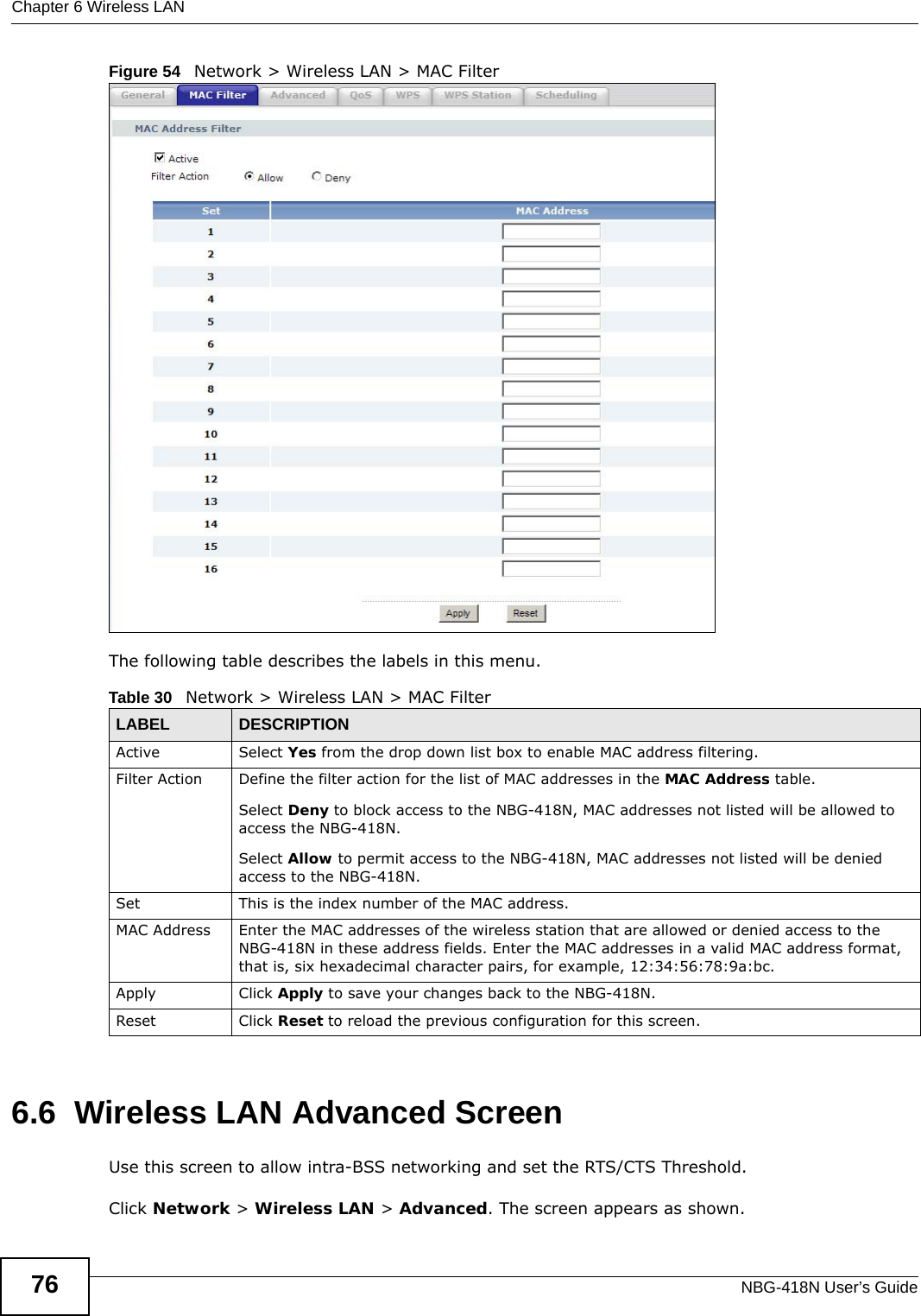
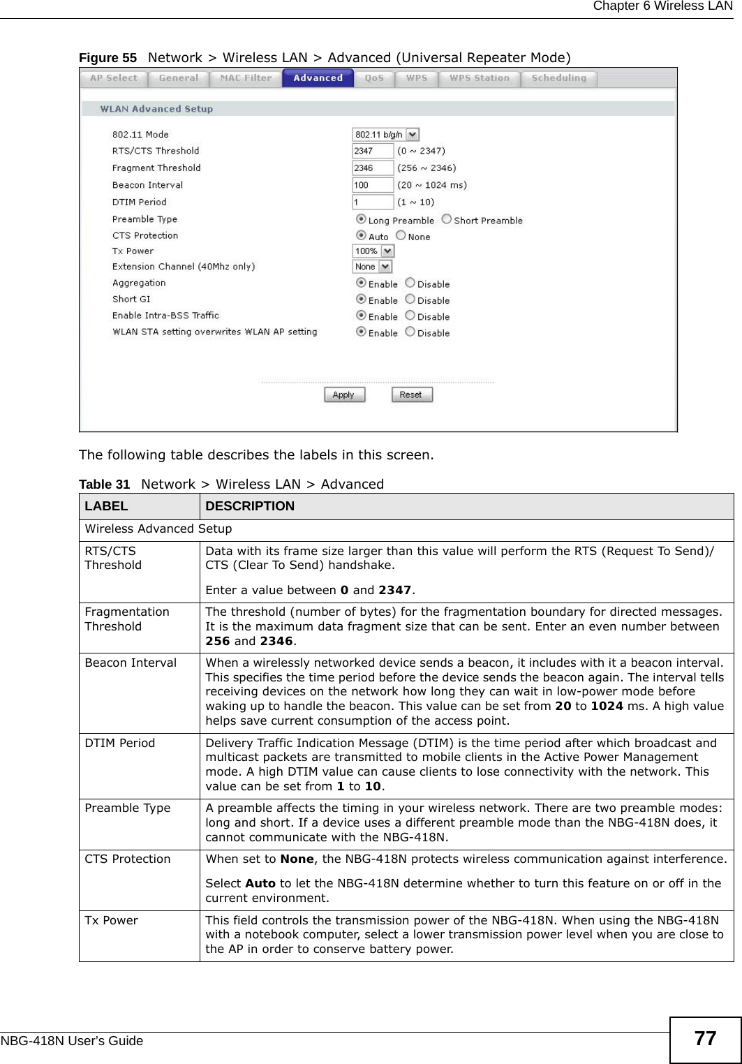
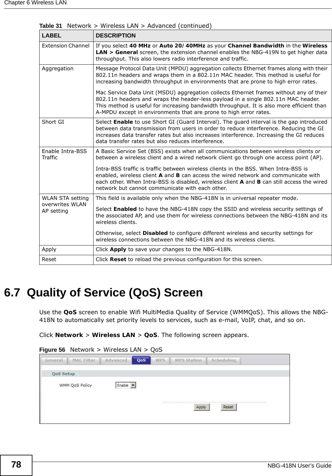
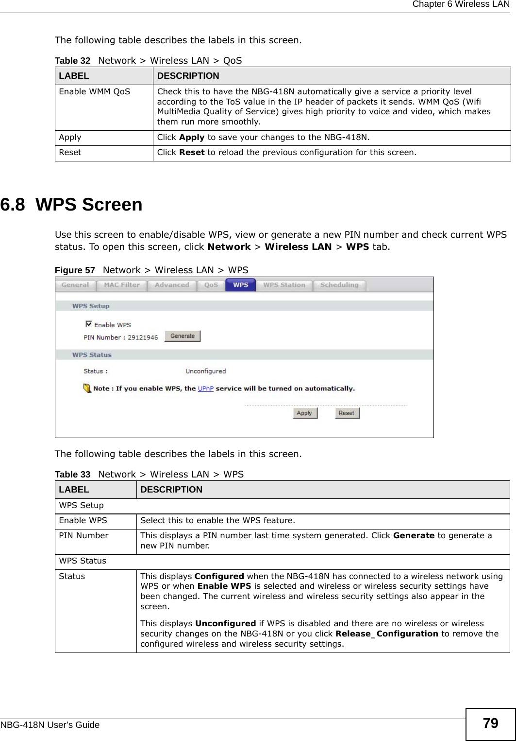
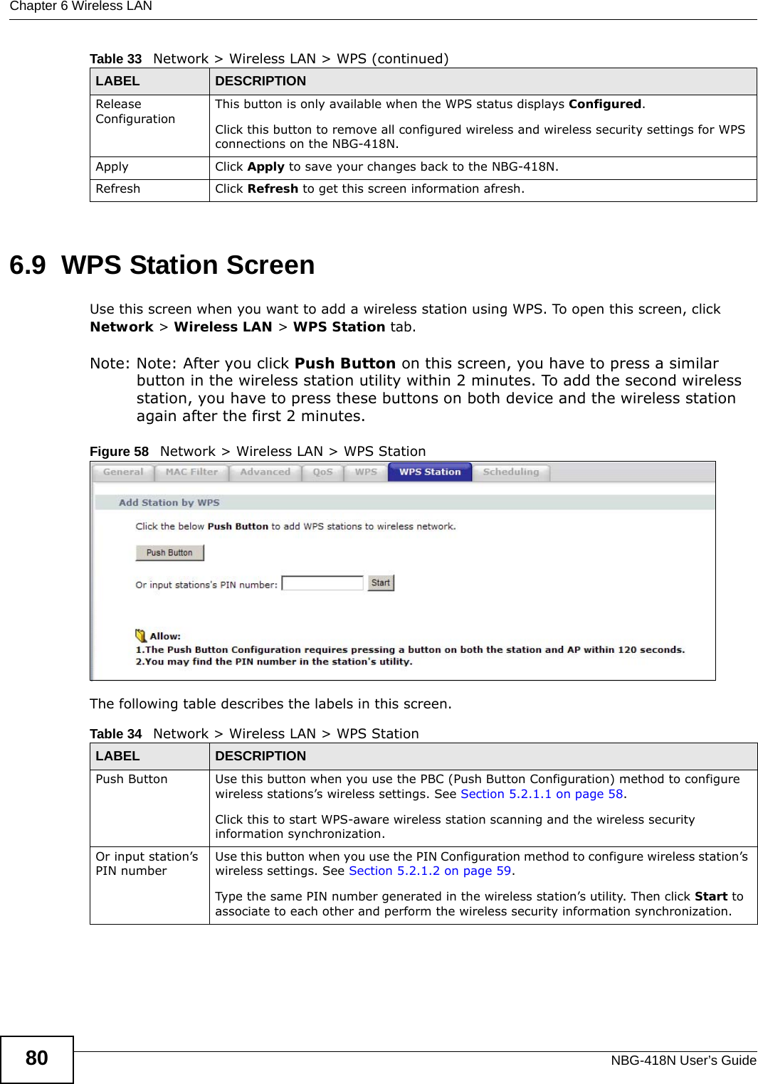
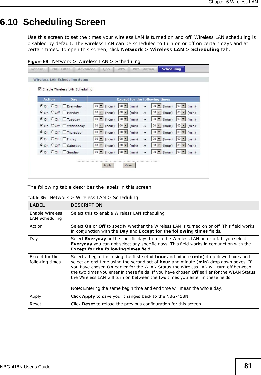
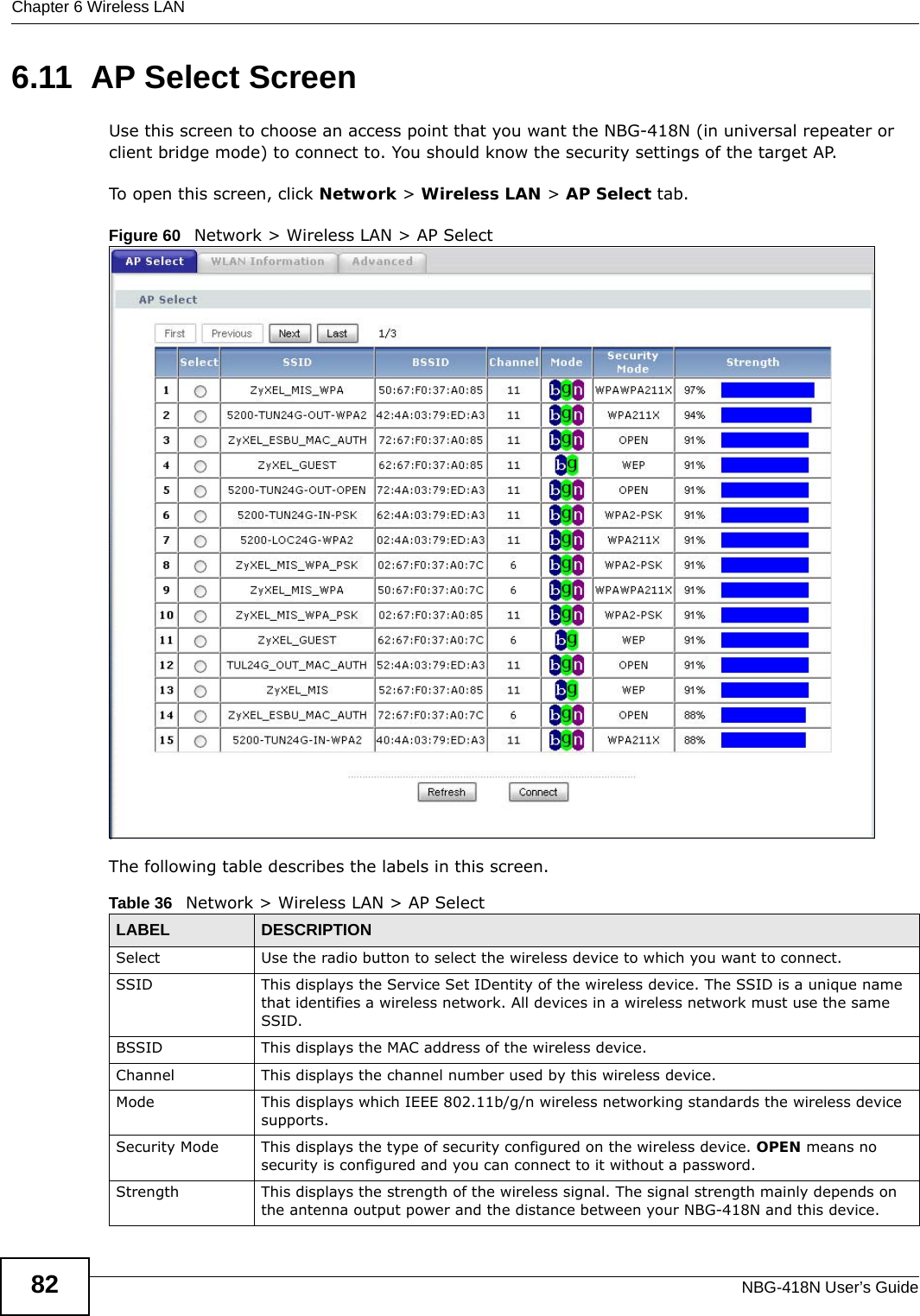
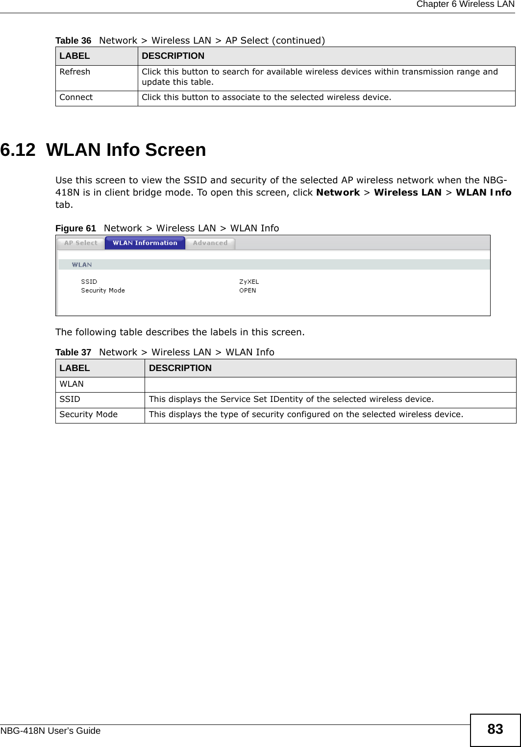
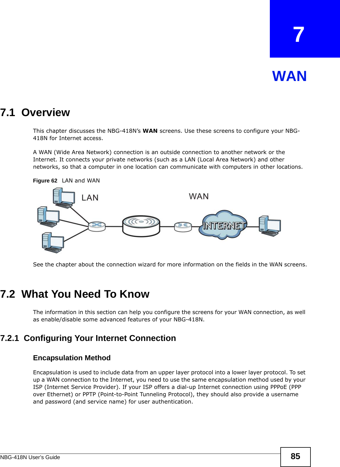
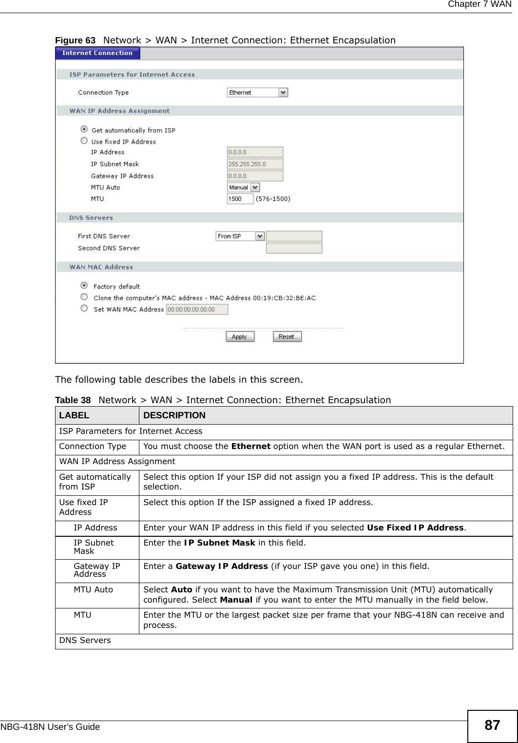
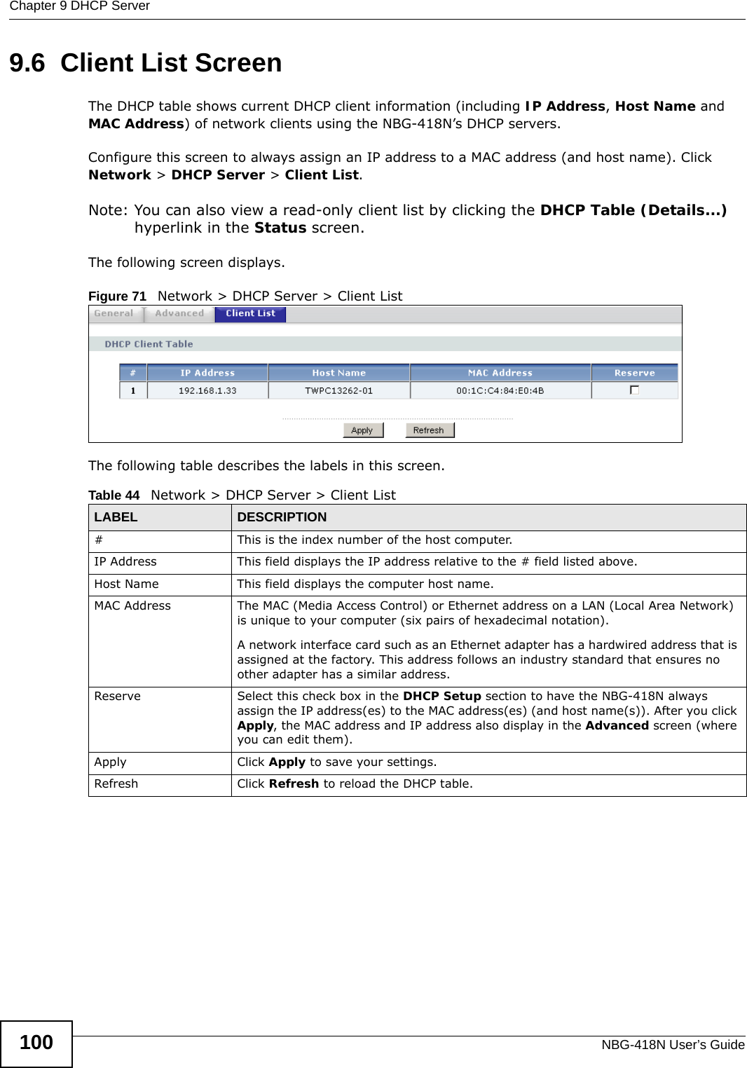
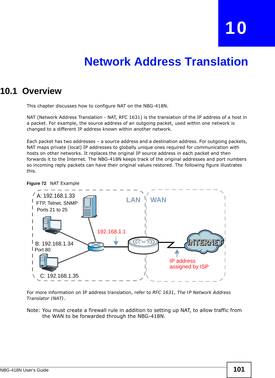
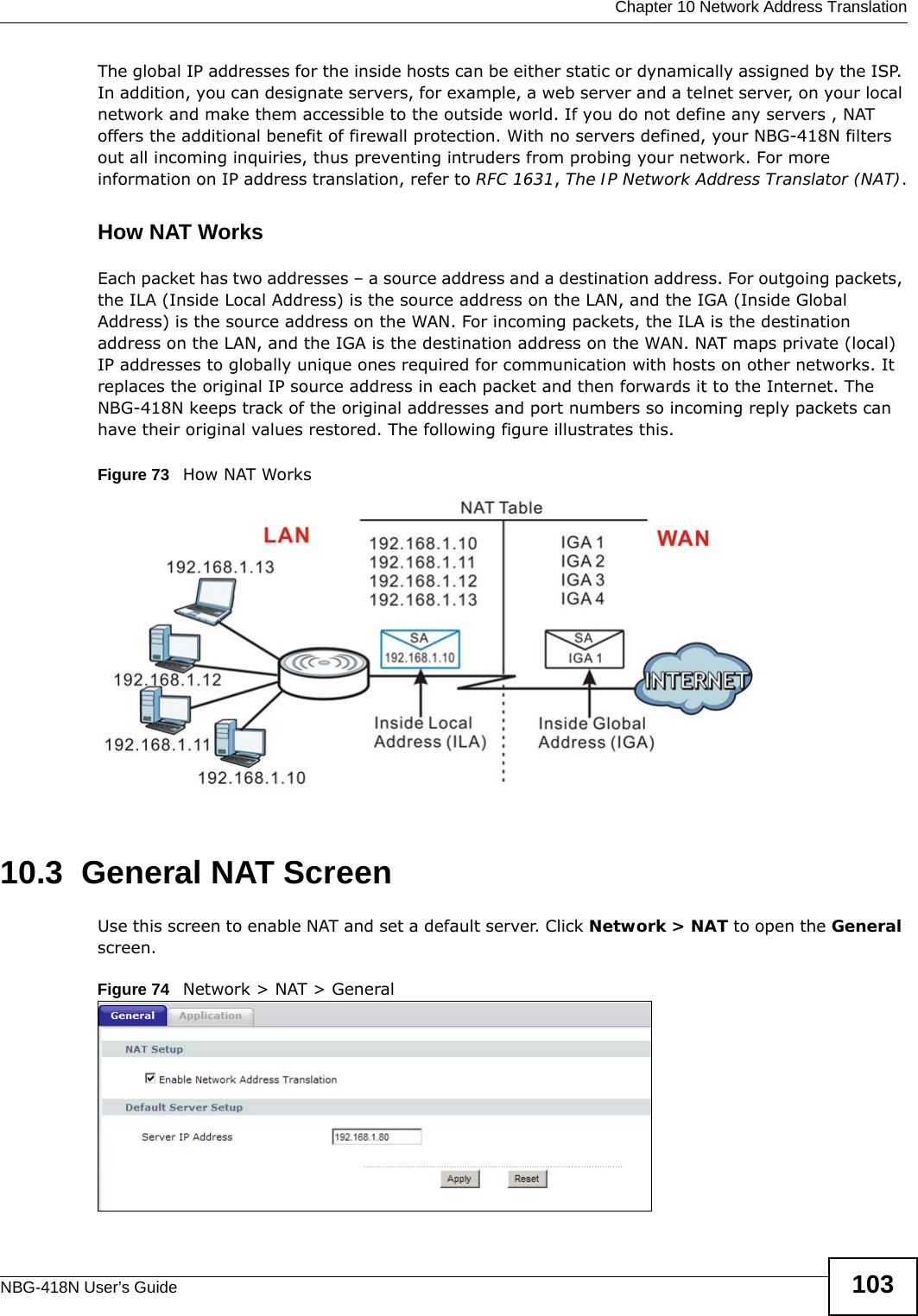
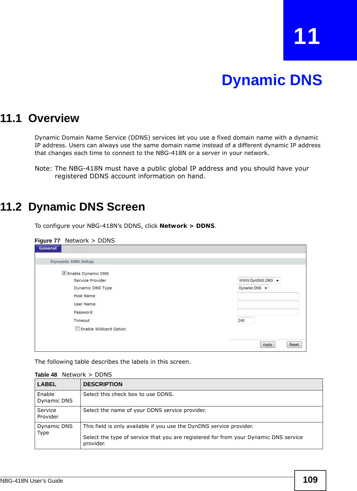
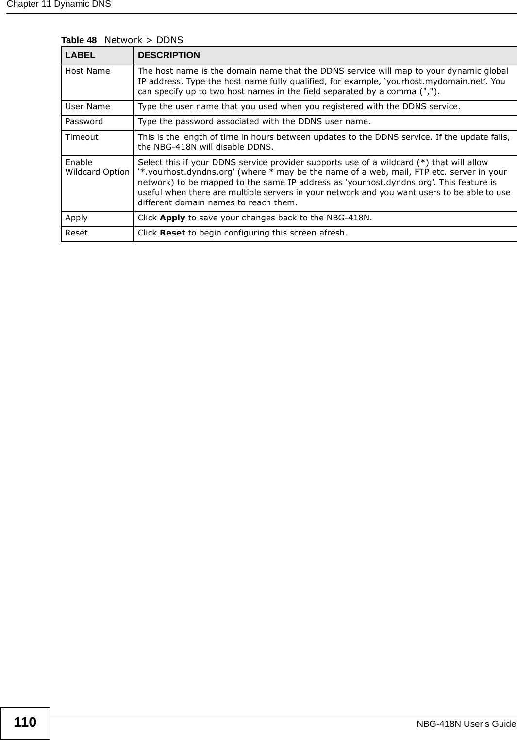
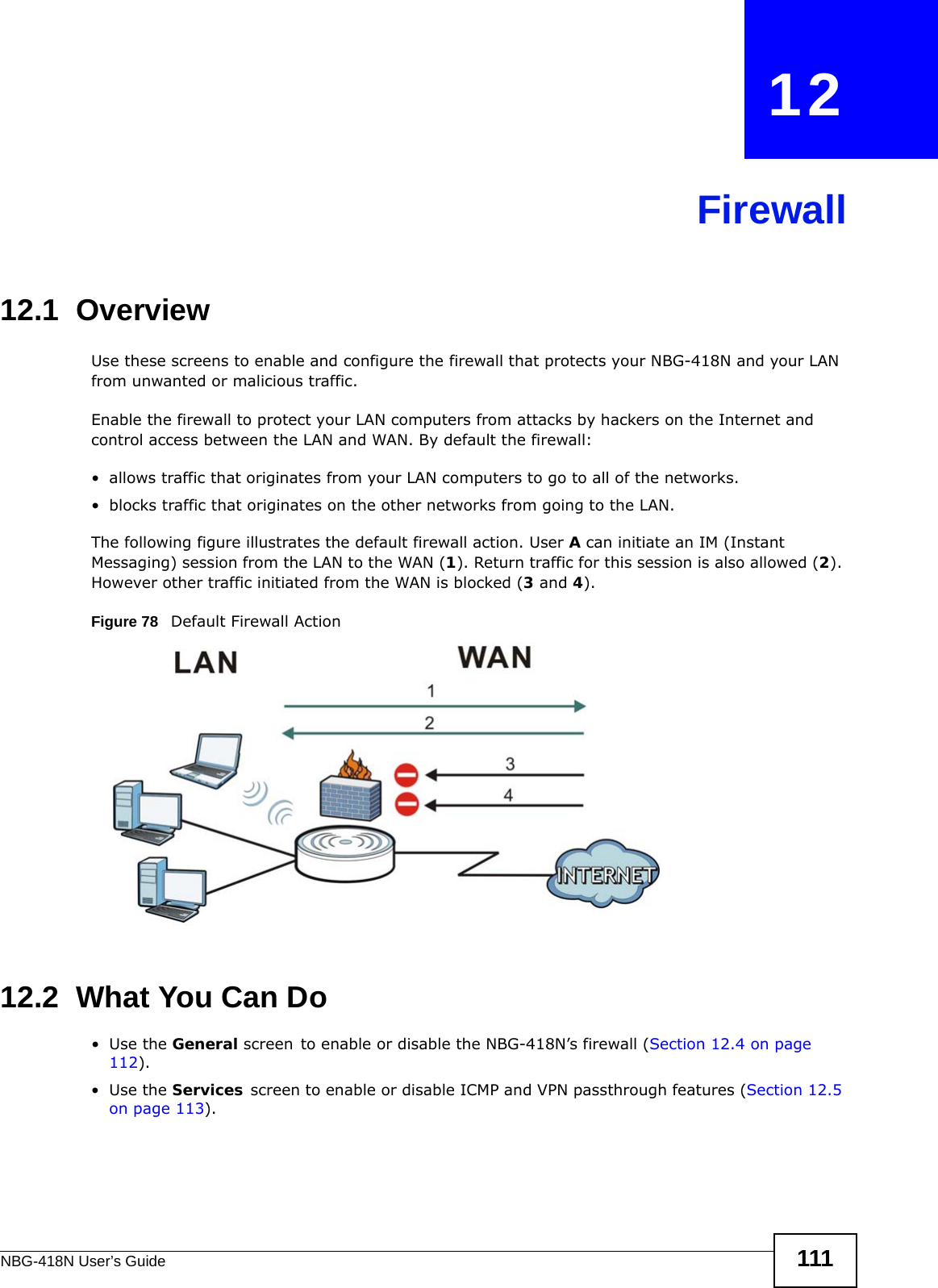
NBG-418N_User manual_Part1

www.zyxel.comwww.zyxel.comNBG-418NWireless N Home RouterIMPORTANT!READ CAREFULLY BEFORE USE.KEEP THIS GUIDE FOR FUTURE REFERENCE.IMPORTANT!Copyright © 2012 ZyXEL Communications CorporationVersion 1.00Edition 1, 4/2012Default Login DetailsLAN IP Address http://192.168.1.1User Name adminPassword 1234
NBG-418N User’s Guide2IMPORTANT!READ CAREFULLY BEFORE USE.KEEP THIS GUIDE FOR FUTURE REFERENCE.Graphics in this book may differ slightly from the product due to differences in operating systems, operating system versions, or if you installed updated firmware/software for your device. Every effort has been made to ensure that the information in this manual is accurate.Related Documentation•Quick Start Guide The Quick Start Guide shows how to connect the NBG-418N and configure it using the Web Configurator wizard.
 Contents OverviewNBG-418N User’s Guide 3Contents OverviewUser’s Guide .......................................................................................................................................11Introduction .............................................................................................................................................13The Web Configurator .............................................................................................................................17Connection Wizard ..................................................................................................................................21 Modes  ....................................................................................................................................................35Tutorials ..................................................................................................................................................57Technical Reference ..........................................................................................................................65Wireless LAN  ..........................................................................................................................................67WAN ........................................................................................................................................................85LAN .........................................................................................................................................................93DHCP Server  ..........................................................................................................................................97Network Address Translation  ................................................................................................................101Dynamic DNS ........................................................................................................................................109Firewall .................................................................................................................................................. 111Remote Management ............................................................................................................................ 115Universal Plug-and-Play (UPnP) ...........................................................................................................119System ..................................................................................................................................................125Logs ......................................................................................................................................................129Tools ......................................................................................................................................................131Sys OP Mode ........................................................................................................................................137Language ..............................................................................................................................................139Troubleshooting ....................................................................................................................................141
Contents OverviewNBG-418N User’s Guide4
  Table of ContentsNBG-418N User’s Guide 5Table of ContentsContents Overview  ..............................................................................................................................3Table of Contents .................................................................................................................................5Part I: User’s Guide ......................................................................................... 11Chapter   1Introduction.........................................................................................................................................131.1 Overview  ...........................................................................................................................................131.2 Securing the NBG-418N  ...................................................................................................................141.3 LEDs  .................................................................................................................................................151.4 The WPS Button  ...............................................................................................................................151.5 Wall Mounting  ...................................................................................................................................16Chapter   2The Web Configurator........................................................................................................................172.1 Overview  ...........................................................................................................................................172.2 Accessing the Web Configurator .......................................................................................................172.3 Resetting the NBG-418N  ..................................................................................................................192.3.1 Using the RESET Button .........................................................................................................19Chapter   3Connection Wizard .............................................................................................................................213.1 Wizard Setup .....................................................................................................................................213.2 Connection Wizard: STEP 1: System Information  ............................................................................223.2.1 System Name  ..........................................................................................................................223.2.2 Domain Name ..........................................................................................................................233.3 Connection Wizard: STEP 2: Wireless LAN ......................................................................................233.3.1 WPA-PSK or WPA2-PSK Security ...........................................................................................243.4 Connection Wizard: STEP 3: Internet Configuration .........................................................................253.4.1 Ethernet Connection ................................................................................................................263.4.2 PPPoE Connection ..................................................................................................................263.4.3 PPTP Connection ....................................................................................................................273.4.4 Your IP Address .......................................................................................................................283.4.5 WAN IP Address Assignment ..................................................................................................293.4.6 IP Address and Subnet Mask  ..................................................................................................303.4.7 DNS Server Address Assignment  ...........................................................................................303.4.8 WAN IP and DNS Server Address Assignment .......................................................................30
Table of ContentsNBG-418N User’s Guide63.4.9 WAN MAC Address  .................................................................................................................313.5 Connection Wizard Complete ...........................................................................................................32Chapter   4 Modes .................................................................................................................................................354.1 Overview  ...........................................................................................................................................354.2 Setting your NBG-418N to Router Mode ...........................................................................................364.2.1 Status Screen (Router Mode)  ..................................................................................................374.2.2 Router Mode Navigation Panel ................................................................................................424.3 Setting your NBG-418N to AP Mode .................................................................................................444.3.1 Status Screen (AP Mode)  ........................................................................................................454.3.2 AP Navigation Panel ................................................................................................................474.4 Setting your NBG-418N to Universal Repeater Mode .......................................................................484.4.1 Status Screen (Universal Repeater Mode)  ..............................................................................494.4.2 Universal Repeater Navigation Panel ......................................................................................514.5 Setting your NBG-418N to Client Bridge Mode .................................................................................524.5.1 Status Screen (Client Bridge Mode)  ........................................................................................534.5.2 Client Bridge Navigation Panel ................................................................................................54Chapter   5Tutorials...............................................................................................................................................575.1 Overview  ...........................................................................................................................................575.2 How to Connect to the Internet from an AP  ......................................................................................575.2.1 Configure Wireless Security Using WPS on both your NBG-418N and Wireless Client  .........575.3 Enable and Configure Wireless Security without WPS on your NBG-418N  .....................................61Part II: Technical Reference............................................................................ 65Chapter   6Wireless LAN.......................................................................................................................................676.1 Overview  ...........................................................................................................................................676.2 What You Can Do  .............................................................................................................................686.3 What You Should Know  ....................................................................................................................696.3.1 Wireless Security Overview .....................................................................................................696.4 General Wireless LAN Screen   .........................................................................................................706.4.1 No Security  ..............................................................................................................................726.4.2 WEP Encryption  ......................................................................................................................736.4.3 WPA-PSK/WPA2-PSK .............................................................................................................746.5 MAC Filter  .........................................................................................................................................756.6 Wireless LAN Advanced Screen .......................................................................................................766.7 Quality of Service (QoS) Screen .......................................................................................................78
  Table of ContentsNBG-418N User’s Guide 76.8 WPS Screen ......................................................................................................................................796.9 WPS Station Screen ..........................................................................................................................806.10 Scheduling Screen ..........................................................................................................................816.11 AP Select Screen  ............................................................................................................................826.12 WLAN Info Screen  ..........................................................................................................................83Chapter   7WAN .....................................................................................................................................................857.1 Overview  ...........................................................................................................................................857.2 What You Need To Know  ..................................................................................................................857.2.1 Configuring Your Internet Connection ......................................................................................857.3 Internet Connection ...........................................................................................................................867.3.1 Ethernet Encapsulation  ...........................................................................................................867.3.2 PPPoE Encapsulation .............................................................................................................887.3.3 PPTP Encapsulation ................................................................................................................90Chapter   8LAN ......................................................................................................................................................938.1 Overview  ...........................................................................................................................................938.2 What You Need To Know  ..................................................................................................................938.2.1 IP Pool Setup ...........................................................................................................................948.2.2 LAN TCP/IP  .............................................................................................................................948.3 LAN IP Screen  ..................................................................................................................................94Chapter   9DHCP Server .......................................................................................................................................979.1 Overview  ...........................................................................................................................................979.2 What You Can Do  .............................................................................................................................979.3 What You Need To Know  ..................................................................................................................979.4 General Screen .................................................................................................................................979.5 Advanced Screen    ...........................................................................................................................989.6 Client List Screen ............................................................................................................................100Chapter   10Network Address Translation..........................................................................................................10110.1 Overview     ....................................................................................................................................10110.2 What You Can Do  .........................................................................................................................10210.2.1 What You Need To Know .....................................................................................................10210.3 General NAT Screen .....................................................................................................................10310.4 NAT Application Screen    ..............................................................................................................10410.5 Technical Reference ......................................................................................................................10610.5.1 NAT Port Forwarding: Services and Port Numbers .............................................................10610.5.2 NAT Port Forwarding Example  ............................................................................................107
Table of ContentsNBG-418N User’s Guide8Chapter   11Dynamic DNS ....................................................................................................................................10911.1 Overview   ......................................................................................................................................10911.2 Dynamic DNS Screen    .................................................................................................................109Chapter   12Firewall .............................................................................................................................................. 11112.1 Overview    ..................................................................................................................................... 11112.2 What You Can Do  ......................................................................................................................... 11112.3 What You Need To Know  .............................................................................................................. 11212.3.1 About the NBG-418N Firewall  .............................................................................................11212.3.2 VPN Pass Through Features ...............................................................................................11212.4 General Firewall Screen    ............................................................................................................. 11212.5 Services Screen    .........................................................................................................................113Chapter   13Remote Management........................................................................................................................11513.1 Overview  .......................................................................................................................................11513.1.1 Remote Management Limitations ........................................................................................ 11613.1.2 Remote Management and NAT  ........................................................................................... 11613.1.3 System Timeout ................................................................................................................... 11613.2 WWW Screen    .............................................................................................................................116Chapter   14Universal Plug-and-Play (UPnP)......................................................................................................11914.1 Overview   ......................................................................................................................................11914.2 What You Need to Know  ............................................................................................................... 11914.3 Configuring UPnP  .........................................................................................................................12014.3.1 Using UPnP in Windows XP Example .................................................................................12014.3.2 Web Configurator Easy Access ...........................................................................................122Chapter   15System...............................................................................................................................................12515.1 Overview  .......................................................................................................................................12515.2 What You Can Do  .........................................................................................................................12515.3 System General Screen  ...............................................................................................................12515.4 Time Setting Screen ......................................................................................................................126Chapter   16Logs ...................................................................................................................................................12916.1 Overview  .......................................................................................................................................12916.2 What You Need to Know  ...............................................................................................................12916.3 View Log Screen ...........................................................................................................................129
  Table of ContentsNBG-418N User’s Guide 9Chapter   17Tools ..................................................................................................................................................13117.1 Overview  .......................................................................................................................................13117.2 What You Can Do  .........................................................................................................................13117.3 Firmware Upload Screen  ..............................................................................................................13117.4 Configuration Screen  ....................................................................................................................13317.4.1 Backup Configuration ..........................................................................................................13317.4.2 Restore Configuration ..........................................................................................................13317.4.3 Back to Factory Defaults  .....................................................................................................13417.5 Restart Screen  ..............................................................................................................................134Chapter   18Sys OP Mode.....................................................................................................................................13718.1 Overview  .......................................................................................................................................13718.2 General Screen .............................................................................................................................137Chapter   19Language...........................................................................................................................................13919.1 Language Screen ..........................................................................................................................139Chapter   20Troubleshooting................................................................................................................................14120.1 Power, Hardware Connections, and LEDs ....................................................................................14120.2 NBG-418N Access and Login  .......................................................................................................14220.3 Internet Access  .............................................................................................................................14320.4 Resetting the NBG-418N to Its Factory Defaults  ..........................................................................14420.5 Wireless Problems ........................................................................................................................145Appendix   A  IP Addresses and Subnetting.......................................................................................147Appendix   B  Pop-up Windows, JavaScripts and Java Permissions..................................................157Appendix   C  Setting Up Your Computer’s IP Address ......................................................................167Appendix   D  Wireless LANs..............................................................................................................195Appendix   E  Common Services........................................................................................................209Appendix   F  Legal Information..........................................................................................................213Index ..................................................................................................................................................219
Table of ContentsNBG-418N User’s Guide10
11PART IUser’s Guide
12
NBG-418N User’s Guide 13CHAPTER   1Introduction1.1  OverviewThe NBG-418N extends the range of your existing wired network without additional wiring, providing easy network access to mobile users. Your can create the following connections using the NBG-418N:•LAN. You can connect network devices via the Ethernet ports of the NBG-418N so that they can communicate with each other and access the Internet.•WLAN. Wireless clients can connect to the NBG-418N to access network resources.•WAN. Connect to a broadband modem/router for Internet access.Figure 1   NBG-418N NetworkYou can set up the NBG-418N with other IEEE 802.11b/g/n compatible devices in one of the following device modes:•Router• Access Point• Universal Repeater• Client BridgeWLANWANLAN1LAN2LAN3LAN4
Chapter 1 IntroductionNBG-418N User’s Guide14Use a (supported) web browser to manage the NBG-418N. Menus vary according to which mode you’re using.See Chapter 4 on page 35 for more information on these modes.1.2  Securing the NBG-418NDo the following things regularly to make the NBG-418N more secure and to manage the NBG-418N more effectively.• Change the password. Use a password that’s not easy to guess and that consists of different types of characters, such as numbers and letters.• Write down the password and put it in a safe place.• Back up the configuration (and make sure you know how to restore it). Restoring an earlier working configuration may be useful if the device becomes unstable or even crashes. If you forget your password, you will have to reset the NBG-418N to its factory default settings. If you backed up an earlier configuration file, you would not have to totally re-configure the NBG-418N. You could simply restore your last configuration.Router Mode Non-Router Mode
 Chapter 1 IntroductionNBG-418N User’s Guide 151.3  LEDsFigure 2   Front PanelThe following table describes the LEDs and the WPS button.1.4  The WPS ButtonYour NBG-418N supports WiFi Protected Setup (WPS), which is an easy way to set up a secure wireless network. WPS is an industry standard specification, defined by the WiFi Alliance.WPS allows you to quickly set up a wireless network with strong security, without having to configure security settings manually. Each WPS connection works between two devices. Both devices must support WPS (check each device’s documentation to make sure). Depending on the devices you have, you can either press a button (recommended) on the device itself, or in its configuration utility or enter a PIN (a unique Personal Identification Number that Table 1   Front Panel LEDs and WPS ButtonLED COLOR STATUS DESCRIPTIONPOWER Green On The NBG-418N is receiving power and functioning properly. Off The NBG-418N is not receiving power.LAN 1-4 Green On The NBG-418N has a successful 10/100MB LAN connection. Blinking The NBG-418N is sending/receiving data through the LAN.Off The LAN is not connected.WAN Green On The NBG-418N has a successful 10/100MB WAN connection.Blinking The NBG-418N is sending/receiving data through the WAN.Off The WAN connection is not ready, or has failed.WLAN  Green On The NBG-418N is ready, but is not sending/receiving data through the wireless LAN. Blinking The NBG-418N is sending/receiving data through the wireless LAN.The NBG-418N is negotiating a WPS connection with a wireless client.Off The wireless LAN is not ready or has failed.WPS Green On WPS status is configured. Blinking The NBG-418N is negotiating a WPS connection with a wireless client.Off The WPS status is not configured or disabled.
Chapter 1 IntroductionNBG-418N User’s Guide16allows one device to authenticate the other) in each of the two devices. When WPS is activated on a device, it has two minutes to find another device that also has WPS activated. Then, the two devices connect and set up a secure network by themselves.For more information on using WPS, see Section 5.2.1 on page 57.1.5  Wall MountingYou may need screw anchors if mounting on a concrete or brick wall.1Select a position free of obstructions on a wall strong enough to hold the weight of the device. 2Mark two holes on the wall at the appropriate distance apart for the screws.Be careful to avoid damaging pipes or cables located inside the wall when drilling holes for the screws.3If using screw anchors, drill two holes for the screw anchors into the wall. Push the anchors into the full depth of the holes, then insert the screws into the anchors. Do not insert the screws all the way in - leave a small gap of about 0.5 cm.If not using screw anchors, use a screwdriver to insert the screws into the wall. Do not insert the screws all the way in - leave a gap of about 0.5 cm.4Make sure the screws are fastened well enough to hold the weight of the NBG-418N with the connection cables. 5Align the holes on the back of the NBG-418N with the screws on the wall. Hang the NBG-418N on the screws.Figure 3   Wall Mounting ExampleTable 2   Wall Mounting InformationDistance between holes 12 cmM4 Screws TwoScrew anchors (optional) Two
NBG-418N User’s Guide 17CHAPTER   2The Web Configurator2.1  OverviewThis chapter describes how to access the NBG-418N Web Configurator and provides an overview of its screens.The Web Configurator is an HTML-based management interface that allows easy setup and management of the NBG-418N via Internet browser. Use Internet Explorer 6.0 and later versions, Mozilla Firefox 3 and later versions, or Safari 2.0 and later versions. The recommended screen resolution is 1024 by 768 pixels.In order to use the Web Configurator you need to allow:• Web browser pop-up windows from your device. Web pop-up blocking is enabled by default in Windows XP SP (Service Pack) 2.• JavaScript (enabled by default).• Java permissions (enabled by default).Refer to Chapter 20 Troubleshooting to see how to make sure these functions are allowed in Internet Explorer.2.2  Accessing the Web Configurator1Make sure your NBG-418N hardware is properly connected and prepare your computer or computer network to connect to the NBG-418N (refer to the Quick Start Guide).2Launch your web browser.3Type "http://192.168.1.1" as the website address in your web browser. This is the default LAN IP address in router mode, the default device mode (192.168.1.2 is the default IP address in non-router mode).Your computer must be in the same subnet in order to access this website address. In router mode, the NBG-418N can assign your computer an IP address, so you must set your computer to get an IP address automatically (computer factory default) or give it a fixed IP address in the range between 192.168.1.3 and 192.168.1.254 (see the appendices).4Type admin (default) as the user name and 1234 (default) as the password and click OK.
Chapter 2 The Web ConfiguratorNBG-418N User’s Guide18Figure 4   Login ScreenNote: The management session automatically times out when the time period set in the Administrator Inactivity Timer field expires (default five minutes). Simply log back into the NBG-418N if this happens.5Select the setup type you want to use.• Click Go to Wizard Setup to use the Configuration Wizard for basic Internet and Wireless setup.• Click Go to Advanced Setup to view and configure all the NBG-418N’s settings.• Select a language to go to the basic Web Configurator in that language. To change to the advanced configurator see Chapter 19 on page 139.Figure 5    Selecting the setup mode
 Chapter 2 The Web ConfiguratorNBG-418N User’s Guide 192.3  Resetting the NBG-418NIf you forget your password or IP address, or you cannot access the Web Configurator, you will need to use the RESET button at the back of the NBG-418N to reload the factory-default configuration file. This means that you will lose all configurations that you had previously saved, the username will be reset to admin and password will be reset to 1234. The IP address will be reset to “192.168.1.1”.2.3.1  Using the RESET Button1Make sure the power LED is on.2Press the RESET button for longer than 1 second to restart/reboot the NBG-418N.3Press the RESET button for longer than five seconds to set the NBG-418N back to its factory-default configurations.
Chapter 2 The Web ConfiguratorNBG-418N User’s Guide20
NBG-418N User’s Guide 21CHAPTER   3Connection Wizard3.1  Wizard SetupThis chapter provides information on the wizard setup screens in the Web Configurator.The Web Configurator’s wizard setup helps you configure your device to access the Internet. Refer to your ISP (Internet Service Provider) checklist in the Quick Start Guide to know what to enter in each field. Leave a field blank if you don’t have that information.1After you access the NBG-418N Web Configurator, click Go to Wizard setup.You can click Go to Advanced setup to skip this wizard setup and configure basic or advanced features accordingly.Figure 6   Select Wizard or Advanced Mode2Choose a language by clicking on the language’s button. The screen will update. Click the Next button to proceed to the next screen.
Chapter 3 Connection WizardNBG-418N User’s Guide22Figure 7   Select a Language3Read the on-screen information and click Next.Figure 8   Welcome to the Connection Wizard3.2  Connection Wizard: STEP 1: System InformationSystem Information contains administrative and system-related information.3.2.1  System NameSystem Name is for identification purposes. However, because some ISPs check this name you should enter your computer's "Computer Name". • In Windows 95/98 click Start > Settings > Control Panel > Network. Click the Identification tab, note the entry for the Computer Name field and enter it as the System Name.• In Windows 2000, click Start > Settings and Control Panel and then double-click System. Click the Network Identification tab and then the Properties button. Note the entry for the Computer name field and enter it as the System Name.• In Windows XP, click Start > My Computer > View system information and then click the Computer Name tab. Note the entry in the Full computer name field and enter it as the NBG-418N System Name.
 Chapter 3 Connection WizardNBG-418N User’s Guide 233.2.2  Domain NameThe Domain Name entry is what is propagated to the DHCP clients on the LAN. If you leave this blank, the domain name obtained by DHCP from the ISP is used. While you must enter the host name (System Name) on each individual computer, the domain name can be assigned from the NBG-418N via DHCP.Click Next to configure the NBG-418N for Internet access.Figure 9   Wizard Step 1: System InformationThe following table describes the labels in this screen.3.3  Connection Wizard: STEP 2: Wireless LANSet up your wireless LAN using the following screen.Table 3   Wizard Step 1: System InformationLABEL DESCRIPTIONSystem Name System Name is a unique name to identify the NBG-418N in an Ethernet network. Enter a descriptive name. This name can be up to 30 alphanumeric characters long. Spaces are not allowed, but dashes "-" and underscores "_" are accepted. Domain Name Type the domain name (if you know it) here. If you leave this field blank, the ISP may assign a domain name via DHCP. The domain name entered by you is given priority over the ISP assigned domain name.Back Click Back to display the previous screen.Next Click Next to proceed to the next screen. Exit Click Exit to close the wizard screen without saving.
Chapter 3 Connection WizardNBG-418N User’s Guide24Figure 10   Wizard Step 2: Wireless LANThe following table describes the labels in this screen.Note: The wireless stations and NBG-418N must use the same SSID, channel ID, WPA-PSK (if WPA-PSK is enabled) or WPA2-PSK (if WPA2-PSK is enabled) for wireless communication.3.3.1  WPA-PSK or WPA2-PSK SecurityChoose WPA-PSK or WPA2-PSK security in the Wireless LAN setup screen to set up a Pre-Shared Key.Table 4   Wizard Step 2: Wireless LANLABEL DESCRIPTIONName (SSID) Enter a descriptive name (up to 32 printable 7-bit ASCII characters) for the wireless LAN. If you change this field on the NBG-418N, make sure all wireless stations use the same SSID in order to access the network. Security Select a Security level from the drop-down list box.Choose None to have no wireless LAN security configured. If you do not enable any wireless security on your NBG-418N, your network is accessible to any wireless networking device that is within range. If you choose this option, skip directly to Section 3.4 on page 25.Choose WPA-PSK or WPA2-PSK security to configure a Pre-Shared Key. Choose this option only if your wireless clients support WPA-PSK or WPA2-PSK respectively. If you choose this option, skip directly to Section 3.3.1 on page 24. Channel SelectionThe range of radio frequencies used by IEEE 802.11b/g/n wireless devices is called a channel. Set the operating frequency/channel depending on your particular region. Select a channel from the drop-down list box. The options vary depending on the frequency band and the country you are in.This option is only available if Auto Channel Selection is disabled.Auto Channel Selection Select this option for the NBG-418N to automatically choose the channel with the least interference. Deselect this option if you wish to manually select the channel using the Channel Selection field.Back Click Back to display the previous screen.Next Click Next to proceed to the next screen. Exit Click Exit to close the wizard screen without saving.
 Chapter 3 Connection WizardNBG-418N User’s Guide 25Figure 11   Wizard Step 2: WPA-PSK or WPA2-PSK SecurityThe following table describes the labels in this screen. 3.4  Connection Wizard: STEP 3: Internet ConfigurationThe NBG-418N offers three Internet connection types. They are Ethernet, PPP over Ethernet or PPTP. The wizard attempts to detect which WAN connection type you are using. If the wizard does not detect a connection type, you must select one from the drop-down list box. Check with your ISP to make sure you use the correct type.This wizard screen varies according to the connection type that you select.Figure 12   Wizard Step 3: ISP Parameters.Table 5   Wizard Step 2: WPA-PSK or WPA2-PSK SecurityLABEL DESCRIPTIONPre-Shared Key Type from 8 to 63 case-sensitive ASCII characters or 64 HEX characters. You can set up the most secure wireless connection by configuring WPA in the wireless LAN screens. You need to configure an authentication server to do this.Back Click Back to display the previous screen.Next Click Next to proceed to the next screen. Exit Click Exit to close the wizard screen without saving.
Chapter 3 Connection WizardNBG-418N User’s Guide26The following table describes the labels in this screen,3.4.1  Ethernet ConnectionChoose Ethernet when the WAN port is used as a regular Ethernet. Continue to Section 3.4.4 on page 28.Figure 13   Wizard Step 3: Ethernet Connection3.4.2  PPPoE ConnectionPoint-to-Point Protocol over Ethernet (PPPoE) functions as a dial-up connection. PPPoE is an IETF (Internet Engineering Task Force) standard specifying how a host personal computer interacts with a broadband modem (for example DSL, cable, wireless, etc.) to achieve access to high-speed data networks.For the service provider, PPPoE offers an access and authentication method that works with existing access control systems (for instance, RADIUS). One of the benefits of PPPoE is the ability to let end users access one of multiple network services, a function known as dynamic service selection. This enables the service provider to easily create and offer new IP services for specific users.Operationally, PPPoE saves significant effort for both the subscriber and the ISP/carrier, as it requires no specific configuration of the broadband modem at the subscriber’s site.By implementing PPPoE directly on the NBG-418N (rather than individual computers), the computers on the LAN do not need PPPoE software installed, since the NBG-418N does that part of the task. Furthermore, with NAT, all of the LAN's computers will have Internet access.Table 6   Wizard Step 3: ISP ParametersCONNECTION TYPE DESCRIPTIONEthernet Select the Ethernet option when the WAN port is used as a regular Ethernet. PPPoE Select the PPP over Ethernet option for a dial-up connection. If your ISP gave you an IP address and/or subnet mask, then select PPTP.PPTP Select the PPTP option for a dial-up connection.
 Chapter 3 Connection WizardNBG-418N User’s Guide 27Figure 14   Wizard Step 3: PPPoE ConnectionThe following table describes the labels in this screen.3.4.3  PPTP ConnectionPoint-to-Point Tunneling Protocol (PPTP) is a network protocol that enables transfers of data from a remote client to a private server, creating a Virtual Private Network (VPN) using TCP/IP-based networks.PPTP supports on-demand, multi-protocol, and virtual private networking over public networks, such as the Internet.Refer to the appendix for more information on PPTP.Note: The NBG-418N supports one PPTP server connection at any given time.Table 7   Wizard Step 3: PPPoE ConnectionLABEL DESCRIPTIONISP Parameter for Internet AccessConnection Type Select the PPP over Ethernet option for a dial-up connection.Service Name  Type the name of your service provider.User Name Type the user name given to you by your ISP. Password  Type the password associated with the user name above.Back Click Back to return to the previous screen. Next Click Next to continue. Exit Click Exit to close the wizard screen without saving.
Chapter 3 Connection WizardNBG-418N User’s Guide28Figure 15   Wizard Step 3: PPTP ConnectionThe following table describes the fields in this screen3.4.4  Your IP AddressThe following wizard screen allows you to assign a fixed IP address or give the NBG-418N an automatically assigned IP address depending on your ISP.Table 8   Wizard Step 3: PPTP ConnectionLABEL DESCRIPTIONISP Parameters for Internet AccessConnection Type Select PPTP from the drop-down list box. To configure a PPTP client, you must configure the User Name and Password fields for a PPP connection and the PPTP parameters for a PPTP connection.User Name Type the user name given to you by your ISP. Password Type the password associated with the User Name above.PPTP ConfigurationServer IP Address Type the IP address of the PPTP server.Get automatically from ISPSelect this radio button if your ISP did not assign you a fixed IP address.Use fixed IP address Select this radio button, provided by your ISP to give the NBG-418N a fixed, unique IP address.My IP Address Type the (static) IP address assigned to you by your ISP.My IP Subnet Mask Type the subnet mask assigned to you by your ISP (if given).My IP Gateway  Type the gateway IP address assigned to you by your ISP (if given).Back Click Back to return to the previous screen.Next Click Next to continue. Exit Click Exit to close the wizard screen without saving.
 Chapter 3 Connection WizardNBG-418N User’s Guide 29Figure 16   Wizard Step 3: Your IP AddressThe following table describes the labels in this screen3.4.5  WAN IP Address AssignmentEvery computer on the Internet must have a unique IP address. If your networks are isolated from the Internet, for instance, only between your two branch offices, you can assign any IP addresses to the hosts without problems. However, the Internet Assigned Numbers Authority (IANA) has reserved the following three blocks of IP addresses specifically for private networks.You can obtain your IP address from the IANA, from an ISP or have it assigned by a private network. If you belong to a small organization and your Internet access is through an ISP, the ISP can provide you with the Internet addresses for your local networks. On the other hand, if you are part of a much larger organization, you should consult your network administrator for the appropriate IP addresses.Note: Regardless of your particular situation, do not create an arbitrary IP address; always follow the guidelines above. For more information on address assignment, please refer to RFC 1597, Address Allocation for Private Internets and RFC 1466, Guidelines for Management of IP Address Space.Table 9   Wizard Step 3: Your IP AddressLABEL DESCRIPTIONGet automatically from your ISP Select this option If your ISP did not assign you a fixed IP address. This is the default selection. If you choose this option, skip directly to Section 3.4.9 on page 31.Use fixed IP address provided by your ISPSelect this option if you were given IP address and/or DNS server settings by the ISP. The fixed IP address should be in the same subnet as your broadband modem or router. Back Click Back to return to the previous screen.Next Click Next to continue. Exit Click Exit to close the wizard screen without saving.Table 10   Private IP Address Ranges10.0.0.0 -10.255.255.255172.16.0.0 -172.31.255.255192.168.0.0 -192.168.255.255
Chapter 3 Connection WizardNBG-418N User’s Guide303.4.6  IP Address and Subnet MaskSimilar to the way houses on a street share a common street name, so too do computers on a LAN share one common network number.Where you obtain your network number depends on your particular situation. If the ISP or your network administrator assigns you a block of registered IP addresses, follow their instructions in selecting the IP addresses and the subnet mask.If the ISP did not explicitly give you an IP network number, then most likely you have a single user account and the ISP will assign you a dynamic IP address when the connection is established. The Internet Assigned Number Authority (IANA) reserved this block of addresses specifically for private use; please do not use any other number unless you are told otherwise. Let's say you select 192.168.1.0 as the network number; which covers 254 individual addresses, from 192.168.1.1 to 192.168.1.254 (zero and 255 are reserved). In other words, the first three numbers specify the network number while the last number identifies an individual computer on that network.Once you have decided on the network number, pick an IP address that is easy to remember, for instance, 192.168.1.1, for your NBG-418N, but make sure that no other device on your network is using that IP address.The subnet mask specifies the network number portion of an IP address. Your NBG-418N will compute the subnet mask automatically based on the IP address that you entered. You don't need to change the subnet mask computed by the NBG-418N unless you are instructed to do otherwise.3.4.7  DNS Server Address AssignmentUse DNS (Domain Name System) to map a domain name to its corresponding IP address and vice versa, for instance, the IP address of www.zyxel.com is 204.217.0.2. The DNS server is extremely important because without it, you must know the IP address of a computer before you can access it. The NBG-418N can get the DNS server addresses in the following ways.1The ISP tells you the DNS server addresses, usually in the form of an information sheet, when you sign up. If your ISP gives you DNS server addresses, enter them in the DNS Server fields in the Wizard and/or WAN > Internet Connection screen.2If the ISP did not give you DNS server information, leave the DNS Server fields set to 0.0.0.0 in the Wizard screen and/or set to From ISP in the WAN > Internet Connection screen for the ISP to dynamically assign the DNS server IP addresses.3.4.8  WAN IP and DNS Server Address AssignmentThe following wizard screen allows you to assign a fixed WAN IP address and DNS server addresses.
 Chapter 3 Connection WizardNBG-418N User’s Guide 31Figure 17   Wizard Step 3: WAN IP and DNS Server AddressesThe following table describes the labels in this screen3.4.9  WAN MAC AddressEvery Ethernet device has a unique MAC (Media Access Control) address. The MAC address is assigned at the factory and consists of six pairs of hexadecimal characters, for example, 00:A0:C5:00:00:02.This screen allows users to configure the WAN port's MAC address by either using the NBG-418N’s MAC address, copying the MAC address of the computer from which you are configuring the NBG-418N or manually entering a MAC address. Once it is successfully configured, the address will be copied to configuration file. It is advisable to clone the MAC address from a computer on your LAN even if your ISP does not presently require MAC address authentication.Table 11   Wizard Step 3: WAN IP and DNS Server AddressesLABEL DESCRIPTIONWAN IP Address Assignment My WAN IP Address Enter your WAN IP address in this field. The WAN IP address should be in the same subnet as your DSL/Cable modem or router.My WAN IP Subnet Mask Enter the IP subnet mask in this field.Gateway IP Address  Enter the gateway IP address in this field. System DNS Server Address Assignment (if applicable)DNS (Domain Name System) is for mapping a domain name to its corresponding IP address and vice versa. The DNS server is extremely important because without it, you must know the IP address of a computer before you can access it. The NBG-418N uses a system DNS server (in the order you specify here) to resolve domain names for DDNS and the time server.First DNS ServerSecond DNS Server Enter the DNS server's IP address in the fields provided.If you do not configure a system DNS server, you must use IP addresses when configuring DDNS and the time server.Back Click Back to return to the previous screen.Next Click Next to continue. Exit Click Exit to close the wizard screen without saving.
Chapter 3 Connection WizardNBG-418N User’s Guide32Figure 18   Wizard Step 3: WAN MAC AddressThe following table describes the fields in this screen.3.5  Connection Wizard CompleteClick Apply to complete the wizard setup.Figure 19   Connection Wizard CompleteTable 12   Wizard Step 3: WAN MAC AddressLABEL DESCRIPTIONFactory Default Select Factory Default to use the factory assigned default MAC address.Clone the computer's MAC address - MAC AddressSelect this option to clone the MAC address of the computer (displaying in the screen) from which you are configuring the NBG-418N. It is advisable to clone the MAC address from a computer on your LAN even if your ISP does not presently require MAC address authentication. Set WAN MAC AddressSelect this option and enter the MAC address you want to use.Back Click Back to return to the previous screen.Next Click Next to continue. Exit Click Exit to close the wizard screen without saving.
 Chapter 3 Connection WizardNBG-418N User’s Guide 33Well done! You have successfully set up your NBG-418N to operate on your network and access the Internet.
Chapter 3 Connection WizardNBG-418N User’s Guide34
NBG-418N User’s Guide 35CHAPTER   4 Modes4.1  OverviewYou can set up the NBG-418N with other IEEE 802.11b/g/n compatible devices in different device modes.Note: Choose your device mode carefully to avoid having to change it later. The NBG-418N automatically restarts when you change modes.The default LAN IP address of the NBG-418N in Router mode is 192.168.1.1. The default IP address of the NBG-418N in other modes is 192.168.1.2.•Router: Use this mode if you want to use routing functions such as LAN DHCP, NAT, firewall and so on on the NBG-418N (N). The NBG-418N has separate LAN and WAN network IP addresses. Connect the WAN port to an Internet Access Device (IAD) such as a broadband modem.Figure 20   Router•Access Point: Use this mode if you already have a Router (R) in your network and you want to set up a wireless network and bridge the wired and wireless connections on the NBG-416N.Figure 21   AP Mode LEWWLANLAN WANNIADLEWWLANLANWANNR
Chapter 4 ModesNBG-418N User’s Guide36•Universal Repeater: In this mode, the NBG-418N (N) can be an access point and a wireless client at the same time. Use this mode if there is an existing wireless router or access point in your network and you want the NBG-418N (N) to wirelessly relay communications from its wireless clients to the access point.Figure 22   Universal Repeater •Client Bridge: Use this mode if there is an existing wireless router or access point (AP) in the network to which you want to connect your NBG-418N (N) wirelessly. You should know the SSID and wireless security details of the wireless router or access point to which you want to connect.Figure 23   Client Bridge4.2  Setting your NBG-418N to Router ModeThe NBG-418N is set to wireless router mode by default. If it was changed and now you want to set it back, do the following procedure.1Connect your computer to the LAN port of the NBG-418N. 2The default LAN IP address of the NBG-418N is 192.168.1.1 in router mode (192.168.1.2 by default in non-router mode). In router mode, the NBG-418N can assign your computer an IP address, so you must set your computer to get an IP address automatically (computer factory default) or give it a fixed IP address in the range between 192.168.1.3 and 192.168.1.254.3After you’ve set your computer’s IP address, open a web browser such as Internet Explorer and type the IP address of the NBG-418N as the web address in your web browser.4Log into the Web Configurator. See the Chapter 2 on page 17 for instructions on how to do this.LEWNAPWLANLEWNAP
 Chapter 4 ModesNBG-418N User’s Guide 375Go to Maintenance > Sys OP Mode > General and select Router.Figure 24   Maintenance > Sys OP Mode > Router6A pop-up window appears providing information on this mode. Click OK in the pop-up message window. Click Apply.Note: Wait while the NBG-418N restarts, then log in to the Web Configurator again. The NBG-418N IP address is now 192.168.1.1.4.2.1  Status Screen (Router Mode)The screen below shows the status screen in Router mode.
Chapter 4 ModesNBG-418N User’s Guide38Figure 25   Status Screen (Router Mode) The following table describes the icons shown in the Status screen.The following table describes the labels shown in the Status screen in Router mode.Table 13   Status Screen Icon Key ICON DESCRIPTIONClick this icon to open the setup wizard. Click this icon to view copyright and a link for related product information.Click this icon at any time to exit the Web Configurator.Select a number of seconds or None from the drop-down list box to refresh all screen statistics automatically at the end of every time interval or to not refresh the screen statistics.Click this button to refresh the status screen statistics.Table 14   Web Configurator Status Screen (Router Mode)  LABEL DESCRIPTIONDevice InformationSystem Name This is the System Name you enter in the Maintenance > System > General screen. It is for identification purposes.
 Chapter 4 ModesNBG-418N User’s Guide 39Firmware Version This is the current firmware version of the NBG-418N. WAN Information- MAC Address This shows the WAN Ethernet adapter MAC Address of your device.- Connection Type This shows the current connection type.- IP Address This shows the WAN port’s IP address.- IP Subnet Mask This shows the WAN port’s subnet mask.- Gateway This shows the WAN port’s gateway IP address.- DNS This shows the IP address of your DNS server.LAN Information- MAC Address This shows the LAN Ethernet adapter MAC Address of your device.- IP Address This shows the LAN port’s IP address.- IP Subnet Mask This shows the LAN port’s subnet mask.- DHCP This shows the LAN port’s DHCP role - Server or None.WLAN Information- MAC Address This shows the wireless adapter MAC Address of your device.- Status This shows the current status of the Wireless LAN - On, Off or Off by scheduler.- Name (SSID) This shows a descriptive name used to identify the NBG-418N in the wireless LAN. - Channel This shows the channel number which you select manually or the NBG-418N automatically scans and selects.- Operating Channel This shows the channel number which the NBG-418N is currently using over the wireless LAN. - Security Mode This shows the level of wireless security the NBG-418N is using.- 802.11 Mode This shows the wireless standard.- WPS This displays Configured when the WPS has been set up. This displays Unconfigured if the WPS has not been set up.Click the status to display Network > Wireless LAN > WPS screen.System StatusOperation Mode This field shows the device operation mode: Router, Access Point, Client Bridge or Universal Repeater.System Up Time This is the total time the NBG-418N has been on.Current Date/Time This field displays your NBG-418N’s present date and time.System Resource- CPU Usage This displays what percentage of the NBG-418N’s processing ability is currently used. When this percentage is close to 100%, the NBG-418N is running at full load, and the throughput is not going to improve anymore. If you want some applications to have more throughput, you should turn off other applications.- Memory Usage This shows what percentage of the heap memory the NBG-418N is using. System Setting- Firewall This shows whether the firewall is active or not.- UPnP This shows whether UPnP is active or not.Interface StatusTable 14   Web Configurator Status Screen (Router Mode) (continued) LABEL DESCRIPTION
Chapter 4 ModesNBG-418N User’s Guide404.2.1.1  Summary: DHCP Table    DHCP (Dynamic Host Configuration Protocol, RFC 2131 and RFC 2132) allows individual clients to obtain TCP/IP configuration at start-up from a server. You can configure the NBG-418N’s LAN as a DHCP server or disable it. When configured as a server, the NBG-418N provides the TCP/IP configuration for the clients. If DHCP service is disabled, you must have another DHCP server on that network, or else the computer must be manually configured.Click the DHCP Table (Details...) hyperlink in the Status screen. Read-only information here relates to your DHCP status. The DHCP table shows current DHCP client information (including IP Address, Host Name and MAC Address) of all network clients using the NBG-418N’s DHCP server.Figure 26   Summary: DHCP TableThe following table describes the labels in this screen.Interface This displays the NBG-418N port types. The port types are: WAN, LAN and WLAN.Status For the LAN and WAN ports, this field displays Down (line is down) or Up (line is up or connected).For the WLAN, it displays Up when the WLAN is enabled or Down when the WLAN is disabled.Rate For the LAN ports, this displays the port speed and duplex setting or NA when the line is disconnected.For the WAN port, it displays the port speed and duplex setting if you’re using Ethernet encapsulation and Idle (line (ppp) idle), Dial (starting to trigger a call) and Drop (dropping a call) if you're using PPPoE or PPTP encapsulation. This field displays NA when the line is disconnected.For the WLAN, it displays the maximum transmission rate when the WLAN is enabled and NA when the WLAN is disabled.SummaryDHCP Table Use this screen to view current DHCP client information.Packet Statistics Use this screen to view port status and packet specific statistics.WLAN Station Status Use this screen to view the wireless stations that are currently associated to the NBG-418N.Table 14   Web Configurator Status Screen (Router Mode) (continued) LABEL DESCRIPTIONTable 15   Summary: DHCP TableLABEL  DESCRIPTION#  This is the index number of the host computer.IP Address This field displays the IP address relative to the # field listed above.Host Name  This field displays the computer host name.
 Chapter 4 ModesNBG-418N User’s Guide 414.2.1.2  Summary: Packet Statistics   Click the Packet Statistics (Details...) hyperlink in the Status screen. Read-only information here includes port status, packet specific statistics and the "system up time". The Poll Interval(s) field is configurable and is used for refreshing the screen.Figure 27   Summary: Packet Statistics The following table describes the labels in this screen.MAC Address This field shows the MAC address of the computer with the name in the Host Name field.Every Ethernet device has a unique MAC (Media Access Control) address which uniquely identifies a device. The MAC address is assigned at the factory and consists of six pairs of hexadecimal characters, for example, 00:A0:C5:00:00:02.Refresh Click Refresh to renew the screen. Table 15   Summary: DHCP Table (continued)LABEL  DESCRIPTIONTable 16   Summary: Packet StatisticsLABEL DESCRIPTIONPort This is the NBG-418N’s port type.Status  For the LAN ports, this displays the port speed and duplex setting or Down when the line is disconnected.For the WAN port, it displays the port speed and duplex setting if you’re using Ethernet encapsulation and Idle (line (ppp) idle), Dial (starting to trigger a call) and Drop (dropping a call) if you're using PPPoE or PPTP encapsulation. This field displays Down when the line is disconnected.For the WLAN, it displays the maximum transmission rate when the WLAN is enabled and Down when the WLAN is disabled.TxPkts  This is the number of transmitted packets on this port.RxPkts  This is the number of received packets on this port.Collisions  This is the number of collisions on this port.Tx B/s  This displays the transmission speed in bytes per second on this port.Rx B/s This displays the reception speed in bytes per second on this port.System Up Time This is the total time the NBG-418N has been on.Poll Interval(s) Enter the time interval for refreshing statistics in this field.Set Interval Click this button to apply the new poll interval you entered in the Poll Interval(s) field.Stop Click Stop to stop refreshing statistics.
Chapter 4 ModesNBG-418N User’s Guide424.2.1.3  Summary: WLAN Station Status     Click the WLAN Station Status (Details...) hyperlink in the Status screen. View the wireless stations that are currently associated to the NBG-418N in the Association List. Association means that a wireless client (for example, your network or computer with a wireless network card) has connected successfully to the AP (or wireless router) using the same SSID, channel and security settings.Figure 28   Summary: WLAN Station StatusThe following table describes the labels in this screen.4.2.2  Router Mode Navigation PanelUse the menu in the navigation panel menus to configure NBG-418N features in Router Mode.Table 17   Summary: WLAN Station StatusLABEL DESCRIPTION#  This is the index number of an associated wireless station. MAC Address  This field displays the MAC address of an associated wireless station.Association Time This field displays the time a wireless station first associated with the NBG-418N’s WLAN network.Refresh Click Refresh to reload the list.
 Chapter 4 ModesNBG-418N User’s Guide 43Figure 29   Menus: Router ModeThe following table describes the sub-menus.Table 18   Menus: Router ModeLINK TAB FUNCTIONStatus This screen shows the NBG-418N’s general device, system and interface status information. Use this screen to access the wizard, and summary statistics tables.NetworkWireless LAN General Use this screen to configure wireless LAN.MAC Filter Use the MAC filter screen to configure the NBG-418N to block access to devices or block the devices from accessing the NBG-418N.Advanced This screen allows you to configure advanced wireless settings.QoS Use this screen to configure Wi-Fi Multimedia Quality of Service (WMM QoS). WMM QoS allows you to prioritize wireless traffic according to the delivery requirements of individual services.WPS Use this screen to configure WPS.WPS Station Use this screen to add a wireless station using WPS.Scheduling Use this screen to schedule the times the Wireless LAN is enabled.WAN Internet ConnectionThis screen allows you to configure ISP parameters, WAN IP address assignment, DNS servers and the WAN MAC address. LAN IP Use this screen to configure LAN IP address and subnet mask.DHCP Server General Use this screen to enable the NBG-418N’s DHCP server.Advanced Use this screen to assign IP addresses to specific individual computers based on their MAC addresses and to have DNS servers assigned by the DHCP server.Client List Use this screen to view current DHCP client information and to always assign an IP address to a MAC address (and host name).
Chapter 4 ModesNBG-418N User’s Guide444.3  Setting your NBG-418N to AP Mode1Connect your computer to the LAN port of the NBG-418N. 2The default LAN IP address of the NBG-418N is 192.168.1.1 in router mode (192.168.1.2 by default in non-router mode). In router mode, the NBG-418N can assign your computer an IP address, so you must set your computer to get an IP address automatically (computer factory default) or give it a fixed IP address in the range between 192.168.1.3 and 192.168.1.254.3After you’ve set your computer’s IP address, open a web browser such as Internet Explorer and type the IP address of the NBG-418N as the web address in your web browser.4Log into the Web Configurator. See the Chapter 2 on page 17 for instructions on how to do this.5Go to Maintenance > Sys OP Mode > General and select Access Point.NAT General Use this screen to enable NAT.Application Use this screen to configure servers behind the NBG-418N.DDNS General Use this screen to configure Dynamic DNS, a service that allows you to map a fixed domain name to a non-fixed IP address.SecurityFirewall General Use this screen to activate/deactivate the firewall.Services Use this screen to enable or disable ICMP and VPN passthrough features.ManagementRemote MGMT WWW Use this screen to configure through which interface(s) and from which IP address(es) users can use HTTP to manage the NBG-418N.UPnP General Use this screen to enable UPnP on the NBG-418N. MaintenanceSystem General Use this screen to view and change administrative settings such as system and domain names, password and inactivity timer.Time Setting Use this screen to change your NBG-418N’s time and date.Logs View Log Use this screen to view the logs for the categories that you selected.Tools Firmware Use this screen to upload firmware to your NBG-418N.Configuration Use this screen to backup and restore the configuration or reset the factory defaults to your NBG-418N. Restart This screen allows you to reboot the NBG-418N without turning the power off.Sys OP Mode General This screen allows you to select the device operation mode.Language Language This screen allows you to select the language you prefer.Table 18   Menus: Router Mode (continued)LINK TAB FUNCTION
 Chapter 4 ModesNBG-418N User’s Guide 45Figure 30   Maintenance > Sys OP Mode > AP6A pop-up window appears providing information on this mode. Click OK in the pop-up message window. Click Apply. Your NBG-418N is now in AP Mode.Note: Wait while the NBG-418N restarts, then log in to the Web Configurator again.4.3.1  Status Screen (AP Mode)Click on Status. The screen below shows the status screen in AP Mode. Figure 31   Status Screen (AP Mode)
Chapter 4 ModesNBG-418N User’s Guide46The following table describes the labels shown in the Status screen.Table 19   Status Screen (AP Mode)LABEL DESCRIPTIONDevice InformationSystem Name This is the System Name you enter in the Maintenance > System > General screen. It is for identification purposes.Firmware Version This is the current firmware version of the NBG-418N. LAN Information- MAC Address This shows the LAN Ethernet adapter MAC Address of your device.- IP Address This shows the LAN port’s IP address.- IP Subnet Mask This shows the LAN port’s subnet mask.- DHCP This shows the LAN port’s DHCP role - None.WLAN Information- MAC Address This shows the wireless adapter MAC Address of your device.- Status This shows the current status of the Wireless LAN - On, Off, or Off by scheduler.- Name (SSID) This shows a descriptive name used to identify the NBG-418N in the wireless LAN. - Channel This shows the channel number which you select manually or the NBG-418N automatically scans and selects.- Operating Channel This shows the channel number which the NBG-418N is currently using over the wireless LAN. - Security Mode This shows the level of wireless security the NBG-418N is using.- 802.11 Mode This shows the IEEE 802.11 standard that the NBG-418N supports. Wireless clients must support the same standard in order to be able to connect to the NBG-418N- WPS This shows the WPS (WiFi Protected Setup) Status. Click the status to display Network > Wireless LAN > WPS screen.System StatusOperation Mode This field shows the device operation mode: Router, Access Point, Client Bridge or Universal Repeater.System Up Time This is the total time the NBG-418N has been on.Current Date/Time This field displays your NBG-418N’s present date and time.System Resource- CPU Usage This displays what percentage of the NBG-418N’s processing ability is currently used. When this percentage is close to 100%, the NBG-418N is running at full load, and the throughput is not going to improve anymore. If you want some applications to have more throughput, you should turn off other applications.- Memory Usage This shows what percentage of the heap memory the NBG-418N is using. Interface StatusInterface This displays the NBG-418N port types. The port types are: LAN and WLAN.Status For the LAN port, this field displays Down (line is down) or Up (line is up or connected).For the WLAN, it displays Up when the WLAN is enabled or Down when the WLAN is disabled.Rate For the LAN ports, this displays the port speed and duplex setting or N/A when the line is disconnected.For the WLAN, it displays the maximum transmission rate when the WLAN is enabled and N/A when the WLAN is disabled.Summary
 Chapter 4 ModesNBG-418N User’s Guide 474.3.2  AP Navigation PanelUse the menu in the navigation panel to configure NBG-418N features in AP Mode.The following screen and table show the features you can configure in AP Mode.Figure 32   Menu: AP ModeThe following table describes the sub-menus.Packet Statistics Use this screen to view port status and packet specific statistics.WLAN Station Status Use this screen to view the wireless stations that are currently associated to the NBG-418N.Table 19   Status Screen (AP Mode) (continued)LABEL DESCRIPTIONTable 20   Menu: AP ModeLINK TAB FUNCTIONStatus This screen shows the NBG-418N’s general device, system and interface status information. Use this screen to access the wizard, and summary statistics tables.NetworkWireless LAN General Use this screen to configure wireless LAN.MAC Filter Use the MAC filter screen to configure the NBG-418N to block access to devices or block the devices from accessing the NBG-418N.Advanced This screen allows you to configure advanced wireless settings.QoS Use this screen to configure Wi-Fi Multimedia Quality of Service (WMM QoS). WMM QoS allows you to prioritize wireless traffic according to the delivery requirements of individual services.WPS Use this screen to configure WPS.WPS Station Use this screen to add a wireless station using WPS.Scheduling Use this screen to schedule the times the Wireless LAN is enabled.LAN IP Use this screen to configure LAN IP address and subnet mask.MaintenanceSystem General Use this screen to view and change administrative settings such as system and domain names, password and inactivity timer.Time Setting Use this screen to change your NBG-418N’s time and date.
Chapter 4 ModesNBG-418N User’s Guide484.4  Setting your NBG-418N to Universal Repeater Mode1Connect your computer to the LAN port of the NBG-418N. 2The default LAN IP address of the NBG-418N is 192.168.1.1 in router mode (192.168.1.2 by default in non-router mode). In router mode, the NBG-418N can assign your computer an IP address, so you must set your computer to get an IP address automatically (computer factory default) or give it a fixed IP address in the range between 192.168.1.3 and 192.168.1.254.3After you’ve set your computer’s IP address, open a web browser such as Internet Explorer and type the IP address of the NBG-418N as the web address in your web browser.4Log into the Web Configurator. See the Chapter 2 on page 17 for instructions on how to do this.5Go to Maintenance > Sys OP Mode > General and select Universal Repeater.Figure 33   Maintenance > Sys OP Mode > Universal Repeater6A pop-up window window appears providing information on this mode. Click OK in the pop-up message window. Click Apply. Your NBG-418N is now in Universal Repeater mode.Logs View Log Use this screen to view the logs for the categories that you selected.Tools Firmware Use this screen to upload firmware to your NBG-418N.Configuration Use this screen to backup and restore the configuration or reset the factory defaults to your NBG-418N. Restart This screen allows you to reboot the NBG-418N without turning the power off.Sys OP Mode General This screen allows you to select the device operation mode: Router, Access Point, Client Bridge or Universal Repeater.Language Language This screen allows you to select the language you prefer.Table 20   Menu: AP Mode (continued)LINK TAB FUNCTION
 Chapter 4 ModesNBG-418N User’s Guide 49Note: Wait while the NBG-418N restarts, then log in to the Web Configurator again.4.4.1  Status Screen (Universal Repeater Mode)Click on Status. The screen below shows the status screen in Universal Repeater Mode. Figure 34   Status Screen (Universal Repeater Mode) The following table describes the labels shown in the Status screen.Table 21   Status Screen (Universal Repeater Mode)LABEL DESCRIPTIONDevice InformationSystem Name This is the System Name you enter in the Maintenance > System > General screen. It is for identification purposes.Firmware Version This is the current firmware version of the NBG-418N. LAN Information- MAC Address This shows the LAN Ethernet adapter MAC Address of your device.- IP Address This shows the LAN port’s IP address.- IP Subnet Mask This shows the LAN port’s subnet mask.- DHCP This shows the LAN port’s DHCP role.
Chapter 4 ModesNBG-418N User’s Guide50WLAN AP Information- MAC Address This shows the wireless adapter MAC Address of your device.- Status This shows the current status of the Wireless LAN - On, Off, or Off by scheduler.- SSID This shows a descriptive name used to identify the NBG-418N in the wireless LAN. - Channel This shows the channel number which you select manually or the NBG-418N automatically scans and selects.- Operating Channel This shows the channel number which the NBG-418N is currently using over the wireless LAN. - Security Mode This shows the level of wireless security the NBG-418N is using.- 802.11 Mode This shows the IEEE 802.11 standard that the NBG-418N supports. Wireless clients must support the same standard in order to be able to connect to the NBG-418N- WPS This shows the WPS (WiFi Protected Setup) Status. Click the link to display Network > Wireless LAN > WPS screen.WLAN STA Information- SSID This is the name of the selected AP that the NBG-418N is associating with. - Security Mode This shows the wireless security the NBG-418N is using to connect to the AP.- Connection Status This shows whether the NBG-418N is currently associated with the selected AP.System StatusOperation Mode This field shows the device operation mode: Router, Access Point, Client Bridge or Universal Repeater.System Up Time This is the total time the NBG-418N has been on.Current Date/Time This field displays your NBG-418N’s present date and time.System Resource- CPU Usage This displays what percentage of the NBG-418N’s processing ability is currently used. When this percentage is close to 100%, the NBG-418N is running at full load, and the throughput is not going to improve anymore. If you want some applications to have more throughput, you should turn off other applications.- Memory Usage This shows what percentage of the heap memory the NBG-418N is using. Interface StatusInterface This displays the NBG-418N port types. The port types are: LAN and WLAN.Status For the LAN port, this field displays Down (line is down) or Up (line is up or connected).For the WLAN, it displays Up when the WLAN is enabled or Down when the WLAN is disabled.Rate For the LAN ports, this displays the port speed and duplex setting or N/A when the line is disconnected.For the WLAN, it displays the maximum transmission rate when the WLAN is enabled and N/A when the WLAN is disabled.SummaryPacket Statistics Use this screen to view port status and packet specific statistics.WLAN Station Status Use this screen to view the wireless stations that are currently associated to the NBG-418N.Table 21   Status Screen (Universal Repeater Mode) (continued)LABEL DESCRIPTION
 Chapter 4 ModesNBG-418N User’s Guide 514.4.2  Universal Repeater Navigation PanelUse the menu in the navigation panel to configure NBG-418N features in Universal Repeater Mode.The following screen and table show the features you can configure in Universal Repeater Mode.Figure 35   Menu: Universal Repeater ModeThe following table describes the sub-menus.Table 22   Menu: Universal Repeater ModeLINK TAB FUNCTIONStatus This screen shows the NBG-418N’s general device, system and interface status information. Use this screen to access the wizard, and summary statistics tables.NetworkWLAN AP Select Use this screen to choose an access point that you want the NBG-418N to connect to. You should know the security settings of the target AP.General Use this screen to configure wireless LAN.MAC Filter Use the MAC filter screen to configure the NBG-418N to block access to devices or block the devices from accessing the NBG-418N.Advanced This screen allows you to configure advanced wireless settings.QoS Use this screen to configure Wi-Fi Multimedia Quality of Service (WMM QoS). WMM QoS allows you to prioritize wireless traffic according to the delivery requirements of individual services.WPS Use this screen to configure WPS.WPS Station Use this screen to add a wireless station using WPS.Scheduling Use this screen to schedule the times the Wireless LAN is enabled.LAN IP Use this screen to configure LAN IP address and subnet mask.MaintenanceSystem General Use this screen to view and change administrative settings such as system and domain names, password and inactivity timer.Time Setting Use this screen to change your NBG-418N’s time and date.Logs View Log Use this screen to view the logs for the categories that you selected.
Chapter 4 ModesNBG-418N User’s Guide524.5  Setting your NBG-418N to Client Bridge Mode1Connect your computer to the LAN port of the NBG-418N. 2The default LAN IP address of the NBG-418N is 192.168.1.1 in router mode (192.168.1.2 by default in non-router mode). In router mode, the NBG-418N can assign your computer an IP address, so you must set your computer to get an IP address automatically (computer factory default) or give it a fixed IP address in the range between 192.168.1.3 and 192.168.1.254.3After you’ve set your computer’s IP address, open a web browser such as Internet Explorer and type the IP address of the NBG-418N as the web address in your web browser.4Log into the Web Configurator. See the Chapter 2 on page 17 for instructions on how to do this.5Go to Maintenance > Sys OP Mode > General and select Client Bridge.Figure 36   Maintenance > Sys OP Mode > Client Bridge 6A pop-up window appears providing information on this mode. Click OK in the pop-up message window. Click Apply. Your NBG-418N is now in Client Bridge mode.Tools Firmware Use this screen to upload firmware to your NBG-418N.Configuration Use this screen to backup and restore the configuration or reset the factory defaults to your NBG-418N. Restart This screen allows you to reboot the NBG-418N without turning the power off.Sys OP Mode General This screen allows you to select the device operation mode: Router, Access Point, Client Bridge or Universal Repeater.Language Language This screen allows you to select the language you prefer.Table 22   Menu: Universal Repeater Mode (continued)LINK TAB FUNCTION
 Chapter 4 ModesNBG-418N User’s Guide 53Note: Wait while the NBG-418N restarts, then log in to the Web Configurator again.4.5.1  Status Screen (Client Bridge Mode)Click on Status. The screen below shows the status screen in Client Bridge Mode. Figure 37   Status Screen (Client Bridge Mode) The following table describes the labels shown in the Status screen.Table 23   Status Screen (Client Bridge Mode)LABEL DESCRIPTIONDevice InformationSystem Name This is the System Name you enter in the Maintenance > System > General screen. It is for identification purposes.Firmware Version This is the current firmware version of the NBG-418N. WLAN Information- SSID This is the name of the selected AP that the NBG-418N is associating with. - Operating Channel This shows the channel that is used to connect to the selected AP.- Security Mode This shows the wireless security the NBG-418N is using to connect to the AP.- Connection Status This shows whether the NBG-418N is currently associated with the selected AP.LAN Information- MAC Address This shows the LAN Ethernet adapter MAC Address of your device.- IP Address This shows the LAN port’s IP address.- IP Subnet Mask This shows the LAN port’s subnet mask.- DHCP This shows the LAN port’s DHCP role - None.System StatusOperation Mode This field shows the device operation mode: Router, Access Point, Client Bridge or Universal Repeater.System Up Time This is the total time the NBG-418N has been on.
Chapter 4 ModesNBG-418N User’s Guide544.5.2  Client Bridge Navigation PanelUse the menu in the navigation panel to configure NBG-418N features in Client Bridge Mode.The following screen and table show the features you can configure in Client Bridge Mode.Figure 38   Menu: Client Bridge ModeCurrent Date/Time This field displays your NBG-418N’s present date and time.System Resource- CPU Usage This displays what percentage of the NBG-418N’s processing ability is currently used. When this percentage is close to 100%, the NBG-418N is running at full load, and the throughput is not going to improve anymore. If you want some applications to have more throughput, you should turn off other applications.- Memory Usage This shows what percentage of the heap memory the NBG-418N is using. Interface StatusInterface This displays the NBG-418N port types. The port types are: LAN and WLAN.Status For the LAN port, this field displays Down (line is down) or Up (line is up or connected).For the WLAN, it displays Up when the WLAN is enabled or Down when the WLAN is disabled.Rate For the LAN ports, this displays the port speed and duplex setting or N/A when the line is disconnected.For the WLAN, it displays the maximum transmission rate when the WLAN is enabled and N/A when the WLAN is disabled.SummaryPacket Statistics Use this screen to view port packet statistics.Table 23   Status Screen (Client Bridge Mode) (continued)LABEL DESCRIPTION
 Chapter 4 ModesNBG-418N User’s Guide 55The following table describes the sub-menus.Table 24   Menu: Client Bridge ModeLINK TAB FUNCTIONStatus This screen shows the NBG-418N’s general device, system and interface status information. Use this screen to access the wizard, and summary statistics tables.NetworkWLAN AP Select Use this screen to choose an access point that you want the NBG-418N to connect to. You should know the security settings of the target AP.WLAN InformationUse this screen to view the SSID and security of the selected AP wireless network.Advanced Use this screen to configure advanced wireless settings.LAN IP Use this screen to configure LAN IP address and subnet mask.MaintenanceSystem General Use this screen to view and change administrative settings such as system and domain names, password and inactivity timer.Time Setting Use this screen to change your NBG-418N’s time and date.Logs View Log Use this screen to view the logs for the categories that you selected.Tools Firmware Use this screen to upload firmware to your NBG-418N.Configuration Use this screen to backup and restore the configuration or reset the factory defaults to your NBG-418N. Restart This screen allows you to reboot the NBG-418N without turning the power off.Sys OP Mode General This screen allows you to select whether your device acts as a Router, Access Point, Client Bridge or Universal Repeater.Language Language This screen allows you to select the language you prefer.
Chapter 4 ModesNBG-418N User’s Guide56
NBG-418N User’s Guide 57CHAPTER   5Tutorials5.1  OverviewThis chapter provides tutorials for your NBG-418N as follows:•How to Connect to the Internet from an AP•Configure Wireless Security Using WPS on both your NBG-418N and Wireless Client•Enable and Configure Wireless Security without WPS on your NBG-418N5.2  How to Connect to the Internet from an APThis section gives you an example of how to set up an access point (AP) and wireless client (a notebook, B in this example) for wireless communication. B can access the Internet through the AP wirelessly.Figure 39   Wireless AP Connection to the Internet5.2.1  Configure Wireless Security Using WPS on both your NBG-418N and Wireless ClientThis section gives you an example of how to set up wireless network using WPS. This example uses the NBG-418N as the AP and NWD210N as the wireless client which connects to a notebook. Note: The wireless client must be a WPS-aware device (for example, a WPS USB adapter or PCI card).There are two WPS methods for creating a secure connection. This tutorial shows you how to do both.•Push Button Configuration (PBC) - create a secure wireless network simply by pressing a button. See Section 5.2.1.1 on page 58.This is the easier method.•PIN Configuration - create a secure wireless network simply by entering a wireless client's PIN (Personal Identification Number) in the NBG-418N’s interface. See Section 5.2.1.2 on page 59. This is the more secure method, since one device can authenticate the other.APB
Chapter 5 TutorialsNBG-418N User’s Guide585.2.1.1  Push Button Configuration (PBC)1Make sure that your NBG-418N is turned on and that it is within range of your computer. 2Make sure that you have installed the wireless client (this example uses the NWD210N) driver and utility in your notebook.3In the wireless client utility, find the WPS settings. Enable WPS and press the WPS button (Start or WPS button)4Log into NBG-418N’s Web Configurator and press Push Button in the Network > Wireless LAN > WPS Station screen. Note: Your NBG-418N has a WPS button located on its panel, as well as a WPS button in its configuration utility. Both buttons have exactly the same function; you can use one or the other.Note: It doesn’t matter which button is pressed first. You must press the second button within two minutes of pressing the first one. The NBG-418N sends the proper configuration settings to the wireless client. This may take up to two minutes. Then the wireless client is able to communicate with the NBG-418N securely. The following figure shows you an example to set up wireless network and security by pressing a button on both NBG-418N and wireless client (the NWD210N in this example).
 Chapter 5 TutorialsNBG-418N User’s Guide 59Figure 40   Example WPS Process: PBC Method5.2.1.2  PIN ConfigurationWhen you use the PIN configuration method, you need to use both NBG-418N’s configuration interface and the client’s utilities.1Launch your wireless client’s configuration utility. Go to the WPS settings and select the PIN method to get a PIN number.2Enter the PIN number to the PIN field in the Network > Wireless LAN > WPS Station screen on the NBG-418N.3Click the Start buttons (or button next to the PIN field) on both the wireless client utility screen and the NBG-418N’s WPS Station screen within two minutes.The NBG-418N authenticates the wireless client and sends the proper configuration settings to the wireless client. This may take up to two minutes. Then the wireless client is able to communicate with the NBG-418N securely. The following figure shows you the example to set up wireless network and security on NBG-418N and wireless client (ex. NWD210N in this example) by using PIN method. Wireless Client    NBG-418NSECURITY INFOCOMMUNICATIONWITHIN 2 MINUTES
Chapter 5 TutorialsNBG-418N User’s Guide60Figure 41   Example WPS Process: PIN MethodAuthentication by PINSECURITY INFOWITHIN 2 MINUTESWireless ClientNBG-418NCOMMUNICATION
 Chapter 5 TutorialsNBG-418N User’s Guide 615.3  Enable and Configure Wireless Security without WPS on your NBG-418NThis example shows you how to configure wireless security settings with the following parameters on your NBG-418N.Follow the steps below to configure the wireless settings on your NBG-418N.The instructions require that your hardware is connected (see the Quick Start Guide) and you are logged into the Web Configurator through your LAN connection (see Section 2.2 on page 17).1Open the Wireless LAN > General screen in the NBG-418N’s Web Configurator.2Make sure the Enable Wireless LAN check box is selected.3Enter SSID_Example3 as the SSID and select a channel.4Set security mode to WPA-PSK and enter ThisismyWPA-PSKpre-sharedkey in the Pre-Shared Key field. Click Apply.Figure 42   Tutorial: Network > Wireless LAN > General5Open the Status screen. Verify your wireless and wireless security settings under Device Information and check if the WLAN connection is up under Interface Status.SSID SSID_Example3Channel 6Security  WPA-PSK(Pre-Shared Key: ThisismyWPA-PSKpre-sharedkey)
Chapter 5 TutorialsNBG-418N User’s Guide62Figure 43   Tutorial: Status Screen5.3.0.1  Configure Your NotebookNote: We use the ZyXEL M-302 wireless adapter utility screens as an example for the wireless client. The screens may vary for different models.1The NBG-418N supports IEEE 802.11b, IEEE 802.11g and IEEE 802.11n wireless clients. Make sure that your notebook or computer’s wireless adapter supports one of these standards.2Wireless adapters come with software sometimes called a “utility” that you install on your computer. See your wireless adapter’s User’s Guide for information on how to do that.3After you’ve installed the utility, open it. If you cannot see your utility’s icon on your screen, go to Start > Programs and click on your utility in the list of programs that appears. The utility displays a list of APs within range, as shown in the example screen below.4Select SSID_Example3 and click Connect.
 Chapter 5 TutorialsNBG-418N User’s Guide 63Figure 44   Connecting a Wireless Client to a Wireless Network t5Select WPA-PSK and type the security key in the following screen. Click Next.Figure 45   Security Settings 6The Confirm Save window appears. Check your settings and click Save to continue.Figure 46   Confirm Save7Check the status of your wireless connection in the screen below. If your wireless connection is weak or you have no connection, see the Troubleshooting section of this User’s Guide.
Chapter 5 TutorialsNBG-418N User’s Guide64Figure 47   Link Status If your connection is successful, open your Internet browser and enter http://www.zyxel.com or the URL of any other web site in the address bar. If you are able to access the web site, your wireless connection is successfully configured.
65PART IITechnical Reference
66
NBG-418N User’s Guide 67CHAPTER   6Wireless LAN6.1  OverviewThis chapter discusses how to configure the wireless network settings in your NBG-418N. See the appendices for more detailed information about wireless networks.The following figure provides an example of a wireless network.Figure 48   Example of a Wireless NetworkThe wireless network is the part in the blue circle. In this wireless network, devices A and B are called wireless clients. The wireless clients use the access point (AP) to interact with other devices (such as the printer) or with the Internet. Your NBG-418N is the AP in the above example.
Chapter 6 Wireless LANNBG-418N User’s Guide686.2  What You Can DoWireless screens vary according to the device mode you are using. See Chapter 4 on page 35 for more information on device modes.•Use the General screen to enable the Wireless LAN, enter the SSID and select the wireless security mode (Section 6.4 on page 70).•Use the MAC Filter screen to allow or deny wireless stations based on their MAC addresses from connecting to the NBG-418N (Section 6.5 on page 75).•Use the Advanced screen to allow intra-BSS networking and set the RTS/CTS Threshold (Section 6.6 on page 76).•Use the QoS screen to enable Wifi MultiMedia Quality of Service (WMMQoS). This allows the NBG-418N to automatically set priority levels to services, such as e-mail, VoIP, chat, and so on (Section 6.7 on page 78).•Use the WPS screen to quickly set up a wireless network with strong security, without having to configure security settings manually (Section 6.8 on page 79).•Use the WPS Station screen to add a wireless station using WPS (Section 6.9 on page 80). •Use the Scheduling screen to set the times your wireless LAN is turned on and off (Section 6.10 on page 81).•Use the AP Select screen to choose an access point that you want the NBG-418N (in universal repeater or client bridge mode) to connect to. You should know the security settings of the target AP.•Use the WLAN Info screen to view the SSID and security of the selected AP wireless network.Wireless Screen Router Access Point Universal Repeater Client BridgeGeneral MAC Filter Advanced QoS WPS WPS Station Scheduling AP Select WLAN Info 
 Chapter 6 Wireless LANNBG-418N User’s Guide 696.3  What You Should KnowEvery wireless network must follow these basic guidelines.• Every wireless client in the same wireless network must use the same SSID.The SSID is the name of the wireless network. It stands for Service Set IDentity.• If two wireless networks overlap, they should use different channels.Like radio stations or television channels, each wireless network uses a specific channel, or frequency, to send and receive information.• Every wireless client in the same wireless network must use security compatible with the AP.Security stops unauthorized devices from using the wireless network. It can also protect the information that is sent in the wireless network.6.3.1  Wireless Security OverviewThe following sections introduce different types of wireless security you can set up in the wireless network.6.3.1.1  SSIDNormally, the AP acts like a beacon and regularly broadcasts the SSID in the area. You can hide the SSID instead, in which case the AP does not broadcast the SSID. In addition, you should change the default SSID to something that is difficult to guess.This type of security is fairly weak, however, because there are ways for unauthorized devices to get the SSID. In addition, unauthorized devices can still see the information that is sent in the wireless network.6.3.1.2  MAC Address FilterEvery wireless client has a unique identification number, called a MAC address.1 A MAC address is usually written using twelve hexadecimal characters2; for example, 00A0C5000002 or 00:A0:C5:00:00:02. To get the MAC address for each wireless client, see the appropriate User’s Guide or other documentation.You can use the MAC address filter to tell the AP which wireless clients are allowed or not allowed to use the wireless network. If a wireless client is allowed to use the wireless network, it still has to have the correct settings (SSID, channel, and security). If a wireless client is not allowed to use the wireless network, it does not matter if it has the correct settings.This type of security does not protect the information that is sent in the wireless network. Furthermore, there are ways for unauthorized devices to get the MAC address of an authorized wireless client. Then, they can use that MAC address to use the wireless network.1. Some wireless devices, such as scanners, can detect wireless networks but cannot use wireless networks. These kinds of wireless devices might not have MAC addresses.2. Hexadecimal characters are 0, 1, 2, 3, 4, 5, 6, 7, 8, 9, A, B, C, D, E, and F.
Chapter 6 Wireless LANNBG-418N User’s Guide706.3.1.3  EncryptionWireless networks can use encryption to protect the information that is sent in the wireless network. Encryption is like a secret code. If you do not know the secret code, you cannot understand the message.For example, if users do not log in to the wireless network, you can choose no encryption, Static WEP, WPA-PSK, or WPA2-PSK.Usually, you should set up the strongest encryption that every wireless client in the wireless network supports. Suppose the wireless network has two wireless clients. Device A only supports WEP, and device B supports WEP and WPA-PSK. Therefore, you should set up Static WEP in the wireless network.Note: It is recommended that wireless networks use WPA-PSK, or stronger encryption. IEEE 802.1x and WEP encryption are better than none at all, but it is still possible for unauthorized devices to figure out the original information pretty quickly.When you select WPA2-PSK in your NBG-418N, you can also select an option (WPA Compatible) to support WPA-PSK as well. In this case, if some wireless clients support WPA-PSK and some support WPA2-PSK, you should set up WPA2-PSK and select the WPA Compatible option in the NBG-418N.Many types of encryption use a key to protect the information in the wireless network. The longer the key, the stronger the encryption. Every wireless client in the wireless network must have the same key.6.3.1.4  WPSWiFi Protected Setup (WPS) is an industry standard specification, defined by the WiFi Alliance. WPS allows you to quickly set up a wireless network with strong security, without having to configure security settings manually. Depending on the devices in your network, you can either press a button (on the device itself, or in its configuration utility) or enter a PIN (Personal Identification Number) in the devices. Then, they connect and set up a secure network by themselves. See how to set up a secure wireless network using WPS in the Section 5.2.1 on page 57. 6.4  General Wireless LAN Screen Use this screen to enable the Wireless LAN, enter the SSID and select the wireless security mode.Table 25   Types of Encryption for Each Type of AuthenticationNO AUTHENTICATIONWeakest No SecurityStatic WEPWPA-PSKStrongest WPA2-PSK
 Chapter 6 Wireless LANNBG-418N User’s Guide 71Note: If you are configuring the NBG-418N from a computer connected to the wireless LAN and you change the NBG-418N’s SSID, channel or security settings, you will lose your wireless connection when you press Apply to confirm. You must then change the wireless settings of your computer to match the NBG-418N’s new settings.Click Network > Wireless LAN to open the General screen.Figure 49   Network > Wireless LAN > General (Router or Access Point Mode) Figure 50   Network > Wireless LAN > General (Universal Repeater Mode)
Chapter 6 Wireless LANNBG-418N User’s Guide72The following table describes the general wireless LAN labels in this screen.See the rest of this chapter for information on the other labels in this screen. 6.4.1  No SecuritySelect No Security to allow wireless stations to communicate with the access points without any data encryption. Table 26   Network > Wireless LAN > GeneralLABEL DESCRIPTIONWLAN STA InformationThis section is available only when the NBG-418N is in universal repeater mode. This shows the wireless and security settings of the selected AP wireless network.SSID This displays the Service Set IDentity of the wireless device to which you are connecting.Security Mode This displays the type of security configured on the wireless device to which you are connecting.Operating Channel This displays the channel used by the wireless device to which you are connecting.WLAN AP Information / Wireless SetupUse this section to configure the wireless settings between the NBG-418Nand its wireless clients.Enable Wireless LANClick the check box to activate wireless LAN.Name(SSID) (Service Set IDentity) The SSID identifies the Service Set with which a wireless station is associated. Wireless stations associating to the access point (AP) must have the same SSID. Enter a descriptive name (up to 32 printable 7-bit ASCII characters) for the wireless LAN. Hide SSID Select this check box to hide the SSID in the outgoing beacon frame so a station cannot obtain the SSID through scanning using a site survey tool.Channel SelectionSet the operating frequency/channel depending on your particular region. Select a channel from the drop-down list box. The options vary depending on the frequency band and the country you are in.Refer to the Connection Wizard chapter for more information on channels. This option is only available if Auto Channel Selection is disabled.Auto Channel SelectionSelect this option for the NBG-418N to automatically choose the channel with the least interference. Deselect this option if you wish to manually select the channel using the Channel Selection field.Operating Channel This displays the channel the NBG-418N is currently using.Channel Width Select whether the NBG-418N uses a wireless channel width of 20MHz, 40MHz or Auto 20/40MHz. A standard 20MHz channel offers transfer speeds of up to 150Mbps whereas a 40MHz channel uses two standard channels and offers speeds of up to 300 Mbps. Because not all devices support 40MHz channels, select Auto 20/40MHz to allow the NBG-418N to adjust the channel bandwidth automatically.Security Use this section to configure the wireless security between the NBG-418N and its wireless clients.Security Mode Select Static WEP, WPA-PSK or WPA2-PSK to add security on this wireless network. The wireless clients which want to associate to this network must have same wireless security settings as this device. After you select to use a security, additional options appears in this screen. See 6.4.2 and 6.4.3 sections. Or you can select No Security to allow any client to associate this network without authentication.Apply Click Apply to save your changes back to the NBG-418N.Reset Click Reset to reload the previous configuration for this screen.
 Chapter 6 Wireless LANNBG-418N User’s Guide 73Note: If you do not enable any wireless security on your NBG-418N, your network is accessible to any wireless networking device that is within range.Figure 51   Network > Wireless LAN > General: No SecurityThe following table describes the labels in this screen.6.4.2  WEP EncryptionWEP encryption scrambles the data transmitted between the wireless stations and the access points to keep network communications private. It encrypts unicast and multicast communications in a network. Both the wireless stations and the access points must use the same WEP key.Your NBG-418N allows you to configure up to four 64-bit or 128-bit WEP keys but only one key can be enabled at any one time.In order to configure and enable WEP encryption; click Network > Wireless LAN to display the General screen. Select Static WEP from the Security Mode list.Figure 52   Network > Wireless LAN > General: Static WEPTable 27   Network > Wireless LAN > General: No SecurityLABEL DESCRIPTIONSecurity Mode Choose No Security from the drop-down list box.Apply Click Apply to save your changes back to the NBG-418N.Reset Click Reset to reload the previous configuration for this screen.
Chapter 6 Wireless LANNBG-418N User’s Guide74The following table describes the wireless LAN security labels in this screen.6.4.3  WPA-PSK/WPA2-PSKClick Network > Wireless LAN to display the General screen. Select WPA-PSK or WPA2-PSK from the Security Mode list.Figure 53   Network > Wireless LAN > General: WPA-PSK/WPA2-PSKTable 28   Network > Wireless LAN > General: Static WEPLABEL DESCRIPTIONSecurity Mode Choose Static WEP from the drop-down list box.WEP Encryption Select 64-bit WEP or 128-bit WEP to enable data encryption.Authentication MethodSelect Auto, Open System or Shared Key from the drop-down list box.This field specifies whether the wireless clients have to provide the WEP key to login to the wireless client. Keep this setting at Auto or Open System unless you want to force a key verification before communication between the wireless client and the ZyXEL Device occurs. Select Shared Key to force the clients to provide the WEP key prior to communication. ASCII Select this option in order to enter ASCII characters as WEP key. Hex Select this option in order to enter hexadecimal characters as a WEP key. The preceding "0x", that identifies a hexadecimal key, is entered automatically.Key 1 to Key 4 The WEP keys are used to encrypt data. Both the NBG-418N and the wireless stations must use the same WEP key for data transmission.If you chose 64-bit WEP, then enter any 5 ASCII characters or 10 hexadecimal characters ("0-9", "A-F").If you chose 128-bit WEP, then enter 13 ASCII characters or 26 hexadecimal characters ("0-9", "A-F"). You must configure at least one key, only one key can be activated at any one time. The default key is key 1.Apply Click Apply to save your changes back to the NBG-418N.Reset Click Reset to reload the previous configuration for this screen.
 Chapter 6 Wireless LANNBG-418N User’s Guide 75The following table describes the labels in this screen.6.5  MAC FilterThe MAC filter screen allows you to configure the NBG-418N to give exclusive access to up to 16 devices (Allow) or exclude up to 16 devices from accessing the NBG-418N (Deny). Every Ethernet device has a unique MAC (Media Access Control) address. The MAC address is assigned at the factory and consists of six pairs of hexadecimal characters, for example, 00:A0:C5:00:00:02. You need to know the MAC address of the devices to configure this screen.To change your NBG-418N’s MAC filter settings, click Network > Wireless LAN > MAC Filter. The screen appears as shown.Table 29   Network > Wireless LAN > General: WPA-PSK/WPA2-PSKLABEL DESCRIPTIONSecurity Mode Choose WPA-PSK or WPA2-PSK from the drop-down list box.WPA Compatible This option is available only when you select WPA2-PSK in the Security Mode field.Select this option to have both WPA2 and WPA wireless clients be able to communicate with the NBG-418N even when the NBG-418N is using WPA2-PSK.Cipher Type  Select the encryption type (TKIP, AES or TKIP+AES) for data encryption.Select AES if your wireless clients can all use AES. Otherwise, select TKIP or select TKIP+AES to allow the wireless clients to use either TKIP or AES.Pre-Shared Key  WPA-PSK/WPA2-PSK uses a simple common password for authentication.Type a pre-shared key from 8 to 63 case-sensitive ASCII characters (including spaces and symbols).Type a pre-shared key less than 64 case-sensitive HEX characters ("0-9", "A-F").Group Key Update TimerThe Group Key Update Timer is the rate at which the AP (if using WPA-PSK/WPA2-PSK key management) or RADIUS server (if using WPA/WPA2 key management) sends a new group key out to all clients. The re-keying process is the WPA/WPA2 equivalent of automatically changing the WEP key for an AP and all stations in a WLAN on a periodic basis. Setting of the Group Key Update Timer is also supported in WPA-PSK/WPA2-PSK mode. Apply Click Apply to save your changes back to the NBG-418N.Reset Click Reset to reload the previous configuration for this screen.
Chapter 6 Wireless LANNBG-418N User’s Guide76Figure 54   Network > Wireless LAN > MAC FilterThe following table describes the labels in this menu.6.6  Wireless LAN Advanced ScreenUse this screen to allow intra-BSS networking and set the RTS/CTS Threshold.Click Network > Wireless LAN > Advanced. The screen appears as shown.Table 30   Network > Wireless LAN > MAC FilterLABEL DESCRIPTIONActive Select Yes from the drop down list box to enable MAC address filtering.Filter Action  Define the filter action for the list of MAC addresses in the MAC Address table. Select Deny to block access to the NBG-418N, MAC addresses not listed will be allowed to access the NBG-418N. Select Allow to permit access to the NBG-418N, MAC addresses not listed will be denied access to the NBG-418N. Set This is the index number of the MAC address.MAC Address Enter the MAC addresses of the wireless station that are allowed or denied access to the NBG-418N in these address fields. Enter the MAC addresses in a valid MAC address format, that is, six hexadecimal character pairs, for example, 12:34:56:78:9a:bc.Apply Click Apply to save your changes back to the NBG-418N.Reset Click Reset to reload the previous configuration for this screen.
 Chapter 6 Wireless LANNBG-418N User’s Guide 77Figure 55   Network > Wireless LAN > Advanced (Universal Repeater Mode) The following table describes the labels in this screen. Table 31   Network > Wireless LAN > AdvancedLABEL DESCRIPTIONWireless Advanced SetupRTS/CTS ThresholdData with its frame size larger than this value will perform the RTS (Request To Send)/CTS (Clear To Send) handshake. Enter a value between 0 and 2347. Fragmentation ThresholdThe threshold (number of bytes) for the fragmentation boundary for directed messages. It is the maximum data fragment size that can be sent. Enter an even number between 256 and 2346.Beacon Interval When a wirelessly networked device sends a beacon, it includes with it a beacon interval. This specifies the time period before the device sends the beacon again. The interval tells receiving devices on the network how long they can wait in low-power mode before waking up to handle the beacon. This value can be set from 20 to 1024 ms. A high value helps save current consumption of the access point. DTIM Period Delivery Traffic Indication Message (DTIM) is the time period after which broadcast and multicast packets are transmitted to mobile clients in the Active Power Management mode. A high DTIM value can cause clients to lose connectivity with the network. This value can be set from 1 to 10.Preamble Type A preamble affects the timing in your wireless network. There are two preamble modes: long and short. If a device uses a different preamble mode than the NBG-418N does, it cannot communicate with the NBG-418N.CTS Protection When set to None, the NBG-418N protects wireless communication against interference.Select Auto to let the NBG-418N determine whether to turn this feature on or off in the current environment. Tx Power This field controls the transmission power of the NBG-418N. When using the NBG-418N with a notebook computer, select a lower transmission power level when you are close to the AP in order to conserve battery power.
Chapter 6 Wireless LANNBG-418N User’s Guide786.7  Quality of Service (QoS) ScreenUse the QoS screen to enable Wifi MultiMedia Quality of Service (WMMQoS). This allows the NBG-418N to automatically set priority levels to services, such as e-mail, VoIP, chat, and so on.Click Network > Wireless LAN > QoS. The following screen appears.Figure 56   Network > Wireless LAN > QoS Extension Channel  If you select 40 MHz or Auto 20/40MHz as your Channel Bandwidth in the Wireless LAN > General screen, the extension channel enables the NBG-419N to get higher data throughput. This also lowers radio interference and traffic.Aggregation Message Protocol Data Unit (MPDU) aggregation collects Ethernet frames along with their 802.11n headers and wraps them in a 802.11n MAC header. This method is useful for increasing bandwidth throughput in environments that are prone to high error rates.Mac Service Data Unit (MSDU) aggregation collects Ethernet frames without any of their 802.11n headers and wraps the header-less payload in a single 802.11n MAC header. This method is useful for increasing bandwidth throughput. It is also more efficient than A-MPDU except in environments that are prone to high error rates.Short GI Select Enable to use Short GI (Guard Interval). The guard interval is the gap introduced between data transmission from users in order to reduce interference. Reducing the GI increases data transfer rates but also increases interference. Increasing the GI reduces data transfer rates but also reduces interference.Enable Intra-BSS TrafficA Basic Service Set (BSS) exists when all communications between wireless clients or between a wireless client and a wired network client go through one access point (AP). Intra-BSS traffic is traffic between wireless clients in the BSS. When Intra-BSS is enabled, wireless client A and B can access the wired network and communicate with each other. When Intra-BSS is disabled, wireless client A and B can still access the wired network but cannot communicate with each other.WLAN STA setting overwrites WLAN AP settingThis field is available only when the NBG-418N is in universal repeater mode.Select Enabled to have the NBG-418N copy the SSID and wireless security settings of the associated AP, and use them for wireless connections between the NBG-418N and its wireless clients.Otherwise, select Disabled to configure different wireless and security settings for wireless connections between the NBG-418N and its wireless clients.Apply Click Apply to save your changes to the NBG-418N.Reset Click Reset to reload the previous configuration for this screen.Table 31   Network > Wireless LAN > Advanced (continued)LABEL DESCRIPTION
 Chapter 6 Wireless LANNBG-418N User’s Guide 79The following table describes the labels in this screen. 6.8  WPS ScreenUse this screen to enable/disable WPS, view or generate a new PIN number and check current WPS status. To open this screen, click Network > Wireless LAN > WPS tab.Figure 57   Network > Wireless LAN > WPSThe following table describes the labels in this screen.Table 32   Network > Wireless LAN > QoSLABEL DESCRIPTIONEnable WMM QoS Check this to have the NBG-418N automatically give a service a priority level according to the ToS value in the IP header of packets it sends. WMM QoS (Wifi MultiMedia Quality of Service) gives high priority to voice and video, which makes them run more smoothly.Apply Click Apply to save your changes to the NBG-418N.Reset Click Reset to reload the previous configuration for this screen.Table 33   Network > Wireless LAN > WPSLABEL DESCRIPTIONWPS SetupEnable WPS Select this to enable the WPS feature.PIN Number This displays a PIN number last time system generated. Click Generate to generate a new PIN number.WPS StatusStatus This displays Configured when the NBG-418N has connected to a wireless network using WPS or when Enable WPS is selected and wireless or wireless security settings have been changed. The current wireless and wireless security settings also appear in the screen.This displays Unconfigured if WPS is disabled and there are no wireless or wireless security changes on the NBG-418N or you click Release_Configuration to remove the configured wireless and wireless security settings.
Chapter 6 Wireless LANNBG-418N User’s Guide806.9  WPS Station ScreenUse this screen when you want to add a wireless station using WPS. To open this screen, click Network > Wireless LAN > WPS Station tab.Note: Note: After you click Push Button on this screen, you have to press a similar button in the wireless station utility within 2 minutes. To add the second wireless station, you have to press these buttons on both device and the wireless station again after the first 2 minutes.Figure 58   Network > Wireless LAN > WPS StationThe following table describes the labels in this screen.Release ConfigurationThis button is only available when the WPS status displays Configured.Click this button to remove all configured wireless and wireless security settings for WPS connections on the NBG-418N.Apply Click Apply to save your changes back to the NBG-418N.Refresh Click Refresh to get this screen information afresh.Table 33   Network > Wireless LAN > WPS (continued)LABEL DESCRIPTIONTable 34   Network > Wireless LAN > WPS StationLABEL DESCRIPTIONPush Button Use this button when you use the PBC (Push Button Configuration) method to configure wireless stations’s wireless settings. See Section 5.2.1.1 on page 58.Click this to start WPS-aware wireless station scanning and the wireless security information synchronization. Or input station’s PIN numberUse this button when you use the PIN Configuration method to configure wireless station’s wireless settings. See Section 5.2.1.2 on page 59.Type the same PIN number generated in the wireless station’s utility. Then click Start to associate to each other and perform the wireless security information synchronization.
 Chapter 6 Wireless LANNBG-418N User’s Guide 816.10  Scheduling ScreenUse this screen to set the times your wireless LAN is turned on and off. Wireless LAN scheduling is disabled by default. The wireless LAN can be scheduled to turn on or off on certain days and at certain times. To open this screen, click Network > Wireless LAN > Scheduling tab.Figure 59   Network > Wireless LAN > SchedulingThe following table describes the labels in this screen.Table 35   Network > Wireless LAN > SchedulingLABEL DESCRIPTIONEnable Wireless LAN SchedulingSelect this to enable Wireless LAN scheduling.Action Select On or Off to specify whether the Wireless LAN is turned on or off. This field works in conjunction with the Day and Except for the following times fields.Day Select Everyday or the specific days to turn the Wireless LAN on or off. If you select Everyday you can not select any specific days. This field works in conjunction with the Except for the following times field.Except for the following times Select a begin time using the first set of hour and minute (min) drop down boxes and select an end time using the second set of hour and minute (min) drop down boxes. If you have chosen On earlier for the WLAN Status the Wireless LAN will turn off between the two times you enter in these fields. If you have chosen Off earlier for the WLAN Status the Wireless LAN will turn on between the two times you enter in these fields. Note: Entering the same begin time and end time will mean the whole day.Apply Click Apply to save your changes back to the NBG-418N.Reset Click Reset to reload the previous configuration for this screen.
Chapter 6 Wireless LANNBG-418N User’s Guide826.11  AP Select ScreenUse this screen to choose an access point that you want the NBG-418N (in universal repeater or client bridge mode) to connect to. You should know the security settings of the target AP.To open this screen, click Network > Wireless LAN > AP Select tab.Figure 60   Network > Wireless LAN > AP SelectThe following table describes the labels in this screen.Table 36   Network > Wireless LAN > AP SelectLABEL DESCRIPTIONSelect Use the radio button to select the wireless device to which you want to connect.  SSID This displays the Service Set IDentity of the wireless device. The SSID is a unique name that identifies a wireless network. All devices in a wireless network must use the same SSID.BSSID This displays the MAC address of the wireless device.Channel  This displays the channel number used by this wireless device.Mode This displays which IEEE 802.11b/g/n wireless networking standards the wireless device supports.Security Mode This displays the type of security configured on the wireless device. OPEN means no security is configured and you can connect to it without a password.Strength This displays the strength of the wireless signal. The signal strength mainly depends on the antenna output power and the distance between your NBG-418N and this device.
 Chapter 6 Wireless LANNBG-418N User’s Guide 836.12  WLAN Info ScreenUse this screen to view the SSID and security of the selected AP wireless network when the NBG-418N is in client bridge mode. To open this screen, click Network > Wireless LAN > WLAN Info tab.Figure 61   Network > Wireless LAN > WLAN InfoThe following table describes the labels in this screen.Refresh Click this button to search for available wireless devices within transmission range and update this table.Connect Click this button to associate to the selected wireless device.Table 36   Network > Wireless LAN > AP Select (continued)LABEL DESCRIPTIONTable 37   Network > Wireless LAN > WLAN InfoLABEL DESCRIPTIONWLANSSID This displays the Service Set IDentity of the selected wireless device.Security Mode This displays the type of security configured on the selected wireless device.
Chapter 6 Wireless LANNBG-418N User’s Guide84
NBG-418N User’s Guide 85CHAPTER   7WAN7.1  OverviewThis chapter discusses the NBG-418N’s WAN screens. Use these screens to configure your NBG-418N for Internet access.A WAN (Wide Area Network) connection is an outside connection to another network or the Internet. It connects your private networks (such as a LAN (Local Area Network) and other networks, so that a computer in one location can communicate with computers in other locations.Figure 62   LAN and WANSee the chapter about the connection wizard for more information on the fields in the WAN screens.7.2  What You Need To KnowThe information in this section can help you configure the screens for your WAN connection, as well as enable/disable some advanced features of your NBG-418N.7.2.1  Configuring Your Internet ConnectionEncapsulation MethodEncapsulation is used to include data from an upper layer protocol into a lower layer protocol. To set up a WAN connection to the Internet, you need to use the same encapsulation method used by your ISP (Internet Service Provider). If your ISP offers a dial-up Internet connection using PPPoE (PPP over Ethernet) or PPTP (Point-to-Point Tunneling Protocol), they should also provide a username and password (and service name) for user authentication.
Chapter 7 WANNBG-418N User’s Guide86WAN IP AddressThe WAN IP address is an IP address for the NBG-418N, which makes it accessible from an outside network. It is used by the NBG-418N to communicate with other devices in other networks. It can be static (fixed) or dynamically assigned by the ISP each time the NBG-418N tries to access the Internet.If your ISP assigns you a static WAN IP address, they should also assign you the subnet mask and DNS server IP address(es) (and a gateway IP address if you use the Ethernet or ENET ENCAP encapsulation method).DNS Server Address AssignmentUse Domain Name System (DNS) to map a domain name to its corresponding IP address and vice versa, for instance, the IP address of www.zyxel.com is 204.217.0.2. The DNS server is extremely important because without it, you must know the IP address of a computer before you can access it. The NBG-418N can get the DNS server addresses in the following ways.1The ISP tells you the DNS server addresses, usually in the form of an information sheet, when you sign up. If your ISP gives you DNS server addresses, manually enter them in the DNS server fields.2If your ISP dynamically assigns the DNS server IP addresses (along with the NBG-418N’s WAN IP address), set the DNS server fields to get the DNS server address from the ISP. WAN MAC AddressThe MAC address screen allows users to configure the WAN port's MAC address by either using the factory default or cloning the MAC address from a computer on your LAN. Choose Factory Default to select the factory assigned default MAC Address.Otherwise, click Clone the computer's MAC address - IP Address and enter the IP address of the computer on the LAN whose MAC you are cloning. Once it is successfully configured, the address will be copied to configuration file. It is recommended that you clone the MAC address prior to hooking up the WAN Port.7.3  Internet ConnectionUse this screen to change your NBG-418N’s Internet access settings. Click Network > WAN. The screen differs according to the encapsulation you choose.7.3.1  Ethernet EncapsulationThis screen displays when you select Ethernet encapsulation.
 Chapter 7 WANNBG-418N User’s Guide 87Figure 63   Network > WAN > Internet Connection: Ethernet EncapsulationThe following table describes the labels in this screen.Table 38   Network > WAN > Internet Connection: Ethernet EncapsulationLABEL DESCRIPTIONISP Parameters for Internet AccessConnection Type You must choose the Ethernet option when the WAN port is used as a regular Ethernet.WAN IP Address Assignment Get automatically from ISP Select this option If your ISP did not assign you a fixed IP address. This is the default selection. Use fixed IP AddressSelect this option If the ISP assigned a fixed IP address. IP Address Enter your WAN IP address in this field if you selected Use Fixed IP Address. IP Subnet Mask Enter the IP Subnet Mask in this field.Gateway IP Address Enter a Gateway IP Address (if your ISP gave you one) in this field.MTU Auto  Select Auto if you want to have the Maximum Transmission Unit (MTU) automatically configured. Select Manual if you want to enter the MTU manually in the field below.MTU Enter the MTU or the largest packet size per frame that your NBG-418N can receive and process.DNS Servers
Chapter 7 WANNBG-418N User’s Guide887.3.2  PPPoE EncapsulationThe NBG-418N supports PPPoE (Point-to-Point Protocol over Ethernet). PPPoE is an IETF standard (RFC 2516) specifying how a personal computer (PC) interacts with a broadband modem (DSL, cable, wireless, etc.) connection. The PPP over Ethernet option is for a dial-up connection using PPPoE.For the service provider, PPPoE offers an access and authentication method that works with existing access control systems (for example Radius).One of the benefits of PPPoE is the ability to let you access one of multiple network services, a function known as dynamic service selection. This enables the service provider to easily create and offer new IP services for individuals.Operationally, PPPoE saves significant effort for both you and the ISP or carrier, as it requires no specific configuration of the broadband modem at the customer site.By implementing PPPoE directly on the NBG-418N (rather than individual computers), the computers on the LAN do not need PPPoE software installed, since the NBG-418N does that part of the task. Furthermore, with NAT, all of the LANs’ computers will have access.First DNS ServerSecond DNS ServerSelect From ISP if your ISP dynamically assigns DNS server information (and the NBG-418N’s WAN IP address). The field to the right displays the (read-only) DNS server IP address that the ISP assigns. Select User-Defined if you have the IP address of a DNS server. Enter the primary and secondary DNS server's IP address in the fields to the right.WAN MAC Address The MAC address section allows users to configure the WAN port's MAC address by either using the NBG-418N’s MAC address, copying the MAC address from a computer on your LAN or manually entering a MAC address. Factory default Select Factory default to use the factory assigned default MAC Address.Clone the computer's MAC address - MAC AddressSelect this option to clone the MAC address of the computer (displaying in the screen) from which you are configuring the NBG-418N. Once it is successfully configured, the address will be copied to the rom file. It will not change unless you change the setting or upload a different ROM file.Set WAN MAC AddressSelect this option and enter the MAC address you want to use.Apply Click Apply to save your changes back to the NBG-418N.Reset Click Reset to begin configuring this screen afresh.Table 38   Network > WAN > Internet Connection: Ethernet Encapsulation (continued)LABEL DESCRIPTION
 Chapter 7 WANNBG-418N User’s Guide 89This screen displays when you select PPPoE encapsulation.Figure 64   Network > WAN > Internet Connection: PPPoE EncapsulationThe following table describes the labels in this screen.Table 39   Network > WAN > Internet Connection: PPPoE EncapsulationLABEL DESCRIPTIONISP Parameters for Internet AccessConnection Type Select PPP over Ethernet if you connect to your Internet via dial-up.Service Name Type the PPPoE service name provided to you. PPPoE uses a service name to identify and reach the PPPoE server.User Name Type the user name given to you by your ISP.Password Type the password associated with the user name above.Retype to ConfirmType your password again to make sure that you have entered is correctly. MTU Size Enter the MTU or the largest packet size per frame that your NBG-418N can receive and process.Nailed-Up ConnectionSelect Nailed-Up Connection if you do not want the connection to time out.Idle Timeout This value specifies the time in minutes that elapses before the router automatically disconnects from the PPPoE server.DNS Servers
Chapter 7 WANNBG-418N User’s Guide907.3.3  PPTP EncapsulationPoint-to-Point Tunneling Protocol (PPTP) is a network protocol that enables secure transfer of data from a remote client to a private server, creating a Virtual Private Network (VPN) using TCP/IP-based networks.PPTP supports on-demand, multi-protocol and virtual private networking over public networks, such as the Internet.First DNS ServerSecond DNS Server If you do not configure a DNS server, you must know the IP address of a computer in order to access it.Select From ISP if your ISP dynamically assigns DNS server information (and the NBG-418N’s WAN IP address). The field to the right displays the (read-only) DNS server IP address that the ISP assigns. Select User-Defined if you have the IP address of a DNS server. Enter the primary and secondary DNS server's IP address in the fields to the right.WAN MAC AddressThe MAC address section allows users to configure the WAN port's MAC address by using the NBG-418N’s MAC address, copying the MAC address from a computer on your LAN or manually entering a MAC address. Factory default Select Factory default to use the factory assigned default MAC Address.Clone the computer's MAC address - MAC AddressSelect this option to clone the MAC address of the computer (displaying in the screen) from which you are configuring the NBG-418N. Once it is successfully configured, the address will be copied to the rom file. It will not change unless you change the setting or upload a different ROM file.Set WAN MAC AddressSelect this option and enter the MAC address you want to use.Apply Click Apply to save your changes back to the NBG-418N.Reset Click Reset to begin configuring this screen afresh.Table 39   Network > WAN > Internet Connection: PPPoE Encapsulation (continued)LABEL DESCRIPTION
 Chapter 7 WANNBG-418N User’s Guide 91This screen displays when you select PPTP encapsulation.Figure 65   Network > WAN > Internet Connection: PPTP EncapsulationThe following table describes the labels in this screen.Table 40   Network > WAN > Internet Connection: PPTP EncapsulationLABEL DESCRIPTIONISP Parameters for Internet AccessConnection Type Point-to-Point Tunneling Protocol (PPTP) is a network protocol that enables secure transfer of data from a remote client to a private server, creating a Virtual Private Network (VPN) using TCP/IP-based networks. PPTP supports on-demand, multi-protocol, and virtual private networking over public networks, such as the Internet. The NBG-418N supports only one PPTP server connection at any given time. To configure a PPTP client, you must configure the User Name and Password fields for a PPP connection and the PPTP parameters for a PPTP connection.User Name Type the user name given to you by your ISP. Password Type the password associated with the User Name above.Retype to Confirm Type your password again to make sure that you have entered correctly. MTU Size Enter the MTU or the largest packet size per frame that your NBG-418N can receive and process.
Chapter 7 WANNBG-418N User’s Guide92Nailed-up Connection Select Nailed-Up Connection if you do not want the connection to time out.Idle Timeout This value specifies the time in minutes that elapses before the NBG-418N automatically disconnects from the PPTP server.PPTP Configuration Server IP Address Type the IP address of the PPTP server.Get automatically from ISP Select this option If your ISP did not assign you a fixed IP address. This is the default selection. Use fixed IP Address Select this option If the ISP assigned a fixed IP address. My WAN IP Address Enter your WAN IP address in this field if you selected Use Fixed IP Address. My IP Subnet Mask Your NBG-418N will automatically calculate the subnet mask based on the IP address that you assign. Unless you are implementing subnetting, use the subnet mask computed by the NBG-418N.My IP Gateway Enter a Gateway IP Address (if your ISP gave you one) in this field.DNS ServersFirst DNS ServerSecond DNS ServerIf you do not configure a DNS server, you must know the IP address of a computer in order to access it.Select From ISP if your ISP dynamically assigns DNS server information (and the NBG-418N’s WAN IP address). The field to the right displays the (read-only) DNS server IP address that the ISP assigns. Select User-Defined if you have the IP address of a DNS server. Enter the primary and secondary DNS server's IP address in the fields to the right.WAN MAC Address The MAC address section allows users to configure the WAN port's MAC address by either using the NBG-418N’s MAC address, copying the MAC address from a computer on your LAN or manually entering a MAC address. Factory default Select Factory default to use the factory assigned default MAC Address.Clone the computer's MAC address - MAC AddressSelect this option to clone the MAC address of the computer (displaying in the screen) from which you are configuring the NBG-418N. Once it is successfully configured, the address will be copied to the rom file. It will not change unless you change the setting or upload a different ROM file.Set WAN MAC Address Select this option and enter the MAC address you want to use.Apply Click Apply to save your changes back to the NBG-418N.Reset Click Reset to begin configuring this screen afresh.Table 40   Network > WAN > Internet Connection: PPTP Encapsulation (continued)LABEL DESCRIPTION
NBG-418N User’s Guide 93CHAPTER   8LAN8.1  OverviewThis chapter describes how to configure LAN settings.A Local Area Network (LAN) is a shared communication system to which many computers are attached. A LAN is a computer network limited to the immediate area, usually the same building or floor of a building. The LAN screens can help you configure a LAN DHCP server, manage IP addresses, and partition your physical network into logical networks.Figure 66   LAN SetupThe LAN screens can help you configure a LAN DHCP server and manage IP addresses.8.2  What You Need To KnowThe actual physical connection determines whether the NBG-418N ports are LAN or WAN ports. There are two separate IP networks, one inside the LAN network and the other outside the WAN network as shown next.
Chapter 8 LANNBG-418N User’s Guide94Figure 67   LAN and WAN IP AddressesThe LAN parameters of the NBG-418N are preset in the factory with the following values:• IP address of 192.168.1.1 with subnet mask of 255.255.255.0 (24 bits)• DHCP server enabled with 32 client IP addresses starting from 192.168.1.33. These parameters should work for the majority of installations. If your ISP gives you explicit DNS server address(es), read the embedded Web Configurator help regarding what fields need to be configured.8.2.1  IP Pool SetupThe NBG-418N is pre-configured with a pool of 32 IP addresses starting from 192.168.1.33 to 192.168.1.64. This configuration leaves 31 IP addresses (excluding the NBG-418N itself) in the lower range (192.168.1.2 to 192.168.1.32) for other server computers, for instance, servers for mail, FTP, TFTP, web, etc., that you may have.Refer to Section 3.4.6 on page 30 for information on IP Address and Subnet Mask.8.2.2  LAN TCP/IP The NBG-418N has built-in DHCP server capability that assigns IP addresses and DNS servers to systems that support DHCP client capability.Refer to the Section 3.4.7 on page 30 section for information on System DNS Servers.8.3  LAN IP ScreenUse this screen to change your basic LAN settings. Click Network > LAN.
 Chapter 8 LANNBG-418N User’s Guide 95Figure 68   Network > LAN > IP The following table describes the labels in this screen.Table 41   Network > LAN > IPLABEL DESCRIPTIONIP Address Type the IP address of your NBG-418N in dotted decimal notation 192.168.1.1 (factory default).IP Subnet Mask The subnet mask specifies the network number portion of an IP address. Your NBG-418N will automatically calculate the subnet mask based on the IP address that you assign. Unless you are implementing subnetting, use the subnet mask computed by the NBG-418N.Apply Click Apply to save your changes back to the NBG-418N.Reset Click Reset to begin configuring this screen afresh.
Chapter 8 LANNBG-418N User’s Guide96
NBG-418N User’s Guide 97CHAPTER   9DHCP Server9.1  OverviewDHCP (Dynamic Host Configuration Protocol, RFC 2131 and RFC 2132) allows individual clients to obtain TCP/IP configuration at start-up from a server. You can configure the NBG-418N’s LAN as a DHCP server or disable it. When configured as a server, the NBG-418N provides the TCP/IP configuration for the clients. If DHCP service is disabled, you must have another DHCP server on your LAN, or else the computer must be manually configured.9.2  What You Can Do•Use the General screen to enable the DHCP server (Section 9.4 on page 97).•Use the Advanced screen to assign IP addresses on the LAN to specific individual computers based on their MAC Addresses (Section 9.5 on page 98).•Use the Client List screen to view the current DHCP client information (Section 9.6 on page 100). 9.3  What You Need To KnowEvery Ethernet device has a unique MAC (Media Access Control) address. The MAC address is assigned at the factory and consists of six pairs of hexadecimal characters, for example, 00:A0:C5:00:00:02. Find out the MAC addresses of your network devices if you intend to add them to the DHCP Client List screen.Refer to Section 3.4.6 on page 30 for information on IP Address and Subnet Mask.Refer to the Section 3.4.7 on page 30 section for information on System DNS Servers.9.4  General ScreenUse this screen to enable the DHCP server. Click Network > DHCP Server. The following screen displays.
Chapter 9 DHCP ServerNBG-418N User’s Guide98Figure 69   Network > DHCP Server > General   The following table describes the labels in this screen.9.5  Advanced Screen    This screen allows you to assign IP addresses on the LAN to specific individual computers based on their MAC addresses. You can also use this screen to configure the DNS server information that the NBG-418N sends to the DHCP clients.To change your NBG-418N’s static DHCP settings, click Network > DHCP Server > Advanced. The following screen displays.Table 42   Network > DHCP Server > GeneralLABEL DESCRIPTIONEnable DHCP Server Enable or Disable DHCP for LAN.DHCP (Dynamic Host Configuration Protocol, RFC 2131 and RFC 2132) allows individual clients (computers) to obtain TCP/IP configuration at startup from a server. Leave the Enable DHCP Server check box selected unless your ISP instructs you to do otherwise. Clear it to disable the NBG-418N acting as a DHCP server. When configured as a server, the NBG-418N provides TCP/IP configuration for the clients. If not, DHCP service is disabled and you must have another DHCP server on your LAN, or else the computers must be manually configured. When set as a server, fill in the following four fields.IP Pool Starting AddressThis field specifies the first of the contiguous addresses in the IP address pool for LAN.Pool Size This field specifies the size, or count of the IP address pool for LAN.Apply Click Apply to save your changes back to the NBG-418N.Reset Click Reset to begin configuring this screen afresh.
 Chapter 9 DHCP ServerNBG-418N User’s Guide 99Figure 70   Network > DHCP Server > Advanced The following table describes the labels in this screen.Table 43   Network > DHCP Server > AdvancedLABEL DESCRIPTIONStatic DHCP Table# This is the index number of the static IP table entry (row).MAC Address Type the MAC address (with colons) of a computer on your LAN.IP Address Type the LAN IP address of a computer on your LAN.DNS ServerDNS Servers Assigned by DHCP Server The NBG-418N passes a DNS (Domain Name System) server IP address (in the order you specify here) to the DHCP clients. If you do not configure the DNS server, the DHCP service is disabled and you must have another DHCP sever on your LAN, or else the computers must have their DNS server addresses manually configured.First DNS ServerSecond DNS Server Select From ISP if your ISP dynamically assigns DNS server information (and the NBG-418N’s WAN IP address). The field to the right displays the (read-only) DNS server IP address that the ISP assigns. Select User-Defined if you have the IP address of a DNS server. Enter the DNS server's IP address in the field to the right. If you chose User-Defined, but leave the IP address set to 0.0.0.0, User-Defined changes to None after you click Apply. If you set a second choice to User-Defined, and enter the same IP address, the second User-Defined changes to None after you click Apply. Select DNS Relay to have the NBG-418N act as a DNS proxy. The NBG-418N's LAN IP address displays in the field to the right (read-only). The NBG-418N tells the DHCP clients on the LAN that the NBG-418N itself is the DNS server. When a computer on the LAN sends a DNS query to the NBG-418N, the NBG-418N forwards the query to the NBG-418N's system DNS server (configured in the WAN > Internet Connection screen) and relays the response back to the computer. You can only select DNS Relay for one of the three servers; if you select DNS Relay for a second or third DNS server, that choice changes to None after you click Apply. Apply Click Apply to save your changes back to the NBG-418N.Reset Click Reset to begin configuring this screen afresh.
Chapter 9 DHCP ServerNBG-418N User’s Guide1009.6  Client List ScreenThe DHCP table shows current DHCP client information (including IP Address, Host Name and MAC Address) of network clients using the NBG-418N’s DHCP servers.Configure this screen to always assign an IP address to a MAC address (and host name). Click Network > DHCP Server > Client List. Note: You can also view a read-only client list by clicking the DHCP Table (Details...) hyperlink in the Status screen. The following screen displays.Figure 71   Network > DHCP Server > Client List The following table describes the labels in this screen.Table 44   Network > DHCP Server > Client ListLABEL DESCRIPTION#  This is the index number of the host computer. IP Address This field displays the IP address relative to the # field listed above.Host Name  This field displays the computer host name.MAC Address The MAC (Media Access Control) or Ethernet address on a LAN (Local Area Network) is unique to your computer (six pairs of hexadecimal notation).A network interface card such as an Ethernet adapter has a hardwired address that is assigned at the factory. This address follows an industry standard that ensures no other adapter has a similar address.Reserve Select this check box in the DHCP Setup section to have the NBG-418N always assign the IP address(es) to the MAC address(es) (and host name(s)). After you click Apply, the MAC address and IP address also display in the Advanced screen (where you can edit them).Apply Click Apply to save your settings.Refresh Click Refresh to reload the DHCP table.
NBG-418N User’s Guide 101CHAPTER   10Network Address Translation10.1  Overview   This chapter discusses how to configure NAT on the NBG-418N.NAT (Network Address Translation - NAT, RFC 1631) is the translation of the IP address of a host in a packet. For example, the source address of an outgoing packet, used within one network is changed to a different IP address known within another network.Each packet has two addresses – a source address and a destination address. For outgoing packets, NAT maps private (local) IP addresses to globally unique ones required for communication with hosts on other networks. It replaces the original IP source address in each packet and then forwards it to the Internet. The NBG-418N keeps track of the original addresses and port numbers so incoming reply packets can have their original values restored. The following figure illustrates this.Figure 72   NAT ExampleFor more information on IP address translation, refer to RFC 1631, The IP Network Address Translator (NAT). Note: You must create a firewall rule in addition to setting up NAT, to allow traffic from the WAN to be forwarded through the NBG-418N.A: 192.168.1.33B: 192.168.1.34C: 192.168.1.35IP address 192.168.1.1WANLANassigned by ISPFTP, Telnet, SNMPPort 80Ports 21 to 25
Chapter 10 Network Address TranslationNBG-418N User’s Guide10210.2  What You Can Do•Use the General screen to enable NAT and set a default server (Section 10.3 on page 103).•Use the Application screen to change your NBG-418N’s port forwarding settings (Section 10.4 on page 104).10.2.1  What You Need To KnowThe following terms and concepts may help as you read through this chapter.Inside/OutsideThis denotes where a host is located relative to the NBG-418N, for example, the computers of your subscribers are the inside hosts, while the web servers on the Internet are the outside hosts. Global/Local This denotes the IP address of a host in a packet as the packet traverses a router, for example, the local address refers to the IP address of a host when the packet is in the local network, while the global address refers to the IP address of the host when the same packet is traveling in the WAN side. Note: Inside/outside refers to the location of a host, while global/local refers to the IP address of a host used in a packet. An inside local address (ILA) is the IP address of an inside host in a packet when the packet is still in the local network, while an inside global address (IGA) is the IP address of the same inside host when the packet is on the WAN side. The following table summarizes this information.Note: NAT never changes the IP address (either local or global) of an outside host.What NAT DoesIn the simplest form, NAT changes the source IP address in a packet received from a subscriber (the inside local address) to another (the inside global address) before forwarding the packet to the WAN side. When the response comes back, NAT translates the destination address (the inside global address) back to the inside local address before forwarding it to the original inside host. Note that the IP address (either local or global) of an outside host is never changed.Table 45   NAT DefinitionsITEM DESCRIPTIONInside This refers to the host on the LAN.Outside This refers to the host on the WAN.Local This refers to the packet address (source or destination) as the packet travels on the LAN.Global This refers to the packet address (source or destination) as the packet travels on the WAN.
 Chapter 10 Network Address TranslationNBG-418N User’s Guide 103The global IP addresses for the inside hosts can be either static or dynamically assigned by the ISP. In addition, you can designate servers, for example, a web server and a telnet server, on your local network and make them accessible to the outside world. If you do not define any servers , NAT offers the additional benefit of firewall protection. With no servers defined, your NBG-418N filters out all incoming inquiries, thus preventing intruders from probing your network. For more information on IP address translation, refer to RFC 1631, The IP Network Address Translator (NAT).How NAT WorksEach packet has two addresses – a source address and a destination address. For outgoing packets, the ILA (Inside Local Address) is the source address on the LAN, and the IGA (Inside Global Address) is the source address on the WAN. For incoming packets, the ILA is the destination address on the LAN, and the IGA is the destination address on the WAN. NAT maps private (local) IP addresses to globally unique ones required for communication with hosts on other networks. It replaces the original IP source address in each packet and then forwards it to the Internet. The NBG-418N keeps track of the original addresses and port numbers so incoming reply packets can have their original values restored. The following figure illustrates this.Figure 73   How NAT Works10.3  General NAT ScreenUse this screen to enable NAT and set a default server. Click Network > NAT to open the General screen.Figure 74   Network > NAT > General
Chapter 10 Network Address TranslationNBG-418N User’s Guide104The following table describes the labels in this screen.10.4  NAT Application Screen   Use the Application screen to forward incoming service requests to the server(s) on your local network. You may enter a single port number or a range of port numbers to be forwarded, and the local IP address of the desired server. The port number identifies a service; for example, web service is on port 80 and FTP on port 21. In some cases, such as for unknown services or where one server can support more than one service (for example both FTP and web service), it might be better to specify a range of port numbers.In addition to the servers for specified services, NAT supports a default server. A service request that does not have a server explicitly designated for it is forwarded to the default server. If the default is not defined, the service request is simply discarded.Note: Many residential broadband ISP accounts do not allow you to run any server processes (such as a Web or FTP server) from your location. Your ISP may periodically check for servers and may suspend your account if it discovers any active services at your location. If you are unsure, refer to your ISP.Port forwarding allows you to define the local servers to which the incoming services will be forwarded. To change your NBG-418N’s port forwarding settings, click Network > NAT > Application. The screen appears as shown.Note: If you do not assign a Default Server IP address in the NAT > General screen, the NBG-418N discards all packets received for ports that are not specified in this screen or remote management.Refer to Appendix E on page 209 for port numbers commonly used for particular services.Table 46   Network > NAT > GeneralLABEL DESCRIPTIONNAT SetupEnable Network Address TranslationNetwork Address Translation (NAT) allows the translation of an Internet protocol address used within one network (for example a private IP address used in a local network) to a different IP address known within another network (for example a public IP address used on the Internet). Select the check box to enable NAT.Default Server SetupServer IP Address In addition to the servers for specified services, NAT supports a default server. A default server receives packets from ports that are not specified in the Application screen. If you do not assign a Default Server IP address, the NBG-418N discards all packets received for ports that are not specified in the Application screen or remote management.Apply Click Apply to save your changes back to the NBG-418N.Reset Click Reset to begin configuring this screen afresh.
 Chapter 10 Network Address TranslationNBG-418N User’s Guide 105Figure 75   Network > NAT > Application The following table describes the labels in this screen.Table 47   Network > NAT > ApplicationLABEL DESCRIPTIONAdd Application RuleActive  Select the check box to enable this rule and the requested service can be forwarded to the host with a specified internal IP address.Clear the checkbox to disallow forwarding of these ports to an inside server without having to delete the entry. Service Name Type a name (of up to 31 printable characters) to identify this rule in the first field next to Service Name. Otherwise, select a predefined service in the second field next to Service Name. The predefined service name and port number(s) will display in the Service Name and Port fields.Local Port RangePublic Port RangeType a port number(s) to be forwarded.To specify a range of ports, enter a hyphen (-) between the first port and the last port, such as 10-20.To specify two or more non-consecutive port numbers, separate them by a comma without spaces, such as 123,567.Protocol Select the transport layer protocol supported by this server. Choices are TCP, UDP, or TCP&UDP.
Chapter 10 Network Address TranslationNBG-418N User’s Guide10610.5  Technical ReferenceThe following section contains additional technical information about the NBG-418N features described in this chapter.10.5.1  NAT Port Forwarding: Services and Port NumbersA port forwarding set is a list of inside (behind NAT on the LAN) servers, for example, web or FTP, that you can make accessible to the outside world even though NAT makes your whole inside network appear as a single machine to the outside world. Use the Application screen to forward incoming service requests to the server(s) on your local network. You may enter a single port number or a range of port numbers to be forwarded, and the local IP address of the desired server. The port number identifies a service; for example, web service is on port 80 and FTP on port 21. In some cases, such as for unknown services or where one server can support more than one service (for example both FTP and web service), it might be better to specify a range of port numbers.In addition to the servers for specified services, NAT supports a default server. A service request that does not have a server explicitly designated for it is forwarded to the default server. If the default is not defined, the service request is simply discarded.Note: Many residential broadband ISP accounts do not allow you to run any server processes (such as a Web or FTP server) from your location. Your ISP may periodically check for servers and may suspend your account if it discovers any active services at your location. If you are unsure, refer to your ISP.Server IP Address Type the inside IP address of the server that receives packets from the port(s) specified in the Port field.Apply Click Apply to save your changes to the Application Rules Summary table.Reset Click Reset to not save and return your new changes in the Service Name and Port fields to the previous one.Application Rules Summary#This is the number of an individual port forwarding server entry.Active This icon is turned on when the rule is enabled. Name This field displays a name to identify this rule.Local Start/End PortPublic Start/End PortThis field displays the port number(s). Protocol This is the transport layer protocol used for the service.Server IP Address This field displays the inside IP address of the server.Modify Click the Edit icon to display and modify an existing rule setting in the fields under Add Application Rule. Click the Remove icon to delete a rule.Table 47   Network > NAT > Application (continued)LABEL DESCRIPTION
 Chapter 10 Network Address TranslationNBG-418N User’s Guide 10710.5.2  NAT Port Forwarding ExampleLet's say you want to assign ports 21-25 to one FTP, Telnet and SMTP server (A in the example), port 80 to another (B in the example) and assign a default server IP address of 192.168.1.35 to a third (C in the example). You assign the LAN IP addresses and the ISP assigns the WAN IP address. The NAT network appears as a single host on the Internet.Figure 76   Multiple Servers Behind NAT Example
Chapter 10 Network Address TranslationNBG-418N User’s Guide108
NBG-418N User’s Guide 109CHAPTER   11Dynamic DNS11.1  Overview Dynamic Domain Name Service (DDNS) services let you use a fixed domain name with a dynamic IP address. Users can always use the same domain name instead of a different dynamic IP address that changes each time to connect to the NBG-418N or a server in your network.Note: The NBG-418N must have a public global IP address and you should have your registered DDNS account information on hand.11.2  Dynamic DNS Screen   To configure your NBG-418N’s DDNS, click Network > DDNS.Figure 77   Network > DDNSThe following table describes the labels in this screen.Table 48   Network > DDNSLABEL DESCRIPTIONEnable Dynamic DNSSelect this check box to use DDNS.Service ProviderSelect the name of your DDNS service provider. Dynamic DNS Type This field is only available if you use the DynDNS service provider. Select the type of service that you are registered for from your Dynamic DNS service provider.
Chapter 11 Dynamic DNSNBG-418N User’s Guide110Host Name The host name is the domain name that the DDNS service will map to your dynamic global IP address. Type the host name fully qualified, for example, ‘yourhost.mydomain.net’. You can specify up to two host names in the field separated by a comma (",").User Name Type the user name that you used when you registered with the DDNS service.Password Type the password associated with the DDNS user name.Timeout This is the length of time in hours between updates to the DDNS service. If the update fails, the NBG-418N will disable DDNS.Enable Wildcard OptionSelect this if your DDNS service provider supports use of a wildcard (*) that will allow ‘*.yourhost.dyndns.org’ (where * may be the name of a web, mail, FTP etc. server in your network) to be mapped to the same IP address as ‘yourhost.dyndns.org’. This feature is useful when there are multiple servers in your network and you want users to be able to use different domain names to reach them.Apply Click Apply to save your changes back to the NBG-418N.Reset Click Reset to begin configuring this screen afresh.Table 48   Network > DDNSLABEL DESCRIPTION
NBG-418N User’s Guide 111CHAPTER   12Firewall12.1  Overview   Use these screens to enable and configure the firewall that protects your NBG-418N and your LAN from unwanted or malicious traffic.Enable the firewall to protect your LAN computers from attacks by hackers on the Internet and control access between the LAN and WAN. By default the firewall:• allows traffic that originates from your LAN computers to go to all of the networks. • blocks traffic that originates on the other networks from going to the LAN. The following figure illustrates the default firewall action. User A can initiate an IM (Instant Messaging) session from the LAN to the WAN (1). Return traffic for this session is also allowed (2). However other traffic initiated from the WAN is blocked (3 and 4).Figure 78   Default Firewall Action12.2  What You Can Do•Use the General screen to enable or disable the NBG-418N’s firewall (Section 12.4 on page 112).•Use the Services screen to enable or disable ICMP and VPN passthrough features (Section 12.5 on page 113).
Chapter 12 FirewallNBG-418N User’s Guide11212.3  What You Need To KnowThe NBG-418N’s firewall feature physically separates the LAN and the WAN and acts as a secure gateway for all data passing between the networks.12.3.1  About the NBG-418N FirewallThe NBG-418N firewall is a stateful inspection firewall and is designed to protect against Denial of Service attacks when activated (click the General tab under Firewall and then click the Enable Firewall check box). The NBG-418N's purpose is to allow a private Local Area Network (LAN) to be securely connected to the Internet. The NBG-418N can be used to prevent theft, destruction and modification of data, as well as log events, which may be important to the security of your network. The NBG-418N is installed between the LAN and a broadband modem connecting to the Internet. This allows it to act as a secure gateway for all data passing between the Internet and the LAN.The NBG-418N has one Ethernet WAN port and four Ethernet LAN ports, which are used to physically separate the network into two areas.The WAN (Wide Area Network) port attaches to the broadband (cable or DSL) modem to the Internet.The LAN (Local Area Network) port attaches to a network of computers, which needs security from the outside world. These computers will have access to Internet services such as e-mail, FTP and the World Wide Web. However, "inbound access" is not allowed (by default) unless the remote host is authorized to use a specific service.12.3.2  VPN Pass Through FeaturesA Virtual Private Network (VPN) is a way to securely connect two networks over the Internet. For example a home network and one in a business office. This requires special equipment on both ends of the connection.The NBG-418N is not one of the endpoints but it does allow traffic from those endpoints to pass through. The NBG-418N allows the following types of VPN traffic to pass through:• IP security (IPSec)• Point-to-Point Tunneling Protocol (PPTP) 12.4  General Firewall Screen   Use this screen to enable or disable the NBG-418N’s firewall, and set up firewall logs. Click Security > Firewall to open the General screen.
 Chapter 12 FirewallNBG-418N User’s Guide 113Figure 79   Security > Firewall > General The following table describes the labels in this screen.12.5  Services Screen   Use the Services screen to enable or disable ICMP and VPN passthrough features. Click Security > Firewall > Services. The screen appears as shown next. Figure 80   Security > Firewall > Services The following table describes the labels in this screen.Table 49   Security > Firewall > GeneralLABEL DESCRIPTIONEnable Firewall Select this check box to activate the firewall. The NBG-418N performs access control and protects against Denial of Service (DoS) attacks when the firewall is activated.Apply Click Apply to save the settings. Reset Click Reset to start configuring this screen again. Table 50   Security > Firewall > ServicesLABEL DESCRIPTIONICMP Internet Control Message Protocol is a message control and error-reporting protocol between a host server and a gateway to the Internet. ICMP uses Internet Protocol (IP) datagrams, but the messages are processed by the TCP/IP software and directly apparent to the application user. Respond to Ping on WANThe NBG-418N will not respond to any incoming Ping requests when Disable is selected. Select Enable to reply to incoming WAN Ping requests.
Chapter 12 FirewallNBG-418N User’s Guide114VPN Passthrough Select the checkbox to enable the advanced pass through features:•PPTP Passthrough: Select this option to allow the NBG-418N to pass through VPN traffic using PPTP.   •L2TP Passthrough: Select this option to enable computers on your LAN to make L2TP VPN connections to servers on the Internet.•IPSEC Passthrough: Select this option to allow the NBG-418N to pass through VPN traffic using the IPsec protocol. Apply Click Apply to save the settings. Reset Click Reset to start configuring this screen again. Table 50   Security > Firewall > Services (continued)LABEL DESCRIPTION

Navigation menu