ZyXEL Communications NBG4615 Wireless N Gigabit NetUSB Router User Manual 2
ZyXEL Communications Corporation Wireless N Gigabit NetUSB Router 2
Contents
- 1. User manual -1
- 2. User manual -2
- 3. User manual -3
User manual -2
NBG4615 User’s Guide 129
CHAPTER 14
Wireless LAN
14.1 Overview
This chapter discusses how to configure the wireless network settings in your
NBG4615. See the appendices for more detailed information about wireless
networks.
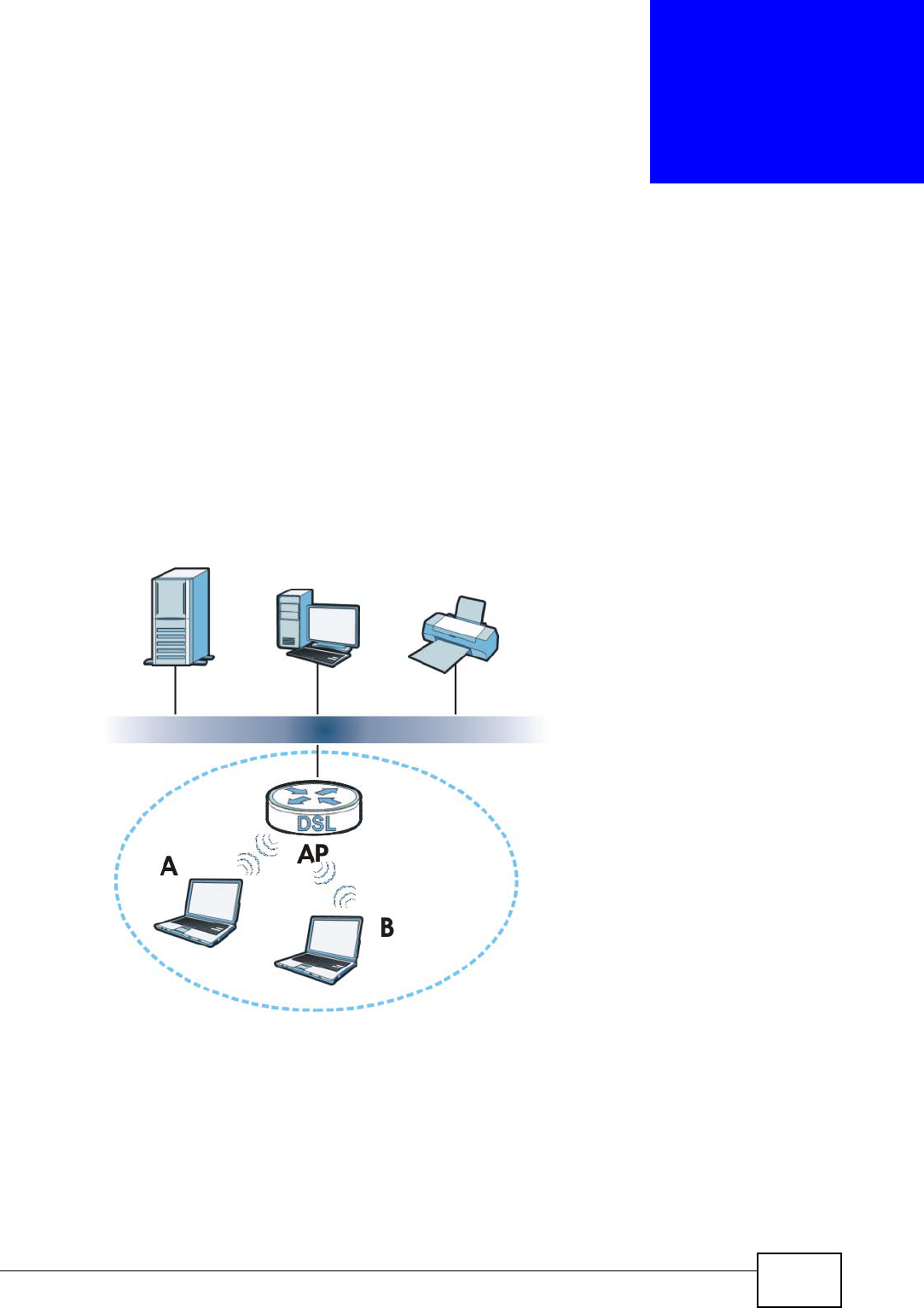
The following figure provides an example of a wireless network.
Figure 74 Example of a Wireless Network
The wireless network is the part in the blue circle. In this wireless network,
devices A and B are called wireless clients. The wireless clients use the access
point (AP) to interact with other devices (such as the printer) or with the Internet.
Your NBG4615 is the AP.

Chapter 14 Wireless LAN
NBG4615 User’s Guide
130
14.1.1 What You Can Do
•Use the General screen to enter the SSID, enable intra-BSS traffic and select
the channel. (Section 14.2 on page 133).
•Use the Security screen to configure wireless security between the NBG4615
and the wireless clients.
•Use the MAC Filter screen to allow or deny wireless stations based on their
MAC addresses from connecting to the NBG4615 (Section 14.4 on page 139).
•Use the Advanced screen to allow intra-BSS networking and set the RTS/CTS
Threshold (Section 14.5 on page 140).
•Use the QoS screen to ensure Quality of Service (QoS) in your wireless network
(Section 14.6 on page 141).
•Use the WPS screen to quickly set up a wireless network with strong security,
without having to configure security settings manually (Section 14.7 on page
142).
•Use the WPS Station screen to add a wireless station using WPS (Section 14.8
on page 143).
•Use the Scheduling screen to set the times your wireless LAN is turned on and
off (Section 14.9 on page 144).
•Use the WDS screen to configure Wireless Distribution System on your
NBG4615 (Section 14.10 on page 146).
14.1.2 What You Should Know
Every wireless network must follow these basic guidelines.
• Every wireless client in the same wireless network must use the same SSID.
The SSID is the name of the wireless network. It stands for Service Set IDentity.
• If two wireless networks overlap, they should use different channels.
Like radio stations or television channels, each wireless network uses a specific
channel, or frequency, to send and receive information.
• Every wireless client in the same wireless network must use security compatible
with the AP.
Security stops unauthorized devices from using the wireless network. It can also
protect the information that is sent in the wireless network.
Wireless Security Overview
The following sections introduce different types of wireless security you can set up
in the wireless network.

Chapter 14 Wireless LAN
NBG4615 User’s Guide 131
SSID
Normally, the AP acts like a beacon and regularly broadcasts the SSID in the area.
You can hide the SSID instead, in which case the AP does not broadcast the SSID.
In addition, you should change the default SSID to something that is difficult to
guess.
This type of security is fairly weak, however, because there are ways for
unauthorized devices to get the SSID. In addition, unauthorized devices can still
see the information that is sent in the wireless network.
MAC Address Filter
Every wireless client has a unique identification number, called a MAC address.1 A
MAC address is usually written using twelve hexadecimal characters2; for
example, 00A0C5000002 or 00:A0:C5:00:00:02. To get the MAC address for each
wireless client, see the appropriate User’s Guide or other documentation.
You can use the MAC address filter to tell the AP which wireless clients are allowed
or not allowed to use the wireless network. If a wireless client is allowed to use the
wireless network, it still has to have the correct settings (SSID, channel, and
security). If a wireless client is not allowed to use the wireless network, it does not
matter if it has the correct settings.
This type of security does not protect the information that is sent in the wireless
network. Furthermore, there are ways for unauthorized devices to get the MAC
address of an authorized wireless client. Then, they can use that MAC address to
use the wireless network.
User Authentication
You can make every user log in to the wireless network before they can use it.
This is called user authentication. However, every wireless client in the wireless
network has to support IEEE 802.1x to do this.
For wireless networks, there are two typical places to store the user names and
passwords for each user.
• In the AP: this feature is called a local user database or a local database.
• In a RADIUS server: this is a server used in businesses more than in homes.
If your AP does not provide a local user database and if you do not have a RADIUS
server, you cannot set up user names and passwords for your users.
1. Some wireless devices, such as scanners, can detect wireless networks but cannot use wireless networks.
These kinds of wireless devices might not have MAC addresses.
2. Hexadecimal characters are 0, 1, 2, 3, 4, 5, 6, 7, 8, 9, A, B, C, D, E, and F.

Chapter 14 Wireless LAN
NBG4615 User’s Guide
132
Unauthorized devices can still see the information that is sent in the wireless
network, even if they cannot use the wireless network. Furthermore, there are
ways for unauthorized wireless users to get a valid user name and password.
Then, they can use that user name and password to use the wireless network.
Local user databases also have an additional limitation that is explained in the
next section.
Encryption
Wireless networks can use encryption to protect the information that is sent in the
wireless network. Encryption is like a secret code. If you do not know the secret
code, you cannot understand the message.
The types of encryption you can choose depend on the type of user
authentication. (See page 131 for information about this.)
For example, if the wireless network has a RADIUS server, you can choose WPA
or WPA2. If users do not log in to the wireless network, you can choose no
encryption, Static WEP, WPA-PSK, or WPA2-PSK.
Usually, you should set up the strongest encryption that every wireless client in
the wireless network supports. For example, suppose the AP does not have a local
user database, and you do not have a RADIUS server. Therefore, there is no user
authentication. Suppose the wireless network has two wireless clients. Device A
only supports WEP, and device B supports WEP and WPA. Therefore, you should
set up Static WEP in the wireless network.
Note: It is recommended that wireless networks use WPA-PSK, WPA, or stronger
encryption. IEEE 802.1x and WEP encryption are better than none at all, but it
is still possible for unauthorized devices to figure out the original information
pretty quickly.
Note: It is not possible to use WPA-PSK, WPA or stronger encryption with a local user
database. In this case, it is better to set up stronger encryption with no
authentication than to set up weaker encryption with the local user database.
When you select WPA2 or WPA2-PSK in your NBG4615, you can also select an
option (WPA Compatible) to support WPA as well. In this case, if some wireless
clients support WPA and some support WPA2, you should set up WPA2-PSK or
Table 41 Types of Encryption for Each Type of Authentication
NO AUTHENTICATION RADIUS SERVER
Weakest No Security WPA
Static WEP
WPA-PSK
Strongest WPA2-PSK WPA2

Chapter 14 Wireless LAN
NBG4615 User’s Guide 133
WPA2 (depending on the type of wireless network login) and select the WPA
Compatible option in the NBG4615.
Many types of encryption use a key to protect the information in the wireless
network. The longer the key, the stronger the encryption. Every wireless client in
the wireless network must have the same key.
WPS
WiFi Protected Setup (WPS) is an industry standard specification, defined by the
WiFi Alliance. WPS allows you to quickly set up a wireless network with strong
security, without having to configure security settings manually. Depending on the
devices in your network, you can either press a button (on the device itself, or in
its configuration utility) or enter a PIN (Personal Identification Number) in the
devices. Then, they connect and set up a secure network by themselves. See how
to set up a secure wireless network using WPS in the Section 13.2 on page 111.
WDS
Wireless Distribution System or WDS security is used between bridged APs. It is
independent of the security between the wired networks and their respective APs.
If you do not enable WDS security, traffic between APs is not encrypted. When
WDS security is enabled, both APs must use the same pre-shared key.
14.2 General Wireless LAN Screen
Use this screen to configure the SSIDs of the wireless LAN.
Note: If you are configuring the NBG4615 from a computer connected to the wireless
LAN and you change the NBG4615’s SSID, channel or security settings, you
will lose your wireless connection when you press Apply to confirm. You must
then change the wireless settings of your computer to match the NBG4615’s
new settings.
Chapter 14 Wireless LAN
NBG4615 User’s Guide
134
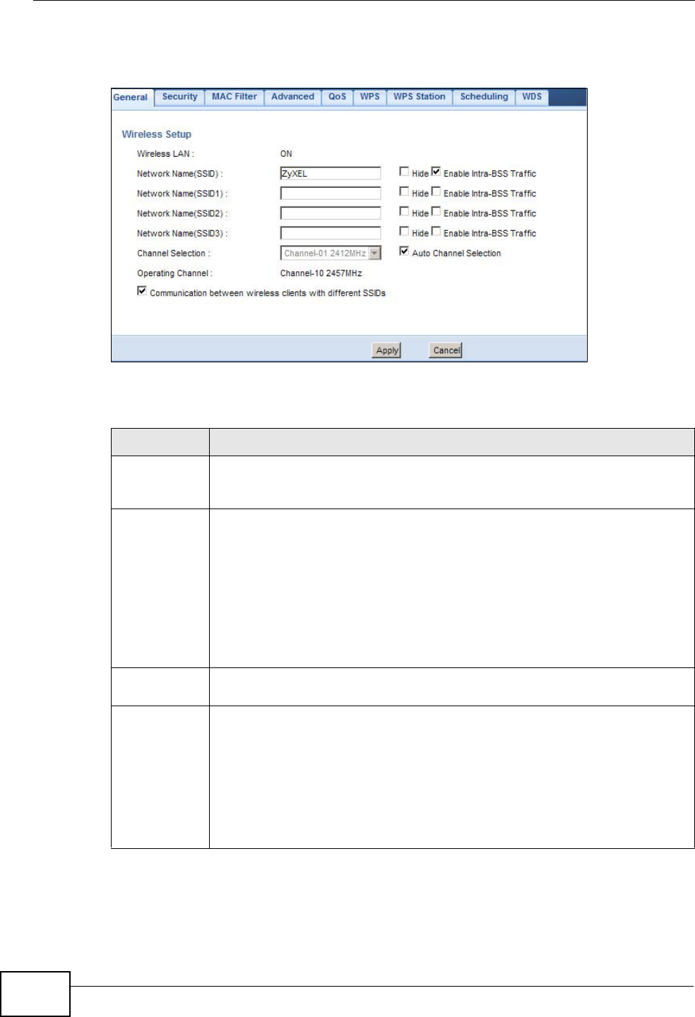
Click Network > Wireless LAN to open the General screen.
Figure 75 Network > Wireless LAN > General
The following table describes the general wireless LAN labels in this screen.
Table 42 Network > Wireless LAN > General
LABEL DESCRIPTION
Wireless LAN This shows whether the wireless LAN is ON or OFF. You can enable or
disable the wireless LAN by using the WLAN switch located on the back
panel of the NBG4615.
Network
Name(SSID)
or
Name(SSID1
~3)
The SSID (Service Set IDentity) identifies the Service Set with which a
wireless client is associated. Enter a descriptive name (up to 32 printable
characters found on a typical English language keyboard) for the wireless
LAN.
You can configure up to four SSIDs to enable multiple BSSs (Basic Service
Sets) on the NBG4615. This allows you to use one access point to provide
several BSSs simultaneously. You can then assign varying security types
to different SSIDs. Wireless clients can use different SSIDs to associate
with the same access point.
Hide SSID Select this check box to hide the SSID in the outgoing beacon frame so a
station cannot obtain the SSID through scanning using a site survey tool.
Enable Intra-
BSS Traffic A Basic Service Set (BSS) exists when all communications between
wireless clients or between a wireless client and a wired network client go
through one access point (AP).
Intra-BSS traffic is traffic between wireless clients in the BSS. When Intra-
BSS is enabled, wireless clients can access the wired network and
communicate with each other. When Intra-BSS is disabled, wireless clients
can still access the wired network but cannot communicate with each
other.

Chapter 14 Wireless LAN
NBG4615 User’s Guide 135
See the rest of this chapter for information on the other labels in this screen.
14.3 Wireless Security Screen
Use this screen to select the wireless security mode for each SSID. Click Network
> Wireless LAN > Security to open the Security screen. The screen varies
depending on what you select in the Security Mode field.
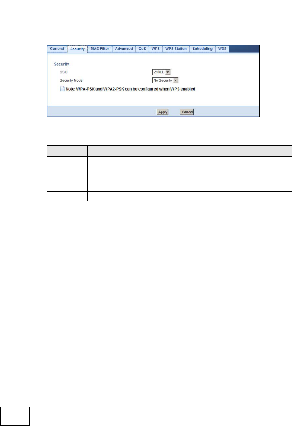
14.3.1 No Security
Select No Security to allow wireless clients to communicate with the access
points without any data encryption.
Channel
Selection Set the operating frequency/channel depending on your particular region.
Select a channel from the drop-down list box. The options vary depending
on the frequency band and the country you are in.
Refer to the Connection Wizard chapter for more information on channels.
This option is only available if Auto Channel Selection is disabled.
Auto Channel
Selection Select this check box for the NBG4615 to automatically choose the
channel with the least interference. Deselect this check box if you wish to
manually select the channel using the Channel Section field.
Operating
Channel This displays the channel the NBG4615 is currently using.
Communicati
on between
wireless
clients with
different
SSIDs
Select the check box to allow communication between wireless clients of
different SSIDs. Do not select the check box if you do not want to enable
this function.
Apply Click Apply to save your changes back to the NBG4615.
Cancel Click Cancel to reload the previous configuration for this screen.
Table 42 Network > Wireless LAN > General (continued)
LABEL DESCRIPTION
Chapter 14 Wireless LAN
NBG4615 User’s Guide
136
Note: If you do not enable any wireless security on your NBG4615, your network is
accessible to any wireless networking device that is within range.
Figure 76 Network > Wireless LAN > Security: No Security
The following table describes the labels in this screen.
14.3.2 WEP Encryption
WEP encryption scrambles the data transmitted between the wireless stations and
the access points to keep network communications private. It encrypts unicast
and multicast communications in a network. Both the wireless stations and the
access points must use the same WEP key.
Your NBG4615 allows you to configure up to four 64-bit or 128-bit WEP keys but
only one key can be enabled at any one time.
Table 43 Network > Wireless LAN > Security: No Security
LABEL DESCRIPTION
SSID Select the SSID for which you want to configure the security.
Security
Mode Choose No Security from the drop-down list box.
Apply Click Apply to save your changes back to the NBG4615.
Cancel Click Cancel to reload the previous configuration for this screen.
Chapter 14 Wireless LAN
NBG4615 User’s Guide 137
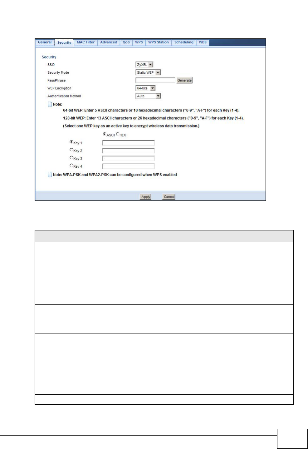
Select Static WEP from the Security Mode list.
Figure 77 Network > Wireless LAN > Security: Static WEP
The following table describes the wireless LAN security labels in this screen.
Table 44 Network > Wireless LAN > Security: Static WEP
LABEL DESCRIPTION
SSID Select the SSID for which you want to configure the security.
Security Mode Select Static WEP to enable data encryption.
PassPhrase Enter a Passphrase (up to 26 printable characters) and click Generate.
A passphrase functions like a password. In WEP security mode, it is
further converted by the NBG4615 into a complicated string that is
referred to as the “key”. This key is requested from all devices wishing to
connect to a wireless network.
WEP
Encryption Select 64-bits or 128-bits.
This dictates the length of the security key that the network is going to
use.
Authentication
Method Select Auto or Shared Key from the drop-down list box.
This field specifies whether the wireless clients have to provide the WEP
key to login to the wireless client. Keep this setting at Auto unless you
want to force a key verification before communication between the
wireless client and the NBG4615 occurs.
Select Shared Key to force the clients to provide the WEP key prior to
communication.
ASCII Select this option in order to enter ASCII characters as WEP key.
Chapter 14 Wireless LAN
NBG4615 User’s Guide
138
14.3.3 WPA-PSK/WPA2-PSK
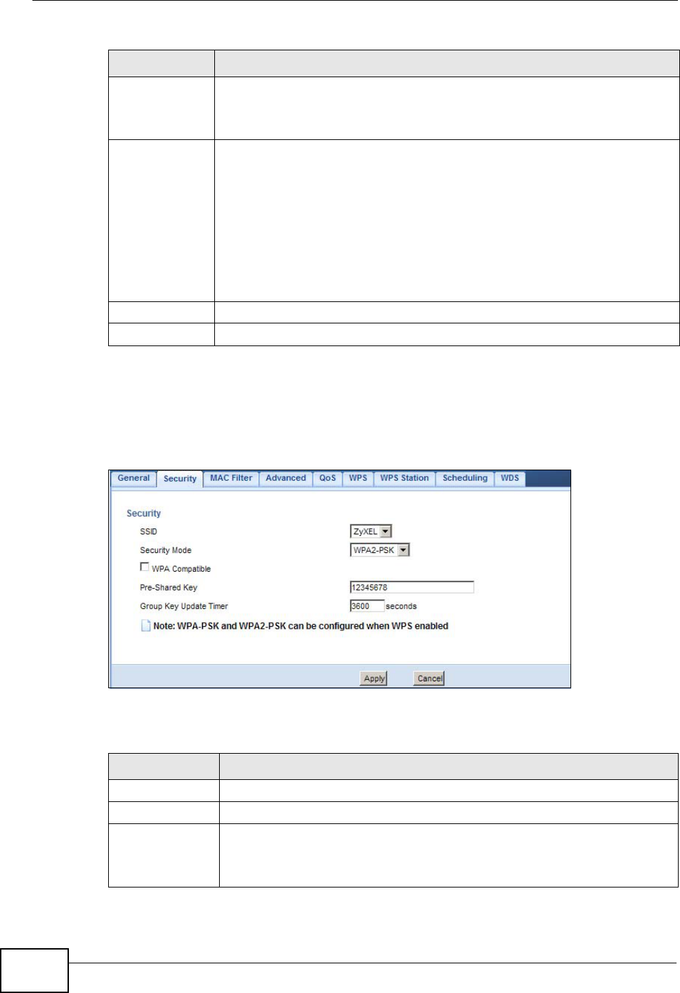
Select WPA-PSK or WPA2-PSK from the Security Mode list.
Figure 78 Network > Wireless LAN > Security: WPA-PSK/WPA2-PSK
The following table describes the labels in this screen.
Hex Select this option in order to enter hexadecimal characters as a WEP key.
The preceding "0x", that identifies a hexadecimal key, is entered
automatically.
Key 1 to Key 4 The WEP keys are used to encrypt data. Both the NBG4615 and the
wireless stations must use the same WEP key for data transmission.
If you chose 64-bit WEP, then enter any 5 ASCII characters or 10
hexadecimal characters ("0-9", "A-F").
If you chose 128-bit WEP, then enter 13 ASCII characters or 26
hexadecimal characters ("0-9", "A-F").
You must configure at least one key, only one key can be activated at
any one time. The default key is key 1.
Apply Click Apply to save your changes back to the NBG4615.
Cancel Click Cancel to reload the previous configuration for this screen.
Table 44 Network > Wireless LAN > Security: Static WEP (continued)
LABEL DESCRIPTION
Table 45 Network > Wireless LAN > Security: WPA-PSK/WPA2-PSK
LABEL DESCRIPTION
SSID Select the SSID for which you want to configure the security.
Security Mode Select WPA-PSK or WPA2-PSK to enable data encryption.
WPA
Compatible This field appears when you choose WPA2-PSK as the Security Mode.
Check this field to allow wireless devices using WPA-PSK security
mode to connect to your NBG4615.
Chapter 14 Wireless LAN
NBG4615 User’s Guide 139
14.4 MAC Filter
The MAC filter screen allows you to configure the NBG4615 to give exclusive
access to devices (Allow) or exclude devices from accessing the NBG4615 (Deny).
Every Ethernet device has a unique MAC (Media Access Control) address. The MAC
address is assigned at the factory and consists of six pairs of hexadecimal
characters, for example, 00:A0:C5:00:00:02. You need to know the MAC address
of the devices to configure this screen.
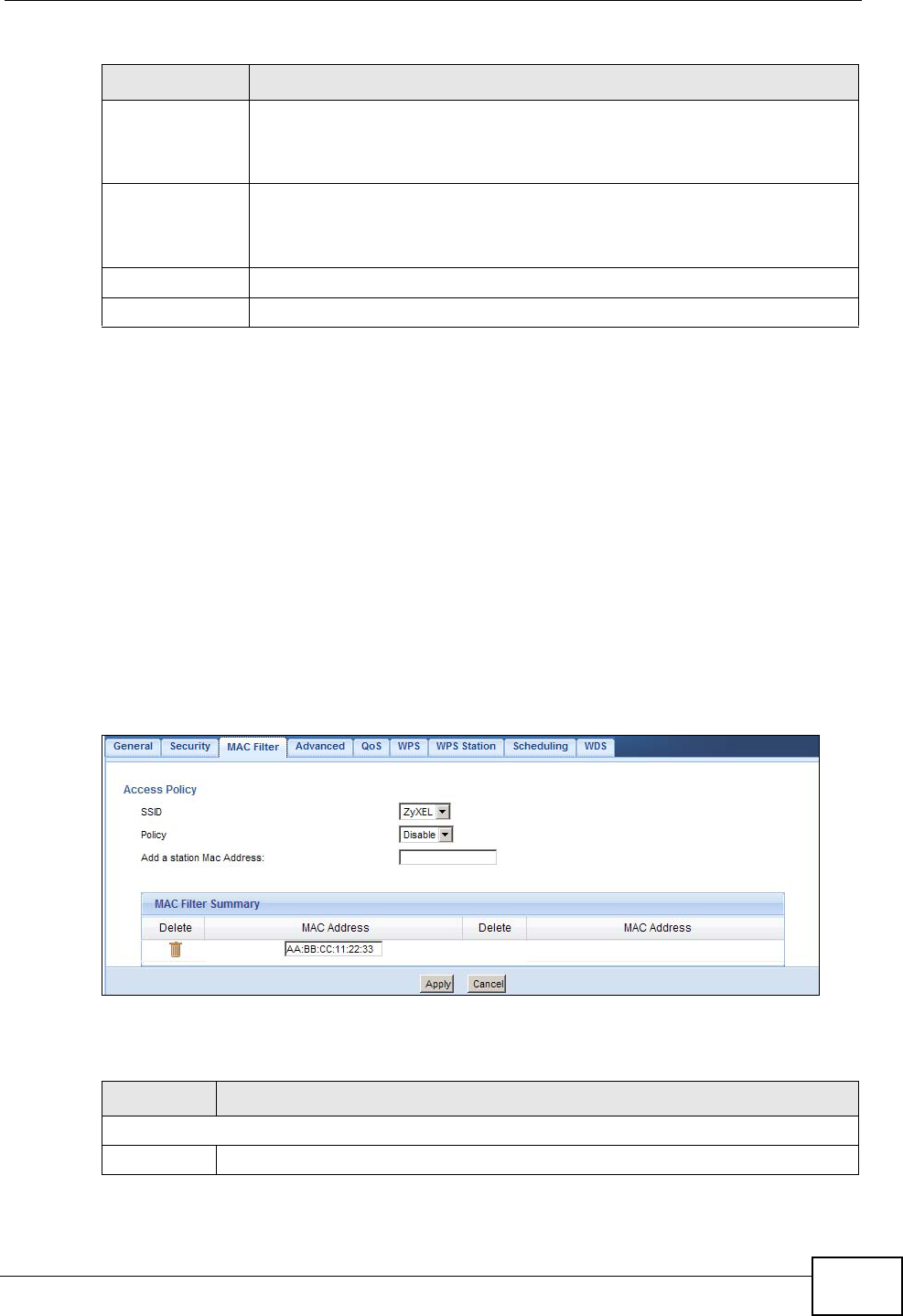
To change your NBG4615’s MAC filter settings, click Network > Wireless LAN >
MAC Filter. The screen appears as shown.
Figure 79 Network > Wireless LAN > MAC Filter
The following table describes the labels in this menu.
Pre-Shared Key WPA-PSK/WPA2-PSK uses a simple common password for
authentication.
Type a pre-shared key from 8 to 63 case-sensitive keyboard characters.
Group Key
Update Timer The Group Key Update Timer is the rate at which the AP sends a new
group key out to all clients.
The default is 3600 seconds (60 minutes).
Apply Click Apply to save your changes back to the NBG4615.
Cancel Click Cancel to reload the previous configuration for this screen.
Table 45 Network > Wireless LAN > Security: WPA-PSK/WPA2-PSK (continued)
LABEL DESCRIPTION
Table 46 Network > Wireless LAN > MAC Filter
LABEL DESCRIPTION
Access Policy
SSID Select the SSID for which you want to configure MAC filtering.
Chapter 14 Wireless LAN
NBG4615 User’s Guide
140
14.5 Wireless LAN Advanced Screen
Use this screen to allow wireless advanced features, such as the output power,
RTS/CTS Threshold and high-throughput physical mode settings.
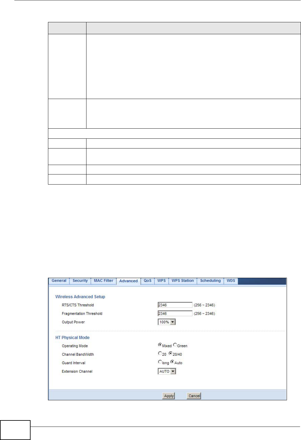
Click Network > Wireless LAN > Advanced. The screen appears as shown.
Figure 80 Network > Wireless LAN > Advanced
Policy Define the filter action for the list of MAC addresses in the MAC Address
table.
Select Disable to deactivate the MAC filtering rule you configure below.
Select Allow to permit access to the NBG4615, MAC addresses not listed
will be denied access to the NBG4615.
Select Reject to block access to the NBG4615, MAC addresses not listed
will be allowed to access the NBG4615
Add a
station Mac
Address
Enter the MAC addresses of the wireless station that are allowed or denied
access to the NBG4615 in these address fields. Enter the MAC addresses in
a valid MAC address format, that is, six hexadecimal character pairs, for
example, 12:34:56:78:9a:bc. Click Add.
MAC Filter Summary
Delete Click the delete icon to remove the MAC address from the list.
MAC
Address This is the MAC address of the wireless station that are allowed or denied
access to the NBG4615.
Apply Click Apply to save your changes back to the NBG4615.
Cancel Click Cancel to reload the previous configuration for this screen.
Table 46 Network > Wireless LAN > MAC Filter (continued)
LABEL DESCRIPTION

Chapter 14 Wireless LAN
NBG4615 User’s Guide 141
The following table describes the labels in this screen.
14.6 Quality of Service (QoS) Screen
The QoS screen allows you to automatically give a service (such as VoIP and
video) a priority level.
Table 47 Network > Wireless LAN > Advanced
LABEL DESCRIPTION
RTS/CTS
Threshold Data with its frame size larger than this value will perform the RTS
(Request To Send)/CTS (Clear To Send) handshake.
Enter a value between 256 and 2432.
Fragmentation
Threshold The threshold (number of bytes) for the fragmentation boundary for
directed messages. It is the maximum data fragment size that can be
sent. Enter an even number between 256 and 2346.
Output Power Set the output power of the NBG4615 in this field. If there is a high
density of APs in an area, decrease the output power of the NBG4615 to
reduce interference with other APs. Select one of the following 100%,
90%, 75%, 50%, 25% or 10%. See the product specifications for
more information on your NBG4615’s output power.
HT (High Throughput) Physical Mode - Use the fields below to configure the 802.11
wireless environment of your NBG4615.
Operating
Mode Choose this according to the wireless mode(s) used in your network.
Mixed - Select this if the wireless clients in your network use different
wireless modes (for example, IEEE 802.11b/g and IEEE 802.1n modes)
Green - Select this if the wireless clients in your network uses only one
type of wireless mode (for example, IEEEE 802.11 n only)
Channel
Bandwidth Select the channel bandwidth you want to use for your wireless network.
It is recommended that you select 20/40 (20/40 MHz).
Select 20 MHz if you want to lessen radio interference with other
wireless devices in your neighborhood.
Guard Interval Select Auto to increase data throughput. However, this may make data
transfer more prone to errors.
Select Long to prioritize data integrity. This may be because your
wireless network is busy and congested or the NBG4615 is located in an
environment prone to radio interference.
Extension
Channel This is set to Auto by default.
If you select 20/40 as your Channel Bandwidth, the extension
channel enables the NBG4615 to get higher data throughput. This also
lowers radio interference and traffic.
Apply Click Apply to save your changes back to the NBG4615.
Cancel Click Cancel to reload the previous configuration for this screen.
Chapter 14 Wireless LAN
NBG4615 User’s Guide
142
Click Network > Wireless LAN > QoS. The following screen appears.
Figure 81 Network > Wireless LAN > QoS
The following table describes the labels in this screen.
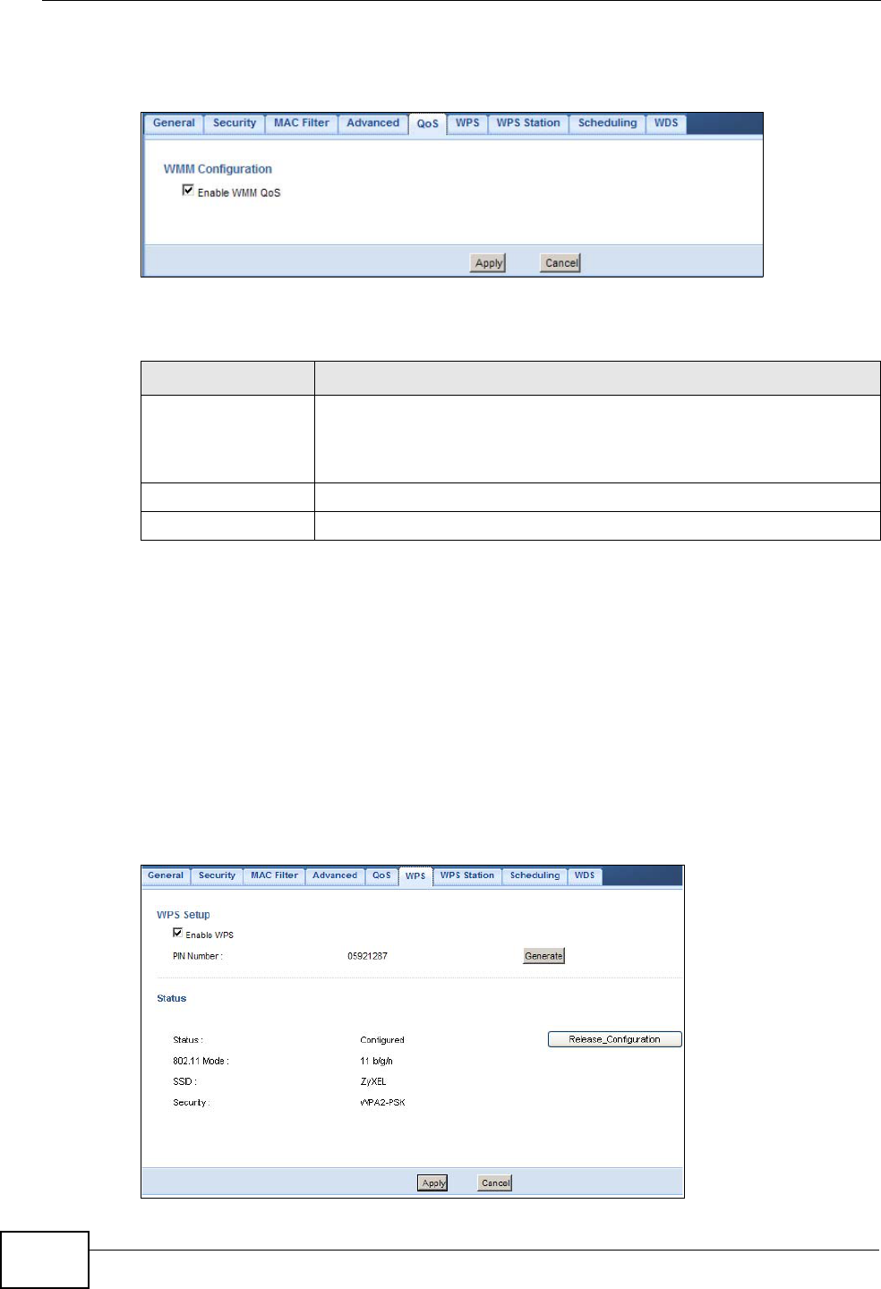
14.7 WPS Screen
Use this screen to enable/disable WPS, view or generate a new PIN number and
check current WPS status. To open this screen, click Network > Wireless LAN >
WPS tab.
Note: With WPS, wireless clients can only connect to the wireless network using the
first SSID on the NBG4615.
Figure 82 Network > Wireless LAN > WPS
Table 48 Network > Wireless LAN > QoS
LABEL DESCRIPTION
Enable WMM QoS Check this to have the NBG4615 automatically give a service a
priority level according to the ToS value in the IP header of packets
it sends. WMM QoS (Wifi MultiMedia Quality of Service) gives high
priority to voice and video, which makes them run more smoothly.
Apply Click Apply to save your changes to the NBG4615.
Cancel Click Cancel to reload the previous configuration for this screen.

Chapter 14 Wireless LAN
NBG4615 User’s Guide 143
The following table describes the labels in this screen.
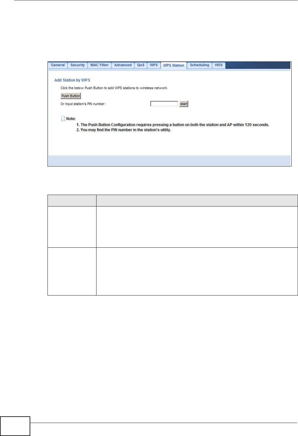
14.8 WPS Station Screen
Use this screen when you want to add a wireless station using WPS. To open this
screen, click Network > Wireless LAN > WPS Station tab.
Table 49 Network > Wireless LAN > WPS
LABEL DESCRIPTION
WPS Setup
Enable WPS Select this to enable the WPS feature.
PIN Number This displays a PIN number last time system generated. Click Generate
to generate a new PIN number.
Status
Status This displays Configured when the NBG4615 has connected to a
wireless network using WPS or when Enable WPS is selected and
wireless or wireless security settings have been changed. The current
wireless and wireless security settings also appear in the screen.
This displays Unconfigured if WPS is disabled and there are no
wireless or wireless security changes on the NBG4615 or you click
Release_Configuration to remove the configured wireless and
wireless security settings.
Release
Configuration This button is only available when the WPS status displays Configured.
Click this button to remove all configured wireless and wireless security
settings for WPS connections on the NBG4615.
802.11 Mode This is the 802.11 mode used. Only compliant WLAN devices can
associate with the NBG4615.
SSID This is the name of the wireless network (the NBG4615’s first SSID).
Security This is the type of wireless security employed by the network.
Apply Click Apply to save your changes back to the NBG4615.
Cancel Click Cancel to reload the previous configuration for this screen.
Chapter 14 Wireless LAN
NBG4615 User’s Guide
144
Note: After you click Push Button on this screen, you have to press a similar button
in the wireless station utility within 2 minutes. To add the second wireless
station, you have to press these buttons on both device and the wireless station
again after the first 2 minutes.
Figure 83 Network > Wireless LAN > WPS Station
The following table describes the labels in this screen.
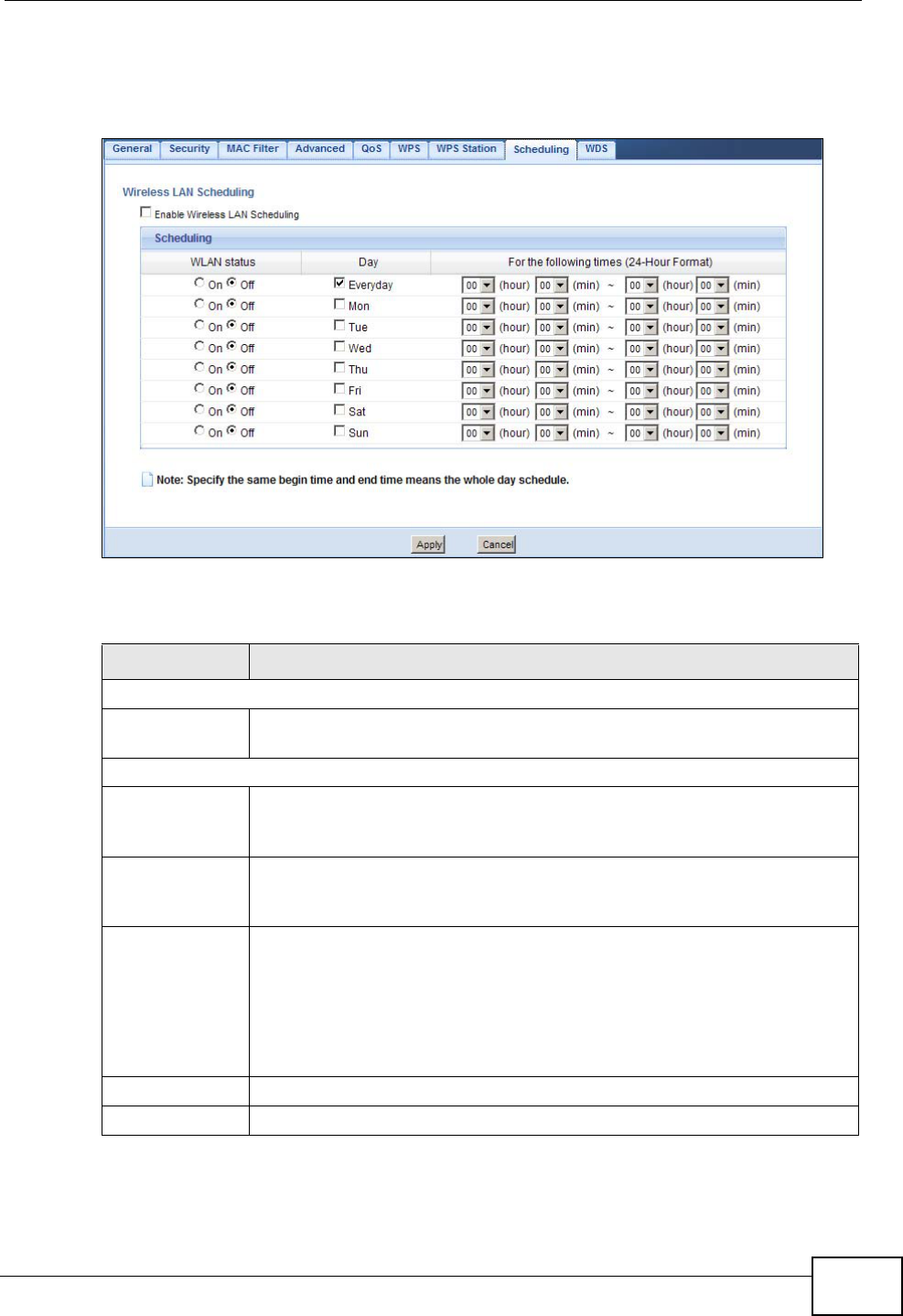
14.9 Scheduling Screen
Use this screen to set the times your wireless LAN is turned on and off. Wireless
LAN scheduling is disabled by default. The wireless LAN can be scheduled to turn
Table 50 Network > Wireless LAN > WPS Station
LABEL DESCRIPTION
Push Button Use this button when you use the PBC (Push Button Configuration)
method to configure wireless stations’s wireless settings. See Section
4.3.1 on page 32.
Click this to start WPS-aware wireless station scanning and the wireless
security information synchronization.
Or input
station’s PIN
number
Use this button when you use the PIN Configuration method to
configure wireless station’s wireless settings. See Section 4.3.2 on page
33.
Type the same PIN number generated in the wireless station’s utility.
Then click Start to associate to each other and perform the wireless
security information synchronization.
Chapter 14 Wireless LAN
NBG4615 User’s Guide 145
on or off on certain days and at certain times. To open this screen, click Network
> Wireless LAN > Scheduling tab.
Figure 84 Network > Wireless LAN > Scheduling
The following table describes the labels in this screen.
Table 51 Network > Wireless LAN > Scheduling
LABEL DESCRIPTION
Wireless LAN Scheduling
Enable Wireless
LAN Scheduling Select this to enable Wireless LAN scheduling.
Scheduling
WLAN Status Select On or Off to specify whether the Wireless LAN is turned on or off.
This field works in conjunction with the Day and For the following
times fields.
Day Select Everyday or the specific days to turn the Wireless LAN on or off.
If you select Everyday you can not select any specific days. This field
works in conjunction with the For the following times field.
For the
following times
(24-Hour
Format)
Select a begin time using the first set of hour and minute (min) drop
down boxes and select an end time using the second set of hour and
minute (min) drop down boxes. If you have chosen On earlier for the
WLAN Status the Wireless LAN will turn on between the two times you
enter in these fields. If you have chosen Off earlier for the WLAN Status
the Wireless LAN will turn off between the two times you enter in these
fields.
Apply Click Apply to save your changes back to the NBG4615.
Cancel Click Cancel to reload the previous configuration for this screen.
Chapter 14 Wireless LAN
NBG4615 User’s Guide
146
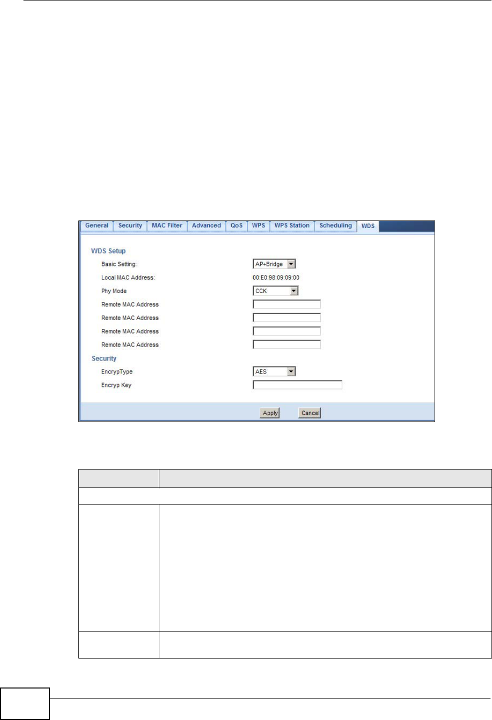
14.10 WDS Screen
A Wireless Distribution System (WDS) is a wireless connection between two or
more APs. Use this screen to set the operating mode of your NBG4615 to AP +
Bridge or Bridge and establish wireless links with other APs. You need to know
the MAC address of the peer device, which also must be in bridge mode.
Note: You must enable the same wireless security settings on the NBG4615 and on
all wireless clients that you want to associate with it.
Click Network > Wireless LAN > WDS tab. The following screen opens with the
Basic Setting set to Disabled, and Security Mode set to No Security.
Figure 85 Network > Wireless LAN > WDS
The following table describes the labels in this screen.
Table 52 Network > Wireless LAN > WDS
LABEL DESCRIPTION
WDS Setup
Basic Settings Select the operating mode for your NBG4615.
•Disable - The NBG4615 works as an access point only and cannot
establish wireless links with other APs.
•AP + Bridge - The NBG4615 functions as a bridge and access point
simultaneously.
•Bridge - The NBG4615 acts as a wireless network bridge and
establishes wireless links with other APs.
You need to know the MAC address of the peer device, which also must
be in bridge mode. The NBG4615 can establish up to five wireless links
with other APs.
Local MAC
Address This is the MAC address of your NBG4615.

Chapter 14 Wireless LAN
NBG4615 User’s Guide 147
Phy Mode Select the Phy mode you want the NBG4615 to use. This dictates the
maximum size of packets during data transmission.
This field is not available when you select Disable in the Basic Setting
field.
Remote MAC
Address This is the MAC address of the peer device that your NBG4615 wants to
make a bridge connection with.
You can connect to up to 4 peer devices.
Security
EncrypType Select whether to use WEP, TKIP or AES encryption for your WDS
connection in this field.
Otherwise, select No Security.
EncrypKey The Encryp Key is used to encrypt data. Peers must use the same key
for data transmission.
Apply Click Apply to save your changes to NBG4615.
Cancel Click Cancel to reload the previous configuration for this screen.
Table 52 Network > Wireless LAN > WDS (continued)
LABEL DESCRIPTION

Chapter 14 Wireless LAN
NBG4615 User’s Guide
148

NBG4615 User’s Guide 149
CHAPTER 15
IPv6
15.1 Overview
IPv6 (Internet Protocol version 6), is designed to enhance IP address size and
features. The increase in IPv6 address size to 128 bits (from the 32-bit IPv4
address) allows up to 3.4 x 1038 IP addresses.
• See Appendix G on page 325 for more information on IPv6.
15.1.1 What You Need to Know
IPv6 Addressing
The 128-bit IPv6 address is written as eight 16-bit hexadecimal blocks separated
by colons (:). This is an example IPv6 address
2001:0db8:1a2b:0015:0000:0000:1a2f:0000.
IPv6 addresses can be abbreviated in two ways:
• Leading zeros in a block can be omitted. So
2001:0db8:1a2b:0015:0000:0000:1a2f:0000 can be written as
2001:db8:1a2b:15:0:0:1a2f:0.
• Any number of consecutive blocks of zeros can be replaced by a double colon. A
double colon can only appear once in an IPv6 address. So
2001:0db8:0000:0000:1a2f:0000:0000:0015 can be written as
2001:0db8::1a2f:0000:0000:0015, 2001:0db8:0000:0000:1a2f::0015,
2001:db8::1a2f:0:0:15 or 2001:db8:0:0:1a2f::15.
IPv6 Prefix and Prefix Length
Similar to an IPv4 subnet mask, IPv6 uses an address prefix to represent the
network address. An IPv6 prefix length specifies how many most significant bits
(start from the left) in the address compose the network address. The prefix
length is written as “/x” where x is a number. For example,
2001:db8:1a2b:15::1a2f:0/32
means that the first 32 bits (2001:db8) is the subnet prefix.
Chapter 15 IPv6
NBG4615 User’s Guide
150
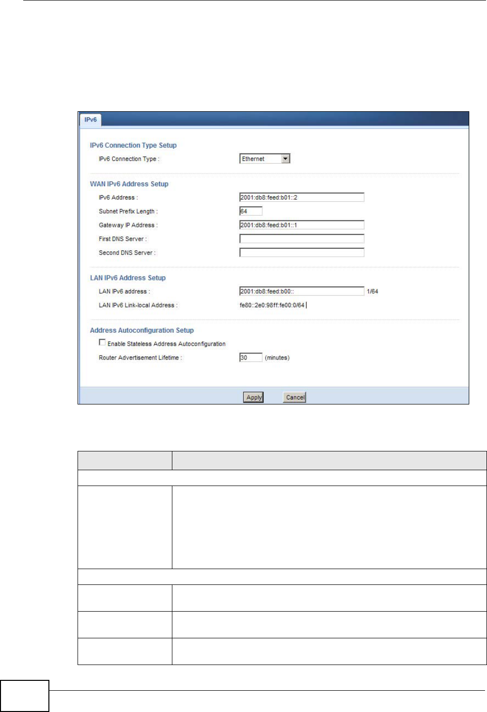
15.2 The IPv6 Screen
Click Network > IPv6 to open the IPv6 screen. Use this screen to configure the
IPv6 settings for your NBG4615.
Figure 86 Network > IPv6
The following table describes the fields in this screen.
Table 53 Network > IPv6
LABEL DESCRIPTION
IPv6 Connection Type Setup
IPv6 Connection
Type Select the IPv6 connection type:
•Ethernet: Select this if your ISP provides you a static IPv6
address. You need to enter the IPv6 information below according
to what your ISP provided.
•Link-local only: Use this connection mode for the NBG4615 to
communicate with other IPv6 devices on the LAN side. You do not
need to configure the settings below if you choose this mode.
WAN IPv6 Address Setup
IPv6 Address Enter the static IPv6 address provided by your ISP using colon (:)
hexadecimal notation.
Subnet Prefix
Length Enter the bit number of the IPv6 subnet mask provided by your ISP.
Gateway IP
Address Enter the IPv6 address of the default outgoing gateway using a colon
(:) hexadecimal notation.

Chapter 15 IPv6
NBG4615 User’s Guide 151
First DNS Server Enter the primary DNS server's IP address in this field.
Second DNS
Server Enter the secondary DNS server's IP address in this field.
LAN IPv6 Address Setup
LAN IPv6 address Enter a valid IPv6 address for the LAN using colon (:) hexadecimal
notation.
LAN IPv6 Link-local
Address This shows the IPv6 link-local address that the NBG4615 generates
automatically.
Address Autoconfiguration Setup
Enable Stateless
Address
Autoconfiguration
Select the checkbox to enable Stateless Address Autoconfiguration
on the NBG4615.
If this function is enabled, IP addresses are not generated by a DHCP
server. They are formed by combining network prefixes with an
interface identifier, which are derived from embedded IEEE
Identifiers.
Router
Advertisement
Lifetime
Specify the lifetime of the router advertisement.
Router advertisement is a response to a router solicitation or a
periodical multicast advertisement from a router to advertise its
presence and other parameters, such as IPv6 prefix and DNS
information.
Apply Click Apply to save your changes back to the NBG4615.
Cancel Click Cancel to reload the previous configuration for this screen.
Table 53 Network > IPv6 (continued)
LABEL DESCRIPTION

Chapter 15 IPv6
NBG4615 User’s Guide
152
NBG4615 User’s Guide 153
CHAPTER 16
WAN
16.1 Overview
This chapter discusses the NBG4615’s WAN screens. Use these screens to
configure your NBG4615 for Internet access.
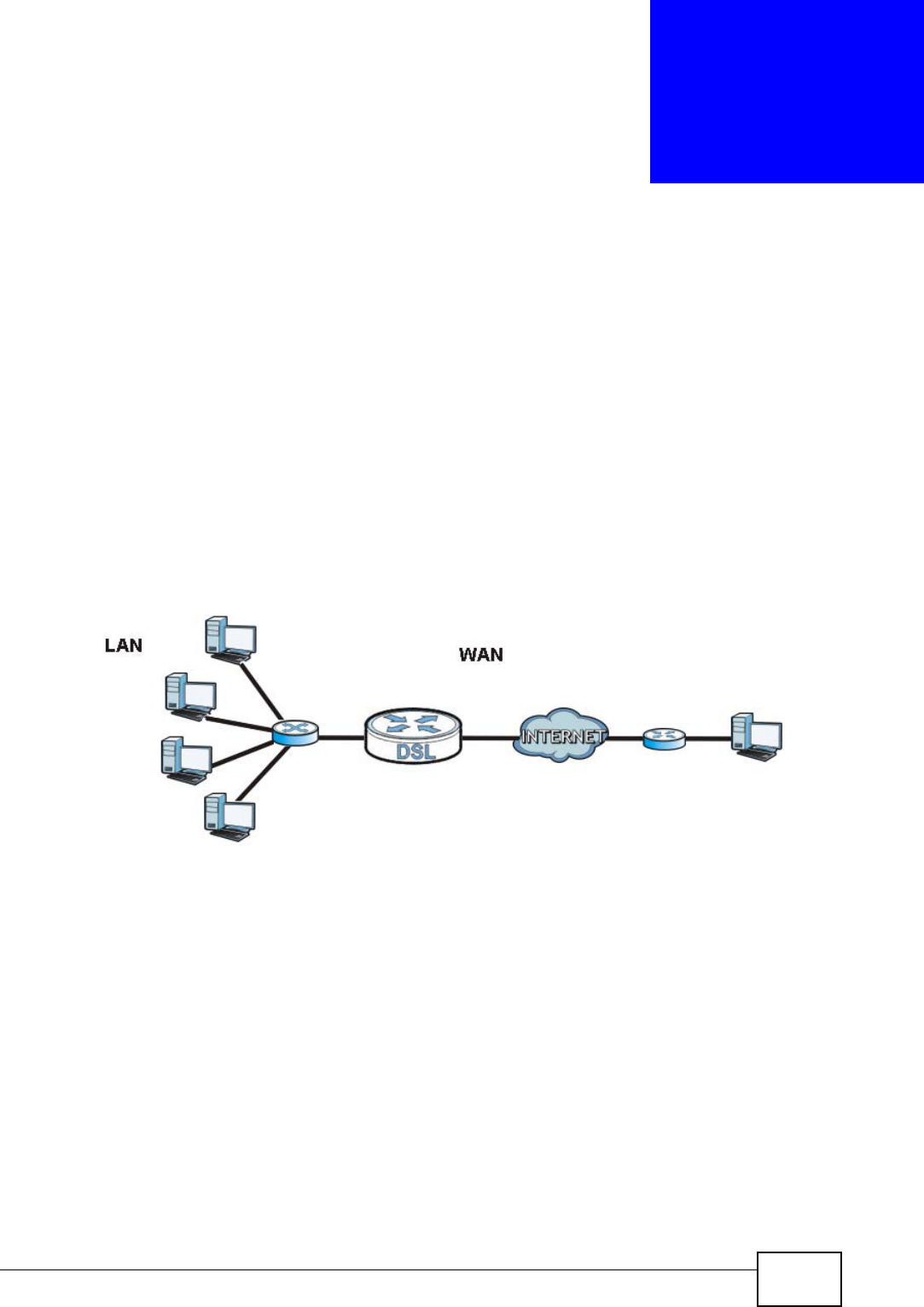
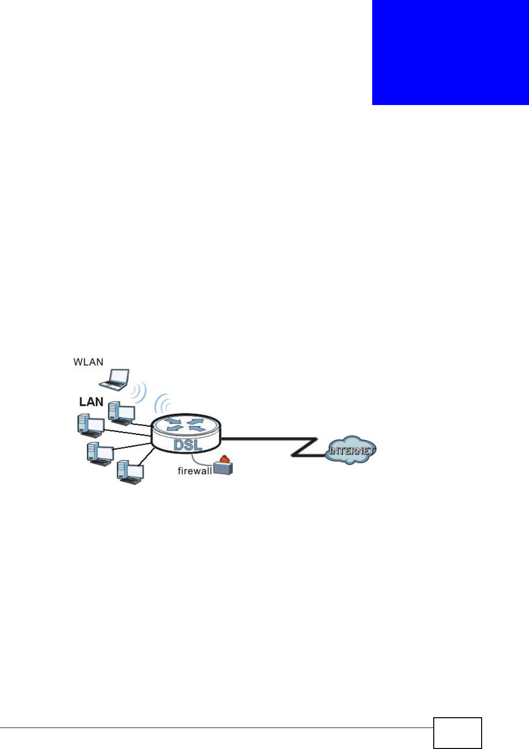
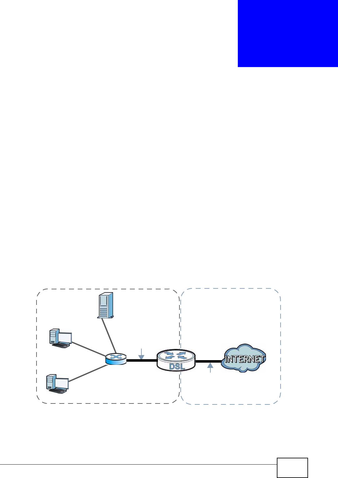
A WAN (Wide Area Network) connection is an outside connection to another
network or the Internet. It connects your private networks such as a LAN (Local
Area Network) and other networks, so that a computer in one location can
communicate with computers in other locations.
Figure 87 LAN and WAN
16.2 What You Can Do
•Use the Internet Connection screen to enter your ISP information and set
how the computer acquires its IP, DNS and WAN MAC addresses (Section 16.4
on page 156).
•Use the Advanced screen to enable multicasting, configure Windows
networking and bridge (Section 16.5 on page 166).
•Use IGMP Snooping screen to enable IGMP snooping in the LAN ports (Section
16.6 on page 167).

Chapter 16 WAN
NBG4615 User’s Guide
154
16.3 What You Need To Know
The information in this section can help you configure the screens for your WAN
connection, as well as enable/disable some advanced features of your NBG4615.
16.3.1 Configuring Your Internet Connection
Encapsulation Method
Encapsulation is used to include data from an upper layer protocol into a lower
layer protocol. To set up a WAN connection to the Internet, you need to use the
same encapsulation method used by your ISP (Internet Service Provider). If your
ISP offers a dial-up Internet connection using PPPoE (PPP over Ethernet) or PPTP
(Point-to-Point Tunneling Protocol), they should also provide a username and
password (and service name) for user authentication.
WAN IP Address
The WAN IP address is an IP address for the NBG4615, which makes it accessible
from an outside network. It is used by the NBG4615 to communicate with other
devices in other networks. It can be static (fixed) or dynamically assigned by the
ISP each time the NBG4615 tries to access the Internet.
If your ISP assigns you a static WAN IP address, they should also assign you the
subnet mask and DNS server IP address(es) (and a gateway IP address if you use
the Ethernet or ENET ENCAP encapsulation method).
DNS Server Address Assignment
Use Domain Name System (DNS) to map a domain name to its corresponding IP
address and vice versa, for instance, the IP address of www.zyxel.com is
204.217.0.2. The DNS server is extremely important because without it, you must
know the IP address of a computer before you can access it.
The NBG4615 can get the DNS server addresses in the following ways.
1The ISP tells you the DNS server addresses, usually in the form of an information
sheet, when you sign up. If your ISP gives you DNS server addresses, manually
enter them in the DNS server fields.
2If your ISP dynamically assigns the DNS server IP addresses (along with the
NBG4615’s WAN IP address), set the DNS server fields to get the DNS server
address from the ISP.
Chapter 16 WAN
NBG4615 User’s Guide 155
WAN MAC Address
The MAC address screen allows users to configure the WAN port's MAC address by
either using the factory default or cloning the MAC address from a computer on
your LAN. Choose Factory Default to select the factory assigned default MAC
Address.
Otherwise, click Clone the computer's MAC address - IP Address and enter
the IP address of the computer on the LAN whose MAC you are cloning. Once it is
successfully configured, the address will be copied to configuration file. It is
recommended that you clone the MAC address prior to hooking up the WAN Port.
16.3.2 Multicast
Traditionally, IP packets are transmitted in one of either two ways - Unicast (1
sender - 1 recipient) or Broadcast (1 sender - everybody on the network).
Multicast delivers IP packets to a group of hosts on the network - not everybody
and not just 1.
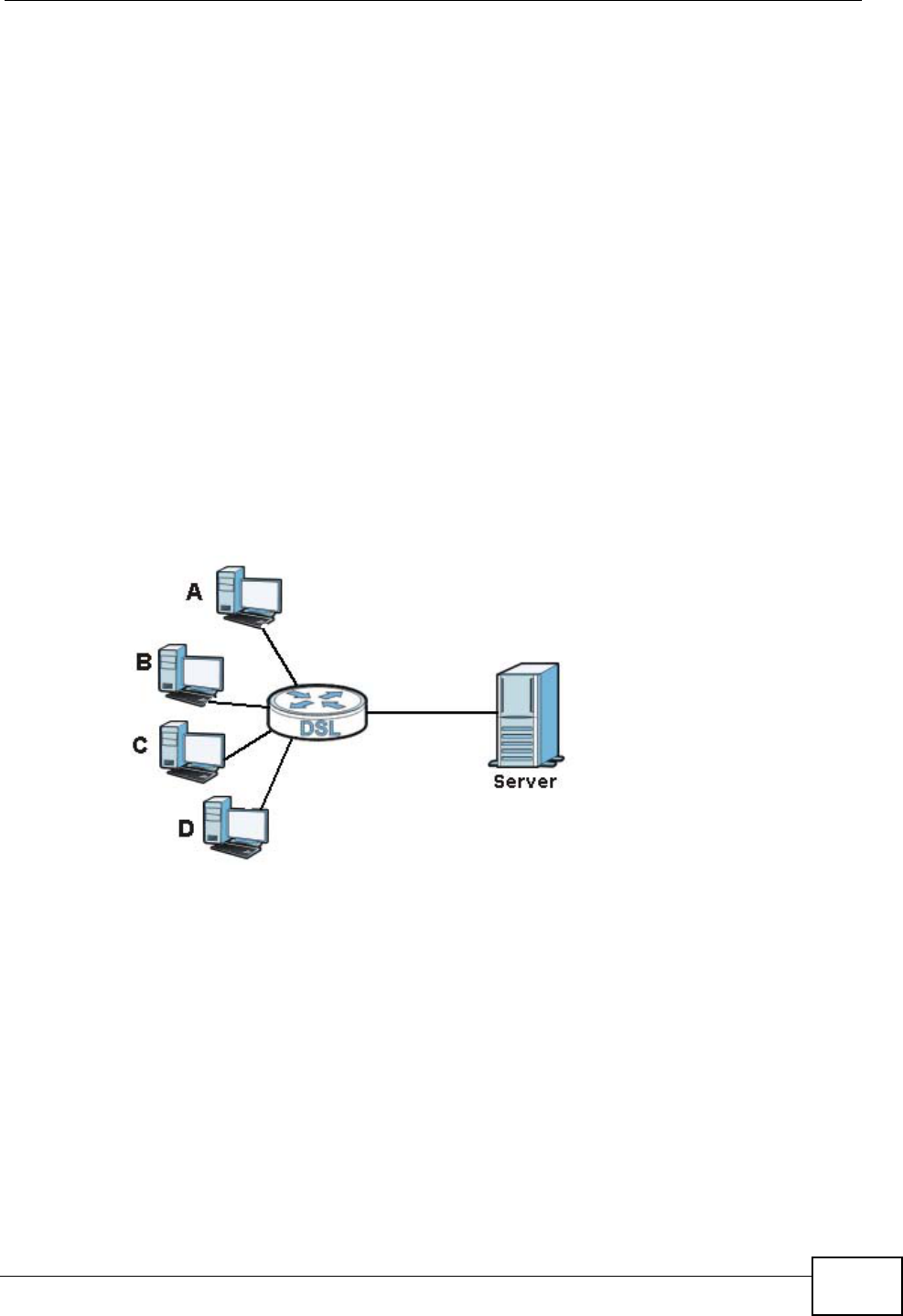
Figure 88 Multicast Example
In the multicast example above, systems A and D comprise one multicast group.
In multicasting, the server only needs to send one data stream and this is
delivered to systems A and D.
IGMP (Internet Group Multicast Protocol) is a network-layer protocol used to
establish membership in a multicast group - it is not used to carry user data. The
NBG4615 supports both IGMP version 1 (IGMP-v1) and IGMP version 2 (IGMP-
v2).
At start up, the NBG4615 queries all directly connected networks to gather group
membership. After that, the NBG4615 periodically updates this information. IP
multicasting can be enabled/disabled on the NBG4615 LAN and/or WAN interfaces
Chapter 16 WAN
NBG4615 User’s Guide
156
in the Web Configurator (LAN; WAN). Select None to disable IP multicasting on
these interfaces.
16.4 Internet Connection
Use this screen to change your NBG4615’s Internet access settings. Click WAN
from the Configuration menu. The screen differs according to the encapsulation
you choose.
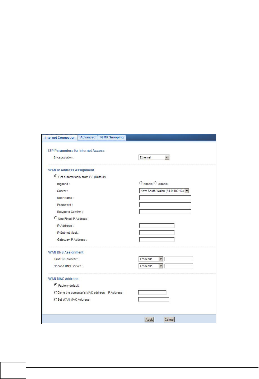
16.4.1 Ethernet Encapsulation
This screen displays when you select Ethernet encapsulation.
Figure 89 Network > WAN > Internet Connection: Ethernet Encapsulation

Chapter 16 WAN
NBG4615 User’s Guide 157
The following table describes the labels in this screen.
Table 54 Network > WAN > Internet Connection: Ethernet Encapsulation
LABEL DESCRIPTION
ISP Parameters for Internet Access
Encapsulation You must choose the Ethernet option when the WAN port is used as a
regular Ethernet.
WAN IP Address Assignment
Get
automatically
from ISP
(Default)
Select this option If your ISP did not assign you a fixed IP address. This
is the default selection.
Bigpond Select Enable if you subscribe to Internet service from BigPond in
Australia. Then configure the fields below with the information
provided.
Server Type the IP address of the BigPond server.
User Name Type the user name given to you by your ISP. You can use
alphanumeric and -_@$./ characters, and it can be up to 31 characters
long.
Password Type the password associated with the user name above. Use up to 64
ASCII characters except [, ] and ?. This field can be blank.
Retype to
Confirm Type your password again for confirmation.
Use Fixed IP
Address Select this option If the ISP assigned a fixed IP address.
IP Address Enter your WAN IP address in this field if you selected Use Fixed IP
Address.
IP Subnet
Mask Enter the IP Subnet Mask in this field.
Gateway IP
Address Enter a Gateway IP Address (if your ISP gave you one) in this field.
WAN DNS Assignment
First DNS Server
Second DNS
Server
Select From ISP if your ISP dynamically assigns DNS server
information (and the NBG4615's WAN IP address). The field to the right
displays the (read-only) DNS server IP address that the ISP assigns.
Select User-Defined if you have the IP address of a DNS server. Enter
the DNS server's IP address in the field to the right. If you chose User-
Defined, but leave the IP address set to 0.0.0.0, User-Defined
changes to None after you click Apply. If you set a second choice to
User-Defined, and enter the same IP address, the second User-
Defined changes to None after you click Apply.
Select None if you do not want to configure DNS servers. If you do not
configure a DNS server, you must know the IP address of a computer in
order to access it.
WAN MAC
Address The MAC address section allows users to configure the WAN port's MAC
address by either using the NBG4615’s MAC address, copying the MAC
address from a computer on your LAN or manually entering a MAC
address.

Chapter 16 WAN
NBG4615 User’s Guide
158
16.4.2 PPPoE Encapsulation
The NBG4615 supports PPPoE (Point-to-Point Protocol over Ethernet). PPPoE is an
IETF standard (RFC 2516) specifying how a personal computer (PC) interacts with
a broadband modem (DSL, cable, wireless, etc.) connection. The PPP over
Ethernet option is for a dial-up connection using PPPoE.
For the service provider, PPPoE offers an access and authentication method that
works with existing access control systems (for example Radius).
One of the benefits of PPPoE is the ability to let you access one of multiple network
services, a function known as dynamic service selection. This enables the service
provider to easily create and offer new IP services for individuals.
Operationally, PPPoE saves significant effort for both you and the ISP or carrier, as
it requires no specific configuration of the broadband modem at the customer site.
By implementing PPPoE directly on the NBG4615 (rather than individual
computers), the computers on the LAN do not need PPPoE software installed,
since the NBG4615 does that part of the task. Furthermore, with NAT, all of the
LANs’ computers will have access.
Factory default Select Factory default to use the factory assigned default MAC
Address.
Clone the
computer’s MAC
address - IP
Address
Select Clone the computer's MAC address - IP Address and enter
the IP address of the computer on the LAN whose MAC you are cloning.
Set WAN MAC
Address Select this option and enter the MAC address you want to use.
Apply Click Apply to save your changes back to the NBG4615.
Cancel Click Cancel to begin configuring this screen afresh.
Table 54 Network > WAN > Internet Connection: Ethernet Encapsulation (continued)
LABEL DESCRIPTION
Chapter 16 WAN
NBG4615 User’s Guide 159
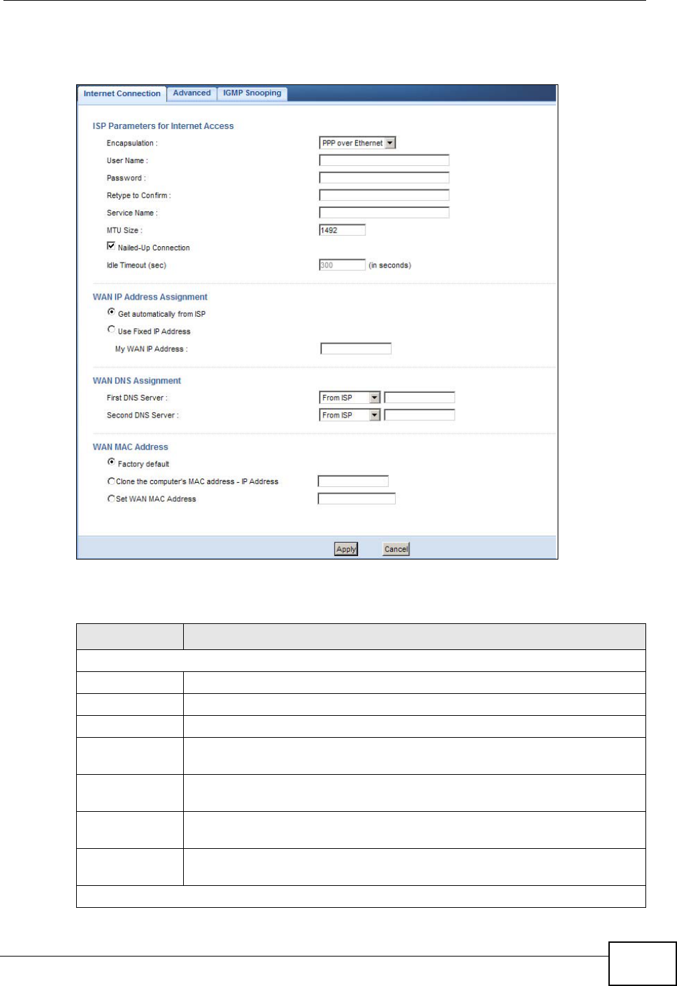
This screen displays when you select PPPoE encapsulation.
Figure 90 Network > WAN > Internet Connection: PPPoE Encapsulation
The following table describes the labels in this screen.
Table 55 Network > WAN > Internet Connection: PPPoE Encapsulation
LABEL DESCRIPTION
ISP Parameters for Internet Access
Encapsulation Select PPP over Ethernet if you connect to your Internet via dial-up.
User Name Type the user name given to you by your ISP.
Password Type the password associated with the user name above.
Retype to
Confirm Type your password again to make sure that you have entered is
correctly.
MTU Size Enter the Maximum Transmission Unit (MTU) or the largest packet size
per frame that your NBG4615 can receive and process.
Nailed-Up
Connection Select Nailed-Up Connection if you do not want the connection to time
out.
Idle Timeout
(sec) This value specifies the time in minutes that elapses before the router
automatically disconnects from the PPPoE server.
WAN IP Address Assignment

Chapter 16 WAN
NBG4615 User’s Guide
160
16.4.3 PPTP Encapsulation
Point-to-Point Tunneling Protocol (PPTP) is a network protocol that enables secure
transfer of data from a remote client to a private server, creating a Virtual Private
Network (VPN) using TCP/IP-based networks.
PPTP supports on-demand, multi-protocol and virtual private networking over
public networks, such as the Internet.
Get
automatically
from ISP
Select this option If your ISP did not assign you a fixed IP address. This
is the default selection.
Use Fixed IP
Address Select this option If the ISP assigned a fixed IP address.
My WAN IP
Address Enter your WAN IP address in this field if you selected Use Fixed IP
Address.
WAN DNS Assignment
First DNS
Server
Second DNS
Server
Select From ISP if your ISP dynamically assigns DNS server information
(and the NBG4615's WAN IP address). The field to the right displays the
(read-only) DNS server IP address that the ISP assigns.
Select User-Defined if you have the IP address of a DNS server. Enter
the DNS server's IP address in the field to the right. If you chose User-
Defined, but leave the IP address set to 0.0.0.0, User-Defined
changes to None after you click Apply. If you set a second choice to
User-Defined, and enter the same IP address, the second User-
Defined changes to None after you click Apply.
Select None if you do not want to configure DNS servers. If you do not
configure a DNS server, you must know the IP address of a computer in
order to access it.
WAN MAC
Address The MAC address section allows users to configure the WAN port's MAC
address by using the NBG4615’s MAC address, copying the MAC address
from a computer on your LAN or manually entering a MAC address.
Factory default Select Factory default to use the factory assigned default MAC
Address.
Clone the
computer’s
MAC address -
IP Address
Select Clone the computer's MAC address - IP Address and enter
the IP address of the computer on the LAN whose MAC you are cloning.
Set WAN MAC
Address Select this option and enter the MAC address you want to use.
Apply Click Apply to save your changes back to the NBG4615.
Cancel Click Cancel to begin configuring this screen afresh.
Table 55 Network > WAN > Internet Connection: PPPoE Encapsulation (continued)
LABEL DESCRIPTION
Chapter 16 WAN
NBG4615 User’s Guide 161
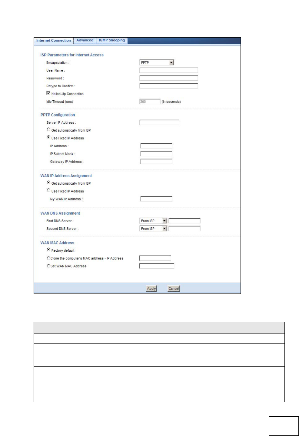
This screen displays when you select PPTP encapsulation.
Figure 91 Network > WAN > Internet Connection: PPTP Encapsulation
The following table describes the labels in this screen.
Table 56 Network > WAN > Internet Connection: PPTP Encapsulation
LABEL DESCRIPTION
ISP Parameters for Internet Access
Connection Type To configure a PPTP client, you must configure the User Name and
Password fields for a PPP connection and the PPTP parameters for
a PPTP connection.
User Name Type the user name given to you by your ISP.
Password Type the password associated with the User Name above.
Retype to Confirm Type your password again to make sure that you have entered is
correctly.

Chapter 16 WAN
NBG4615 User’s Guide
162
Nailed-up
Connection Select Nailed-Up Connection if you do not want the connection to
time out.
Idle Timeout This value specifies the time in minutes that elapses before the
NBG4615 automatically disconnects from the PPTP server.
PPTP Configuration
Server IP Address Type the IP address of the PPTP server.
Get automatically
from ISP Select this option If your ISP did not assign you a fixed IP address.
This is the default selection.
Use Fixed IP
Address Select this option If the ISP assigned a fixed IP address.
IP Address Enter your WAN IP address in this field if you selected Use Fixed IP
Address.
IP Subnet Mask Your NBG4615 will automatically calculate the subnet mask based
on the IP address that you assign. Unless you are implementing
subnetting, use the subnet mask computed by the NBG4615.
Gateway IP
Address Enter a Gateway IP Address (if your ISP gave you one) in this
field.
WAN IP Address Assignment
Get automatically
from ISP Select this to get your WAN IP address from your ISP.
Use Fixed IP
Address Select this option If the ISP assigned a fixed IP address.
My WAN IP
Address Enter your WAN IP address in this field if you selected Use Fixed IP
Address.
WAN DNS Assignment
First DNS Server
Second DNS Server
Select From ISP if your ISP dynamically assigns DNS server
information (and the NBG4615's WAN IP address). The field to the
right displays the (read-only) DNS server IP address that the ISP
assigns.
Select User-Defined if you have the IP address of a DNS server.
Enter the DNS server's IP address in the field to the right. If you
chose User-Defined, but leave the IP address set to 0.0.0.0, User-
Defined changes to None after you click Apply. If you set a second
choice to User-Defined, and enter the same IP address, the
second User-Defined changes to None after you click Apply.
Select None if you do not want to configure DNS servers. If you do
not configure a DNS server, you must know the IP address of a
computer in order to access it.
WAN MAC Address The MAC address section allows users to configure the WAN port's
MAC address by either using the NBG4615’s MAC address, copying
the MAC address from a computer on your LAN or manually entering
a MAC address.
Factory default Select Factory default to use the factory assigned default MAC
Address.
Table 56 Network > WAN > Internet Connection: PPTP Encapsulation (continued)
LABEL DESCRIPTION

Chapter 16 WAN
NBG4615 User’s Guide 163
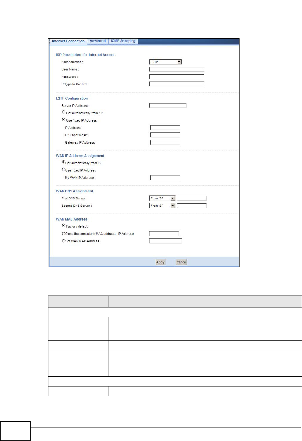
16.4.4 L2TP Encapsulation
The Layer 2 Tunneling Protocol (L2TP) works at layer 2 (the data link layer) to
tunnel network traffic between two peer devices over another network (like the
Internet).
Clone the
computer’s MAC
address - IP
Address
Select Clone the computer's MAC address - IP Address and
enter the IP address of the computer on the LAN whose MAC you
are cloning.
Set WAN MAC
Address Select this option and enter the MAC address you want to use.
Apply Click Apply to save your changes back to the NBG4615.
Cancel Click Cancel to begin configuring this screen afresh.
Table 56 Network > WAN > Internet Connection: PPTP Encapsulation (continued)
LABEL DESCRIPTION
Chapter 16 WAN
NBG4615 User’s Guide
164
This screen displays when you select L2TP encapsulation.
Figure 92 Network > WAN > Internet Connection: L2TP Encapsulation
The following table describes the labels in this screen.
Table 57 Network > WAN > Internet Connection: L2TP Encapsulation
LABEL DESCRIPTION
ISP Parameters for Internet Access
Connection Type To configure a L2TP client, you must configure the User Name and
Password fields for a layer-2 connection and the L2TP parameters
for an L2TP connection.
User Name Type the user name given to you by your ISP.
Password Type the password associated with the User Name above.
Retype to Confirm Type your password again to make sure that you have entered is
correctly.
L2TP Configuration
Server IP Address Type the IP address of the L2TP server.

Chapter 16 WAN
NBG4615 User’s Guide 165
Get automatically
from ISP Select this option If your ISP did not assign you a fixed IP address.
This is the default selection.
Use Fixed IP
Address Select this option If the ISP assigned a fixed IP address.
IP Address Enter your WAN IP address in this field if you selected Use Fixed IP
Address.
IP Subnet Mask Your NBG4615 will automatically calculate the subnet mask based
on the IP address that you assign. Unless you are implementing
subnetting, use the subnet mask computed by the NBG4615.
Gateway IP
Address Enter a Gateway IP Address (if your ISP gave you one) in this
field.
WAN IP Address Assignment
Get automatically
from ISP Select this to get your WAN IP address from your ISP.
Use Fixed IP
Address Select this option If the ISP assigned a fixed IP address.
My WAN IP
Address Enter your WAN IP address in this field if you selected Use Fixed IP
Address.
WAN DNS Assignment
First DNS Server
Second DNS Server
Select From ISP if your ISP dynamically assigns DNS server
information (and the NBG4615's WAN IP address). The field to the
right displays the (read-only) DNS server IP address that the ISP
assigns.
Select User-Defined if you have the IP address of a DNS server.
Enter the DNS server's IP address in the field to the right. If you
chose User-Defined, but leave the IP address set to 0.0.0.0, User-
Defined changes to None after you click Apply. If you set a second
choice to User-Defined, and enter the same IP address, the
second User-Defined changes to None after you click Apply.
Select None if you do not want to configure DNS servers. If you do
not configure a DNS server, you must know the IP address of a
computer in order to access it.
WAN MAC Address The MAC address section allows users to configure the WAN port's
MAC address by either using the NBG4615’s MAC address, copying
the MAC address from a computer on your LAN or manually entering
a MAC address.
Factory default Select Factory default to use the factory assigned default MAC
Address.
Clone the
computer’s MAC
address - IP
Address
Select Clone the computer's MAC address - IP Address and
enter the IP address of the computer on the LAN whose MAC you
are cloning.
Set WAN MAC
Address Select this option and enter the MAC address you want to use.
Apply Click Apply to save your changes back to the NBG4615.
Reset Click Reset to begin configuring this screen afresh.
Table 57 Network > WAN > Internet Connection: L2TP Encapsulation (continued)
LABEL DESCRIPTION
Chapter 16 WAN
NBG4615 User’s Guide
166
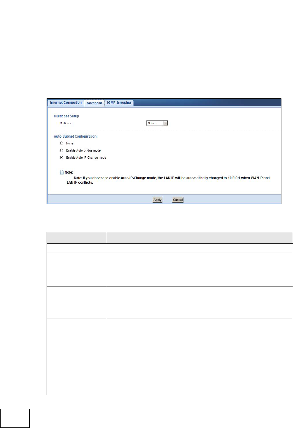
16.5 Advanced WAN Screen
Use this screen to enable Multicast and enable Auto-bridge.
Note: The categories shown in this screen are independent of each other.
To change your NBG4615’s advanced WAN settings, click Network > WAN >
Advanced. The screen appears as shown.
Figure 93 Network > WAN > Advanced
The following table describes the labels in this screen.
Table 58 Network > WAN > Advanced
LABEL DESCRIPTION
Multicast Setup
Multicast Select IGMPv1/v2 to enable multicasting. This applies to traffic
routed from the WAN to the LAN.
Select None to disable this feature. This may cause incoming traffic
to be dropped or sent to all connected network devices.
Auto-Subnet Configuration
None Select this option to have the NBG4615 do nothing when it gets a
WAN IP address in the range of 192.168.x.y (where x and y are
from zero to nine) or in the same subnet as the LAN IP address.
Enable Auto-bridge
mode Select this option to have the NBG4615 switch to bridge mode
automatically when the NBG4615 gets a WAN IP address in the
range of 192.168.x.y (where x and y are from zero to nine) no
matter what the LAN IP address is.
Enable Auto-IP-
Change mode Select this option to have the NBG4615 change its LAN IP address
to 10.0.0.1 or 192.168.1.1 accordingly when the NBG4615 gets a
dynamic WAN IP address in the same subnet as the LAN IP address
192.168.1.1 or 10.0.0.1.
The NAT, DHCP server and firewall functions on the NBG4615 are
still available in this mode.
Chapter 16 WAN
NBG4615 User’s Guide 167
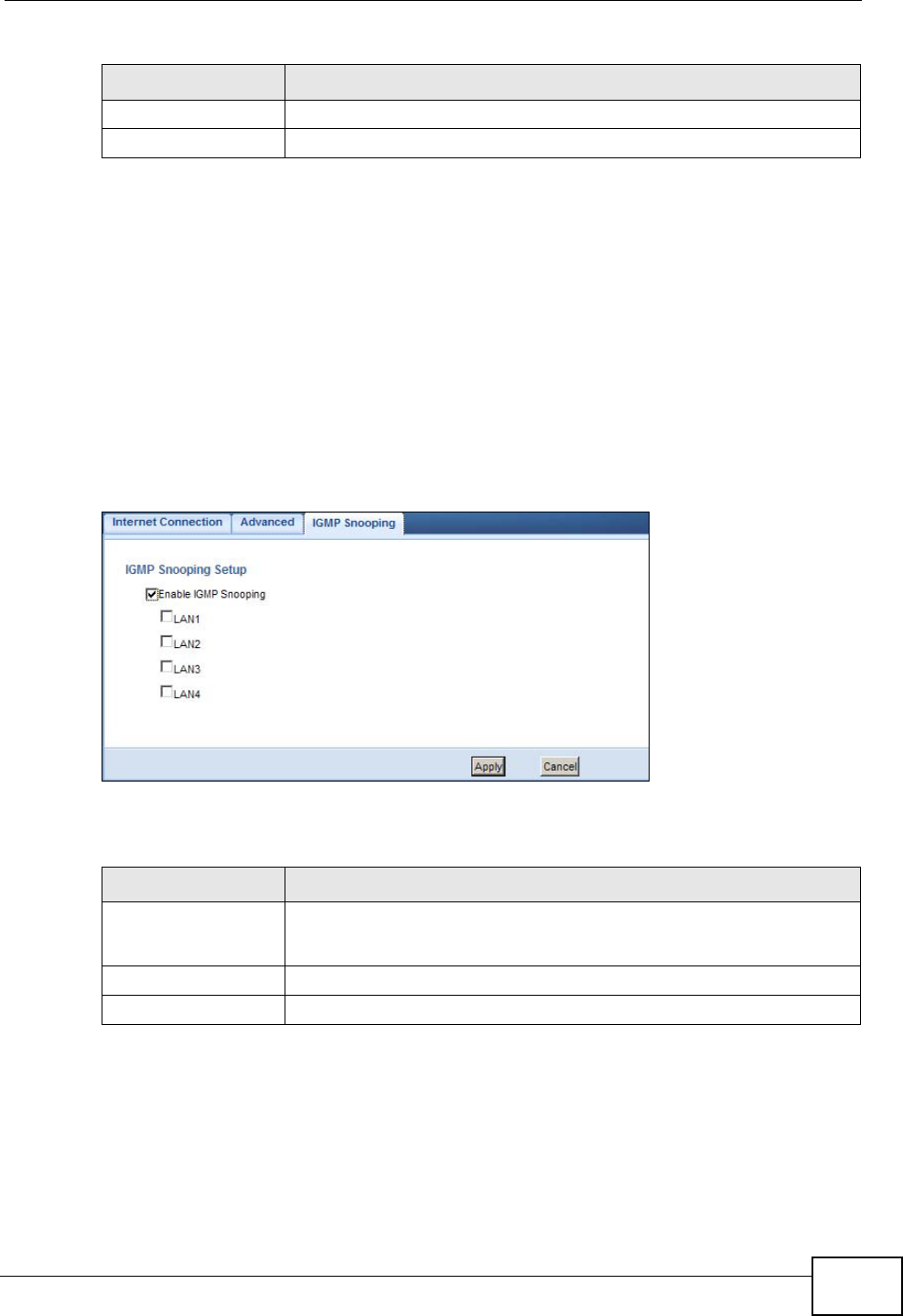
16.6 IGMP Snooping Screen
Use this screen to enable IGMP snooping if you have LAN users that subscribe to
multicast services.
IGMP (Internet Group Multicast Protocol) is a network-layer protocol used to
establish membership in a multicast group - it is not used to carry user data.
Click Network > WAN > IGMP Snooping. The screen appears as shown.
Figure 94 Network > WAN > IGMP Snooping
The following table describes the labels in this screen.
Apply Click Apply to save your changes back to the NBG4615.
Cancel Click Cancel to begin configuring this screen afresh.
Table 58 Network > WAN > Advanced (continued)
LABEL DESCRIPTION
Table 59 Network > WAN > IGMP Snooping
LABEL DESCRIPTION
Enable IGMP
Snooping Select this option to have the NBG4615 use IGMP snooping.
Check the LAN port/s to which IGMP snooping applies.
Apply Click Apply to save your changes back to the NBG4615.
Cancel Click Cancel to begin configuring this screen afresh.

Chapter 16 WAN
NBG4615 User’s Guide
168
NBG4615 User’s Guide 169
CHAPTER 17
LAN
17.1 Overview
This chapter describes how to configure LAN settings.
A Local Area Network (LAN) is a shared communication system to which many
computers are attached. A LAN is a computer network limited to the immediate
area, usually the same building or floor of a building. The LAN screens can help
you configure a LAN DHCP server, manage IP addresses, and partition your
physical network into logical networks.
Figure 95 LAN Example
The LAN screens can help you manage IP addresses.
17.2 What You Can Do
•Use the IP screen to change the IP address for your (Section 17.4 on page
171).
•Use the IP Alias screen to have the NBG4615 apply IP alias to create LAN
subnets (Section 17.5 on page 172).
Chapter 17 LAN
NBG4615 User’s Guide
170
17.3 What You Need To Know
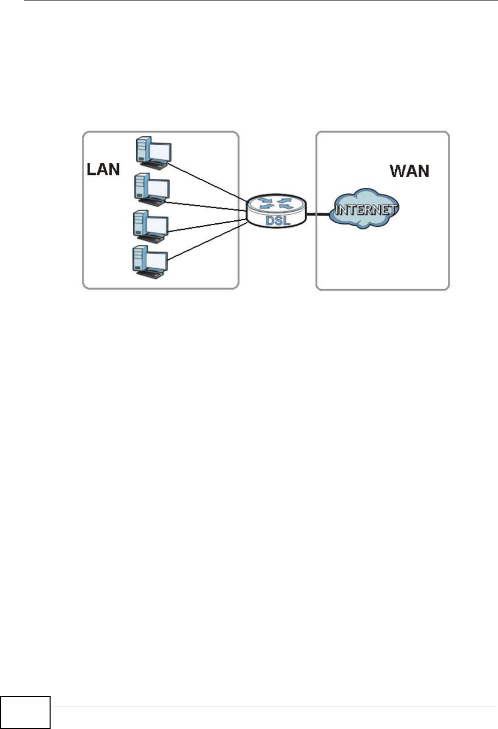
The actual physical connection determines whether the NBG4615 ports are LAN or
WAN ports. There are two separate IP networks, one inside the LAN network and
the other outside the WAN network as shown next.
Figure 96 LAN and WAN IP Addresses
The LAN parameters of the NBG4615 are preset in the factory with the following
values:
• IP address of 192.168.1.1 with subnet mask of 255.255.255.0 (24 bits)
• DHCP server enabled with 32 client IP addresses starting from 192.168.1.33.
These parameters should work for the majority of installations. If your ISP gives
you explicit DNS server address(es), read the embedded Web Configurator help
regarding what fields need to be configured.
17.3.1 IP Pool Setup
The NBG4615 is pre-configured with a pool of 32 IP addresses starting from
192.168.1.33 to 192.168.1.64. This configuration leaves 31 IP addresses
(excluding the NBG4615 itself) in the lower range (192.168.1.2 to 192.168.1.32)
for other server computers, for instance, servers for mail, FTP, TFTP, web, etc.,
that you may have.
17.3.2 LAN TCP/IP
The NBG4615 has built-in DHCP server capability that assigns IP addresses and
DNS servers to systems that support DHCP client capability.
Chapter 17 LAN
NBG4615 User’s Guide 171
17.3.3 IP Alias
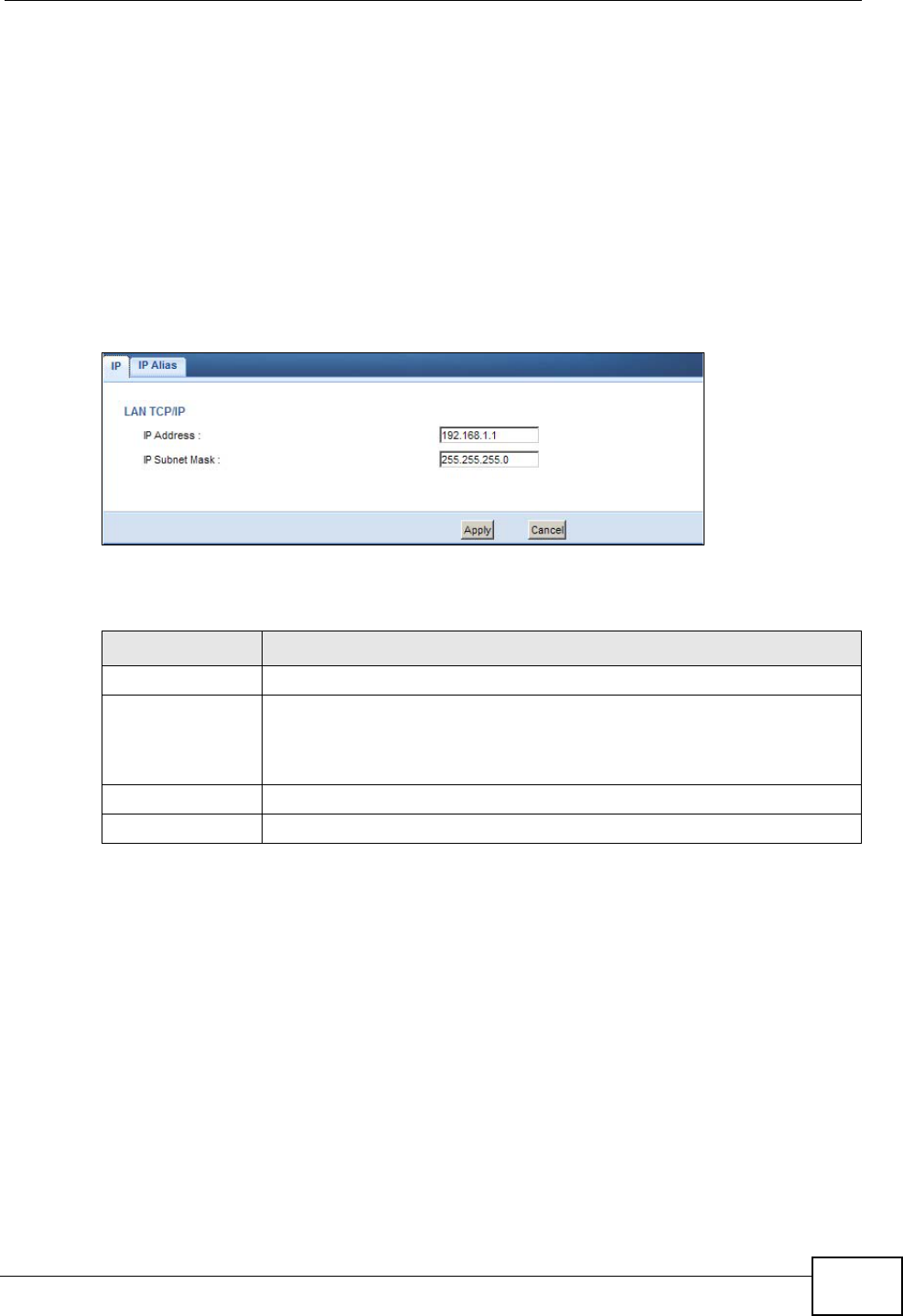
17.4 LAN IP Screen
Use this screen to change the IP address for your NBG4615. Click Network >
LAN > IP.
Figure 97 Network > LAN > IP
The following table describes the labels in this screen.
Table 60 Network > LAN > IP
LABEL DESCRIPTION
IP Address Type the IP address of your NBG4615 in dotted decimal notation.
IP Subnet Mask The subnet mask specifies the network number portion of an IP
address. Your NBG4615 will automatically calculate the subnet mask
based on the IP address that you assign. Unless you are implementing
subnetting, use the subnet mask computed by the NBG4615.
Apply Click Apply to save your changes back to the NBG4615.
Cancel Click Cancel to begin configuring this screen afresh.
Chapter 17 LAN
NBG4615 User’s Guide
172
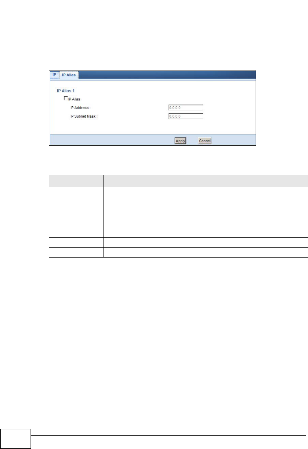
17.5 IP Alias Screen
Use this screen to have the NBG4615 apply IP alias to create LAN subnets. Click
LAN > IP Alias.
Figure 98 Network > LAN > IP Alias
The following table describes the labels in this screen.
Table 61 Network > LAN > IP Alias
LABEL DESCRIPTION
IP Alias Check this to enable IP alias.
IP Address Type the IP alias address of your NBG4615 in dotted decimal notation.
IP Subnet Mask The subnet mask specifies the network number portion of an IP
address. Your NBG4615 will automatically calculate the subnet mask
based on the IP address that you assign. Unless you are implementing
subnetting, use the subnet mask computed by the NBG4615.
Apply Click Apply to save your changes back to the NBG4615.
Cancel Click Cancel to begin configuring this screen afresh.

NBG4615 User’s Guide 173
CHAPTER 18
DHCP Server
18.1 Overview
DHCP (Dynamic Host Configuration Protocol, RFC 2131 and RFC 2132) allows
individual clients to obtain TCP/IP configuration at start-up from a server. You can
configure the NBG4615’s LAN as a DHCP server or disable it. When configured as a
server, the NBG4615 provides the TCP/IP configuration for the clients. If DHCP
service is disabled, you must have another DHCP server on your LAN, or else the
computer must be manually configured.
18.1.1 What You Can Do
•Use the General screen to enable the DHCP server (Section 18.2 on page 174).
•Use the Advanced screen to assign IP addresses on the LAN to specific
individual computers based on their MAC Addresses (Section 18.3 on page 175).
18.1.2 What You Need To Know
The following terms and concepts may help as you read through this chapter.
MAC Addresses
Every Ethernet device has a unique MAC (Media Access Control) address. The MAC
address is assigned at the factory and consists of six pairs of hexadecimal
characters, for example, 00:A0:C5:00:00:02. Find out the MAC addresses of your
network devices if you intend to add them to the DHCP Client List screen.
Chapter 18 DHCP Server
NBG4615 User’s Guide
174
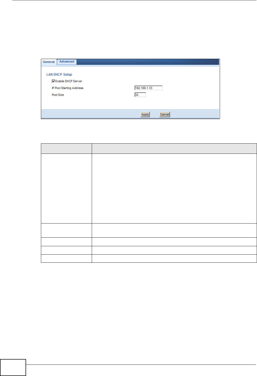
18.2 General
Use this screen to enable the DHCP server. Click Network > DHCP Server. The
following screen displays.
Figure 99 Network > DHCP Server > General
The following table describes the labels in this screen.
Table 62 Network > DHCP Server > General
LABEL DESCRIPTION
Enable DHCP
Server Select the checkbox to enable DHCP for LAN.
DHCP (Dynamic Host Configuration Protocol, RFC 2131 and RFC
2132) allows individual clients (computers) to obtain TCP/IP
configuration at startup from a server. Leave the Enable DHCP
Server check box selected unless your ISP instructs you to do
otherwise. Clear it to disable the NBG4615 acting as a DHCP server.
When configured as a server, the NBG4615 provides TCP/IP
configuration for the clients. If not, DHCP service is disabled and
you must have another DHCP server on your LAN, or else the
computers must be manually configured. When set as a server, fill in
the following four fields.
IP Pool Starting
Address This field specifies the first of the contiguous addresses in the IP
address pool for LAN.
Pool Size This field specifies the size, or count of the IP address pool for LAN.
Apply Click Apply to save your changes back to the NBG4615.
Cancel Click Cancel to begin configuring this screen afresh.
Chapter 18 DHCP Server
NBG4615 User’s Guide 175
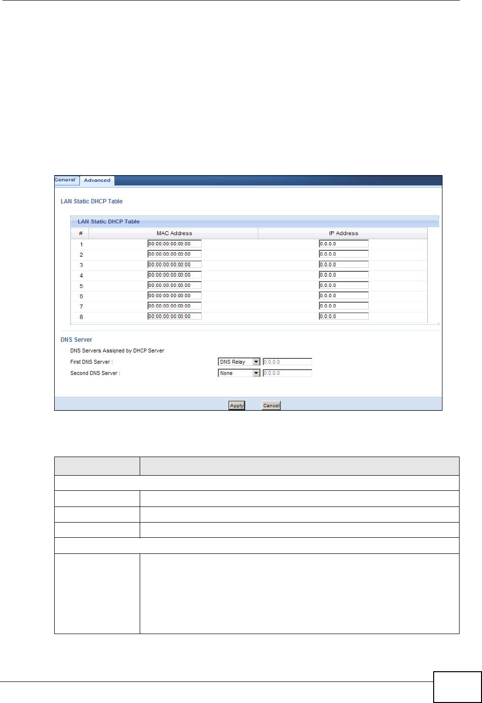
18.3 Advanced
This screen allows you to assign IP addresses on the LAN to specific individual
computers based on their MAC addresses. You can also use this screen to
configure the DNS server information that the NBG4615 sends to the DHCP
clients.
To change your NBG4615’s static DHCP settings, click Network > DHCP Server
> Advanced. The following screen displays.
Figure 100 Network > DHCP Server > Advanced
The following table describes the labels in this screen.
Table 63 Network > DHCP Server > Advanced
LABEL DESCRIPTION
LAN Static DHCP Table
# This is the index number of the static IP table entry (row).
MAC Address Type the MAC address (with colons) of a computer on your LAN.
IP Address Type the LAN IP address of a computer on your LAN.
DNS Server
DNS Servers
Assigned by
DHCP Server
The NBG4615 passes a DNS (Domain Name System) server IP
address (in the order you specify here) to the DHCP clients. The
NBG4615 only passes this information to the LAN DHCP clients when
you select the Enable DHCP Server check box. When you clear the
Enable DHCP Server check box, DHCP service is disabled and you
must have another DHCP sever on your LAN, or else the computers
must have their DNS server addresses manually configured.

Chapter 18 DHCP Server
NBG4615 User’s Guide
176
First DNS Server
Second DNS
Server
Select From ISP if your ISP dynamically assigns DNS server
information (and the NBG4615's WAN IP address). The field to the
right displays the (read-only) DNS server IP address that the ISP
assigns.
Select User-Defined if you have the IP address of a DNS server.
Enter the DNS server's IP address in the field to the right. If you chose
User-Defined, but leave the IP address set to 0.0.0.0, User-Defined
changes to None after you click Apply. If you set a second choice to
User-Defined, and enter the same IP address, the second User-
Defined changes to None after you click Apply.
Select DNS Relay to have the NBG4615 act as a DNS proxy. The
NBG4615's LAN IP address displays in the field to the right (read-
only). The NBG4615 tells the DHCP clients on the LAN that the
NBG4615 itself is the DNS server. When a computer on the LAN sends
a DNS query to the NBG4615, the NBG4615 forwards the query to the
NBG4615's system DNS server (configured in the WAN > Internet
Connection screen) and relays the response back to the computer.
You can only select DNS Relay for one of the three servers; if you
select DNS Relay for a second or third DNS server, that choice
changes to None after you click Apply.
Select None if you do not want to configure DNS servers. If you do
not configure a DNS server, you must know the IP address of a
computer in order to access it.
Apply Click Apply to save your changes back to the NBG4615.
Cancel Click Cancel to begin configuring this screen afresh.
Table 63 Network > DHCP Server > Advanced (continued)
LABEL DESCRIPTION
NBG4615 User’s Guide 177
CHAPTER 19
NAT
19.1 Overview
NAT (Network Address Translation - NAT, RFC 1631) is the translation of the IP
address of a host in a packet. For example, the source address of an outgoing
packet, used within one network is changed to a different IP address known within
another network.
The figure below is a simple illustration of a NAT network. You want to assign ports
21-25 to one FTP, Telnet and SMTP server (A in the example), port 80 to another
(B in the example) and assign a default server IP address of 192.168.1.35 to a
third (C in the example).
You assign the LAN IP addresses to the devices (A to D) connected to your
NBG4615. The ISP assigns the WAN IP address. The NAT network appears as a
single host on the Internet. All traffic coming from A to D going out to the Internet
use the IP address of the NBG4615, which is 192.168.1.1.
Figure 101 NAT Example
This chapter discusses how to configure NAT on the NBG4615.
A: 192.168.1.33
B: 192.168.1.34
C: 192.168.1.35
IP address
192.168.1.1
WANLAN
assigned by ISP
FTP, Telnet, SNMP
Port 80
Ports 21 to 25

Chapter 19 NAT
NBG4615 User’s Guide
178
Note: You must create a firewall rule in addition to setting up NAT, to allow traffic from
the WAN to be forwarded through the NBG4615.
19.1.1 What You Can Do
•Use the General screen to enable NAT and set a default server (Section 19.2 on
page 180).
•Use the Application screen to change your NBG4615’s port forwarding settings
(Section 19.3 on page 181).
•Use the Advanced screen to change your NBG4615’s trigger port settings
(Section 19.5.3 on page 185).
19.1.2 What You Need To Know
The following terms and concepts may help as you read through this chapter.
Inside/Outside
This denotes where a host is located relative to the NBG4615, for example, the
computers of your subscribers are the inside hosts, while the web servers on the
Internet are the outside hosts.
Global/Local
This denotes the IP address of a host in a packet as the packet traverses a router,
for example, the local address refers to the IP address of a host when the packet
is in the local network, while the global address refers to the IP address of the
host when the same packet is traveling in the WAN side.
Note: Inside/outside refers to the location of a host, while global/local refers to the IP
address of a host used in a packet.
An inside local address (ILA) is the IP address of an inside host in a packet when
the packet is still in the local network, while an inside global address (IGA) is the
IP address of the same inside host when the packet is on the WAN side. The
following table summarizes this information.
Table 64 NAT Definitions
ITEM DESCRIPTION
Inside This refers to the host on the LAN.
Outside This refers to the host on the WAN.

Chapter 19 NAT
NBG4615 User’s Guide 179
Note: NAT never changes the IP address (either local or global) of an outside host.
What NAT Does
In the simplest form, NAT changes the source IP address in a packet received from
a subscriber (the inside local address) to another (the inside global address)
before forwarding the packet to the WAN side. When the response comes back,
NAT translates the destination address (the inside global address) back to the
inside local address before forwarding it to the original inside host. Note that the
IP address (either local or global) of an outside host is never changed.
The global IP addresses for the inside hosts can be either static or dynamically
assigned by the ISP. In addition, you can designate servers, for example, a web
server and a telnet server, on your local network and make them accessible to the
outside world. If you do not define any servers , NAT offers the additional benefit
of firewall protection. With no servers defined, your NBG4615 filters out all
incoming inquiries, thus preventing intruders from probing your network. For
more information on IP address translation, refer to RFC 1631, The IP Network
Address Translator (NAT).
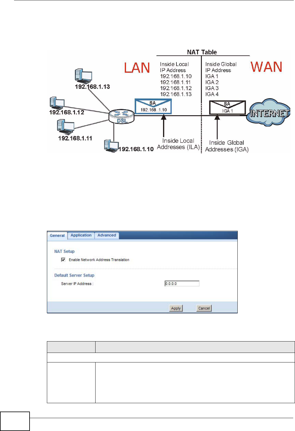
How NAT Works
Each packet has two addresses – a source address and a destination address. For
outgoing packets, the ILA (Inside Local Address) is the source address on the LAN,
and the IGA (Inside Global Address) is the source address on the WAN. For
incoming packets, the ILA is the destination address on the LAN, and the IGA is
the destination address on the WAN. NAT maps private (local) IP addresses to
globally unique ones required for communication with hosts on other networks. It
replaces the original IP source address in each packet and then forwards it to the
Internet. The NBG4615 keeps track of the original addresses and port numbers so
Local This refers to the packet address (source
or destination) as the packet travels on
the LAN.
Global This refers to the packet address (source
or destination) as the packet travels on
the WAN.
Table 64 NAT Definitions (continued)
ITEM DESCRIPTION
Chapter 19 NAT
NBG4615 User’s Guide
180
incoming reply packets can have their original values restored. The following
figure illustrates this.
Figure 102 How NAT Works
19.2 General
Use this screen to enable NAT and set a default server. Click Network > NAT to
open the General screen.
Figure 103 Network > NAT > General
The following table describes the labels in this screen.
Table 65 Network > NAT > General
LABEL DESCRIPTION
NAT Setup
Enable Network
Address
Translation
Network Address Translation (NAT) allows the translation of an Internet
protocol address used within one network (for example a private IP
address used in a local network) to a different IP address known within
another network (for example a public IP address used on the Internet).
Select the check box to enable NAT.
Chapter 19 NAT
NBG4615 User’s Guide 181
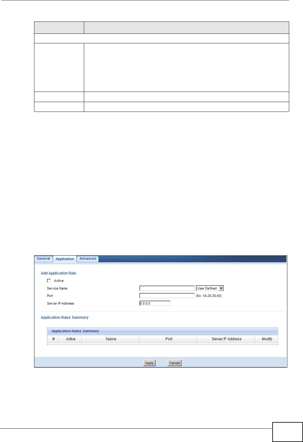
19.3 Application
Port forwarding allows you to define the local servers to which the incoming
services will be forwarded. To change your NBG4615’s port forwarding settings,
click Network > NAT > Application. The screen appears as shown.
Note: If you do not assign a Default Server IP address in the NAT > General screen,
the NBG4615 discards all packets received for ports that are not specified in
this screen or remote management.
Refer to Appendix F on page 321 for port numbers commonly used for particular
services.
Figure 104 Network > NAT > Application
Default Server Setup
Server IP
Address In addition to the servers for specified services, NAT supports a default
server. A default server receives packets from ports that are not
specified in the Application screen.
If you do not assign a Default Server IP address, the NBG4615
discards all packets received for ports that are not specified in the
Application screen or remote management.
Apply Click Apply to save your changes back to the NBG4615.
Cancel Click Cancel to begin configuring this screen afresh.
Table 65 Network > NAT > General (continued)
LABEL DESCRIPTION

Chapter 19 NAT
NBG4615 User’s Guide
182
The following table describes the labels in this screen.
Table 66 Network > NAT > Application
LABEL DESCRIPTION
Add Application Rule
Active Select the check box to enable this rule and the requested service can
be forwarded to the host with a specified internal IP address.
Clear the checkbox to disallow forwarding of these ports to an inside
server without having to delete the entry.
Service Name Type a name (of up to 31 printable characters) to identify this rule in
the first field next to Service Name. Otherwise, select a predefined
service in the second field next to Service Name. The predefined
service name and port number(s) will display in the Service Name and
Port fields.
Port Enter the start and end port(s) to be forwarded.
Server IP
Address Type the inside IP address of the server that receives packets from the
port(s) specified in the Port field.
Application Rules Summary
#This is the number of an individual port forwarding server entry.
Active This icon is turned on when the rule is enabled.
Name This field displays a name to identify this rule.
Port This field displays the port number(s).
Server IP
Address This field displays the inside IP address of the server.
Modify Click the Edit icon to display and modify an existing rule setting in the
fields under Add Application Rule.
Click the Remove icon to delete a rule.
Apply Click Apply to save your changes back to the NBG4615.
Cancel Click Cancel to begin configuring this screen afresh.
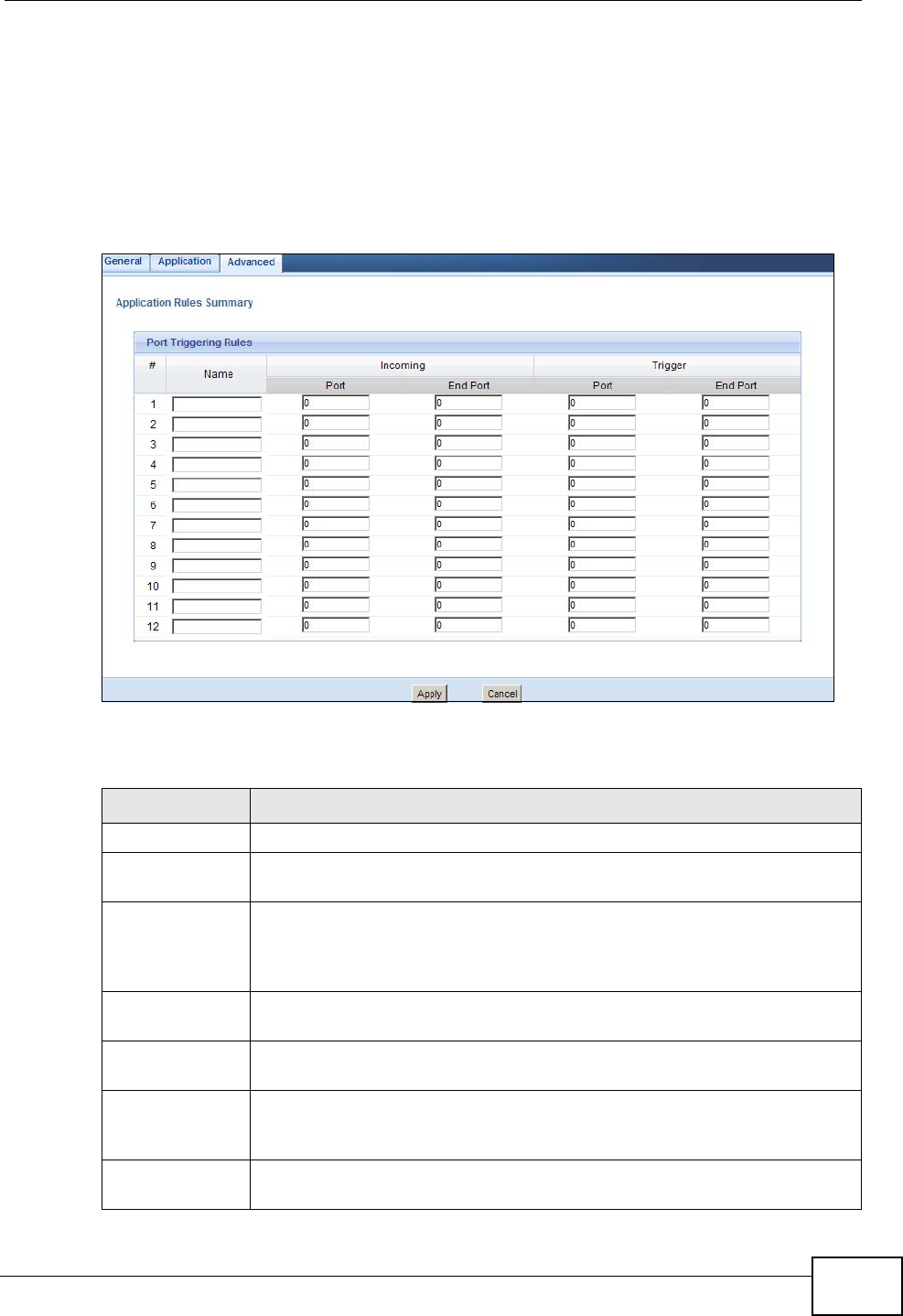
Chapter 19 NAT
NBG4615 User’s Guide 183
19.4 Advanced
To change your NBG4615’s trigger port settings, click Network > NAT >
Advanced. The screen appears as shown.
Note: Only one LAN computer can use a trigger port (range) at a time.
Figure 105 Network > NAT > Advanced
The following table describes the labels in this screen.
Table 67 Network > NAT > Advanced
LABEL DESCRIPTION
#This is the rule index number (read-only).
Name Type a unique name (up to 15 characters) for identification purposes. All
characters are permitted - including spaces.
Incoming Incoming is a port (or a range of ports) that a server on the WAN uses
when it sends out a particular service. The NBG4615 forwards the traffic
with this port (or range of ports) to the client computer on the LAN that
requested the service.
Port Type a port number or the starting port number in a range of port
numbers.
End Port Type a port number or the ending port number in a range of port
numbers.
Trigger The trigger port is a port (or a range of ports) that causes (or triggers)
the NBG4615 to record the IP address of the LAN computer that sent
the traffic to a server on the WAN.
Port Type a port number or the starting port number in a range of port
numbers.

Chapter 19 NAT
NBG4615 User’s Guide
184
19.5 Technical Reference
The following section contains additional technical information about the NBG4615
features described in this chapter.
19.5.1 NATPort Forwarding: Services and Port Numbers
A port forwarding set is a list of inside (behind NAT on the LAN) servers, for
example, web or FTP, that you can make accessible to the outside world even
though NAT makes your whole inside network appear as a single machine to the
outside world.
Use the Application screen to forward incoming service requests to the server(s)
on your local network. You may enter a single port number or a range of port
numbers to be forwarded, and the local IP address of the desired server. The port
number identifies a service; for example, web service is on port 80 and FTP on
port 21. In some cases, such as for unknown services or where one server can
support more than one service (for example both FTP and web service), it might
be better to specify a range of port numbers.
In addition to the servers for specified services, NAT supports a default server. A
service request that does not have a server explicitly designated for it is forwarded
to the default server. If the default is not defined, the service request is simply
discarded.
Note: Many residential broadband ISP accounts do not allow you to run any server
processes (such as a Web or FTP server) from your location. Your ISP may
periodically check for servers and may suspend your account if it discovers any
active services at your location. If you are unsure, refer to your ISP.
19.5.2 NAT Port Forwarding Example
Let's say you want to assign ports 21-25 to one FTP, Telnet and SMTP server (A in
the example), port 80 to another (B in the example) and assign a default server IP
address of 192.168.1.35 to a third (C in the example). You assign the LAN IP
End Port Type a port number or the ending port number in a range of port
numbers.
Apply Click Apply to save your changes back to the NBG4615.
Cancel Click Cancel to begin configuring this screen afresh.
Table 67 Network > NAT > Advanced (continued)
LABEL DESCRIPTION
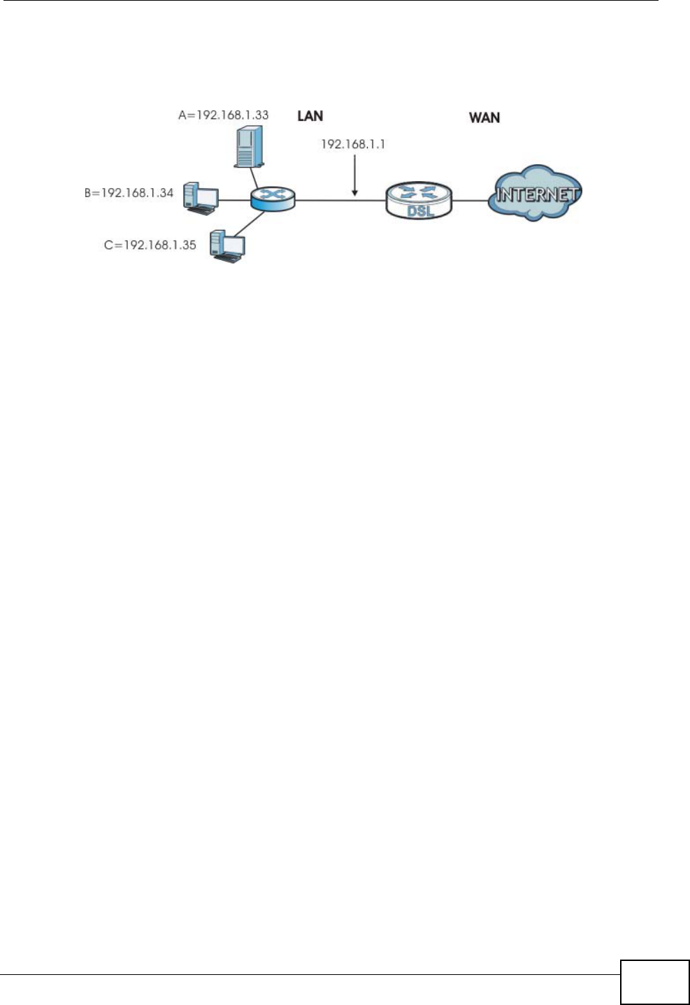
Chapter 19 NAT
NBG4615 User’s Guide 185
addresses and the ISP assigns the WAN IP address. The NAT network appears as a
single host on the Internet.
Figure 106 Multiple Servers Behind NAT Example
19.5.3 Trigger Port Forwarding
Some services use a dedicated range of ports on the client side and a dedicated
range of ports on the server side. With regular port forwarding you set a
forwarding port in NAT to forward a service (coming in from the server on the
WAN) to the IP address of a computer on the client side (LAN). The problem is
that port forwarding only forwards a service to a single LAN IP address. In order to
use the same service on a different LAN computer, you have to manually replace
the LAN computer's IP address in the forwarding port with another LAN
computer's IP address.
Trigger port forwarding solves this problem by allowing computers on the LAN to
dynamically take turns using the service. The NBG4615 records the IP address of
a LAN computer that sends traffic to the WAN to request a service with a specific
port number and protocol (a "trigger" port). When the NBG4615's WAN port
receives a response with a specific port number and protocol ("incoming" port),
the NBG4615 forwards the traffic to the LAN IP address of the computer that sent
the request. After that computer’s connection for that service closes, another
computer on the LAN can use the service in the same manner. This way you do not
need to configure a new IP address each time you want a different LAN computer
to use the application.
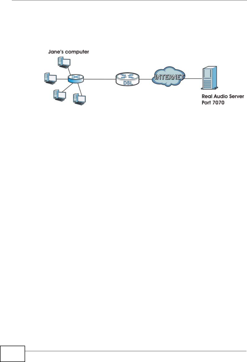
Chapter 19 NAT
NBG4615 User’s Guide
186
19.5.4 Trigger Port Forwarding Example
The following is an example of trigger port forwarding.
Figure 107 Trigger Port Forwarding Process: Example
1Jane requests a file from the Real Audio server (port 7070).
2Port 7070 is a “trigger” port and causes the NBG4615 to record Jane’s computer IP
address. The NBG4615 associates Jane's computer IP address with the "incoming"
port range of 6970-7170.
3The Real Audio server responds using a port number ranging between 6970-7170.
4The NBG4615 forwards the traffic to Jane’s computer IP address.
5Only Jane can connect to the Real Audio server until the connection is closed or
times out. The NBG4615 times out in three minutes with UDP (User Datagram
Protocol), or two hours with TCP/IP (Transfer Control Protocol/Internet Protocol).
19.5.5 Two Points To Remember About Trigger Ports
1Trigger events only happen on data that is going coming from inside the NBG4615
and going to the outside.
2If an application needs a continuous data stream, that port (range) will be tied up
so that another computer on the LAN can’t trigger it.

NBG4615 User’s Guide 187
CHAPTER 20
DDNS
20.1 Overview
DDNS services let you use a domain name with a dynamic IP address.
20.1.1 What You Need To Know
The following terms and concepts may help as you read through this chapter.
What is DDNS?
DDNS, or Dynamic DNS, allows you to update your current dynamic IP address
with one or many dynamic DNS services so that anyone can contact you (in
NetMeeting, CU-SeeMe, etc.). You can also access your FTP server or Web site on
your own computer using a domain name (for instance myhost.dhs.org, where
myhost is a name of your choice) that will never change instead of using an IP
address that changes each time you reconnect. Your friends or relatives will
always be able to call you even if they don't know your IP address.
DynDNS Wildcard
Enabling the wildcard feature for your host causes *.yourhost.dyndns.org to be
aliased to the same IP address as yourhost.dyndns.org. This feature is useful if
you want to be able to use, for example, www.yourhost.dyndns.org and still reach
your hostname.
Note: If you have a private WAN IP address, then you cannot use Dynamic DNS. You
must have a public WAN IP address.
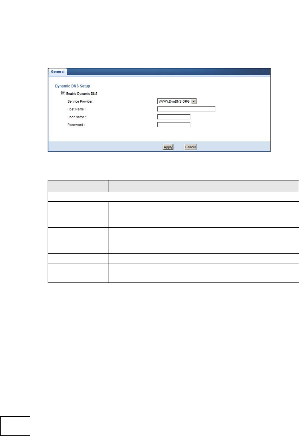
Chapter 20 DDNS
NBG4615 User’s Guide
188
20.2 General
To change your NBG4615’s DDNS, click Network > DDNS. The screen appears as
shown.
Figure 108 Dynamic DNS
The following table describes the labels in this screen.
Table 68 Dynamic DNS
LABEL DESCRIPTION
Dynamic DNS Setup
Enable Dynamic
DNS Select this check box to use dynamic DNS.
Service Provider Select the name of your Dynamic DNS service provider.
Host Name Enter a host names in the field provided. You can specify up to two
host names in the field separated by a comma (",").
User Name Enter your user name.
Password Enter the password assigned to you.
Apply Click Apply to save your changes back to the NBG4615.
Cancel Click Cancel to begin configuring this screen afresh.
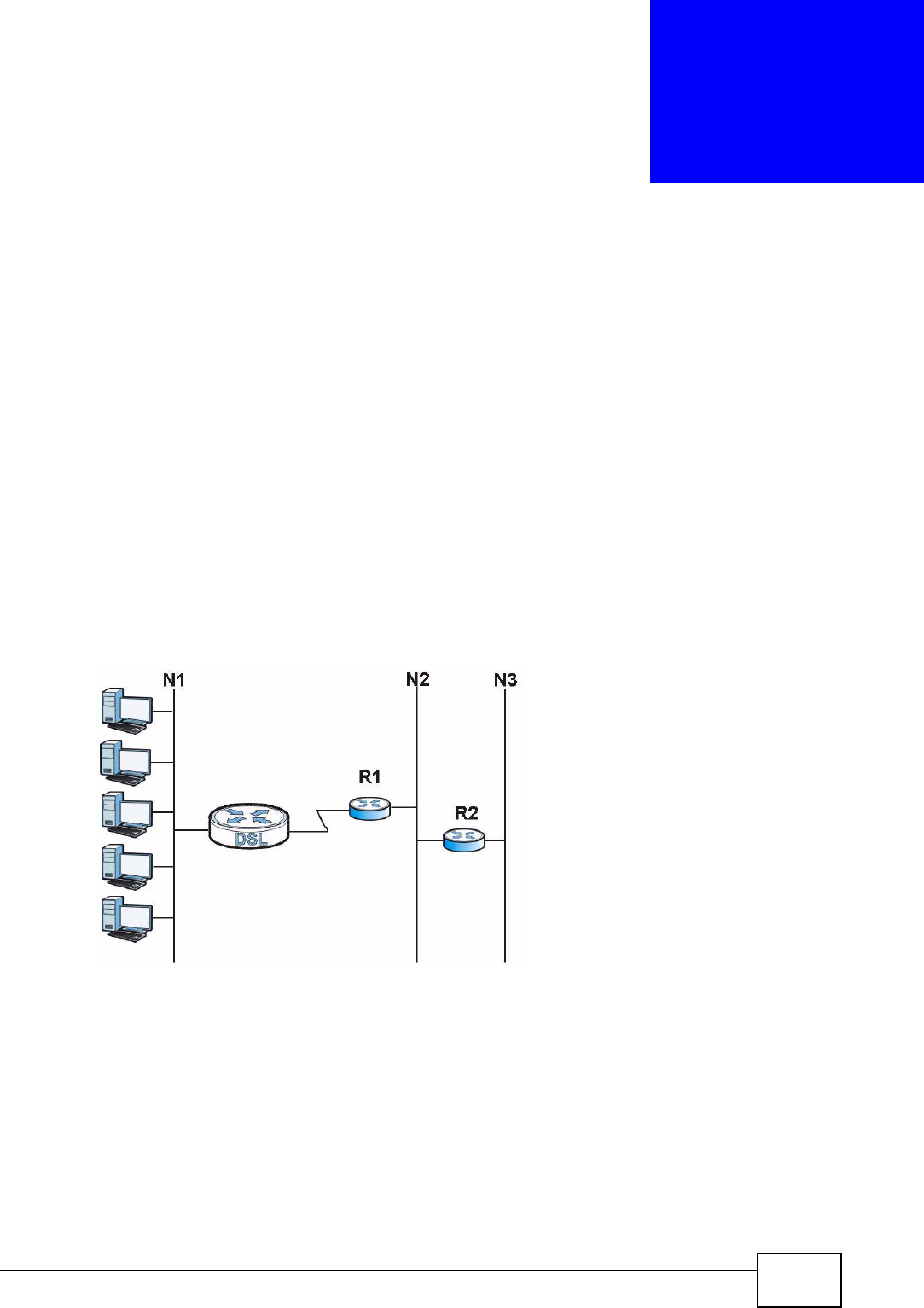
NBG4615 User’s Guide 189
CHAPTER 21
Static Route
21.1 Overview
This chapter shows you how to configure static routes for your NBG4615.
Each remote node specifies only the network to which the gateway is directly
connected, and the NBG4615 has no knowledge of the networks beyond. For
instance, the NBG4615 knows about network N2 in the following figure through
remote node Router 1. However, the NBG4615 is unable to route a packet to
network N3 because it doesn't know that there is a route through the same
remote node Router 1 (via gateway Router 2). The static routes are for you to tell
the NBG4615 about the networks beyond the remote nodes.
Figure 109 Example of Static Routing Topology
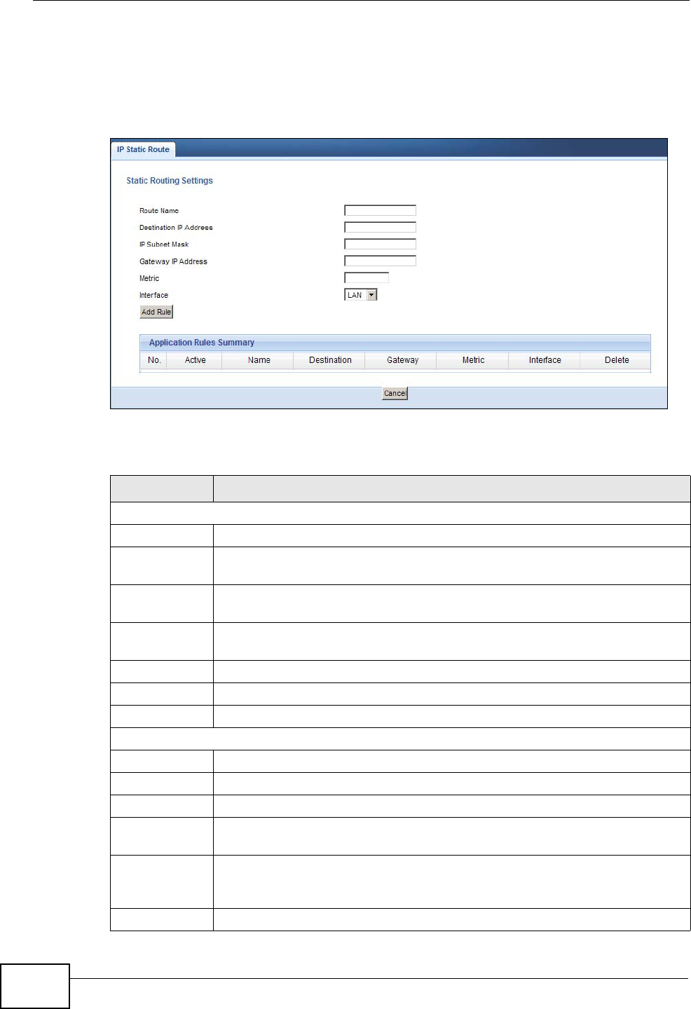
Chapter 21 Static Route
NBG4615 User’s Guide
190
21.2 IP Static Route Screen
Click Network > Static Route to open the IP Static Route screen.
Figure 110 Network > Static Route
The following table describes the labels in this screen.
Table 69 Network > Static Route
LABEL DESCRIPTION
Static Routing Settings
Route Name Enter a the name that describes or identifies this route.
Destination IP
Address Enter the IP network address of the final destination.
IP Subnet
Netmask This is the subnet to which the route’s final destination belongs.
Gateway IP
Address Enter the IP address of the gateway.
Metric Assign a number to identify the route.
Interface Select the interface through which the traffic is routed.
Add Rule Click this to add the IP static route.
Application Rules Summary
No. This is the number of an individual static route.
Active The rules are always on and this is indicated by the icon.
Name This is the name that describes or identifies this route.
Destination This parameter specifies the IP network address of the final destination.
Routing is always based on network number.
Gateway This is the IP address of the gateway. The gateway is a router or switch
on the same network segment as the device's LAN or WAN port. The
gateway helps forward packets to their destinations.
Metric This is the number assigned to the route.

Chapter 21 Static Route
NBG4615 User’s Guide 191
Delete Click the Delete icon to remove a static route from the NBG4615. A
window displays asking you to confirm that you want to delete the route.
Cancel Click Cancel to begin configuring this screen afresh.
Table 69 Network > Static Route (continued)
LABEL DESCRIPTION

Chapter 21 Static Route
NBG4615 User’s Guide
192
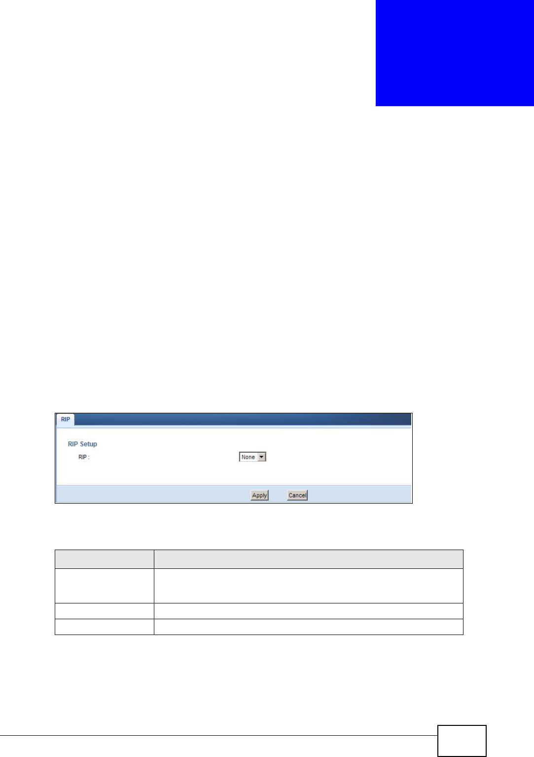
NBG4615 User’s Guide 193
CHAPTER 22
RIP
22.1 Overview
Routing Information Protocol (RIP) is an interior or intra-domain routing protocol
that uses distance-vector routing algorithms. RIP is used on the Internet and is
common in the NetWare environment as a method for exchanging routing
information between routers.
22.2 RIP Screen
Use this screen to enable RIPv1 or RIPv2, which are LAN broadcast protocols. Click
Network > RIP. The screen appears as shown.
Figure 111 Network > RIP
The following table describes the labels in this screen.
Table 70 Network > RIP
LABEL DESCRIPTION
RIP Select the RIPv1 or RIPv2 you want the NBG4615 to use.
Otherwise select None.
Apply Click Apply to save your changes back to the NBG4615.
Cancel Click Cancel to begin configuring this screen afresh.

Chapter 22 RIP
NBG4615 User’s Guide
194
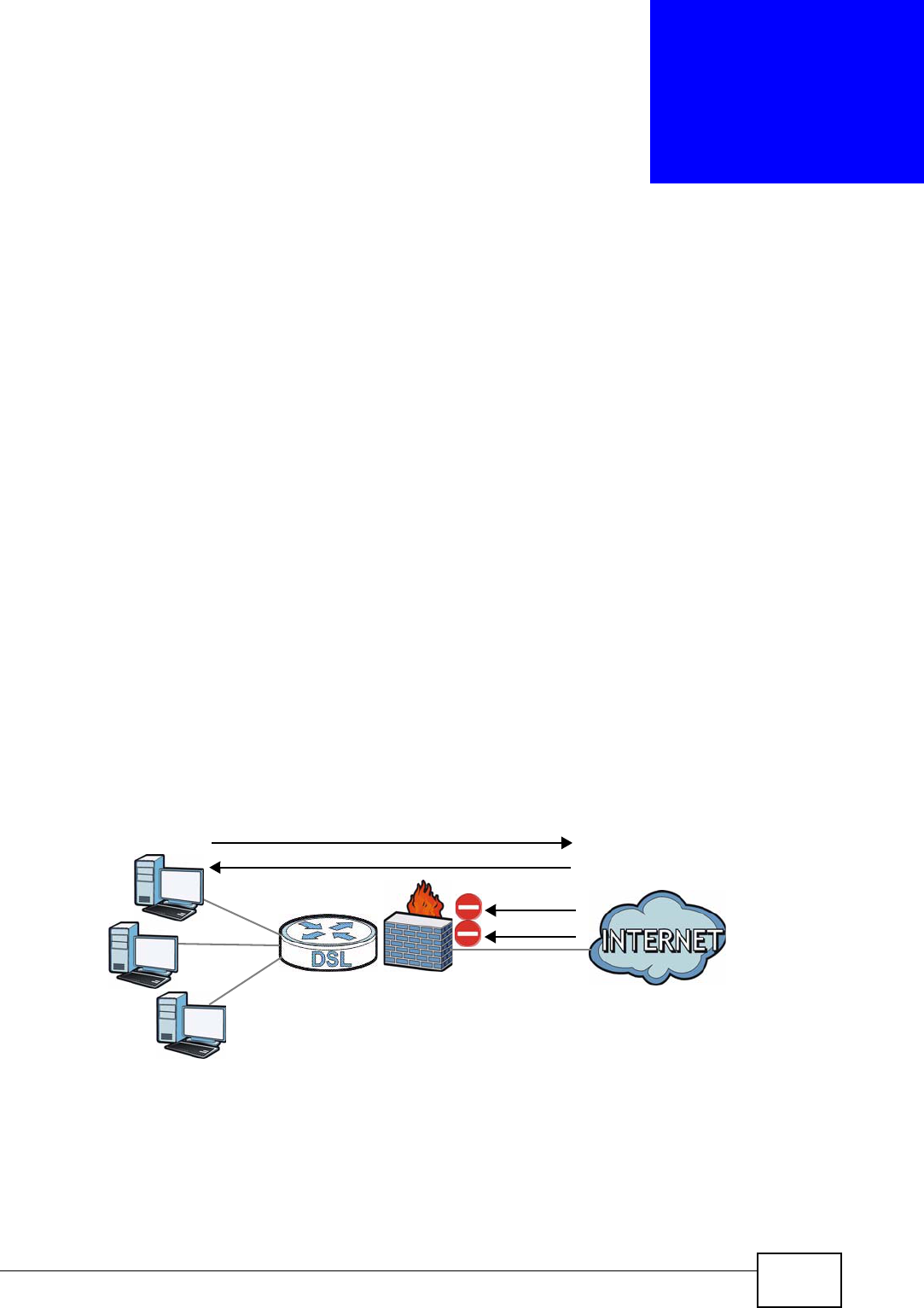
NBG4615 User’s Guide 195
CHAPTER 23
Firewall
23.1 Overview
Use these screens to enable and configure the firewall that protects your NBG4615
and your LAN from unwanted or malicious traffic.
Enable the firewall to protect your LAN computers from attacks by hackers on the
Internet and control access between the LAN and WAN. By default the firewall:
• allows traffic that originates from your LAN computers to go to all of the
networks.
• blocks traffic that originates on the other networks from going to the LAN.
The following figure illustrates the default firewall action. User A can initiate an IM
(Instant Messaging) session from the LAN to the WAN (1). Return traffic for this
session is also allowed (2). However other traffic initiated from the WAN is blocked
(3 and 4).
Figure 112 Default Firewall Action
23.1.1 What You Can Do
•Use the General screen to enable or disable the NBG4615’s firewall (Section
23.2 on page 198).
WAN
LAN
3
4
1
2
A

Chapter 23 Firewall
NBG4615 User’s Guide
196
•Use the Services screen enable service blocking, enter/delete/modify the
services you want to block and the date/time you want to block them (Section
23.3 on page 198).
23.1.2 What You Need To Know
The following terms and concepts may help as you read through this chapter.
What is a Firewall?
Originally, the term “firewall” referred to a construction technique designed to
prevent the spread of fire from one room to another. The networking term
"firewall" is a system or group of systems that enforces an access-control policy
between two networks. It may also be defined as a mechanism used to protect a
trusted network from a network that is not trusted. Of course, firewalls cannot
solve every security problem. A firewall is one of the mechanisms used to
establish a network security perimeter in support of a network security policy. It
should never be the only mechanism or method employed. For a firewall to guard
effectively, you must design and deploy it appropriately. This requires integrating
the firewall into a broad information-security policy. In addition, specific policies
must be implemented within the firewall itself.
Stateful Inspection Firewall
Stateful inspection firewalls restrict access by screening data packets against
defined access rules. They make access control decisions based on IP address and
protocol. They also "inspect" the session data to assure the integrity of the
connection and to adapt to dynamic protocols. These firewalls generally provide
the best speed and transparency; however, they may lack the granular application
level access control or caching that some proxies support. Firewalls, of one type or
another, have become an integral part of standard security solutions for
enterprises.
About the NBG4615 Firewall
The NBG4615’s firewall feature physically separates the LAN and the WAN and
acts as a secure gateway for all data passing between the networks.
It is a stateful inspection firewall and is designed to protect against Denial of
Service attacks when activated (click the General tab under Firewall and then
click the Enable Firewall check box). The NBG4615's purpose is to allow a
private Local Area Network (LAN) to be securely connected to the Internet. The
NBG4615 can be used to prevent theft, destruction and modification of data, as
well as log events, which may be important to the security of your network.

Chapter 23 Firewall
NBG4615 User’s Guide 197
The NBG4615 is installed between the LAN and a broadband modem connecting to
the Internet. This allows it to act as a secure gateway for all data passing between
the Internet and the LAN.
The NBG4615 has one Ethernet WAN port and four Ethernet LAN ports, which are
used to physically separate the network into two areas.The WAN (Wide Area
Network) port attaches to the broadband (cable or DSL) modem to the Internet.
The LAN (Local Area Network) port attaches to a network of computers, which
needs security from the outside world. These computers will have access to
Internet services such as e-mail, FTP and the World Wide Web. However, "inbound
access" is not allowed (by default) unless the remote host is authorized to use a
specific service.
Guidelines For Enhancing Security With Your Firewall
1Change the default password via Web Configurator.
2Think about access control before you connect to the network in any way,
including attaching a modem to the port.
3Limit who can access your router.
4Don't enable any local service (such as NTP) that you don't use. Any enabled
service could present a potential security risk. A determined hacker might be able
to find creative ways to misuse the enabled services to access the firewall or the
network.
5For local services that are enabled, protect against misuse. Protect by configuring
the services to communicate only with specific peers, and protect by configuring
rules to block packets for the services at specific interfaces.
6Protect against IP spoofing by making sure the firewall is active.
7Keep the firewall in a secured (locked) room.
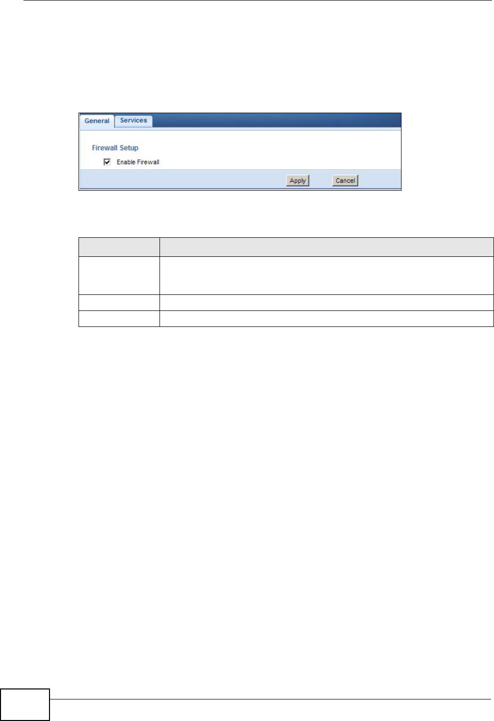
Chapter 23 Firewall
NBG4615 User’s Guide
198
23.2 General
Use this screen to enable or disable the NBG4615’s firewall, and set up firewall
logs. Click Security > Firewall to open the General screen.
Figure 113 Security > Firewall > General l
The following table describes the labels in this screen.
23.3 Services
If an outside user attempts to probe an unsupported port on your NBG4615, an
ICMP response packet is automatically returned. This allows the outside user to
know the NBG4615 exists. Use this screen to prevent the ICMP response packet
from being sent. This keeps outsiders from discovering your NBG4615 when
unsupported ports are probed.
You can also use this screen to enable service blocking, enter/delete/modify the
services you want to block and the date/time you want to block them.
Table 71 Security > Firewall > General
LABEL DESCRIPTION
Enable Firewall Select this check box to activate the firewall. The NBG4615 performs
access control and protects against Denial of Service (DoS) attacks
when the firewall is activated.
Apply Click Apply to save the settings.
Cancel Click Cancel to start configuring this screen again.
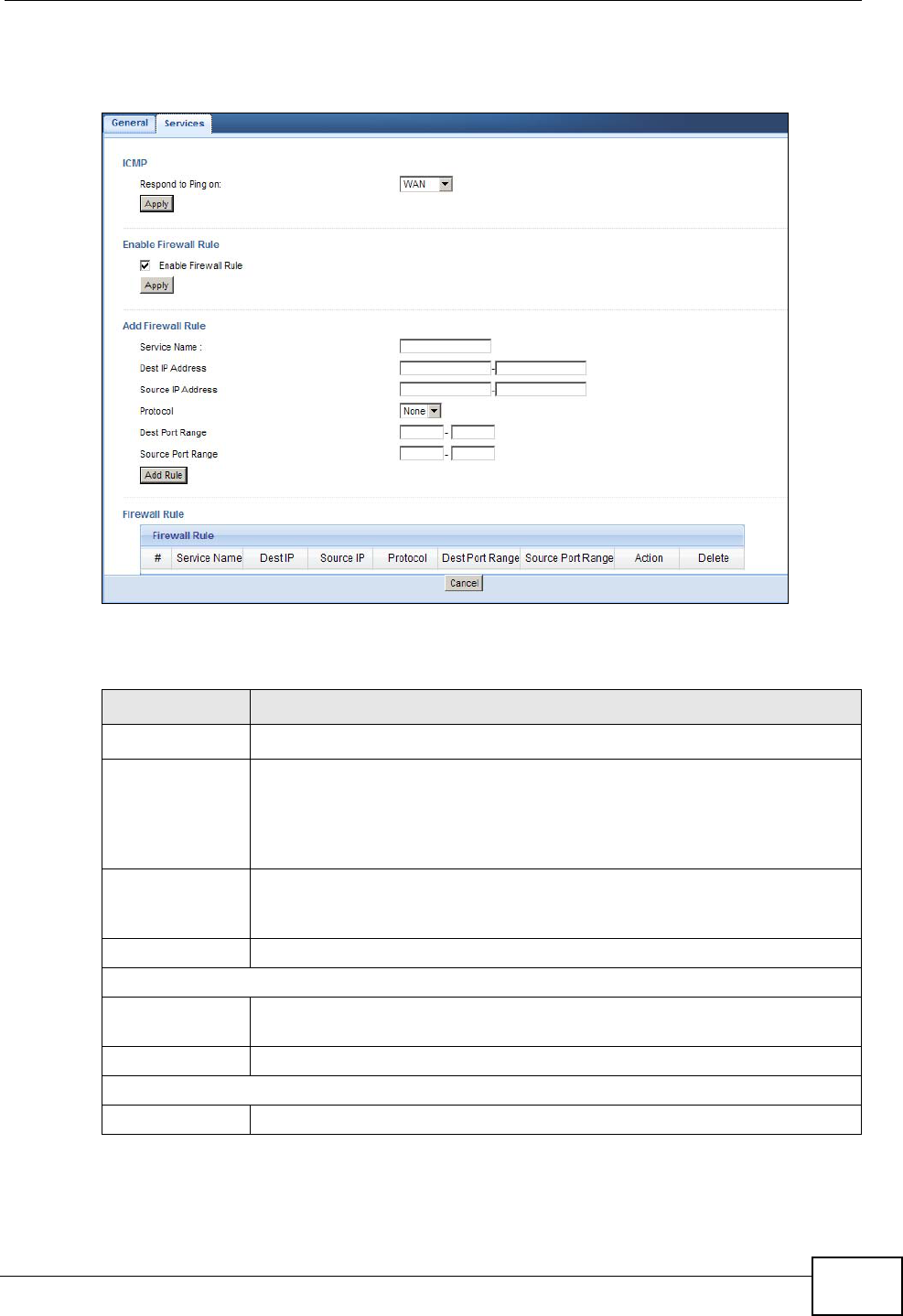
Chapter 23 Firewall
NBG4615 User’s Guide 199
Click Security > Firewall > Services. The screen appears as shown next.
Figure 114 Security > Firewall > Services l
The following table describes the labels in this screen.
Table 72 Security > Firewall > Services
LABEL DESCRIPTION
LABEL DESCRIPTION
ICMP Internet Control Message Protocol is a message control and error-
reporting protocol between a host server and a gateway to the Internet.
ICMP uses Internet Protocol (IP) datagrams, but the messages are
processed by the TCP/IP software and directly apparent to the
application user.
Respond to Ping
on The NBG4615 will not respond to any incoming Ping requests when
Disable is selected. Select WAN to reply to incoming WAN Ping
requests.
Apply Click Apply to save the settings.
Enable Firewall Rule
Enable Firewall
Rule Select this check box to activate the firewall rules that you define (see
Add Firewall Rule below).
Apply Click Apply to save the settings.
Add Firewall Rule
Service Name Enter a name that identifies or describes the firewall rule.

Chapter 23 Firewall
NBG4615 User’s Guide
200
See Appendix F on page 321 for commonly used services and port numbers.
Dest IP Address Enter the IP address of the computer to which traffic for the application
or service is entering.
The NBG4615 applies the firewall rule to traffic initiating from this
computer.
Source IP
Address Enter the IP address of the computer that initializes traffic for the
application or service.
The NBG4615 applies the firewall rule to traffic initiating from this
computer.
Protocol Select the protocol (ALL,TCP, UDP or BOTH) used to transport the
packets for which you want to apply the firewall rule.
Dest Port Range Enter the port number/range of the destination that define the traffic
type, for example TCP port 80 defines web traffic.
Source Port
Range Enter the port number/range of the source that define the traffic type,
for example TCP port 80 defines web traffic.
Add Rule Click Add to save the firewall rule.
Firewall Rule
#This is your firewall rule number. The ordering of your rules is important
as rules are applied in turn.
Service Name This is a name that identifies or describes the firewall rule.
Dest IP This is the IP address of the computer to which traffic for the application
or service is entering.
Source IP This is the IP address of the computer from which traffic for the
application or service is initialized.
Protocol This is the protocol (ALL,TCP, UDP or BOTH) used to transport the
packets for which you want to apply the firewall rule.
Dest Port Range This is the port number/range of the destination that define the traffic
type, for example TCP port 80 defines web traffic.
Source Port
Range This is the port number/range of the source that define the traffic type,
for example TCP port 80 defines web traffic.
Action Drop - Traffic matching the conditions of the firewall rule are stopped.
Delete Click Delete to remove the firewall rule.
Cancel Click Cancel to start configuring this screen again.
Table 72 Security > Firewall > Services (continued)
LABEL DESCRIPTION

NBG4615 User’s Guide 201
CHAPTER 24
Content Filtering
24.1 Overview
This chapter provides a brief overview of content filtering using the embedded
web GUI.
Internet content filtering allows you to create and enforce Internet access policies
tailored to your needs. Content filtering is the ability to block certain web features
or specific URL keywords.
24.1.1 What You Need To Know
The following terms and concepts may help as you read through this chapter.
Content Filtering Profiles
Content filtering allows you to block certain web features, such as cookies, and/or
block access to specific web sites. For example, you can configure one policy that
blocks John Doe’s access to arts and entertainment web pages.
A content filtering profile conveniently stores your custom settings for the
following features.
Keyword Blocking URL Checking
The NBG4615 checks the URL’s domain name (or IP address) and file path
separately when performing keyword blocking.
The URL’s domain name or IP address is the characters that come before the first
slash in the URL. For example, with the URL www.zyxel.com.tw/news/
pressroom.php, the domain name is www.zyxel.com.tw.
The file path is the characters that come after the first slash in the URL. For
example, with the URL www.zyxel.com.tw/news/pressroom.php, the file path is
news/pressroom.php.
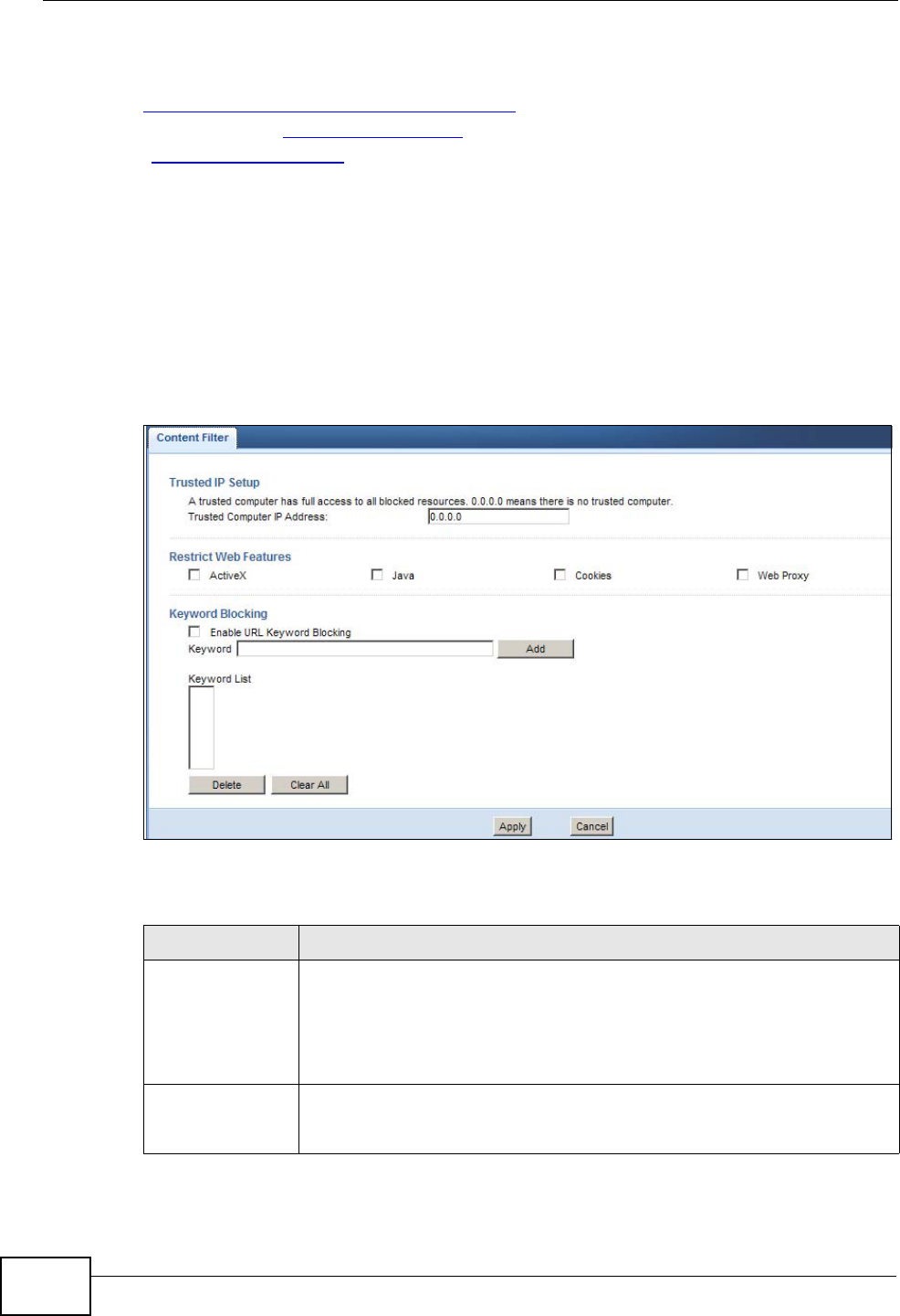
Chapter 24 Content Filtering
NBG4615 User’s Guide
202
Since the NBG4615 checks the URL’s domain name (or IP address) and file path
separately, it will not find items that go across the two. For example, with the URL
www.zyxel.com.tw/news/pressroom.php, the NBG4615 would find “tw” in the
domain name (www.zyxel.com.tw). It would also find “news” in the file path
(news/pressroom.php) but it would not find “tw/news”.
24.2 Content Filter
Use this screen to restrict web features, add keywords for blocking and designate
a trusted computer. Click Security > Content Filter to open the Content Filter
screen.
Figure 115 Security > Content Filter
The following table describes the labels in this screen.
Table 73 Security > Content Filter
LABEL DESCRIPTION
Trusted IP Setup To enable this feature, type an IP address of any one of the computers
in your network that you want to have as a trusted computer. This
allows the trusted computer to have full access to all features that are
configured to be blocked by content filtering.
Leave this field blank to have no trusted computers.
Restrict Web
Features Select the box(es) to restrict a feature. When you download a page
containing a restricted feature, that part of the web page will appear
blank or grayed out.

Chapter 24 Content Filtering
NBG4615 User’s Guide 203
24.3 Technical Reference
The following section contains additional technical information about the NBG4615
features described in this chapter.
24.3.1 Customizing Keyword Blocking URL Checking
You can use commands to set how much of a website’s URL the content filter is to
check for keyword blocking. See the appendices for information on how to access
and use the command interpreter.
Domain Name or IP Address URL Checking
By default, the NBG4615 checks the URL’s domain name or IP address when
performing keyword blocking.
This means that the NBG4615 checks the characters that come before the first
slash in the URL.
For example, with the URL www.zyxel.com.tw/news/pressroom.php, content
filtering only searches for keywords within www.zyxel.com.tw.
Enable URL
Keyword
Blocking
The NBG4615 can block Web sites with URLs that contain certain
keywords in the domain name or IP address. For example, if the
keyword "bad" was enabled, all sites containing this keyword in the
domain name or IP address will be blocked, e.g., URL http://
www.website.com/bad.html would be blocked. Select this check box to
enable this feature.
Keyword Type a keyword in this field. You may use any character (up to 64
characters). Wildcards are not allowed. You can also enter a numerical
IP address.
Keyword List This list displays the keywords already added.
Add Click Add after you have typed a keyword.
Repeat this procedure to add other keywords. Up to 64 keywords are
allowed.
When you try to access a web page containing a keyword, you will get
a message telling you that the content filter is blocking this request.
Delete Highlight a keyword in the lower box and click Delete to remove it.
The keyword disappears from the text box after you click Apply.
Clear All Click this button to remove all of the listed keywords.
Apply Click Apply to save your changes.
Cancel Click Cancel to begin configuring this screen afresh
Table 73 Security > Content Filter (continued)
LABEL DESCRIPTION

Chapter 24 Content Filtering
NBG4615 User’s Guide
204
Full Path URL Checking
Full path URL checking has the NBG4615 check the characters that come before
the last slash in the URL.
For example, with the URL www.zyxel.com.tw/news/pressroom.php, full path URL
checking searches for keywords within www.zyxel.com.tw/news/.
Use the ip urlfilter customize actionFlags 6 [disable | enable]
command to extend (or not extend) the keyword blocking search to include the
URL's full path.
File Name URL Checking
Filename URL checking has the NBG4615 check all of the characters in the URL.
For example, filename URL checking searches for keywords within the URL
www.zyxel.com.tw/news/pressroom.php.
Use the ip urlfilter customize actionFlags 8 [disable | enable]
command to extend (or not extend) the keyword blocking search to include the
URL's complete filename.
NBG4615 User’s Guide 205
CHAPTER 25
Bandwidth Management
25.1 Overview
This chapter contains information about configuring bandwidth management and
editing rules.
ZyXEL’s Bandwidth Management allows you to specify bandwidth management
rules based on an application.
In the figure below, uplink traffic goes from the LAN device (A) to the WAN device
(B). Bandwidth management is applied before sending the packets out to the
WAN. Downlink traffic comes back from the WAN device (B) to the LAN device (A).
Bandwidth management is applied before sending the traffic out to LAN.
Figure 116 Bandwidth Management Example
You can allocate specific amounts of bandwidth capacity (bandwidth budgets) to
individual applications (like VoIP, Web, FTP, and E-mail for example).
25.2 What You Can Do
•Use the General screen to enable bandwidth management and assign
bandwidth values (Section 25.4 on page 206).
•Use the Advanced screen to configure bandwidth managements rule for the
pre-defined services and applications (Section 25.5 on page 207).
AB
-> VOIP
-> FTP
-> HTTP
-> Chat, Email
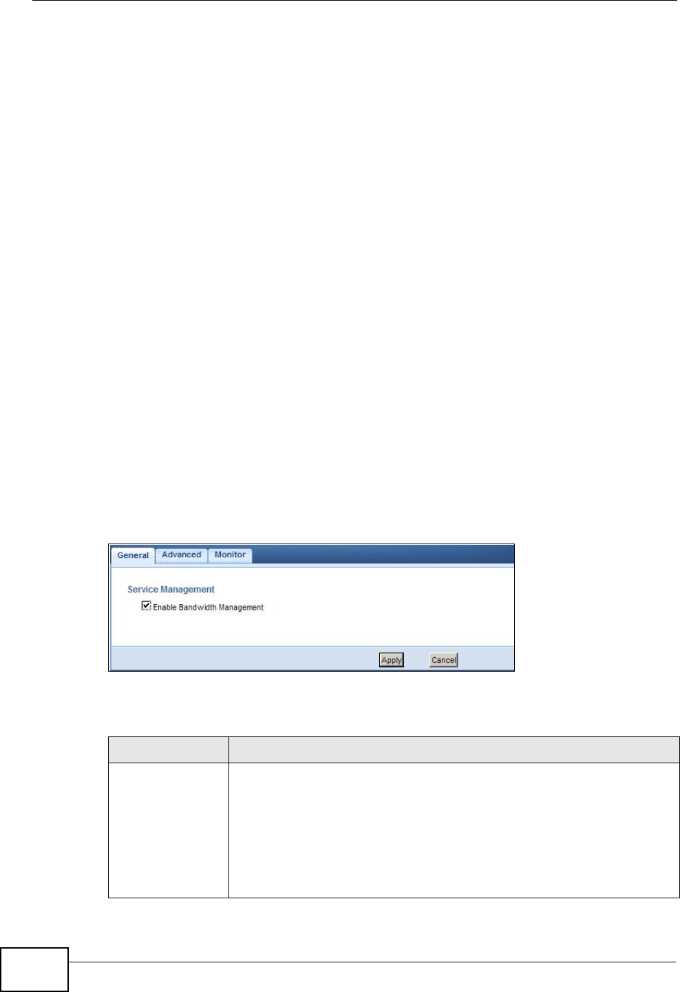
Chapter 25 Bandwidth Management
NBG4615 User’s Guide
206
•Use the Monitor screen to view the amount of network bandwidth that
applications running in the network are using (Section 25.6 on page 211).
25.3 What You Need To Know
The sum of the bandwidth allotments that apply to the WAN interface (LAN to
WAN, WLAN to WAN) must be less than or equal to the Upstream Bandwidth
that you configure in the Bandwidth Management Advanced screen (Section
25.5 on page 207).
The sum of the bandwidth allotments that apply to the LAN interface (WAN to
LAN, WAN to WLAN) must be less than or equal to the Downstream Bandwidth
that you configure in the Bandwidth Management Advanced screen Section
25.5 on page 207.
25.4 General Screen
Use this screen to have the NBG4615 apply bandwidth management.
Click Management > Bandwidth MGMT to open the bandwidth management
General screen.
Figure 117 Management > Bandwidth Management > General
The following table describes the labels in this screen.
Table 74 Management > Bandwidth Management > General
LABEL DESCRIPTION
Enable
Bandwidth
Management
This field allows you to have NBG4615 apply bandwidth management.
Enable bandwidth management to give traffic that matches a
bandwidth rule priority over traffic that does not match a bandwidth
rule.
Enabling bandwidth management also allows you to control the
maximum or minimum amounts of bandwidth that can be used by
traffic that matches a bandwidth rule.

Chapter 25 Bandwidth Management
NBG4615 User’s Guide 207
25.5 Advanced Screen
Use this screen to configure bandwidth management rules for the pre-defined
services or applications.
You can also use this screen to configure bandwidth management rule for other
services or applications that are not on the pre-defined list of NBG4615.
Additionally, you can define the source and destination IP addresses and port for a
service or application.
Note: The two tables shown in this screen can be configured and applied at the same
time.
Apply Click Apply to save your customized settings.
Cancel Click Cancel to begin configuring this screen afresh.
Table 74 Management > Bandwidth Management > General (continued)
LABEL DESCRIPTION
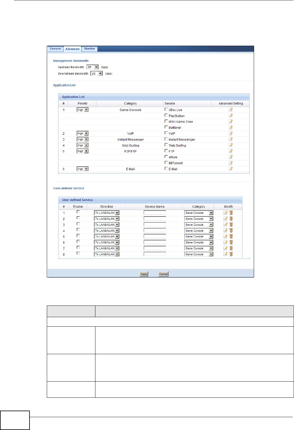
Chapter 25 Bandwidth Management
NBG4615 User’s Guide
208
Click Management > Bandwidth Management > Advanced to open the
bandwidth management Advanced screen.
Figure 118 Management > Bandwidth Management > Advanced
The following table describes the labels in this screen.
Table 75 Management > Bandwidth Management > Advanced
LABEL DESCRIPTION
Management Bandwidth
Upstream
Bandwidth Select the total amount of bandwidth (from 64 Kilobits to 32 Megabits)
that you want to dedicate to uplink traffic.
This is traffic from LAN/WLAN to WAN.
Downstream
Bandwidth Select the total amount of bandwidth (from 64 Kilobits to 32 Megabits)
that you want to dedicate to uplink traffic.
This is traffic from WAN to LAN/WLAN.
Application List Use this table to allocate specific amounts of bandwidth based on a pre-
defined service.
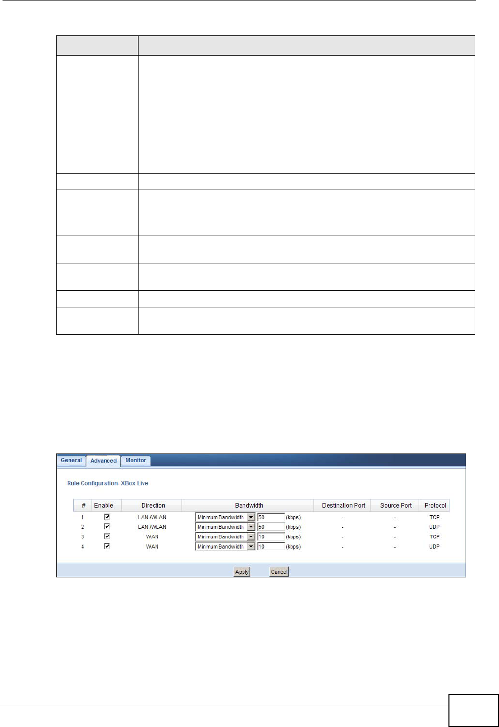
Chapter 25 Bandwidth Management
NBG4615 User’s Guide 209
25.5.1 Rule Configuration: Application Rule Configuration
If you want to edit a bandwidth management rule for a pre-defined service or
application, click the Edit icon in the Application List table of the Advanced
screen. The following screen displays.
Figure 119 Bandwidth Management Rule Configuration: Application List
Priority Select a priority from the drop down list box. Choose High, Mid or
Low.
•High - Select this for voice traffic or video that is especially sensitive
to jitter (jitter is the variations in delay).
•Mid - Select this for "excellent effort" or better than best effort and
would include important business traffic that can tolerate some
delay.
•Low - Select this for non-critical "background" traffic such as bulk
transfers that are allowed but that should not affect other
applications and users.
Category This is the category where a service belongs.
Service This is the name of the service.
Select the check box to have the NBG4615 apply this bandwidth
management rule.
Advanced
Setting Click the Edit icon to open the Rule Configuration screen where you
can modify the rule.
User-defined
Service Use this table to allocate specific amounts of bandwidth to specific
applications or services you specify.
#This is the number of an individual bandwidth management rule.
Enable Select this check box to have the NBG4615 apply this bandwidth
management rule.
Table 75 Management > Bandwidth Management > Advanced (continued)
LABEL DESCRIPTION
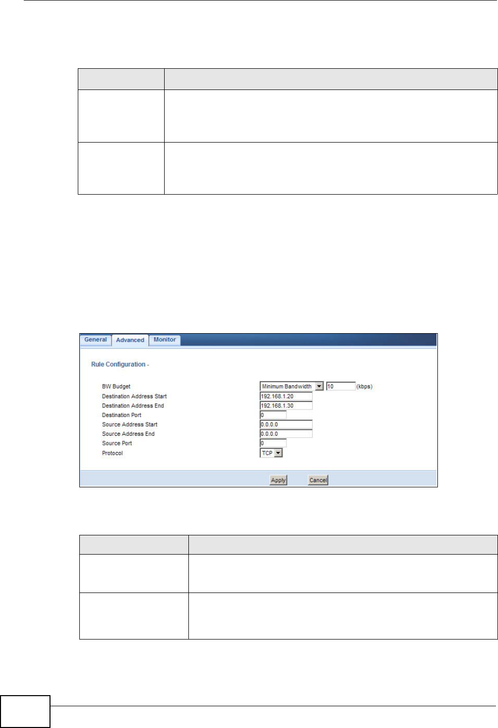
Chapter 25 Bandwidth Management
NBG4615 User’s Guide
210
The following table describes the labels in this screen.
25.5.2 Rule Configuration: User Defined Service Rule
Configuration
If you want to edit a bandwidth management rule for other applications or
services, click the Edit icon in the User-defined Service table of the Advanced
screen. The following screen displays.
Figure 120 Bandwidth Management Rule Configuration: User-defined Service
The following table describes the labels in this screen.
Table 76 Bandwidth Management Rule Configuration: Application List
LABEL DESCRIPTION
This is the port number of the destination that define the traffic type,
for example TCP port 80 defines web traffic.
See Appendix F on page 321 for some common services and port
numbers.
This is the port number of the source that define the traffic type, for
example TCP port 80 defines web traffic.
See Appendix F on page 321 for some common services and port
numbers.
Table 77 Bandwidth Management Rule Configuration: User-defined Service
LABEL DESCRIPTION
BW Budget Select Maximum Bandwidth or Minimum Bandwidth and
specify the maximum or minimum bandwidth allowed for the rule
in kilobits per second.
Destination Address
Start Enter the starting IP address of the destination computer.
The NBG4615 applies bandwidth management to the service or
application that is entering this computer.

Chapter 25 Bandwidth Management
NBG4615 User’s Guide 211
See Appendix F on page 321 for commonly used services and port numbers.
25.6 Monitor Screen
Use this screen to view the amount of network bandwidth that applications
running in the network are using.
The bandwidth is measured in kilobits per second (kbps).
Destination Address
End Enter the ending IP address of the destination computer.
The NBG4615 applies bandwidth management to the service or
application that is entering this computer.
Destination Port This is the port number of the destination that define the traffic
type, for example TCP port 80 defines web traffic.
Source Address Start Enter the starting IP address of the computer that initializes
traffic for the application or service.
The NBG4615 applies bandwidth management to traffic initiating
from this computer.
Source Address End Enter the ending IP address of the computer that initializes traffic
for the application or service.
The NBG4615 applies bandwidth management to traffic initiating
from this computer.
Source Port This is the port number of the source that define the traffic type,
for example TCP port 80 defines web traffic.
Protocol Select the protocol (TCP, UDP, BOTH) for which the bandwidth
management rule applies.
If you select BOTH, enter the protocol for which the bandwidth
management rule applies. For example, ICMP for ping traffic.
Apply Click Apply to save your customized settings.
Cancel Click Cancel to exit this screen without saving.
Table 77 Bandwidth Management Rule Configuration: User-defined Service
LABEL DESCRIPTION
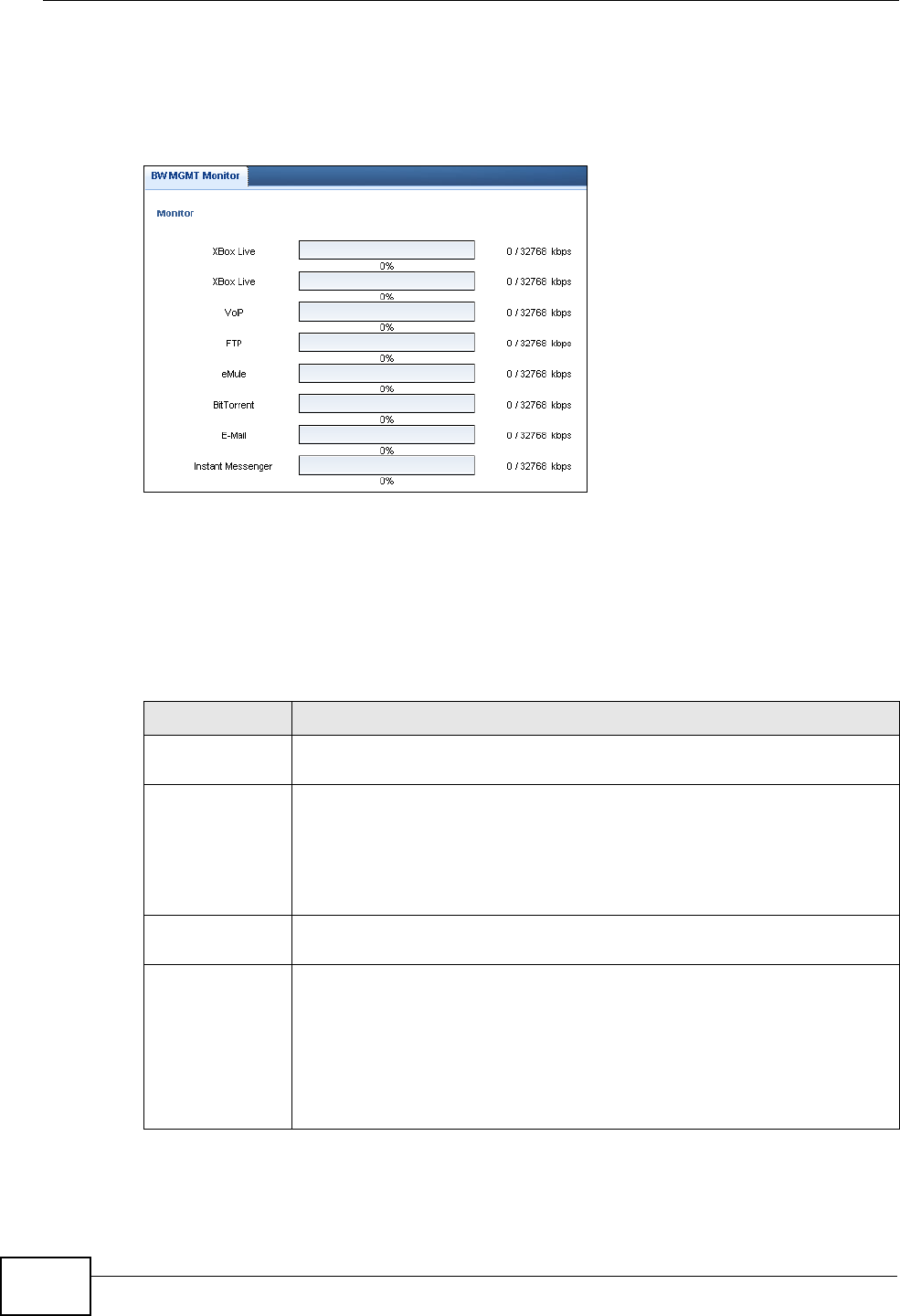
Chapter 25 Bandwidth Management
NBG4615 User’s Guide
212
The monitor shows what kinds of applications are running in the network, the
maximum kbps that each application can use, as well as the percentage of
bandwidth it is using.
Figure 121 Management > Bandwidth Management > Monitor
25.6.1 Predefined Bandwidth Management Services
The following is a description of some services that you can select and to which
you can apply media bandwidth management in the Management > Bandwidth
Management > Advanced screen.
Table 78 Media Bandwidth Management Setup: Services
SERVICE DESCRIPTION
FTP File Transfer Program enables fast transfer of files, including large files
that may not be possible by e-mail.
WWW The World Wide Web (WWW) is an Internet system to distribute
graphical, hyper-linked information, based on Hyper Text Transfer
Protocol (HTTP) - a client/server protocol for the World Wide Web. The
Web is not synonymous with the Internet; rather, it is just one service
on the Internet. Other services on the Internet include Internet Relay
Chat and Newsgroups. The Web is accessed through use of a browser.
E-Mail Electronic mail consists of messages sent through a computer network
to specific groups or individuals. Here are some default ports for e-mail:
VoIP (SIP) Sending voice signals over the Internet is called Voice over IP or VoIP.
Session Initiated Protocol (SIP) is an internationally recognized
standard for implementing VoIP. SIP is an application-layer control
(signaling) protocol that handles the setting up, altering and tearing
down of voice and multimedia sessions over the Internet.
SIP is transported primarily over UDP but can also be transported over
TCP.

Chapter 25 Bandwidth Management
NBG4615 User’s Guide 213
BitTorrent BitTorrent is a free P2P (peer-to-peer) sharing tool allowing you to
distribute large software and media files. BitTorrent requires you to
search for a file with a searching engine yourself. It distributes files by
corporation and trading, that is, the client downloads the file in small
pieces and share the pieces with other peers to get other half of the file.
Gaming Online gaming services lets you play multiplayer games on the Internet
via broadband technology. As of this writing, your NBG4615 supports
Xbox, Playstation, Battlenet and MSN Game Zone.
Table 78 Media Bandwidth Management Setup: Services (continued)
SERVICE DESCRIPTION

Chapter 25 Bandwidth Management
NBG4615 User’s Guide
214

NBG4615 User’s Guide 215
CHAPTER 26
Remote Management
26.1 Overview
This chapter provides information on the Remote Management screens.
Remote Management allows you to manage your NBG4615 from a remote location
through the following interfaces:
•LAN and WAN
•LAN only
•WAN only
Note: The NBG4615 is managed using the Web Configurator.
26.2 What You Need to Know
Remote management over LAN or WAN will not work when:
1The IP address in the Secured Client IP Address field (Section 26.3 on page
216) does not match the client IP address. If it does not match, the NBG4615 will
disconnect the session immediately.
2There is already another remote management session. You may only have one
remote management session running at one time.
3There is a firewall rule that blocks it.
26.2.1 Remote Management and NAT
When NAT is enabled:
• Use the NBG4615’s WAN IP address when configuring from the WAN.
• Use the NBG4615’s LAN IP address when configuring from the LAN.
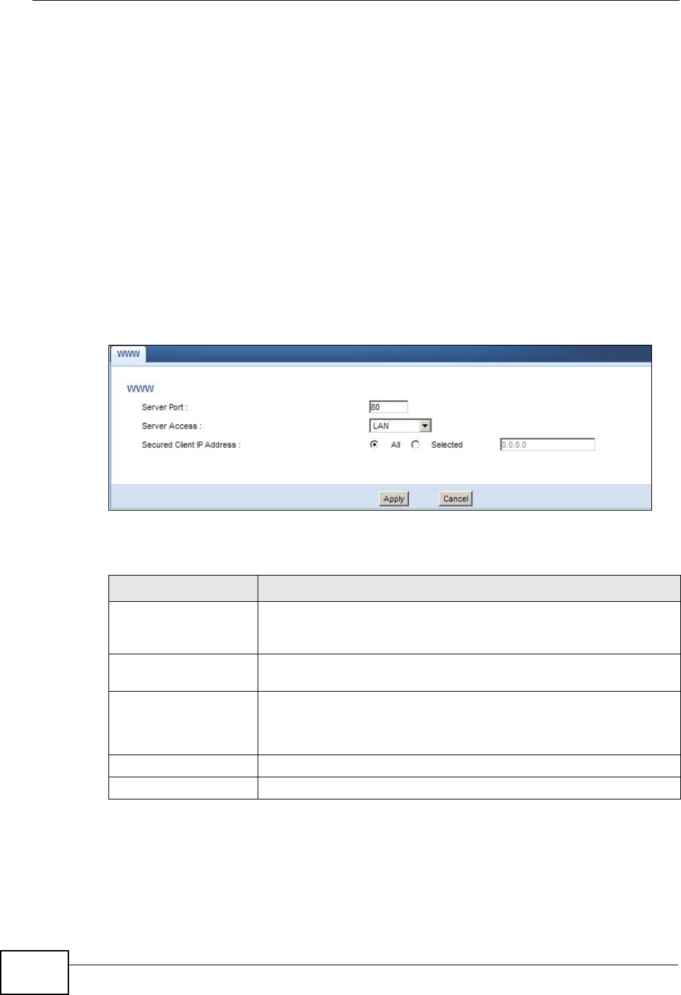
Chapter 26 Remote Management
NBG4615 User’s Guide
216
26.2.2 System Timeout
There is a default system management idle timeout of five minutes (three
hundred seconds). The NBG4615 automatically logs you out if the management
session remains idle for longer than this timeout period. The management session
does not time out when a statistics screen is polling. You can change the timeout
period in the System screen
26.3 WWW Screen
To change your NBG4615’s remote management settings, click Management >
Remote Management > WWW.
Figure 122 Management > Remote Management > WWW
The following table describes the labels in this screen.
Table 79 Management > Remote Management > WWW
LABEL DESCRIPTION
Server Port You may change the server port number for a service if needed,
however you must use the same port number in order to use that
service for remote management.
Server Access Select the interface(s) through which a computer may access the
NBG4615 using this service.
Secured Client IP
Address Select All to allow all computes to access the NBG4615.
Otherwise, check Selected and specify the IP address of the
computer that can access the NBG4615.
Apply Click Apply to save your customized settings and exit this screen.
Cancel Click Cancel to begin configuring this screen afresh.

NBG4615 User’s Guide 217
CHAPTER 27
Universal Plug-and-Play (UPnP)
27.1 Overview
This chapter introduces the UPnP feature in the web configurator.
Universal Plug and Play (UPnP) is a distributed, open networking standard that
uses TCP/IP for simple peer-to-peer network connectivity between devices. A
UPnP device can dynamically join a network, obtain an IP address, convey its
capabilities and learn about other devices on the network. In turn, a device can
leave a network smoothly and automatically when it is no longer in use.
27.2 What You Need to Know
UPnP hardware is identified as an icon in the Network Connections folder
(Windows XP). Each UPnP compatible device installed on your network will appear
as a separate icon. Selecting the icon of a UPnP device will allow you to access the
information and properties of that device.
27.2.1 NAT Traversal
UPnP NAT traversal automates the process of allowing an application to operate
through NAT. UPnP network devices can automatically configure network
addressing, announce their presence in the network to other UPnP devices and
enable exchange of simple product and service descriptions. NAT traversal allows
the following:
• Dynamic port mapping
• Learning public IP addresses
• Assigning lease times to mappings
Windows Messenger is an example of an application that supports NAT traversal
and UPnP.
See the NAT chapter for more information on NAT.
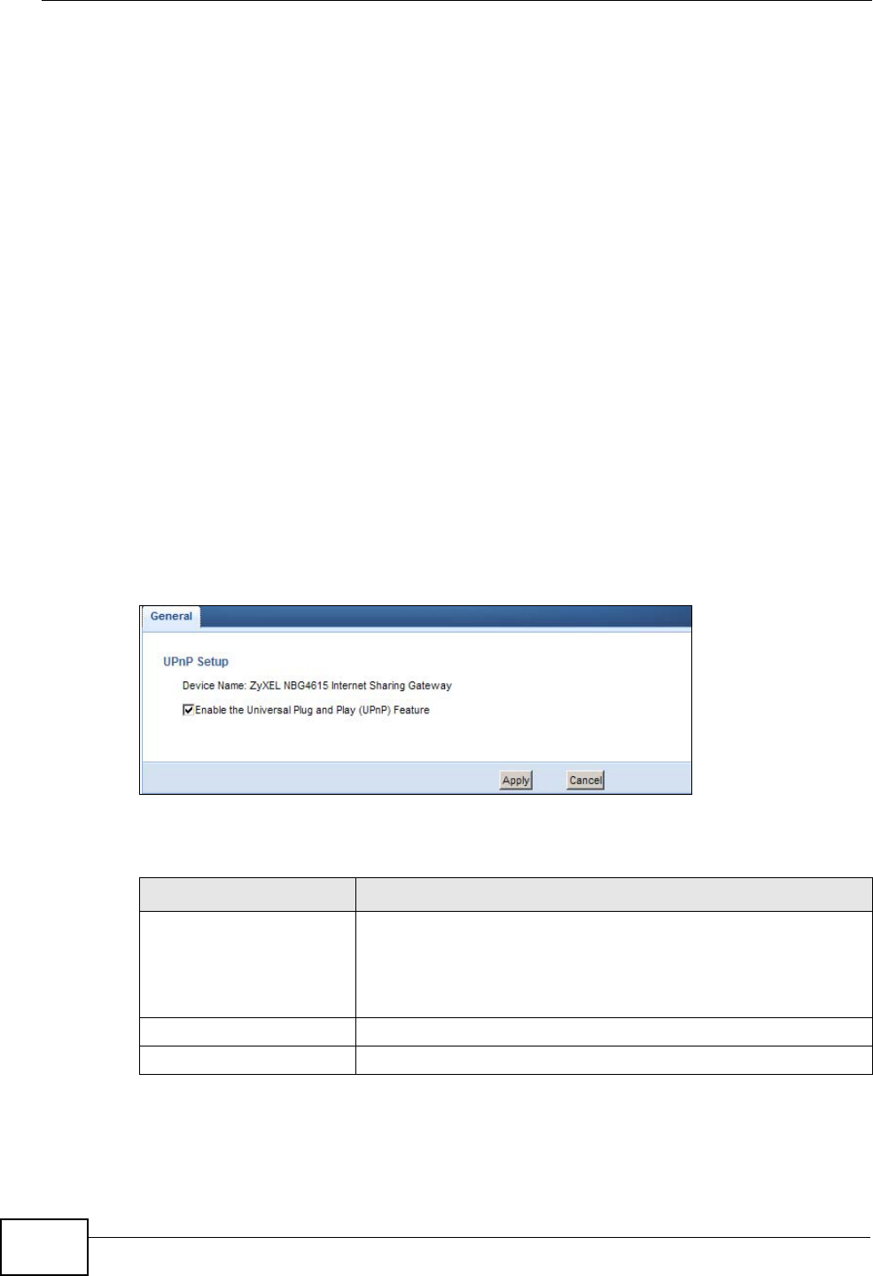
Chapter 27 Universal Plug-and-Play (UPnP)
NBG4615 User’s Guide
218
27.2.2 Cautions with UPnP
The automated nature of NAT traversal applications in establishing their own
services and opening firewall ports may present network security issues. Network
information and configuration may also be obtained and modified by users in some
network environments.
When a UPnP device joins a network, it announces its presence with a multicast
message. For security reasons, the NBG4615 allows multicast messages on the
LAN only.
All UPnP-enabled devices may communicate freely with each other without
additional configuration. Disable UPnP if this is not your intention.
27.3 UPnP Screen
Use this screen to enable UPnP on your NBG4615.
Click Management > UPnP to display the screen shown next.
Figure 123 Management > UPnP
The following table describes the fields in this screen.
Table 80 Management > UPnP
LABEL DESCRIPTION
Enable the Universal Plug
and Play (UPnP) Feature Select this check box to activate UPnP. Be aware that anyone
could use a UPnP application to open the web configurator's
login screen without entering the NBG4615's IP address
(although you must still enter the password to access the web
configurator).
Apply Click Apply to save the setting to the NBG4615.
Cancel Click Cancel to return to the previously saved settings.
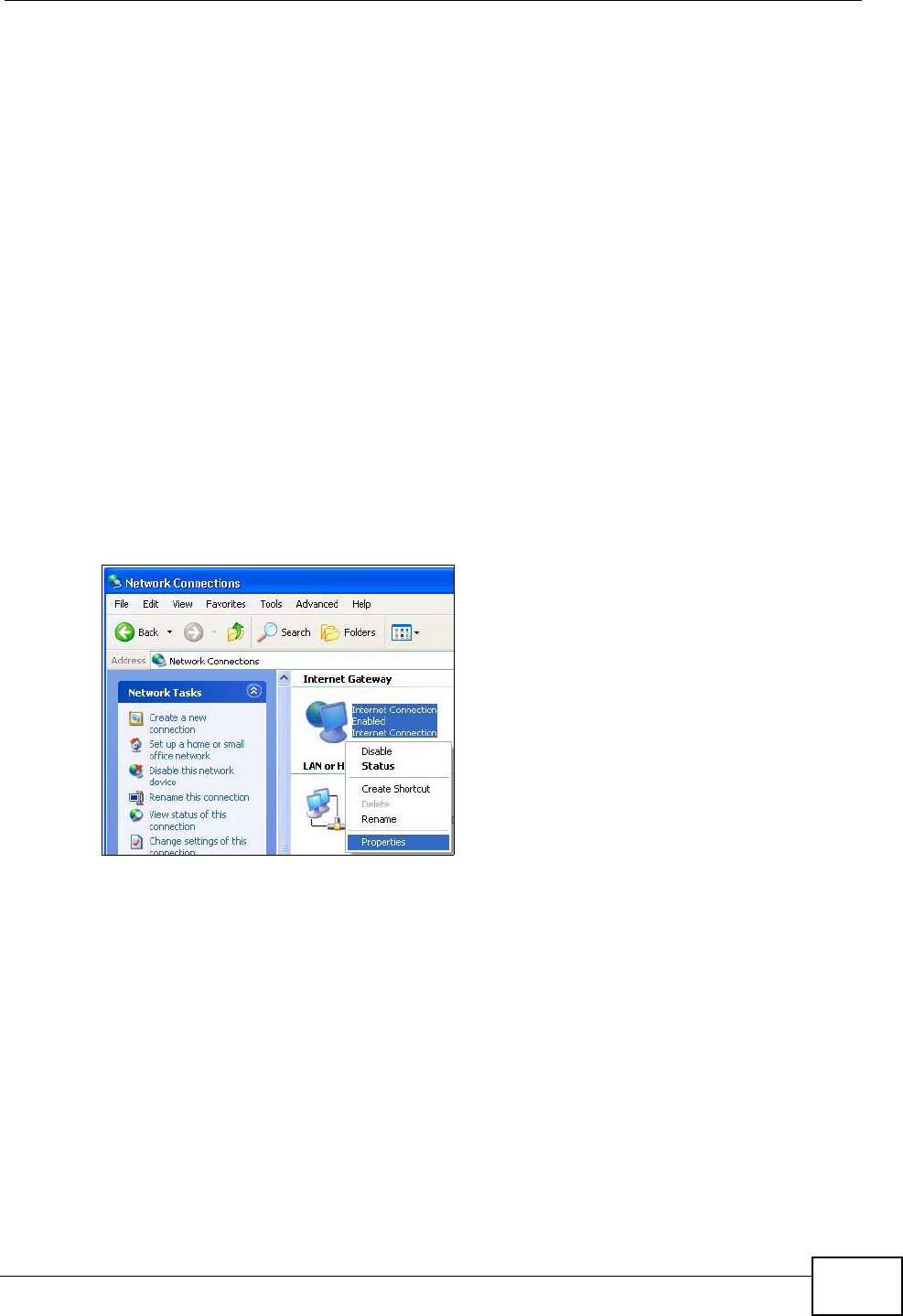
Chapter 27 Universal Plug-and-Play (UPnP)
NBG4615 User’s Guide 219
27.4 Technical Reference
The sections show examples of using UPnP.
27.4.1 Using UPnP in Windows XP Example
This section shows you how to use the UPnP feature in Windows XP. You must
already have UPnP installed in Windows XP and UPnP activated on the NBG4615.
Make sure the computer is connected to a LAN port of the NBG4615. Turn on your
computer and the NBG4615.
27.4.1.1 Auto-discover Your UPnP-enabled Network Device
1Click start and Control Panel. Double-click Network Connections. An icon
displays under Internet Gateway.
2Right-click the icon and select Properties.
Figure 124 Network Connections
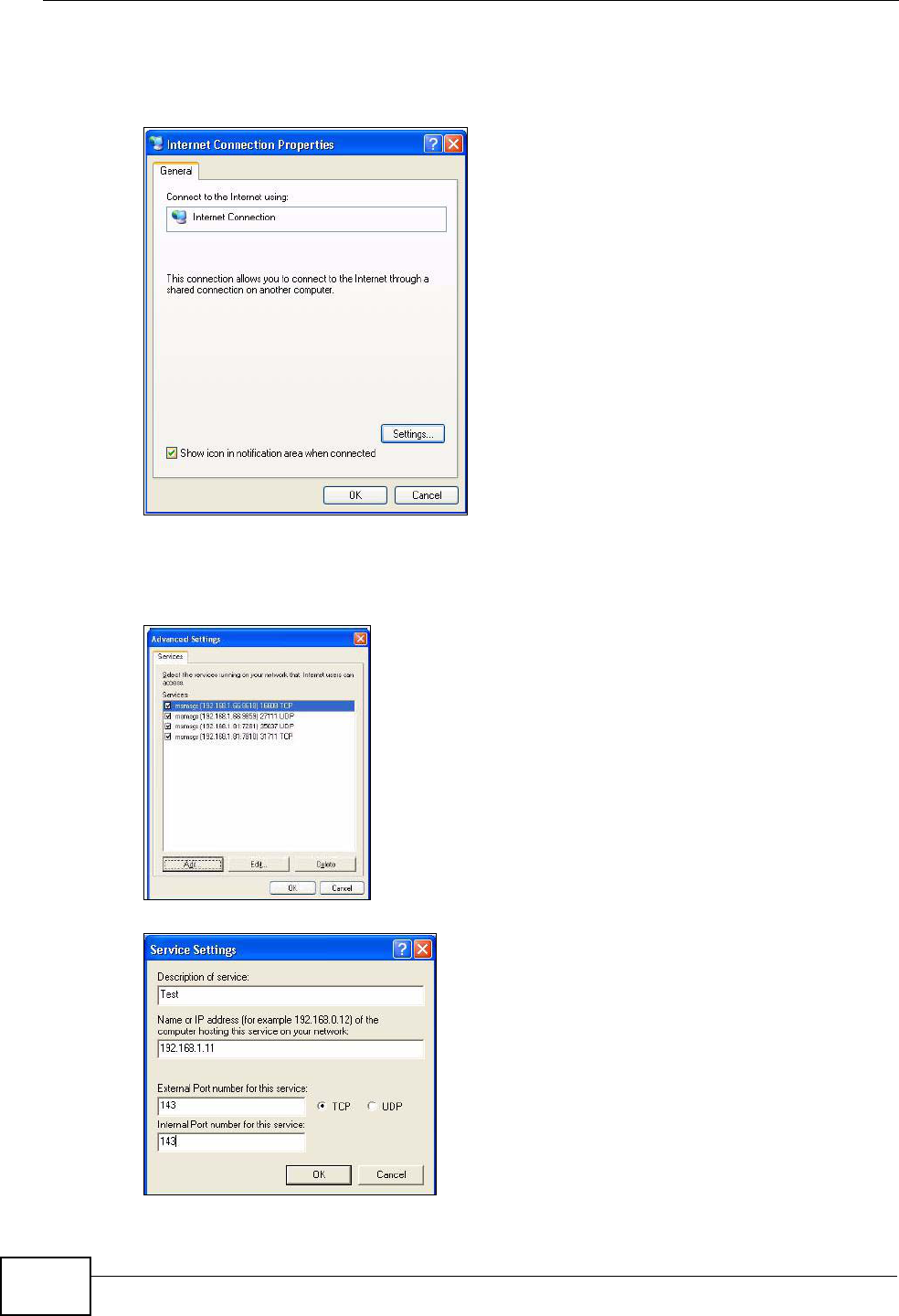
Chapter 27 Universal Plug-and-Play (UPnP)
NBG4615 User’s Guide
220
3In the Internet Connection Properties window, click Settings to see the port
mappings there were automatically created.
Figure 125 Internet Connection Properties
4You may edit or delete the port mappings or click Add to manually add port
mappings.
Figure 126 Internet Connection Properties: Advanced Settings
Figure 127 Internet Connection Properties: Advanced Settings: Add
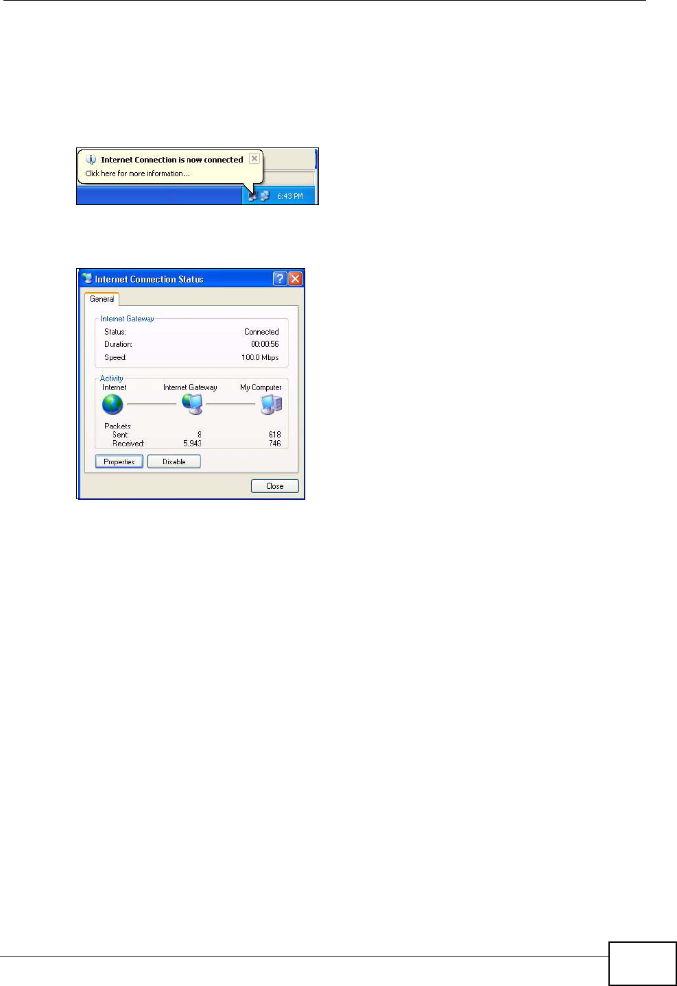
Chapter 27 Universal Plug-and-Play (UPnP)
NBG4615 User’s Guide 221
Note: When the UPnP-enabled device is disconnected from your computer, all port
mappings will be deleted automatically.
5Select Show icon in notification area when connected option and click OK.
An icon displays in the system tray.
Figure 128 System Tray Icon
6Double-click on the icon to display your current Internet connection status.
Figure 129 Internet Connection Status
27.4.2 Web Configurator Easy Access
With UPnP, you can access the web-based configurator on the NBG4615 without
finding out the IP address of the NBG4615 first. This comes helpful if you do not
know the IP address of the NBG4615.
Follow the steps below to access the web configurator.
1Click Start and then Control Panel.
2Double-click Network Connections.
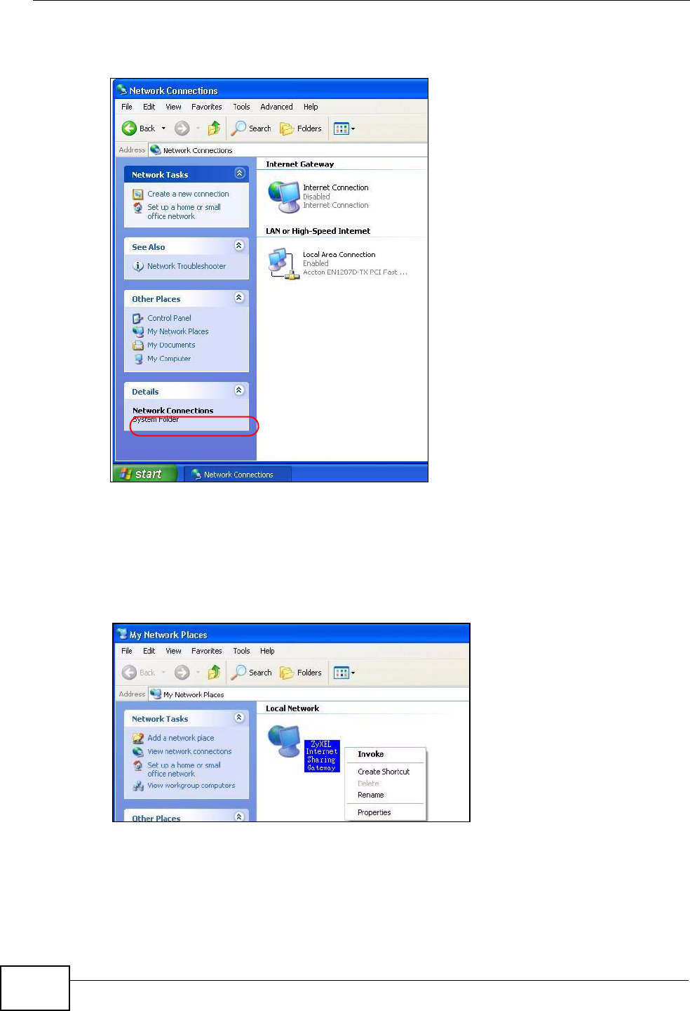
Chapter 27 Universal Plug-and-Play (UPnP)
NBG4615 User’s Guide
222
3Select My Network Places under Other Places.
Figure 130 Network Connections
4An icon with the description for each UPnP-enabled device displays under Local
Network.
5Right-click on the icon for your NBG4615 and select Invoke. The web configurator
login screen displays.
Figure 131 Network Connections: My Network Places
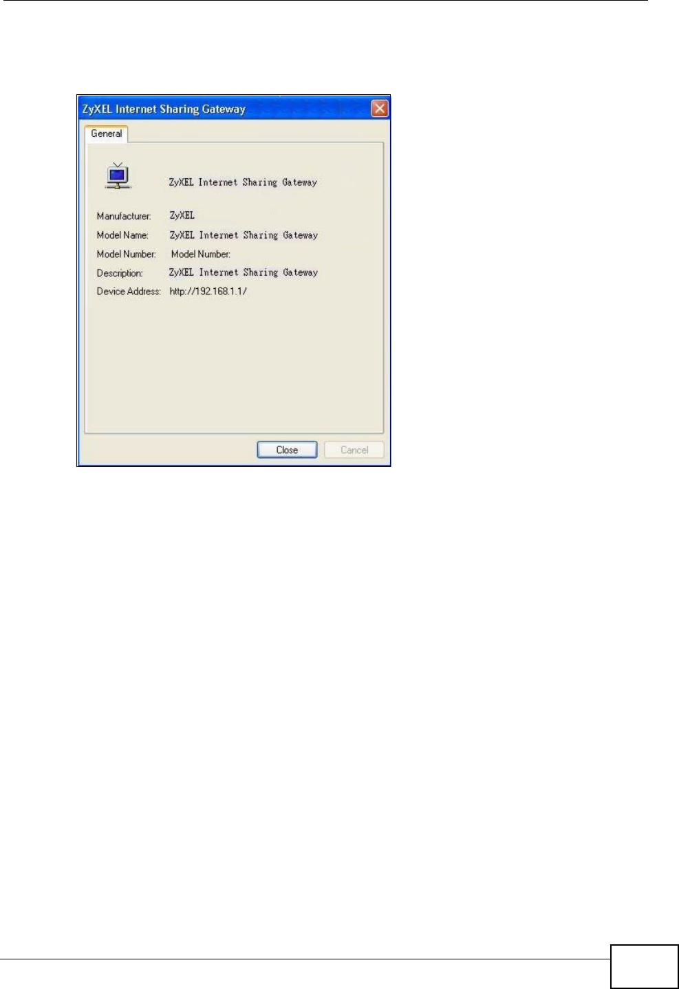
Chapter 27 Universal Plug-and-Play (UPnP)
NBG4615 User’s Guide 223
6Right-click on the icon for your NBG4615 and select Properties. A properties
window displays with basic information about the NBG4615.
Figure 132 Network Connections: My Network Places: Properties: Example

Chapter 27 Universal Plug-and-Play (UPnP)
NBG4615 User’s Guide
224

NBG4615 User’s Guide 225
CHAPTER 28
Maintenance
28.1 Overview
This chapter provides information on the Maintenance screens.
28.2 What You Can Do
•Use the General screen to set the timeout period of the management session
(Section 28.3 on page 226).
•Use the Password screen to change your NBG4615’s system password (Section
28.4 on page 226).
•Use the Time screen to change your NBG4615’s time and date (Section 28.5 on
page 228).
•Use the Firmware Upgrade screen to upload firmware to your NBG4615
(Section 28.6 on page 230).
•Use the Backup/Restore screen to view information related to factory
defaults, backup configuration, and restoring configuration (Section 28.8 on
page 233).
•Use the Reset/Restart screen to reboot the NBG4615 without turning the
power off (Section 28.8 on page 233).
•Use the Sys OP Mode screen to select how you want to use your NBG4615
(Section 28.10 on page 236).
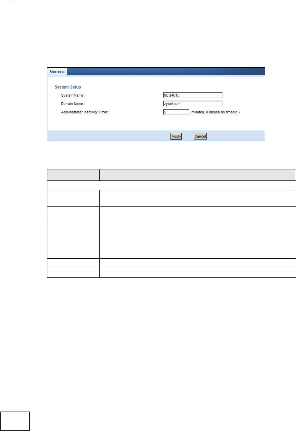
Chapter 28 Maintenance
NBG4615 User’s Guide
226
28.3 General Screen
Use this screen to set the management session timeout period. Click
Maintenance > General. The following screen displays.
Figure 133 Maintenance > General
The following table describes the labels in this screen.
28.4 Password Screen
It is strongly recommended that you change your NBG4615's password.
If you forget your NBG4615's password (or IP address), you will need to reset the
device. See Section 28.8 on page 233 for details.
Table 81 Maintenance > General
LABEL DESCRIPTION
System Setup
System Name System Name is a unique name to identify the NBG4615 in an
Ethernet network.
Domain Name Enter the domain name you want to give to the NBG4615.
Administrator
Inactivity Timer Type how many minutes a management session can be left idle before
the session times out. The default is 5 minutes. After it times out you
have to log in with your password again. Very long idle timeouts may
have security risks. A value of "0" means a management session never
times out, no matter how long it has been left idle (not
recommended).
Apply Click Apply to save your changes back to the NBG4615.
Cancel Click Cancel to begin configuring this screen afresh.
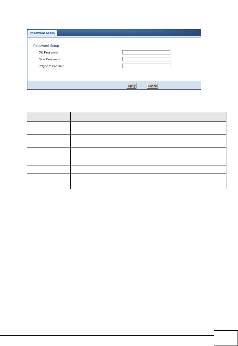
Chapter 28 Maintenance
NBG4615 User’s Guide 227
Click Maintenance > Password. The screen appears as shown.
Figure 134 Maintenance > Password
The following table describes the labels in this screen.
Table 82 Maintenance > Password
LABEL DESCRIPTION
Password Setup Change your NBG4615’s password (recommended) using the fields as
shown.
Old Password Type the default password or the existing password you use to access
the system in this field.
New Password Type your new system password (up to 30 characters). Note that as
you type a password, the screen displays an asterisk (*) for each
character you type.
Retype to Confirm Type the new password again in this field.
Apply Click Apply to save your changes back to the NBG4615.
Cancel Click Cancel to begin configuring this screen afresh.
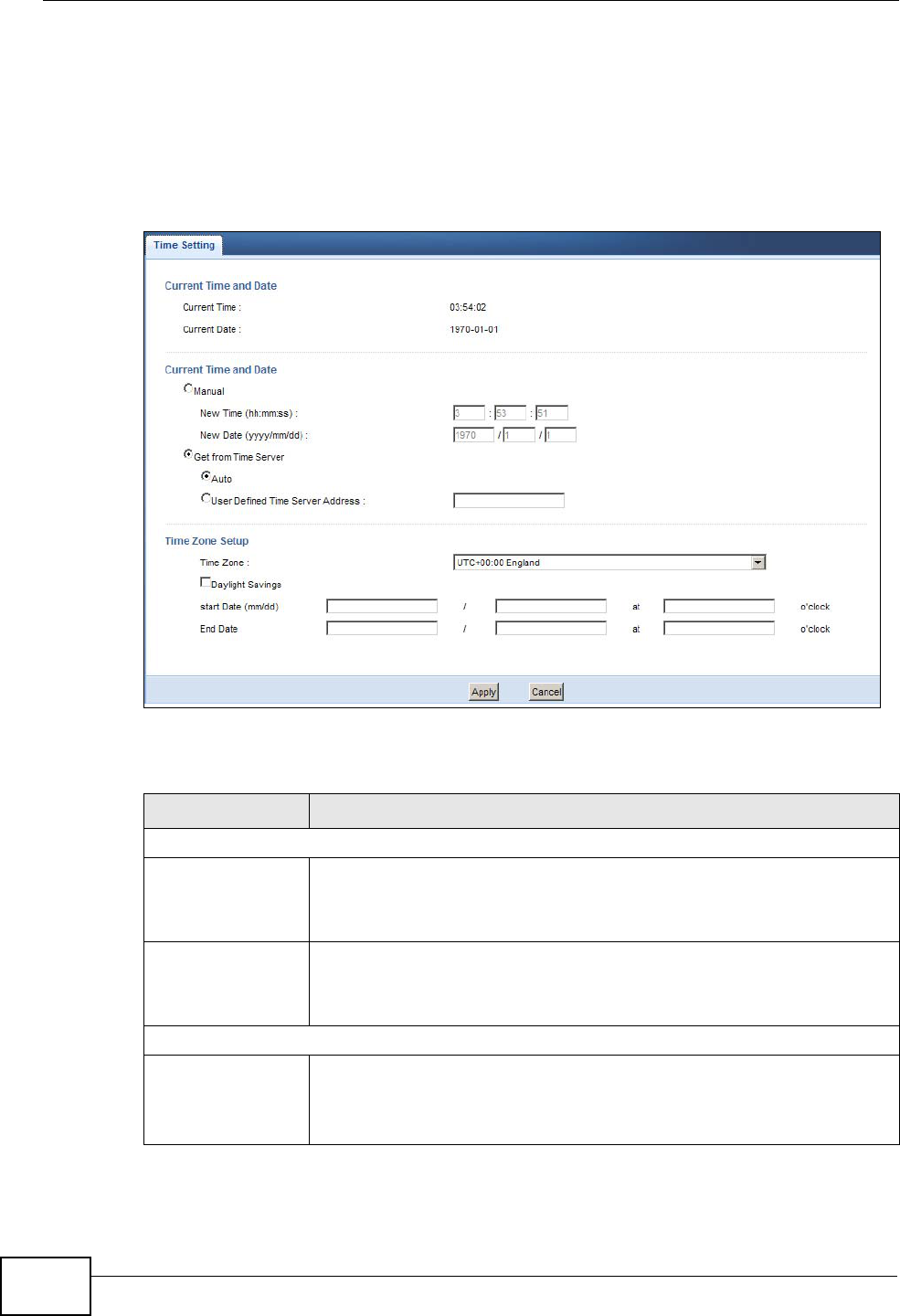
Chapter 28 Maintenance
NBG4615 User’s Guide
228
28.5 Time Setting Screen
Use this screen to configure the NBG4615’s time based on your local time zone. To
change your NBG4615’s time and date, click Maintenance > Time. The screen
appears as shown.
Figure 135 Maintenance > Time
The following table describes the labels in this screen.
Table 83 Maintenance > Time
LABEL DESCRIPTION
Current Time and Date
Current Time This field displays the time of your NBG4615.
Each time you reload this page, the NBG4615 synchronizes the time
with the time server.
Current Date This field displays the date of your NBG4615.
Each time you reload this page, the NBG4615 synchronizes the date
with the time server.
Current Time and Date
Manual Select this radio button to enter the time and date manually. If you
configure a new time and date, Time Zone and Daylight Saving at the
same time, the new time and date you entered has priority and the
Time Zone and Daylight Saving settings do not affect it.

Chapter 28 Maintenance
NBG4615 User’s Guide 229
New Time
(hh:mm:ss)
This field displays the last updated time from the time server or the
last time configured manually.
When you select Manual, enter the new time in this field and then
click Apply.
New Date
(yyyy/mm/dd)
This field displays the last updated date from the time server or the
last date configured manually.
When you select Manual, enter the new date in this field and then
click Apply.
Get from Time
Server Select this radio button to have the NBG4615 get the time and date
from the time server you specified below.
Auto Select Auto to have the NBG4615 automatically search for an
available time server and synchronize the date and time with the time
server after you click Apply.
User Defined
Time Server
Address
Select User Defined Time Server Address and enter the IP
address or URL (up to 20 extended ASCII characters in length) of
your time server. Check with your ISP/network administrator if you
are unsure of this information.
Time Zone Setup
Time Zone Choose the time zone of your location. This will set the time
difference between your time zone and Greenwich Mean Time (GMT).
Daylight Savings Daylight saving is a period from late spring to early fall when many
countries set their clocks ahead of normal local time by one hour to
give more daytime light in the evening.
Select this option if you use Daylight Saving Time.
Start Date Configure the day and time when Daylight Saving Time starts if you
selected Daylight Savings. The o'clock field uses the 24 hour
format. Here are a couple of examples:
Daylight Saving Time starts in most parts of the United States on the
first Sunday of April. Each time zone in the United States starts using
Daylight Saving Time at 2 A.M. local time. So in the United States you
would select First, Sunday, April and type 2 in the o'clock field.
Daylight Saving Time starts in the European Union on the last Sunday
of March. All of the time zones in the European Union start using
Daylight Saving Time at the same moment (1 A.M. GMT or UTC). So
in the European Union you would select Last, Sunday, March. The
time you type in the o'clock field depends on your time zone. In
Germany for instance, you would type 2 because Germany's time
zone is one hour ahead of GMT or UTC (GMT+1).
Table 83 Maintenance > Time (continued)
LABEL DESCRIPTION
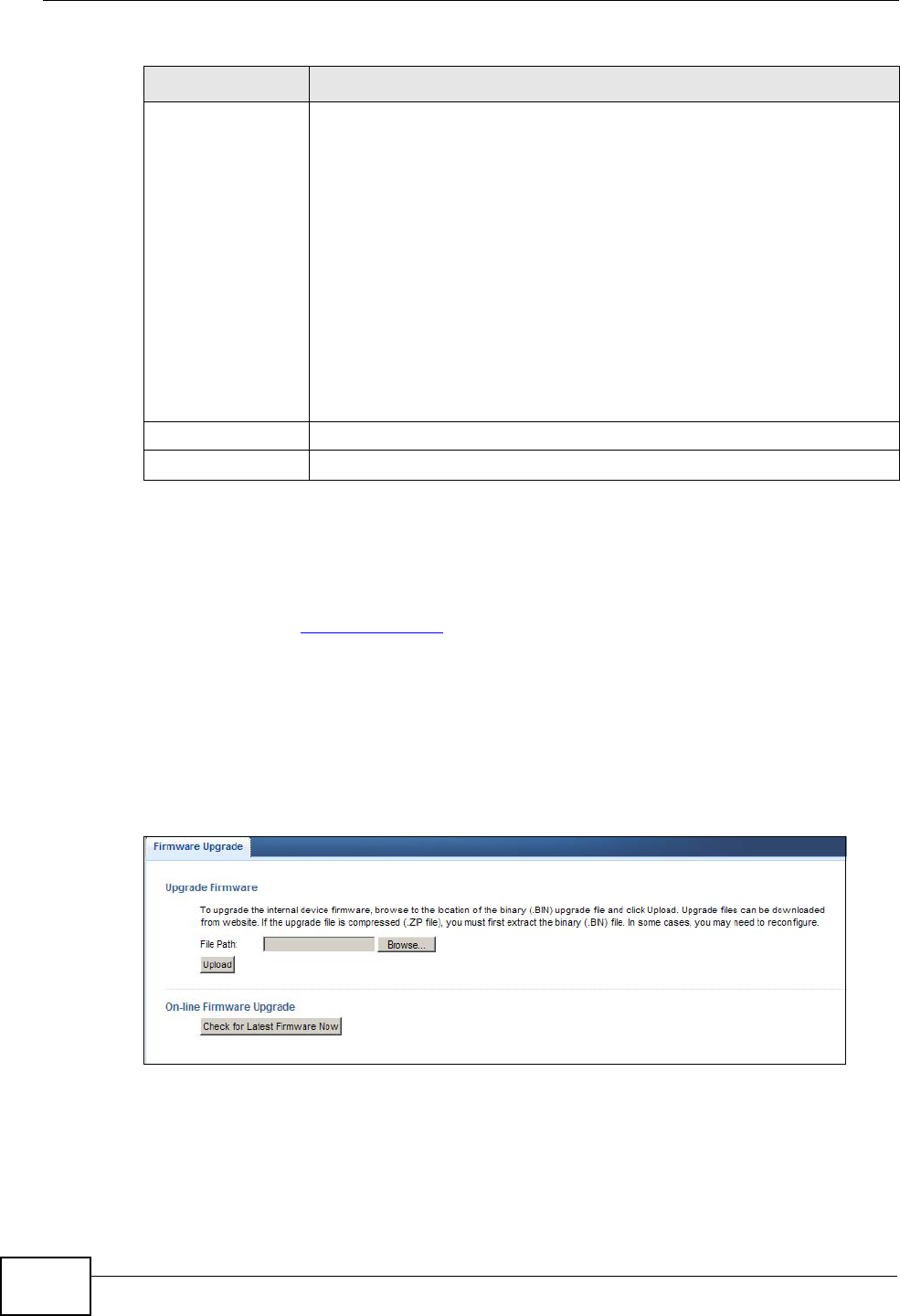
Chapter 28 Maintenance
NBG4615 User’s Guide
230
28.6 Firmware Upgrade Screen
Find firmware at www.zyxel.com in a file that (usually) uses the system model
name with a “*.bin” extension, e.g., “NBG4615.bin”. The upload process uses
HTTP (Hypertext Transfer Protocol) and may take up to two minutes. After a
successful upload, the system will reboot.
Click Maintenance > Firmware Upgrade. Follow the instructions in this screen
to upload firmware to your NBG4615.
Figure 136 Maintenance > Firmware Upgrade
End Date Configure the day and time when Daylight Saving Time ends if you
selected Daylight Savings. The o'clock field uses the 24 hour
format. Here are a couple of examples:
Daylight Saving Time ends in the United States on the last Sunday of
October. Each time zone in the United States stops using Daylight
Saving Time at 2 A.M. local time. So in the United States you would
select Last, Sunday, October and type 2 in the o'clock field.
Daylight Saving Time ends in the European Union on the last Sunday
of October. All of the time zones in the European Union stop using
Daylight Saving Time at the same moment (1 A.M. GMT or UTC). So
in the European Union you would select Last, Sunday, October. The
time you type in the o'clock field depends on your time zone. In
Germany for instance, you would type 2 because Germany's time
zone is one hour ahead of GMT or UTC (GMT+1).
Apply Click Apply to save your changes back to the NBG4615.
Cancel Click Cancel to begin configuring this screen afresh.
Table 83 Maintenance > Time (continued)
LABEL DESCRIPTION
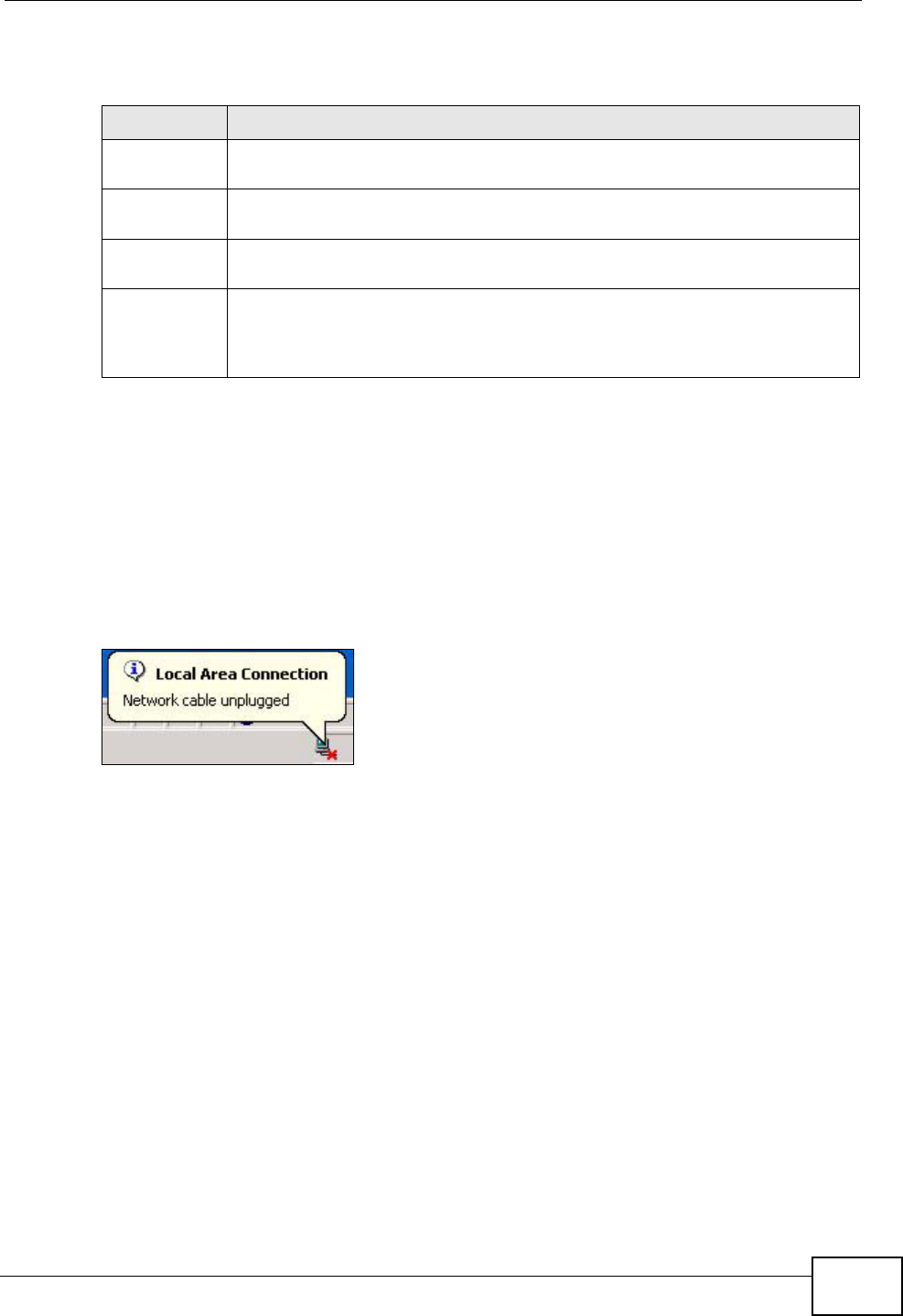
Chapter 28 Maintenance
NBG4615 User’s Guide 231
The following table describes the labels in this screen.
Note: Do not turn off the NBG4615 while firmware upload is in progress!
After you see the Firmware Upload In Process screen, wait two minutes before
logging into the NBG4615 again.
The NBG4615 automatically restarts in this time causing a temporary network
disconnect. In some operating systems, you may see the following icon on your
desktop.
Figure 137 Network Temporarily Disconnected
After two minutes, log in again and check your new firmware version in the
Status screen.
If the upload was not successful, an error message appears. Click Return to go
back to the Firmware Upgrade screen.
28.7 Configuration Backup/Restore Screen
Backup configuration allows you to back up (save) the NBG4615’s current
configuration to a file on your computer. Once your NBG4615 is configured and
functioning properly, it is highly recommended that you back up your configuration
file before making configuration changes. The backup configuration file will be
useful in case you need to return to your previous settings.
Table 84 Maintenance > Firmware Upgrade
LABEL DESCRIPTION
File Path Type in the location of the file you want to upload in this field or click
Browse... to find it.
Browse... Click Browse... to find the .bin file you want to upload. Remember that
you must decompress compressed (.zip) files before you can upload them.
Upload Click Upload to begin the upload process. This process may take up to
two minutes.
Check for
Latest
Firmware
Now
Click this to check for the latest updated firmware.
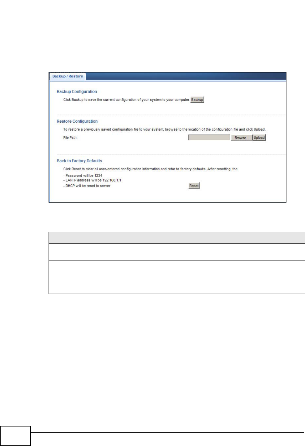
Chapter 28 Maintenance
NBG4615 User’s Guide
232
Restore configuration allows you to upload a new or previously saved
configuration file from your computer to your NBG4615.
Click Maintenance > Backup/Restore. Information related to factory defaults,
backup configuration, and restoring configuration appears as shown next.
Figure 138 Maintenance > Backup/Restore
The following table describes the labels in this screen.
Table 85 Maintenance > Backup/Restore
LABEL DESCRIPTION
Backup Click Backup to save the NBG4615’s current configuration to your
computer.
File Path Type in the location of the file you want to upload in this field or click
Browse... to find it.
Browse... Click Browse... to find the file you want to upload. Remember that you
must decompress compressed (.ZIP) files before you can upload them.
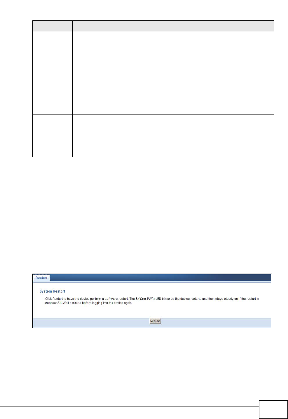
Chapter 28 Maintenance
NBG4615 User’s Guide 233
Note: If you uploaded the default configuration file you may need to change the IP
address of your computer to be in the same subnet as that of the default
NBG4615 IP address (192.168.1.2). See Appendix D on page 277 for details on
how to set up your computer’s IP address.
28.8 Reset/Restart Screen
System restart allows you to reboot the NBG4615 without turning the power off.
Click Maintenance > Reset/Restart to open the following screen.
Figure 139 Maintenance > Reset/Restart
Click Restart to have the NBG4615 reboot. This does not affect the NBG4615's
configuration.
Upload Click Upload to begin the upload process.
Note: Do not turn off the NBG4615 while configuration file upload is in
progress.
After you see a “configuration upload successful” screen, you must then
wait one minute before logging into the NBG4615 again. The NBG4615
automatically restarts in this time causing a temporary network
disconnect.
If you see an error screen, click Back to return to the Backup/Restore
screen.
Reset Pressing the Reset button in this section clears all user-entered
configuration information and returns the NBG4615 to its factory defaults.
You can also press the RESET button on the rear panel to reset the factory
defaults of your NBG4615. Refer to the chapter about introducing the Web
Configurator for more information on the RESET button.
Table 85 Maintenance > Backup/Restore (continued)
LABEL DESCRIPTION
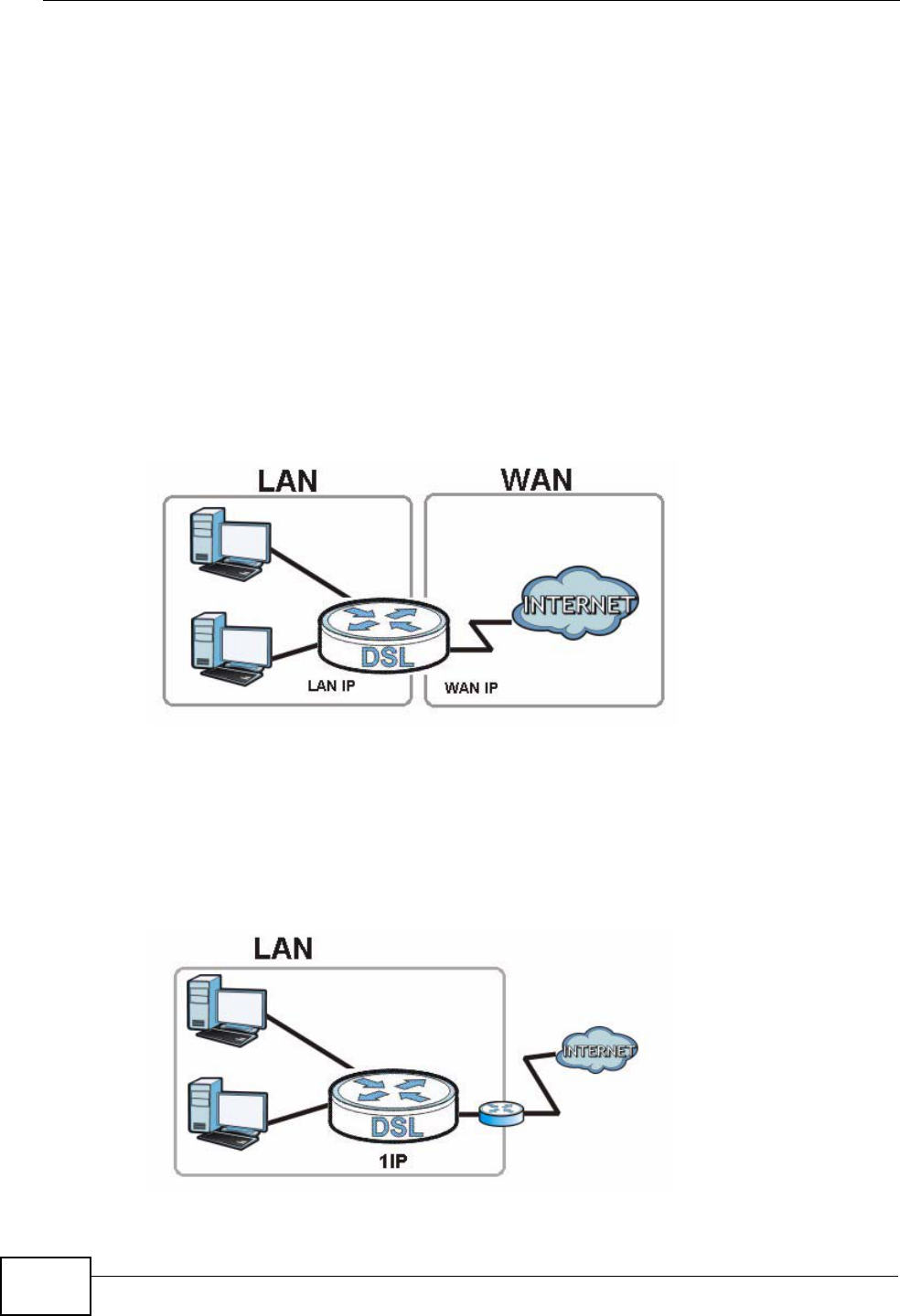
Chapter 28 Maintenance
NBG4615 User’s Guide
234
28.9 System Operation Mode Overview
The Sys OP Mode (System Operation Mode) function lets you configure your
NBG4615 as an access point, wireless client or both at the same time. You can
choose between Router, Access Point Mode, Universal Repeater Mode, and
WISP Mode depending on your network topology and the features you require
from your device.
The following describes the device modes available in your NBG4615.
Router
A router connects your local network with another network, such as the Internet.
The router has two IP addresses, the LAN IP address and the WAN IP address.
Figure 140 LAN and WAN IP Addresses in Router Mode
Access Point
An access point enabled all ethernet ports to be bridged together and be in the
same subnet. To connect to the Internet, another device, such as a router, is
required.
Figure 141 Access Point Mode
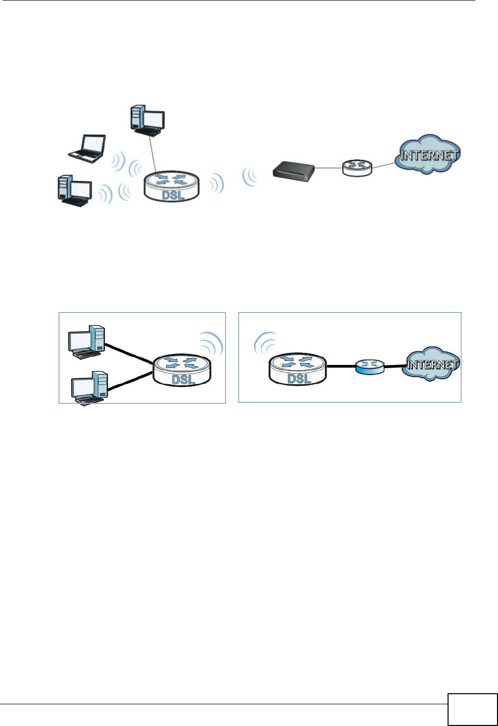
Chapter 28 Maintenance
NBG4615 User’s Guide 235
Universal Repeater
NBG4615 in Universal Repeater mode work as an access point and wireless client
simultaneously.
Figure 142 Universal Repeater Mode
WISP
A WISP client connects to an existing access point wirelessly. It acts just like a
wireless client in notebooks/computers.
Figure 143 IP Address in Access Point Mode
Access Point
Wireless Client
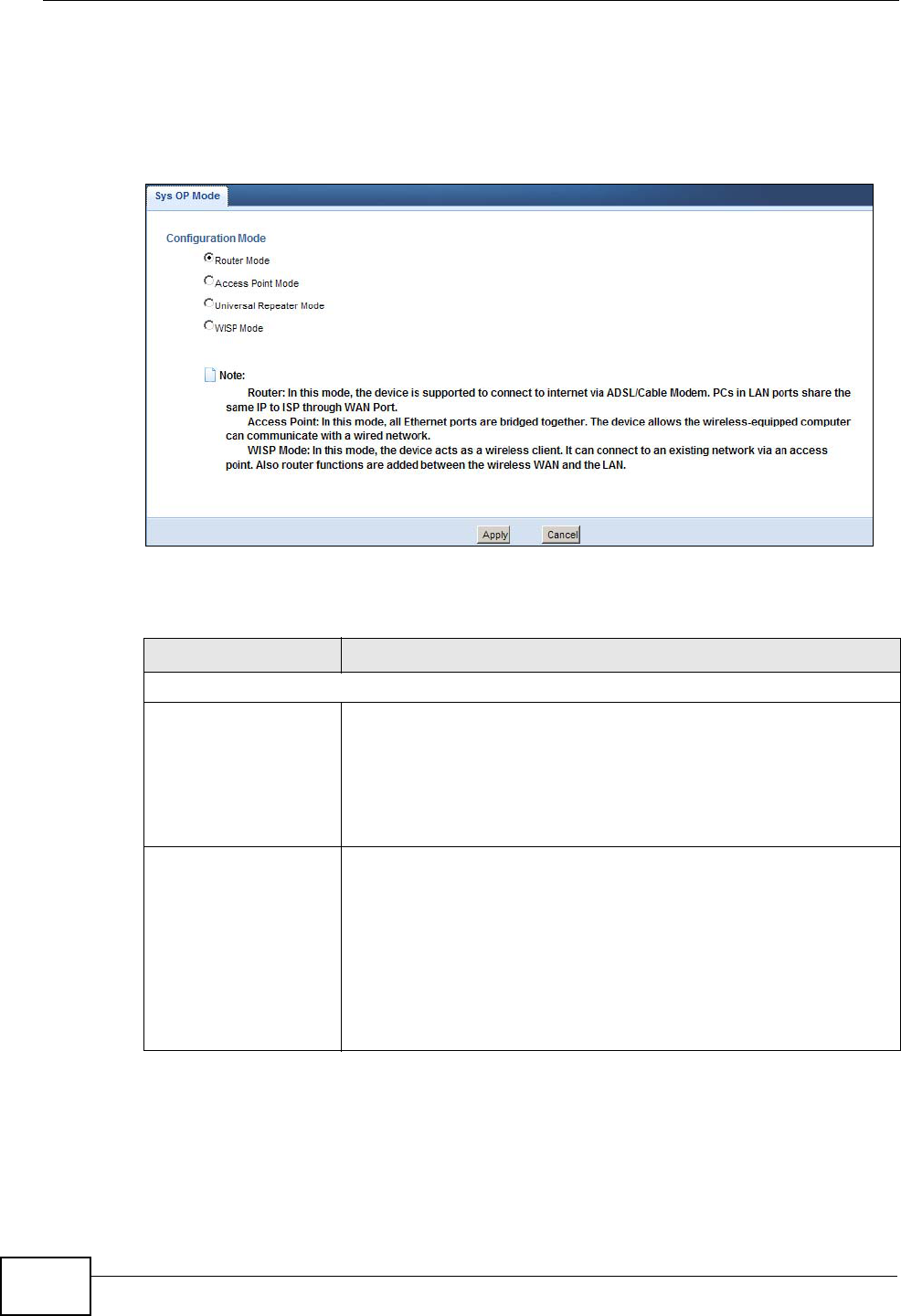
Chapter 28 Maintenance
NBG4615 User’s Guide
236
28.10 Sys OP Mode Screen
Use this screen to select how you want to use your NBG4615.
Figure 144 Maintenance > Sys OP Mode
The following table describes the labels in the General screen.
Table 86 Maintenance > Sys OP Mode
LABEL DESCRIPTION
System Operation Mode
Router Select Router Mode if your device routes traffic between a local
network and another network such as the Internet. This mode
offers services such as a firewall or bandwidth management.
You can configure the IP address settings on your WAN port.
Contact your ISP or system administrator for more information on
appropriate settings.
Access Point Select Access Point Mode if your device bridges traffic between
clients on the same network.
•In Access Point Mode, all Ethernet ports have the same IP
address.
• All ports on the rear panel of the device are LAN ports,
including the port labeled WAN. There is no WAN port.
• The DHCP server on your device is disabled.
• The IP address of the device on the local network is set to
192.168.1.2.

Chapter 28 Maintenance
NBG4615 User’s Guide 237
Note: If you select the incorrect System Operation Mode you may not be able to
connect to the Internet.
Universal Repeater
Mode Select Universal Repeater Mode if you want to have wireless
clients associate with the NBG4615 and also want to connect the
NBG4615 to an existing access point.
• In addition to wireless LAN settings between the NBG4615 and
wireless clients, you also need to configure security and
wireless settings between the NBG4615 and another access
point.
• WDS is not available when the NBG4615 is in Universal
Repeater Mode.
• The IP address of the device on the local network is the same
as the IP address given to the NBG4615 while in Access Point
Mode (default is 192.168.1.2).
WISP Mode Select WISP Mode if your device needs a wireless client to
connect to an existing access point.
• You cannot configure Wireless LAN settings (including WPS)
and scheduling in the WISP Mode.
• The IP address of the device on the local network is the same
as the IP address given to the NBG4615 while in router mode
(default is 192.168.1.1).
Apply Click Apply to save your settings.
Cancel Click Cancel to return your settings to the default (Router).
Table 86 Maintenance > Sys OP Mode (continued)
LABEL DESCRIPTION

Chapter 28 Maintenance
NBG4615 User’s Guide
238

NBG4615 User’s Guide 239
CHAPTER 29
Troubleshooting
29.1 Overview
This chapter offers some suggestions to solve problems you might encounter. The
potential problems are divided into the following categories.
•Power, Hardware Connections, and LEDs
•NBG4615 Access and Login
•Internet Access
•Resetting the NBG4615 to Its Factory Defaults
•Wireless Router/AP Troubleshooting
•ZyXEL Share Center Utility Problems
29.2 Power, Hardware Connections, and LEDs
The NBG4615 does not turn on. None of the LEDs turn on.
1Make sure you are using the power adaptor or cord included with the NBG4615.
2Make sure the power adaptor or cord is connected to the NBG4615 and plugged in
to an appropriate power source. Make sure the power source is turned on.
3Disconnect and re-connect the power adaptor or cord to the NBG4615.
4If the problem continues, contact the vendor.
One of the LEDs does not behave as expected.

Chapter 29 Troubleshooting
NBG4615 User’s Guide
240
1Make sure you understand the normal behavior of the LED. See Section 1.5 on
page 22.
2Check the hardware connections. See the Quick Start Guide.
3Inspect your cables for damage. Contact the vendor to replace any damaged
cables.
4Disconnect and re-connect the power adaptor to the NBG4615.
5If the problem continues, contact the vendor.
29.3 NBG4615 Access and Login
I don’t know the IP address of my NBG4615.
1The default IP address is 192.168.1.1.
2If you changed the IP address and have forgotten it, you might get the IP address
of the NBG4615 by looking up the IP address of the default gateway for your
computer. To do this in most Windows computers, click Start > Run, enter cmd,
and then enter ipconfig. The IP address of the Default Gateway might be the IP
address of the NBG4615 (it depends on the network), so enter this IP address in
your Internet browser.Set your device to Router Mode, login (see the Quick Start
Guide for instructions) and go to the Device Information table in the Status
screen. Your NBG4615’s IP address is available in the Device Information table.
•If the DHCP setting under LAN information is None, your device has a fixed
IP address.
•If the DHCP setting under LAN information is Client, then your device
receives an IP address from a DHCP server on the network.
3If your NBG4615 is a DHCP client, you can find your IP address from the DHCP
server. This information is only available from the DHCP server which allocates IP
addresses on your network. Find this information directly from the DHCP server or
contact your system administrator for more information.
4Reset your NBG4615 to change all settings back to their default. This means your
current settings are lost. See Section 29.5 on page 244 in the Troubleshooting
for information on resetting your NBG4615.

Chapter 29 Troubleshooting
NBG4615 User’s Guide 241
I forgot the password.
1The default password is 1234.
2If this does not work, you have to reset the device to its factory defaults. See
Section 29.5 on page 244.
I cannot see or access the Login screen in the Web Configurator.
1Make sure you are using the correct IP address.
• The default IP address is 192.168.1.1.
• If you changed the IP address (Section 7.3 on page 102), use the new IP
address.
• If you changed the IP address and have forgotten it, see the troubleshooting
suggestions for I don’t know the IP address of my NBG4615.
2Check the hardware connections, and make sure the LEDs are behaving as
expected. See the Quick Start Guide.
3Make sure your Internet browser does not block pop-up windows and has
JavaScript and Java enabled. See Appendix B on page 253.
4Make sure your computer is in the same subnet as the NBG4615. (If you know
that there are routers between your computer and the NBG4615, skip this step.)
• If there is a DHCP server on your network, make sure your computer is using
a dynamic IP address. See Section 7.3 on page 102.
• If there is no DHCP server on your network, make sure your computer’s IP
address is in the same subnet as the NBG4615. See Section 7.3 on page 102.
5Reset the device to its factory defaults, and try to access the NBG4615 with the
default IP address. See Section 7.3 on page 102.
6If the problem continues, contact the network administrator or vendor, or try one
of the advanced suggestions.
Advanced Suggestions
• Try to access the NBG4615 using another service, such as Telnet. If you can
access the NBG4615, check the remote management settings and firewall rules
to find out why the NBG4615 does not respond to HTTP.

Chapter 29 Troubleshooting
NBG4615 User’s Guide
242
• If your computer is connected to the WAN port or is connected wirelessly, use a
computer that is connected to a LAN/ETHERNET port.
I can see the Login screen, but I cannot log in to the NBG4615.
1Make sure you have entered the password correctly. The default password is
1234. This field is case-sensitive, so make sure [Caps Lock] is not on.
2You cannot log in to the Web Configurator while someone is using Telnet to access
the NBG4615. Log out of the NBG4615 in the other session, or ask the person who
is logged in to log out.
3This can happen when you fail to log out properly from your last session. Try
logging in again after 5 minutes.
4Disconnect and re-connect the power adaptor or cord to the NBG4615.
5If this does not work, you have to reset the device to its factory defaults. See
Section 29.5 on page 244.
29.4 Internet Access
I cannot access the Internet.
1Check the hardware connections, and make sure the LEDs are behaving as
expected. See the Quick Start Guide.
2Make sure you entered your ISP account information correctly in the wizard. These
fields are case-sensitive, so make sure [Caps Lock] is not on.
3If you are trying to access the Internet wirelessly, make sure the wireless settings
in the wireless client are the same as the settings in the AP.
• Go to Network > Wireless LAN > General > WDS and check if the NBG4615 is
set to bridge mode. Select Disable and try to connect to the Internet again.
4Disconnect all the cables from your device, and follow the directions in the Quick
Start Guide again.
5Go to Maintenance > Sys OP Mode > General. Check your System Operation Mode
setting.

Chapter 29 Troubleshooting
NBG4615 User’s Guide 243
• Select Router if your device routes traffic between a local network and
another network such as the Internet.
• Select Access Point if your device bridges traffic between clients on the
same network.
6If the problem continues, contact your ISP.
I cannot access the Internet anymore. I had access to the Internet (with the
NBG4615), but my Internet connection is not available anymore.
1Check the hardware connections, and make sure the LEDs are behaving as
expected. See the Quick Start Guide and Section 1.5 on page 22.
2Reboot the NBG4615.
3If the problem continues, contact your ISP.
The Internet connection is slow or intermittent.
1There might be a lot of traffic on the network. Look at the LEDs, and check Section
1.5 on page 22. If the NBG4615 is sending or receiving a lot of information, try
closing some programs that use the Internet, especially peer-to-peer applications.
2Check the signal strength. If the signal strength is low, try moving the NBG4615
closer to the AP if possible, and look around to see if there are any devices that
might be interfering with the wireless network (for example, microwaves, other
wireless networks, and so on).
3Reboot the NBG4615.
4If the problem continues, contact the network administrator or vendor, or try one
of the advanced suggestions.
Advanced Suggestion
• Check the settings for QoS. If it is disabled, you might consider activating it.

Chapter 29 Troubleshooting
NBG4615 User’s Guide
244
29.5 Resetting the NBG4615 to Its Factory
Defaults
If you reset the NBG4615, you lose all of the changes you have made. The
NBG4615 re-loads its default settings, and the password resets to 1234. You have
to make all of your changes again.
You will lose all of your changes when you push the RESET button.
To reset the NBG4615:
1Make sure the power LED is on.
2Press the RESET button for longer than 1 second to restart/reboot the NBG4615.
3Press the RESET button for longer than five seconds to set the NBG4615 back to
its factory-default configurations.
If the NBG4615 restarts automatically, wait for the NBG4615 to finish restarting,
and log in to the Web Configurator. The password is “1234”.
If the NBG4615 does not restart automatically, disconnect and reconnect the
NBG4615’s power. Then, follow the directions above again.
29.6 Wireless Router/AP Troubleshooting
I cannot access the NBG4615 or ping any computer from the WLAN (wireless AP
or router).
1Make sure the wireless LAN is enabled on the NBG4615.
2Make sure the wireless adapter on the wireless station is working properly.
3Make sure the wireless adapter installed on your computer is IEEE 802.11
compatible and supports the same wireless standard as the NBG4615.
4Make sure your computer (with a wireless adapter installed) is within the
transmission range of the NBG4615.

Chapter 29 Troubleshooting
NBG4615 User’s Guide 245
5Check that both the NBG4615 and your wireless station are using the same
wireless and wireless security settings.
6Make sure traffic between the WLAN and the LAN is not blocked by the firewall on
the NBG4615.
7Make sure you allow the NBG4615 to be remotely accessed through the WLAN
interface. Check your remote management settings.
• See the chapter on Wireless LAN in the User’s Guide for more information.
I set up URL keyword blocking, but I can still access a website that should be
blocked.
Make sure that you select the Enable URL Keyword Blocking check box in the
Content Filtering screen. Make sure that the keywords that you type are listed in
the Keyword List.
If a keyword that is listed in the Keyword List is not blocked when it is found in a
URL, customize the keyword blocking using commands. See the Customizing
Keyword Blocking URL Checking section in the Content Filtering chapter.
I can access the Internet, but I cannot open my network folders.
In the Network > LAN > Advanced screen, make sure Allow between LAN
and WAN is checked. This is not checked by default to keep the LAN secure.
If you still cannot access a network folder, make sure your account has access
rights to the folder you are trying to open.
I cannot access the Web Configurator after I switched to AP mode.
When you change from router mode to AP mode, your computer must have an IP
address in the range between “192.168.1.3” and “192.168.1.254”.
Refer to Appendix D on page 277 for instructions on how to change your
computer’s IP address.

Chapter 29 Troubleshooting
NBG4615 User’s Guide
246
What factors may cause intermittent or unstabled wireless connection? How can I
solve this problem?
The following factors may cause interference:
• Obstacles: walls, ceilings, furniture, and so on.
• Building Materials: metal doors, aluminum studs.
• Electrical devices: microwaves, monitors, electric motors, cordless phones, and
other wireless devices.
To optimize the speed and quality of your wireless connection, you can:
• Move your wireless device closer to the AP if the signal strength is low.
• Reduce wireless interference that may be caused by other wireless networks or
surrounding wireless electronics such as cordless phones.
• Place the AP where there are minimum obstacles (such as walls and ceilings)
between the AP and the wireless client.
• Reduce the number of wireless clients connecting to the same AP
simultaneously, or add additional APs if necessary.
• Try closing some programs that use the Internet, especially peer-to-peer
applications. If the wireless client is sending or receiving a lot of information, it
may have too many programs open that use the Internet.
• Position the antennas for best reception. If the AP is placed on a table or floor,
point the antennas upwards. If the AP is placed at a high position, point the
antennas downwards. Try pointing the antennas in different directions and
check which provides the strongest signal to the wireless clients.
29.7 ZyXEL Share Center Utility Problems
I cannot access or see a USB device that is connected to the NBG4615.
1Disconnect the problematic USB device, then reconnect it to the NBG4615.
2Ensure that the USB device in question has power.
3Check your cable connections.
4Restart the NBG4615 by disconnecting the power and then reconnecting it.

Chapter 29 Troubleshooting
NBG4615 User’s Guide 247
5If the USB device requires a special driver, install the driver from the installation
disc that came with the device. After driver installation, reconnect the USB device
to the NBG4615 and try to connect to it again with your computer.
6If the problem persists, contact your vendor.
I cannot install the ZyXEL Share Center Utility.
1Make sure that the set up program is one required for your operating system.
2Install the latest patches and updates for your operating system.
3Check the zyxel.com download site for a newer version of the utility.

Chapter 29 Troubleshooting
NBG4615 User’s Guide
248

NBG4615 User’s Guide 249
APPENDIX A
Product Specifications
The following tables summarize the NBG4615’s hardware and firmware features.
Table 87 Hardware Features
Dimensions 162 mm (W) x 106 mm (D) x 28 mm (H)
Weight 285g
SDRAM 32 MB
Flash Memory 8 MB
Power Specification Input: 100~240 AC, 50~60 Hz
Output: 12 V DC 1.5A
Ethernet ports Auto-negotiating: 100 Mbps, 1000 Mbps in either half-duplex or
full-duplex mode.
Auto-crossover: Use either crossover or straight-through Ethernet
cables.
Built-in Switch A combination of switch and router makes your NBG4615 a cost-
effective and viable network solution. You can add up to two
computers to the NBG4615 without the cost of a hub when
connecting to the Internet through the WAN port. You can add up
to three computers to the NBG4615 when you connect to the
Internet in AP mode. Add more than four computers to your LAN
by using a hub.
LEDs Power, LAN1-4, WAN, Internet/WPS, USB1-2
Reset button The reset button is built into the rear panel. Use this button to
restore the NBG4615 to its factory default settings. Press for 1
second to restart the device. Press for 5 seconds to restore to
factory default settings.
WPS button Press the WPS on two WPS enabled devices within 120 seconds
for a security-enabled wireless connection.
Power switch Turn on or turn off the power of the NBG4615 using this switch.
WLAN switch Turn on or turn off the wireless function of the NBG4615 using this
switch. There is no need to go into the Web Configurator.
Antenna The NBG4615 is equipped with two 2dBi (or 5dBi) detachable
antenna to provide clear radio transmission and reception on the
wireless network.
USB Port The NBG4615 has two built-in USB 2.0 type A for USB device
connectivity and supports 3G USB dongle.

Appendix A Product Specifications
NBG4615 User’s Guide
250
Operation
Environment Temperature: 0º C ~ 40º C / 32ºF ~ 104ºF
Humidity: 10% ~ 90%
Storage Environment Temperature: -30º C ~ 70º C / -22ºF ~ 158ºF
Humidity: 10% ~ 95%
Table 88 Firmware Features
FEATURE DESCRIPTION
Default LAN IP Address 192.168.1.1 (router)
192.168.1.2. (AP)
Default LAN Subnet
Mask 255.255.255.0 (24 bits)
Default Password 1234
DHCP Pool 192.168.1.33 to 192.168.1.64
Wireless Interface Wireless LAN
Default Wireless SSID ZyXEL
Device Management Use the Web Configurator to easily configure the rich range of
features on the NBG4615.
Wireless Functionality Allows IEEE 802.11b, IEEE 802.11g and/or IEEE 802.11n
wireless clients to connect to the NBG4615 wirelessly. Enable
wireless security (WPA(2)-PSK) and/or MAC filtering to protect
your wireless network.
Note: The NBG4615 may be prone to RF (Radio
Frequency) interference from other 2.4 GHz devices
such as microwave ovens, wireless phones,
Bluetooth enabled devices, and other wireless LANs.
Firmware Upgrade Download new firmware (when available) from the ZyXEL web
site and use the Web Configurator to put it on the NBG4615.
Note: Only upload firmware for your specific model!
Configuration Backup &
Restoration Make a copy of the NBG4615’s configuration and put it back on
the NBG4615 later if you decide you want to revert back to an
earlier configuration.
Network Address
Translation (NAT) Each computer on your network must have its own unique IP
address. Use NAT to convert a single public IP address to
multiple private IP addresses for the computers on your
network.
Firewall You can configure firewall on the NBG4615 for secure Internet
access. When the firewall is on, by default, all incoming traffic
from the Internet to your network is blocked unless it is
initiated from your network. This means that probes from the
outside to your network are not allowed, but you can safely
browse the Internet and download files for example.
Table 87 Hardware Features (continued)

Appendix A Product Specifications
NBG4615 User’s Guide 251
29.8 Wall-mounting Instructions
Complete the following steps to hang your NBG4615 on a wall.
1Select a position free of obstructions on a sturdy wall.
2Drill two holes for the screws.
Content Filter The NBG4615 blocks or allows access to web sites that you
specify and blocks access to web sites with URLs that contain
keywords that you specify.
Bandwidth Management You can efficiently manage traffic on your network by reserving
bandwidth and giving priority to certain types of traffic and/or
to particular computers.
Remote Management This allows you to decide whether a service (HTTP traffic for
example) from a computer on a network (LAN or WAN for
example) can access the NBG4615.
Wireless LAN Scheduler You can schedule the times the Wireless LAN is enabled/
disabled.
Time and Date Get the current time and date from an external server when
you turn on your NBG4615. You can also set the time manually.
These dates and times are then used in logs.
Port Forwarding If you have a server (mail or web server for example) on your
network, then use this feature to let people access it from the
Internet.
DHCP (Dynamic Host
Configuration Protocol) Use this feature to have the NBG4615 assign IP addresses, an
IP default gateway and DNS servers to computers on your
network.
Dynamic DNS Support With Dynamic DNS (Domain Name System) support, you can
use a fixed URL, www.zyxel.com for example, with a dynamic
IP address. You must register for this service with a Dynamic
DNS service provider.
IP Multicast IP Multicast is used to send traffic to a specific group of
computers. The NBG4615 supports versions 1 and 2 of IGMP
(Internet Group Management Protocol) used to join multicast
groups (see RFC 2236).
Logging Use logs for troubleshooting. You can view logs in the Web
Configurator.
PPPoE PPPoE mimics a dial-up Internet access connection.
PPTP Encapsulation Point-to-Point Tunneling Protocol (PPTP) enables secure
transfer of data through a Virtual Private Network (VPN). The
NBG4615 supports one PPTP connection at a time.
Universal Plug and Play
(UPnP) The NBG4615 can communicate with other UPnP enabled
devices in a network.
Table 88 Firmware Features (continued)
FEATURE DESCRIPTION
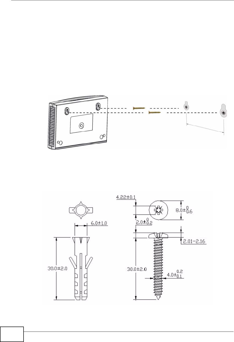
Appendix A Product Specifications
NBG4615 User’s Guide
252
Be careful to avoid damaging pipes or cables located inside the
wall when drilling holes for the screws.
3Do not insert the screws all the way into the wall. Leave a small gap of about 0.5
cm between the heads of the screws and the wall.
4Make sure the screws are snugly fastened to the wall. They need to hold the
weight of the NBG4615 with the connection cables.
5Align the holes on the back of the NBG4615 with the screws on the wall. Hang the
NBG4615 on the screws.
Figure 145 Wall-mounting Example
The following are dimensions of an M4 tap screw and masonry plug used for wall
mounting. All measurements are in millimeters (mm).
Figure 146 Masonry Plug and M4 Tap Screw