ZyXEL Communications NBG6515 AC750 Dual band Wireless Gigabit Router User Manual Book
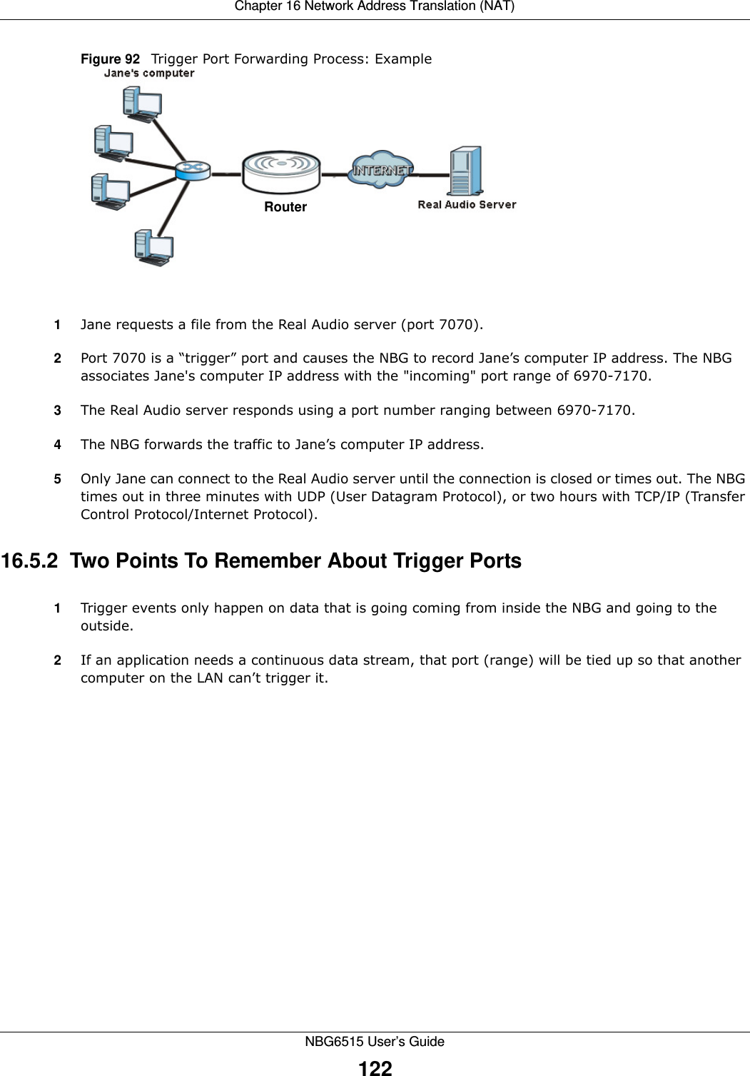
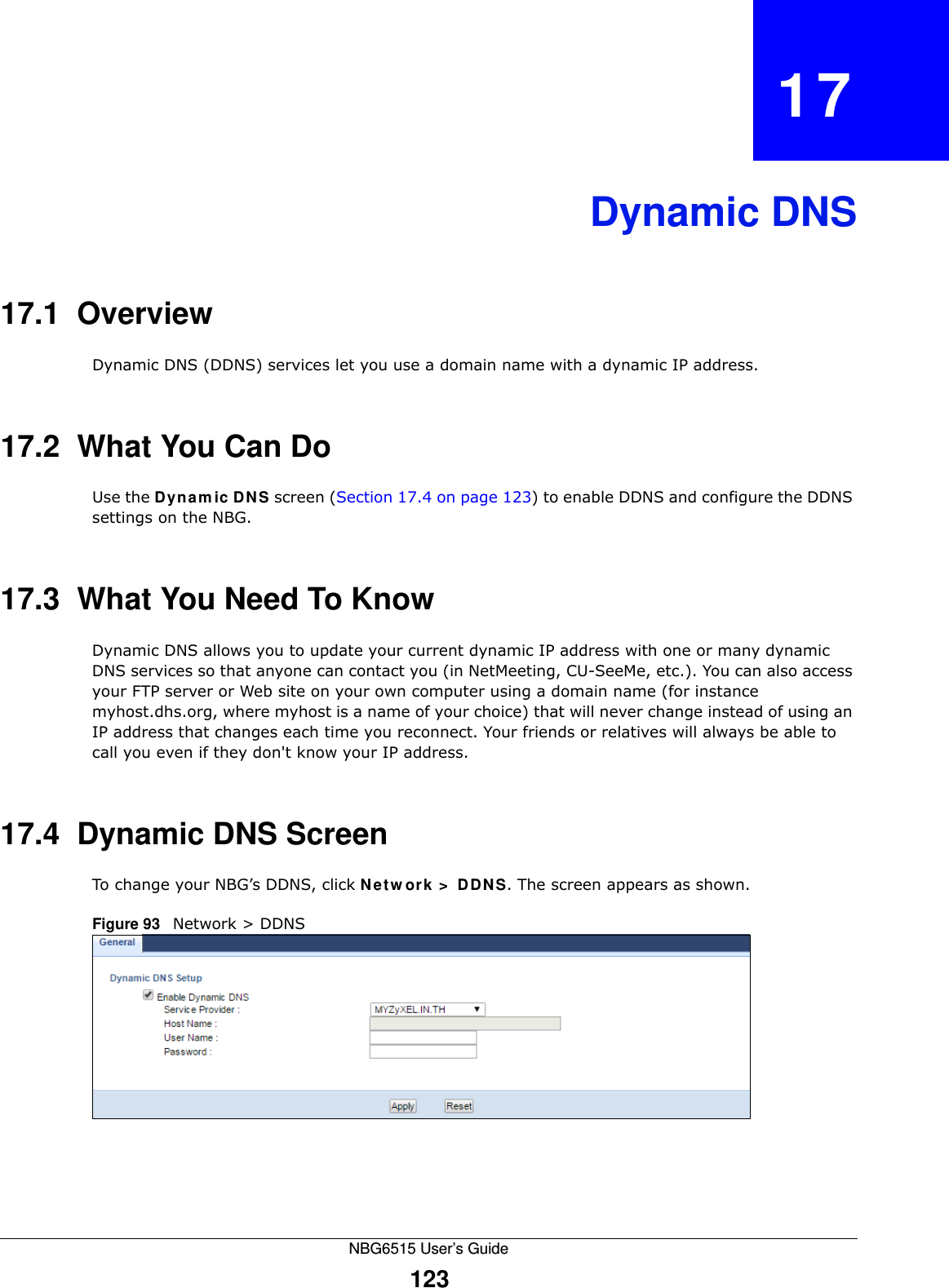
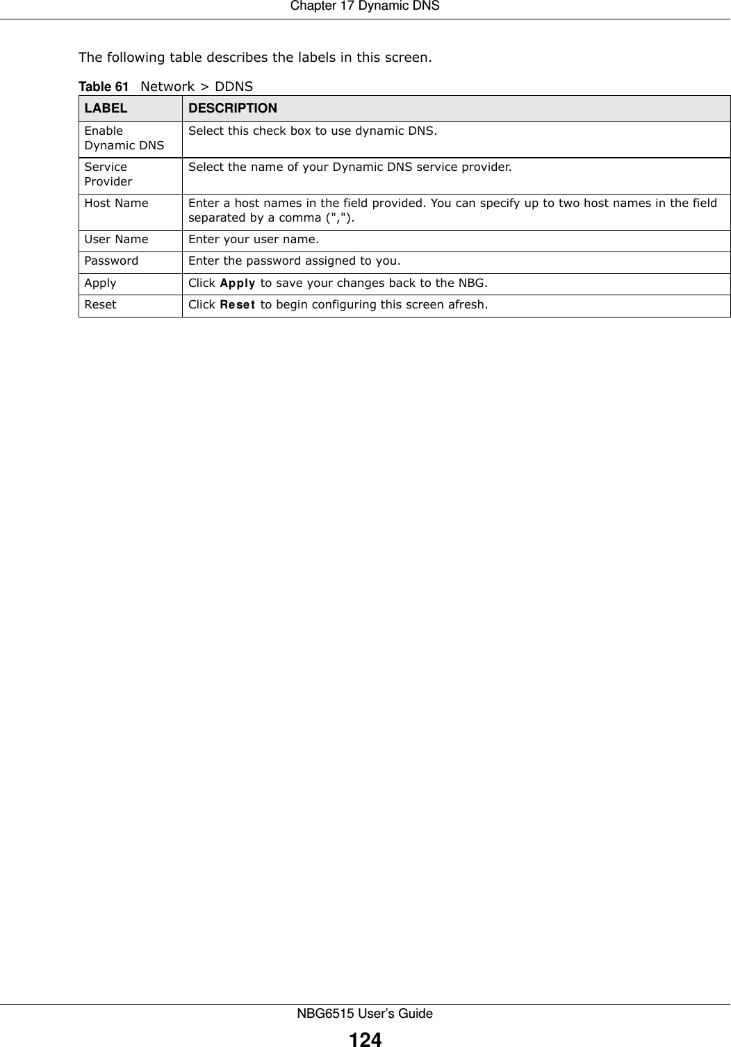
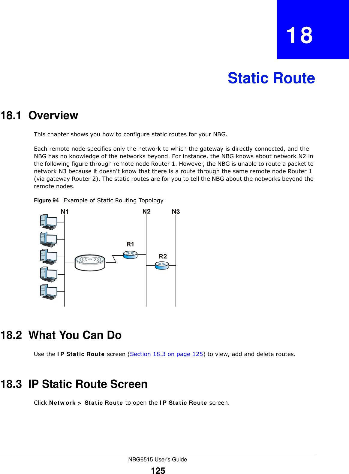
ZyXEL Communications Corporation AC750 Dual band Wireless Gigabit Router Book
UserManual.wiki
>
ZyXEL Communications
>
NBG6515 User Manual
>
Users Manual
Contents
1.
Users Manual
2.
Users Manual 2
Users Manual
Navigation menu
Upload a User Manual
Namespaces
Wiki Guide
HTML
PDF
Info
Views
User Manual
Discussion / Help
Navigation
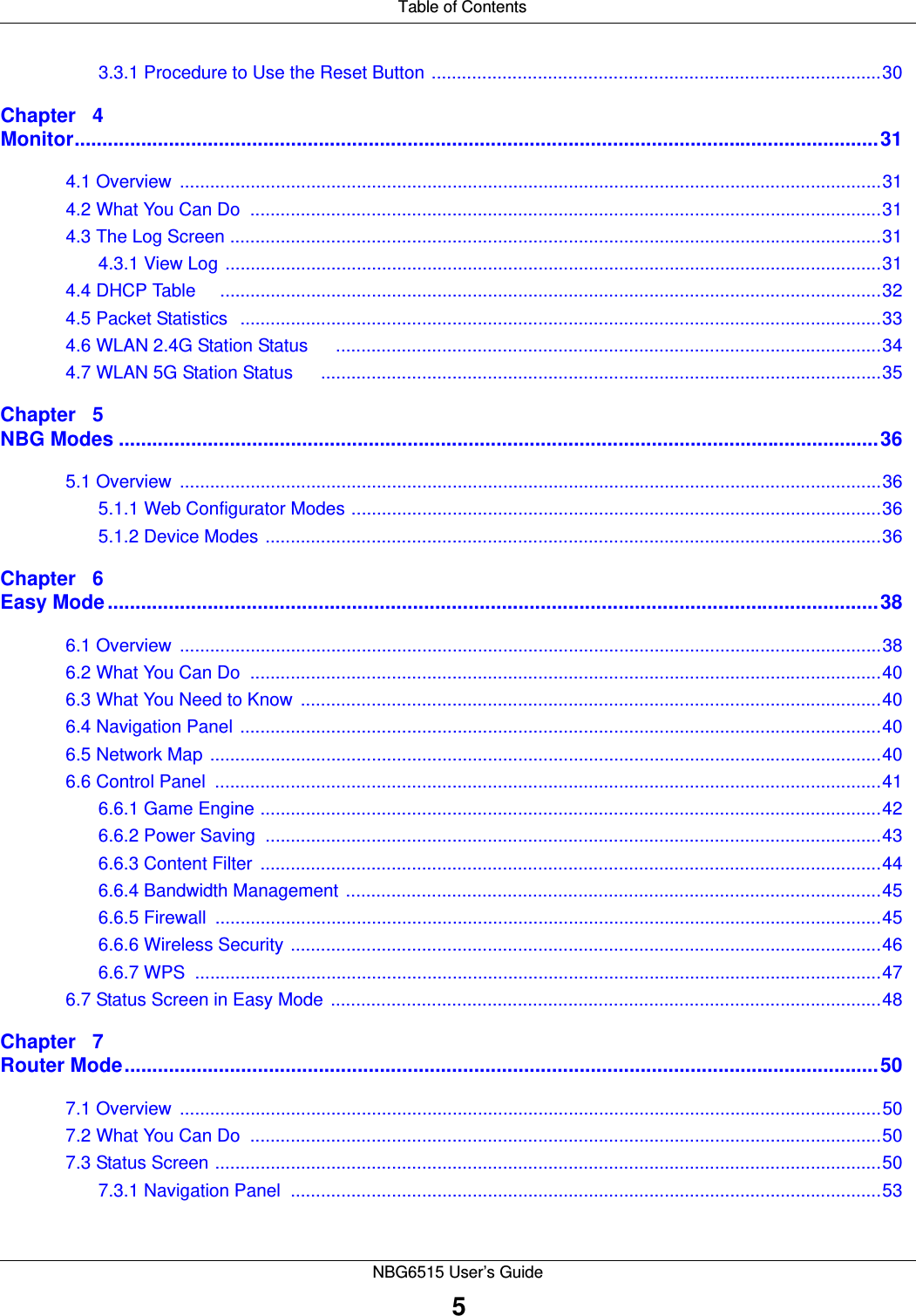
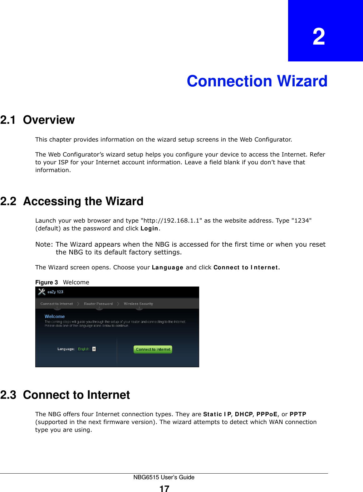
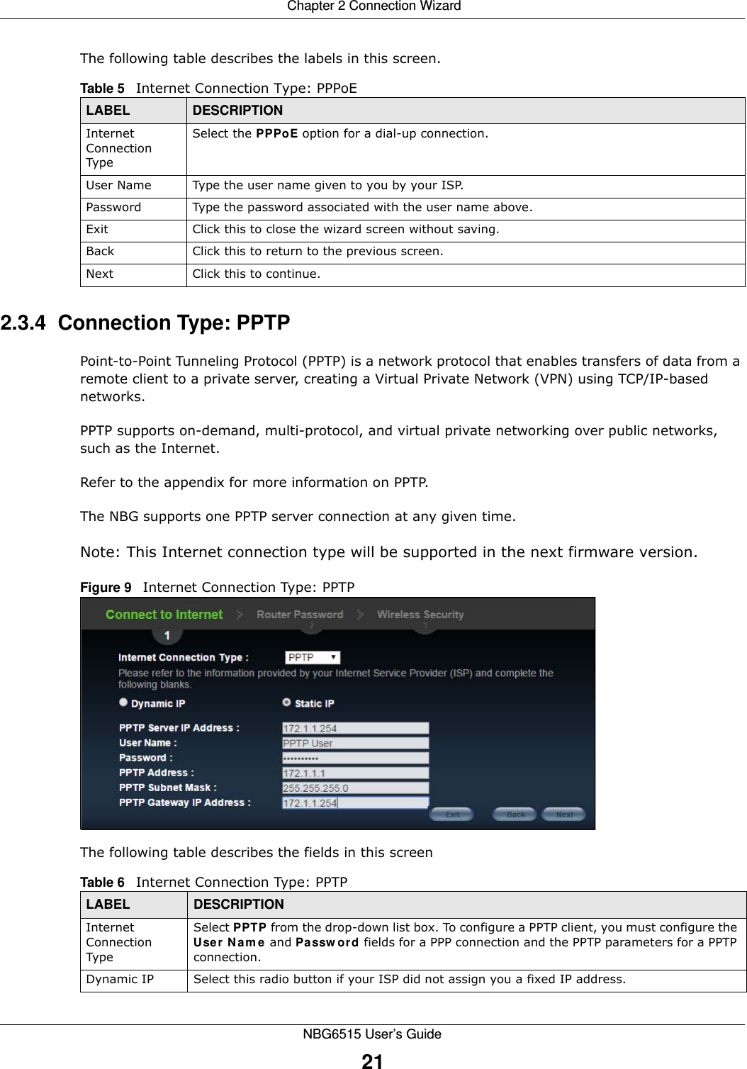
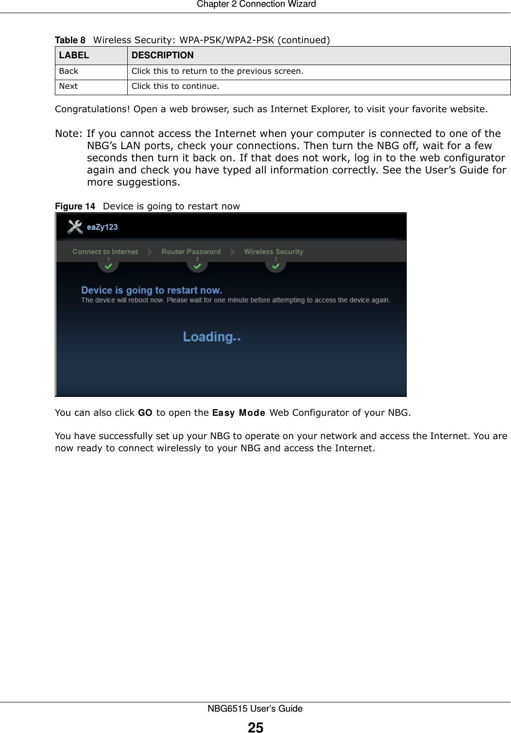
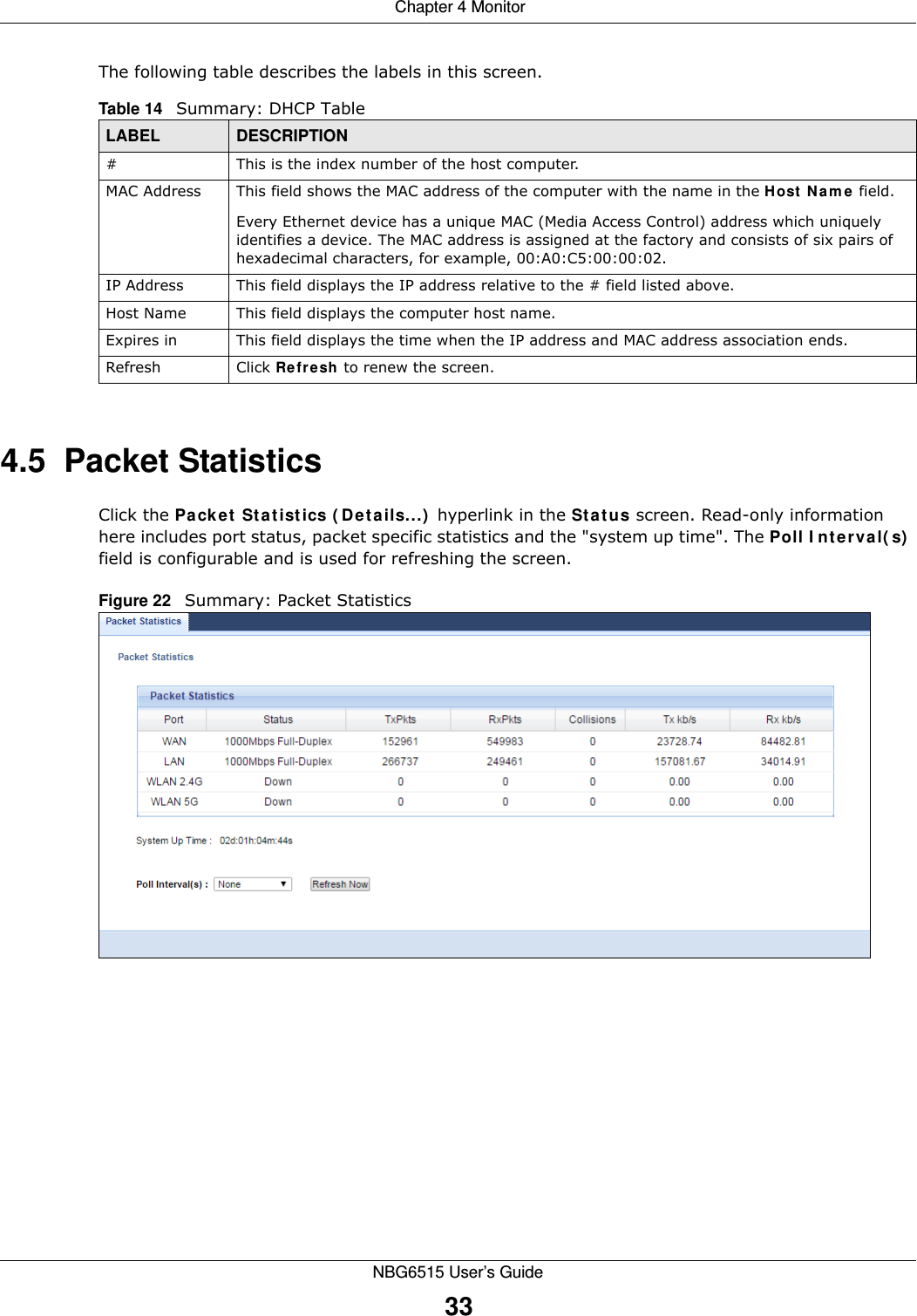
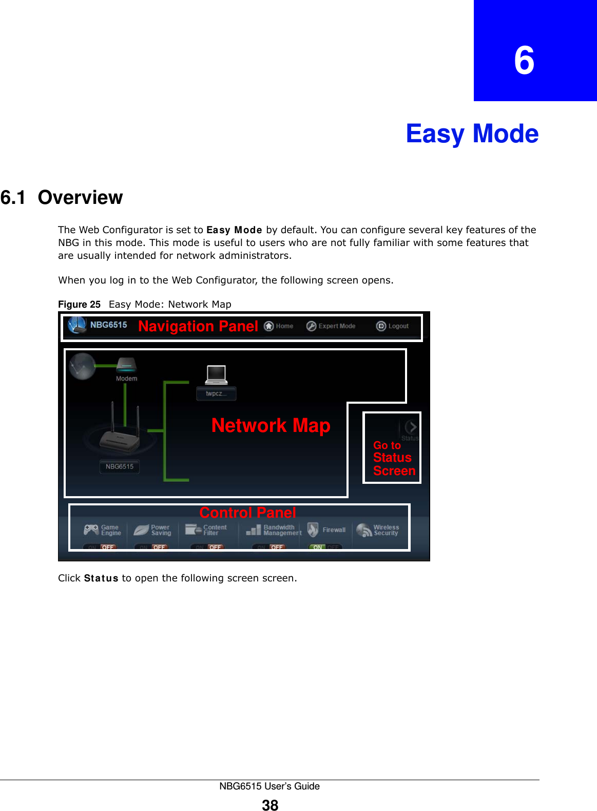
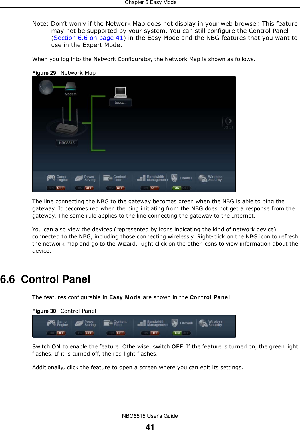
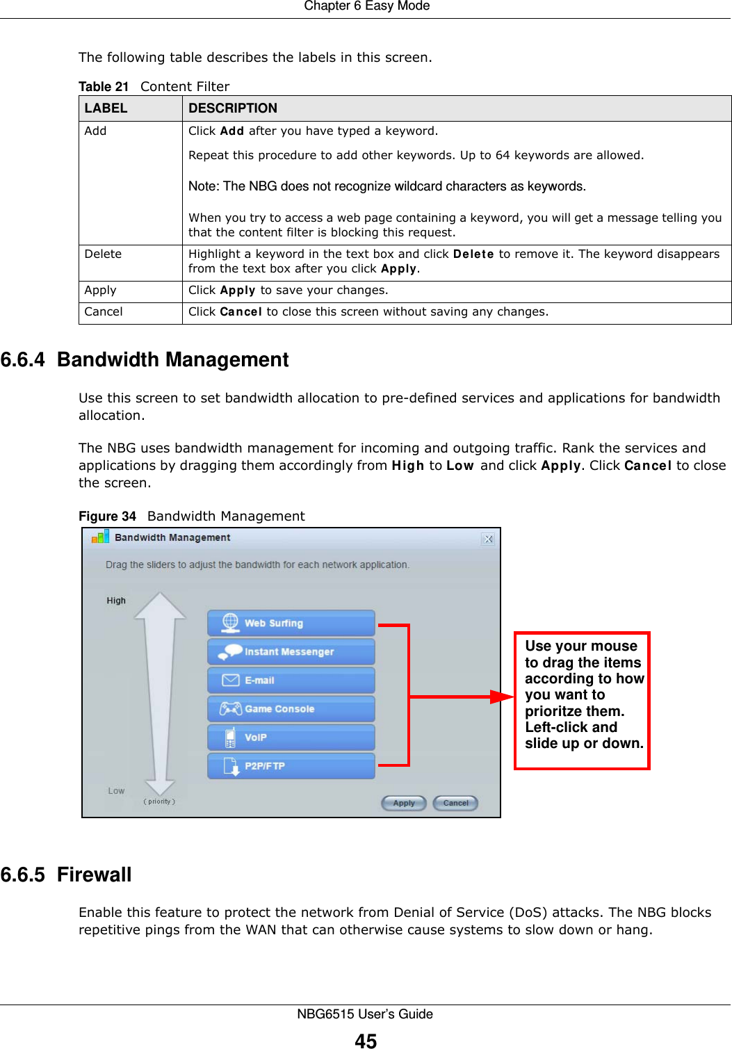
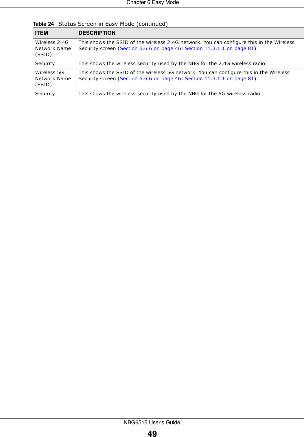
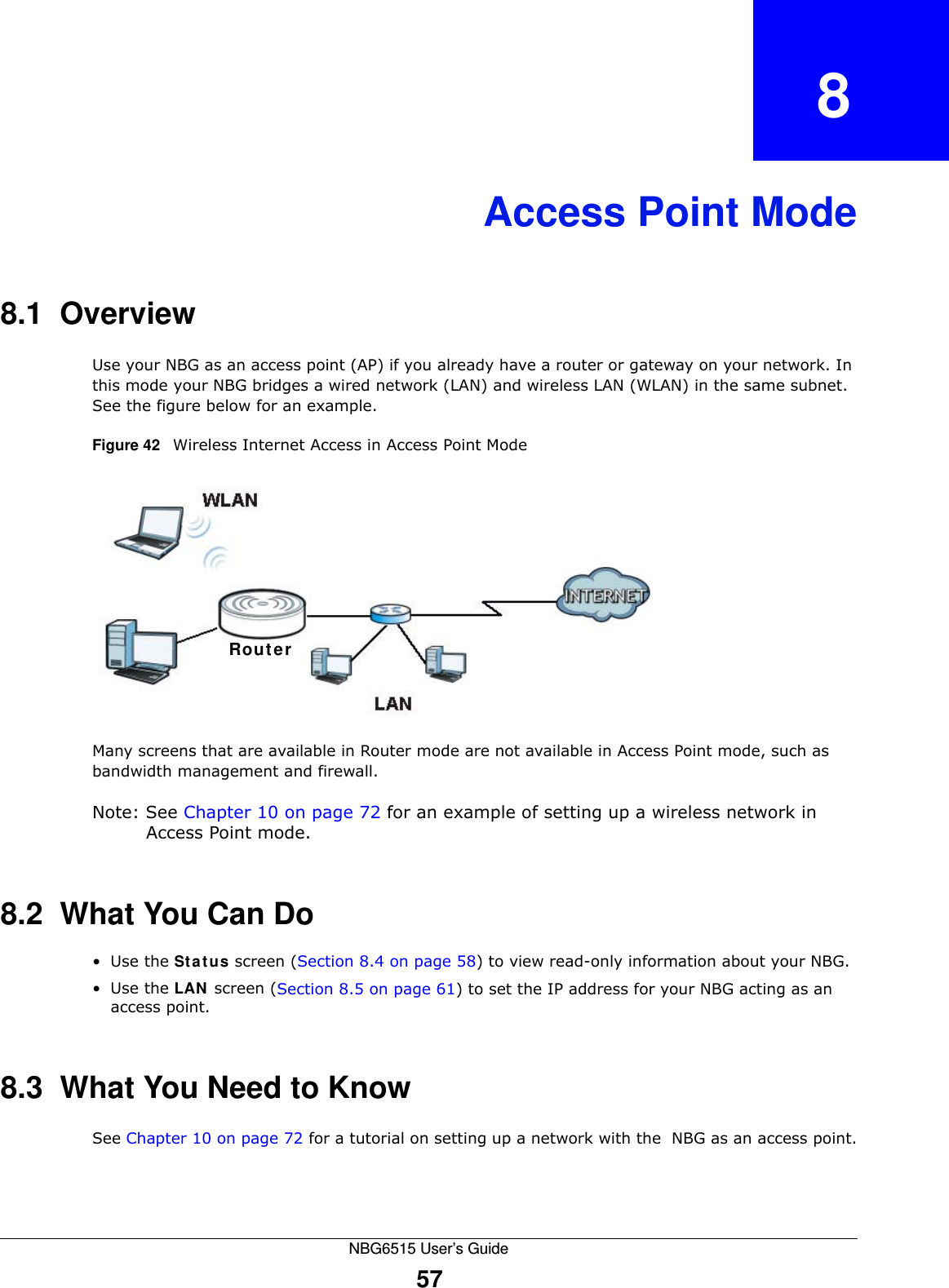
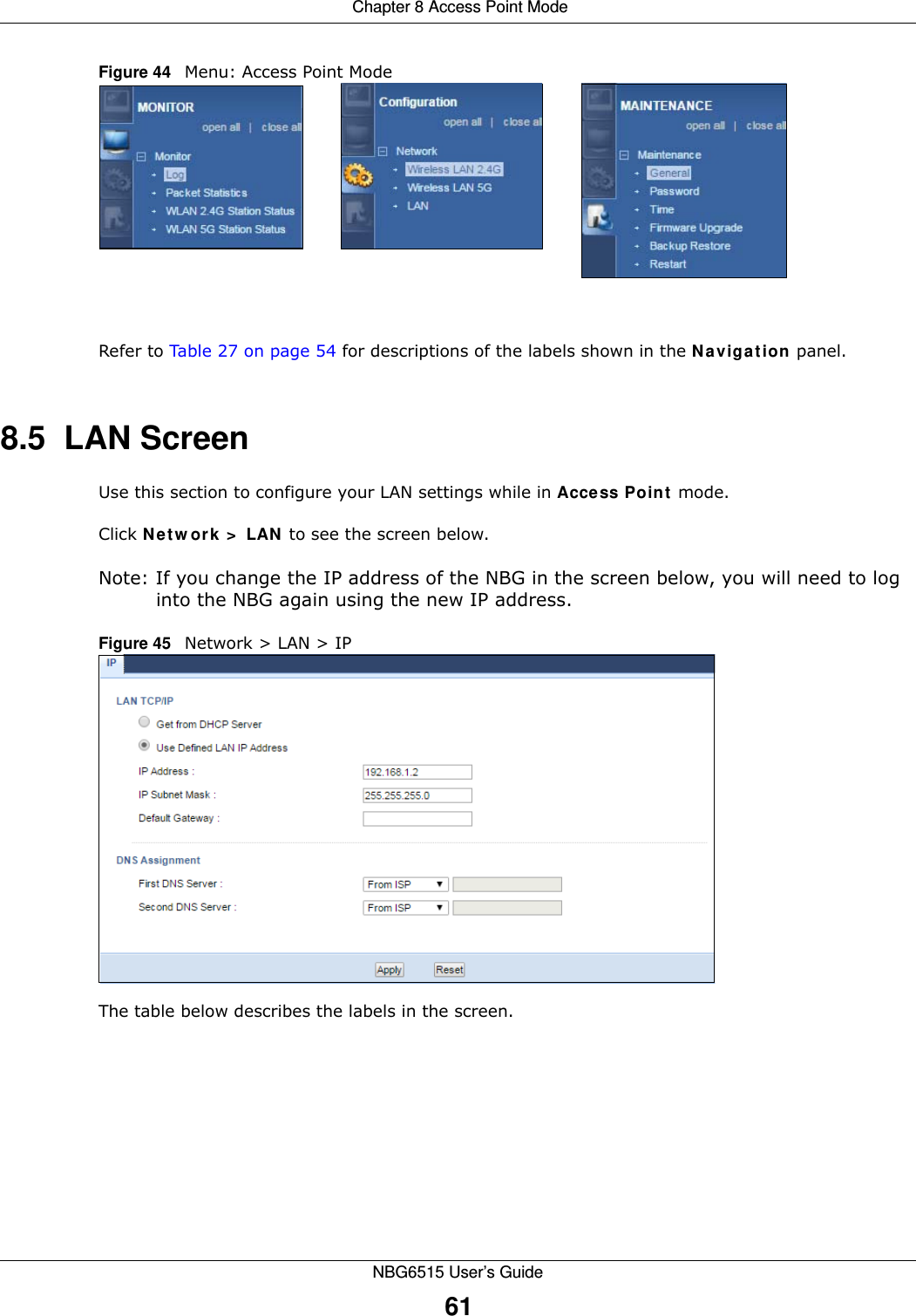
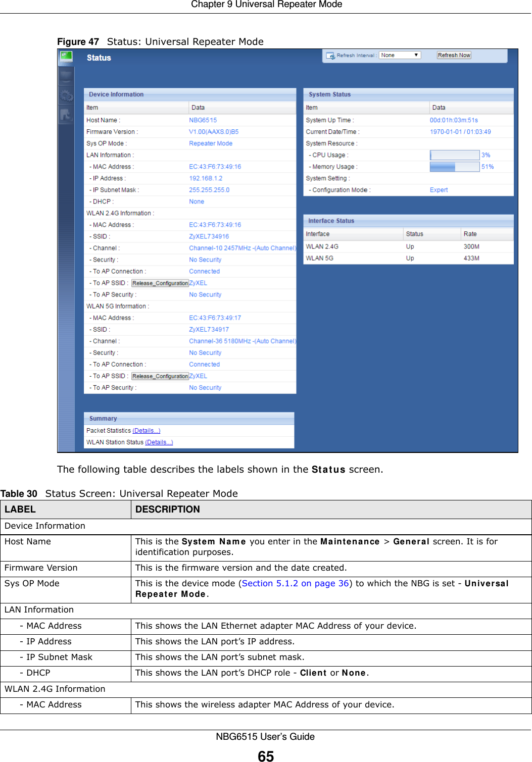
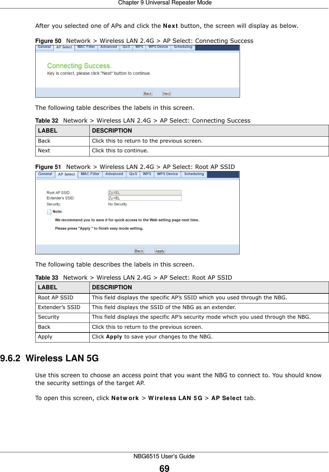
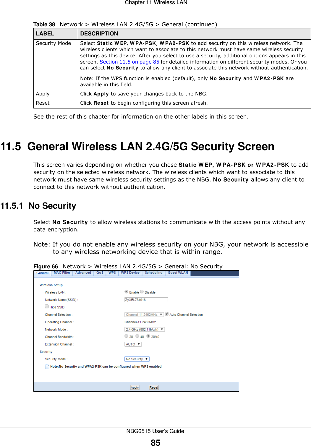

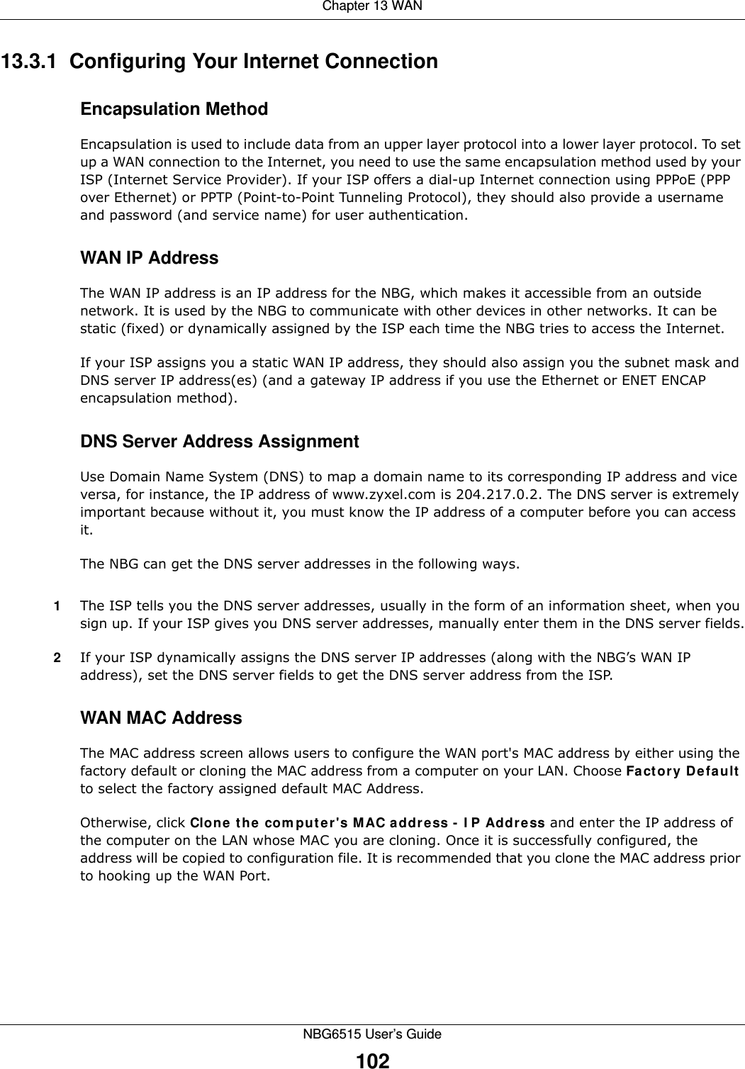
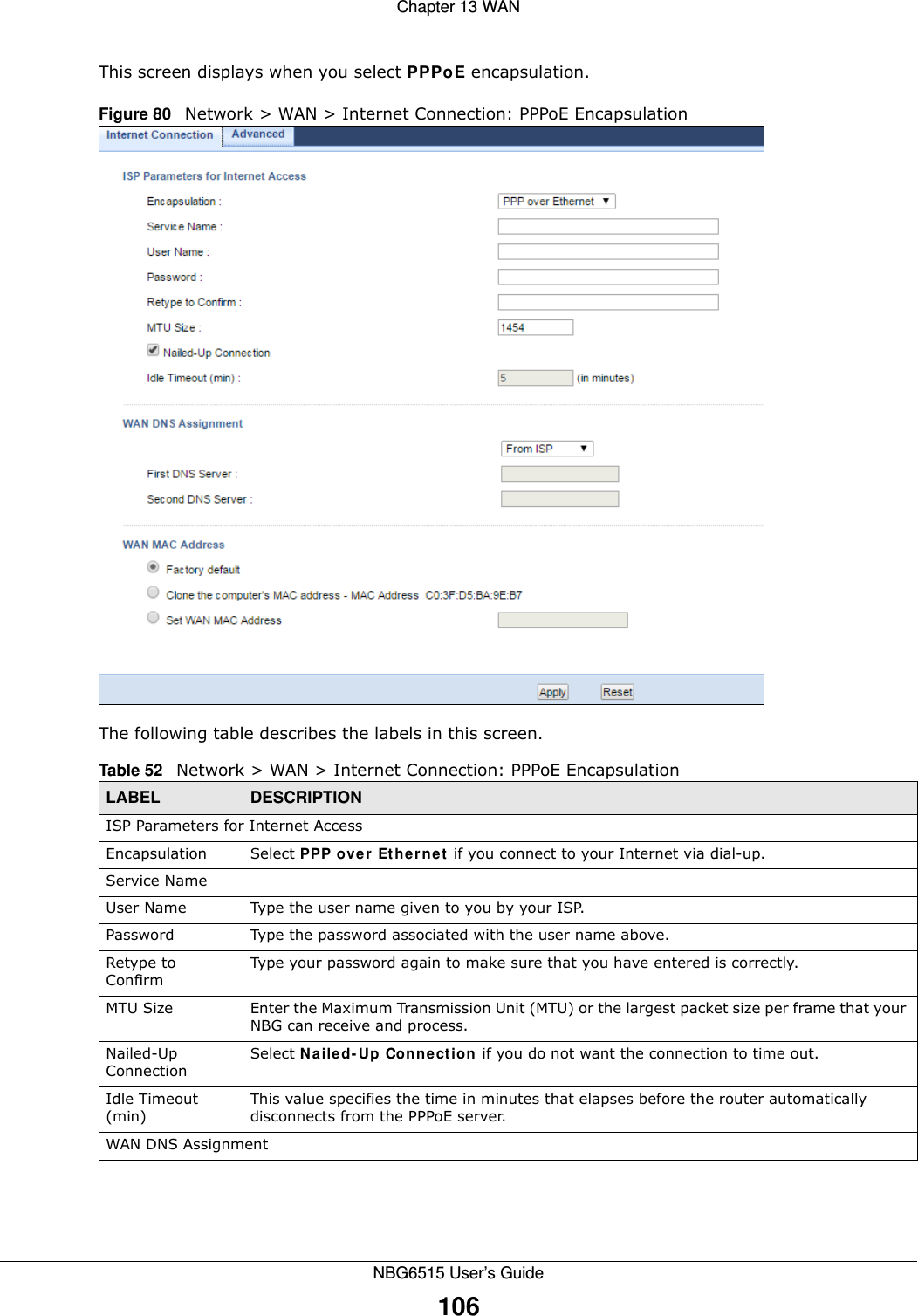
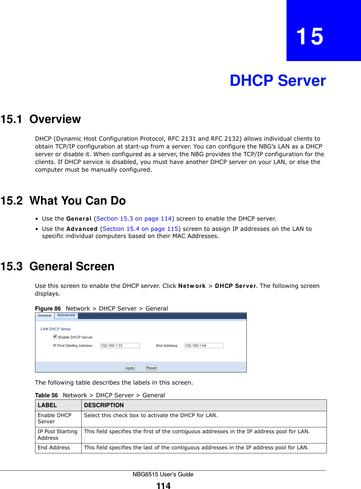
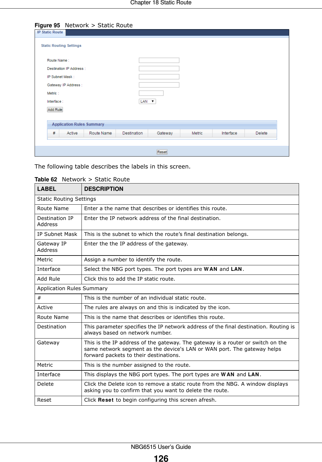
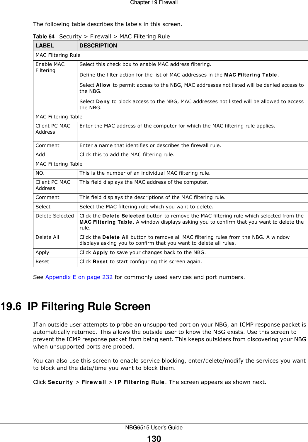
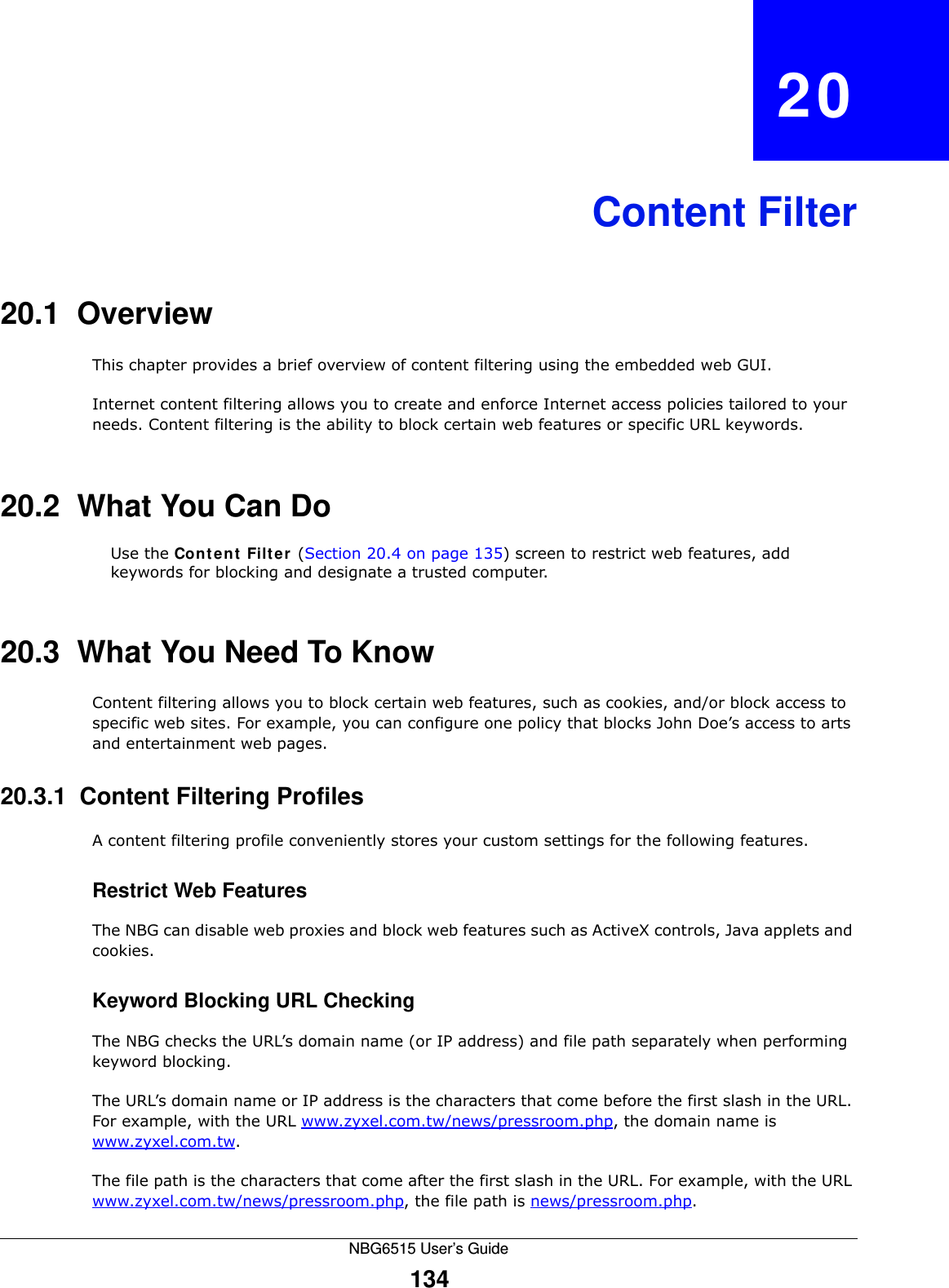
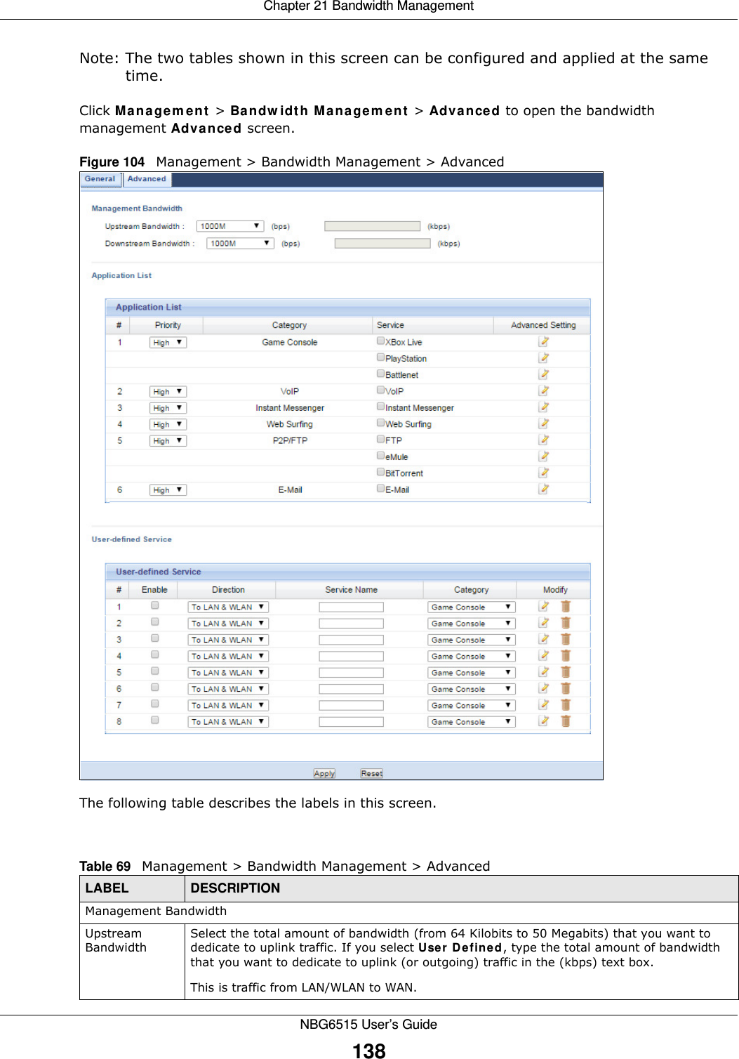
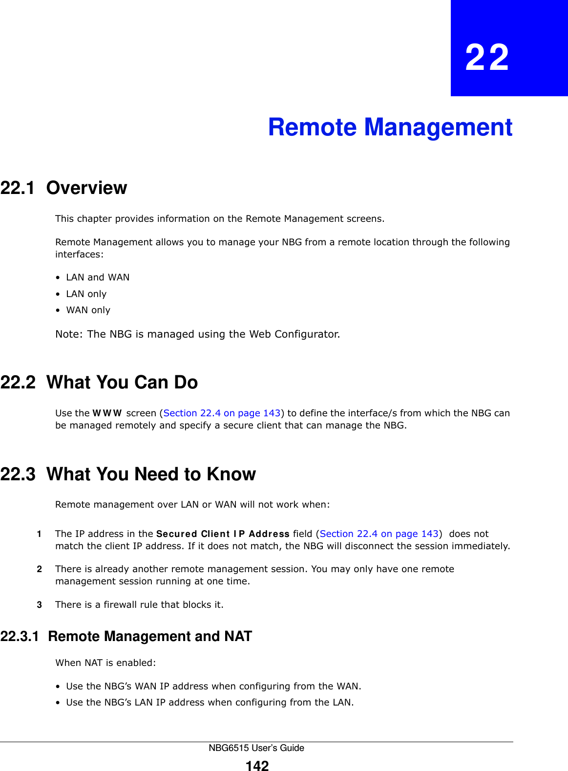
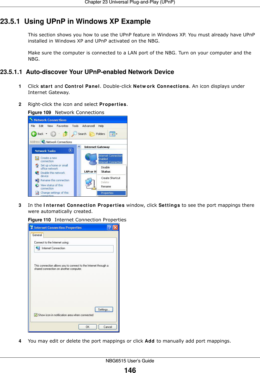
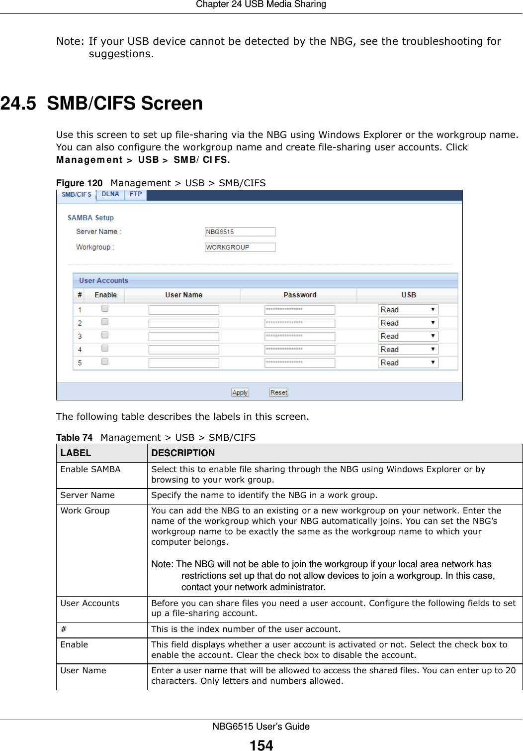
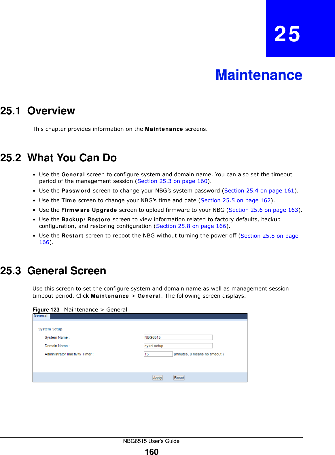
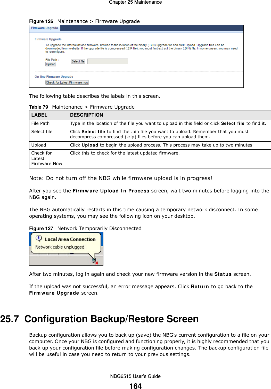
![Chapter 24 USB Media SharingNBG6515 User’s Guide157This example shows you how to use Microsoft’s Windows XP to browse your shared files. Refer to your operating system’s documentation for how to browse your file structure. 24.8.1 Use Windows Explorer to Share Files You should have enabled file sharing and created a user account (Bob/1234 for example) with read and write access to USB in the USB > SMB/CIFS screen.Open Windows Explorer to access the connected USB device using either Windows Explorer browser or by browsing to your workgroup.1In Windows Explorer’s Address bar type a double backslash “\\” followed by the IP address of the NBG (the default IP address of the NBG in router mode is 192.168.1.1) and press [ENTER]. A screen asking for password authentication appears. Type the user name and password (Bob and 1234 in this example) and click OK.Note: Once you log into the shared folder via your NBG, you do not have to relogin unless you restart your computer.](https://usermanual.wiki/ZyXEL-Communications/NBG6515.Users-Manual/User-Guide-2693921-Page-157.png)
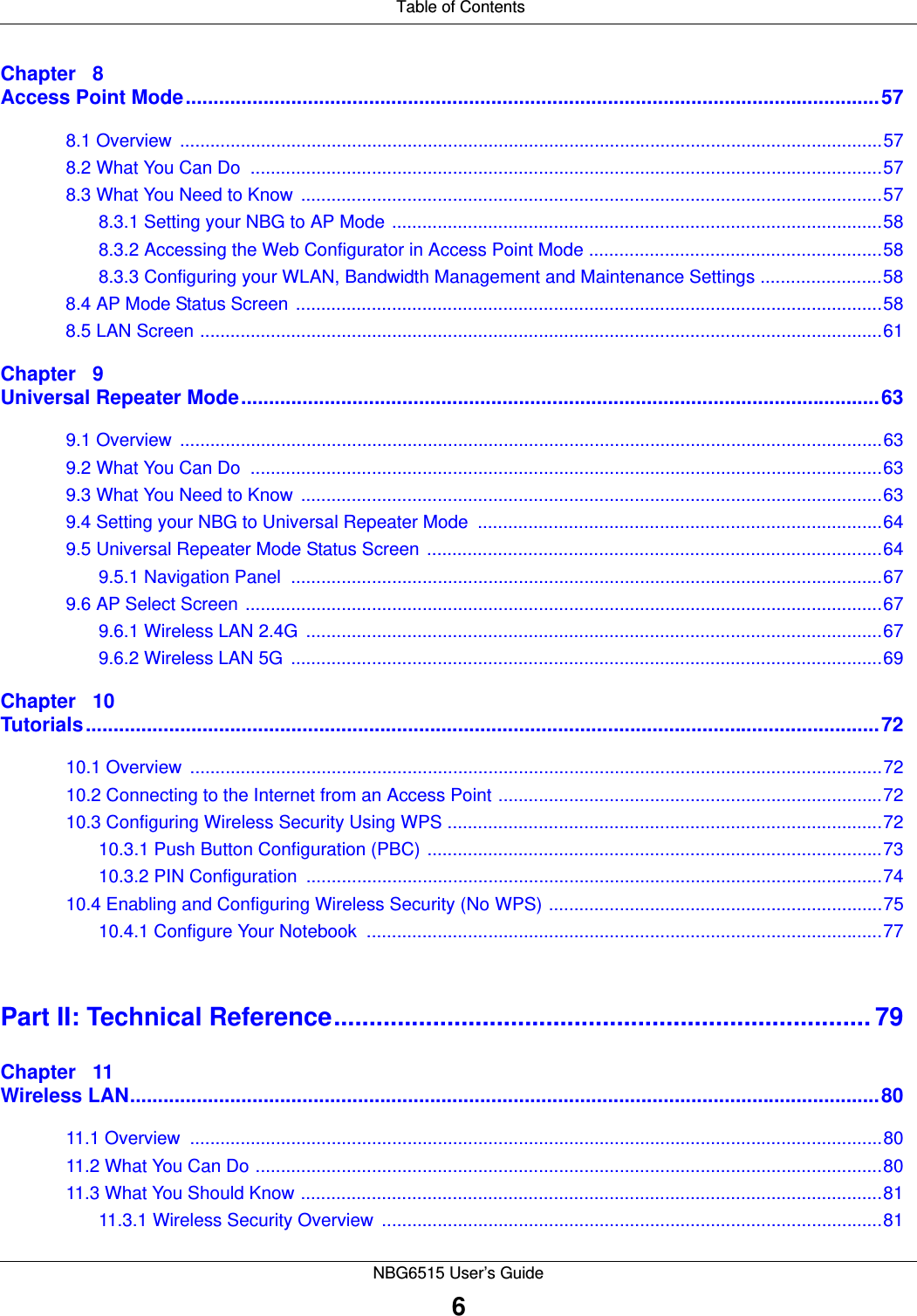
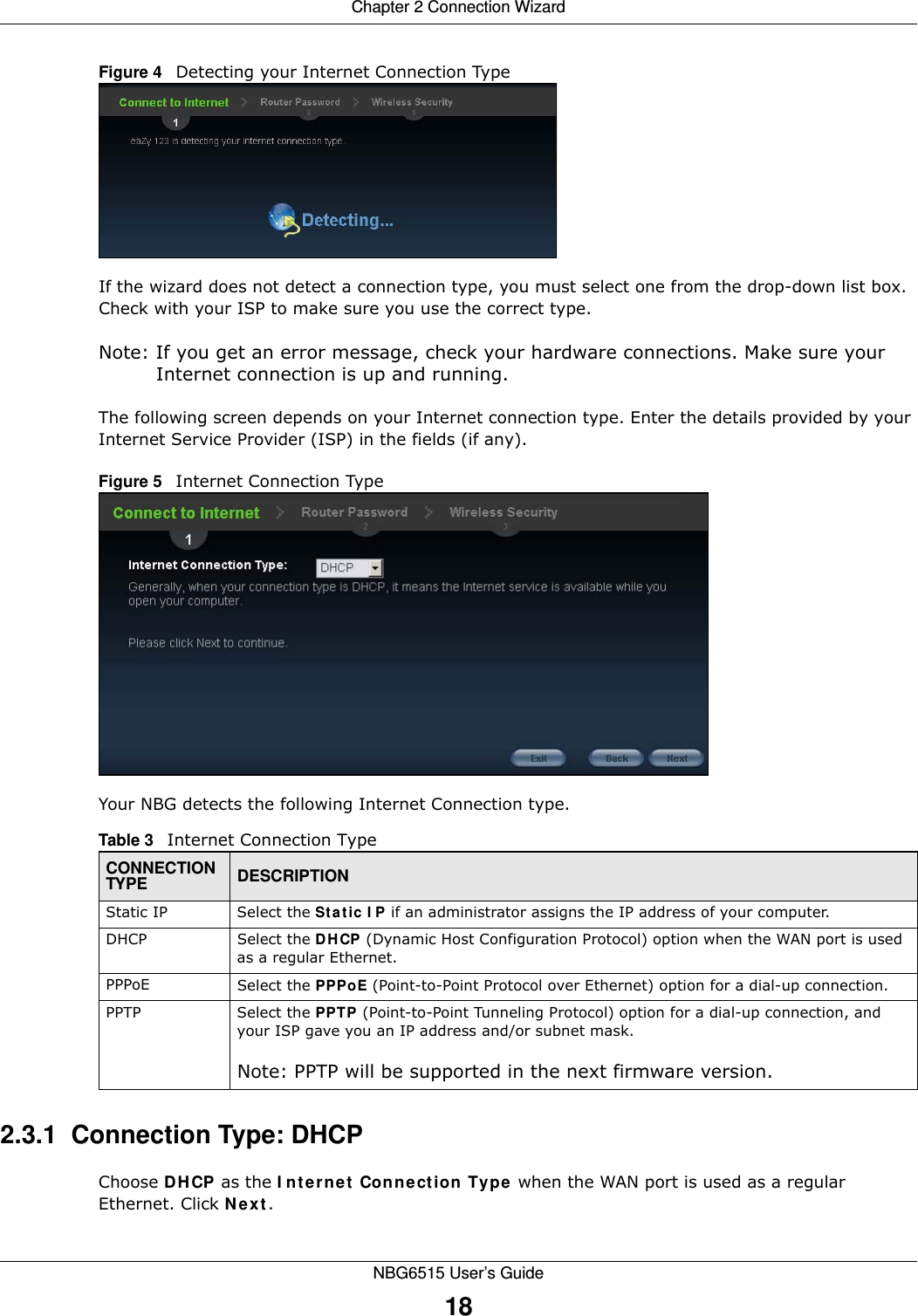
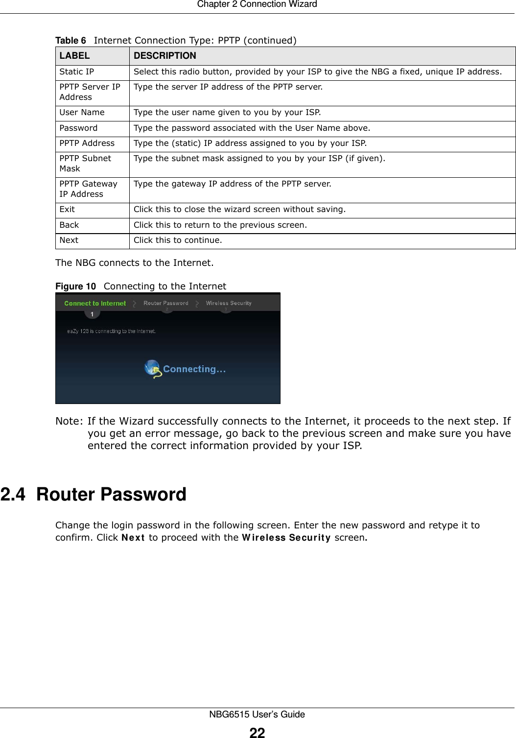
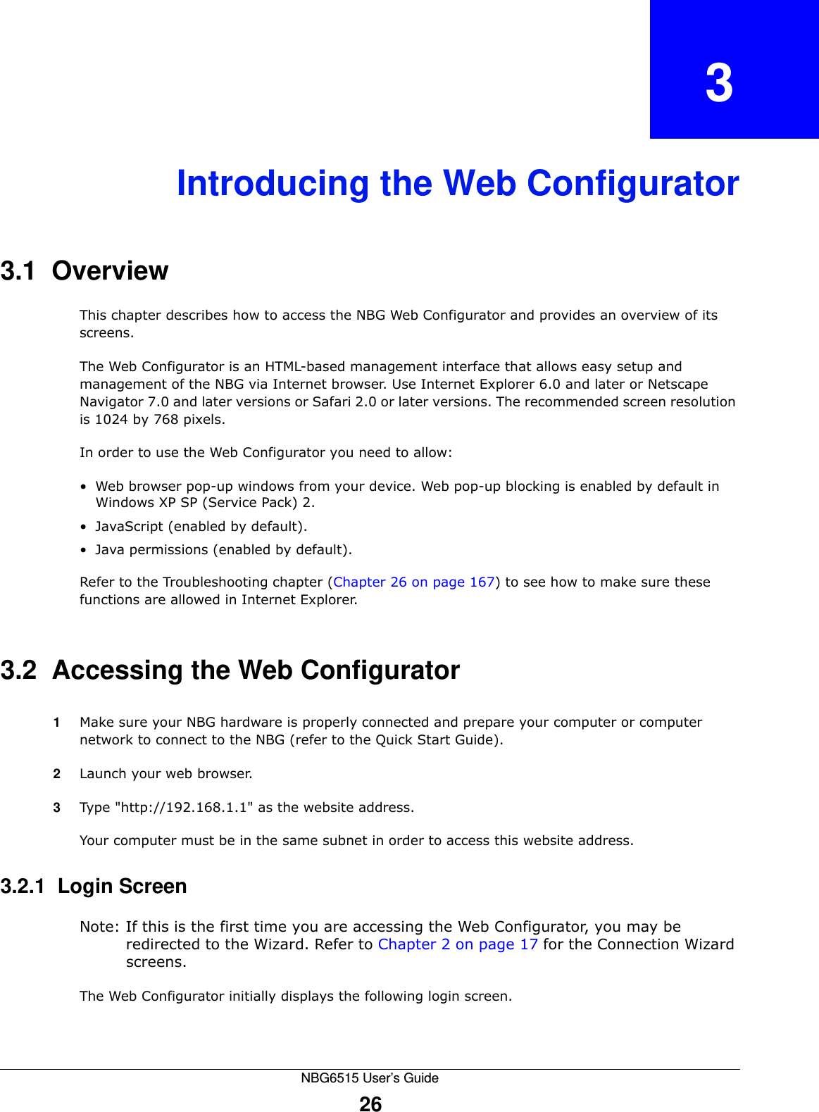
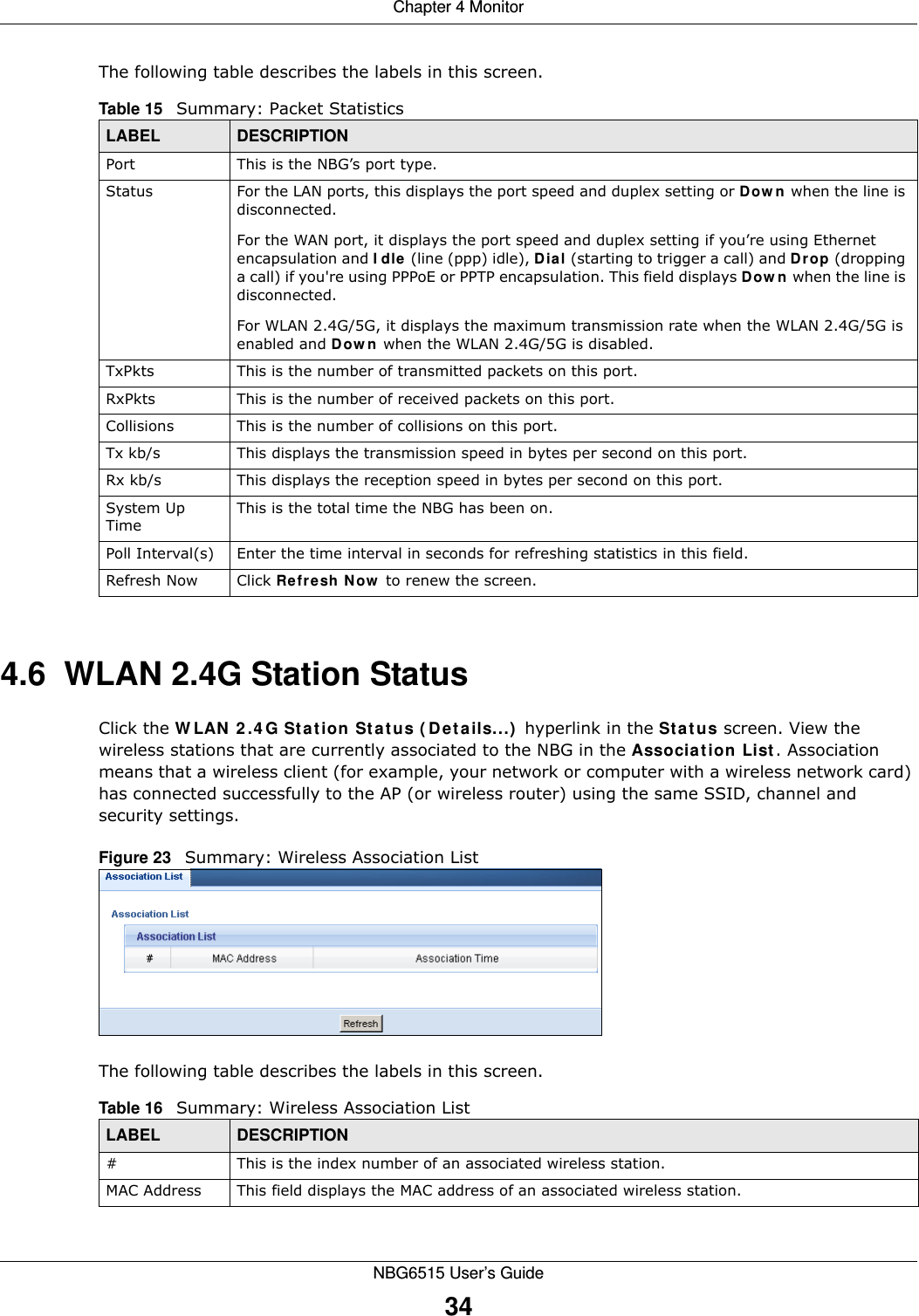
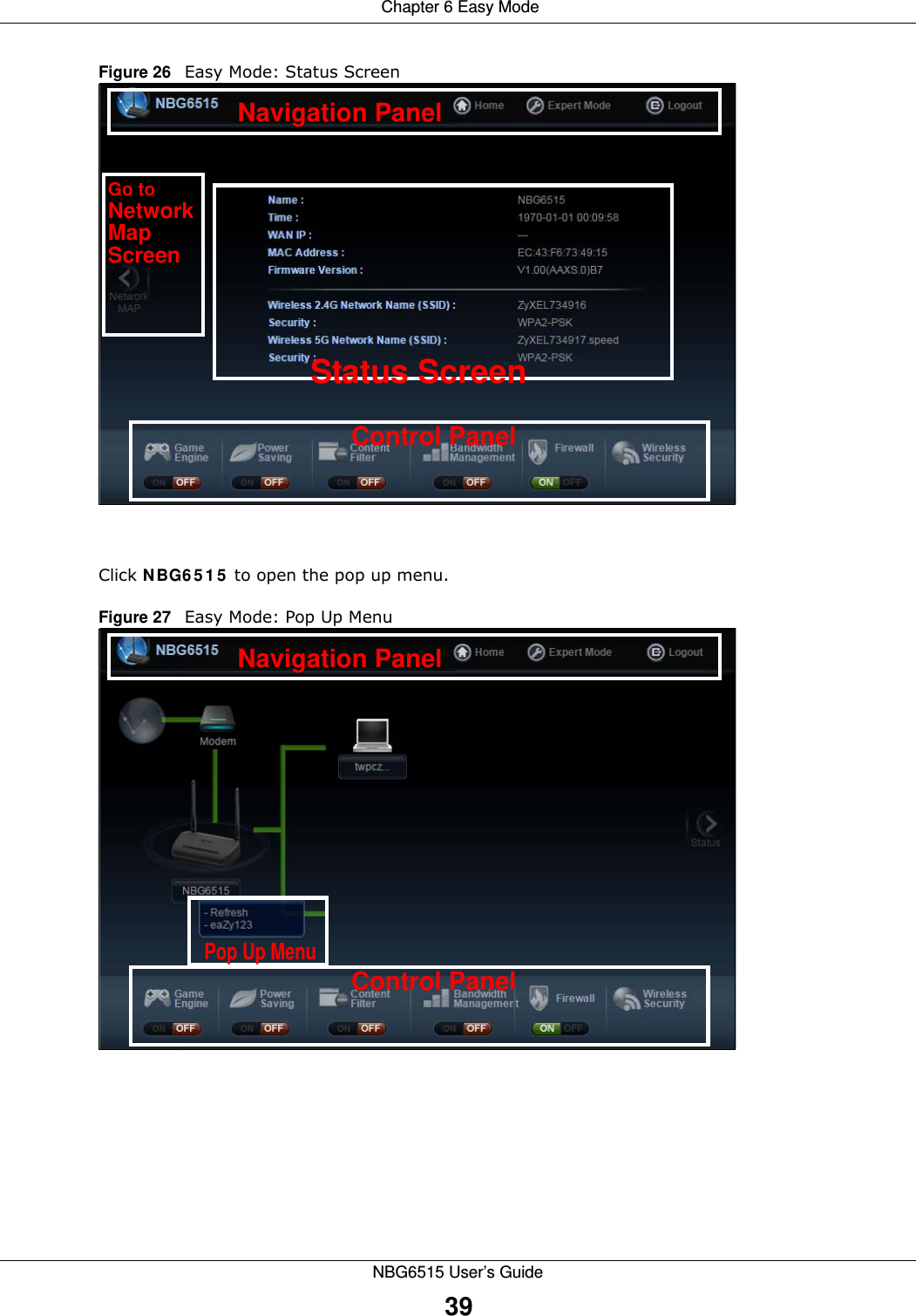
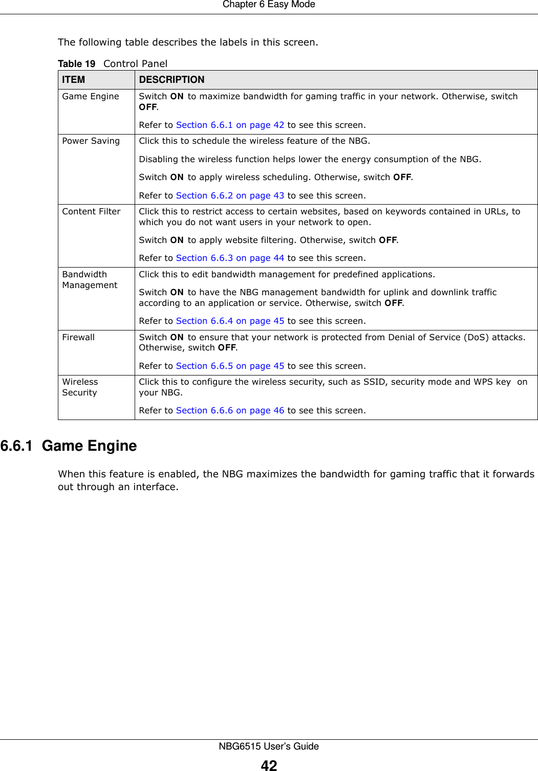
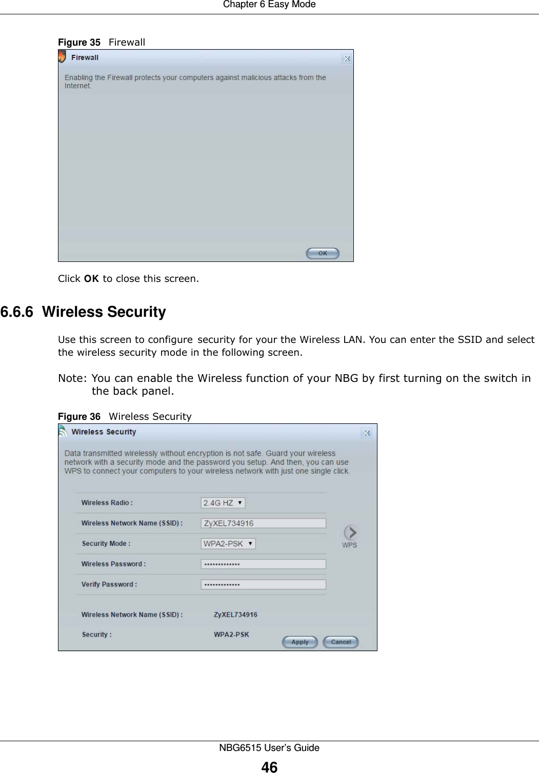
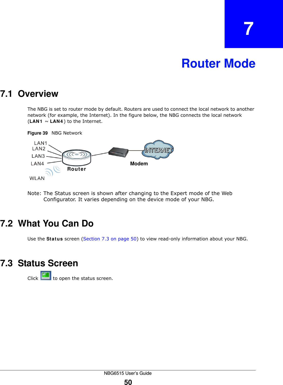
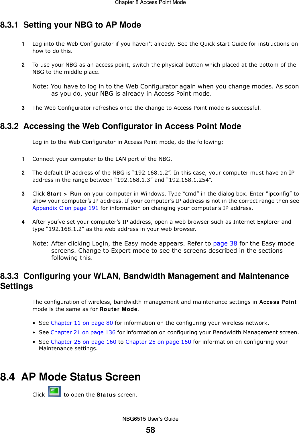
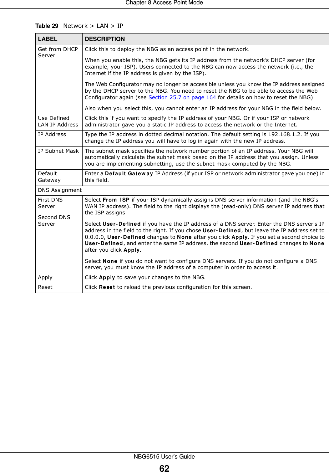
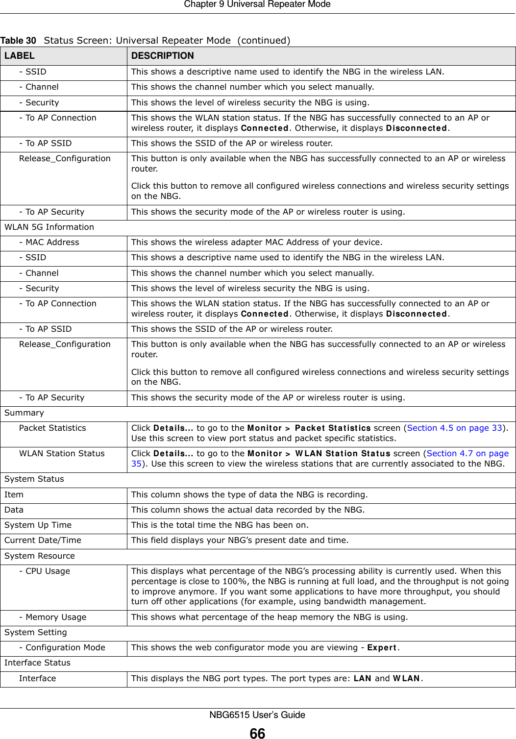
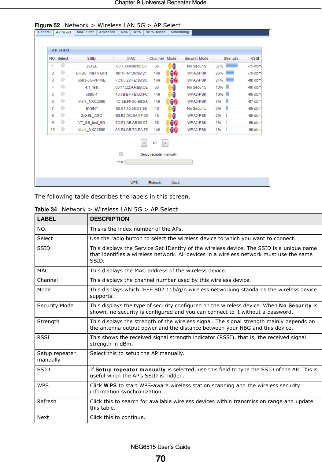
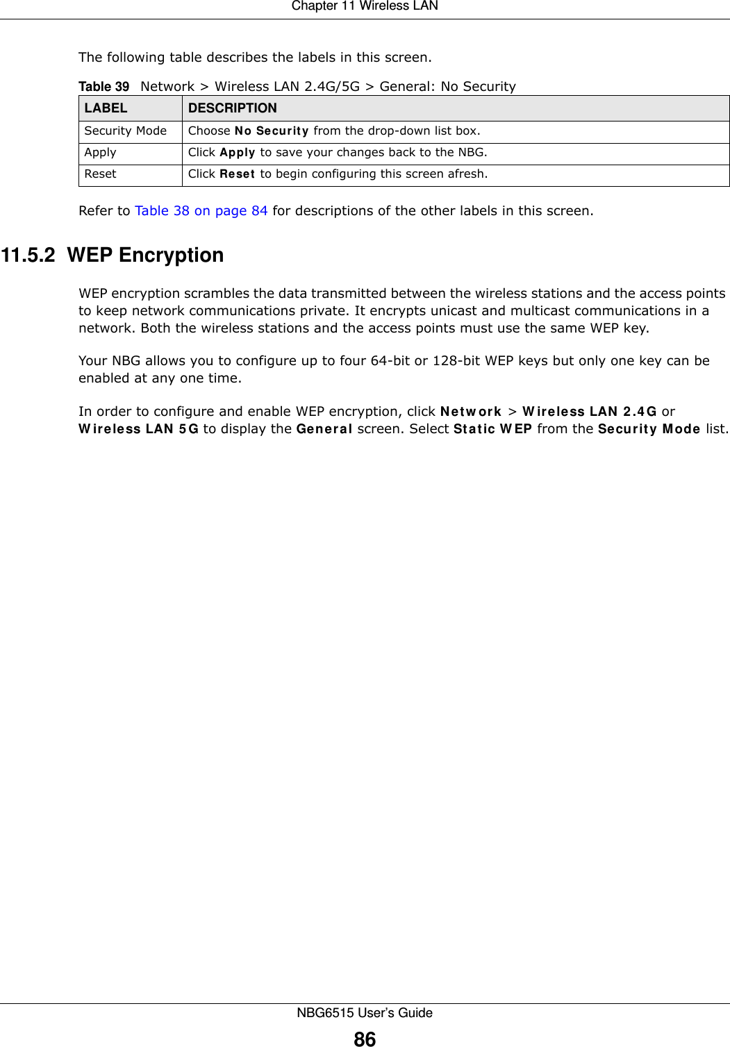
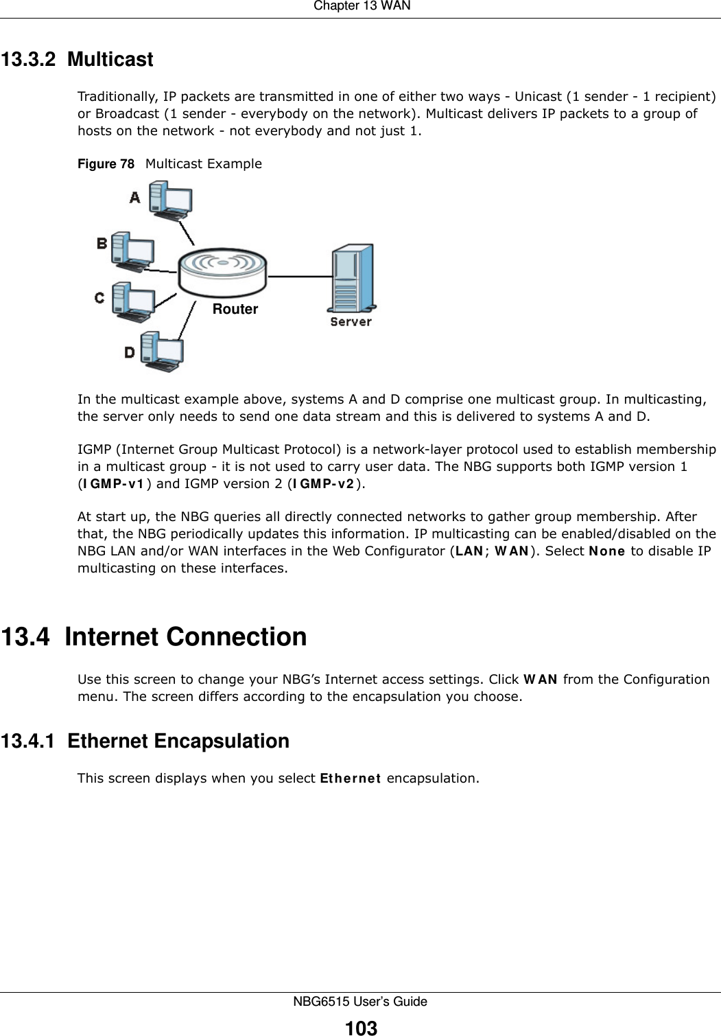
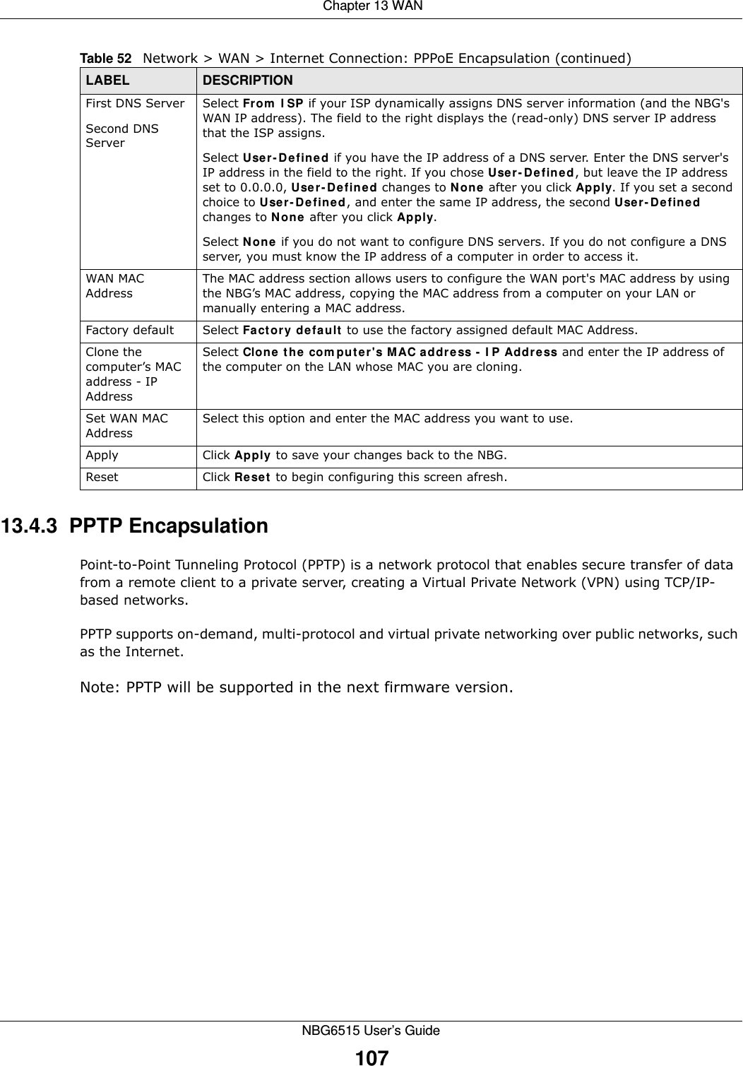
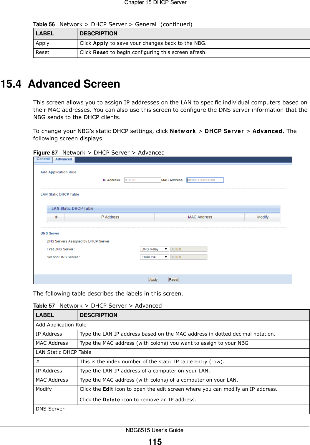
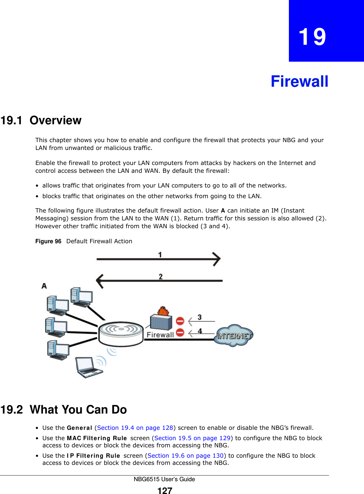
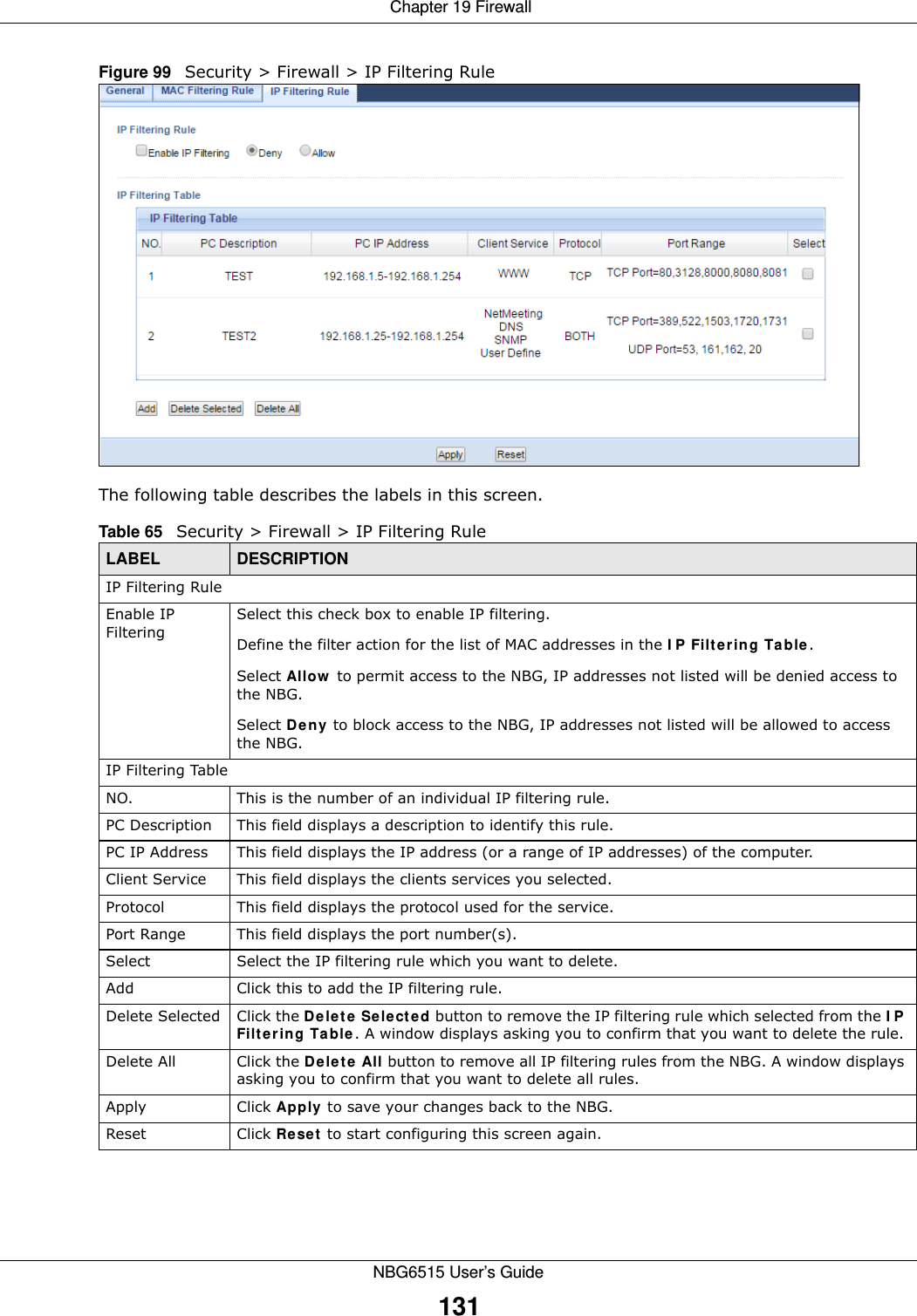
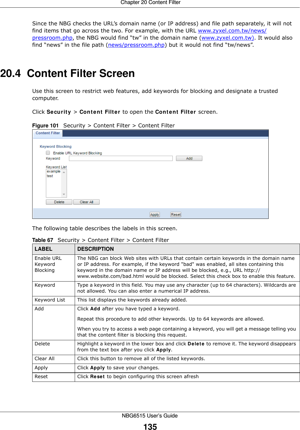
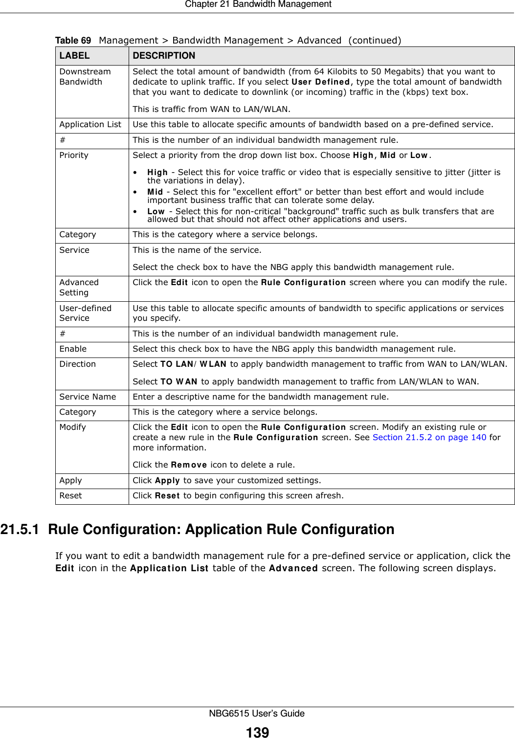
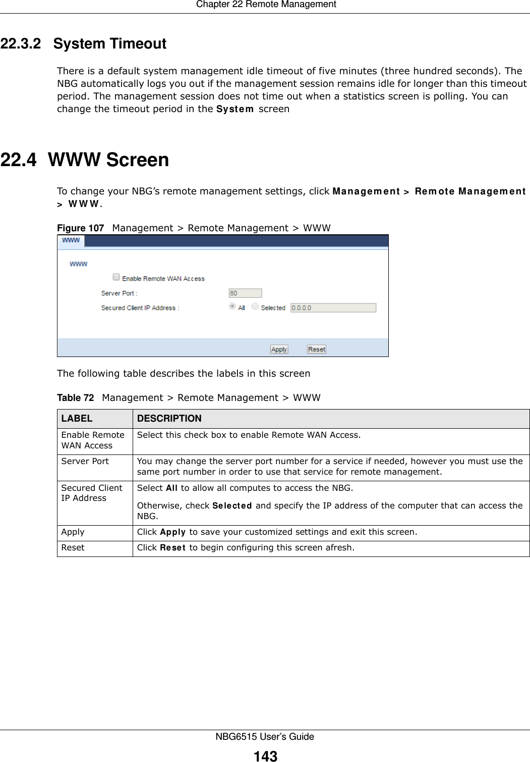
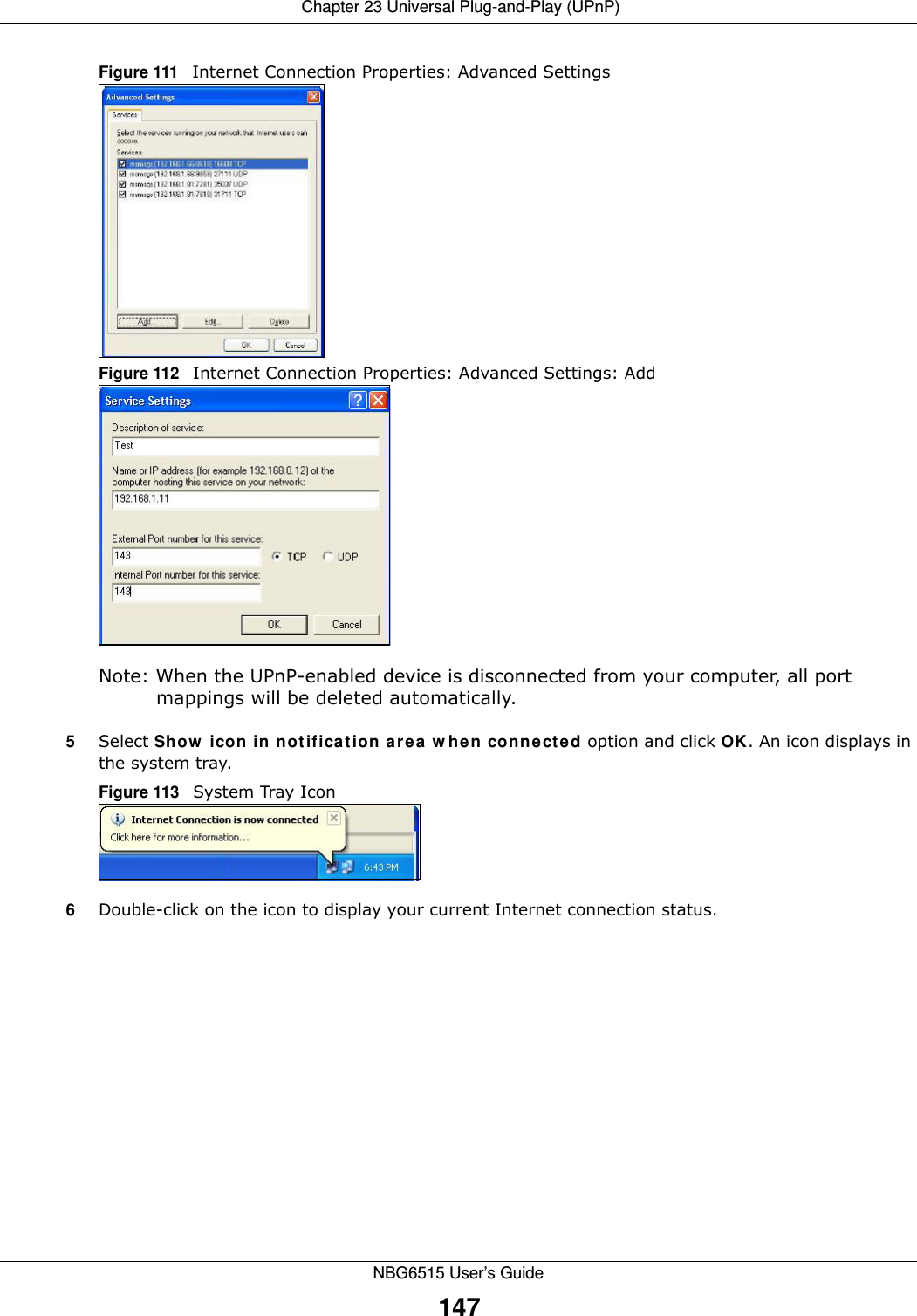
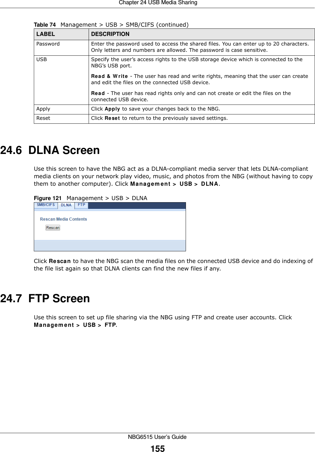
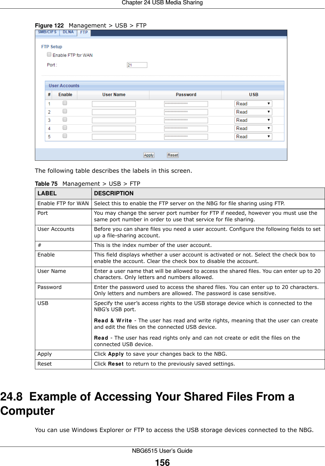
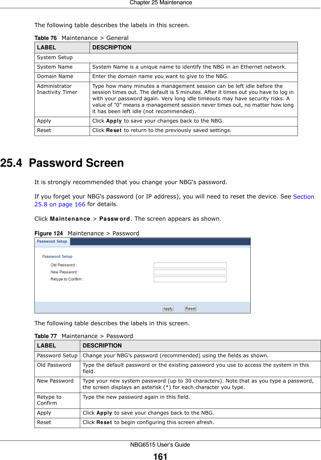
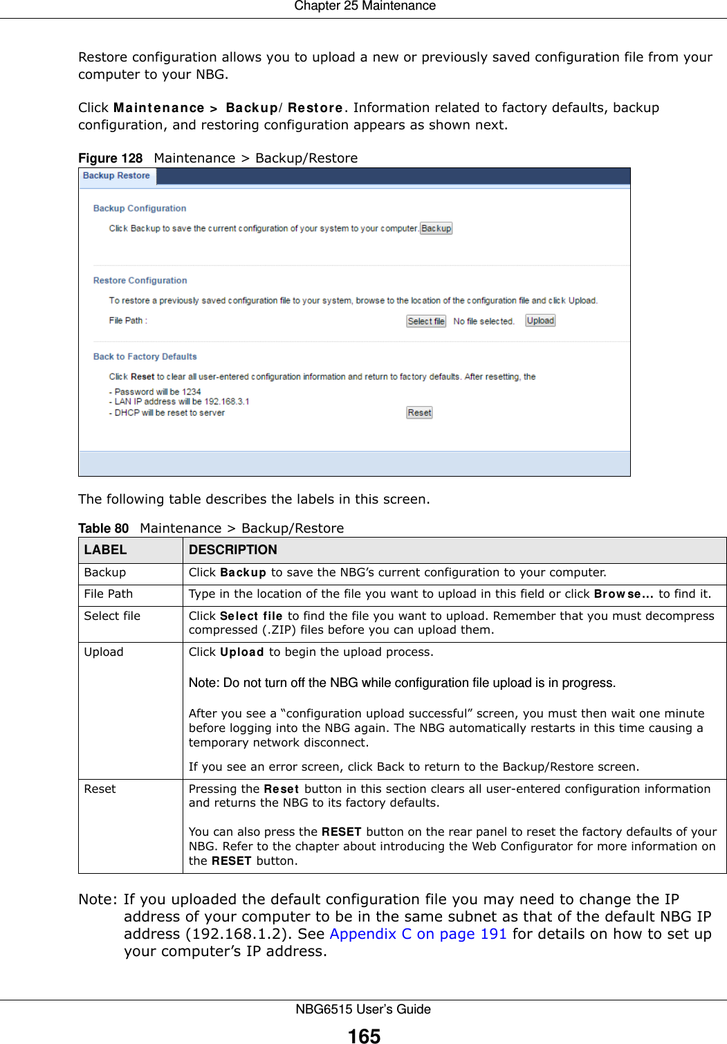
![Chapter 24 USB Media SharingNBG6515 User’s Guide1582You can also use the workgroup name to access files by browsing to the workgroup folder using the folder tree on the left side of the screen. It is located under My Network Places. In this example the workgroup name is the default “Workgroup”. 24.8.2 Use FTP to Share FilesYou can use FTP to access the USB storage devices connected to the NBG. In this example, we use the web browser to share files via FTP from the LAN. The way or screen you log into the FTP server (on the NBG) varies depending on your FTP client. See your FTP client documentation for more information. You should have enabled file sharing and created a user account (Bob/1234 for example) with read and write access to USB in the USB > FTP screen.1In your web browser’s address or URL bar type “ftp://” followed by the IP address of the NBG (the default LAN IP address of the NBG in router mode is 192.168.1.1) and click Go or press [ENTER].](https://usermanual.wiki/ZyXEL-Communications/NBG6515.Users-Manual/User-Guide-2693921-Page-158.png)
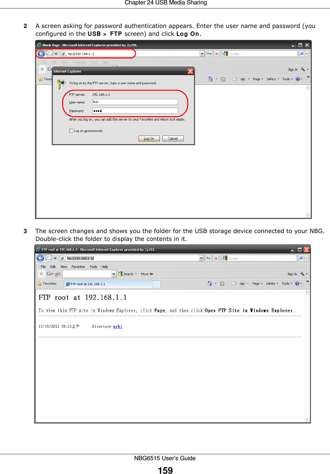
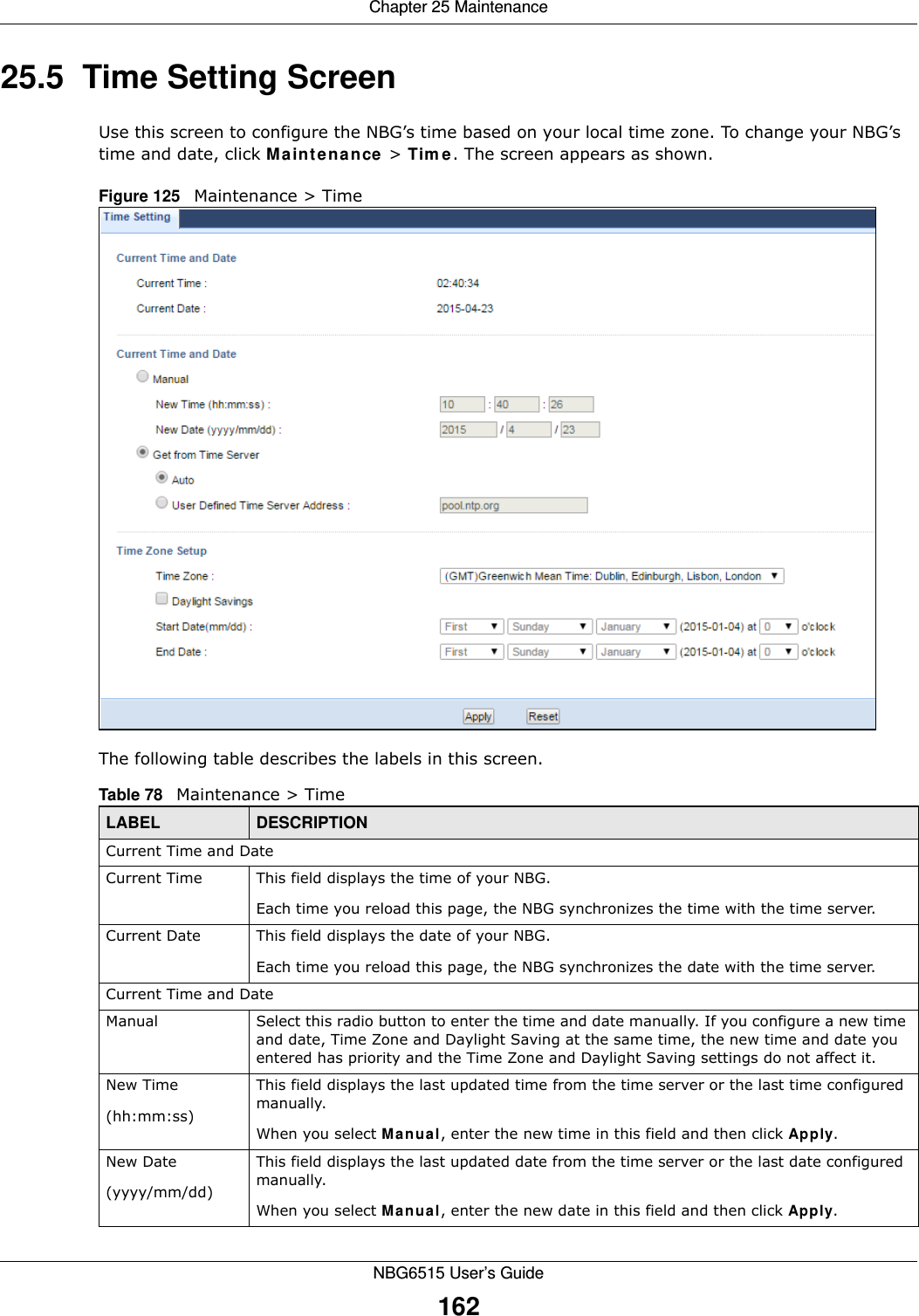
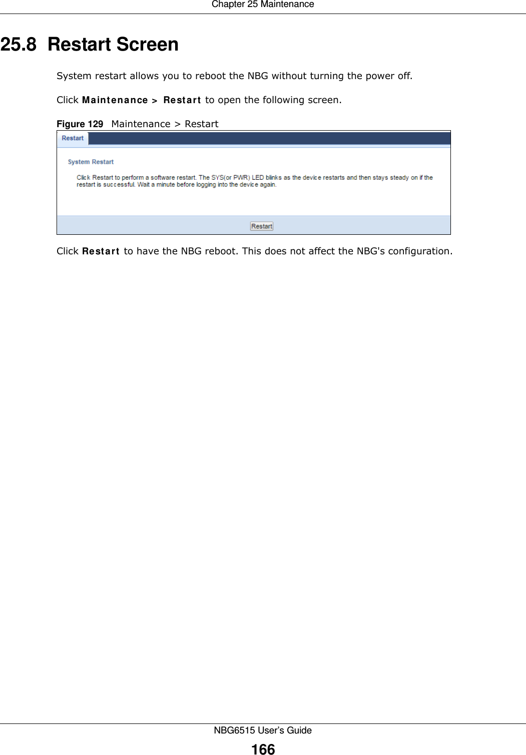
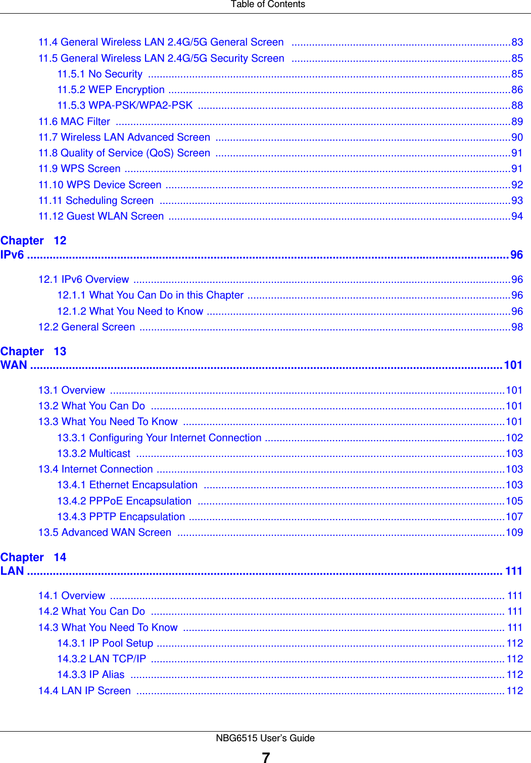
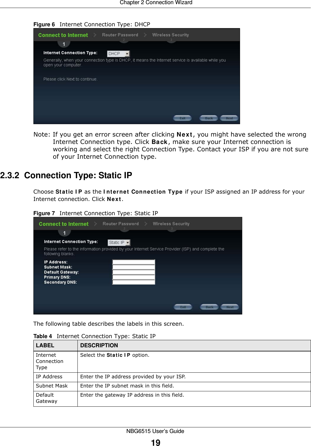
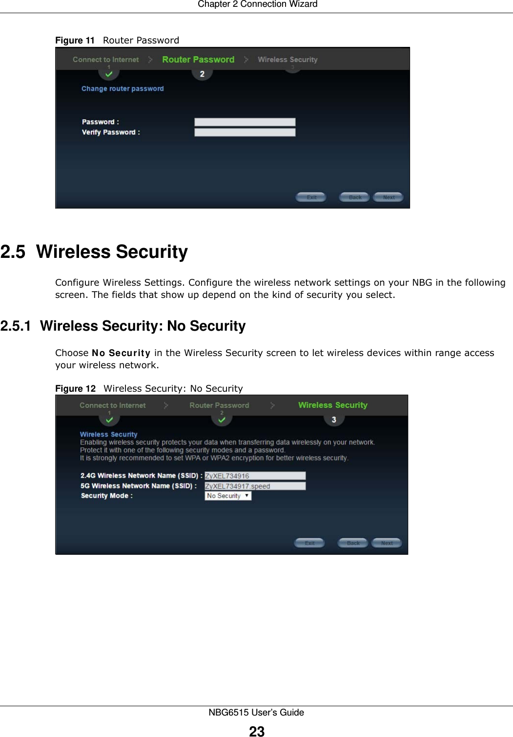
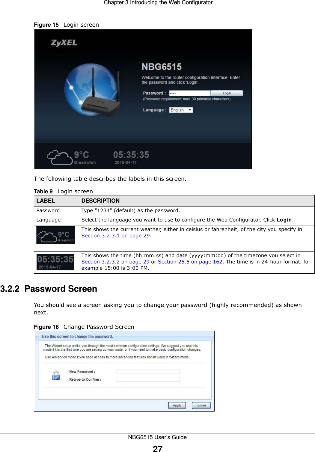
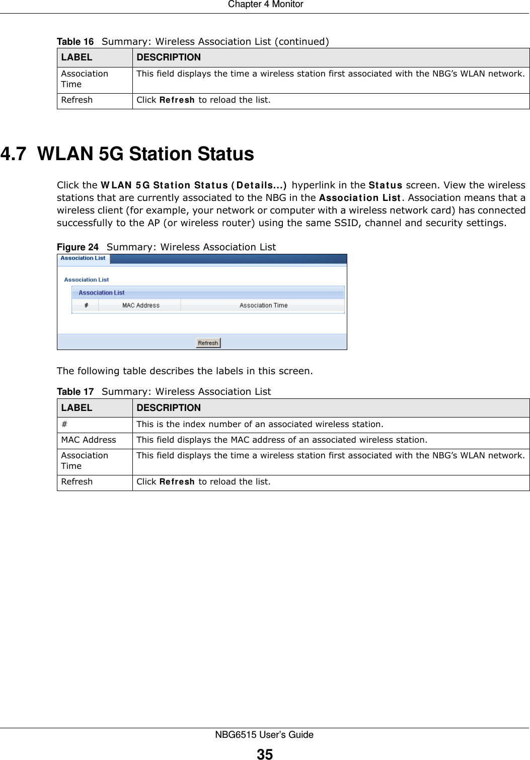
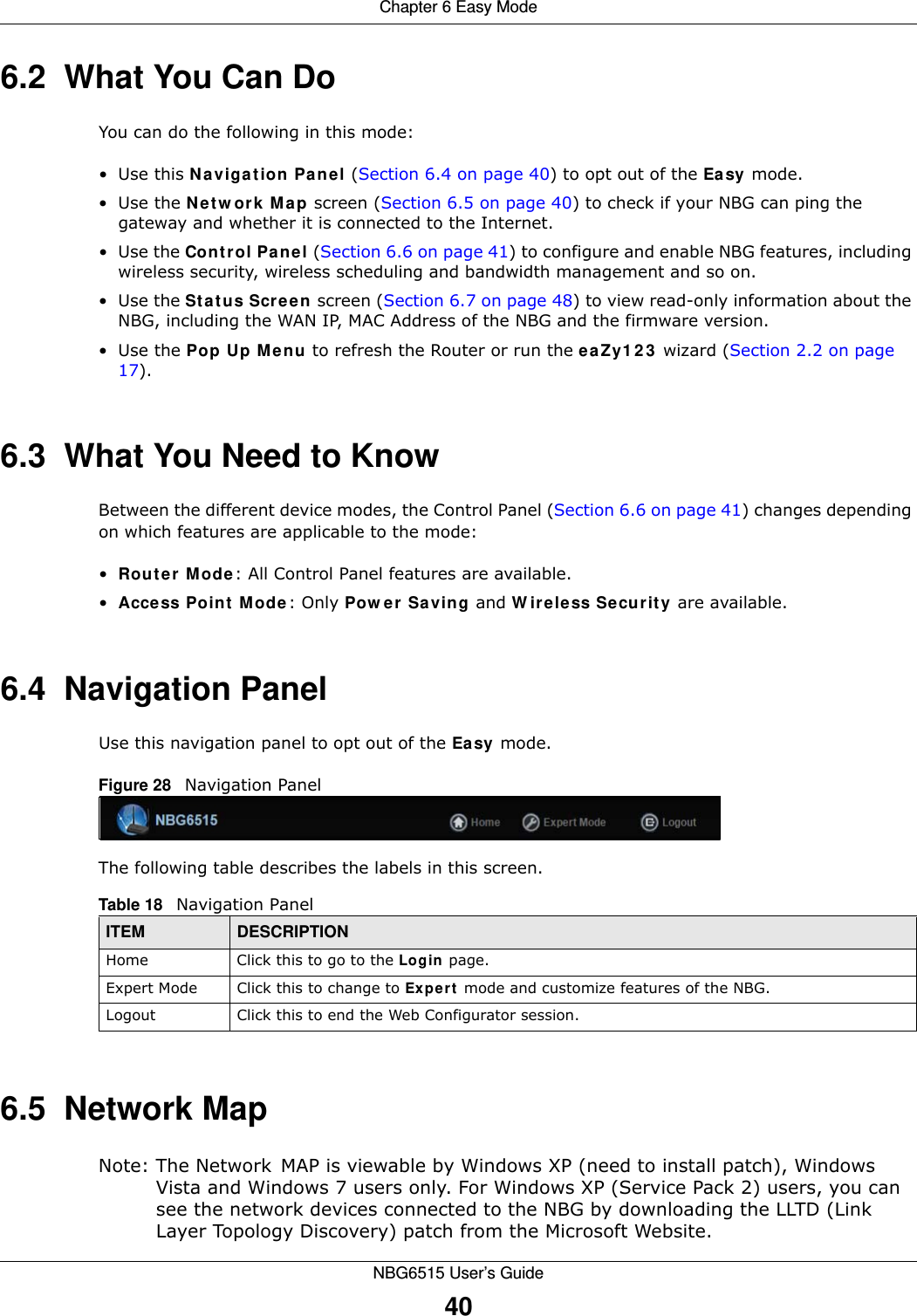
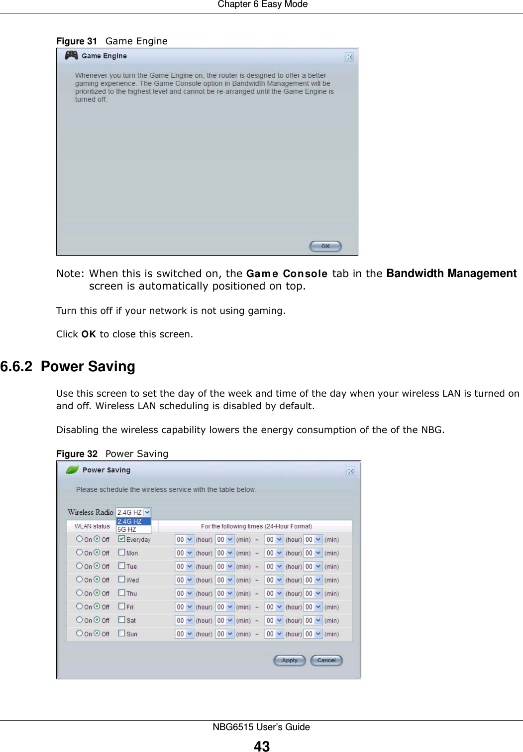
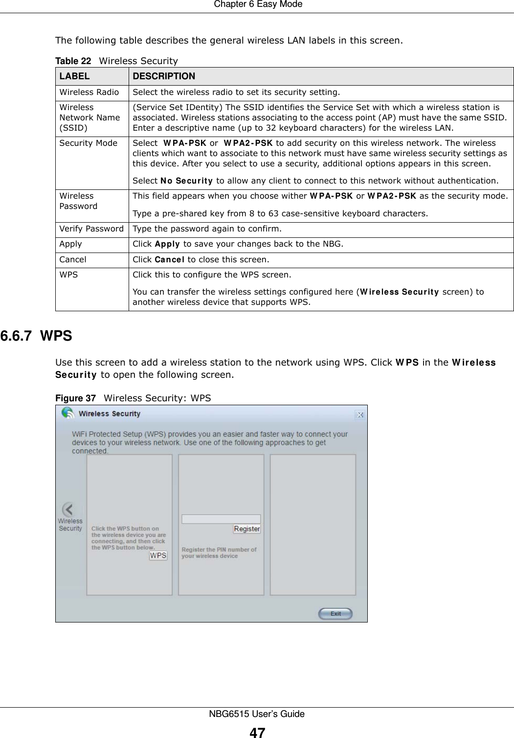
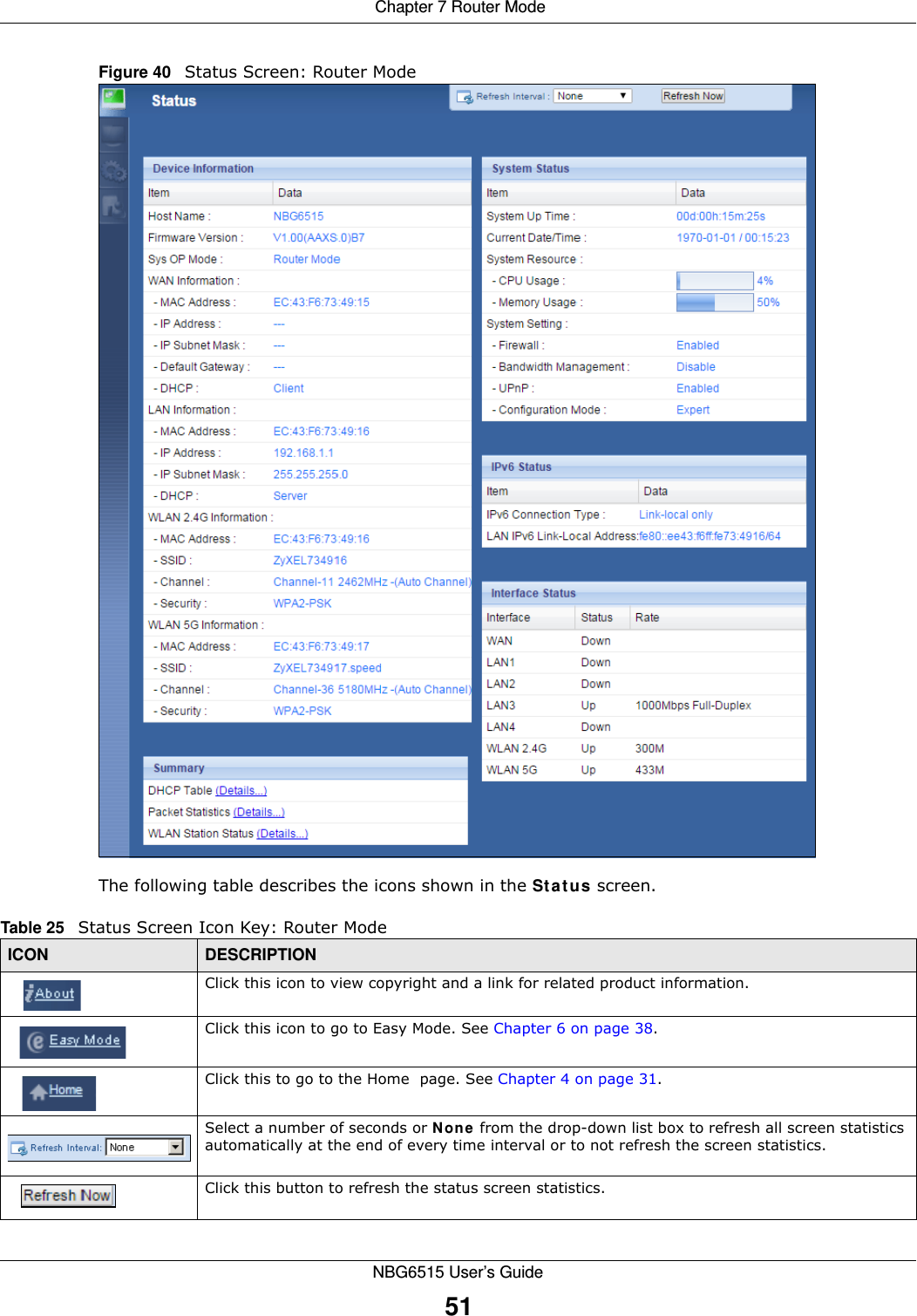
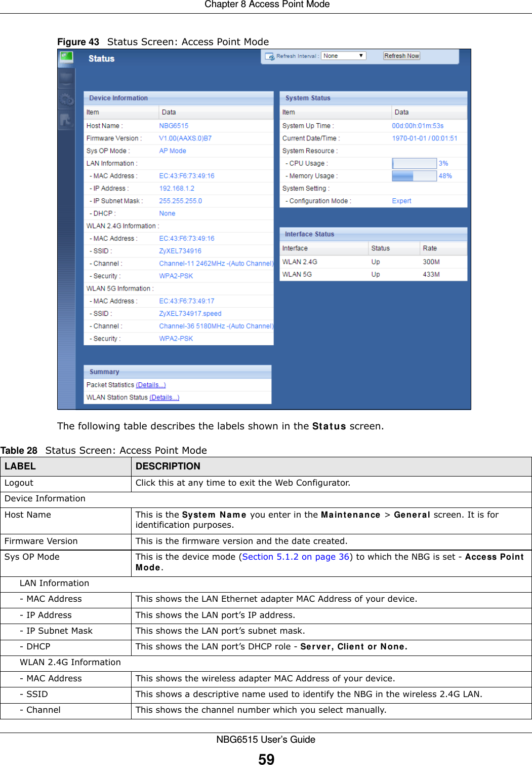
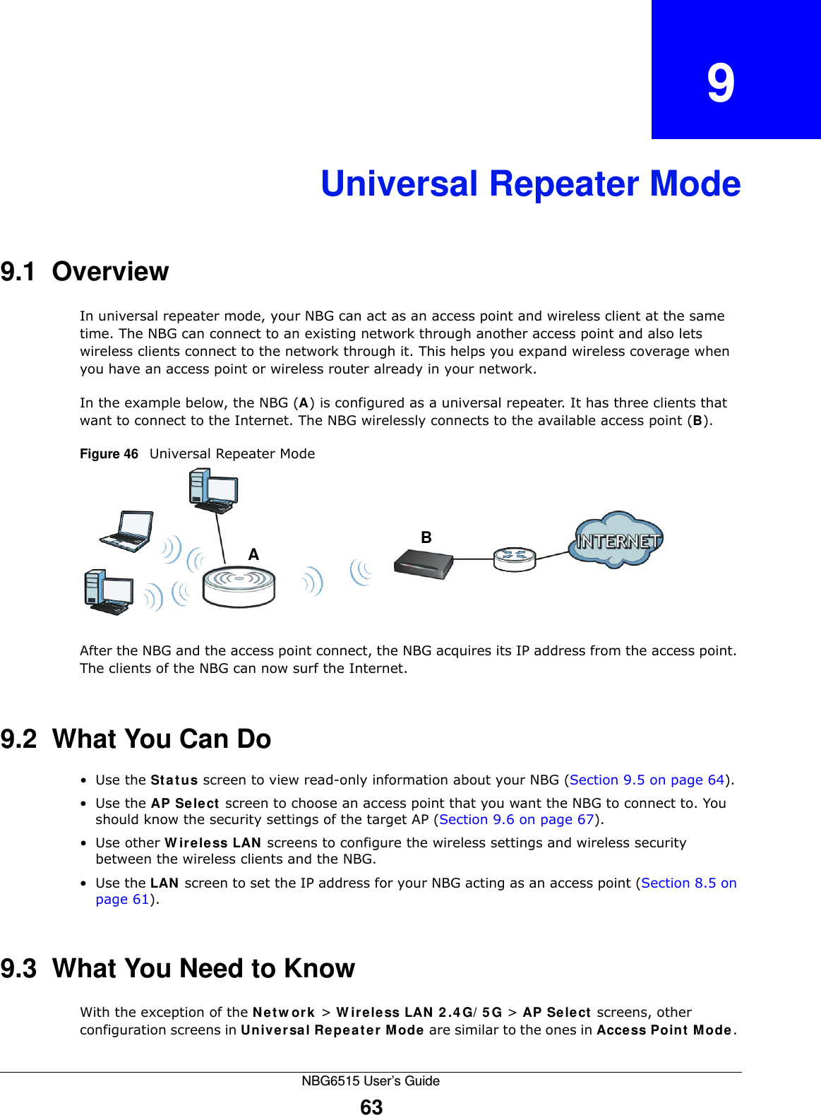
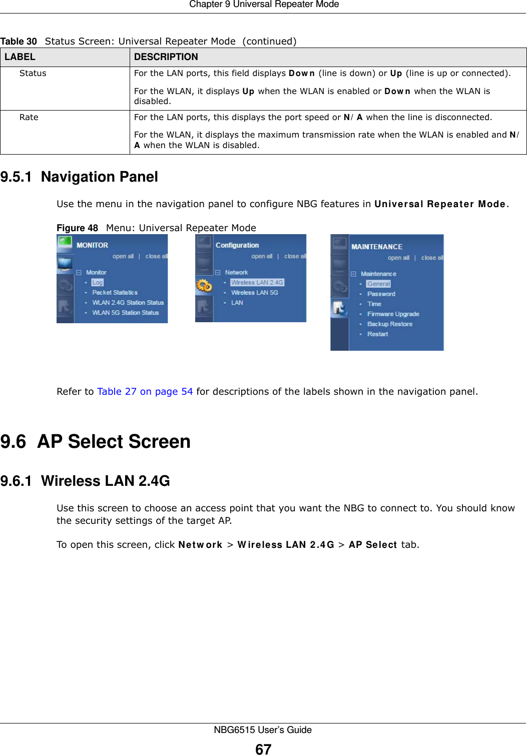
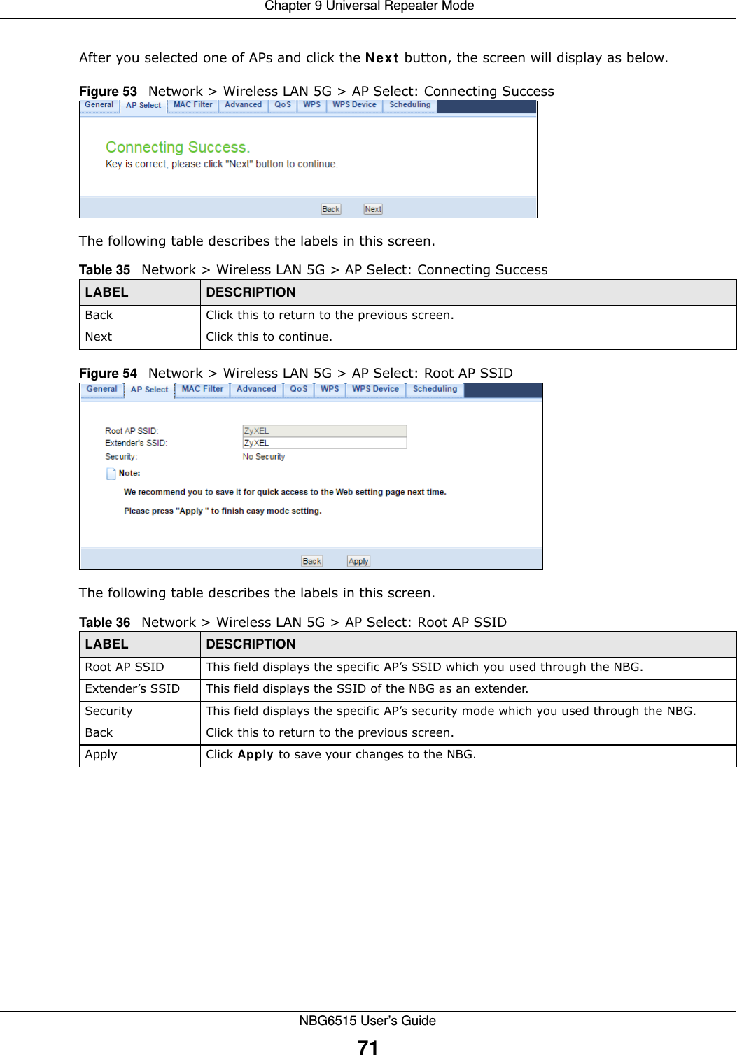
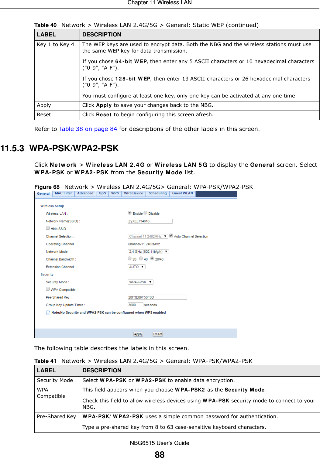
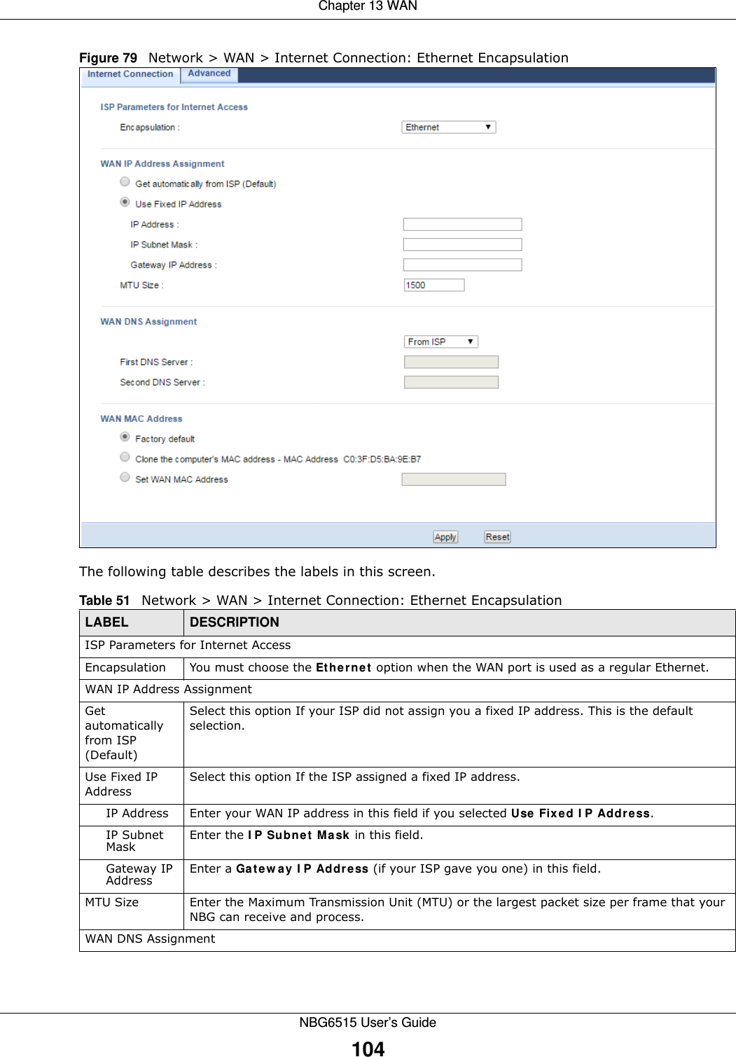
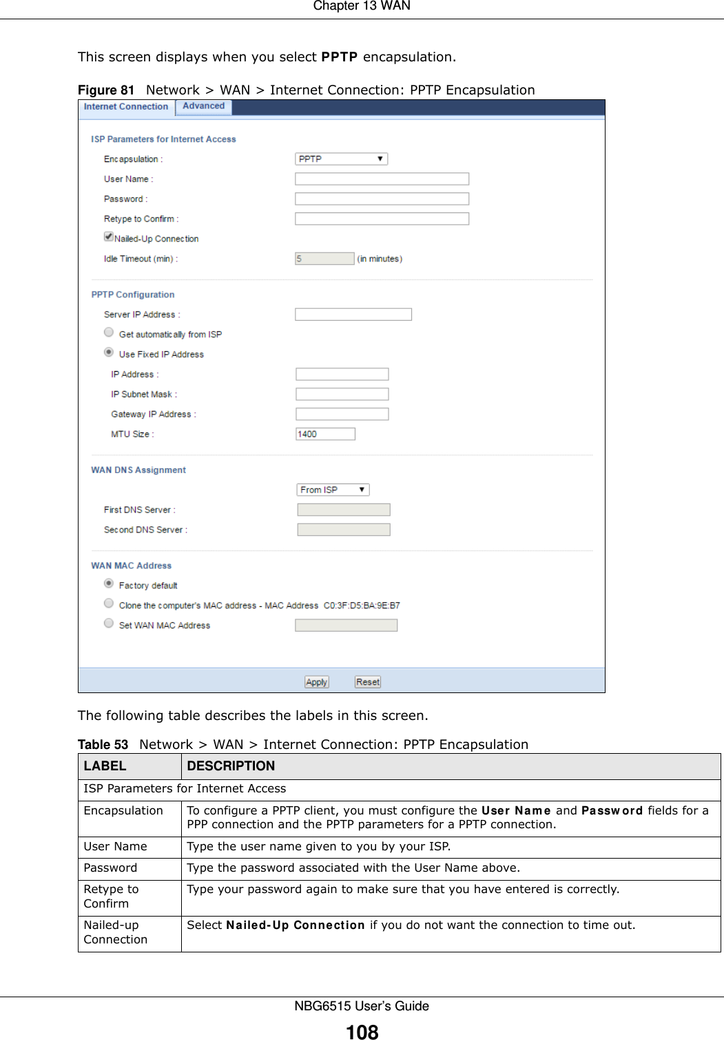
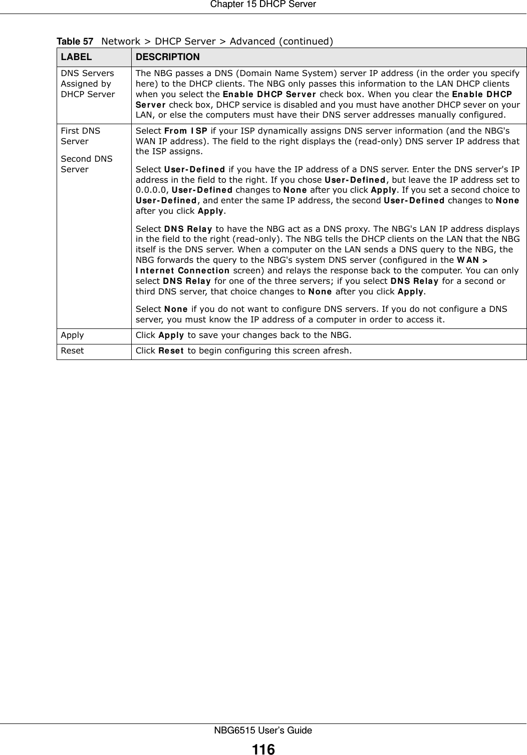
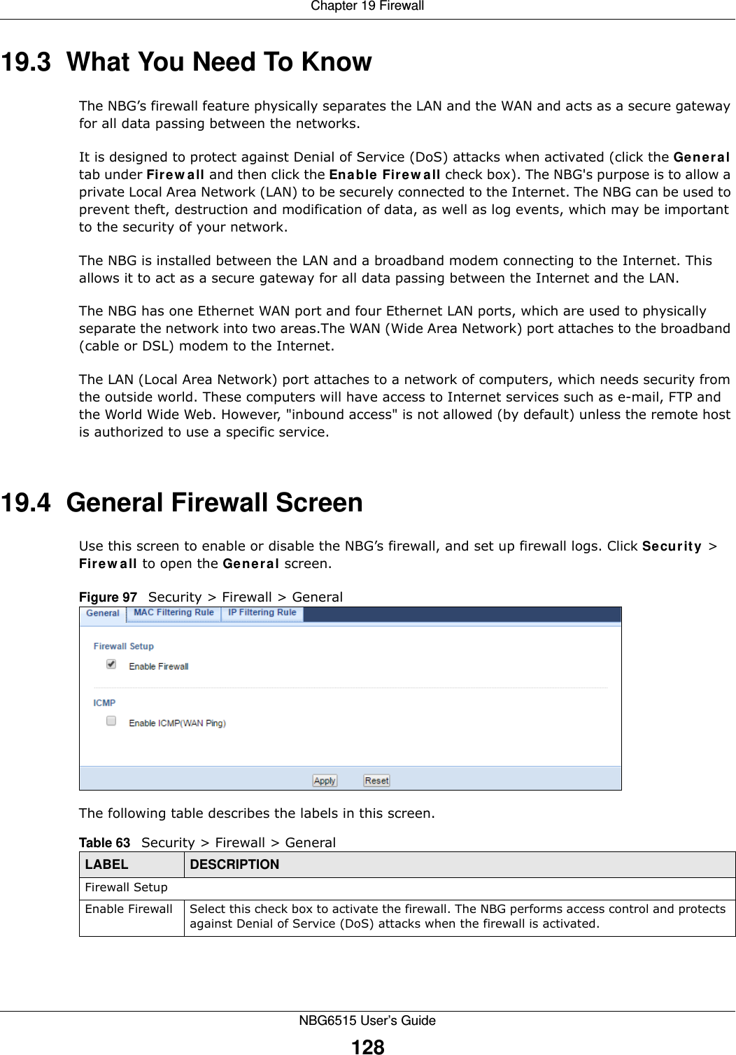
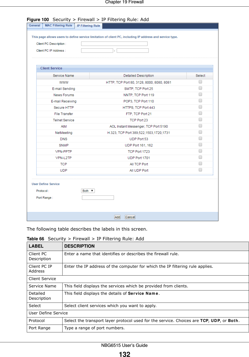
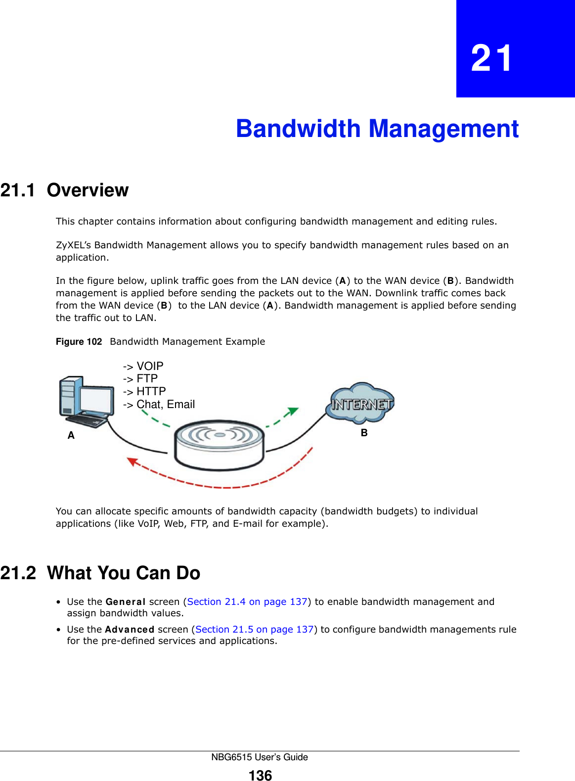
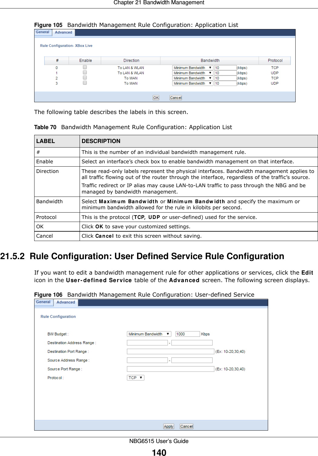
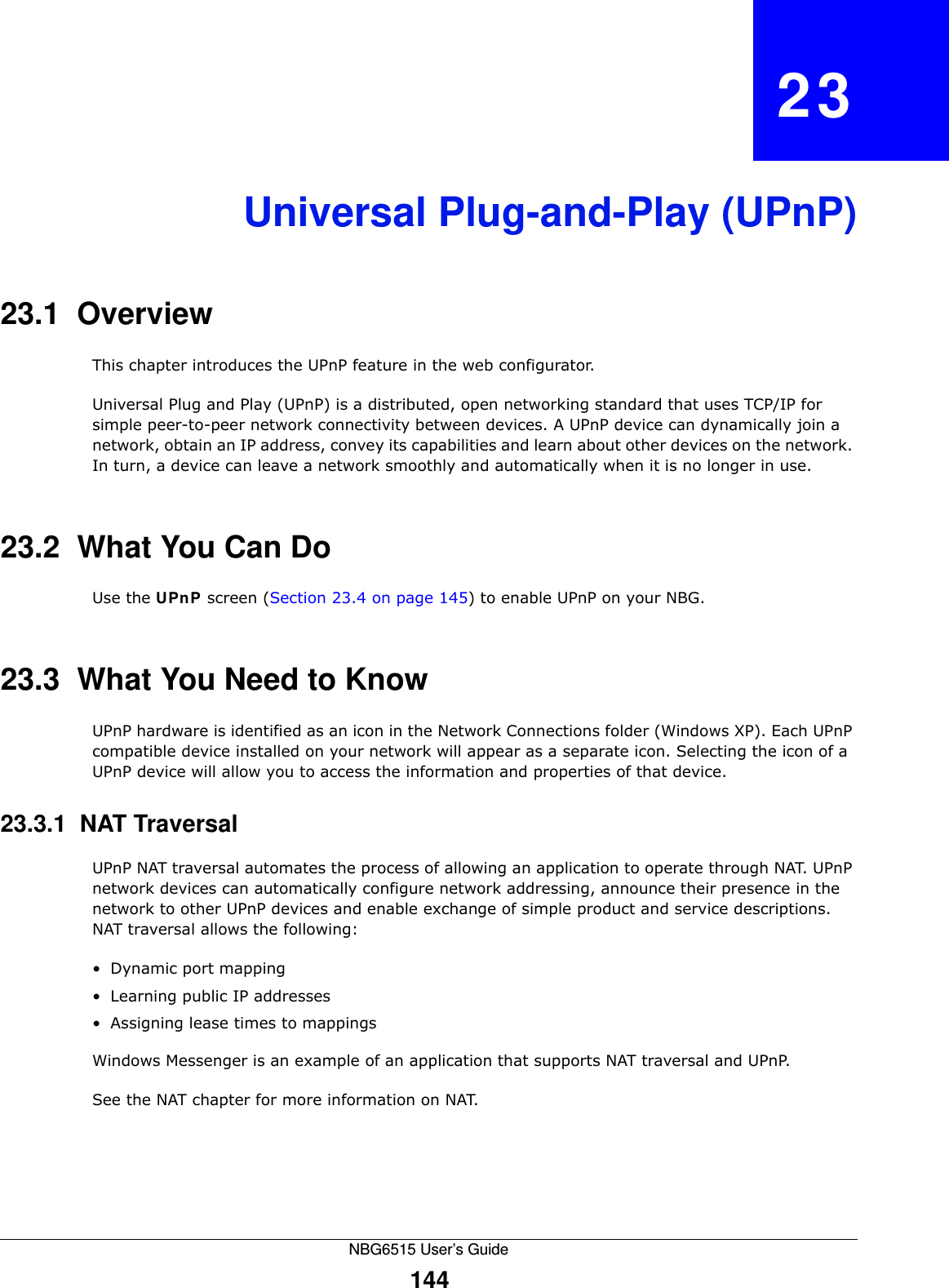
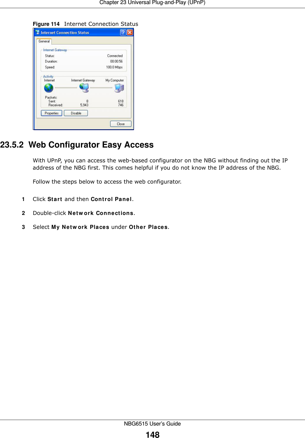
![Chapter 26 TroubleshootingNBG6515 User’s Guide1693Make sure your Internet browser does not block pop-up windows and has JavaScript and Java enabled. See Appendix A on page 173.4Make sure your computer is in the same subnet as the NBG. (If you know that there are routers between your computer and the NBG, skip this step.)• If there is a DHCP server on your network, make sure your computer is using a dynamic IP address. See Appendix C on page 191. • If there is no DHCP server on your network, make sure your computer’s IP address is in the same subnet as the NBG. See Appendix C on page 191.5Reset the device to its factory defaults, and try to access the NBG with the default IP address. See Section 3.3 on page 30.6If the problem continues, contact the network administrator or vendor, or try one of the advanced suggestions.Advanced Suggestion• If your computer is connected to the WAN port or is connected wirelessly, use a computer that is connected to a LAN/ETHERNET port.I can see the Login screen, but I cannot log in to the NBG.1Make sure you have entered the password correctly. The default password is 1234. This field is case-sensitive, so make sure [Caps Lock] is not on. 2This can happen when you fail to log out properly from your last session. Try logging in again after 5 minutes.3Disconnect and re-connect the power adaptor or cord to the NBG. 4If this does not work, you have to reset the device to its factory defaults. See Section 26.4 on page 171.26.3 Internet AccessI cannot access the Internet.1Check the hardware connections, and make sure the LEDs are behaving as expected. See the Quick Start Guide.2Make sure you entered your ISP account information correctly in the wizard. These fields are case-sensitive, so make sure [Caps Lock] is not on.](https://usermanual.wiki/ZyXEL-Communications/NBG6515.Users-Manual/User-Guide-2693921-Page-169.png)