ZyXEL Communications NBG6515 AC750 Dual band Wireless Gigabit Router User Manual Book
ZyXEL Communications Corporation AC750 Dual band Wireless Gigabit Router Book
UserManual.wiki
>
ZyXEL Communications
>
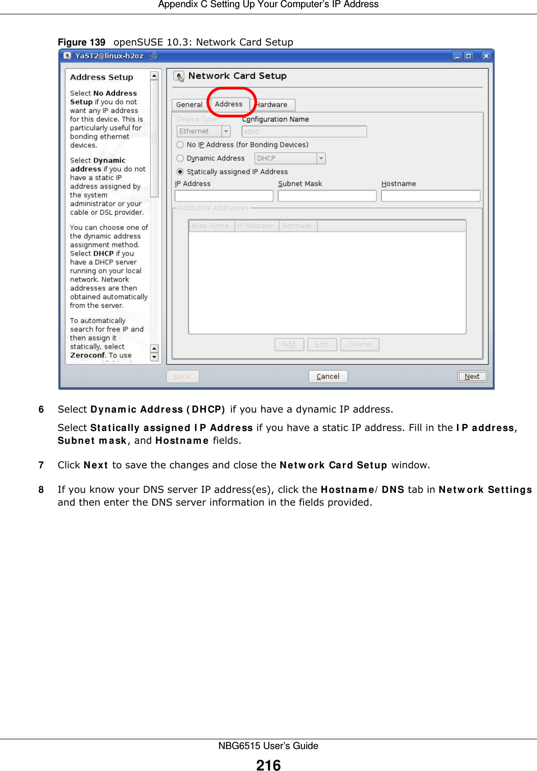
NBG6515 User Manual
>
Users Manual 2
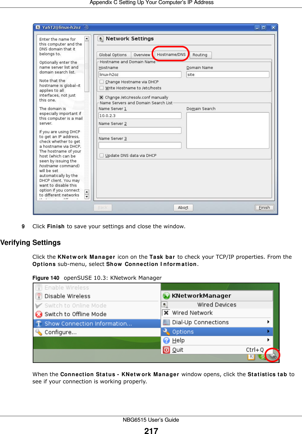
Contents
1.
Users Manual
2.
Users Manual 2
Users Manual 2
Navigation menu
Upload a User Manual
Namespaces
Wiki Guide
HTML
PDF
Info
Views
User Manual
Discussion / Help
Navigation
![Appendix C Setting Up Your Computer’s IP AddressNBG6515 User’s Guide1946Select Obt ain a n I P addre ss aut om at ica lly if your network administrator or ISP assigns your IP address dynamically.Select Use t h e follow ing I P Addre ss and fill in the I P a ddre ss, Subne t m ask, and D e fau lt ga t e w a y fields if you have a static IP address that was assigned to you by your network administrator or ISP. You may also have to enter a Pre fe r r e d D N S se rve r and an Alt e rn a t e DN S ser ver , if that information was provided.7Click OK to close the I nt erne t Prot ocol ( TCP/ I P) Proper t ie s window.8Click OK to close the Loca l Area Conn ect ion Pr oper t ies window.Verifying Settings1Click St a rt > All Pr ogra m s > Acce ssor ies > Com m a nd Pr om pt .2In the Com m a nd Pr om pt window, type "ipconfig" and then press [ENTER]. You can also go to St ar t > Cont r ol Pa n el > N e t w ork Conne ct ions, right-click a network connection, click St a t u s and then click the Suppor t tab to view your IP address and connection information.](https://usermanual.wiki/ZyXEL-Communications/NBG6515.Users-Manual-2/User-Guide-2693922-Page-21.png)
![Appendix C Setting Up Your Computer’s IP AddressNBG6515 User’s Guide1988Select Obt ain a n I P addre ss aut om at ica lly if your network administrator or ISP assigns your IP address dynamically.Select Use t h e follow ing I P Addre ss and fill in the I P a ddre ss, Subne t m ask, and D e fau lt ga t e w a y fields if you have a static IP address that was assigned to you by your network administrator or ISP. You may also have to enter a Pre fe r r e d D N S se rve r and an Alt e rn a t e DN S ser ver , if that information was provided.Click Adva nce d .9Click OK to close the I nt erne t Prot ocol ( TCP/ I P) Proper t ie s window.10 Click OK to close the Loca l Area Conn ect ion Pr oper t ies window.Verifying Settings1Click St a rt > All Pr ogra m s > Acce ssor ies > Com m a nd Pr om pt .2In the Com m a nd Pr om pt window, type "ipconfig" and then press [ENTER]. You can also go to St ar t > Cont r ol Pa n el > N e t w ork Conne ct ions, right-click a network connection, click St a t u s and then click the Suppor t tab to view your IP address and connection information.](https://usermanual.wiki/ZyXEL-Communications/NBG6515.Users-Manual-2/User-Guide-2693922-Page-25.png)
![Appendix C Setting Up Your Computer’s IP AddressNBG6515 User’s Guide2027Select Obt ain a n I P addre ss aut om at ica lly if your network administrator or ISP assigns your IP address dynamically.Select Use t h e follow ing I P Addre ss and fill in the I P a ddre ss, Subne t m ask, and D e fau lt ga t e w a y fields if you have a static IP address that was assigned to you by your network administrator or ISP. You may also have to enter a Pre fe r r e d D N S se rve r and an Alt e rn a t e DN S ser ver , if that information was provided. Click Adva nced if you want to configure advanced settings for IP, DNS and WINS. 8Click OK to close the I nt erne t Prot ocol ( TCP/ I P) Proper t ie s window.9Click OK to close the Loca l Area Conn ect ion Pr oper t ies window.Verifying Settings1Click St a rt > All Pr ogra m s > Acce ssor ies > Com m a nd Pr om pt .2In the Com m a nd Pr om pt window, type "ipconfig" and then press [ENTER]. 3The IP settings are displayed as follows.](https://usermanual.wiki/ZyXEL-Communications/NBG6515.Users-Manual-2/User-Guide-2693922-Page-29.png)