ZyXEL Communications NBG6515 AC750 Dual band Wireless Gigabit Router User Manual Book
ZyXEL Communications Corporation AC750 Dual band Wireless Gigabit Router Book
Contents
- 1. Users Manual
- 2. Users Manual 2
Users Manual 2

NBG6515 User’s Guide
174
APPENDIX A
IP Addresses and Subnetting
This appendix introduces IP addresses and subnet masks.
IP addresses identify individual devices on a network. Every networking device (including
computers, servers, routers, printers, etc.) needs an IP address to communicate across the
network. These networking devices are also known as hosts.
Subnet masks determine the maximum number of possible hosts on a network. You can also use
subnet masks to divide one network into multiple sub-networks.
Introduction to IP Addresses
One part of the IP address is the network number, and the other part is the host ID. In the same
way that houses on a street share a common street name, the hosts on a network share a common
network number. Similarly, as each house has its own house number, each host on the network has
its own unique identifying number - the host ID. Routers use the network number to send packets
to the correct network, while the host ID determines to which host on the network the packets are
delivered.
Structure
An IP address is made up of four parts, written in dotted decimal notation (for example,
192.168.1.1). Each of these four parts is known as an octet. An octet is an eight-digit binary
number (for example 11000000, which is 192 in decimal notation).
Therefore, each octet has a possible range of 00000000 to 11111111 in binary, or 0 to 255 in
decimal.
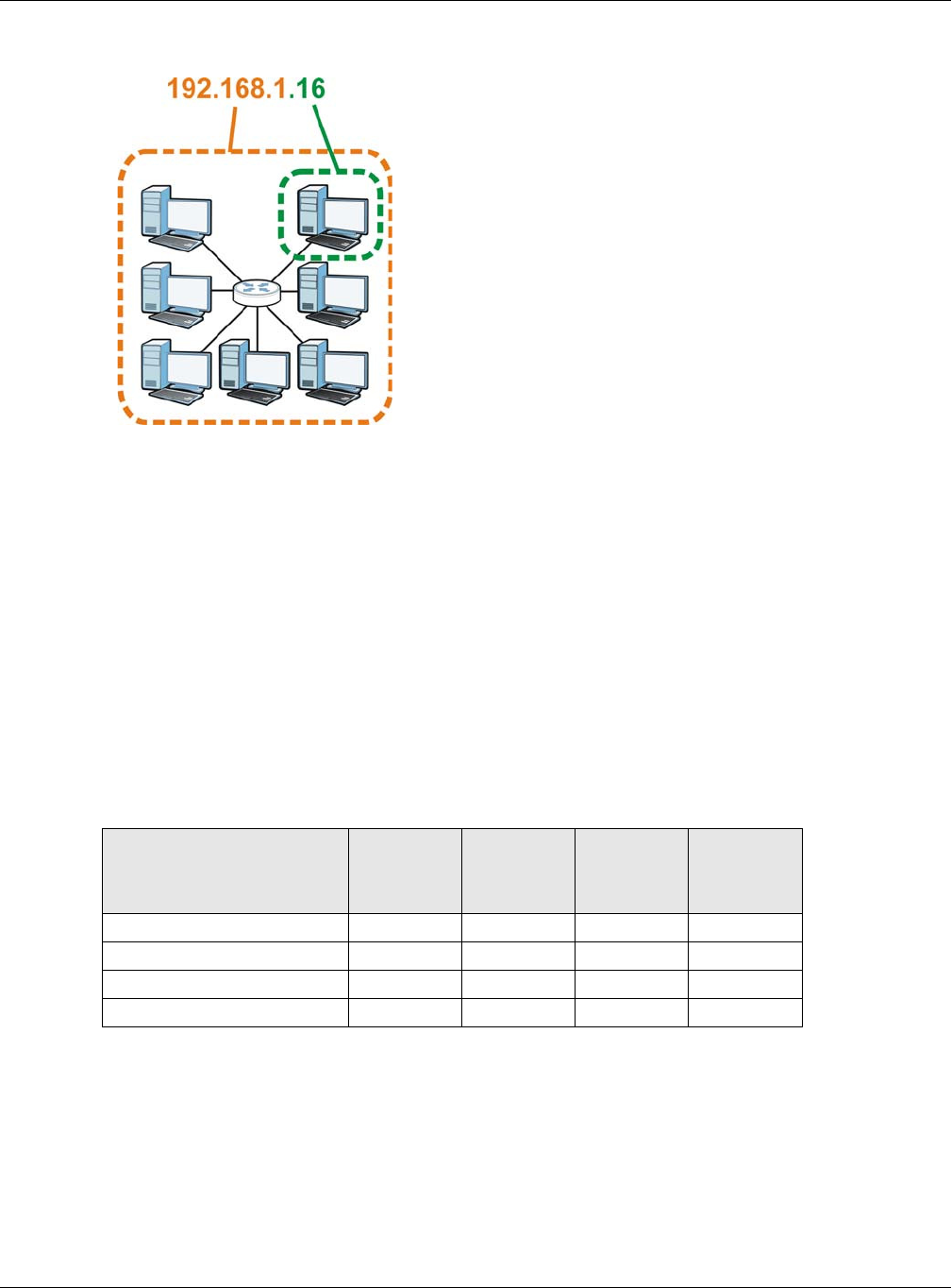
The following figure shows an example IP address in which the first three octets (192.168.1) are
the network number, and the fourth octet (16) is the host ID.
Appendix A IP Addresses and Subnetting
NBG6515 User’s Guide
175
Figure 130 Network Number and Host ID
How much of the IP address is the network number and how much is the host ID varies according
to the subnet mask.
Subnet Masks
A subnet mask is used to determine which bits are part of the network number, and which bits are
part of the host ID (using a logical AND operation). The term “subnet” is short for “sub-network”.
A subnet mask has 32 bits. If a bit in the subnet mask is a “1” then the corresponding bit in the IP
address is part of the network number. If a bit in the subnet mask is “0” then the corresponding bit
in the IP address is part of the host ID.
The following example shows a subnet mask identifying the network number (in bold text) and host
ID of an IP address (192.168.1.2 in decimal).
By convention, subnet masks always consist of a continuous sequence of ones beginning from the
leftmost bit of the mask, followed by a continuous sequence of zeros, for a total number of 32 bits.
Subnet masks can be referred to by the size of the network number part (the bits with a “1” value).
For example, an “8-bit mask” means that the first 8 bits of the mask are ones and the remaining 24
bits are zeroes.
Table 81 IP Address Network Number and Host ID Example
1ST OCTET:
(192)
2ND
OCTET:
(168)
3RD
OCTET:
(1)
4TH OCTET
(2)
IP Address (Binary) 11000000 10101000 00000001 00000010
Subnet Mask (Binary) 1 1 1 1 1 1 1 1 1 1 1 1 1 1 1 1 1 1 1 1 1 1 1 1 00000000
Network Number 1 1 0 0 0 0 0 0 1 0 1 0 1 0 0 0 0 0 0 0 0 0 0 1
Host ID 00000010
Appendix A IP Addresses and Subnetting
NBG6515 User’s Guide
176
Subnet masks are expressed in dotted decimal notation just like IP addresses. The following
examples show the binary and decimal notation for 8-bit, 16-bit, 24-bit and 29-bit subnet masks.
Network Size
The size of the network number determines the maximum number of possible hosts you can have
on your network. The larger the number of network number bits, the smaller the number of
remaining host ID bits.
An IP address with host IDs of all zeros is the IP address of the network (192.168.1.0 with a 24-bit
subnet mask, for example). An IP address with host IDs of all ones is the broadcast address for that
network (192.168.1.255 with a 24-bit subnet mask, for example).
As these two IP addresses cannot be used for individual hosts, calculate the maximum number of
possible hosts in a network as follows:
Notation
Since the mask is always a continuous number of ones beginning from the left, followed by a
continuous number of zeros for the remainder of the 32 bit mask, you can simply specify the
number of ones instead of writing the value of each octet. This is usually specified by writing a “/”
followed by the number of bits in the mask after the address.
For example, 192.1.1.0 /25 is equivalent to saying 192.1.1.0 with subnet mask 255.255.255.128.
The following table shows some possible subnet masks using both notations.
Table 82 Subnet Masks
BINARY
DECIMAL
1ST
OCTET
2ND
OCTET
3RD
OCTET 4TH OCTET
8-bit mask 11111111 00000000 00000000 00000000 255.0.0.0
16-bit mask 11111111 11111111 00000000 00000000 255.255.0.0
24-bit mask 11111111 11111111 11111111 00000000 255.255.255.0
29-bit mask 11111111 11111111 11111111 11111000 255.255.255.248
Table 83 Maximum Host Numbers
SUBNET MASK HOST ID SIZE MAXIMUM NUMBER OF
HOSTS
8 bits 255.0.0.0 24 bits 224 – 2 16777214
16 bits 255.255.0.0 16 bits 216 – 2 65534
24 bits 255.255.255.0 8 bits 28 – 2 254
29 bits 255.255.255.248 3 bits 23 – 2 6
Table 84 Alternative Subnet Mask Notation
SUBNET MASK ALTERNATIVE
NOTATION
LAST OCTET
(BINARY)
LAST OCTET
(DECIMAL)
255.255.255.0 /24 0000 0000 0
255.255.255.128 /25 1000 0000 128
255.255.255.192 /26 1100 0000 192
Appendix A IP Addresses and Subnetting
NBG6515 User’s Guide
177
Subnetting
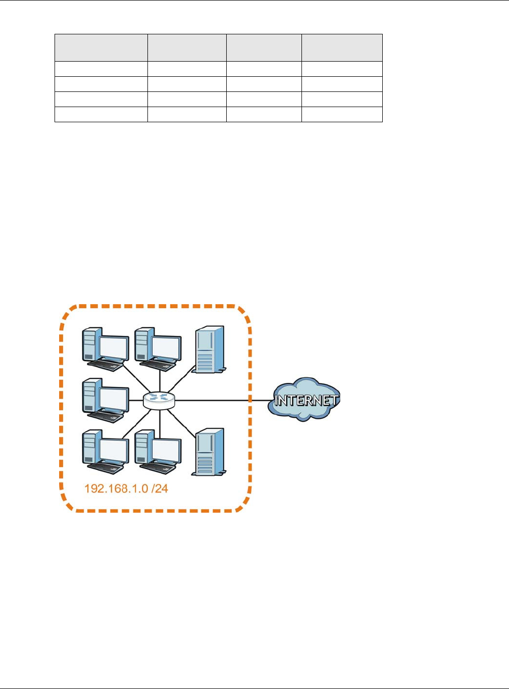
You can use subnetting to divide one network into multiple sub-networks. In the following example
a network administrator creates two sub-networks to isolate a group of servers from the rest of the
company network for security reasons.
In this example, the company network address is 192.168.1.0. The first three octets of the address
(192.168.1) are the network number, and the remaining octet is the host ID, allowing a maximum
of 28 – 2 or 254 possible hosts.
The following figure shows the company network before subnetting.
Figure 131 Subnetting Example: Before Subnetting
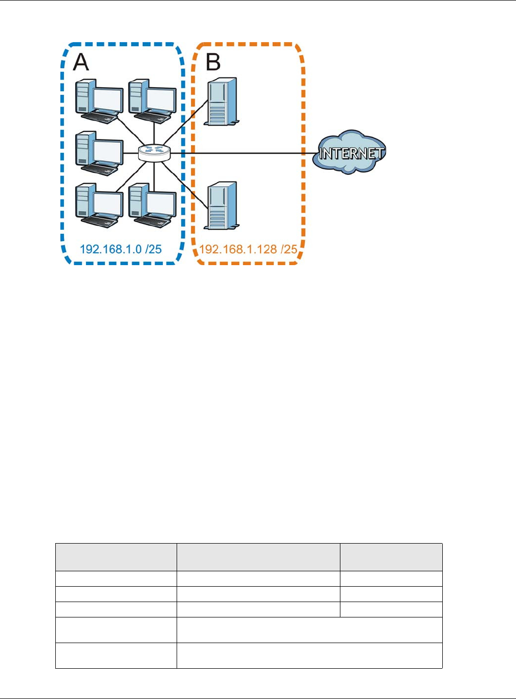
You can “borrow” one of the host ID bits to divide the network 192.168.1.0 into two separate sub-
networks. The subnet mask is now 25 bits (255.255.255.128 or /25).
The “borrowed” host ID bit can have a value of either 0 or 1, allowing two subnets; 192.168.1.0 /25
and 192.168.1.128 /25.
The following figure shows the company network after subnetting. There are now two sub-
networks, A and B.
255.255.255.224 /27 1110 0000 224
255.255.255.240 /28 1111 0000 240
255.255.255.248 /29 1111 1000 248
255.255.255.252 /30 1111 1100 252
Table 84 Alternative Subnet Mask Notation (continued)
SUBNET MASK ALTERNATIVE
NOTATION
LAST OCTET
(BINARY)
LAST OCTET
(DECIMAL)
Appendix A IP Addresses and Subnetting
NBG6515 User’s Guide
178
Figure 132 Subnetting Example: After Subnetting
In a 25-bit subnet the host ID has 7 bits, so each sub-network has a maximum of 27 – 2 or 126
possible hosts (a host ID of all zeroes is the subnet’s address itself, all ones is the subnet’s
broadcast address).
192.168.1.0 with mask 255.255.255.128 is subnet A itself, and 192.168.1.127 with mask
255.255.255.128 is its broadcast address. Therefore, the lowest IP address that can be assigned to
an actual host for subnet A is 192.168.1.1 and the highest is 192.168.1.126.
Similarly, the host ID range for subnet B is 192.168.1.129 to 192.168.1.254.
Example: Four Subnets
The previous example illustrated using a 25-bit subnet mask to divide a 24-bit address into two
subnets. Similarly, to divide a 24-bit address into four subnets, you need to “borrow” two host ID
bits to give four possible combinations (00, 01, 10 and 11). The subnet mask is 26 bits
(11111111.11111111.11111111.1 1 000000) or 255.255.255.192.
Each subnet contains 6 host ID bits, giving 26 - 2 or 62 hosts for each subnet (a host ID of all
zeroes is the subnet itself, all ones is the subnet’s broadcast address).
Table 85 Subnet 1
IP/SUBNET MASK NETWORK NUMBER LAST OCTET BIT
VALUE
IP Address (Decimal) 192.168.1. 0
IP Address (Binary) 11000000.10101000.00000001. 0 0 000000
Subnet Mask (Binary) 11111111.11111111.11111111. 1 1 000000
Subnet Address:
192.168.1.0
Lowest Host ID: 192.168.1.1
Broadcast Address:
192.168.1.63
Highest Host ID: 192.168.1.62

Appendix A IP Addresses and Subnetting
NBG6515 User’s Guide
179
Example: Eight Subnets
Similarly, use a 27-bit mask to create eight subnets (000, 001, 010, 011, 100, 101, 110 and 111).
The following table shows IP address last octet values for each subnet.
Table 86 Subnet 2
IP/SUBNET MASK NETWORK NUMBER LAST OCTET BIT
VALUE
IP Address 192.168.1. 64
IP Address (Binary) 11000000.10101000.00000001. 0 1 000000
Subnet Mask (Binary) 11111111.11111111.11111111. 1 1 000000
Subnet Address:
192.168.1.64
Lowest Host ID: 192.168.1.65
Broadcast Address:
192.168.1.127
Highest Host ID: 192.168.1.126
Table 87 Subnet 3
IP/SUBNET MASK NETWORK NUMBER LAST OCTET BIT
VALUE
IP Address 192.168.1. 128
IP Address (Binary) 11000000.10101000.00000001. 1 0 000000
Subnet Mask (Binary) 11111111.11111111.11111111. 1 1 000000
Subnet Address:
192.168.1.128
Lowest Host ID: 192.168.1.129
Broadcast Address:
192.168.1.191
Highest Host ID: 192.168.1.190
Table 88 Subnet 4
IP/SUBNET MASK NETWORK NUMBER LAST OCTET BIT
VALUE
IP Address 192.168.1. 192
IP Address (Binary) 11000000.10101000.00000001. 1 1 000000
Subnet Mask (Binary) 11111111.11111111.11111111. 1 1 000000
Subnet Address:
192.168.1.192
Lowest Host ID: 192.168.1.193
Broadcast Address:
192.168.1.255
Highest Host ID: 192.168.1.254
Table 89 Eight Subnets
SUBNET SUBNET
ADDRESS FIRST ADDRESS LAST
ADDRESS
BROADCAST
ADDRESS
1 0 1 30 31
232 33 62 63
364 65 94 95
496 97 126 127
5128 129 158 159
6160 161 190 191

Appendix A IP Addresses and Subnetting
NBG6515 User’s Guide
180
Subnet Planning
The following table is a summary for subnet planning on a network with a 24-bit network number.
The following table is a summary for subnet planning on a network with a 16-bit network number.
7192 193 222 223
8224 225 254 255
Table 89 Eight Subnets (continued)
SUBNET SUBNET
ADDRESS FIRST ADDRESS LAST
ADDRESS
BROADCAST
ADDRESS
Table 90 24-bit Network Number Subnet Planning
NO. “BORROWED”
HOST BITS SUBNET MASK NO. SUBNETS NO. HOSTS PER
SUBNET
1255.255.255.128 (/25) 2126
2255.255.255.192 (/26) 462
3255.255.255.224 (/27) 830
4255.255.255.240 (/28) 16 14
5255.255.255.248 (/29) 32 6
6255.255.255.252 (/30) 64 2
7255.255.255.254 (/31) 128 1
Table 91 16-bit Network Number Subnet Planning
NO. “BORROWED”
HOST BITS SUBNET MASK NO. SUBNETS NO. HOSTS PER
SUBNET
1255.255.128.0 (/17) 232766
2255.255.192.0 (/18) 416382
3255.255.224.0 (/19) 88190
4255.255.240.0 (/20) 16 4094
5255.255.248.0 (/21) 32 2046
6255.255.252.0 (/22) 64 1022
7255.255.254.0 (/23) 128 510
8255.255.255.0 (/24) 256 254
9255.255.255.128 (/25) 512 126
10 255.255.255.192 (/26) 1024 62
11 255.255.255.224 (/27) 2048 30
12 255.255.255.240 (/28) 4096 14
13 255.255.255.248 (/29) 8192 6
14 255.255.255.252 (/30) 16384 2
15 255.255.255.254 (/31) 32768 1

Appendix A IP Addresses and Subnetting
NBG6515 User’s Guide
181
Configuring IP Addresses
Where you obtain your network number depends on your particular situation. If the ISP or your
network administrator assigns you a block of registered IP addresses, follow their instructions in
selecting the IP addresses and the subnet mask.
If the ISP did not explicitly give you an IP network number, then most likely you have a single user
account and the ISP will assign you a dynamic IP address when the connection is established. If this
is the case, it is recommended that you select a network number from 192.168.0.0 to
192.168.255.0. The Internet Assigned Number Authority (IANA) reserved this block of addresses
specifically for private use; please do not use any other number unless you are told otherwise. You
must also enable Network Address Translation (NAT) on the NBG.
Once you have decided on the network number, pick an IP address for your NBG that is easy to
remember (for instance, 192.168.1.1) but make sure that no other device on your network is using
that IP address.
The subnet mask specifies the network number portion of an IP address. Your NBG will compute the
subnet mask automatically based on the IP address that you entered. You don't need to change the
subnet mask computed by the NBG unless you are instructed to do otherwise.
Private IP Addresses
Every machine on the Internet must have a unique address. If your networks are isolated from the
Internet (running only between two branch offices, for example) you can assign any IP addresses to
the hosts without problems. However, the Internet Assigned Numbers Authority (IANA) has
reserved the following three blocks of IP addresses specifically for private networks:
• 10.0.0.0 — 10.255.255.255
• 172.16.0.0 — 172.31.255.255
• 192.168.0.0 — 192.168.255.255
You can obtain your IP address from the IANA, from an ISP, or it can be assigned from a private
network. If you belong to a small organization and your Internet access is through an ISP, the ISP
can provide you with the Internet addresses for your local networks. On the other hand, if you are
part of a much larger organization, you should consult your network administrator for the
appropriate IP addresses.
Regardless of your particular situation, do not create an arbitrary IP address; always follow the
guidelines above. For more information on address assignment, please refer to RFC 1597, Address
Allocation for Private Internets and RFC 1466, Guidelines for Management of IP Address Space.
IP Address Conflicts
Each device on a network must have a unique IP address. Devices with duplicate IP addresses on
the same network will not be able to access the Internet or other resources. The devices may also
be unreachable through the network.
Conflicting Computer IP Addresses Example
More than one device can not use the same IP address. In the following example computer A has a
static (or fixed) IP address that is the same as the IP address that a DHCP server assigns to
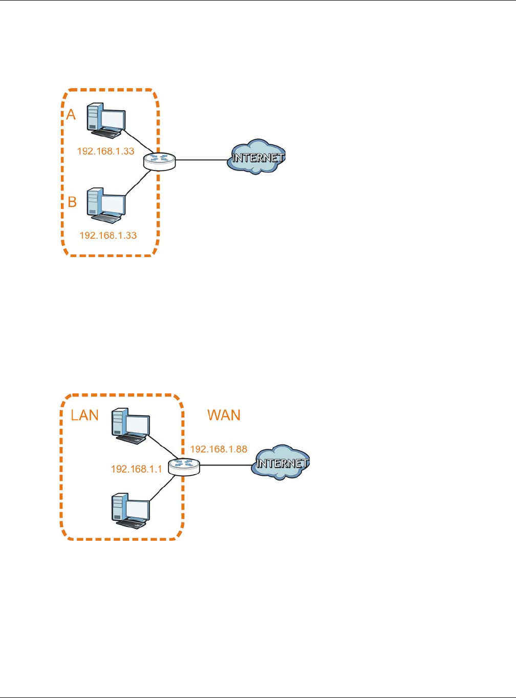
Appendix A IP Addresses and Subnetting
NBG6515 User’s Guide
182
computer B which is a DHCP client. Neither can access the Internet. This problem can be solved by
assigning a different static IP address to computer A or setting computer A to obtain an IP address
automatically.
Figure 133 Conflicting Computer IP Addresses Example
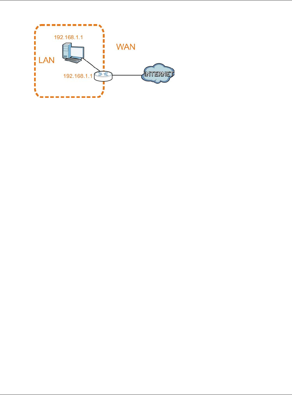
Conflicting Router IP Addresses Example
Since a router connects different networks, it must have interfaces using different network
numbers. For example, if a router is set between a LAN and the Internet (WAN), the router’s LAN
and WAN addresses must be on different subnets. In the following example, the LAN and WAN are
on the same subnet. The LAN computers cannot access the Internet because the router cannot
route between networks.
Figure 134 Conflicting Router IP Addresses Example
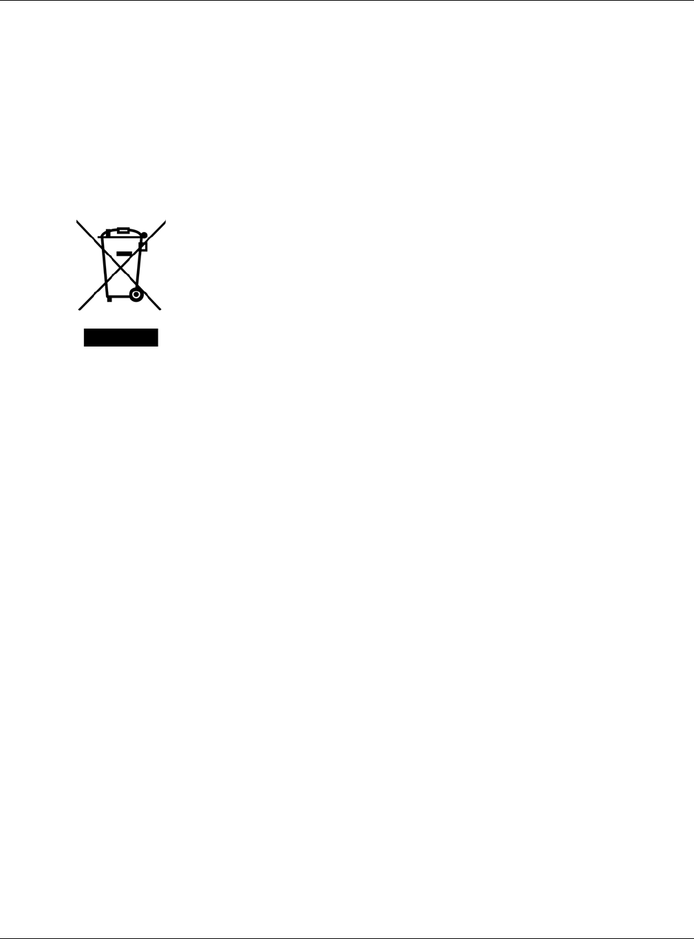
Conflicting Computer and Router IP Addresses Example
More than one device can not use the same IP address. In the following example, the computer and
the router’s LAN port both use 192.168.1.1 as the IP address. The computer cannot access the
Internet. This problem can be solved by assigning a different IP address to the computer or the
router’s LAN port.
Appendix A IP Addresses and Subnetting
NBG6515 User’s Guide
183
Figure 135 Conflicting Computer and Router IP Addresses Example

NBG6515 User’s Guide
184
APPENDIX B
Legal Information
Copyright
Copyright © 2015 by ZyXEL Communications Corporation.
The contents of this publication may not be reproduced in any part or as a whole, transcribed, stored in a retrieval system, translated into
any language, or transmitted in any form or by any means, electronic, mechanical, magnetic, optical, chemical, photocopying, manual, or
otherwise, without the prior written permission of ZyXEL Communications Corporation.
Published by ZyXEL Communications Corporation. All rights reserved.
Disclaimers
ZyXEL does not assume any liability arising out of the application or use of any products, or software described herein. Neither does it
convey any license under its patent rights nor the patent rights of others. ZyXEL further reserves the right to make changes in any
products described herein without notice. This publication is subject to change without notice.
Your use of the NBG is subject to the terms and conditions of any related service providers.
Trademarks
Trademarks mentioned in this publication are used for identification purposes only and may be properties of their respective owners.
Regulatory Notice and Statement
UNITED STATES OF AMERICA
The following information applies if you use the product within USA area.
FCC EMC Statement
• This device complies with part 15 of the FCC Rules. Operation is subject to the following two conditions:
1This device may not cause harmful interference, and
2this device must accept any interference received, including interference that may cause undesired operation.
• Changes or modifications not expressly approved by the party responsible for compliance could void the user's authority to operate the
equipment.
• This product has been tested and complies with the specifications for a Class B digital device, pursuant to Part 15 of the FCC Rules.
These limits are designed to provide reasonable protection against harmful interference in a residential installation. This equipment
generates, uses, and can radiate radio frequency energy and, if not installed and used according to the instructions, may cause
harmful interference to radio communications. However, there is no guarantee that interference will not occur in a particular
installation.
• If this equipment does cause harmful interference to radio or television reception, which is found by turning the equipment off and on,
the user is encouraged to try to correct the interference by one or more of the following measures:
1Reorient or relocate the receiving antenna.
2Increase the separation between the equipment or devices.
3Connect the equipment to an outlet other than the receiver's.
4Consult a dealer or an experienced radio/TV technician for assistance.
FCC Radiation Exposure Statement
• This equipment complies with FCC RF radiation exposure limits set forth for an uncontrolled environment.
• This transmitter must be at least 20 cm from the user and must not be co-located or operating in conjunction with any other antenna
or transmitter.
CANADA
The following information applies if you use the product within Canada area.
Industry Canada ICES statement
CAN ICES-3 (B)/NMB-3(B)

Appendix B Legal Information
NBG6515 User’s Guide
185
Industry Canada RSS-GEN & RSS-210 statement
• This device complies with Industry Canada’s licence-exempt RSSs. Operation is subject to the following two conditions:(1) This device
may not cause interference; and (2) This device must accept any interference, including interference that may cause undesired
operation of the device.
• This radio transmitter (2468C-NBG6515) has been approved by Industry Canada to operate with the antenna types listed below with
the maximum permissible gain and required antenna impedance for each antenna type indicated. Antenna types not included in this
list, having a gain greater than the maximum gain indicated for that type, are strictly prohibited for use with this device.
• If you use the produce with 5G wireless function, the following attention shall be paid that,
(i) the device for operation is only for indoor use to reduce the potential for harmful interference to co-channel mobile satellite systems;
(ii) the maximum antenna gain permitted for devices in the bands 5470-5725 MHz shall comply with the e.i.r.p. limit; and
(iii) the maximum antenna gain permitted for devices in the band 5725-5825 MHz shall comply with the e.i.r.p. limits specified for point-
to-point and non point-to-point operation as appropriate.
• Le présent appareil est conforme aux CNR d’Industrie Canada applicables aux appareils radio exempts de licence. L’exploitation est
autorisée aux deux conditions suivantes : (1) l’appareil ne doit pas produire de brouillage; (2) l’utilisateur de l’appareil doit accepter
tout brouillage radioélectrique subi, même si le brouillage est susceptible d’en compromettre le fonctionnement.
• Le présent émetteur radio (2468C-NBG6515) de modèle s'il fait partie du matériel de catégorieI) a été approuvé par Industrie Canada
pour fonctionner avec les types d'antenne énumérés ci-dessous et ayant un gain admissible maximal et l'impédance requise pour
chaque type d'antenne. Les types d'antenne non inclus dans cette liste, ou dont le gain est supérieur au gain maximal indiqué, sont
strictement interdits pour l'exploitation de l'émetteur.
• Si vous utilisez le produit avec 5G sans fil fonction, suivant l'attention doit être versée que,
(i) les dispositifs fonctionnant sont réservés uniquement pour une utilisation à l’intérieur afin de réduire les risques de brouillage
préjudiciable aux systèmes de satellites mobiles utilisant les mêmes canaux;
(ii) le gain maximal d’antenne permis pour les dispositifs utilisant les bandes et 5470-5725 MHz doit se conformer à la limite de p.i.r.e.;
(iii) le gain maximal d’antenne permis (pour les dispositifs utilisant la bande 5725-5825 MHz) doit se conformer à la limite de p.i.r.e.
spécifiée pour l’exploitation point à point et non point à point, selon le cas.
Industry Canada radiation exposure statement
This equipment complies with IC radiation exposure limits set forth for an uncontrolled environment. This equipment should be installed
and operated with a minimum distance of 20cm between the radiator and your body.
Déclaration d’exposition aux radiations:
Cet équipement est conforme aux limites d’exposition aux rayonnements IC établies pour un environnement non contrôlé.Cet équipement
doit être installé et utilisé avec un minimum de 20 cm de distance entre la source de rayonnement et votre corps.
EUROPEAN UNION
The following information applies if you use the product within the European Union.
Declaration of Conformity with Regard to EU Directive 1999/5/EC (R&TTE Directive)
Compliance information for 2.4GHz and/or 5GHz wireless products relevant to the EU and other Countries following the EU Directive 1999/
5/EC (R&TTE).
Б
(Bulgarian) С я ZyXEL , ч я
1999/5/C.
Español
(Spanish) Por medio de la presente ZyXEL declara que el equipo cumple con los requisitos esenciales y cualesquiera otras
disposiciones aplicables o exigibles de la Directiva 1999/5/CE.
Čeština
(Czech) ZyXEL tímto prohlašuje, že tento zařízení je ve shodě se základními požadavky a dalšími příslušnými ustanoveními
směrnice 1999/5/EC.
Dansk (Danish) Undertegnede ZyXEL erklærer herved, at følgende udstyr udstyr overholder de væsentlige krav og øvrige relevante
krav i direktiv 1999/5/EF.
Deutsch
(German) Hiermit erklärt ZyXEL, dass sich das Gerät Ausstattung in Übereinstimmung mit den grundlegenden Anforderungen
und den übrigen einschlägigen Bestimmungen der Richtlinie 1999/5/EU befindet.
Eesti keel
(Estonian) Käesolevaga kinnitab ZyXEL seadme seadmed vastavust direktiivi 1999/5/EÜ põhinõuetele ja nimetatud direktiivist
tulenevatele teistele asjakohastele sätetele.
Εηά
(Greek) Ε Η ΑΑ ZyXEL ∆ΗΩΕ επσός ΦΩΕΑ Ω∆Ε ΑΑΗΕ Α
Ε ΧΕΕ ∆ΑΑΕ Η ∆ΗΓΑ 1999/5/ΕC.
English Hereby, ZyXEL declares that this equipment is in compliance with the essential requirements and other relevant
provisions of Directive 1999/5/EC.
Français
(French) Par la présente ZyXEL déclare que l'appareil équipements est conforme aux exigences essentielles et aux autres
dispositions pertinentes de la directive 1999/5/EC.
Hrvatski
(Croatian) ZyXEL ovime izjavljuje da je radijska oprema tipa u skladu s Direktivom 1999/5/EC.

Appendix B Legal Information
NBG6515 User’s Guide
186
National Restrictions
This product may be used in all EU countries (and other countries following the EU Directive 2014/53/EU) without any limitation except for
the countries mentioned below:
Ce produit peut être utilisé dans tous les pays de l’UE (et dans tous les pays ayant transposés la directive 2014/53/UE) sans aucune
limitation, excepté pour les pays mentionnés ci-dessous:
Questo prodotto è utilizzabile in tutte i paesi EU (ed in tutti gli altri paesi che seguono le direttiva 2014/53/UE) senza nessuna limitazione,
eccetto per i paesii menzionati di seguito:
Das Produkt kann in allen EU Staaten ohne Einschränkungen eingesetzt werden (sowie in anderen Staaten die der Richtlinie 2014/53/EU
folgen) mit Außnahme der folgenden aufgeführten Staaten:
In the majority of the EU and other European countries, the 2.4GHz and 5GHz bands have been made available for the use of wireless
local area networks (LANs). Later in this document you will find an overview of countries in which additional restrictions or requirements
or both are applicable.
The requirements for any country may evolve. ZyXEL recommends that you check with the local authorities for the latest status of their
national regulations for both the 2.4GHz and 5GHz wireless LANs.
The following countries have restrictions and/or requirements in addition to those given in the table labeled “Overview of Regulat ory
Requirem ents for Wireless LANs”:.
Belgium
The Belgian Institute for Postal Services and Telecommunications (BIPT) must be notified of any outdoor wireless link having a range
exceeding 300 meters. Please check http://www.bipt.be for more details.
Draadloze verbindingen voor buitengebruik en met een reikwijdte van meer dan 300 meter dienen aangemeld te worden bij het Belgisch
Instituut voor postdiensten en telecommunicatie (BIPT). Zie http://www.bipt.be voor meer gegevens.
Les liaisons sans fil pour une utilisation en extérieur d’une distance supérieure à 300 mètres doivent être notifiées à l’Institut Belge des
services Postaux et des Télécommunications (IBPT). Visitez http://www.ibpt.be pour de plus amples détails.
Denmark
In Denmark, the band 5150 - 5350 MHz is also allowed for outdoor usage.
I Danmark må frekvensbåndet 5150 - 5350 også anvendes udendørs.
Italy
This product meets the National Radio Interface and the requirements specified in the National Frequency Allocation Table for Italy. Unless
this wireless LAN product is operating within the boundaries of the owner's property, its use requires a “general authorization.” Please
check http://www.sviluppoeconomico.gov.it/ for more details.
Questo prodotto è conforme alla specifiche di Interfaccia Radio Nazionali e rispetta il Piano Nazionale di ripartizione delle frequenze in
Italia. Se non viene installato all 'interno del proprio fondo, l'utilizzo di prodotti Wireless LAN richiede una “Autorizzazione Generale”.
Consultare http://www.sviluppoeconomico.gov.it/ per maggiori dettagli.
Latvia
Íslenska
(Icelandic) Hér með lýsir, ZyXEL því yfir að þessi búnaður er í samræmi við grunnkröfur og önnur viðeigandi ákvæði tilskipunar
1999/5/EC.
Italiano
(Italian) Con la presente ZyXEL dichiara che questo attrezzatura è conforme ai requisiti essenziali ed alle altre disposizioni
pertinenti stabilite dalla direttiva 1999/5/CE.
Latviešu valoda
(Latvian) Ar šo ZyXEL deklarē, ka iekārtas atbilst Direktīvas 1999/5/EK būtiskajām prasībām un citiem ar to saistītajiem
noteikumiem.
Lietuvių kalba
(Lithuanian) Šiuo ZyXEL deklaruoja, kad šis įranga atitinka esminius reikalavimus ir kitas 1999/5/EB Direktyvos nuostatas.
Magyar
(Hungarian) Alulírott, ZyXEL nyilatkozom, hogy a berendezés megfelel a vonatkozó alapvetõ követelményeknek és az 1999/5/EK
irányelv egyéb elõírásainak.
Malti (Maltese) Hawnhekk, ZyXEL, jiddikjara li dan tagħmir jikkonforma mal-ħtiġijiet essenzjali u ma provvedimenti oħrajn relevanti li
hemm fid-Dirrettiva 1999/5/EC.
Nederlands
(Dutch) Hierbij verklaart ZyXEL dat het toestel uitrusting in overeenstemming is met de essentiële eisen en de andere
relevante bepalingen van richtlijn 1999/5/EC.
Polski (Polish) Niniejszym ZyXEL oświadcza, że sprzęt jest zgodny z zasadniczymi wymogami oraz pozostałymi stosownymi
postanowieniami Dyrektywy 1999/5/EC.
Português
(Portuguese) ZyXEL declara que este equipamento está conforme com os requisitos essenciais e outras disposições da Directiva
1999/5/EC.
Română
(Romanian) Prin prezenta, ZyXEL declară că acest echipament este în conformitate cu cerinţele esenţiale şi alte prevederi
relevante ale Directivei 1999/5/EC.
Slovenčina
(Slovak) ZyXEL týmto vyhlasuje, že zariadenia spĺňa základné požiadavky a všetky príslušné ustanovenia Smernice 1999/5/EC.
Slovenščina
(Slovene) ZyXEL izjavlja, da je ta oprema v skladu z bistvenimi zahtevami in ostalimi relevantnimi določili direktive 1999/5/EC.
Suomi
(Finnish) ZyXEL vakuuttaa täten että laitteet tyyppinen laite on direktiivin 1999/5/EY oleellisten vaatimusten ja sitä koskevien
direktiivin muiden ehtojen mukainen.
Svenska
(Swedish) Härmed intygar ZyXEL att denna utrustning står I överensstämmelse med de väsentliga egenskapskrav och övriga
relevanta bestämmelser som framgår av direktiv 1999/5/EC.
Norsk
(Norwegian) Erklærer herved ZyXEL at dette utstyret er I samsvar med de grunnleggende kravene og andre relevante
bestemmelser I direktiv 1999/5/EF.

Appendix B Legal Information
NBG6515 User’s Guide
187
The outdoor usage of the 2.4 GHz band requires an authorization from the Electronic Communications Office. Please check http://
www.esd.lv for more details.
2.4 GHz frekvenèu joslas izmantoðanai ârpus telpâm nepiecieðama atïauja no Elektronisko sakaru direkcijas. Vairâk informâcijas: http://
www.esd.lv.
Notes:
1. Although Norway, Switzerland and Liechtenstein are not EU member states, the EU Directive 2014/53/EU has also been implemented in
those countries.
2. The regulatory limits for maximum output power are specified in EIRP. The EIRP level (in dBm) of a device can be calculated by adding
the gain of the antenna used(specified in dBi) to the output power available at the connector (specified in dBm).
List of national codes
Safety Warnings
• Do NOT use this product near water, for example, in a wet basement or near a swimming pool.
• Do NOT expose your device to dampness, dust or corrosive liquids.
• Do NOT store things on the device.
• Do NOT install, use, or service this device during a thunderstorm. There is a remote risk of electric shock from lightning.
• Connect ONLY suitable accessories to the device.
• Do NOT open the device or unit. Opening or removing covers can expose you to dangerous high voltage points or other risks. ONLY
qualified service personnel should service or disassemble this device. Please contact your vendor for further information.
• Make sure to connect the cables to the correct ports.
• Place connecting cables carefully so that no one will step on them or stumble over them.
• Always disconnect all cables from this device before servicing or disassembling.
• Use ONLY an appropriate power adaptor or cord for your device. Connect it to the right supply voltage (for example, 110V AC in North
America or 230V AC in Europe).
• Do NOT allow anything to rest on the power adaptor or cord and do NOT place the product where anyone can walk on the power
adaptor or cord.
• Do NOT use the device if the power adaptor or cord is damaged as it might cause electrocution.
• If the power adaptor or cord is damaged, remove it from the device and the power source.
• Do NOT attempt to repair the power adaptor or cord. Contact your local vendor to order a new one.
• Do not use the device outside, and make sure all the connections are indoors. There is a remote risk of electric shock from lightning.
• CAUTION: RISK OF EXPLOSION IF BATTERY (on the motherboard) IS REPLACED BY AN INCORRECT TYPE. DISPOSE OF USED
BATTERIES ACCORDING TO THE INSTRUCTIONS. Dispose them at the applicable collection point for the recycling of electrical and
electronic equipment. For detailed information about recycling of this product, please contact your local city office, your household
waste disposal service or the store where you purchased the product.
• Do NOT obstruct the device ventilation slots, as insufficient airflow may harm your device.
• Antenna Warning! This device meets ETSI and FCC certification requirements when using the included antenna(s). Only use the
included antenna(s).
• If you wall mount your device, make sure that no electrical lines, gas or water pipes will be damaged.
• The PoE (Power over Ethernet) devices that supply or receive power and their connected Ethernet cables must all be completely
indoors.
• This product is for indoor use only (utilisation intérieure exclusivement).
• FOR COUNTRY CODE SELECTION USAGE (WLAN DEVICES)
Note: The country code selection is for non-US model only and is not available to all US model. Per FCC regulation, all Wi-Fi product
marketed in US must fixed to US operation channels only.
The following warnings apply if product is disconnect device:
• A readily accessible disconnect device shall be incorporated external to the equipment; and/or
• The socket-outlet shall be installed near the equipment and shall be easily accessible.
COUNTRY ISO 3166 2 LETTER CODE COUNTRY ISO 3166 2 LETTER CODE
Austria AT Liechtenstein LI
Belgium BE Lithuania LT
Bulgaria BG Luxembourg LU
Croatia HR Malta MT
Cyprus CY Netherlands NL
Czech Republic CR Norway NO
Denmark DK Poland PL
Estonia EE Portugal PT
Finland FI Romania RO
France FR Serbia RS
Germany DE Slovakia SK
Greece GR Slovenia SI
Hungary HU Spain ES
Iceland IS Sweden SE
Ireland IE Switzerland CH
Italy IT Turkey TR
Latvia LV United Kingdom GB
Appendix B Legal Information
NBG6515 User’s Guide
188
Environment statement
ErP (Energy-related Products)
ZyXEL products put on the EU market in compliance with the requirement of the European Parliament and the Council published
Directive 2009/125/EC establishing a framework for the setting of ecodesign requirements for energy-related products (recast), so called
as "ErP Directive (Energy-related Products directive) as well as ecodesign requirement laid down in applicable implementing measures,
power consumption has satisfied regulation requirements which are:
Network standby power consumption < 12W, and/or
Off mode power consumption < 0.5W, and/or
Standby mode power consumption < 0.5W.
Wireless setting, please refer to "Wireless" chapter for more detail.
WEEE Directive
Your product is marked with this symbol, which is known as the WEEE mark. WEEE stands for Waste Electronics and Electrical Equipment.
It means that used electrical and electronic products should not be mixed with general waste. Used electrical and electronic equipment
should be treated separately.
"INFORMAZIONI AGLI UTENTI"
Ai sensi della Direttiva 2012/19/UE del Parlamento europeo e del Consiglio, del 4 luglio 2012, sui rifiuti di apparecchiature elettriche ed
elettroniche (RAEE)
Il simbolo del cassonetto barrato riportato sull’apparecchiatura o sulla sua confezione indica che il prodotto alla fine della propria vita utile
deve essere raccolto separatamente dagli altri rifiuti.
La raccolta differenziata della presente apparecchiatura giunta a fine vita e organizzata e gestita dal produttore. L’utente che vorra disfarsi
della presente apparecchiatura dovra quindi contattare il produttore e seguire il sistema che questo ha adottato per consentire la raccolta
separata dell’apparecchiatura giunta a fine vita.
L’adeguata raccolta differenziata per l’avvio successivo dell’apparecchiatura dismessa al riciclaggio, al trattamento e allo smaltimento
ambientalmente compatibile contribuisce ad evitare possibili effetti negativi sull’ambiente e sulla salute e favorisce il reimpiego e/o riciclo
dei materiali di cui e composta l’apparecchiatura.
Lo smaltimento abusivo del prodotto da parte del detentore comporta l’applicazione delle sanzioni amministrative previste dalla normativa
vigente."
Appendix B Legal Information
NBG6515 User’s Guide
189
Environmental Product Declaration

Appendix B Legal Information
NBG6515 User’s Guide
190
灣
以下訊息僅適用於產品銷售至灣地
第二條經型式認證合格之低率射頻電機,非經許,公司商號或使用者均不得擅自變更頻率大率或變更原設計之特性及能
第四條低率射頻電機之使用不得影響飛航安全及干擾合法通信;經發現有干擾現象時,應立即停用,並改善至無干擾時方得繼續使用
前項合法通信,指依電信法規定作業之無線電通信低率射頻電機須忍受合法通信或工業科學及醫療用電波輻射性電機設備之干擾
電磁波暴露量 MPE 標準值 1mW/cm2,送測產品實測值為 : 0.1996 mW/cm2
Viewing Certifications
Go to http://www.zyxel.com to view this product’s documentation and certifications.
ZyXEL Limited Warranty
ZyXEL warrants to the original end user (purchaser) that this product is free from any defects in material or workmanship for a specific
period (the Warranty Period) from the date of purchase. The Warranty Period varies by region. Check with your vendor and/or the
authorized ZyXEL local distributor for details about the Warranty Period of this product. During the warranty period, and upon proof of
purchase, should the product have indications of failure due to faulty workmanship and/or materials, ZyXEL will, at its discretion, repair or
replace the defective products or components without charge for either parts or labor, and to whatever extent it shall deem necessary to
restore the product or components to proper operating condition. Any replacement will consist of a new or re-manufactured functionally
equivalent product of equal or higher value, and will be solely at the discretion of ZyXEL. This warranty shall not apply if the product has
been modified, misused, tampered with, damaged by an act of God, or subjected to abnormal working conditions.
Note
Repair or replacement, as provided under this warranty, is the exclusive remedy of the purchaser. This warranty is in lieu of all other
warranties, express or implied, including any implied warranty of merchantability or fitness for a particular use or purpose. ZyXEL shall in
no event be held liable for indirect or consequential damages of any kind to the purchaser.
To obtain the services of this warranty, contact your vendor. You may also refer to the warranty policy for the region in which you bought
the device at http://www.zyxel.com/web/support_warranty_info.php.
Registration
Register your product online to receive e-mail notices of firmware upgrades and information at www.zyxel.com.
Open Source Licenses
This product contains in part some free software distributed under GPL license terms and/or GPL like licenses. Open source licenses are
provided with the firmware package. You can download the latest firmware at www.zyxel.com. If you cannot find it there, contact your
vendor or ZyXEL Technical Support at support@zyxel.com.tw.
To obtain the source code covered under those Licenses, please contact your vendor or ZyXEL Technical Support at
support@zyxel.com.tw.

NBG6515 User’s Guide
191
APPENDIX C
Setting Up Your Computer’s IP Address
Note: Your specific NBG may not support all of the operating systems described in this
appendix. See the product specifications for more information about which
operating systems are supported.
This appendix shows you how to configure the IP settings on your computer in order for it to be
able to communicate with the other devices on your network. Windows Vista/XP/2000, Mac OS 9/
OS X, and all versions of UNIX/LINUX include the software components you need to use TCP/IP on
your computer.
If you manually assign IP information instead of using a dynamic IP, make sure that your network’s
computers have IP addresses that place them in the same subnet.
In this appendix, you can set up an IP address for:
•Windows XP/NT/2000 on page 191
•Windows Vista on page 195
•Windows 7 on page 199
•Mac OS X: 10.3 and 10.4 on page 203
•Mac OS X: 10.5 and 10.6 on page 206
•Linux: Ubuntu 8 (GNOME) on page 209
•Linux: openSUSE 10.3 (KDE) on page 213
Windows XP/NT/2000
The following example uses the default Windows XP display theme but can also apply to Windows
2000 and Windows NT.
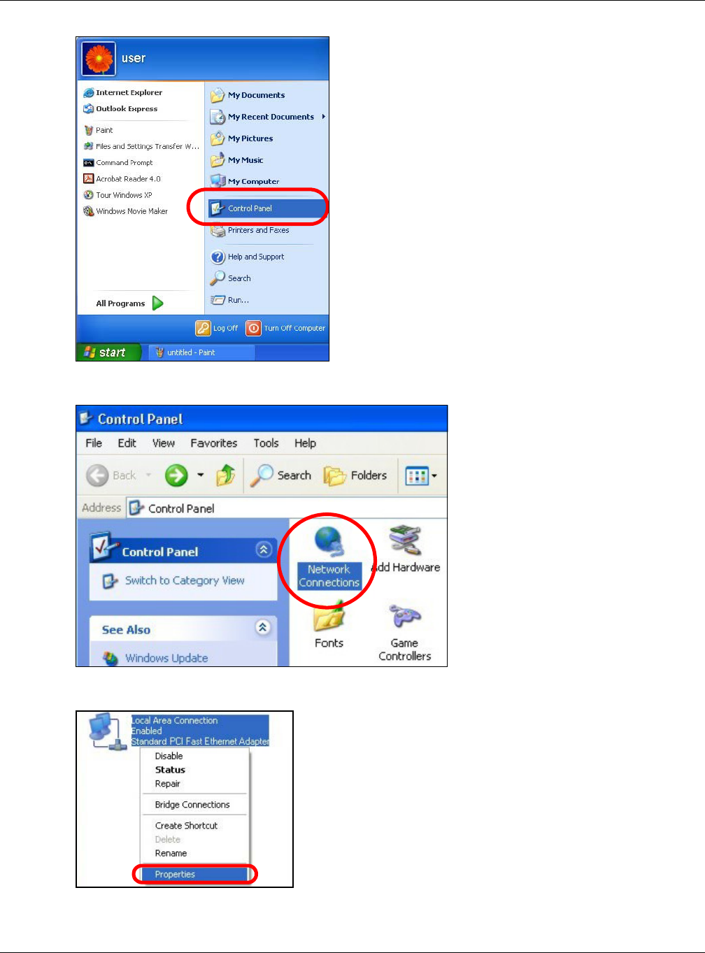
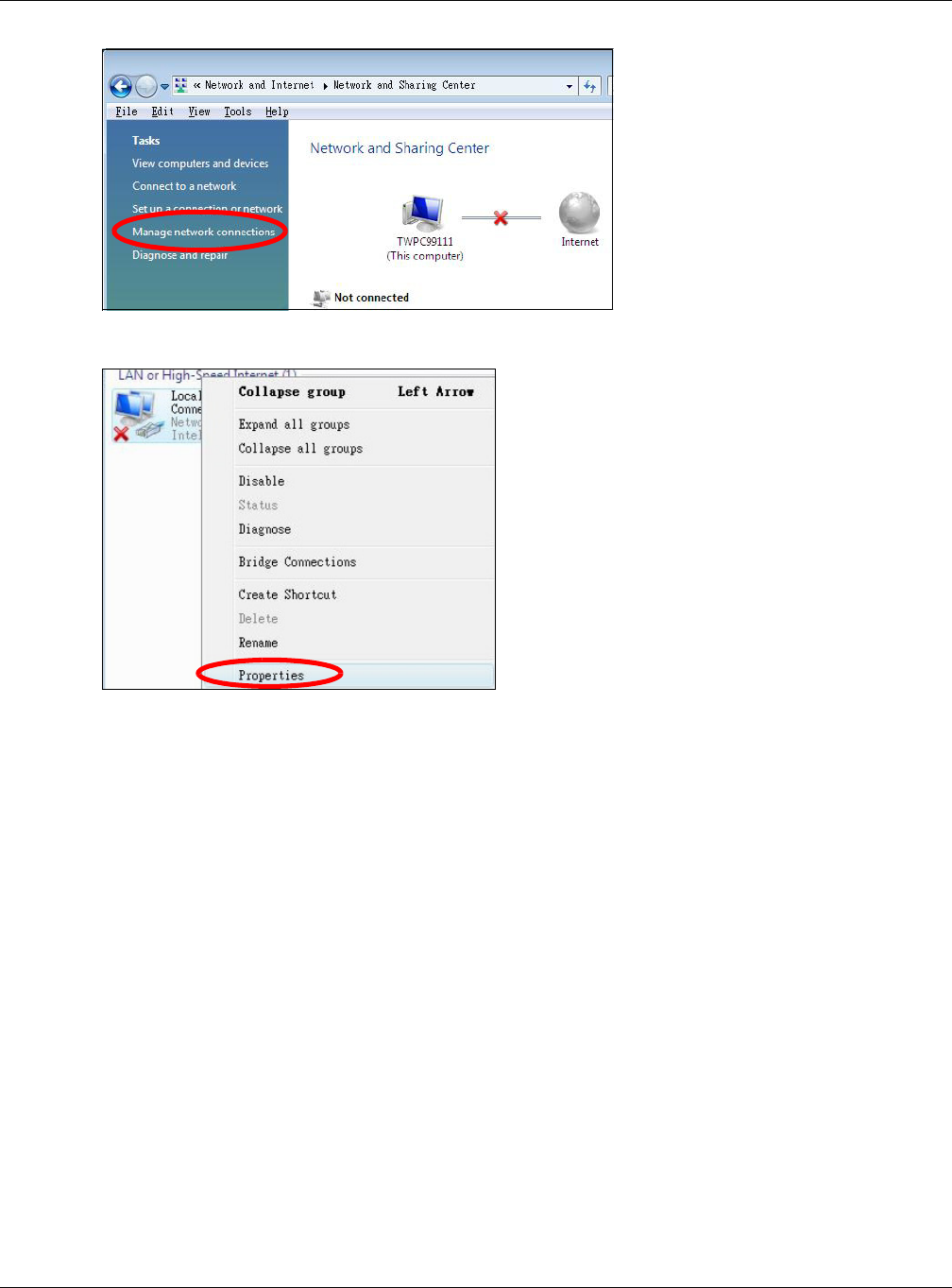
1Click St a rt > Cont r ol Pa n el.
Appendix C Setting Up Your Computer’s IP Address
NBG6515 User’s Guide
192
2In the Cont r ol Pan el, click the N et w ork Con ne ct ions icon.
3Right-click Loca l Area Conne ct ion and then select Pr ope r t ie s.
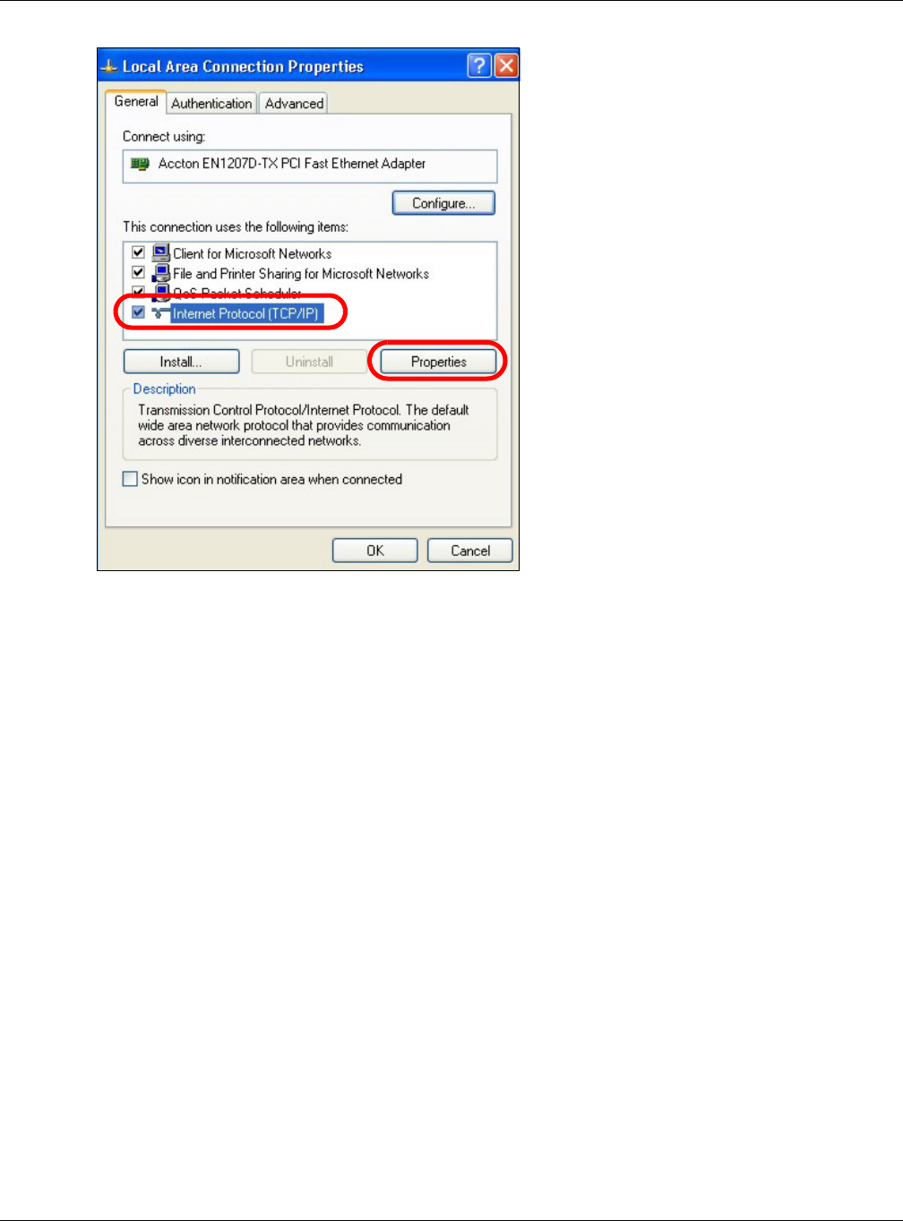
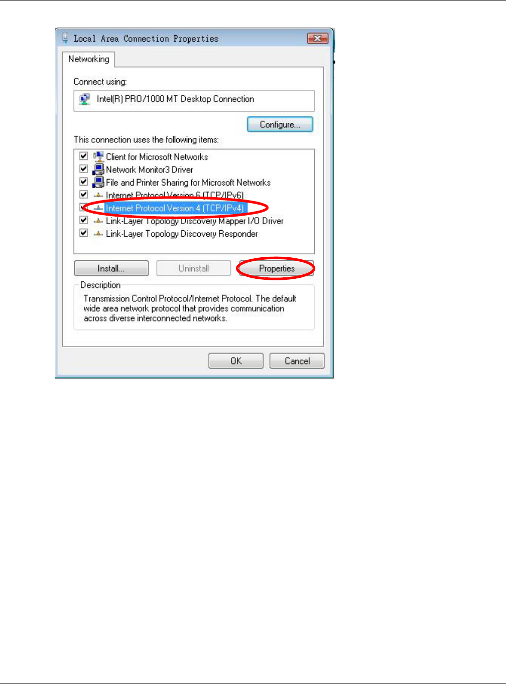
4On the Gen e ra l tab, select I nt er n et Prot ocol ( TCP/ I P) and then click Pr ope r t ie s.
Appendix C Setting Up Your Computer’s IP Address
NBG6515 User’s Guide
193
5The I nt e rne t Pr ot ocol TCP/ I P Prope rt ies window opens.
Appendix C Setting Up Your Computer’s IP Address
NBG6515 User’s Guide
194
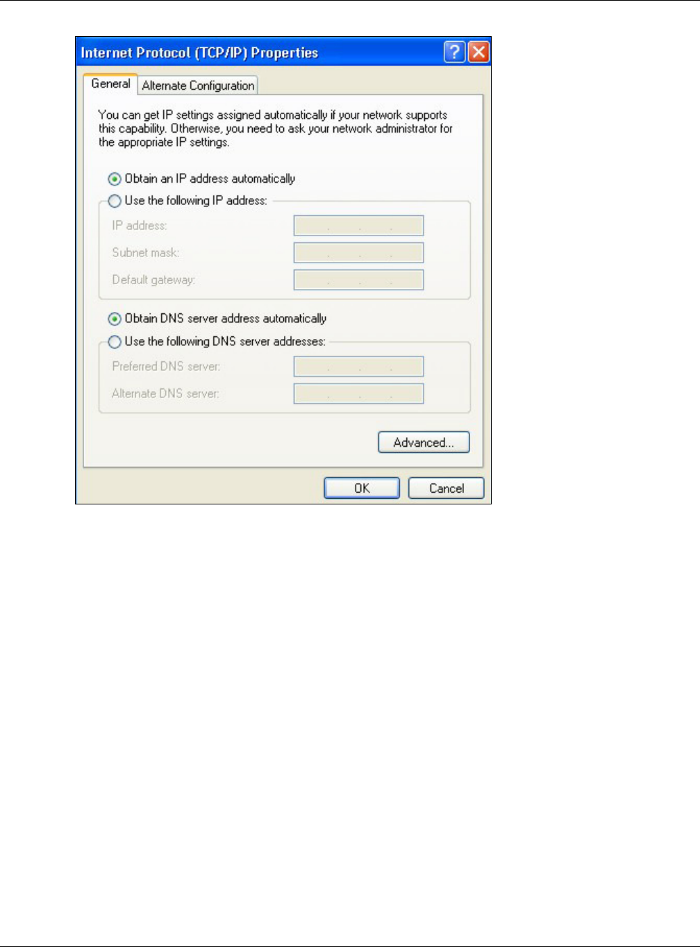
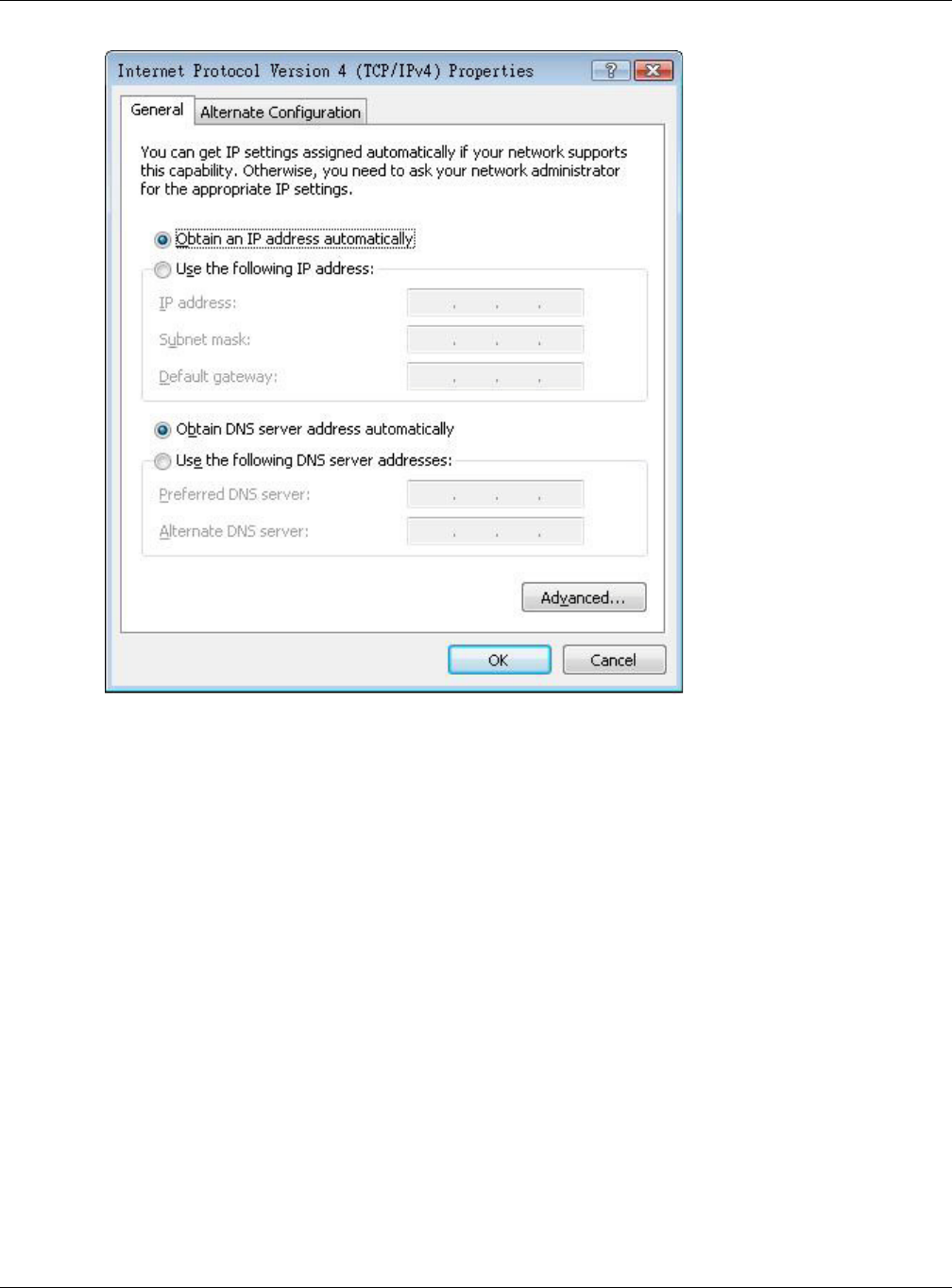
6Select Obt ain a n I P addre ss aut om at ica lly if your network administrator or ISP assigns your IP
address dynamically.
Select Use t h e follow ing I P Addre ss and fill in the I P a ddre ss, Subne t m ask, and D e fau lt
ga t e w a y fields if you have a static IP address that was assigned to you by your network
administrator or ISP. You may also have to enter a Pre fe r r e d D N S se rve r and an Alt e rn a t e DN S
ser ver , if that information was provided.
7Click OK to close the I nt erne t Prot ocol ( TCP/ I P) Proper t ie s window.
8Click OK to close the Loca l Area Conn ect ion Pr oper t ies window.
Verifying Settings
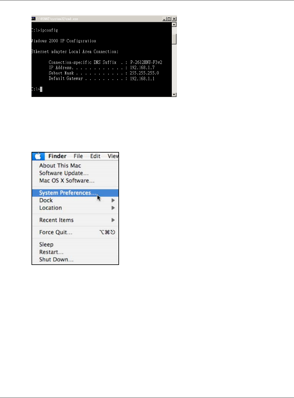
1Click St a rt > All Pr ogra m s > Acce ssor ies > Com m a nd Pr om pt .
2In the Com m a nd Pr om pt window, type "ipconfig" and then press [ENTER].
You can also go to St ar t > Cont r ol Pa n el > N e t w ork Conne ct ions, right-click a network
connection, click St a t u s and then click the Suppor t tab to view your IP address and connection
information.
Appendix C Setting Up Your Computer’s IP Address
NBG6515 User’s Guide
195
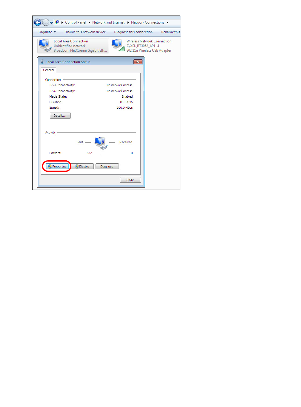
Windows Vista
This section shows screens from Windows Vista Professional.
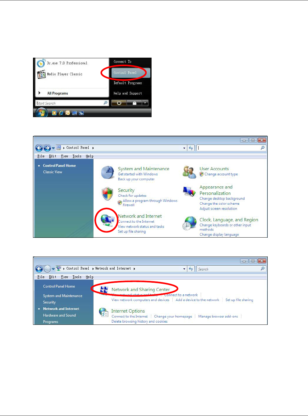
1Click St a rt > Cont rol Pa nel.
2In the Cont r ol Pan el, click the N et w ork a n d I nt er net icon.
3Click the N et w or k a nd Sha ring Ce n t e r icon.
4Click M ana ge ne t w or k connect ions.
Appendix C Setting Up Your Computer’s IP Address
NBG6515 User’s Guide
196
5Right-click Loca l Area Conne ct ion and then select Pr ope r t ie s.
Note: During this procedure, click Cont inue whenever Windows displays a screen saying
that it needs your permission to continue.
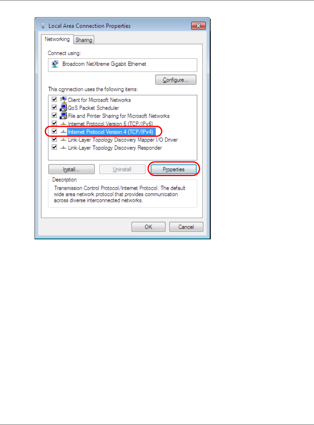
6Select I nt ern et Prot ocol Ve rsion 4 ( TCP/ I Pv4 ) and then select Pr op er t ie s.
Appendix C Setting Up Your Computer’s IP Address
NBG6515 User’s Guide
197
7The I nt e rne t Pr ot ocol Ver sion 4 ( TCP/ I Pv4 ) Prope rt ies window opens.
Appendix C Setting Up Your Computer’s IP Address
NBG6515 User’s Guide
198
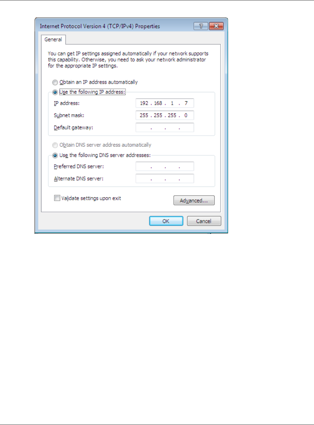
8Select Obt ain a n I P addre ss aut om at ica lly if your network administrator or ISP assigns your IP
address dynamically.
Select Use t h e follow ing I P Addre ss and fill in the I P a ddre ss, Subne t m ask, and D e fau lt
ga t e w a y fields if you have a static IP address that was assigned to you by your network
administrator or ISP. You may also have to enter a Pre fe r r e d D N S se rve r and an Alt e rn a t e DN S
ser ver , if that information was provided.Click Adva nce d .
9Click OK to close the I nt erne t Prot ocol ( TCP/ I P) Proper t ie s window.
10 Click OK to close the Loca l Area Conn ect ion Pr oper t ies window.
Verifying Settings
1Click St a rt > All Pr ogra m s > Acce ssor ies > Com m a nd Pr om pt .
2In the Com m a nd Pr om pt window, type "ipconfig" and then press [ENTER].
You can also go to St ar t > Cont r ol Pa n el > N e t w ork Conne ct ions, right-click a network
connection, click St a t u s and then click the Suppor t tab to view your IP address and connection
information.
Appendix C Setting Up Your Computer’s IP Address
NBG6515 User’s Guide
199
Windows 7
This section shows screens from Windows 7 Enterprise.
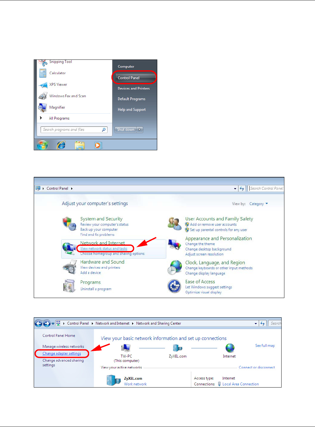
1Click St a rt > Cont rol Pa nel.
2In the Cont r ol Pan el, click View ne t w or k st at us a nd t ask s under the N e t w ork an d I nt e r n et
category.
3Click Cha nge a da pt e r se t t ings.
4Double click Local Ar ea Con nect ion and then select Pr op er t ie s.
Appendix C Setting Up Your Computer’s IP Address
NBG6515 User’s Guide
200
Note: During this procedure, click Cont inue whenever Windows displays a screen saying
that it needs your permission to continue.
5Select I nt ern et Prot ocol Ve rsion 4 ( TCP/ I Pv4 ) and then select Pr op er t ie s.
Appendix C Setting Up Your Computer’s IP Address
NBG6515 User’s Guide
201
6The I nt e rne t Pr ot ocol Ver sion 4 ( TCP/ I Pv4 ) Prope rt ies window opens.
Appendix C Setting Up Your Computer’s IP Address
NBG6515 User’s Guide
202
7Select Obt ain a n I P addre ss aut om at ica lly if your network administrator or ISP assigns your IP
address dynamically.
Select Use t h e follow ing I P Addre ss and fill in the I P a ddre ss, Subne t m ask, and D e fau lt
ga t e w a y fields if you have a static IP address that was assigned to you by your network
administrator or ISP. You may also have to enter a Pre fe r r e d D N S se rve r and an Alt e rn a t e DN S
ser ver , if that information was provided. Click Adva nced if you want to configure advanced
settings for IP, DNS and WINS.
8Click OK to close the I nt erne t Prot ocol ( TCP/ I P) Proper t ie s window.
9Click OK to close the Loca l Area Conn ect ion Pr oper t ies window.
Verifying Settings
1Click St a rt > All Pr ogra m s > Acce ssor ies > Com m a nd Pr om pt .
2In the Com m a nd Pr om pt window, type "ipconfig" and then press [ENTER].
3The IP settings are displayed as follows.
Appendix C Setting Up Your Computer’s IP Address
NBG6515 User’s Guide
203
Mac OS X: 10.3 and 10.4
The screens in this section are from Mac OS X 10.4 but can also apply to 10.3.
1Click Apple > Syste m Prefer e nces.
2In the Syst e m Prefere nces window, click the Net w or k icon.
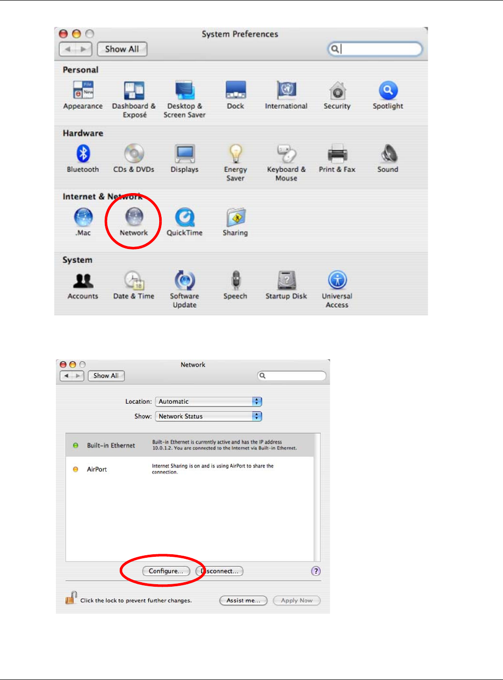
Appendix C Setting Up Your Computer’s IP Address
NBG6515 User’s Guide
204
3When the N e t w o rk preferences pane opens, select Built - in Et h e rne t from the network
connection type list, and then click Configure.
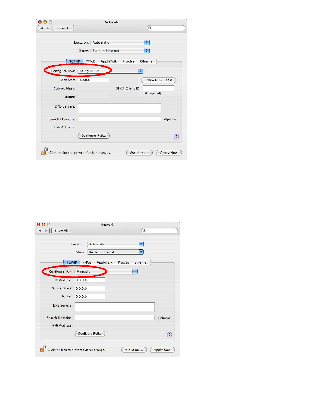
4For dynamically assigned settings, select Usin g D H CP from the Configur e I Pv4 list in the TCP/ I P
tab.
Appendix C Setting Up Your Computer’s IP Address
NBG6515 User’s Guide
205
5For statically assigned settings, do the following:
•From the Configu re I Pv4 list, select M anu a lly.
•In the I P Addre ss field, type your IP address.
•In the Subne t M ask field, type your subnet mask.
•In the Rou t e r field, type the IP address of your device.
6Click Apply N ow and close the window.
Verifying Settings
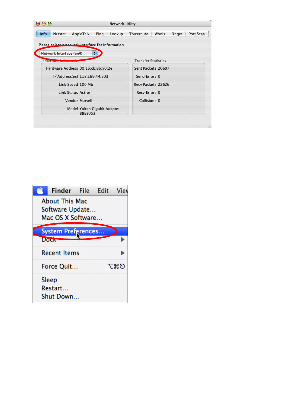
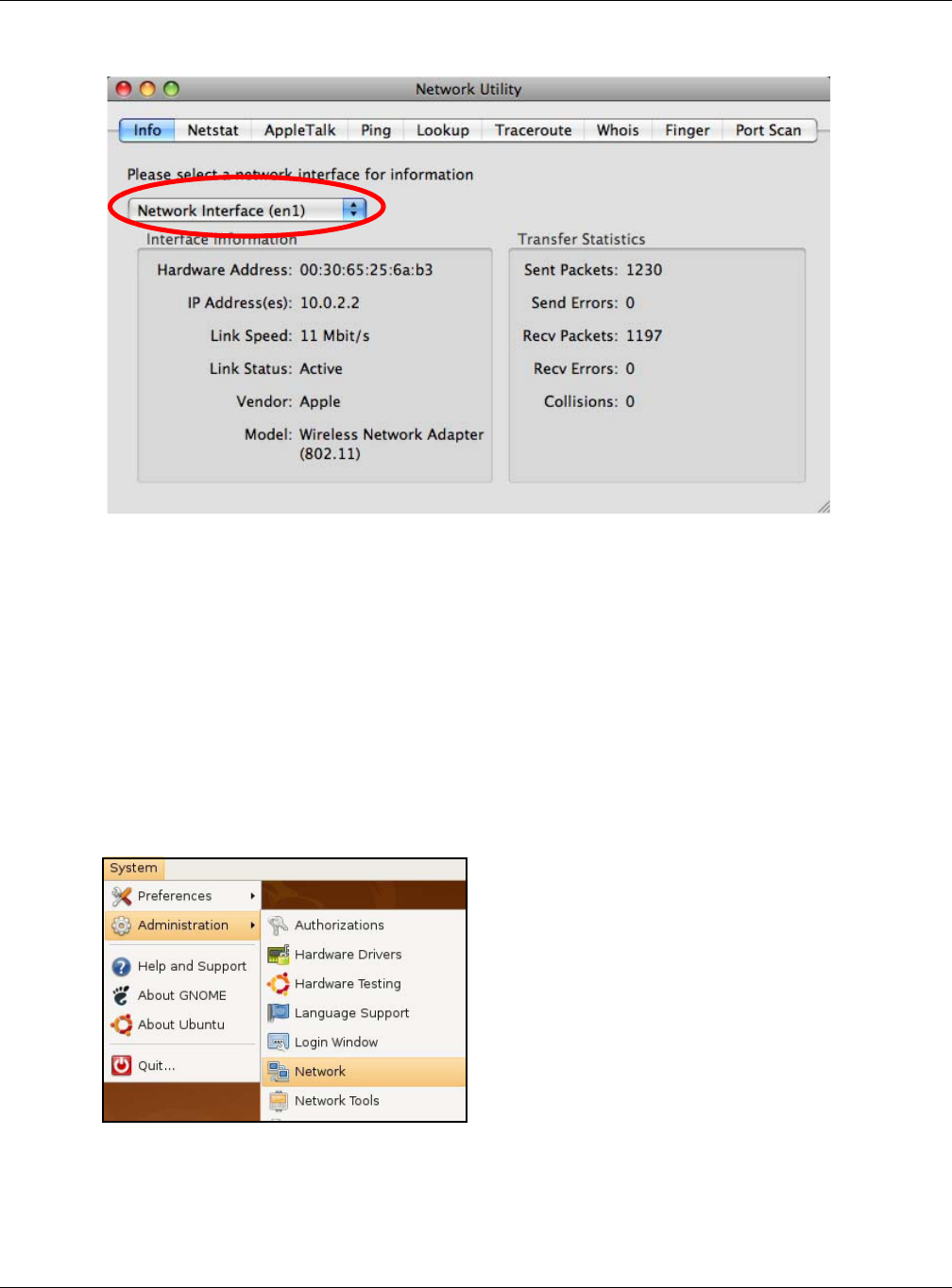
Check your TCP/IP properties by clicking Applicat ions > Ut ilit ie s > N e t w or k Ut ilit ie s, and then
selecting the appropriate N et w or k I nt er face from the I nfo tab.
Appendix C Setting Up Your Computer’s IP Address
NBG6515 User’s Guide
206
Figure 136 Mac OS X 10.4: Network Utility
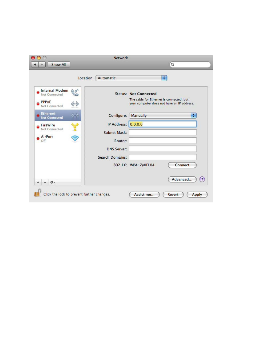
Mac OS X: 10.5 and 10.6
The screens in this section are from Mac OS X 10.5 but can also apply to 10.6.
1Click Apple > Syste m Prefer e nces.
2In Syst e m Pr e fer en ces, click the N e t w or k icon.
Appendix C Setting Up Your Computer’s IP Address
NBG6515 User’s Guide
207
3When the N et w ork preferences pane opens, select Et h e rn e t from the list of available connection
types.
4From the Configu r e list, select Using DH CP for dynamically assigned settings.
Appendix C Setting Up Your Computer’s IP Address
NBG6515 User’s Guide
208
5For statically assigned settings, do the following:
•From the Configu re list, select M a nua lly.
•In the I P Addre ss field, enter your IP address.
•In the Subne t M ask field, enter your subnet mask.
•In the Rou t e r field, enter the IP address of your NBG.
6Click Apply and close the window.
Verifying Settings
Check your TCP/IP properties by clicking Applicat ions > Ut ilit ie s > N e t w or k Ut ilit ie s, and then
selecting the appropriate N et w or k in te rfa ce from the I nfo tab.
Appendix C Setting Up Your Computer’s IP Address
NBG6515 User’s Guide
209
Figure 137 Mac OS X 10.5: Network Utility
Linux: Ubuntu 8 (GNOME)
This section shows you how to configure your computer’s TCP/IP settings in the GNU Object Model
Environment (GNOME) using the Ubuntu 8 Linux distribution. The procedure, screens and file
locations may vary depending on your specific distribution, release version, and individual
configuration. The following screens use the default Ubuntu 8 installation.
Note: Make sure you are logged in as the root administrator.
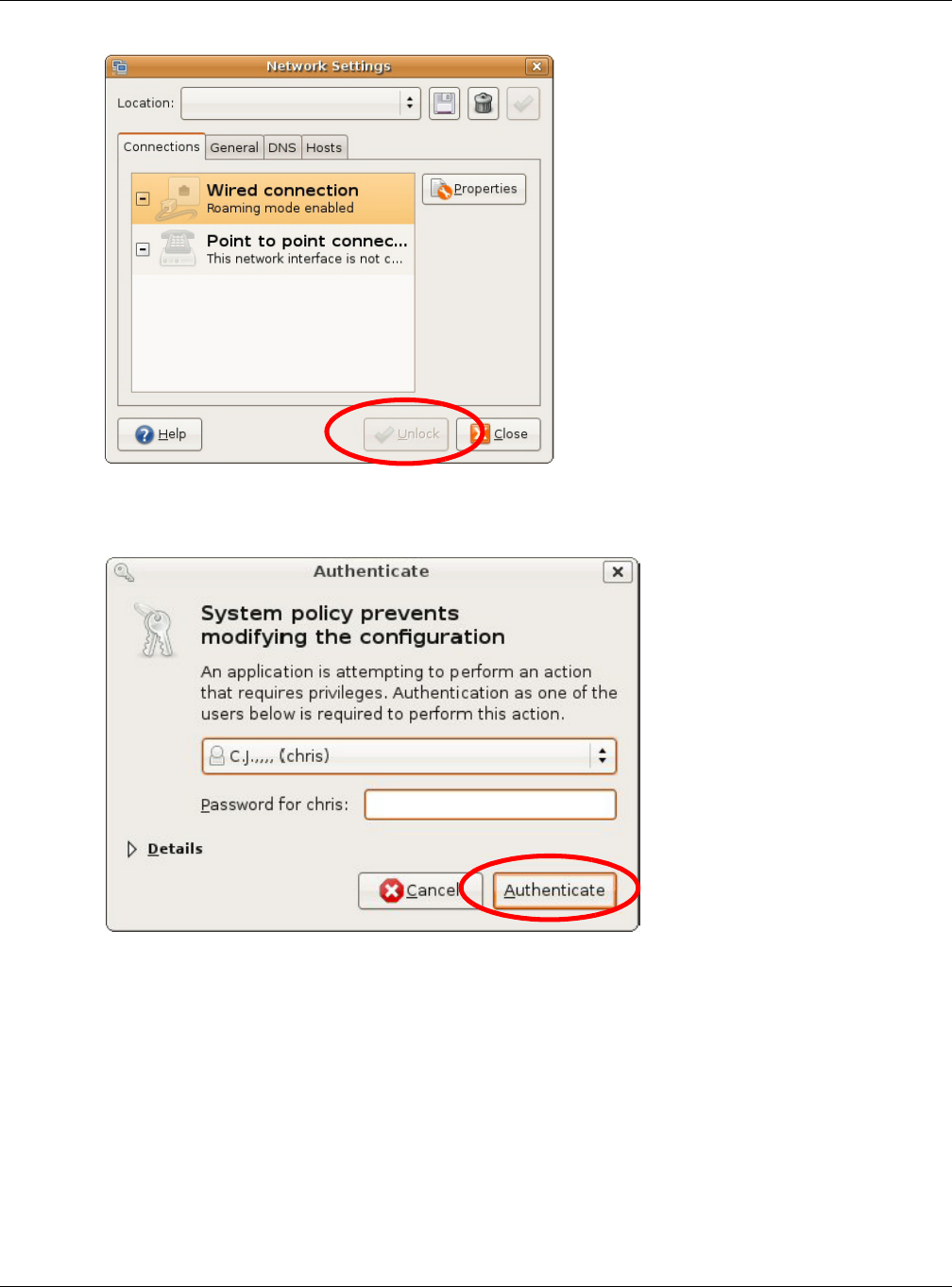
Follow the steps below to configure your computer IP address in GNOME:
1Click Syste m > Adm in ist r at ion > N et w ork .
2When the N et w ork Se t t ings window opens, click U nlo ck to open the Au t h en t ica t e window. (By
default, the Unlock button is greyed out until clicked.) You cannot make changes to your
configuration unless you first enter your admin password.
Appendix C Setting Up Your Computer’s IP Address
NBG6515 User’s Guide
210
3In the Au t he n t ica t e window, enter your admin account name and password then click the
Au t h en t ica t e button.
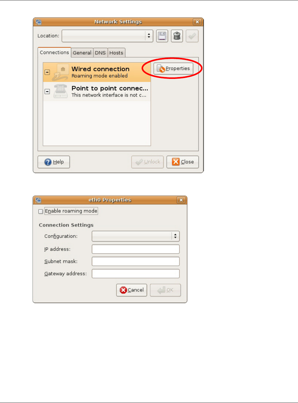
4In the N et w or k Set t ings window, select the connection that you want to configure, then click
Pr ope r t ie s.
Appendix C Setting Up Your Computer’s IP Address
NBG6515 User’s Guide
211
5The Pr ope r t ie s dialog box opens.
•In the Configu r at ion list, select Aut om at ic Configur at ion ( DH CP) if you have a dynamic IP
address.
•In the Con figur at ion list, select Sta t ic I P addr ess if you have a static IP address. Fill in the
I P a ddre ss, Subnet m a sk , and Ga t ew a y addre ss fields.
6Click OK to save the changes and close the Pr op er t ie s dialog box and return to the N et w ork
Se t t in gs screen.
7If you know your DNS server IP address(es), click the D N S tab in the N et w or k Set t in gs window
and then enter the DNS server information in the fields provided.
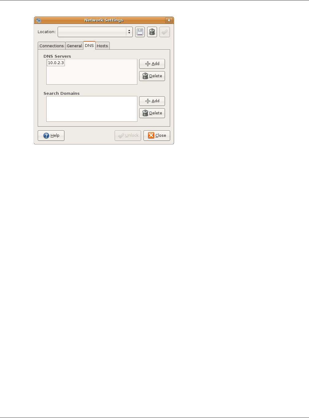
Appendix C Setting Up Your Computer’s IP Address
NBG6515 User’s Guide
212
8Click the Close button to apply the changes.
Verifying Settings
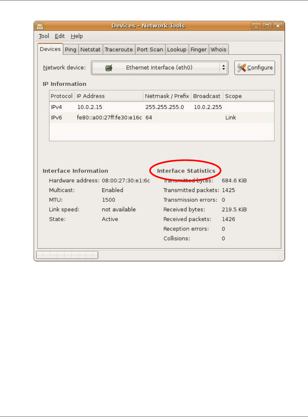
Check your TCP/IP properties by clicking Syst e m > Adm inist r at ion > N et w ork Tools, and then
selecting the appropriate N et w or k device from the De vice s tab. The I nt e r fa ce St a t ist ics
column shows data if your connection is working properly.
Appendix C Setting Up Your Computer’s IP Address
NBG6515 User’s Guide
213
Figure 138 Ubuntu 8: Network Tools
Linux: openSUSE 10.3 (KDE)
This section shows you how to configure your computer’s TCP/IP settings in the K Desktop
Environment (KDE) using the openSUSE 10.3 Linux distribution. The procedure, screens and file
locations may vary depending on your specific distribution, release version, and individual
configuration. The following screens use the default openSUSE 10.3 installation.
Note: Make sure you are logged in as the root administrator.
Follow the steps below to configure your computer IP address in the KDE:
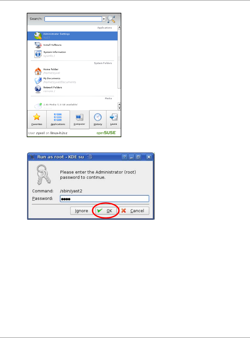
1Click K Me n u > Com put er > Adm in ist ra t or Set t ings ( YaST) .
Appendix C Setting Up Your Computer’s IP Address
NBG6515 User’s Guide
214
2When the Run as Root - KDE su dialog opens, enter the admin password and click OK.
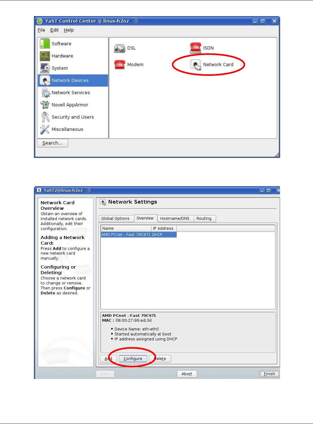
3When the Ya ST Cont rol Cent e r window opens, select N et w ork De vices and then click the
N et w ork Ca r d icon.
Appendix C Setting Up Your Computer’s IP Address
NBG6515 User’s Guide
215
4When the N et w ork Se t t ings window opens, click the Ove rvie w tab, select the appropriate
connection N a m e from the list, and then click the Configure button.
5When the N et w ork Ca r d Se t u p window opens, click the Addre ss tab
Appendix C Setting Up Your Computer’s IP Address
NBG6515 User’s Guide
216
Figure 139 openSUSE 10.3: Network Card Setup
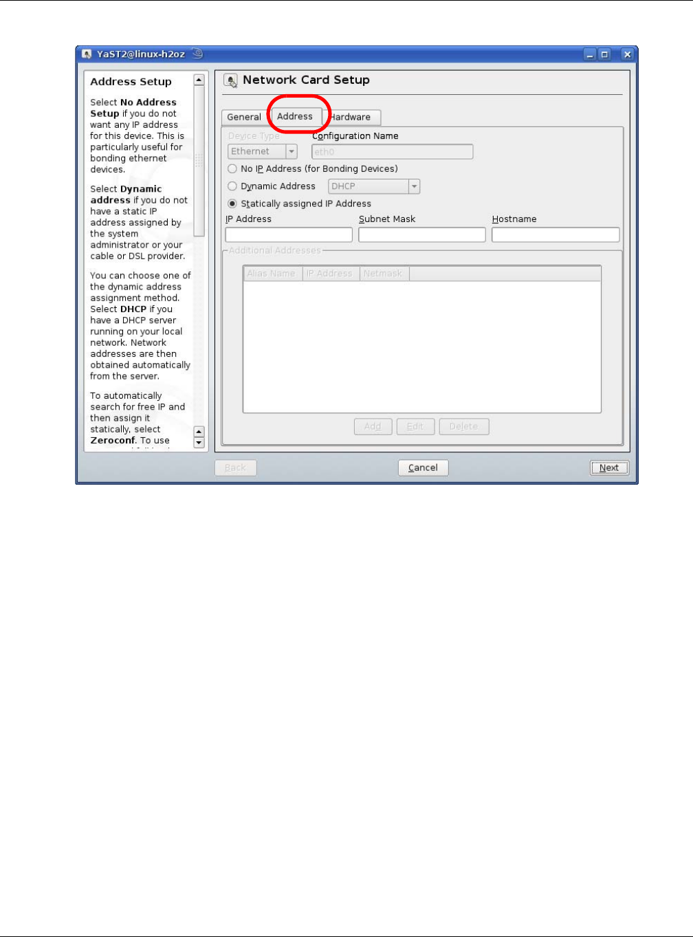
6Select Dyna m ic Addre ss ( D HCP) if you have a dynamic IP address.
Select St a t ically a ssigne d I P Addr e ss if you have a static IP address. Fill in the I P a ddr ess,
Subne t m ask , and H ost na m e fields.
7Click N e x t to save the changes and close the N e t w ork Ca rd Set up window.
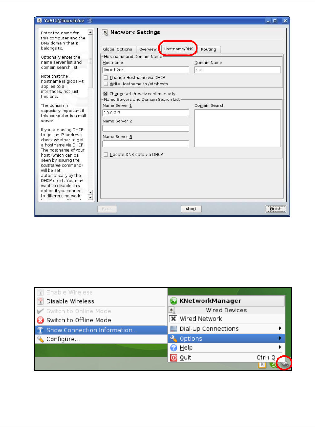
8If you know your DNS server IP address(es), click the H ost n am e / D N S tab in N et w or k Set t ings
and then enter the DNS server information in the fields provided.
Appendix C Setting Up Your Computer’s IP Address
NBG6515 User’s Guide
217
9Click Finish to save your settings and close the window.
Verifying Settings
Click the KNe t w or k M ana ger icon on the Ta sk bar to check your TCP/IP properties. From the
Opt ion s sub-menu, select Sh ow Connect ion I nfor m a t ion.
Figure 140 openSUSE 10.3: KNetwork Manager
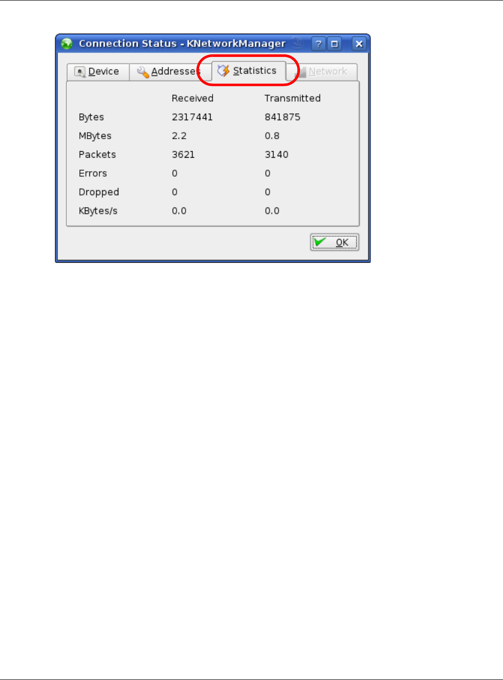
When the Conne ct ion St a t us - KN e t w or k M a n ager window opens, click the St a t ist ics t a b to
see if your connection is working properly.
Appendix C Setting Up Your Computer’s IP Address
NBG6515 User’s Guide
218
Figure 141 openSUSE: Connection Status - KNetwork Manager
NBG6515 User’s Guide
219
APPENDIX D
Wireless LANs
Wireless LAN Topologies
This section discusses ad-hoc and infrastructure wireless LAN topologies.
Ad-hoc Wireless LAN Configuration
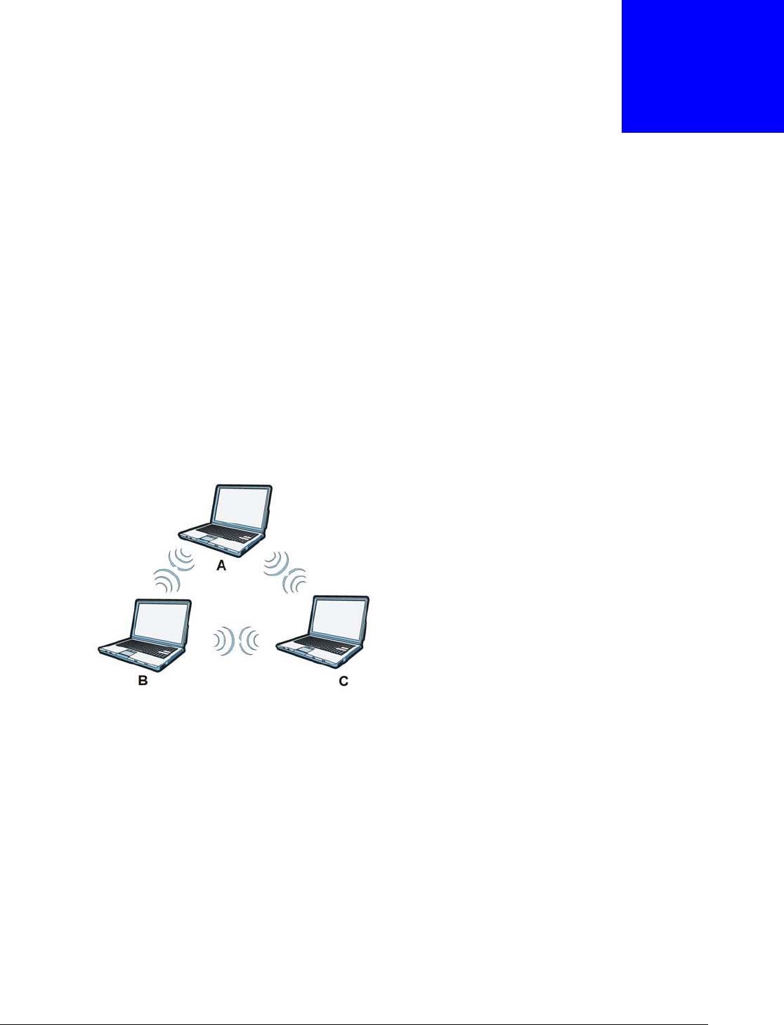
The simplest WLAN configuration is an independent (Ad-hoc) WLAN that connects a set of
computers with wireless adapters (A, B, C). Any time two or more wireless adapters are within
range of each other, they can set up an independent network, which is commonly referred to as an
ad-hoc network or Independent Basic Service Set (IBSS). The following diagram shows an example
of notebook computers using wireless adapters to form an ad-hoc wireless LAN.
Figure 142 Peer-to-Peer Communication in an Ad-hoc Network
BSS
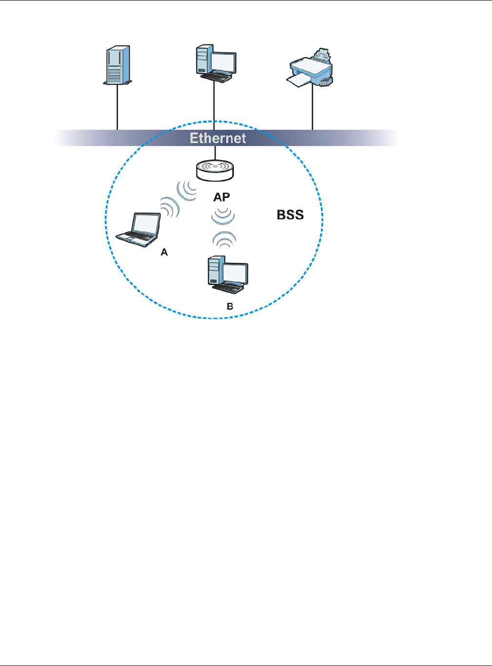
A Basic Service Set (BSS) exists when all communications between wireless clients or between a
wireless client and a wired network client go through one access point (AP).
Intra-BSS traffic is traffic between wireless clients in the BSS. When Intra-BSS is enabled, wireless
client A and B can access the wired network and communicate with each other. When Intra-BSS is
disabled, wireless client A and B can still access the wired network but cannot communicate with
each other.
Appendix D Wireless LANs
NBG6515 User’s Guide
220
Figure 143 Basic Service Set
ESS
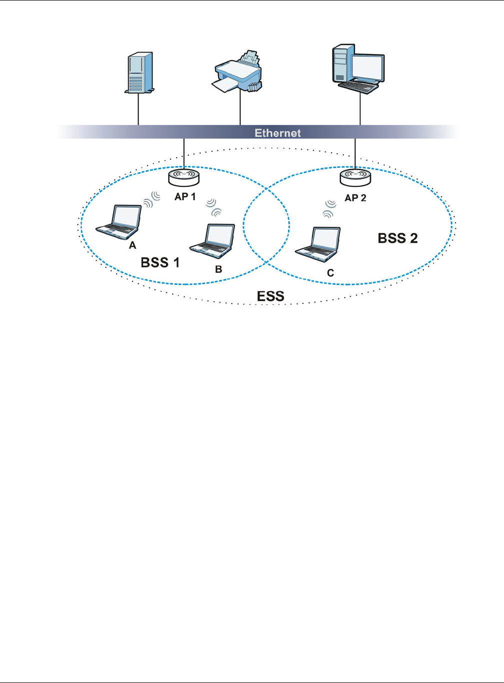
An Extended Service Set (ESS) consists of a series of overlapping BSSs, each containing an access
point, with each access point connected together by a wired network. This wired connection
between APs is called a Distribution System (DS).
This type of wireless LAN topology is called an Infrastructure WLAN. The Access Points not only
provide communication with the wired network but also mediate wireless network traffic in the
immediate neighborhood.
An ESSID (ESS IDentification) uniquely identifies each ESS. All access points and their associated
wireless clients within the same ESS must have the same ESSID in order to communicate.
Appendix D Wireless LANs
NBG6515 User’s Guide
221
Figure 144 Infrastructure WLAN
Channel
A channel is the radio frequency(ies) used by wireless devices to transmit and receive data.
Channels available depend on your geographical area. You may have a choice of channels (for your
region) so you should use a channel different from an adjacent AP (access point) to reduce
interference. Interference occurs when radio signals from different access points overlap causing
interference and degrading performance.
Adjacent channels partially overlap however. To avoid interference due to overlap, your AP should
be on a channel at least five channels away from a channel that an adjacent AP is using. For
example, if your region has 11 channels and an adjacent AP is using channel 1, then you need to
select a channel between 6 or 11.
RTS/CTS
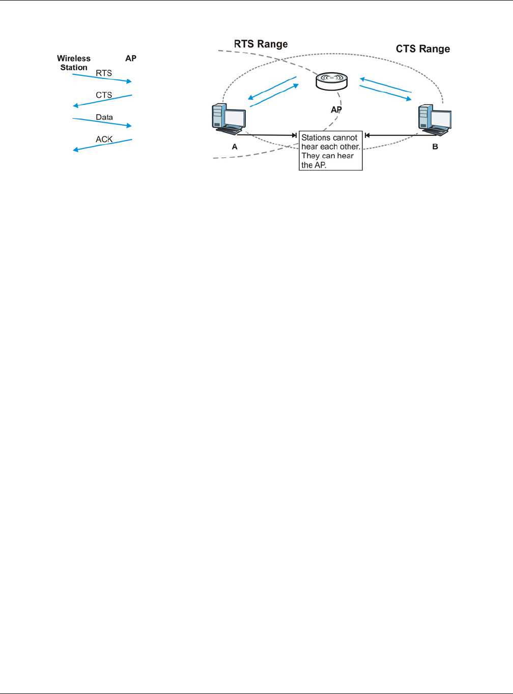
A hidden node occurs when two stations are within range of the same access point, but are not
within range of each other. The following figure illustrates a hidden node. Both stations (STA) are
within range of the access point (AP) or wireless gateway, but out-of-range of each other, so they
cannot "hear" each other, that is they do not know if the channel is currently being used. Therefore,
they are considered hidden from each other.
Appendix D Wireless LANs
NBG6515 User’s Guide
222
Figure 145 RTS/CTS
When station A sends data to the AP, it might not know that the station B is already using the
channel. If these two stations send data at the same time, collisions may occur when both sets of
data arrive at the AP at the same time, resulting in a loss of messages for both stations.
RTS/ CTS is designed to prevent collisions due to hidden nodes. An RTS/ CTS defines the biggest
size data frame you can send before an RTS (Request To Send)/CTS (Clear to Send) handshake is
invoked.
When a data frame exceeds the RTS/ CTS value you set, the station that wants to transmit this
frame must first send an RTS (Request To Send) message to the AP for permission to send it. The
AP then responds with a CTS (Clear to Send) message to all other stations within its range to notify
them to defer their transmission. It also reserves and confirms with the requesting station the time
frame for the requested transmission.
Stations can send frames smaller than the specified RTS/ CTS directly to the AP without the RTS
(Request To Send)/CTS (Clear to Send) handshake.
You should only configure RTS/ CTS if the possibility of hidden nodes exists on your network and
the "cost" of resending large frames is more than the extra network overhead involved in the RTS
(Request To Send)/CTS (Clear to Send) handshake.
If the RTS/ CTS value is greater than the Fr agm en t a t ion Thre shold value (see next), then the
RTS (Request To Send)/CTS (Clear to Send) handshake will never occur as data frames will be
fragmented before they reach RTS/ CTS size.
Note: Enabling the RTS Threshold causes redundant network overhead that could
negatively affect the throughput performance instead of providing a remedy.
Fragmentation Threshold
A Fr a gm ent a t ion Th resh old is the maximum data fragment size that can be sent in the wireless
network before the AP will fragment the packet into smaller data frames.
A large Fra gm ent a t ion Thr esh old is recommended for networks not prone to interference while
you should set a smaller threshold for busy networks or networks that are prone to interference.
If the Fr agm en t at ion Thre shold value is smaller than the RTS/ CTS value (see previously) you
set then the RTS (Request To Send)/CTS (Clear to Send) handshake will never occur as data frames
will be fragmented before they reach RTS/ CTS size.

Appendix D Wireless LANs
NBG6515 User’s Guide
223
Preamble Type
Preamble is used to signal that data is coming to the receiver. Short and long refer to the length of
the synchronization field in a packet.
Short preamble increases performance as less time sending preamble means more time for sending
data. All IEEE 802.11 compliant wireless adapters support long preamble, but not all support short
preamble.
Use long preamble if you are unsure what preamble mode other wireless devices on the network
support, and to provide more reliable communications in busy wireless networks.
Use short preamble if you are sure all wireless devices on the network support it, and to provide
more efficient communications.
Use the dynamic setting to automatically use short preamble when all wireless devices on the
network support it, otherwise the NBG uses long preamble.
Note: The wireless devices MUST use the same preamble mode in order to communicate.
Wireless Security Overview
Wireless security is vital to your network to protect wireless communication between wireless
clients, access points and the wired network.
Wireless security methods available on the NBG are data encryption, wireless client authentication,
restricting access by device MAC address and hiding the NBG identity.
The following figure shows the relative effectiveness of these wireless security methods available on
your NBG.
Note: You must enable the same wireless security settings on the NBG and on all wireless
clients that you want to associate with it.
Table 92 Wireless Security Levels
SECURITY
LEVEL SECURITY TYPE
Least
Secure
Most Secure
Unique SSID (Default)
Unique SSID with Hide SSID Enabled
MAC Address Filtering
WEP Encryption
IEEE802.1x EAP with RADIUS Server Authentication
Wi-Fi Protected Access (WPA)
WPA2

Appendix D Wireless LANs
NBG6515 User’s Guide
224
IEEE 802.1x
In June 2001, the IEEE 802.1x standard was designed to extend the features of IEEE 802.11 to
support extended authentication as well as providing additional accounting and control features. It
is supported by Windows XP and a number of network devices. Some advantages of IEEE 802.1x
are:
• User based identification that allows for roaming.
• Support for RADIUS (Remote Authentication Dial In User Service, RFC 2138, 2139) for
centralized user profile and accounting management on a network RADIUS server.
• Support for EAP (Extensible Authentication Protocol, RFC 2486) that allows additional
authentication methods to be deployed with no changes to the access point or the wireless
clients.
RADIUS
RADIUS is based on a client-server model that supports authentication, authorization and
accounting. The access point is the client and the server is the RADIUS server. The RADIUS server
handles the following tasks:
• Authentication
Determines the identity of the users.
•Authorization
Determines the network services available to authenticated users once they are connected to the
network.
• Accounting
Keeps track of the client’s network activity.
RADIUS is a simple package exchange in which your AP acts as a message relay between the
wireless client and the network RADIUS server.
Types of RADIUS Messages
The following types of RADIUS messages are exchanged between the access point and the RADIUS
server for user authentication:
• Access-Request
Sent by an access point requesting authentication.
• Access-Reject
Sent by a RADIUS server rejecting access.
• Access-Accept
Sent by a RADIUS server allowing access.
• Access-Challenge
Sent by a RADIUS server requesting more information in order to allow access. The access point
sends a proper response from the user and then sends another Access-Request message.
The following types of RADIUS messages are exchanged between the access point and the RADIUS
server for user accounting:

Appendix D Wireless LANs
NBG6515 User’s Guide
225
• Accounting-Request
Sent by the access point requesting accounting.
• Accounting-Response
Sent by the RADIUS server to indicate that it has started or stopped accounting.
In order to ensure network security, the access point and the RADIUS server use a shared secret
key, which is a password, they both know. The key is not sent over the network. In addition to the
shared key, password information exchanged is also encrypted to protect the network from
unauthorized access.
Types of EAP Authentication
This section discusses some popular authentication types: EAP-MD5, EAP-TLS, EAP-TTLS, PEAP and
LEAP. Your wireless LAN device may not support all authentication types.
EAP (Extensible Authentication Protocol) is an authentication protocol that runs on top of the IEEE
802.1x transport mechanism in order to support multiple types of user authentication. By using EAP
to interact with an EAP-compatible RADIUS server, an access point helps a wireless station and a
RADIUS server perform authentication.
The type of authentication you use depends on the RADIUS server and an intermediary AP(s) that
supports IEEE 802.1x. .
For EAP-TLS authentication type, you must first have a wired connection to the network and obtain
the certificate(s) from a certificate authority (CA). A certificate (also called digital IDs) can be used
to authenticate users and a CA issues certificates and guarantees the identity of each certificate
owner.
EAP-MD5 (Message-Digest Algorithm 5)
MD5 authentication is the simplest one-way authentication method. The authentication server
sends a challenge to the wireless client. The wireless client ‘proves’ that it knows the password by
encrypting the password with the challenge and sends back the information. Password is not sent in
plain text.
However, MD5 authentication has some weaknesses. Since the authentication server needs to get
the plaintext passwords, the passwords must be stored. Thus someone other than the
authentication server may access the password file. In addition, it is possible to impersonate an
authentication server as MD5 authentication method does not perform mutual authentication.
Finally, MD5 authentication method does not support data encryption with dynamic session key. You
must configure WEP encryption keys for data encryption.
EAP-TLS (Transport Layer Security)
With EAP-TLS, digital certifications are needed by both the server and the wireless clients for
mutual authentication. The server presents a certificate to the client. After validating the identity of
the server, the client sends a different certificate to the server. The exchange of certificates is done
in the open before a secured tunnel is created. This makes user identity vulnerable to passive
attacks. A digital certificate is an electronic ID card that authenticates the sender’s identity.
However, to implement EAP-TLS, you need a Certificate Authority (CA) to handle certificates, which
imposes a management overhead.

Appendix D Wireless LANs
NBG6515 User’s Guide
226
EAP-TTLS (Tunneled Transport Layer Service)
EAP-TTLS is an extension of the EAP-TLS authentication that uses certificates for only the server-
side authentications to establish a secure connection. Client authentication is then done by sending
username and password through the secure connection, thus client identity is protected. For client
authentication, EAP-TTLS supports EAP methods and legacy authentication methods such as PAP,
CHAP, MS-CHAP and MS-CHAP v2.
PEAP (Protected EAP)
Like EAP-TTLS, server-side certificate authentication is used to establish a secure connection, then
use simple username and password methods through the secured connection to authenticate the
clients, thus hiding client identity. However, PEAP only supports EAP methods, such as EAP-MD5,
EAP-MSCHAPv2 and EAP-GTC (EAP-Generic Token Card), for client authentication. EAP-GTC is
implemented only by Cisco.
LEAP
LEAP (Lightweight Extensible Authentication Protocol) is a Cisco implementation of IEEE 802.1x.
Dynamic WEP Key Exchange
The AP maps a unique key that is generated with the RADIUS server. This key expires when the
wireless connection times out, disconnects or reauthentication times out. A new WEP key is
generated each time reauthentication is performed.
If this feature is enabled, it is not necessary to configure a default encryption key in the wireless
security configuration screen. You may still configure and store keys, but they will not be used while
dynamic WEP is enabled.
Note: EAP-MD5 cannot be used with Dynamic WEP Key Exchange
For added security, certificate-based authentications (EAP-TLS, EAP-TTLS and PEAP) use dynamic
keys for data encryption. They are often deployed in corporate environments, but for public
deployment, a simple user name and password pair is more practical. The following table is a
comparison of the features of authentication types.
Table 93 Comparison of EAP Authentication Types
EAP-MD5 EAP-TLS EAP-TTLS PEAP LEAP
Mutual Authentication No Yes Yes Yes Yes
Certificate – Client No Yes Optional Optional No
Certificate – Server No Yes Yes Yes No
Dynamic Key Exchange No Yes Yes Yes Yes
Credential Integrity None Strong Strong Strong Moderate
Deployment Difficulty Easy Hard Moderate Moderate Moderate
Client Identity Protection No No Yes Yes No

Appendix D Wireless LANs
NBG6515 User’s Guide
227
WPA and WPA2
Wi-Fi Protected Access (WPA) is a subset of the IEEE 802.11i standard. WPA2 (IEEE 802.11i) is a
wireless security standard that defines stronger encryption, authentication and key management
than WPA.
Key differences between WPA or WPA2 and WEP are improved data encryption and user
authentication.
If both an AP and the wireless clients support WPA2 and you have an external RADIUS server, use
WPA2 for stronger data encryption. If you don't have an external RADIUS server, you should use
WPA2-PSK (WPA2-Pre-Shared Key) that only requires a single (identical) password entered into
each access point, wireless gateway and wireless client. As long as the passwords match, a wireless
client will be granted access to a WLAN.
If the AP or the wireless clients do not support WPA2, just use WPA or WPA-PSK depending on
whether you have an external RADIUS server or not.
Select WEP only when the AP and/or wireless clients do not support WPA or WPA2. WEP is less
secure than WPA or WPA2.
Encryption
WPA improves data encryption by using Temporal Key Integrity Protocol (TKIP), Message Integrity
Check (MIC) and IEEE 802.1x. WPA2 also uses TKIP when required for compatibility reasons, but
offers stronger encryption than TKIP with Advanced Encryption Standard (AES) in the Counter
mode with Cipher block chaining Message authentication code Protocol (CCMP).
TKIP uses 128-bit keys that are dynamically generated and distributed by the authentication server.
AES (Advanced Encryption Standard) is a block cipher that uses a 256-bit mathematical algorithm
called Rijndael. They both include a per-packet key mixing function, a Message Integrity Check
(MIC) named Michael, an extended initialization vector (IV) with sequencing rules, and a re-keying
mechanism.
WPA and WPA2 regularly change and rotate the encryption keys so that the same encryption key is
never used twice.
The RADIUS server distributes a Pairwise Master Key (PMK) key to the AP that then sets up a key
hierarchy and management system, using the PMK to dynamically generate unique data encryption
keys to encrypt every data packet that is wirelessly communicated between the AP and the wireless
clients. This all happens in the background automatically.
The Message Integrity Check (MIC) is designed to prevent an attacker from capturing data packets,
altering them and resending them. The MIC provides a strong mathematical function in which the
receiver and the transmitter each compute and then compare the MIC. If they do not match, it is
assumed that the data has been tampered with and the packet is dropped.
By generating unique data encryption keys for every data packet and by creating an integrity
checking mechanism (MIC), with TKIP and AES it is more difficult to decrypt data on a Wi-Fi
network than WEP and difficult for an intruder to break into the network.
The encryption mechanisms used for WPA(2) and WPA(2)-PSK are the same. The only difference
between the two is that WPA(2)-PSK uses a simple common password, instead of user-specific
credentials. The common-password approach makes WPA(2)-PSK susceptible to brute-force

Appendix D Wireless LANs
NBG6515 User’s Guide
228
password-guessing attacks but it’s still an improvement over WEP as it employs a consistent,
single, alphanumeric password to derive a PMK which is used to generate unique temporal
encryption keys. This prevent all wireless devices sharing the same encryption keys. (a weakness of
WEP)
User Authentication
WPA and WPA2 apply IEEE 802.1x and Extensible Authentication Protocol (EAP) to authenticate
wireless clients using an external RADIUS database. WPA2 reduces the number of key exchange
messages from six to four (CCMP 4-way handshake) and shortens the time required to connect to a
network. Other WPA2 authentication features that are different from WPA include key caching and
pre-authentication. These two features are optional and may not be supported in all wireless
devices.
Key caching allows a wireless client to store the PMK it derived through a successful authentication
with an AP. The wireless client uses the PMK when it tries to connect to the same AP and does not
need to go with the authentication process again.
Pre-authentication enables fast roaming by allowing the wireless client (already connecting to an
AP) to perform IEEE 802.1x authentication with another AP before connecting to it.
Wireless Client WPA Supplicants
A wireless client supplicant is the software that runs on an operating system instructing the wireless
client how to use WPA. At the time of writing, the most widely available supplicant is the WPA patch
for Windows XP, Funk Software's Odyssey client.
The Windows XP patch is a free download that adds WPA capability to Windows XP's built-in "Zero
Configuration" wireless client. However, you must run Windows XP to use it.
WPA(2) with RADIUS Application Example
To set up WPA(2), you need the IP address of the RADIUS server, its port number (default is 1812),
and the RADIUS shared secret. A WPA(2) application example with an external RADIUS server
looks as follows. "A" is the RADIUS server. "DS" is the distribution system.
1The AP passes the wireless client's authentication request to the RADIUS server.
2The RADIUS server then checks the user's identification against its database and grants or denies
network access accordingly.
3A 256-bit Pairwise Master Key (PMK) is derived from the authentication process by the RADIUS
server and the client.
4The RADIUS server distributes the PMK to the AP. The AP then sets up a key hierarchy and
management system, using the PMK to dynamically generate unique data encryption keys. The
keys are used to encrypt every data packet that is wirelessly communicated between the AP and
the wireless clients.
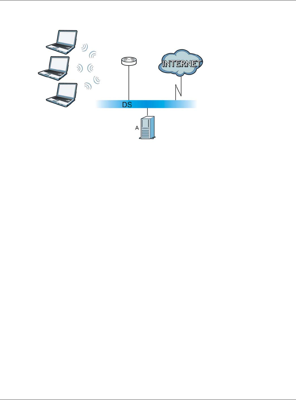
Appendix D Wireless LANs
NBG6515 User’s Guide
229
Figure 146 WPA(2) with RADIUS Application Example
WPA(2)-PSK Application Example
A WPA(2)-PSK application looks as follows.
1First enter identical passwords into the AP and all wireless clients. The Pre-Shared Key (PSK) must
consist of between 8 and 63 ASCII characters or 64 hexadecimal characters (including spaces and
symbols).
2The AP checks each wireless client's password and allows it to join the network only if the password
matches.
3The AP and wireless clients generate a common PMK (Pairwise Master Key). The key itself is not
sent over the network, but is derived from the PSK and the SSID.
4The AP and wireless clients use the TKIP or AES encryption process, the PMK and information
exchanged in a handshake to create temporal encryption keys. They use these keys to encrypt data
exchanged between them.
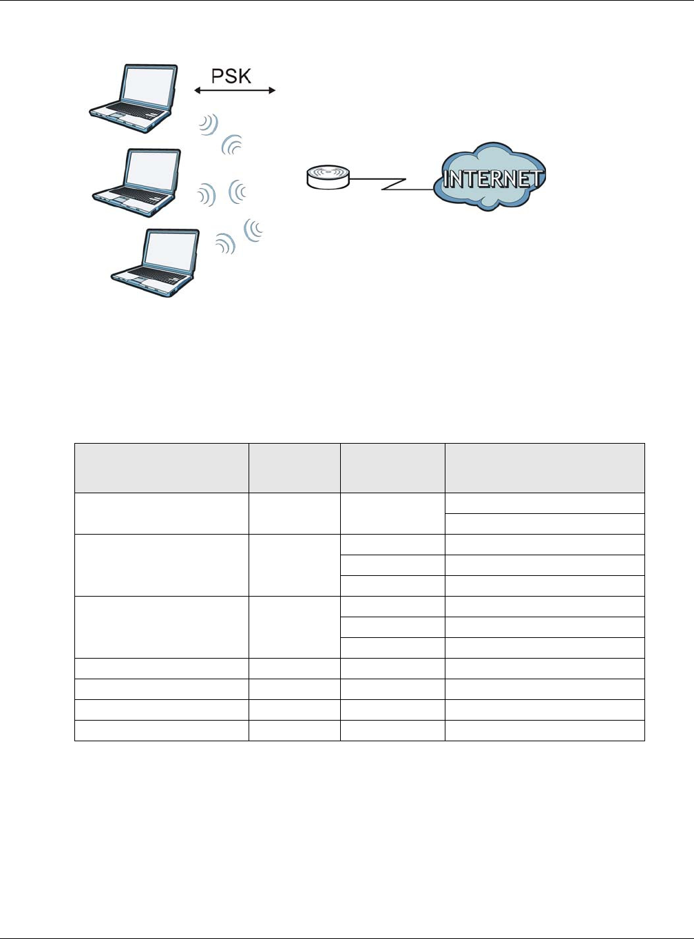
Appendix D Wireless LANs
NBG6515 User’s Guide
230
Figure 147 WPA(2)-PSK Authentication
Security Parameters Summary
Refer to this table to see what other security parameters you should configure for each
authentication method or key management protocol type. MAC address filters are not dependent on
how you configure these security features.
Antenna Overview
An antenna couples RF signals onto air. A transmitter within a wireless device sends an RF signal to
the antenna, which propagates the signal through the air. The antenna also operates in reverse by
capturing RF signals from the air.
Positioning the antennas properly increases the range and coverage area of a wireless LAN.
Table 94 Wireless Security Relational Matrix
AUTHENTICATION
METHOD/ KEY
MANAGEMENT PROTOCOL
ENCRYPTIO
N METHOD
ENTER
MANUAL KEY IEEE 802.1X
Open None No Disable
Enable without Dynamic WEP Key
Open WEP No Enable with Dynamic WEP Key
Yes Enable without Dynamic WEP Key
Yes Disable
Shared WEP No Enable with Dynamic WEP Key
Yes Enable without Dynamic WEP Key
Yes Disable
WPA TKIP/AES No Enable
WPA-PSK TKIP/AES Yes Disable
WPA2 TKIP/AES No Enable
WPA2-PSK TKIP/AES Yes Disable

Appendix D Wireless LANs
NBG6515 User’s Guide
231
Antenna Characteristics
Frequency
An antenna in the frequency of 2.4GHz or 5GHz is needed to communicate efficiently in a wireless
LAN
Radiation Pattern
A radiation pattern is a diagram that allows you to visualize the shape of the antenna’s coverage
area.
Antenna Gain
Antenna gain, measured in dB (decibel), is the increase in coverage within the RF beam width.
Higher antenna gain improves the range of the signal for better communications.
For an indoor site, each 1 dB increase in antenna gain results in a range increase of approximately
2.5%. For an unobstructed outdoor site, each 1dB increase in gain results in a range increase of
approximately 5%. Actual results may vary depending on the network environment.
Antenna gain is sometimes specified in dBi, which is how much the antenna increases the signal
power compared to using an isotropic antenna. An isotropic antenna is a theoretical perfect antenna
that sends out radio signals equally well in all directions. dBi represents the true gain that the
antenna provides.
Types of Antennas for WLAN
There are two types of antennas used for wireless LAN applications.
• Omni-directional antennas send the RF signal out in all directions on a horizontal plane. The
coverage area is torus-shaped (like a donut) which makes these antennas ideal for a room
environment. With a wide coverage area, it is possible to make circular overlapping coverage
areas with multiple access points.
• Directional antennas concentrate the RF signal in a beam, like a flashlight does with the light
from its bulb. The angle of the beam determines the width of the coverage pattern. Angles
typically range from 20 degrees (very directional) to 120 degrees (less directional). Directional
antennas are ideal for hallways and outdoor point-to-point applications.
Positioning Antennas
In general, antennas should be mounted as high as practically possible and free of obstructions. In
point-to–point application, position both antennas at the same height and in a direct line of sight to
each other to attain the best performance.
For omni-directional antennas mounted on a table, desk, and so on, point the antenna up. For
omni-directional antennas mounted on a wall or ceiling, point the antenna down. For a single AP
application, place omni-directional antennas as close to the center of the coverage area as possible.
For directional antennas, point the antenna in the direction of the desired coverage area.

NBG6515 User’s Guide
232
APPENDIX E
Common Services
The following table lists some commonly-used services and their associated protocols and port
numbers. For a comprehensive list of port numbers, ICMP type/code numbers and services, visit
the IANA (Internet Assigned Number Authority) web site.
•N a m e : This is a short, descriptive name for the service. You can use this one or create a
different one, if you like.
•Pr ot ocol: This is the type of IP protocol used by the service. If this is TCP/ UDP, then the service
uses the same port number with TCP and UDP. If this is USER- D EFI N ED , the Po rt ( s) is the IP
protocol number, not the port number.
•Por t ( s) : This value depends on the Pr ot o col. Please refer to RFC 1700 for further information
about port numbers.
•If the Pr ot oco l is TCP, UD P, or TCP/ UD P, this is the IP port number.
•If the Pr ot oco l is USER, this is the IP protocol number.
•D e scr ip t ion : This is a brief explanation of the applications that use this service or the situations
in which this service is used.
Table 95 Commonly Used Services
NAME PROTOCOL PORT(S) DESCRIPTION
AH
(IPSEC_TUNNEL)
User-Defined 51 The IPSEC AH (Authentication Header)
tunneling protocol uses this service.
AIM/New-ICQ TCP 5190 AOL’s Internet Messenger service. It is
also used as a listening port by ICQ.
AUTH TCP 113 Authentication protocol used by some
servers.
BGP TCP 179 Border Gateway Protocol.
BOOTP_CLIENT UDP 68 DHCP Client.
BOOTP_SERVER UDP 67 DHCP Server.
CU-SEEME TCP
UDP
7648
24032
A popular videoconferencing solution from
White Pines Software.
DNS TCP/UDP 53 Domain Name Server, a service that
matches web names (for example
www.zyxel.com) to IP numbers.
ESP
(IPSEC_TUNNEL)
User-Defined 50 The IPSEC ESP (Encapsulation Security
Protocol) tunneling protocol uses this
service.
FINGER TCP 79 Finger is a UNIX or Internet related
command that can be used to find out if a
user is logged on.
FTP TCP
TCP
20
21
File Transfer Program, a program to enable
fast transfer of files, including large files
that may not be possible by e-mail.
H.323 TCP 1720 NetMeeting uses this protocol.

Appendix E Common Services
NBG6515 User’s Guide
233
HTTP TCP 80 Hyper Text Transfer Protocol - a client/
server protocol for the world wide web.
HTTPS TCP 443 HTTPS is a secured http session often used
in e-commerce.
ICMP User-Defined 1Internet Control Message Protocol is often
used for diagnostic or routing purposes.
ICQ UDP 4000 This is a popular Internet chat program.
IGMP (MULTICAST) User-Defined 2Internet Group Management Protocol is
used when sending packets to a specific
group of hosts.
IKE UDP 500 The Internet Key Exchange algorithm is
used for key distribution and
management.
IRC TCP/UDP 6667 This is another popular Internet chat
program.
MSN Messenger TCP 1863 Microsoft Networks’ messenger service
uses this protocol.
NEW-ICQ TCP 5190 An Internet chat program.
NEWS TCP 144 A protocol for news groups.
NFS UDP 2049 Network File System - NFS is a client/
server distributed file service that provides
transparent file sharing for network
environments.
NNTP TCP 119 Network News Transport Protocol is the
delivery mechanism for the USENET
newsgroup service.
PING User-Defined 1Packet INternet Groper is a protocol that
sends out ICMP echo requests to test
whether or not a remote host is reachable.
POP3 TCP 110 Post Office Protocol version 3 lets a client
computer get e-mail from a POP3 server
through a temporary connection (TCP/IP
or other).
PPTP TCP 1723 Point-to-Point Tunneling Protocol enables
secure transfer of data over public
networks. This is the control channel.
PPTP_TUNNEL
(GRE)
User-Defined 47 PPTP (Point-to-Point Tunneling Protocol)
enables secure transfer of data over public
networks. This is the data channel.
RCMD TCP 512 Remote Command Service.
REAL_AUDIO TCP 7070 A streaming audio service that enables
real time sound over the web.
REXEC TCP 514 Remote Execution Daemon.
RLOGIN TCP 513 Remote Login.
RTELNET TCP 107 Remote Telnet.
RTSP TCP/UDP 554 The Real Time Streaming (media control)
Protocol (RTSP) is a remote control for
multimedia on the Internet.
SFTP TCP 115 Simple File Transfer Protocol.
Table 95 Commonly Used Services (continued)
NAME PROTOCOL PORT(S) DESCRIPTION

Appendix E Common Services
NBG6515 User’s Guide
234
SMTP TCP 25 Simple Mail Transfer Protocol is the
message-exchange standard for the
Internet. SMTP enables you to move
messages from one e-mail server to
another.
SNMP TCP/UDP 161 Simple Network Management Program.
SNMP-TRAPS TCP/UDP 162 Traps for use with the SNMP (RFC:1215).
SQL-NET TCP 1521 Structured Query Language is an interface
to access data on many different types of
database systems, including mainframes,
midrange systems, UNIX systems and
network servers.
SSH TCP/UDP 22 Secure Shell Remote Login Program.
STRM WORKS UDP 1558 Stream Works Protocol.
SYSLOG UDP 514 Syslog allows you to send system logs to a
UNIX server.
TACACS UDP 49 Login Host Protocol used for (Terminal
Access Controller Access Control System).
TELNET TCP 23 Telnet is the login and terminal emulation
protocol common on the Internet and in
UNIX environments. It operates over TCP/
IP networks. Its primary function is to
allow users to log into remote host
systems.
TFTP UDP 69 Trivial File Transfer Protocol is an Internet
file transfer protocol similar to FTP, but
uses the UDP (User Datagram Protocol)
rather than TCP (Transmission Control
Protocol).
VDOLIVE TCP 7000 Another videoconferencing solution.
Table 95 Commonly Used Services (continued)
NAME PROTOCOL PORT(S) DESCRIPTION

Index
NBG6515 User’s Guide
235
Index
A
Address Assignment 102
Advanced Encryption Standard
See AES.
AES 227
alternative subnet mask notation 176
antenna
directional 231
gain 231
omni-directional 231
AP 12
AP (access point) 221
AP Mode
menu 60, 67
status screen 58
AP+Bridge 12
B
Bandwidth management
overview 136
priority 138
Basic Service Set, See BSS 219
Bridge/Repeater 12
bridged APs, security 83
BSS 219
C
CA 225
Certificate Authority
See CA.
certifications
viewing 190
Channel 52, 59, 60, 66
channel 81, 221
interference 221
CIFS 153
Common Internet File System, see CIFS
Configuration
restore 165
content filtering 134
by keyword (in URL) 134
by web feature 134
copyright 184
CPU usage 53, 60, 66
CTS (Clear to Send) 222
D
Daylight saving 163
DDNS 123
see also Dynamic DNS
service providers 123
DHCP 32, 114
DHCP server
see also Dynamic Host Configuration Protocol
DHCP server 112, 114
DHCP table 32
DHCP client information
DHCP status
DHCP Unique IDentifier 98
DHCPv6
DHCP Unique IDentifier 98
Digital Living Network Alliance 152
disclaimer 184
DLNA 151, 152
indexing 155
overview 151
rescan 155
DLNA-compliant client 152
DNS 116
DNS Server 102
DNS server 116
documentation
related 2

Index
NBG6515 User’s Guide
236
Domain Name System 116
Domain Name System. See DNS.
DUID 98
duplex setting 53, 60
Dynamic DNS 123
Dynamic Host Configuration Protocol 114
dynamic WEP key exchange 226
DynDNS 123
DynDNS see also DDNS 123
E
EAP Authentication 225
encryption 82, 227
key 82
WPA compatible 82
ESS 220
ESSID 171
Extended Service Set, See ESS 220
F
FCC interference statement 184
file sharing 152
access right 155, 156
example 156
FTP 155
overview 152
Samba 154
user account 154, 156
Windows Explorer 154
work group 154
Firewall
ICMP packets 129, 130
Firmware upload 163
file extension
using HTTP
firmware version 52, 59
fragmentation threshold 222
G
General wireless LAN screen 83, 85
Guide
Quick Start 2
H
hidden node 221
I
IANA 181
IBSS 219
IGMP 103
see also Internet Group Multicast Protocol
version
IGMP version 103
Independent Basic Service Set
See IBSS 219
initialization vector (IV) 227
interfaces 96
Internet Assigned Numbers Authority
See IANA 181
Internet Group Multicast Protocol 103
Internet Protocol version 6, see IPv6
IP Address 113, 118, 119
IP alias 112
IP Pool 114
IPv6 96
link-local address 97
prefix 96
prefix delegation 97
prefix length 96
stateless autoconfiguration 97
L
LAN 111
IP pool setup 112
LAN overview 111

Index
NBG6515 User’s Guide
237
LAN setup 111
LAN TCP/IP 112
Language 166
Link type 53, 60, 66
Local Area Network 111
M
MAC 89
MAC address 81, 102
cloning 102
MAC address filter 81
MAC address filtering 89
MAC filter 89
managing the device
good habits 13
using the web configurator. See web configurator.
using the wireless switch.
using the WPS. See WPS.
MBSSID 12
Media access control 89
media client 151
media file 151
media server 151
overview 151
meida file play 151
Memory usage 53, 60, 66
Message Integrity Check (MIC) 227
mode 12
Multicast 103
IGMP 103
N
NAT 117, 118, 181
how it works 117
overview 117
see also Network Address Translation
NAT Traversal 144
Navigation Panel 53, 60, 67
navigation panel 53, 60, 67
Network Address Translation 117, 118
O
operating mode 12
other documentation 2
P
Pairwise Master Key (PMK) 227, 229
Point-to-Point Protocol over Ethernet 105
Point-to-Point Tunneling Protocol 107
Port forwarding 119
default server 118
local server 119
port speed 53, 60, 67
PPPoE 105
dial-up connection
PPTP 107
preamble mode 223
prefix delegation 97
product registration 190
PSK 227
Q
Quality of Service (QoS) 91
Quick Start Guide 2
R
RADIUS 224
message types 224
messages 224
shared secret key 225
registration
product 190
related documentation 2
Remote management
and NAT 142
limitations 142
system timeout 143
Reset button 30

Index
NBG6515 User’s Guide
238
Reset the device 30
Restore configuration 165
Roaming 90
RTS (Request To Send) 222
threshold 221, 222
RTS/CTS Threshold 81, 90
S
Samba 153
Scheduling 93
Server Message Block, see SMB
Service and port numbers 130, 133, 141
Service Set 47, 84
Service Set IDentification 47, 84
Service Set IDentity. See SSID.
SMB 153
SSID 47, 52, 59, 60, 66, 81, 84
Static DHCP 115
Static Route 125
Status 50
subnet 174
Subnet Mask 113
subnet mask 175
subnetting 177
Summary
DHCP table 32
Packet statistics 33
Wireless station status 34, 35
System General Setup 160
System restart 166
T
TCP/IP configuration 114
Temporal Key Integrity Protocol (TKIP) 227
Time setting 162
trademarks 184
trigger port 120
Trigger port forwarding 120
example 121
process 121
U
Universal 63
Universal Plug and Play 144
Application 144
Security issues 145
Universal Repeater 63, 67
UPnP 144
URL Keyword Blocking 135
USB media sharing 151
User Name 124
V
VPN 107
W
WAN (Wide Area Network) 101
WAN advanced 109
WAN MAC address 102
warranty 190
note 190
Web Configurator
how to access 26
Overview 26
web configurator 12
WEP Encryption 68, 70, 87, 88
WEP encryption 86
WEP key 86
Wi-Fi Protected Access 227
windows media player 151
Wireless association list 34, 35
wireless channel 171
wireless client WPA supplicants 228
wireless LAN 171
wireless LAN scheduling 93
Wireless network
basic guidelines 80
channel 81
encryption 82
example 80

Index
NBG6515 User’s Guide
239
MAC address filter 81
overview 80
security 81
SSID 81
Wireless security 81
overview 81
type 81
wireless security 171, 223
wireless switch 12
Wireless tutorial 72
WPS 72
Wizard setup 17
WLAN
interference 221
security parameters 230
WLAN 2.4G 34
WLAN 5G 35
work group 153
name 153
Windows 153
WPA 227
key caching 228
pre-authentication 228
user authentication 228
vs WPA-PSK 227
wireless client supplicant 228
with RADIUS application example 228
WPA compatible 82
WPA2 227
user authentication 228
vs WPA2-PSK 227
wireless client supplicant 228
with RADIUS application example 228
WPA2-Pre-Shared Key 227
WPA2-PSK 227
application example 229
WPA-PSK 227
application example 229
WPS 12