ZyXEL Communications NBG6515 AC750 Dual band Wireless Gigabit Router User Manual Book
ZyXEL Communications Corporation AC750 Dual band Wireless Gigabit Router Book
Contents
- 1. Users Manual
- 2. Users Manual 2
Users Manual
Quick Start Guide
www.zyxel.com
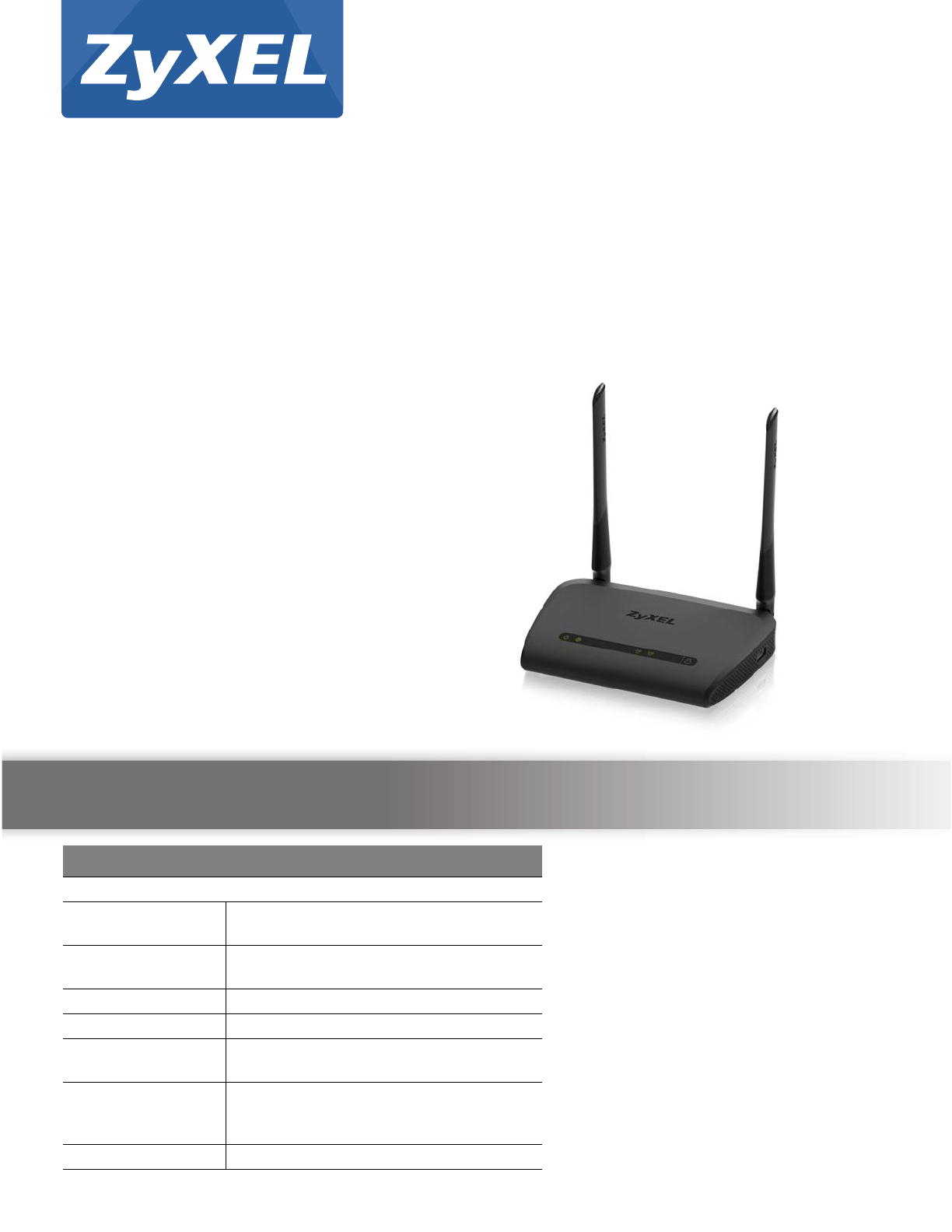
NBG6515
AC750 Dual-Band Wireless Gigabit Router
Version 1.00
Edition 1, 05/2015
User’s Guide
Default Details
LAN IP Address
- Router Mode
(Default mode) http://192.168.1.1
- AP/Repeater
Mode http://192.168.1.2
User Name admin
Password 1234
2.4G SSID ZyXEL + Last 6 digits of the 2.4G MAC
address (ZyXEL734916)
5G SSID ZyXEL+ Last 6 digits of the 5G MAC
address + .speed
(ZyXEL734917.speed)
Pre-shared Key Serial number + Random key
Copyright © 2015 ZyXEL Communications Corporation

NBG6515 User’s Guide
2
IMPORTANT!
READ CAREFULLY BEFORE USE.
KEEP THIS GUIDE FOR FUTURE REFERENCE.
Screenshots and graphics in this book may differ slightly from your product due to differences in
your product firmware or your computer operating system. Every effort has been made to ensure
that the information in this manual is accurate.
Related Documentation
•Quick Start Guide
The Quick Start Guide shows how to connect the NBG and access the Web Configurator.
Note: It is recommended you use the Web Configurator to configure the NBG.

Contents Overview
NBG6515 User’s Guide
3
Contents Overview
User’s Guide .......................................................................................................................................11
Getting to Know Your NBG .....................................................................................................................12
Connection Wizard ..................................................................................................................................17
Introducing the Web Configurator ...........................................................................................................26
Monitor ....................................................................................................................................................31
NBG Modes .............................................................................................................................................36
Easy Mode ..............................................................................................................................................38
Router Mode ...........................................................................................................................................50
Access Point Mode .................................................................................................................................57
Universal Repeater Mode .......................................................................................................................63
Tutorials ..................................................................................................................................................72
Technical Reference ..........................................................................................................................79
Wireless LAN ..........................................................................................................................................80
IPv6 .........................................................................................................................................................96
WAN ......................................................................................................................................................101
LAN ....................................................................................................................................................... 111
DHCP Server ........................................................................................................................................ 114
Network Address Translation (NAT) ...................................................................................................... 117
Dynamic DNS ........................................................................................................................................123
Static Route ...........................................................................................................................................125
Firewall ..................................................................................................................................................127
Content Filter .........................................................................................................................................134
Bandwidth Management .......................................................................................................................136
Remote Management ............................................................................................................................142
Universal Plug-and-Play (UPnP) ...........................................................................................................144
USB Media Sharing ...............................................................................................................................151
Maintenance ..........................................................................................................................................160
Troubleshooting ....................................................................................................................................167

Table of Contents
NBG6515 User’s Guide
4
Table of Contents
Contents Overview ..............................................................................................................................3
Table of Contents .................................................................................................................................4
Part I: User’s Guide ......................................................................................... 11
Chapter 1
Getting to Know Your NBG................................................................................................................12
1.1 Overview ...........................................................................................................................................12
1.2 Applications .......................................................................................................................................12
1.3 Ways to Manage the NBG ................................................................................................................12
1.4 Good Habits for Managing the NBG .................................................................................................13
1.5 LEDs .................................................................................................................................................14
1.6 The WPS Button ...............................................................................................................................15
1.7 Wall Mounting ...................................................................................................................................15
Chapter 2
Connection Wizard .............................................................................................................................17
2.1 Overview ...........................................................................................................................................17
2.2 Accessing the Wizard ........................................................................................................................17
2.3 Connect to Internet ............................................................................................................................17
2.3.1 Connection Type: DHCP .........................................................................................................18
2.3.2 Connection Type: Static IP ......................................................................................................19
2.3.3 Connection Type: PPPoE ........................................................................................................20
2.3.4 Connection Type: PPTP ..........................................................................................................21
2.4 Router Password ...............................................................................................................................22
2.5 Wireless Security ..............................................................................................................................23
2.5.1 Wireless Security: No Security ................................................................................................23
2.5.2 Wireless Security: WPA-PSK/WPA2-PSK ...............................................................................24
Chapter 3
Introducing the Web Configurator ....................................................................................................26
3.1 Overview ...........................................................................................................................................26
3.2 Accessing the Web Configurator .......................................................................................................26
3.2.1 Login Screen ...........................................................................................................................26
3.2.2 Password Screen ....................................................................................................................27
3.2.3 Home Screen ...........................................................................................................................28
3.3 Resetting the NBG ............................................................................................................................30

Table of Contents
NBG6515 User’s Guide
5
3.3.1 Procedure to Use the Reset Button .........................................................................................30
Chapter 4
Monitor.................................................................................................................................................31
4.1 Overview ...........................................................................................................................................31
4.2 What You Can Do .............................................................................................................................31
4.3 The Log Screen .................................................................................................................................31
4.3.1 View Log ..................................................................................................................................31
4.4 DHCP Table ...................................................................................................................................32
4.5 Packet Statistics ...............................................................................................................................33
4.6 WLAN 2.4G Station Status ............................................................................................................34
4.7 WLAN 5G Station Status ...............................................................................................................35
Chapter 5
NBG Modes .........................................................................................................................................36
5.1 Overview ...........................................................................................................................................36
5.1.1 Web Configurator Modes .........................................................................................................36
5.1.2 Device Modes ..........................................................................................................................36
Chapter 6
Easy Mode...........................................................................................................................................38
6.1 Overview ...........................................................................................................................................38
6.2 What You Can Do .............................................................................................................................40
6.3 What You Need to Know ...................................................................................................................40
6.4 Navigation Panel ...............................................................................................................................40
6.5 Network Map .....................................................................................................................................40
6.6 Control Panel ....................................................................................................................................41
6.6.1 Game Engine ...........................................................................................................................42
6.6.2 Power Saving ..........................................................................................................................43
6.6.3 Content Filter ...........................................................................................................................44
6.6.4 Bandwidth Management ..........................................................................................................45
6.6.5 Firewall ....................................................................................................................................45
6.6.6 Wireless Security .....................................................................................................................46
6.6.7 WPS ........................................................................................................................................47
6.7 Status Screen in Easy Mode .............................................................................................................48
Chapter 7
Router Mode........................................................................................................................................50
7.1 Overview ...........................................................................................................................................50
7.2 What You Can Do .............................................................................................................................50
7.3 Status Screen ....................................................................................................................................50
7.3.1 Navigation Panel .....................................................................................................................53

Table of Contents
NBG6515 User’s Guide
6
Chapter 8
Access Point Mode.............................................................................................................................57
8.1 Overview ...........................................................................................................................................57
8.2 What You Can Do .............................................................................................................................57
8.3 What You Need to Know ...................................................................................................................57
8.3.1 Setting your NBG to AP Mode .................................................................................................58
8.3.2 Accessing the Web Configurator in Access Point Mode ..........................................................58
8.3.3 Configuring your WLAN, Bandwidth Management and Maintenance Settings ........................58
8.4 AP Mode Status Screen ....................................................................................................................58
8.5 LAN Screen .......................................................................................................................................61
Chapter 9
Universal Repeater Mode...................................................................................................................63
9.1 Overview ...........................................................................................................................................63
9.2 What You Can Do .............................................................................................................................63
9.3 What You Need to Know ...................................................................................................................63
9.4 Setting your NBG to Universal Repeater Mode ................................................................................64
9.5 Universal Repeater Mode Status Screen ..........................................................................................64
9.5.1 Navigation Panel .....................................................................................................................67
9.6 AP Select Screen ..............................................................................................................................67
9.6.1 Wireless LAN 2.4G ..................................................................................................................67
9.6.2 Wireless LAN 5G .....................................................................................................................69
Chapter 10
Tutorials...............................................................................................................................................72
10.1 Overview .........................................................................................................................................72
10.2 Connecting to the Internet from an Access Point ............................................................................72
10.3 Configuring Wireless Security Using WPS ......................................................................................72
10.3.1 Push Button Configuration (PBC) ..........................................................................................73
10.3.2 PIN Configuration ..................................................................................................................74
10.4 Enabling and Configuring Wireless Security (No WPS) ..................................................................75
10.4.1 Configure Your Notebook ......................................................................................................77
Part II: Technical Reference............................................................................ 79
Chapter 11
Wireless LAN.......................................................................................................................................80
11.1 Overview .........................................................................................................................................80
11.2 What You Can Do ............................................................................................................................80
11.3 What You Should Know ...................................................................................................................81
11.3.1 Wireless Security Overview ...................................................................................................81

Table of Contents
NBG6515 User’s Guide
7
11.4 General Wireless LAN 2.4G/5G General Screen ...........................................................................83
11.5 General Wireless LAN 2.4G/5G Security Screen ...........................................................................85
11.5.1 No Security ............................................................................................................................85
11.5.2 WEP Encryption .....................................................................................................................86
11.5.3 WPA-PSK/WPA2-PSK ...........................................................................................................88
11.6 MAC Filter .......................................................................................................................................89
11.7 Wireless LAN Advanced Screen .....................................................................................................90
11.8 Quality of Service (QoS) Screen .....................................................................................................91
11.9 WPS Screen ....................................................................................................................................91
11.10 WPS Device Screen ......................................................................................................................92
11.11 Scheduling Screen ........................................................................................................................93
11.12 Guest WLAN Screen .....................................................................................................................94
Chapter 12
IPv6 ......................................................................................................................................................96
12.1 IPv6 Overview .................................................................................................................................96
12.1.1 What You Can Do in this Chapter ..........................................................................................96
12.1.2 What You Need to Know ........................................................................................................96
12.2 General Screen ...............................................................................................................................98
Chapter 13
WAN ...................................................................................................................................................101
13.1 Overview .......................................................................................................................................101
13.2 What You Can Do .........................................................................................................................101
13.3 What You Need To Know ..............................................................................................................101
13.3.1 Configuring Your Internet Connection ..................................................................................102
13.3.2 Multicast ..............................................................................................................................103
13.4 Internet Connection .......................................................................................................................103
13.4.1 Ethernet Encapsulation .......................................................................................................103
13.4.2 PPPoE Encapsulation .........................................................................................................105
13.4.3 PPTP Encapsulation ............................................................................................................107
13.5 Advanced WAN Screen ................................................................................................................109
Chapter 14
LAN .................................................................................................................................................... 111
14.1 Overview ....................................................................................................................................... 111
14.2 What You Can Do ......................................................................................................................... 111
14.3 What You Need To Know .............................................................................................................. 111
14.3.1 IP Pool Setup .......................................................................................................................112
14.3.2 LAN TCP/IP ......................................................................................................................... 112
14.3.3 IP Alias ................................................................................................................................112
14.4 LAN IP Screen ..............................................................................................................................112

Table of Contents
NBG6515 User’s Guide
8
Chapter 15
DHCP Server .....................................................................................................................................114
15.1 Overview ....................................................................................................................................... 114
15.2 What You Can Do ......................................................................................................................... 114
15.3 General Screen ............................................................................................................................. 114
15.4 Advanced Screen .......................................................................................................................115
Chapter 16
Network Address Translation (NAT)................................................................................................117
16.1 Overview .................................................................................................................................... 117
16.2 What You Can Do ......................................................................................................................... 117
16.3 General NAT Screen ..................................................................................................................... 118
16.4 NAT Application Screen ..............................................................................................................118
16.5 NAT Advanced Screen ..................................................................................................................120
16.5.1 Trigger Port Forwarding Example ........................................................................................121
16.5.2 Two Points To Remember About Trigger Ports ...................................................................122
Chapter 17
Dynamic DNS ....................................................................................................................................123
17.1 Overview ......................................................................................................................................123
17.2 What You Can Do .........................................................................................................................123
17.3 What You Need To Know ..............................................................................................................123
17.4 Dynamic DNS Screen .................................................................................................................123
Chapter 18
Static Route.......................................................................................................................................125
18.1 Overview ....................................................................................................................................125
18.2 What You Can Do .........................................................................................................................125
18.3 IP Static Route Screen .................................................................................................................125
Chapter 19
Firewall ..............................................................................................................................................127
19.1 Overview .....................................................................................................................................127
19.2 What You Can Do .........................................................................................................................127
19.3 What You Need To Know ..............................................................................................................128
19.4 General Firewall Screen .............................................................................................................128
19.5 MAC Filtering Rule Screen ...........................................................................................................129
19.6 IP Filtering Rule Screen ...............................................................................................................130
Chapter 20
Content Filter ....................................................................................................................................134
20.1 Overview .......................................................................................................................................134
20.2 What You Can Do .........................................................................................................................134

Table of Contents
NBG6515 User’s Guide
9
20.3 What You Need To Know ..............................................................................................................134
20.3.1 Content Filtering Profiles .....................................................................................................134
20.4 Content Filter Screen ....................................................................................................................135
Chapter 21
Bandwidth Management...................................................................................................................136
21.1 Overview ......................................................................................................................................136
21.2 What You Can Do .........................................................................................................................136
21.3 What You Need To Know ..............................................................................................................137
21.4 General Screen ............................................................................................................................137
21.5 Advanced Screen .........................................................................................................................137
21.5.1 Rule Configuration: Application Rule Configuration .........................................................139
21.5.2 Rule Configuration: User Defined Service Rule Configuration .........................................140
Chapter 22
Remote Management........................................................................................................................142
22.1 Overview .......................................................................................................................................142
22.2 What You Can Do .........................................................................................................................142
22.3 What You Need to Know ...............................................................................................................142
22.3.1 Remote Management and NAT ...........................................................................................142
22.3.2 System Timeout ..................................................................................................................143
22.4 WWW Screen .............................................................................................................................143
Chapter 23
Universal Plug-and-Play (UPnP)......................................................................................................144
23.1 Overview ......................................................................................................................................144
23.2 What You Can Do .........................................................................................................................144
23.3 What You Need to Know ...............................................................................................................144
23.3.1 NAT Traversal ......................................................................................................................144
23.3.2 Cautions with UPnP .............................................................................................................145
23.4 UPnP Screen ...............................................................................................................................145
23.5 Technical Refereance ....................................................................................................................145
23.5.1 Using UPnP in Windows XP Example .................................................................................146
23.5.2 Web Configurator Easy Access ...........................................................................................148
Chapter 24
USB Media Sharing...........................................................................................................................151
24.1 Overview .......................................................................................................................................151
24.2 What You Can Do .........................................................................................................................152
24.3 What You Need To Know ..............................................................................................................152
24.4 Before You Begin ..........................................................................................................................153
24.5 SMB/CIFS Screen .........................................................................................................................154
24.6 DLNA Screen ................................................................................................................................155

Table of Contents
NBG6515 User’s Guide
10
24.7 FTP Screen ...................................................................................................................................155
24.8 Example of Accessing Your Shared Files From a Computer ........................................................156
24.8.1 Use Windows Explorer to Share Files .................................................................................157
24.8.2 Use FTP to Share Files .......................................................................................................158
Chapter 25
Maintenance......................................................................................................................................160
25.1 Overview .......................................................................................................................................160
25.2 What You Can Do .........................................................................................................................160
25.3 General Screen .............................................................................................................................160
25.4 Password Screen ..........................................................................................................................161
25.5 Time Setting Screen ......................................................................................................................162
25.6 Firmware Upgrade Screen ............................................................................................................163
25.7 Configuration Backup/Restore Screen ..........................................................................................164
25.8 Restart Screen ..............................................................................................................................166
Chapter 26
Troubleshooting................................................................................................................................167
26.1 Power, Hardware Connections, and LEDs ....................................................................................167
26.2 NBG Access and Login .................................................................................................................168
26.3 Internet Access .............................................................................................................................169
26.4 Resetting the NBG to Its Factory Defaults ....................................................................................171
26.5 Wireless Router/AP Troubleshooting ............................................................................................171
26.6 USB Device Problems ...................................................................................................................172
Appendix A IP Addresses and Subnetting.......................................................................................174
Appendix B Legal Information..........................................................................................................184
Appendix C Setting Up Your Computer’s IP Address ......................................................................191
Appendix D Wireless LANs..............................................................................................................219
Appendix E Common Services........................................................................................................232
Index ..................................................................................................................................................235

11
PART I
User’s Guide

NBG6515 User’s Guide
12
CHAPTER 1
Getting to Know Your NBG
1.1 Overview
This chapter introduces the main features and applications of the NBG.
The NBG upgrades the speed of your existing wireless network, providing faster network access to
mobile users. Making use of IEEE 802.11AC technology, it not only upgrades your network to the
next level but also eliminates dead spots, while offering backward compatibility with other IEEE
802.11b/g/n compatible devices.
A range of services such as a firewall and content filtering are also available for secure Internet
computing. You can use media bandwidth management to efficiently manage traffic on your
network. Bandwidth management features allow you to prioritize time-sensitive or highly important
applications such as Voice over the Internet (VoIP).
1.2 Applications
Your can create the following networks using the NBG:
•Wired. You can connect network devices via the Ethernet ports of the NBG so that they can
communicate with each other and access the Internet.
•Wireless. Wireless clients can connect to the NBG to access network resources.
•WAN. Connect to a broadband modem/router for Internet access.
1.3 Ways to Manage the NBG
Use any of the following methods to manage the NBG.
• Web Configurator. This is recommended for everyday management of the NBG using a
(supported) web browser.
• Wireless switch. You can use the built-in switch of the NBG to turn the wireless function on and
off without opening the Web Configurator.
• WPS (Wi-Fi Protected Setup) button. You can use the WPS button or the WPS section of the Web
Configurator to set up a wireless network with your NBG.

Chapter 1 Getting to Know Your NBG
NBG6515 User’s Guide
13
1.4 Good Habits for Managing the NBG
Do the following things regularly to make the NBG more secure and to manage the NBG more
effectively.
• Change the password. Use a password that’s not easy to guess and that consists of different
types of characters, such as numbers and letters.
• Write down the password and put it in a safe place.
• Back up the configuration (and make sure you know how to restore it). Restoring an earlier
working configuration may be useful if the device becomes unstable or even crashes. If you
forget your password, you will have to reset the NBG to its factory default settings. If you backed
up an earlier configuration file, you would not have to totally re-configure the NBG. You could
simply restore your last configuration.
Chapter 1 Getting to Know Your NBG
NBG6515 User’s Guide
14
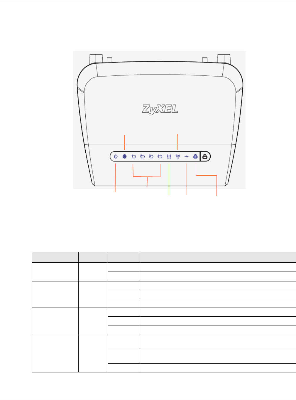
1.5 LEDs
Figure 1 Front Panel
The following table describes the LEDs and the WPS button.
Table 1 Front Panel LEDs and WPS Button
LED COLOR STATUS DESCRIPTION
POWER Green On The NBG is receiving power and functioning properly.
Off The NBG is not receiving power.
WAN Green On The NBG has a successful 10/100/1000MB WAN connection.
Blinking The NBG is sending/receiving data through the WAN.
Off The WAN connection is not ready, or has failed.
LAN 1-4 Green On The NBG has a successful 10/100/1000MB Ethernet connection.
Blinking The NBG is sending/receiving data through the LAN.
Off The LAN is not connected.
WLAN 2.4 GHz Green On The NBG is ready, but is not sending/receiving data through the
wireless LAN 2.4 GHz band.
Blinking The NBG is sending/receiving data through the wireless LAN 2.4
GHz band.
Off The wireless LAN 2.4 GHz band is not ready or has failed.
Power LAN 1-4 WLAN
WLAN
WPS
WAN 5GHz
2.4GHz USB

Chapter 1 Getting to Know Your NBG
NBG6515 User’s Guide
15
1.6 The WPS Button
Your NBG supports WiFi Protected Setup (WPS), which is an easy way to set up a secure wireless
network. WPS is an industry standard specification, defined by the WiFi Alliance.
WPS allows you to quickly set up a wireless network with strong security, without having to
configure security settings manually. Each WPS connection works between two devices. Both
devices must support WPS (check each device’s documentation to make sure).
Depending on the devices you have, you can either press a button (on the device itself, or in its
configuration utility) or enter a PIN (a unique Personal Identification Number that allows one device
to authenticate the other) in each of the two devices. When WPS is activated on a device, it has two
minutes to find another device that also has WPS activated. Then, the two devices connect and set
up a secure network by themselves.
For more information on using WPS, see Section 10.3 on page 72.
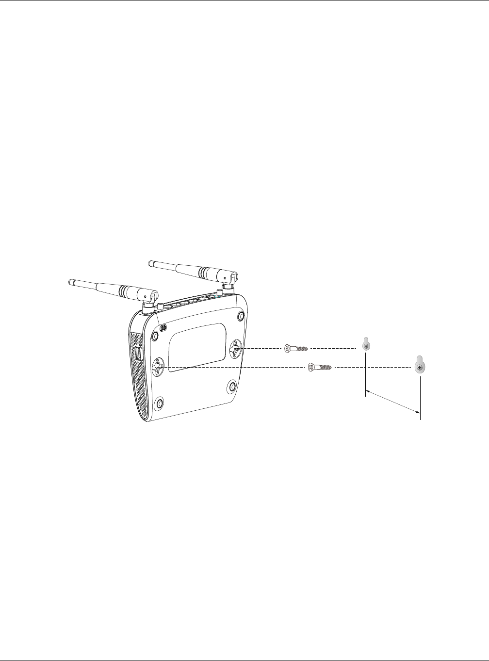
1.7 Wall Mounting
You may need screw anchors if mounting on a concrete or brick wall.
1Select a position free of obstructions on a wall strong enough to hold the weight of the
device.
2Mark two holes on the wall at the appropriate distance apart for the screws.
WLAN 5 GHz Green On The NBG is ready, but is not sending/receiving data through the
wireless LAN 5 GHz band.
Blinking The NBG is sending/receiving data through the wireless LAN
5 GHz band.
Off The wireless LAN 5 GHz band is not ready or has failed.
USB Green On The NBG has a USB device installed.
Blinking The NBG is transmitting and/or receiving data from routers
through an installed USB device.
Off There is no USB device connected to the NBG.
WPS Green On WPS is enabled.
Blinking The NBG is negotiating a WPS connection with a wireless client.
Off The wireless LAN is not ready or has failed.
Table 1 Front Panel LEDs and WPS Button (continued)
LED COLOR STATUS DESCRIPTION
Table 2 Wall Mounting Information
Distance between holes 11 cm
M4 Screws Two
Screw anchors (optional) Two
Chapter 1 Getting to Know Your NBG
NBG6515 User’s Guide
16
Be careful to avoid damaging pipes or cables located inside the wall
when drilling holes for the screws.
3If using screw anchors, drill two holes for the screw anchors into the wall. Push the
anchors into the full depth of the holes, then insert the screws into the anchors. Do not
insert the screws all the way in - leave a small gap of about 0.5 cm.
If not using screw anchors, use a screwdriver to insert the screws into the wall. Do not
insert the screws all the way in - leave a gap of about 0.5 cm.
4Make sure the screws are fastened well enough to hold the weight of the NBG with the
connection cables.
5Align the holes on the back of the NBG with the screws on the wall. Hang the NBG on the
screws.
Figure 2 Wall Mounting Example
NBG6515 User’s Guide
17
CHAPTER 2
Connection Wizard
2.1 Overview
This chapter provides information on the wizard setup screens in the Web Configurator.
The Web Configurator’s wizard setup helps you configure your device to access the Internet. Refer
to your ISP for your Internet account information. Leave a field blank if you don’t have that
information.
2.2 Accessing the Wizard
Launch your web browser and type "http://192.168.1.1" as the website address. Type "1234"
(default) as the password and click Login.
Note: The Wizard appears when the NBG is accessed for the first time or when you reset
the NBG to its default factory settings.
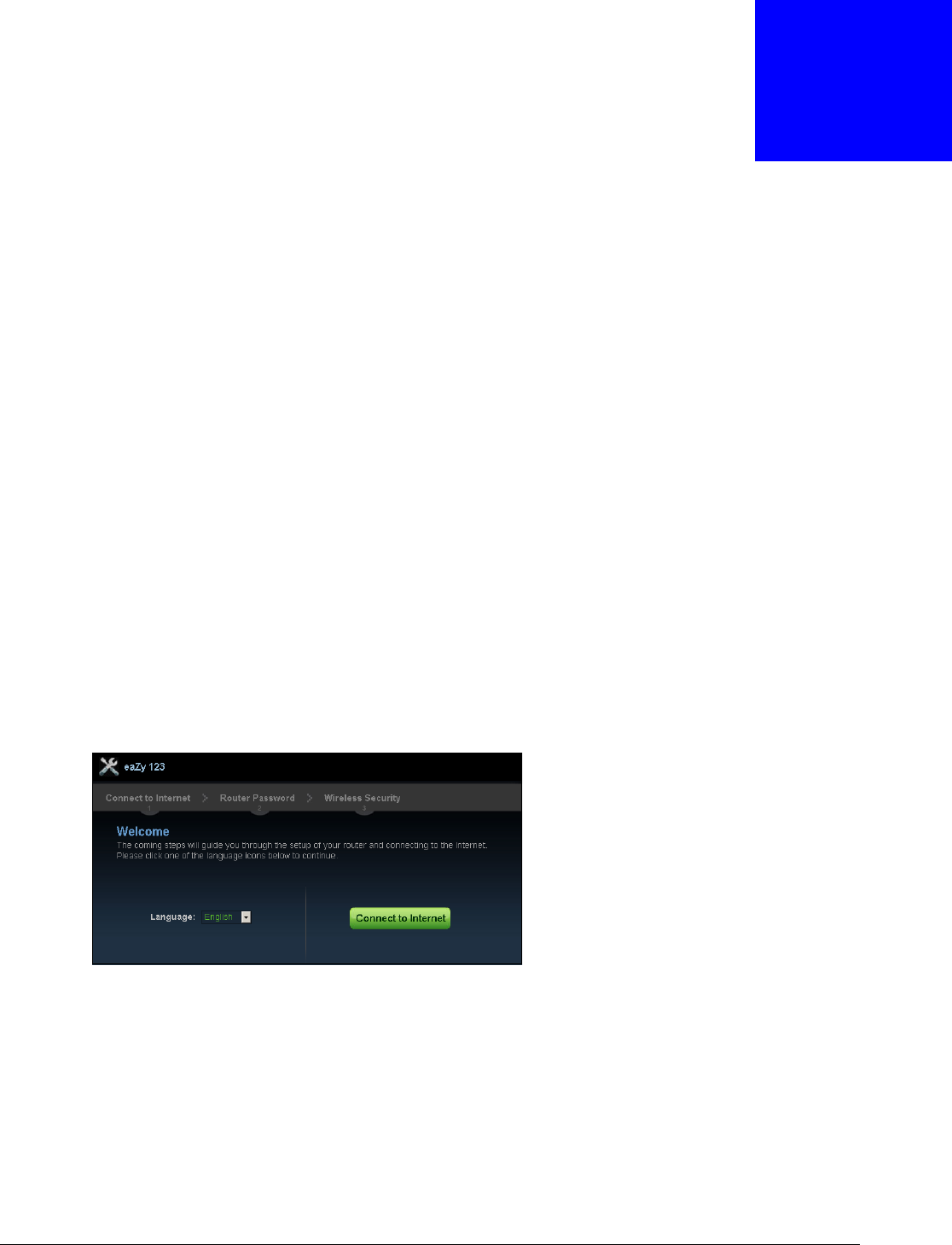
The Wizard screen opens. Choose your Language and click Connect to Internet.
Figure 3 Welcome
2.3 Connect to Internet
The NBG offers four Internet connection types. They are Static IP, DHCP, PPPoE, or PPTP
(supported in the next firmware version). The wizard attempts to detect which WAN connection
type you are using.
Chapter 2 Connection Wizard
NBG6515 User’s Guide
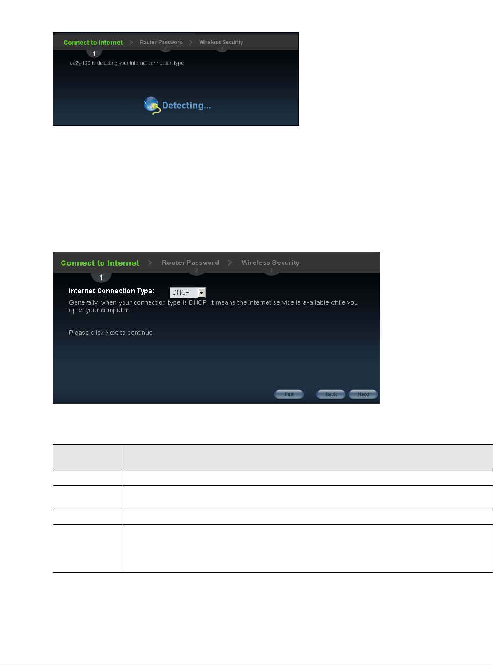
18
Figure 4 Detecting your Internet Connection Type
If the wizard does not detect a connection type, you must select one from the drop-down list box.
Check with your ISP to make sure you use the correct type.
Note: If you get an error message, check your hardware connections. Make sure your
Internet connection is up and running.
The following screen depends on your Internet connection type. Enter the details provided by your
Internet Service Provider (ISP) in the fields (if any).
Figure 5 Internet Connection Type
Your NBG detects the following Internet Connection type.
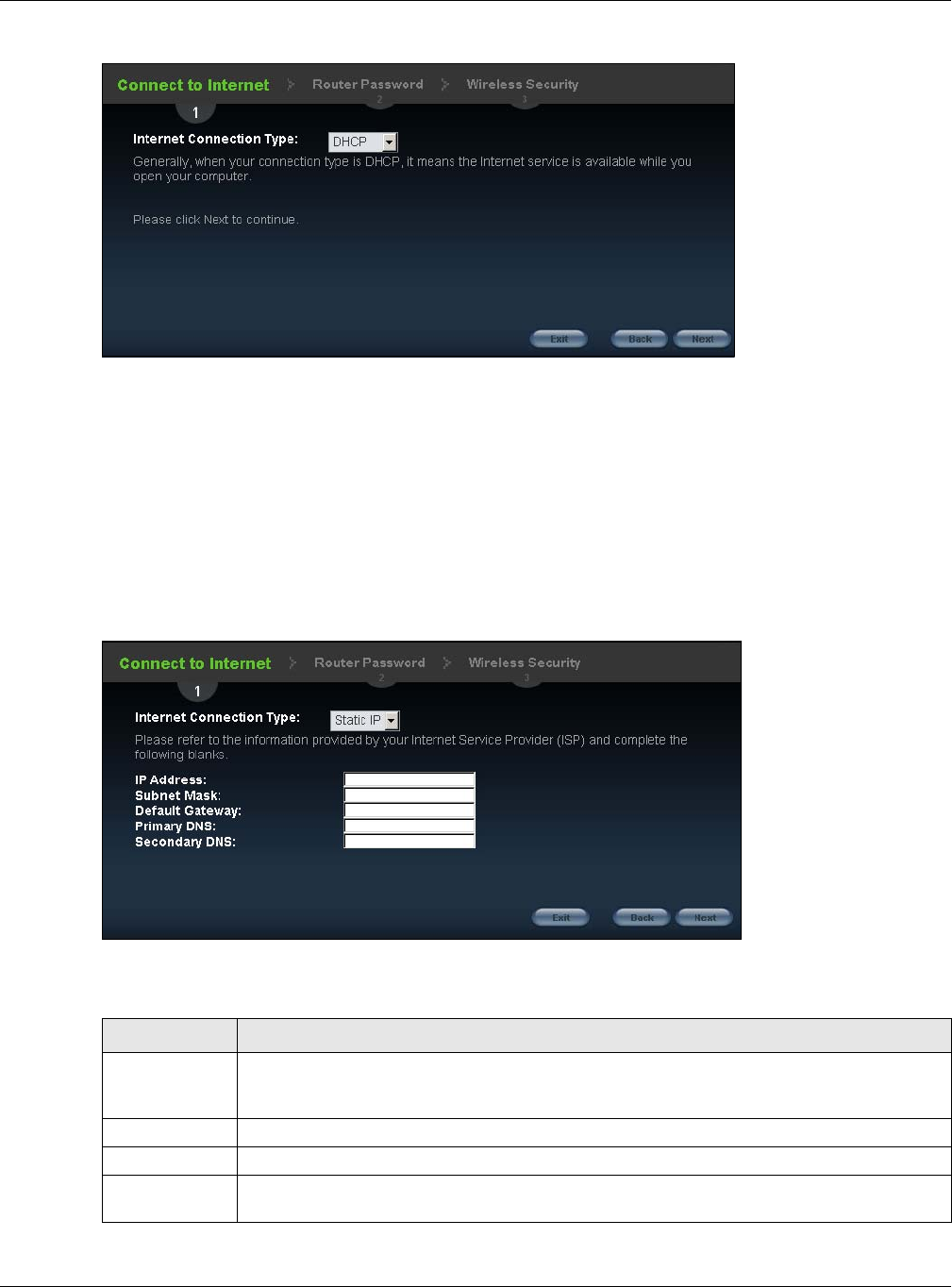
2.3.1 Connection Type: DHCP
Choose DHCP as the Internet Connection Type when the WAN port is used as a regular
Ethernet. Click Next.
Table 3 Internet Connection Type
CONNECTION
TYPE DESCRIPTION
Static IP Select the Static IP if an administrator assigns the IP address of your computer.
DHCP Select the DHCP (Dynamic Host Configuration Protocol) option when the WAN port is used
as a regular Ethernet.
PPPoE Select the PPPoE (Point-to-Point Protocol over Ethernet) option for a dial-up connection.
PPTP Select the PPTP (Point-to-Point Tunneling Protocol) option for a dial-up connection, and
your ISP gave you an IP address and/or subnet mask.
Note: PPTP will be supported in the next firmware version.
Chapter 2 Connection Wizard
NBG6515 User’s Guide
19
Figure 6 Internet Connection Type: DHCP
Note: If you get an error screen after clicking Next, you might have selected the wrong
Internet Connection type. Click Back, make sure your Internet connection is
working and select the right Connection Type. Contact your ISP if you are not sure
of your Internet Connection type.
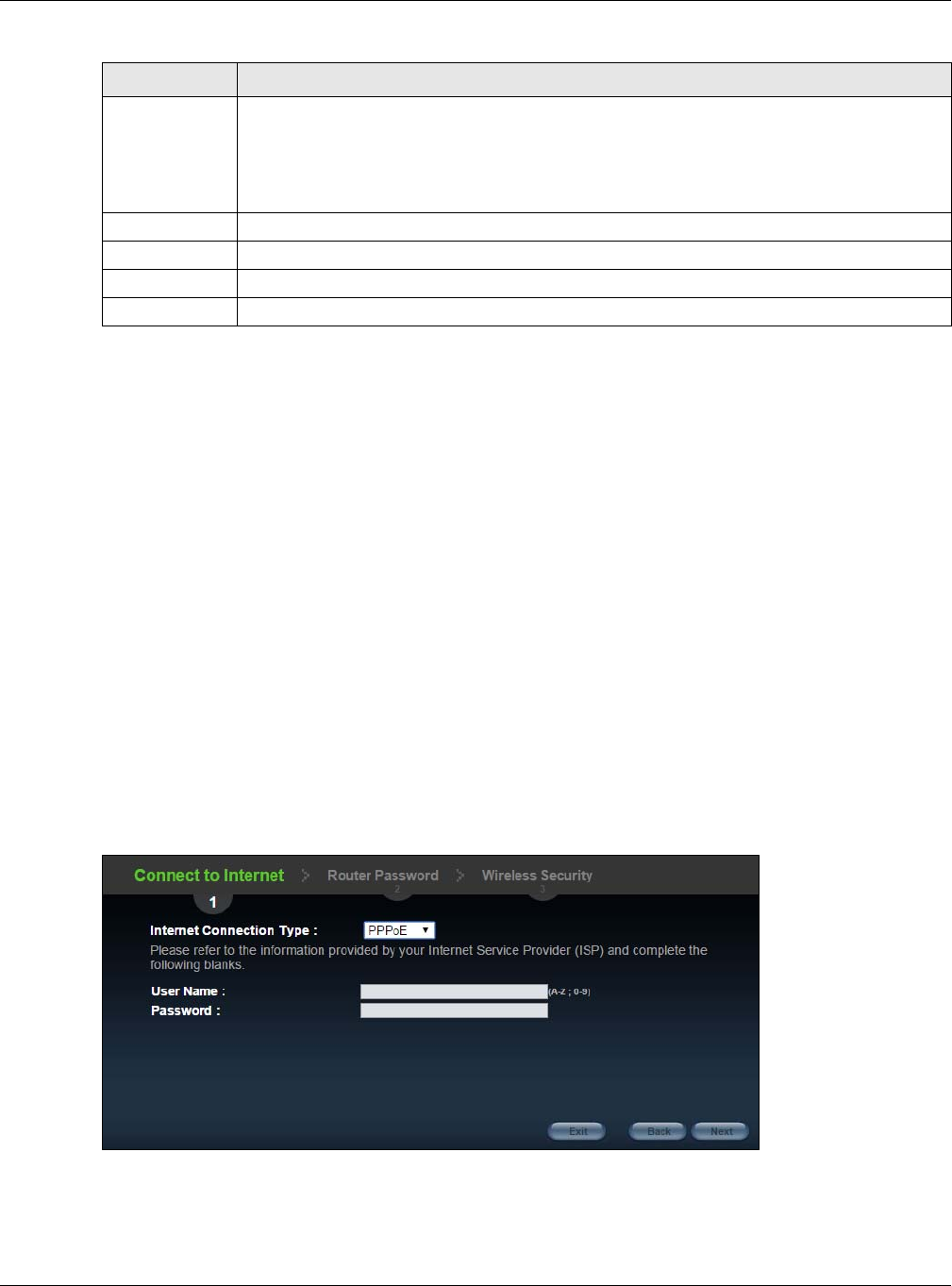
2.3.2 Connection Type: Static IP
Choose Static IP as the Internet Connection Type if your ISP assigned an IP address for your
Internet connection. Click Next.
Figure 7 Internet Connection Type: Static IP
The following table describes the labels in this screen.
Table 4 Internet Connection Type: Static IP
LABEL DESCRIPTION
Internet
Connection
Type
Select the Static IP option.
IP Address Enter the IP address provided by your ISP.
Subnet Mask Enter the IP subnet mask in this field.
Default
Gateway
Enter the gateway IP address in this field.
Chapter 2 Connection Wizard
NBG6515 User’s Guide
20
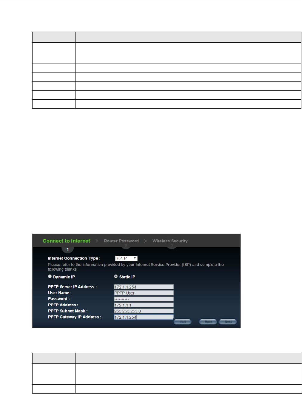
2.3.3 Connection Type: PPPoE
Point-to-Point Protocol over Ethernet (PPPoE) functions as a dial-up connection. PPPoE is an IETF
(Internet Engineering Task Force) standard specifying how a host personal computer interacts with
a broadband modem (for example DSL, cable, wireless, etc.) to achieve access to high-speed data
networks.
For the service provider, PPPoE offers an access and authentication method that works with existing
access control systems (for instance, RADIUS).
One of the benefits of PPPoE is the ability to let end users access one of multiple network services,
a function known as dynamic service selection. This enables the service provider to easily create
and offer new IP services for specific users.
Operationally, PPPoE saves significant effort for both the subscriber and the ISP/carrier, as it
requires no specific configuration of the broadband modem at the subscriber's site.
By implementing PPPoE directly on the NBG (rather than individual computers), the computers on
the LAN do not need PPPoE software installed, since the NBG does that part of the task.
Furthermore, with NAT, all of the LAN's computers will have Internet access.
Figure 8 Internet Connection Type: PPPoE
Primary DNS DNS (Domain Name System) is for mapping a domain name to its corresponding IP address
and vice versa. The DNS server is extremely important because without it, you must know
the IP address of a computer before you can access it. The NBG uses a system DNS server
(in the order you specify here) to resolve domain names for DDNS and the time server.
Enter the primary DNS server's IP address in the fields provided.
Secondary DNS Enter the secondary DNS server's IP address in the fields provided.
Exit Click this to close the wizard screen without saving.
Back Click this to return to the previous screen.
Next Click this to continue.
Table 4 Internet Connection Type: Static IP (continued)
LABEL DESCRIPTION
Chapter 2 Connection Wizard
NBG6515 User’s Guide
21
The following table describes the labels in this screen.
2.3.4 Connection Type: PPTP
Point-to-Point Tunneling Protocol (PPTP) is a network protocol that enables transfers of data from a
remote client to a private server, creating a Virtual Private Network (VPN) using TCP/IP-based
networks.
PPTP supports on-demand, multi-protocol, and virtual private networking over public networks,
such as the Internet.
Refer to the appendix for more information on PPTP.
The NBG supports one PPTP server connection at any given time.
Note: This Internet connection type will be supported in the next firmware version.
Figure 9 Internet Connection Type: PPTP
The following table describes the fields in this screen
Table 5 Internet Connection Type: PPPoE
LABEL DESCRIPTION
Internet
Connection
Type
Select the PPPoE option for a dial-up connection.
User Name Type the user name given to you by your ISP.
Password Type the password associated with the user name above.
Exit Click this to close the wizard screen without saving.
Back Click this to return to the previous screen.
Next Click this to continue.
Table 6 Internet Connection Type: PPTP
LABEL DESCRIPTION
Internet
Connection
Type
Select PPTP from the drop-down list box. To configure a PPTP client, you must configure the
User Name and Password fields for a PPP connection and the PPTP parameters for a PPTP
connection.
Dynamic IP Select this radio button if your ISP did not assign you a fixed IP address.
Chapter 2 Connection Wizard
NBG6515 User’s Guide
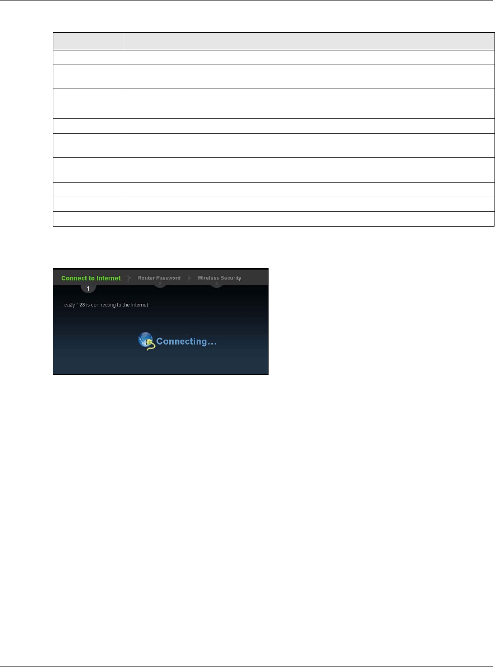
22
The NBG connects to the Internet.
Figure 10 Connecting to the Internet
Note: If the Wizard successfully connects to the Internet, it proceeds to the next step. If
you get an error message, go back to the previous screen and make sure you have
entered the correct information provided by your ISP.
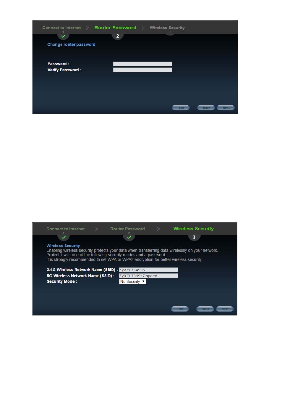
2.4 Router Password
Change the login password in the following screen. Enter the new password and retype it to
confirm. Click Next to proceed with the Wireless Security screen.
Static IP Select this radio button, provided by your ISP to give the NBG a fixed, unique IP address.
PPTP Server IP
Address
Type the server IP address of the PPTP server.
User Name Type the user name given to you by your ISP.
Password Type the password associated with the User Name above.
PPTP Address Type the (static) IP address assigned to you by your ISP.
PPTP Subnet
Mask
Type the subnet mask assigned to you by your ISP (if given).
PPTP Gateway
IP Address
Type the gateway IP address of the PPTP server.
Exit Click this to close the wizard screen without saving.
Back Click this to return to the previous screen.
Next Click this to continue.
Table 6 Internet Connection Type: PPTP (continued)
LABEL DESCRIPTION
Chapter 2 Connection Wizard
NBG6515 User’s Guide
23
Figure 11 Router Password
2.5 Wireless Security
Configure Wireless Settings. Configure the wireless network settings on your NBG in the following
screen. The fields that show up depend on the kind of security you select.
2.5.1 Wireless Security: No Security
Choose No Security in the Wireless Security screen to let wireless devices within range access
your wireless network.
Figure 12 Wireless Security: No Security
Chapter 2 Connection Wizard
NBG6515 User’s Guide
24
The following table describes the labels in this screen.
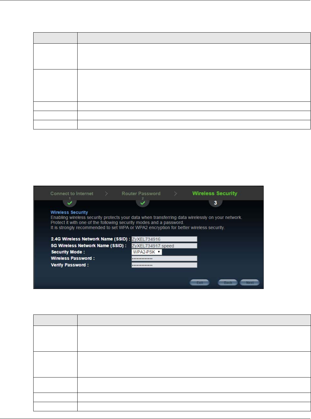
2.5.2 Wireless Security: WPA-PSK/WPA2-PSK
Choose WPA-PSK or WPA2-PSK security in the Wireless Security screen to set up a password for
your wireless network.
Figure 13 Wireless Security: WPA-PSK/WPA2-PSK
The following table describes the labels in this screen.
Table 7 Wireless Security: No Security
LABEL DESCRIPTION
Wireless
Network Name
(SSID)
Enter a descriptive name (up to 32 printable 7-bit ASCII characters) for the wireless LAN.
If you change this field on the NBG, make sure all wireless stations use the same SSID in
order to access the network.
Security mode Select a Security level from the drop-down list box.
Choose None to have no wireless LAN security configured. If you do not enable any wireless
security on your NBG, your network is accessible to any wireless networking device that is
within range.
Exit Click this to close the wizard screen without saving.
Back Click this to return to the previous screen.
Next Click this to continue.
Table 8 Wireless Security: WPA-PSK/WPA2-PSK
LABEL DESCRIPTION
Wireless
Network Name
(SSID)
Enter a descriptive name (up to 32 printable 7-bit ASCII characters) for the wireless LAN.
If you change this field on the NBG, make sure all wireless stations use the same SSID in
order to access the network.
Security mode Select a Security level from the drop-down list box.
Choose WPA-PSK or WPA2-PSK security to configure a Pre-Shared Key. Choose this
option only if your wireless clients support WPA-PSK or WPA2-PSK respectively.
Wireless
password
Type from 8 to 63 case-sensitive ASCII characters. You can set up the most secure wireless
connection by configuring WPA in the wireless LAN screens.
Verify Password Retype the password to confirm.
Exit Click this to close the wizard screen without saving.
Chapter 2 Connection Wizard
NBG6515 User’s Guide
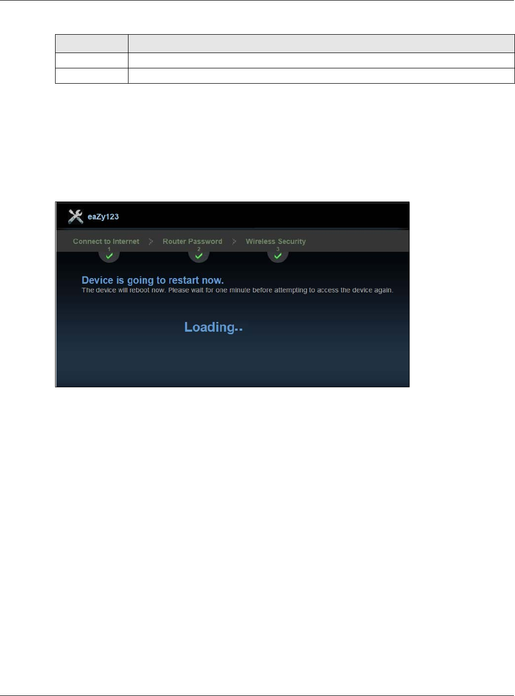
25
Congratulations! Open a web browser, such as Internet Explorer, to visit your favorite website.
Note: If you cannot access the Internet when your computer is connected to one of the
NBG’s LAN ports, check your connections. Then turn the NBG off, wait for a few
seconds then turn it back on. If that does not work, log in to the web configurator
again and check you have typed all information correctly. See the User’s Guide for
more suggestions.
Figure 14 Device is going to restart now
You can also click GO to open the Easy Mode Web Configurator of your NBG.
You have successfully set up your NBG to operate on your network and access the Internet. You are
now ready to connect wirelessly to your NBG and access the Internet.
Back Click this to return to the previous screen.
Next Click this to continue.
Table 8 Wireless Security: WPA-PSK/WPA2-PSK (continued)
LABEL DESCRIPTION

NBG6515 User’s Guide
26
CHAPTER 3
Introducing the Web Configurator
3.1 Overview
This chapter describes how to access the NBG Web Configurator and provides an overview of its
screens.
The Web Configurator is an HTML-based management interface that allows easy setup and
management of the NBG via Internet browser. Use Internet Explorer 6.0 and later or Netscape
Navigator 7.0 and later versions or Safari 2.0 or later versions. The recommended screen resolution
is 1024 by 768 pixels.
In order to use the Web Configurator you need to allow:
• Web browser pop-up windows from your device. Web pop-up blocking is enabled by default in
Windows XP SP (Service Pack) 2.
• JavaScript (enabled by default).
• Java permissions (enabled by default).
Refer to the Troubleshooting chapter (Chapter 26 on page 167) to see how to make sure these
functions are allowed in Internet Explorer.
3.2 Accessing the Web Configurator
1Make sure your NBG hardware is properly connected and prepare your computer or computer
network to connect to the NBG (refer to the Quick Start Guide).
2Launch your web browser.
3Type "http://192.168.1.1" as the website address.
Your computer must be in the same subnet in order to access this website address.
3.2.1 Login Screen
Note: If this is the first time you are accessing the Web Configurator, you may be
redirected to the Wizard. Refer to Chapter 2 on page 17 for the Connection Wizard
screens.
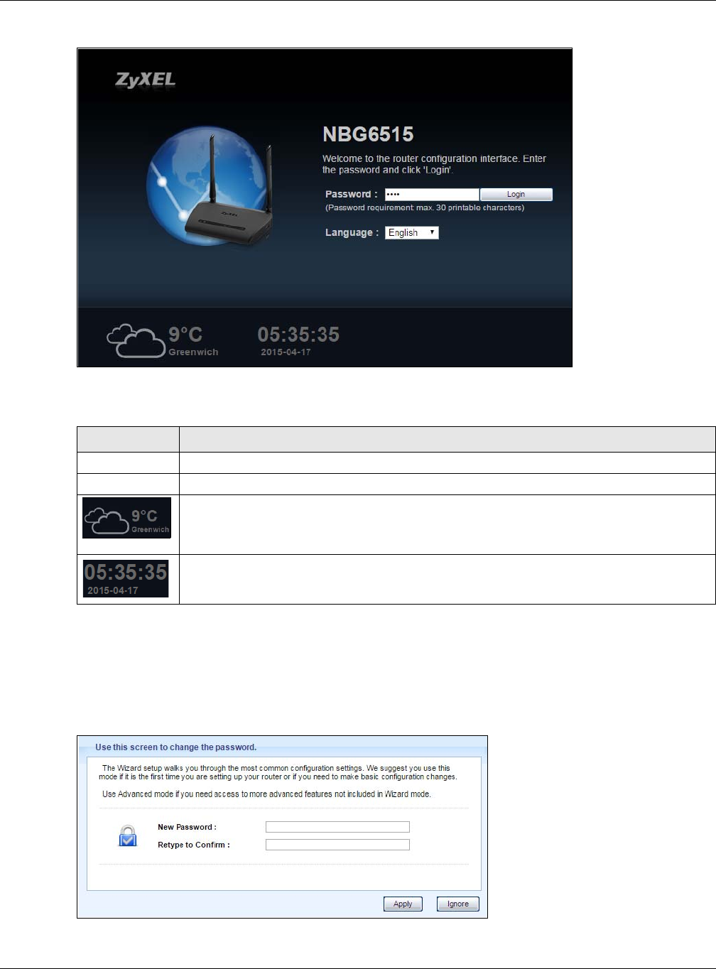
The Web Configurator initially displays the following login screen.
Chapter 3 Introducing the Web Configurator
NBG6515 User’s Guide
27
Figure 15 Login screen
The following table describes the labels in this screen.
3.2.2 Password Screen
You should see a screen asking you to change your password (highly recommended) as shown
next.
Figure 16 Change Password Screen
Table 9 Login screen
LABEL DESCRIPTION
Password Type "1234" (default) as the password.
Language Select the language you want to use to configure the Web Configurator. Click Login.
This shows the current weather, either in celsius or fahrenheit, of the city you specify in
Section 3.2.3.1 on page 29.
This shows the time (hh:mm:ss) and date (yyyy:mm:dd) of the timezone you select in
Section 3.2.3.2 on page 29 or Section 25.5 on page 162. The time is in 24-hour format, for
example 15:00 is 3:00 PM.
Chapter 3 Introducing the Web Configurator
NBG6515 User’s Guide
28
The following table describes the labels in this screen.
Note: The management session automatically times out when the time period set in the
Administrator Inactivity Timer field expires (default five minutes; go to Chapter
25 on page 160 to change this). Simply log back into the NBG if this happens.
3.2.3 Home Screen
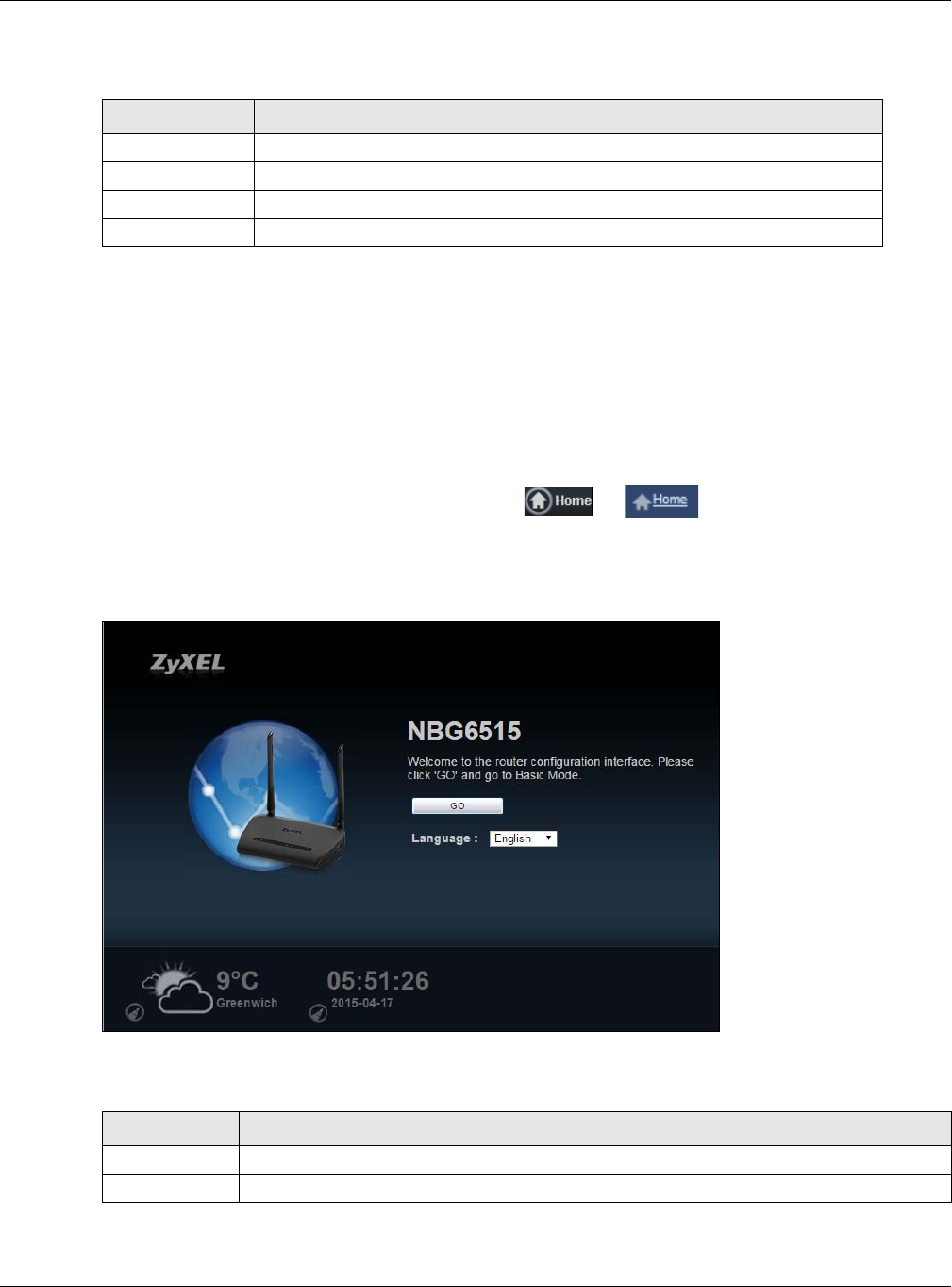
If you have previously logged into the Web Configurator but did not click Logout, you may be
redirected to the Home screen.
You can also open this screen by clicking Home ( or ) in the Easy Mode or Expert
mode screens.
The Home screen displays as follows.
Figure 17 Home Screen
The following table describes the labels in this screen.
Table 10 Change Password Screen
LABEL DESCRIPTION
New Password Type a new password.
Retype to Confirm Retype the password for confirmation.
Apply Click Apply to save your changes back to the NBG.
Ignore Click Ignore if you do not want to change the password this time.
Table 11 Home Screen
LABEL DESCRIPTION
Go Click this to open the Easy mode Web Configurator.
Language Select a language to go to the Easy mode Web Configurator.
Chapter 3 Introducing the Web Configurator
NBG6515 User’s Guide
29
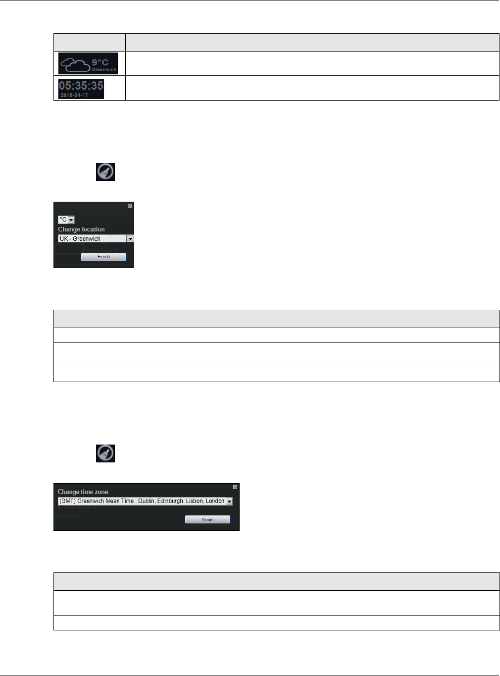
3.2.3.1 Weather Edit
You can change the temperature unit and select the location for which you want to know the
weather.
Click the icon to change the Weather display.
Figure 18 Change Weather
The following table describes the labels in this screen.
3.2.3.2 Time/Date Edit
One timezone can cover more than one country. You can choose a particular country in which the
NBG is located and have the NBG display and use the current time and date for its logs.
Click the icon to change the Weather display.
Figure 19 Change Password Screen
The following table describes the labels in this screen.
Note: You can also edit the timezone in Section 25.5 on page 162.
(This is just an example). This shows the current weather, either in celsius or fahrenheit, of
the city you specify in Section 3.2.3.1 on page 29.
(This is just an example). This shows the time (hh:mm:ss) and date (yyyy:mm:dd) of the
timezone you select in Section 3.2.3.2 on page 29 or Section 25.5 on page 162.
Table 11 Home Screen (continued)
LABEL DESCRIPTION
Table 12 Change Weather
LABEL DESCRIPTION
oC or oF Choose which temperature unit you want the NBG to display.
Change
Location
Select the location for which you want to know the weather. If the city you want is not listed,
choose one that is closest to it.
Finish Click this to apply the settings and refresh the date and time display.
Table 13 Change Password Screen
LABEL DESCRIPTION
Change time
zone
Select the specific country whose current time and date you want the NBG to display.
Finish Click this to apply the settings and refresh the weather display.

Chapter 3 Introducing the Web Configurator
NBG6515 User’s Guide
30
3.3 Resetting the NBG
If you forget your password or IP address, or you cannot access the Web Configurator, you will need
to use the RESET button at the back of the NBG to reload the factory-default configuration file. This
means that you will lose all configurations that you had previously saved, the password will be reset
to “1234” and the IP address will be reset to “192.168.1.1”.
3.3.1 Procedure to Use the Reset Button
1Make sure the power LED is on.
2Press the RESET button for longer than 1 second to restart/reboot the NBG.
3Press the RESET button for longer than five seconds to set the NBG back to its factory-default
configurations.

NBG6515 User’s Guide
31
CHAPTER 4
Monitor
4.1 Overview
This chapter discusses read-only information related to the device state of the NBG.
Note: To access the Monitor screens, you can also click the links in the Summary table of
the Status screen to view the bandwidth consumed, packets sent/received as well
as the status of clients connected to the NBG.
4.2 What You Can Do
•Use the Log (Section 4.3 on page 31) screen to see the logs for the activity on the NBG.
•Use the DHCP Table screen (Section 4.4 on page 32) to view information related to your DHCP
status.
•Use the Packet Statistics screen (Section 4.5 on page 33) to view port status, packet specific
statistics, the "system up time" and so on.
•Use the WLAN 2.4G Station Status screen (Section 4.6 on page 34) to view the wireless
stations that are currently associated to the NBG through the wireless 2.4G network.
•Use the WLAN 5G Station Status screen (Section 4.7 on page 35) to view the wireless stations
that are currently associated to the NBG through the wireless 5G network.
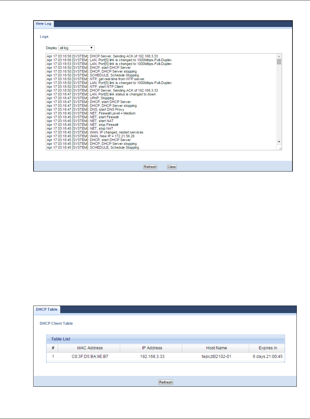
4.3 The Log Screen
The Web Configurator allows you to look at all of the NBG’s logs in one location.
4.3.1 View Log
Use the View Log screen to see the logged messages for the NBG. The log wraps around and
deletes the old entries after it fills. Select what logs you want to see from the Display drop list.
Click Refresh to renew the log screen. Click Clear to delete all the logs.
Chapter 4 Monitor
NBG6515 User’s Guide
32
Figure 20 View Log
You can configure which logs to display in the View Log screen.
4.4 DHCP Table
DHCP (Dynamic Host Configuration Protocol, RFC 2131 and RFC 2132) allows individual clients to
obtain TCP/IP configuration at start-up from a server. You can configure the NBG’s LAN as a DHCP
server or disable it. When configured as a server, the NBG provides the TCP/IP configuration for the
clients. If DHCP service is disabled, you must have another DHCP server on that network, or else
the computer must be manually configured.
Click the DHCP Table (Details...) hyperlink in the Status screen. Read-only information here
relates to your DHCP status. The DHCP table shows current DHCP client information (including IP
Address, Host Name and MAC Address) of all network clients using the NBG’s DHCP server.
Figure 21 Summary: DHCP Table
Chapter 4 Monitor
NBG6515 User’s Guide
33
The following table describes the labels in this screen.
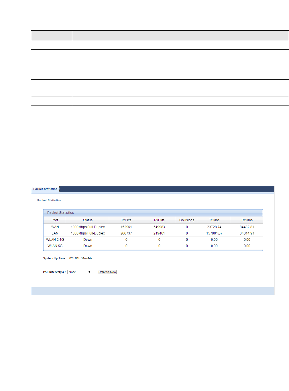
4.5 Packet Statistics
Click the Packet Statistics (Details...) hyperlink in the Status screen. Read-only information
here includes port status, packet specific statistics and the "system up time". The Poll Interval(s)
field is configurable and is used for refreshing the screen.
Figure 22 Summary: Packet Statistics
Table 14 Summary: DHCP Table
LABEL DESCRIPTION
# This is the index number of the host computer.
MAC Address This field shows the MAC address of the computer with the name in the Host Name field.
Every Ethernet device has a unique MAC (Media Access Control) address which uniquely
identifies a device. The MAC address is assigned at the factory and consists of six pairs of
hexadecimal characters, for example, 00:A0:C5:00:00:02.
IP Address This field displays the IP address relative to the # field listed above.
Host Name This field displays the computer host name.
Expires in This field displays the time when the IP address and MAC address association ends.
Refresh Click Refresh to renew the screen.
Chapter 4 Monitor
NBG6515 User’s Guide
34
The following table describes the labels in this screen.
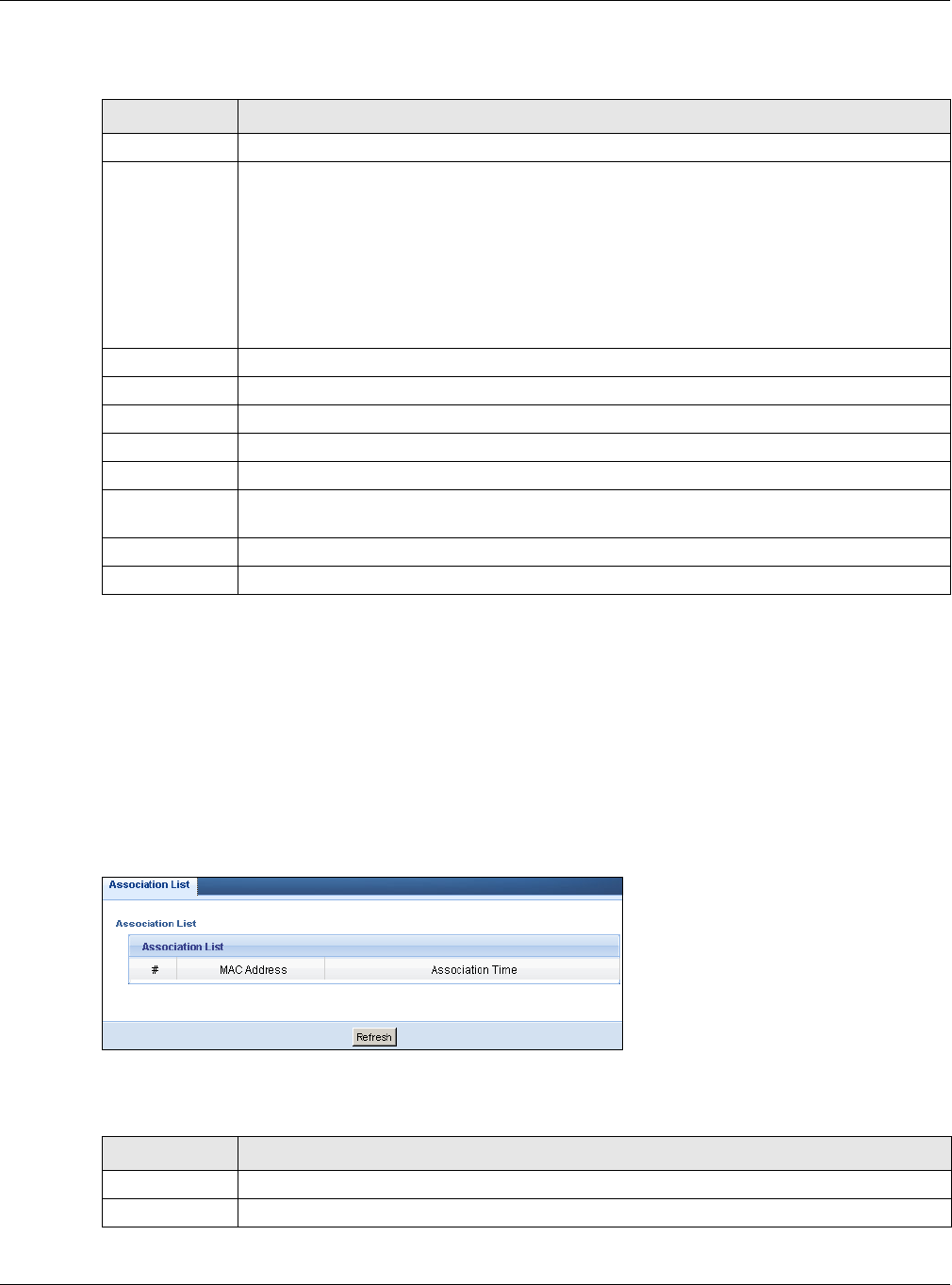
4.6 WLAN 2.4G Station Status
Click the WLAN 2.4G Station Status (Details...) hyperlink in the Status screen. View the
wireless stations that are currently associated to the NBG in the Association List. Association
means that a wireless client (for example, your network or computer with a wireless network card)
has connected successfully to the AP (or wireless router) using the same SSID, channel and
security settings.
Figure 23 Summary: Wireless Association List
The following table describes the labels in this screen.
Table 15 Summary: Packet Statistics
LABEL DESCRIPTION
Port This is the NBG’s port type.
Status For the LAN ports, this displays the port speed and duplex setting or Down when the line is
disconnected.
For the WAN port, it displays the port speed and duplex setting if you’re using Ethernet
encapsulation and Idle (line (ppp) idle), Dial (starting to trigger a call) and Drop (dropping
a call) if you're using PPPoE or PPTP encapsulation. This field displays Down when the line is
disconnected.
For WLAN 2.4G/5G, it displays the maximum transmission rate when the WLAN 2.4G/5G is
enabled and Down when the WLAN 2.4G/5G is disabled.
TxPkts This is the number of transmitted packets on this port.
RxPkts This is the number of received packets on this port.
Collisions This is the number of collisions on this port.
Tx kb/s This displays the transmission speed in bytes per second on this port.
Rx kb/s This displays the reception speed in bytes per second on this port.
System Up
Time
This is the total time the NBG has been on.
Poll Interval(s) Enter the time interval in seconds for refreshing statistics in this field.
Refresh Now Click Refresh Now to renew the screen.
Table 16 Summary: Wireless Association List
LABEL DESCRIPTION
# This is the index number of an associated wireless station.
MAC Address This field displays the MAC address of an associated wireless station.
Chapter 4 Monitor
NBG6515 User’s Guide
35
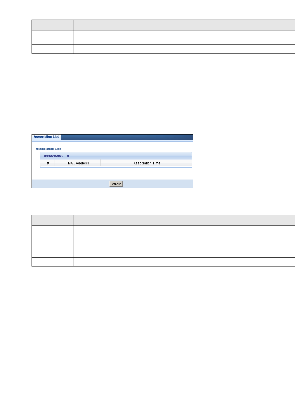
4.7 WLAN 5G Station Status
Click the WLAN 5G Station Status (Details...) hyperlink in the Status screen. View the wireless
stations that are currently associated to the NBG in the Association List. Association means that a
wireless client (for example, your network or computer with a wireless network card) has connected
successfully to the AP (or wireless router) using the same SSID, channel and security settings.
Figure 24 Summary: Wireless Association List
The following table describes the labels in this screen.
Association
Time
This field displays the time a wireless station first associated with the NBG’s WLAN network.
Refresh Click Refresh to reload the list.
Table 16 Summary: Wireless Association List (continued)
LABEL DESCRIPTION
Table 17 Summary: Wireless Association List
LABEL DESCRIPTION
# This is the index number of an associated wireless station.
MAC Address This field displays the MAC address of an associated wireless station.
Association
Time
This field displays the time a wireless station first associated with the NBG’s WLAN network.
Refresh Click Refresh to reload the list.

NBG6515 User’s Guide
36
CHAPTER 5
NBG Modes
5.1 Overview
This chapter introduces the different modes available on your NBG. First, the term “mode” refers to
two things in this User’s Guide.
•Web Configurator mode. This refers to the Web Configurator interface you want to use for
editing NBG features.
•Device mode. This is the operating mode of your NBG, or simply how the NBG is being used in
the network.
5.1.1 Web Configurator Modes
This refers to the configuration interface of the Web Configurator, which has two modes:
•Easy. The Web Configurator shows this mode by default. Refer to Chapter 6 on page 38 for more
information on the screens in this mode. This interface may be sufficient for users who just want
to use the device.
•Expert. Advanced users can change to this mode to customize all the functions of the NBG. Click
Expert Mode after logging into the Web Configurator. The User’s Guide Chapter 3 on page 26
through Chapter 25 on page 160 discusses the screens in this mode.
5.1.2 Device Modes
This refers to the operating mode of the NBG, which can act as a:
•Router. This is the default device mode of the NBG. Use this mode to connect the local network
to another network, like the Internet. Go to Section 7.3 on page 50 to view the Status screen in
this mode.
•Access Point. Use this mode if you want to extend your network by allowing network devices to
connect to the NBG wirelessly. Go to Section 8.4 on page 58 view the Status screen in this
mode.
•Universal Repeater: In this mode, the NBG can be an access point and a wireless client at the
same time. Use this mode if there is an existing wireless router or access point in your network
and you also want to allow clients to connect to the NBG. Go to Section 9.5 on page 64 to view
the Status screen in this mode.
For more information on these modes and to change the mode of your NBG, refer to Section 23.10
on page 170.
The menu for changing device modes is available in Expert mode only.
Note: Choose your Device Mode carefully to avoid having to change it later.

Chapter 5 NBG Modes
NBG6515 User’s Guide
37
When changing to another mode, the IP address of the NBG changes. The running applications and
services of the network devices connected to the NBG can be interrupted.
NBG6515 User’s Guide
38
CHAPTER 6
Easy Mode
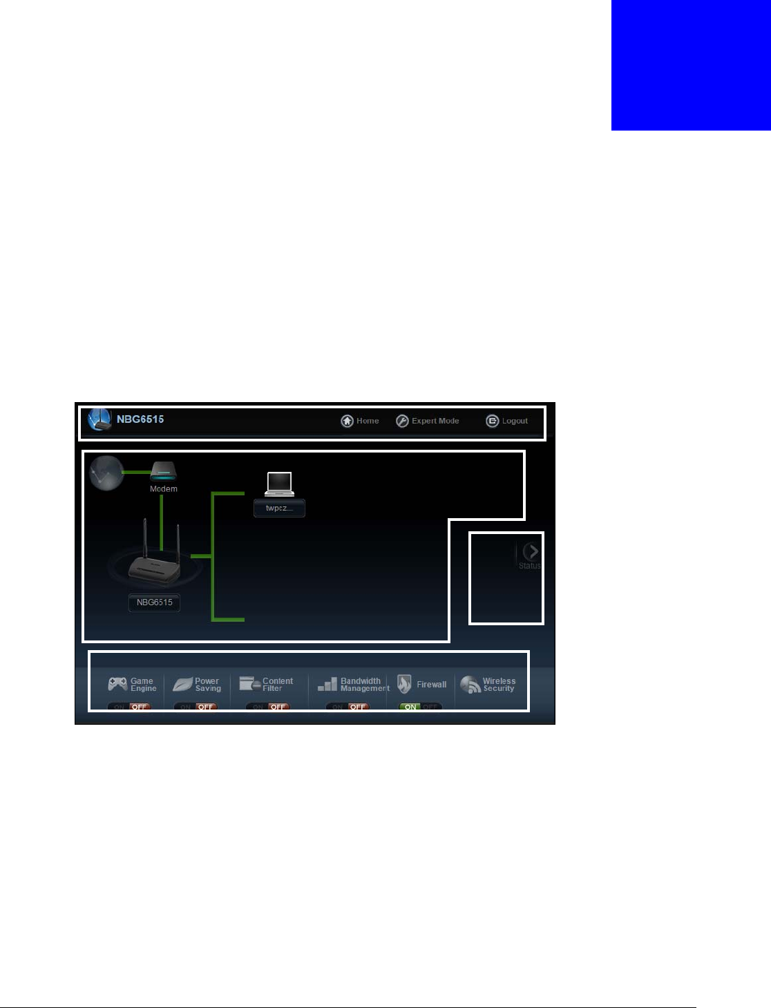
6.1 Overview
The Web Configurator is set to Easy Mode by default. You can configure several key features of the
NBG in this mode. This mode is useful to users who are not fully familiar with some features that
are usually intended for network administrators.
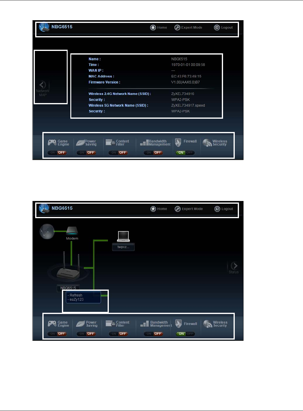
When you log in to the Web Configurator, the following screen opens.
Figure 25 Easy Mode: Network Map
Click Status to open the following screen screen.
Network Map
Control Panel
Go to
Status
Screen
Navigation Panel
Chapter 6 Easy Mode
NBG6515 User’s Guide
39
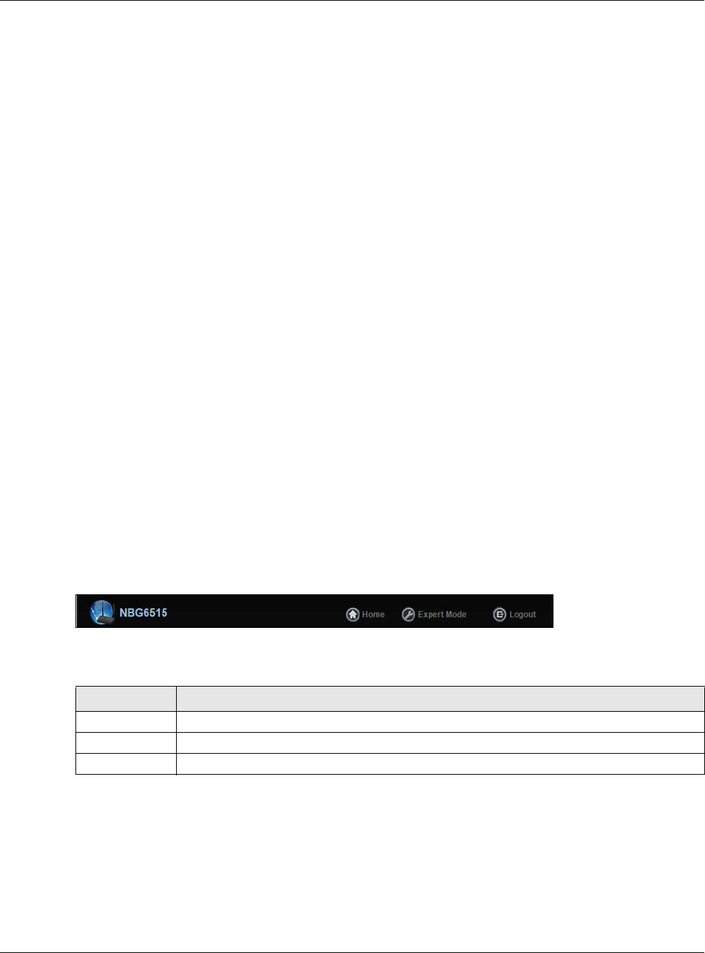
Figure 26 Easy Mode: Status Screen
Click NBG6515 to open the pop up menu.
Figure 27 Easy Mode: Pop Up Menu
Control Panel
Status Screen
Go to
Network
Map
Screen
Navigation Panel
Control Panel
Pop Up Menu
Navigation Panel
Chapter 6 Easy Mode
NBG6515 User’s Guide
40
6.2 What You Can Do
You can do the following in this mode:
•Use this Navigation Panel (Section 6.4 on page 40) to opt out of the Easy mode.
•Use the Network Map screen (Section 6.5 on page 40) to check if your NBG can ping the
gateway and whether it is connected to the Internet.
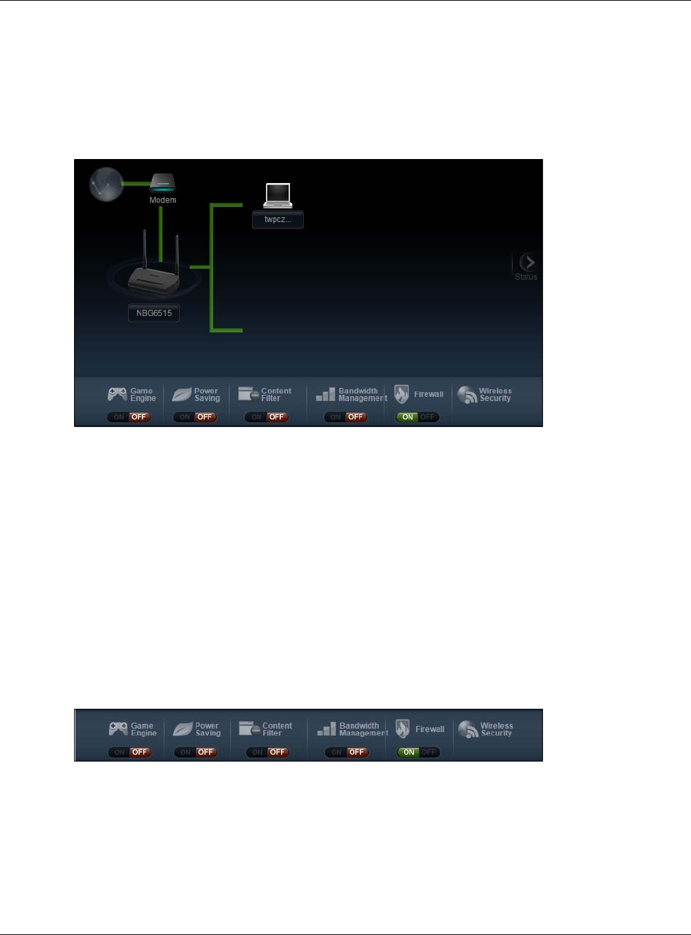
•Use the Control Panel (Section 6.6 on page 41) to configure and enable NBG features, including
wireless security, wireless scheduling and bandwidth management and so on.
•Use the Status Screen screen (Section 6.7 on page 48) to view read-only information about the
NBG, including the WAN IP, MAC Address of the NBG and the firmware version.
•Use the Pop Up Menu to refresh the Router or run the eaZy123 wizard (Section 2.2 on page
17).
6.3 What You Need to Know
Between the different device modes, the Control Panel (Section 6.6 on page 41) changes depending
on which features are applicable to the mode:
•Router Mode: All Control Panel features are available.
•Access Point Mode: Only Power Saving and Wireless Security are available.
6.4 Navigation Panel
Use this navigation panel to opt out of the Easy mode.
Figure 28 Navigation Panel
The following table describes the labels in this screen.
6.5 Network Map
Note: The Network MAP is viewable by Windows XP (need to install patch), Windows
Vista and Windows 7 users only. For Windows XP (Service Pack 2) users, you can
see the network devices connected to the NBG by downloading the LLTD (Link
Layer Topology Discovery) patch from the Microsoft Website.
Table 18 Navigation Panel
ITEM DESCRIPTION
Home Click this to go to the Login page.
Expert Mode Click this to change to Expert mode and customize features of the NBG.
Logout Click this to end the Web Configurator session.
Chapter 6 Easy Mode
NBG6515 User’s Guide
41
Note: Don’t worry if the Network Map does not display in your web browser. This feature
may not be supported by your system. You can still configure the Control Panel
(Section 6.6 on page 41) in the Easy Mode and the NBG features that you want to
use in the Expert Mode.
When you log into the Network Configurator, the Network Map is shown as follows.
Figure 29 Network Map
The line connecting the NBG to the gateway becomes green when the NBG is able to ping the
gateway. It becomes red when the ping initiating from the NBG does not get a response from the
gateway. The same rule applies to the line connecting the gateway to the Internet.
You can also view the devices (represented by icons indicating the kind of network device)
connected to the NBG, including those connecting wirelessly. Right-click on the NBG icon to refresh
the network map and go to the Wizard. Right click on the other icons to view information about the
device.
6.6 Control Panel
The features configurable in Easy Mode are shown in the Control Panel.
Figure 30 Control Panel
Switch ON to enable the feature. Otherwise, switch OFF. If the feature is turned on, the green light
flashes. If it is turned off, the red light flashes.
Additionally, click the feature to open a screen where you can edit its settings.

Chapter 6 Easy Mode
NBG6515 User’s Guide
42
The following table describes the labels in this screen.
6.6.1 Game Engine
When this feature is enabled, the NBG maximizes the bandwidth for gaming traffic that it forwards
out through an interface.
Table 19 Control Panel
ITEM DESCRIPTION
Game Engine Switch ON to maximize bandwidth for gaming traffic in your network. Otherwise, switch
OFF.
Refer to Section 6.6.1 on page 42 to see this screen.
Power Saving Click this to schedule the wireless feature of the NBG.
Disabling the wireless function helps lower the energy consumption of the NBG.
Switch ON to apply wireless scheduling. Otherwise, switch OFF.
Refer to Section 6.6.2 on page 43 to see this screen.
Content Filter Click this to restrict access to certain websites, based on keywords contained in URLs, to
which you do not want users in your network to open.
Switch ON to apply website filtering. Otherwise, switch OFF.
Refer to Section 6.6.3 on page 44 to see this screen.
Bandwidth
Management
Click this to edit bandwidth management for predefined applications.
Switch ON to have the NBG management bandwidth for uplink and downlink traffic
according to an application or service. Otherwise, switch OFF.
Refer to Section 6.6.4 on page 45 to see this screen.
Firewall Switch ON to ensure that your network is protected from Denial of Service (DoS) attacks.
Otherwise, switch OFF.
Refer to Section 6.6.5 on page 45 to see this screen.
Wireless
Security
Click this to configure the wireless security, such as SSID, security mode and WPS key on
your NBG.
Refer to Section 6.6.6 on page 46 to see this screen.
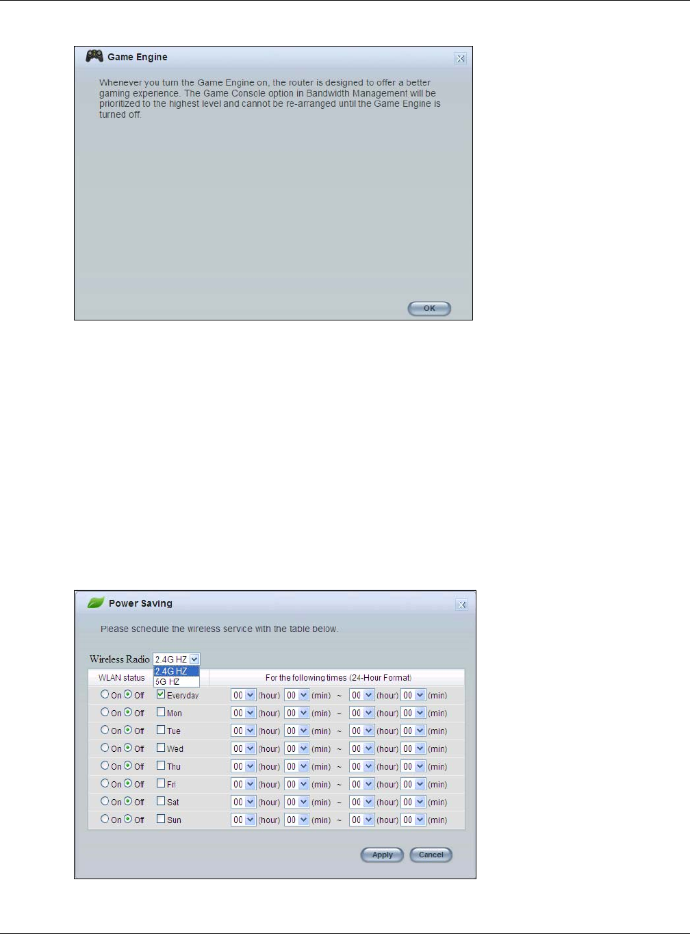
Chapter 6 Easy Mode
NBG6515 User’s Guide
43
Figure 31 Game Engine
Note: When this is switched on, the Game Console tab in the Bandwidth Management
screen is automatically positioned on top.
Turn this off if your network is not using gaming.
Click OK to close this screen.
6.6.2 Power Saving
Use this screen to set the day of the week and time of the day when your wireless LAN is turned on
and off. Wireless LAN scheduling is disabled by default.
Disabling the wireless capability lowers the energy consumption of the of the NBG.
Figure 32 Power Saving
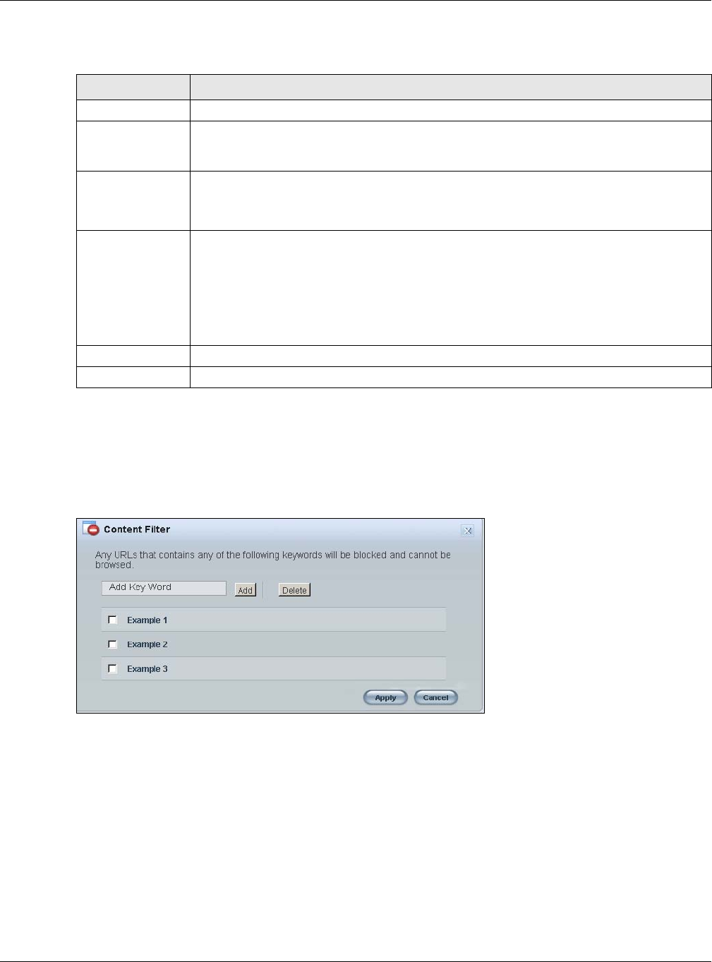
Chapter 6 Easy Mode
NBG6515 User’s Guide
44
The following table describes the labels in this screen.
6.6.3 Content Filter
Use this screen to restrict access to certain websites, based on keywords contained in URLs, to
which you do not want users in your network to open.
Figure 33 Content Filter
Table 20 Power Saving
LABEL DESCRIPTION
Wireless Radio Select the wireless radio to set its power saving settings.
WLAN Status Select On or Off to specify whether the Wireless LAN is turned on or off (depending on
what you selected in the WLAN Status field). This field works in conjunction with the
Day and Except for the following times fields.
Day Select Everyday or the specific days to turn the Wireless LAN on or off.
If you select Everyday you can not select any specific days. This field works in
conjunction with the Except for the following times field.
For the following
times (24-Hour
Format)
Select a begin time using the first set of hour and minute (min) drop down boxes and
select an end time using the second set of hour and minute (min) drop down boxes. If
you have chosen On earlier for the WLAN Status the Wireless LAN will turn on between
the two times you enter in these fields. If you have chosen Off earlier for the WLAN
Status the Wireless LAN will turn off between the two times you enter in these fields.
In this time format, midnight is 00:00 and progresses up to 24:00. For example, 6:00 PM
is 18:00.
Apply Click Apply to save your changes back to the NBG.
Cancel Click Cancel to close this screen.
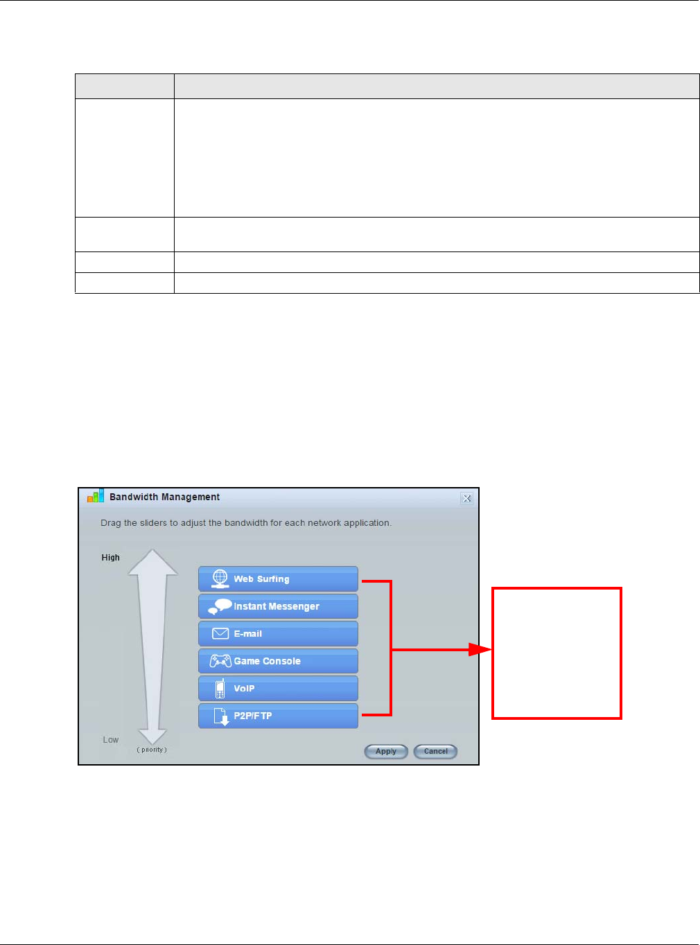
Chapter 6 Easy Mode
NBG6515 User’s Guide
45
The following table describes the labels in this screen.
6.6.4 Bandwidth Management
Use this screen to set bandwidth allocation to pre-defined services and applications for bandwidth
allocation.
The NBG uses bandwidth management for incoming and outgoing traffic. Rank the services and
applications by dragging them accordingly from High to Low and click Apply. Click Cancel to close
the screen.
Figure 34 Bandwidth Management
6.6.5 Firewall
Enable this feature to protect the network from Denial of Service (DoS) attacks. The NBG blocks
repetitive pings from the WAN that can otherwise cause systems to slow down or hang.
Table 21 Content Filter
LABEL DESCRIPTION
Add Click Add after you have typed a keyword.
Repeat this procedure to add other keywords. Up to 64 keywords are allowed.
Note: The NBG does not recognize wildcard characters as keywords.
When you try to access a web page containing a keyword, you will get a message telling you
that the content filter is blocking this request.
Delete Highlight a keyword in the text box and click Delete to remove it. The keyword disappears
from the text box after you click Apply.
Apply Click Apply to save your changes.
Cancel Click Cancel to close this screen without saving any changes.
Use your mouse
to drag the items
according to how
you want to
prioritze them.
Left-click and
slide up or down.
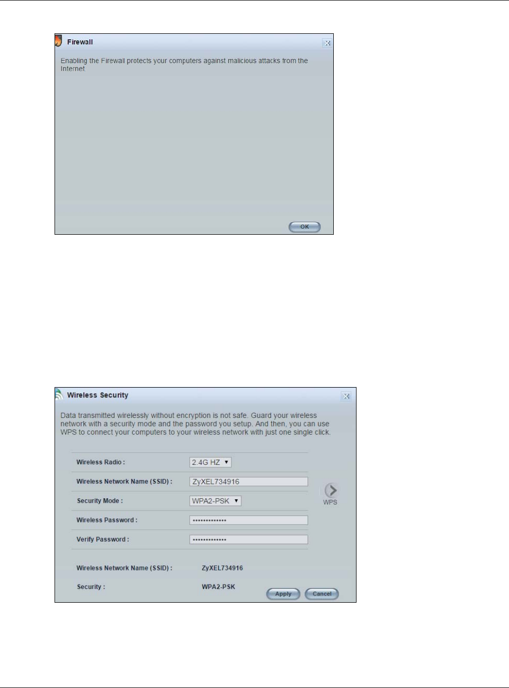
Chapter 6 Easy Mode
NBG6515 User’s Guide
46
Figure 35 Firewall
Click OK to close this screen.
6.6.6 Wireless Security
Use this screen to configure security for your the Wireless LAN. You can enter the SSID and select
the wireless security mode in the following screen.
Note: You can enable the Wireless function of your NBG by first turning on the switch in
the back panel.
Figure 36 Wireless Security
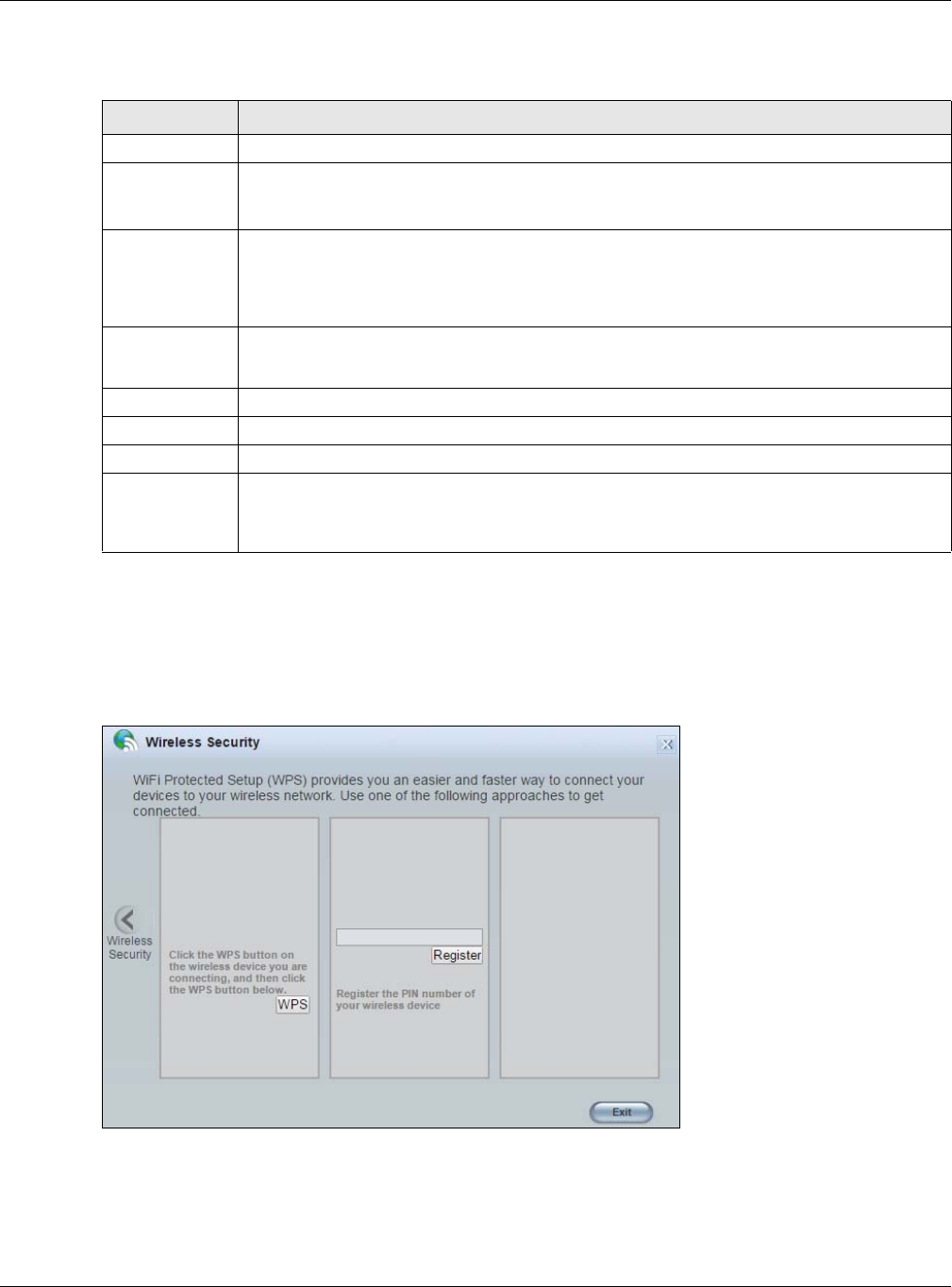
Chapter 6 Easy Mode
NBG6515 User’s Guide
47
The following table describes the general wireless LAN labels in this screen.
6.6.7 WPS
Use this screen to add a wireless station to the network using WPS. Click WPS in the Wireless
Security to open the following screen.
Figure 37 Wireless Security: WPS
Table 22 Wireless Security
LABEL DESCRIPTION
Wireless Radio Select the wireless radio to set its security setting.
Wireless
Network Name
(SSID)
(Service Set IDentity) The SSID identifies the Service Set with which a wireless station is
associated. Wireless stations associating to the access point (AP) must have the same SSID.
Enter a descriptive name (up to 32 keyboard characters) for the wireless LAN.
Security Mode Select WPA-PSK or WPA2-PSK to add security on this wireless network. The wireless
clients which want to associate to this network must have same wireless security settings as
this device. After you select to use a security, additional options appears in this screen.
Select No Security to allow any client to connect to this network without authentication.
Wireless
Password
This field appears when you choose wither WPA-PSK or WPA2-PSK as the security mode.
Type a pre-shared key from 8 to 63 case-sensitive keyboard characters.
Verify Password Type the password again to confirm.
Apply Click Apply to save your changes back to the NBG.
Cancel Click Cancel to close this screen.
WPS Click this to configure the WPS screen.
You can transfer the wireless settings configured here (Wireless Security screen) to
another wireless device that supports WPS.
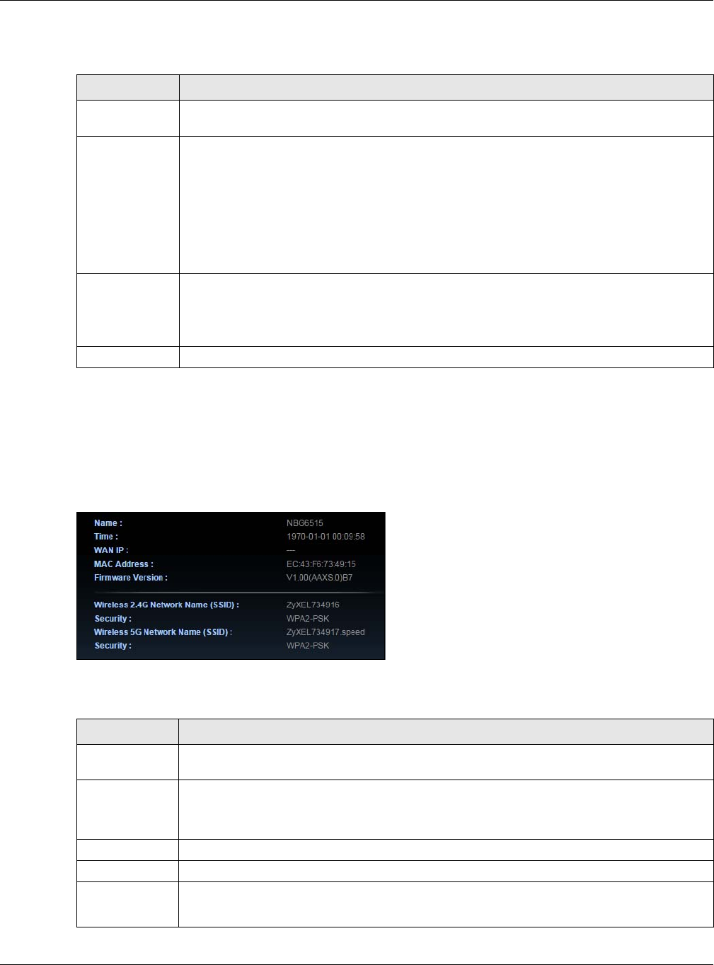
Chapter 6 Easy Mode
NBG6515 User’s Guide
48
The following table describes the labels in this screen.
6.7 Status Screen in Easy Mode
In the Network Map screen, click Status to view read-only information about the NBG.
Figure 38 Status Screen in Easy Mode
The following table describes the labels in this screen.
Table 23 Wireless Security: WPS
LABEL DESCRIPTION
Wireless
Security
Click this to go back to the Wireless Security screen.
WPS Create a secure wireless network simply by pressing a button.
The NBG scans for a WPS-enabled device within the range and performs wireless security
information synchronization.
Note: After you click the WPS button on this screen, you have to press a similar button in the
wireless station utility within 2 minutes. To add the second wireless station, you have
to press these buttons on both device and the wireless station again after the first 2
minutes.
Register Create a secure wireless network simply by entering a wireless client's PIN (Personal
Identification Number) in the NBG’s interface and pushing this button.
Type the same PIN number generated in the wireless station’s utility. Then click Register to
associate to each other and perform the wireless security information synchronization.
Exit Click Exit to close this screen.
Table 24 Status Screen in Easy Mode
ITEM DESCRIPTION
Name This is the name of the NBG in the network. You can change this in the Maintenance >
General screen in Section 25.3 on page 160.
Time This is the current system date and time.
The date is in YYYY:MM:DD (Year-Month-Day) format. The time is in HH:MM:SS
(Hour:Minutes:Seconds) format.
WAN IP This is the IP address of the WAN port.
MAC Address This is the MAC address of the NBG.
Firmware
Version
This shows the firmware version of the NBG.
The firmware version format shows the trunk version, model code and release number.

Chapter 6 Easy Mode
NBG6515 User’s Guide
49
Wireless 2.4G
Network Name
(SSID)
This shows the SSID of the wireless 2.4G network. You can configure this in the Wireless
Security screen (Section 6.6.6 on page 46; Section 11.3.1.1 on page 81).
Security This shows the wireless security used by the NBG for the 2.4G wireless radio.
Wireless 5G
Network Name
(SSID)
This shows the SSID of the wireless 5G network. You can configure this in the Wireless
Security screen (Section 6.6.6 on page 46; Section 11.3.1.1 on page 81).
Security This shows the wireless security used by the NBG for the 5G wireless radio.
Table 24 Status Screen in Easy Mode (continued)
ITEM DESCRIPTION
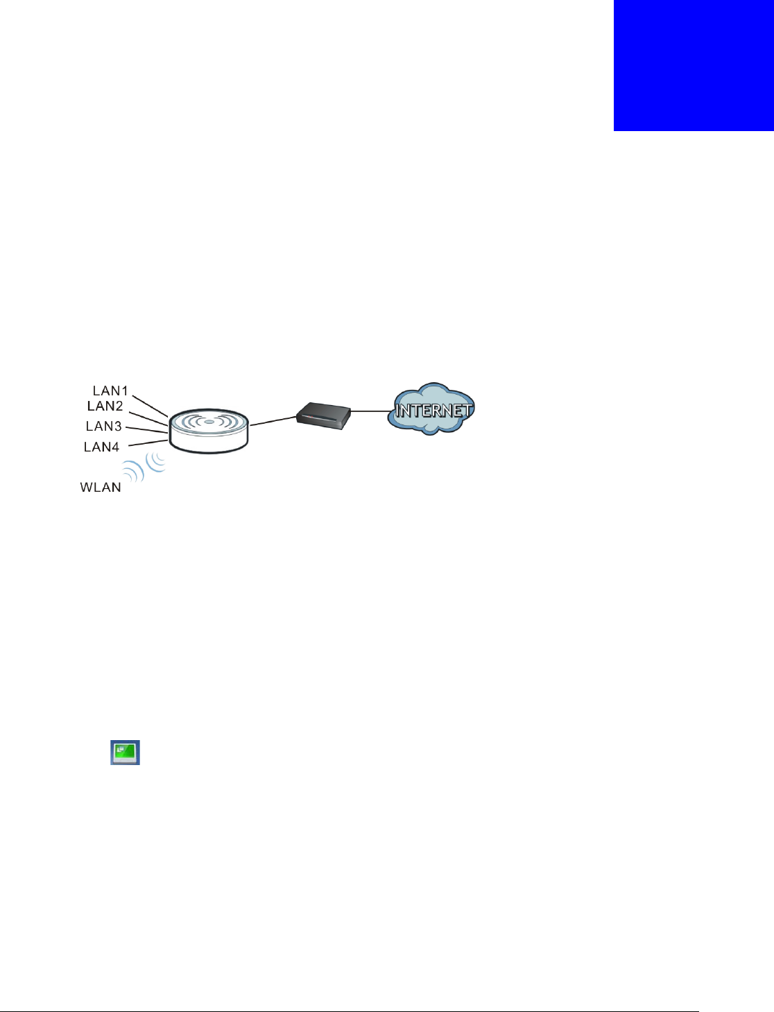
NBG6515 User’s Guide
50
CHAPTER 7
Router Mode
7.1 Overview
The NBG is set to router mode by default. Routers are used to connect the local network to another
network (for example, the Internet). In the figure below, the NBG connects the local network
(LAN1 ~ LAN4) to the Internet.
Figure 39 NBG Network
Note: The Status screen is shown after changing to the Expert mode of the Web
Configurator. It varies depending on the device mode of your NBG.
7.2 What You Can Do
Use the Status screen (Section 7.3 on page 50) to view read-only information about your NBG.
7.3 Status Screen
Click to open the status screen.
Modem
Router
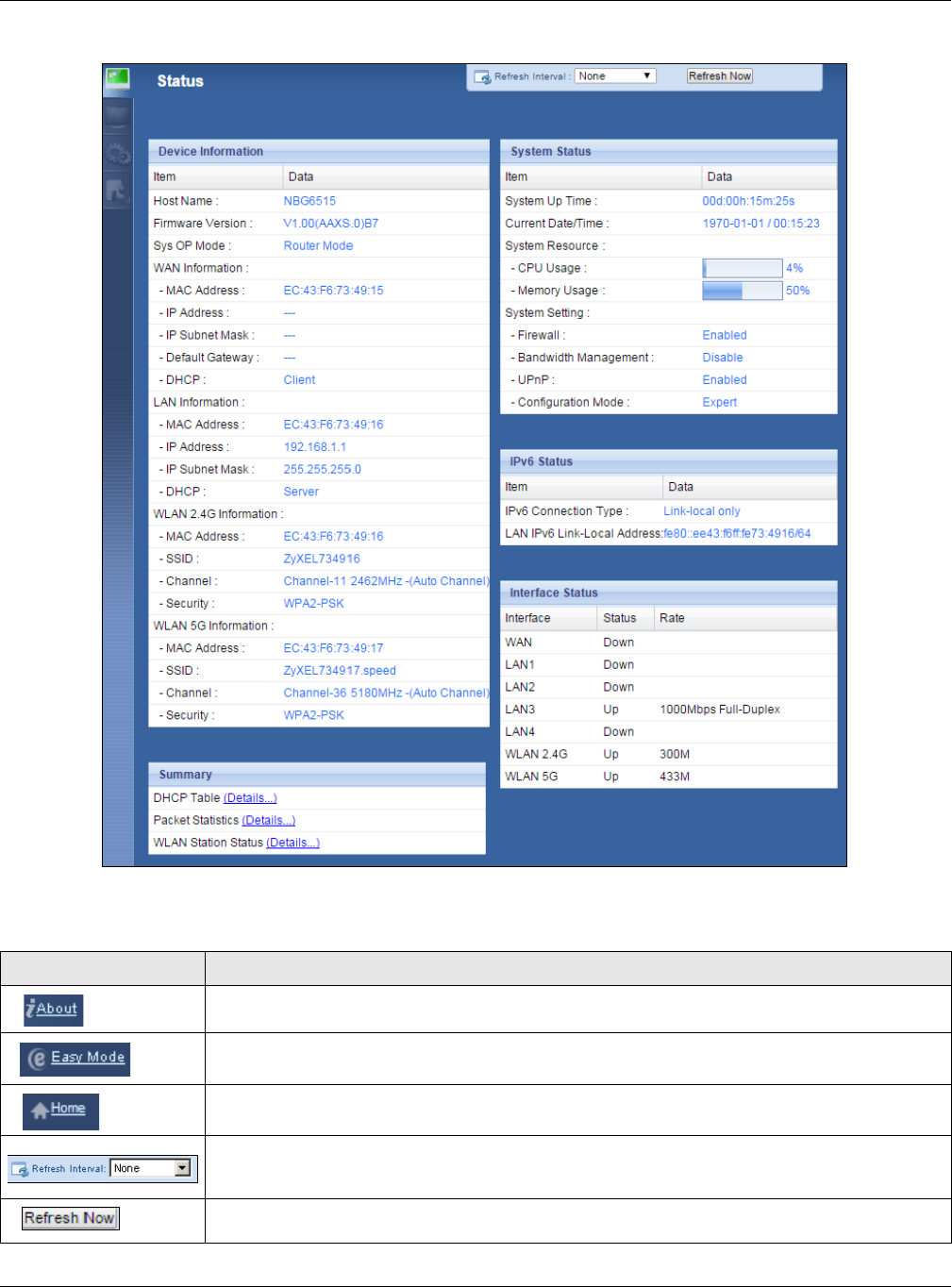
Chapter 7 Router Mode
NBG6515 User’s Guide
51
Figure 40 Status Screen: Router Mode
The following table describes the icons shown in the Status screen.
Table 25 Status Screen Icon Key: Router Mode
ICON DESCRIPTION
Click this icon to view copyright and a link for related product information.
Click this icon to go to Easy Mode. See Chapter 6 on page 38.
Click this to go to the Home page. See Chapter 4 on page 31.
Select a number of seconds or None from the drop-down list box to refresh all screen statistics
automatically at the end of every time interval or to not refresh the screen statistics.
Click this button to refresh the status screen statistics.
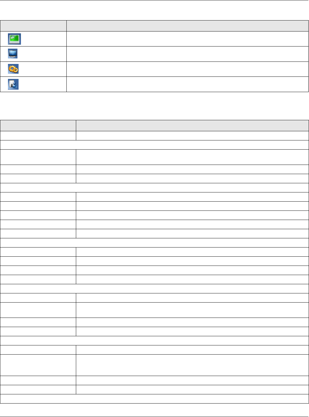
Chapter 7 Router Mode
NBG6515 User’s Guide
52
The following table describes the labels shown in the Status screen.
Click this icon to see the Status page. The information in this screen depends on the device
mode you select.
Click this icon to see the Monitor navigation menu.
Click this icon to see the Configuration navigation menu.
Click this icon to see the Maintenance navigation menu.
Table 25 Status Screen Icon Key: Router Mode (continued)
ICON DESCRIPTION
Table 26 Status Screen: Router Mode
LABEL DESCRIPTION
Logout Click this at any time to exit the Web Configurator.
Device Information
Host Name This is the System Name you enter in the Maintenance > General screen. It is for
identification purposes.
Firmware Version This is the firmware version and the date created.
Sys OP Mode This is the device mode (Section 5.1.2 on page 36) to which the NBG is set - Router Mode.
WAN Information
- MAC Address This shows the WAN Ethernet adapter MAC Address of your device.
- IP Address This shows the WAN port’s IP address.
- IP Subnet Mask This shows the WAN port’s subnet mask.
- Default Gateway This shows the WAN port’s gateway IP address.
- DHCP This shows the LAN port’s DHCP role - Client or Server.
LAN Information
- MAC Address This shows the LAN Ethernet adapter MAC Address of your device.
- IP Address This shows the LAN port’s IP address.
- IP Subnet Mask This shows the LAN port’s subnet mask.
- DHCP This shows the LAN port’s DHCP role - Server or None.
WLAN 2.4G Information
- MAC Address This shows the wireless adapter MAC Address of your device.
- SSID This shows a descriptive name used to identify the NBG in the wireless LAN. The default
SSID is ZyXEL and the last 6 digits of the 2.4G MAC address (for example, ZyXEL734916).
- Channel This shows the channel number which the NBG is currently using over the wireless LAN.
- Security This shows the level of wireless security the NBG is using.
WLAN 5G Information
- MAC Address This shows the wireless adapter MAC Address of your device.
- SSID This shows a descriptive name used to identify the NBG in the wireless LAN. The default
SSID is ZyXEL, the last 6 digits of the 5G MAC address, and .speed (for example,
ZyXEL734917.speed).
- Channel This shows the channel number which the NBG is currently using over the wireless LAN.
- Security This shows the level of wireless security the NBG is using.
System Status

Chapter 7 Router Mode
NBG6515 User’s Guide
53
7.3.1 Navigation Panel
Use the sub-menus on the navigation panel to configure NBG features.
Item This column shows the type of data the NBG is recording.
Data This column shows the actual data recorded by the NBG.
System Up Time This is the total time the NBG has been on.
Current Date/Time This field displays your NBG’s present date and time.
System Resource
- CPU Usage This displays what percentage of the NBG’s processing ability is currently used. When this
percentage is close to 100%, the NBG is running at full load, and the throughput is not going
to improve anymore. If you want some applications to have more throughput, you should
turn off other applications (for example, using bandwidth management.)
- Memory Usage This shows what percentage of the heap memory the NBG is using.
System Setting
- Firewall This shows whether the firewall is enabled or not.
- Bandwidth
Management This shows whether the bandwidth management is enabled or not.
- UPnP This shows whether UPnP is enabled or not.
- Configuration Mode This shows the web configurator mode you are viewing - Expert.
IPv6 Status
Item This column shows the type of data the IPv6 is using.
Data This column shows the actual data used through the IPv6.
Interface Status
Interface This displays the NBG port types. The port types are: WAN, LAN and WLAN.
Status For the LAN and WAN ports, this field displays Down (line is down) or Up (line is up or
connected).
For the WLAN, it displays Up when the WLAN is enabled or Down when the WLAN is
disabled.
Rate For the LAN ports, this displays the port speed and duplex setting or N/A when the line is
disconnected.
For the WAN port, it displays the port speed and duplex setting if you’re using Ethernet
encapsulation and Idle (line (ppp) idle), Dial (starting to trigger a call) and Drop (dropping
a call) if you're using PPPoE or PPTP encapsulation. This field displays N/A when the line is
disconnected.
For the WLAN, it displays the maximum transmission rate when the WLAN is enabled and N/
A when the WLAN is disabled.
Summary
DHCP Table Click Details... to go to the Monitor > DHCP Table screen (Section 4.4 on page 32). Use
this screen to view current DHCP client information.
Packet Statistics Click Details... to go to the Monitor > Packet Statistics screen (Section 4.5 on page 33).
Use this screen to view port status and packet specific statistics.
WLAN Station Status Click Details... to go to the Monitor > WLAN 2.4G / 5G Station Status screen (Section
4.7 on page 35). Use this screen to view the wireless stations that are currently associated
to the NBG.
Table 26 Status Screen: Router Mode (continued)
LABEL DESCRIPTION
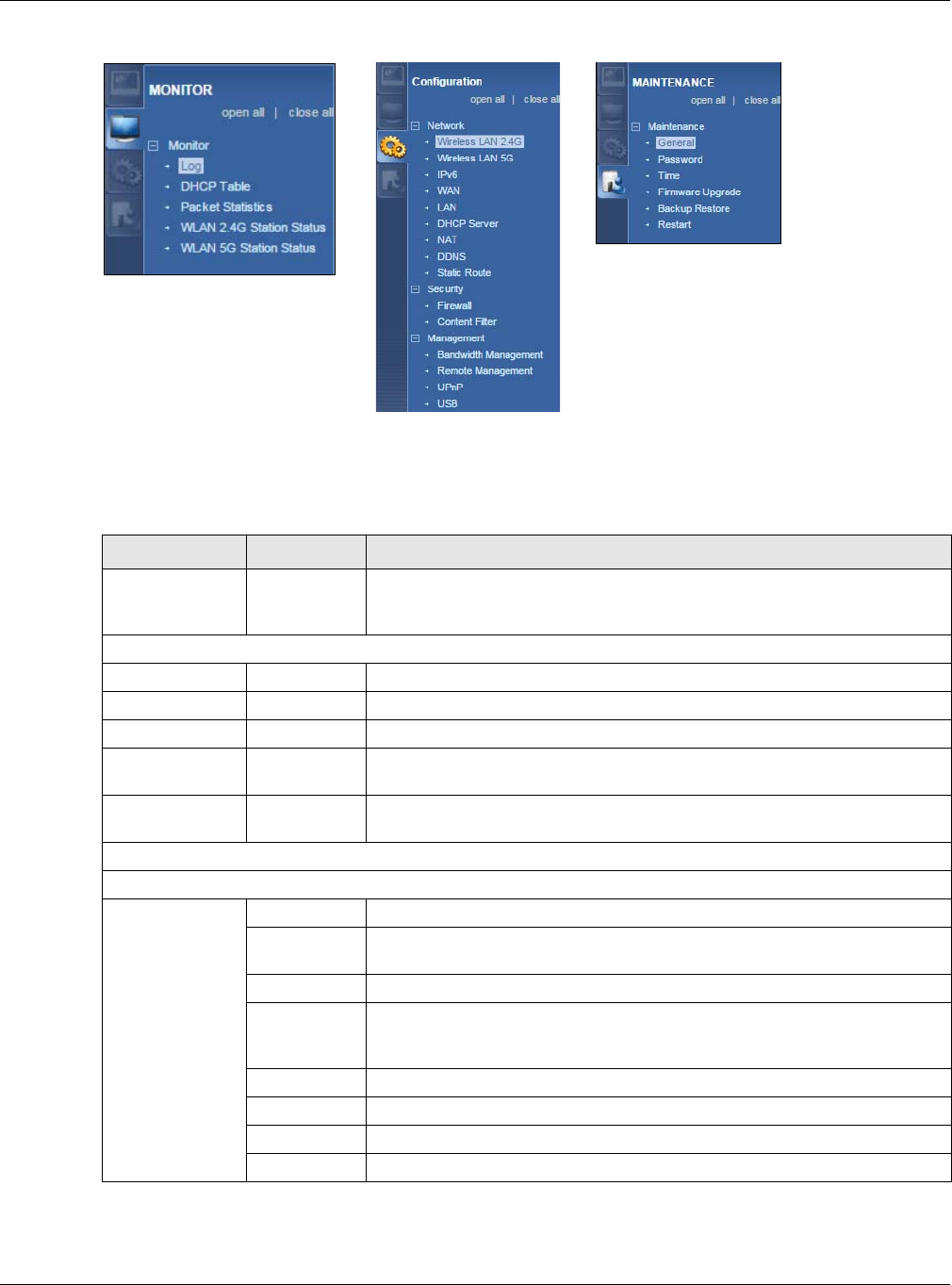
Chapter 7 Router Mode
NBG6515 User’s Guide
54
Figure 41 Navigation Panel: Router Mode
The following table describes the sub-menus.
Table 27 Navigation Panel: Router Mode
LINK TAB FUNCTION
Status This screen shows the NBG’s general device, system and interface status
information. Use this screen to access the wizard, and summary statistics
tables.
MONITOR
Log Use this screen to view the list of activities recorded by your NBG.
DHCP Table Use this screen to view current DHCP client information.
Packet Statistics Use this screen to view port status and packet specific statistics.
WLAN 2.4G
Station Status
Use this screen to view the wireless stations that are currently associated
to the NBG through the wireless 2.4G network.
WLAN 5G
Station Status
Use this screen to view the wireless stations that are currently associated
to the NBG through the wireless 5G network.
CONFIGURATION
Network
Wireless LAN
2.4G General Use this screen to configure wireless 2.4G LAN.
MAC Filter Use the MAC filter screen to configure the NBG to block access to devices
or block the devices from accessing the NBG.
Advanced This screen allows you to configure advanced wireless settings.
QoS Use this screen to configure Wi-Fi Multimedia Quality of Service (WMM
QoS). WMM QoS allows you to prioritize wireless traffic according to the
delivery requirements of individual services.
WPS Use this screen to configure WPS.
WPS Device Use this screen to add a wireless station using WPS.
Scheduling Use this screen to schedule the times the Wireless LAN is enabled.
Guest WLAN Use this screen to configure multiple BSSs on the NBG.

Chapter 7 Router Mode
NBG6515 User’s Guide
55
Wireless LAN
5G General Use this screen to configure wireless 5G LAN.
MAC Filter Use the MAC filter screen to configure the NBG to block access to devices
or block the devices from accessing the NBG.
Advanced This screen allows you to configure advanced wireless settings.
QoS Use this screen to configure Wi-Fi Multimedia Quality of Service (WMM
QoS). WMM QoS allows you to prioritize wireless traffic according to the
delivery requirements of individual services.
WPS Use this screen to configure WPS.
WPS Device Use this screen to add a wireless station using WPS.
Scheduling Use this screen to schedule the times the Wireless LAN is enabled.
Guest WLAN Use this screen to configure multiple BSSs on the NBG.
IPv6 General Use this screen to configure the IPv6 connection type.
WAN Internet
Connection
This screen allows you to configure ISP parameters, WAN IP address
assignment, DNS servers and the WAN MAC address.
Advanced Use this screen to configure other advanced properties.
LAN IP Use this screen to configure LAN IP address and subnet mask.
DHCP Server General Use this screen to enable the NBG’s DHCP server.
Advanced Use this screen to assign IP addresses to specific individual computers
based on their MAC addresses and to have DNS servers assigned by the
DHCP server.
NAT General Use this screen to enable NAT.
Application Use this screen to configure servers behind the NBG.
Advanced Use this screen to change your NBG’s port triggering settings.
DDNS General Use this screen to set up dynamic DNS.
Static Route IP Static
Route
Use this screen to configure IP static routes.
Security
Firewall General Use this screen to activate/deactivate the firewall.
MAC Filtering
Rule
Use the MAC filtering rule screen to configure the NBG to block access to
devices or block the devices from accessing the NBG.
IP Filtering
Rule
Use the IP filtering rule screen to configure the NBG to block access to
devices or block the devices from accessing the NBG.
Content
Filter Use this screen to block certain web features and sites containing certain
keywords in the URL.
Management
Bandwidth
Management General Use this screen to enable bandwidth management.
Advanced Use this screen to set the upstream bandwidth and edit a bandwidth
management rule.
Remote
Management WWW Use this screen to be able to access the NBG from the LAN, WAN or both.
UPnP General Use this screen to enable UPnP on the NBG.
USB SMB/CIFS Use this screen to enable file sharing through the NBG.
DLNA Use this screen to have the NBG function as a DLNA-compliant media
server, that lets DLNA-compliant media clients play video, audio, and photo
content files stored on the connected USB storage device.
FTP Use this screen to have the NBG act as a FTP server.
Table 27 Navigation Panel: Router Mode (continued)
LINK TAB FUNCTION

Chapter 7 Router Mode
NBG6515 User’s Guide
56
MAINTENANCE
General Use this screen to view and change administrative settings such as system
and domain names.
Password Password
Setup
Use this screen to change the password of your NBG.
Time Time Setting Use this screen to change your NBG’s time and date.
Firmware
Upgrade Use this screen to upload firmware to your NBG.
Backup
Restore Use this screen to backup and restore the configuration or reset the factory
defaults to your NBG.
Restart This screen allows you to reboot the NBG without turning the power off.
Table 27 Navigation Panel: Router Mode (continued)
LINK TAB FUNCTION
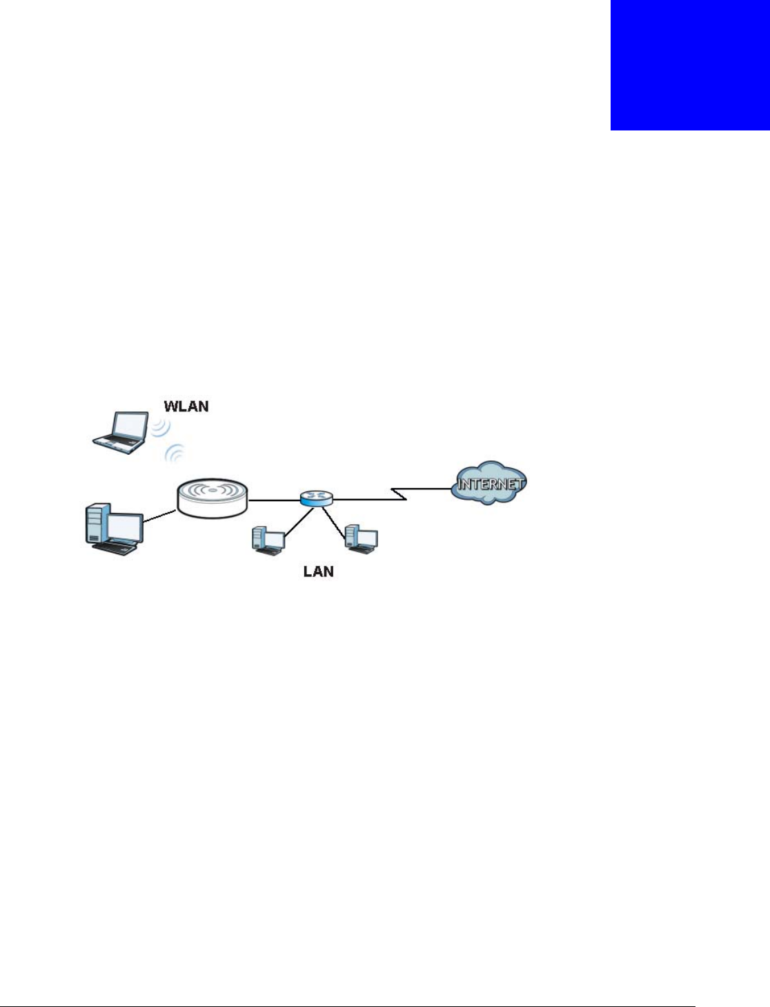
NBG6515 User’s Guide
57
CHAPTER 8
Access Point Mode
8.1 Overview
Use your NBG as an access point (AP) if you already have a router or gateway on your network. In
this mode your NBG bridges a wired network (LAN) and wireless LAN (WLAN) in the same subnet.
See the figure below for an example.
Figure 42 Wireless Internet Access in Access Point Mode
Many screens that are available in Router mode are not available in Access Point mode, such as
bandwidth management and firewall.
Note: See Chapter 10 on page 72 for an example of setting up a wireless network in
Access Point mode.
8.2 What You Can Do
•Use the Status screen (Section 8.4 on page 58) to view read-only information about your NBG.
•Use the LAN screen (Section 8.5 on page 61) to set the IP address for your NBG acting as an
access point.
8.3 What You Need to Know
See Chapter 10 on page 72 for a tutorial on setting up a network with the NBG as an access point.
Router

Chapter 8 Access Point Mode
NBG6515 User’s Guide
58
8.3.1 Setting your NBG to AP Mode
1Log into the Web Configurator if you haven’t already. See the Quick start Guide for instructions on
how to do this.
2To use your NBG as an access point, switch the physical button which placed at the bottom of the
NBG to the middle place.
Note: You have to log in to the Web Configurator again when you change modes. As soon
as you do, your NBG is already in Access Point mode.
3The Web Configurator refreshes once the change to Access Point mode is successful.
8.3.2 Accessing the Web Configurator in Access Point Mode
Log in to the Web Configurator in Access Point mode, do the following:
1Connect your computer to the LAN port of the NBG.
2The default IP address of the NBG is “192.168.1.2”. In this case, your computer must have an IP
address in the range between “192.168.1.3” and “192.168.1.254”.
3Click Start > Run on your computer in Windows. Type “cmd” in the dialog box. Enter “ipconfig” to
show your computer’s IP address. If your computer’s IP address is not in the correct range then see
Appendix C on page 191 for information on changing your computer’s IP address.
4After you’ve set your computer’s IP address, open a web browser such as Internet Explorer and
type “192.168.1.2” as the web address in your web browser.
Note: After clicking Login, the Easy mode appears. Refer to page 38 for the Easy mode
screens. Change to Expert mode to see the screens described in the sections
following this.
8.3.3 Configuring your WLAN, Bandwidth Management and Maintenance
Settings
The configuration of wireless, bandwidth management and maintenance settings in Access Point
mode is the same as for Router Mode.
•See Chapter 11 on page 80 for information on the configuring your wireless network.
•See Chapter 21 on page 136 for information on configuring your Bandwidth Management screen.
•See Chapter 25 on page 160 to Chapter 25 on page 160 for information on configuring your
Maintenance settings.
8.4 AP Mode Status Screen
Click to open the Status screen.
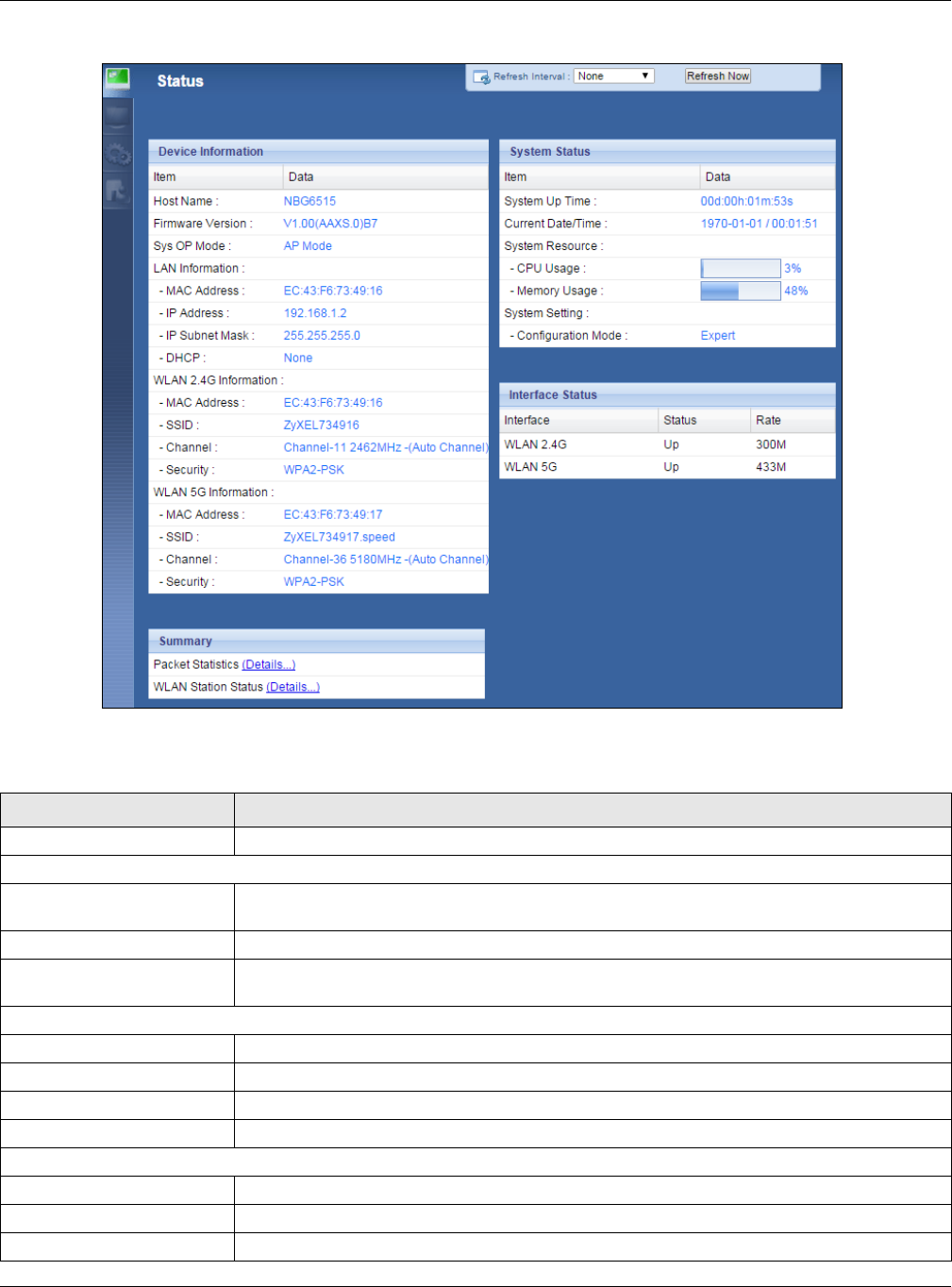
Chapter 8 Access Point Mode
NBG6515 User’s Guide
59
Figure 43 Status Screen: Access Point Mode
The following table describes the labels shown in the Status screen.
Table 28 Status Screen: Access Point Mode
LABEL DESCRIPTION
Logout Click this at any time to exit the Web Configurator.
Device Information
Host Name This is the System Name you enter in the Maintenance > General screen. It is for
identification purposes.
Firmware Version This is the firmware version and the date created.
Sys OP Mode This is the device mode (Section 5.1.2 on page 36) to which the NBG is set - Access Point
Mode.
LAN Information
- MAC Address This shows the LAN Ethernet adapter MAC Address of your device.
- IP Address This shows the LAN port’s IP address.
- IP Subnet Mask This shows the LAN port’s subnet mask.
- DHCP This shows the LAN port’s DHCP role - Server, Client or None.
WLAN 2.4G Information
- MAC Address This shows the wireless adapter MAC Address of your device.
- SSID This shows a descriptive name used to identify the NBG in the wireless 2.4G LAN.
- Channel This shows the channel number which you select manually.

Chapter 8 Access Point Mode
NBG6515 User’s Guide
60
8.4.0.1 Navigation Panel
Use the menu in the navigation panel to configure NBG features in Access Point mode.
The following screen and table show the features you can configure in Access Point mode.
- Security This shows the level of wireless security the NBG is using.
WLAN 5G Information
- MAC Address This shows the wireless adapter MAC Address of your device.
- SSID This shows a descriptive name used to identify the NBG in the wireless 5G LAN.
- Channel This shows the channel number which you select manually.
- Security This shows the level of wireless security the NBG is using.
System Status
Item This column shows the type of data the NBG is recording.
Data This column shows the actual data recorded by the NBG.
System Up Time This is the total time the NBG has been on.
Current Date/Time This field displays your NBG’s present date and time.
System Resource
- CPU Usage This displays what percentage of the NBG’s processing ability is currently used. When this
percentage is close to 100%, the NBG is running at full load, and the throughput is not going
to improve anymore. If you want some applications to have more throughput, you should
turn off other applications (for example, using bandwidth management.
- Memory Usage This shows what percentage of the heap memory the NBG is using.
System Setting
- Configuration Mode This shows the web configurator mode you are viewing - Expert.
Interface Status
Interface This displays the NBG port types. The port types are: LAN, WLAN 2.4G, and WLAN 5G.
Status For the LAN and WAN ports, this field displays Down (line is down) or Up (line is up or
connected).
For the WLAN, it displays Up when the WLAN is enabled or Down when the WLAN is
disabled.
Rate For the LAN ports, this displays the port speed and duplex setting or N/A when the line is
disconnected.
For the WAN port, it displays the port speed and duplex setting if you’re using Ethernet
encapsulation and Idle (line (ppp) idle), Dial (starting to trigger a call) and Drop (dropping
a call) if you're using PPPoE or PPTP encapsulation. This field displays N/A when the line is
disconnected.
For the WLAN, it displays the maximum transmission rate when the WLAN is enabled and N/
A when the WLAN is disabled.
Summary
Packet Statistics Click Details... to go to the Monitor > Packet Statistics screen (Section 4.5 on page 33).
Use this screen to view port status and packet specific statistics.
WLAN Station Status Click Details... to go to the Monitor > WLAN 2.4G / 5G Station Status screen (Section
4.7 on page 35). Use this screen to view the wireless stations that are currently associated
to the NBG.
Table 28 Status Screen: Access Point Mode (continued)
LABEL DESCRIPTION
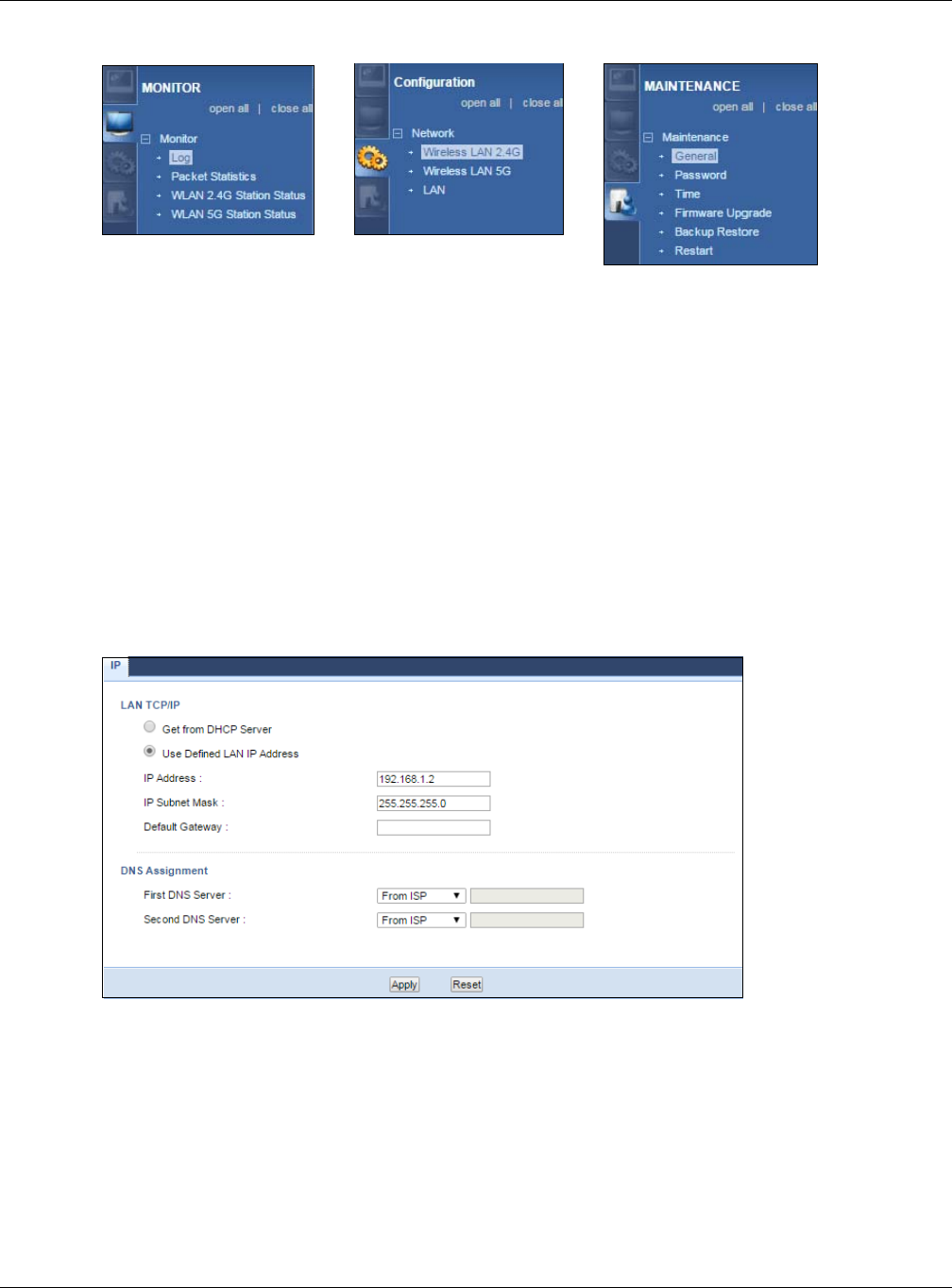
Chapter 8 Access Point Mode
NBG6515 User’s Guide
61
Figure 44 Menu: Access Point Mode
Refer to Table 27 on page 54 for descriptions of the labels shown in the Navigation panel.
8.5 LAN Screen
Use this section to configure your LAN settings while in Access Point mode.
Click Network > LAN to see the screen below.
Note: If you change the IP address of the NBG in the screen below, you will need to log
into the NBG again using the new IP address.
Figure 45 Network > LAN > IP
The table below describes the labels in the screen.

Chapter 8 Access Point Mode
NBG6515 User’s Guide
62
Table 29 Network > LAN > IP
LABEL DESCRIPTION
Get from DHCP
Server
Click this to deploy the NBG as an access point in the network.
When you enable this, the NBG gets its IP address from the network’s DHCP server (for
example, your ISP). Users connected to the NBG can now access the network (i.e., the
Internet if the IP address is given by the ISP).
The Web Configurator may no longer be accessible unless you know the IP address assigned
by the DHCP server to the NBG. You need to reset the NBG to be able to access the Web
Configurator again (see Section 25.7 on page 164 for details on how to reset the NBG).
Also when you select this, you cannot enter an IP address for your NBG in the field below.
Use Defined
LAN IP Address
Click this if you want to specify the IP address of your NBG. Or if your ISP or network
administrator gave you a static IP address to access the network or the Internet.
IP Address Type the IP address in dotted decimal notation. The default setting is 192.168.1.2. If you
change the IP address you will have to log in again with the new IP address.
IP Subnet Mask The subnet mask specifies the network number portion of an IP address. Your NBG will
automatically calculate the subnet mask based on the IP address that you assign. Unless
you are implementing subnetting, use the subnet mask computed by the NBG.
Default
Gateway
Enter a Default Gateway IP Address (if your ISP or network administrator gave you one) in
this field.
DNS Assignment
First DNS
Server
Second DNS
Server
Select From ISP if your ISP dynamically assigns DNS server information (and the NBG's
WAN IP address). The field to the right displays the (read-only) DNS server IP address that
the ISP assigns.
Select User-Defined if you have the IP address of a DNS server. Enter the DNS server's IP
address in the field to the right. If you chose User-Defined, but leave the IP address set to
0.0.0.0, User-Defined changes to None after you click Apply. If you set a second choice to
User-Defined, and enter the same IP address, the second User-Defined changes to None
after you click Apply.
Select None if you do not want to configure DNS servers. If you do not configure a DNS
server, you must know the IP address of a computer in order to access it.
Apply Click Apply to save your changes to the NBG.
Reset Click Reset to reload the previous configuration for this screen.
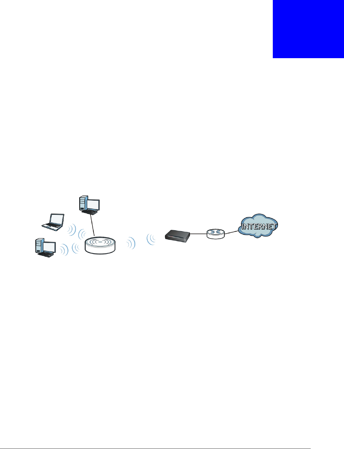
NBG6515 User’s Guide
63
CHAPTER 9
Universal Repeater Mode
9.1 Overview
In universal repeater mode, your NBG can act as an access point and wireless client at the same
time. The NBG can connect to an existing network through another access point and also lets
wireless clients connect to the network through it. This helps you expand wireless coverage when
you have an access point or wireless router already in your network.
In the example below, the NBG (A) is configured as a universal repeater. It has three clients that
want to connect to the Internet. The NBG wirelessly connects to the available access point (B).
Figure 46 Universal Repeater Mode
After the NBG and the access point connect, the NBG acquires its IP address from the access point.
The clients of the NBG can now surf the Internet.
9.2 What You Can Do
•Use the Status screen to view read-only information about your NBG (Section 9.5 on page 64).
•Use the AP Select screen to choose an access point that you want the NBG to connect to. You
should know the security settings of the target AP (Section 9.6 on page 67).
•Use other Wireless LAN screens to configure the wireless settings and wireless security
between the wireless clients and the NBG.
•Use the LAN screen to set the IP address for your NBG acting as an access point (Section 8.5 on
page 61).
9.3 What You Need to Know
With the exception of the Network > Wireless LAN 2.4G/5G > AP Select screens, other
configuration screens in Universal Repeater Mode are similar to the ones in Access Point Mode.
AB

Chapter 9 Universal Repeater Mode
NBG6515 User’s Guide
64
See Chapter 11 on page 80 through switching the physical button which placed at the bottom of the
NBG of this User’s Guide.
9.4 Setting your NBG to Universal Repeater Mode
1Connect your computer to the LAN port of the NBG.
2The default IP address of the NBG is “192.168.1.2”. In this case, your computer must have an IP
address in the range between “192.168.1.3” and “192.168.1.254”.
3Click Start > Run on your computer in Windows. Type “cmd” in the dialog box. Enter “ipconfig” to
show your computer’s IP address. If your computer’s IP address is not in the correct range then see
Appendix C on page 251 for information on changing your computer’s IP address.
4After you’ve set your computer’s IP address, open a web browser such as Internet Explorer and
type “http://192.168.1.2” as the web address in your web browser.
5Enter “1234” (default) as the password and click Login.
6Type a new password and retype it to confirm, then click Apply. Otherwise, click Ignore.
7The Easy mode appears. Click Expert Mode in the navigation panel.
8To set your NBG to Universal Repeater Mode, switch the physical button which placed at the
bottom of the NBG to the right side.
9You have to log in to the Web Configurator again when you change modes. As soon as you do, your
NBG is already in Universal Repeater mode.
The Web Configurator refreshes once the change to Universal Repeater mode is successful.
9.5 Universal Repeater Mode Status Screen
Click to open the status screen.
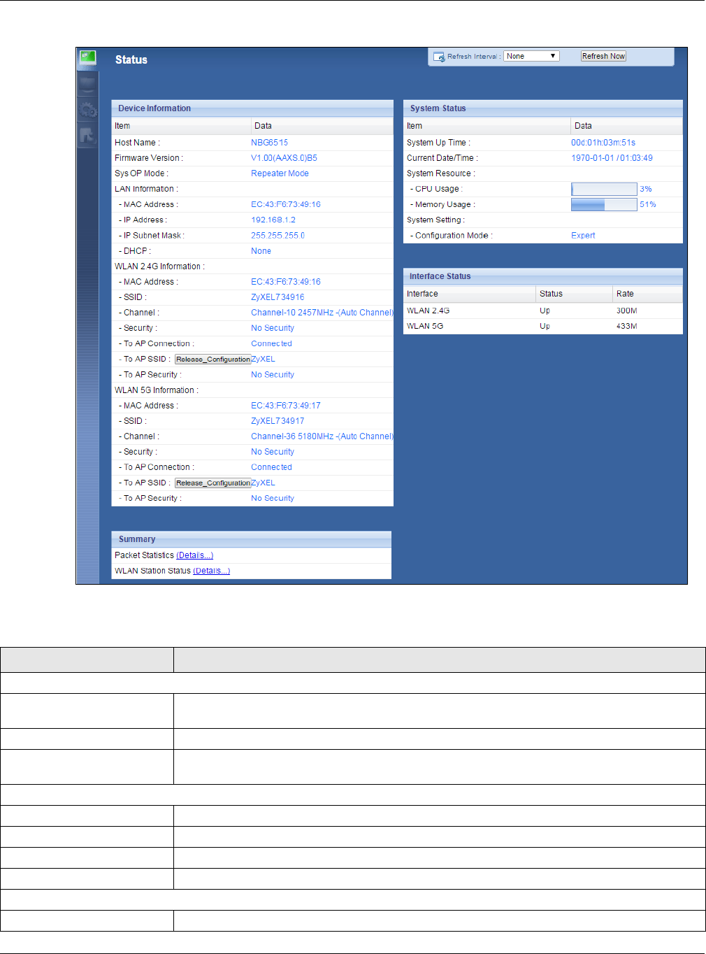
Chapter 9 Universal Repeater Mode
NBG6515 User’s Guide
65
Figure 47 Status: Universal Repeater Mode
The following table describes the labels shown in the Status screen.
Table 30 Status Screen: Universal Repeater Mode
LABEL DESCRIPTION
Device Information
Host Name This is the System Name you enter in the Maintenance > General screen. It is for
identification purposes.
Firmware Version This is the firmware version and the date created.
Sys OP Mode This is the device mode (Section 5.1.2 on page 36) to which the NBG is set - Universal
Repeater Mode.
LAN Information
- MAC Address This shows the LAN Ethernet adapter MAC Address of your device.
- IP Address This shows the LAN port’s IP address.
- IP Subnet Mask This shows the LAN port’s subnet mask.
- DHCP This shows the LAN port’s DHCP role - Client or None.
WLAN 2.4G Information
- MAC Address This shows the wireless adapter MAC Address of your device.

Chapter 9 Universal Repeater Mode
NBG6515 User’s Guide
66
- SSID This shows a descriptive name used to identify the NBG in the wireless LAN.
- Channel This shows the channel number which you select manually.
- Security This shows the level of wireless security the NBG is using.
- To AP Connection This shows the WLAN station status. If the NBG has successfully connected to an AP or
wireless router, it displays Connected. Otherwise, it displays Disconnected.
- To AP SSID This shows the SSID of the AP or wireless router.
Release_Configuration This button is only available when the NBG has successfully connected to an AP or wireless
router.
Click this button to remove all configured wireless connections and wireless security settings
on the NBG.
- To AP Security This shows the security mode of the AP or wireless router is using.
WLAN 5G Information
- MAC Address This shows the wireless adapter MAC Address of your device.
- SSID This shows a descriptive name used to identify the NBG in the wireless LAN.
- Channel This shows the channel number which you select manually.
- Security This shows the level of wireless security the NBG is using.
- To AP Connection This shows the WLAN station status. If the NBG has successfully connected to an AP or
wireless router, it displays Connected. Otherwise, it displays Disconnected.
- To AP SSID This shows the SSID of the AP or wireless router.
Release_Configuration This button is only available when the NBG has successfully connected to an AP or wireless
router.
Click this button to remove all configured wireless connections and wireless security settings
on the NBG.
- To AP Security This shows the security mode of the AP or wireless router is using.
Summary
Packet Statistics Click Details... to go to the Monitor > Packet Statistics screen (Section 4.5 on page 33).
Use this screen to view port status and packet specific statistics.
WLAN Station Status Click Details... to go to the Monitor > WLAN Station Status screen (Section 4.7 on page
35). Use this screen to view the wireless stations that are currently associated to the NBG.
System Status
Item This column shows the type of data the NBG is recording.
Data This column shows the actual data recorded by the NBG.
System Up Time This is the total time the NBG has been on.
Current Date/Time This field displays your NBG’s present date and time.
System Resource
- CPU Usage This displays what percentage of the NBG’s processing ability is currently used. When this
percentage is close to 100%, the NBG is running at full load, and the throughput is not going
to improve anymore. If you want some applications to have more throughput, you should
turn off other applications (for example, using bandwidth management.
- Memory Usage This shows what percentage of the heap memory the NBG is using.
System Setting
- Configuration Mode This shows the web configurator mode you are viewing - Expert.
Interface Status
Interface This displays the NBG port types. The port types are: LAN and WLAN.
Table 30 Status Screen: Universal Repeater Mode (continued)
LABEL DESCRIPTION
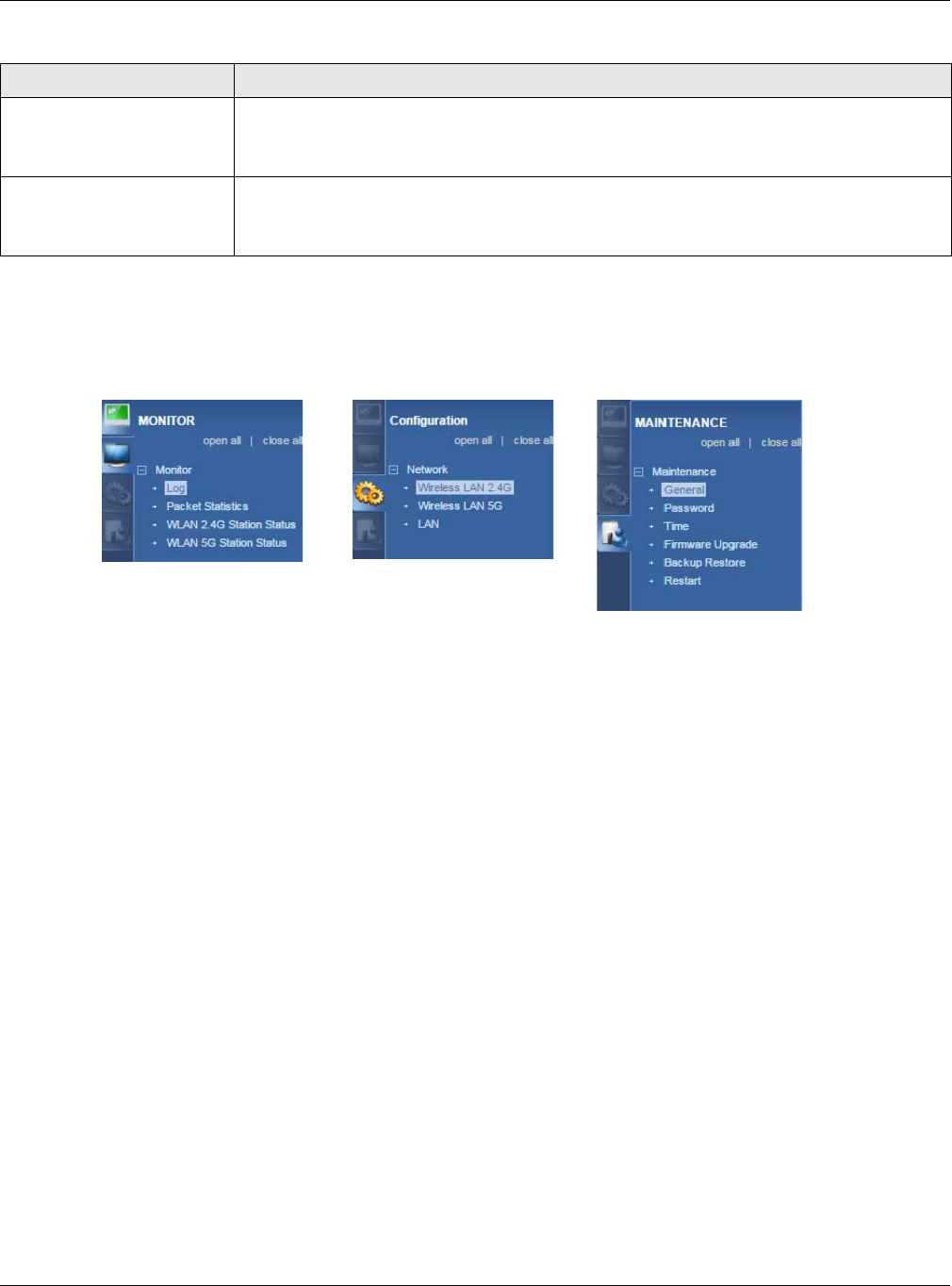
Chapter 9 Universal Repeater Mode
NBG6515 User’s Guide
67
9.5.1 Navigation Panel
Use the menu in the navigation panel to configure NBG features in Universal Repeater Mode.
Figure 48 Menu: Universal Repeater Mode
Refer to Table 27 on page 54 for descriptions of the labels shown in the navigation panel.
9.6 AP Select Screen
9.6.1 Wireless LAN 2.4G
Use this screen to choose an access point that you want the NBG to connect to. You should know
the security settings of the target AP.
To open this screen, click Network > Wireless LAN 2.4G > AP Select tab.
Status For the LAN ports, this field displays Down (line is down) or Up (line is up or connected).
For the WLAN, it displays Up when the WLAN is enabled or Down when the WLAN is
disabled.
Rate For the LAN ports, this displays the port speed or N/A when the line is disconnected.
For the WLAN, it displays the maximum transmission rate when the WLAN is enabled and N/
A when the WLAN is disabled.
Table 30 Status Screen: Universal Repeater Mode (continued)
LABEL DESCRIPTION
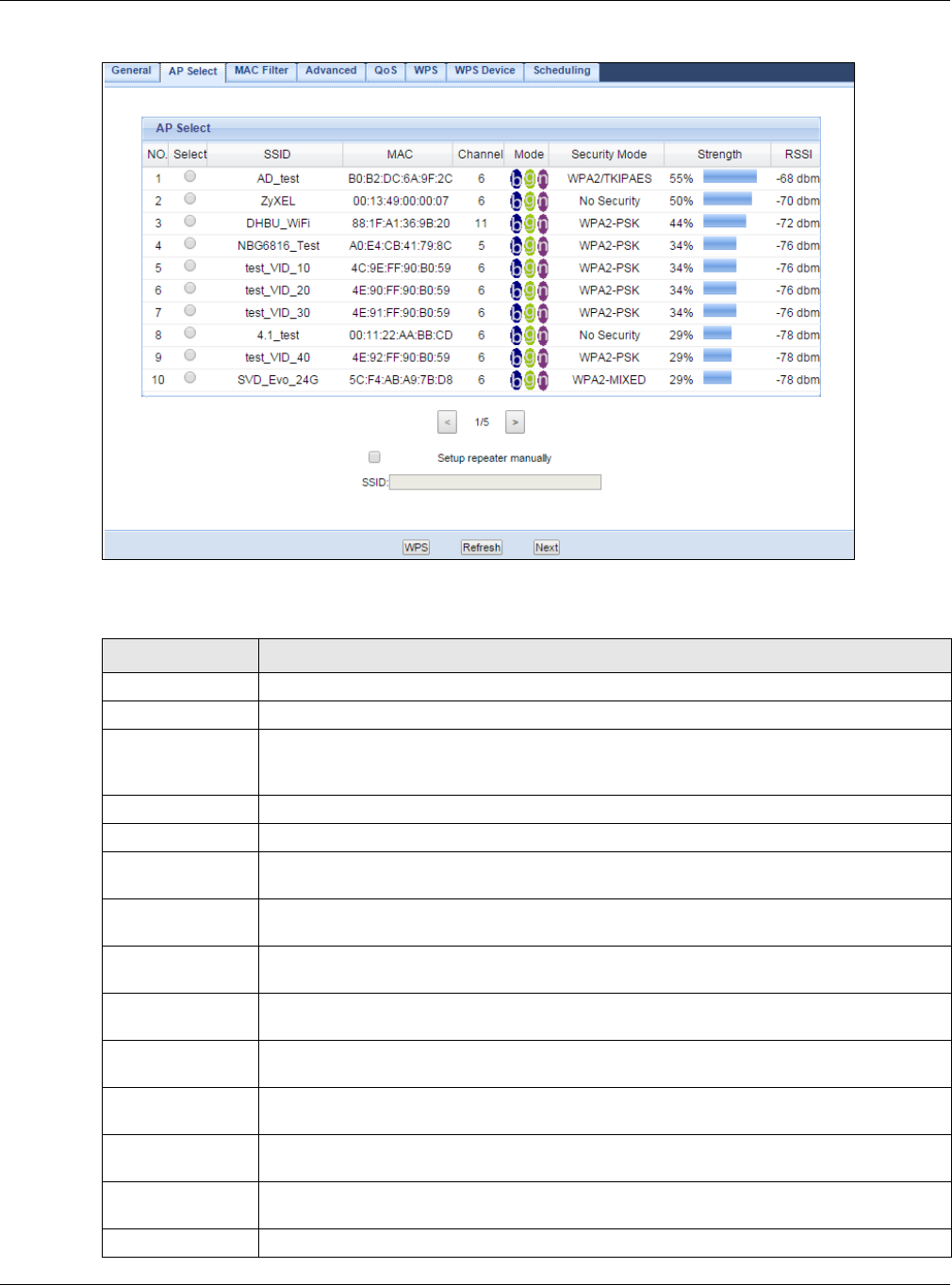
Chapter 9 Universal Repeater Mode
NBG6515 User’s Guide
68
Figure 49 Network > Wireless LAN 2.4G > AP Select
The following table describes the labels in this screen.
Table 31 Network > Wireless LAN 2.4G > AP Select
LABEL DESCRIPTION
NO. This is the index number of the APs.
Select Use the radio button to select the wireless device to which you want to connect.
SSID This displays the Service Set IDentity of the wireless device. The SSID is a unique name
that identifies a wireless network. All devices in a wireless network must use the same
SSID.
MAC This displays the MAC address of the wireless device.
Channel This displays the channel number used by this wireless device.
Mode This displays which IEEE 802.11b/g/n wireless networking standards the wireless device
supports.
Security Mode This displays the type of security configured on the wireless device. When No Security is
shown, no security is configured and you can connect to it without a password.
Strength This displays the strength of the wireless signal. The signal strength mainly depends on
the antenna output power and the distance between your NBG and this device.
RSSI This shows the received signal strength indicator (RSSI), that is, the received signal
strength in dBm.
Setup repeater
manually
Select this to setup the AP manually.
SSID If Setup repeater manually is selected, use this field to type the SSID of the AP. This is
useful when the AP’s SSID is hidden.
WPS Click WPS to start WPS-aware wireless station scanning and the wireless security
information synchronization.
Refresh Click this to search for available wireless devices within transmission range and update
this table.
Next Click this to continue.
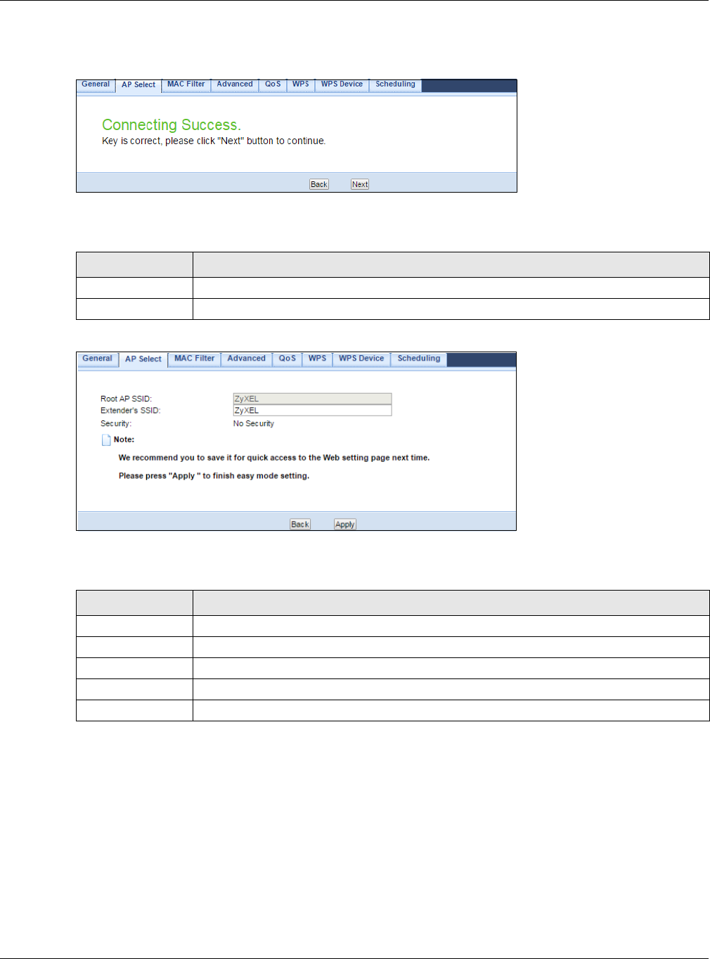
Chapter 9 Universal Repeater Mode
NBG6515 User’s Guide
69
After you selected one of APs and click the Next button, the screen will display as below.
Figure 50 Network > Wireless LAN 2.4G > AP Select: Connecting Success
The following table describes the labels in this screen.
Figure 51 Network > Wireless LAN 2.4G > AP Select: Root AP SSID
The following table describes the labels in this screen.
9.6.2 Wireless LAN 5G
Use this screen to choose an access point that you want the NBG to connect to. You should know
the security settings of the target AP.
To open this screen, click Network > Wireless LAN 5G > AP Select tab.
Table 32 Network > Wireless LAN 2.4G > AP Select: Connecting Success
LABEL DESCRIPTION
Back Click this to return to the previous screen.
Next Click this to continue.
Table 33 Network > Wireless LAN 2.4G > AP Select: Root AP SSID
LABEL DESCRIPTION
Root AP SSID This field displays the specific AP’s SSID which you used through the NBG.
Extender’s SSID This field displays the SSID of the NBG as an extender.
Security This field displays the specific AP’s security mode which you used through the NBG.
Back Click this to return to the previous screen.
Apply Click Apply to save your changes to the NBG.
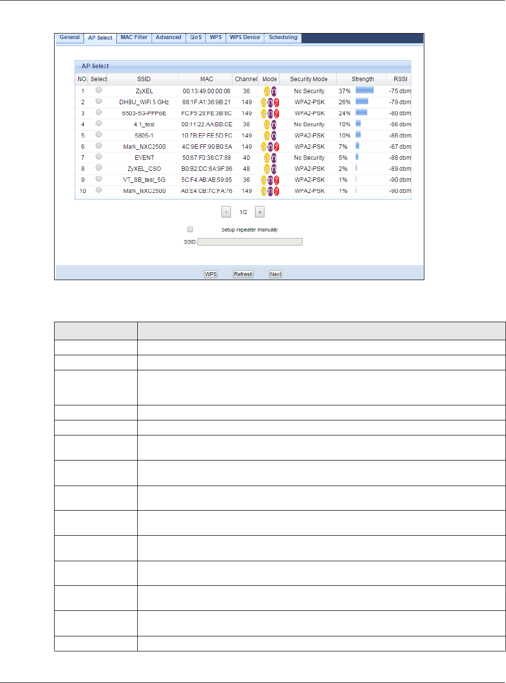
Chapter 9 Universal Repeater Mode
NBG6515 User’s Guide
70
Figure 52 Network > Wireless LAN 5G > AP Select
The following table describes the labels in this screen.
Table 34 Network > Wireless LAN 5G > AP Select
LABEL DESCRIPTION
NO. This is the index number of the APs.
Select Use the radio button to select the wireless device to which you want to connect.
SSID This displays the Service Set IDentity of the wireless device. The SSID is a unique name
that identifies a wireless network. All devices in a wireless network must use the same
SSID.
MAC This displays the MAC address of the wireless device.
Channel This displays the channel number used by this wireless device.
Mode This displays which IEEE 802.11b/g/n wireless networking standards the wireless device
supports.
Security Mode This displays the type of security configured on the wireless device. When No Security is
shown, no security is configured and you can connect to it without a password.
Strength This displays the strength of the wireless signal. The signal strength mainly depends on
the antenna output power and the distance between your NBG and this device.
RSSI This shows the received signal strength indicator (RSSI), that is, the received signal
strength in dBm.
Setup repeater
manually
Select this to setup the AP manually.
SSID If Setup repeater manually is selected, use this field to type the SSID of the AP. This is
useful when the AP’s SSID is hidden.
WPS Click WPS to start WPS-aware wireless station scanning and the wireless security
information synchronization.
Refresh Click this to search for available wireless devices within transmission range and update
this table.
Next Click this to continue.
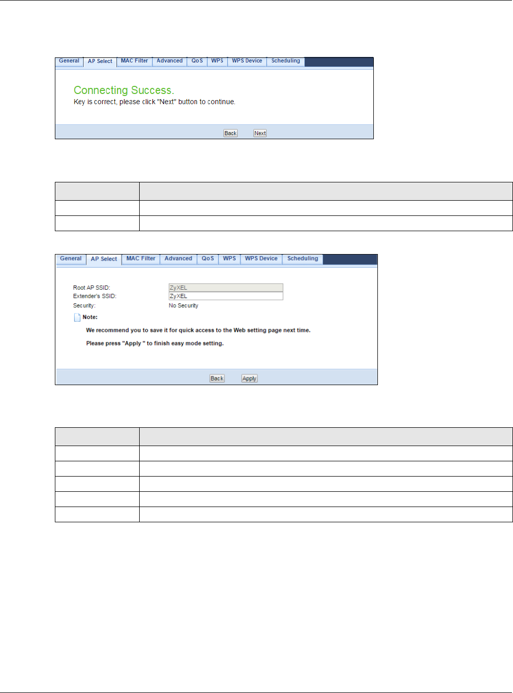
Chapter 9 Universal Repeater Mode
NBG6515 User’s Guide
71
After you selected one of APs and click the Next button, the screen will display as below.
Figure 53 Network > Wireless LAN 5G > AP Select: Connecting Success
The following table describes the labels in this screen.
Figure 54 Network > Wireless LAN 5G > AP Select: Root AP SSID
The following table describes the labels in this screen.
Table 35 Network > Wireless LAN 5G > AP Select: Connecting Success
LABEL DESCRIPTION
Back Click this to return to the previous screen.
Next Click this to continue.
Table 36 Network > Wireless LAN 5G > AP Select: Root AP SSID
LABEL DESCRIPTION
Root AP SSID This field displays the specific AP’s SSID which you used through the NBG.
Extender’s SSID This field displays the SSID of the NBG as an extender.
Security This field displays the specific AP’s security mode which you used through the NBG.
Back Click this to return to the previous screen.
Apply Click Apply to save your changes to the NBG.
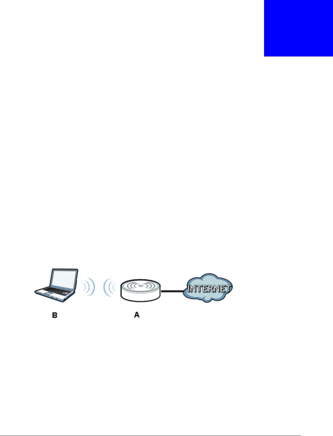
NBG6515 User’s Guide
72
CHAPTER 10
Tutorials
10.1 Overview
This chapter provides tutorials for your NBG as follows:
•Connecting to the Internet from an Access Point
•Configuring Wireless Security Using WPS
•Enabling and Configuring Wireless Security (No WPS)
•If your connection is successful, open your Internet browser and enter http://www.zyxel.com or
the URL of any other web site in the address bar. If you are able to access the web site, your
wireless connection is successfully configured.
10.2 Connecting to the Internet from an Access Point
This section gives you an example of how to set up an access point (AP) and wireless client (a
notebook (B), in this example) for wireless communication. B can access the Internet through the
access point wirelessly.
Figure 55 Wireless Access Point Connection to the Internet
10.3 Configuring Wireless Security Using WPS
This section gives you an example of how to set up wireless network using WPS. This example uses
the NBG as the AP and NWD210N as the wireless client which connects to a notebook.
Note: The wireless client must be a WPS-aware device (for example, a WPS USB adapter
or PCI card).
There are two WPS methods for creating a secure connection. This tutorial shows you how to do
both.

Chapter 10 Tutorials
NBG6515 User’s Guide
73
•Push Button Configuration (PBC) - create a secure wireless network simply by pressing a
button. See Section 10.3.1 on page 73.This is the easier method.
•PIN Configuration - create a secure wireless network simply by entering a wireless client's PIN
(Personal Identification Number) in the NBG’s interface. See Section 10.3.2 on page 74. This is
the more secure method, since one device can authenticate the other.
10.3.1 Push Button Configuration (PBC)
1Make sure that your NBG is turned on and that it is within range of your computer.
2Make sure that you have installed the wireless client (this example uses the NWD210N) driver and
utility in your notebook.
3In the wireless client utility, find the WPS settings. Enable WPS and press the WPS button (Start or
WPS button)
4Log into NBG’s Web Configurator and press the Push Button button in the Network > Wireless
LAN 2.4G or Wireless LAN 5G > WPS Device screen.
Note: Your NBG has a WPS button located on its panel, as well as a WPS button in its
configuration utility. Both buttons have exactly the same function; you can use one
or the other.
Note: It doesn’t matter which button is pressed first. You must press the second button
within two minutes of pressing the first one.
The NBG sends the proper configuration settings to the wireless client. This may take up to two
minutes. Then the wireless client is able to communicate with the NBG securely.
The following figure shows you an example to set up wireless network and security by pressing a
button on both NBG and wireless client (the NWD210N in this example).
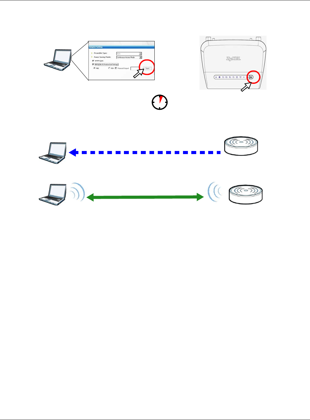
Chapter 10 Tutorials
NBG6515 User’s Guide
74
Figure 56 Example WPS Process: PBC Method
10.3.2 PIN Configuration
When you use the PIN configuration method, you need to use both NBG’s configuration interface
and the client’s utilities.
1Launch your wireless client’s configuration utility. Go to the WPS settings and select the PIN method
to get a PIN number.
2Enter the PIN number to the PIN field in the Network > Wireless LAN 2.4G or Wireless LAN
5G > WPS Device screen on the NBG.
3Click Start button (or button next to the PIN field) on both the wireless client utility screen and the
NBG’s WPS Device screen within two minutes.
The NBG authenticates the wireless client and sends the proper configuration settings to the
wireless client. This may take up to two minutes. Then the wireless client is able to communicate
with the NBG securely.
The following figure shows you the example to set up wireless network and security on NBG and
wireless client (ex. NWD210N in this example) by using PIN method.
Wireless Client Router
SECURITY INFO
COMMUNICATION
WITHIN 2 MINUTES
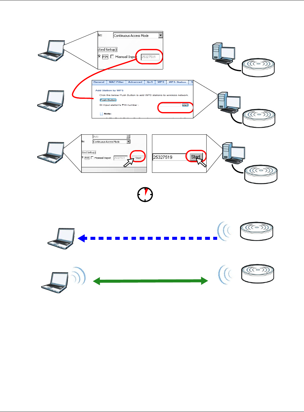
Chapter 10 Tutorials
NBG6515 User’s Guide
75
Figure 57 Example WPS Process: PIN Method
10.4 Enabling and Configuring Wireless Security (No WPS)
This example shows you how to configure wireless security settings with the following parameters
on your NBG.
Authentication by PIN
SECURITY INFO
WITHIN 2 MINUTES
Wireless Client
Router
COMMUNICATION
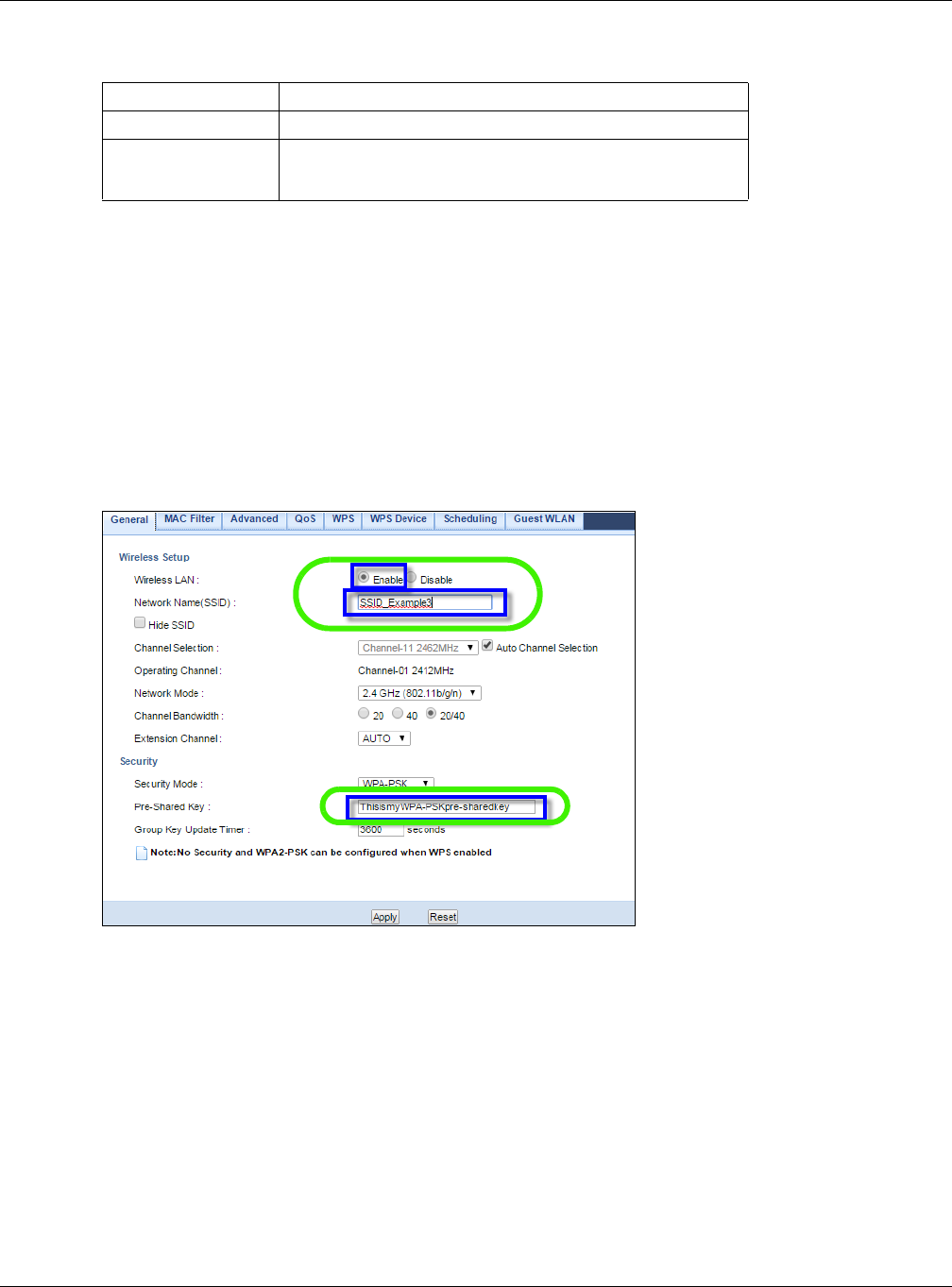
Chapter 10 Tutorials
NBG6515 User’s Guide
76
Follow the steps below to configure the wireless settings on your NBG.
The instructions require that your hardware is connected (see the Quick Start Guide) and you are
logged into the Web Configurator through your LAN connection (see Section 3.2 on page 26).
1Open the Wireless LAN 2.4G/5G > General screen in the AP’s Web Configurator.
2Enable Wireless LAN.
3Enter SSID_Example3 as the SSID and select a channel. Set security mode to WPA-PSK and
enter ThisismyWPA-PSKpre-sharedkey in the Pre-Shared Key field. Click Apply.
Figure 58 Tutorial: Network > Wireless LAN 2.4G/5G > General
4Open the Status screen. Verify your wireless and wireless security settings under Device
Information and check if the WLAN connection is up under Interface Status.
SSID SSID_Example3
Channel 6
Security WPA-PSK
(Pre-Shared Key: ThisismyWPA-PSKpre-sharedkey)
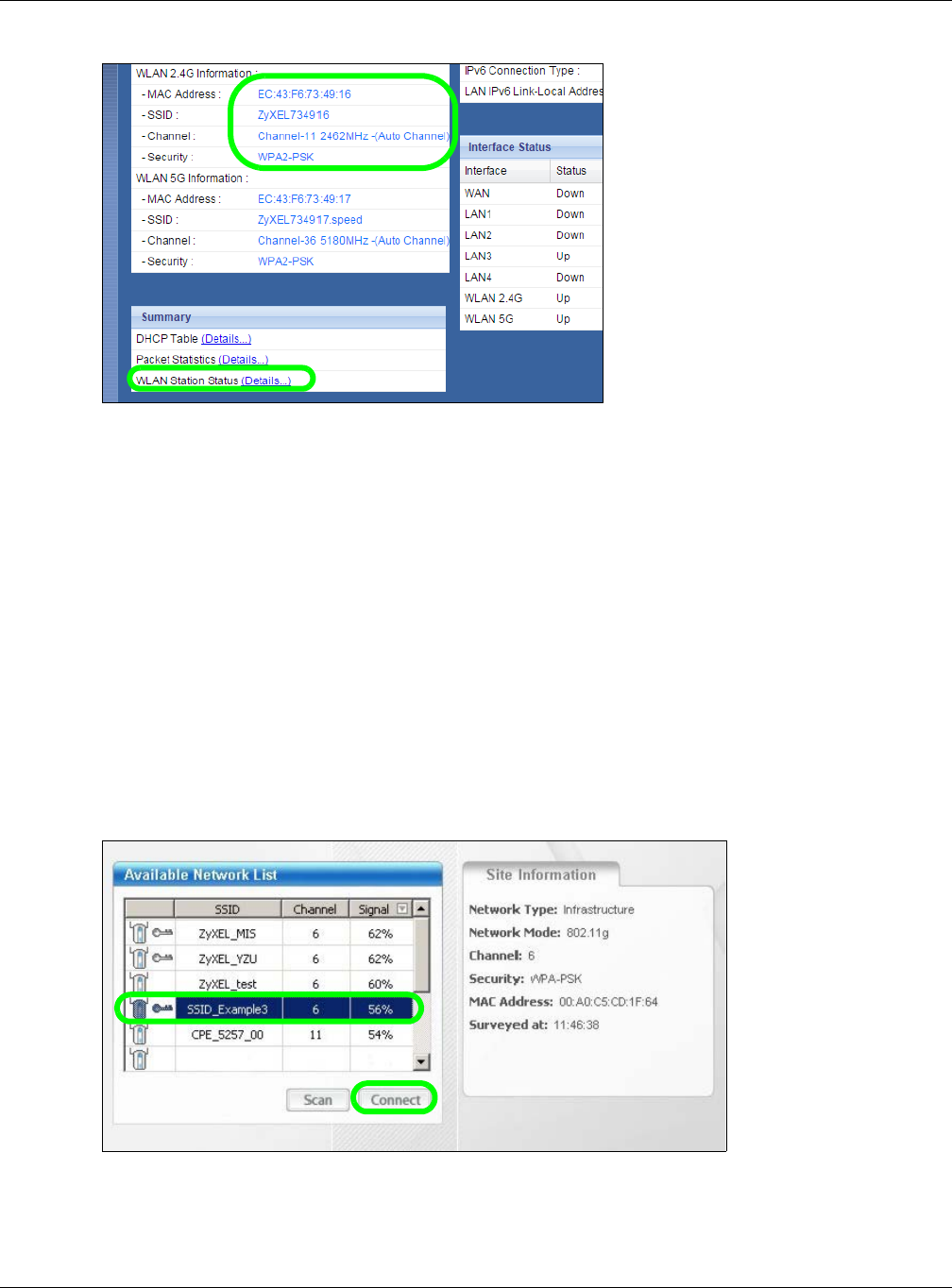
Chapter 10 Tutorials
NBG6515 User’s Guide
77
Figure 59 Tutorial: Checking Wireless Settings
10.4.1 Configure Your Notebook
Note: We use the ZyXEL M-302 wireless adapter utility screens as an example for the
wireless client. The screens may vary for different models.
1The NBG supports IEEE 802.11b, IEEE 802.11g, IEEE 802.11n and IEEE 802.11ac wireless clients.
Make sure that your notebook or computer’s wireless adapter supports one of these standards.
2Wireless adapters come with software sometimes called a “utility” that you install on your
computer. See your wireless adapter’s User’s Guide for information on how to do that.
3After you’ve installed the utility, open it. If you cannot see your utility’s icon on your screen, go to
Start > Programs and click on your utility in the list of programs that appears. The utility displays
a list of APs within range, as shown in the example screen below.
4Select SSID_Example3 and click Connect.
Figure 60 Connecting a Wireless Client to a Wireless Network t
5Select WPA-PSK and type the security key in the following screen. Click Next.
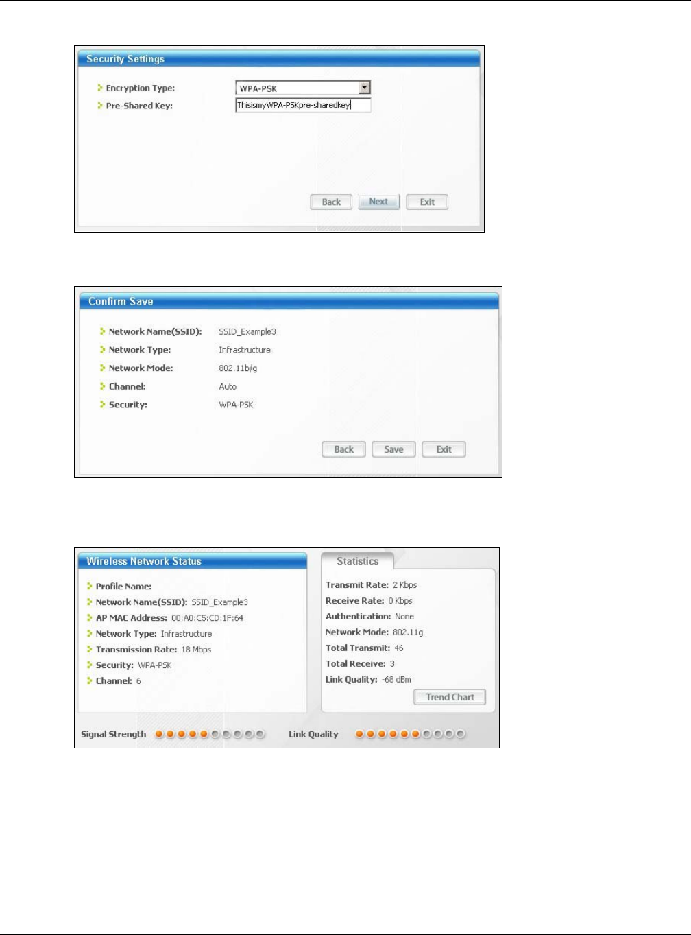
Chapter 10 Tutorials
NBG6515 User’s Guide
78
Figure 61 Security Settings
6The Confirm Save window appears. Check your settings and click Save to continue.
Figure 62 Confirm Save
7Check the status of your wireless connection in the screen below. If your wireless connection is
weak or you have no connection, see the Troubleshooting section of this User’s Guide.
Figure 63 Link Status
If your connection is successful, open your Internet browser and enter http://www.zyxel.com or the
URL of any other web site in the address bar. If you are able to access the web site, your wireless
connection is successfully configured.

79
PART II
Technical Reference
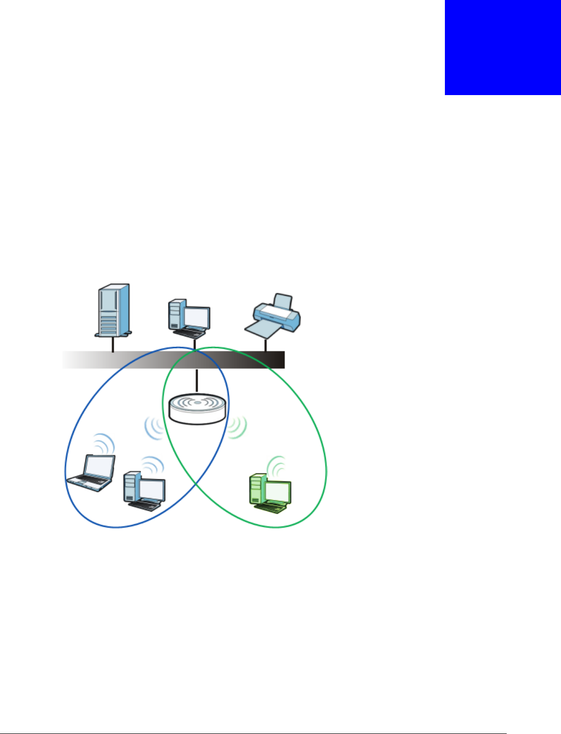
NBG6515 User’s Guide
80
CHAPTER 11
Wireless LAN
11.1 Overview
This chapter discusses how to configure the wireless network settings in your NBG. See the
appendices for more detailed information about wireless networks.
The following figure provides an example of a wireless network.
Figure 64 Example of a Wireless Network
The wireless 2.4G network is the part in the blue circle and wireless 5G network is the part in the
green circle. In these wireless networks, devices A, B and C are called wireless clients. The wireless
clients use the access point (AP) to interact with other devices (such as the printer) or with the
Internet.
11.2 What You Can Do
•Use the General screen (Section 11.4 on page 83) to enable the Wireless LAN, enter the SSID
and select the wireless security mode.
•Use the MAC Filter screen (Section 11.6 on page 89) to allow or deny wireless stations based
on their MAC addresses from connecting to the NBG.
A
B
Router
2.4G 5G
C

Chapter 11 Wireless LAN
NBG6515 User’s Guide
81
•Use the Advanced screen (Section 11.7 on page 90) to allow wireless advanced features, such
as intra-BSS networking and set the RTS/CTS Threshold.
•Use the QoS screen (Section 11.8 on page 91) to set priority levels to services, such as e-mail,
VoIP, chat, and so on.
•Use the WPS screen (Section 11.9 on page 91) to quickly set up a wireless network with strong
security, without having to configure security settings manually.
•Use the WPS Device screen (Section 11.10 on page 92) to add a wireless device using WPS.
•Use the Scheduling screen (Section 11.11 on page 93) to set the times your wireless LAN is
turned on and off.
•Use the Guest WLAN screen (Section 11.12 on page 94) to configure multiple BSSs on the NBG.
11.3 What You Should Know
Every wireless network must follow these basic guidelines.
• Every wireless client in the same wireless network must use the same SSID.
The SSID is the name of the wireless network. It stands for Service Set IDentity.
• If two wireless networks overlap, they should use different channels.
Like radio stations or television channels, each wireless network uses a specific channel, or
frequency, to send and receive information.
• Every wireless client in the same wireless network must use security compatible with the AP.
Security stops unauthorized devices from using the wireless network. It can also protect the
information that is sent in the wireless network.
11.3.1 Wireless Security Overview
The following sections introduce different types of wireless security you can set up in the wireless
network.
11.3.1.1 SSID
Normally, the AP acts like a beacon and regularly broadcasts the SSID in the area. You can hide the
SSID instead, in which case the AP does not broadcast the SSID. In addition, you should change
the default SSID to something that is difficult to guess.
This type of security is fairly weak, however, because there are ways for unauthorized devices to
get the SSID. In addition, unauthorized devices can still see the information that is sent in the
wireless network.
11.3.1.2 MAC Address Filter
Every wireless client has a unique identification number, called a MAC address.1 A MAC address is
usually written using twelve hexadecimal characters2; for example, 00A0C5000002 or
1. Some wireless devices, such as scanners, can detect wireless networks but cannot use wireless networks. These kinds
of wireless devices might not have MAC addresses.
2. Hexadecimal characters are 0, 1, 2, 3, 4, 5, 6, 7, 8, 9, A, B, C, D, E, and F.

Chapter 11 Wireless LAN
NBG6515 User’s Guide
82
00:A0:C5:00:00:02. To get the MAC address for each wireless client, see the appropriate User’s
Guide or other documentation.
You can use the MAC address filter to tell the AP which wireless clients are allowed or not allowed to
use the wireless network. If a wireless client is allowed to use the wireless network, it still has to
have the correct settings (SSID, channel, and security). If a wireless client is not allowed to use the
wireless network, it does not matter if it has the correct settings.
This type of security does not protect the information that is sent in the wireless network.
Furthermore, there are ways for unauthorized devices to get the MAC address of an authorized
wireless client. Then, they can use that MAC address to use the wireless network.
11.3.1.3 Encryption
Wireless networks can use encryption to protect the information that is sent in the wireless
network. Encryption is like a secret code. If you do not know the secret code, you cannot
understand the message.
The types of encryption you can choose depend on the type of user authentication.
Usually, you should set up the strongest encryption that every wireless client in the wireless
network supports. Suppose the wireless network has two wireless clients. Device A only supports
WEP, and device B supports WEP and WPA-PSK. Therefore, you should set up WEP in the wireless
network.
Note: It is recommended that wireless networks use WPA-PSK or stronger encryption.
IEEE 802.1x and WEP encryption are better than none at all, but it is still possible
for unauthorized devices to figure out the original information pretty quickly.
When you select WPA2-PSK in your NBG, you can also select an option (WPA Compatible) to
support WPA as well. In this case, if some wireless clients support WPA and some support WPA2,
you should set up WPA2-PSK (depending on the type of wireless network login) and select the
WPA Compatible option in the NBG.
Many types of encryption use a key to protect the information in the wireless network. The longer
the key, the stronger the encryption. Every wireless client in the wireless network must have the
same key.
11.3.1.4 WPS
WiFi Protected Setup (WPS) is an industry standard specification, defined by the WiFi Alliance. WPS
allows you to quickly set up a wireless network with strong security, without having to configure
security settings manually. Depending on the devices in your network, you can either press a
button (on the device itself, or in its configuration utility) or enter a PIN (Personal Identification
Number) in the devices. Then, they connect and set up a secure network by themselves. See how
to set up a secure wireless network using WPS in the Section 10.3 on page 72.
Table 37 Types of Encryption for Each Type of Authentication
NO AUTHENTICATION
Weakest No Security
WEP
WPA-PSK
Strongest WPA2-PSK

Chapter 11 Wireless LAN
NBG6515 User’s Guide
83
11.3.1.5 WDS
Wireless Distribution System or WDS security is used between bridged APs. It is independent of the
security between the wired networks and their respective APs. If you do not enable WDS security,
traffic between APs is not encrypted. When WDS security is enabled, both APs must use the same
pre-shared key.
11.4 General Wireless LAN 2.4G/5G General Screen
Use this screen to enable the Wireless LAN 2.4G or 5G, enter the SSID and enable Guest WLAN.
Note: If you are configuring the NBG from a computer connected to the wireless LAN and
you change the NBG’s SSID, channel or security settings, you will lose your
wireless connection when you press Apply to confirm. You must then change the
wireless settings of your computer to match the NBG’s new settings.
This screen varies depending on whether you chose Static WEP, WPA, WPA2, WPA-PSK or
WPA2-PSK to add security on the selected wireless network. The wireless clients which want to
associate to this network must have same wireless security settings as the NBG. No Security
allows any client to connect to this network without authentication.
If you enable the WPS function, only No Security, Static WEP, WPA-PSK and WPA2-PSK are
available in this field.
Click Network > Wireless LAN 2.4G or Wireless LAN 5G to open the General screen.
Figure 65 Network > Wireless LAN 2.4G/5G > General

Chapter 11 Wireless LAN
NBG6515 User’s Guide
84
The following table describes the general wireless LAN labels in this screen.
Table 38 Network > Wireless LAN 2.4G/5G > General
LABEL DESCRIPTION
Wireless Setup
Wireless LAN Select the radio button to Enable or Disable Wireless LAN.
You can turn the wireless LAN on or off using the switch at the rear panel of the NBG.
Network Name
(SSID)
(Service Set IDentity) The SSID identifies the Service Set with which a wireless station is
associated. Wireless stations associating to the NBG must have the same SSID. Enter a
descriptive name (up to 32 keyboard characters) for the wireless LAN.
Hide SSID Select this check box to hide the SSID in the outgoing beacon frame so a station cannot
obtain the SSID through scanning using a site survey tool.
Channel
Selection
Set the operating frequency/channel depending on your particular region.
Select a channel from the drop-down list box. The options vary depending on the frequency
band and the country you are in.
Refer to the Connection Wizard chapter for more information on channels. This option is
only available if Auto Channel Selection is disabled.
Operating
Channel
This displays the channel the NBG is currently using.
Network Mode
(Wireless LAN
2.4G)
Select 11b/g mixed mode to allow IEEE802.11b and IEEE802.11g compliant WLAN
devices to associate with the NBG.
Select 11b only to allow only IEEE 802.11b compliant WLAN devices to associate with the
NBG.
Select 11g only to allow only IEEE 802.11g compliant WLAN devices to associate with the
NBG.
Select 11n only to allow only IEEE 802.11n compliant WLAN devices to associate with the
NBG.
Select 11b/g/n mixed mode to allow IEEE802.11b, IEEE802.11g and IEEE802.11n
compliant WLAN devices to associate with the NBG.
Network Mode
(Wireless LAN
5G)
Select 11a/n mixed mode to allow IEEE802.11a and IEEE802.11n compliant WLAN
devices to associate with the NBG.
Select 11a only to allow only IEEE 802.11a compliant WLAN devices to associate with the
NBG.
Select 11ac/a/n to allow only IEEE 802.11a, IEEE802.11an and IEEE802.11ac compliant
WLAN devices to associate with the NBG.
Channel
Bandwidth
Select the channel bandwidth you want to use for your wireless network.
It is recommended that you select 20/40 (20, 40, 20/40 MHz).
Select 20 MHz if you want to lessen radio interference with other wireless devices in your
neighborhood.
Extension
Channel
This is set to Auto by default.
If you select 20/40 as your Channel Bandwidth, the extension channel enables the NBG
to get higher data throughput. This also lowers radio interference and traffic.
Security
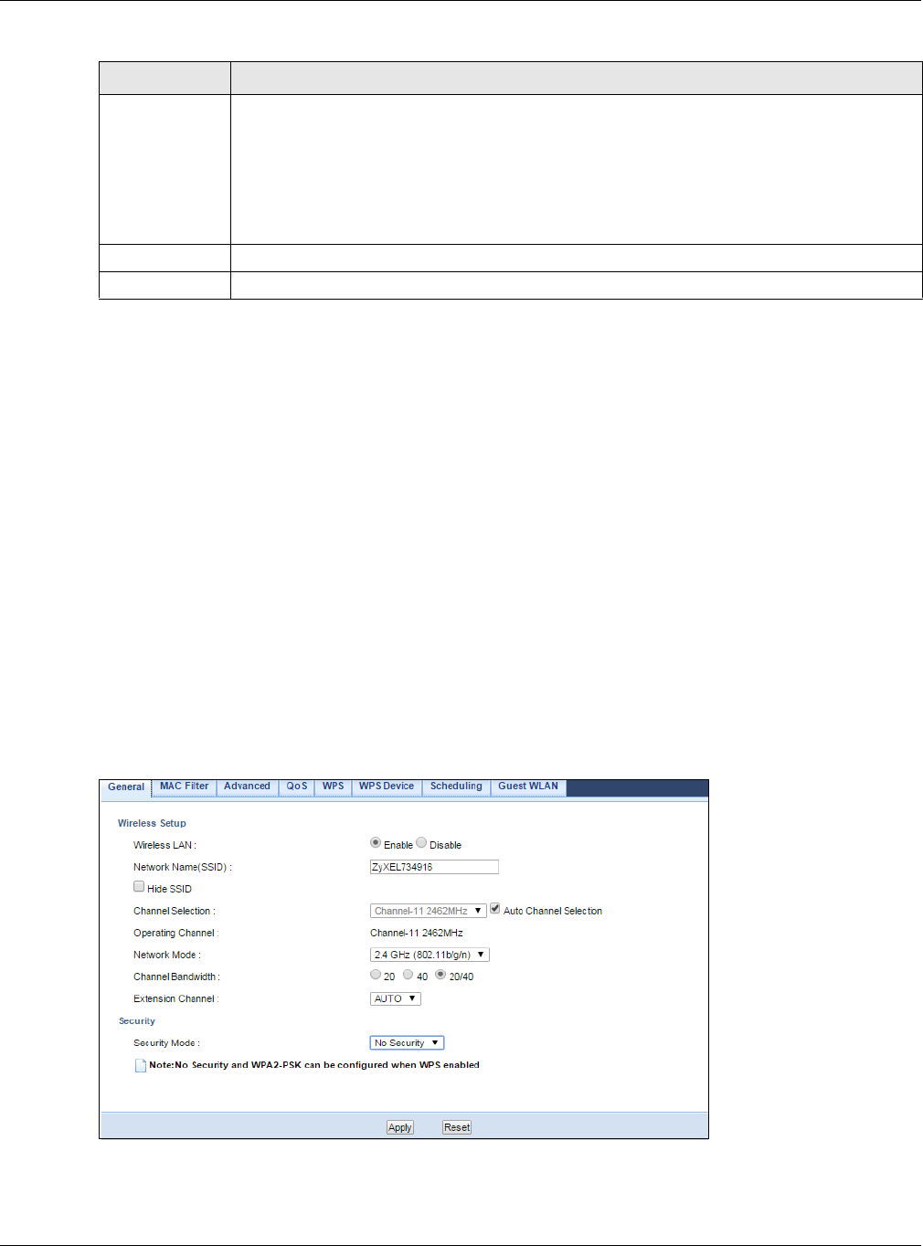
Chapter 11 Wireless LAN
NBG6515 User’s Guide
85
See the rest of this chapter for information on the other labels in this screen.
11.5 General Wireless LAN 2.4G/5G Security Screen
This screen varies depending on whether you chose Static WEP, WPA-PSK or WPA2-PSK to add
security on the selected wireless network. The wireless clients which want to associate to this
network must have same wireless security settings as the NBG. No Security allows any client to
connect to this network without authentication.
11.5.1 No Security
Select No Security to allow wireless stations to communicate with the access points without any
data encryption.
Note: If you do not enable any wireless security on your NBG, your network is accessible
to any wireless networking device that is within range.
Figure 66 Network > Wireless LAN 2.4G/5G > General: No Security
Security Mode Select Static WEP, WPA-PSK, WPA2-PSK to add security on this wireless network. The
wireless clients which want to associate to this network must have same wireless security
settings as this device. After you select to use a security, additional options appears in this
screen. Section 11.5 on page 85 for detailed information on different security modes. Or you
can select No Security to allow any client to associate this network without authentication.
Note: If the WPS function is enabled (default), only No Security and WPA2-PSK are
available in this field.
Apply Click Apply to save your changes back to the NBG.
Reset Click Reset to begin configuring this screen afresh.
Table 38 Network > Wireless LAN 2.4G/5G > General (continued)
LABEL DESCRIPTION

Chapter 11 Wireless LAN
NBG6515 User’s Guide
86
The following table describes the labels in this screen.
Refer to Table 38 on page 84 for descriptions of the other labels in this screen.
11.5.2 WEP Encryption
WEP encryption scrambles the data transmitted between the wireless stations and the access points
to keep network communications private. It encrypts unicast and multicast communications in a
network. Both the wireless stations and the access points must use the same WEP key.
Your NBG allows you to configure up to four 64-bit or 128-bit WEP keys but only one key can be
enabled at any one time.
In order to configure and enable WEP encryption, click Network > Wireless LAN 2.4G or
Wireless LAN 5G to display the General screen. Select Static WEP from the Security Mode list.
Table 39 Network > Wireless LAN 2.4G/5G > General: No Security
LABEL DESCRIPTION
Security Mode Choose No Security from the drop-down list box.
Apply Click Apply to save your changes back to the NBG.
Reset Click Reset to begin configuring this screen afresh.
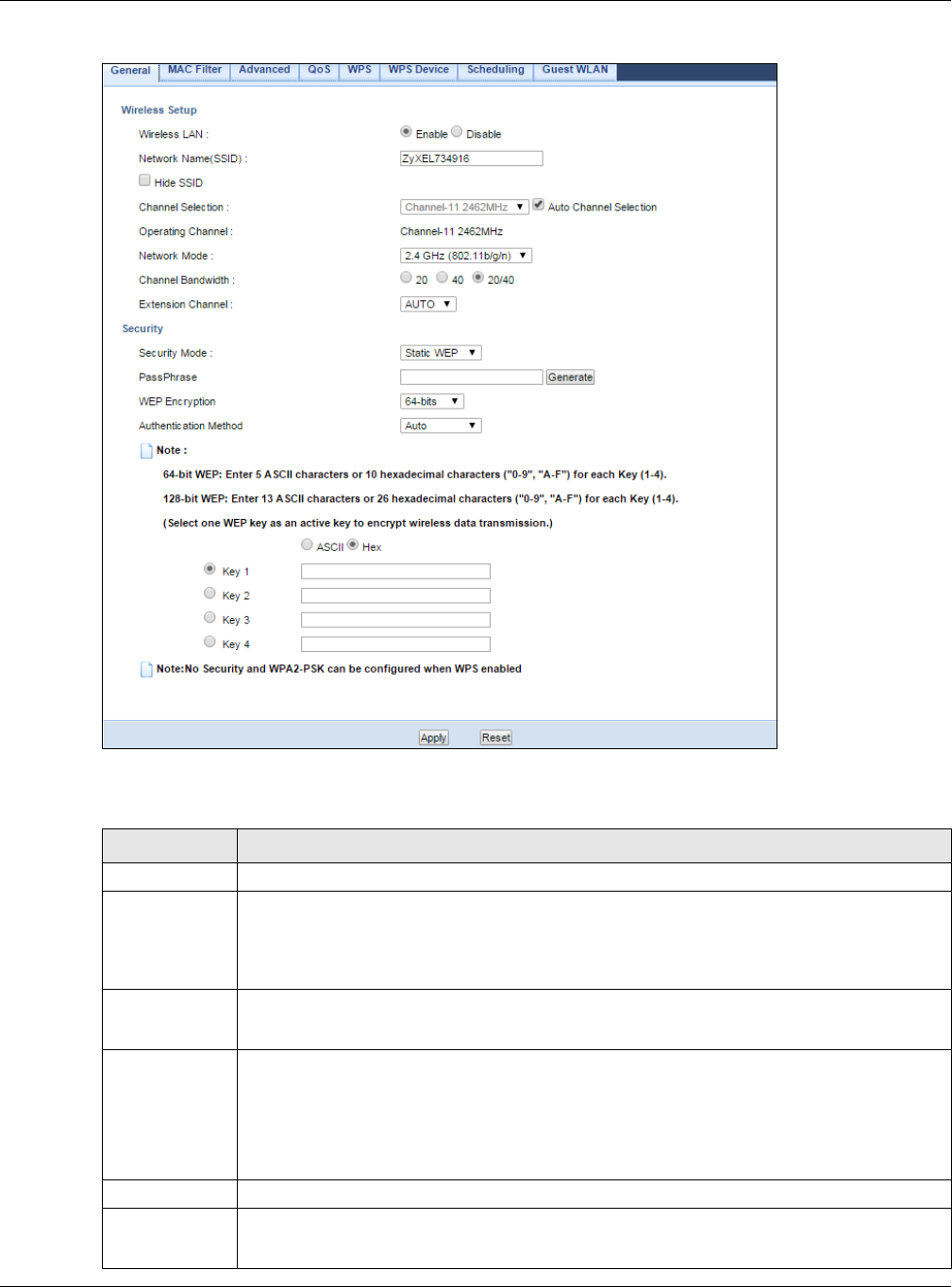
Chapter 11 Wireless LAN
NBG6515 User’s Guide
87
Figure 67 Network > Wireless LAN 2.4G/5G > General: Static WEP
The following table describes the wireless LAN security labels in this screen.
Table 40 Network > Wireless LAN 2.4G/5G > General: Static WEP
LABEL DESCRIPTION
Security Mode Select Static WEP to enable data encryption.
PassPhrase Enter a Passphrase (up to 26 printable characters) and click Generate.
A passphrase functions like a password. In WEP security mode, it is further converted by the
NBG into a complicated string that is referred to as the “key”. This key is requested from all
devices wishing to connect to a wireless network.
WEP Encryption Select 64-bit WEP or 128-bit WEP.
This dictates the length of the security key that the network is going to use.
Authentication
Method
Select Auto or Shared Key from the drop-down list box.
This field specifies whether the wireless clients have to provide the WEP key to login to the
wireless client. Keep this setting at Auto unless you want to force a key verification before
communication between the wireless client and the NBG occurs.
Select Shared Key to force the clients to provide the WEP key prior to communication.
ASCII Select this option in order to enter ASCII characters as WEP key.
Hex Select this option in order to enter hexadecimal characters as a WEP key.
The preceding "0x", that identifies a hexadecimal key, is entered automatically.
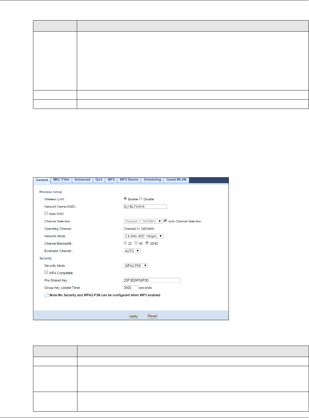
Chapter 11 Wireless LAN
NBG6515 User’s Guide
88
Refer to Table 38 on page 84 for descriptions of the other labels in this screen.
11.5.3 WPA-PSK/WPA2-PSK
Click Network > Wireless LAN 2.4G or Wireless LAN 5G to display the General screen. Select
WPA-PSK or WPA2-PSK from the Security Mode list.
Figure 68 Network > Wireless LAN 2.4G/5G> General: WPA-PSK/WPA2-PSK
The following table describes the labels in this screen.
Key 1 to Key 4 The WEP keys are used to encrypt data. Both the NBG and the wireless stations must use
the same WEP key for data transmission.
If you chose 64-bit WEP, then enter any 5 ASCII characters or 10 hexadecimal characters
("0-9", "A-F").
If you chose 128-bit WEP, then enter 13 ASCII characters or 26 hexadecimal characters
("0-9", "A-F").
You must configure at least one key, only one key can be activated at any one time.
Apply Click Apply to save your changes back to the NBG.
Reset Click Reset to begin configuring this screen afresh.
Table 40 Network > Wireless LAN 2.4G/5G > General: Static WEP (continued)
LABEL DESCRIPTION
Table 41 Network > Wireless LAN 2.4G/5G > General: WPA-PSK/WPA2-PSK
LABEL DESCRIPTION
Security Mode Select WPA-PSK or WPA2-PSK to enable data encryption.
WPA
Compatible
This field appears when you choose WPA-PSK2 as the Security Mode.
Check this field to allow wireless devices using WPA-PSK security mode to connect to your
NBG.
Pre-Shared Key WPA-PSK/WPA2-PSK uses a simple common password for authentication.
Type a pre-shared key from 8 to 63 case-sensitive keyboard characters.
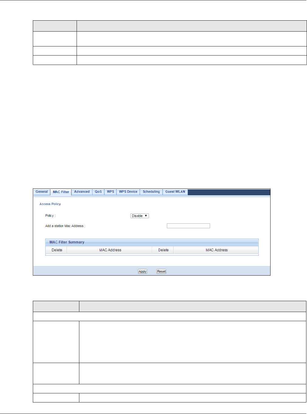
Chapter 11 Wireless LAN
NBG6515 User’s Guide
89
Refer to Table 38 on page 84 for descriptions of the other labels in this screen.
11.6 MAC Filter
The MAC filter screen allows you to configure the NBG to give exclusive access to devices (Allow) or
exclude devices from accessing the NBG (Deny). Every Ethernet device has a unique MAC (Media
Access Control) address. The MAC address is assigned at the factory and consists of six pairs of
hexadecimal characters, for example, 00:A0:C5:00:00:02. You need to know the MAC address of
the devices to configure this screen.
To change your NBG’s MAC filter settings, click Network > Wireless LAN 2.4G or Wireless LAN
5G > MAC Filter. The screen appears as shown.
Figure 69 Network > Wireless LAN 2.4G/5G > MAC Filter
The following table describes the labels in this menu.
Group Key
Update Timer
The Group Key Update Timer is the rate at which the AP sends a new group key out to all
clients.
Apply Click Apply to save your changes back to the NBG.
Reset Click Reset to begin configuring this screen afresh.
Table 41 Network > Wireless LAN 2.4G/5G > General: WPA-PSK/WPA2-PSK (continued)
LABEL DESCRIPTION
Table 42 Network > Wireless LAN 2.4G/5G > MAC Filter
LABEL DESCRIPTION
Access Policy
Policy Define the filter action for the list of MAC addresses in the MAC Address table.
Select Allow to permit access to the NBG, MAC addresses not listed will be denied access
to the NBG.
Select Disable to block access to the NBG, MAC addresses not listed will be allowed to
access the NBG
Add a station
Mac Address
Enter the MAC addresses of the wireless station that are allowed or denied access to the
NBG in these address fields. Enter the MAC addresses in a valid MAC address format, that
is, six hexadecimal character pairs, for example, 12:34:56:78:9a:bc. Click Add.
MAC Filter Summary
Delete Click the delete icon to remove the MAC address from the list.
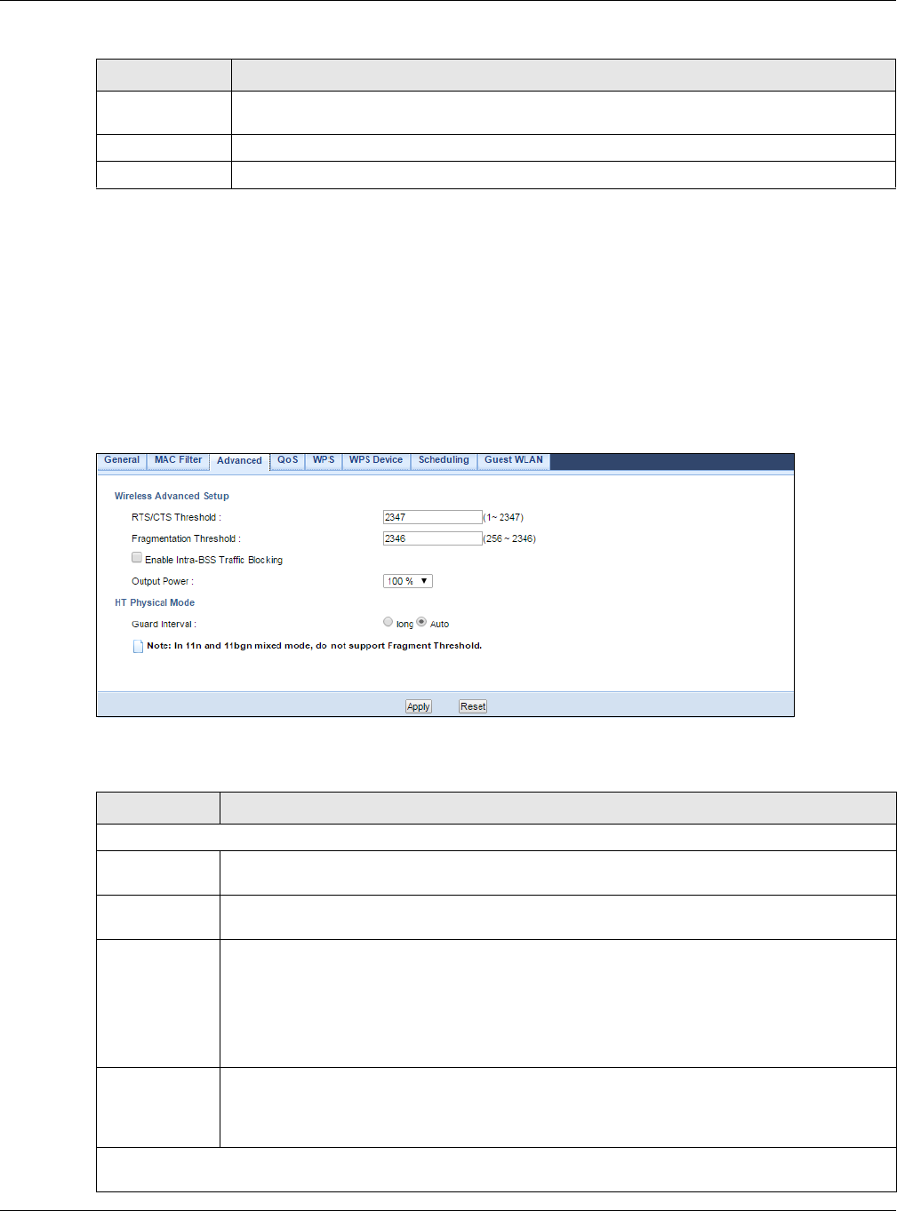
Chapter 11 Wireless LAN
NBG6515 User’s Guide
90
11.7 Wireless LAN Advanced Screen
Use this screen to allow wireless advanced features, such as intra-BSS networking and set the
RTS/CTS Threshold
Click Network > Wireless LAN 2.4G or Wireless LAN 5G > Advanced. The screen appears as
shown.
Figure 70 Network > Wireless LAN 2.4G/5G > Advanced
The following table describes the labels in this screen.
MAC Address This is the MAC address of the wireless station that are allowed or denied access to the
NBG.
Apply Click Apply to save your changes back to the NBG.
Reset Click Reset to begin configuring this screen afresh.
Table 42 Network > Wireless LAN 2.4G/5G > MAC Filter (continued)
LABEL DESCRIPTION
Table 43 Network > Wireless LAN 2.4G/5G > Advanced
LABEL DESCRIPTION
Wireless Advanced Setup
RTS/CTS
Threshold
Data with its frame size larger than this value will perform the RTS (Request To Send)/CTS
(Clear To Send) handshake.
Fragmentation
Threshold
The threshold (number of bytes) for the fragmentation boundary for directed messages. It is
the maximum data fragment size that can be sent. Enter an even number.
Enable Intra-
BSS Traffic
Blocking
A Basic Service Set (BSS) exists when all communications between wireless clients or
between a wireless client and a wired network client go through one access point (AP).
Intra-BSS traffic is traffic between wireless clients in the BSS. When Intra-BSS is enabled,
wireless client A and B can access the wired network and communicate with each other.
When Intra-BSS is disabled, wireless client A and B can still access the wired network but
cannot communicate with each other.
Output Power Set the output power of the NBG in this field. If there is a high density of APs in an area,
decrease the output power of the NBG to reduce interference with other APs. Select one of
the following 100%, 90%, 75%, 50%, 25%, 10% or Minimum. See the product
specifications for more information on your NBG’s output power.
HT (High Throughput) Physical Mode - Use the fields below to configure the 802.11 wireless environment of
your NBG.
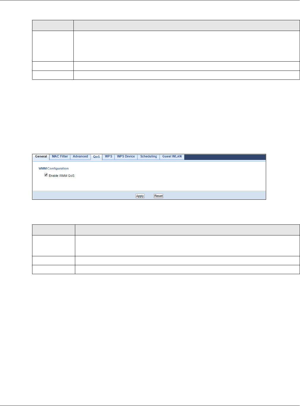
Chapter 11 Wireless LAN
NBG6515 User’s Guide
91
11.8 Quality of Service (QoS) Screen
The QoS screen allows you to automatically give a service (such as VoIP and video) a priority level.
Click Network > Wireless LAN 2.4G or Wireless LAN 5G > QoS. The following screen appears.
Figure 71 Network > Wireless LAN 2.4G/5G > QoS
The following table describes the labels in this screen.
11.9 WPS Screen
Use this screen to enable/disable WPS, view or generate a new PIN number and check current WPS
status. To open this screen, click Network > Wireless LAN 2.4G or Wireless LAN 5G > WPS
tab.
Guard Interval Select Auto to increase data throughput. However, this may make data transfer more prone
to errors.
Select Long to prioritize data integrity. This may be because your wireless network is busy
and congested or the NBG is located in an environment prone to radio interference.
Apply Click Apply to save your changes back to the NBG.
Reset Click Reset to begin configuring this screen afresh.
Table 43 Network > Wireless LAN 2.4G/5G > Advanced (continued)
LABEL DESCRIPTION
Table 44 Network > Wireless LAN 2.4G/5G > QoS
LABEL DESCRIPTION
Enable WMM
QoS
Check this to have the NBG automatically give a service a priority level according to the ToS
value in the IP header of packets it sends. WMM QoS (Wifi MultiMedia Quality of Service)
gives high priority to voice and video, which makes them run more smoothly.
Apply Click Apply to save your changes to the NBG.
Reset Click Reset to begin configuring this screen afresh.
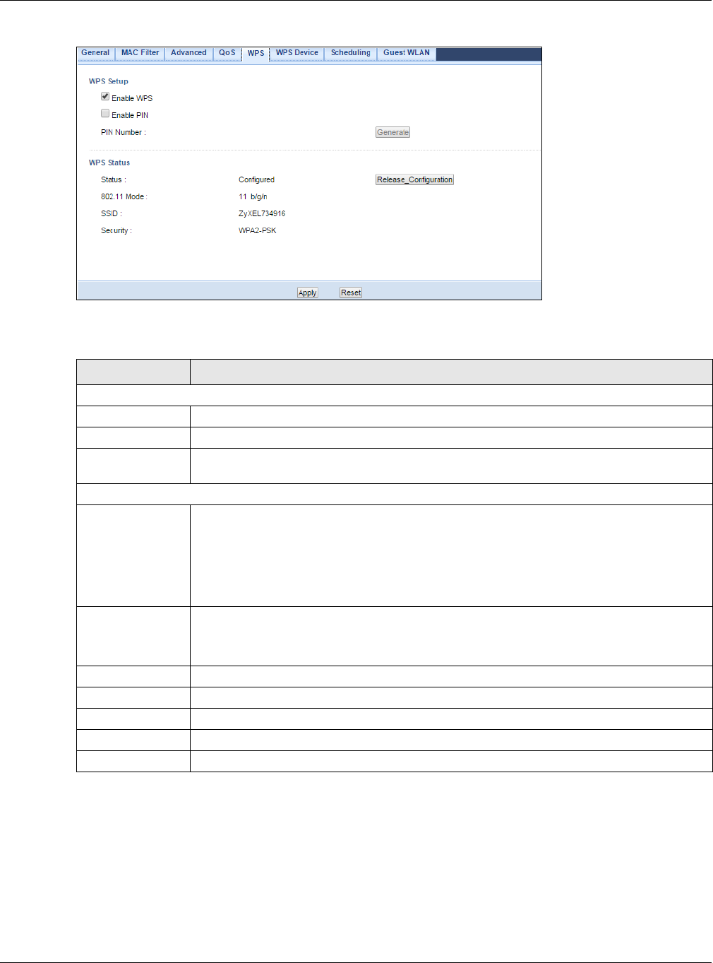
Chapter 11 Wireless LAN
NBG6515 User’s Guide
92
Figure 72 Network > Wireless LAN 2.4G/5G > WPS
The following table describes the labels in this screen.
11.10 WPS Device Screen
Use this screen when you want to add a wireless station using WPS. To open this screen, click
Network > Wireless LAN 2.4G or Wireless LAN 5G > WPS Station tab.
Table 45 Network > Wireless LAN 2.4G/5G > WPS
LABEL DESCRIPTION
WPS Setup
Enable WPS Select this to enable the WPS feature.
Enable PIN Select this to enable the WPS feature.
PIN Number This displays a PIN number last time system generated. Click Generate to generate a
new PIN number.
WPS Status
Status This displays Configured when the NBG has connected to a wireless network using WPS
or when Enable WPS is selected and wireless or wireless security settings have been
changed. The current wireless and wireless security settings also appear in the screen.
This displays Unconfigured if WPS is disabled and there are no wireless or wireless
security changes on the NBG or you click Release_Configuration to remove the
configured wireless and wireless security settings.
Release
Configuration
This button is only available when the WPS status displays Configured.
Click this button to remove all configured wireless and wireless security settings for WPS
connections on the NBG.
802.11 Mode This is the 802.11 mode used. Only compliant WLAN devices can associate with the NBG.
SSID This is the name of the wireless network.
Security This is the type of wireless security employed by the network.
Apply Click Apply to save your changes back to the NBG.
Reset Click Reset to begin configuring this screen afresh.
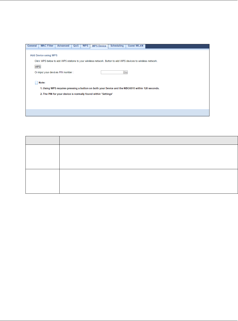
Chapter 11 Wireless LAN
NBG6515 User’s Guide
93
Note: Note: After you click Push Button on this screen, you have to press a similar
button in the wireless station utility within 2 minutes. To add the second wireless
station, you have to press these buttons on both device and the wireless station
again after the first 2 minutes.
Figure 73 Network > Wireless LAN 2.4G/5G > WPS Device
The following table describes the labels in this screen.
11.11 Scheduling Screen
Use this screen to set the times your wireless LAN is turned on and off. Wireless LAN scheduling is
disabled by default. The wireless LAN can be scheduled to turn on or off on certain days and at
certain times. To open this screen, click Network > Wireless LAN 2.4G or Wireless LAN 5G >
Scheduling tab.
Table 46 Network > Wireless LAN 2.4G/5G > WPS Station
LABEL DESCRIPTION
WPS Use this button when you use the PBC (Push Button Configuration) method to configure
wireless stations’s wireless settings. See Section 10.3.1 on page 73.
Click this to start WPS-aware wireless station scanning and the wireless security information
synchronization.
Or input your
devices PIN
number
Use this button when you use the PIN Configuration method to configure wireless station’s
wireless settings. See Section 10.3.2 on page 74.
Type the same PIN number generated in the wireless station’s utility. Then click Go to
associate to each other and perform the wireless security information synchronization.
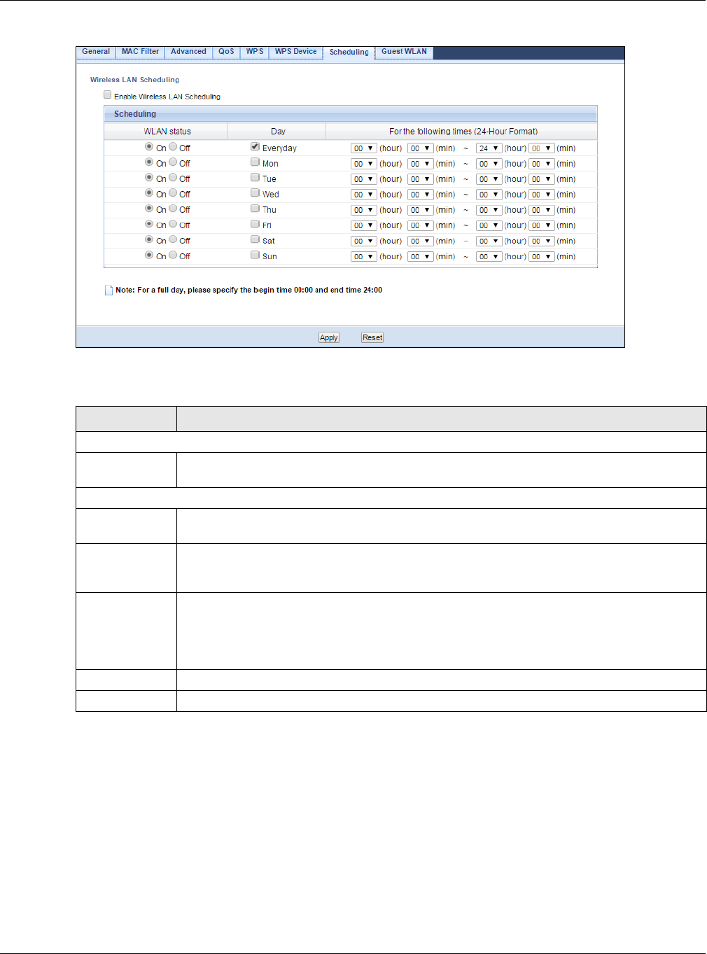
Chapter 11 Wireless LAN
NBG6515 User’s Guide
94
Figure 74 Network > Wireless LAN 2.4G/5G > Scheduling
The following table describes the labels in this screen.
11.12 Guest WLAN Screen
This screen allows you to enable and configure multiple wireless networks and guest wireless
network settings on the NBG.
You can configure up to four SSIDs to enable multiple BSSs (Basic Service Sets) on the NBG. This
allows you to use one access point to provide several BSSs simultaneously. You can then assign
varying security types to different SSIDs. Wireless clients can use different SSIDs to associate with
the same access point.
Table 47 Network > Wireless LAN 2.4G/5G > Scheduling
LABEL DESCRIPTION
Wireless LAN Scheduling
Enable Wireless
LAN Scheduling
Select this to enable Wireless LAN scheduling.
Scheduling
WLAN Status Select On or Off to specify whether the Wireless LAN is turned on or off. This field works in
conjunction with the Day and For the following times fields.
Day Select Everyday or the specific days to turn the Wireless LAN on or off. If you select
Everyday you can not select any specific days. This field works in conjunction with the For
the following times field.
For the
following times
(24-Hour
Format)
Select a begin time using the first set of hour and minute (min) drop down boxes and
select an end time using the second set of hour and minute (min) drop down boxes. If you
have chosen On earlier for the WLAN Status the Wireless LAN will turn on between the two
times you enter in these fields. If you have chosen Off earlier for the WLAN Status the
Wireless LAN will turn off between the two times you enter in these fields.
Apply Click Apply to save your changes back to the NBG.
Reset Click Reset to begin configuring this screen afresh.
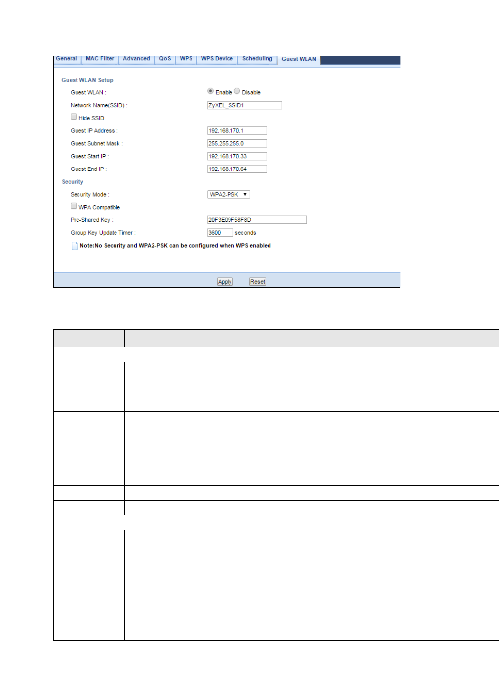
Chapter 11 Wireless LAN
NBG6515 User’s Guide
95
Click Network > Wireless LAN 2.4G/5G > Guest WLAN. The following screen displays.
Figure 75 Network > Wireless LAN 2.4G/5G > Guest WLAN
The following table describes the labels in this screen.
Table 48 Network > Wireless LAN 2.4G > Guest WLAN
LABEL DESCRIPTION
Guest WLAN Setup
Guest WLAN Select Enable to activate the guest wireless LAN. Select Disable to turn it off.
Network
Name(SSID)
The SSID (Service Set IDentity) identifies the Service Set with which a wireless client is
associated. Enter a descriptive name (up to 32 printable characters found on a typical
English language keyboard) for the wireless LAN.
Hide SSID Select this check box to hide the SSID in the outgoing beacon frame so a station cannot
obtain the SSID through scanning using a site survey tool.
Guest IP
Address
Type an IP address for the devices on the Guest WLAN using this as the gateway IP address.
Guest Subnet
Mask
Type the subnet mask for the guest wireless LAN.
Guest Start IP This field displays the first IP address of guest wireless LAN.
Guest End IP This field displays the last IP address of guest wireless LAN.
Security
Security Mode Select Static WEP, WPA-PSK, WPA2-PSK to add security on this wireless network. The
wireless clients which want to associate to this network must have same wireless security
settings as this device. After you select to use a security, additional options appears in this
screen. Section 11.5 on page 85 for detailed information on different security modes. Or you
can select No Security to allow any client to associate this network without authentication.
Note: If the WPS function is enabled (default), only No Security and WPA2-PSK are
available in this field.
Apply Click Apply to save your changes to NBG.
Reset Click Reset to begin configuring this screen afresh.

NBG6515 User’s Guide
96
CHAPTER 12
IPv6
12.1 IPv6 Overview
IPv6 (Internet Protocol version 6), is designed to enhance IP address size and features. The
increase in IPv6 address size to 128 bits (from the 32-bit IPv4 address) allows up to 3.4 x 1038 IP
addresses.
Use the IPv6 screens to configure the IP address for your NBG on the LAN or on the WAN.
12.1.1 What You Can Do in this Chapter
•Use the General screen (Section 12.2 on page 98) to configure the IPv6 connection type.
12.1.2 What You Need to Know
IPv6 Addressing
An 128-bit IPv6 address is written as eight 16-bit hexadecimal blocks separated by colons (:). This
is an example IPv6 address 2001:0db8:1a2b:0015:0000:0000:1a2f:0000.
IPv6 addresses can be abbreviated in two ways:
• Leading zeros in a block can be omitted. So 2001:0db8:1a2b:0015:0000:0000:1a2f:0000 can
be written as 2001:db8:1a2b:15:0:0:1a2f:0.
• Any number of consecutive blocks of zeros can be replaced by a double colon. A double colon can
only appear once in an IPv6 address. So 2001:0db8:0000:0000:1a2f:0000:0000:0015 can be
written as 2001:0db8::1a2f:0000:0000:0015, 2001:0db8:0000:0000:1a2f::0015,
2001:db8::1a2f:0:0:15 or 2001:db8:0:0:1a2f::15.
Prefix and Prefix Length
Similar to an IPv4 subnet mask, IPv6 uses an address prefix to represent the network address. An
IPv6 prefix length specifies how many most significant bits (start from the left) in the address
compose the network address. The prefix length is written as “/x” where x is a number. For
example,
2001:db8:1a2b:15::1a2f:0/32
means that the first 32 bits (2001:db8) from the left is the network prefix.

Chapter 12 IPv6
NBG6515 User’s Guide
97
Link-local Address
A link-local address uniquely identifies a device on the local network (the LAN). It is similar to a
“private IP address” in IPv4. You can have the same link-local address on multiple interfaces on a
device. A link-local unicast address has a predefined prefix of fe80::/10. The link-local unicast
address format is as follows.
Subnet Masking
Both an IPv6 address and IPv6 subnet mask compose of 128-bit binary digits, which are divided
into eight 16-bit blocks and written in hexadecimal notation. Hexadecimal uses four bits for each
character (1 ~ 10, A ~ F). Each block’s 16 bits are then represented by four hexadecimal
characters. For example, FFFF:FFFF:FFFF:FFFF:FC00:0000:0000:0000.
Stateless Autoconfiguration
With stateless autoconfiguration in IPv6, addresses can be uniquely and automatically generated.
Unlike DHCPv6 (Dynamic Host Configuration Protocol version six) which is used in IPv6 stateful
autoconfiguration, the owner and status of addresses don’t need to be maintained by a DHCP
server. Every IPv6 device is able to generate its own and unique IP address automatically when
IPv6 is initiated on its interface. It combines the prefix and the interface ID (generated from its own
Ethernet MAC address) to form a complete IPv6 address.
When IPv6 is enabled on a device, its interface automatically generates a link-local address
(beginning with fe80).
When the NBG’s WAN interface is connected to an ISP with a router and the NBG is set to
automatically obtain an IPv6 network prefix from the router for the interface, it generates another
address which combines its interface ID and global and subnet information advertised from the
router. (In IPv6, all network interfaces can be associated with several addresses.) This is a routable
global IP address.
Prefix Delegation
Prefix delegation enables an IPv6 router (the NBG) to use the IPv6 prefix (network address)
received from the ISP (or a connected uplink router) for its LAN. The NBG uses the received IPv6
prefix (for example, 2001:db2::/48) to generate its LAN IP address. Through sending Router
Advertisements (RAs) regularly by multicast, the router passes the IPv6 prefix information to its
LAN hosts. The hosts then can use the prefix to generate their IPv6 addresses.
IPv6 Router Advertisement
An IPv6 router sends router advertisement messages periodically to advertise its presence and
other parameters to the hosts in the same network.
Table 49 Link-local Unicast Address Format
1111 1110 10 0 Interface ID
10 bits 54 bits 64 bits
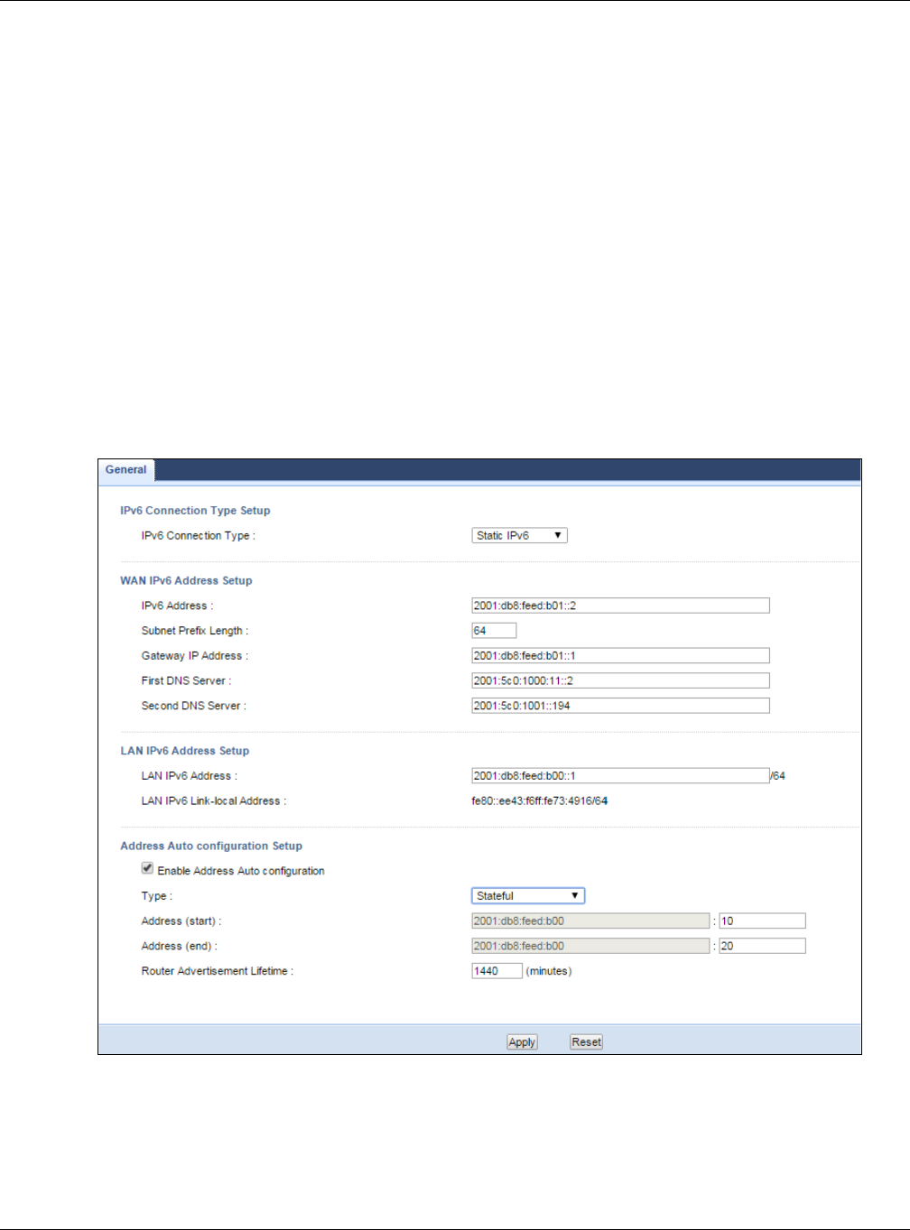
Chapter 12 IPv6
NBG6515 User’s Guide
98
DHCPv6
The Dynamic Host Configuration Protocol for IPv6 (DHCPv6, RFC 3315) is a server-client protocol
that allows a DHCP server to assign and pass IPv6 network addresses, prefixes and other
configuration information to DHCP clients. DHCPv6 servers and clients exchange DHCP messages
using UDP.
Each DHCP client and server has a unique DHCP Unique IDentifier (DUID), which is used for
identification when they are exchanging DHCPv6 messages. The DUID is generated from the MAC
address, time, vendor assigned ID and/or the vendor's private enterprise number registered with
the IANA. It should not change over time even after you reboot the device.
12.2 General Screen
Use this screen to configure the IP address for your NBG. Click Network > IPv6 > General.
Figure 76 Network > IPv6 > General

Chapter 12 IPv6
NBG6515 User’s Guide
99
The following table describes the labels in this screen.
Table 50 Network > IPv6 > General
LABEL DESCRIPTION
IPv6 Connection Type Setup
IPv6
Connection
Type
Select Link Local Only to use the link-local address which uniquely identifies a device on
the local network (the LAN).
Select Static IPv6 if you have a fixed IPv6 address assigned by your ISP.
Select DHCPv6 if you want to obtain an IPv6 address from a DHCPv6 server.
WAN IPv6 Address Setup
This is available only when you select Static IPv6 in the IPv6 Connection Type field.
IPv6 Address Enter the IPv6 address on the WAN side in this field.
Subnet Prefix
Length
Enter the address prefix length to specify how many most significant bits in an IPv6 address
compose the network address.
Gateway IP
Address Enter the IPv6 address of the next-hop gateway. The gateway is a router or switch on the
same segment as your NBG's interface(s). The gateway helps forward packets to their
destinations.
First DNS
Server
Second DNS
Server
Specify the DNS server IPv6 address assigned by the ISP.
IPv6 DNS Setup
This is available only when you select DHCPv6 in the IPv6 Connection Type field.
DNS Setup Select From ISP to have the NBG get the IPv6 DNS server addresses from the ISP
automatically.
Select User-Defined to have the NBG use the IPv6 DNS server addresses you configure
manually.
First DNS
Server
Enter the first IPv6 DNS server address assigned by the ISP.
Second DNS
Server
Enter the second IPv6 DNS server address assigned by the ISP.
LAN IPv6 Address Setup
Enable DHCP-
PD
Select this option to use DHCPv6 prefix delegation. The NBG will obtain an IPv6 prefix from
the ISP or a connected uplink router for the LAN.
LAN IPv6
Address
Enter the IPv6 address for the NBG on the LAN.
LAN IPv6 Link-
local Address
This displays the IPv6 link-local address on the NBG interfaces in the LAN.
Address Auto configuration Setup
This is not available when you select Link Local Only in the IPv6 Connection Type field.
Enable Address
Auto
configuration
Select this option if you want the devices on your local area network to obtain network
address that are not managed by a DHCPv6 server.

Chapter 12 IPv6
NBG6515 User’s Guide
100
Type Select SLAAC + RDNSS to enable IPv6 stateless auto-configuration on this interface. The
interface will generate an IPv6 IP address itself from a prefix obtained from an IPv6 router
in the network.
Select SLAAC + Stateless DHCPv6 to enable IPv6 stateless auto-configuration on this
interface. The interface will get an IPv6 address from an IPv6 router and the DHCP server.
The IP address information gets through DHCPv6.
Select Stateful to allow a DHCP server to assign and pass IPv6 network addresses, prefixes
and other configuration information to DHCP clients.
Router
Advertisement
Lifetime
Specify how long (in minutes) the IPv6 addresses remain valid.
Address (start) If you select Stateful in the Type field, specify the range of IPv6 addresses from which the
DHCPv6 server assigns to the clients. Enter the smallest value of the last block of the IPv6
addresses which are to be allocated.
Address (end) If you select Stateful in the Type field, specify the range of IPv6 addresses from which the
DHCPv6 server assigns to the clients. Enter the largest value of the last block of the IPv6
addresses which are to be allocated.
Apply Click Apply to save your changes back to the NBG.
Reset Click Reset to begin configuring this screen afresh.
Table 50 Network > IPv6 > General (continued)
LABEL DESCRIPTION
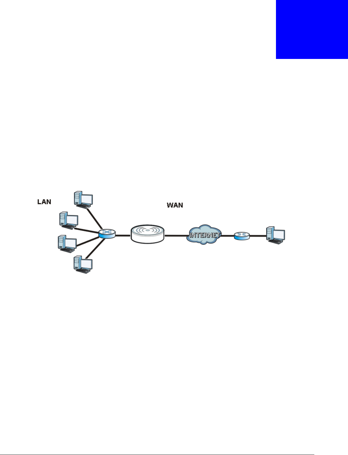
NBG6515 User’s Guide
101
CHAPTER 13
WAN
13.1 Overview
This chapter discusses the NBG’s WAN screens. Use these screens to configure your NBG for
Internet access.
A WAN (Wide Area Network) connection is an outside connection to another network or the
Internet. It connects your private networks such as a LAN (Local Area Network) and other
networks, so that a computer in one location can communicate with computers in other locations.
Figure 77 LAN and WAN
13.2 What You Can Do
•Use the Internet Connection screen (Section 13.4 on page 103) to enter your ISP information
and set how the computer acquires its IP, DNS and WAN MAC addresses.
•Use the Advanced screen (Section 13.5 on page 109) to enable multicasting, configure Windows
networking and bridge.
13.3 What You Need To Know
The information in this section can help you configure the screens for your WAN connection, as well
as enable/disable some advanced features of your NBG.
Router

Chapter 13 WAN
NBG6515 User’s Guide
102
13.3.1 Configuring Your Internet Connection
Encapsulation Method
Encapsulation is used to include data from an upper layer protocol into a lower layer protocol. To set
up a WAN connection to the Internet, you need to use the same encapsulation method used by your
ISP (Internet Service Provider). If your ISP offers a dial-up Internet connection using PPPoE (PPP
over Ethernet) or PPTP (Point-to-Point Tunneling Protocol), they should also provide a username
and password (and service name) for user authentication.
WAN IP Address
The WAN IP address is an IP address for the NBG, which makes it accessible from an outside
network. It is used by the NBG to communicate with other devices in other networks. It can be
static (fixed) or dynamically assigned by the ISP each time the NBG tries to access the Internet.
If your ISP assigns you a static WAN IP address, they should also assign you the subnet mask and
DNS server IP address(es) (and a gateway IP address if you use the Ethernet or ENET ENCAP
encapsulation method).
DNS Server Address Assignment
Use Domain Name System (DNS) to map a domain name to its corresponding IP address and vice
versa, for instance, the IP address of www.zyxel.com is 204.217.0.2. The DNS server is extremely
important because without it, you must know the IP address of a computer before you can access
it.
The NBG can get the DNS server addresses in the following ways.
1The ISP tells you the DNS server addresses, usually in the form of an information sheet, when you
sign up. If your ISP gives you DNS server addresses, manually enter them in the DNS server fields.
2If your ISP dynamically assigns the DNS server IP addresses (along with the NBG’s WAN IP
address), set the DNS server fields to get the DNS server address from the ISP.
WAN MAC Address
The MAC address screen allows users to configure the WAN port's MAC address by either using the
factory default or cloning the MAC address from a computer on your LAN. Choose Factory Default
to select the factory assigned default MAC Address.
Otherwise, click Clone the computer's MAC address - IP Address and enter the IP address of
the computer on the LAN whose MAC you are cloning. Once it is successfully configured, the
address will be copied to configuration file. It is recommended that you clone the MAC address prior
to hooking up the WAN Port.
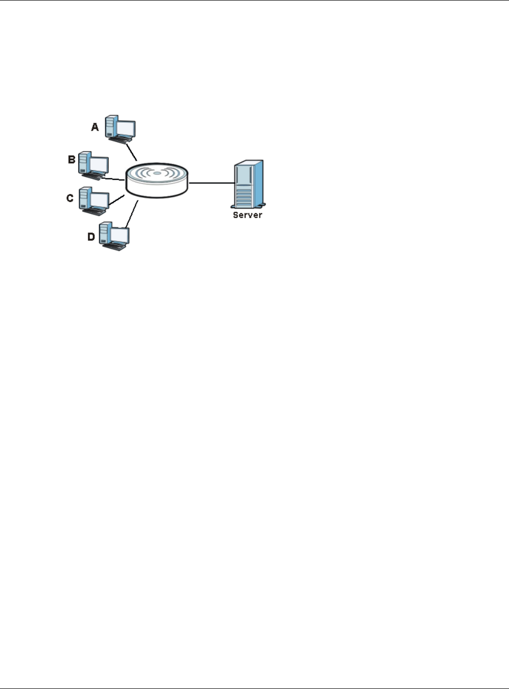
Chapter 13 WAN
NBG6515 User’s Guide
103
13.3.2 Multicast
Traditionally, IP packets are transmitted in one of either two ways - Unicast (1 sender - 1 recipient)
or Broadcast (1 sender - everybody on the network). Multicast delivers IP packets to a group of
hosts on the network - not everybody and not just 1.
Figure 78 Multicast Example
In the multicast example above, systems A and D comprise one multicast group. In multicasting,
the server only needs to send one data stream and this is delivered to systems A and D.
IGMP (Internet Group Multicast Protocol) is a network-layer protocol used to establish membership
in a multicast group - it is not used to carry user data. The NBG supports both IGMP version 1
(IGMP-v1) and IGMP version 2 (IGMP-v2).
At start up, the NBG queries all directly connected networks to gather group membership. After
that, the NBG periodically updates this information. IP multicasting can be enabled/disabled on the
NBG LAN and/or WAN interfaces in the Web Configurator (LAN; WAN). Select None to disable IP
multicasting on these interfaces.
13.4 Internet Connection
Use this screen to change your NBG’s Internet access settings. Click WAN from the Configuration
menu. The screen differs according to the encapsulation you choose.
13.4.1 Ethernet Encapsulation
This screen displays when you select Ethernet encapsulation.
Router
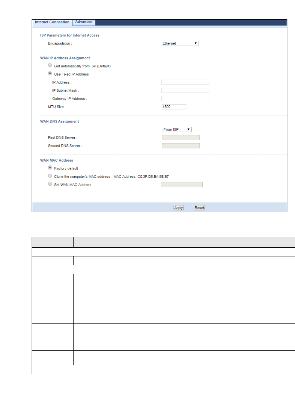
Chapter 13 WAN
NBG6515 User’s Guide
104
Figure 79 Network > WAN > Internet Connection: Ethernet Encapsulation
The following table describes the labels in this screen.
Table 51 Network > WAN > Internet Connection: Ethernet Encapsulation
LABEL DESCRIPTION
ISP Parameters for Internet Access
Encapsulation You must choose the Ethernet option when the WAN port is used as a regular Ethernet.
WAN IP Address Assignment
Get
automatically
from ISP
(Default)
Select this option If your ISP did not assign you a fixed IP address. This is the default
selection.
Use Fixed IP
Address
Select this option If the ISP assigned a fixed IP address.
IP Address Enter your WAN IP address in this field if you selected Use Fixed IP Address.
IP Subnet
Mask Enter the IP Subnet Mask in this field.
Gateway IP
Address Enter a Gateway IP Address (if your ISP gave you one) in this field.
MTU Size Enter the Maximum Transmission Unit (MTU) or the largest packet size per frame that your
NBG can receive and process.
WAN DNS Assignment

Chapter 13 WAN
NBG6515 User’s Guide
105
13.4.2 PPPoE Encapsulation
The NBG supports PPPoE (Point-to-Point Protocol over Ethernet). PPPoE is an IETF standard (RFC
2516) specifying how a personal computer (PC) interacts with a broadband modem (DSL, cable,
wireless, etc.) connection. The PPP over Ethernet option is for a dial-up connection using PPPoE.
For the service provider, PPPoE offers an access and authentication method that works with existing
access control systems (for example Radius).
One of the benefits of PPPoE is the ability to let you access one of multiple network services, a
function known as dynamic service selection. This enables the service provider to easily create and
offer new IP services for individuals.
Operationally, PPPoE saves significant effort for both you and the ISP or carrier, as it requires no
specific configuration of the broadband modem at the customer site.
By implementing PPPoE directly on the NBG (rather than individual computers), the computers on
the LAN do not need PPPoE software installed, since the NBG does that part of the task.
Furthermore, with NAT, all of the LANs’ computers will have access.
First DNS
Server
Second DNS
Server
Select From ISP if your ISP dynamically assigns DNS server information (and the NBG's
WAN IP address). The field to the right displays the (read-only) DNS server IP address that
the ISP assigns.
Select User-Defined if you have the IP address of a DNS server. Enter the DNS server's IP
address in the field to the right. If you chose User-Defined, but leave the IP address set to
0.0.0.0, User-Defined changes to None after you click Apply. If you set a second choice
to User-Defined, and enter the same IP address, the second User-Defined changes to
None after you click Apply.
Select None if you do not want to configure DNS servers. If you do not configure a DNS
server, you must know the IP address of a computer in order to access it.
WAN MAC
Address
The MAC address section allows users to configure the WAN port's MAC address by either
using the NBG’s MAC address, copying the MAC address from a computer on your LAN or
manually entering a MAC address.
Factory default Select Factory default to use the factory assigned default MAC Address.
Clone the
computer’s
MAC address -
IP Address
Select Clone the computer's MAC address - IP Address and enter the IP address of the
computer on the LAN whose MAC you are cloning.
Set WAN MAC
Address
Select this option and enter the MAC address you want to use.
Apply Click Apply to save your changes back to the NBG.
Reset Click Reset to begin configuring this screen afresh.
Table 51 Network > WAN > Internet Connection: Ethernet Encapsulation (continued)
LABEL DESCRIPTION
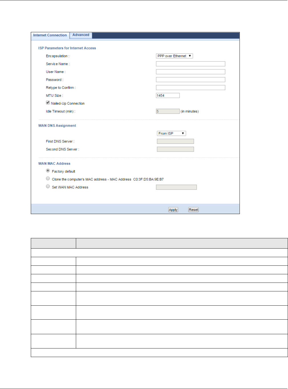
Chapter 13 WAN
NBG6515 User’s Guide
106
This screen displays when you select PPPoE encapsulation.
Figure 80 Network > WAN > Internet Connection: PPPoE Encapsulation
The following table describes the labels in this screen.
Table 52 Network > WAN > Internet Connection: PPPoE Encapsulation
LABEL DESCRIPTION
ISP Parameters for Internet Access
Encapsulation Select PPP over Ethernet if you connect to your Internet via dial-up.
Service Name
User Name Type the user name given to you by your ISP.
Password Type the password associated with the user name above.
Retype to
Confirm
Type your password again to make sure that you have entered is correctly.
MTU Size Enter the Maximum Transmission Unit (MTU) or the largest packet size per frame that your
NBG can receive and process.
Nailed-Up
Connection
Select Nailed-Up Connection if you do not want the connection to time out.
Idle Timeout
(min)
This value specifies the time in minutes that elapses before the router automatically
disconnects from the PPPoE server.
WAN DNS Assignment

Chapter 13 WAN
NBG6515 User’s Guide
107
13.4.3 PPTP Encapsulation
Point-to-Point Tunneling Protocol (PPTP) is a network protocol that enables secure transfer of data
from a remote client to a private server, creating a Virtual Private Network (VPN) using TCP/IP-
based networks.
PPTP supports on-demand, multi-protocol and virtual private networking over public networks, such
as the Internet.
Note: PPTP will be supported in the next firmware version.
First DNS Server
Second DNS
Server
Select From ISP if your ISP dynamically assigns DNS server information (and the NBG's
WAN IP address). The field to the right displays the (read-only) DNS server IP address
that the ISP assigns.
Select User-Defined if you have the IP address of a DNS server. Enter the DNS server's
IP address in the field to the right. If you chose User-Defined, but leave the IP address
set to 0.0.0.0, User-Defined changes to None after you click Apply. If you set a second
choice to User-Defined, and enter the same IP address, the second User-Defined
changes to None after you click Apply.
Select None if you do not want to configure DNS servers. If you do not configure a DNS
server, you must know the IP address of a computer in order to access it.
WAN MAC
Address
The MAC address section allows users to configure the WAN port's MAC address by using
the NBG’s MAC address, copying the MAC address from a computer on your LAN or
manually entering a MAC address.
Factory default Select Factory default to use the factory assigned default MAC Address.
Clone the
computer’s MAC
address - IP
Address
Select Clone the computer's MAC address - IP Address and enter the IP address of
the computer on the LAN whose MAC you are cloning.
Set WAN MAC
Address
Select this option and enter the MAC address you want to use.
Apply Click Apply to save your changes back to the NBG.
Reset Click Reset to begin configuring this screen afresh.
Table 52 Network > WAN > Internet Connection: PPPoE Encapsulation (continued)
LABEL DESCRIPTION
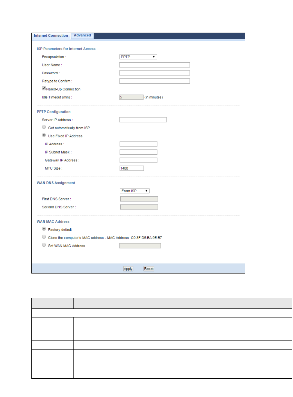
Chapter 13 WAN
NBG6515 User’s Guide
108
This screen displays when you select PPTP encapsulation.
Figure 81 Network > WAN > Internet Connection: PPTP Encapsulation
The following table describes the labels in this screen.
Table 53 Network > WAN > Internet Connection: PPTP Encapsulation
LABEL DESCRIPTION
ISP Parameters for Internet Access
Encapsulation To configure a PPTP client, you must configure the User Name and Password fields for a
PPP connection and the PPTP parameters for a PPTP connection.
User Name Type the user name given to you by your ISP.
Password Type the password associated with the User Name above.
Retype to
Confirm
Type your password again to make sure that you have entered is correctly.
Nailed-up
Connection
Select Nailed-Up Connection if you do not want the connection to time out.

Chapter 13 WAN
NBG6515 User’s Guide
109
13.5 Advanced WAN Screen
Use this screen to enable Multicast.
Note: The categories shown in this screen are independent of each other.
Idle Timeout
(min)
This value specifies the time in minutes that elapses before the NBG automatically
disconnects from the PPTP server.
PPTP Configuration
Server IP
Address
Type the IP address of the PPTP server.
Get
automatically
from ISP
Select this option If your ISP did not assign you a fixed IP address. This is the default
selection.
Use Fixed IP
Address
Select this option If the ISP assigned a fixed IP address.
IP Address Enter your WAN IP address in this field if you selected Use Fixed IP Address.
IP Subnet
Mask Your NBG will automatically calculate the subnet mask based on the IP address that you
assign. Unless you are implementing subnetting, use the subnet mask computed by the
NBG.
Gateway IP
Address Enter a Gateway IP Address (if your ISP gave you one) in this field.
MTU Size Enter the Maximum Transmission Unit (MTU) or the largest packet size per frame that your
NBG can receive and process.
WAN DNS Assignment
First DNS
Server
Second DNS
Server
Select From ISP if your ISP dynamically assigns DNS server information (and the NBG's
WAN IP address). The field to the right displays the (read-only) DNS server IP address that
the ISP assigns.
Select User-Defined if you have the IP address of a DNS server. Enter the DNS server's IP
address in the field to the right. If you chose User-Defined, but leave the IP address set to
0.0.0.0, User-Defined changes to None after you click Apply. If you set a second choice
to User-Defined, and enter the same IP address, the second User-Defined changes to
None after you click Apply.
Select None if you do not want to configure DNS servers. If you do not configure a DNS
server, you must know the IP address of a computer in order to access it.
WAN MAC
Address
The MAC address section allows users to configure the WAN port's MAC address by either
using the NBG’s MAC address, copying the MAC address from a computer on your LAN or
manually entering a MAC address.
Factory default Select Factory default to use the factory assigned default MAC Address.
Clone the
computer’s
MAC address -
IP Address
Select Clone the computer's MAC address - IP Address and enter the IP address of the
computer on the LAN whose MAC you are cloning.
Set WAN MAC
Address
Select this option and enter the MAC address you want to use.
Apply Click Apply to save your changes back to the NBG.
Reset Click Reset to begin configuring this screen afresh.
Table 53 Network > WAN > Internet Connection: PPTP Encapsulation (continued)
LABEL DESCRIPTION
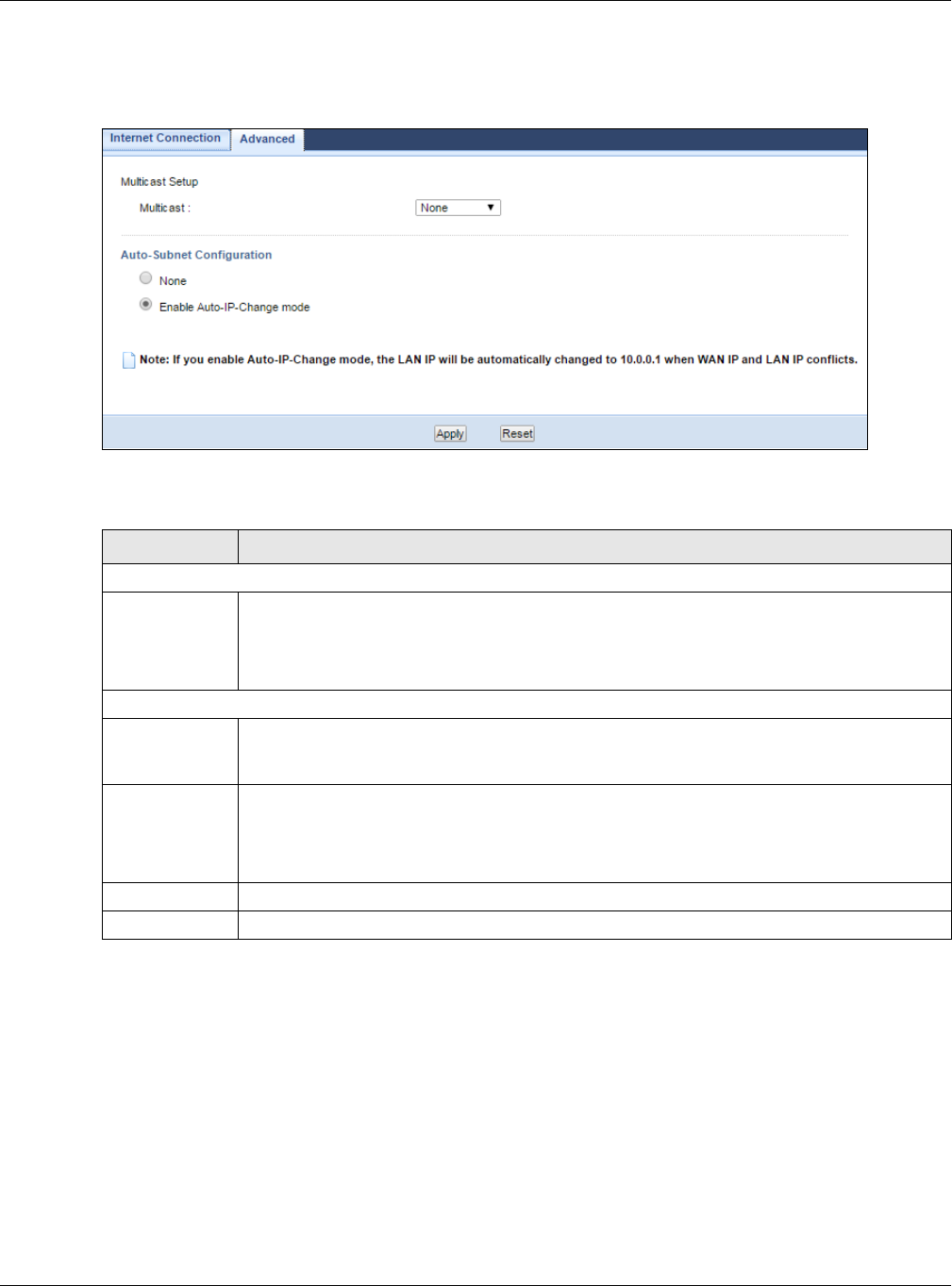
Chapter 13 WAN
NBG6515 User’s Guide
110
To change your NBG’s advanced WAN settings, click Network > WAN > Advanced. The screen
appears as shown.
Figure 82 Network > WAN > Advanced
The following table describes the labels in this screen.
Table 54 Network > WAN > Advanced
LABEL DESCRIPTION
Multicast Setup
Multicast Select IGMPv1/v2 to enable multicasting. This applies to traffic routed from the WAN to
the LAN.
Select None to disable this feature. This may cause incoming traffic to be dropped or sent
to all connected network devices.
Auto-Subnet Configuration
None Select this option to have the NBG do nothing when it gets a WAN IP address in the range of
192.168.x.y (where x and y are from zero to nine) or in the same subnet as the LAN IP
address.
Enable Auto-IP-
Change mode
Select this option to have the NBG change its LAN IP address to 10.0.0.1 or 192.168.1.1
accordingly when the NBG gets a dynamic WAN IP address in the same subnet as the LAN IP
address 192.168.1.1 or 10.0.0.1.
The NAT, DHCP server and firewall functions on the NBG are still available in thismode.
Apply Click Apply to save your changes back to the NBG.
Reset Click Reset to begin configuring this screen afresh.

NBG6515 User’s Guide
111
CHAPTER 14
LAN
14.1 Overview
This chapter describes how to configure LAN settings.
A Local Area Network (LAN) is a shared communication system to which many computers are
attached. A LAN is a computer network limited to the immediate area, usually the same building or
floor of a building. The LAN screens can help you configure a LAN DHCP server, manage IP
addresses, and partition your physical network into logical networks.
Figure 83 LAN Example
The LAN screens can help you manage IP addresses.
14.2 What You Can Do
•Use the IP screen (Section 14.4 on page 112) to change the IP address for your NBG.
14.3 What You Need To Know
The actual physical connection determines whether the NBG ports are LAN or WAN ports. There are
two separate IP networks, one inside the LAN network and the other outside the WAN network as
shown next.
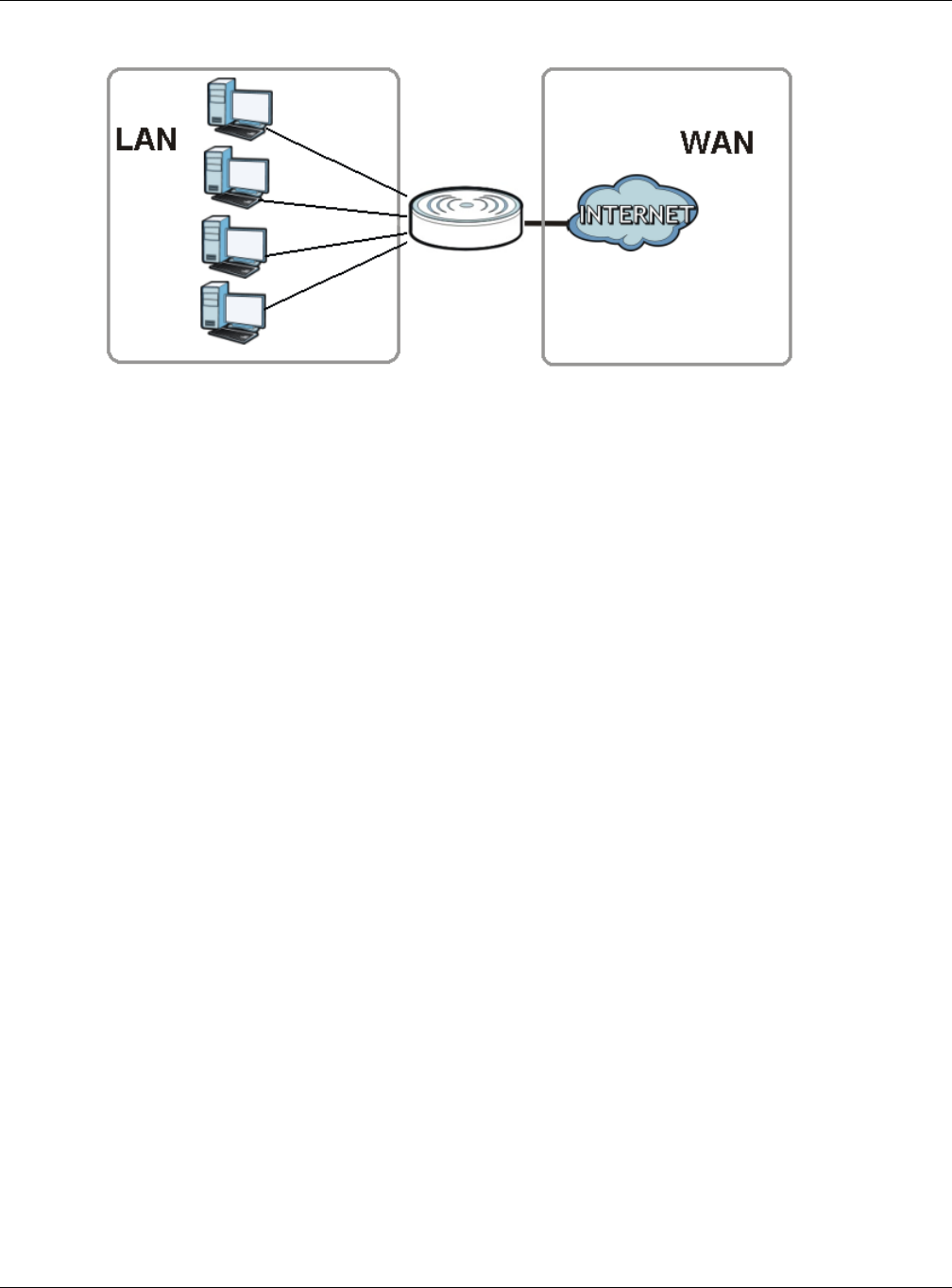
Chapter 14 LAN
NBG6515 User’s Guide
112
Figure 84 LAN and WAN IP Addresses
The LAN parameters of the NBG are preset in the factory with the following values:
• IP address of 192.168.1.1 with subnet mask of 255.255.255.0 (24 bits)
• DHCP server enabled with 32 client IP addresses starting from 192.168.1.33.
These parameters should work for the majority of installations. If your ISP gives you explicit DNS
server address(es), read the embedded Web Configurator help regarding what fields need to be
configured.
14.3.1 IP Pool Setup
The NBG is pre-configured with a pool of 32 IP addresses starting from 192.168.1.33 to
192.168.1.64. This configuration leaves 31 IP addresses (excluding the NBG itself) in the lower
range (192.168.1.2 to 192.168.1.32) for other server computers, for instance, servers for mail,
FTP, TFTP, web, etc., that you may have.
14.3.2 LAN TCP/IP
The NBG has built-in DHCP server capability that assigns IP addresses and DNS servers to systems
that support DHCP client capability.
14.3.3 IP Alias
IP alias allows you to partition a physical network into different logical networks over the same
Ethernet interface. The NBG supports three logical LAN interfaces via its single physical Ethernet
interface with the NBG itself as the gateway for each LAN network.
14.4 LAN IP Screen
Use this screen to change the IP address for your NBG. Click Network > LAN > IP.
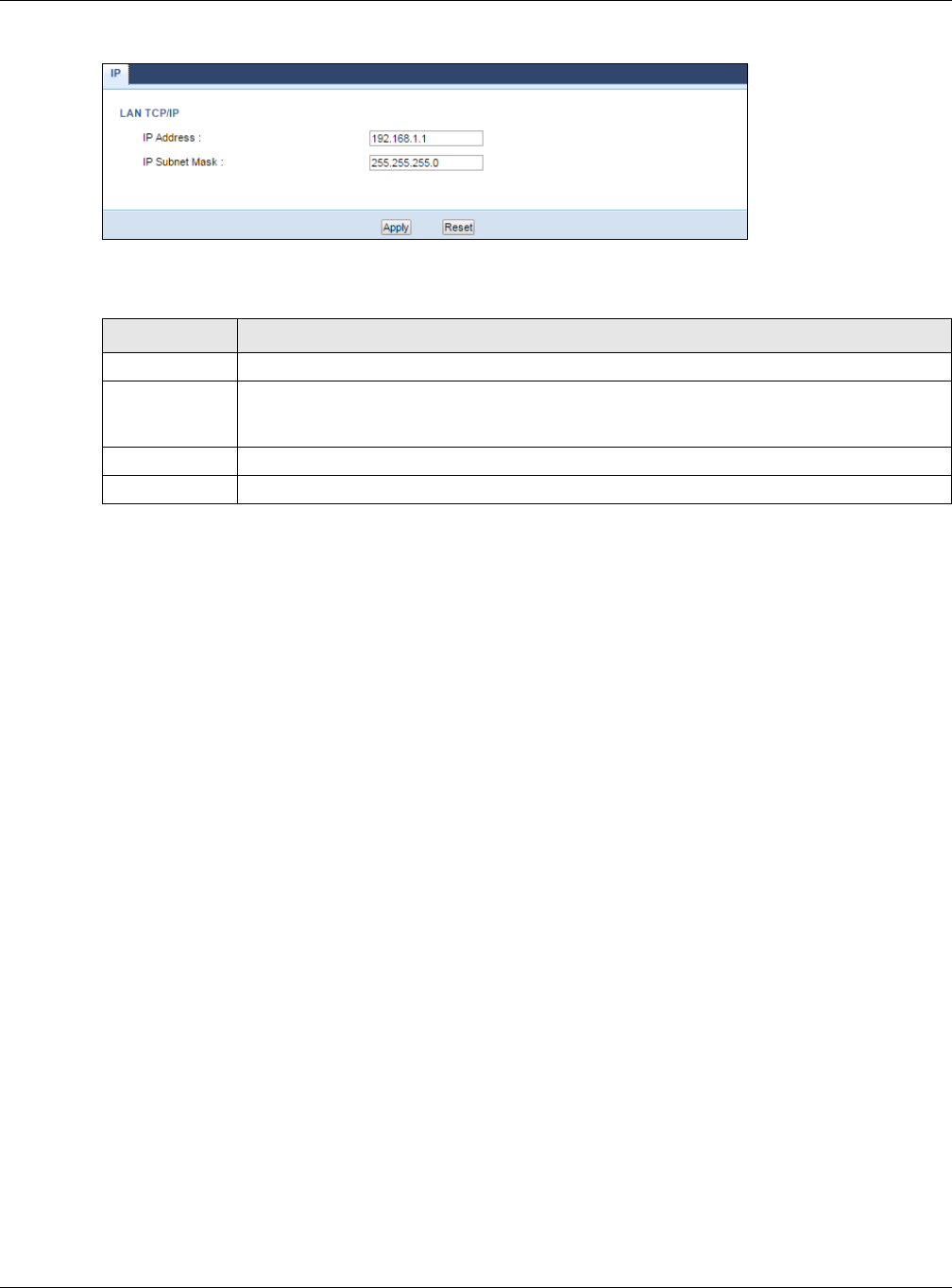
Chapter 14 LAN
NBG6515 User’s Guide
113
Figure 85 Network > LAN > IP
The following table describes the labels in this screen.
Table 55 Network > LAN > IP
LABEL DESCRIPTION
IP Address Type the IP address of your NBG in dotted decimal notation.
IP Subnet Mask The subnet mask specifies the network number portion of an IP address. Your NBG will
automatically calculate the subnet mask based on the IP address that you assign. Unless
you are implementing subnetting, use the subnet mask computed by the NBG.
Apply Click Apply to save your changes back to the NBG.
Reset Click Reset to begin configuring this screen afresh.
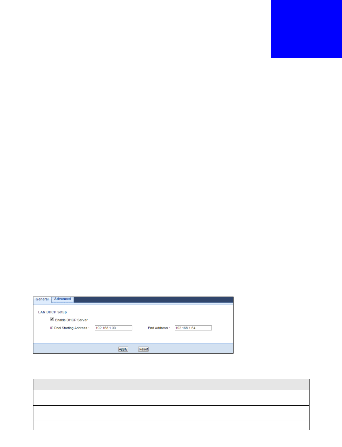
NBG6515 User’s Guide
114
CHAPTER 15
DHCP Server
15.1 Overview
DHCP (Dynamic Host Configuration Protocol, RFC 2131 and RFC 2132) allows individual clients to
obtain TCP/IP configuration at start-up from a server. You can configure the NBG’s LAN as a DHCP
server or disable it. When configured as a server, the NBG provides the TCP/IP configuration for the
clients. If DHCP service is disabled, you must have another DHCP server on your LAN, or else the
computer must be manually configured.
15.2 What You Can Do
•Use the General (Section 15.3 on page 114) screen to enable the DHCP server.
•Use the Advanced (Section 15.4 on page 115) screen to assign IP addresses on the LAN to
specific individual computers based on their MAC Addresses.
15.3 General Screen
Use this screen to enable the DHCP server. Click Network > DHCP Server. The following screen
displays.
Figure 86 Network > DHCP Server > General
The following table describes the labels in this screen.
Table 56 Network > DHCP Server > General
LABEL DESCRIPTION
Enable DHCP
Server
Select this check box to activate the DHCP for LAN.
IP Pool Starting
Address
This field specifies the first of the contiguous addresses in the IP address pool for LAN.
End Address This field specifies the last of the contiguous addresses in the IP address pool for LAN.
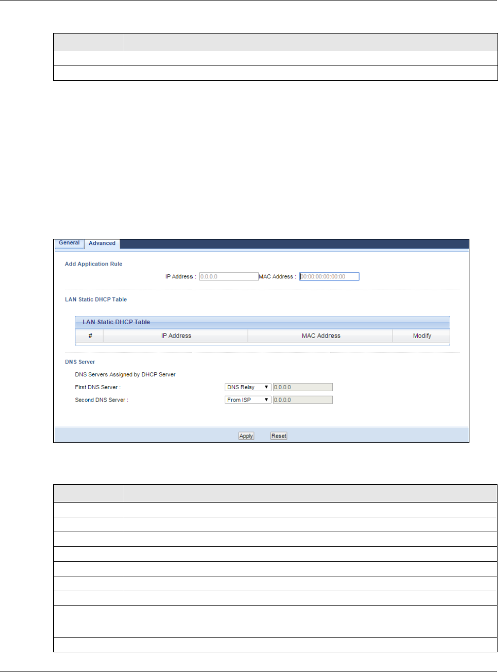
Chapter 15 DHCP Server
NBG6515 User’s Guide
115
15.4 Advanced Screen
This screen allows you to assign IP addresses on the LAN to specific individual computers based on
their MAC addresses. You can also use this screen to configure the DNS server information that the
NBG sends to the DHCP clients.
To change your NBG’s static DHCP settings, click Network > DHCP Server > Advanced. The
following screen displays.
Figure 87 Network > DHCP Server > Advanced
The following table describes the labels in this screen.
Apply Click Apply to save your changes back to the NBG.
Reset Click Reset to begin configuring this screen afresh.
Table 56 Network > DHCP Server > General (continued)
LABEL DESCRIPTION
Table 57 Network > DHCP Server > Advanced
LABEL DESCRIPTION
Add Application Rule
IP Address Type the LAN IP address based on the MAC address in dotted decimal notation.
MAC Address Type the MAC address (with colons) you want to assign to your NBG
LAN Static DHCP Table
# This is the index number of the static IP table entry (row).
IP Address Type the LAN IP address of a computer on your LAN.
MAC Address Type the MAC address (with colons) of a computer on your LAN.
Modify Click the Edit icon to open the edit screen where you can modify an IP address.
Click the Delete icon to remove an IP address.
DNS Server

Chapter 15 DHCP Server
NBG6515 User’s Guide
116
DNS Servers
Assigned by
DHCP Server
The NBG passes a DNS (Domain Name System) server IP address (in the order you specify
here) to the DHCP clients. The NBG only passes this information to the LAN DHCP clients
when you select the Enable DHCP Server check box. When you clear the Enable DHCP
Server check box, DHCP service is disabled and you must have another DHCP sever on your
LAN, or else the computers must have their DNS server addresses manually configured.
First DNS
Server
Second DNS
Server
Select From ISP if your ISP dynamically assigns DNS server information (and the NBG's
WAN IP address). The field to the right displays the (read-only) DNS server IP address that
the ISP assigns.
Select User-Defined if you have the IP address of a DNS server. Enter the DNS server's IP
address in the field to the right. If you chose User-Defined, but leave the IP address set to
0.0.0.0, User-Defined changes to None after you click Apply. If you set a second choice to
User-Defined, and enter the same IP address, the second User-Defined changes to None
after you click Apply.
Select DNS Relay to have the NBG act as a DNS proxy. The NBG's LAN IP address displays
in the field to the right (read-only). The NBG tells the DHCP clients on the LAN that the NBG
itself is the DNS server. When a computer on the LAN sends a DNS query to the NBG, the
NBG forwards the query to the NBG's system DNS server (configured in the WAN >
Internet Connection screen) and relays the response back to the computer. You can only
select DNS Relay for one of the three servers; if you select DNS Relay for a second or
third DNS server, that choice changes to None after you click Apply.
Select None if you do not want to configure DNS servers. If you do not configure a DNS
server, you must know the IP address of a computer in order to access it.
Apply Click Apply to save your changes back to the NBG.
Reset Click Reset to begin configuring this screen afresh.
Table 57 Network > DHCP Server > Advanced (continued)
LABEL DESCRIPTION
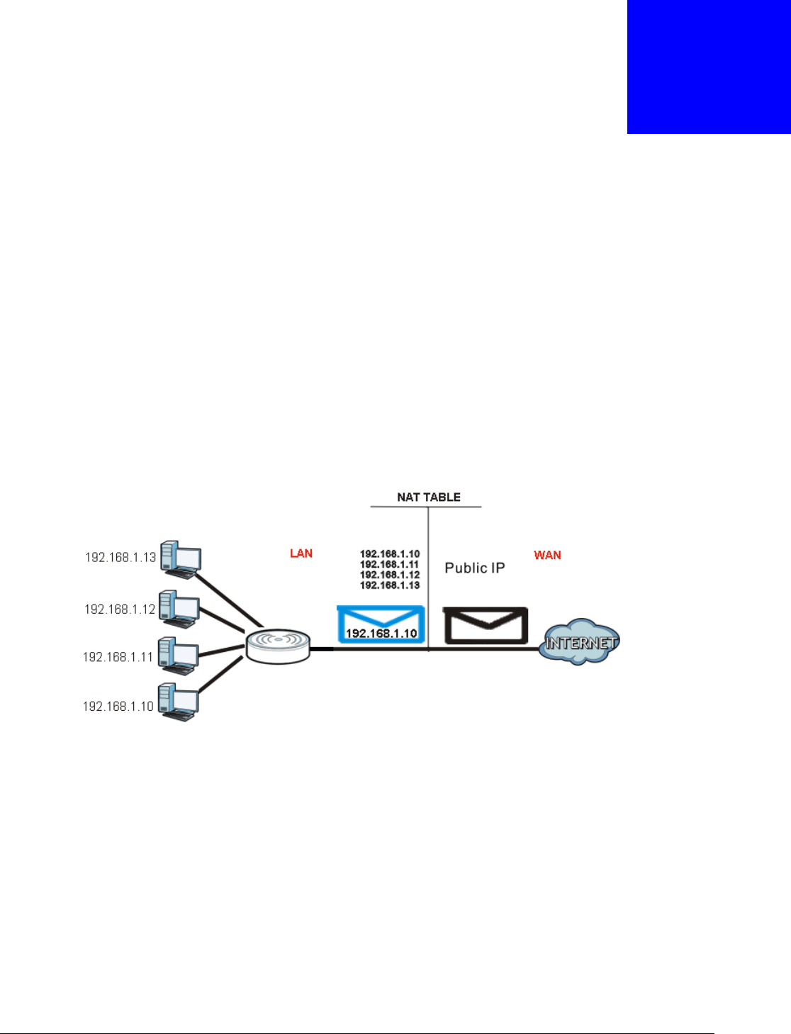
NBG6515 User’s Guide
117
CHAPTER 16
Network Address Translation (NAT)
16.1 Overview
NAT (Network Address Translation - NAT, RFC 1631) is the translation of the IP address of a host in
a packet. For example, the source address of an outgoing packet, used within one network is
changed to a different IP address known within another network.
Each packet has two addresses – a source address and a destination address. For outgoing packets,
NAT maps private (local) IP addresses to globally unique ones required for communication with
hosts on other networks. It replaces the original IP source address in each packet and then
forwards it to the Internet. The NBG keeps track of the original addresses and port numbers so
incoming reply packets can have their original values restored. The following figure illustrates this.
Figure 88 NAT Example
For more information on IP address translation, refer to RFC 1631, The IP Network Address
Translator (NAT).
16.2 What You Can Do
•Use the General screen (Section 16.3 on page 118) to enable NAT and set a default server.
•Use the Application screen (Section 16.4 on page 118) o forward incoming service requests to
the server(s) on your local network.
•Use the Advanced screen (Section 16.5 on page 120) to change your NBG’s trigger port
settings.
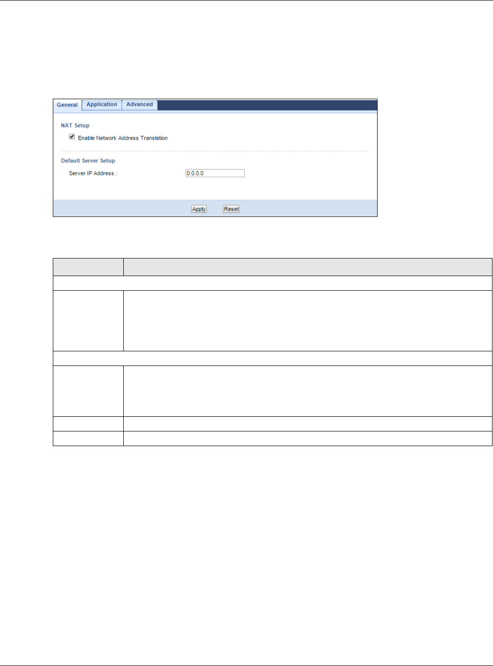
Chapter 16 Network Address Translation (NAT)
NBG6515 User’s Guide
118
16.3 General NAT Screen
Use this screen to enable NAT and set a default server. Click Network > NAT > General to open
the following screen.
Figure 89 Network > NAT > General
The following table describes the labels in this screen.
16.4 NAT Application Screen
Use the Application screen to forward incoming service requests to the server(s) on your local
network. You may enter a single port number or a range of port numbers to be forwarded, and the
local IP address of the desired server. The port number identifies a service; for example, web
service is on port 80 and FTP on port 21. In some cases, such as for unknown services or where one
server can support more than one service (for example both FTP and web service), it might be
better to specify a range of port numbers.
In addition to the servers for specified services, NAT supports a default server. A service request
that does not have a server explicitly designated for it is forwarded to the default server. If the
default is not defined, the service request is simply discarded.
Table 58 Network > NAT > General
LABEL DESCRIPTION
NAT Setup
Enable Network
Address
Translation
Network Address Translation (NAT) allows the translation of an Internet protocol address
used within one network (for example a private IP address used in a local network) to a
different IP address known within another network (for example a public IP address used on
the Internet).
Select the check box to enable NAT.
Default Server Setup
Server IP
Address In addition to the servers for specified services, NAT supports a default server. A default
server receives packets from ports that are not specified in the Application screen.
If you do not assign a Default Server IP address, the NBG discards all packets received
for ports that are not specified in the Application screen or remote management.
Apply Click Apply to save your changes back to the NBG.
Reset Click Reset to begin configuring this screen afresh.
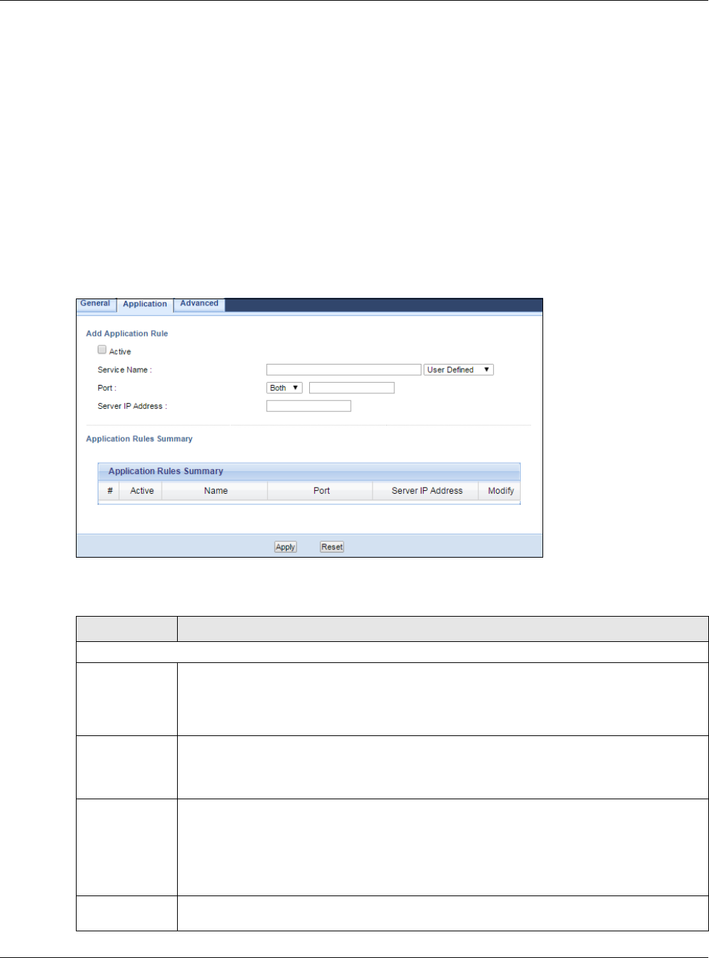
Chapter 16 Network Address Translation (NAT)
NBG6515 User’s Guide
119
Note: Many residential broadband ISP accounts do not allow you to run any server
processes (such as a Web or FTP server) from your location. Your ISP may
periodically check for servers and may suspend your account if it discovers any
active services at your location. If you are unsure, refer to your ISP.
Port forwarding allows you to define the local servers to which the incoming services will be
forwarded. To change your NBG’s port forwarding settings, click Network > NAT > Application.
The screen appears as shown.
Note: If you do not assign a Default Server IP address in the NAT > General screen,
the NBG discards all packets received for ports that are not specified in this screen
or remote management.
Refer to Appendix E on page 232 for port numbers commonly used for particular services.
Figure 90 Network > NAT > Application
The following table describes the labels in this screen.
Table 59 Network > NAT > Application
LABEL DESCRIPTION
Add Application Rule
Active Select the check box to enable this rule and the requested service can be forwarded to the
host with a specified internal IP address.
Clear the checkbox to disallow forwarding of these ports to an inside server without having
to delete the entry.
Service Name Type a name (of up to 31 printable characters) to identify this rule in the first field next to
Service Name. Otherwise, select a predefined service in the second field next to Service
Name. The predefined service name and port number(s) will display in the Service Name
and Port fields.
Port Type a port number(s) to define the service to be forwarded to the specified server.
To specify a range of ports, enter a hyphen (-) between the first port and the last port, such
as 10-20.
To specify two or more non-consecutive port numbers, separate them by a comma without
spaces, such as 123,567.
Server IP
Address
Type the IP address of the server on your LAN that receives packets from the port(s)
specified in the Port field.

Chapter 16 Network Address Translation (NAT)
NBG6515 User’s Guide
120
16.5 NAT Advanced Screen
Some services use a dedicated range of ports on the client side and a dedicated range of ports on
the server side. With regular port forwarding you set a forwarding port in NAT to forward a service
(coming in from the server on the WAN) to the IP address of a computer on the client side (LAN).
The problem is that port forwarding only forwards a service to a single LAN IP address. In order to
use the same service on a different LAN computer, you have to manually replace the LAN
computer's IP address in the forwarding port with another LAN computer's IP address.
Trigger port forwarding solves this problem by allowing computers on the LAN to dynamically take
turns using the service. The NBG records the IP address of a LAN computer that sends traffic to the
WAN to request a service with a specific port number and protocol (a "trigger" port). When the
NBG's WAN port receives a response with a specific port number and protocol ("incoming" port),
the NBG forwards the traffic to the LAN IP address of the computer that sent the request. After that
computer’s connection for that service closes, another computer on the LAN can use the service in
the same manner. This way you do not need to configure a new IP address each time you want a
different LAN computer to use the application.
To change your NBG’s trigger port settings, click Network > NAT > Advanced. The screen
appears as shown.
Note: Only one LAN computer can use a trigger port (range) at a time.
Application Rules Summary
#This is the number of an individual port forwarding server entry.
Active This icon is turned on when the rule is enabled.
Name This field displays a name to identify this rule.
Port This field displays the port number(s).
Server IP
Address
This field displays the inside IP address of the server.
Modify Click the Edit icon to display and modify an existing rule setting in the fields under Add
Application Rule.
Click the Remove icon to delete a rule.
Apply Click Apply to save your changes back to the NBG.
Reset Click Reset to begin configuring this screen afresh.
Table 59 Network > NAT > Application (continued)
LABEL DESCRIPTION
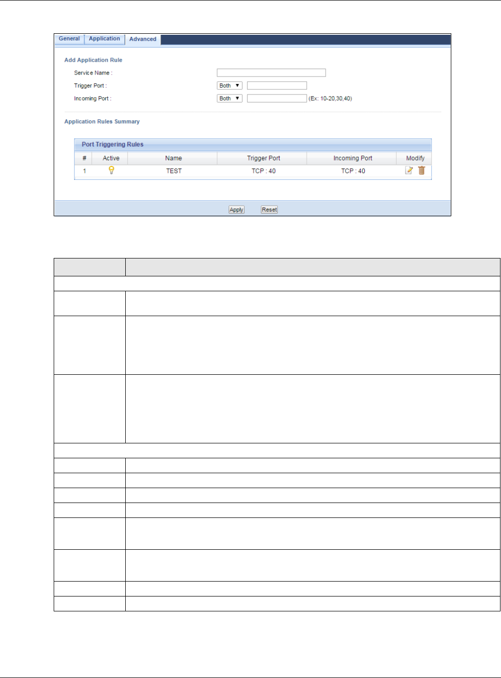
Chapter 16 Network Address Translation (NAT)
NBG6515 User’s Guide
121
Figure 91 Network > NAT > Advanced
The following table describes the labels in this screen.
16.5.1 Trigger Port Forwarding Example
The following is an example of trigger port forwarding.
Table 60 Network > NAT > Advanced
LABEL DESCRIPTION
Add Application Rule
Service Name Type a unique name (up to 15 characters) for identification purposes. All characters are
permitted - including spaces.
Trigger Port The trigger port is a port (or a range of ports) that causes (or triggers) the NBG to record
the IP address of the LAN computer that sent the traffic to a server on the WAN.
Select the transport layer protocol used for the service. Choices are TCP, UDP, or Both.
Type a port number or a range of port numbers.
Incoming Port Incoming is a port (or a range of ports) that a server on the WAN uses when it sends out a
particular service. The NBG forwards the traffic with this port (or range of ports) to the
client computer on the LAN that requested the service.
Select the transport layer protocol used for the service. Choices are TCP, UDP, or Both.
Type a port number or a range of port numbers.
Application Rules Summary
#This is the rule index number (read-only).
Active This icon is turned on when the rule is enabled.
Name This field displays a name to identify this rule.
Trigger Port This field displays the protocol and the port number or a range of port numbers.
Incoming Port This field displays the protocol and the port number or a range of port numbers.
Modify Click the Edit icon to edit the port triggering rule.
Click the Delete icon to delete an existing rule.
Apply Click Apply to save your changes back to the NBG.
Reset Click Reset to begin configuring this screen afresh.
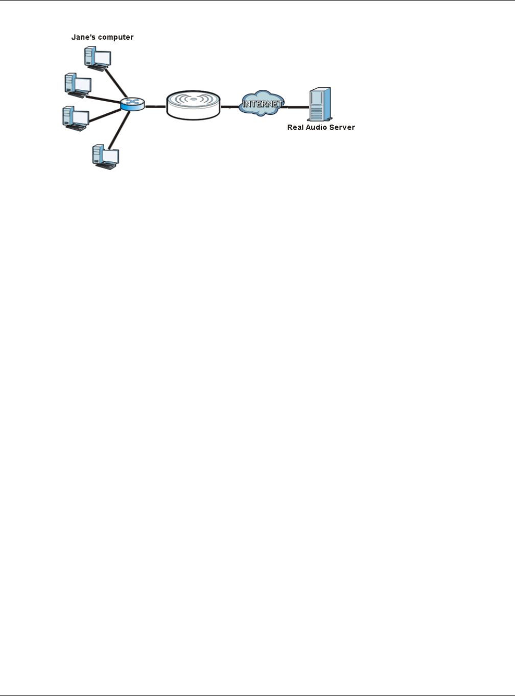
Chapter 16 Network Address Translation (NAT)
NBG6515 User’s Guide
122
Figure 92 Trigger Port Forwarding Process: Example
1Jane requests a file from the Real Audio server (port 7070).
2Port 7070 is a “trigger” port and causes the NBG to record Jane’s computer IP address. The NBG
associates Jane's computer IP address with the "incoming" port range of 6970-7170.
3The Real Audio server responds using a port number ranging between 6970-7170.
4The NBG forwards the traffic to Jane’s computer IP address.
5Only Jane can connect to the Real Audio server until the connection is closed or times out. The NBG
times out in three minutes with UDP (User Datagram Protocol), or two hours with TCP/IP (Transfer
Control Protocol/Internet Protocol).
16.5.2 Two Points To Remember About Trigger Ports
1Trigger events only happen on data that is going coming from inside the NBG and going to the
outside.
2If an application needs a continuous data stream, that port (range) will be tied up so that another
computer on the LAN can’t trigger it.
Router
Router
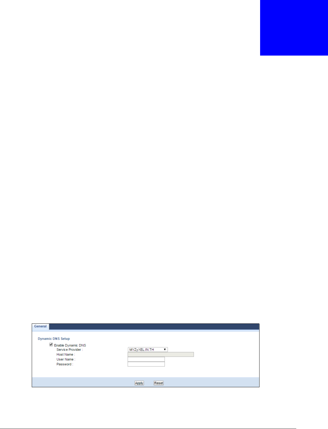
NBG6515 User’s Guide
123
CHAPTER 17
Dynamic DNS
17.1 Overview
Dynamic DNS (DDNS) services let you use a domain name with a dynamic IP address.
17.2 What You Can Do
Use the Dynamic DNS screen (Section 17.4 on page 123) to enable DDNS and configure the DDNS
settings on the NBG.
17.3 What You Need To Know
Dynamic DNS allows you to update your current dynamic IP address with one or many dynamic
DNS services so that anyone can contact you (in NetMeeting, CU-SeeMe, etc.). You can also access
your FTP server or Web site on your own computer using a domain name (for instance
myhost.dhs.org, where myhost is a name of your choice) that will never change instead of using an
IP address that changes each time you reconnect. Your friends or relatives will always be able to
call you even if they don't know your IP address.
17.4 Dynamic DNS Screen
To change your NBG’s DDNS, click Network > DDNS. The screen appears as shown.
Figure 93 Network > DDNS

Chapter 17 Dynamic DNS
NBG6515 User’s Guide
124
The following table describes the labels in this screen.
Table 61 Network > DDNS
LABEL DESCRIPTION
Enable
Dynamic DNS
Select this check box to use dynamic DNS.
Service
Provider
Select the name of your Dynamic DNS service provider.
Host Name Enter a host names in the field provided. You can specify up to two host names in the field
separated by a comma (",").
User Name Enter your user name.
Password Enter the password assigned to you.
Apply Click Apply to save your changes back to the NBG.
Reset Click Reset to begin configuring this screen afresh.
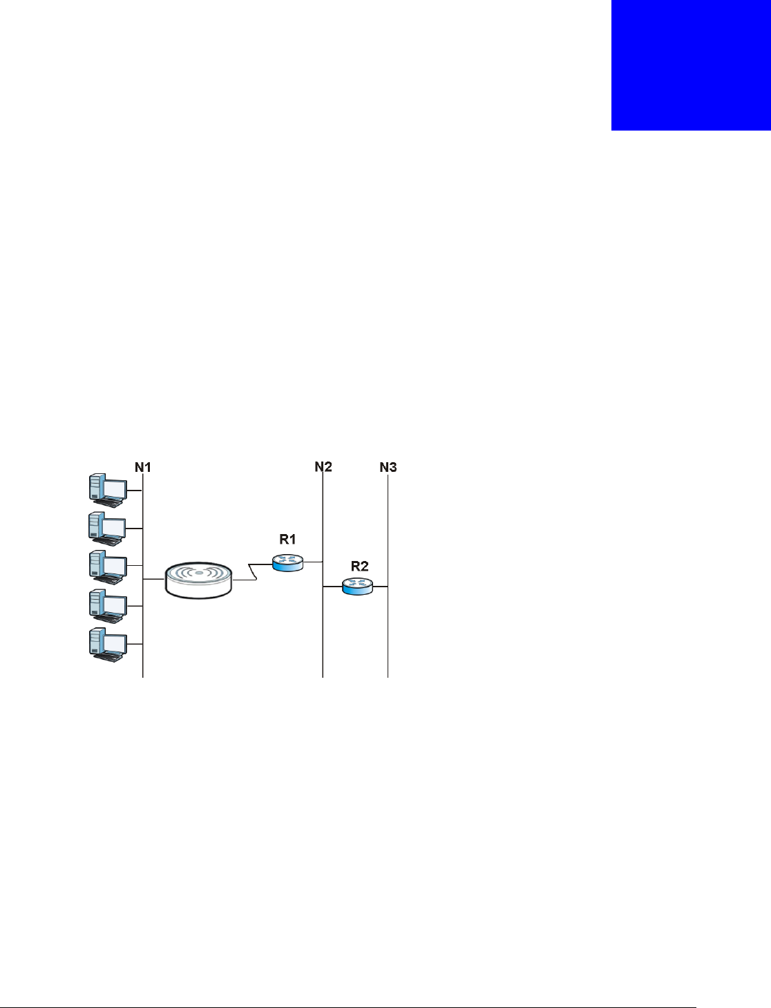
NBG6515 User’s Guide
125
CHAPTER 18
Static Route
18.1 Overview
This chapter shows you how to configure static routes for your NBG.
Each remote node specifies only the network to which the gateway is directly connected, and the
NBG has no knowledge of the networks beyond. For instance, the NBG knows about network N2 in
the following figure through remote node Router 1. However, the NBG is unable to route a packet to
network N3 because it doesn't know that there is a route through the same remote node Router 1
(via gateway Router 2). The static routes are for you to tell the NBG about the networks beyond the
remote nodes.
Figure 94 Example of Static Routing Topology
18.2 What You Can Do
Use the IP Static Route screen (Section 18.3 on page 125) to view, add and delete routes.
18.3 IP Static Route Screen
Click Network > Static Route to open the IP Static Route screen.
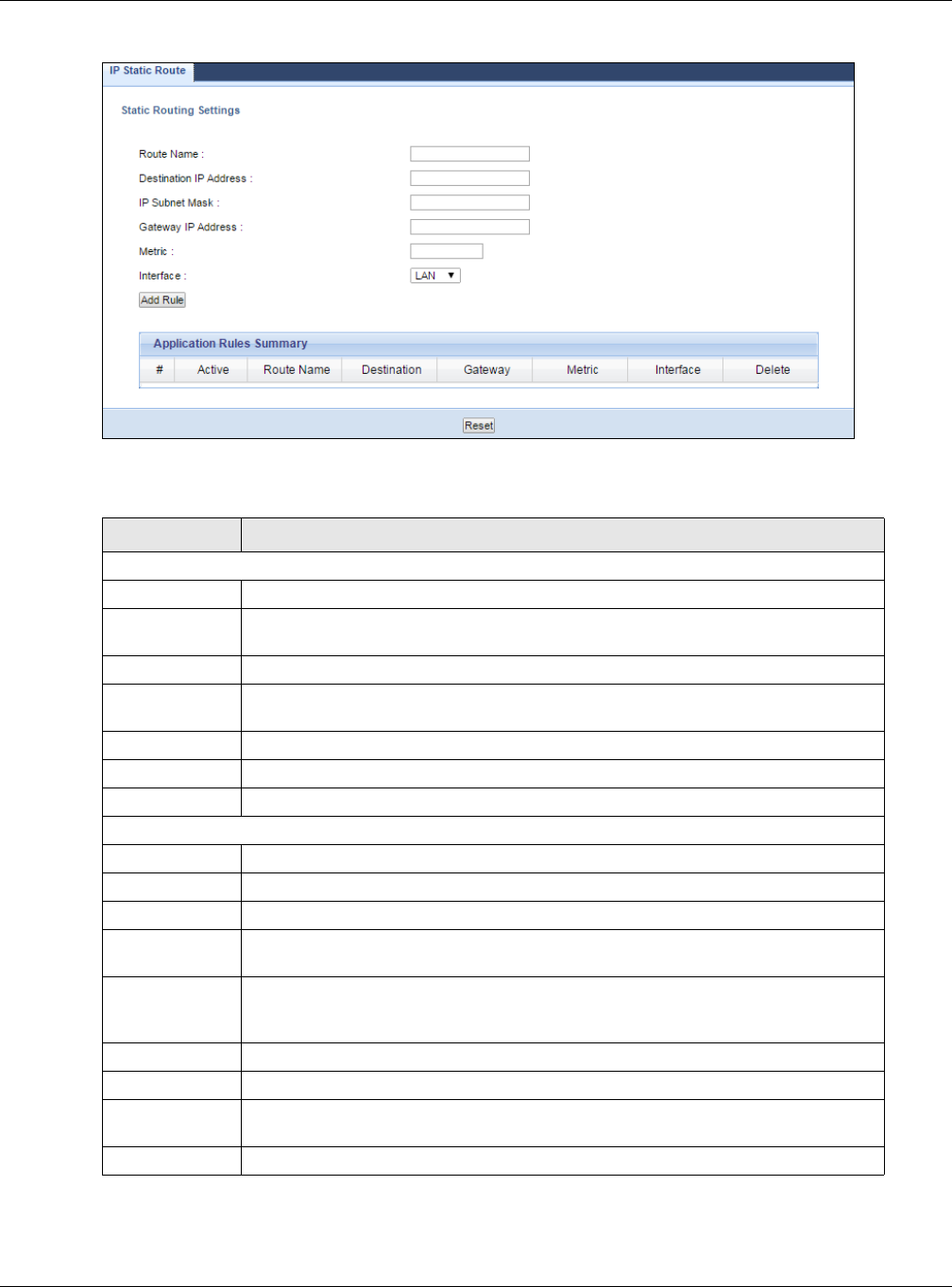
Chapter 18 Static Route
NBG6515 User’s Guide
126
Figure 95 Network > Static Route
The following table describes the labels in this screen.
Table 62 Network > Static Route
LABEL DESCRIPTION
Static Routing Settings
Route Name Enter a the name that describes or identifies this route.
Destination IP
Address
Enter the IP network address of the final destination.
IP Subnet Mask This is the subnet to which the route’s final destination belongs.
Gateway IP
Address
Enter the the IP address of the gateway.
Metric Assign a number to identify the route.
Interface Select the NBG port types. The port types are WAN and LAN.
Add Rule Click this to add the IP static route.
Application Rules Summary
#This is the number of an individual static route.
Active The rules are always on and this is indicated by the icon.
Route Name This is the name that describes or identifies this route.
Destination This parameter specifies the IP network address of the final destination. Routing is
always based on network number.
Gateway This is the IP address of the gateway. The gateway is a router or switch on the
same network segment as the device's LAN or WAN port. The gateway helps
forward packets to their destinations.
Metric This is the number assigned to the route.
Interface This displays the NBG port types. The port types are WAN and LAN.
Delete Click the Delete icon to remove a static route from the NBG. A window displays
asking you to confirm that you want to delete the route.
Reset Click Reset to begin configuring this screen afresh.
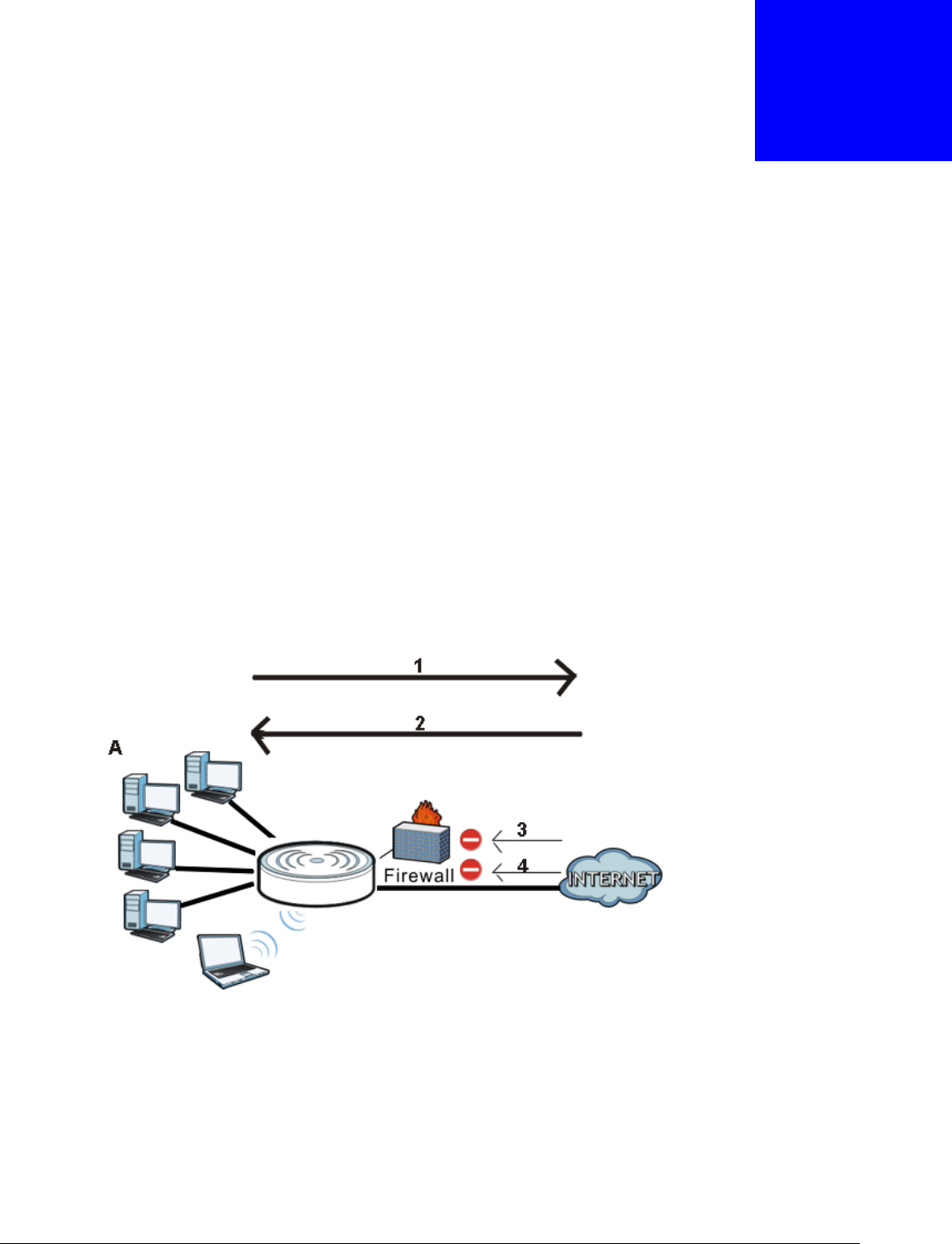
NBG6515 User’s Guide
127
CHAPTER 19
Firewall
19.1 Overview
This chapter shows you how to enable and configure the firewall that protects your NBG and your
LAN from unwanted or malicious traffic.
Enable the firewall to protect your LAN computers from attacks by hackers on the Internet and
control access between the LAN and WAN. By default the firewall:
• allows traffic that originates from your LAN computers to go to all of the networks.
• blocks traffic that originates on the other networks from going to the LAN.
The following figure illustrates the default firewall action. User A can initiate an IM (Instant
Messaging) session from the LAN to the WAN (1). Return traffic for this session is also allowed (2).
However other traffic initiated from the WAN is blocked (3 and 4).
Figure 96 Default Firewall Action
19.2 What You Can Do
•Use the General (Section 19.4 on page 128) screen to enable or disable the NBG’s firewall.
•Use the MAC Filtering Rule screen (Section 19.5 on page 129) to configure the NBG to block
access to devices or block the devices from accessing the NBG.
•Use the IP Filtering Rule screen (Section 19.6 on page 130) to configure the NBG to block
access to devices or block the devices from accessing the NBG.
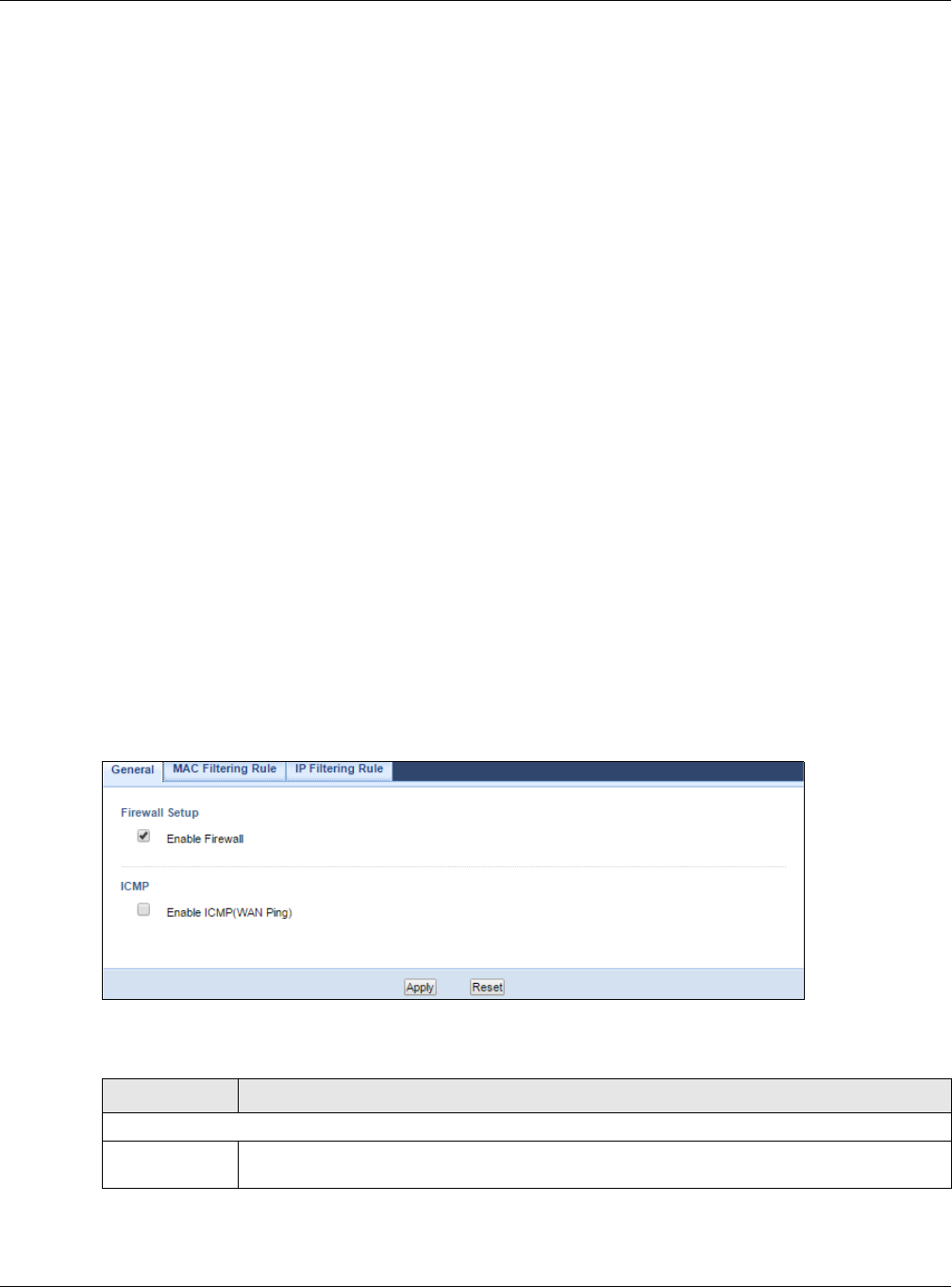
Chapter 19 Firewall
NBG6515 User’s Guide
128
19.3 What You Need To Know
The NBG’s firewall feature physically separates the LAN and the WAN and acts as a secure gateway
for all data passing between the networks.
It is designed to protect against Denial of Service (DoS) attacks when activated (click the General
tab under Firewall and then click the Enable Firewall check box). The NBG's purpose is to allow a
private Local Area Network (LAN) to be securely connected to the Internet. The NBG can be used to
prevent theft, destruction and modification of data, as well as log events, which may be important
to the security of your network.
The NBG is installed between the LAN and a broadband modem connecting to the Internet. This
allows it to act as a secure gateway for all data passing between the Internet and the LAN.
The NBG has one Ethernet WAN port and four Ethernet LAN ports, which are used to physically
separate the network into two areas.The WAN (Wide Area Network) port attaches to the broadband
(cable or DSL) modem to the Internet.
The LAN (Local Area Network) port attaches to a network of computers, which needs security from
the outside world. These computers will have access to Internet services such as e-mail, FTP and
the World Wide Web. However, "inbound access" is not allowed (by default) unless the remote host
is authorized to use a specific service.
19.4 General Firewall Screen
Use this screen to enable or disable the NBG’s firewall, and set up firewall logs. Click Security >
Firewall to open the General screen.
Figure 97 Security > Firewall > General
The following table describes the labels in this screen.
Table 63 Security > Firewall > General
LABEL DESCRIPTION
Firewall Setup
Enable Firewall Select this check box to activate the firewall. The NBG performs access control and protects
against Denial of Service (DoS) attacks when the firewall is activated.
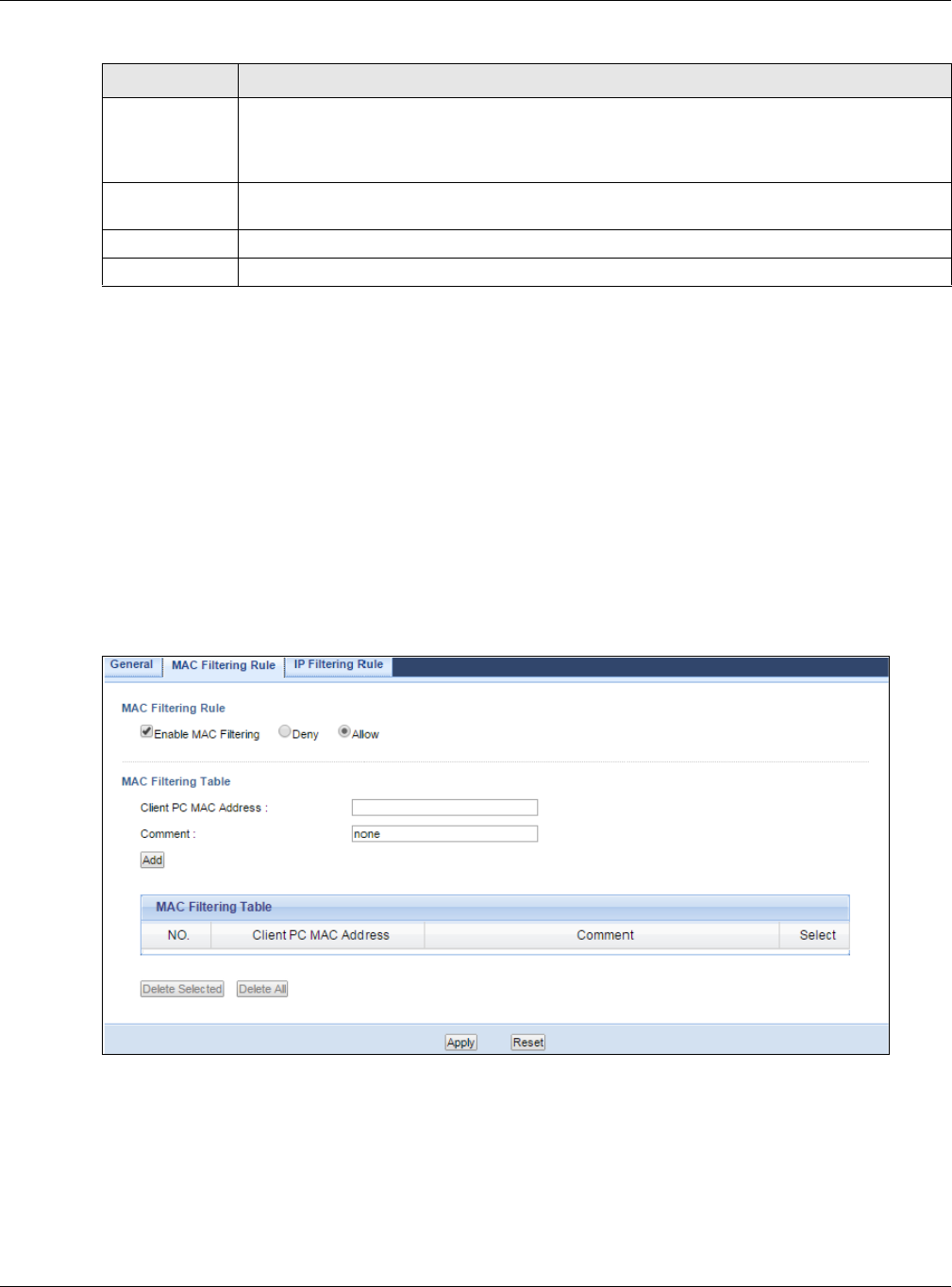
Chapter 19 Firewall
NBG6515 User’s Guide
129
19.5 MAC Filtering Rule Screen
If an outside user attempts to probe an unsupported port on your NBG, an ICMP response packet is
automatically returned. This allows the outside user to know the NBG exists. Use this screen to
prevent the ICMP response packet from being sent. This keeps outsiders from discovering your NBG
when unsupported ports are probed.
You can also use this screen to enable service blocking, enter/delete/modify the services you want
to block and the date/time you want to block them.
Click Security > Firewall > MAC Filtering Rule. The screen appears as shown next.
Figure 98 Security > Firewall > MAC Filtering Rule
ICMP Internet Control Message Protocol is a message control and error-reporting protocol
between a host server and a gateway to the Internet. ICMP uses Internet Protocol (IP)
datagrams, but the messages are processed by the TCP/IP software and directly apparent to
the application user.
Enable ICMP
(WAN Ping)
Select this check box to activate the ICMP. The NBG will respond to WAN incoming Ping
requests.
Apply Click Apply to save the settings.
Reset Click Reset to start configuring this screen again.
Table 63 Security > Firewall > General
LABEL DESCRIPTION

Chapter 19 Firewall
NBG6515 User’s Guide
130
The following table describes the labels in this screen.
See Appendix E on page 232 for commonly used services and port numbers.
19.6 IP Filtering Rule Screen
If an outside user attempts to probe an unsupported port on your NBG, an ICMP response packet is
automatically returned. This allows the outside user to know the NBG exists. Use this screen to
prevent the ICMP response packet from being sent. This keeps outsiders from discovering your NBG
when unsupported ports are probed.
You can also use this screen to enable service blocking, enter/delete/modify the services you want
to block and the date/time you want to block them.
Click Security > Firewall > IP Filtering Rule. The screen appears as shown next.
Table 64 Security > Firewall > MAC Filtering Rule
LABEL DESCRIPTION
MAC Filtering Rule
Enable MAC
Filtering
Select this check box to enable MAC address filtering.
Define the filter action for the list of MAC addresses in the MAC Filtering Table.
Select Allow to permit access to the NBG, MAC addresses not listed will be denied access to
the NBG.
Select Deny to block access to the NBG, MAC addresses not listed will be allowed to access
the NBG.
MAC Filtering Table
Client PC MAC
Address
Enter the MAC address of the computer for which the MAC filtering rule applies.
Comment Enter a name that identifies or describes the firewall rule.
Add Click this to add the MAC filtering rule.
MAC Filtering Table
NO. This is the number of an individual MAC filtering rule.
Client PC MAC
Address
This field displays the MAC address of the computer.
Comment This field displays the descriptions of the MAC filtering rule.
Select Select the MAC filtering rule which you want to delete.
Delete Selected Click the Delete Selected button to remove the MAC filtering rule which selected from the
MAC Filtering Table. A window displays asking you to confirm that you want to delete the
rule.
Delete All Click the Delete All button to remove all MAC filtering rules from the NBG. A window
displays asking you to confirm that you want to delete all rules.
Apply Click Apply to save your changes back to the NBG.
Reset Click Reset to start configuring this screen again.
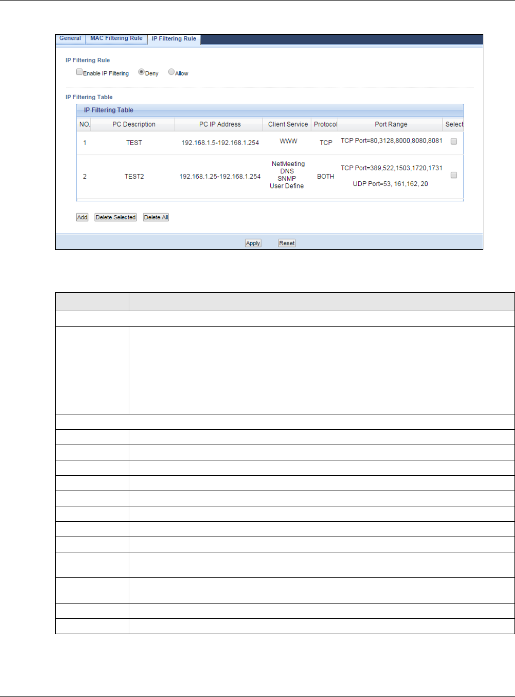
Chapter 19 Firewall
NBG6515 User’s Guide
131
Figure 99 Security > Firewall > IP Filtering Rule
The following table describes the labels in this screen.
Table 65 Security > Firewall > IP Filtering Rule
LABEL DESCRIPTION
IP Filtering Rule
Enable IP
Filtering
Select this check box to enable IP filtering.
Define the filter action for the list of MAC addresses in the IP Filtering Table.
Select Allow to permit access to the NBG, IP addresses not listed will be denied access to
the NBG.
Select Deny to block access to the NBG, IP addresses not listed will be allowed to access
the NBG.
IP Filtering Table
NO. This is the number of an individual IP filtering rule.
PC Description This field displays a description to identify this rule.
PC IP Address This field displays the IP address (or a range of IP addresses) of the computer.
Client Service This field displays the clients services you selected.
Protocol This field displays the protocol used for the service.
Port Range This field displays the port number(s).
Select Select the IP filtering rule which you want to delete.
Add Click this to add the IP filtering rule.
Delete Selected Click the Delete Selected button to remove the IP filtering rule which selected from the IP
Filtering Table. A window displays asking you to confirm that you want to delete the rule.
Delete All Click the Delete All button to remove all IP filtering rules from the NBG. A window displays
asking you to confirm that you want to delete all rules.
Apply Click Apply to save your changes back to the NBG.
Reset Click Reset to start configuring this screen again.
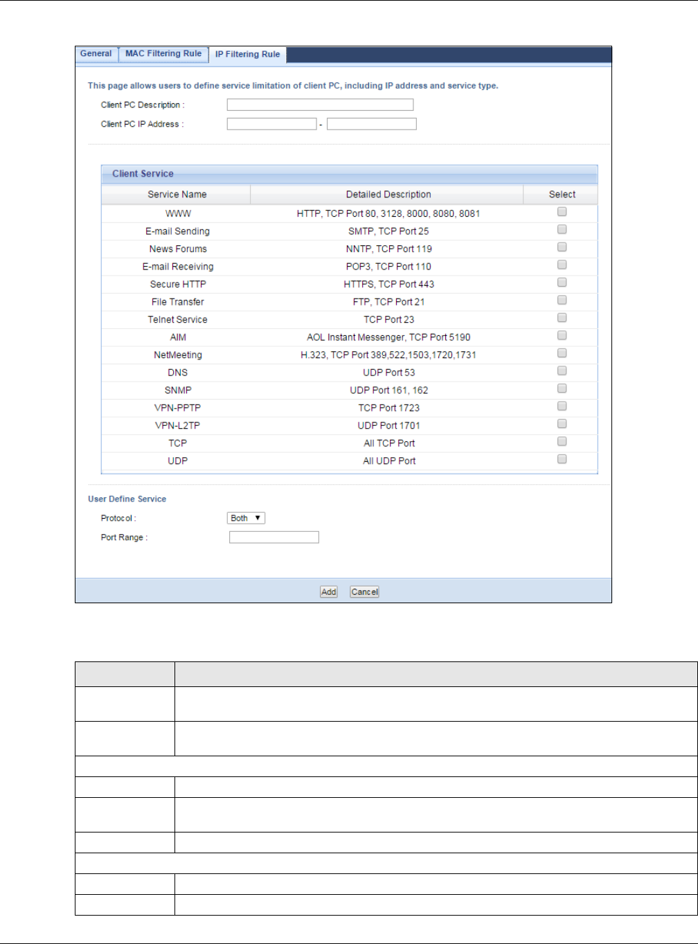
Chapter 19 Firewall
NBG6515 User’s Guide
132
Figure 100 Security > Firewall > IP Filtering Rule: Add
The following table describes the labels in this screen.
Table 66 Security > Firewall > IP Filtering Rule: Add
LABEL DESCRIPTION
Client PC
Description
Enter a name that identifies or describes the firewall rule.
Client PC IP
Address
Enter the IP address of the computer for which the IP filtering rule applies.
Client Service
Service Name This field displays the services which be provided from clients.
Detailed
Description
This field displays the details of Service Name.
Select Select client services which you want to apply.
User Define Service
Protocol Select the transport layer protocol used for the service. Choices are TCP, UDP, or Both.
Port Range Type a range of port numbers.

Chapter 19 Firewall
NBG6515 User’s Guide
133
See Appendix E on page 232 for commonly used services and port numbers.
Add Click Apply to save your changes back to the NBG.
Cancel Click Cancel to exit this screen without saving.
Table 66 Security > Firewall > IP Filtering Rule: Add
LABEL DESCRIPTION

NBG6515 User’s Guide
134
CHAPTER 20
Content Filter
20.1 Overview
This chapter provides a brief overview of content filtering using the embedded web GUI.
Internet content filtering allows you to create and enforce Internet access policies tailored to your
needs. Content filtering is the ability to block certain web features or specific URL keywords.
20.2 What You Can Do
Use the Content Filter (Section 20.4 on page 135) screen to restrict web features, add
keywords for blocking and designate a trusted computer.
20.3 What You Need To Know
Content filtering allows you to block certain web features, such as cookies, and/or block access to
specific web sites. For example, you can configure one policy that blocks John Doe’s access to arts
and entertainment web pages.
20.3.1 Content Filtering Profiles
A content filtering profile conveniently stores your custom settings for the following features.
Restrict Web Features
The NBG can disable web proxies and block web features such as ActiveX controls, Java applets and
cookies.
Keyword Blocking URL Checking
The NBG checks the URL’s domain name (or IP address) and file path separately when performing
keyword blocking.
The URL’s domain name or IP address is the characters that come before the first slash in the URL.
For example, with the URL www.zyxel.com.tw/news/pressroom.php, the domain name is
www.zyxel.com.tw.
The file path is the characters that come after the first slash in the URL. For example, with the URL
www.zyxel.com.tw/news/pressroom.php, the file path is news/pressroom.php.
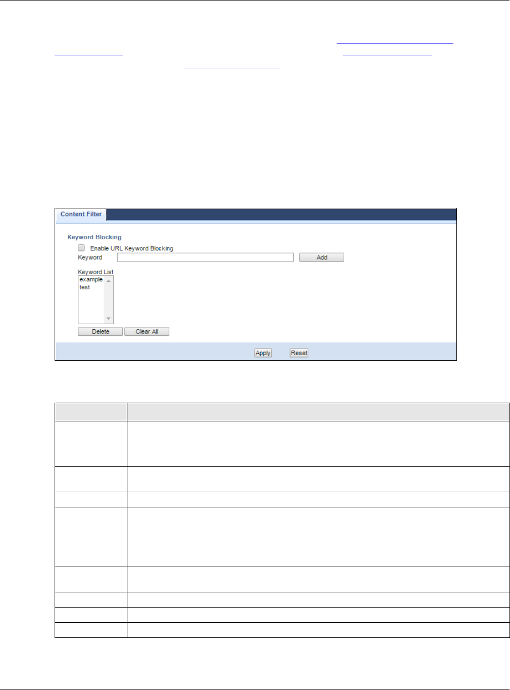
Chapter 20 Content Filter
NBG6515 User’s Guide
135
Since the NBG checks the URL’s domain name (or IP address) and file path separately, it will not
find items that go across the two. For example, with the URL www.zyxel.com.tw/news/
pressroom.php, the NBG would find “tw” in the domain name (www.zyxel.com.tw). It would also
find “news” in the file path (news/pressroom.php) but it would not find “tw/news”.
20.4 Content Filter Screen
Use this screen to restrict web features, add keywords for blocking and designate a trusted
computer.
Click Security > Content Filter to open the Content Filter screen.
Figure 101 Security > Content Filter > Content Filter
The following table describes the labels in this screen.
Table 67 Security > Content Filter > Content Filter
LABEL DESCRIPTION
Enable URL
Keyword
Blocking
The NBG can block Web sites with URLs that contain certain keywords in the domain name
or IP address. For example, if the keyword "bad" was enabled, all sites containing this
keyword in the domain name or IP address will be blocked, e.g., URL http://
www.website.com/bad.html would be blocked. Select this check box to enable this feature.
Keyword Type a keyword in this field. You may use any character (up to 64 characters). Wildcards are
not allowed. You can also enter a numerical IP address.
Keyword List This list displays the keywords already added.
Add Click Add after you have typed a keyword.
Repeat this procedure to add other keywords. Up to 64 keywords are allowed.
When you try to access a web page containing a keyword, you will get a message telling you
that the content filter is blocking this request.
Delete Highlight a keyword in the lower box and click Delete to remove it. The keyword disappears
from the text box after you click Apply.
Clear All Click this button to remove all of the listed keywords.
Apply Click Apply to save your changes.
Reset Click Reset to begin configuring this screen afresh
NBG6515 User’s Guide
136
CHAPTER 21
Bandwidth Management
21.1 Overview
This chapter contains information about configuring bandwidth management and editing rules.
ZyXEL’s Bandwidth Management allows you to specify bandwidth management rules based on an
application.
In the figure below, uplink traffic goes from the LAN device (A) to the WAN device (B). Bandwidth
management is applied before sending the packets out to the WAN. Downlink traffic comes back
from the WAN device (B) to the LAN device (A). Bandwidth management is applied before sending
the traffic out to LAN.
Figure 102 Bandwidth Management Example
You can allocate specific amounts of bandwidth capacity (bandwidth budgets) to individual
applications (like VoIP, Web, FTP, and E-mail for example).
21.2 What You Can Do
•Use the General screen (Section 21.4 on page 137) to enable bandwidth management and
assign bandwidth values.
•Use the Advanced screen (Section 21.5 on page 137) to configure bandwidth managements rule
for the pre-defined services and applications.
AB
-> VOIP
-> FTP
-> HTTP
-> Chat, Email
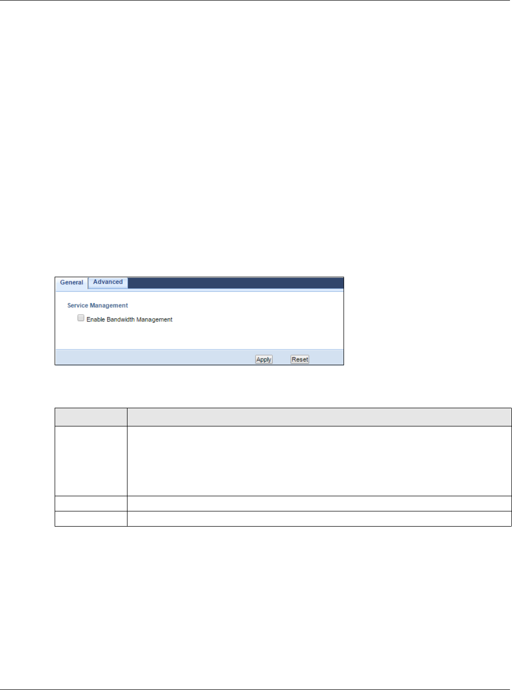
Chapter 21 Bandwidth Management
NBG6515 User’s Guide
137
21.3 What You Need To Know
The sum of the bandwidth allotments that apply to the WAN interface (LAN to WAN, WLAN to WAN)
must be less than or equal to the Upstream Bandwidth that you configure in the Bandwidth
Management Advanced screen (Section 21.5 on page 137).
The sum of the bandwidth allotments that apply to the LAN interface (WAN to LAN, WAN to WLAN)
must be less than or equal to the Downstream Bandwidth that you configure in the Bandwidth
Management Advanced screen Section 21.5 on page 137.
21.4 General Screen
Use this screen to have the NBG apply bandwidth management.
Click Management > Bandwidth Management to open the bandwidth management General
screen.
Figure 103 Management > Bandwidth Management > General
The following table describes the labels in this screen.
21.5 Advanced Screen
Use this screen to configure bandwidth management rules for the pre-defined services or
applications.
You can also use this screen to configure bandwidth management rule for other services or
applications that are not on the pre-defined list of NBG. Additionally, you can define the source and
destination IP addresses and port for a service or application.
Table 68 Management > Bandwidth Management > General
LABEL DESCRIPTION
Enable
Bandwidth
Management
This field allows you to have NBG apply bandwidth management.
Enable bandwidth management to give traffic that matches a bandwidth rule priority over
traffic that does not match a bandwidth rule.
Enabling bandwidth management also allows you to control the maximum or minimum
amounts of bandwidth that can be used by traffic that matches a bandwidth rule.
Apply Click Apply to save your customized settings.
Reset Click Reset to begin configuring this screen afresh.
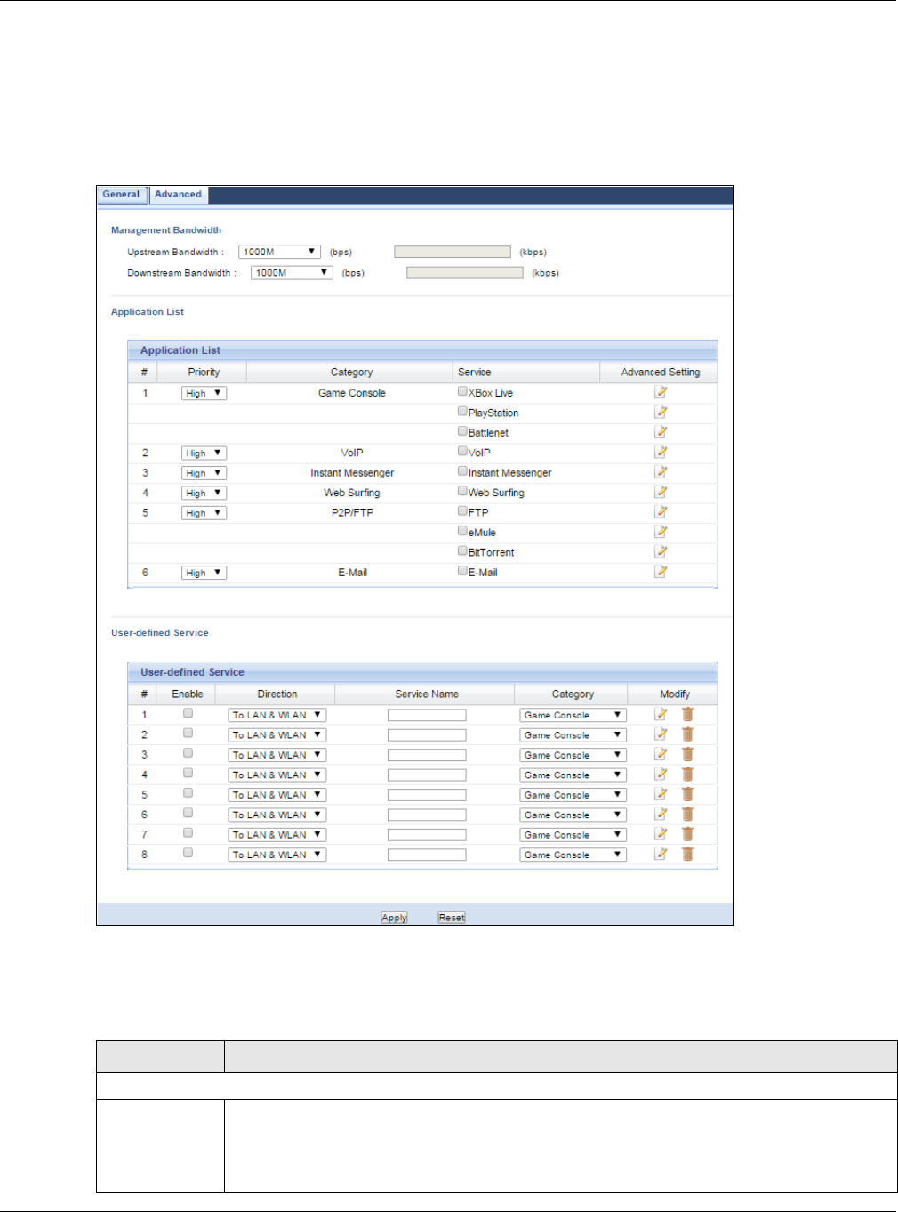
Chapter 21 Bandwidth Management
NBG6515 User’s Guide
138
Note: The two tables shown in this screen can be configured and applied at the same
time.
Click Management > Bandwidth Management > Advanced to open the bandwidth
management Advanced screen.
Figure 104 Management > Bandwidth Management > Advanced
The following table describes the labels in this screen.
Table 69 Management > Bandwidth Management > Advanced
LABEL DESCRIPTION
Management Bandwidth
Upstream
Bandwidth
Select the total amount of bandwidth (from 64 Kilobits to 50 Megabits) that you want to
dedicate to uplink traffic. If you select User Defined, type the total amount of bandwidth
that you want to dedicate to uplink (or outgoing) traffic in the (kbps) text box.
This is traffic from LAN/WLAN to WAN.

Chapter 21 Bandwidth Management
NBG6515 User’s Guide
139
21.5.1 Rule Configuration: Application Rule Configuration
If you want to edit a bandwidth management rule for a pre-defined service or application, click the
Edit icon in the Application List table of the Advanced screen. The following screen displays.
Downstream
Bandwidth
Select the total amount of bandwidth (from 64 Kilobits to 50 Megabits) that you want to
dedicate to uplink traffic. If you select User Defined, type the total amount of bandwidth
that you want to dedicate to downlink (or incoming) traffic in the (kbps) text box.
This is traffic from WAN to LAN/WLAN.
Application List Use this table to allocate specific amounts of bandwidth based on a pre-defined service.
#This is the number of an individual bandwidth management rule.
Priority Select a priority from the drop down list box. Choose High, Mid or Low.
•High - Select this for voice traffic or video that is especially sensitive to jitter (jitter is
the variations in delay).
•Mid - Select this for "excellent effort" or better than best effort and would include
important business traffic that can tolerate some delay.
•Low - Select this for non-critical "background" traffic such as bulk transfers that are
allowed but that should not affect other applications and users.
Category This is the category where a service belongs.
Service This is the name of the service.
Select the check box to have the NBG apply this bandwidth management rule.
Advanced
Setting
Click the Edit icon to open the Rule Configuration screen where you can modify the rule.
User-defined
Service
Use this table to allocate specific amounts of bandwidth to specific applications or services
you specify.
#This is the number of an individual bandwidth management rule.
Enable Select this check box to have the NBG apply this bandwidth management rule.
Direction Select TO LAN/WLAN to apply bandwidth management to traffic from WAN to LAN/WLAN.
Select TO WAN to apply bandwidth management to traffic from LAN/WLAN to WAN.
Service Name Enter a descriptive name for the bandwidth management rule.
Category This is the category where a service belongs.
Modify Click the Edit icon to open the Rule Configuration screen. Modify an existing rule or
create a new rule in the Rule Configuration screen. See Section 21.5.2 on page 140 for
more information.
Click the Remove icon to delete a rule.
Apply Click Apply to save your customized settings.
Reset Click Reset to begin configuring this screen afresh.
Table 69 Management > Bandwidth Management > Advanced (continued)
LABEL DESCRIPTION

Chapter 21 Bandwidth Management
NBG6515 User’s Guide
140
Figure 105 Bandwidth Management Rule Configuration: Application List
The following table describes the labels in this screen.
21.5.2 Rule Configuration: User Defined Service Rule Configuration
If you want to edit a bandwidth management rule for other applications or services, click the Edit
icon in the User-defined Service table of the Advanced screen. The following screen displays.
Figure 106 Bandwidth Management Rule Configuration: User-defined Service
Table 70 Bandwidth Management Rule Configuration: Application List
LABEL DESCRIPTION
#This is the number of an individual bandwidth management rule.
Enable Select an interface’s check box to enable bandwidth management on that interface.
Direction These read-only labels represent the physical interfaces. Bandwidth management applies to
all traffic flowing out of the router through the interface, regardless of the traffic’s source.
Traffic redirect or IP alias may cause LAN-to-LAN traffic to pass through the NBG and be
managed by bandwidth management.
Bandwidth Select Maximum Bandwidth or Minimum Bandwidth and specify the maximum or
minimum bandwidth allowed for the rule in kilobits per second.
Protocol This is the protocol (TCP, UDP or user-defined) used for the service.
OK Click OK to save your customized settings.
Cancel Click Cancel to exit this screen without saving.

Chapter 21 Bandwidth Management
NBG6515 User’s Guide
141
The following table describes the labels in this screen
Table 71 Bandwidth Management Rule Configuration: User-defined Service
See Appendix E on page 232 for commonly used services and port numbers.
LABEL DESCRIPTION
BW Budget Select Maximum Bandwidth or Minimum Bandwidth and specify the maximum or
minimum bandwidth allowed for the rule in kilobits per second.
Destination
Address Range
Enter the IP address range of the destination computer.
The NBG applies bandwidth management to the service or application that is entering this
computer.
Destination
Port Range
This is the port number of the destination that define the traffic type, for example TCP port
80 defines web traffic.
Source Address
Range
Enter the IP address range of the computer that initializes traffic for the application or
service.
The NBG applies bandwidth management to traffic initiating from this computer.
Source Port
Range
This is the port number of the source that define the traffic type, for example TCP port 80
defines web traffic.
Protocol Select the protocol (TCP, UDP) for which the bandwidth management rule applies.
Apply Click Apply to save your customized settings.
Cancel Click Cancel to exit this screen without saving.

NBG6515 User’s Guide
142
CHAPTER 22
Remote Management
22.1 Overview
This chapter provides information on the Remote Management screens.
Remote Management allows you to manage your NBG from a remote location through the following
interfaces:
•LAN and WAN
•LAN only
•WAN only
Note: The NBG is managed using the Web Configurator.
22.2 What You Can Do
Use the WWW screen (Section 22.4 on page 143) to define the interface/s from which the NBG can
be managed remotely and specify a secure client that can manage the NBG.
22.3 What You Need to Know
Remote management over LAN or WAN will not work when:
1The IP address in the Secured Client IP Address field (Section 22.4 on page 143) does not
match the client IP address. If it does not match, the NBG will disconnect the session immediately.
2There is already another remote management session. You may only have one remote
management session running at one time.
3There is a firewall rule that blocks it.
22.3.1 Remote Management and NAT
When NAT is enabled:
• Use the NBG’s WAN IP address when configuring from the WAN.
• Use the NBG’s LAN IP address when configuring from the LAN.
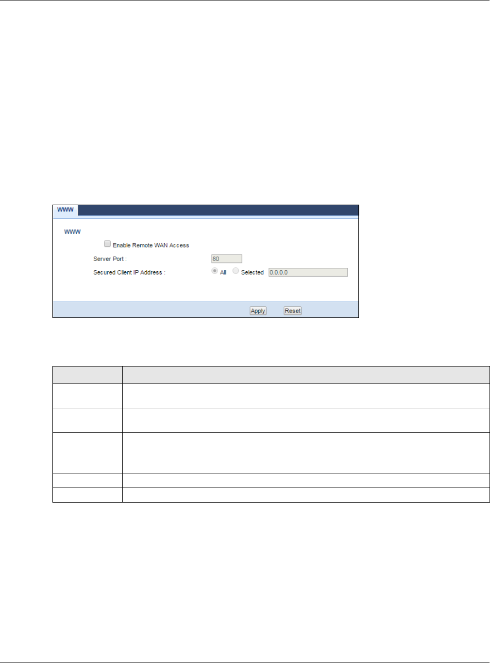
Chapter 22 Remote Management
NBG6515 User’s Guide
143
22.3.2 System Timeout
There is a default system management idle timeout of five minutes (three hundred seconds). The
NBG automatically logs you out if the management session remains idle for longer than this timeout
period. The management session does not time out when a statistics screen is polling. You can
change the timeout period in the System screen
22.4 WWW Screen
To change your NBG’s remote management settings, click Management > Remote Management
> WWW.
Figure 107 Management > Remote Management > WWW
The following table describes the labels in this screen
Table 72 Management > Remote Management > WWW
LABEL DESCRIPTION
Enable Remote
WAN Access
Select this check box to enable Remote WAN Access.
Server Port You may change the server port number for a service if needed, however you must use the
same port number in order to use that service for remote management.
Secured Client
IP Address
Select All to allow all computes to access the NBG.
Otherwise, check Selected and specify the IP address of the computer that can access the
NBG.
Apply Click Apply to save your customized settings and exit this screen.
Reset Click Reset to begin configuring this screen afresh.

NBG6515 User’s Guide
144
CHAPTER 23
Universal Plug-and-Play (UPnP)
23.1 Overview
This chapter introduces the UPnP feature in the web configurator.
Universal Plug and Play (UPnP) is a distributed, open networking standard that uses TCP/IP for
simple peer-to-peer network connectivity between devices. A UPnP device can dynamically join a
network, obtain an IP address, convey its capabilities and learn about other devices on the network.
In turn, a device can leave a network smoothly and automatically when it is no longer in use.
23.2 What You Can Do
Use the UPnP screen (Section 23.4 on page 145) to enable UPnP on your NBG.
23.3 What You Need to Know
UPnP hardware is identified as an icon in the Network Connections folder (Windows XP). Each UPnP
compatible device installed on your network will appear as a separate icon. Selecting the icon of a
UPnP device will allow you to access the information and properties of that device.
23.3.1 NAT Traversal
UPnP NAT traversal automates the process of allowing an application to operate through NAT. UPnP
network devices can automatically configure network addressing, announce their presence in the
network to other UPnP devices and enable exchange of simple product and service descriptions.
NAT traversal allows the following:
• Dynamic port mapping
• Learning public IP addresses
• Assigning lease times to mappings
Windows Messenger is an example of an application that supports NAT traversal and UPnP.
See the NAT chapter for more information on NAT.
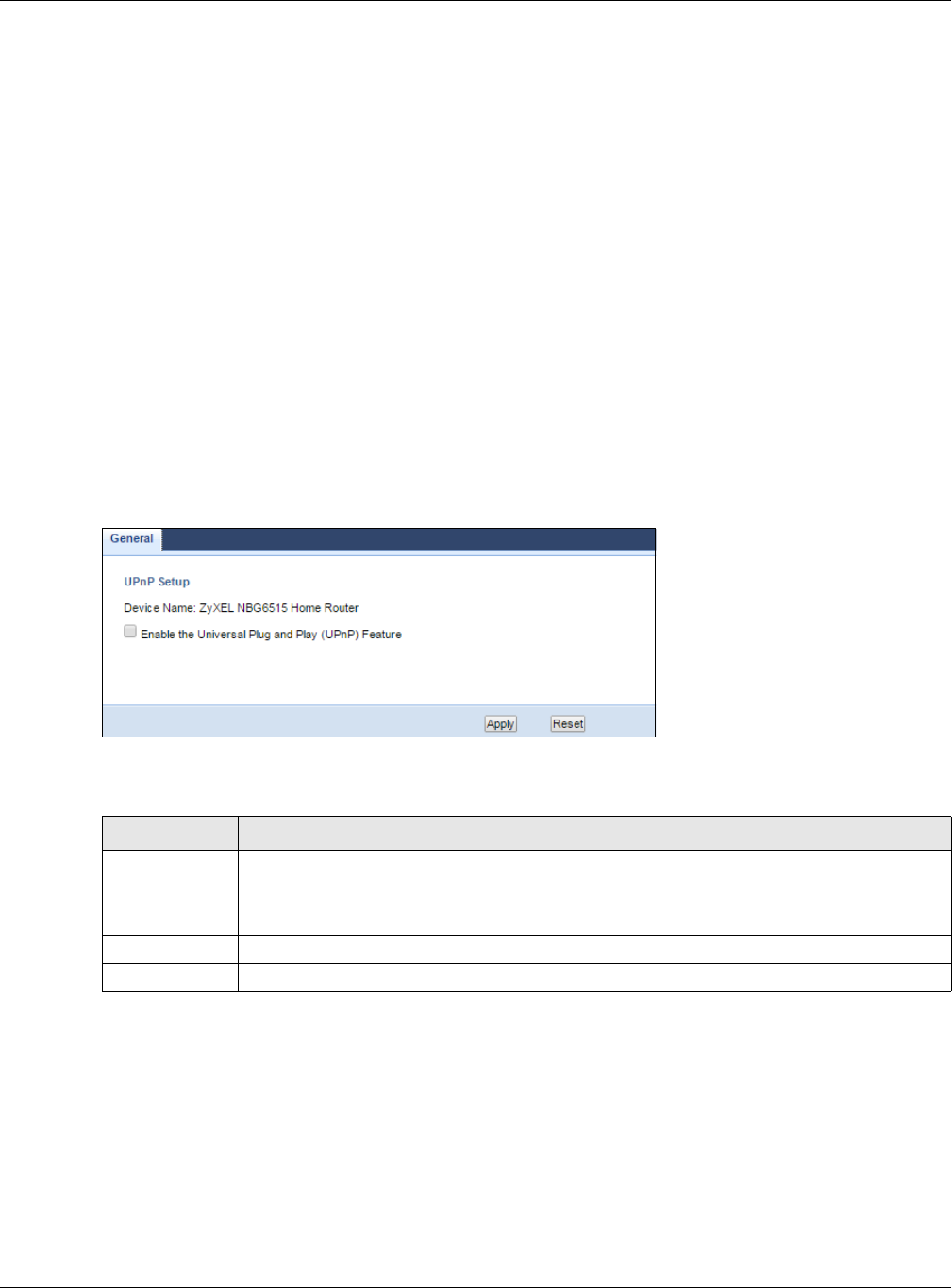
Chapter 23 Universal Plug-and-Play (UPnP)
NBG6515 User’s Guide
145
23.3.2 Cautions with UPnP
The automated nature of NAT traversal applications in establishing their own services and opening
firewall ports may present network security issues. Network information and configuration may also
be obtained and modified by users in some network environments.
When a UPnP device joins a network, it announces its presence with a multicast message. For
security reasons, the NBG allows multicast messages on the LAN only.
All UPnP-enabled devices may communicate freely with each other without additional configuration.
Disable UPnP if this is not your intention.
23.4 UPnP Screen
Use this screen to enable UPnP on your NBG.
Click Management > UPnP to display the screen shown next.
Figure 108 Management > UPnP
The following table describes the fields in this screen.
23.5 Technical Refereance
The sections show examples of using UPnP.
Table 73 Management > UPnP
LABEL DESCRIPTION
Enable the
Universal Plug
and Play
(UPnP) Feature
Select this check box to activate UPnP. Be aware that anyone could use a UPnP application
to open the web configurator's login screen without entering the NBG's IP address (although
you must still enter the password to access the web configurator).
Apply Click Apply to save the setting to the NBG.
Reset Click Reset to return to the previously saved settings.
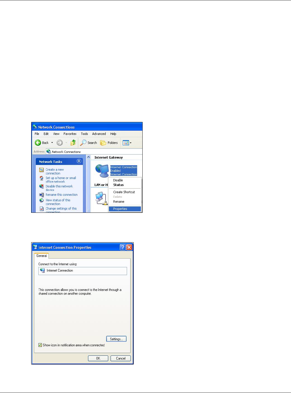
Chapter 23 Universal Plug-and-Play (UPnP)
NBG6515 User’s Guide
146
23.5.1 Using UPnP in Windows XP Example
This section shows you how to use the UPnP feature in Windows XP. You must already have UPnP
installed in Windows XP and UPnP activated on the NBG.
Make sure the computer is connected to a LAN port of the NBG. Turn on your computer and the
NBG.
23.5.1.1 Auto-discover Your UPnP-enabled Network Device
1Click start and Control Panel. Double-click Network Connections. An icon displays under
Internet Gateway.
2Right-click the icon and select Properties.
Figure 109 Network Connections
3In the Internet Connection Properties window, click Settings to see the port mappings there
were automatically created.
Figure 110 Internet Connection Properties
4You may edit or delete the port mappings or click Add to manually add port mappings.
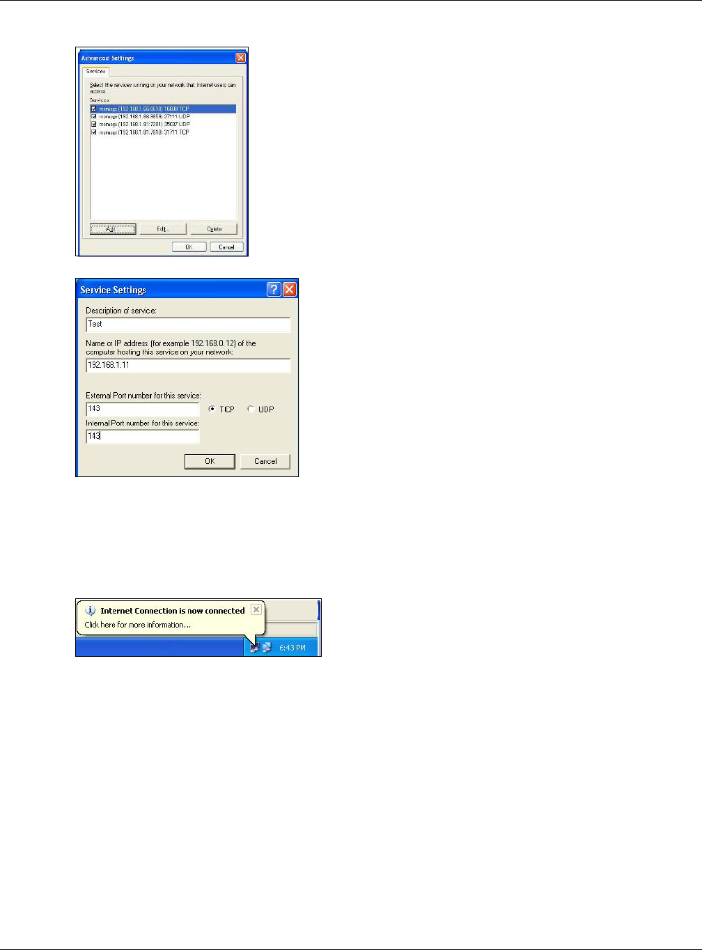
Chapter 23 Universal Plug-and-Play (UPnP)
NBG6515 User’s Guide
147
Figure 111 Internet Connection Properties: Advanced Settings
Figure 112 Internet Connection Properties: Advanced Settings: Add
Note: When the UPnP-enabled device is disconnected from your computer, all port
mappings will be deleted automatically.
5Select Show icon in notification area when connected option and click OK. An icon displays in
the system tray.
Figure 113 System Tray Icon
6Double-click on the icon to display your current Internet connection status.
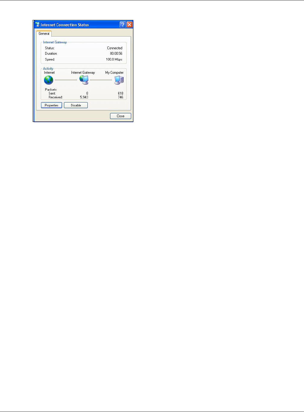
Chapter 23 Universal Plug-and-Play (UPnP)
NBG6515 User’s Guide
148
Figure 114 Internet Connection Status
23.5.2 Web Configurator Easy Access
With UPnP, you can access the web-based configurator on the NBG without finding out the IP
address of the NBG first. This comes helpful if you do not know the IP address of the NBG.
Follow the steps below to access the web configurator.
1Click Start and then Control Panel.
2Double-click Network Connections.
3Select My Network Places under Other Places.
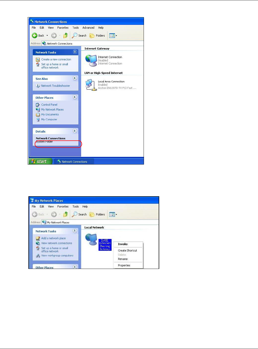
Chapter 23 Universal Plug-and-Play (UPnP)
NBG6515 User’s Guide
149
Figure 115 Network Connections
4An icon with the description for each UPnP-enabled device displays under Local Network.
5Right-click on the icon for your NBG and select Invoke. The web configurator login screen displays.
Figure 116 Network Connections: My Network Places
6Right-click on the icon for your NBG and select Properties. A properties window displays with basic
information about the NBG.
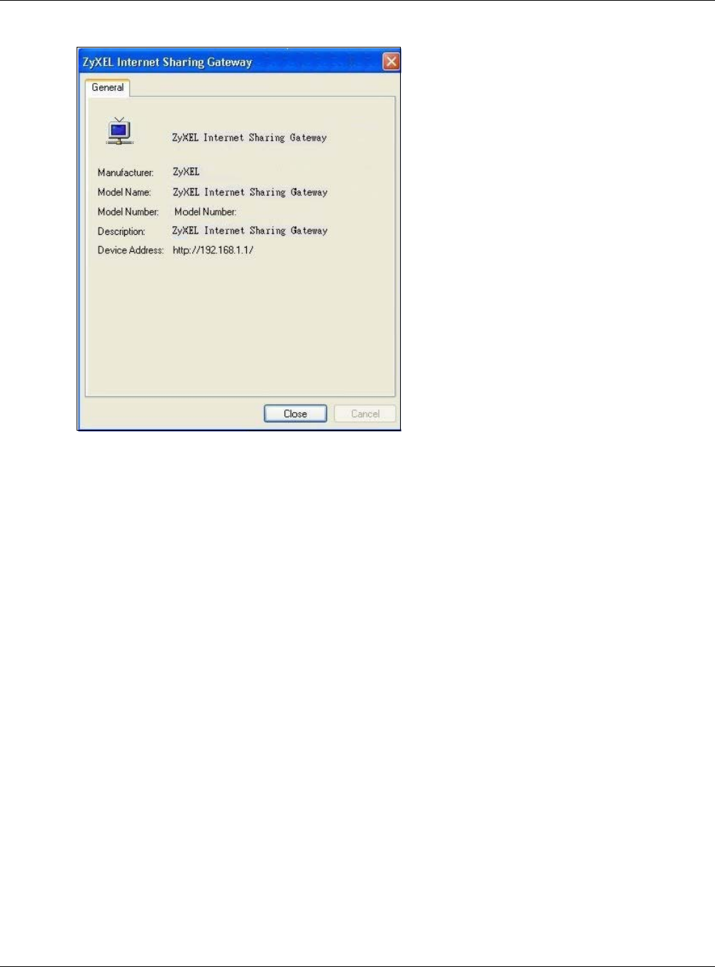
Chapter 23 Universal Plug-and-Play (UPnP)
NBG6515 User’s Guide
150
Figure 117 Network Connections: My Network Places: Properties: Example
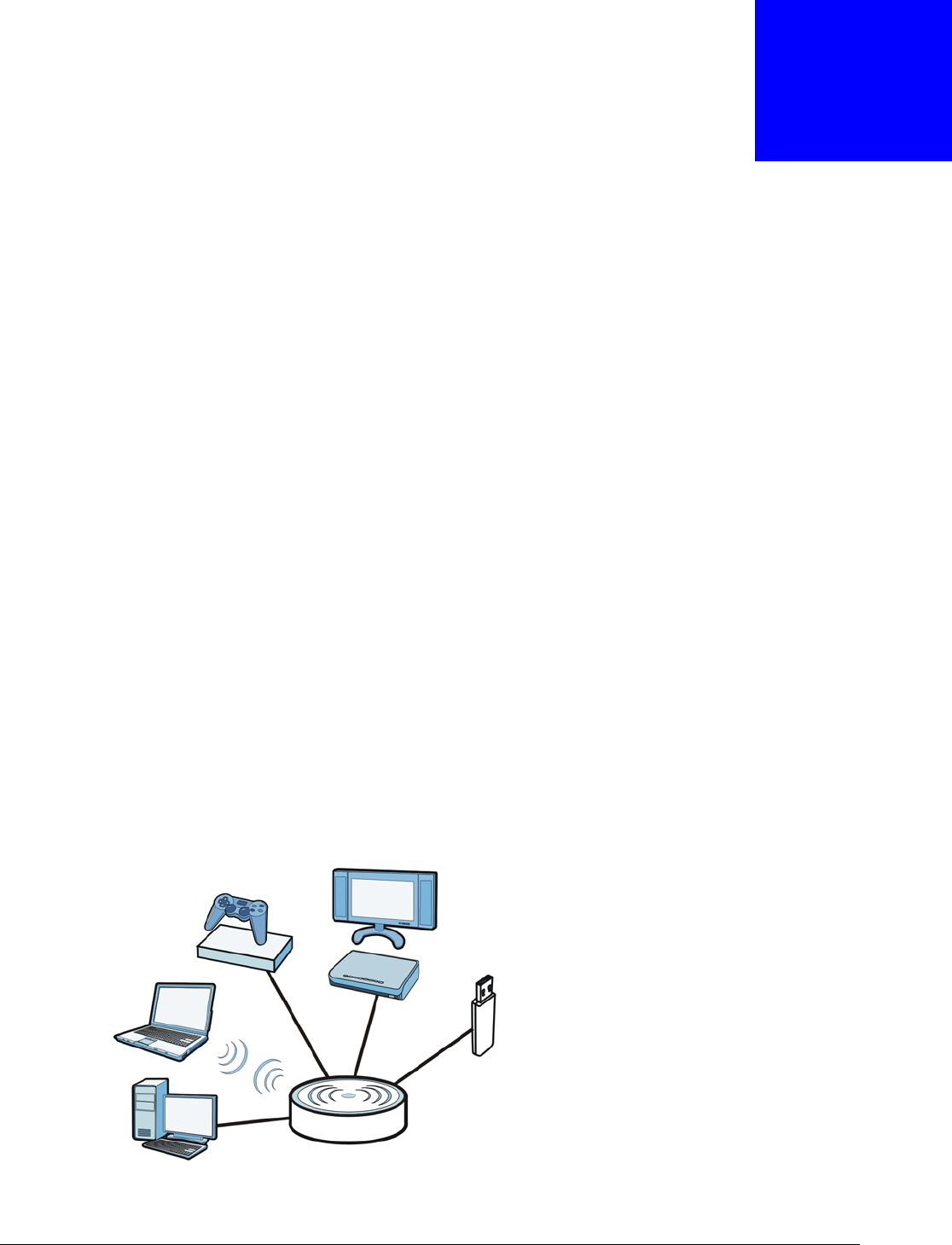
NBG6515 User’s Guide
151
CHAPTER 24
USB Media Sharing
24.1 Overview
This chapter describes how to configure the media sharing settings on the NBG.
Note: The read and write performance may be affected by amount of file-sharing traffic
on your network, type of connected USB device and your USB version (1.1 or 2.0).
Media Server
You can set up your NBG to act as a media server to provide media (like video) to DLNA-compliant
players, such as Windows Media Player, ZyXEL DMAs (Digital Media Adapters), Xboxes or PS3s. The
media server and clients must have IP addresses in the same subnet.
The NBG media server enables you to:
• Publish all folders for everyone to play media files in the USB storage device connected to the
NBG.
• Use hardware-based media clients like the DMA-2500 to play the files.
Note: Anyone on your network can play the media files in the published folders. No user
name and password nor other form of security is required.
The following figure is an overview of the NBG’s media server feature. DLNA devices A and B can
access and play files on a USB device (C) which is connected to the NBG (D).
Figure 118 Media Server Overview
AB
C
D
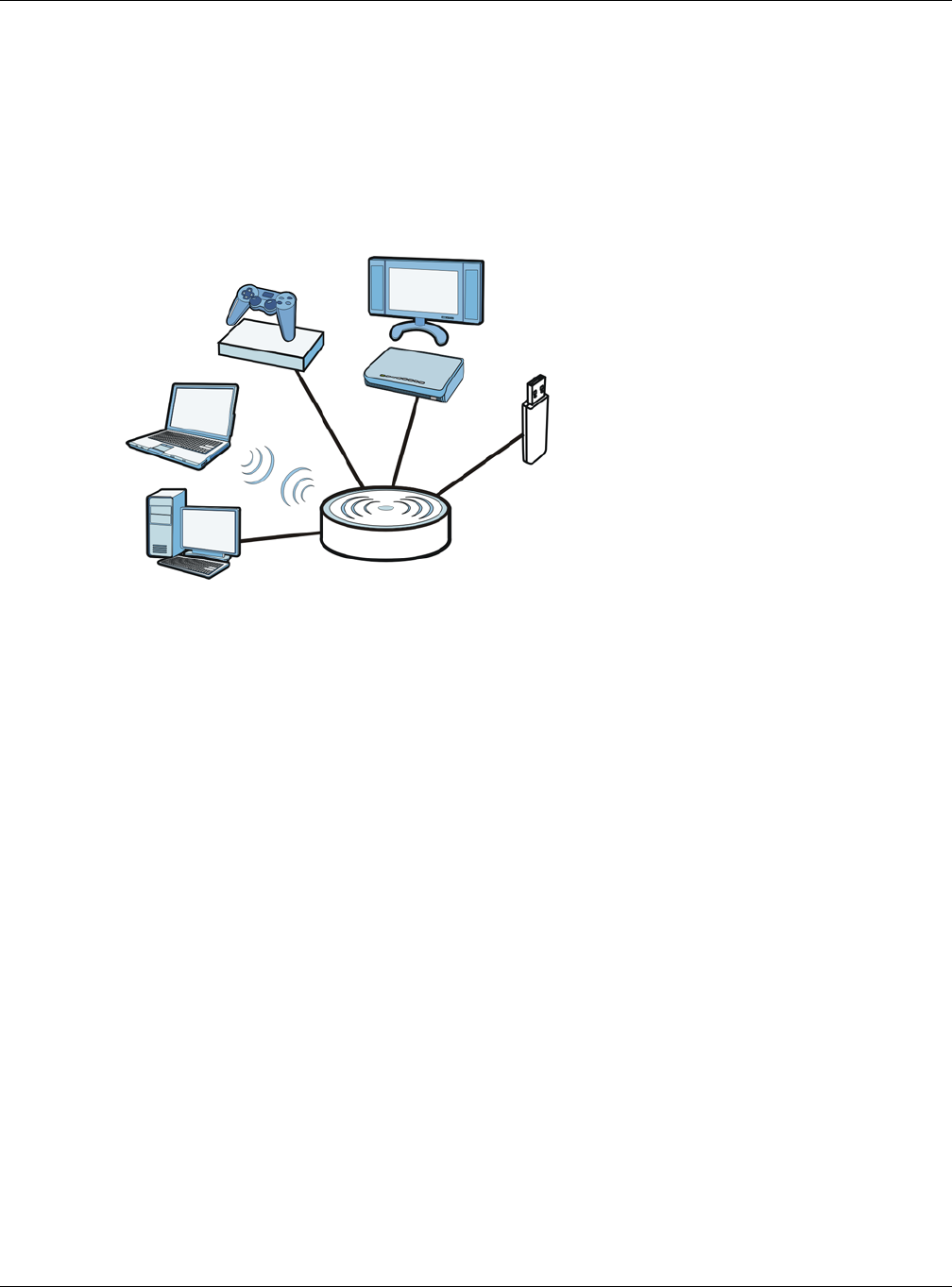
Chapter 24 USB Media Sharing
NBG6515 User’s Guide
152
File-Sharing Server
You can also share files on a USB memory stick or hard drive connected to your NBG with users on
your network.
The following figure is an overview of the NBG’s file-sharing server feature. Computers A and B can
access files on a USB device (C) which is connected to the NBG (D).
Figure 119 File Sharing Overview
24.2 What You Can Do
•Use the SMB/CIFS screen to enable file-sharing via the NBG using Windows Explorer or the
workgroup name. This screen also allow you to configure the workgroup name and create user
accounts (Section 24.5 on page 154).
•Use the DLNA screen to use the NBG as a media server and allow DLNA-compliant devices to
play media files stored in the attached USB device (Section 24.6 on page 155).
•Use the FTP screen to allow file sharing via the NBG using FTP and create user accounts (Section
24.7 on page 155).
24.3 What You Need To Know
DLNA
The Digital Living Network Alliance (DLNA) is a group of personal computer and electronics
companies that works to make products compatible in a home network. DLNA clients play files
stored on DLNA servers. The NBG can function as a DLNA-compliant media server and stream files
to DLNA-compliant media clients without any configuration.
A
BC
D

Chapter 24 USB Media Sharing
NBG6515 User’s Guide
153
Workgroup name
This is the name given to a set of computers that are connected on a network and share resources
such as a printer or files. Windows automatically assigns the workgroup name when you set up a
network.
File Systems
A file system is a way of storing and organizing files on your hard drive and storage device. Often
different operating systems such as Windows or Linux have different file systems. The file-sharing
feature on your NBG supports New Technology File System (NTFS), File Allocation Table (FAT) and
FAT32 file systems.
Windows/CIFS
Common Internet File System (CIFS) is a standard protocol supported by most operating systems
in order to share files across the network.
CIFS runs over TCP/IP but uses the SMB (Server Message Block) protocol found in Microsoft
Windows for file and printer access; therefore, CIFS will allow all applications, not just Web
browsers, to open and share files across the Internet.
The NBG uses Common Internet File System (CIFS) protocol for its file sharing functions. CIFS
compatible computers can access the USB file storage devices connected to the NBG. CIFS protocol
is supported on Microsoft Windows, Linux Samba and other operating systems (refer to your
systems specifications for CIFS compatibility).
Samba
SMB is a client-server protocol used by Microsoft Windows systems for sharing files, printers, and
so on.
Samba is a free SMB server that runs on most Unix and Unix-like systems. It provides an
implementation of an SMB client and server for use with non-Microsoft operating systems.
File Transfer Protocol
This is a method of transferring data from one computer to another over a network such as the
Internet.
24.4 Before You Begin
Make sure the NBG is connected to your network and turned on.
1Connect the USB device to one of the NBG’s USB ports.
2The NBG detects the USB device and makes its contents available for browsing. If you are
connecting a USB hard drive that comes with an external power supply, make sure it is connected
to an appropriate power source that is on.
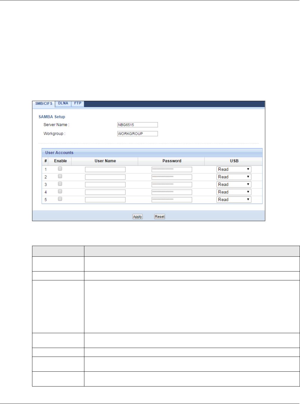
Chapter 24 USB Media Sharing
NBG6515 User’s Guide
154
Note: If your USB device cannot be detected by the NBG, see the troubleshooting for
suggestions.
24.5 SMB/CIFS Screen
Use this screen to set up file-sharing via the NBG using Windows Explorer or the workgroup name.
You can also configure the workgroup name and create file-sharing user accounts. Click
Management > USB > SMB/CIFS.
Figure 120 Management > USB > SMB/CIFS
The following table describes the labels in this screen.
Table 74 Management > USB > SMB/CIFS
LABEL DESCRIPTION
Enable SAMBA Select this to enable file sharing through the NBG using Windows Explorer or by
browsing to your work group.
Server Name Specify the name to identify the NBG in a work group.
Work Group You can add the NBG to an existing or a new workgroup on your network. Enter the
name of the workgroup which your NBG automatically joins. You can set the NBG’s
workgroup name to be exactly the same as the workgroup name to which your
computer belongs.
Note: The NBG will not be able to join the workgroup if your local area network has
restrictions set up that do not allow devices to join a workgroup. In this case,
contact your network administrator.
User Accounts Before you can share files you need a user account. Configure the following fields to set
up a file-sharing account.
#This is the index number of the user account.
Enable This field displays whether a user account is activated or not. Select the check box to
enable the account. Clear the check box to disable the account.
User Name Enter a user name that will be allowed to access the shared files. You can enter up to 20
characters. Only letters and numbers allowed.
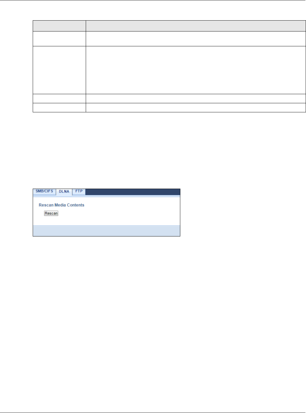
Chapter 24 USB Media Sharing
NBG6515 User’s Guide
155
24.6 DLNA Screen
Use this screen to have the NBG act as a DLNA-compliant media server that lets DLNA-compliant
media clients on your network play video, music, and photos from the NBG (without having to copy
them to another computer). Click Management > USB > DLNA.
Figure 121 Management > USB > DLNA
Click Rescan to have the NBG scan the media files on the connected USB device and do indexing of
the file list again so that DLNA clients can find the new files if any.
24.7 FTP Screen
Use this screen to set up file sharing via the NBG using FTP and create user accounts. Click
Management > USB > FTP.
Password Enter the password used to access the shared files. You can enter up to 20 characters.
Only letters and numbers are allowed. The password is case sensitive.
USB Specify the user’s access rights to the USB storage device which is connected to the
NBG’s USB port.
Read & Write - The user has read and write rights, meaning that the user can create
and edit the files on the connected USB device.
Read - The user has read rights only and can not create or edit the files on the
connected USB device.
Apply Click Apply to save your changes back to the NBG.
Reset Click Reset to return to the previously saved settings.
Table 74 Management > USB > SMB/CIFS (continued)
LABEL DESCRIPTION
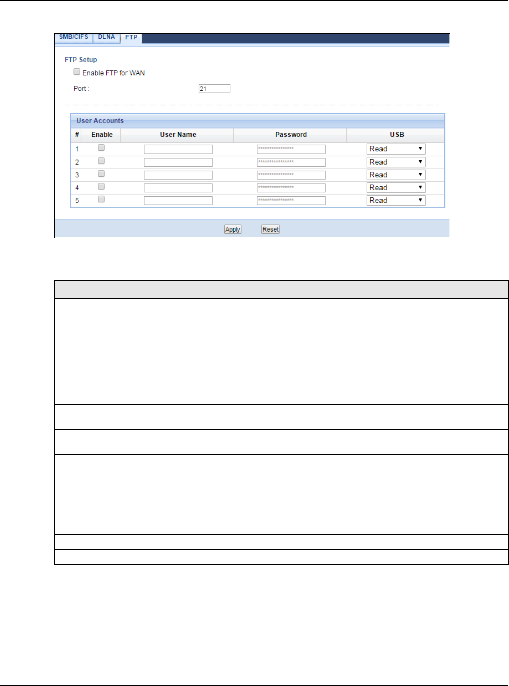
Chapter 24 USB Media Sharing
NBG6515 User’s Guide
156
Figure 122 Management > USB > FTP
The following table describes the labels in this screen.
24.8 Example of Accessing Your Shared Files From a
Computer
You can use Windows Explorer or FTP to access the USB storage devices connected to the NBG.
Table 75 Management > USB > FTP
LABEL DESCRIPTION
Enable FTP for WAN Select this to enable the FTP server on the NBG for file sharing using FTP.
Port You may change the server port number for FTP if needed, however you must use the
same port number in order to use that service for file sharing.
User Accounts Before you can share files you need a user account. Configure the following fields to set
up a file-sharing account.
#This is the index number of the user account.
Enable This field displays whether a user account is activated or not. Select the check box to
enable the account. Clear the check box to disable the account.
User Name Enter a user name that will be allowed to access the shared files. You can enter up to 20
characters. Only letters and numbers allowed.
Password Enter the password used to access the shared files. You can enter up to 20 characters.
Only letters and numbers are allowed. The password is case sensitive.
USB Specify the user’s access rights to the USB storage device which is connected to the
NBG’s USB port.
Read & Write - The user has read and write rights, meaning that the user can create
and edit the files on the connected USB device.
Read - The user has read rights only and can not create or edit the files on the
connected USB device.
Apply Click Apply to save your changes back to the NBG.
Reset Click Reset to return to the previously saved settings.
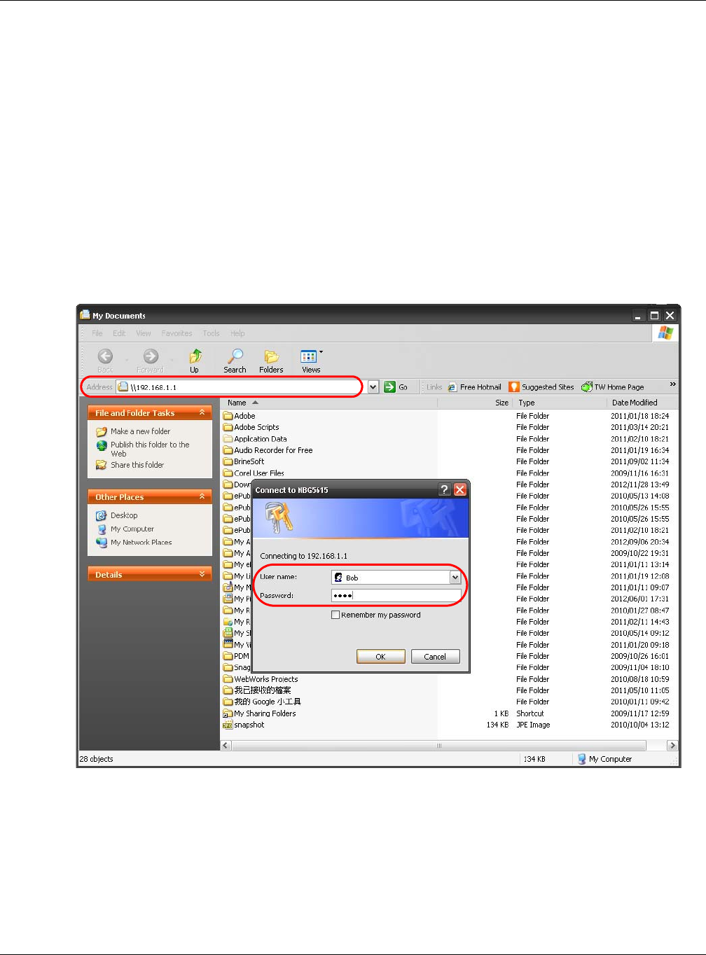
Chapter 24 USB Media Sharing
NBG6515 User’s Guide
157
This example shows you how to use Microsoft’s Windows XP to browse your shared files. Refer to
your operating system’s documentation for how to browse your file structure.
24.8.1 Use Windows Explorer to Share Files
You should have enabled file sharing and created a user account (Bob/1234 for example) with read
and write access to USB in the USB > SMB/CIFS screen.
Open Windows Explorer to access the connected USB device using either Windows Explorer browser
or by browsing to your workgroup.
1In Windows Explorer’s Address bar type a double backslash “\\” followed by the IP address of the
NBG (the default IP address of the NBG in router mode is 192.168.1.1) and press [ENTER]. A
screen asking for password authentication appears. Type the user name and password (Bob and
1234 in this example) and click OK.
Note: Once you log into the shared folder via your NBG, you do not have to relogin unless
you restart your computer.
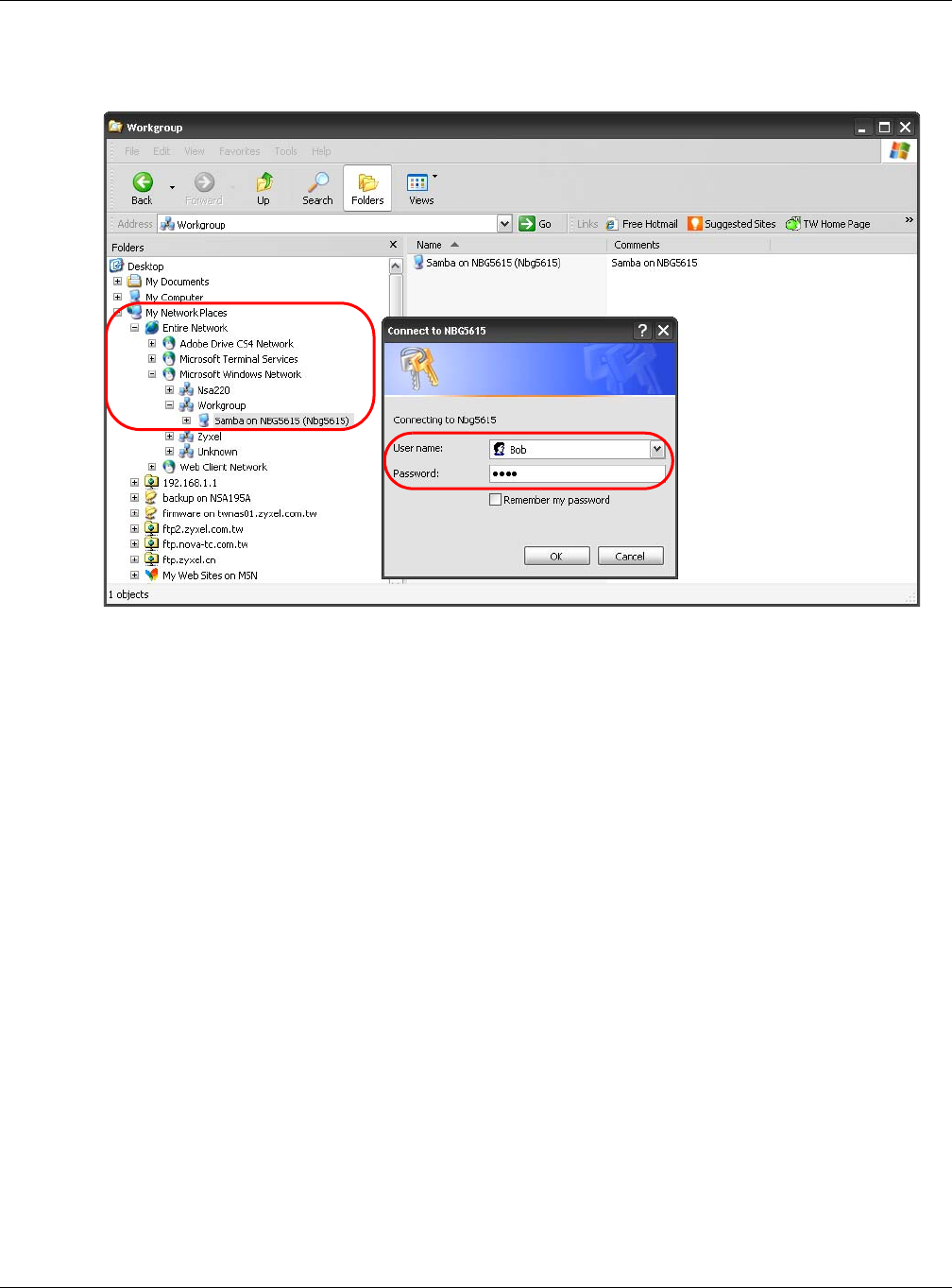
Chapter 24 USB Media Sharing
NBG6515 User’s Guide
158
2You can also use the workgroup name to access files by browsing to the workgroup folder using the
folder tree on the left side of the screen. It is located under My Network Places. In this example
the workgroup name is the default “Workgroup”.
24.8.2 Use FTP to Share Files
You can use FTP to access the USB storage devices connected to the NBG. In this example, we use
the web browser to share files via FTP from the LAN. The way or screen you log into the FTP server
(on the NBG) varies depending on your FTP client. See your FTP client documentation for more
information.
You should have enabled file sharing and created a user account (Bob/1234 for example) with read
and write access to USB in the USB > FTP screen.
1In your web browser’s address or URL bar type “ftp://” followed by the IP address of the NBG (the
default LAN IP address of the NBG in router mode is 192.168.1.1) and click Go or press [ENTER].
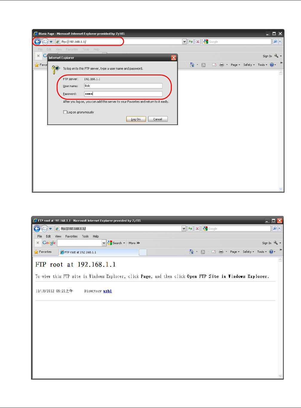
Chapter 24 USB Media Sharing
NBG6515 User’s Guide
159
2A screen asking for password authentication appears. Enter the user name and password (you
configured in the USB > FTP screen) and click Log On.
3The screen changes and shows you the folder for the USB storage device connected to your NBG.
Double-click the folder to display the contents in it.
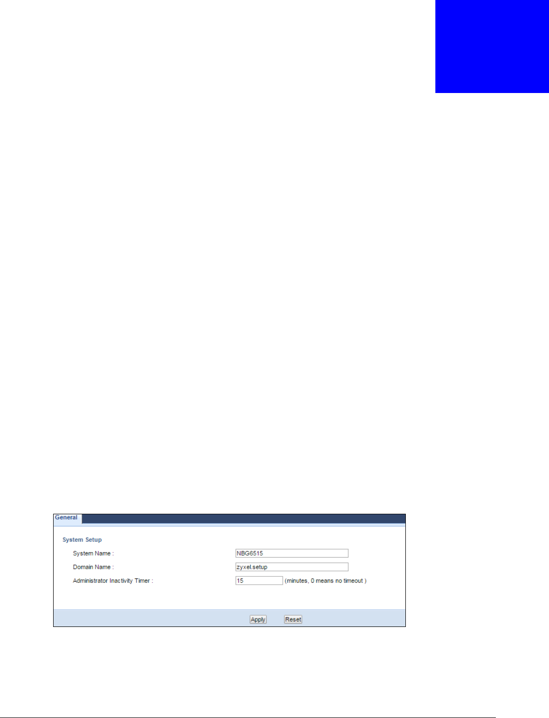
NBG6515 User’s Guide
160
CHAPTER 25
Maintenance
25.1 Overview
This chapter provides information on the Maintenance screens.
25.2 What You Can Do
•Use the General screen to configure system and domain name. You can also set the timeout
period of the management session (Section 25.3 on page 160).
•Use the Password screen to change your NBG’s system password (Section 25.4 on page 161).
•Use the Time screen to change your NBG’s time and date (Section 25.5 on page 162).
•Use the Firmware Upgrade screen to upload firmware to your NBG (Section 25.6 on page 163).
•Use the Backup/Restore screen to view information related to factory defaults, backup
configuration, and restoring configuration (Section 25.8 on page 166).
•Use the Restart screen to reboot the NBG without turning the power off (Section 25.8 on page
166).
25.3 General Screen
Use this screen to set the configure system and domain name as well as management session
timeout period. Click Maintenance > General. The following screen displays.
Figure 123 Maintenance > General
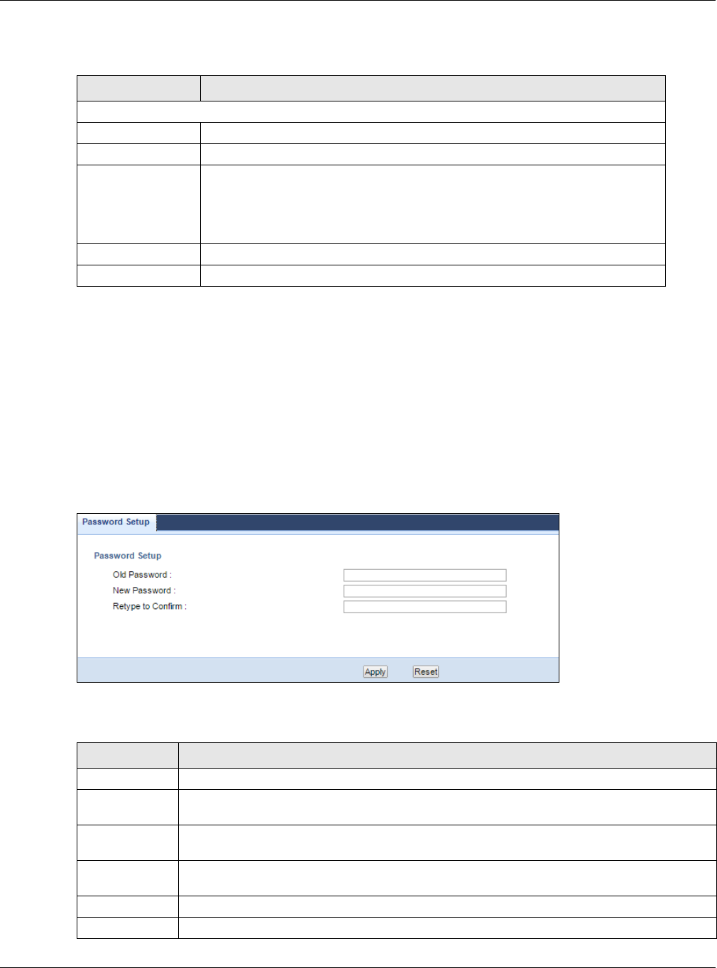
Chapter 25 Maintenance
NBG6515 User’s Guide
161
The following table describes the labels in this screen.
25.4 Password Screen
It is strongly recommended that you change your NBG's password.
If you forget your NBG's password (or IP address), you will need to reset the device. See Section
25.8 on page 166 for details.
Click Maintenance > Password. The screen appears as shown.
Figure 124 Maintenance > Password
The following table describes the labels in this screen.
Table 76 Maintenance > General
LABEL DESCRIPTION
System Setup
System Name System Name is a unique name to identify the NBG in an Ethernet network.
Domain Name Enter the domain name you want to give to the NBG.
Administrator
Inactivity Timer
Type how many minutes a management session can be left idle before the
session times out. The default is 5 minutes. After it times out you have to log in
with your password again. Very long idle timeouts may have security risks. A
value of "0" means a management session never times out, no matter how long
it has been left idle (not recommended).
Apply Click Apply to save your changes back to the NBG.
Reset Click Reset to return to the previously saved settings.
Table 77 Maintenance > Password
LABEL DESCRIPTION
Password Setup Change your NBG’s password (recommended) using the fields as shown.
Old Password Type the default password or the existing password you use to access the system in this
field.
New Password Type your new system password (up to 30 characters). Note that as you type a password,
the screen displays an asterisk (*) for each character you type.
Retype to
Confirm
Type the new password again in this field.
Apply Click Apply to save your changes back to the NBG.
Reset Click Reset to begin configuring this screen afresh.
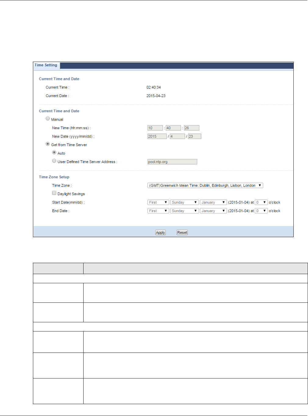
Chapter 25 Maintenance
NBG6515 User’s Guide
162
25.5 Time Setting Screen
Use this screen to configure the NBG’s time based on your local time zone. To change your NBG’s
time and date, click Maintenance > Time. The screen appears as shown.
Figure 125 Maintenance > Time
The following table describes the labels in this screen.
Table 78 Maintenance > Time
LABEL DESCRIPTION
Current Time and Date
Current Time This field displays the time of your NBG.
Each time you reload this page, the NBG synchronizes the time with the time server.
Current Date This field displays the date of your NBG.
Each time you reload this page, the NBG synchronizes the date with the time server.
Current Time and Date
Manual Select this radio button to enter the time and date manually. If you configure a new time
and date, Time Zone and Daylight Saving at the same time, the new time and date you
entered has priority and the Time Zone and Daylight Saving settings do not affect it.
New Time
(hh:mm:ss)
This field displays the last updated time from the time server or the last time configured
manually.
When you select Manual, enter the new time in this field and then click Apply.
New Date
(yyyy/mm/dd)
This field displays the last updated date from the time server or the last date configured
manually.
When you select Manual, enter the new date in this field and then click Apply.

Chapter 25 Maintenance
NBG6515 User’s Guide
163
25.6 Firmware Upgrade Screen
Find firmware at www.zyxel.com in a file that (usually) uses the system model name with a “*.bin”
extension, e.g., “NBG.bin”. The upload process uses HTTP (Hypertext Transfer Protocol) and may
take up to two minutes. After a successful upload, the system will reboot.
Click Maintenance > Firmware Upgrade. Follow the instructions in this screen to upload
firmware to your NBG.
Get from Time
Server
Select this radio button to have the NBG get the time and date from the time server you
specified below.
Auto Select Auto to have the NBG automatically search for an available time server and
synchronize the date and time with the time server after you click Apply.
User Defined Time
Server Address
Select User Defined Time Server Address and enter the IP address or URL (up to 20
extended ASCII characters in length) of your time server. Check with your ISP/network
administrator if you are unsure of this information.
Time Zone Setup
Time Zone Choose the time zone of your location. This will set the time difference between your time
zone and Greenwich Mean Time (GMT).
Daylight Savings Daylight saving is a period from late spring to early fall when many countries set their
clocks ahead of normal local time by one hour to give more daytime light in the evening.
Select this option if you use Daylight Saving Time.
Start Date (mm/
dd)
Configure the day and time when Daylight Saving Time starts if you selected Daylight
Savings. The o'clock field uses the 24 hour format. Here are a couple of examples:
Daylight Saving Time starts in most parts of the United States on the first Sunday of
April. Each time zone in the United States starts using Daylight Saving Time at 2 A.M.
local time. So in the United States you would select First, Sunday, April and select 2 in
the o'clock field.
Daylight Saving Time starts in the European Union on the last Sunday of March. All of the
time zones in the European Union start using Daylight Saving Time at the same moment
(1 A.M. GMT or UTC). So in the European Union you would select Last, Sunday, March.
The time you select in the o'clock field depends on your time zone. In Germany for
instance, you would select 2 because Germany's time zone is one hour ahead of GMT or
UTC (GMT+1).
End Date Configure the day and time when Daylight Saving Time ends if you selected Daylight
Savings. The o'clock field uses the 24 hour format. Here are a couple of examples:
Daylight Saving Time ends in the United States on the last Sunday of October. Each time
zone in the United States stops using Daylight Saving Time at 2 A.M. local time. So in the
United States you would select Last, Sunday, October and select 2 in the o'clock field.
Daylight Saving Time ends in the European Union on the last Sunday of October. All of the
time zones in the European Union stop using Daylight Saving Time at the same moment
(1 A.M. GMT or UTC). So in the European Union you would select Last, Sunday,
October. The time you select in the o'clock field depends on your time zone. In
Germany for instance, you would select 2 because Germany's time zone is one hour
ahead of GMT or UTC (GMT+1).
Apply Click Apply to save your changes back to the NBG.
Reset Click Reset to begin configuring this screen afresh.
Table 78 Maintenance > Time (continued)
LABEL DESCRIPTION
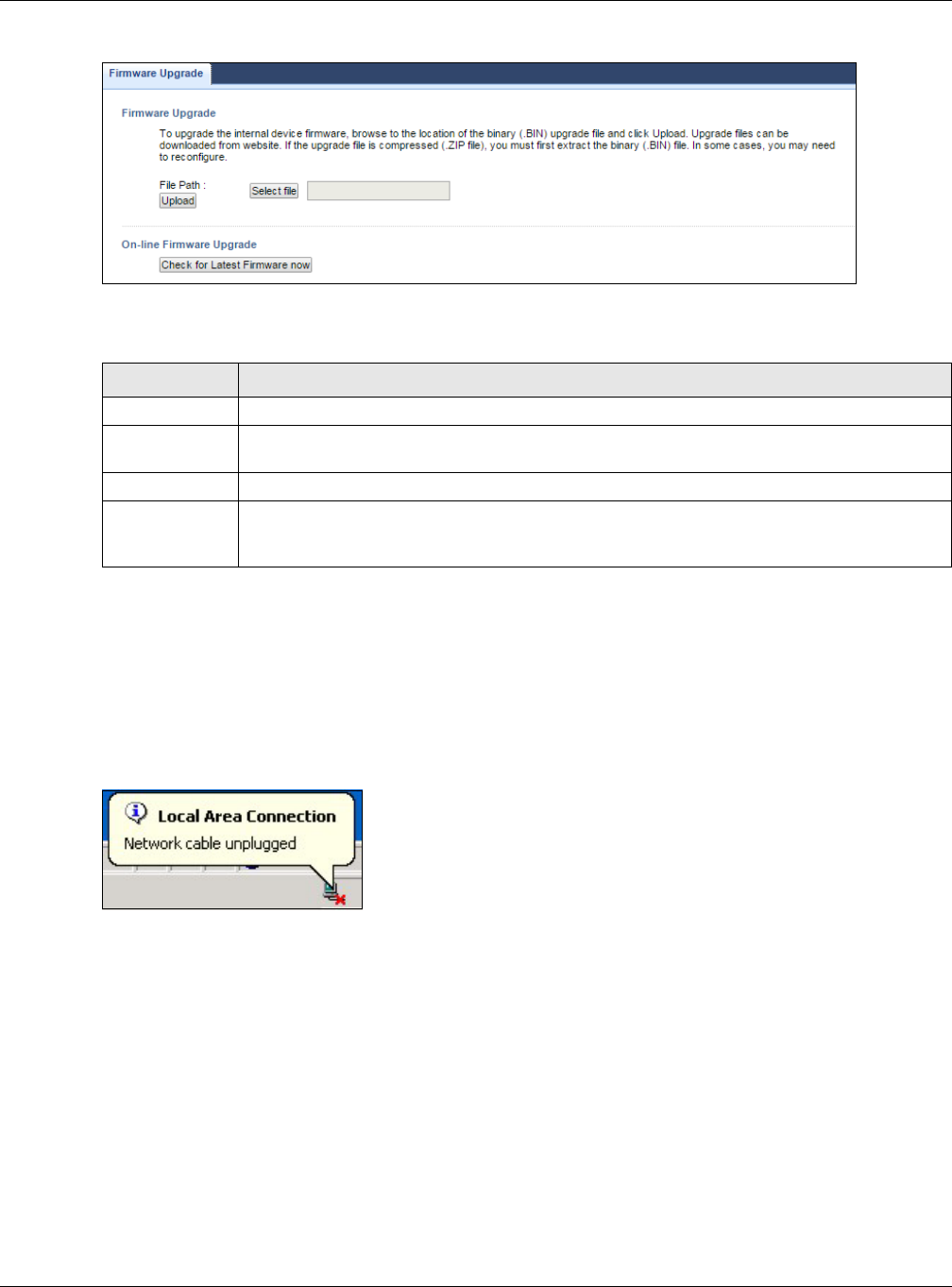
Chapter 25 Maintenance
NBG6515 User’s Guide
164
Figure 126 Maintenance > Firmware Upgrade
The following table describes the labels in this screen.
Note: Do not turn off the NBG while firmware upload is in progress!
After you see the Firmware Upload In Process screen, wait two minutes before logging into the
NBG again.
The NBG automatically restarts in this time causing a temporary network disconnect. In some
operating systems, you may see the following icon on your desktop.
Figure 127 Network Temporarily Disconnected
After two minutes, log in again and check your new firmware version in the Status screen.
If the upload was not successful, an error message appears. Click Return to go back to the
Firmware Upgrade screen.
25.7 Configuration Backup/Restore Screen
Backup configuration allows you to back up (save) the NBG’s current configuration to a file on your
computer. Once your NBG is configured and functioning properly, it is highly recommended that you
back up your configuration file before making configuration changes. The backup configuration file
will be useful in case you need to return to your previous settings.
Table 79 Maintenance > Firmware Upgrade
LABEL DESCRIPTION
File Path Type in the location of the file you want to upload in this field or click Select file to find it.
Select file Click Select file to find the .bin file you want to upload. Remember that you must
decompress compressed (.zip) files before you can upload them.
Upload Click Upload to begin the upload process. This process may take up to two minutes.
Check for
Latest
Firmware Now
Click this to check for the latest updated firmware.
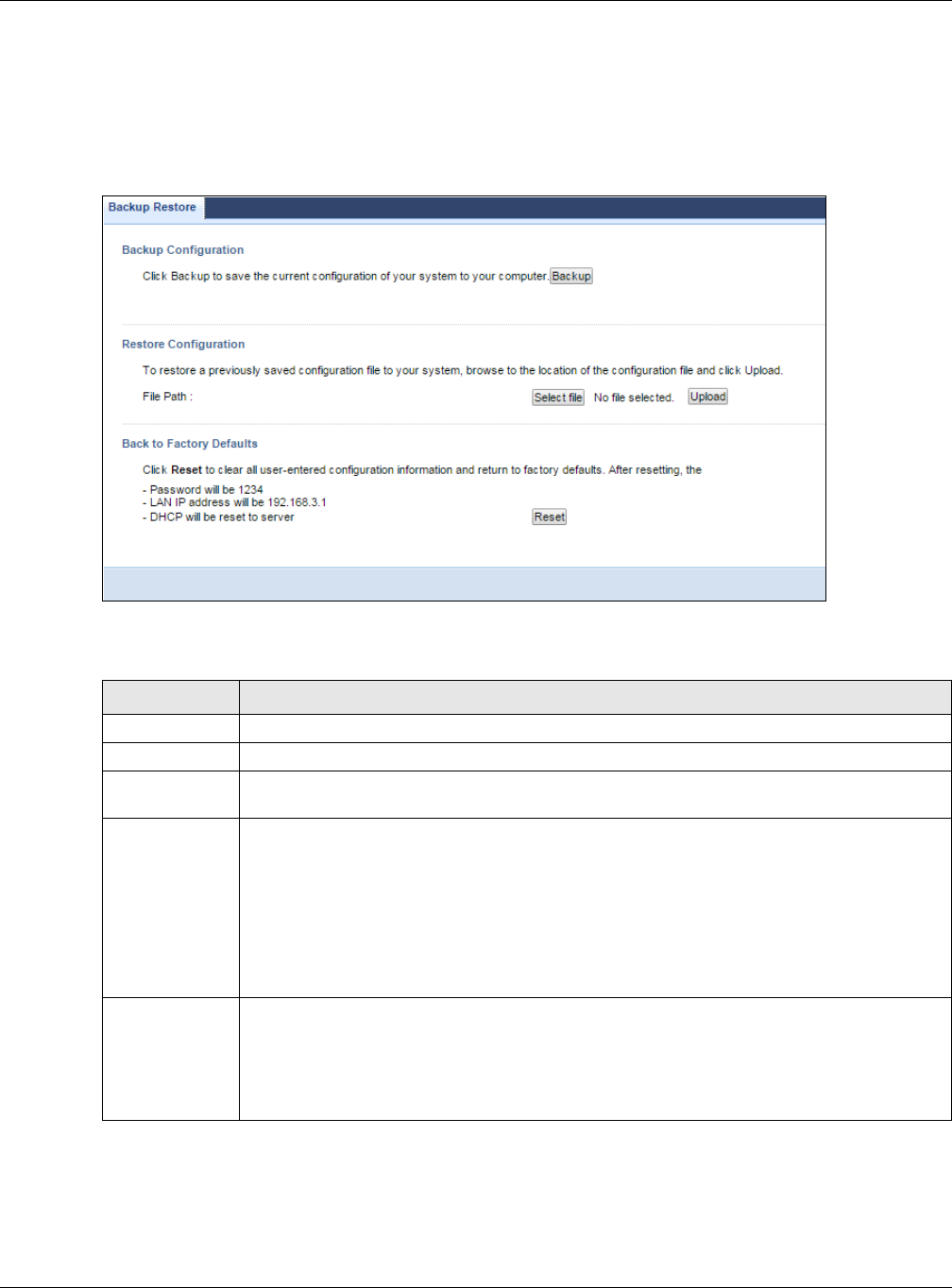
Chapter 25 Maintenance
NBG6515 User’s Guide
165
Restore configuration allows you to upload a new or previously saved configuration file from your
computer to your NBG.
Click Maintenance > Backup/Restore. Information related to factory defaults, backup
configuration, and restoring configuration appears as shown next.
Figure 128 Maintenance > Backup/Restore
The following table describes the labels in this screen.
Note: If you uploaded the default configuration file you may need to change the IP
address of your computer to be in the same subnet as that of the default NBG IP
address (192.168.1.2). See Appendix C on page 191 for details on how to set up
your computer’s IP address.
Table 80 Maintenance > Backup/Restore
LABEL DESCRIPTION
Backup Click Backup to save the NBG’s current configuration to your computer.
File Path Type in the location of the file you want to upload in this field or click Browse... to find it.
Select file Click Select file to find the file you want to upload. Remember that you must decompress
compressed (.ZIP) files before you can upload them.
Upload Click Upload to begin the upload process.
Note: Do not turn off the NBG while configuration file upload is in progress.
After you see a “configuration upload successful” screen, you must then wait one minute
before logging into the NBG again. The NBG automatically restarts in this time causing a
temporary network disconnect.
If you see an error screen, click Back to return to the Backup/Restore screen.
Reset Pressing the Reset button in this section clears all user-entered configuration information
and returns the NBG to its factory defaults.
You can also press the RESET button on the rear panel to reset the factory defaults of your
NBG. Refer to the chapter about introducing the Web Configurator for more information on
the RESET button.
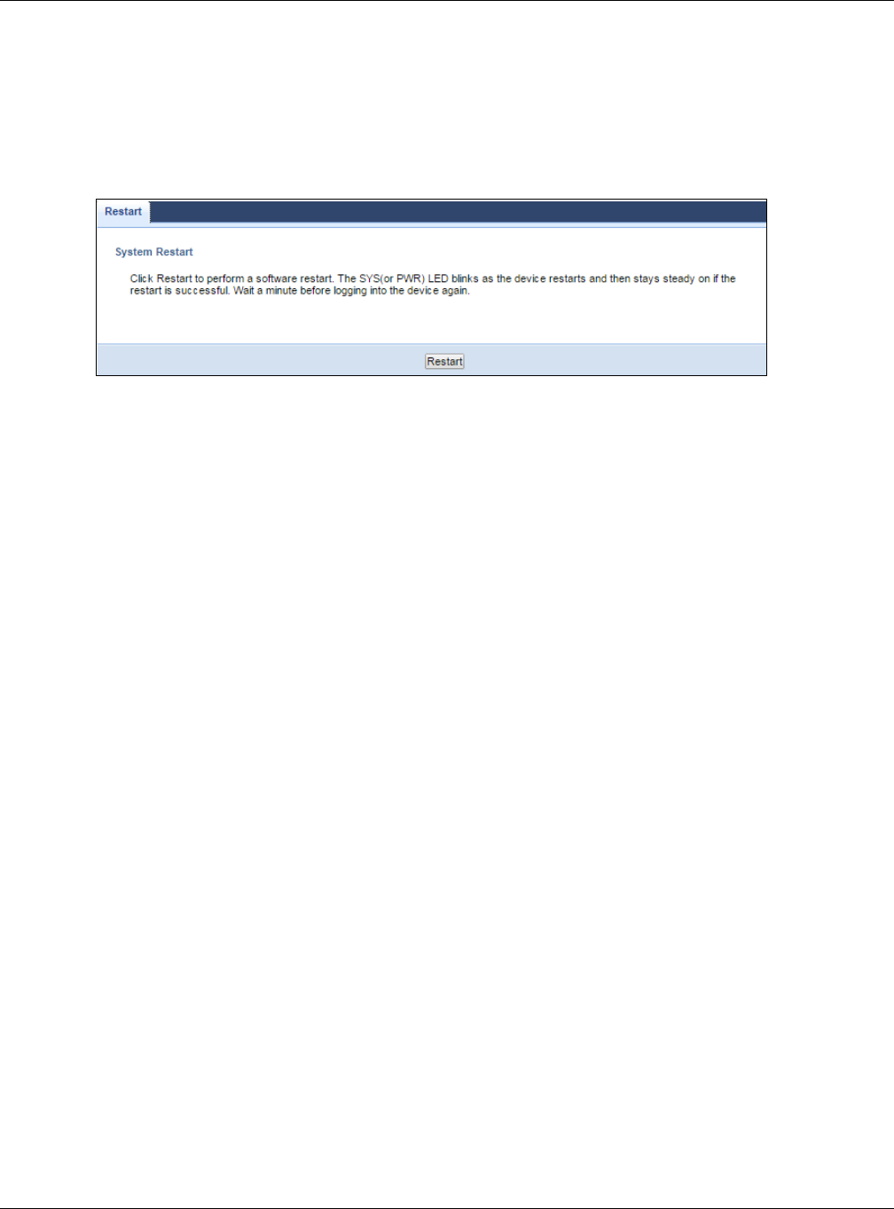
Chapter 25 Maintenance
NBG6515 User’s Guide
166
25.8 Restart Screen
System restart allows you to reboot the NBG without turning the power off.
Click Maintenance > Restart to open the following screen.
Figure 129 Maintenance > Restart
Click Restart to have the NBG reboot. This does not affect the NBG's configuration.

NBG6515 User’s Guide
167
CHAPTER 26
Troubleshooting
This chapter offers some suggestions to solve problems you might encounter. The potential
problems are divided into the following categories.
•Power, Hardware Connections, and LEDs
•NBG Access and Login
•Internet Access
•Resetting the NBG to Its Factory Defaults
•Wireless Router/AP Troubleshooting
•USB Device Problems
26.1 Power, Hardware Connections, and LEDs
The NBG does not turn on. None of the LEDs turn on.
1Make sure you are using the power adaptor or cord included with the NBG.
2Make sure the power adaptor or cord is connected to the NBG and plugged in to an appropriate
power source. Make sure the power source is turned on.
3Disconnect and re-connect the power adaptor or cord to the NBG.
4If the problem continues, contact the vendor.
One of the LEDs does not behave as expected.
1Make sure you understand the normal behavior of the LED. See Section 1.5 on page 14.
2Check the hardware connections. See the Quick Start Guide.
3Inspect your cables for damage. Contact the vendor to replace any damaged cables.
4Disconnect and re-connect the power adaptor to the NBG.
5If the problem continues, contact the vendor.

Chapter 26 Troubleshooting
NBG6515 User’s Guide
168
26.2 NBG Access and Login
I don’t know the IP address of my NBG.
1The default IP address is 192.168.1.1.
2If you changed the IP address and have forgotten it, you might get the IP address of the NBG by
looking up the IP address of the default gateway for your computer. To do this in most Windows
computers, click Start > Run, enter cmd, and then enter ipconfig. The IP address of the Default
Gateway might be the IP address of the NBG (it depends on the network), so enter this IP address
in your Internet browser.Set your device to Router Mode, login (see the Quick Start Guide for
instructions) and go to the Device Information table in the Status screen. Your NBG’s IP address
is available in the Device Information table.
•If the DHCP setting under LAN information is None, your device has a fixed IP address.
•If the DHCP setting under LAN information is Client, then your device receives an IP
address from a DHCP server on the network.
3If your NBG is a DHCP client, you can find your IP address from the DHCP server. This information is
only available from the DHCP server which allocates IP addresses on your network. Find this
information directly from the DHCP server or contact your system administrator for more
information.
4Reset your NBG to change all settings back to their default. This means your current settings are
lost. See Section 26.4 on page 171 in the Troubleshooting for information on resetting your NBG.
I forgot the password.
1The default password is 1234.
2If this does not work, you have to reset the device to its factory defaults. See Section 26.4 on page
171.
I cannot see or access the Login screen in the Web Configurator.
1Make sure you are using the correct IP address.
• The default IP address is 192.168.1.1.
• If you changed the IP address (Section 14.4 on page 112), use the new IP address.
• If you changed the IP address and have forgotten it, see the troubleshooting suggestions for I
don’t know the IP address of my NBG.
2Check the hardware connections, and make sure the LEDs are behaving as expected. See the Quick
Start Guide.

Chapter 26 Troubleshooting
NBG6515 User’s Guide
169
3Make sure your Internet browser does not block pop-up windows and has JavaScript and Java
enabled. See Appendix A on page 173.
4Make sure your computer is in the same subnet as the NBG. (If you know that there are routers
between your computer and the NBG, skip this step.)
• If there is a DHCP server on your network, make sure your computer is using a dynamic IP
address. See Appendix C on page 191.
• If there is no DHCP server on your network, make sure your computer’s IP address is in the
same subnet as the NBG. See Appendix C on page 191.
5Reset the device to its factory defaults, and try to access the NBG with the default IP address. See
Section 3.3 on page 30.
6If the problem continues, contact the network administrator or vendor, or try one of the advanced
suggestions.
Advanced Suggestion
• If your computer is connected to the WAN port or is connected wirelessly, use a computer that is
connected to a LAN/ETHERNET port.
I can see the Login screen, but I cannot log in to the NBG.
1Make sure you have entered the password correctly. The default password is 1234. This field is
case-sensitive, so make sure [Caps Lock] is not on.
2This can happen when you fail to log out properly from your last session. Try logging in again after
5 minutes.
3Disconnect and re-connect the power adaptor or cord to the NBG.
4If this does not work, you have to reset the device to its factory defaults. See Section 26.4 on page
171.
26.3 Internet Access
I cannot access the Internet.
1Check the hardware connections, and make sure the LEDs are behaving as expected. See the Quick
Start Guide.
2Make sure you entered your ISP account information correctly in the wizard. These fields are case-
sensitive, so make sure [Caps Lock] is not on.

Chapter 26 Troubleshooting
NBG6515 User’s Guide
170
3If you are trying to access the Internet wirelessly, make sure the wireless settings in the wireless
client are the same as the settings in the AP.
4Disconnect all the cables from your device, and follow the directions in the Quick Start Guide again.
5Check your System Operation Mode setting.
•Select Router if your device routes traffic between a local network and another network such
as the Internet.
•Select Access Point if your device bridges traffic between clients on the same network.
•Select Universal Repeater Mode if your device is wirelessly connected to an access point or
wireless router with Internet access. Your computer should be set to obtain an dynamic IP
address.
6Disconnect all the cables from your device, and follow the directions in the Quick Start Guide again.
7If the problem continues, contact your ISP.
I cannot access the Internet anymore. I had access to the Internet (with the NBG), but my
Internet connection is not available anymore.
1Check the hardware connections, and make sure the LEDs are behaving as expected. See the Quick
Start Guide and Section 1.5 on page 14.
2Reboot the NBG.
3If the problem continues, contact your ISP.
The Internet connection is slow or intermittent.
1There might be a lot of traffic on the network. Look at the LEDs, and check Section 1.5 on page 14.
If the NBG is sending or receiving a lot of information, try closing some programs that use the
Internet, especially peer-to-peer applications.
2Check the signal strength. If the signal strength is low, try moving the NBG closer to the AP if
possible, and look around to see if there are any devices that might be interfering with the wireless
network (for example, microwaves, other wireless networks, and so on).
3Reboot the NBG.
4If the problem continues, contact the network administrator or vendor, or try one of the advanced
suggestions.
Advanced Suggestions
• Check the settings for bandwidth management. If it is disabled, you might consider activating it.
If it is enabled, you might consider changing the allocations.

Chapter 26 Troubleshooting
NBG6515 User’s Guide
171
• Check the settings for QoS. If it is disabled, you might consider activating it. If it is enabled, you
might consider raising or lowering the priority for some applications.
I set up URL keyword blocking, but I can still access a website that should be blocked.
Make sure that you select the Enable URL Keyword Blocking check box in the Content Filtering
screen. Make sure that the keywords that you type are listed in the Keyword List.
If a keyword that is listed in the Keyword List is not blocked when it is found in a URL, customize
the keyword blocking using commands. See the Customizing Keyword Blocking URL Checking
section in the Content Filter chapter.
26.4 Resetting the NBG to Its Factory Defaults
If you reset the NBG, you lose all of the changes you have made. The NBG re-loads its default
settings, and the password resets to 1234. You have to make all of your changes again.
You will lose all of your changes when you push the RESET button.
To reset the NBG,
1Make sure the power LED is on.
2Press the RESET button for longer than 1 second to restart/reboot the NBG.
3Press the RESET button for longer than five seconds to set the NBG back to its factory-default
configurations.
If the NBG restarts automatically, wait for the NBG to finish restarting, and log in to the Web
Configurator. The password is “1234”.
If the NBG does not restart automatically, disconnect and reconnect the NBG’s power. Then, follow
the directions above again.
26.5 Wireless Router/AP Troubleshooting
I cannot access the NBG or ping any computer from the WLAN (wireless AP or router).
1Make sure the wireless LAN is enabled on the NBG

Chapter 26 Troubleshooting
NBG6515 User’s Guide
172
2Make sure the wireless adapter on the wireless station is working properly.
3Make sure the wireless adapter installed on your computer is IEEE 802.11 compatible and supports
the same wireless standard as the NBG.
4Make sure your computer (with a wireless adapter installed) is within the transmission range of the
NBG.
5Check that both the NBG and your wireless station are using the same wireless and wireless
security settings.
6Make sure traffic between the WLAN and the LAN is not blocked by the firewall on the NBG.
7Make sure you allow the NBG to be remotely accessed through the WLAN interface. Check your
remote management settings.
• See the chapter on Wireless LAN in the User’s Guide for more information.
I cannot access the Web Configurator after I switched to AP mode.
192.168.1.1 is the default IP in Router mode (the default mode). In AP mode the default IP is
192.168.1.2. So, when you switch from Router mode to AP mode, you need to use the AP mode IP to
log in.
26.6 USB Device Problems
I cannot access or see a USB device that is connected to the NBG.
1Be sure to install the ZyXEL NetUSB Share Center Utility (for NetUSB functionality) first from the
included disc, or download the latest version from the zyxel.com website.
2Disconnect the problematic USB device, then reconnect it to the NBG.
3Ensure that the USB device has power.
4Check your cable connections.
5Restart the NBG by disconnecting the power and then reconnecting it.
6If the USB device requires a special driver, install the driver from the installation disc that came
with the device. After driver installation, reconnect the USB device to the NBG and try to connect to
it again with your computer.
7If the problem persists, contact your vendor.

Chapter 26 Troubleshooting
NBG6515 User’s Guide
173
What kind of USB devices do the NBG support?
1It is strongly recommended to use version 2.0 or lower USB storage devices (such as memory
sticks, USB hard drives) and/or USB devices (such as USB printers). Other USB products are not
guaranteed to function properly with the NBG.