ZyXEL Communications NBG6617 AC1300 MU-MIMO Dual-Band Wireless Gigabit Router User Manual Book
ZyXEL Communications Corporation AC1300 MU-MIMO Dual-Band Wireless Gigabit Router Book
Contents
- 1. User Manual Part 1 (1-98).pdf
- 2. User Manual Part 2 (99-105).pdf
User Manual Part 2 (99-105).pdf
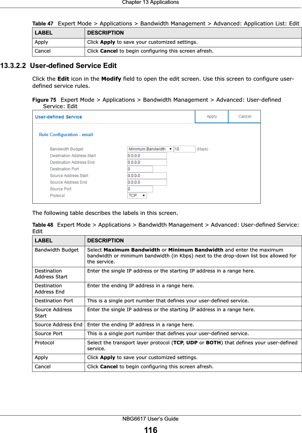
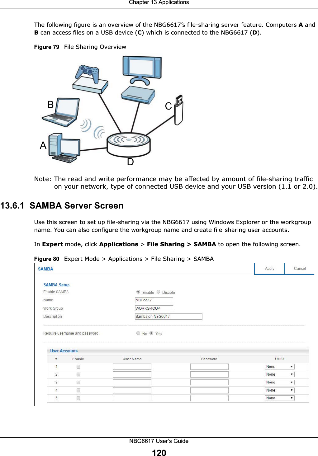
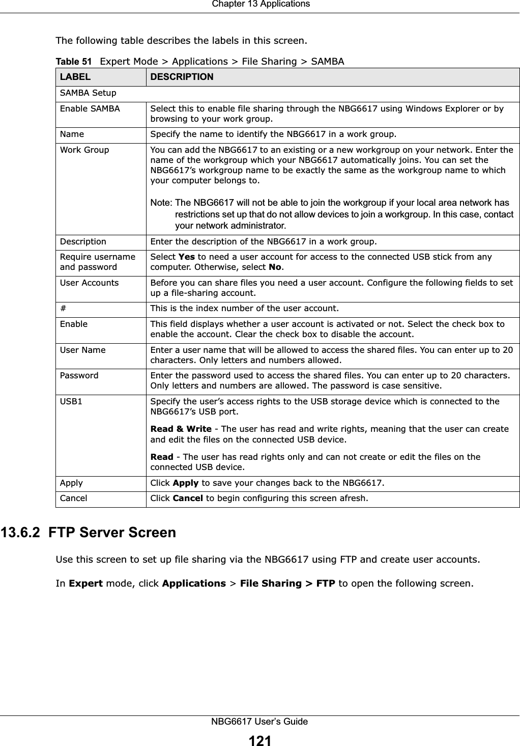
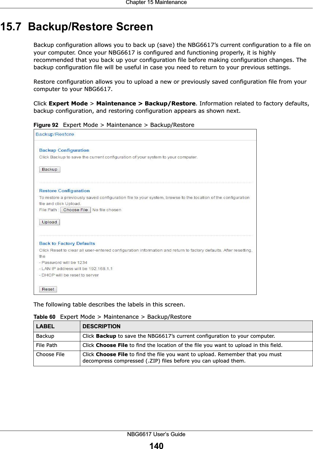
![Chapter 13 ApplicationsNBG6617 User’s Guide12313.6.3 Example of Accessing Your Shared Files From a Computer You can use Windows Explorer or FTP to access the USB storage devices connected to the NBG6617.This example shows you how to use Microsoft’s Windows XP to browse your shared files. Refer to your operating system’s documentation for how to browse your file structure. Use Windows Explorer to Share Files You should have enabled file sharing and create a user account (Bob/1234 for example) with read and write access to USB 1 in the Applications > File Sharing > SAMBA screen.Open Windows Explorer to access the connected USB device using either Windows Explorer browser or by browsing to your workgroup.1In Windows Explorer’s Address bar type a double backslash “\\” followed by the IP address of the NBG6617 (the default IP address of the NBG6617 in router mode is 192.168.1.1) and press [ENTER]. A screen asking for password authentication appears. Type the user name and password (Bob and 1234 in this example) and click OK.Note: Once you log into the shared folder via your NBG6617, you do not have to relogin unless you restart your computer.](https://usermanual.wiki/ZyXEL-Communications/NBG6617.User-Manual-Part-2-99-105-pdf/User-Guide-3078003-Page-25.png)
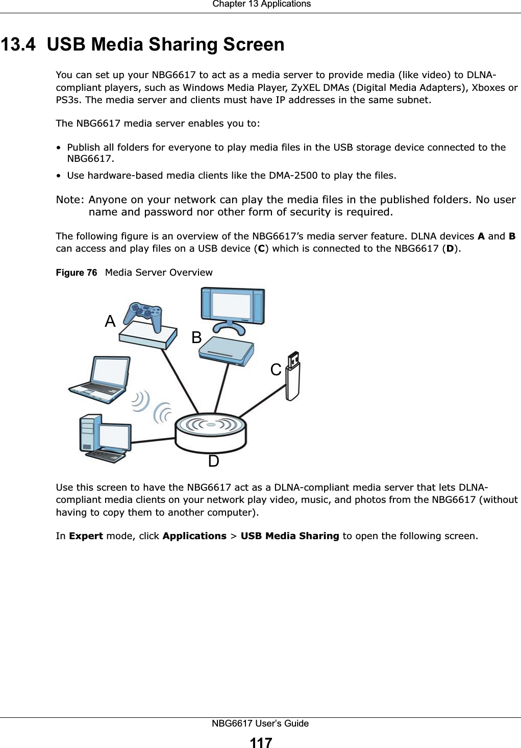
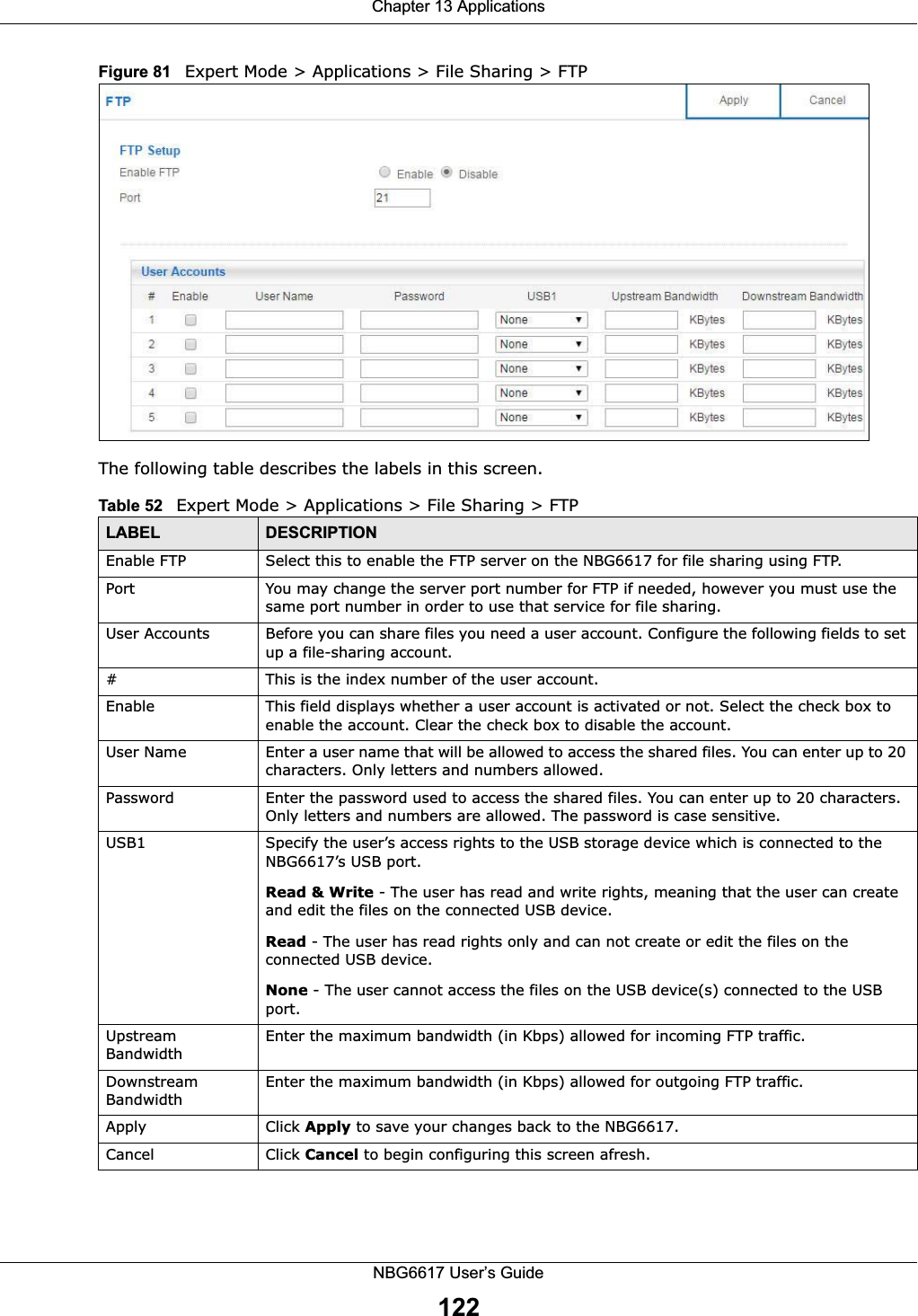
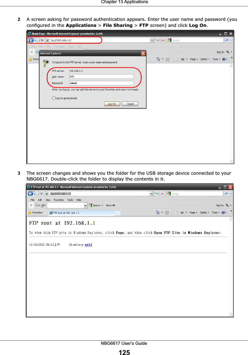
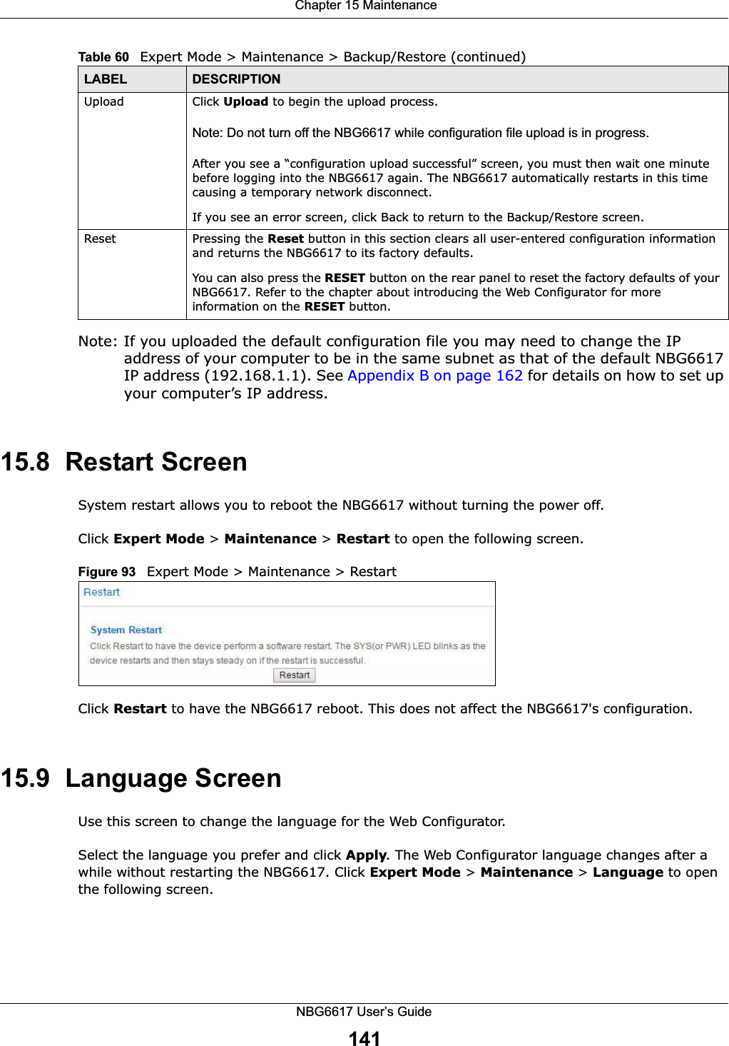
![Chapter 13 ApplicationsNBG6617 User’s Guide1242You can also use the workgroup name to access files by browsing to the workgroup folder using the folder tree on the left side of the screen. It is located under My Network Places. In this example the workgroup name is the default “Workgroup”. Use FTP to Share FilesYou can use FTP to access the USB storage devices connected to the NBG6617. In this example, we use the web browser to share files via FTP from the LAN. The way or screen you log into the FTP server (on the NBG6617) varies depending on your FTP client. See your FTP client documentation for more information. You should have enabled file sharing and create a user account (Bob/1234 for example) with read and write access to USB 1 in the Applications > File Sharing > FTP screen.1In your web browser’s address or URL bar type “ftp://” followed by the IP address of the NBG6617 (the default LAN IP address of the NBG6617 in router mode is 192.168.1.1) and click Go or press [ENTER].](https://usermanual.wiki/ZyXEL-Communications/NBG6617.User-Manual-Part-2-99-105-pdf/User-Guide-3078003-Page-26.png)
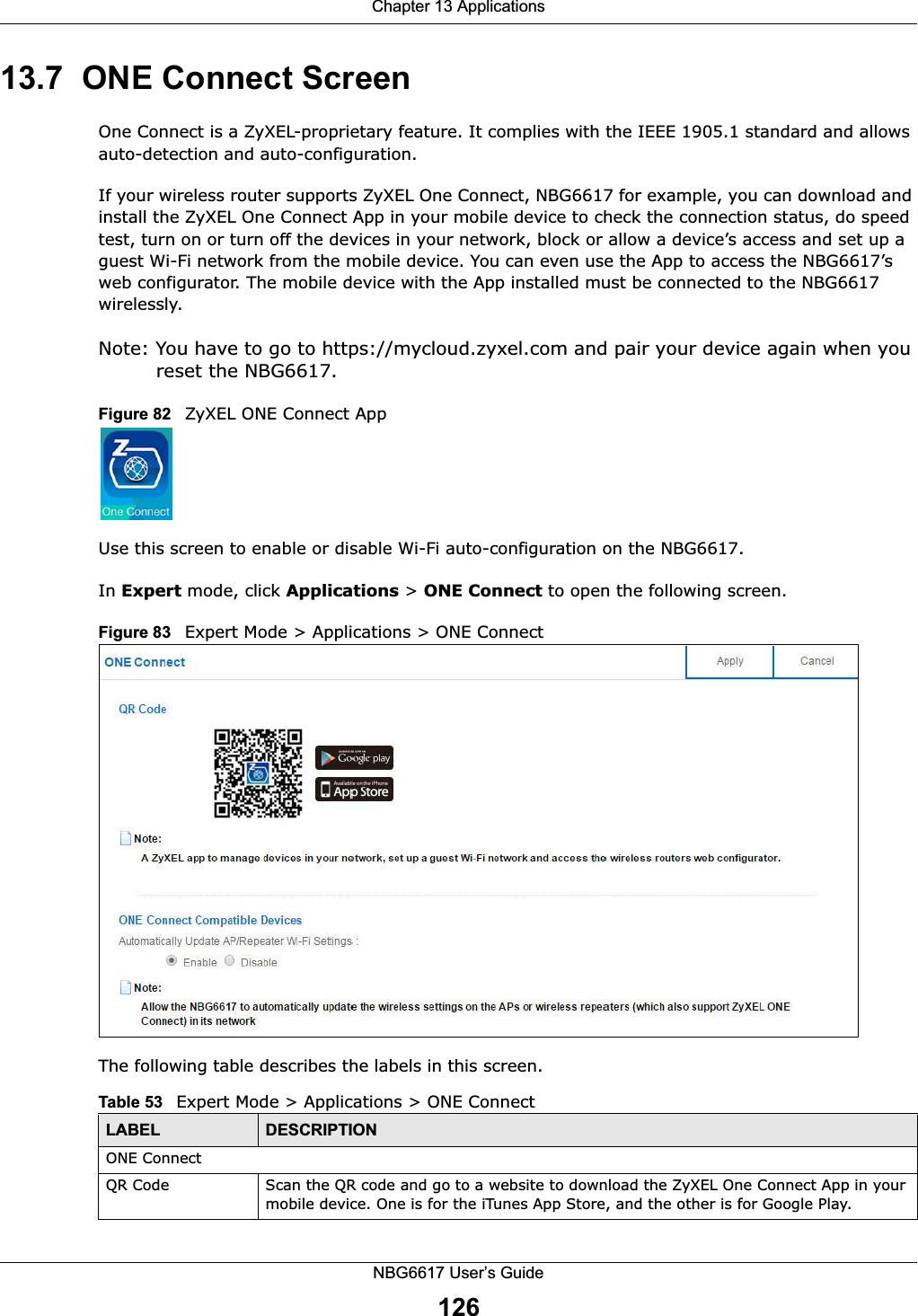
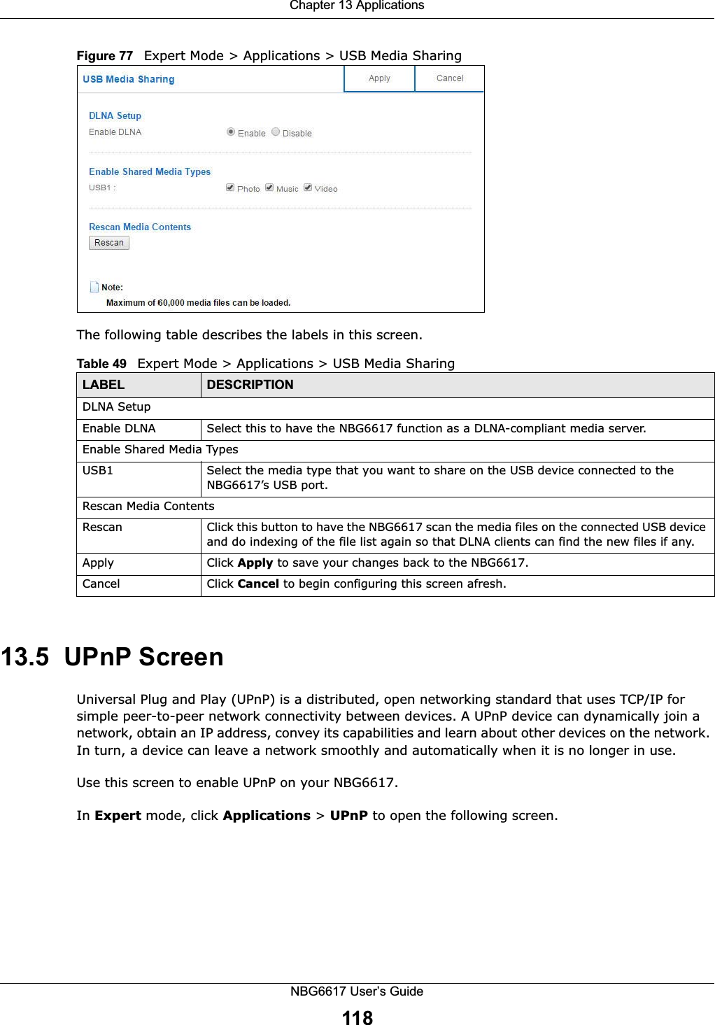
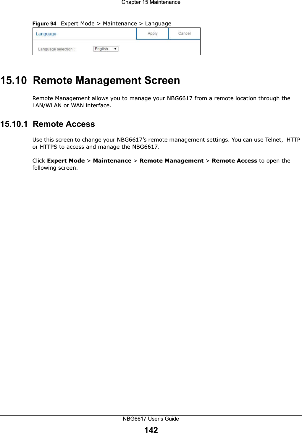
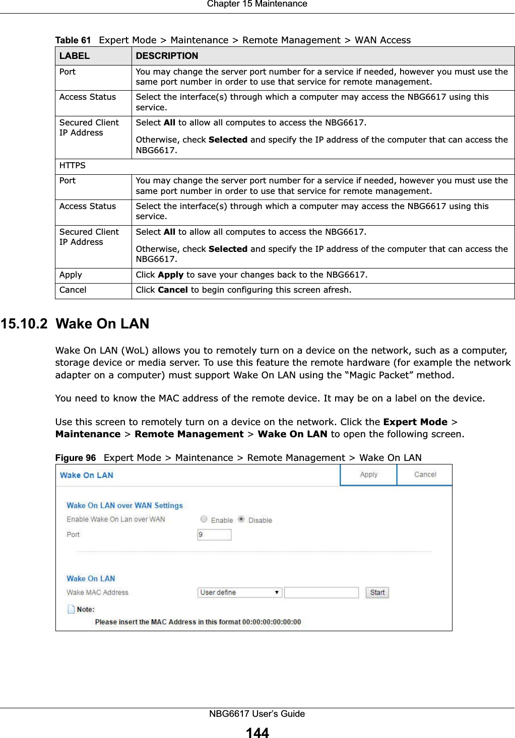
![Chapter 13 ApplicationsNBG6617 User’s Guide12713.8 Technical ReferenceThe following section contains additional technical information about the NBG6617 features described in this chapter.Customizing Keyword Blocking URL CheckingYou can use commands to set how much of a website’s URL the content filter is to check for keyword blocking. See the appendices for information on how to access and use the command interpreter.Domain Name or IP Address URL CheckingBy default, the NBG6617 checks the URL’s domain name or IP address when performing keyword blocking.This means that the NBG6617 checks the characters that come before the first slash in the URL.For example, with the URL www.zyxel.com.tw/news/pressroom.php, content filtering only searches for keywords within www.zyxel.com.tw.Full Path URL CheckingFull path URL checking has the NBG6617 check the characters that come before the last slash in the URL.For example, with the URL www.zyxel.com.tw/news/pressroom.php, full path URL checking searches for keywords within www.zyxel.com.tw/news/.Use the ip urlfilter customize actionFlags 6 [disable | enable] command to extend (or not extend) the keyword blocking search to include the URL's full path.File Name URL CheckingFilename URL checking has the NBG6617 check all of the characters in the URL.For example, filename URL checking searches for keywords within the URL www.zyxel.com.tw/news/pressroom.php.One Connect Compatible DevicesAutomatically Update AP/Repeater Wi-Fi SettingsSelect Enable to allow the NBG6617 to automatically update the wireless settings on the APs or wireless repeaters (which also support ZyXEL One Connect) in its network. Select Disable to turn this feature off if you want to have the APs or repeaters in the network use different wireless settings.Apply Click Apply to save your changes back to the NBG6617.Cancel Click Cancel to begin configuring this screen afresh.Table 53 Expert Mode > Applications > ONE Connect LABEL DESCRIPTION](https://usermanual.wiki/ZyXEL-Communications/NBG6617.User-Manual-Part-2-99-105-pdf/User-Guide-3078003-Page-29.png)
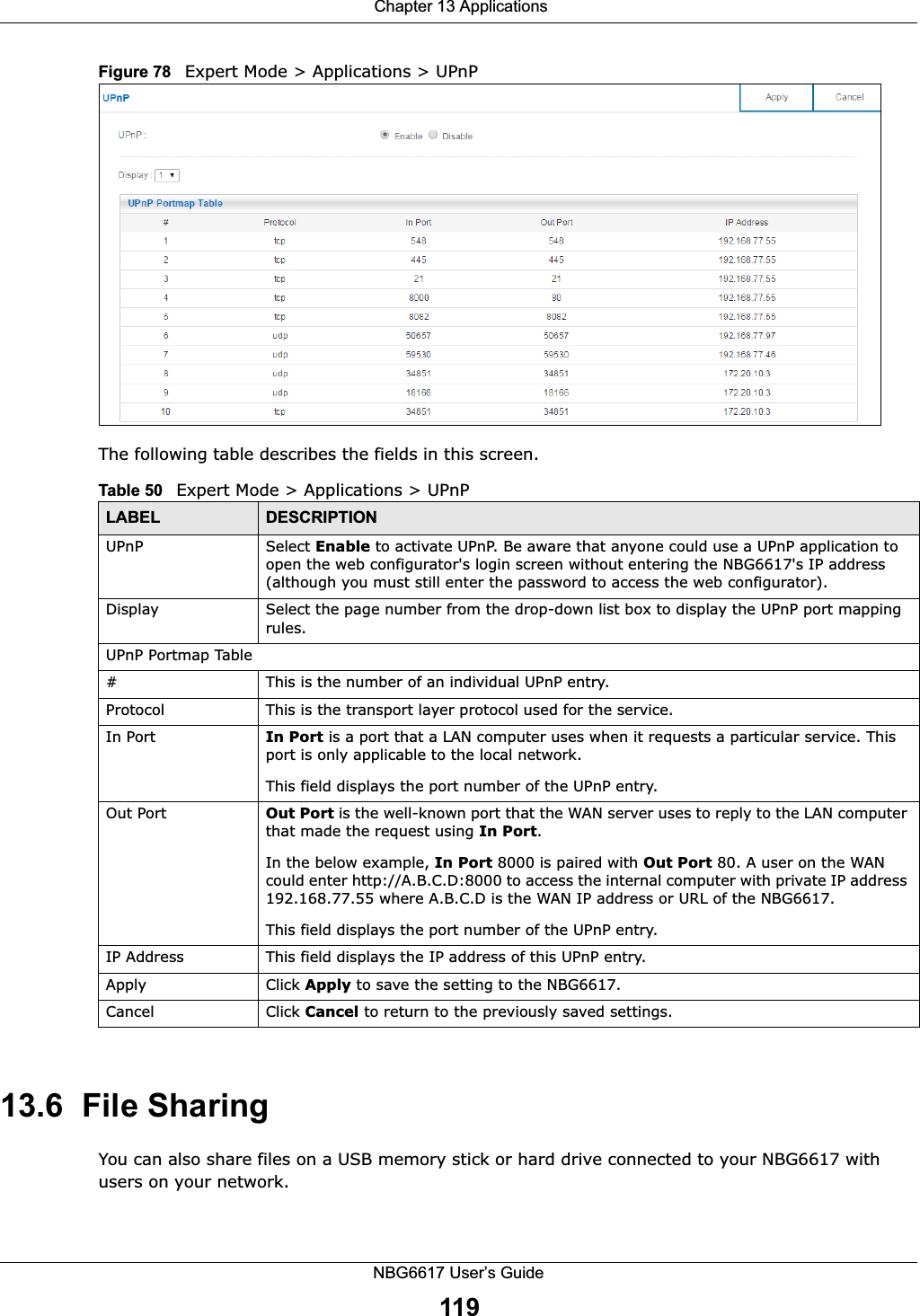
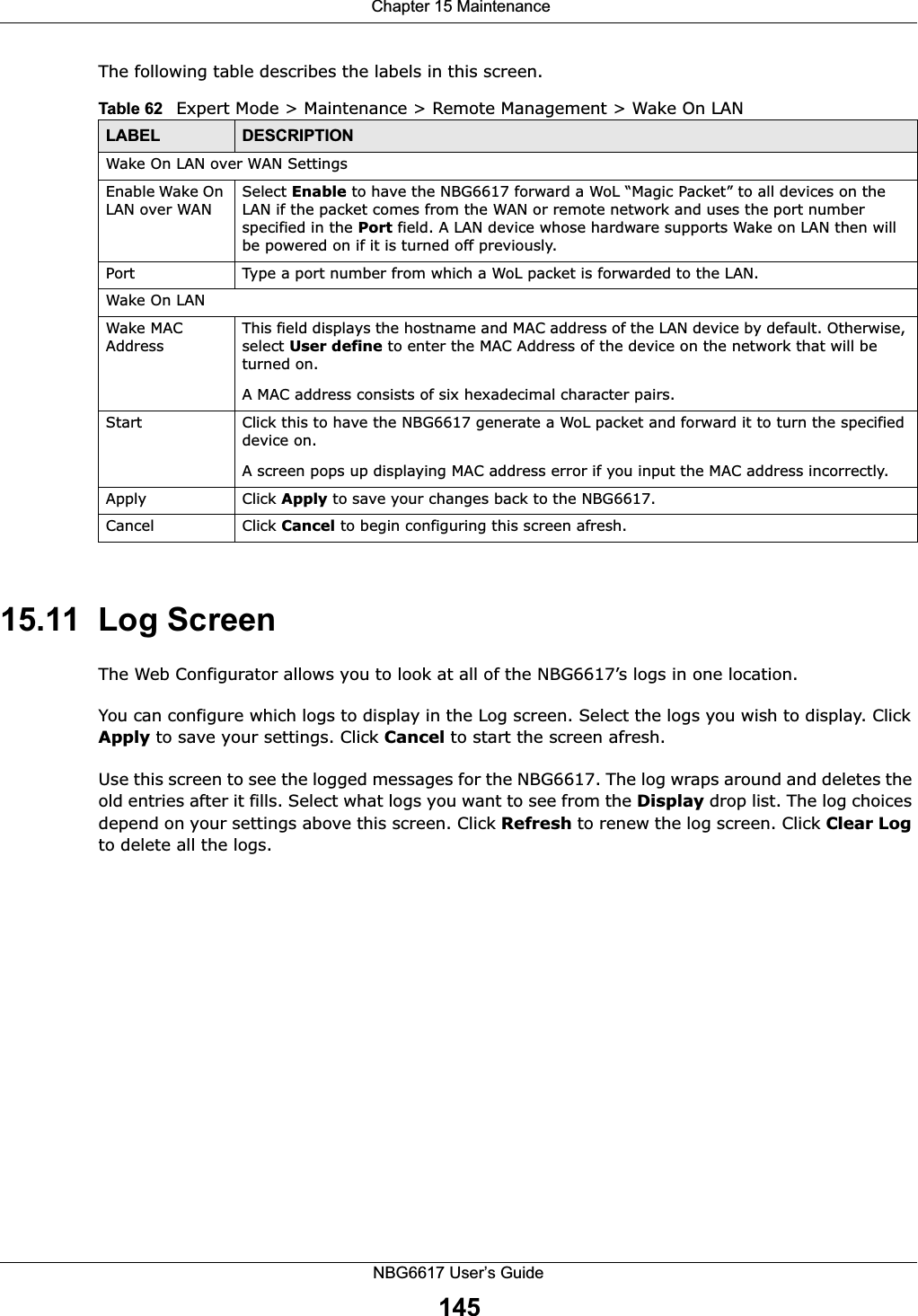
![Chapter 13 ApplicationsNBG6617 User’s Guide128Use the ip urlfilter customize actionFlags 8 [disable | enable] command to extend (or not extend) the keyword blocking search to include the URL's complete filename.NAT TraversalUPnP NAT traversal automates the process of allowing an application to operate through NAT. UPnP network devices can automatically configure network addressing, announce their presence in the network to other UPnP devices and enable exchange of simple product and service descriptions. NAT traversal allows the following:• Dynamic port mapping• Learning public IP addresses• Assigning lease times to mappingsWindows Messenger is an example of an application that supports NAT traversal and UPnP. See the NAT chapter for more information on NAT.Cautions with UPnPThe automated nature of NAT traversal applications in establishing their own services and opening firewall ports may present network security issues. Network information and configuration may also be obtained and modified by users in some network environments. When a UPnP device joins a network, it announces its presence with a multicast message. For security reasons, the NBG6617 allows multicast messages on the LAN only.All UPnP-enabled devices may communicate freely with each other without additional configuration. Disable UPnP if this is not your intention.](https://usermanual.wiki/ZyXEL-Communications/NBG6617.User-Manual-Part-2-99-105-pdf/User-Guide-3078003-Page-30.png)
![Chapter 16 TroubleshootingNBG6617 User’s Guide151• If you changed the IP address and have forgotten it, see the troubleshooting suggestions for I don’t know the IP address of my NBG6617.3Check the hardware connections, and make sure the LEDs are behaving as expected. See the Quick Start Guide. 4Make sure your Internet browser does not block pop-up windows and has JavaScript and Java enabled. 5Make sure your computer is in the same subnet as the NBG6617. (If you know that there are routers between your computer and the NBG6617, skip this step.)• If there is a DHCP server on your network, make sure your computer is using a dynamic IP address. See Section 12.4 on page 100. • If there is no DHCP server on your network, make sure your computer’s IP address is in the same subnet as the NBG6617. See Section 12.4 on page 100.6Reset the device to its factory defaults, and try to access the NBG6617 with the default IP address. See Section 1.5 on page 11.7If the problem continues, contact the network administrator or vendor, or try one of the advanced suggestions.Advanced Suggestions• Try to access the NBG6617 using another service, such as Telnet. If you can access the NBG6617, check the remote management settings and firewall rules to find out why the NBG6617 does not respond to HTTP.• If your computer is connected to the WAN port or is connected wirelessly, use a computer that is connected to a LAN/ETHERNET port.I can see the Login screen, but I cannot log in to the NBG6617.1Make sure you have entered the password correctly. The default password is 1234. This field is case-sensitive, so make sure [Caps Lock] is not on. 2This can happen when you fail to log out properly from your last session. Try logging in again after 5 minutes.3Disconnect and re-connect the power adaptor or cord to the NBG6617. 4If this does not work, you have to reset the device to its factory defaults. See Section 16.5 on page 153.16.4 Internet AccessI cannot access the Internet.](https://usermanual.wiki/ZyXEL-Communications/NBG6617.User-Manual-Part-2-99-105-pdf/User-Guide-3078003-Page-53.png)
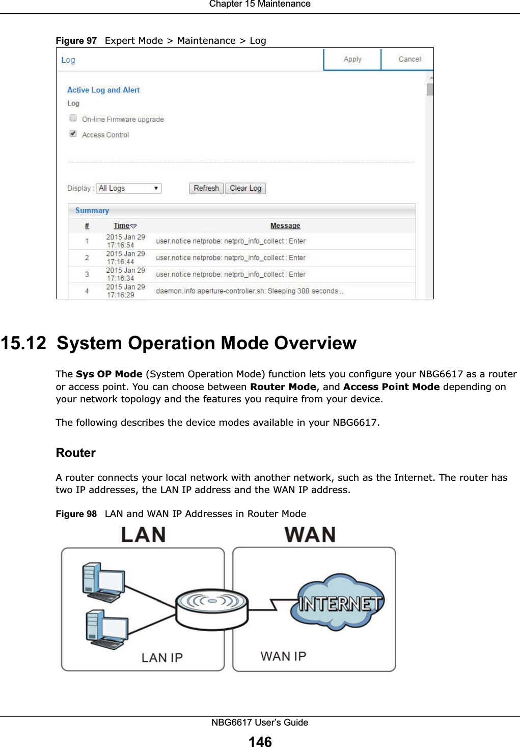
![Chapter 16 TroubleshootingNBG6617 User’s Guide1521Check the hardware connections, and make sure the LEDs are behaving as expected. See the Quick Start Guide.2Go to Expert > Maintenance > Operation Mode. Check your System Operation Mode setting. • If the NBG6617 is in Router Mode, make sure the WAN port is connected to a broadband modem or router with Internet access. Your computer and the NBG6617 should be in the same subnet.• If the NBG6617 is in Access Point Mode, make sure the WAN port is connected to a broadband modem or router with Internet access and your computer is set to obtain an dynamic IP address.3If the NBG6617 is in Router Mode, make sure you entered your ISP account information correctly in the wizard or the WAN screen. These fields are case-sensitive, so make sure [Caps Lock] is not on.4If you are trying to access the Internet wirelessly, make sure the wireless settings in the wireless client are the same as the settings in the AP.5Disconnect all the cables from your device, and follow the directions in the Quick Start Guide again. 6If the problem continues, contact your ISP.I cannot access the Internet anymore. I had access to the Internet (with the NBG6617), but my Internet connection is not available anymore.1Check the hardware connections, and make sure the LEDs are behaving as expected. See the Quick Start Guide and Section 1.7 on page 12. 2Reboot the NBG6617.3If the problem continues, contact your ISP. The Internet connection is slow or intermittent.1There might be a lot of traffic on the network. Look at the LEDs, and check Section 1.7 on page 12. If the NBG6617 is sending or receiving a lot of information, try closing some programs that use the Internet, especially peer-to-peer applications.2Check the signal strength. If the signal strength is low, try moving the NBG6617 closer to the AP if possible, and look around to see if there are any devices that might be interfering with the wireless network (for example, microwaves, other wireless networks, and so on).3Reboot the NBG6617.4If the problem continues, contact the network administrator or vendor, or try one of the advanced suggestions.Advanced Suggestion](https://usermanual.wiki/ZyXEL-Communications/NBG6617.User-Manual-Part-2-99-105-pdf/User-Guide-3078003-Page-54.png)
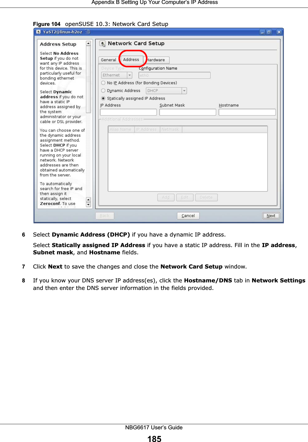
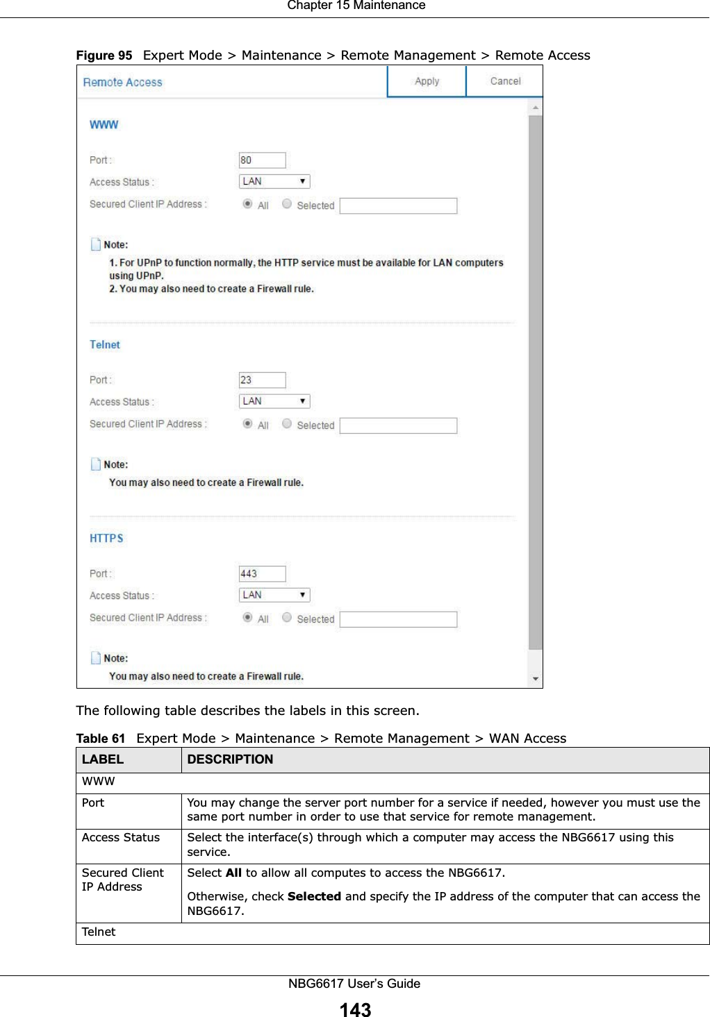
![Appendix B Setting Up Your Computer’s IP AddressNBG6617 User’s Guide1656Select Obtain an IP address automatically if your network administrator or ISP assigns your IP address dynamically.Select Use the following IP Address and fill in the IP address, Subnet mask, and Default gateway fields if you have a static IP address that was assigned to you by your network administrator or ISP. You may also have to enter a Preferred DNS server and an Alternate DNS server, if that information was provided.7Click OK to close the Internet Protocol (TCP/IP) Properties window.8Click OK to close the Local Area Connection Properties window.Verifying Settings1Click Start > All Programs > Accessories > Command Prompt.2In the Command Prompt window, type "ipconfig" and then press [ENTER]. You can also go to Start > Control Panel > Network Connections, right-click a network connection, click Status and then click the Support tab to view your IP address and connection information.Windows VistaThis section shows screens from Windows Vista Professional.1Click Start > Control Panel.2In the Control Panel, click the Network and Internet icon.](https://usermanual.wiki/ZyXEL-Communications/NBG6617.User-Manual-Part-2-99-105-pdf/User-Guide-3078003-Page-67.png)
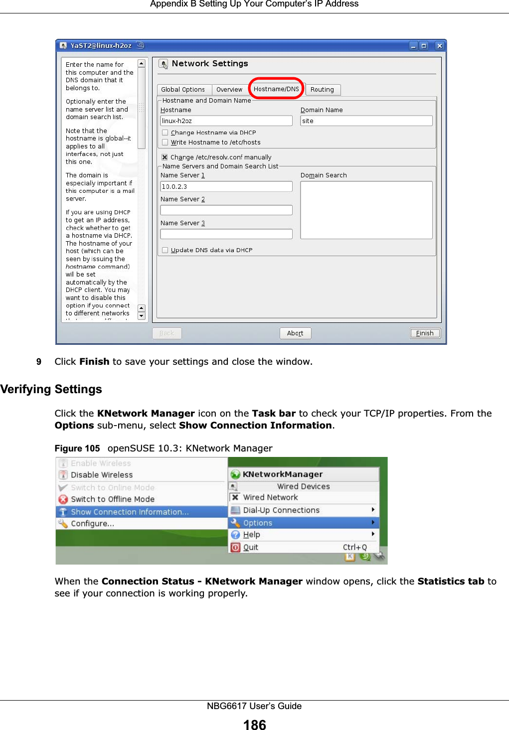
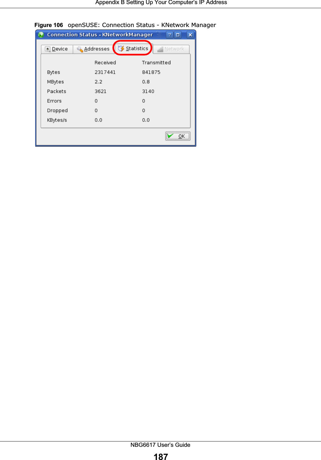
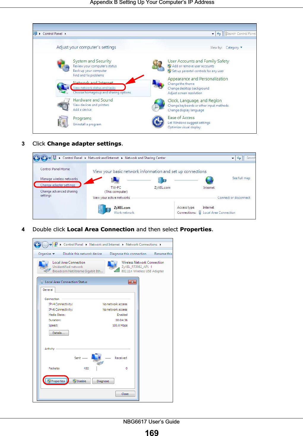
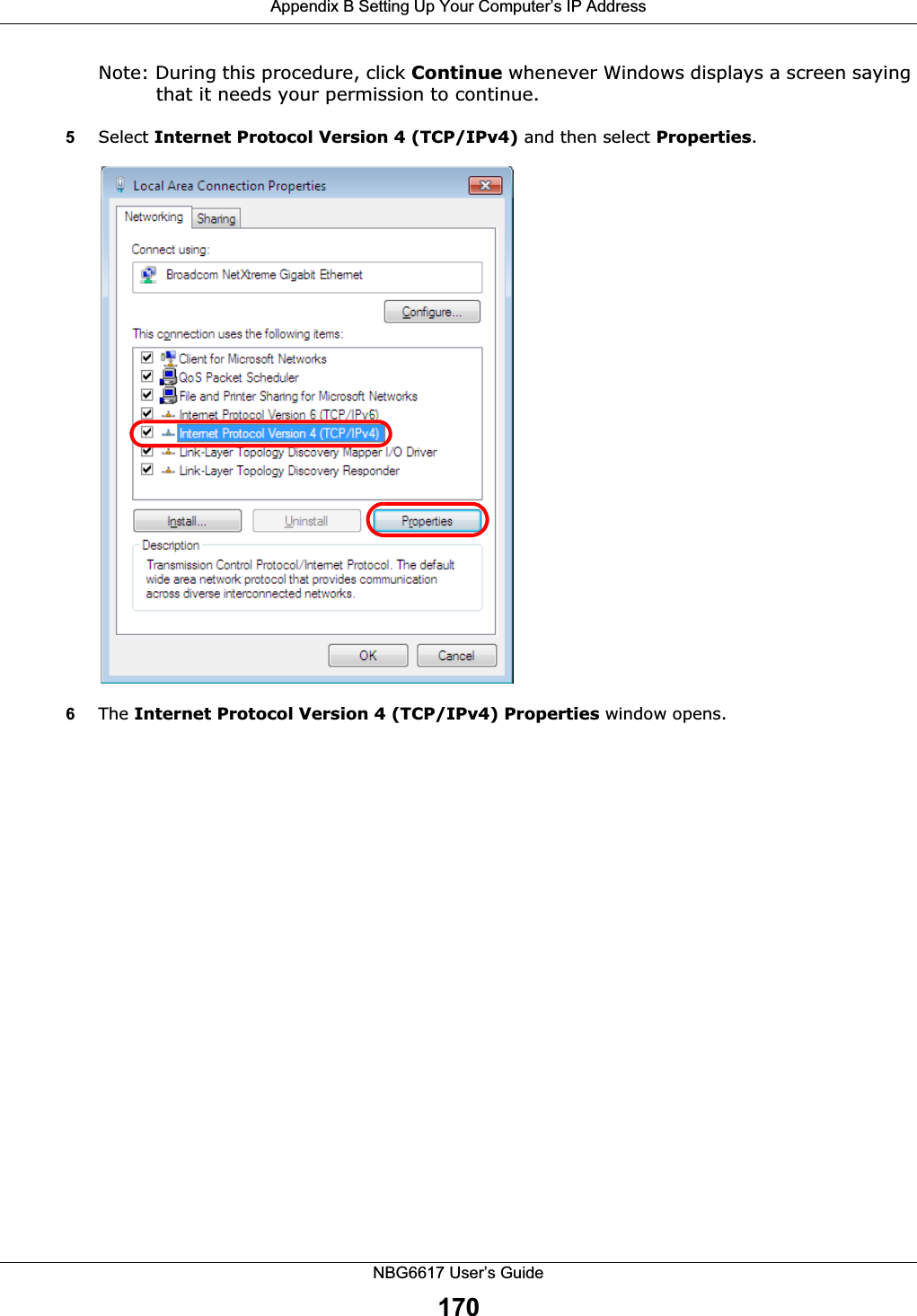
![Appendix B Setting Up Your Computer’s IP AddressNBG6617 User’s Guide1688Select Obtain an IP address automatically if your network administrator or ISP assigns your IP address dynamically.Select Use the following IP Address and fill in the IP address, Subnet mask, and Default gateway fields if you have a static IP address that was assigned to you by your network administrator or ISP. You may also have to enter a Preferred DNS server and an Alternate DNS server, if that information was provided.Click Advanced.9Click OK to close the Internet Protocol (TCP/IP) Properties window.10 Click OK to close the Local Area Connection Properties window.Verifying Settings1Click Start > All Programs > Accessories > Command Prompt.2In the Command Prompt window, type "ipconfig" and then press [ENTER]. You can also go to Start > Control Panel > Network Connections, right-click a network connection, click Status and then click the Support tab to view your IP address and connection information.Windows 7This section shows screens from Windows 7 Enterprise.1Click Start > Control Panel.2In the Control Panel, click View network status and tasks under the Network and Internet category.](https://usermanual.wiki/ZyXEL-Communications/NBG6617.User-Manual-Part-2-99-105-pdf/User-Guide-3078003-Page-70.png)
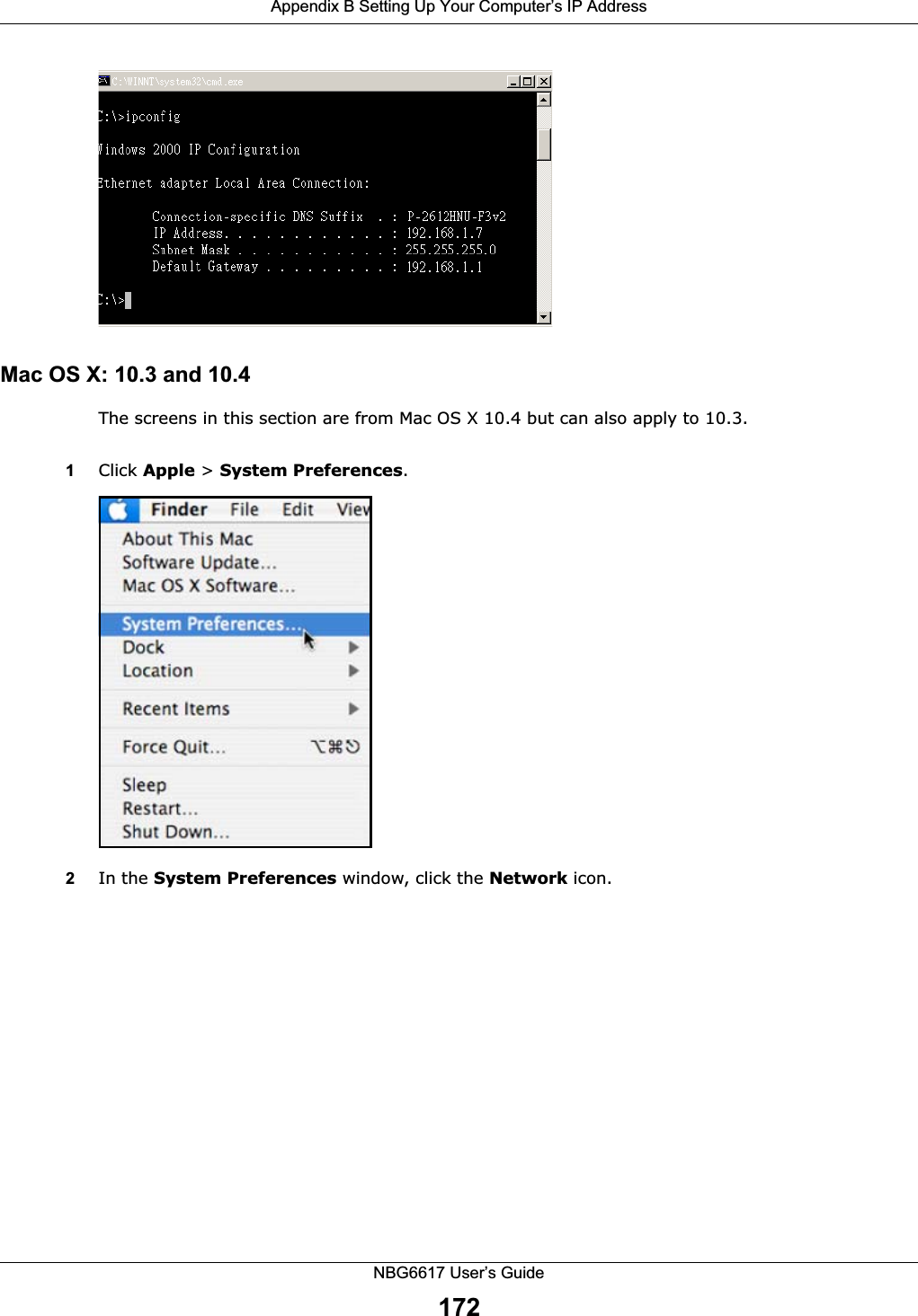
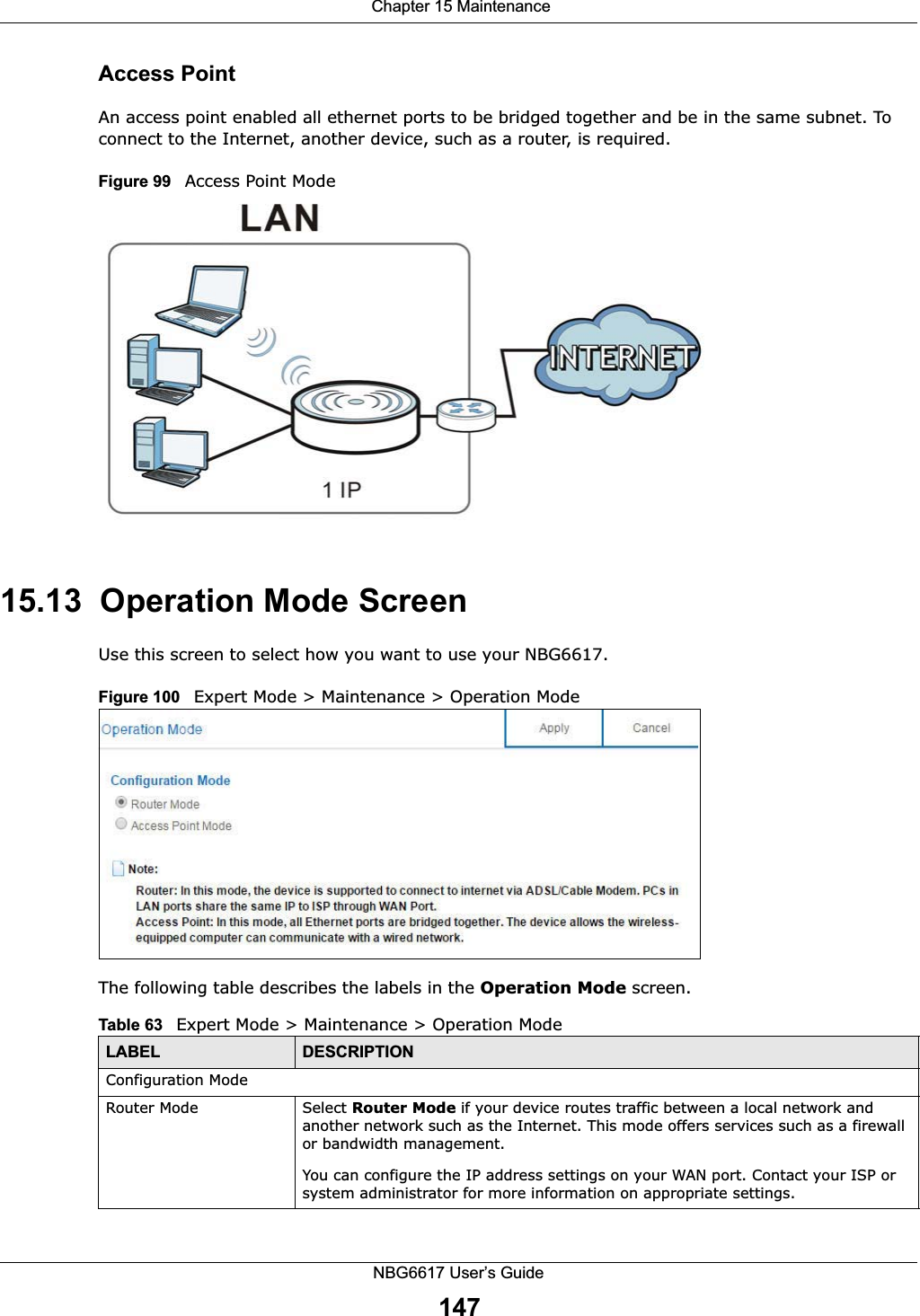
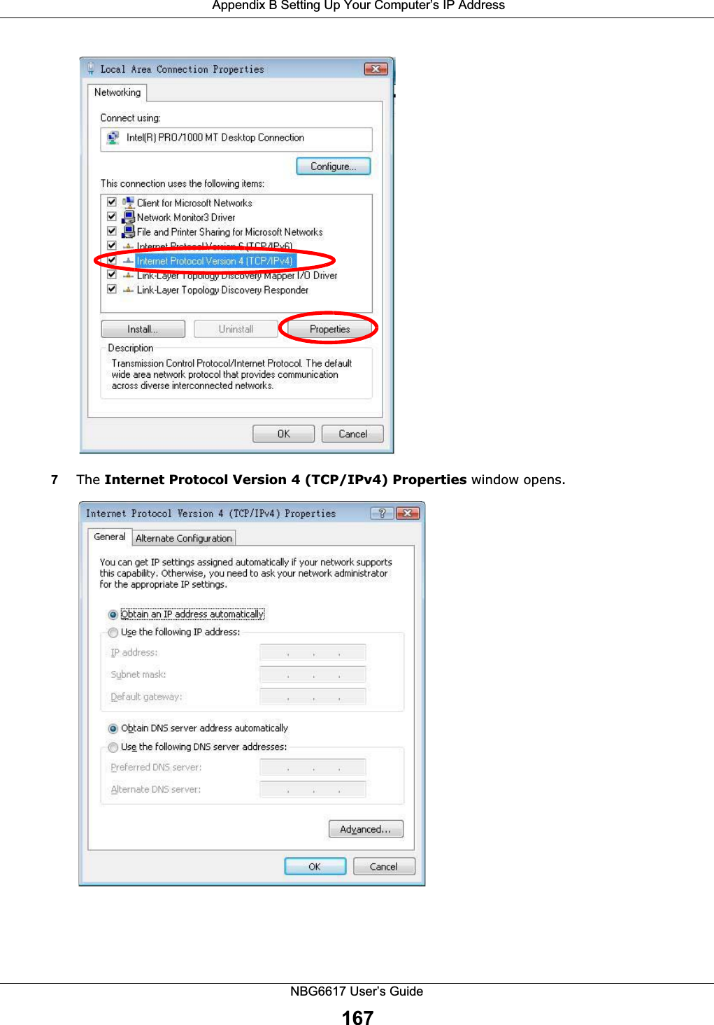
![Appendix B Setting Up Your Computer’s IP AddressNBG6617 User’s Guide1717Select Obtain an IP address automatically if your network administrator or ISP assigns your IP address dynamically.Select Use the following IP Address and fill in the IP address, Subnet mask, and Default gateway fields if you have a static IP address that was assigned to you by your network administrator or ISP. You may also have to enter a Preferred DNS server and an Alternate DNS server, if that information was provided. Click Advanced if you want to configure advanced settings for IP, DNS and WINS. 8Click OK to close the Internet Protocol (TCP/IP) Properties window.9Click OK to close the Local Area Connection Properties window.Verifying Settings1Click Start > All Programs > Accessories > Command Prompt.2In the Command Prompt window, type "ipconfig" and then press [ENTER]. 3The IP settings are displayed as follows.](https://usermanual.wiki/ZyXEL-Communications/NBG6617.User-Manual-Part-2-99-105-pdf/User-Guide-3078003-Page-73.png)