ZyXEL Communications NBG6617 AC1300 MU-MIMO Dual-Band Wireless Gigabit Router User Manual Book
ZyXEL Communications Corporation AC1300 MU-MIMO Dual-Band Wireless Gigabit Router Book
Contents
- 1. User Manual Part 1 (1-98).pdf
- 2. User Manual Part 2 (99-105).pdf
User Manual Part 2 (99-105).pdf
NBG6617 User’s Guide
99
CHAPTER 12
LAN
12.1 Overview
This chapter describes how to configure LAN settings.
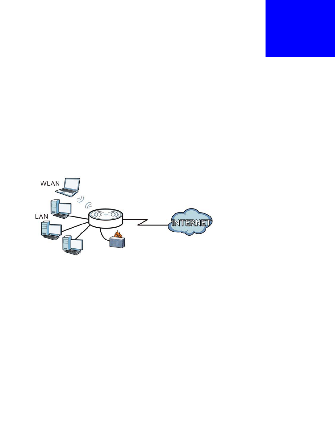
A Local Area Network (LAN) is a shared communication system to which many computers are
attached. A LAN is a computer network limited to the immediate area, usually the same building or
floor of a building.
Figure 61 LAN Example
The LAN screens can help you configure a manage IP address, and partition your physical network
into logical networks.
12.2 What You Can Do
•Use the LAN IP screen to configure the IPv4 and IPv6 addresses for your NBG6617 on the LAN
(Section 12.4 on page 100).
•Use the Static DHCP screen to assign IP addresses on the LAN to specific individual computers
based on their MAC Addresses (Section 12.5 on page 101).
•Use the IPv6 LAN screen to configure the IPv6 address for your NBG6617 on the LAN (Section
12.6 on page 102).
12.3 What You Need To Know
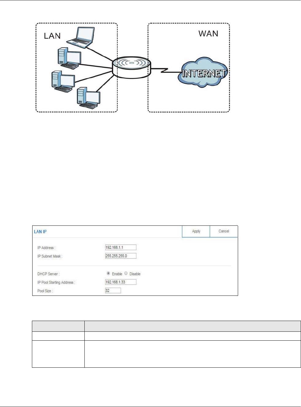
The actual physical connection determines whether the NBG6617 ports are LAN or WAN ports.
There are two separate IP networks, one inside the LAN network and the other outside the WAN
network as shown next.
Chapter 12 LAN
NBG6617 User’s Guide
100
Figure 62 LAN and WAN IP Addresses
The LAN parameters of the NBG6617 are preset in the factory with the following values:
• IPv4 address of 192.168.1.1 with subnet mask of 255.255.255.0 (24 bits)
• DHCP server enabled with 32 client IPv4 addresses starting from 192.168.1.33.
These parameters should work for the majority of installations.
12.4 LAN IP Screen
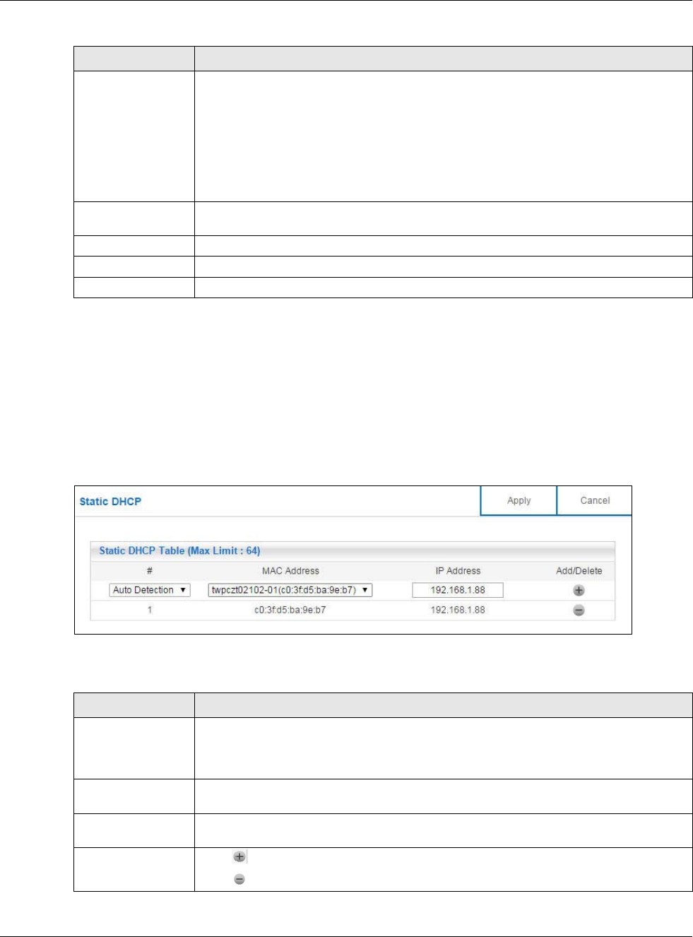
Use this screen to change the IP address for your NBG6617. Click Expert Mode > LAN > LAN IP.
Figure 63 Expert Mode > LAN > LAN IP
The following table describes the labels in this screen.
Table 37 Expert Mode > LAN > LAN IP
LABEL DESCRIPTION
IP Address Type the IP address of your NBG6617 in dotted decimal notation.
IP Subnet Mask The subnet mask specifies the network number portion of an IP address. Your NBG6617
will automatically calculate the subnet mask based on the IP address that you assign.
Unless you are implementing subnetting, use the subnet mask computed by the
NBG6617.
Chapter 12 LAN
NBG6617 User’s Guide
101
12.5 Static DHCP Screen
This screen allows you to assign IP addresses on the LAN to specific individual computers based on
their MAC addresses.
To change your NBG6617’s static DHCP settings, click Expert Mode > LAN > Static DHCP.
Figure 64 Expert Mode > LAN > Static DHCP
The following table describes the labels on this screen.
DHCP Server Select Enable to activate DHCP for LAN.
DHCP (Dynamic Host Configuration Protocol, RFC 2131 and RFC 2132) allows
individual clients (computers) to obtain TCP/IP configuration at startup from a server.
Enable the DHCP server unless your ISP instructs you to do otherwise. Select Disable
to stop the NBG6617 acting as a DHCP server. When configured as a server, the
NBG6617 provides TCP/IP configuration for the clients. If not, DHCP service is
disabled and you must have another DHCP server on your LAN, or else the computers
must be manually configured. When set as a server, fill in the following four fields.
IP Pool Starting
Address
This field specifies the first of the contiguous addresses in the IP address pool for LAN.
Pool Size This field specifies the size, or count of the IP address pool for LAN.
Apply Click Apply to save your changes back to the NBG6617.
Cancel Click Cancel to begin configuring this screen afresh.
Table 37 Expert Mode > LAN > LAN IP (continued)
LABEL DESCRIPTION
Table 38 Expert Mode > LAN > Static DHCP
LABEL DESCRIPTION
#This is the index number of the static IP table entry (row). Select Auto Detection to
automatically detect the MAC address of a computer on your LAN. Otherwise, select
User define to enter the MAC address of a computer on your LAN in the MAC Address
field.
MAC Address This field displays the MAC address of a computer on your LAN. If you select User
define in the # field, enter the MAC address(es) manually.
IP Address This field displays the LAN IP address of a computer on your LAN. If you select User
define in the # field, enter the IP address(es) manually.
Add/Delete Click to add the rule in the MAC filter summary table.
Click to remove a rule.
Chapter 12 LAN
NBG6617 User’s Guide
102
12.6 IPv6 LAN Screen
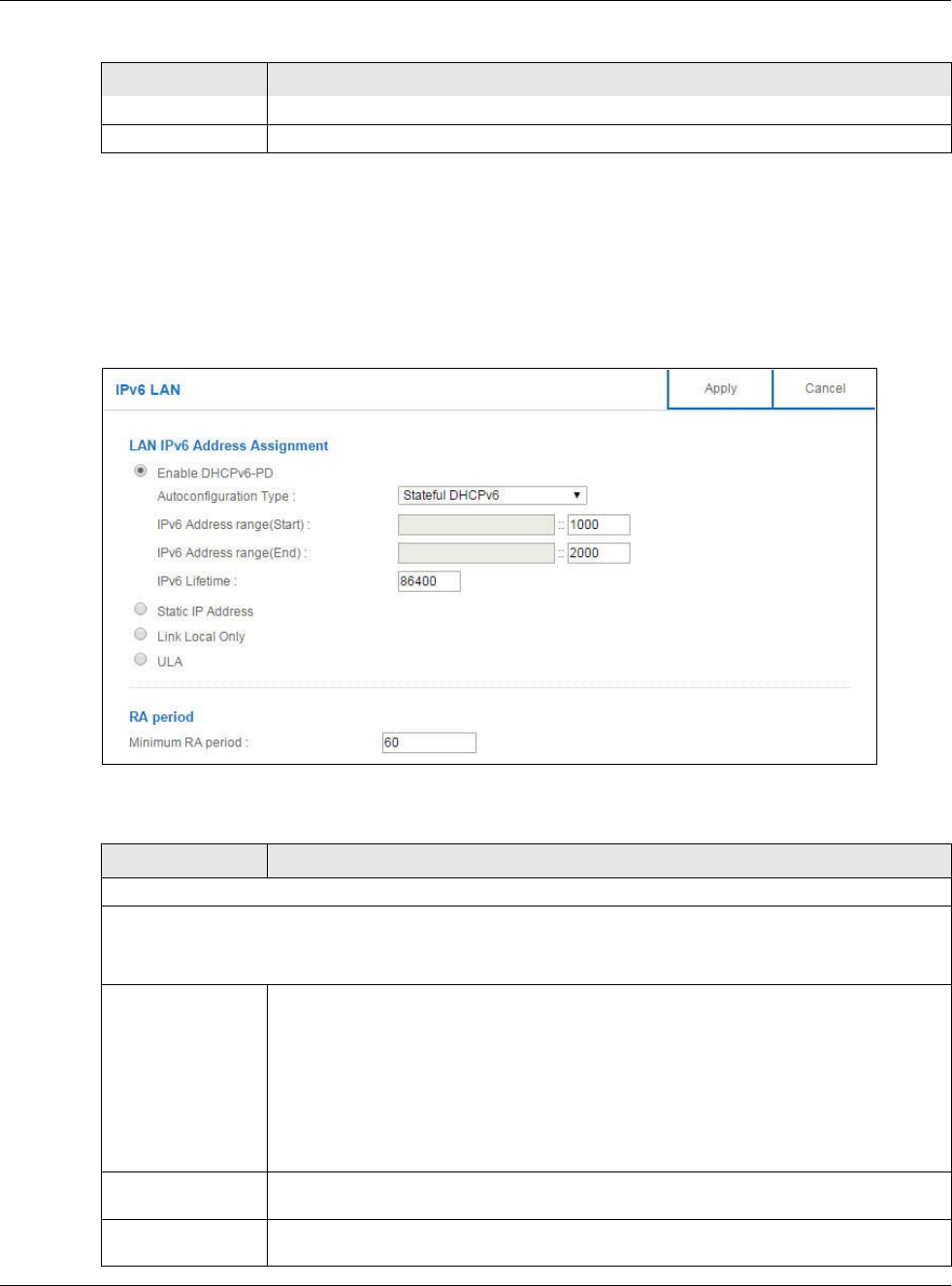
Use this screen to configure the IP address for your NBG6617 on the LAN. Click Expert Mode >
LAN > IPv6 LAN.
Figure 65 Expert Mode > LAN > IPv6 LAN
The following table describes the labels in this screen.
Apply Click Apply to save your changes with the NBG6617.
Cancel Click Cancel to begin configuring this screen afresh.
Table 38 Expert Mode > LAN > Static DHCP (continued)
LABEL DESCRIPTION
Table 39 Expert Mode > LAN > IPv6 LAN
LABEL DESCRIPTION
LAN IPv6 Address Assignment
Enable_DHCPv6-PD
Select this option to use DHCPv6 prefix delegation. The NBG6617 will obtain an IPv6 prefix from the ISP or a
connected uplink router for the LAN.
Autoconfiguration
Type
Select SLAAC + RDNSS to enable IPv6 stateless auto-configuration on this interface.
The interface will generate an IPv6 IP address itself from a prefix obtained from an IPv6
router in the network.
Select SLAAC + Stateless DHCPv6 to enable IPv6 stateless auto-configuration on this
interface. The interface will get an IPv6 address from an IPv6 router and the DHCP
server. The IP address information gets through DHCPv6.
Select Stateful DHCPv6 to allow a DHCP server to assign and pass IPv6 network
addresses, prefixes and other configuration information to DHCP clients.
IPv6 Address range
(Start)
Enter the beginning of the range of IP addresses that this address object represents.
IPv6 Address range
(End)
Enter the end of the range of IP address that this address object represents.
Chapter 12 LAN
NBG6617 User’s Guide
103
IPv6 Lifetime Enter the IPv6 lifetime in the LAN.
Static IP Address
Select this option to manually enter an IPv6 address if you want to use a static IP address.
LAN IPv6 Address Enter the LAN IPv6 address you want to assign to your NBG6617 in hexadecimal
notation.
LAN IPv6 Prefix
Length (48~64)
Enter the 48 to 64 address prefix length to specify in an IPv6 address compose the
network address.
Prefix Preferred
Lifetime
Enter the preferred lifetime for the prefix.
Prefix Valid Lifetime Enter the valid lifetime for the prefix.
Link Local Only
Select this option to only use the link local address on the NBG6617 interfaces in the LAN.
ULA
Select this option to identify a unique local address of the NBG6617 in the LAN.
RA period
Minimum RA period Enter the minimum time in seconds between router advertisement messages.
Apply Click Apply to save your changes back to the NBG6617.
Cancel Click Cancel to begin configuring this screen afresh.
Table 39 Expert Mode > LAN > IPv6 LAN (continued)
LABEL DESCRIPTION

NBG6617 User’s Guide
104
CHAPTER 13
Applications
13.1 Overview
This chapter shows you how to configure parental control, bandwidth management, USB media
sharing, UPnP and file sharing.
13.1.1 What You Can Do
•Use the Parental Control screens to enable parental control, configure the parental control
rules and schedules, and send e-mail notifications. (Section 13.2 on page 106).
•Use the Bandwidth Management screen to configure bandwidth management and the device
priority (Section 13.3 on page 112).
•Use the USB Media Sharing screen to use the NBG6617 as a media server and allow DLNA-
compliant devices to play media files stored in the attached USB device (Section 13.4 on page
117).
•Use the UPnP screen to enable UPnP on your NBG6617 (Section 13.5 on page 118).
•Use the File Sharing screen to allow file sharing via the NBG6617 using Windows Explorer, the
workgroup name or FTP (Section 13.6 on page 119).
•Use the One Connect screen to enable or disable Wi-Fi auto-configuration (Section 13.7 on page
126).
13.1.2 What You Need To Know
The following terms and concepts may help as you read through this chapter.
Keyword Blocking URL Checking
The NBG6617 checks the URL’s domain name (or IP address) and file path separately when
performing keyword blocking.
The URL’s domain name or IP address is the characters that come before the first slash in the URL.
For example, with the URL www.zyxel.com.tw/news/pressroom.php, the domain name is
www.zyxel.com.tw.
The file path is the characters that come after the first slash in the URL. For example, with the URL
www.zyxel.com.tw/news/pressroom.php, the file path is news/pressroom.php.
Since the NBG6617 checks the URL’s domain name (or IP address) and file path separately, it will
not find items that go across the two. For example, with the URL www.zyxel.com.tw/news/
pressroom.php, the NBG6617 would find “tw” in the domain name (www.zyxel.com.tw). It would
also find “news” in the file path (news/pressroom.php) but it would not find “tw/news”.

Chapter 13 Applications
NBG6617 User’s Guide
105
DLNA
The Digital Living Network Alliance (DLNA) is a group of personal computer and electronics
companies that works to make products compatible in a home network. DLNA clients play files
stored on DLNA servers. The NBG6617 can function as a DLNA-compliant media server and stream
files to DLNA-compliant media clients without any configuration.
Workgroup name
This is the name given to a set of computers that are connected on a network and share resources
such as a printer or files. Windows automatically assigns the workgroup name when you set up a
network.
File Systems
A file system is a way of storing and organizing files on your hard drive and storage device. Often
different operating systems such as Windows or Linux have different file systems. The file-sharing
feature on your NBG6617 supports New Technology File System (NTFS), File Allocation Table (FAT)
and FAT32 file systems.
Windows/CIFS
Common Internet File System (CIFS) is a standard protocol supported by most operating systems
in order to share files across the network.
CIFS runs over TCP/IP but uses the SMB (Server Message Block) protocol found in Microsoft
Windows for file and printer access; therefore, CIFS will allow all applications, not just Web
browsers, to open and share files across the Internet.
The NBG6617 uses Common Internet File System (CIFS) protocol for its file sharing functions. CIFS
compatible computers can access the USB file storage devices connected to the NBG6617. CIFS
protocol is supported on Microsoft Windows, Linux Samba and other operating systems (refer to
your systems specifications for CIFS compatibility).
Samba
SMB is a client-server protocol used by Microsoft Windows systems for sharing files, printers, and
so on.
Samba is a free SMB server that runs on most Unix and Unix-like systems. It provides an
implementation of an SMB client and server for use with non-Microsoft operating systems.
File Transfer Protocol
This is a method of transferring data from one computer to another over a network such as the
Internet.
Chapter 13 Applications
NBG6617 User’s Guide
106
Universal Plug-and-Play (UPnP)
UPnP hardware is identified as an icon in the Network Connections folder (Windows XP). Each UPnP
compatible device installed on your network will appear as a separate icon. Selecting the icon of a
UPnP device will allow you to access the information and properties of that device.
13.1.3 Before You Begin
Make sure the NBG6617 is connected to your network and turned on.
1Connect the USB device to one of the NBG6617’s USB ports.
2The NBG6617 detects the USB device and makes its contents available for browsing. If you are
connecting a USB hard drive that comes with an external power supply, make sure it is connected
to an appropriate power source that is on.
Note: If your USB device cannot be detected by the NBG6617, see the troubleshooting
for suggestions.
13.2 Parental Control
Parental Control allows you to block specific URLs. You can also define time periods and days during
which the NBG6617 performs parental control on a specific user.
13.2.1 General Screen
Use this screen to enable parental control, view the parental control rules and schedules.
In Expert mode, click Applications > Parental Control > General to open the following screen.
Figure 66 Expert Mode > Applications > Parental Control > General

Chapter 13 Applications
NBG6617 User’s Guide
107
The following table describes the fields in this screen.
13.2.1.1 Add/Edit a Parental Control Rule
Click Add new rules in the Parental Control screen to add a new rule or click the Edit icon next
to an existing rule to edit it. Use this screen to configure a restricted access schedule and/or URL
filtering settings to block the users on your network from accessing certain web sites.
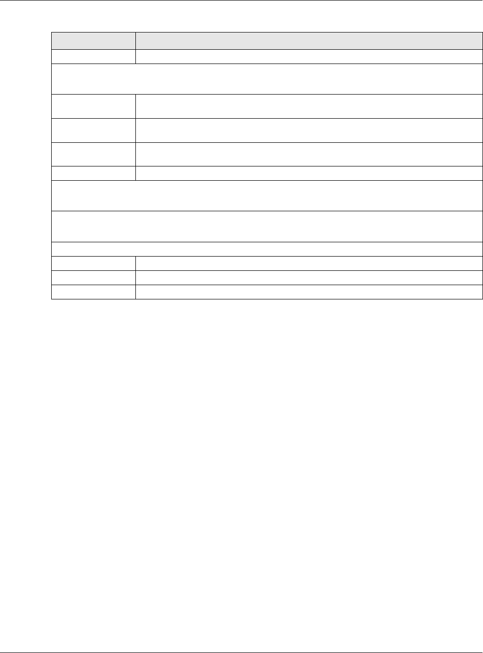
Table 40 Expert Mode > Applications > Parental Control > General
LABEL DESCRIPTION
General
Parental
Control
Select Enable to activate parental control. Otherwise, select Disable to turn it off.
Add new rules Click this if you want to configure a new parental control rule.
Parental Control Rules
#This shows the index number of the rule.
Status This indicates whether the rule is active or not.
A yellow bulb signifies that this rule is active. A gray bulb signifies that this rule is not active.
User Name This shows the name of the user to which this rule applies.
Schedule This shows whether the user is able to access the Internet through the NBG6617 (Allow) or
not (Block) at the moment.
Modify Click the Edit icon to go to the screen where you can edit the rule.
Click the Delete icon to delete an existing rule.
Bonus If the user is currently not permitted to access the Internet, you can click the Bonus to
allow access for a specified period of time. A screen then displays allowing you to set how
long (in minutes) the user is allowed to access the Internet.
This button is grayed out if the user is now able to access the Internet.
Remaining
Time
This field displays the amount of Internet access time that remains for each user before the
NBG6617 blocks the user from accessing the Internet.
None means there is no extra Internet access time.
Apply Click Apply to save your changes.
Cancel Click Cancel to restore your previously saved settings.
Chapter 13 Applications
NBG6617 User’s Guide
108
Figure 67 Expert Mode > Applications > Parental Control > General: Add/Edit new rules
The following table describes the fields in this screen.
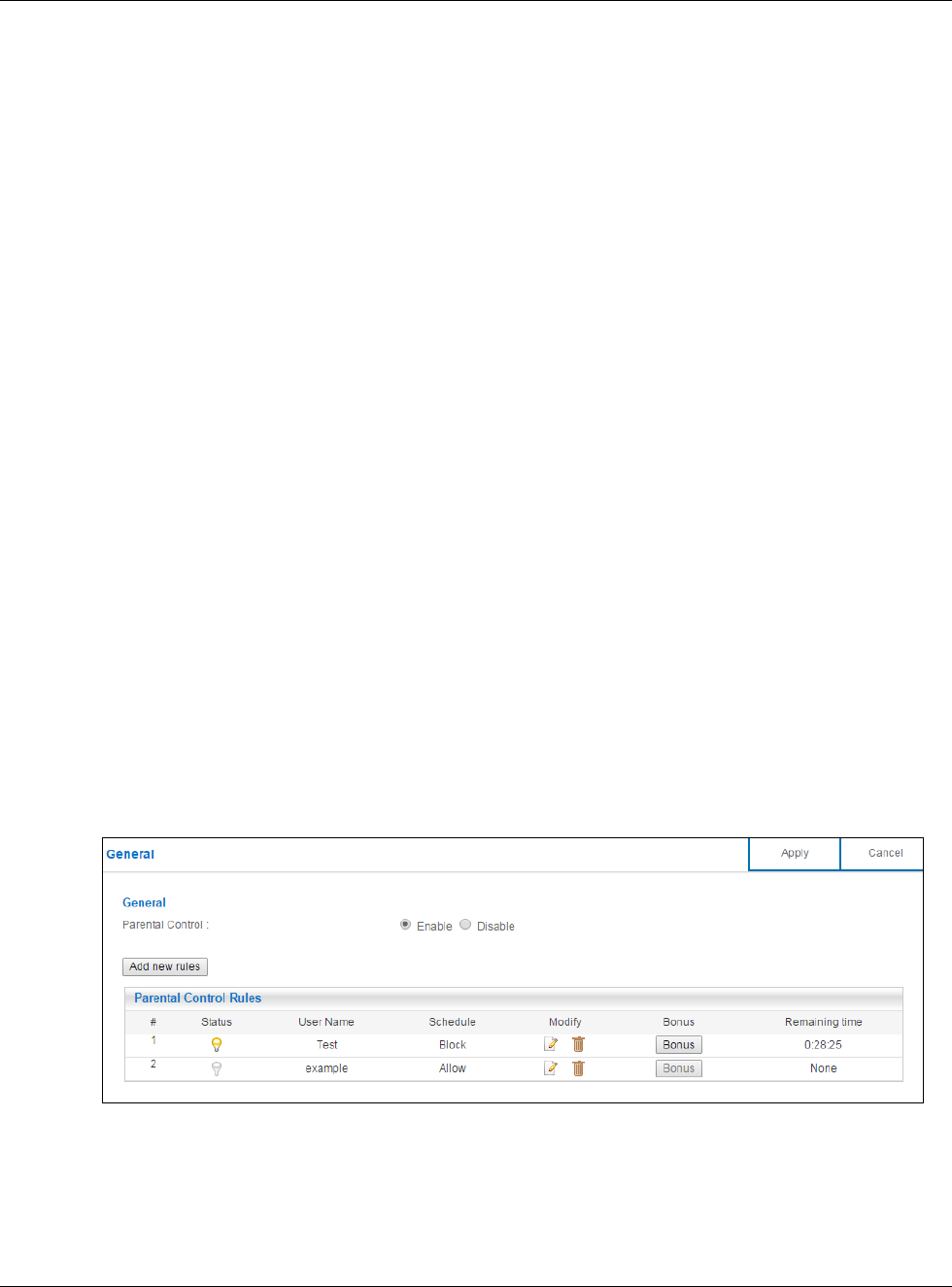
Table 41 Expert Mode > Applications > Parental Control > General: Add/Edit new rules
LABEL DESCRIPTION
General
Active Select the checkbox to activate this parental control rule.
User Name Enter a descriptive name for the user.
Device List The left text box lists the system name of the LAN user device which is connected to the
NBG6617 and assigned an IP address.
From the left text box, select the LAN user device to which you want to apply this rule and
click Add to move it to the right text box.
To remove a user device, select it from the right text box and click Delete.
Internet Access
Schedule
The y-axis shows the days that you want the NBG6617 to perform parental control and
allow the user to access the Internet.
The x-axis shows the time period during which the LAN user is allowed access.
A blue block signifies that this rule is active. A gray block signifies that this rule is not active.
Clean All Click Clean All to remove blocks you selected.
Select All Click Select All to choose all blocks.
Chapter 13 Applications
NBG6617 User’s Guide
109
13.2.1.2 Add/Edit a Service
Click Add new service in the Parental Control > Add new rules screen to add a new entry or
click the Edit icon next to an existing entry to edit it. Use this screen to configure a service rule.
Figure 68 Expert Mode > Applications > Parental Control > General: Add/Edit new rules: Add new
service
The following table describes the fields in this screen.
Network Service
Network
Service Setting
If you select Block, the NBG6617 prohibits the users from using the services listed below.
If you select Allow, the NBG6617 blocks all services except ones listed below.
Add new
service
Click this to show a screen in which you can add a new service rule. You can configure the
Service Name, Protocol, and Port of the new rule.
#This shows the index number of the rule. Select the checkbox next to the rule to activate it.
Service Name This shows the name of the service.
Protocol:Port This shows the protocol and the port of the service.
Modify Click the Edit icon to go to the screen where you can edit the rule.
Click the Delete icon to delete an existing rule.
Block Site/URL Keyword
Keyword Enter a keyword and click Add to add it to the keyword list. This has the NBG6617 block
access to the website URLs that contain the keyword.
Keyword List Select a keyword and click Delete to remove it.
Click Clear All to remove all keywords from the keyword list.
Apply Click Apply to save your settings back to the NBG6617.
Back Click Back to return to the previous screen.
Table 41 Expert Mode > Applications > Parental Control > General: Add/Edit new rules (continued)
LABEL DESCRIPTION
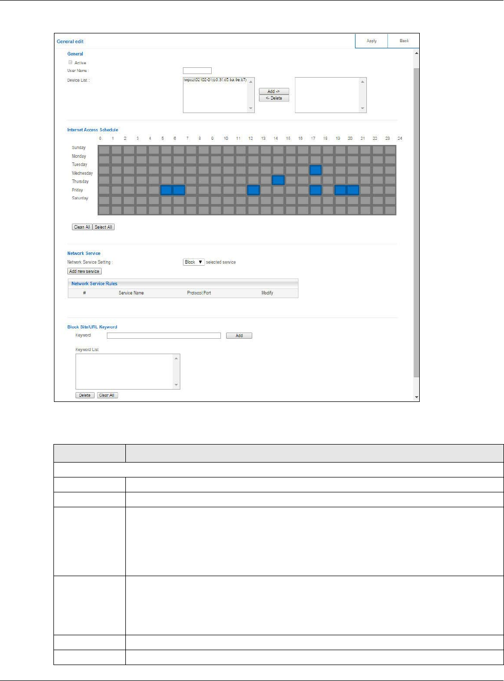
Table 42 Expert Mode > Applications > Parental Control > General: Add/Edit new rules: Add new
service
LABEL DESCRIPTION
Service Name Select the name of the service. Otherwise, select UserDefined and manually specify the
protocol and the port of the service.
If you have chosen a pre-defined service in the Service Name field, this field will not be
configurable.
Protocol Select the transport layer protocol used for the service. Choices are TCP, UDP, or TCP/
UDP.
Chapter 13 Applications
NBG6617 User’s Guide
110
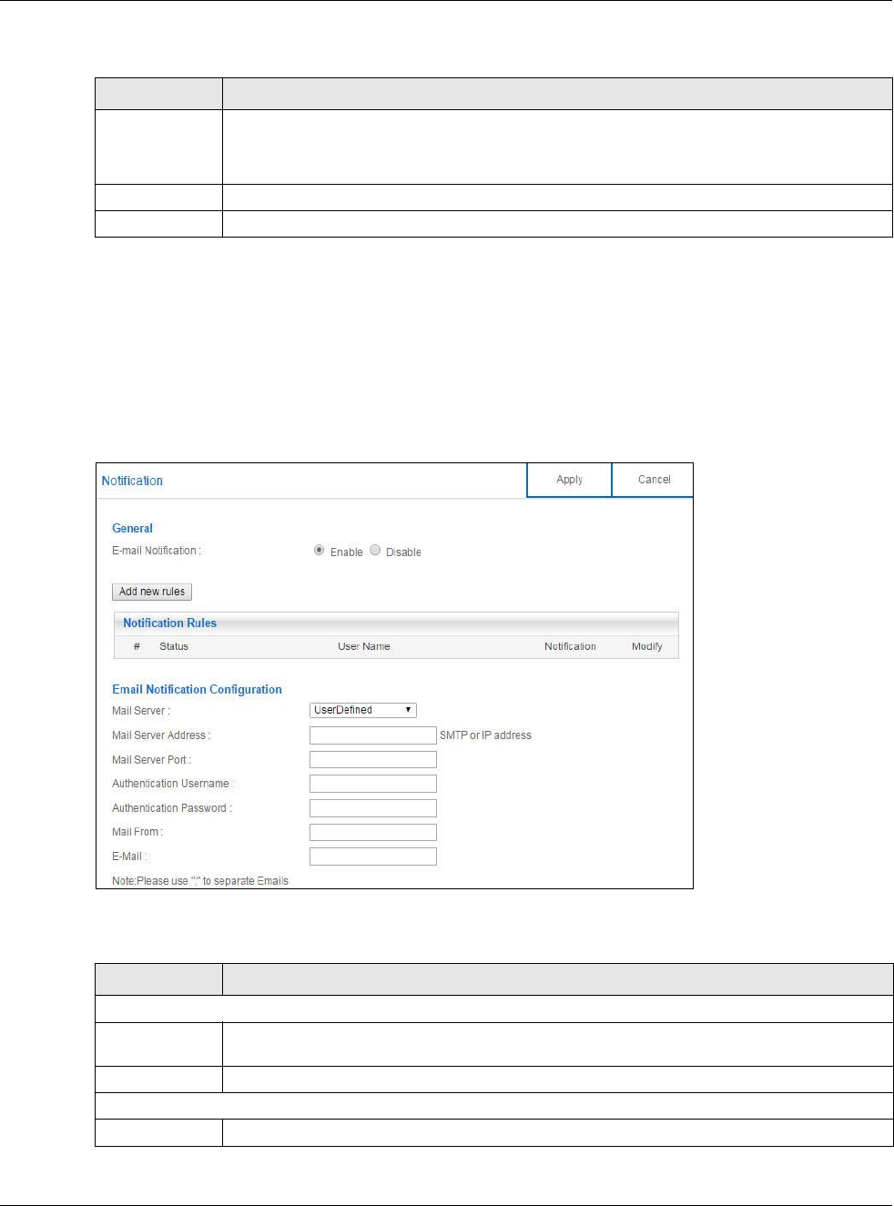
13.2.2 Notification Screen
Use this screen to have the NBG6617 send e-mail notifications when the user(s) is connected to the
NBG6617 for Internet access during the specified time periods.
In Expert mode, click Applications > Parental Control > Notification to open the following
screen.
Figure 69 Expert Mode > Applications > Parental Control > Notification
The following table describes the fields in this screen.
Port Enter the port of the service.
If you have chosen a pre-defined service in the Service Name field, this field will not be
configurable.
Apply Click Apply to save your settings with the NBG6617.
Back Click Back to return to the previous screen.
Table 42 Expert Mode > Applications > Parental Control > General: Add/Edit new rules: Add new
service (continued)
LABEL DESCRIPTION
Table 43 Expert Mode > Applications > Parental Control > Notification
LABEL DESCRIPTION
General
E-mail
Notification
Select Enable to activate e-mail notifications.
Add new rules Click this if you want to configure a new parental monitor rule.
Notification Rules
#This shows the index number of the rule.
Chapter 13 Applications
NBG6617 User’s Guide
111
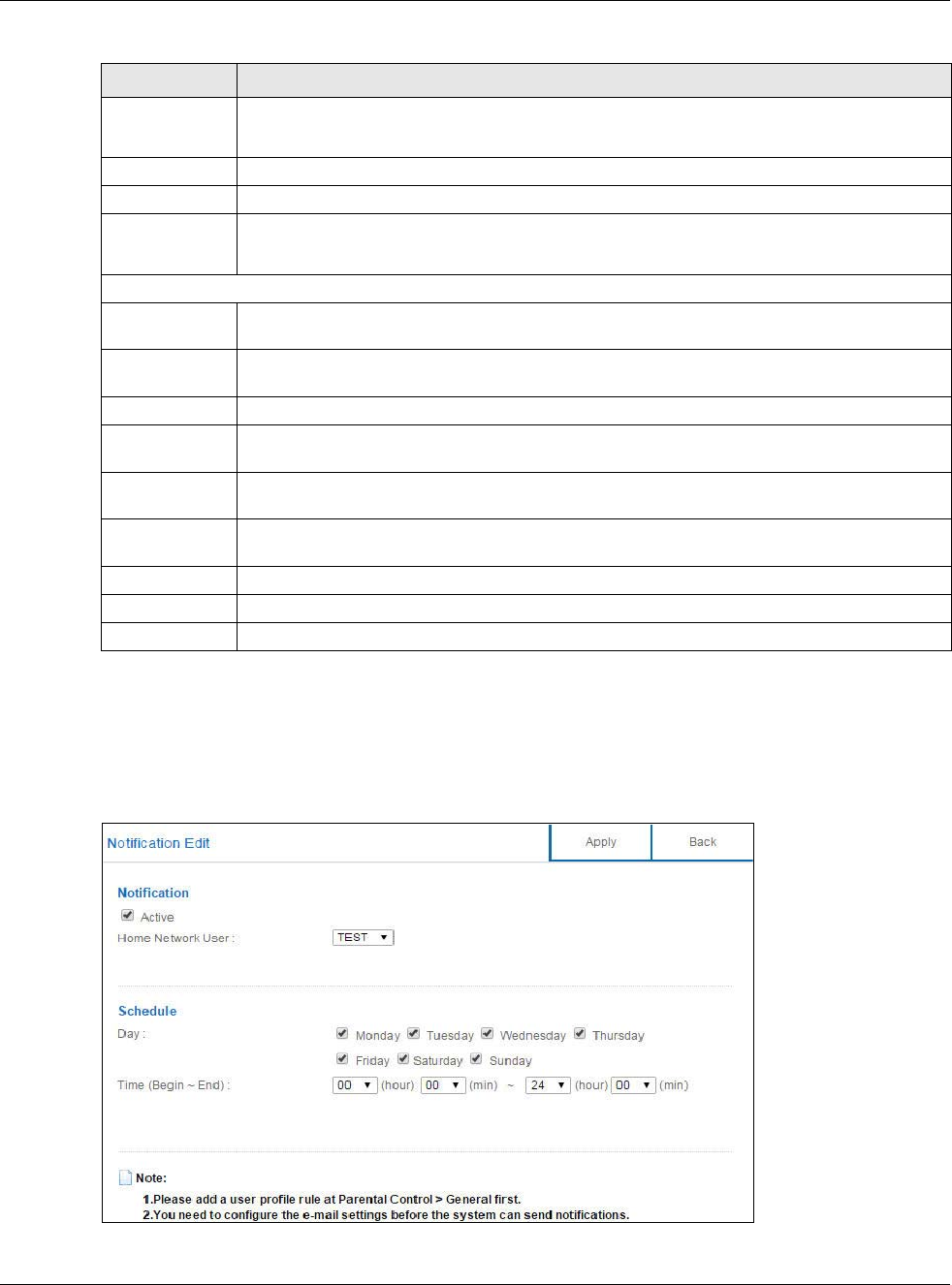
13.2.2.1 Add/Edit a Notification Rule
Click Add new rules in the Notification screen to add a new rule or click the Edit icon next to an
existing rule to edit it. Use this screen to set a schedule and have the NBG6617 send a notification
when the specified user connects to the NBG6617 at the scheduled time.
Figure 70 Expert Mode > Applications > Notification: Add/Edit new rules
Status This indicates whether the rule is active or not.
A yellow bulb signifies that this rule is active. A gray bulb signifies that this rule is not active.
User Name This shows the name of the user to which this rule applies.
Notification This shows the e-mail address to which the notification is sent.
Modify Click the Edit icon to go to the screen where you can edit the rule.
Click the Delete icon to delete an existing rule.
Email Notification Configuration
Mail Server Select the mail server. Otherwise, select UserDefined and manually specify the mail server
address and the port of the mail server.
Mail Server
Address
Type the name or IP address of the outgoing SMTP server.
Mail Server Port Enter the same port number here as is on the mail server for mail traffic.
Authentication
Username
Type the user name to provide to the SMTP server for authentication when the notification is
e-mailed.
Authentication
Password
Type the password to provide to the SMTP server for authentication when the notification is
e-mailed.
Mail From Type the e-mail address from which the outgoing e-mail is delivered. This address is used in
replies.
E-Mail Type the e-mail address (or addresses) to which the outgoing e-mail is delivered.
Apply Click Apply to save your changes.
Cancel Click Cancel to restore your previously saved settings.
Table 43 Expert Mode > Applications > Parental Control > Notification (continued)
LABEL DESCRIPTION
Chapter 13 Applications
NBG6617 User’s Guide
112
The following table describes the fields in this screen.
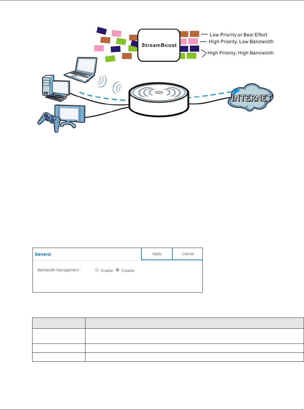
13.3 Bandwidth Management
The NBG6617 supports the new StreamBoost technology, introduced by Qualcomm, to redistribute
traffic over the NBG6617 for the best possible performance in a home network.
Streamboost is smart Quality of Service (QoS). Streamboost detects traffic flow and applies traffic
shaping policies automatically. It gives each device and each application priority and provides the
exact amount of bandwidth they need at a given time. This helps free up bandwidth for other
applications or connected devices. If there is not enough bandwidth for optimal performance,
Streamboost makes sure the application or device has the minimum acceptable bandwidth which is
determined according to StreamBoost’s cloud-based database.
Real-time application traffic (such as on-line games or communications) and video/audio streaming
are given the highest priority. Downloads or torrent files are classified as best effort and placed
lower than general network traffic (general browsing).
In the figure below, the StreamBoost-enabled NBG6617 differentiates incoming traffic flow going
from the LAN device (A) or wireless device (B) to the Internet. It shapes traffic and gives priority
and allocates bandwidth according to traffic types.
Table 44 Expert Mode > Applications > Notification: Add/Edit new rules
LABEL DESCRIPTION
Notification
Active Select the checkbox to activate this notification rule.
Home Network
User
Select the user that you want to apply this rule to from the drop-down list box.
Note: You should have configured a parental control rule already for the specified user.
Schedule
Day Select check boxes for the days that you want the NBG6617 to perform notification.
Time (Begin ~
End)
Define the time period during that you want the NBG6617 to perform notification.
Apply Click Apply to save your settings back to the NBG6617.
Back Click Back to return to the previous screen.
Chapter 13 Applications
NBG6617 User’s Guide
113
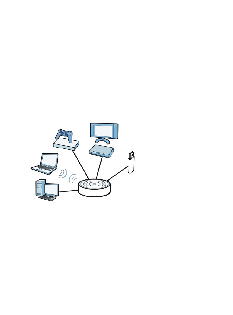
Figure 71 StreamBoost Management Example
The StreamBoost engine on the NBG6617 can identify the types of connected devices (such as PC,
smart phone, tablet, TV or game console) in your network. When there is not enough bandwidth to
support traffic of the same priority, the NBG6617 refers to the connected device priority. Traffic
from the device with the lowest priority is classified as best-effort traffic. Use the Advanced screen
to prioritize the connected devices (Section 13.3.2 on page 113).
13.3.1 General Screen
Use this screen to enable StreamBoost.
In Expert mode, click Applications > Bandwidth Management > General to open the following
screen.
Figure 72 Expert Mode > Applications > Bandwidth Management > General
The following table describes the labels in this screen.
13.3.2 Advanced Screen
Use this screen to configure the maximum allowable bandwidth on the NBG6617 and allow the
NBG6617 to get StreamBoost database updates automatically.
A
B
Table 45 Expert Mode > Applications > Bandwidth Management > General
LABEL DESCRIPTION
Enable
StreamBoost
Select this option to turn on Streamboost management on the NBG6617.
Apply Click Apply to save your customized settings.
Cancel Click Cancel to begin configuring this screen afresh.
Chapter 13 Applications
NBG6617 User’s Guide
114
In Expert mode, click Applications > Bandwidth Management > Advanced to open the
following screen.
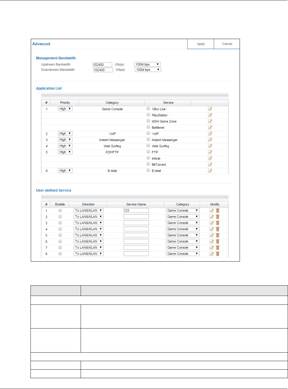
Figure 73 Expert Mode > Applications > Bandwidth Management > Advanced
The following table describes the labels in this screen.
Table 46 Expert Mode > Applications > Bandwidth Management > Advanced
LABEL DESCRIPTION
Management Bandwidth
Upstream
Bandwidth
Select the total amount of bandwidth that you want to dedicate to uplink (or outgoing)
traffic. Otherwise, select User Defined to manually enter the bandwidth.
This is traffic from LAN/WLAN to WAN.
Downstream
Bandwidth
Select the total amount of bandwidth that you want to dedicate to downlink (or
incoming) traffic. Otherwise, select User Defined to manually enter the bandwidth.
This is traffic from WAN to LAN/WLAN.
Application List
#This is the index number of the application on the NBG6617.
Priority Use the drop-down list box to select the priority of the connected device.
Chapter 13 Applications
NBG6617 User’s Guide
115
13.3.2.1 Application List Edit
Click the Edit icon next to an existing rule to edit it. Use this screen to view and configure the
application rules.
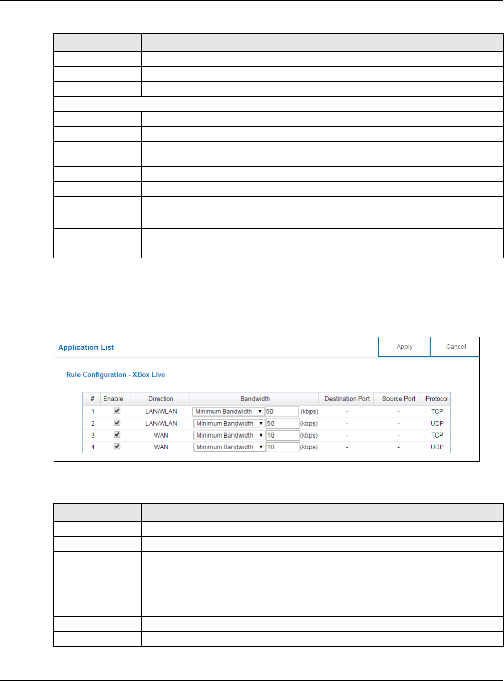
Figure 74 Expert Mode > Applications > Bandwidth Management > Advanced: Application List: Edit
The following table describes the labels in this screen.
Category This column displays the categories to which the connected device applies.
Service This displays the name of the service.
Edit Click the Edit icon to open the edit screen where you can modify an existing rule.
User-defined Service
#This is the index number of the user-defined service.
Enable Select the check box to enable the service. Clear the check box to disable the service.
Direction Use the drop-down list box to select a direction of travel of packets for which you want
to configure services.
Service Name Enter a descriptive name for the service.
Category Use the drop-down list box to select a category of the service.
Modify Click the Edit icon to open the edit screen where you can modify an existing rule.
Click the Delete icon to remove a rule.
Apply Click Apply to save your customized settings.
Cancel Click Cancel to begin configuring this screen afresh.
Table 46 Expert Mode > Applications > Bandwidth Management > Advanced (continued)
LABEL DESCRIPTION
Table 47 Expert Mode > Applications > Bandwidth Management > Advanced: Application List: Edit
LABEL DESCRIPTION
#This is the index number of the service rule.
Enable Select the check box to enable the rule. Clear the check box to disable the rule.
Direction This displays traffic direction of the service.
Bandwidth Select Maximum Bandwidth or Minimum Bandwidth and enter the maximum
bandwidth or minimum bandwidth (in Kbps) next to the drop-down list box allowed for
the traffic.
Destination Port This displays the port number of the destination that define the traffic type.
Source Port This displays the port number of the source that define the traffic type.
Protocol This is the transport layer protocol used for the service.
Chapter 13 Applications
NBG6617 User’s Guide
116
13.3.2.2 User-defined Service Edit
Click the Edit icon in the Modify field to open the edit screen. Use this screen to configure user-
defined service rules.
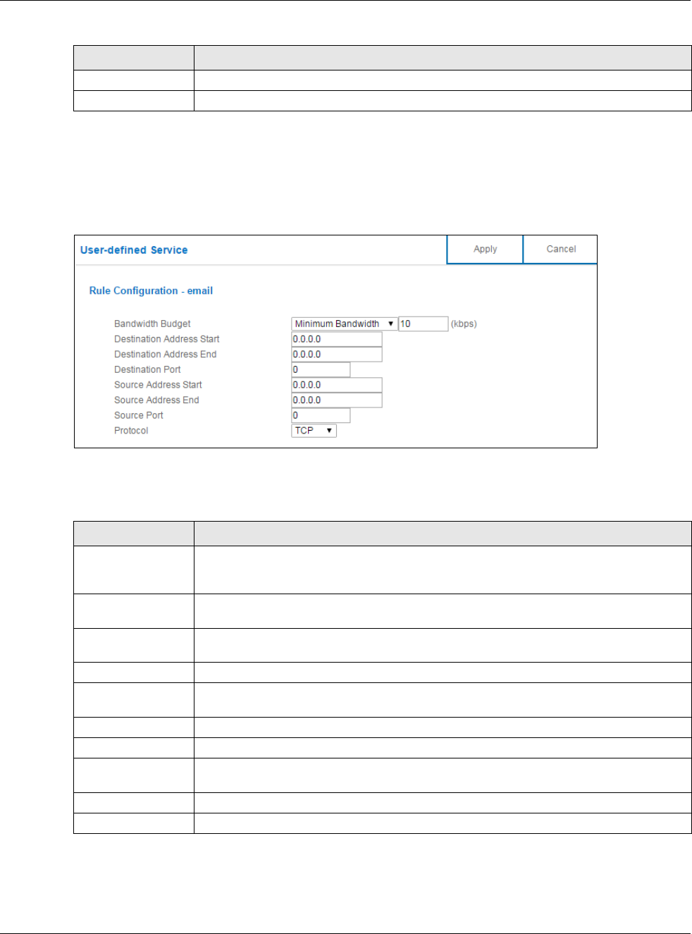
Figure 75 Expert Mode > Applications > Bandwidth Management > Advanced: User-defined
Service: Edit
The following table describes the labels in this screen.
Apply Click Apply to save your customized settings.
Cancel Click Cancel to begin configuring this screen afresh.
Table 47 Expert Mode > Applications > Bandwidth Management > Advanced: Application List: Edit
LABEL DESCRIPTION
Table 48 Expert Mode > Applications > Bandwidth Management > Advanced: User-defined Service:
Edit
LABEL DESCRIPTION
Bandwidth Budget Select Maximum Bandwidth or Minimum Bandwidth and enter the maximum
bandwidth or minimum bandwidth (in Kbps) next to the drop-down list box allowed for
the service.
Destination
Address Start
Enter the single IP address or the starting IP address in a range here.
Destination
Address End
Enter the ending IP address in a range here.
Destination Port This is a single port number that defines your user-defined service.
Source Address
Start
Enter the single IP address or the starting IP address in a range here.
Source Address End Enter the ending IP address in a range here.
Source Port This is a single port number that defines your user-defined service.
Protocol Select the transport layer protocol (TCP, UDP or BOTH) that defines your user-defined
service.
Apply Click Apply to save your customized settings.
Cancel Click Cancel to begin configuring this screen afresh.
Chapter 13 Applications
NBG6617 User’s Guide
117
13.4 USB Media Sharing Screen
You can set up your NBG6617 to act as a media server to provide media (like video) to DLNA-
compliant players, such as Windows Media Player, ZyXEL DMAs (Digital Media Adapters), Xboxes or
PS3s. The media server and clients must have IP addresses in the same subnet.
The NBG6617 media server enables you to:
• Publish all folders for everyone to play media files in the USB storage device connected to the
NBG6617.
• Use hardware-based media clients like the DMA-2500 to play the files.
Note: Anyone on your network can play the media files in the published folders. No user
name and password nor other form of security is required.
The following figure is an overview of the NBG6617’s media server feature. DLNA devices A and B
can access and play files on a USB device (C) which is connected to the NBG6617 (D).
Figure 76 Media Server Overview
Use this screen to have the NBG6617 act as a DLNA-compliant media server that lets DLNA-
compliant media clients on your network play video, music, and photos from the NBG6617 (without
having to copy them to another computer).
In Expert mode, click Applications > USB Media Sharing to open the following screen.
A
B
C
D
Chapter 13 Applications
NBG6617 User’s Guide
118
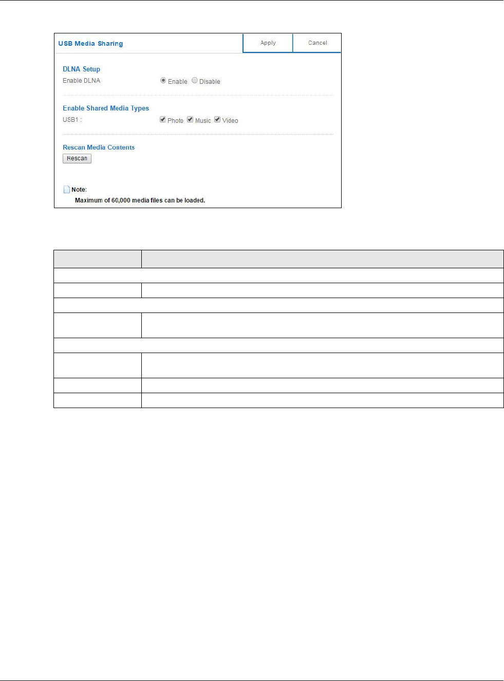
Figure 77 Expert Mode > Applications > USB Media Sharing
The following table describes the labels in this screen.
13.5 UPnP Screen
Universal Plug and Play (UPnP) is a distributed, open networking standard that uses TCP/IP for
simple peer-to-peer network connectivity between devices. A UPnP device can dynamically join a
network, obtain an IP address, convey its capabilities and learn about other devices on the network.
In turn, a device can leave a network smoothly and automatically when it is no longer in use.
Use this screen to enable UPnP on your NBG6617.
In Expert mode, click Applications > UPnP to open the following screen.
Table 49 Expert Mode > Applications > USB Media Sharing
LABEL DESCRIPTION
DLNA Setup
Enable DLNA Select this to have the NBG6617 function as a DLNA-compliant media server.
Enable Shared Media Types
USB1 Select the media type that you want to share on the USB device connected to the
NBG6617’s USB port.
Rescan Media Contents
Rescan Click this button to have the NBG6617 scan the media files on the connected USB device
and do indexing of the file list again so that DLNA clients can find the new files if any.
Apply Click Apply to save your changes back to the NBG6617.
Cancel Click Cancel to begin configuring this screen afresh.
Chapter 13 Applications
NBG6617 User’s Guide
119
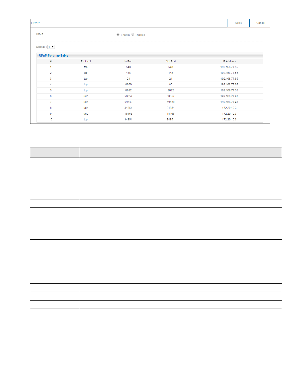
Figure 78 Expert Mode > Applications > UPnP
The following table describes the fields in this screen.
13.6 File Sharing
You can also share files on a USB memory stick or hard drive connected to your NBG6617 with
users on your network.
Table 50 Expert Mode > Applications > UPnP
LABEL DESCRIPTION
UPnP Select Enable to activate UPnP. Be aware that anyone could use a UPnP application to
open the web configurator's login screen without entering the NBG6617's IP address
(although you must still enter the password to access the web configurator).
Display Select the page number from the drop-down list box to display the UPnP port mapping
rules.
UPnP Portmap Table
#This is the number of an individual UPnP entry.
Protocol This is the transport layer protocol used for the service.
In Port In Port is a port that a LAN computer uses when it requests a particular service. This
port is only applicable to the local network.
This field displays the port number of the UPnP entry.
Out Port Out Port is the well-known port that the WAN server uses to reply to the LAN computer
that made the request using In Port.
In the below example, In Port 8000 is paired with Out Port 80. A user on the WAN
could enter http://A.B.C.D:8000 to access the internal computer with private IP address
192.168.77.55 where A.B.C.D is the WAN IP address or URL of the NBG6617.
This field displays the port number of the UPnP entry.
IP Address This field displays the IP address of this UPnP entry.
Apply Click Apply to save the setting to the NBG6617.
Cancel Click Cancel to return to the previously saved settings.
Chapter 13 Applications
NBG6617 User’s Guide
120
The following figure is an overview of the NBG6617’s file-sharing server feature. Computers A and
B can access files on a USB device (C) which is connected to the NBG6617 (D).
Figure 79 File Sharing Overview
Note: The read and write performance may be affected by amount of file-sharing traffic
on your network, type of connected USB device and your USB version (1.1 or 2.0).
13.6.1 SAMBA Server Screen
Use this screen to set up file-sharing via the NBG6617 using Windows Explorer or the workgroup
name. You can also configure the workgroup name and create file-sharing user accounts.
In Expert mode, click Applications > File Sharing > SAMBA to open the following screen.
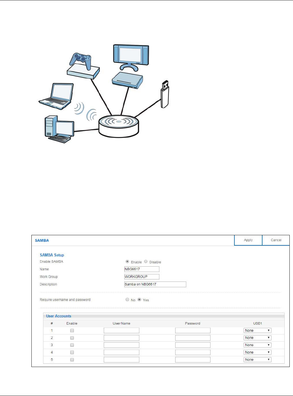
Figure 80 Expert Mode > Applications > File Sharing > SAMBA
A
BC
D

Chapter 13 Applications
NBG6617 User’s Guide
121
The following table describes the labels in this screen.
13.6.2 FTP Server Screen
Use this screen to set up file sharing via the NBG6617 using FTP and create user accounts.
In Expert mode, click Applications > File Sharing > FTP to open the following screen.
Table 51 Expert Mode > Applications > File Sharing > SAMBA
LABEL DESCRIPTION
SAMBA Setup
Enable SAMBA Select this to enable file sharing through the NBG6617 using Windows Explorer or by
browsing to your work group.
Name Specify the name to identify the NBG6617 in a work group.
Work Group You can add the NBG6617 to an existing or a new workgroup on your network. Enter the
name of the workgroup which your NBG6617 automatically joins. You can set the
NBG6617’s workgroup name to be exactly the same as the workgroup name to which
your computer belongs to.
Note: The NBG6617 will not be able to join the workgroup if your local area network has
restrictions set up that do not allow devices to join a workgroup. In this case, contact
your network administrator.
Description Enter the description of the NBG6617 in a work group.
Require username
and password
Select Yes to need a user account for access to the connected USB stick from any
computer. Otherwise, select No.
User Accounts Before you can share files you need a user account. Configure the following fields to set
up a file-sharing account.
#This is the index number of the user account.
Enable This field displays whether a user account is activated or not. Select the check box to
enable the account. Clear the check box to disable the account.
User Name Enter a user name that will be allowed to access the shared files. You can enter up to 20
characters. Only letters and numbers allowed.
Password Enter the password used to access the shared files. You can enter up to 20 characters.
Only letters and numbers are allowed. The password is case sensitive.
USB1 Specify the user’s access rights to the USB storage device which is connected to the
NBG6617’s USB port.
Read & Write - The user has read and write rights, meaning that the user can create
and edit the files on the connected USB device.
Read - The user has read rights only and can not create or edit the files on the
connected USB device.
Apply Click Apply to save your changes back to the NBG6617.
Cancel Click Cancel to begin configuring this screen afresh.
Chapter 13 Applications
NBG6617 User’s Guide
122
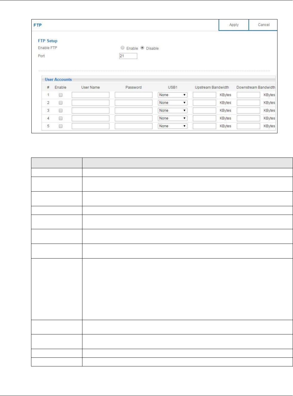
Figure 81 Expert Mode > Applications > File Sharing > FTP
The following table describes the labels in this screen.
Table 52 Expert Mode > Applications > File Sharing > FTP
LABEL DESCRIPTION
Enable FTP Select this to enable the FTP server on the NBG6617 for file sharing using FTP.
Port You may change the server port number for FTP if needed, however you must use the
same port number in order to use that service for file sharing.
User Accounts Before you can share files you need a user account. Configure the following fields to set
up a file-sharing account.
#This is the index number of the user account.
Enable This field displays whether a user account is activated or not. Select the check box to
enable the account. Clear the check box to disable the account.
User Name Enter a user name that will be allowed to access the shared files. You can enter up to 20
characters. Only letters and numbers allowed.
Password Enter the password used to access the shared files. You can enter up to 20 characters.
Only letters and numbers are allowed. The password is case sensitive.
USB1 Specify the user’s access rights to the USB storage device which is connected to the
NBG6617’s USB port.
Read & Write - The user has read and write rights, meaning that the user can create
and edit the files on the connected USB device.
Read - The user has read rights only and can not create or edit the files on the
connected USB device.
None - The user cannot access the files on the USB device(s) connected to the USB
port.
Upstream
Bandwidth
Enter the maximum bandwidth (in Kbps) allowed for incoming FTP traffic.
Downstream
Bandwidth
Enter the maximum bandwidth (in Kbps) allowed for outgoing FTP traffic.
Apply Click Apply to save your changes back to the NBG6617.
Cancel Click Cancel to begin configuring this screen afresh.
Chapter 13 Applications
NBG6617 User’s Guide
123
13.6.3 Example of Accessing Your Shared Files From a Computer
You can use Windows Explorer or FTP to access the USB storage devices connected to the
NBG6617.
This example shows you how to use Microsoft’s Windows XP to browse your shared files. Refer to
your operating system’s documentation for how to browse your file structure.
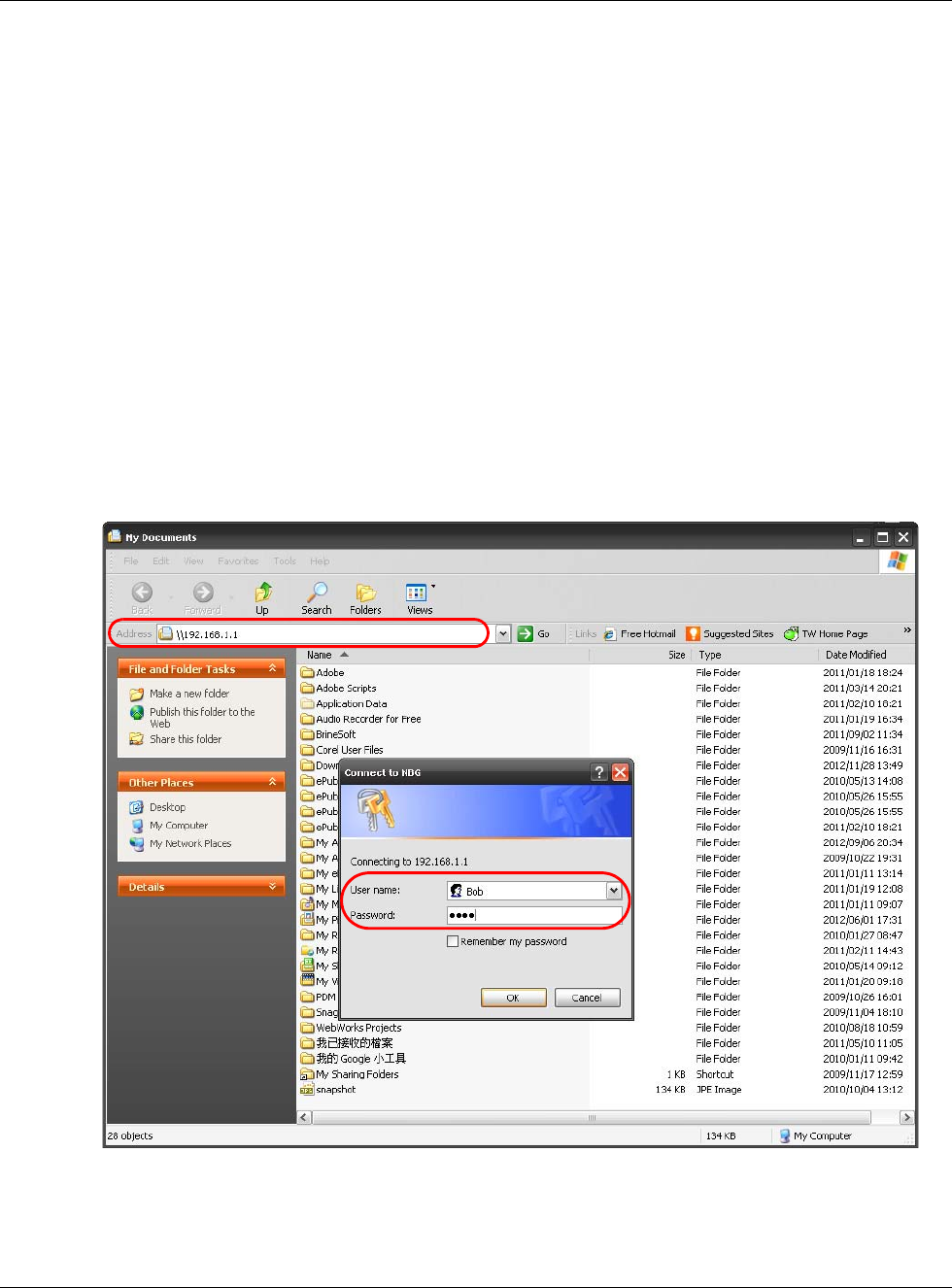
Use Windows Explorer to Share Files
You should have enabled file sharing and create a user account (Bob/1234 for example) with read
and write access to USB 1 in the Applications > File Sharing > SAMBA screen.
Open Windows Explorer to access the connected USB device using either Windows Explorer browser
or by browsing to your workgroup.
1In Windows Explorer’s Address bar type a double backslash “\\” followed by the IP address of the
NBG6617 (the default IP address of the NBG6617 in router mode is 192.168.1.1) and press
[ENTER]. A screen asking for password authentication appears. Type the user name and password
(Bob and 1234 in this example) and click OK.
Note: Once you log into the shared folder via your NBG6617, you do not have to relogin
unless you restart your computer.
Chapter 13 Applications
NBG6617 User’s Guide
124
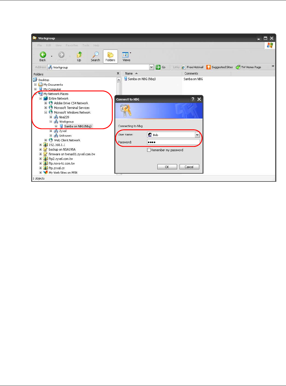
2You can also use the workgroup name to access files by browsing to the workgroup folder using the
folder tree on the left side of the screen. It is located under My Network Places. In this example
the workgroup name is the default “Workgroup”.
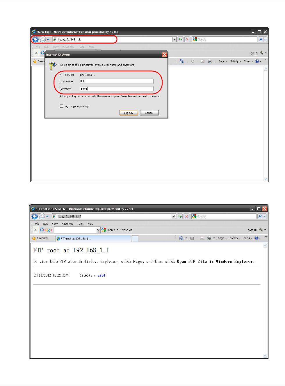
Use FTP to Share Files
You can use FTP to access the USB storage devices connected to the NBG6617. In this example, we
use the web browser to share files via FTP from the LAN. The way or screen you log into the FTP
server (on the NBG6617) varies depending on your FTP client. See your FTP client documentation
for more information.
You should have enabled file sharing and create a user account (Bob/1234 for example) with read
and write access to USB 1 in the Applications > File Sharing > FTP screen.
1In your web browser’s address or URL bar type “ftp://” followed by the IP address of the NBG6617
(the default LAN IP address of the NBG6617 in router mode is 192.168.1.1) and click Go or press
[ENTER].
Chapter 13 Applications
NBG6617 User’s Guide
125
2A screen asking for password authentication appears. Enter the user name and password (you
configured in the Applications > File Sharing > FTP screen) and click Log On.
3The screen changes and shows you the folder for the USB storage device connected to your
NBG6617. Double-click the folder to display the contents in it.
Chapter 13 Applications
NBG6617 User’s Guide
126
13.7 ONE Connect Screen
One Connect is a ZyXEL-proprietary feature. It complies with the IEEE 1905.1 standard and allows
auto-detection and auto-configuration.
If your wireless router supports ZyXEL One Connect, NBG6617 for example, you can download and
install the ZyXEL One Connect App in your mobile device to check the connection status, do speed
test, turn on or turn off the devices in your network, block or allow a device’s access and set up a
guest Wi-Fi network from the mobile device. You can even use the App to access the NBG6617’s
web configurator. The mobile device with the App installed must be connected to the NBG6617
wirelessly.
Note: You have to go to https://mycloud.zyxel.com and pair your device again when you
reset the NBG6617.
Figure 82 ZyXEL ONE Connect App
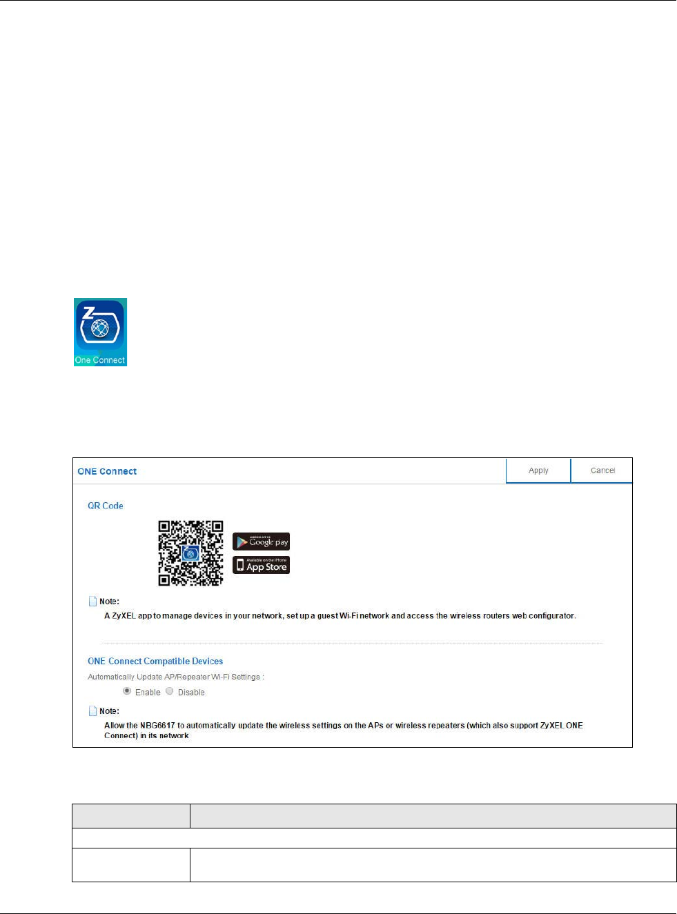
Use this screen to enable or disable Wi-Fi auto-configuration on the NBG6617.
In Expert mode, click Applications > ONE Connect to open the following screen.
Figure 83 Expert Mode > Applications > ONE Connect
The following table describes the labels in this screen.
Table 53 Expert Mode > Applications > ONE Connect
LABEL DESCRIPTION
ONE Connect
QR Code Scan the QR code and go to a website to download the ZyXEL One Connect App in your
mobile device. One is for the iTunes App Store, and the other is for Google Play.

Chapter 13 Applications
NBG6617 User’s Guide
127
13.8 Technical Reference
The following section contains additional technical information about the NBG6617 features
described in this chapter.
Customizing Keyword Blocking URL Checking
You can use commands to set how much of a website’s URL the content filter is to check for
keyword blocking. See the appendices for information on how to access and use the command
interpreter.
Domain Name or IP Address URL Checking
By default, the NBG6617 checks the URL’s domain name or IP address when performing keyword
blocking.
This means that the NBG6617 checks the characters that come before the first slash in the URL.
For example, with the URL www.zyxel.com.tw/news/pressroom.php, content filtering only searches
for keywords within www.zyxel.com.tw.
Full Path URL Checking
Full path URL checking has the NBG6617 check the characters that come before the last slash in the
URL.
For example, with the URL www.zyxel.com.tw/news/pressroom.php, full path URL checking
searches for keywords within www.zyxel.com.tw/news/.
Use the ip urlfilter customize actionFlags 6 [disable | enable] command to extend (or
not extend) the keyword blocking search to include the URL's full path.
File Name URL Checking
Filename URL checking has the NBG6617 check all of the characters in the URL.
For example, filename URL checking searches for keywords within the URL www.zyxel.com.tw/
news/pressroom.php.
One Connect Compatible Devices
Automatically
Update AP/
Repeater Wi-Fi
Settings
Select Enable to allow the NBG6617 to automatically update the wireless settings on
the APs or wireless repeaters (which also support ZyXEL One Connect) in its network.
Select Disable to turn this feature off if you want to have the APs or repeaters in the
network use different wireless settings.
Apply Click Apply to save your changes back to the NBG6617.
Cancel Click Cancel to begin configuring this screen afresh.
Table 53 Expert Mode > Applications > ONE Connect
LABEL DESCRIPTION

Chapter 13 Applications
NBG6617 User’s Guide
128
Use the ip urlfilter customize actionFlags 8 [disable | enable] command to extend (or
not extend) the keyword blocking search to include the URL's complete filename.
NAT Traversal
UPnP NAT traversal automates the process of allowing an application to operate through NAT. UPnP
network devices can automatically configure network addressing, announce their presence in the
network to other UPnP devices and enable exchange of simple product and service descriptions.
NAT traversal allows the following:
• Dynamic port mapping
• Learning public IP addresses
• Assigning lease times to mappings
Windows Messenger is an example of an application that supports NAT traversal and UPnP.
See the NAT chapter for more information on NAT.
Cautions with UPnP
The automated nature of NAT traversal applications in establishing their own services and opening
firewall ports may present network security issues. Network information and configuration may also
be obtained and modified by users in some network environments.
When a UPnP device joins a network, it announces its presence with a multicast message. For
security reasons, the NBG6617 allows multicast messages on the LAN only.
All UPnP-enabled devices may communicate freely with each other without additional configuration.
Disable UPnP if this is not your intention.
NBG6617 User’s Guide
129
CHAPTER 14
Security
14.1 Overview
Use these screens to enable and configure the firewall that protects your NBG6617 and your LAN
from unwanted or malicious traffic.
Enable the firewall to protect your LAN computers from attacks by hackers on the Internet and
control access between the LAN and WAN. By default the firewall:
• allows traffic that originates from your LAN computers to go to all of the networks.
• blocks traffic that originates on the other networks from going to the LAN.
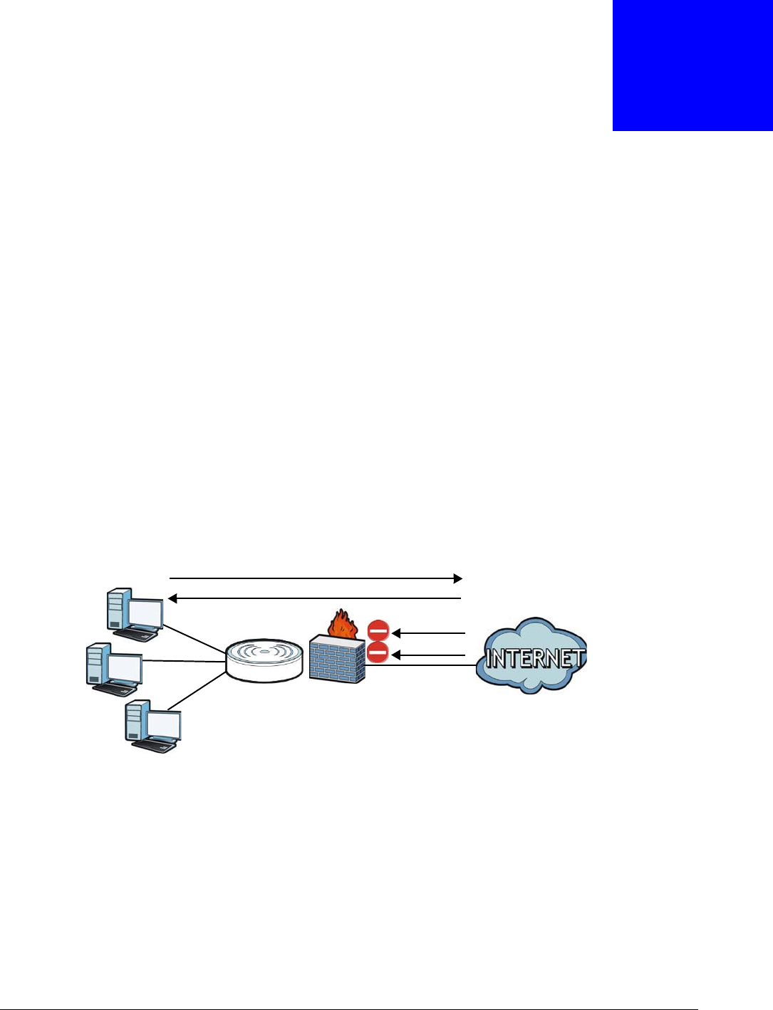
The following figure illustrates the default firewall action. User A can initiate an IM (Instant
Messaging) session from the LAN to the WAN (1). Return traffic for this session is also allowed (2).
However other traffic initiated from the WAN is blocked (3 and 4).
Figure 84 Default Firewall Action
14.1.1 What You Can Do
•Use the IPv4 Firewall screen to enable or disable the NBG6617’s IPv4 firewall (Section 14.2 on
page 130).
•Use the IPv6 Firewallscreen to enable or disable the NBG6617’s IPv6 firewall (Section 14.3 on
page 132).
14.1.2 What You Need To Know
The following terms and concepts may help as you read through this chapter.
WAN
LAN
3
4
1
2
A

Chapter 14 Security
NBG6617 User’s Guide
130
About the NBG6617 Firewall
The NBG6617’s firewall feature physically separates the LAN and the WAN and acts as a secure
gateway for all data passing between the networks.
It is a stateful inspection firewall and is designed to protect against Denial of Service attacks when
activated (click the IPv4 Firewall or IPv6 Firewall tab under Security and then click the Enable
Firewall check box). The NBG6617's purpose is to allow a private Local Area Network (LAN) to be
securely connected to the Internet. The NBG6617 can be used to prevent theft, destruction and
modification of data, as well as log events, which may be important to the security of your network.
The NBG6617 is installed between the LAN and a broadband modem connecting to the Internet.
This allows it to act as a secure gateway for all data passing between the Internet and the LAN.
The NBG6617 has one Ethernet WAN port and four Ethernet LAN ports, which are used to physically
separate the network into two areas.The WAN (Wide Area Network) port attaches to the broadband
(cable or DSL) modem to the Internet.
The LAN (Local Area Network) port attaches to a network of computers, which needs security from
the outside world. These computers will have access to Internet services such as e-mail, FTP and
the World Wide Web. However, "inbound access" is not allowed (by default) unless the remote host
is authorized to use a specific service.
Guidelines For Enhancing Security With Your Firewall
1Change the default password via Web Configurator.
2Think about access control before you connect to the network in any way, including attaching a
modem to the port.
3Limit who can access your router.
4Don't enable any local service (such as NTP) that you don't use. Any enabled service could present
a potential security risk. A determined hacker might be able to find creative ways to misuse the
enabled services to access the firewall or the network.
5For local services that are enabled, protect against misuse. Protect by configuring the services to
communicate only with specific peers, and protect by configuring rules to block packets for the
services at specific interfaces.
6Protect against IP spoofing by making sure the firewall is active.
7Keep the firewall in a secured (locked) room.
14.2 IPv4 Firewall Screen
Use this screen to enable or disable the NBG6617’s IPv4 firewall, and set up firewall logs. Click
Expert Mode > Security > IPv4 Firewall to open the firewall setup screen.
Chapter 14 Security
NBG6617 User’s Guide
131
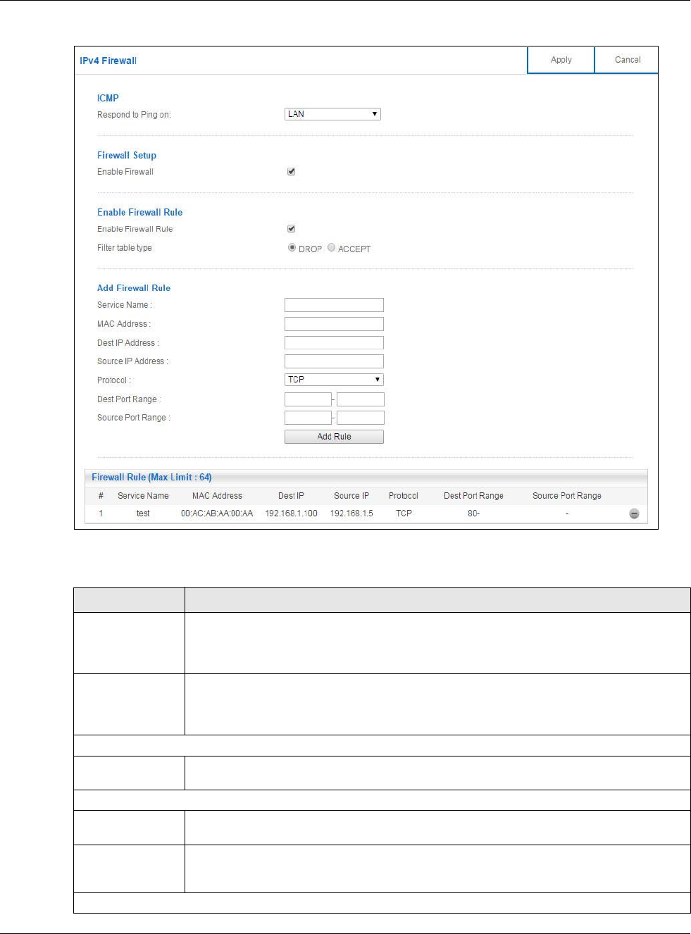
Figure 85 Expert Mode > Security > IPv4 Firewall
The following table describes the labels in this screen.
Table 54 Expert Mode > Security > IPv4 Firewall
LABEL DESCRIPTION
ICMP Internet Control Message Protocol is a message control and error-reporting protocol
between a host server and a gateway to the Internet. ICMP uses Internet Protocol (IP)
datagrams, but the messages are processed by the TCP/IP software and directly apparent
to the application user.
Respond to Ping
on
The NBG6617 will not respond to any incoming Ping requests when Disable is selected.
Select LAN to reply to incoming LAN Ping requests. Select WAN to reply to incoming
WAN Ping requests. Otherwise select LAN&WAN to reply to all incoming LAN and WAN
Ping requests.
Firewall Setup
Enable Firewall Select this check box to activate the firewall. The NBG6617 performs access control and
protects against Denial of Service (DoS) attacks when the firewall is activated.
Enable Firewall Rule
Enable Firewall
Rule
Select this check box to activate the firewall rules that you define (see Add Firewall Rule
below).
Filter table type Select DROP to silently discard the packets which meet the firewall rules. The others are
accepted.Select ACCEPT to allow the passage of the packets which meet the firewall
rules. The others are blocked.
Add Firewall Rule

Chapter 14 Security
NBG6617 User’s Guide
132
14.3 IPv6 Firewall Screen
This chapter shows you how to enable and create IPv6 firewall rules to block unwanted IPv6 traffic.
Service Name Enter a name that identifies or describes the firewall rule.
MAC Address Enter the MAC address of the computer for which the firewall rule applies.
Dest IP Address Enter the IP address of the computer to which traffic for the application or service is
entering.
The NBG6617 applies the firewall rule to traffic initiating from this computer.
Source IP Address Enter the IP address of the computer that initializes traffic for the application or service.
The NBG6617 applies the firewall rule to traffic initiating from this computer.
Protocol Select the protocol (TCP, UDP or ICMP) used to transport the packets for which you want
to apply the firewall rule.
Dest Port Range This is the port number/range of the destination that define the traffic type, for example
TCP port 80 defines web traffic.
Source Port
Range
This is the port number/range of the source that define the traffic type, for example TCP
port 80 defines web traffic.
Add Rule Click Add Rule to save the firewall rule.
Firewall Rule
# This is your firewall rule number. The ordering of your rules is important as rules are
applied in turn.
Service Name This is a name that identifies or describes the firewall rule.
MAC addresse This is the MAC address of the computer for which the firewall rule applies.
Dest IP This is the IP address of the computer to which traffic for the application or service is
entering.
Source IP This is the IP address of the computer from which traffic for the application or service is
initialized.
Protocol This is the protocol (TCP, UDP or ICMP) used to transport the packets for which you
want to apply the firewall rule.
Dest Port Range This is the port number/range of the destination that define the traffic type, for example
TCP port 80 defines web traffic.
Source Port
Range
This is the port number/range of the source that define the traffic type, for example TCP
port 80 defines web traffic.
Click to remove the firewall rule.
Apply Click Apply to save the settings.
Cancel Click Cancel to start configuring this screen again.
Table 54 Expert Mode > Security > IPv4 Firewall (continued)
LABEL DESCRIPTION
Chapter 14 Security
NBG6617 User’s Guide
133
Click Expert Mode > Security > IPv6 Firewall. The IPv6 Firewall screen appears as shown.
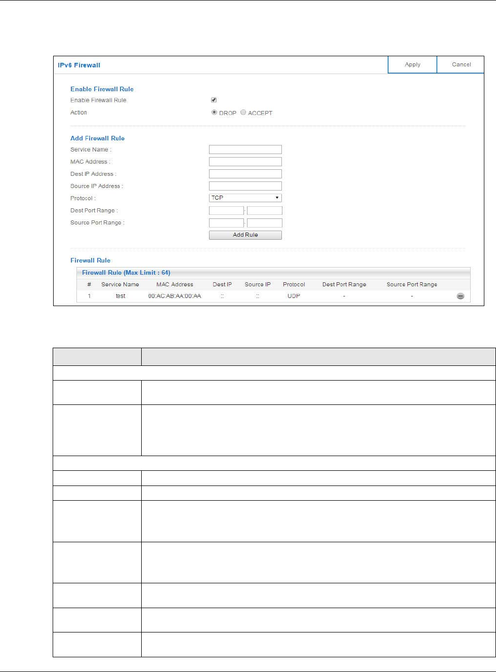
Figure 86 Expert Mode > Security > IPv6 Firewall
The following table describes the labels in this screen.
Table 55 Expert Mode > Security > IPv6 Firewall
LABEL DESCRIPTION
Enable Firewall Rule
Enable Firewall Rule Select this check box to activate the firewall rules that you define (see Add Firewall
Rule below).
Action Select DROP to silently discard the packets which meet the firewall rules. The others
are accepted.
Select ACCEPT to allow the passage of the packets which meet the firewall rules. The
others are blocked.
Add Firewall Rule
Service Name Enter a name that identifies or describes the firewall rule.
MAC Address Enter the MAC address of the computer for which the firewall rule applies.
Dest IP Address Enter the IPv6 address of the computer to which traffic for the application or service is
entering.
The NBG6617 applies the firewall rule to traffic destined for this computer.
Source IP Address Enter the IPv6 address of the computer that initializes traffic for the application or
service.
The NBG6617 applies the firewall rule to traffic initiating from this computer.
Protocol Select the protocol (TCP, UDP or ICMPv6) used to transport the packets for which you
want to apply the firewall rule.
Dest Port Range Enter the port number/range of the destination that defines the traffic type, for
example TCP port 80 defines web traffic.
Source Port Range Enter the port number/range of the source that defines the traffic type, for example
TCP port 80 defines web traffic.

Chapter 14 Security
NBG6617 User’s Guide
134
Add Rule Click Add Rule to save the firewall rule.
Firewall Rule
#This is your firewall rule number. The ordering of your rules is important as rules are
applied in turn.
ServiceName This is a name that identifies or describes the firewall rule.
MAC Address This is the MAC address of the computer for which the firewall rule applies.
Dest IP This is the IP address of the computer to which traffic for the application or service is
entering.
Source IP This is the IP address of the computer to which traffic for the application or service is
initialized.
Protocol This is the protocol (TCP, UDP or ICMPv6) used to transport the packets for which you
want to apply the firewall rule.
Dest Port Range This is the port number/range of the destination that defines the traffic type, for
example TCP port 80 defines web traffic.
Source Port Range This is the port number/range of the source that defines the traffic type, for example
TCP port 80 defines web traffic.
Click to remove the firewall rule.
Apply Click Apply to save the settings.
Cancel Click Cancel to restore your previously saved settings.
Table 55 Expert Mode > Security > IPv6 Firewall (continued)
LABEL DESCRIPTION

NBG6617 User’s Guide
135
CHAPTER 15
Maintenance
15.1 Overview
This chapter provides information on the Maintenance screens.
15.2 What You Can Do
•Use the General screen to set the timeout period of the management session (Section 15.3 on
page 135).
•Use the Password screen to change your NBG6617’s system password (Section 15.4 on page
136).
•Use the Time screen to change your NBG6617’s time and date (Section 15.5 on page 137).
•Use the Firmware Upgrade screen to upload firmware to your NBG6617 (Section 15.6 on page
139).
•Use the Backup/Restore screen to view information related to factory defaults, backup
configuration, and restoring configuration (Section 15.7 on page 140).
•Use the Restart screen to reboot the NBG6617 without turning the power off (Section 15.8 on
page 141).
•Use the Language screen to change the language for the Web Configurator (Section 15.9 on
page 141).
•Use the Remote Management screen to configure the interface/s from which the NBG6617 can
be managed remotely and specify a secure client that can manage the NBG6617. (Section 15.10
on page 142).
•Use the Log screen to see the logs for the activity on the NBG6617 (Section 15.11 on page 145).
•Use the Operation Mode screen to select how you want to use your NBG6617 (Section 15.13 on
page 147).
15.3 General Screen
Use this screen to set the management session timeout period. Click Expert Mode >
Maintenance > General. The following screen displays.
Chapter 15 Maintenance
NBG6617 User’s Guide
136
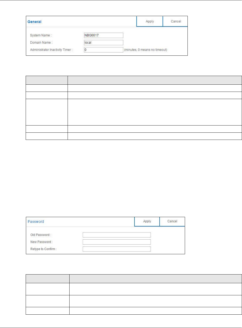
Figure 87 Expert Mode > Maintenance > General
The following table describes the labels in this screen.
15.4 Password Screen
It is strongly recommended that you change your NBG6617's password.
If you forget your NBG6617's password (or IP address), you will need to reset the device. See
Section 15.8 on page 141 for details.
Click Expert Mode > Maintenance > Password. The screen appears as shown.
Figure 88 Expert Mode > Maintenance > Password
The following table describes the labels in this screen.
Table 56 Expert Mode > Maintenance > General
LABEL DESCRIPTION
System Name System Name is a unique name to identify the NBG6617 in an Ethernet network.
Domain Name Enter the domain name you want to give to the NBG6617.
Administrator
Inactivity Timer
Type how many minutes a management session can be left idle before the session times
out. The default is 5 minutes. After it times out you have to log in with your password
again. Very long idle timeouts may have security risks. A value of "0" means a
management session never times out, no matter how long it has been left idle (not
recommended).
Apply Click Apply to save your changes back to the NBG6617.
Cancel Click Cancel to begin configuring this screen afresh.
Table 57 Expert Mode > Maintenance > Password
LABEL DESCRIPTION
Old Password Type the default password or the existing password you use to access the system in
this field.
New Password Type your new system password (up to 30 characters). Note that as you type a
password, the screen displays an asterisk (*) for each character you type.
Retype to Confirm Type the new password again in this field.
Chapter 15 Maintenance
NBG6617 User’s Guide
137
15.5 Time Screen
Use this screen to configure the NBG6617’s time based on your local time zone. To change your
NBG6617’s time and date, click Expert Mode > Maintenance > Time. The screen appears as
shown.
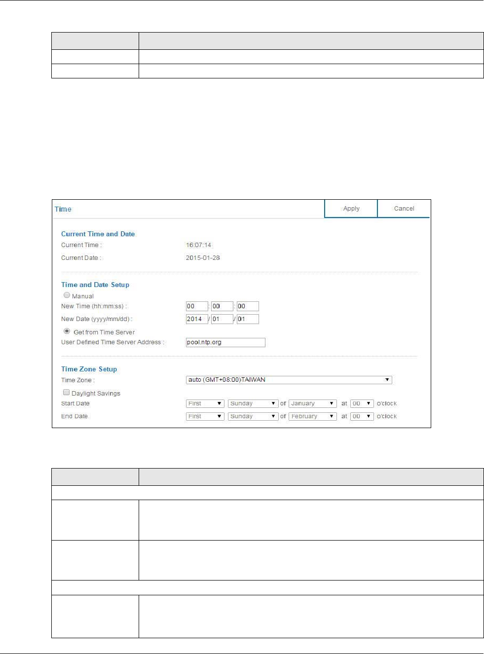
Figure 89 Expert Mode > Maintenance > Time
The following table describes the labels in this screen.
Apply Click Apply to save your changes back to the NBG6617.
Cancel Click Cancel to begin configuring this screen afresh.
Table 57 Expert Mode > Maintenance > Password (continued)
LABEL DESCRIPTION
Table 58 Expert Mode > Maintenance > Time
LABEL DESCRIPTION
Current Time and Date
Current Time This field displays the time of your NBG6617.
Each time you reload this page, the NBG6617 synchronizes the time with the time
server.
Current Date This field displays the date of your NBG6617.
Each time you reload this page, the NBG6617 synchronizes the date with the time
server.
Time and Date Setup
Manual Select this radio button to enter the time and date manually. If you configure a new
time and date, Time Zone and Daylight Saving at the same time, the new time and date
you entered has priority and the Time Zone and Daylight Saving settings do not affect
it.

Chapter 15 Maintenance
NBG6617 User’s Guide
138
New Time
(hh:mm:ss)
This field displays the last updated time from the time server or the last time
configured manually.
When you select Manual, enter the new time in this field and then click Apply.
New Date
(yyyy/mm/dd)
This field displays the last updated date from the time server or the last date configured
manually.
When you select Manual, enter the new date in this field and then click Apply.
Get from Time
Server
Select this radio button to have the NBG6617 get the time and date from the time
server you specified below.
User Defined Time
Server Address
Select User Defined Time Server Address and enter the IP address or URL (up to 20
extended ASCII characters in length) of your time server. Check with your ISP/network
administrator if you are unsure of this information.
Time Zone Setup
Time Zone Choose the time zone of your location. This will set the time difference between your
time zone and Greenwich Mean Time (GMT).
Daylight Savings Daylight saving is a period from late spring to early fall when many countries set their
clocks ahead of normal local time by one hour to give more daytime light in the
evening.
Select this option if you use Daylight Saving Time.
Start Date Configure the day and time when Daylight Saving Time starts if you selected Daylight
Savings. The at field uses the 24 hour format. Here are a couple of examples:
Daylight Saving Time starts in most parts of the United States on the second Sunday of
March. Each time zone in the United States starts using Daylight Saving Time at 2 A.M.
local time. So in the United States you would select Second, Sunday, March and
select 2 in the at field.
Daylight Saving Time starts in the European Union on the last Sunday of March. All of
the time zones in the European Union start using Daylight Saving Time at the same
moment (1 A.M. GMT or UTC). So in the European Union you would select Last,
Sunday, March. The time you select in the at field depends on your time zone. In
Germany for instance, you would select 2 because Germany's time zone is one hour
ahead of GMT or UTC (GMT+1).
End Date Configure the day and time when Daylight Saving Time ends if you selected Daylight
Savings. The at field uses the 24 hour format. Here are a couple of examples:
Daylight Saving Time ends in the United States on the first Sunday of November. Each
time zone in the United States stops using Daylight Saving Time at 2 A.M. local time.
So in the United States you would select First, Sunday, November and select 2 in the
at field.
Daylight Saving Time ends in the European Union on the last Sunday of October. All of
the time zones in the European Union stop using Daylight Saving Time at the same
moment (1 A.M. GMT or UTC). So in the European Union you would select Last,
Sunday, October. The time you select in the at field depends on your time zone. In
Germany for instance, you would select 2 because Germany's time zone is one hour
ahead of GMT or UTC (GMT+1).
Apply Click Apply to save your changes back to the NBG6617.
Cancel Click Cancel to begin configuring this screen afresh.
Table 58 Expert Mode > Maintenance > Time (continued)
LABEL DESCRIPTION
Chapter 15 Maintenance
NBG6617 User’s Guide
139
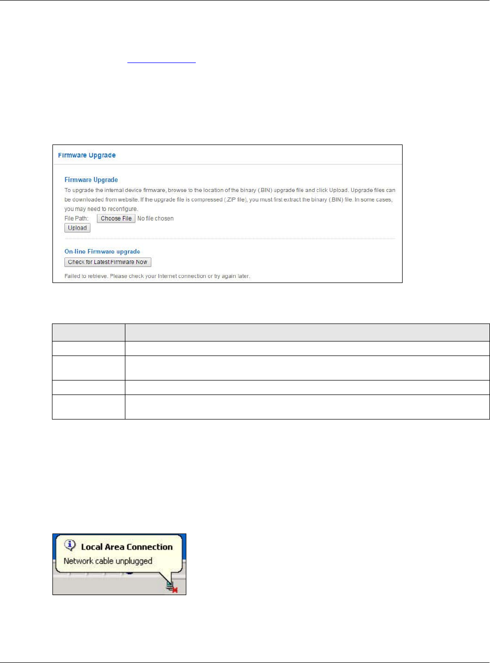
15.6 Firmware Upgrade Screen
Find firmware at www.zyxel.com in a file that uses the version number and project code with a
“*.bin” extension, e.g., “V1.00(AARO.0).bin”. The upload process uses HTTP (Hypertext Transfer
Protocol) and may take up to two minutes. After a successful upload, the system will reboot.
Click Expert Mode > Maintenance > Firmware Upgrade. Follow the instructions in this screen
to upload firmware to your NBG6617.
Figure 90 Expert Mode > Maintenance > Firmware Upgrade
The following table describes the labels in this screen.
Note: Do not turn off the NBG6617 while firmware upload is in progress!
After you see the Firmware Upload In Process screen, wait two minutes before logging into the
NBG6617 again.
The NBG6617 automatically restarts in this time causing a temporary network disconnect. In some
operating systems, you may see the following icon on your desktop.
Figure 91 Network Temporarily Disconnected
After two minutes, log in again and check your new firmware version in the Status screen.
If the upload was not successful, an error message appears. Click Return to go back to the
Firmware Upgrade screen.
Table 59 Expert Mode > Maintenance > Firmware Upgrade
LABEL DESCRIPTION
File Path Click Choose File to find the location of the file you want to upload in this field.
Choose File Click Choose File to find the .bin file you want to upload. Remember that you must
decompress compressed (.zip) files before you can upload them.
Upload Click Upload to begin the upload process. This process may take up to two minutes.
Check for Latest
Firmware Now
Click this to check for the latest updated firmware.
Chapter 15 Maintenance
NBG6617 User’s Guide
140
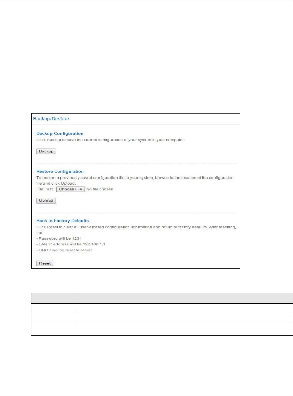
15.7 Backup/Restore Screen
Backup configuration allows you to back up (save) the NBG6617’s current configuration to a file on
your computer. Once your NBG6617 is configured and functioning properly, it is highly
recommended that you back up your configuration file before making configuration changes. The
backup configuration file will be useful in case you need to return to your previous settings.
Restore configuration allows you to upload a new or previously saved configuration file from your
computer to your NBG6617.
Click Expert Mode > Maintenance > Backup/Restore. Information related to factory defaults,
backup configuration, and restoring configuration appears as shown next.
Figure 92 Expert Mode > Maintenance > Backup/Restore
The following table describes the labels in this screen.
Table 60 Expert Mode > Maintenance > Backup/Restore
LABEL DESCRIPTION
Backup Click Backup to save the NBG6617’s current configuration to your computer.
File Path Click Choose File to find the location of the file you want to upload in this field.
Choose File Click Choose File to find the file you want to upload. Remember that you must
decompress compressed (.ZIP) files before you can upload them.
Chapter 15 Maintenance
NBG6617 User’s Guide
141
Note: If you uploaded the default configuration file you may need to change the IP
address of your computer to be in the same subnet as that of the default NBG6617
IP address (192.168.1.1). See Appendix B on page 162 for details on how to set up
your computer’s IP address.
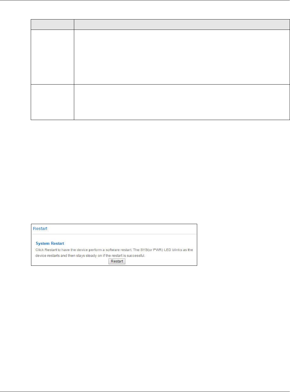
15.8 Restart Screen
System restart allows you to reboot the NBG6617 without turning the power off.
Click Expert Mode > Maintenance > Restart to open the following screen.
Figure 93 Expert Mode > Maintenance > Restart
Click Restart to have the NBG6617 reboot. This does not affect the NBG6617's configuration.
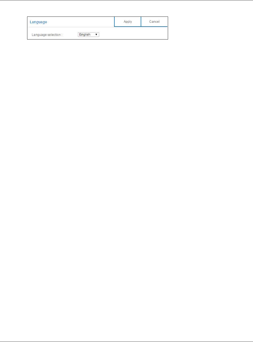
15.9 Language Screen
Use this screen to change the language for the Web Configurator.
Select the language you prefer and click Apply. The Web Configurator language changes after a
while without restarting the NBG6617. Click Expert Mode > Maintenance > Language to open
the following screen.
Upload Click Upload to begin the upload process.
Note: Do not turn off the NBG6617 while configuration file upload is in progress.
After you see a “configuration upload successful” screen, you must then wait one minute
before logging into the NBG6617 again. The NBG6617 automatically restarts in this time
causing a temporary network disconnect.
If you see an error screen, click Back to return to the Backup/Restore screen.
Reset Pressing the Reset button in this section clears all user-entered configuration information
and returns the NBG6617 to its factory defaults.
You can also press the RESET button on the rear panel to reset the factory defaults of your
NBG6617. Refer to the chapter about introducing the Web Configurator for more
information on the RESET button.
Table 60 Expert Mode > Maintenance > Backup/Restore (continued)
LABEL DESCRIPTION
Chapter 15 Maintenance
NBG6617 User’s Guide
142
Figure 94 Expert Mode > Maintenance > Language
15.10 Remote Management Screen
Remote Management allows you to manage your NBG6617 from a remote location through the
LAN/WLAN or WAN interface.
15.10.1 Remote Access
Use this screen to change your NBG6617’s remote management settings. You can use Telnet, HTTP
or HTTPS to access and manage the NBG6617.
Click Expert Mode > Maintenance > Remote Management > Remote Access to open the
following screen.

Chapter 15 Maintenance
NBG6617 User’s Guide
143
Figure 95 Expert Mode > Maintenance > Remote Management > Remote Access
The following table describes the labels in this screen.
Table 61 Expert Mode > Maintenance > Remote Management > WAN Access
LABEL DESCRIPTION
WWW
Port You may change the server port number for a service if needed, however you must use the
same port number in order to use that service for remote management.
Access Status Select the interface(s) through which a computer may access the NBG6617 using this
service.
Secured Client
IP Address
Select All to allow all computes to access the NBG6617.
Otherwise, check Selected and specify the IP address of the computer that can access the
NBG6617.
Telnet
Chapter 15 Maintenance
NBG6617 User’s Guide
144
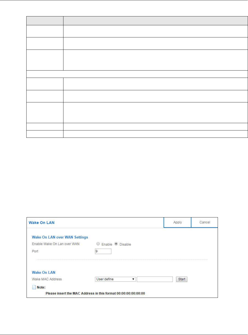
15.10.2 Wake On LAN
Wake On LAN (WoL) allows you to remotely turn on a device on the network, such as a computer,
storage device or media server. To use this feature the remote hardware (for example the network
adapter on a computer) must support Wake On LAN using the “Magic Packet” method.
You need to know the MAC address of the remote device. It may be on a label on the device.
Use this screen to remotely turn on a device on the network. Click the Expert Mode >
Maintenance > Remote Management > Wake On LAN to open the following screen.
Figure 96 Expert Mode > Maintenance > Remote Management > Wake On LAN
Port You may change the server port number for a service if needed, however you must use the
same port number in order to use that service for remote management.
Access Status Select the interface(s) through which a computer may access the NBG6617 using this
service.
Secured Client
IP Address
Select All to allow all computes to access the NBG6617.
Otherwise, check Selected and specify the IP address of the computer that can access the
NBG6617.
HTTPS
Port You may change the server port number for a service if needed, however you must use the
same port number in order to use that service for remote management.
Access Status Select the interface(s) through which a computer may access the NBG6617 using this
service.
Secured Client
IP Address
Select All to allow all computes to access the NBG6617.
Otherwise, check Selected and specify the IP address of the computer that can access the
NBG6617.
Apply Click Apply to save your changes back to the NBG6617.
Cancel Click Cancel to begin configuring this screen afresh.
Table 61 Expert Mode > Maintenance > Remote Management > WAN Access
LABEL DESCRIPTION
Chapter 15 Maintenance
NBG6617 User’s Guide
145
The following table describes the labels in this screen.
15.11 Log Screen
The Web Configurator allows you to look at all of the NBG6617’s logs in one location.
You can configure which logs to display in the Log screen. Select the logs you wish to display. Click
Apply to save your settings. Click Cancel to start the screen afresh.
Use this screen to see the logged messages for the NBG6617. The log wraps around and deletes the
old entries after it fills. Select what logs you want to see from the Display drop list. The log choices
depend on your settings above this screen. Click Refresh to renew the log screen. Click Clear Log
to delete all the logs.
Table 62 Expert Mode > Maintenance > Remote Management > Wake On LAN
LABEL DESCRIPTION
Wake On LAN over WAN Settings
Enable Wake On
LAN over WAN
Select Enable to have the NBG6617 forward a WoL “Magic Packet” to all devices on the
LAN if the packet comes from the WAN or remote network and uses the port number
specified in the Port field. A LAN device whose hardware supports Wake on LAN then will
be powered on if it is turned off previously.
Port Type a port number from which a WoL packet is forwarded to the LAN.
Wake On LAN
Wake MAC
Address
This field displays the hostname and MAC address of the LAN device by default. Otherwise,
select User define to enter the MAC Address of the device on the network that will be
turned on.
A MAC address consists of six hexadecimal character pairs.
Start Click this to have the NBG6617 generate a WoL packet and forward it to turn the specified
device on.
A screen pops up displaying MAC address error if you input the MAC address incorrectly.
Apply Click Apply to save your changes back to the NBG6617.
Cancel Click Cancel to begin configuring this screen afresh.
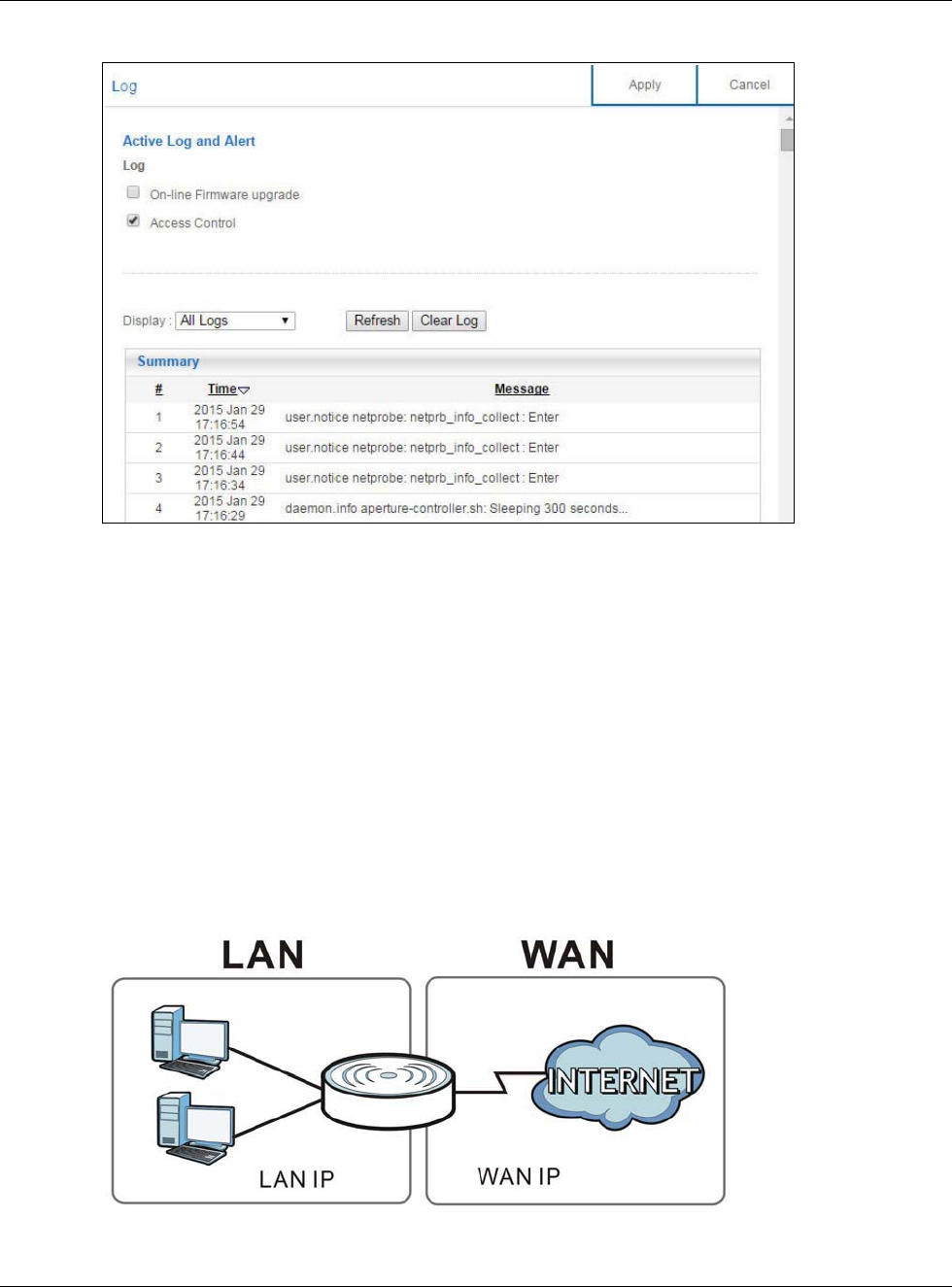
Chapter 15 Maintenance
NBG6617 User’s Guide
146
Figure 97 Expert Mode > Maintenance > Log
15.12 System Operation Mode Overview
The Sys OP Mode (System Operation Mode) function lets you configure your NBG6617 as a router
or access point. You can choose between Router Mode, and Access Point Mode depending on
your network topology and the features you require from your device.
The following describes the device modes available in your NBG6617.
Router
A router connects your local network with another network, such as the Internet. The router has
two IP addresses, the LAN IP address and the WAN IP address.
Figure 98 LAN and WAN IP Addresses in Router Mode
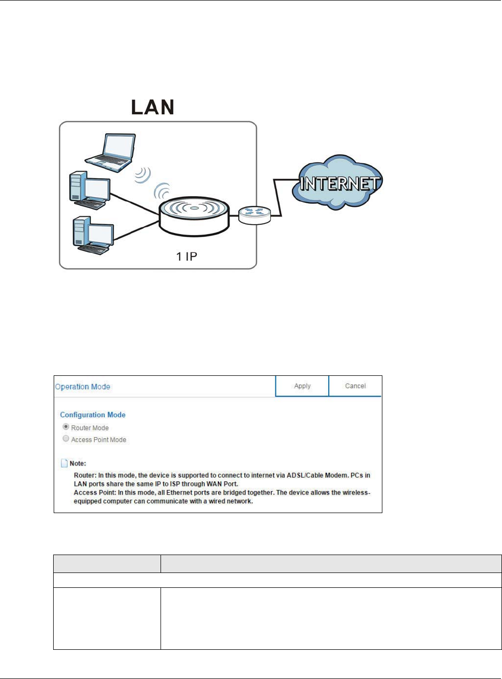
Chapter 15 Maintenance
NBG6617 User’s Guide
147
Access Point
An access point enabled all ethernet ports to be bridged together and be in the same subnet. To
connect to the Internet, another device, such as a router, is required.
Figure 99 Access Point Mode
15.13 Operation Mode Screen
Use this screen to select how you want to use your NBG6617.
Figure 100 Expert Mode > Maintenance > Operation Mode
The following table describes the labels in the Operation Mode screen.
Table 63 Expert Mode > Maintenance > Operation Mode
LABEL DESCRIPTION
Configuration Mode
Router Mode Select Router Mode if your device routes traffic between a local network and
another network such as the Internet. This mode offers services such as a firewall
or bandwidth management.
You can configure the IP address settings on your WAN port. Contact your ISP or
system administrator for more information on appropriate settings.
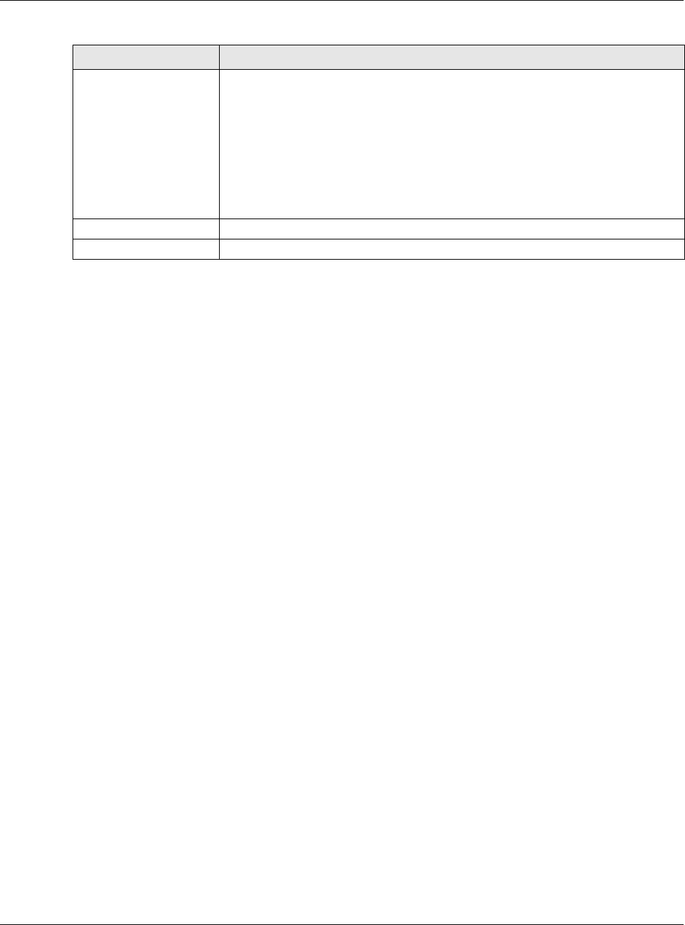
Chapter 15 Maintenance
NBG6617 User’s Guide
148
Note: If you select the incorrect system operation Mode you may not be able to connect
to the Internet.
Access Point Mode Select Access Point Mode if your device bridges traffic between clients on the
same network.
•In Access Point Mode, all Ethernet ports have the same IP address.
• All ports on the rear panel of the device are LAN ports, including the port
labeled WAN. There is no WAN port.
• The DHCP server on your device is disabled.
• Router functions (such as NAT, bandwidth management, remote management,
firewall and so on) are not available when the NBG6617 is in Access Point
Mode.
• The IP address of the device on the local network is set to 192.168.1.2.
Apply Click Apply to save your settings.
Cancel Click Cancel to return your settings to the default (Router).
Table 63 Expert Mode > Maintenance > Operation Mode (continued)
LABEL DESCRIPTION

NBG6617 User’s Guide
149
CHAPTER 16
Troubleshooting
16.1 Overview
This chapter offers some suggestions to solve problems you might encounter. The potential
problems are divided into the following categories.
•Power, Hardware Connections, and LEDs
•NBG6617 Access and Login
•Internet Access
•Resetting the NBG6617 to Its Factory Defaults
•Wireless Connections
•USB Device Problems
16.2 Power, Hardware Connections, and LEDs
The NBG6617 does not turn on. None of the LEDs turn on.
1Make sure you are using the power adaptor or cord included with the NBG6617.
2Make sure the power adaptor or cord is connected to the NBG6617 and plugged in to an appropriate
power source. Make sure the power source is turned on.
3Disconnect and re-connect the power adaptor or cord to the NBG6617.
4If the problem continues, contact the vendor.
One of the LEDs does not behave as expected.
1Make sure you understand the normal behavior of the LED. See Section 1.7 on page 12.
2Check the hardware connections. See the Quick Start Guide.
3Inspect your cables for damage. Contact the vendor to replace any damaged cables.
4Disconnect and re-connect the power adaptor to the NBG6617.

Chapter 16 Troubleshooting
NBG6617 User’s Guide
150
5If the problem continues, contact the vendor.
16.3 NBG6617 Access and Login
I don’t know the IP address of my NBG6617.
6The default IP address of the NBG6617 in Router Mode is 192.168.1.1. If the NBG6617 obtains a
WAN IP address in the same subnet as the LAN IP address 192.168.1.1, the default LAN IP address
will be changed to 10.0.0.1 automatically. See Auto-IP Change on page 64 for more information.
The default IP address of the NBG6617 in Access Point Mode is 192.168.1.2.
7If you changed the IP address and have forgotten it, you might get the IP address of the NBG6617
in Router Mode by looking up the IP address of the default gateway for your computer. To do this
in most Windows computers, click Start > Run, enter cmd, and then enter ipconfig. The IP
address of the Default Gateway might be the IP address of the NBG6617 (it depends on the
network), so enter this IP address in your Internet browser.
8If your NBG6617 in Access Point Mode is a DHCP client, you can find your IP address from the
DHCP server. This information is only available from the DHCP server which allocates IP addresses
on your network. Find this information directly from the DHCP server or contact your system
administrator for more information.
9Reset your NBG6617 to change all settings back to their default. This means your current settings
are lost. See Section 16.5 on page 153 in the Troubleshooting for information on resetting your
NBG6617.
I forgot the password.
1The default password is 1234.
2If this does not work, you have to reset the device to its factory defaults. See Section 16.5 on page
153.
I cannot see or access the Login screen in the Web Configurator.
1Make sure you are using the correct IP address.
2The default IP address of the NBG6617 in Router Mode is 192.168.1.1. If the NBG6617 obtains a
WAN IP address in the same subnet as the LAN IP address 192.168.1.1, the default LAN IP address
will be changed to 10.0.0.1 automatically. See Auto-IP Change on page 64 for more information.
The default IP address of the NBG6617 in Access Point Mode is 192.168.1.2.
• If you changed the IP address (Section 12.4 on page 100), use the new IP address.

Chapter 16 Troubleshooting
NBG6617 User’s Guide
151
• If you changed the IP address and have forgotten it, see the troubleshooting suggestions for I
don’t know the IP address of my NBG6617.
3Check the hardware connections, and make sure the LEDs are behaving as expected. See the Quick
Start Guide.
4Make sure your Internet browser does not block pop-up windows and has JavaScript and Java
enabled.
5Make sure your computer is in the same subnet as the NBG6617. (If you know that there are
routers between your computer and the NBG6617, skip this step.)
• If there is a DHCP server on your network, make sure your computer is using a dynamic IP
address. See Section 12.4 on page 100.
• If there is no DHCP server on your network, make sure your computer’s IP address is in the
same subnet as the NBG6617. See Section 12.4 on page 100.
6Reset the device to its factory defaults, and try to access the NBG6617 with the default IP address.
See Section 1.5 on page 11.
7If the problem continues, contact the network administrator or vendor, or try one of the advanced
suggestions.
Advanced Suggestions
• Try to access the NBG6617 using another service, such as Telnet. If you can access the
NBG6617, check the remote management settings and firewall rules to find out why the
NBG6617 does not respond to HTTP.
• If your computer is connected to the WAN port or is connected wirelessly, use a computer that is
connected to a LAN/ETHERNET port.
I can see the Login screen, but I cannot log in to the NBG6617.
1Make sure you have entered the password correctly. The default password is 1234. This field is
case-sensitive, so make sure [Caps Lock] is not on.
2This can happen when you fail to log out properly from your last session. Try logging in again after
5 minutes.
3Disconnect and re-connect the power adaptor or cord to the NBG6617.
4If this does not work, you have to reset the device to its factory defaults. See Section 16.5 on page
153.
16.4 Internet Access
I cannot access the Internet.

Chapter 16 Troubleshooting
NBG6617 User’s Guide
152
1Check the hardware connections, and make sure the LEDs are behaving as expected. See the Quick
Start Guide.
2Go to Expert > Maintenance > Operation Mode. Check your System Operation Mode setting.
• If the NBG6617 is in Router Mode, make sure the WAN port is connected to a broadband
modem or router with Internet access. Your computer and the NBG6617 should be in the same
subnet.
• If the NBG6617 is in Access Point Mode, make sure the WAN port is connected to a
broadband modem or router with Internet access and your computer is set to obtain an
dynamic IP address.
3If the NBG6617 is in Router Mode, make sure you entered your ISP account information correctly
in the wizard or the WAN screen. These fields are case-sensitive, so make sure [Caps Lock] is not
on.
4If you are trying to access the Internet wirelessly, make sure the wireless settings in the wireless
client are the same as the settings in the AP.
5Disconnect all the cables from your device, and follow the directions in the Quick Start Guide again.
6If the problem continues, contact your ISP.
I cannot access the Internet anymore. I had access to the Internet (with the NBG6617), but
my Internet connection is not available anymore.
1Check the hardware connections, and make sure the LEDs are behaving as expected. See the Quick
Start Guide and Section 1.7 on page 12.
2Reboot the NBG6617.
3If the problem continues, contact your ISP.
The Internet connection is slow or intermittent.
1There might be a lot of traffic on the network. Look at the LEDs, and check Section 1.7 on page 12.
If the NBG6617 is sending or receiving a lot of information, try closing some programs that use the
Internet, especially peer-to-peer applications.
2Check the signal strength. If the signal strength is low, try moving the NBG6617 closer to the AP if
possible, and look around to see if there are any devices that might be interfering with the wireless
network (for example, microwaves, other wireless networks, and so on).
3Reboot the NBG6617.
4If the problem continues, contact the network administrator or vendor, or try one of the advanced
suggestions.
Advanced Suggestion

Chapter 16 Troubleshooting
NBG6617 User’s Guide
153
• Check the settings for QoS. If it is disabled, you might consider activating it.
16.5 Resetting the NBG6617 to Its Factory Defaults
If you reset the NBG6617, you lose all of the changes you have made. The NBG6617 re-loads its
default settings, and the password resets to 1234. You have to make all of your changes again.
You will lose all of your changes when you push the RESET button.
To reset the NBG6617:
1Make sure the power LED is on.
2Press the RESET button for one to four seconds to restart/reboot the NBG6617.
3Press the RESET button for longer than five seconds to set the NBG6617 back to its factory-default
configurations.
If the NBG6617 restarts automatically, wait for the NBG6617 to finish restarting, and log in to the
Web Configurator. The password is “1234”.
If the NBG6617 does not restart automatically, disconnect and reconnect the NBG6617’s power.
Then, follow the directions above again.
16.6 Wireless Connections
I cannot access the NBG6617 or ping any computer from the WLAN.
1Make sure the wireless LAN is enabled on the NBG6617.
2Make sure the wireless adapter on your computer is working properly.
3Make sure the wireless adapter installed on your computer is IEEE 802.11 compatible and supports
the same wireless standard as the NBG6617.
4Make sure your computer (with a wireless adapter installed) is within the transmission range of the
NBG6617.
5Check that both the NBG6617 and the wireless adapter on your computer are using the same
wireless and wireless security settings.
6Make sure traffic between the WLAN and the LAN is not blocked by the firewall on the NBG6617.

Chapter 16 Troubleshooting
NBG6617 User’s Guide
154
7Make sure you allow the NBG6617 to be remotely accessed through the WLAN interface. Check
your remote management settings.
• See the chapter on Wireless LAN in the User’s Guide for more information.
I set up URL keyword blocking, but I can still access a website that should be blocked.
Make sure that you enable parental control in the Parental Control screen, set up rules and turn
on the rules. Make sure that the keywords that you type are listed in the rule’s Keyword List.
If a keyword that is listed in the Keyword List is not blocked when it is found in a URL, customize
the keyword blocking using commands. See the Keyword Blocking URL Checking section in the
Applications chapter.
I cannot access the Web Configurator after I switched to AP mode.
When you change from router mode to AP mode, your computer must have an IP address in the
range between “192.168.1.3” and “192.168.1.254”.
Refer to Appendix B on page 162 for instructions on how to change your computer’s IP address.
What factors may cause intermittent or unstabled wireless connection? How can I solve this
problem?
The following factors may cause interference:
• Obstacles: walls, ceilings, furniture, and so on.
• Building Materials: metal doors, aluminum studs.
• Electrical devices: microwaves, monitors, electric motors, cordless phones, and other wireless
devices.
To optimize the speed and quality of your wireless connection, you can:
• Move your wireless device closer to the AP if the signal strength is low.
• Reduce wireless interference that may be caused by other wireless networks or surrounding
wireless electronics such as cordless phones.
• Place the AP where there are minimum obstacles (such as walls and ceilings) between the AP and
the wireless client.
• Reduce the number of wireless clients connecting to the same AP simultaneously, or add
additional APs if necessary.
• Try closing some programs that use the Internet, especially peer-to-peer applications. If the
wireless client is sending or receiving a lot of information, it may have too many programs open
that use the Internet.

Chapter 16 Troubleshooting
NBG6617 User’s Guide
155
• Position the antennas for best reception. If the AP is placed on a table or floor, point the antennas
upwards. If the AP is placed at a high position, point the antennas downwards. Try pointing the
antennas in different directions and check which provides the strongest signal to the wireless
clients.
16.7 USB Device Problems
I cannot access or see a USB device that is connected to the NBG6617.
1Disconnect the problematic USB device, then reconnect it to the NBG6617.
2Ensure that the USB device has power.
3Check your cable connections.
4Restart the NBG6617 by disconnecting the power and then reconnecting it.
5If the USB device requires a special driver, install the driver from the installation disc that came
with the device. After driver installation, reconnect the USB device to the NBG6617 and try to
connect to it again with your computer.
6If the problem persists, contact your vendor.
What kind of USB devices do the NBG6617 support?
1It is strongly recommended to use version 2.0 or lower USB storage devices (such as memory
sticks, USB hard drives) and/or USB devices. Other USB products are not guaranteed to function
properly with the NBG6617.

NBG6617 User’s Guide
156
APPENDIX A
Customer Support
In the event of problems that cannot be solved by using this manual, you should contact your
vendor. If you cannot contact your vendor, then contact a ZyXEL office for the region in which you
bought the device.
See http://www.zyxel.com/homepage.shtml and also
http://www.zyxel.com/about_zyxel/zyxel_worldwide.shtml for the latest information.
Please have the following information ready when you contact an office.
Required Information
• Product model and serial number.
• Warranty Information.
• Date that you received your device.
• Brief description of the problem and the steps you took to solve it.
Corporate Headquarters (Worldwide)
Taiwan
• ZyXEL Communications Corporation
• http://www.zyxel.com
Asia
China
• ZyXEL Communications (Shanghai) Corp.
ZyXEL Communications (Beijing) Corp.
ZyXEL Communications (Tianjin) Corp.
• http://www.zyxel.cn
India
• ZyXEL Technology India Pvt Ltd
• http://www.zyxel.in
Kazakhstan
• ZyXEL Kazakhstan

Appendix A Customer Support
NBG6617 User’s Guide
157
• http://www.zyxel.kz
Korea
• ZyXEL Korea Corp.
• http://www.zyxel.kr
Malaysia
• ZyXEL Malaysia Sdn Bhd.
• http://www.zyxel.com.my
Pakistan
• ZyXEL Pakistan (Pvt.) Ltd.
• http://www.zyxel.com.pk
Philippines
• ZyXEL Philippines
• http://www.zyxel.com.ph
Singapore
• ZyXEL Singapore Pte Ltd.
• http://www.zyxel.com.sg
Taiwan
• ZyXEL Communications Corporation
• http://www.zyxel.com/tw/zh/
Thailand
• ZyXEL Thailand Co., Ltd
• http://www.zyxel.co.th
Vietnam
• ZyXEL Communications Corporation-Vietnam Office
• http://www.zyxel.com/vn/vi
Europe
Austria
• ZyXEL Deutschland GmbH
• http://www.zyxel.de

Appendix A Customer Support
NBG6617 User’s Guide
158
Belarus
• ZyXEL BY
• http://www.zyxel.by
Belgium
• ZyXEL Communications B.V.
• http://www.zyxel.com/be/nl/
• http://www.zyxel.com/be/fr/
Bulgaria
•ZyXEL
• http://www.zyxel.com/bg/bg/
Czech Republic
• ZyXEL Communications Czech s.r.o
• http://www.zyxel.cz
Denmark
• ZyXEL Communications A/S
• http://www.zyxel.dk
Estonia
• ZyXEL Estonia
• http://www.zyxel.com/ee/et/
Finland
• ZyXEL Communications
• http://www.zyxel.fi
France
• ZyXEL France
• http://www.zyxel.fr
Germany
• ZyXEL Deutschland GmbH
• http://www.zyxel.de
Hungary
• ZyXEL Hungary & SEE
• http://www.zyxel.hu

Appendix A Customer Support
NBG6617 User’s Guide
159
Italy
• ZyXEL Communications Italy
• http://www.zyxel.it/
Latvia
• ZyXEL Latvia
• http://www.zyxel.com/lv/lv/homepage.shtml
Lithuania
• ZyXEL Lithuania
• http://www.zyxel.com/lt/lt/homepage.shtml
Netherlands
• ZyXEL Benelux
• http://www.zyxel.nl
Norway
• ZyXEL Communications
• http://www.zyxel.no
Poland
• ZyXEL Communications Poland
• http://www.zyxel.pl
Romania
• ZyXEL Romania
• http://www.zyxel.com/ro/ro
Russia
• ZyXEL Russia
• http://www.zyxel.ru
Slovakia
• ZyXEL Communications Czech s.r.o. organizacna zlozka
• http://www.zyxel.sk
Spain
• ZyXEL Communications ES Ltd
• http://www.zyxel.es
Sweden
• ZyXEL Communications

Appendix A Customer Support
NBG6617 User’s Guide
160
• http://www.zyxel.se
Switzerland
• Studerus AG
• http://www.zyxel.ch/
Turkey
•ZyXEL Turkey A.S.
• http://www.zyxel.com.tr
UK
• ZyXEL Communications UK Ltd.
• http://www.zyxel.co.uk
Ukraine
• ZyXEL Ukraine
• http://www.ua.zyxel.com
Latin America
Argentina
• ZyXEL Communication Corporation
• http://www.zyxel.com/ec/es/
Brazil
• ZyXEL Communications Brasil Ltda.
• https://www.zyxel.com/br/pt/
Ecuador
• ZyXEL Communication Corporation
• http://www.zyxel.com/ec/es/
Middle East
Israel
• ZyXEL Communication Corporation
• http://il.zyxel.com/homepage.shtml
Middle East
• ZyXEL Communication Corporation

Appendix A Customer Support
NBG6617 User’s Guide
161
• http://www.zyxel.com/me/en/
North America
USA
• ZyXEL Communications, Inc. - North America Headquarters
• http://www.zyxel.com/us/en/
Oceania
Australia
• ZyXEL Communications Corporation
• http://www.zyxel.com/au/en/
Africa
South Africa
• Nology (Pty) Ltd.
• http://www.zyxel.co.za

NBG6617 User’s Guide
162
APPENDIX B
Setting Up Your Computer’s IP Address
Note: Your specific NBG6617 may not support all of the operating systems described in
this appendix. See the product specifications for more information about which
operating systems are supported.
This appendix shows you how to configure the IP settings on your computer in order for it to be
able to communicate with the other devices on your network. Windows Vista/XP/2000, Mac OS 9/
OS X, and all versions of UNIX/LINUX include the software components you need to use TCP/IP on
your computer.
If you manually assign IP information instead of using a dynamic IP, make sure that your network’s
computers have IP addresses that place them in the same subnet.
In this appendix, you can set up an IP address for:
•Windows XP/NT/2000 on page 162
•Windows Vista on page 165
•Windows 7 on page 168
•Mac OS X: 10.3 and 10.4 on page 172
•Mac OS X: 10.5 and 10.6 on page 175
•Linux: Ubuntu 8 (GNOME) on page 178
•Linux: openSUSE 10.3 (KDE) on page 182
Windows XP/NT/2000
The following example uses the default Windows XP display theme but can also apply to Windows
2000 and Windows NT.
1Click Start > Control Panel.
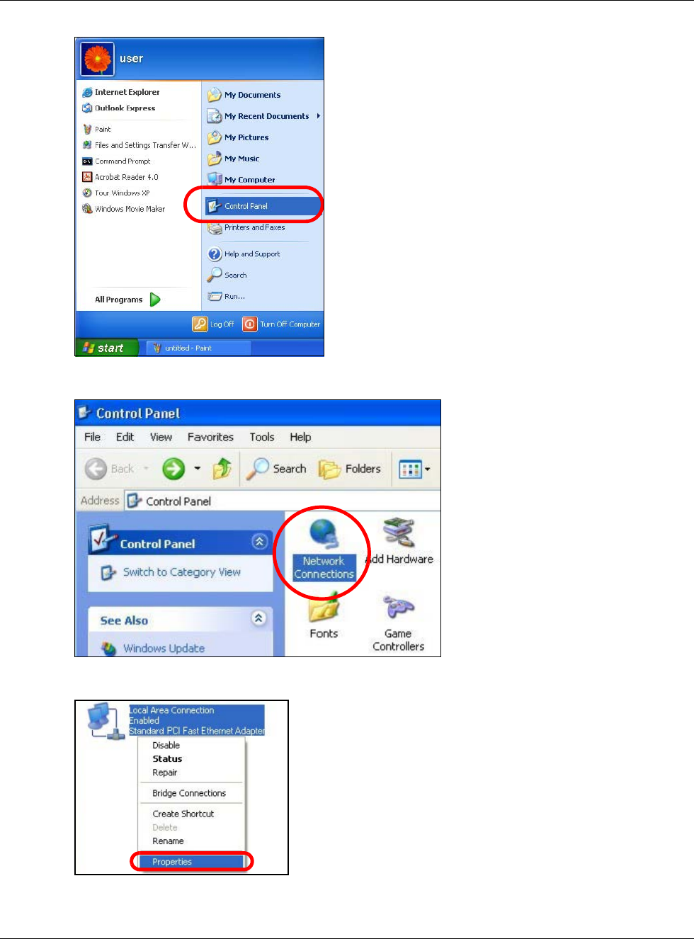
Appendix B Setting Up Your Computer’s IP Address
NBG6617 User’s Guide
163
2In the Control Panel, click the Network Connections icon.
3Right-click Local Area Connection and then select Properties.
4On the General tab, select Internet Protocol (TCP/IP) and then click Properties.
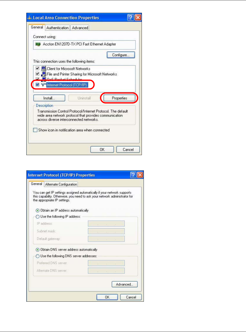
Appendix B Setting Up Your Computer’s IP Address
NBG6617 User’s Guide
164
5The Internet Protocol TCP/IP Properties window opens.
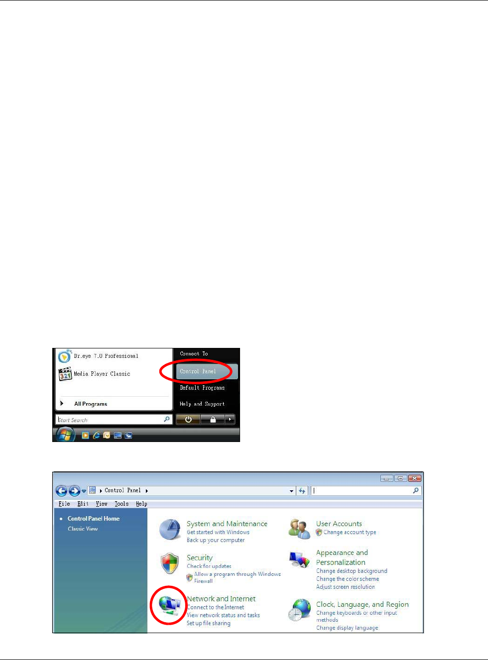
Appendix B Setting Up Your Computer’s IP Address
NBG6617 User’s Guide
165
6Select Obtain an IP address automatically if your network administrator or ISP assigns your IP
address dynamically.
Select Use the following IP Address and fill in the IP address, Subnet mask, and Default
gateway fields if you have a static IP address that was assigned to you by your network
administrator or ISP. You may also have to enter a Preferred DNS server and an Alternate DNS
server, if that information was provided.
7Click OK to close the Internet Protocol (TCP/IP) Properties window.
8Click OK to close the Local Area Connection Properties window.
Verifying Settings
1Click Start > All Programs > Accessories > Command Prompt.
2In the Command Prompt window, type "ipconfig" and then press [ENTER].
You can also go to Start > Control Panel > Network Connections, right-click a network
connection, click Status and then click the Support tab to view your IP address and connection
information.
Windows Vista
This section shows screens from Windows Vista Professional.
1Click Start > Control Panel.
2In the Control Panel, click the Network and Internet icon.
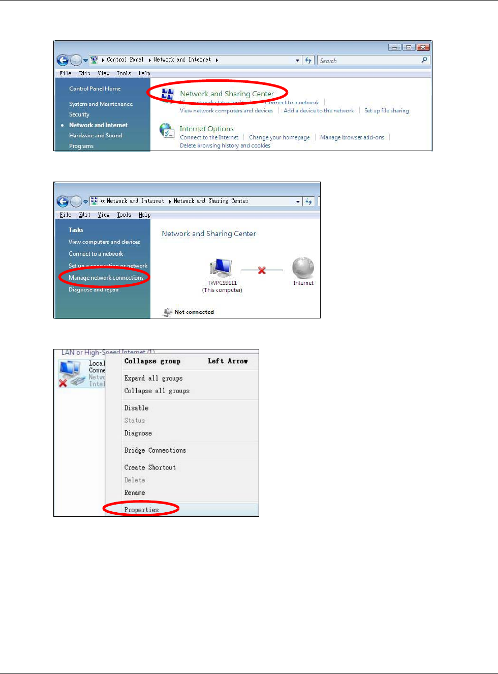
Appendix B Setting Up Your Computer’s IP Address
NBG6617 User’s Guide
166
3Click the Network and Sharing Center icon.
4Click Manage network connections.
5Right-click Local Area Connection and then select Properties.
Note: During this procedure, click Continue whenever Windows displays a screen saying
that it needs your permission to continue.
6Select Internet Protocol Version 4 (TCP/IPv4) and then select Properties.
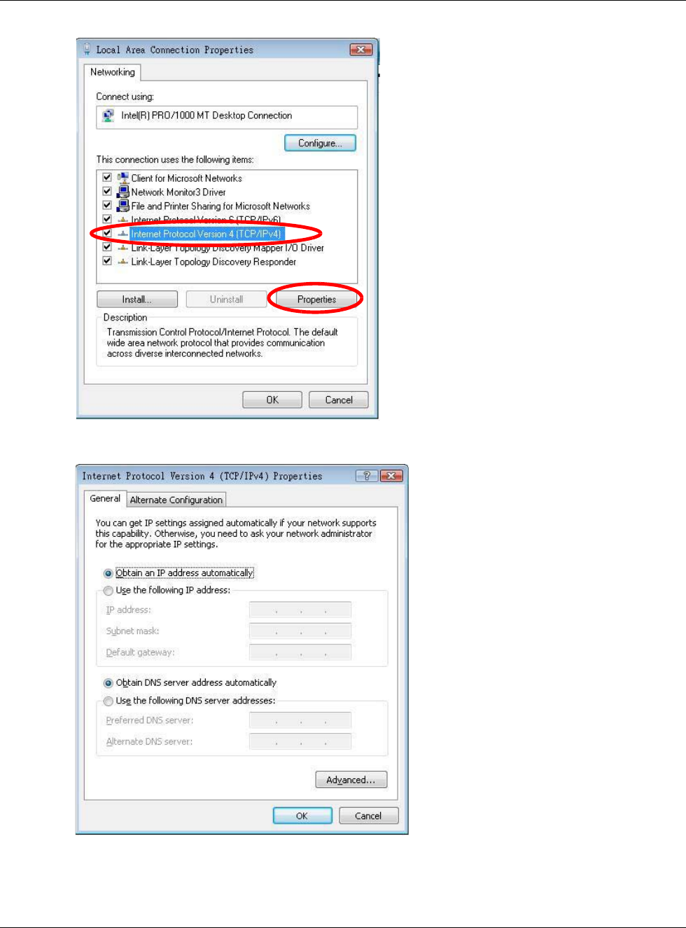
Appendix B Setting Up Your Computer’s IP Address
NBG6617 User’s Guide
167
7The Internet Protocol Version 4 (TCP/IPv4) Properties window opens.
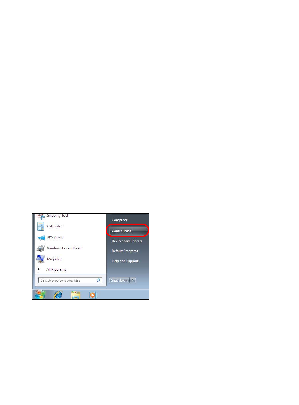
Appendix B Setting Up Your Computer’s IP Address
NBG6617 User’s Guide
168
8Select Obtain an IP address automatically if your network administrator or ISP assigns your IP
address dynamically.
Select Use the following IP Address and fill in the IP address, Subnet mask, and Default
gateway fields if you have a static IP address that was assigned to you by your network
administrator or ISP. You may also have to enter a Preferred DNS server and an Alternate DNS
server, if that information was provided.Click Advanced.
9Click OK to close the Internet Protocol (TCP/IP) Properties window.
10 Click OK to close the Local Area Connection Properties window.
Verifying Settings
1Click Start > All Programs > Accessories > Command Prompt.
2In the Command Prompt window, type "ipconfig" and then press [ENTER].
You can also go to Start > Control Panel > Network Connections, right-click a network
connection, click Status and then click the Support tab to view your IP address and connection
information.
Windows 7
This section shows screens from Windows 7 Enterprise.
1Click Start > Control Panel.
2In the Control Panel, click View network status and tasks under the Network and Internet
category.
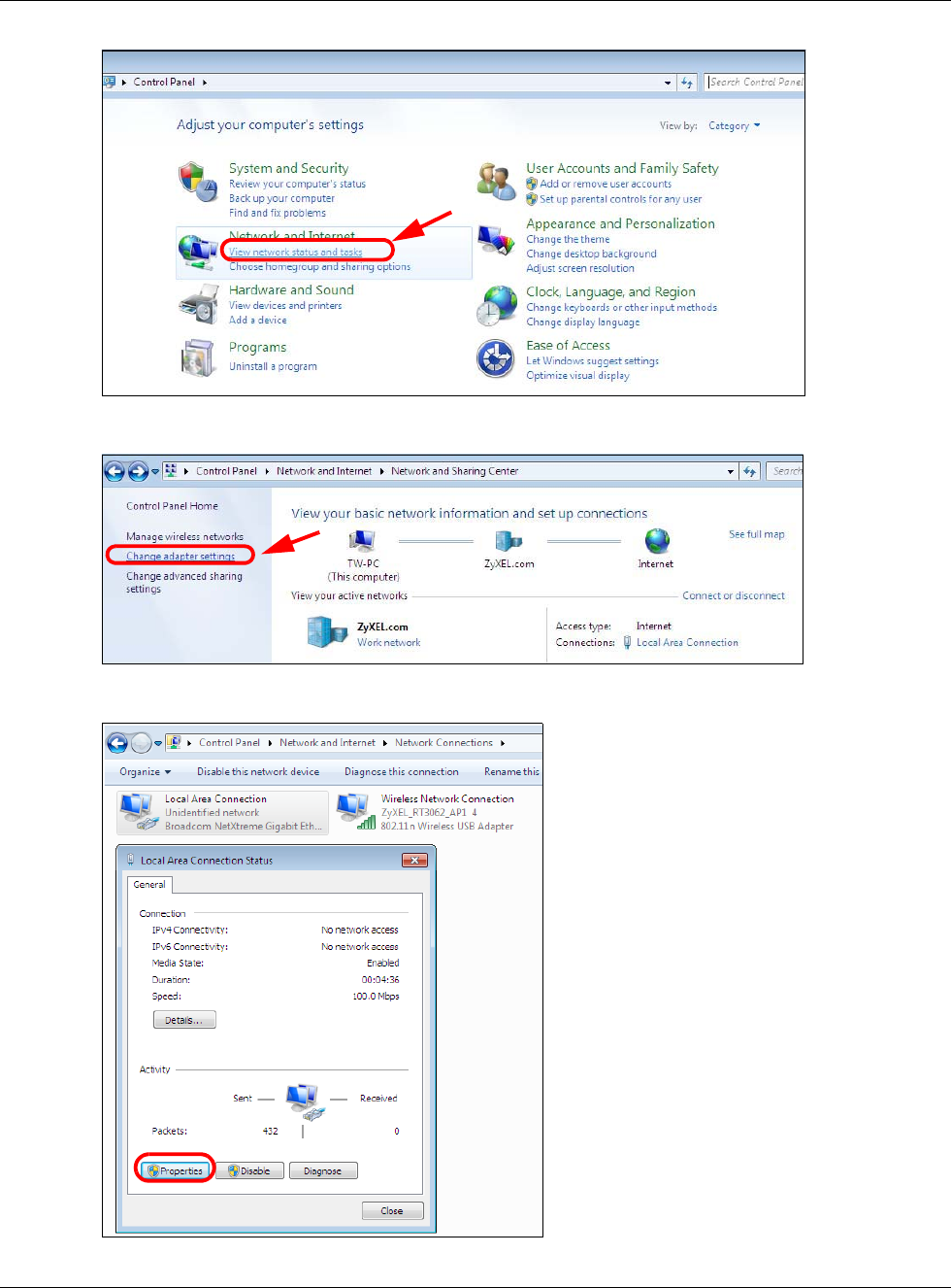
Appendix B Setting Up Your Computer’s IP Address
NBG6617 User’s Guide
169
3Click Change adapter settings.
4Double click Local Area Connection and then select Properties.
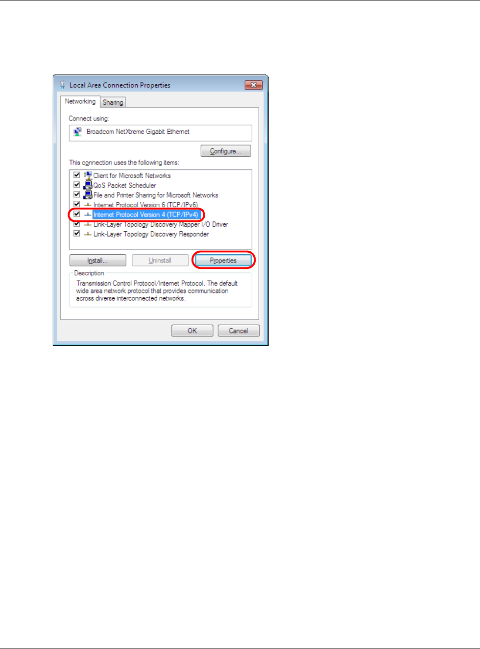
Appendix B Setting Up Your Computer’s IP Address
NBG6617 User’s Guide
170
Note: During this procedure, click Continue whenever Windows displays a screen saying
that it needs your permission to continue.
5Select Internet Protocol Version 4 (TCP/IPv4) and then select Properties.
6The Internet Protocol Version 4 (TCP/IPv4) Properties window opens.
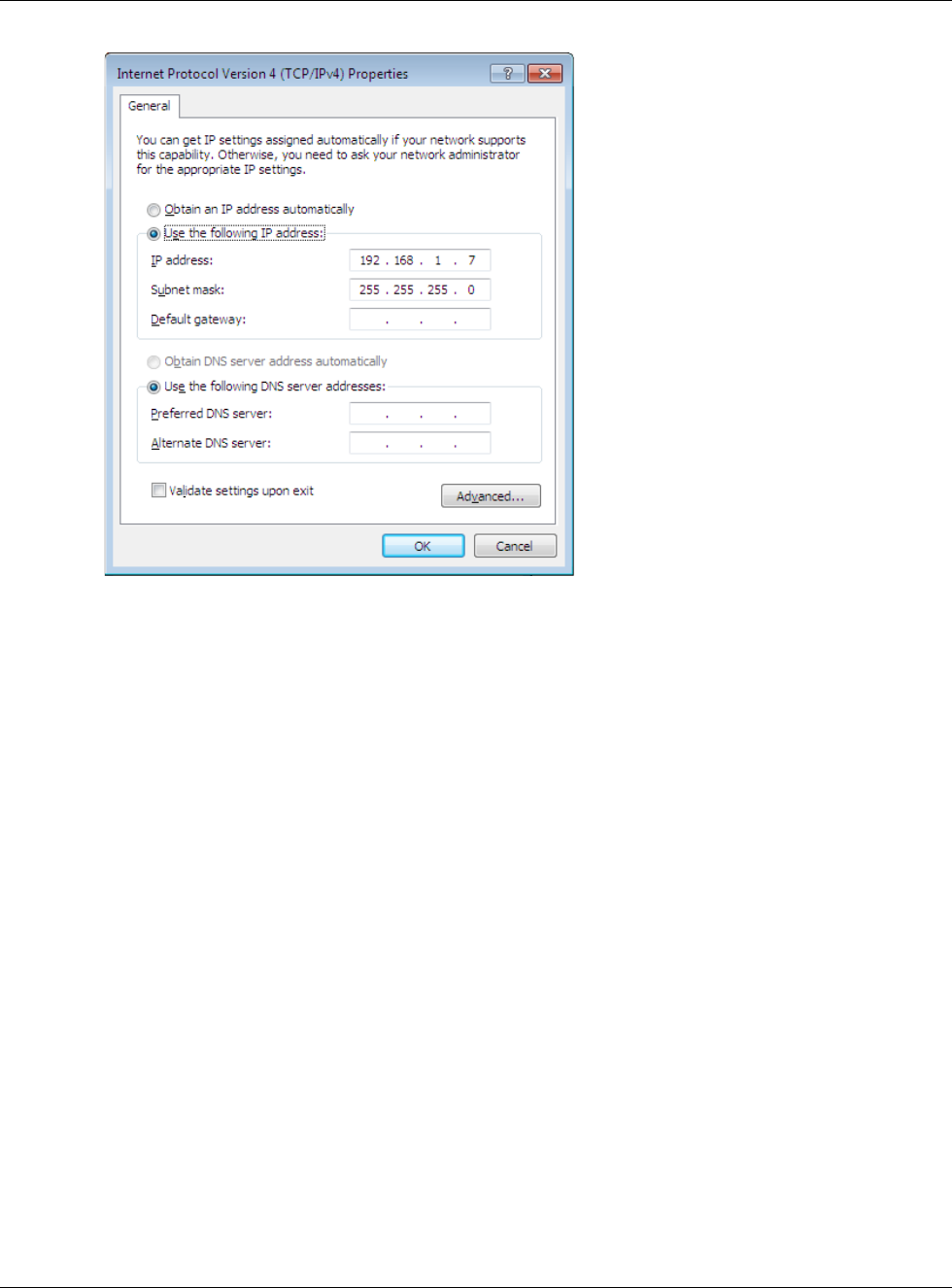
Appendix B Setting Up Your Computer’s IP Address
NBG6617 User’s Guide
171
7Select Obtain an IP address automatically if your network administrator or ISP assigns your IP
address dynamically.
Select Use the following IP Address and fill in the IP address, Subnet mask, and Default
gateway fields if you have a static IP address that was assigned to you by your network
administrator or ISP. You may also have to enter a Preferred DNS server and an Alternate DNS
server, if that information was provided. Click Advanced if you want to configure advanced
settings for IP, DNS and WINS.
8Click OK to close the Internet Protocol (TCP/IP) Properties window.
9Click OK to close the Local Area Connection Properties window.
Verifying Settings
1Click Start > All Programs > Accessories > Command Prompt.
2In the Command Prompt window, type "ipconfig" and then press [ENTER].
3The IP settings are displayed as follows.
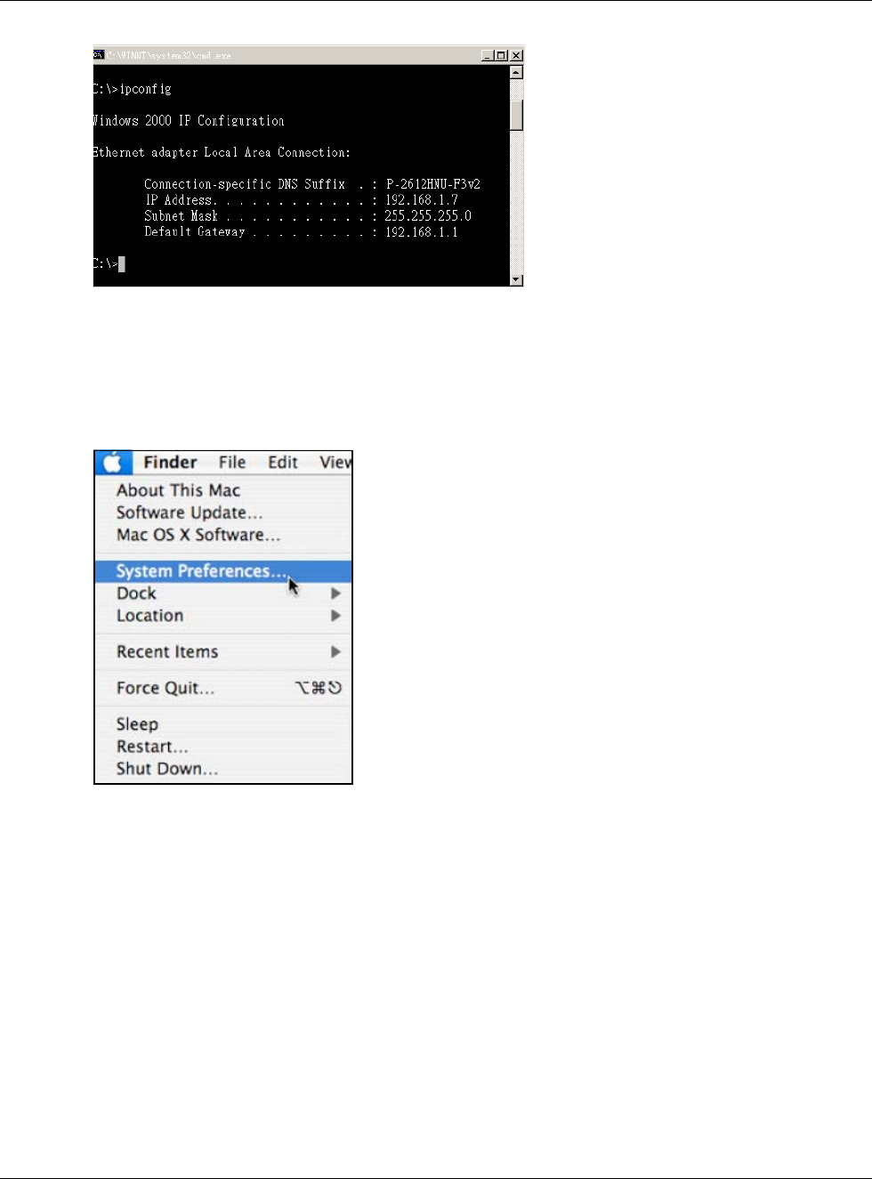
Appendix B Setting Up Your Computer’s IP Address
NBG6617 User’s Guide
172
Mac OS X: 10.3 and 10.4
The screens in this section are from Mac OS X 10.4 but can also apply to 10.3.
1Click Apple > System Preferences.
2In the System Preferences window, click the Network icon.
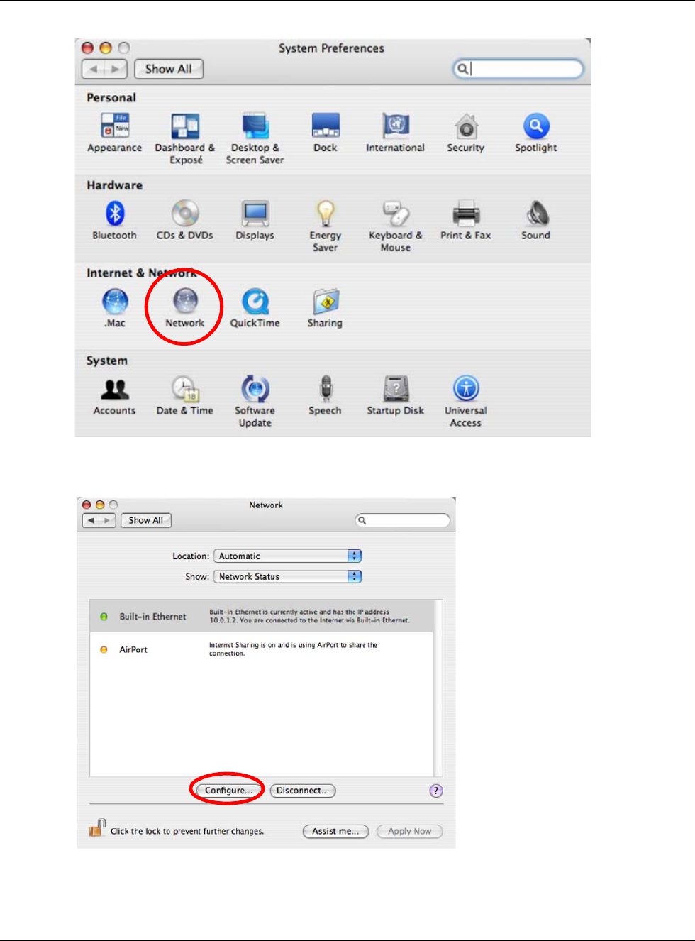
Appendix B Setting Up Your Computer’s IP Address
NBG6617 User’s Guide
173
3When the Network preferences pane opens, select Built-in Ethernet from the network
connection type list, and then click Configure.
4For dynamically assigned settings, select Using DHCP from the Configure IPv4 list in the TCP/IP
tab.
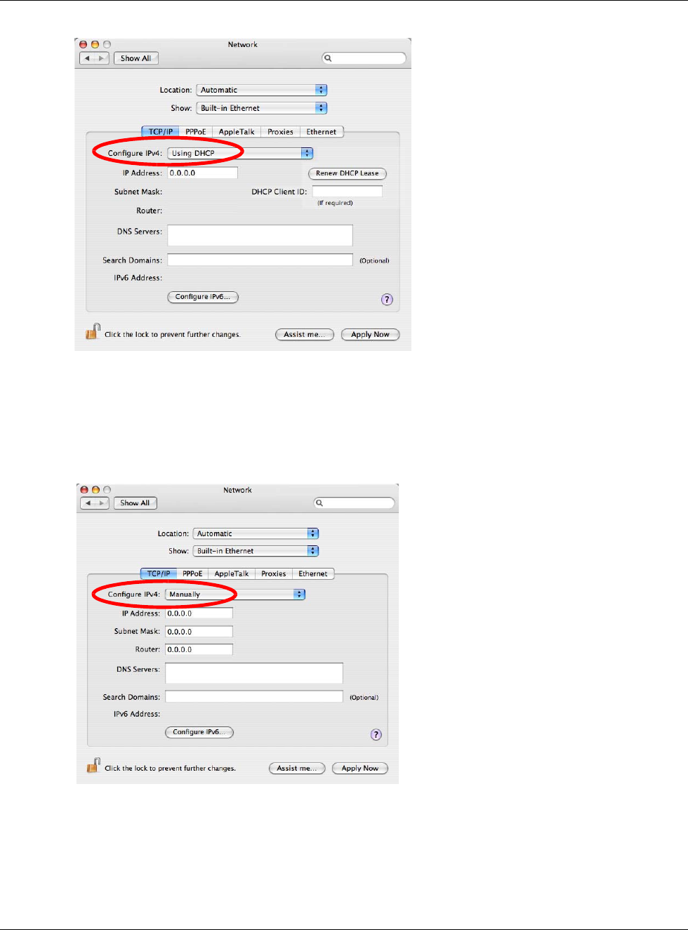
Appendix B Setting Up Your Computer’s IP Address
NBG6617 User’s Guide
174
5For statically assigned settings, do the following:
• From the Configure IPv4 list, select Manually.
•In the IP Address field, type your IP address.
•In the Subnet Mask field, type your subnet mask.
•In the Router field, type the IP address of your device.
6Click Apply Now and close the window.
Verifying Settings
Check your TCP/IP properties by clicking Applications > Utilities > Network Utilities, and then
selecting the appropriate Network Interface from the Info tab.
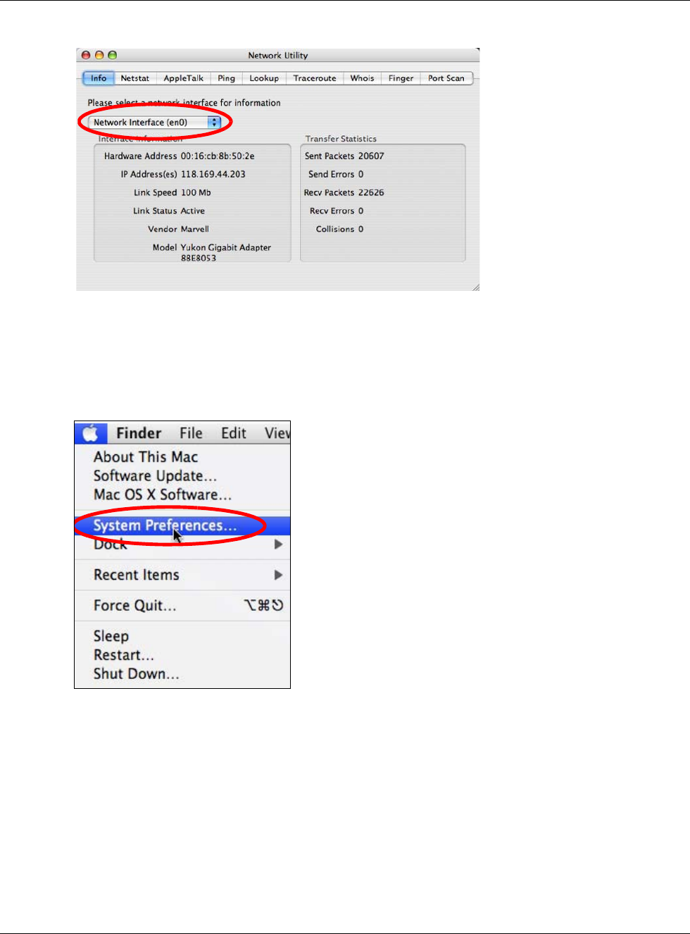
Appendix B Setting Up Your Computer’s IP Address
NBG6617 User’s Guide
175
Figure 101 Mac OS X 10.4: Network Utility
Mac OS X: 10.5 and 10.6
The screens in this section are from Mac OS X 10.5 but can also apply to 10.6.
1Click Apple > System Preferences.
2In System Preferences, click the Network icon.
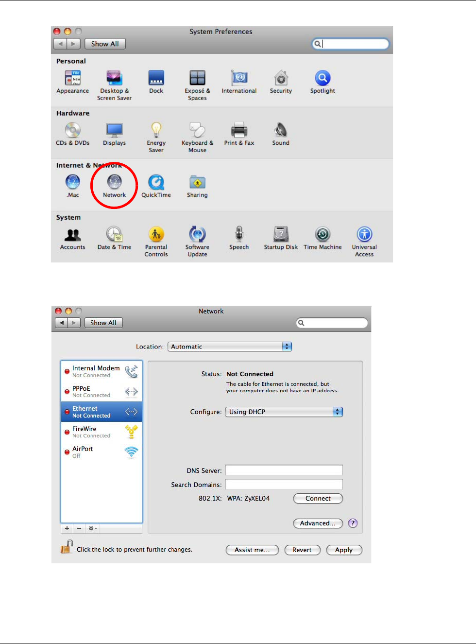
Appendix B Setting Up Your Computer’s IP Address
NBG6617 User’s Guide
176
3When the Network preferences pane opens, select Ethernet from the list of available connection
types.
4From the Configure list, select Using DHCP for dynamically assigned settings.
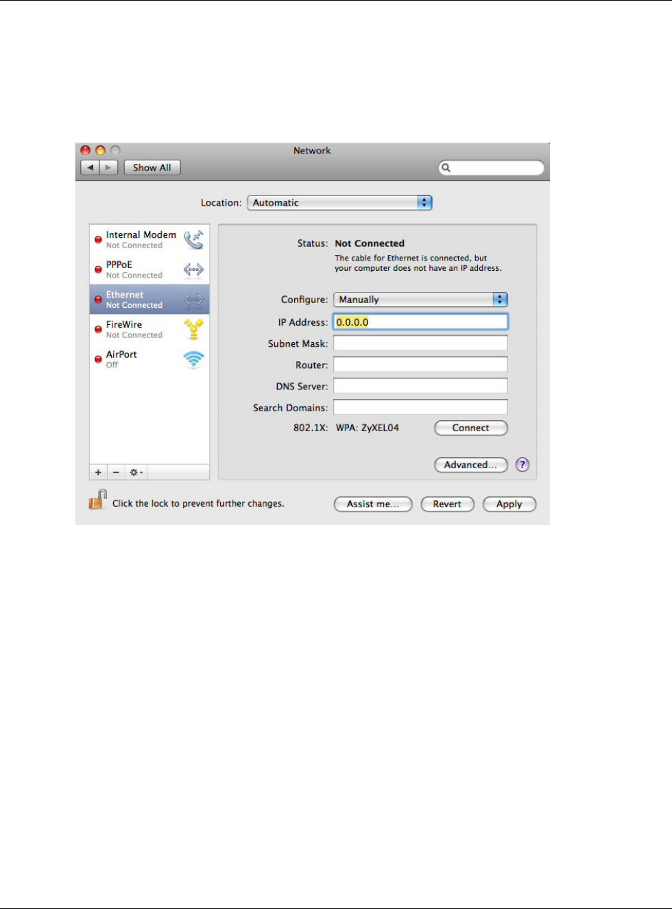
Appendix B Setting Up Your Computer’s IP Address
NBG6617 User’s Guide
177
5For statically assigned settings, do the following:
• From the Configure list, select Manually.
•In the IP Address field, enter your IP address.
•In the Subnet Mask field, enter your subnet mask.
•In the Router field, enter the IP address of your NBG6617.
6Click Apply and close the window.
Verifying Settings
Check your TCP/IP properties by clicking Applications > Utilities > Network Utilities, and then
selecting the appropriate Network interface from the Info tab.
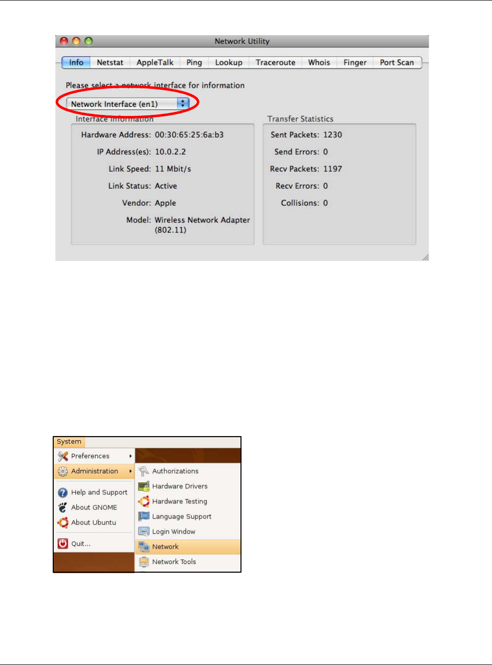
Appendix B Setting Up Your Computer’s IP Address
NBG6617 User’s Guide
178
Figure 102 Mac OS X 10.5: Network Utility
Linux: Ubuntu 8 (GNOME)
This section shows you how to configure your computer’s TCP/IP settings in the GNU Object Model
Environment (GNOME) using the Ubuntu 8 Linux distribution. The procedure, screens and file
locations may vary depending on your specific distribution, release version, and individual
configuration. The following screens use the default Ubuntu 8 installation.
Note: Make sure you are logged in as the root administrator.
Follow the steps below to configure your computer IP address in GNOME:
1Click System > Administration > Network.
2When the Network Settings window opens, click Unlock to open the Authenticate window. (By
default, the Unlock button is greyed out until clicked.) You cannot make changes to your
configuration unless you first enter your admin password.
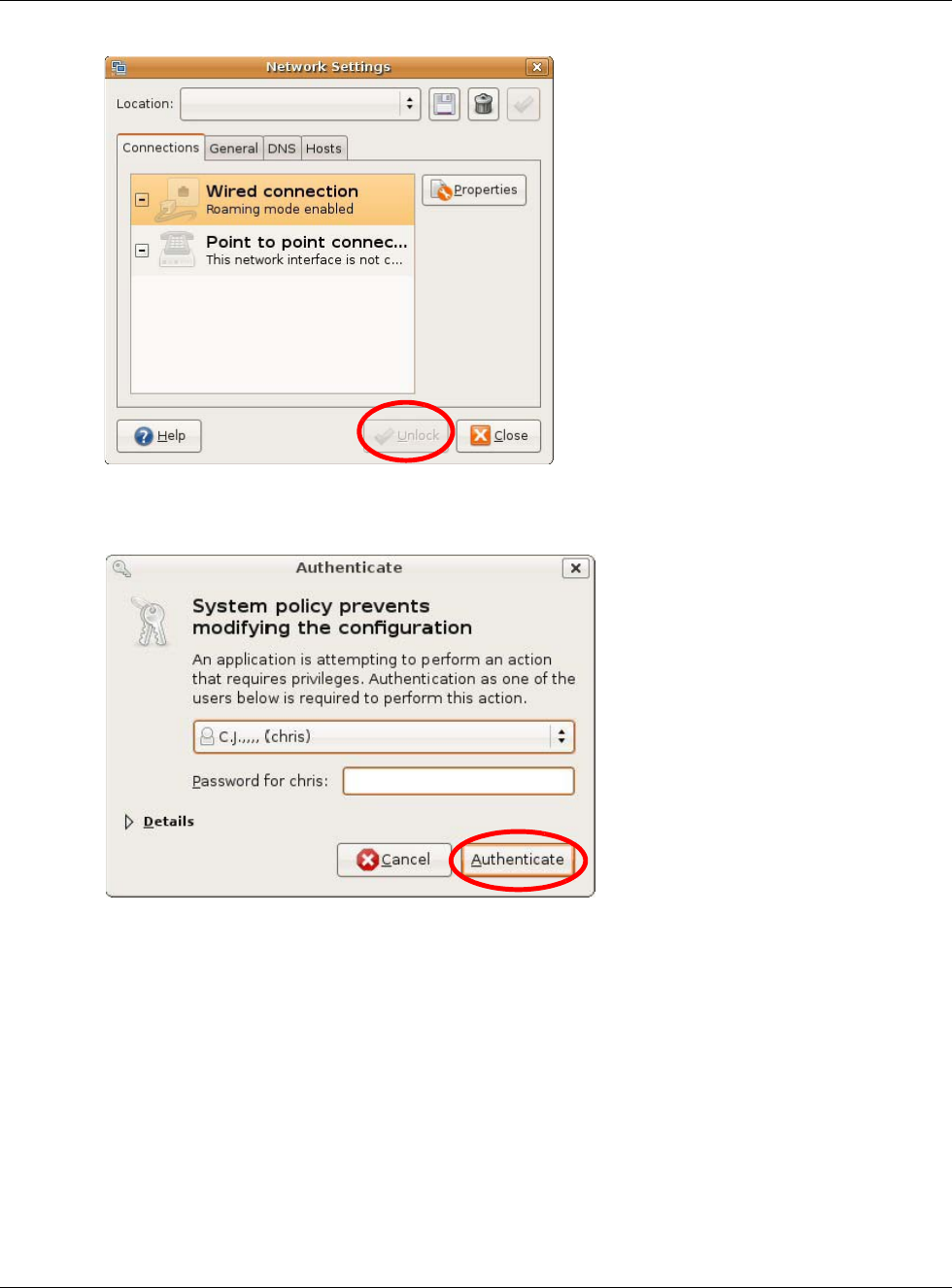
Appendix B Setting Up Your Computer’s IP Address
NBG6617 User’s Guide
179
3In the Authenticate window, enter your admin account name and password then click the
Authenticate button.
4In the Network Settings window, select the connection that you want to configure, then click
Properties.
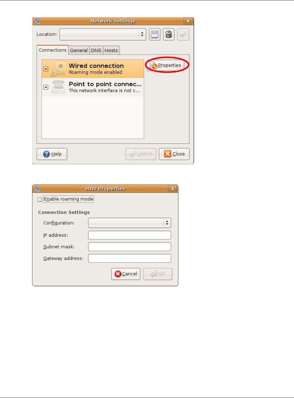
Appendix B Setting Up Your Computer’s IP Address
NBG6617 User’s Guide
180
5The Properties dialog box opens.
•In the Configuration list, select Automatic Configuration (DHCP) if you have a dynamic IP
address.
•In the Configuration list, select Static IP address if you have a static IP address. Fill in the
IP address, Subnet mask, and Gateway address fields.
6Click OK to save the changes and close the Properties dialog box and return to the Network
Settings screen.
7If you know your DNS server IP address(es), click the DNS tab in the Network Settings window
and then enter the DNS server information in the fields provided.
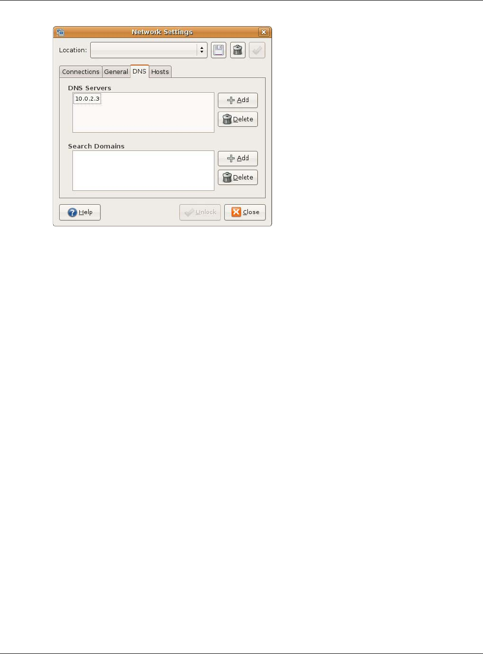
Appendix B Setting Up Your Computer’s IP Address
NBG6617 User’s Guide
181
8Click the Close button to apply the changes.
Verifying Settings
Check your TCP/IP properties by clicking System > Administration > Network Tools, and then
selecting the appropriate Network device from the Devices tab. The Interface Statistics
column shows data if your connection is working properly.
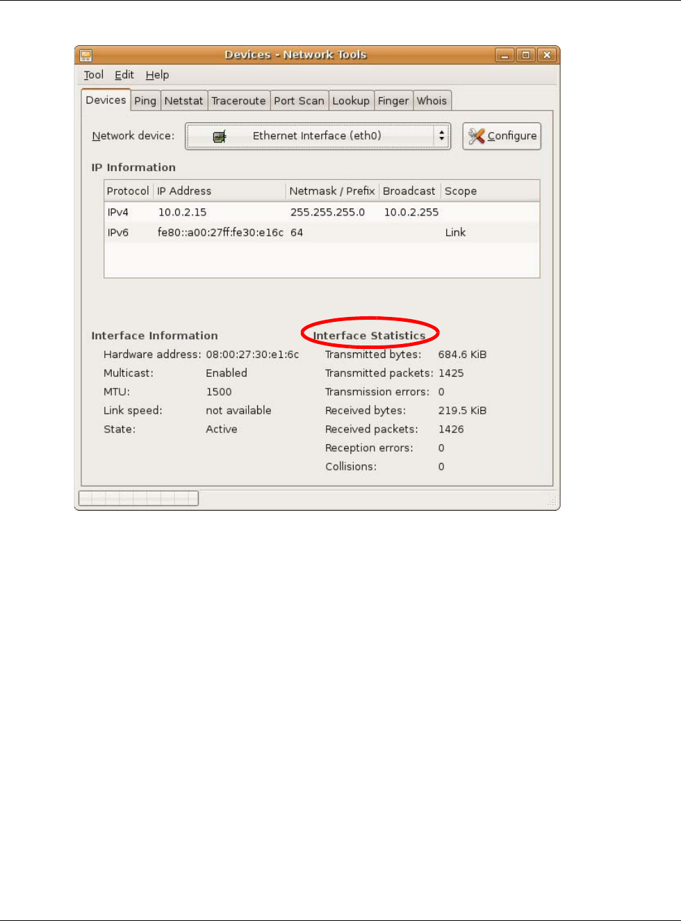
Appendix B Setting Up Your Computer’s IP Address
NBG6617 User’s Guide
182
Figure 103 Ubuntu 8: Network Tools
Linux: openSUSE 10.3 (KDE)
This section shows you how to configure your computer’s TCP/IP settings in the K Desktop
Environment (KDE) using the openSUSE 10.3 Linux distribution. The procedure, screens and file
locations may vary depending on your specific distribution, release version, and individual
configuration. The following screens use the default openSUSE 10.3 installation.
Note: Make sure you are logged in as the root administrator.
Follow the steps below to configure your computer IP address in the KDE:
1Click K Menu > Computer > Administrator Settings (YaST).
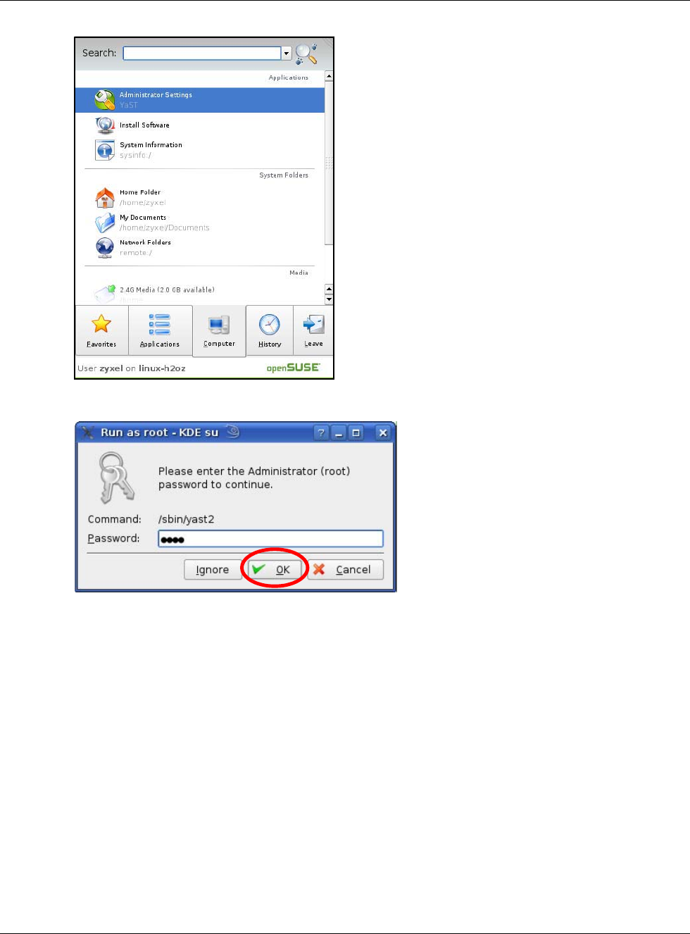
Appendix B Setting Up Your Computer’s IP Address
NBG6617 User’s Guide
183
2When the Run as Root - KDE su dialog opens, enter the admin password and click OK.
3When the YaST Control Center window opens, select Network Devices and then click the
Network Card icon.
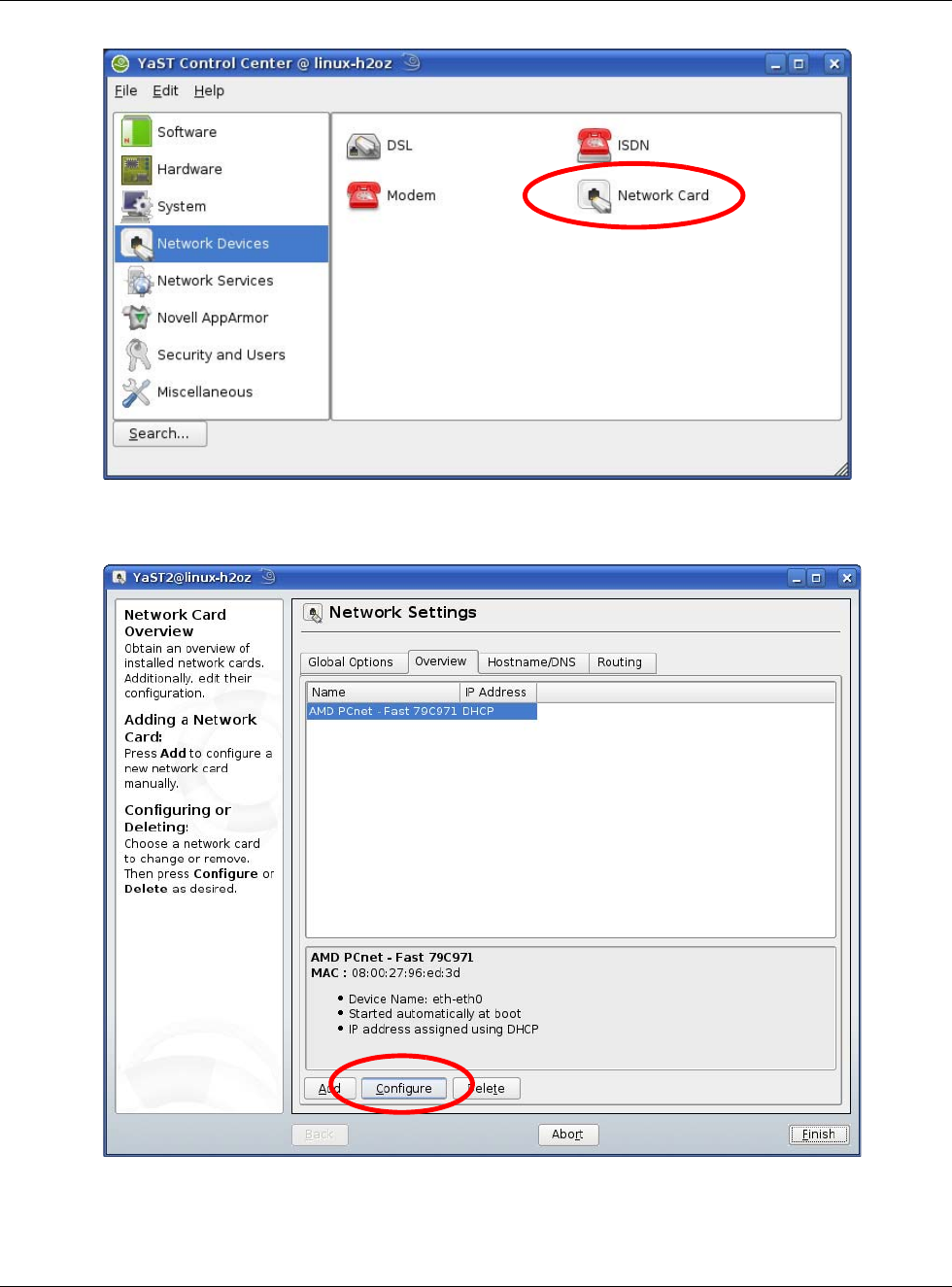
Appendix B Setting Up Your Computer’s IP Address
NBG6617 User’s Guide
184
4When the Network Settings window opens, click the Overview tab, select the appropriate
connection Name from the list, and then click the Configure button.
5When the Network Card Setup window opens, click the Address tab
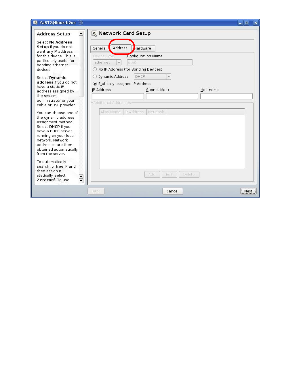
Appendix B Setting Up Your Computer’s IP Address
NBG6617 User’s Guide
185
Figure 104 openSUSE 10.3: Network Card Setup
6Select Dynamic Address (DHCP) if you have a dynamic IP address.
Select Statically assigned IP Address if you have a static IP address. Fill in the IP address,
Subnet mask, and Hostname fields.
7Click Next to save the changes and close the Network Card Setup window.
8If you know your DNS server IP address(es), click the Hostname/DNS tab in Network Settings
and then enter the DNS server information in the fields provided.
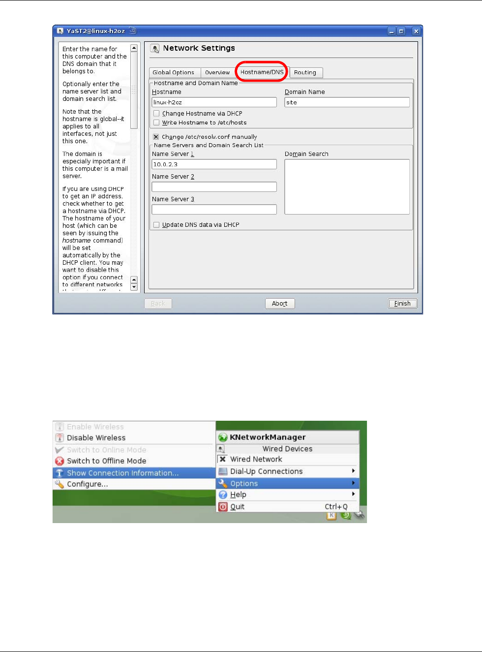
Appendix B Setting Up Your Computer’s IP Address
NBG6617 User’s Guide
186
9Click Finish to save your settings and close the window.
Verifying Settings
Click the KNetwork Manager icon on the Task bar to check your TCP/IP properties. From the
Options sub-menu, select Show Connection Information.
Figure 105 openSUSE 10.3: KNetwork Manager
When the Connection Status - KNetwork Manager window opens, click the Statistics tab to
see if your connection is working properly.
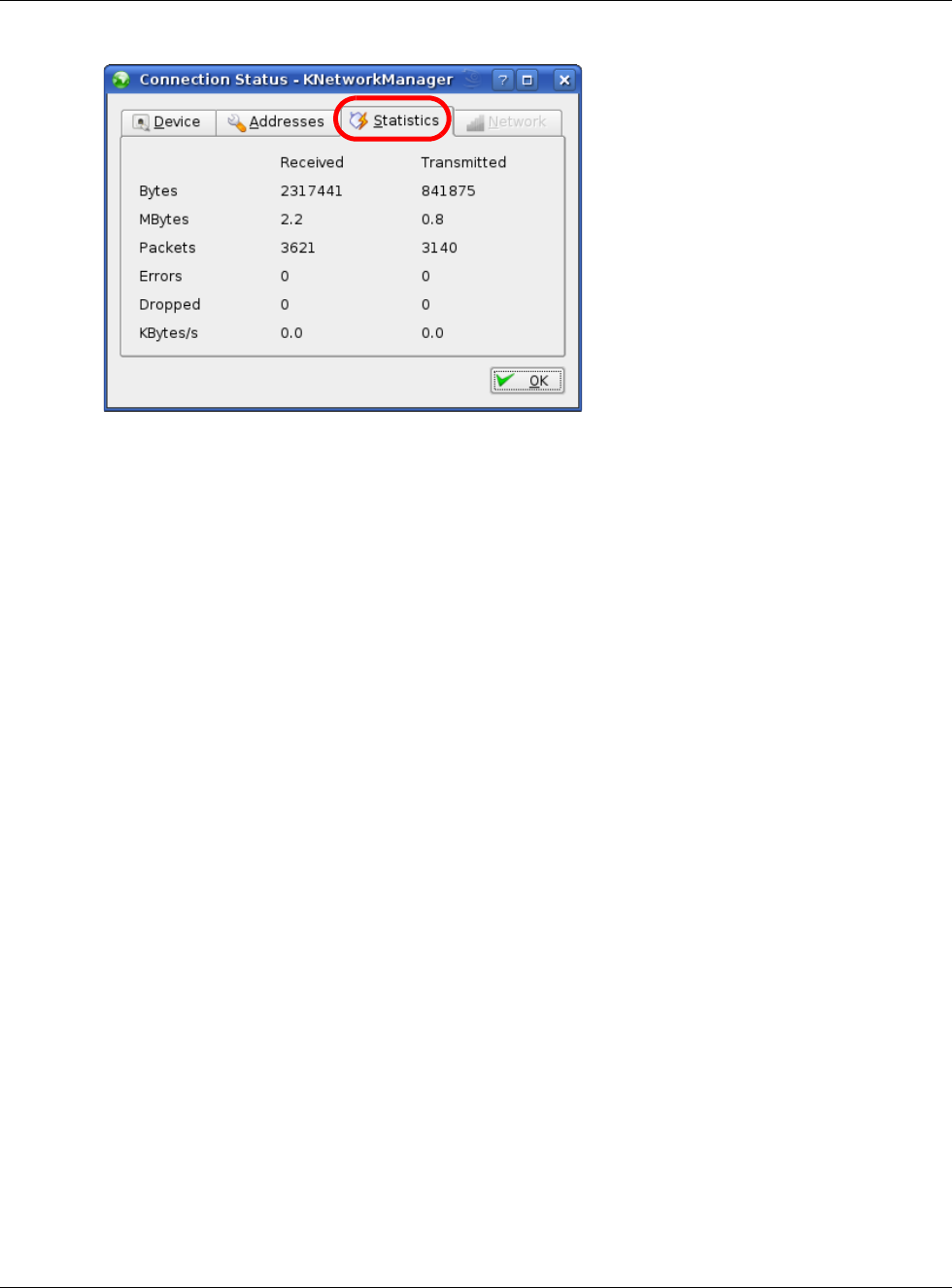
Appendix B Setting Up Your Computer’s IP Address
NBG6617 User’s Guide
187
Figure 106 openSUSE: Connection Status - KNetwork Manager

NBG6617 User’s Guide
188
APPENDIX C
Common Services
The following table lists some commonly-used services and their associated protocols and port
numbers. For a comprehensive list of port numbers, ICMP type/code numbers and services, visit
the IANA (Internet Assigned Number Authority) web site.
•Name: This is a short, descriptive name for the service. You can use this one or create a
different one, if you like.
•Protocol: This is the type of IP protocol used by the service. If this is TCP/UDP, then the service
uses the same port number with TCP and UDP. If this is USER-DEFINED, the Port(s) is the IP
protocol number, not the port number.
•Port(s): This value depends on the Protocol. Please refer to RFC 1700 for further information
about port numbers.
•If the Protocol is TCP, UDP, or TCP/UDP, this is the IP port number.
•If the Protocol is USER, this is the IP protocol number.
•Description: This is a brief explanation of the applications that use this service or the situations
in which this service is used.
Table 64 Commonly Used Services
NAME PROTOCOL PORT(S) DESCRIPTION
AH
(IPSEC_TUNNEL)
User-Defined 51 The IPSEC AH (Authentication Header) tunneling
protocol uses this service.
AIM/New-ICQ TCP 5190 AOL’s Internet Messenger service. It is also used as
a listening port by ICQ.
AUTH TCP 113 Authentication protocol used by some servers.
BGP TCP 179 Border Gateway Protocol.
BOOTP_CLIENT UDP 68 DHCP Client.
BOOTP_SERVER UDP 67 DHCP Server.
CU-SEEME TCP
UDP
7648
24032
A popular videoconferencing solution from White
Pines Software.
DNS TCP/UDP 53 Domain Name Server, a service that matches web
names (for example www.zyxel.com) to IP
numbers.
ESP
(IPSEC_TUNNEL)
User-Defined 50 The IPSEC ESP (Encapsulation Security Protocol)
tunneling protocol uses this service.
FINGER TCP 79 Finger is a UNIX or Internet related command that
can be used to find out if a user is logged on.
FTP TCP
TCP
20
21
File Transfer Program, a program to enable fast
transfer of files, including large files that may not
be possible by e-mail.
H.323 TCP 1720 NetMeeting uses this protocol.
HTTP TCP 80 Hyper Text Transfer Protocol - a client/server
protocol for the world wide web.

Appendix C Common Services
NBG6617 User’s Guide
189
HTTPS TCP 443 HTTPS is a secured http session often used in e-
commerce.
ICMP User-Defined 1Internet Control Message Protocol is often used for
diagnostic or routing purposes.
ICQ UDP 4000 This is a popular Internet chat program.
IGMP (MULTICAST) User-Defined 2Internet Group Management Protocol is used when
sending packets to a specific group of hosts.
IKE UDP 500 The Internet Key Exchange algorithm is used for
key distribution and management.
IRC TCP/UDP 6667 This is another popular Internet chat program.
MSN Messenger TCP 1863 Microsoft Networks’ messenger service uses this
protocol.
NEW-ICQ TCP 5190 An Internet chat program.
NEWS TCP 144 A protocol for news groups.
NFS UDP 2049 Network File System - NFS is a client/server
distributed file service that provides transparent file
sharing for network environments.
NNTP TCP 119 Network News Transport Protocol is the delivery
mechanism for the USENET newsgroup service.
PING User-Defined 1Packet INternet Groper is a protocol that sends out
ICMP echo requests to test whether or not a remote
host is reachable.
POP3 TCP 110 Post Office Protocol version 3 lets a client computer
get e-mail from a POP3 server through a temporary
connection (TCP/IP or other).
PPTP TCP 1723 Point-to-Point Tunneling Protocol enables secure
transfer of data over public networks. This is the
control channel.
PPTP_TUNNEL
(GRE)
User-Defined 47 PPTP (Point-to-Point Tunneling Protocol) enables
secure transfer of data over public networks. This is
the data channel.
RCMD TCP 512 Remote Command Service.
REAL_AUDIO TCP 7070 A streaming audio service that enables real time
sound over the web.
REXEC TCP 514 Remote Execution Daemon.
RLOGIN TCP 513 Remote Login.
RTELNET TCP 107 Remote Telnet.
RTSP TCP/UDP 554 The Real Time Streaming (media control) Protocol
(RTSP) is a remote control for multimedia on the
Internet.
SFTP TCP 115 Simple File Transfer Protocol.
SMTP TCP 25 Simple Mail Transfer Protocol is the message-
exchange standard for the Internet. SMTP enables
you to move messages from one e-mail server to
another.
SNMP TCP/UDP 161 Simple Network Management Program.
SNMP-TRAPS TCP/UDP 162 Traps for use with the SNMP (RFC:1215).
Table 64 Commonly Used Services (continued)
NAME PROTOCOL PORT(S) DESCRIPTION

Appendix C Common Services
NBG6617 User’s Guide
190
SQL-NET TCP 1521 Structured Query Language is an interface to
access data on many different types of database
systems, including mainframes, midrange systems,
UNIX systems and network servers.
SSH TCP/UDP 22 Secure Shell Remote Login Program.
STRM WORKS UDP 1558 Stream Works Protocol.
SYSLOG UDP 514 Syslog allows you to send system logs to a UNIX
server.
TACACS UDP 49 Login Host Protocol used for (Terminal Access
Controller Access Control System).
TELNET TCP 23 Telnet is the login and terminal emulation protocol
common on the Internet and in UNIX environments.
It operates over TCP/IP networks. Its primary
function is to allow users to log into remote host
systems.
TFTP UDP 69 Trivial File Transfer Protocol is an Internet file
transfer protocol similar to FTP, but uses the UDP
(User Datagram Protocol) rather than TCP
(Transmission Control Protocol).
VDOLIVE TCP 7000 Another videoconferencing solution.
Table 64 Commonly Used Services (continued)
NAME PROTOCOL PORT(S) DESCRIPTION

NBG6617 User’s Guide
191
APPENDIX D
Legal Information
Copyright
Copyright © 2016 by ZyXEL Communications Corporation.
The contents of this publication may not be reproduced in any part or as a whole, transcribed, stored in a retrieval system, translated into
any language, or transmitted in any form or by any means, electronic, mechanical, magnetic, optical, chemical, photocopying, manual, or
otherwise, without the prior written permission of ZyXEL Communications Corporation.
Published by ZyXEL Communications Corporation. All rights reserved.
Disclaimer
ZyXEL does not assume any liability arising out of the application or use of any products, or software described herein. Neither does it
convey any license under its patent rights nor the patent rights of others. ZyXEL further reserves the right to make changes in any
products described herein without notice. This publication is subject to change without notice.
Regulatory Notice and Statement
UNITED STATES of AMERICA
The following information applies if you use the product within USA area.
FCC EMC Statement
• The device complies with Part 15 of FCC rules. Operation is subject to the following two conditions:
(1) This device may not cause harmful interference, and
(2) This device must accept any interference received, including interference that may cause undesired operation.
• Changes or modifications not expressly approved by the party responsible for compliance could void the user’s authority to operate the
device.
• This product has been tested and complies with the specifications for a Class B digital device, pursuant to Part 15 of the FCC Rules.
These limits are designed to provide reasonable protection against harmful interference in a residential installation. This device
generates, uses, and can radiate radio frequency energy and, if not installed and used according to the instructions, may cause
harmful interference to radio communications. However, there is no guarantee that interference will not occur in a particular
installation.
• If this device does cause harmful interference to radio or television reception, which is found by turning the device off and on, the user
is encouraged to try to correct the interference by one or more of the following measures:
•Reorient or relocate the receiving antenna
•Increase the separation between the devices
•Connect the equipment to an outlet other than the receiver’s
•Consult a dealer or an experienced radio/TV technician for assistance
FCC Radiation Exposure Statement
• This device complies with FCC RF radiation exposure limits set forth for an uncontrolled environment.
This transmitter must be at least 20 cm from the user and must not be co-located or operating in conjunction with any other antenna or
transmitter.
CANADA
The following information applies if you use the product within Canada area
Industry Canada ICES statement
CAN ICES-3 (B)/NMB-3(B)
For operation within 5.15 ~ 5.25GHz frequency range, it is restricted to indoor environment.

Appendix D Legal Information
NBG6617 User’s Guide
192
Industry Canada RSS-GEN & RSS-247 statement
• This device complies with Industry Canada license-exempt RSS standard(s). Operation is subject to the following two conditions: (1)
this device may not cause interference, and (2) this device must accept any interference, including interference that may cause
undesired operation of the device.
• This radio transmitter (2468C-NBG6617) has been approved by Industry Canada to operate with the antenna types listed below with
the maximum permissible gain and required antenna impedance for each antenna type indicated. Antenna types not included in this
list, having a gain greater than the maximum gain indicated for that type, are strictly prohibited for use with this device.
Antenna Information (For External Antenna)
If the product with 5G wireless function operating in 5150-5250 MHz and 5725-5850 MHz , the following attention must be paid,
• The device for operation in the band 5150-5250 MHz is only for indoor use to reduce the potential for harmful interference to co-
channel mobile satellite systems.
• For devices with detachable antenna(s), the maximum antenna gain permitted for devices in the band 5725-5850 MHz shall be such
that the equipment still complies with the e.i.r.p. limits specified for point-to-point and non-point-to-point operation as appropriate;
and
• The worst-case tilt angle(s) necessary to remain compliant with the e.i.r.p. elevation mask requirement set forth in Section 6.2.2(3) of
RSS 247 shall be clearly indicated.
If the product with 5G wireless function operating in 5250-5350 MHz and 5470-5725 MHz , the following attention must be paid.
• For devices with detachable antenna(s), the maximum antenna gain permitted for devices in the bands 5250-5350 MHz and 5470-
5725 MHz shall be such that the equipment still complies with the e.i.r.p. limit
• Le présent appareil est conforme aux CNR d’Industrie Canada applicables aux appareils radio exempts de licence. L’exploitation est
autorisée aux deux conditions suivantes : (1) l’appareil ne doit pas produire de brouillage, et (2) l’utilisateur de l’appareil doit accepter
tout brouillage radioélectrique subi, même si le brouillage est susceptible d’en compromettre le fonctionnement.
• Le présent émetteur radio (2468C-NBG6617) de modèle s'il fait partie du matériel de catégorieI) a été approuvé par Industrie Canada
pour fonctionner avec les types d'antenne énumérés ci-dessous et ayant un gain admissible maximal et l'impédance requise pour
chaque type d'antenne. Les types d'antenne non inclus dans cette liste, ou dont le gain est supérieur au gain maximal indiqué, sont
strictement interdits pour l'exploitation de l'émetteur.
Informations Antenne (For External Antenna)
Lorsque la fonction sans fil 5G fonctionnant en5150-5250 MHz and 5725-5850 MHz est activée pour ce produit , il est nécessaire de porter
une attention particulière aux choses suivantes
• Les dispositifs fonctionnant dans la bande 5150-5250 MHz sont réservés uniquement pour une utilisation à l’intérieur afin de réduire
les risques de brouillage préjudiciable aux systèmes de satellites mobiles utilisant les mêmes canaux;
• Pour les dispositifs munis d’antennes amovibles, le gain maximal d'antenne permis (pour les dispositifs utilisant la bande de 5 725 à 5
850 MHz) doit être conforme à la limite de la p.i.r.e. spécifiée pour l'exploitation point à point et l’exploitation non point à point, selon
le cas;
• Les pires angles d’inclinaison nécessaires pour rester conforme à l’exigence de la p.i.r.e. applicable au masque d’élévation, et énoncée
à la section 6.2.2 3) du CNR-247, doivent être clairement indiqués.
Lorsque la fonction sans fil 5G fonctionnant en 5250-5350 MHz et 5470-5725 MHz est activée pour ce produit , il est nécessaire de
porter une attention particulière aux choses suivantes
• Pour les dispositifs munis d’antennes amovibles, le gain maximal d'antenne permis pour les dispositifs utilisant les bandes de 5 250 à
5 350 MHz et de 5 470 à 5 725 MHz doit être conforme à la limite de la p.i.r.e.
TYPE MANUFACTURER GAIN CONNECTOR
Dipole 1 Aristotle 1.44dBi
(2400-2500MHz)
0.37dBi
(5260-5320MHz)
UFL
Dipole 2 Aristotle 1.78dBi
(2400-2500MHz)
3.23dBi
(5745-5825MHz)
UFL
TYPE FABRICANT GAIN CONNECTEUR
Dipole 1 Aristotle 1.44dBi
(2400-2500MHz)
0.37dBi
(5260-5320MHz)
UFL
Dipole 2 Aristotle 1.78dBi
(2400-2500MHz)
3.23dBi
(5745-5825MHz)
UFL

Appendix D Legal Information
NBG6617 User’s Guide
193
Industry Canada radiation exposure statement
This device complies with IC radiation exposure limits set forth for an uncontrolled environment. This device should be installed and
operated with a minimum distance of 20 cm between the radiator and your body.
Déclaration d’exposition aux radiations:
Cet équipement est conforme aux limites d’exposition aux rayonnements IC établies pour un environnement non contrôlé. Cet
équipement doit être installé et utilisé avec un minimum de 20 cm de distance entre la source de rayonnement et votre corps.
EUROPEAN UNION
The following information applies if you use the product within the European Union.
Declaration of Conformity with Regard to EU Directive 1999/5/EC (R&TTE Directive)
Compliance information for 2.4GHz and/or 5GHz wireless products relevant to the EU and other Countries following the EU Directive 1999/
5/EC (R&TTE)
(Bulgarian) ZyXEL ,
1999/5/C.
Español
(Spanish) Por medio de la presente ZyXEL declara que el equipo cumple con los requisitos esenciales y cualesquiera otras
disposiciones aplicables o exigibles de la Directiva 1999/5/CE.
eština
(Czech) ZyXEL tímto prohlašuje, že tento zaízení je ve shod se základními požadavky a dalšími píslušnými ustanoveními
smrnice 1999/5/EC.
Dansk (Danish) Undertegnede ZyXEL erklærer herved, at følgende udstyr udstyr overholder de væsentlige krav og øvrige relevante
krav i direktiv 1999/5/EF.
Deutsch
(German) Hiermit erklärt ZyXEL, dass sich das Gerät Ausstattung in Übereinstimmung mit den grundlegenden Anforderungen
und den übrigen einschlägigen Bestimmungen der Richtlinie 1999/5/EU befindet.
Eesti keel
(Estonian) Käesolevaga kinnitab ZyXEL seadme seadmed vastavust direktiivi 1999/5/EÜ põhinõuetele ja nimetatud direktiivist
tulenevatele teistele asjakohastele sätetele.
(Greek) ZyXEL
1999/5/C.
English Hereby, ZyXEL declares that this device is in compliance with the essential requirements and other relevant provisions
of Directive 1999/5/EC.
Français
(French) Par la présente ZyXEL déclare que l'appareil équipements est conforme aux exigences essentielles et aux autres
dispositions pertinentes de la directive 1999/5/EC.
Hrvatski
(Croatian) ZyXEL ovime izjavljuje da je radijska oprema tipa u skladu s Direktivom 1999/5/EC.
Íslenska
(Icelandic) Hér með lýsir, ZyXEL því yfir að þessi búnaður er í samræmi við grunnkröfur og önnur viðeigandi ákvæði tilskipunar
1999/5/EC.
Italiano
(Italian) Con la presente ZyXEL dichiara che questo attrezzatura è conforme ai requisiti essenziali ed alle altre disposizioni
pertinenti stabilite dalla direttiva 1999/5/CE.
Latviešu valoda
(Latvian) Ar šo ZyXEL deklar, ka iekrtas atbilst Direktvas 1999/5/EK btiskajm prasbm un citiem ar to saisttajiem
noteikumiem.
Lietuvi kalba
(Lithuanian) Šiuo ZyXEL deklaruoja, kad šis ranga atitinka esminius reikalavimus ir kitas 1999/5/EB Direktyvos nuostatas.
Magyar
(Hungarian) Alulírott, ZyXEL nyilatkozom, hogy a berendezés megfelel a vonatkozó alapvetõ követelményeknek és az 1999/5/EK
irányelv egyéb elõírásainak.
Malti (Maltese) Hawnhekk, ZyXEL, jiddikjara li dan tagmir jikkonforma mal-tiijiet essenzjali u ma provvedimenti orajn relevanti li
hemm fid-Dirrettiva 1999/5/EC.
Nederlands
(Dutch) Hierbij verklaart ZyXEL dat het toestel uitrusting in overeenstemming is met de essentiële eisen en de andere
relevante bepalingen van richtlijn 1999/5/EC.
Polski (Polish) Niniejszym ZyXEL owiadcza, e sprzt jest zgodny z zasadniczymi wymogami oraz pozostaymi stosownymi
postanowieniami Dyrektywy 1999/5/EC.
Português
(Portuguese) ZyXEL declara que este equipamento está conforme com os requisitos essenciais e outras disposições da Directiva
1999/5/EC.
Român
(Romanian) Prin prezenta, ZyXEL declar c acest echipament este în conformitate cu cerinele eseniale i alte prevederi
relevante ale Directivei 1999/5/EC.

Appendix D Legal Information
NBG6617 User’s Guide
194
This device is restricted to indoor use only when operating in the 5150 to 5350 MHz frequency range.
National Restrictions
This product may be used in all EU countries (and other countries following the EU Directive 1999/5/EC) without any limitation except for
the countries mentioned below:
Ce produit peut être utilisé dans tous les pays de l’UE (et dans tous les pays ayant transposés la directive 1999/5/CE) sans aucune
limitation, excepté pour les pays mentionnés ci-dessous:
Questo prodotto è utilizzabile in tutte i paesi EU (ed in tutti gli altri paesi che seguono le direttiva 1999/5/EC) senza nessuna limitazione,
eccetto per i paesii menzionati di seguito:
Das Produkt kann in allen EU Staaten ohne Einschränkungen eingesetzt werden (sowie in anderen Staaten die der Richtlinie 1999/5/CE
folgen) mit Außnahme der folgenden aufgeführten Staaten:
In the majority of the EU and other European countries, the 2.4GHz and 5GHz bands have been made available for the use of wireless
local area networks (LANs). Later in this document you will find an overview of countries in which additional restrictions or requirements
or both are applicable.
The requirements for any country may evolve. ZyXEL recommends that you check with the local authorities for the latest status of their
national regulations for both the 2.4GHz and 5GHz wireless LANs.
The following countries have restrictions and/or requirements in addition to those given in the table labeled “Overview of Regulatory
Requirements for Wireless LANs”:.
Belgium
The Belgian Institute for Postal Services and Telecommunications (BIPT) must be notified of any outdoor wireless link having a range
exceeding 300 meters. Please check http://www.bipt.be for more details.
Draadloze verbindingen voor buitengebruik en met een reikwijdte van meer dan 300 meter dienen aangemeld te worden bij het Belgisch
Instituut voor postdiensten en telecommunicatie (BIPT). Zie http://www.bipt.be voor meer gegevens.
Les liaisons sans fil pour une utilisation en extérieur d’une distance supérieure à 300 mètres doivent être notifiées à l’Institut Belge des
services Postaux et des Télécommunications (IBPT). Visitez http://www.ibpt.be pour de plus amples détails.
Denmark
In Denmark, the band 5150 - 5350 MHz is also allowed for outdoor usage.
I Danmark må frekvensbåndet 5150 - 5350 også anvendes udendørs.
Italy
This product meets the National Radio Interface and the requirements specified in the National Frequency Allocation Table for Italy. Unless
this wireless LAN product is operating within the boundaries of the owner's property, its use requires a “general authorization.” Please
check http://www.sviluppoeconomico.gov.it/ for more details.
Questo prodotto è conforme alla specifiche di Interfaccia Radio Nazionali e rispetta il Piano Nazionale di ripartizione delle frequenze in
Italia. Se non viene installato all 'interno del proprio fondo, l'utilizzo di prodotti Wireless LAN richiede una “Autorizzazione Generale”.
Consultare http://www.sviluppoeconomico.gov.it/ per maggiori dettagli.
Latvia
The outdoor usage of the 2.4 GHz band requires an authorization from the Electronic Communications Office. Please check http://
www.esd.lv for more details.
2.4 GHz frekvenèu joslas izmantoðanai ârpus telpâm nepiecieðama atïauja no Elektronisko sakaru direkcijas. Vairâk informâcijas: http://
www.esd.lv.
Notes:
1. Although Norway, Switzerland and Liechtenstein are not EU member states, the EU Directive 1999/5/EC has also been implemented in
those countries.
2. The regulatory limits for maximum output power are specified in EIRP. The EIRP level (in dBm) of a device can be calculated by adding
the gain of the antenna used(specified in dBi) to the output power available at the connector (specified in dBm).
Slovenina
(Slovak) ZyXEL týmto vyhlasuje, že zariadenia spa základné požiadavky a všetky príslušné ustanovenia Smernice 1999/5/EC.
Slovenšina
(Slovene) ZyXEL izjavlja, da je ta oprema v skladu z bistvenimi zahtevami in ostalimi relevantnimi doloili direktive 1999/5/EC.
Suomi
(Finnish) ZyXEL vakuuttaa täten että laitteet tyyppinen laite on direktiivin 1999/5/EY oleellisten vaatimusten ja sitä koskevien
direktiivin muiden ehtojen mukainen.
Svenska
(Swedish) Härmed intygar ZyXEL att denna utrustning står I överensstämmelse med de väsentliga egenskapskrav och övriga
relevanta bestämmelser som framgår av direktiv 1999/5/EC.
Norsk
(Norwegian) Erklærer herved ZyXEL at dette utstyret er I samsvar med de grunnleggende kravene og andre relevante
bestemmelser I direktiv 1999/5/EF.

Appendix D Legal Information
NBG6617 User’s Guide
195
List of national codes
Safety Warnings
• Do not use this product near water, for example, in a wet basement or near a swimming pool.
• Do not expose your device to dampness, dust or corrosive liquids.
• Do not store things on the device.
• Do not obstruct the device ventillation slots as insufficient airflow may harm your device. For example, do not place the device in an
enclosed space such as a box or on a very soft surface such as a bed or sofa.
• Do not install, use, or service this device during a thunderstorm. There is a remote risk of electric shock from lightning.
• Connect ONLY suitable accessories to the device.
• Do not open the device or unit. Opening or removing covers can expose you to dangerous high voltage points or other risks. ONLY
qualified service personnel should service or disassemble this device. Please contact your vendor for further information.
• Make sure to connect the cables to the correct ports.
• Place connecting cables carefully so that no one will step on them or stumble over them.
• Always disconnect all cables from this device before servicing or disassembling.
• Do not remove the plug and connect it to a power outlet by itself; always attach the plug to the power adaptor first before connecting
it to a power outlet.
• Do not allow anything to rest on the power adaptor or cord and do NOT place the product where anyone can walk on the power adaptor
or cord.
• Please use the provided or designated connection cables/power cables/ adaptors. Connect it to the right supply voltage (for example,
110V AC in North America or 230V AC in Europe). If the power adaptor or cord is damaged, it might cause electrocution. Remove it
from the device and the power source, repairing the power adapter or cord is prohibited. Contact your local vendor to order a new one.
• Do not use the device outside, and make sure all the connections are indoors. There is a remote risk of electric shock from lightning.
• CAUTION: Risk of explosion if battery is replaced by an incorrect type, dispose of used batteries according to the instruction. Dispose
them at the applicable collection point for the recycling of electrical and electronic devices. For detailed information about recycling of
this product, please contact your local city office, your household waste disposal service or the store where you purchased the product.
• If you wall mount your device, make sure that no electrical lines, gas or water pipes will be damaged.
The following warning statements apply, where the disconnect device is not incorporated in the device or where the plug on the power
supply cord is intended to serve as the disconnect device,
• For permanently connected devices, a readily accessible disconnect device shall be incorporated external to the device;
• For pluggable devices, the socket-outlet shall be installed near the device and shall be easily accessible.
Environment Statement
ErP (Energy-related Products)
ZyXEL products put on the EU market in compliance with the requirement of the European Parliament and the Council published Directive
2009/125/EC establishing a framework for the setting of ecodesign requirements for energy-related products (recast), so called
as "ErP Directive (Energy-related Products directive) as well as ecodesign requirement laid down in applicable implementing measures,
power consumption has satisfied regulation requirements which are:
Network standby power consumption < 12W, and/or
Off mode power consumption < 0.5W, and/or
Standby mode power consumption < 0.5W.
Wireless setting, please refer to "Wireless" chapter for more detail.
COUNTRY ISO 3166 2 LETTER CODE COUNTRY ISO 3166 2 LETTER CODE
Austria AT Liechtenstein LI
Belgium BE Lithuania LT
Bulgaria BG Luxembourg LU
Croatia HR Malta MT
Cyprus CY Netherlands NL
Czech Republic CZ Norway NO
Denmark DK Poland PL
Estonia EE Portugal PT
Finland FI Romania RO
France FR Serbia RS
Germany DE Slovakia SK
Greece GR Slovenia SI
Hungary HU Spain ES
Iceland IS Switzerland CH
Ireland IE Sweden SE
Italy IT Turkey TR
Latvia LV United Kingdom GB
Appendix D Legal Information
NBG6617 User’s Guide
196
European Union - Disposal and Recycling Information
The symbol below means that according to local regulations your product and/or its battery shall be disposed of separately from domestic
waste. If this product is end of life, take it to a recycling station designated by local authorities. At the time of disposal, the separate
collection of your product and/or its battery will help save natural resources and ensure that the environment is sustainable development.
Die folgende Symbol bedeutet, dass Ihr Produkt und/oder seine Batterie gemäß den örtlichen Bestimmungen getrennt vom Hausmüll
entsorgt werden muss. Wenden Sie sich an eine Recyclingstation, wenn dieses Produkt das Ende seiner Lebensdauer erreicht hat. Zum
Zeitpunkt der Entsorgung wird die getrennte Sammlung von Produkt und/oder seiner Batterie dazu beitragen, natürliche Ressourcen zu
sparen und die Umwelt und die menschliche Gesundheit zu schützen.
El símbolo de abajo indica que según las regulaciones locales, su producto y/o su batería deberán depositarse como basura separada de la
doméstica. Cuando este producto alcance el final de su vida útil, llévelo a un punto limpio. Cuando llegue el momento de desechar el
producto, la recogida por separado éste y/o su batería ayudará a salvar los recursos naturales y a proteger la salud humana y
medioambiental.
Le symbole ci-dessous signifie que selon les réglementations locales votre produit et/ou sa batterie doivent être éliminés séparément des
ordures ménagères. Lorsque ce produit atteint sa fin de vie, amenez-le à un centre de recyclage. Au moment de la mise au rebut, la
collecte séparée de votre produit et/ou de sa batterie aidera à économiser les ressources naturelles et protéger l'environnement et la
santé humaine.
Il simbolo sotto significa che secondo i regolamenti locali il vostro prodotto e/o batteria deve essere smaltito separatamente dai rifiuti
domestici. Quando questo prodotto raggiunge la fine della vita di servizio portarlo a una stazione di riciclaggio. Al momento dello
smaltimento, la raccolta separata del vostro prodotto e/o della sua batteria aiuta a risparmiare risorse naturali e a proteggere l'ambiente
e la salute umana.
Symbolen innebär att enligt lokal lagstiftning ska produkten och/eller dess batteri kastas separat från hushållsavfallet. När den här
produkten når slutet av sin livslängd ska du ta den till en återvinningsstation. Vid tiden för kasseringen bidrar du till en bättre miljö och
mänsklig hälsa genom att göra dig av med den på ett återvinningsställe.
Appendix D Legal Information
NBG6617 User’s Guide
197
Environmental Product Declaration

Appendix D Legal Information
NBG6617 User’s Guide
198
⎘䀋
ẍᶳ妲〗怑䓐㕤䓊⑩℟㚱䃉䶂≇傥ᶼ扟ⓖ军⎘䀋⛘⋨
䫔⋩Ḵ㡅 䴻✳⺷娵嫱⎰㟤ᷳỶ≇䌯⮬柣暣㨇炻朆䴻姙⎗炻℔⎠炻⓮嘇ㆾἧ䓐侭⛯ᶵ⼿㑭冒嬲㚜柣䌯ˣ≈⣏≇䌯ㆾ嬲㚜⍇姕妰ᷳ䈡⿏⍲≇傥ˤ
䫔⋩⚃㡅 Ỷ≇澯⮬柣暣㨇ᷳἧ䓐澵⼿⼙枧梃凒⬱ℐ⍲⸚㒦⎰㱽忂ᾉ烊䴻䘤䎦㚱⸚㒦䎦尉㗪炻ㅱ灅⌛ 䓐炻᷎㓡┬军䃉⸚㒦㗪㕡⼿两临ἧ䓐ˤ
⇵枭⎰㱽忂ᾉ炻㊯ὅ暣ᾉ㱽夷⭂ἄ㤕ᷳ䃉䶂暣忂ᾉˤ!Ỷ≇澯⮬柣暣㨇枰⽵⍿⎰㱽忂ᾉㆾⶍ㤕ˣ䥹⬠⍲慓瀏䓐暣㲊灕⮬⿏暣㨇姕⁁ᷳ⸚㒦ˤ
暣䡩㲊㚅曚慷 NQF 㧁㸾ῤ 2!nX0dn3炻㛔䓊⑩ἧ䓐㗪⺢嬘ㅱ嶅暊Ṣ橼 31dnˤ
䃉䶂屯妲⁛廠姕⁁⽵⍿⎰㱽忂ᾉᷳ⸚㒦ᶼ澵⼿⸚㒦⎰㱽忂ᾉ烊⤪忈ㆸ⸚㒦炻ㅱ灅⌛ 䓐炻!ᾇ䃉⸚㒦ᷳ嘆炻⥳⼿两临ἧ䓐ˤ
䃉䶂屯妲⁛姕⁁䘬墥忈⺈⓮ㅱ䡢ᾅ柣澯䨑⭂⿏炻⤪ὅ墥忈⺈⓮ἧ䓐ㇳℲᶲ徘㬋ⷠ㑵ἄ炻!䘤⮬䘬ᾉ嘇ㅱ䵕㊩㕤㑵ἄ柣ⷞᷕ
ẍᶳ妲〗怑䓐㕤䓊⑩㑵ἄ㕤 6/36.6/46!䦕崓柣ⷞℏ᷎扟ⓖ军⎘䀋⛘⋨
ɀ ⛐ 6/36.6/46!䦕崓柣ⷞℏ㑵ἄᷳ䃉䶂屯妲⁛廠姕⁁炻旸㕤⭌ℏἧ䓐ˤ
⬱ℐ嬎⏲
䁢Ḯぐ䘬⬱ℐ炻婳⃰教嬨ẍᶳ嬎⏲⍲㊯䣢 ;
ɀ 婳⊧⮯㬌䓊⑩㍍役㯜ˣ䀓䃘ㆾ㓦伖⛐檀㹓䘬䑘⠫ˤ
ɀ 性姕⁁㍍妠ảỽ㵚橼!.!↯⊧嬻姕⁁㍍妠㯜ˣ暐㯜ˣ檀㽽⹎ˣ㰉㯜僸国⿏䘬㵚橼ㆾ℞Ṿ㯜ấˤ
ɀ 䀘⠝⍲㰉䈑!.!↯⊧㍍妠䀘⠝ˣ㰉䈑ˣ㱁⛇ˣ梇䈑ㆾ℞Ṿᶵ⎰怑䘬㛸㕁ˤ
ɀ 暟暐⣑㯋㗪炻ᶵ天⬱墅炻ἧ䓐ㆾ䵕ᾖ㬌姕⁁ˤ㚱怕⍿暣㑲䘬桐晒ˤ
ɀ ↯⊧慵㏼ㆾ㑆㑲姕⁁炻᷎⊧ἧ䓐ᶵ㬋䡢䘬暣㸸嬲⡻☐ˤ
ɀ 劍㍍ᶲᶵ㬋䡢䘬暣㸸嬲⡻☐㚫㚱䆮䁠䘬桐晒ˤ
ɀ 婳⊧晐シ㚜㎃䓊⑩ℏ䘬暣㰈ˤ
ɀ ⤪㝄㚜㎃ᶵ㬋䡢ᷳ暣㰈✳⺷炻㚫㚱䆮䁠䘬桐晒炻婳ὅ墥忈⓮婒㖶㚠嗽䎮ἧ䓐忶ᷳ暣㰈ˤ
ɀ 婳⮯⺊暣㰈᷇㡬⛐怑䔞䘬暣☐ㆾ暣⫸姕⁁⚆㓞嗽ˤ
ɀ 婳⊧⮯姕⁁妋橼ˤ
ɀ 婳⊧旣䣁姕⁁䘬㔋䅙⫼炻䨢㯋⮵㳩ᶵ嵛⮯㚫忈ㆸ姕⁁㎵⭛ˤ
ɀ 婳㍺⛐㬋䡢䘬暣⡻ὃ䴎㍺⹏ ) ⤪ ; ⊿伶 0 ⎘䀋暣⡻ 221W!BD炻㫸㳚㗗 341W!BD*ˤ
ɀ `劍暣㸸嬲⡻☐ㆾ暣㸸嬲⡻☐䘬乄䶂㎵⢆炻婳⽆㍺⹏㉼昌炻劍ぐ怬两临㍺暣ἧ䓐炻㚫㚱妠暣㬣ṉ䘬桐晒ˤ
ɀ 婳⊧娎⚾ᾖ䎮暣㸸嬲⡻☐ㆾ暣㸸嬲⡻☐䘬乄䶂炻劍㚱㭨㎵炻婳䚜㍍倗䴉ぐ岤屟䘬⸿⭞炻岤屟ᶨᾳ㕘䘬暣㸸嬲⡻☐ˤ
ɀ 婳⊧⮯㬌姕⁁⬱墅㕤⭌⢾炻㬌姕⁁怑⎰㓦伖㕤⭌ℏˤ
ɀ 婳⊧晐ᶨ凔✫⛦᷇㡬ˤ
ɀ 婳⍫教䓊⑩側層ᶲ䘬姕⁁柵⭂≇䌯ˤ
ɀ 婳⍫侫䓊⑩✳抬ㆾ㗗⼑䙺ᶲ䘬ἄ㤕㹓⹎ˤ
ɀ 䓊⑩㰺㚱㕟暣墅伖ㆾ侭㍉䓐暣㸸䶂䘬㍺柕夾䁢㕟暣墅伖䘬ᶨ悐↮炻ẍᶳ嬎婆⮯怑䓐 ;
炼!⮵㯠ᷭ忋㍍ᷳ姕⁁炻!⛐姕⁁⢾悐枰⬱墅⎗妠⍲ᷳ㕟暣墅伖烊
!!!炼!⮵㍺㍍⺷ᷳ姕⁁炻!㍺⹏⽭枰㍍役⬱墅ᷳ⛘溆侴ᶼ㗗㖻㕤妠⍲䘬ˤ
Viewing Certifications
Go to http://www.zyxel.com to view this product’s documentation and certifications.
ZyXEL Limited Warranty
ZyXEL warrants to the original end user (purchaser) that this product is free from any defects in material or workmanship for a specific
period (the Warranty Period) from the date of purchase. The Warranty Period varies by region. Check with your vendor and/or the
authorized ZyXEL local distributor for details about the Warranty Period of this product. During the warranty period, and upon proof of
purchase, should the product have indications of failure due to faulty workmanship and/or materials, ZyXEL will, at its discretion, repair or
replace the defective products or components without charge for either parts or labor, and to whatever extent it shall deem necessary to
restore the product or components to proper operating condition. Any replacement will consist of a new or re-manufactured functionally
equivalent product of equal or higher value, and will be solely at the discretion of ZyXEL. This warranty shall not apply if the product has
been modified, misused, tampered with, damaged by an act of God, or subjected to abnormal working conditions.
Note
Repair or replacement, as provided under this warranty, is the exclusive remedy of the purchaser. This warranty is in lieu of all other
warranties, express or implied, including any implied warranty of merchantability or fitness for a particular use or purpose. ZyXEL shall in
no event be held liable for indirect or consequential damages of any kind to the purchaser.
To obtain the services of this warranty, contact your vendor. You may also refer to the warranty policy for the region in which you bought
the device at http://www.zyxel.com/web/support_warranty_info.php.
Registration
Register your product online to receive e-mail notices of firmware upgrades and information at www.zyxel.com for global products, or at
www.us.zyxel.com for North American products.
Ȩႝᅶݢᚼ៛ໆMPEྗॶ1mW/cm
2
Ǵଌෳౢࠔჴෳॶࣁ 0.57110mW/cm
2
ȩ!

Appendix D Legal Information
NBG6617 User’s Guide
199
Open Source Licenses
This product contains in part some free software distributed under GPL license terms and/or GPL like licenses. Open source licenses are
provided with the firmware package. You can download the latest firmware at www.zyxel.com. To obtain the source code covered under
those Licenses, please contact support@zyxel.com.tw to get it.

Index
NBG6617 User’s Guide
200
Index
A
Address Assignment 63
ALG 77
and NAT 77
and security policy 77
AP 10
AP Mode
menu 46
status screen 44
AP+Bridge 10
Application Layer Gateway, see ALG
B
Bridge/Repeater 10
C
certifications 195
viewing 198
Channel 38, 45
channel 81
CIFS 105
Common Internet File System, see CIFS
Configuration
restore 140, 143, 145
contact information 156
content filtering
by keyword (in URL) 104
copyright 191
CPU usage 38, 45
customer support 156
D
Daylight saving 138
DDNS
service providers 132
DHCP 60
see also Dynamic Host Configuration Protocol
DHCP server 60, 100
Digital Living Network Alliance 105
disclaimer 191
DLNA 105, 117
indexing 118
overview 117
rescan 118
DLNA-compliant client 105
DNS Server 63
documentation
related 2
Domain Name System. See DNS.
duplex setting 38, 46
Dynamic Host Configuration Protocol 60
DynDNS 132
DynDNS see also DDNS 132
E
encryption 82
and local (user) database 83
key 83
WPA compatible 83
ESSID 153
F
file sharing 119
access right 122
bandwidth 122
example 123

Index
NBG6617 User’s Guide
201
FTP 121, 126
overview 120
Samba 120
user account 121, 122
Windows Explorer 120
work group 120
Firewall
guidelines 130
ICMP packets 132
firewall
stateful inspection 129
Firmware upload 139
file extension
using HTTP
firmware version 37, 45
FTP
ALG 77
G
General wireless LAN screen 85
Guest WLAN 83
Guest WLAN Bandwidth 84
Guide
Quick Start 2
H
H.323
ALG 77
I
IGMP 64
see also Internet Group Multicast Protocol
version
IGMP version 64
Internet Group Multicast Protocol 64
IP Address 100
L
LAN 99
LAN overview 99
LAN setup 99
Language 141
Link type 38, 45
local (user) database 82
and encryption 83
Local Area Network 99
M
MAC 93
MAC address 63, 81
cloning 63
MAC address filter 81
MAC address filtering 93
MAC filter 93
managing the device
good habits 11
using the web configurator. See web configurator.
using the WPS. See WPS.
Media access control 93
media client 117
media file 117, 118
type 118
media server
overview 117
meida file play 117
Memory usage 38, 45
mode 10
Multicast 64
IGMP 64
N
NAT
and ALG 77
NAT Traversal 128
Navigation Panel 39, 46
navigation panel 39, 46

Index
NBG6617 User’s Guide
202
O
operating mode 10
other documentation 2
P
Point-to-Point Protocol over Ethernet 70
port speed 38, 46
PPPoE 70
dial-up connection
Q
Quality of Service (QoS) 96
Quick Start Guide 2
R
RADIUS server 82
related documentation 2
Reset button 11
Reset the device 11
Restore configuration 140, 143, 145
Roaming 94
Router Mode
status screen 36
RTS/CTS Threshold 81, 94, 95
S
Samba 105
Scheduling 97
security policy
and ALG 77
Server Message Block, see SMB
Service Set 86, 92
Service Set IDentification 86, 92
Service Set IDentity. See SSID.
SIP
ALG 77
SMB 105
SSID 38, 45, 81, 86, 92
stateful inspection firewall 129
Status 36
StreamBoost
bandwidth 112
device priority 113
example 112
Subnet Mask 100
System General Setup 135
System restart 141
T
TCP/IP configuration 60
Time setting 137
U
Universal Plug and Play 118
Application 128
Security issues 128
UPnP 118
user authentication 82
local (user) database 82
RADIUS server 82
V
VoIP pass through
see also ALG
W
WAN (Wide Area Network) 62
WAN MAC address 63
warranty 198
note 198

Index
NBG6617 User’s Guide
203
Web Configurator
how to access 15
Overview 15
web configurator 10
WEP Encryption 88
windows media player 117
wireless channel 153
wireless LAN 153
wireless LAN scheduling 97
Wireless network
basic guidelines 81
channel 81
encryption 82
example 80
MAC address filter 81
overview 80
security 81
SSID 81
Wireless security 81
overview 81
type 81
wireless security 153
Wireless tutorial 49
Wizard setup 18
WLAN button 11
work group 105
name 105
Windows 105
WPA compatible 83
WPS 10