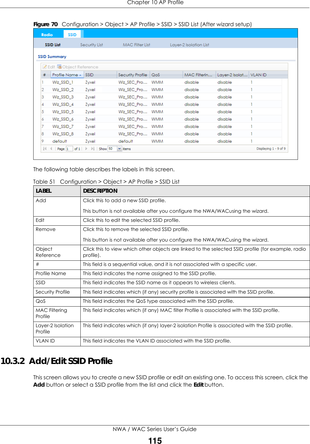
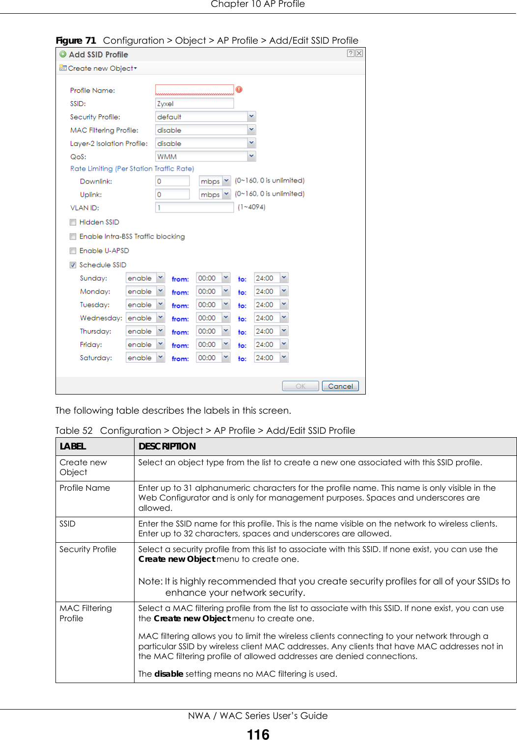
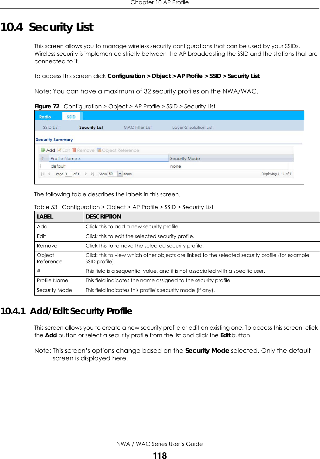
ZyXEL Communications NWA5123-ACHD 802.11ac Wave2 Dual-Radio Unified Access Point / 802.11ac Wave2 Dual-Radio Access Point / 802.11ac Wave2 Dual-Radio Nebula Cloud Managed Access Point User Manual Book
ZyXEL Communications Corporation 802.11ac Wave2 Dual-Radio Unified Access Point / 802.11ac Wave2 Dual-Radio Access Point / 802.11ac Wave2 Dual-Radio Nebula Cloud Managed Access Point Book
Contents
- 1. Users Manual-1
- 2. Users Manual-2
Users Manual-2
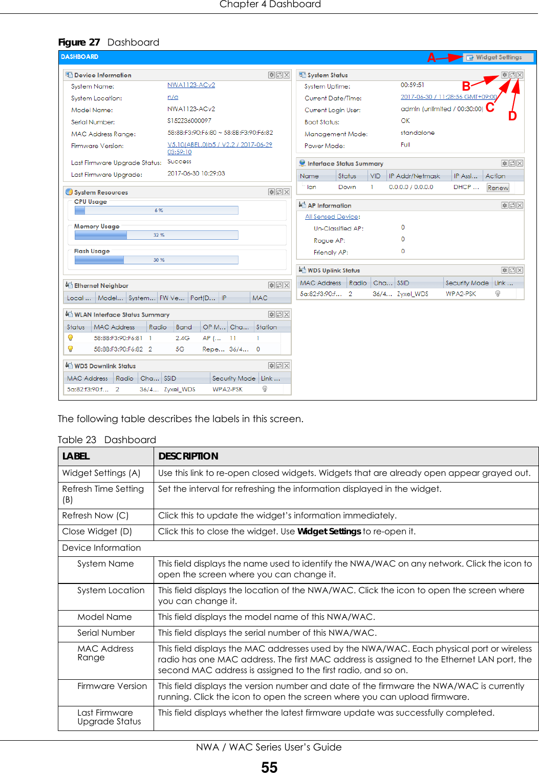
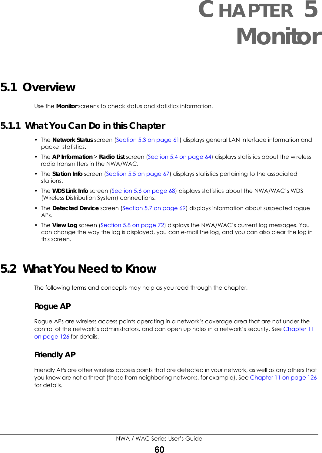
![Chapter 5 MonitorNWA / WAC Series User’s Guide74The Web Configurator saves the filter settings if you leave the View Log screen and return to it later.Destination AddressThis displays when you show the filter. Type the IP address of the destination of the incoming packet when the log message was generated. Do not include the port in this filter.Source Interface This displays when you show the filter. Select the source interface of the packet that generated the log message. Destination InterfaceThis displays when you show the filter. Select the destination interface of the packet that generated the log message. Protocol This displays when you show the filter. Select a service protocol whose log messages you would like to see. Keyword This displays when you show the filter. Type a keyword to look for in the Message, Source, Destination and Note fields. If a match is found in any field, the log message is displayed. You can use up to 63 alphanumeric characters and the underscore, as well as punctuation marks ()’ ,:;?! +-*/= #$% @ ; the period, double quotes, and brackets are not allowed.Search This displays when you show the filter. Click this button to update the log using the current filter settings.Email Log Now Click this button to send log messages to the Active e-mail addresses specified in the Send Log To field on the Configuration > Log & Report > Log Settings screen.Refresh Click this to update the list of logs.Clear Log Click this button to clear the whole log, regardless of what is currently displayed on the screen.#This field is a sequential value, and it is not associated with a specific log message.Time This field displays the time the log message was recorded.Priority This field displays the priority of the log message. It has the same range of values as the Priority field above.Category This field displays the log that generated the log message. It is the same value used in the Display and (other) Category fields.Message This field displays the reason the log message was generated. The text “[count=x]”, where x is a number, appears at the end of the Message field if log consolidation is turned on and multiple entries were aggregated to generate into this one.Source This field displays the source IP address and the port number in the event that generated the log message.Source Interface This field displays the source interface of the packet that generated the log message.Destination This field displays the destination IP address and the port number of the event that generated the log message.Destination InterfaceThis field displays the destination interface of the packet that generated the log message.Protocol This field displays the service protocol in the event that generated the log message.Note This field displays any additional information about the log message.Table 33 Monitor > Log > View Log (continued)LABEL DESCRIPTION](https://usermanual.wiki/ZyXEL-Communications/NWA5123-ACHD.Users-Manual-2/User-Guide-3558603-Page-22.png)
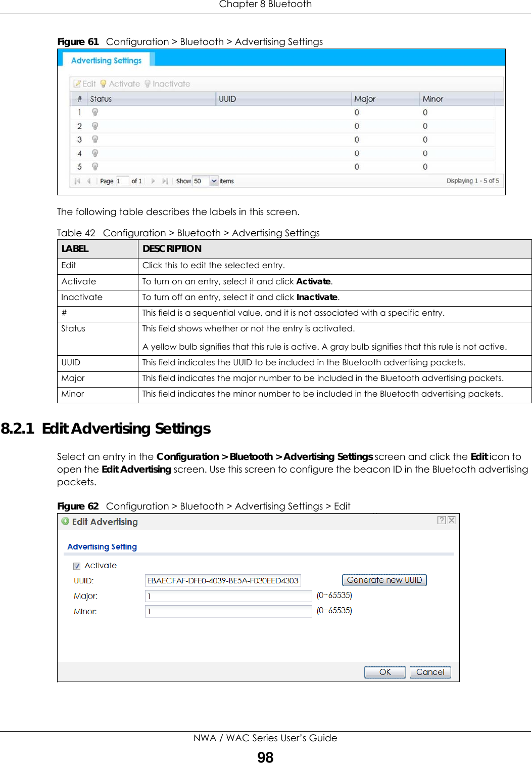
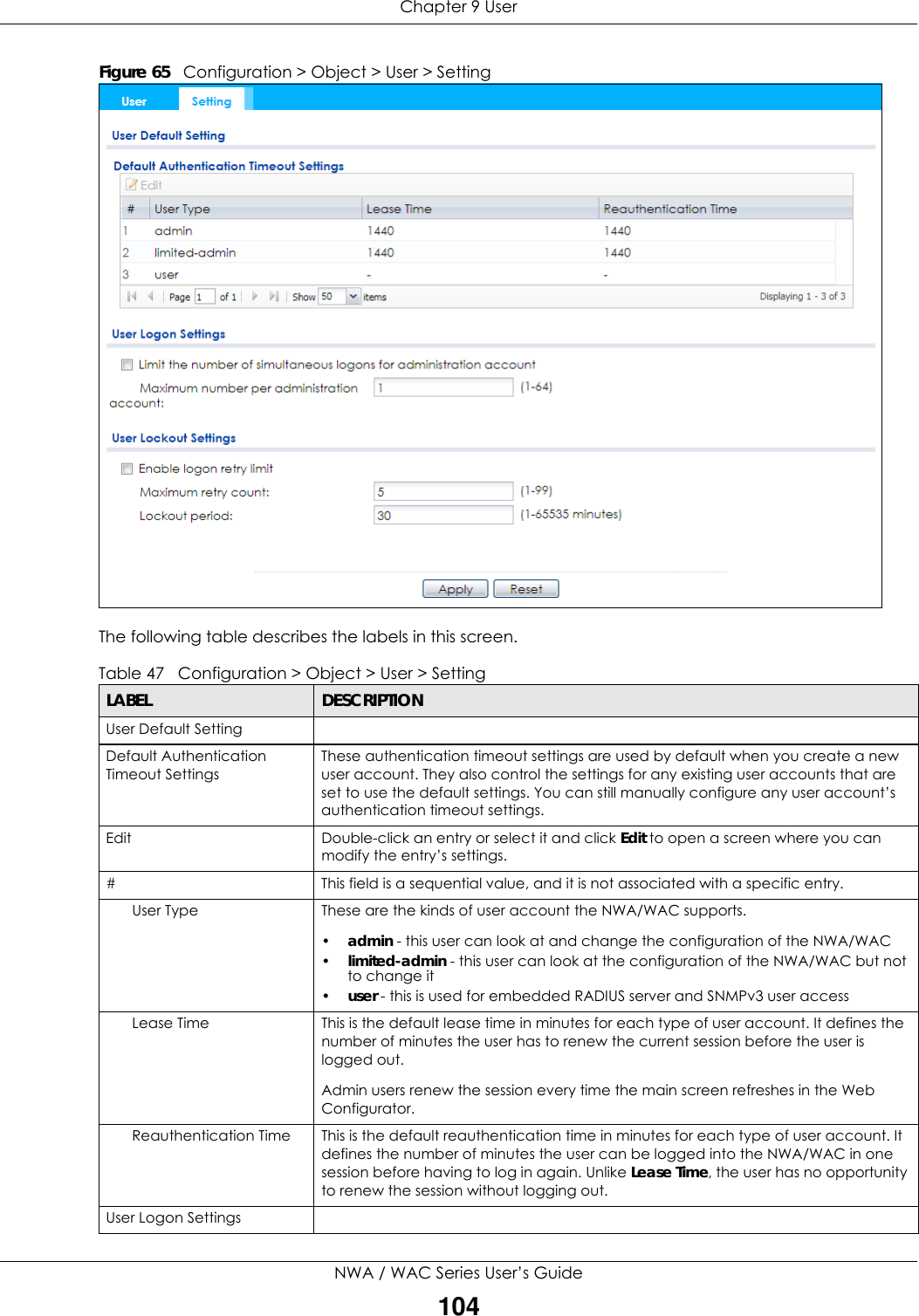
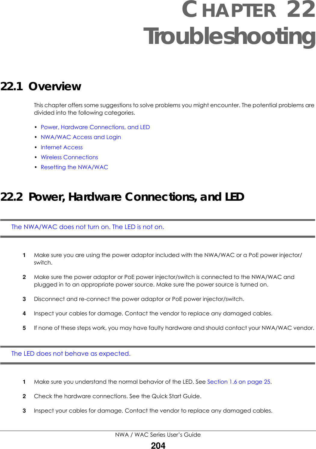
![Chapter 9 UserNWA / WAC Series User’s Guide1019.2 User SummaryThe User screen provides a summary of all user accounts. To access this screen click Configuration > Object > User.Figure 63 Configuration > Object > UserThe following table describes the labels in this screen. 9.2.1 Add/Edit UserThe User Add/Edit screen allows you to create a new user account or edit an existing one. 9.2.1.1 Rules for User NamesEnter a user name from 1 to 31 characters.The user name can only contain the following characters:• Alphanumeric A-z 0-9 (there is no unicode support)• _ [underscores] Table 45 Configuration > Object > UserLABEL DESCRIPTIONAdd Click this to create a new entry.Edit Double-click an entry or select it and click Edit to open a screen where you can modify the entry’s settings. Remove To remove an entry, select it and click Remove. The NWA/WAC confirms you want to remove it before doing so.Object Reference Select an entry and click Object Reference to open a screen that shows which settings use the entry.# This field is a sequential value, and it is not associated with a specific user.User Name This field displays the user name of each user.User Type This field displays type of user this account was configured as.•admin - this user can look at and change the configuration of the NWA/WAC•limited-admin - this user can look at the configuration of the NWA/WAC but not to change it•user - this user has access to the NWA/WAC’s services but cannot look at the configurationDescription This field displays the description for each user.](https://usermanual.wiki/ZyXEL-Communications/NWA5123-ACHD.Users-Manual-2/User-Guide-3558603-Page-49.png)
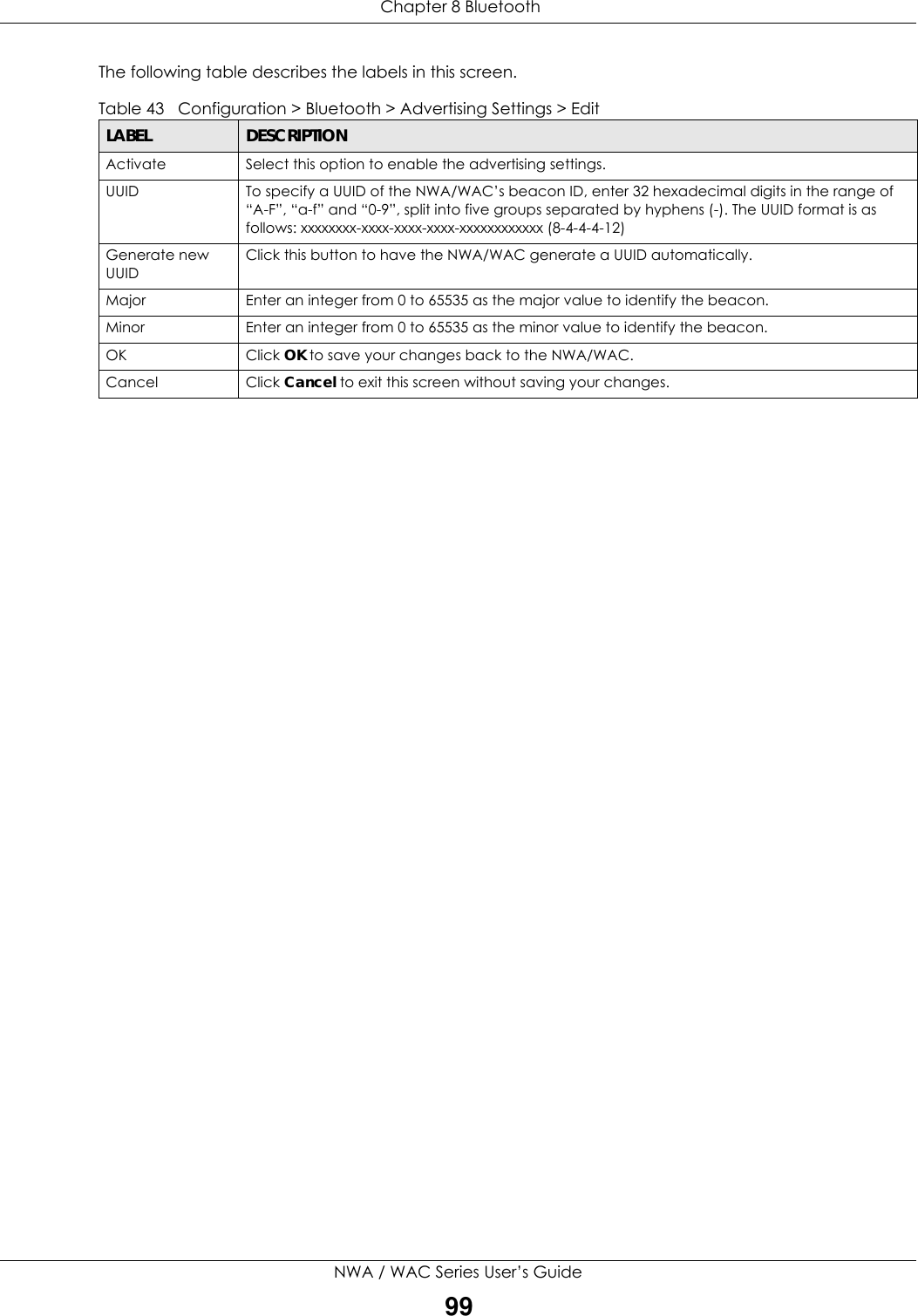
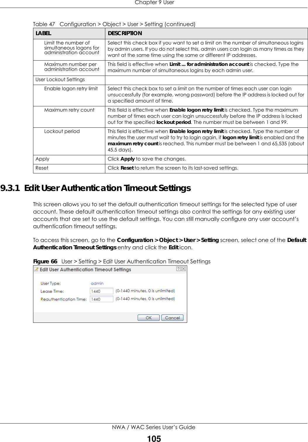
![Chapter 9 UserNWA / WAC Series User’s Guide102• - [dashes]The first character must be alphabetical (A-Z a-z), an underscore (_), or a dash (-). Other limitations on user names are:• User names are case-sensitive. If you enter a user 'bob' but use 'BOB' when connecting via CIFS or FTP, it will use the account settings used for 'BOB' not ‘bob’.• User names have to be different than user group names.• Here are the reserved user names:To access this screen, go to the User screen, and click Add or Edit.Figure 64 Configuration > Object > User > Add/Edit A UserThe following table describes the labels in this screen. •adm •admin •any •bin •daemon•debug •devicehaecived•ftp •games •halt•ldap-users •lp •mail •news •nobody• operator • radius-users • root • shutdown • sshd• sync • uucp • zyxelTable 46 Configuration > User > User > Add/Edit A UserLABEL DESCRIPTIONUser Name Type the user name for this user account. You may use 1-31 alphanumeric characters, underscores(_), or dashes (-), but the first character cannot be a number. This value is case-sensitive. User names have to be different than user group names, and some words are reserved.User Type Select what type of user this is. Choices are:•admin - this user can look at and change the configuration of the NWA/WAC•limited-admin - this user can look at the configuration of the NWA/WAC but not to change it•user - this is used for embedded RADIUS server and SNMPv3 user accessPassword Enter the password of this user account. It can consist of 4 - 63 alphanumeric characters.Retype Re-enter the password to make sure you have entered it correctly.Description Enter the description of each user, if any. You can use up to 60 printable ASCII characters. Default descriptions are provided.](https://usermanual.wiki/ZyXEL-Communications/NWA5123-ACHD.Users-Manual-2/User-Guide-3558603-Page-50.png)
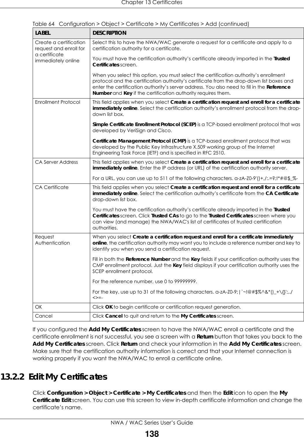
![Chapter 13 CertificatesNWA / WAC Series User’s Guide137The following table describes the labels in this screen. Table 64 Configuration > Object > Certificate > My Certificates > AddLABEL DESCRIPTIONName Type a name to identify this certificate. You can use up to 31 alphanumeric and ;‘~!@#$%^&()_+[]{}’,.=- characters.Subject Information Use these fields to record information that identifies the owner of the certificate. You do not have to fill in every field, although you must specify a Host IP Address, Host Domain Name, or E-Mail. The certification authority may add fields (such as a serial number) to the subject information when it issues a certificate. It is recommended that each certificate have unique subject information.Select a radio button to identify the certificate’s owner by IP address, domain name or e-mail address. Type the IP address (in dotted decimal notation), domain name or e-mail address in the field provided. The domain name or e-mail address is for identification purposes only and can be any string.A domain name can be up to 255 characters. You can use alphanumeric characters, the hyphen and periods.An e-mail address can be up to 63 characters. You can use alphanumeric characters, the hyphen, the @ symbol, periods and the underscore.Organizational Unit Identify the organizational unit or department to which the certificate owner belongs. You can use up to 31 characters. You can use alphanumeric characters, the hyphen and the underscore.Organization Identify the company or group to which the certificate owner belongs. You can use up to 31 characters. You can use alphanumeric characters, the hyphen and the underscore.Town (City) Identify the town or city where the certificate owner is located. You can use up to 31 characters. You can use alphanumeric characters, the hyphen and the underscore.State (Province) Identify the state or province where the certificate owner is located. You can use up to 31 characters. You can use alphanumeric characters, the hyphen and the underscore.Country Identify the nation where the certificate owner is located. You can use up to 31 characters. You can use alphanumeric characters, the hyphen and the underscore.Key Type The NWA/WAC uses the RSA (Rivest, Shamir and Adleman) public-key encryption algorithm. SHA1 (Secure Hash Algorithm) and SHA2 are hash algorithms used to authenticate packet data. SHA2-256 or SHA2-512 are part of the SHA2 set of cryptographic functions and they are considered even more secure than SHA1.Select a key type from RSA-SHA256 and RSA-SHA512.Key Length Select a number from the drop-down list box to determine how many bits the key should use (1024 to 2048). The longer the key, the more secure it is. A longer key also uses more PKI storage space.Extended Key Usage Select Server Authentication to allow a web server to send clients the certificate to authenticate itself.Select Client Authentication to use the certificate’s key to authenticate clients to the secure gateway.These radio buttons deal with how and when the certificate is to be generated.Create a self-signed certificateSelect this to have the NWA/WAC generate the certificate and act as the Certification Authority (CA) itself. This way you do not need to apply to a certification authority for certificates.Create a certification request and save it locally for later manual enrollmentSelect this to have the NWA/WAC generate and store a request for a certificate. Use the My Certificate Edit screen to view the certification request and copy it to send to the certification authority.Copy the certification request from the My Certificate Edit screen and then send it to the certification authority.](https://usermanual.wiki/ZyXEL-Communications/NWA5123-ACHD.Users-Manual-2/User-Guide-3558603-Page-85.png)
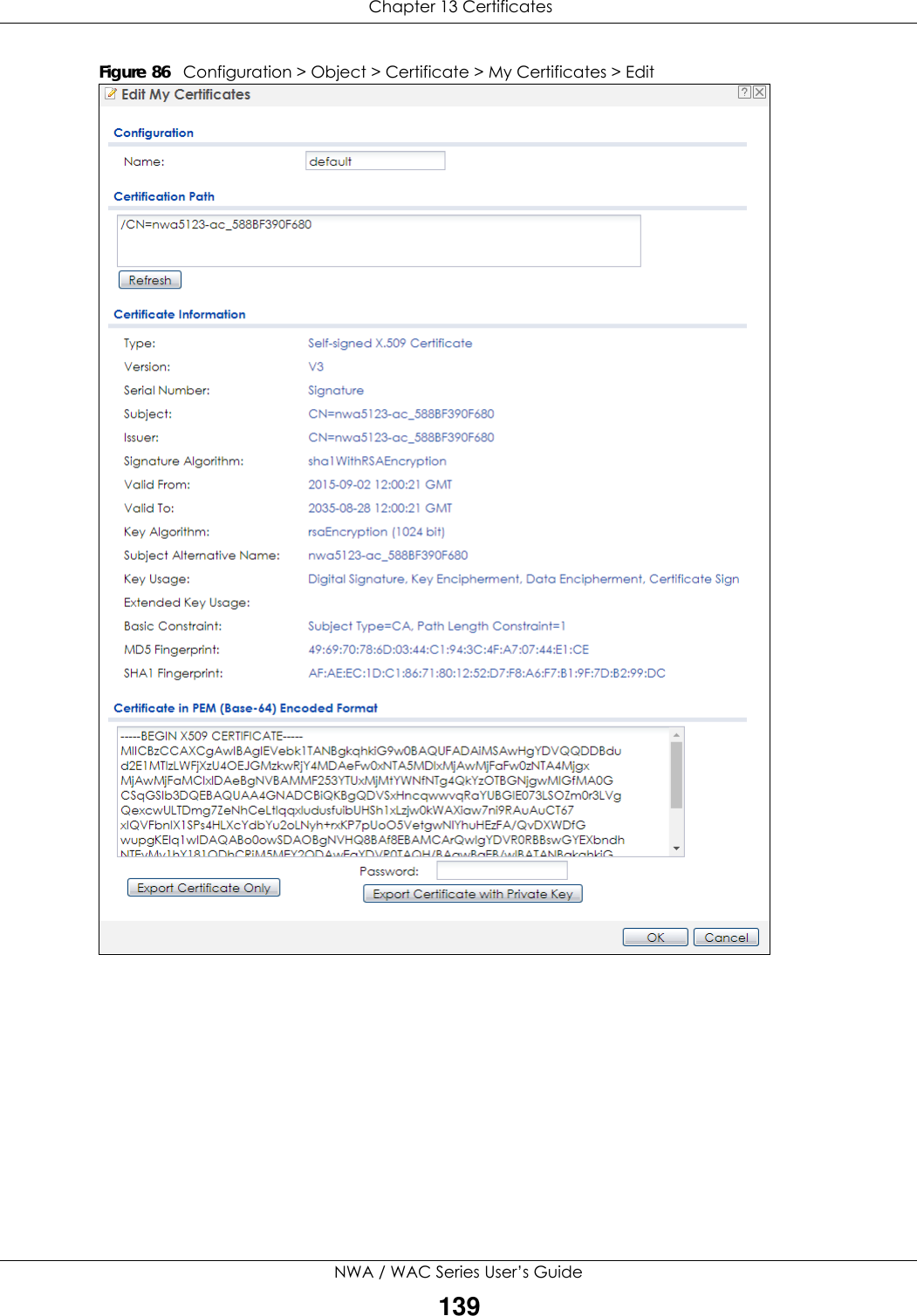
![Chapter 13 CertificatesNWA / WAC Series User’s Guide140The following table describes the labels in this screen. Table 65 Configuration > Object > Certificate > My Certificates > EditLABEL DESCRIPTIONName This field displays the identifying name of this certificate. You can use up to 31 alphanumeric and ;‘~!@#$%^&()_+[]{}’,.=- characters.Certification Path This field displays for a certificate, not a certification request.Click the Refresh button to have this read-only text box display the hierarchy of certification authorities that validate the certificate (and the certificate itself).If the issuing certification authority is one that you have imported as a trusted certification authority, it may be the only certification authority in the list (along with the certificate itself). If the certificate is a self-signed certificate, the certificate itself is the only one in the list. The NWA/WAC does not trust the certificate and displays “Not trusted” in this field if any certificate on the path has expired or been revoked.Refresh Click Refresh to display the certification path.Certificate InformationThese read-only fields display detailed information about the certificate. Type This field displays general information about the certificate. CA-signed means that a Certification Authority signed the certificate. Self-signed means that the certificate’s owner signed the certificate (not a certification authority). “X.509” means that this certificate was created and signed according to the ITU-T X.509 recommendation that defines the formats for public-key certificates.Version This field displays the X.509 version number. “Serial Number This field displays the certificate’s identification number given by the certification authority or generated by the NWA/WAC.Subject This field displays information that identifies the owner of the certificate, such as Common Name (CN), Organizational Unit (OU), Organization (O), State (ST), and Country (C).Issuer This field displays identifying information about the certificate’s issuing certification authority, such as Common Name, Organizational Unit, Organization and Country. With self-signed certificates, this is the same as the Subject Name field.“none” displays for a certification request. Signature Algorithm This field displays the type of algorithm that was used to sign the certificate. Valid From This field displays the date that the certificate becomes applicable. “none” displays for a certification request. Valid To This field displays the date that the certificate expires. The text displays in red and includes an Expired! message if the certificate has expired. “none” displays for a certification request. Key Algorithm This field displays the type of algorithm that was used to generate the certificate’s key pair (the NWA/WAC uses RSA encryption) and the length of the key set in bits (1024 bits for example).Subject Alternative NameThis field displays the certificate owner‘s IP address (IP), domain name (DNS) or e-mail address (EMAIL). Key Usage This field displays for what functions the certificate’s key can be used. For example, “DigitalSignature” means that the key can be used to sign certificates and “KeyEncipherment” means that the key can be used to encrypt text.Extended Key Usage This field displays for what EKU (Extended Key Usage) functions the certificate’s key can be used. Basic Constraint This field displays general information about the certificate. For example, Subject Type=CA means that this is a certification authority’s certificate and “Path Length Constraint=1” means that there can only be one certification authority in the certificate’s path. This field does not display for a certification request.](https://usermanual.wiki/ZyXEL-Communications/NWA5123-ACHD.Users-Manual-2/User-Guide-3558603-Page-88.png)
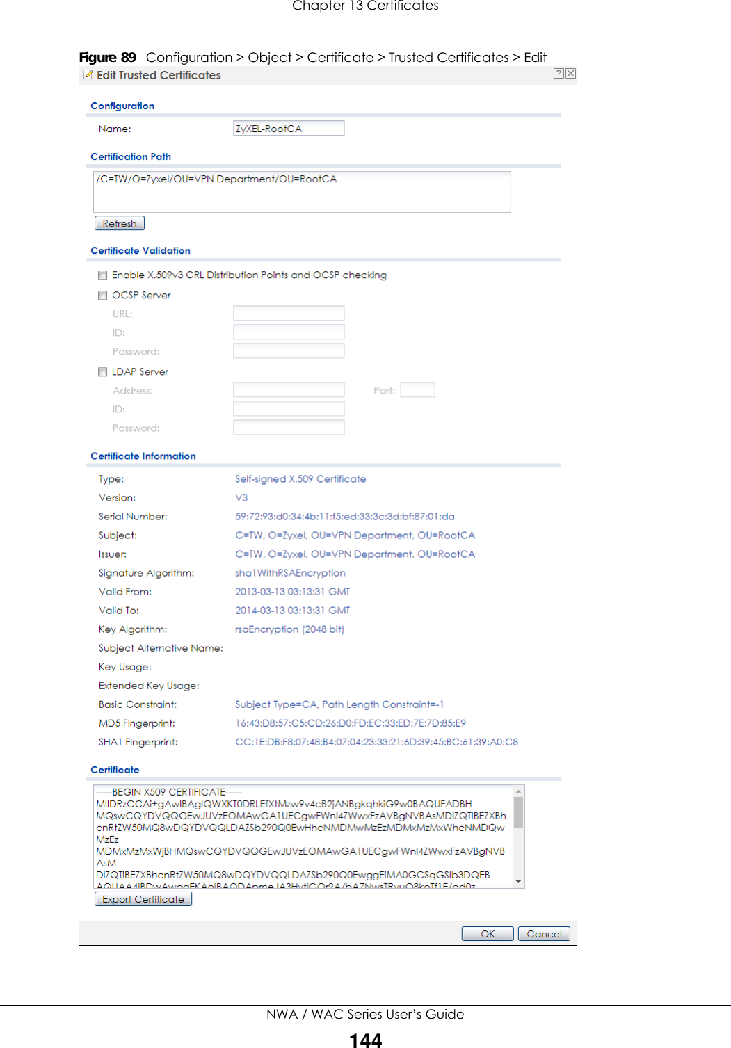
![Chapter 13 CertificatesNWA / WAC Series User’s Guide145The following table describes the labels in this screen. Table 68 Configuration > Object > Certificate > Trusted Certificates > EditLABEL DESCRIPTIONName This field displays the identifying name of this certificate. You can change the name. You can use up to 31 alphanumeric and ;‘~!@#$%^&()_+[]{}’,.=- characters.Certification Path Click the Refresh button to have this read-only text box display the end entity’s certificate and a list of certification authority certificates that shows the hierarchy of certification authorities that validate the end entity’s certificate. If the issuing certification authority is one that you have imported as a trusted certificate, it may be the only certification authority in the list (along with the end entity’s own certificate). The NWA/WAC does not trust the end entity’s certificate and displays “Not trusted” in this field if any certificate on the path has expired or been revoked.Refresh Click Refresh to display the certification path.Enable X.509v3 CRL Distribution Points and OCSP checking Select this check box to have the NWA/WAC check incoming certificates that are signed by this certificate against a Certificate Revocation List (CRL) or an OCSP server. You also need to configure the OSCP or LDAP server details.OCSP Server Select this check box if the directory server uses OCSP (Online Certificate Status Protocol).URL Type the protocol, IP address and pathname of the OCSP server. ID The NWA/WAC may need to authenticate itself in order to assess the OCSP server. Type the login name (up to 31 ASCII characters) from the entity maintaining the server (usually a certification authority).Password Type the password (up to 31 ASCII characters) from the entity maintaining the OCSP server (usually a certification authority).LDAP Server Select this check box if the directory server uses LDAP (Lightweight Directory Access Protocol). LDAP is a protocol over TCP that specifies how clients access directories of certificates and lists of revoked certificates.Address Type the IP address (in dotted decimal notation) of the directory server. Port Use this field to specify the LDAP server port number. You must use the same server port number that the directory server uses. 389 is the default server port number for LDAP.ID The NWA/WAC may need to authenticate itself in order to assess the CRL directory server. Type the login name (up to 31 ASCII characters) from the entity maintaining the server (usually a certification authority).Password Type the password (up to 31 ASCII characters) from the entity maintaining the CRL directory server (usually a certification authority).Certificate InformationThese read-only fields display detailed information about the certificate. Type This field displays general information about the certificate. CA-signed means that a Certification Authority signed the certificate. Self-signed means that the certificate’s owner signed the certificate (not a certification authority). X.509 means that this certificate was created and signed according to the ITU-T X.509 recommendation that defines the formats for public-key certificates.Version This field displays the X.509 version number. Serial Number This field displays the certificate’s identification number given by the certification authority.Subject This field displays information that identifies the owner of the certificate, such as Common Name (CN), Organizational Unit (OU), Organization (O) and Country (C).Issuer This field displays identifying information about the certificate’s issuing certification authority, such as Common Name, Organizational Unit, Organization and Country. With self-signed certificates, this is the same information as in the Subject Name field.Signature Algorithm This field displays the type of algorithm that was used to sign the certificate. Some certification authorities use rsa-pkcs1-sha1 (RSA public-private key encryption algorithm and the SHA1 hash algorithm). Other certification authorities may use rsa-pkcs1-md5 (RSA public-private key encryption algorithm and the MD5 hash algorithm).](https://usermanual.wiki/ZyXEL-Communications/NWA5123-ACHD.Users-Manual-2/User-Guide-3558603-Page-93.png)
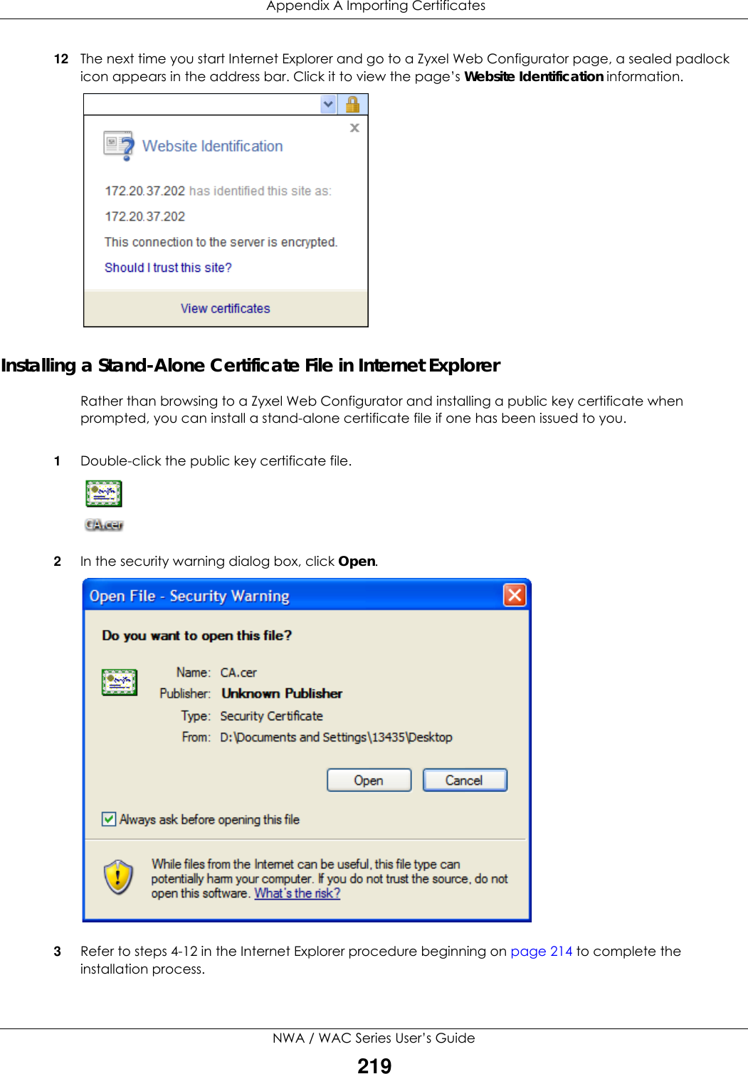
![Chapter 14 SystemNWA / WAC Series User’s Guide1661Launch the SSH client and specify the connection information (IP address, port number) for the NWA/WAC. 2Configure the SSH client to accept connection using SSH version 1. 3A window displays prompting you to store the host key in you computer. Click Yes to continue. Figure 104 SSH Example 1: Store Host KeyEnter the password to log in to the NWA/WAC. The CLI screen displays next. 14.5.5.2 Example 2: LinuxThis section describes how to access the NWA/WAC using the OpenSSH client program that comes with most Linux distributions. 1Test whether the SSH service is available on the NWA/WAC. Enter “telnet 192.168.1.2 22” at a terminal prompt and press [ENTER]. The computer attempts to connect to port 22 on the NWA/WAC (using the default IP address of 192.168.1.2). A message displays indicating the SSH protocol version supported by the NWA/WAC. Figure 105 SSH Example 2: Test 2Enter “ssh –1 192.168.1.2”. This command forces your computer to connect to the NWA/WAC using SSH version 1. If this is the first time you are connecting to the NWA/WAC using SSH, a message displays prompting you to save the host information of the NWA/WAC. Type “yes” and press [ENTER]. Then enter the password to log in to the NWA/WAC. Figure 106 SSH Example 2: Log in$ telnet 192.168.1.2 22Trying 192.168.1.2...Connected to 192.168.1.2.Escape character is '^]'.SSH-1.5-1.0.0$ ssh –1 192.168.1.2The authenticity of host '192.168.1.2 (192.168.1.2)' can't be established.RSA1 key fingerprint is 21:6c:07:25:7e:f4:75:80:ec:af:bd:d4:3d:80:53:d1.Are you sure you want to continue connecting (yes/no)? yesWarning: Permanently added '192.168.1.2' (RSA1) to the list of known hosts.Administrator@192.168.1.2's password:](https://usermanual.wiki/ZyXEL-Communications/NWA5123-ACHD.Users-Manual-2/User-Guide-3558603-Page-114.png)
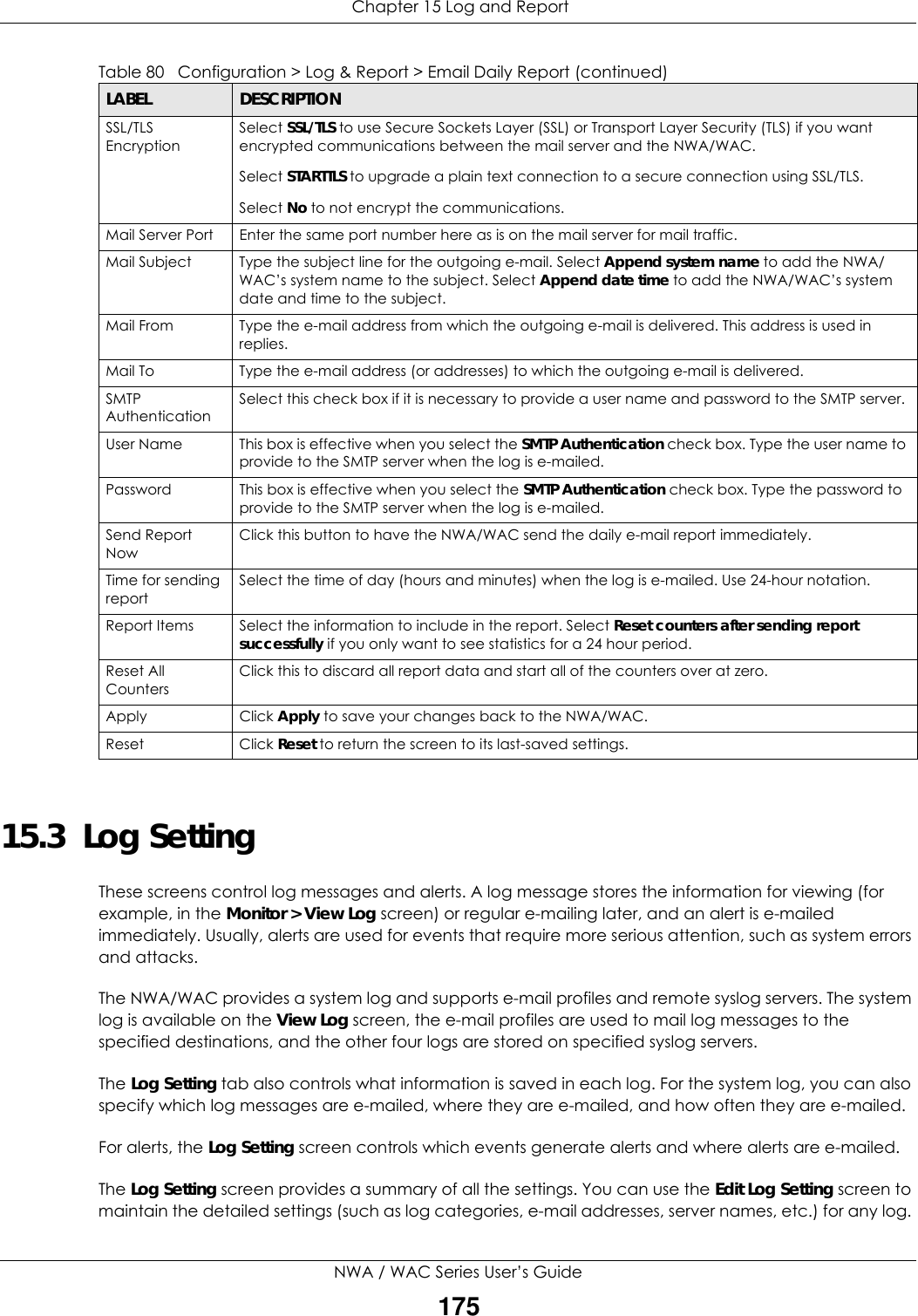
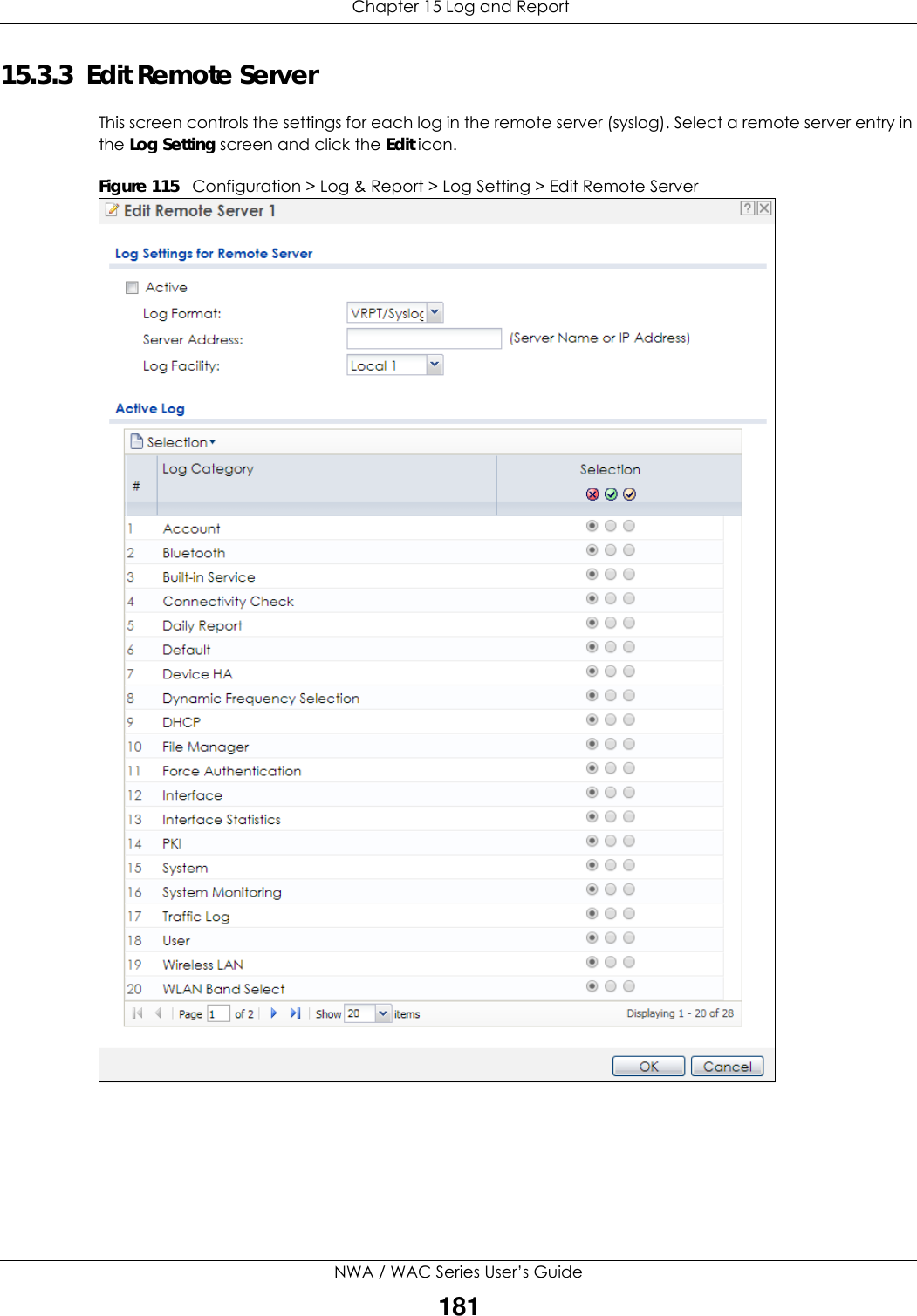
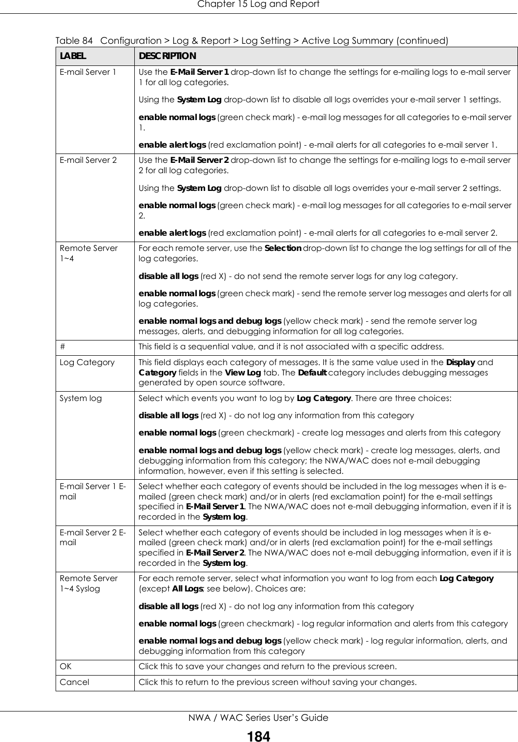
![Chapter 15 Log and ReportNWA / WAC Series User’s Guide180E-mail Server 1 Use the E-Mail Server 1 drop-down list to change the settings for e-mailing logs to e-mail server 1 for all log categories.Using the System Log drop-down list to disable all logs overrides your e-mail server 1 settings.enable normal logs (green check mark) - e-mail log messages for all categories to e-mail server 1.enable alert logs (red exclamation point) - e-mail alerts for all categories to e-mail server 1.E-mail Server 2 Use the E-Mail Server 2 drop-down list to change the settings for e-mailing logs to e-mail server 2 for all log categories.Using the System Log drop-down list to disable all logs overrides your e-mail server 2 settings.enable normal logs (green check mark) - e-mail log messages for all categories to e-mail server 2.enable alert logs (red exclamation point) - e-mail alerts for all categories to e-mail server 2.# This field is a sequential value, and it is not associated with a specific address.Log Category This field displays each category of messages. It is the same value used in the Display and Category fields in the View Log tab. The Default category includes debugging messages generated by open source software.System log Select which events you want to log by Log Category. There are three choices:disable all logs (red X) - do not log any information from this categoryenable normal logs (green checkmark) - create log messages and alerts from this categoryenable normal logs and debug logs (yellow check mark) - create log messages, alerts, and debugging information from this category; the NWA/WAC does not e-mail debugging information, however, even if this setting is selected.E-mail Server 1 Select whether each category of events should be included in the log messages when it is e-mailed (green check mark) and/or in alerts (red exclamation point) for the e-mail settings specified in E-Mail Server 1. The NWA/WAC does not e-mail debugging information, even if it is recorded in the System log.E-mail Server 2 Select whether each category of events should be included in log messages when it is e-mailed (green check mark) and/or in alerts (red exclamation point) for the e-mail settings specified in E-Mail Server 2. The NWA/WAC does not e-mail debugging information, even if it is recorded in the System log.Log ConsolidationActive Select this to activate log consolidation. Log consolidation aggregates multiple log messages that arrive within the specified Log Consolidation Interval. In the View Log tab, the text “[count=x]”, where x is the number of original log messages, is appended at the end of the Message field, when multiple log messages were aggregated.Log Consolidation Interval Type how often, in seconds, to consolidate log information. If the same log message appears multiple times, it is aggregated into one log message with the text “[count=x]”, where x is the number of original log messages, appended at the end of the Message field.OK Click this to save your changes and return to the previous screen.Cancel Click this to return to the previous screen without saving your changes.Table 82 Configuration > Log & Report > Log Setting > Edit System Log Setting (continued)LABEL DESCRIPTION](https://usermanual.wiki/ZyXEL-Communications/NWA5123-ACHD.Users-Manual-2/User-Guide-3558603-Page-128.png)
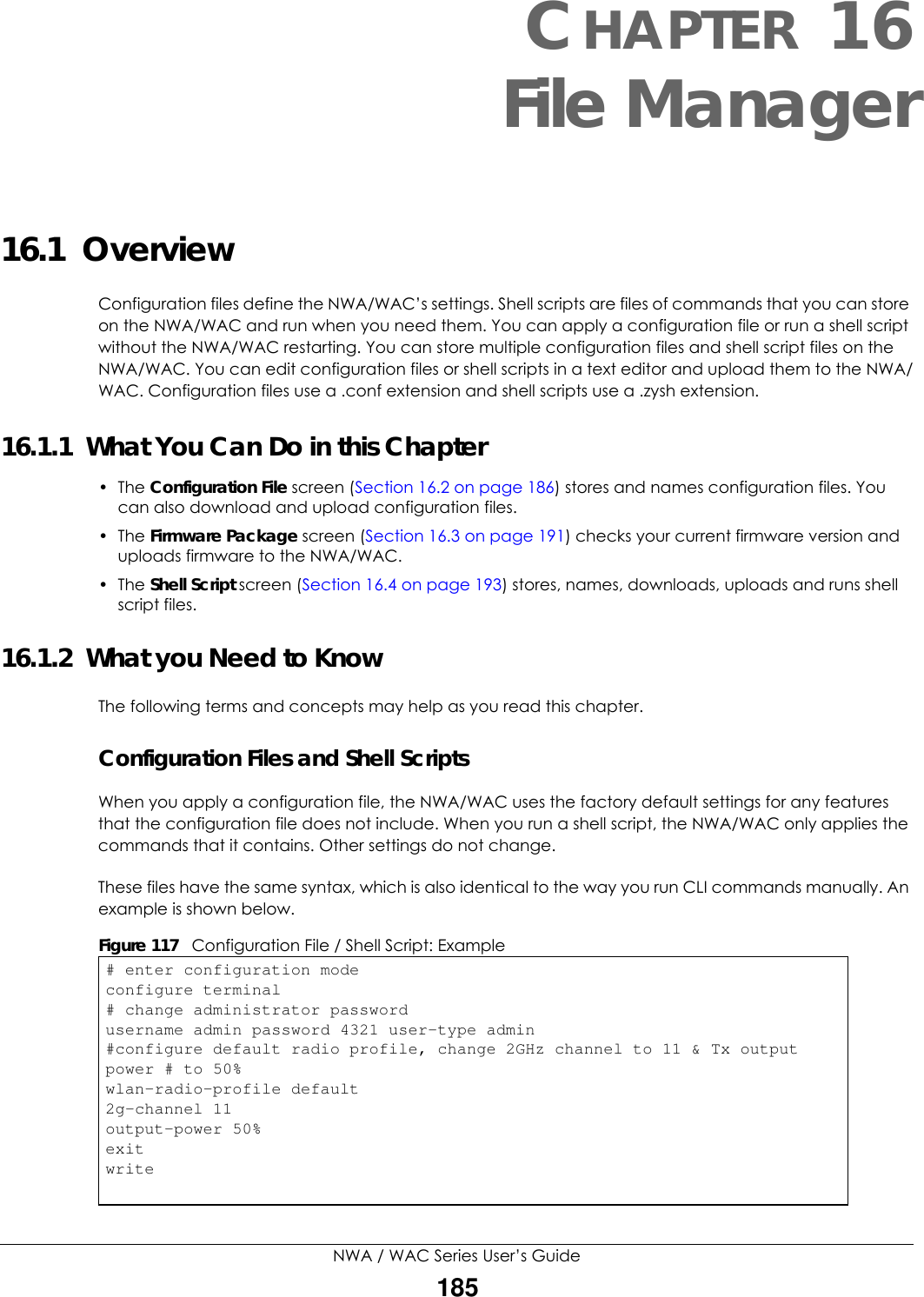
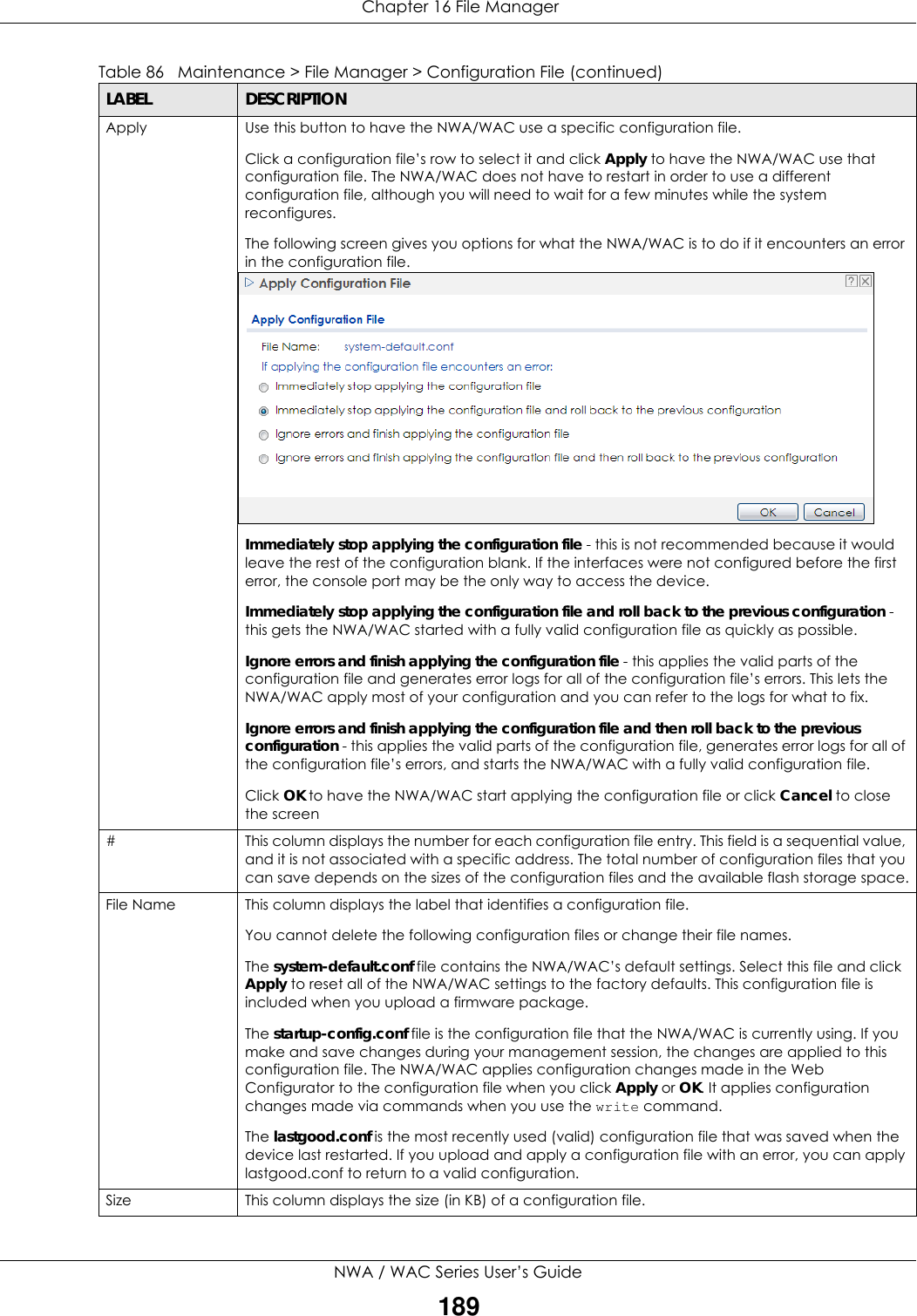
![Chapter 16 File ManagerNWA / WAC Series User’s Guide188The following table describes the labels in this screen. Table 86 Maintenance > File Manager > Configuration FileLABEL DESCRIPTIONRename Use this button to change the label of a configuration file on the NWA/WAC. You can only rename manually saved configuration files. You cannot rename the lastgood.conf, system-default.conf and startup-config.conf files. You cannot rename a configuration file to the name of another configuration file in the NWA/WAC. Click a configuration file’s row to select it and click Rename to open the Rename File screen. Specify the new name for the configuration file. Use up to 25 characters (including a-zA-Z0-9;‘~!@#$%^&()_+[]{}’,.=-). Click OK to save the duplicate or click Cancel to close the screen without saving a duplicate of the configuration file.Remove Click a configuration file’s row to select it and click Remove to delete it from the NWA/WAC. You can only delete manually saved configuration files. You cannot delete the system-default.conf, startup-config.conf and lastgood.conf files.A pop-up window asks you to confirm that you want to delete the configuration file. Click OK to delete the configuration file or click Cancel to close the screen without deleting the configuration file.Download Click a configuration file’s row to select it and click Download to save the configuration to your computer.Copy Use this button to save a duplicate of a configuration file on the NWA/WAC. Click a configuration file’s row to select it and click Copy to open the Copy File screen. Specify a name for the duplicate configuration file. Use up to 25 characters (including a-zA-Z0-9;‘~!@#$%^&()_+[]{}’,.=-). Click OK to save the duplicate or click Cancel to close the screen without saving a duplicate of the configuration file.](https://usermanual.wiki/ZyXEL-Communications/NWA5123-ACHD.Users-Manual-2/User-Guide-3558603-Page-136.png)
![Chapter 16 File ManagerNWA / WAC Series User’s Guide1919Wait for the file transfer to complete.10 Enter “quit” to exit the ftp prompt.16.3 Firmware Package Click Maintenance > File Manager > Firmware Package to open this screen. Use the Firmware Package screen to check your current firmware version and upload firmware to the NWA/WAC.Note: The Web Configurator is the recommended method for uploading firmware. You only need to use the command line interface if you need to recover the firmware. See the CLI Reference Guide for how to determine if you need to recover the firmware and how to recover it.Find the firmware package at www.zyxel.com in a file that (usually) uses a .bin extension. The firmware update can take up to five minutes. Do not turn off or reset the NWA/WAC while the firmware update is in progress!C:\>ftp 192.168.1.2Connected to 192.168.1.2.220---------- Welcome to Pure-FTPd [privsep] [TLS] ----------220-You are user number 1 of 5 allowed.220-Local time is now 21:28. Server port: 21.220-This is a private system - No anonymous login220 You will be disconnected after 600 minutes of inactivity.User (192.168.1.2:(none)): admin331 User admin OK. Password requiredPassword:230 OK. Current restricted directory is /ftp> cd conf250 OK. Current directory is /confftp> ls200 PORT command successful150 Connecting to port 5001lastgood.confstartup-config.confsystem-default.conf226 3 matches totalftp: 57 bytes received in 0.33Seconds 0.17Kbytes/sec.ftp> get startup-config.conf200 PORT command successful150 Connecting to port 5002226-File successfully transferred226 0.002 seconds (measured here), 1.66 Mbytes per secondftp: 2928 bytes received in 0.02Seconds 183.00Kbytes/sec.ftp>](https://usermanual.wiki/ZyXEL-Communications/NWA5123-ACHD.Users-Manual-2/User-Guide-3558603-Page-139.png)
![Chapter 16 File ManagerNWA / WAC Series User’s Guide1932The FTP server IP address of the NWA/WAC in standalone AP mode is 192.168.1.2, so set your computer to use a static IP address from 192.168.1.3 ~192.168.1.254.3Use an FTP client on your computer to connect to the NWA/WAC. For example, in the Windows command prompt, type ftp 192.168.1.2. Keep the console session connected in order to see when the firmware recovery finishes. 4Enter your user name when prompted.5Enter your password as requested.6Enter “hash” for FTP to print a `#' character for every 1024 bytes of data you upload so that you can watch the file transfer progress.7Enter “bin” to set the transfer mode to binary.8Transfer the firmware file from your computer to the NWA/WAC. Type put followed by the path and name of the firmware file. This examples uses put C:\ftproot\NWA/WAC_FW\510ABFH0C0.bin. 9Wait for the file transfer to complete.10 Enter “quit” to exit the ftp prompt.16.4 Shell Script Use shell script files to have the NWA/WAC use commands that you specify. Use a text editor to create the shell script files. They must use a “.zysh” filename extension. Click Maintenance > File Manager > Shell Script to open this screen. Use the Shell Script screen to store, name, download, upload and run shell script files. You can store multiple shell script files on the NWA/WAC at the same time. Note: You should include write commands in your scripts. If you do not use the write command, the changes will be lost when the NWA/WAC restarts. You could use multiple write commands in a long script.C:\>ftp 192.168.1.2Connected to 192.168.1.2.220---------- Welcome to Pure-FTPd [privsep] [TLS] ----------220-You are user number 1 of 5 allowed.220-Local time is now 21:28. Server port: 21.220-This is a private system - No anonymous login220 You will be disconnected after 600 minutes of inactivity.User (192.168.1.2:(none)): admin331 User admin OK. Password requiredPassword:230 OK. Current restricted directory is /ftp> hash Hash mark printing On ftp: (2048 bytes/hash mark) .ftp> bin200 TYPE is now 8-bit binaryftp> put C:\ftproot\NWA/WAC_FW\510ABFH0C0.bin](https://usermanual.wiki/ZyXEL-Communications/NWA5123-ACHD.Users-Manual-2/User-Guide-3558603-Page-141.png)
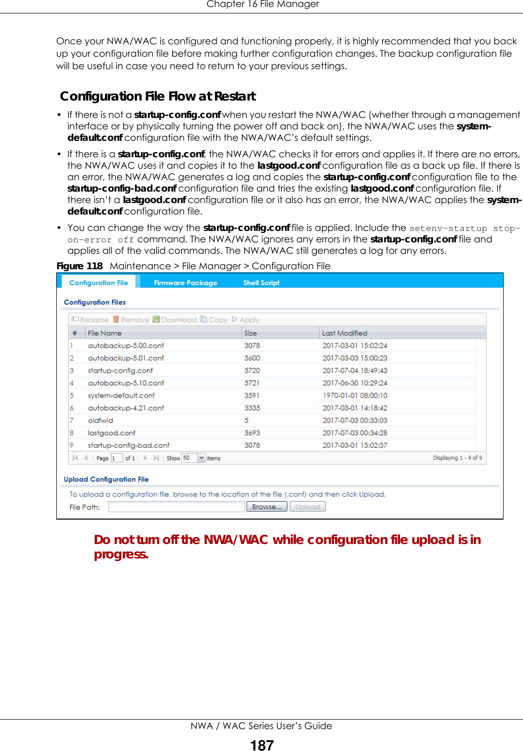
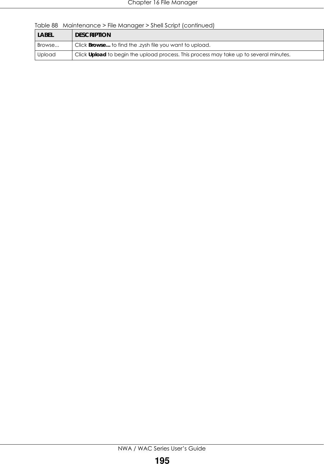
![Chapter 16 File ManagerNWA / WAC Series User’s Guide194Figure 121 Maintenance > File Manager > Shell Script Each field is described in the following table. Table 88 Maintenance > File Manager > Shell ScriptLABEL DESCRIPTIONRename Use this button to change the label of a shell script file on the NWA/WAC. You cannot rename a shell script to the name of another shell script in the NWA/WAC. Click a shell script’s row to select it and click Rename to open the Rename File screen. Specify the new name for the shell script file. Use up to 25 characters (including a-zA-Z0-9;‘~!@#$%^&()_+[]{}’,.=-). Click OK to save the duplicate or click Cancel to close the screen without saving a duplicate of the configuration file.Remove Click a shell script file’s row to select it and click Delete to delete the shell script file from the NWA/WAC. A pop-up window asks you to confirm that you want to delete the shell script file. Click OK to delete the shell script file or click Cancel to close the screen without deleting the shell script file.Download Click a shell script file’s row to select it and click Download to save the configuration to your computer.Copy Use this button to save a duplicate of a shell script file on the NWA/WAC. Click a shell script file’s row to select it and click Copy to open the Copy File screen. Specify a name for the duplicate file. Use up to 25 characters (including a-zA-Z0-9;‘~!@#$%^&()_+[]{}’,.=-). Click OK to save the duplicate or click Cancel to close the screen without saving a duplicate of the configuration file.Apply Use this button to have the NWA/WAC use a specific shell script file.Click a shell script file’s row to select it and click Apply to have the NWA/WAC use that shell script file. You may need to wait awhile for the NWA/WAC to finish applying the commands.#This column displays the number for each shell script file entry.File Name This column displays the label that identifies a shell script file.Size This column displays the size (in KB) of a shell script file.Last ModifiedThis column displays the date and time that the individual shell script files were last changed or saved.Upload Shell ScriptThe bottom part of the screen allows you to upload a new or previously saved shell script file from your computer to your NWA/WAC.File Path Type in the location of the file you want to upload in this field or click Browse... to find it.](https://usermanual.wiki/ZyXEL-Communications/NWA5123-ACHD.Users-Manual-2/User-Guide-3558603-Page-142.png)
![Chapter 22 TroubleshootingNWA / WAC Series User’s Guide206• Try to access the NWA/WAC using another service, such as Telnet. If you can access the NWA/WAC, check the remote management settings to find out why the NWA/WAC does not respond to HTTP. • If your computer is connected wirelessly, use a computer that is connected to a LAN/ETHERNET port.I forgot the password.1The default password is 1234.2If this does not work, you have to reset the device to its factory defaults. See Section 22.6 on page 212.I can see the Login screen, but I cannot log in to the NWA/WAC.1Make sure you have entered the user name and password correctly. The default password is 1234. This fields are case-sensitive, so make sure [Caps Lock] is not on.2You cannot log in to the web configurator while someone is using Telnet to access the NWA/WAC. Log out of the NWA/WAC in the other session, or ask the person who is logged in to log out.3Disconnect and re-connect the power adaptor or PoE power injector to the NWA/WAC. 4If this does not work, you have to reset the device to its factory defaults. See Section 22.6 on page 212.I cannot use FTP to upload / download the configuration file. / I cannot use FTP to upload new firmware. See the troubleshooting suggestions for I cannot see or access the Login screen in the web configurator. Ignore the suggestions about your browser.22.4 Internet AccessI cannot access the Internet.1Check the hardware connections, and make sure the LED is behaving as expected. See the Quick Start Guide and Section 22.2 on page 204.2Make sure the NWA/WAC is connected to a broadband modem or router with Internet access and your computer is set to obtain an dynamic IP address.](https://usermanual.wiki/ZyXEL-Communications/NWA5123-ACHD.Users-Manual-2/User-Guide-3558603-Page-154.png)