ZyXEL Communications NWA5123-ACHD 802.11ac Wave2 Dual-Radio Unified Access Point / 802.11ac Wave2 Dual-Radio Access Point / 802.11ac Wave2 Dual-Radio Nebula Cloud Managed Access Point User Manual Book
ZyXEL Communications Corporation 802.11ac Wave2 Dual-Radio Unified Access Point / 802.11ac Wave2 Dual-Radio Access Point / 802.11ac Wave2 Dual-Radio Nebula Cloud Managed Access Point Book
Contents
- 1. Users Manual-1
- 2. Users Manual-2
Users Manual-2

53
PART II
Technical Reference

NWA / WAC Series User’s Guide
54
CHAPTER 4
Dashboard
4.1 Overview
Use the Dashboard screens to check status information about the NWA/WAC.
4.1.1 What You Can Do in this Chapter
• The main Dashboard screen (Section 4.2 on page 54) displays the NWA/WAC’s general device
information, system status, system resource usage, and interface status. You can also display other
status screens for more information.
4.2 Dashboard
This screen is the first thing you see when you log into the NWA/WAC. It also appears every time you click
the Dashboard icon in the navigation panel. The Dashboard displays general device information, system
status, system resource usage, and interface status in widgets that you can re-arrange to suit your
needs. You can also collapse, refresh, and close individual widgets.
Chapter 4 Dashboard
NWA / WAC Series User’s Guide
55
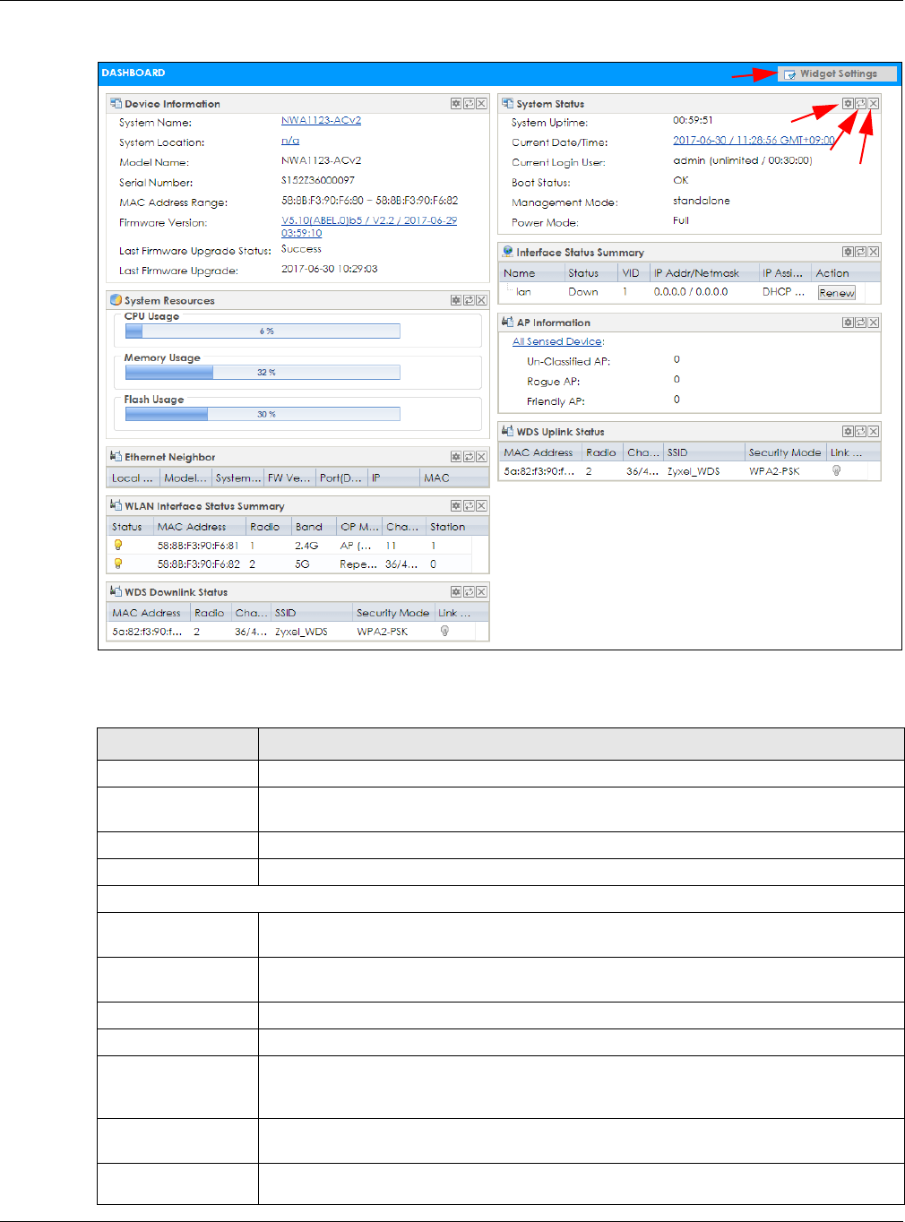
Figure 27 Dashboard
The following table describes the labels in this screen.
Table 23 Dashboard
LABEL DESCRIPTION
Widget Settings (A) Use this link to re-open closed widgets. Widgets that are already open appear grayed out.
Refresh Time Setting
(B)
Set the interval for refreshing the information displayed in the widget.
Refresh Now (C) Click this to update the widget’s information immediately.
Close Widget (D) Click this to close the widget. Use Widget Settings to re-open it.
Device Information
System Name This field displays the name used to identify the NWA/WAC on any network. Click the icon to
open the screen where you can change it.
System Location This field displays the location of the NWA/WAC. Click the icon to open the screen where
you can change it.
Model Name This field displays the model name of this NWA/WAC.
Serial Number This field displays the serial number of this NWA/WAC.
MAC Address
Range This field displays the MAC addresses used by the NWA/WAC. Each physical port or wireless
radio has one MAC address. The first MAC address is assigned to the Ethernet LAN port, the
second MAC address is assigned to the first radio, and so on.
Firmware Version This field displays the version number and date of the firmware the NWA/WAC is currently
running. Click the icon to open the screen where you can upload firmware.
Last Firmware
Upgrade Status This field displays whether the latest firmware update was successfully completed.
B
CD
A

Chapter 4 Dashboard
NWA / WAC Series User’s Guide
56
Last Firmware
Upgrade This field displays the date and time when the last firmware update was made.
System Resources
CPU Usage This field displays what percentage of the NWA/WAC’s processing capability is currently
being used. Hover your cursor over this field to display the Show CPU Usage icon that takes
you to a chart of the NWA/WAC’s recent CPU usage.
Memory Usage This field displays what percentage of the NWA/WAC’s RAM is currently being used. Hover
your cursor over this field to display the Show Memory Usage icon that takes you to a chart
of the NWA/WAC’s recent memory usage.
Flash Usage This field displays what percentage of the NWA/WAC’s onboard flash memory is currently
being used.
Ethernet Neighbor
Local Port
(Description) This field displays the port of the NWA/WAC, on which the neighboring device is discovered.
Model Name This field displays the model name of the discovered device.
System Name This field displays the system name of the discovered device.
FW Version This field displays the firmware version of the discovered device.
Port (Description) This field displays the discovered device’s port which is connected to the NWA/WAC.
IP This field displays the IP address of the discovered device. Click the IP address to access
and manage the discovered device using its web configurator.
MAC This field displays the MAC address of the discovered device.
WDS (Wireless Distribution System) Uplink/Downlink Status
MAC Address This field displays the MAC address of the root AP or repeater to which the NWA/WAC is
connected using WDS.
Radio This field displays the radio number on the root AP or repeater to which the NWA/WAC is
connected using WDS.
Channel This field displays the channel number on the root AP or repeater to which the NWA/WAC is
connected using WDS.
SSID This field displays the name of the wireless network to which the NWA/WAC is connected
using WDS.
Security Mode This field displays which secure encryption methods is being used by the NWA/WAC to
connect to the root AP or repeater using WDS.
Link Status This field displays the RSSI (Received Signal Strength Indicator) and transmission/reception
rate of the wireless connection in WDS.
System Status
System Uptime This field displays how long the NWA/WAC has been running since it last restarted or was
turned on.
Current Date/
Time This field displays the current date and time in the NWA/WAC. The format is yyyy-mm-dd
hh:mm:ss.
Current Login
User This field displays the user name used to log in to the current session, the amount of
reauthentication time remaining, and the amount of lease time remaining.
Table 23 Dashboard (continued)
LABEL DESCRIPTION

Chapter 4 Dashboard
NWA / WAC Series User’s Guide
57
Boot Status This field displays details about the NWA/WAC’s startup state.
OK - The NWA/WAC started up successfully.
Firmware update OK - A firmware update was successful.
Problematic configuration after firmware update - The application of the configuration
failed after a firmware upgrade.
System default configuration - The NWA/WAC successfully applied the system default
configuration. This occurs when the NWA/WAC starts for the first time or you intentionally
reset the NWA/WAC to the system default settings.
Fallback to lastgood configuration - The NWA/WAC was unable to apply the startup-
config.conf configuration file and fell back to the lastgood.conf configuration file.
Fallback to system default configuration - The NWA/WAC was unable to apply the
lastgood.conf configuration file and fell back to the system default configuration file
(system-default.conf).
Booting in progress - The NWA/WAC is still applying the system configuration.
Management
Mode This shows whether the NWA/WAC is set to work as a stand alone AP.
Power Mode This displays the NWA/WAC’s power status.
Full - the NWA/WAC receives power using a power adaptor and/or through a PoE switch/
injector using IEEE 802.3at PoE plus.
Limited - the NWA/WAC receives power through a PoE switch/injector using IEEE 802.3af PoE
even when it is also connected to a power source using a power adaptor.
When the NWA/WAC is in limited power mode, the NWA/WAC throughput decreases and
has just one transmitting radio chain.
It always shows Full if the NWA/WAC does not support power detection. At the time of
writing, only the WAC6500 series APs support the power detection feature.
Interface Status
Summary
If an Ethernet interface does not have any physical ports associated with it, its entry is
displayed in light gray text. Click the Detail icon to go to a (more detailed) summary screen
of interface statistics.
Name This field displays the name of each interface.
Status This field displays the current status of each interface. The possible values depend on what
type of interface it is.
Inactive - The Ethernet interface is disabled.
Down - The Ethernet interface is enabled but not connected.
Speed / Duplex - The Ethernet interface is enabled and connected. This field displays the
port speed and duplex setting (Full or Half).
VID This field displays the VLAN ID to which the interface belongs.
IP Addr/Netmask This field displays the current IP address and subnet mask assigned to the interface. If the IP
address is 0.0.0.0, the interface is disabled or did not receive an IP address and subnet mask
via DHCP.
IP Assignment This field displays how the interface gets its IP address.
Static - This interface has a static IP address.
DHCP Client - This interface gets its IP address from a DHCP server.
Action If the interface has a static IP address, this shows n/a.
If the interface has a dynamic IP address, use this field to get or to update the IP address for
the interface. Click Renew to send a new DHCP request to a DHCP server.
Table 23 Dashboard (continued)
LABEL DESCRIPTION
Chapter 4 Dashboard
NWA / WAC Series User’s Guide
58
4.2.1 CPU Usage
Use this screen to look at a chart of the NWA/WAC’s recent CPU usage. To access this screen, click CPU
Usage in the dashboard.
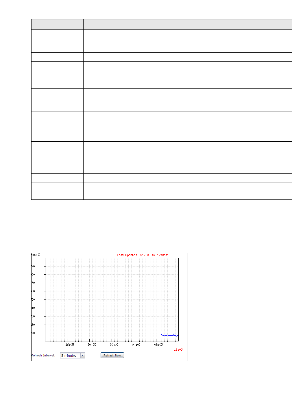
Figure 28 Dashboard > CPU Usage
WLAN Interface
Status Summary
This displays status information for the WLAN interface.
Status This displays whether or not the WLAN interface is activated.
MAC Address This displays the MAC address of the radio.
Radio This indicates the radio number on the NWA/WAC.
Band This indicates the wireless frequency band currently being used by the radio.
This shows - when the radio is in monitor mode.
OP Mode This indicates the radio’s operating mode. Operating modes are AP (MBSSID), MON
(monitor), Root AP or Repeater.
Channel This indicates the channel number the radio is using.
Antenna This indicates the antenna orientation for the radio (Wall or Ceiling).
This field is not available if the NWA/WAC does not allow you to adjust antenna orientation
for each radio using the web configurator or a physical switch. Refer to Table 1 on page 13
and Table 3 on page 15 to see if your NWA/WAC has an antenna switch.
Station This displays the number of wireless clients connected to the NWA/WAC.
AP Information This shows a summary of connected wireless Access Points (APs).
All Sensed Device This sections displays a summary of all wireless devices detected by the network. Click the
link to go to the Monitor > Wireless > Detected Device screen.
Un-Classified AP This displays the number of detected unclassified APs.
Rogue AP This displays the number of detected rogue APs.
Friendly AP This displays the number of detected friendly APs.
Table 23 Dashboard (continued)
LABEL DESCRIPTION
Chapter 4 Dashboard
NWA / WAC Series User’s Guide
59
The following table describes the labels in this screen.
4.2.2 Memory Usage
Use this screen to look at a chart of the NWA/WAC’s recent memory (RAM) usage. To access this screen,
click Memory Usage in the dashboard.
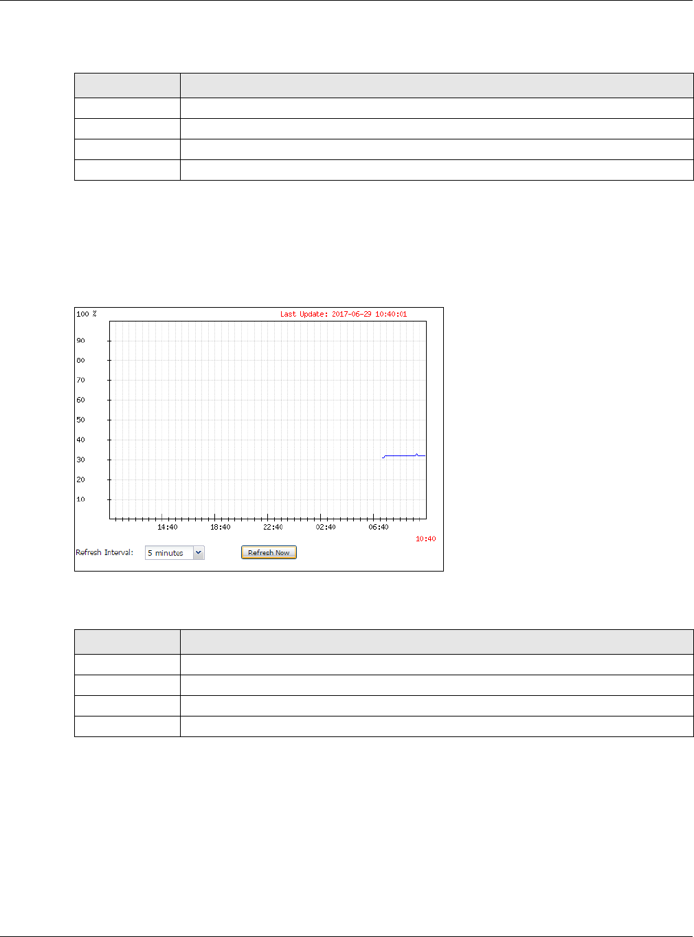
Figure 29 Dashboard > Memory Usage
The following table describes the labels in this screen.
Table 24 Dashboard > CPU Usage
LABEL DESCRIPTION
% The y-axis represents the percentage of CPU usage.
time The x-axis shows the time period over which the CPU usage occurred
Refresh Interval Enter how often you want this window to be automatically updated.
Refresh Now Click this to update the information in the window right away.
Table 25 Dashboard > Memory Usage
LABEL DESCRIPTION
% The y-axis represents the percentage of RAM usage.
time The x-axis shows the time period over which the RAM usage occurred
Refresh Interval Enter how often you want this window to be automatically updated.
Refresh Now Click this to update the information in the window right away.

NWA / WAC Series User’s Guide
60
CHAPTER 5
Monitor
5.1 Overview
Use the Monitor screens to check status and statistics information.
5.1.1 What You Can Do in this Chapter
• The Network Status screen (Section 5.3 on page 61) displays general LAN interface information and
packet statistics.
• The AP Information > Radio List screen (Section 5.4 on page 64) displays statistics about the wireless
radio transmitters in the NWA/WAC.
• The Station Info screen (Section 5.5 on page 67) displays statistics pertaining to the associated
stations.
• The WDS Link Info screen (Section 5.6 on page 68) displays statistics about the NWA/WAC’s WDS
(Wireless Distribution System) connections.
• The Detected Device screen (Section 5.7 on page 69) displays information about suspected rogue
APs.
• The View Log screen (Section 5.8 on page 72) displays the NWA/WAC’s current log messages. You
can change the way the log is displayed, you can e-mail the log, and you can also clear the log in
this screen.
5.2 What You Need to Know
The following terms and concepts may help as you read through the chapter.
Rogue AP
Rogue APs are wireless access points operating in a network’s coverage area that are not under the
control of the network’s administrators, and can open up holes in a network’s security. See Chapter 11
on page 126 for details.
Friendly AP
Friendly APs are other wireless access points that are detected in your network, as well as any others that
you know are not a threat (those from neighboring networks, for example). See Chapter 11 on page 126
for details.
Chapter 5 Monitor
NWA / WAC Series User’s Guide
61
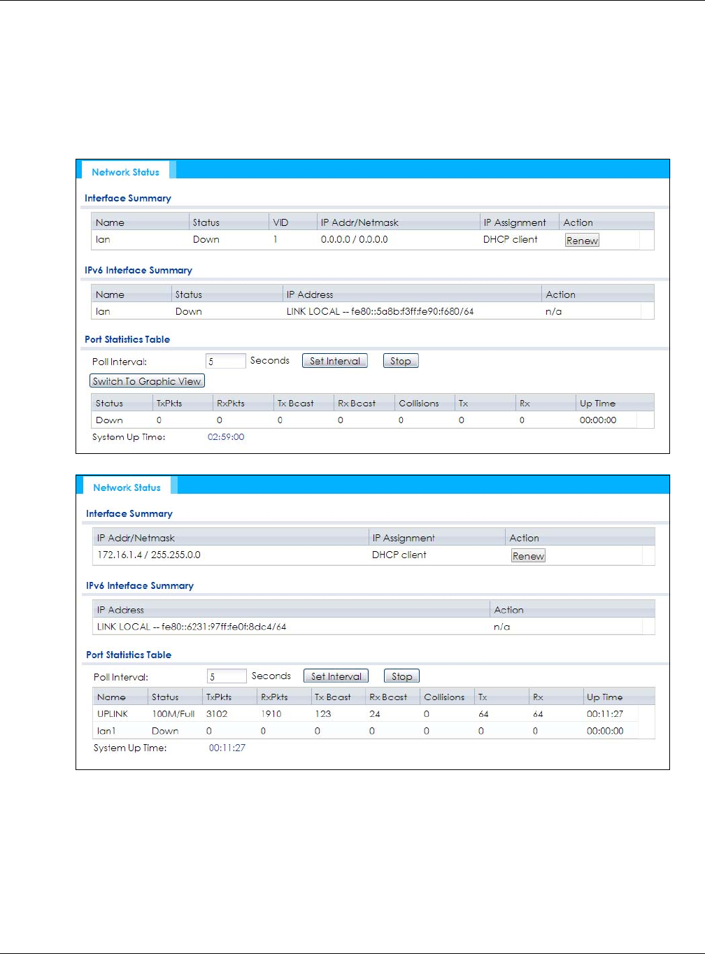
5.3 Network Status
Use this screen to look at general Ethernet interface information and packet statistics. To access this
screen, click Monitor > Network Status. The screen varies depending on whether the NWA/WAC has an
extra Ethernet port (except the uplink port).
Figure 30 Monitor > Network Status (for NWA/WAC with one Ethernet port)
Figure 31 Monitor > Network Status (for NWA/WAC with multiple Ethernet ports)

Chapter 5 Monitor
NWA / WAC Series User’s Guide
62
The following table describes the labels in this screen.
Table 26 Monitor > Network Status
LABEL DESCRIPTION
Interface
Summary
IPv6 Interface
Summary
Use the Interface Summary section for IPv4 network settings. Use the IPv6 Interface Summary
section for IPv6 network settings if you connect your NWA/WAC to an IPv6 network. Both
sections have similar fields as described below.
Name This field displays the name of the physical Ethernet port on the NWA/WAC.
Status This field displays the current status of each physical port on the NWA/WAC.
Down - The port is not connected.
Speed / Duplex - The port is connected. This field displays the port speed and duplex setting
(Full or Half).
VID This field displays the VLAN ID to which the port belongs.
IP Addr/Netmask
IP Address
This field displays the current IP address (and subnet mask) of the interface. If the IP address is
0.0.0.0 (in the IPv4 network) or :: (in the IPv6 network), the interface does not have an IP address
yet.
IP Assignment This field displays how the interface gets its IPv4 address.
Static - This interface has a static IPv4 address.
DHCP Client - This interface gets its IPv4 address from a DHCP server.
Action Use this field to get or to update the IP address for the interface. Click Renew to send a new
DHCP request to a DHCP server. If the interface cannot use one of these ways to get or to
update its IP address, this field displays n/a.
Port Statistics
Table
Poll Interval Enter how often you want this window to be updated automatically, and click Set Interval.
Set Interval Click this to set the Poll Interval the screen uses.
Stop Click this to stop the window from updating automatically. You can start it again by setting the
Poll Interval and clicking Set Interval.
Switch to Graphic
View
Click this to display the port statistics as a line graph.
Name This field displays the name of the interface.
Status This field displays the current status of the physical port.
Down - The physical port is not connected.
Speed / Duplex - The physical port is connected. This field displays the port speed and duplex
setting (Full or Half).
TxPkts This field displays the number of packets transmitted from the NWA/WAC on the physical port
since it was last connected.
RxPkts This field displays the number of packets received by the NWA/WAC on the physical port since
it was last connected.
Tx Bcast This field displays the number of broadcast packets transmitted from the NWA/WAC on the
physical port since it was last connected.
Rx Bcast This field displays the number of broadcast packets received by the NWA/WAC on the physical
port since it was last connected.
Collisions This field displays the number of collisions on the physical port since it was last connected.
Tx This field displays the transmission speed, in bytes per second, on the physical port in the one-
second interval before the screen updated.
Chapter 5 Monitor
NWA / WAC Series User’s Guide
63
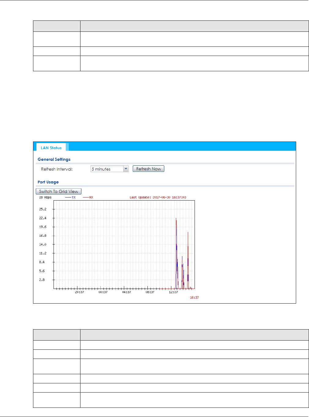
5.3.1 Port Statistics Graph
Use the port statistics graph to look at a line graph of packet statistics for the Ethernet port. To view, click
Monitor > Network Status and then the Switch to Graphic View button.
This screen is NOT available on the NWA/WAC that has an extra Ethernet port (except the uplink port).
Figure 32 Monitor > Network Status > Switch to Graphic View
The following table describes the labels in this screen.
Rx This field displays the reception speed, in bytes per second, on the physical port in the one-
second interval before the screen updated.
Up Time This field displays how long the physical port has been connected.
System Up Time This field displays how long the NWA/WAC has been running since it last restarted or was turned
on.
Table 26 Monitor > Network Status (continued)
LABEL DESCRIPTION
Table 27 Monitor > Network Status > Switch to Graphic View
LABEL DESCRIPTION
Refresh Interval Enter how often you want this window to be automatically updated.
Refresh Now Click this to update the information in the window right away.
Switch to Grid
View
Click this to display the port statistics as a table.
Kbps/Mbps The y-axis represents the speed of transmission or reception.
Time The x-axis shows the time period over which the transmission or reception occurred.
TX This line represents traffic transmitted from the NWA/WAC on the physical port since it was last
connected.
Chapter 5 Monitor
NWA / WAC Series User’s Guide
64
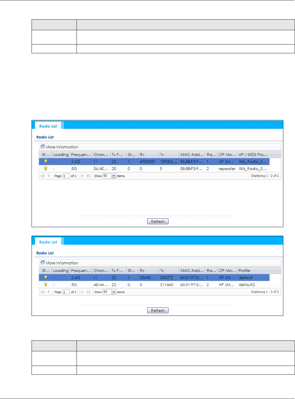
5.4 Radio List
Use this screen to view statistics for the NWA/WAC’s wireless radio transmitters. To access this screen,
click Monitor > Wireless > AP Information > Radio List.
Figure 33 Monitor > Wireless > AP Information > Radio List (for NWA/WAC that supports WDS)
Figure 34 Monitor > Wireless > AP Information > Radio List (for NWA/WAC that doesn’t support WDS)
The following table describes the labels in this screen.
RX This line represents the traffic received by the NWA/WAC on the physical port since it was last
connected.
Last Update This field displays the date and time the information in the window was last updated.
Table 27 Monitor > Network Status > Switch to Graphic View (continued)
LABEL DESCRIPTION
Table 28 Monitor > Wireless > AP Information > Radio List
LABEL DESCRIPTION
More Information Click this to view additional information about the selected radio’s wireless traffic and station
count. Information spans a 24 hour period.
Status This displays whether or not the radio is enabled.

Chapter 5 Monitor
NWA / WAC Series User’s Guide
65
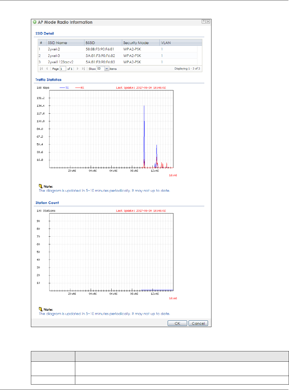
5.4.1 AP Mode Radio Information
This screen allows you to view a selected radio’s SSID details, wireless traffic statistics and station count
for the preceding 24 hours. To access this window, select a radio and click the More Information button
in the Radio List screen.
Loading This indicates the AP’s load balance status (UnderLoad or OverLoad) when load balancing is
enabled on the NWA/WAC. Otherwise, it shows - when load balancing is disabled or the radio
is in monitor mode.
MAC Address This displays the MAC address of the radio.
Radio This indicates the radio number on the NWA/WAC to which it belongs.
OP Mode This indicates the radio’s operating mode. Operating modes are AP (MBSSID), MONITOR, Root
AP or Repeater
AP/WDS Profile This indicates the AP profile name and WDS profile name to which the radio belongs.
This field is available only on the NWA/WAC that supports WDS.
Profile This indicates the AP profile name to which the radio belongs.
This field is available only on the NWA/WAC that doesn’t support WDS.
Frequency Band This indicates the wireless frequency band currently being used by the radio.
This shows - when the radio is in monitor mode.
Channel This indicates the radio’s channel ID.
Tx Power This displays the output power of the radio.
Station This displays the number of wireless clients connected to this radio on the NWA/WAC.
Rx This displays the total number of packets received by the radio.
Tx This displays the total number of packets transmitted by the radio.
Table 28 Monitor > Wireless > AP Information > Radio List (continued)
LABEL DESCRIPTION
Chapter 5 Monitor
NWA / WAC Series User’s Guide
66
Figure 35 Monitor > Wireless > AP Information > Radio List > More Information
The following table describes the labels in this screen.
Table 29 Monitor > Wireless > AP Information > Radio List > More Information
LABEL DESCRIPTION
SSID Detail This list shows information about all the wireless clients that have connected to the specified
radio over the preceding 24 hours.
# This is the items sequential number in the list. It has no bearing on the actual data in this list.
Chapter 5 Monitor
NWA / WAC Series User’s Guide
67
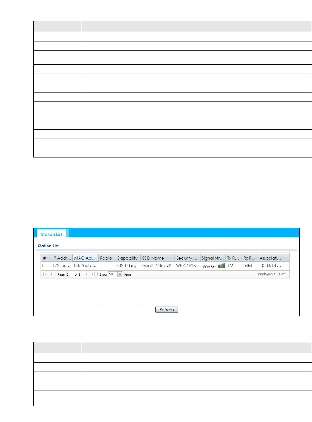
5.5 Station List
Use this screen to view statistics pertaining to the associated stations (or “wireless clients”). Click Monitor
> Wireless > Station Info to access this screen.
Figure 36 Monitor > Wireless > Station Info
The following table describes the labels in this screen.
SSID Name This displays an SSID associated with this radio. There can be up to eight maximum.
BSSID This displays a BSSID associated with this radio. The BSSID is tied to the SSID.
Security
Mode This displays the security mode in which the SSID is operating.
VLAN This displays the VLAN ID associated with the SSID.
Traffic Statistics This graph displays the overall traffic information of the radio over the preceding 24 hours.
Kbps/Mbps This y-axis represents the amount of data moved across this radio in megabytes per second.
Time This x-axis represents the amount of time over which the data moved across this radio.
Station Count This graph displays the connected station information of the radio over the preceding 24 hours
Stations The y-axis represents the number of connected stations.
Time The x-axis shows the time period over which a station was connected.
Last Update This field displays the date and time the information in the window was last updated.
OK Click this to close this window.
Cancel Click this to close this window.
Table 29 Monitor > Wireless > AP Information > Radio List > More Information (continued)
LABEL DESCRIPTION
Table 30 Monitor > Wireless > Station Info
LABEL DESCRIPTION
# This is the station’s index number in this list.
IP Address This is the station’s IP address.
MAC Address This is the station’s MAC address.
Radio This is the radio number on the NWA/WAC to which the station is connected.
Capability This displays the supported standard currently being used by the station or the standards
supported by the station.
Chapter 5 Monitor
NWA / WAC Series User’s Guide
68
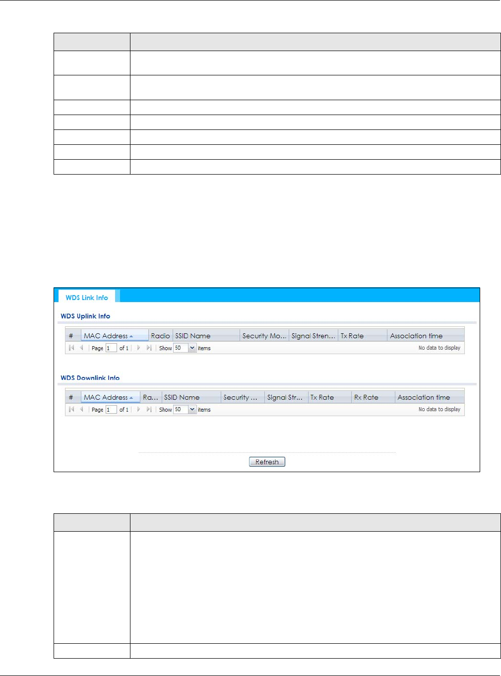
5.6 WDS Link Info
Use this screen to view the WDS traffic statistics between the NWA/WAC and a root AP or repeaters.
Click Monitor > Wireless > WDS Link Info to access this screen.
Figure 37 Monitor > Wireless > WDS Link Info
The following table describes the labels in this screen.
SSID Name This indicates the name of the wireless network to which the station is connected. A single AP
can have multiple SSIDs or networks.
Security Mode This indicates which secure encryption methods is being used by the station to connect to the
network.
Signal Strength This is the RSSI (Received Signal Strength Indicator) of the station’s wireless connection.
Tx Rate This is the maximum transmission rate of the station.
Rx Rate This is the maximum reception rate of the station.
Association Time This displays the time the station first associated with the NWA/WAC’s wireless network.
Refresh Click this to refresh the items displayed on this page.
Table 30 Monitor > Wireless > Station Info (continued)
LABEL DESCRIPTION
Table 31 Monitor > Wireless > WDS Link Info
LABEL DESCRIPTION
WDS Uplink Info
WDS Downlink
Info
Uplink refers to the WDS link from the repeaters to the root AP.
Downlink refers to the WDS link from the root AP to the repeaters.
When the NWA/WAC is in root AP mode and connected to a repeater, only the downlink
information is displayed.
When the NWA/WAC is in repeater mode and connected to a root AP directly or via another
repeater, the uplink information is displayed.
When the NWA/WAC is in repeater mode and connected to a root AP and other repeater(s),
both the uplink and downlink information would be displayed.
# This is the index number of the root AP or repeater in this list.

Chapter 5 Monitor
NWA / WAC Series User’s Guide
69
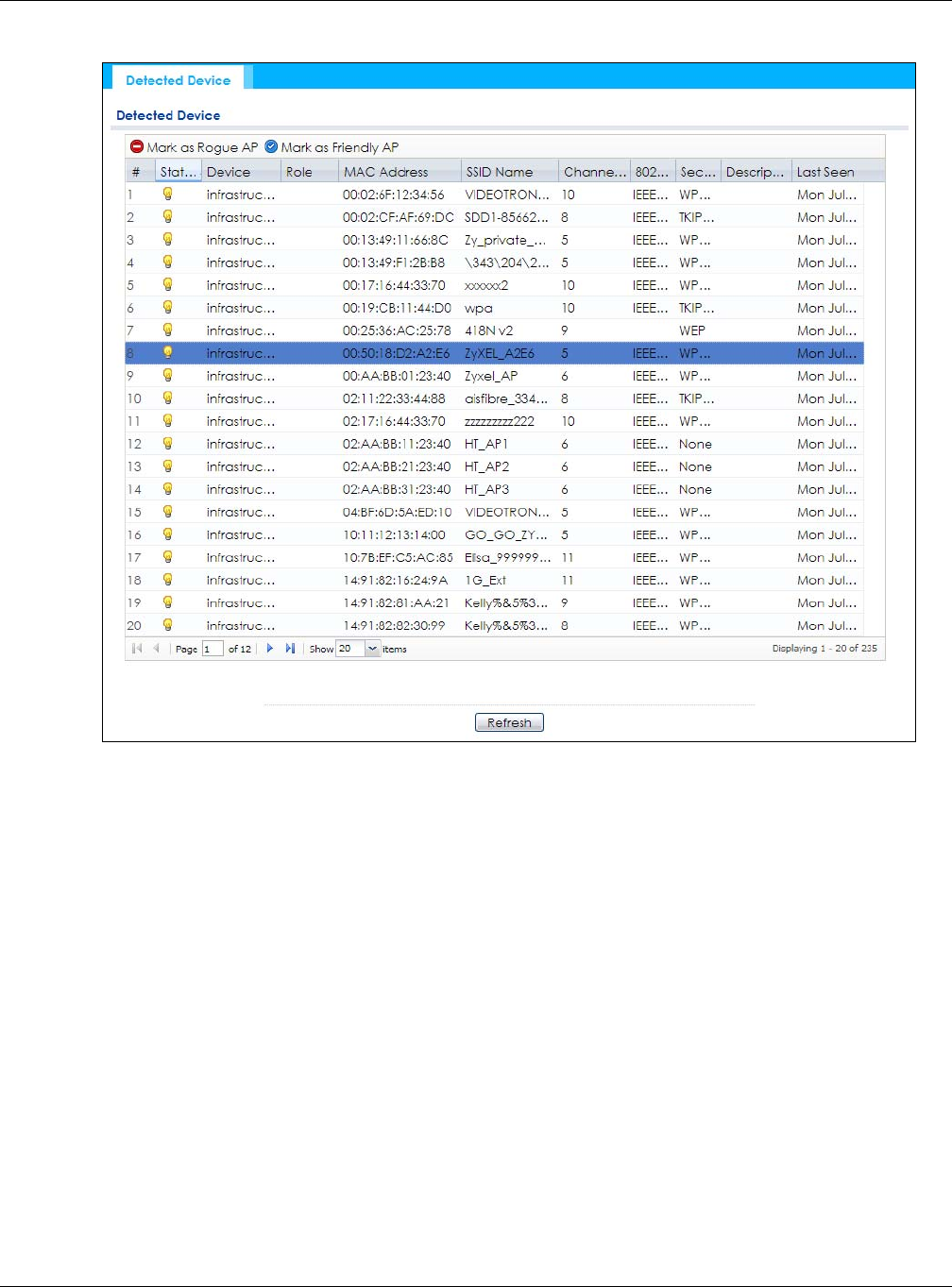
5.7 Detected Device
Use this screen to view information about suspected rogue APs. Click Monitor > Wireless > Detected
Device to access this screen. Not all NWA/WACs support monitor mode.
Note: If the NWA/WAC supports monitor mode, the radio or at least one of the NWA/WAC’s
radio must be set to monitor mode (in the Wireless > AP Management screen) in order
to detect other wireless devices in its vicinity.
If the NWA/WAC doesn’t support monitor mode, turn on rogue AP detection in the
Configuration > Wireless > Rogue AP screen to detect rogue APs.
MAC Address This is the MAC address of the root AP or repeater to which the NWA/WAC is connected using
WDS.
Radio This is the radio number on the root AP or repeater to which the NWA/WAC is connected using
WDS.
SSID Name This indicates the name of the wireless network to which the NWA/WAC is connected using
WDS.
Security Mode This indicates which secure encryption methods is being used by the NWA/WAC to connect to
the root AP or repeater using WDS.
Signal Strength This is the RSSI (Received Signal Strength Indicator) of the wireless connection in WDS.
Tx Rate This is the maximum transmission rate of the root AP or repeater to which the NWA/WAC is
connected using WDS.
Rx Rate This is the maximum reception rate of the root AP or repeater to which the NWA/WAC is
connected using WDS.
Association Time This displays the time the NWA/WAC first associated with the wireless network using WDS.
Refresh Click this to refresh the items displayed on this page.
Table 31 Monitor > Wireless > WDS Link Info (continued)
LABEL DESCRIPTION
Chapter 5 Monitor
NWA / WAC Series User’s Guide
70
Figure 38 Monitor > Wireless > Detected Device (for NWA/WAC that supports Monitor mode)
Chapter 5 Monitor
NWA / WAC Series User’s Guide
71
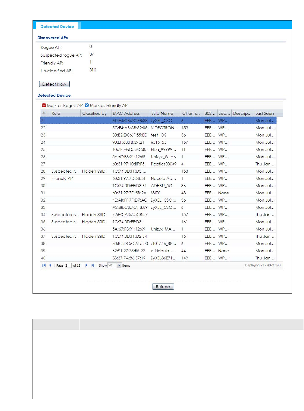
Figure 39 Monitor > Wireless > Detected Device (for NWA/WAC that doesn’t support Monitor mode)
The following table describes the labels in this screen.
Table 32 Monitor > Wireless > Detected Device
LABEL DESCRIPTION
Discovered APs
Rogue AP This shows how many devices are detected as rogue APs.
Suspected rogue
AP
This shows how many devices are detected as possible rogue APs by classification rule.
Friendly AP This shows how many devices are detected as friendly APs.
Un-classified AP This shows how many devices are detected, but have not been classified by the NWA/WAC.
Detect Now Click this button for the NWA/WAC to scan for APs in the network.
Detected Device

Chapter 5 Monitor
NWA / WAC Series User’s Guide
72
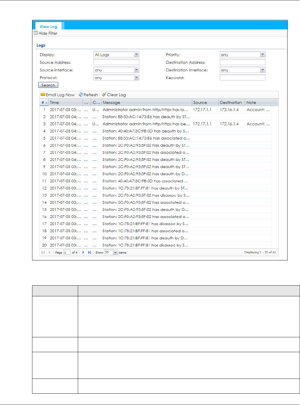
5.8 View Log
Log messages are stored in two separate logs, one for regular log messages and one for debugging
messages. In the regular log, you can look at all the log messages by selecting All Logs, or you can
select a specific category of log messages (for example, user). You can also look at the debugging log
by selecting Debug Log. All debugging messages have the same priority.
To access this screen, click Monitor > Log. The log is displayed in the following screen.
Note: When a log reaches the maximum number of log messages, new log messages
automatically overwrite existing log messages, starting with the oldest existing log
message first.
Events that generate an alert (as well as a log message) display in red. Regular logs display in black.
Click a column’s heading cell to sort the table entries by that column’s criteria. Click the heading cell
again to reverse the sort order.
Mark as Rogue
AP
Click this button to mark the selected AP as a rogue AP. A rogue AP can be contained in the
Configuration > Wireless > Rogue AP screen (Section 7.3 on page 88).
Mark as Friendly
AP
Click this button to mark the selected AP as a friendly AP. For more on managing friendly APs,
see the Configuration > Wireless > Rogue AP screen (Section 7.3 on page 88).
# This is the detected device’s index number in this list.
Status This indicates the detected device’s status.
Device This indicates the type of device detected.
Role This indicates the detected device’s role (such as friendly or rogue).
Classified by This indicates the detected device’s classification rule.
MAC Address This indicates the detected device’s MAC address.
SSID Name This indicates the detected device’s SSID.
Channel ID This indicates the detected device’s channel ID.
802.11 Mode This indicates the 802.11 mode (a/b/g/n) transmitted by the detected device.
Security This indicates the encryption method (if any) used by the detected device.
Description This displays the detected device’s description. For more on managing friendly and rogue APs,
see the Configuration > Wireless > Rogue AP screen (Section 7.3 on page 88).
Last Seen This indicates the last time the device was detected by the NWA/WAC.
Refresh Click this to refresh the items displayed on this page.
Table 32 Monitor > Wireless > Detected Device (continued)
LABEL DESCRIPTION
Chapter 5 Monitor
NWA / WAC Series User’s Guide
73
Figure 40 Monitor > Log > View Log
The following table describes the labels in this screen.
Table 33 Monitor > Log > View Log
LABEL DESCRIPTION
Show Filter / Hide
Filter
Click this button to show or hide the filter settings.
If the filter settings are hidden, the Display, Email Log Now, Refresh, and Clear Log fields are
available.
If the filter settings are shown, the Display, Priority, Source Address, Destination Address, Source
Interface, Destination Interface, Protocol, Keyword, and Search fields are available.
Display Select the category of log message(s) you want to view. You can also view All Logs at one
time, or you can view the Debug Log.
Priority This displays when you show the filter. Select the priority of log messages to display. The log
displays the log messages with this priority or higher. Choices are: any, emerg, alert, crit, error,
warn, notice, and info, from highest priority to lowest priority. This field is read-only if the
Category is Debug Log.
Source Address This displays when you show the filter. Type the source IP address of the incoming packet that
generated the log message. Do not include the port in this filter.

Chapter 5 Monitor
NWA / WAC Series User’s Guide
74
The Web Configurator saves the filter settings if you leave the View Log screen and return to it later.
Destination
Address
This displays when you show the filter. Type the IP address of the destination of the incoming
packet when the log message was generated. Do not include the port in this filter.
Source Interface This displays when you show the filter. Select the source interface of the packet that generated
the log message.
Destination
Interface
This displays when you show the filter. Select the destination interface of the packet that
generated the log message.
Protocol This displays when you show the filter. Select a service protocol whose log messages you would
like to see.
Keyword This displays when you show the filter. Type a keyword to look for in the Message, Source,
Destination and Note fields. If a match is found in any field, the log message is displayed. You
can use up to 63 alphanumeric characters and the underscore, as well as punctuation marks
()’ ,:;?! +-*/= #$% @ ; the period, double quotes, and brackets are not allowed.
Search This displays when you show the filter. Click this button to update the log using the current filter
settings.
Email Log Now Click this button to send log messages to the Active e-mail addresses specified in the Send Log
To field on the Configuration > Log & Report > Log Settings screen.
Refresh Click this to update the list of logs.
Clear Log Click this button to clear the whole log, regardless of what is currently displayed on the screen.
#This field is a sequential value, and it is not associated with a specific log message.
Time This field displays the time the log message was recorded.
Priority This field displays the priority of the log message. It has the same range of values as the Priority
field above.
Category This field displays the log that generated the log message. It is the same value used in the
Display and (other) Category fields.
Message This field displays the reason the log message was generated. The text “[count=x]”, where x is a
number, appears at the end of the Message field if log consolidation is turned on and multiple
entries were aggregated to generate into this one.
Source This field displays the source IP address and the port number in the event that generated the
log message.
Source Interface This field displays the source interface of the packet that generated the log message.
Destination This field displays the destination IP address and the port number of the event that generated
the log message.
Destination
Interface
This field displays the destination interface of the packet that generated the log message.
Protocol This field displays the service protocol in the event that generated the log message.
Note This field displays any additional information about the log message.
Table 33 Monitor > Log > View Log (continued)
LABEL DESCRIPTION
NWA / WAC Series User’s Guide
75
CHAPTER 6
Network
6.1 Overview
This chapter describes how you can configure the management IP address and VLAN settings of your
NWA/WAC.
The Internet Protocol (IP) address identifies a device on a network. Every networking device (including
computers, servers, routers, printers, etc.) needs an IP address to communicate across the network.
These networking devices are also known as hosts.
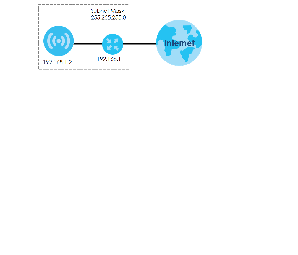
Figure 41 IP Setup
The figure above illustrates one possible setup of your NWA/WAC. The gateway IP address is 192.168.1.1
and the managed IP address of the NWA/WAC is 192.168.1.2 (default), but if the NWA/WAC is assigned
an IP address by a DHCP server, the default (192.168.1.2) will not be used. The gateway and the NWA/
WAC must belong in the same IP subnet to be able to communicate with each other.
6.1.1 Management Mode
This discusses using the NWA/WAC in management mode, which determines whether the NWA/WAC is
used in its standalone mode, or as part of a Control And Provisioning of Wireless Access Points (CAPWAP)
network.
About CAPWAP
The NWA/WAC supports CAPWAP. This is Zyxel’s implementation of the CAPWAP protocol (RFC 5415).
The CAPWAP data flow is protected by Datagram Transport Layer Security (DTLS).
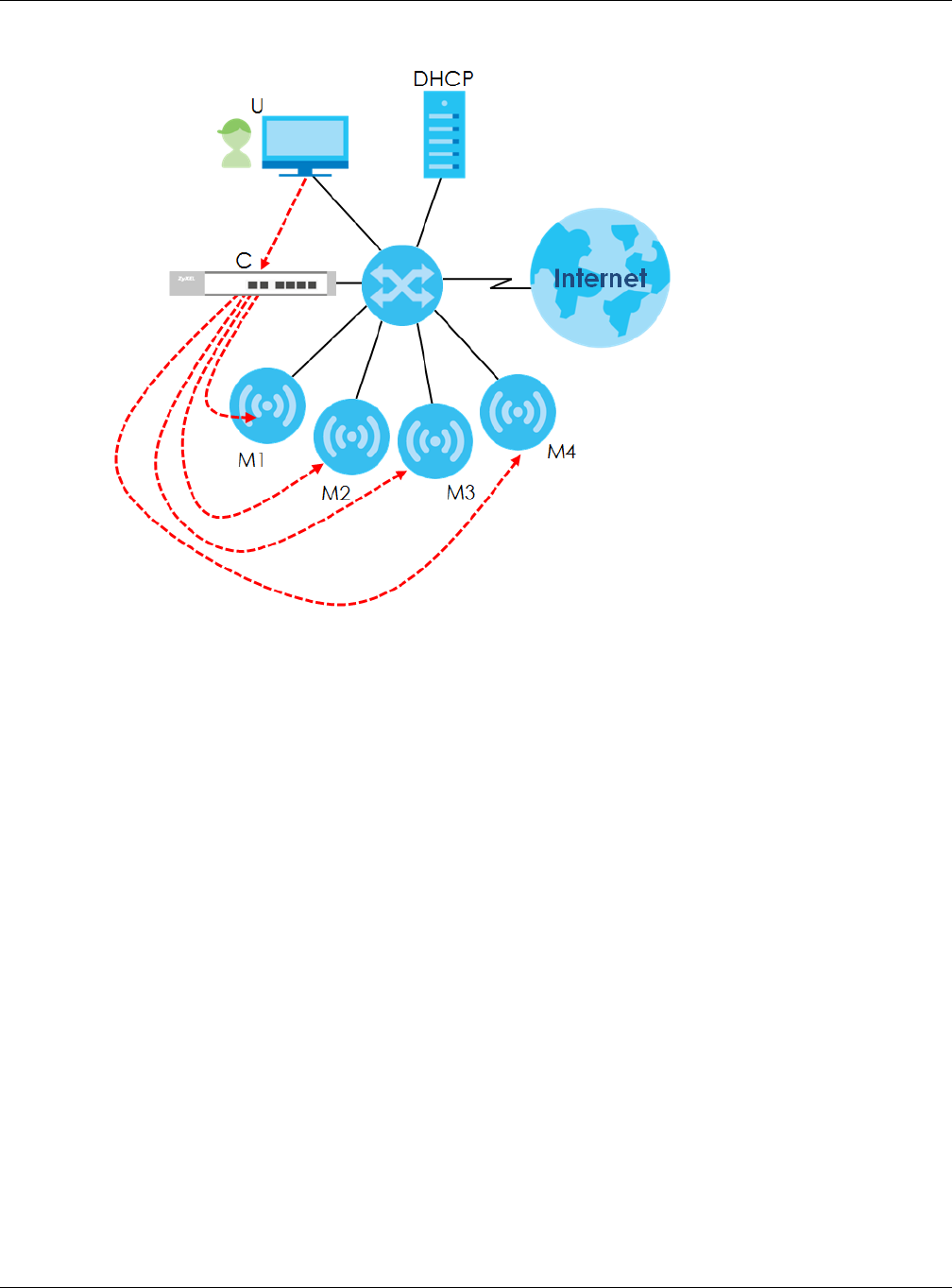
The following figure illustrates a CAPWAP wireless network. You (U) configure the AP controller (C), which
then automatically updates the configurations of the managed APs (M1 ~ M4).
Chapter 6 Network
NWA / WAC Series User’s Guide
76
Figure 42 CAPWAP Network Example
Note: The NWA/WAC can be a standalone AP (default), or a CAPWAP managed AP.
CAPWAP Discovery and Management
The link between CAPWAP-enabled access points proceeds as follows:
1An AP in managed AP mode joins a wired network (receives a dynamic IP address).
2The AP sends out a discovery request, looking for a CAPWAP AP controller.
3If there is an AP controller on the network, it receives the discovery request. If the AP controller is in
Manual mode it adds the details of the AP to its Unmanaged Access Points list, and you decide which
available APs to manage. If the AP controller is in Always Accept mode, it automatically adds the AP to
its Managed Access Points list and provides the managed AP with default configuration information, as
well as securely transmitting the DTLS pre-shared key. The managed AP is ready for association with
wireless clients.
Managed AP Finds the Controller
A managed NWA/WAC can find the controller in one of the following ways:
• Manually specify the controller’s IP address in the Web Configurator’s AC (AP Controller) Discovery
screen.
• Get the controller’s IP address from a DHCP server with the controller’s IP address configured as
option 138.
• Get the controller’s IP address from a DNS server SRV (Service) record.
Chapter 6 Network
NWA / WAC Series User’s Guide
77
• Broadcasting to discover the controller within the broadcast domain.
Note: The AP controller needs to have a static IP address. If it is a DHCP client, set the DHCP
server to reserve an IP address for the AP controller.
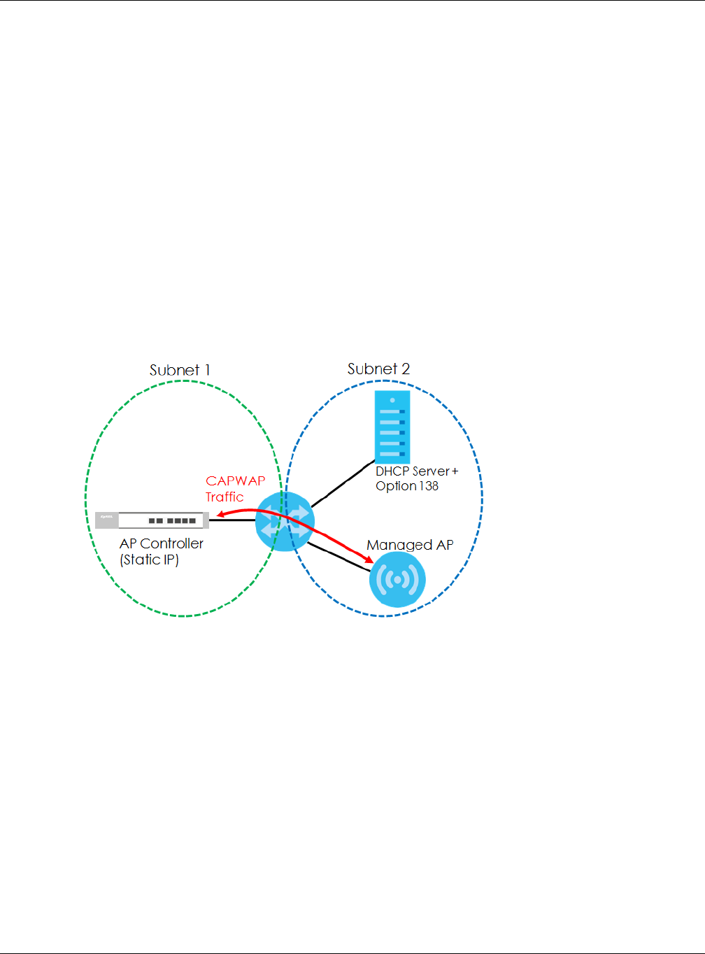
CAPWAP and IP Subnets
By default, CAPWAP works only between devices with IP addresses in the same subnet.
However, you can configure CAPWAP to operate between devices with IP addresses in different
subnets by doing the following.
• Activate DHCP. Your network’s DHCP server must support option 138 defined in RFC 5415.
• Configure DHCP option 138 with the IP address of the CAPWAP AP controller on your network.
DHCP Option 138 allows the CAPWAP management request (from the AP in managed AP mode) to
reach the AP controller in a different subnet, as shown in the following figure.
Figure 43 CAPWAP and DHCP Option 138
Notes on CAPWAP
This section lists some additional features of Zyxel’s implementation of the CAPWAP protocol.
• When the AP controller uses its internal Remote Authentication Dial In User Service (RADIUS) server,
managed APs also use the AP controller’s authentication server to authenticate wireless clients.
• If a managed AP’s link to the AP controller is broken, the managed AP continues to use the wireless
settings with which it was last provided.
6.1.2 What You Can Do in this Chapter
• The IP Setting screen (Section 6.2 on page 78) configures the NWA/WAC’s LAN IP address.
• The VLAN screen (Section 6.3 on page 79) configures the NWA/WAC’s VLAN settings.
• The AC (AP Controller) Discovery screen (Section 6.3 on page 79) configures the NWA/WAC’s AP
Controller settings.
Chapter 6 Network
NWA / WAC Series User’s Guide
78
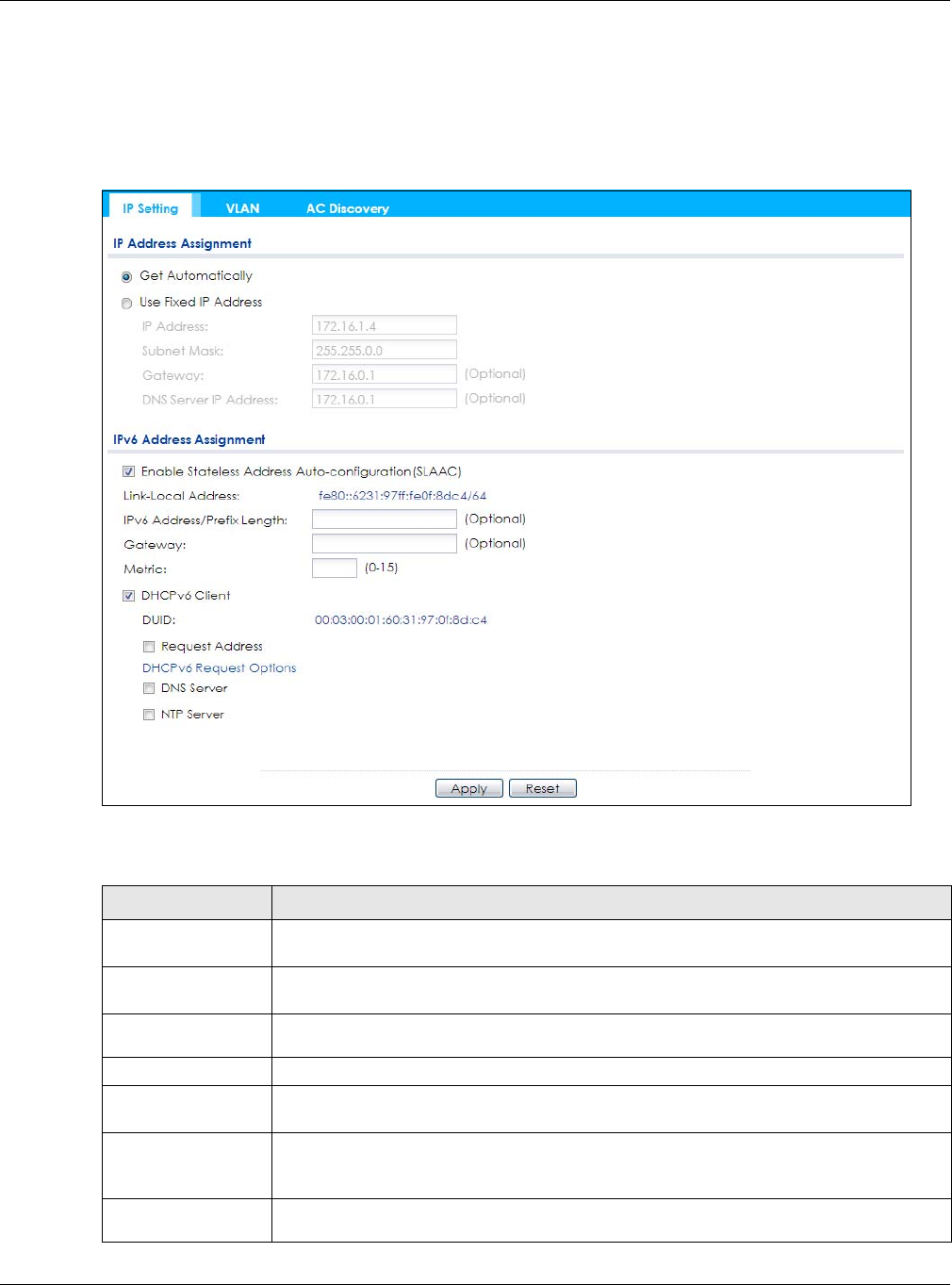
6.2 IP Setting
Use this screen to configure the IP address for your NWA/WAC. To access this screen, click Configuration
> Network > IP Setting.
Figure 44 Configuration > Network > IP Setting
Each field is described in the following table.
Table 34 Configuration > Network > IP Setting
LABEL DESCRIPTION
IP Address
Assignment
Get
Automatically Select this to make the interface a DHCP client and automatically get the IP address,
subnet mask, and gateway address from a DHCP server.
Use Fixed IP
Address Select this if you want to specify the IP address, subnet mask, and gateway manually.
IP Address Enter the IP address for this interface.
Subnet Mask Enter the subnet mask of this interface in dot decimal notation. The subnet mask indicates
what part of the IP address is the same for all computers in the network.
Gateway Enter the IP address of the gateway. The NWA/WAC sends packets to the gateway when it
does not know how to route the packet to its destination. The gateway should be on the
same network as the interface.
DNS Server IP
Address Enter the IP address of the DNS server.

Chapter 6 Network
NWA / WAC Series User’s Guide
79
6.3 VLAN
This section discusses how to configure the NWA/WAC’s VLAN settings.
IPv6 Address
Assignment
Enable Stateless
Address Auto-
configuration
(SLAAC)
Select this to enable IPv6 stateless auto-configuration on the NWA/WAC. The NWA/WAC will
generate an IPv6 address itself from a prefix obtained from an IPv6 router in the network.
Link-Local
Address This displays the IPv6 link-local address and the network prefix that the NWA/WAC
generates itself for the LAN interface.
IPv6 Address/
Prefix Length Enter the IPv6 address and the prefix length for the LAN interface if you want to use a static
IP address. This field is optional.
The prefix length indicates what the left-most part of the IP address is the same for all
computers in the network, that is, the network address.
Gateway Enter the IPv6 address of the default outgoing gateway using colon (:) hexadecimal
notation.
Metric Enter the priority of the gateway (if any) on the LAN interface. The NWA/WAC decides
which gateway to use based on this priority. The lower the number, the higher the priority. If
two or more gateways have the same priority, the NWA/WAC uses the one that was
configured first. Enter zero to set the metric to 1024 for IPv6.
DHCPv6 Client Select this option to set the NWA/WAC to act as a DHCPv6 client.
DUID This field displays the DHCP Unique IDentifier (DUID) of the NWA/WAC, which is unique and
used for identification purposes when the NWA/WAC is exchanging DHCPv6 messages with
others. See Appendix B on page 227 for more information.
Request Address Select this option to get an IPv6 address from the DHCPv6 server.
DHCPv6 Request
Options
Select this option to determine what additional information to get from the DHCPv6 server.
DNS Server Select this option to obtain the IP address of the DNS server.
NTP Server Select this option to obtain the IP address of the NTP server.
Apply Click Apply to save your changes back to the NWA/WAC.
Reset Click Reset to return the screen to its last-saved settings.
Table 34 Configuration > Network > IP Setting (continued)
LABEL DESCRIPTION
Chapter 6 Network
NWA / WAC Series User’s Guide
80
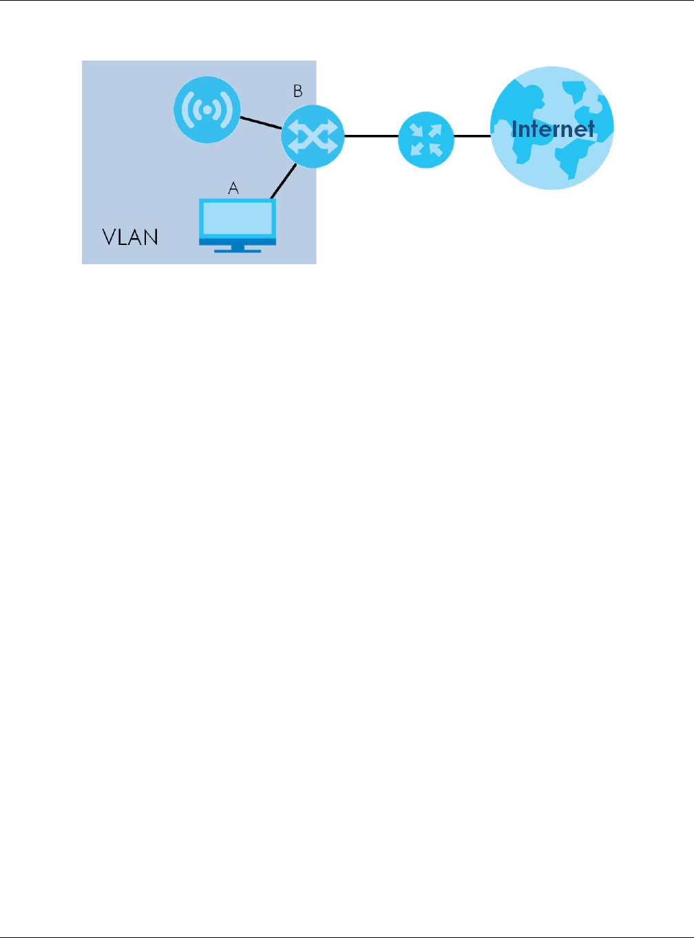
Figure 45 Management VLAN Setup
In the figure above, to access and manage the NWA/WAC from computer A, the NWA/WAC and
switch B’s ports to which computer A and the NWA/WAC are connected should be in the same VLAN.
A Virtual Local Area Network (VLAN) allows a physical network to be partitioned into multiple logical
networks. Devices on a logical network belong to one group. A device can belong to more than one
group. With VLAN, a device cannot directly talk to or hear from devices that are not in the same
group(s); the traffic must first go through a router.
VLAN also increases network performance by limiting broadcasts to a smaller and more manageable
logical broadcast domain. In traditional switched environments, all broadcast packets go to each and
every individual port. With VLAN, all broadcasts are confined to a specific broadcast domain.
IEEE 802.1Q Tag
The IEEE 802.1Q standard defines an explicit VLAN tag in the MAC header to identify the VLAN
membership of a frame across bridges. A VLAN tag includes the 12-bit VLAN ID and 3-bit user priority.
The VLAN ID associates a frame with a specific VLAN and provides the information that devices need to
process the frame across the network.
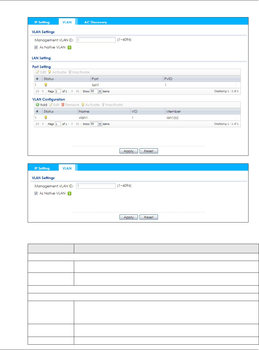
Use this screen to configure the VLAN settings for your NWA/WAC. To access this screen, click
Configuration > Network > VLAN.
The screen varies depending on whether the NWA/WAC has an extra Ethernet port (except the uplink
port).
Chapter 6 Network
NWA / WAC Series User’s Guide
81
Figure 46 Configuration > Network > VLAN (for NWA/WAC with multiple Ethernet ports)
Figure 47 Configuration > Network > VLAN (for NWA/WAC with one Ethernet port)
Each field is described in the following table.
Table 35 Configuration > Network > VLAN
LABEL DESCRIPTION
VLAN Settings
Management
VLAN ID Enter a VLAN ID for the NWA/WAC.
As Native VLAN Select this option to treat this VLAN ID as a VLAN created on the NWA/WAC and not one
assigned to it from outside the network.
LAN Setting
Port Setting
Edit Double-click an entry or select it and click Edit to open a screen where you can modify the
entry’s settings. In some tables you can just click a table entry and edit it directly in the
table. For those types of tables small red triangles display for table entries with changes that
you have not yet applied.
Activate/
Inactivate To turn on an entry, select it and click Activate. To turn off an entry, select it and click
Inactivate.
# This is the index number of the port.

Chapter 6 Network
NWA / WAC Series User’s Guide
82
6.4 AC (AP Controller) Discovery
This section discusses how to configure the NWA/WAC’s AC (AP Controller) Discovery settings. You can
have the NWA/WAC managed by an AP controller on your network. When you do this, the NWA/WAC
can be configured ONLY by the AP controller. See Section 6.1.1 on page 75 for more information on
management mode and AP Controller.
Note: The AC (AP Controller) Discovery settings are not available in all NWA/WACs. See
Section 1.1 on page 13 for more information.
If you want to return the NWA/WAC to standalone AP mode, you can do one of the two following
options:
• Press the Reset button.
• Check the AP controller for the NWA/WAC’s IP address and use FTP to upload the default
configuration file to the NWA/WAC. You can get the configuration file at conf/system-default.conf.
You must reboot the device after uploading the configuration file.
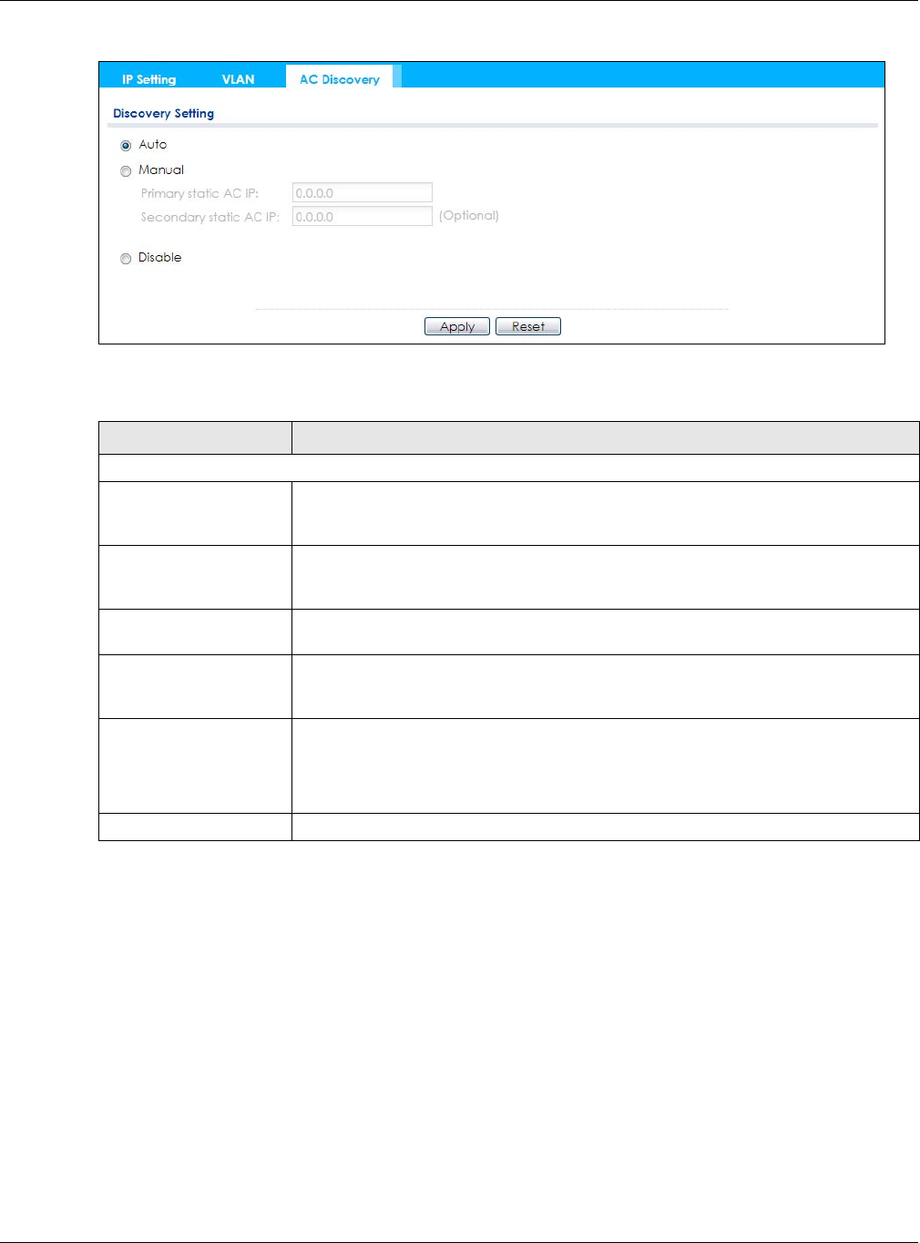
To access the Controller Discover screen, click Configuration > Network > AC Discovery.
Status This field indicates whether the port is enabled (a yellow bulb) or not (a gray bulb).
Port This field displays the name of the port.
PVID This field displays the port number of the VLAN ID.
VLAN Configuration
Add Click this to create a new entry. For features where the entry’s position in the numbered list is
important (features where the NWA/WAC applies the table’s entries in order like the SSID for
example), you can select an entry and click Add to create a new entry after the selected
entry.
Edit Double-click an entry or select it and click Edit to open a screen where you can modify the
entry’s settings. In some tables you can just click a table entry and edit it directly in the
table. For those types of tables small red triangles display for table entries with changes that
you have not yet applied.
Remove To remove an entry, select it and click Remove. The NWA/WAC confirms you want to
remove it before doing so.
Activate/
Inactivate To turn on an entry, select it and click Activate. To turn off an entry, select it and click
Inactivate.
# This is the index number of the VLAN ID
Status This field indicates whether the VLAN is enabled (a yellow bulb) or not (a gray bulb).
Name This field displays the name of each VLAN.
VID This field displays the VLAN ID.
Member This field displays the VLAN membership to which the port belongs.
Apply Click Apply to save your changes back to the NWA/WAC.
Reset Click Reset to return the screen to its last-saved settings.
Table 35 Configuration > Network > VLAN (continued)
LABEL DESCRIPTION
Chapter 6 Network
NWA / WAC Series User’s Guide
83
Figure 48 Configuration > Network > AC Discovery
Each field is described in the following table.
Table 36 Configuration > Network > AC Discovery
LABEL DESCRIPTION
Discovery Setting
Auto Select this option to use DHCP option 138/DNS SRV record/Broadcast to get the AP
controller’s IP address. If the NWA/WAC and a Zyxel AP controller, such as the NXC2500
or NXC5500, are in the same subnet, it will be managed by the controller automatically.
Manual Select this option and enter the IP address of the AP controller manually. This is
necessary when the AP Controller is not in the same subnet and you want it to manage
the NWA/WAC.
Primary / Secondary
Static AC IP Specify the primary and secondary IP address of the AP controller to which the NWA/
WAC connects.
Disable Select this to manage the NWA/WAC using its own web configurator, neither managing
nor managed by other devices. Please note if an AP Controller is in the same subnet,
you will need to click Disable if you do not want the NWA/WAC to be managed.
Apply Click Apply to save the information entered in this screen.
If you select Auto or Manual, the AP controller uploads the firmware package for
managed AP mode to the NWA/WAC and you cannot log in as the web configurator is
disabled; you must manage the NWA/WAC through the AP controller on your network.
Reset Click Reset to return the screen to its last-saved settings.
NWA / WAC Series User’s Guide
84
CHAPTER 7
Wireless
7.1 Overview
This chapter discusses how to configure the wireless network settings in your NWA/WAC.
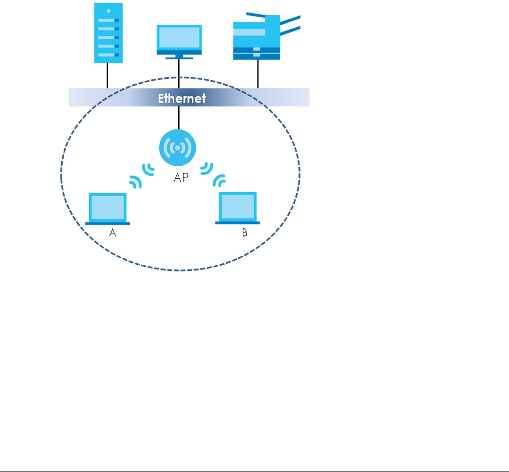
The following figure provides an example of a wireless network.
Figure 49 Example of a Wireless Network
The wireless network is the part in the blue circle. In this wireless network, devices A and B are called
wireless clients. The wireless clients use the access point (AP) to interact with other devices (such as the
printer) or with the Internet. Your NWA/WAC is the AP.
7.1.1 What You Can Do in this Chapter
• The AP Management screen (Section 7.2 on page 85) manages the NWA/WAC’s general wireless
settings.
• The Rogue AP screen (Section 7.3 on page 88) allows you to assign APs either to the rogue AP list or
the friendly AP list.
• The Load Balancing screen (Section 7.4 on page 91) configures network traffic load balancing
between the APs and the NWA/WAC.
• The DCS screen (Section 7.5 on page 94) configures dynamic radio channel selection.

Chapter 7 Wireless
NWA / WAC Series User’s Guide
85
7.1.2 What You Need to Know
The following terms and concepts may help as you read this chapter.
Station / Wireless Client
A station or wireless client is any wireless-capable device that can connect to an AP using a wireless
signal.
Dynamic Channel Selection (DCS)
Dynamic Channel Selection (DCS) is a feature that allows an AP to automatically select the radio
channel upon which it broadcasts by scanning the area around it and determining what channels are
currently being used by other devices.
Load Balancing (Wireless)
Wireless load balancing is the process where you limit the number of connections allowed on an wireless
access point (AP) or you limit the amount of wireless traffic transmitted and received on it so the AP
does not become overloaded.
7.2 AP Management
Use this screen to manage the NWA/WAC’s general wireless settings. Click Configuration > Wireless > AP
Management to access this screen.
Chapter 7 Wireless
NWA / WAC Series User’s Guide
86
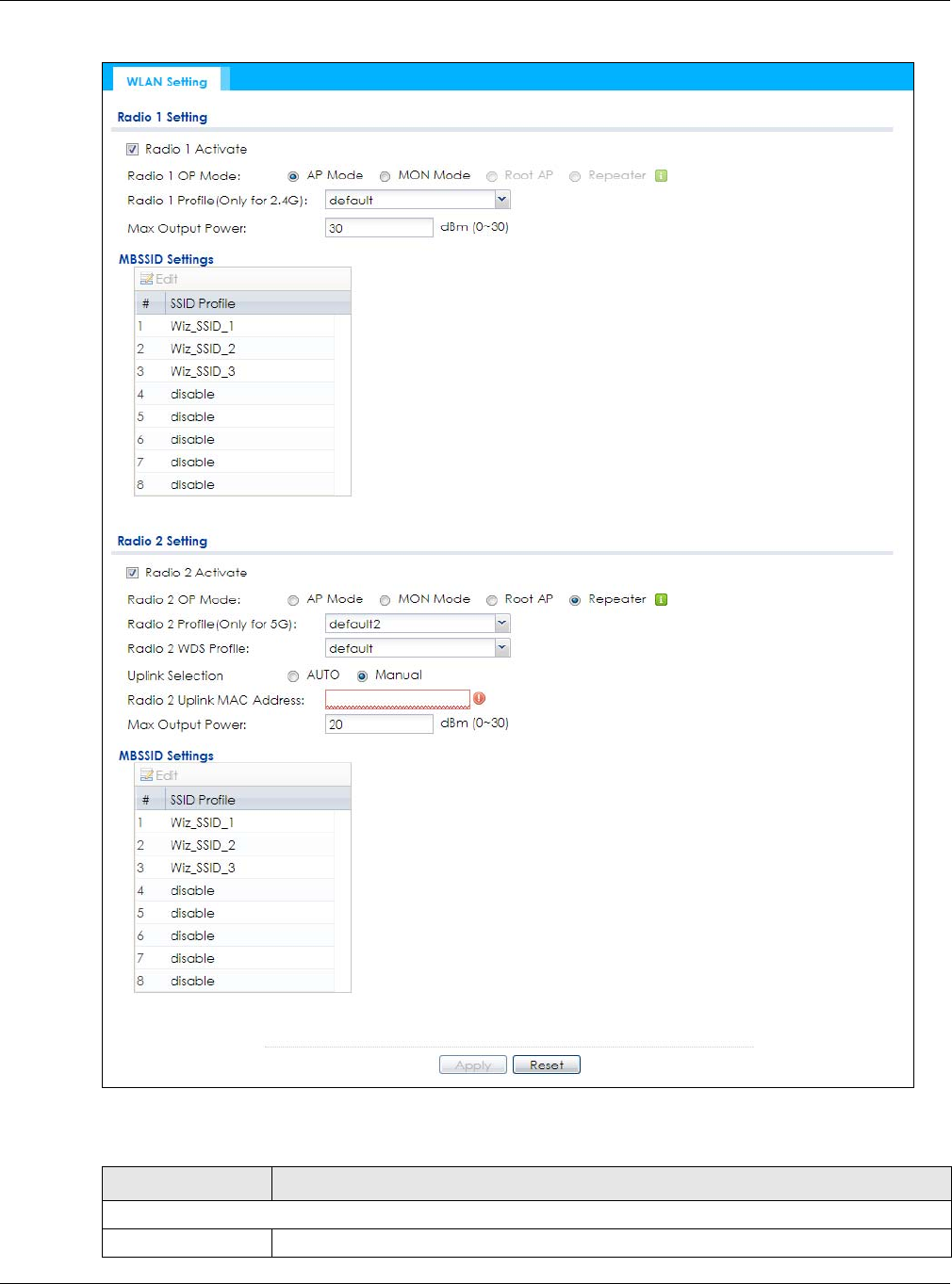
Figure 50 Configuration > Wireless > AP Management
Each field is described in the following table.
Table 37 Configuration > Wireless > AP Management
LABEL DESCRIPTION
Radio 1 Setting
Radio 1 Activate Select the check box to enable the NWA/WAC’s first (default) radio.

Chapter 7 Wireless
NWA / WAC Series User’s Guide
87
Radio 1 OP Mode Select the operating mode for radio 1.
AP Mode means the radio can receive connections from wireless clients and pass their data
traffic through to the NWA/WAC to be managed (or subsequently passed on to an
upstream gateway for managing).
MON Mode means the radio monitors the broadcast area for other APs, then passes their
information on to the NWA/WAC where it can be determined if those APs are friendly or
rogue. If a radio is set to this mode it cannot receive connections from wireless clients.
Root AP means the radio acts as an AP and also supports the wireless connections with
other APs (in repeater mode) to form a WDS (Wireless Distribution System) to extend its
wireless network.
Repeater means the radio can establish a wireless connection with other APs (in either root
AP or repeater mode) to form a WDS.
Radio 1 Profile Select the radio profile the radio uses.
Note: You can only apply a 2.4G AP radio profile to radio 1. Otherwise, the first
radio will not be working.
Radio 1 WDS Profile This field is available only when the radio is in Root AP or Repeater mode.
Select the WDS profile the radio uses to connect to a root AP or repeater.
Uplink Selection
Mode
This field is available only when the radio is in Repeater mode.
Select AUTO to have the NWA/WAC automatically use the settings in the applied WDS
profile to connect to a root AP or repeater.
Select Manual to have the NWA/WAC connect to the root AP or repeater with the MAC
address specified in the Radio 1 Uplink MAC Address field.
Max Output Power Enter the maximum output power (between 0 to 30 dBm) of the NWA/WAC in this field. If
there is a high density of APs in an area, decrease the output power of the NWA/WAC to
reduce interference with other APs.
Note: Reducing the output power also reduces the NWA/WAC’s effective
broadcast radius.
MBSSID Settings
Edit Double-click an entry or select it and click Edit to open a screen where you can modify the
entry’s settings. In some tables you can just click a table entry and edit it directly in the
table. For those types of tables small red triangles display for table entries with changes that
you have not yet applied.
# This field shows the index number of the SSID
SSID Profile This field displays the SSID profile that is associated with the radio profile.
Radio 2 Setting
Radio 2 Activate This displays if the NWA/WAC has a second radio.
Select the check box to enable the NWA/WAC’s second radio.
Table 37 Configuration > Wireless > AP Management (continued)
LABEL DESCRIPTION

Chapter 7 Wireless
NWA / WAC Series User’s Guide
88
7.3 Rogue AP
Use this screen to assign APs either to the rogue AP list or the friendly AP list. A rogue AP is a wireless
access point operating in a network’s coverage area that is not under the control of the network
administrator, and which can potentially open up holes in a network’s security.
Click Configuration > Wireless > Rogue AP to access this screen.
Radio 2 OP Mode This displays if the NWA/WAC has a second radio. Select the operating mode for radio 2.
AP Mode means the radio can receive connections from wireless clients and pass their data
traffic through to the NWA/WAC to be managed (or subsequently passed on to an
upstream gateway for managing).
MON Mode means the radio monitors the broadcast area for other APs, then passes their
information on to the NWA/WAC where it can be determined if those APs are friendly or
rogue. If a radio is set to this mode it cannot receive connections from wireless clients.
Root AP means the radio acts as an AP and also supports the wireless connections with
other APs (in repeater mode) to form a WDS to extend its wireless network.
Repeater means the radio can establish a wireless connection with other APs (in either root
AP or repeater mode) to form a WDS.
Radio 2 Profile This displays if the NWA/WAC has a second radio. Select the radio profile the radio uses.
Note: You can only apply a 5G AP radio profile to radio 2. Otherwise, the second
radio will not be working.
Radio 2 WDS Profile This field is available only when the radio is in Root AP or Repeater mode.
Select the WDS profile the radio uses to connect to a root AP or repeater.
Uplink Selection
Mode
This field is available only when the radio is in Repeater mode.
Select AUTO to have the NWA/WAC automatically use the settings in the applied WDS
profile to connect to a root AP or repeater.
Select Manual to have the NWA/WAC connect to the root AP or repeater with tbe MAC
address specified in the Radio 2 Uplink MAC Address field.
Max Output Power Enter the maximum output power (between 0 to 30 dBm) of the NWA/WAC in this field. If
there is a high density of APs in an area, decrease the output power of the NWA/WAC to
reduce interference with other APs.
Note: Reducing the output power also reduces the NWA/WAC’s effective
broadcast radius.
MBSSID Settings
Edit Double-click an entry or select it and click Edit to open a screen where you can modify the
entry’s settings. In some tables you can just click a table entry and edit it directly in the
table. For those types of tables small red triangles display for table entries with changes that
you have not yet applied.
# This field shows the index number of the SSID
SSID Profile This field shows the SSID profile that is associated with the radio profile.
Apply Click Apply to save your changes back to the NWA/WAC.
Reset Click Reset to return the screen to its last-saved settings.
Table 37 Configuration > Wireless > AP Management (continued)
LABEL DESCRIPTION
Chapter 7 Wireless
NWA / WAC Series User’s Guide
89
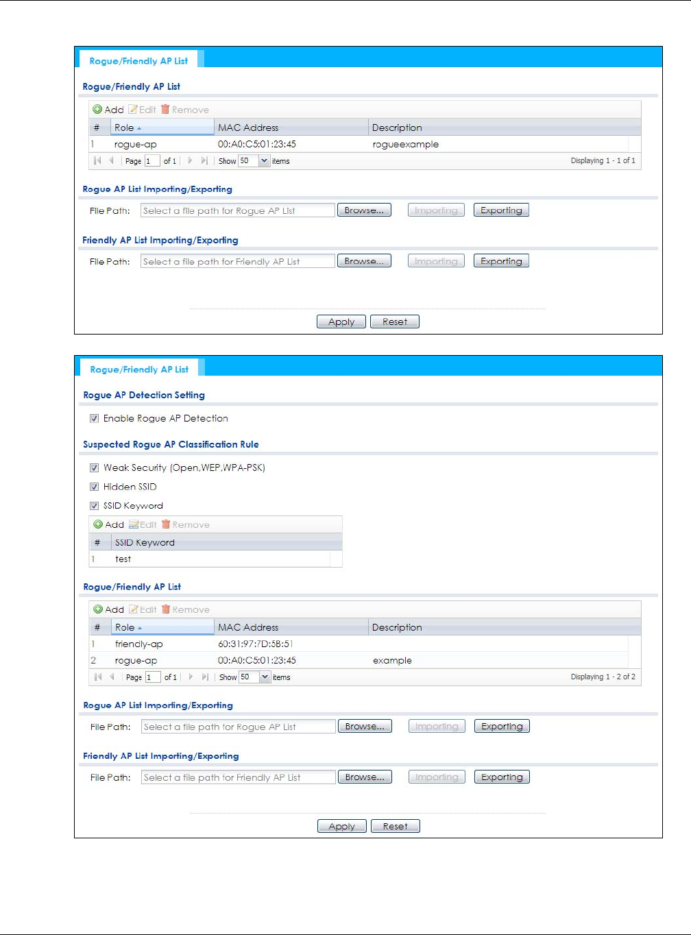
Figure 51 Configuration > Wireless > Rogue AP (for NWA/WAC that supports Monitor mode)
Figure 52 Configuration > Wireless > Rogue AP (for NWA/WAC that doesn’t support Monitor mode)

Chapter 7 Wireless
NWA / WAC Series User’s Guide
90
Each field is described in the following table.
7.3.1 Add/Edit Rogue/Friendly List
Click Add or select an AP and click the Edit button in the Configuration > Wireless > Rogue AP table to
display this screen.
Table 38 Configuration > Wireless > Rogue AP
LABEL DESCRIPTION
Rogue AP Detection
Setting
Enable Rogue AP
Detection
Select this option to detect Rogue APs in the network.
Suspected Rogue AP
Classification Rule
Click the check boxes (Weak Security (Open, WEP, WPA-PSK), Hidden SSID, SSID
Keyword) of the characteristics an AP should have for the NWA/WAC to rule it as a
Rogue AP.
Add Click this to add an SSID Keyword.
Edit Select an SSID Keyword and click this button to modify it.
Remove Select an existing SSID keyword and click this button to delete it.
#This is the SSID Keyword’s index number in this list.
SSID Keyword This field displays the SSID Keyword.
Rogue/Friendly AP List
Add Click this button to add an AP to the list and assign it either friendly or rogue status.
Edit Select an AP in the list to edit and reassign its status.
Remove Select an AP in the list to remove.
# This field is a sequential value, and it is not associated with any interface.
Role This field indicates whether the selected AP is a rogue-ap or a friendly-ap. To change
the AP’s role, click the Edit button.
MAC Address This field indicates the AP’s radio MAC address.
Description This field displays the AP’s description. You can modify this by clicking the Edit button.
Rogue/Friendly AP List
Importing/Exporting
These controls allow you to export the current list of rogue and friendly APs or import
existing lists.
File Path / Browse /
Importing Enter the file name and path of the list you want to import or click the Browse button
to locate it. Once the File Path field has been populated, click Importing to bring the
list into the NWA/WAC.
You need to wait a while for the importing process to finish.
Exporting Click this button to export the current list of either rogue APs or friendly APS.
Apply Click Apply to save your changes back to the NWA/WAC.
Reset Click Reset to return the screen to its last-saved settings.
Chapter 7 Wireless
NWA / WAC Series User’s Guide
91
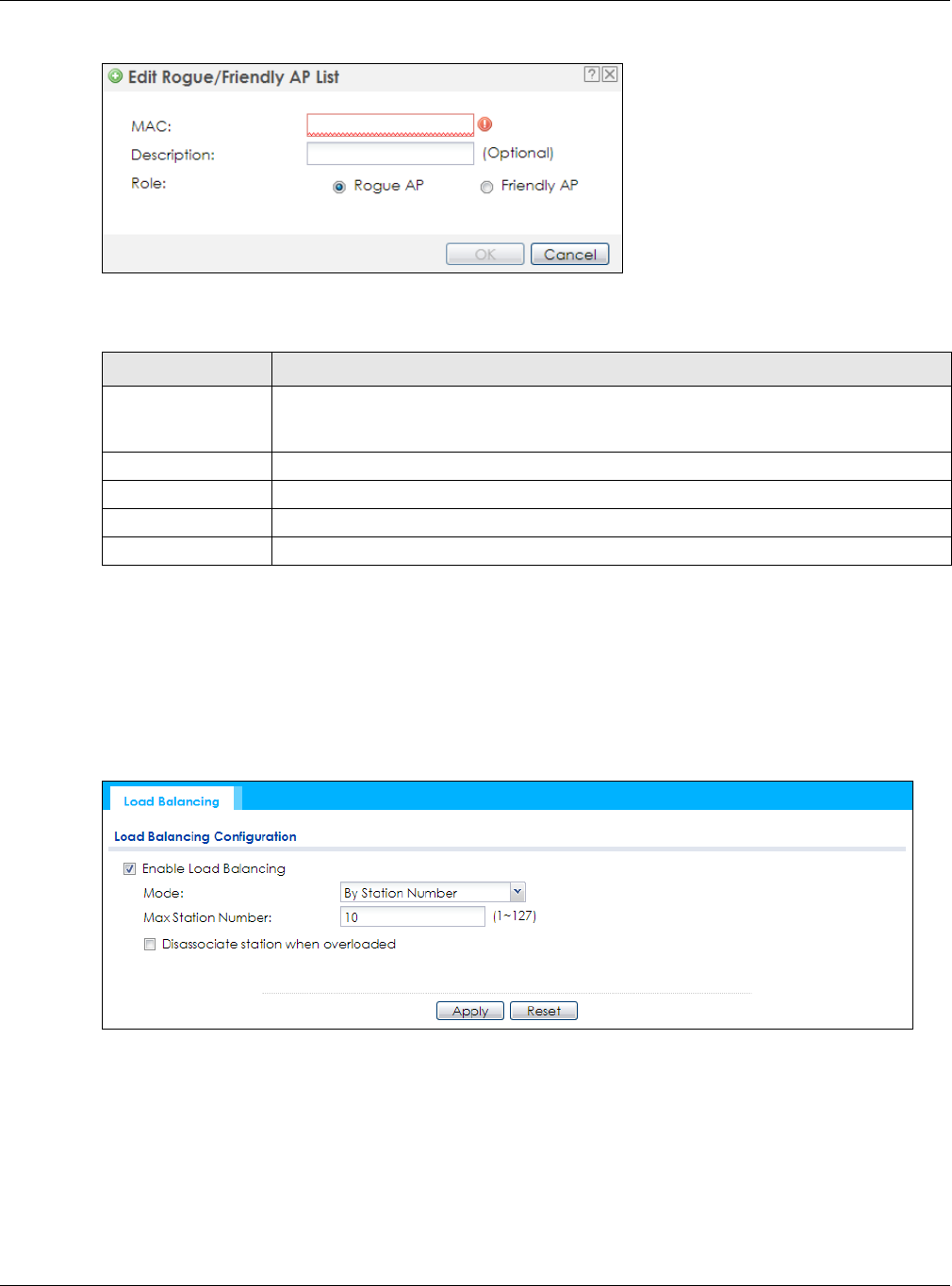
Figure 53 Configuration > Wireless > Rogue AP > Add/Edit Rogue/Friendly AP List
Each field is described in the following table.
7.4 Load Balancing
Use this screen to configure wireless network traffic load balancing between the APs on your network.
Click Configuration > Wireless > Load Balancing to access this screen.
Figure 54 Configuration > Wireless > Load Balancing
Table 39 Configuration > Wireless > Rogue AP > Add/Edit Rogue/Friendly AP List
LABEL DESCRIPTION
MAC Enter the MAC address of the AP you want to add to the list. A MAC address is a unique
hardware identifier in the following hexadecimal format: xx:xx:xx:xx:xx:xx where xx is a
hexadecimal number separated by colons.
Description Enter up to 60 characters for the AP’s description. Spaces and underscores are allowed.
Role Select either Rogue AP or Friendly AP for the AP’s role.
OK Click OK to save your changes back to the NWA/WAC.
Cancel Click Cancel to close the window with changes unsaved.

Chapter 7 Wireless
NWA / WAC Series User’s Guide
92
Each field is described in the following table.
Table 40 Configuration > Wireless > Load Balancing
LABEL DESCRIPTION
Enable Load
Balancing
Select this to enable load balancing on the NWA/WAC.
Use this section to configure wireless network traffic load balancing between the managed
APs in this group.
Mode Select a mode by which load balancing is carried out.
Select By Station Number to balance network traffic based on the number of specified
stations connected to the NWA/WAC.
Select By Traffic Level to balance network traffic based on the volume generated by the
stations connected to the NWA/WAC.
Select By Smart Classroom to balance network traffic based on the number of specified
stations connected to the NWA/WAC. The NWA/WAC ignores association request and
authentication request packets from any new station when the maximum number of
stations is reached.
If you select By Station Number or By Traffic Level, once the threshold is crossed (either the
maximum station numbers or with network traffic), the NWA/WAC delays association
request and authentication request packets from any new station that attempts to make a
connection. This allows the station to automatically attempt to connect to another, less
burdened AP if one is available.
Max Station
Number Enter the threshold number of stations at which the NWA/WAC begins load balancing its
connections.
Traffic Level Select the threshold traffic level at which the NWA/WAC begins load balancing its
connections (Low, Medium, High).
The maximum bandwidth allowed for each level is:
•Low - 11 Mbps,
•Medium - 23 Mbps
•High - 35M bps
Disassociate
station when
overloaded
This function is enabled by default and the disassociation priority is always Signal Strength
when you set Mode to By Smart Classroom.
Select this option to disassociate wireless clients connected to the AP when it becomes
overloaded. If you do not enable this option, then the AP simply delays the connection until
it can afford the bandwidth it requires, or it transfers the connection to another AP within its
broadcast radius.
The disassociation priority is determined automatically by the NWA/WAC and is as follows:
•Idle Timeout - Devices that have been idle the longest will be kicked first. If none of the
connected devices are idle, then the priority shifts to Signal Strength.
•Signal Strength - Devices with the weakest signal strength will be kicked first.
Note: If you enable this function, you should ensure that there are multiple APs
within the broadcast radius that can accept any rejected or kicked
wireless clients; otherwise, a wireless client attempting to connect to an
overloaded AP will be disassociated permanently and never be allowed to
connect.
Apply Click Apply to save your changes back to the NWA/WAC.
Reset Click Reset to return the screen to its last-saved settings.
Chapter 7 Wireless
NWA / WAC Series User’s Guide
93
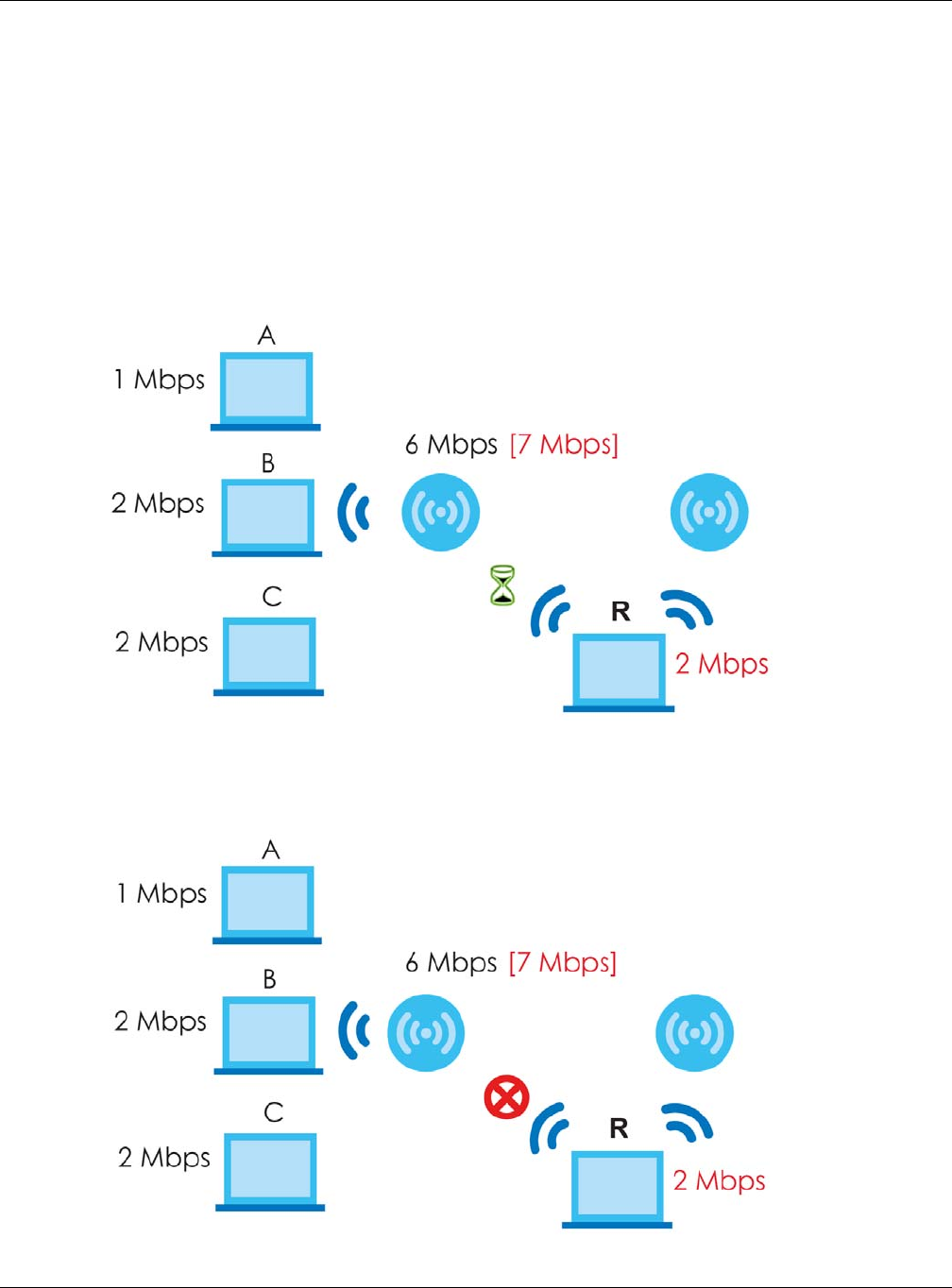
7.4.1 Disassociating and Delaying Connections
When your AP becomes overloaded, there are two basic responses it can take. The first one is to
“delay” a client connection. This means that the AP withholds the connection until the data transfer
throughput is lowered or the client connection is picked up by another AP. If the client is picked up by
another AP then the original AP cannot resume the connection.
For example, here the AP has a balanced bandwidth allotment of 6 Mbps. If laptop R connects and it
pushes the AP over its allotment, say to 7 Mbps, then the AP delays the red laptop’s connection until it
can afford the bandwidth or the laptop is picked up by a different AP with bandwidth to spare.
Figure 55 Delaying a Connection
The second response your AP can take is to kick the connections that are pushing it over its balanced
bandwidth allotment.
Figure 56 Kicking a Connection
Chapter 7 Wireless
NWA / WAC Series User’s Guide
94
Connections are kicked based on either idle timeout or signal strength. The NWA/WAC first looks to see
which devices have been idle the longest, then starts kicking them in order of highest idle time. If no
connections are idle, the next criteria the NWA/WAC analyzes is signal strength. Devices with the
weakest signal strength are kicked first.
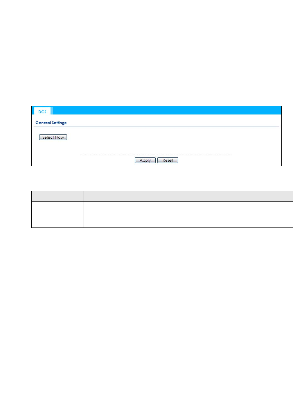
7.5 DCS
Use this screen to configure dynamic radio channel selection. Click Configuration > Wireless > DCS to
access this screen.
Figure 57 Configuration > Wireless > DCS
Each field is described in the following table.
7.6 Technical Reference
The following section contains additional technical information about the features described in this
chapter.
Dynamic Channel Selection
When numerous APs broadcast within a given area, they introduce the possibility of heightened radio
interference, especially if some or all of them are broadcasting on the same radio channel. If the
interference becomes too great, then the network administrator must open his AP configuration options
and manually change the channel to one that no other AP is using (or at least a channel that has a
lower level of interference) in order to give the connected stations a minimum degree of interference.
Dynamic channel selection frees the network administrator from this task by letting the AP do it
automatically. The AP can scan the area around it looking for the channel with the least amount of
interference.
In the 2.4 GHz spectrum, each channel from 1 to 13 is broken up into discrete 22 MHz segments that are
spaced 5 MHz apart. Channel 1 is centered on 2.412 GHz while channel 13 is centered on 2.472 GHz.
Table 41 Configuration > Wireless > DCS
LABEL DESCRIPTION
Select Now Click this to have the NWA/WAC scan for and select an available channel immediately.
Apply Click Apply to save your changes back to the NWA/WAC.
Reset Click Reset to return the screen to its last-saved settings.
Chapter 7 Wireless
NWA / WAC Series User’s Guide
95
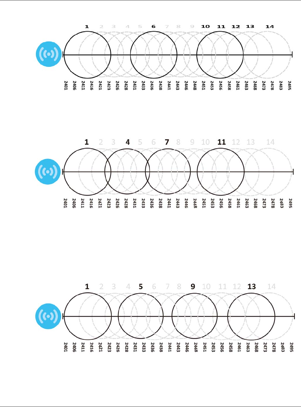
Figure 58 An Example Three-Channel Deployment
Three channels are situated in such a way as to create almost no interference with one another if used
exclusively: 1, 6 and 11. When an AP broadcasts on any of these three channels, it should not interfere
with neighboring APs as long as they are also limited to same trio.
Figure 59 An Example Four-Channel Deployment
However, some regions require the use of other channels and often use a safety scheme with the
following four channels: 1, 4, 7 and 11. While they are situated sufficiently close to both each other and
the three so-called “safe” channels (1,6 and 11) that interference becomes inevitable, the severity of it is
dependent upon other factors: proximity to the affected AP, signal strength, activity, and so on.
Finally, there is an alternative four channel scheme for ETSI, consisting of channels 1, 5, 9, 13. This offers
significantly less overlap that the other one.
Figure 60 An Alternative Four-Channel Deployment
Load Balancing
Because there is a hard upper limit on an AP’s wireless bandwidth, load balancing can be crucial in
areas crowded with wireless users. Rather than let every user connect and subsequently dilute the

Chapter 7 Wireless
NWA / WAC Series User’s Guide
96
available bandwidth to the point where each connecting device receives a meager trickle, the load
balanced AP instead limits the incoming connections as a means to maintain bandwidth integrity.
There are three kinds of wireless load balancing available on the NWA/WAC:
Load balancing by station number limits the number of devices allowed to connect to your AP. If you
know exactly how many stations you want to let connect, choose this option.
For example, if your company’s graphic design team has their own AP and they have 10 computers,
you can load balance for 10. Later, if someone from the sales department visits the graphic design
team’s offices for a meeting and he tries to access the network, his computer’s connection is delayed,
giving it the opportunity to connect to a different, neighboring AP. If he still connects to the AP
regardless of the delay, then the AP may boot other people who are already connected in order to
associate with the new connection.
Load balancing by smart classroom also limits the number of devices allowed to connect to your AP.
But any new connections will be just rejected when the AP is overloaded.
Load balancing by traffic level limits the number of connections to the AP based on maximum
bandwidth available. If you are uncertain as to the exact number of wireless connections you will have
then choose this option. By setting a maximum bandwidth cap, you allow any number of devices to
connect as long as their total bandwidth usage does not exceed the configured bandwidth cap
associated with this setting. Once the cap is hit, any new connections are rejected or delayed provided
that there are other APs in range.
Imagine a coffee shop in a crowded business district that offers free wireless connectivity to its
customers. The coffee shop owner can’t possibly know how many connections his AP will have at any
given moment. As such, he decides to put a limit on the bandwidth that is available to his customers but
not on the actual number of connections he allows. This means anyone can connect to his wireless
network as long as the AP has the bandwidth to spare. If too many people connect and the AP hits its
bandwidth cap then all new connections must basically wait for their turn or get shunted to the nearest
identical AP.

NWA / WAC Series User’s Guide
97
CHAPTER 8
Bluetooth
8.1 Overview
Use this screen to configure the Bluetooth advertising settings for the NWA/WAC that supports Bluetooth
Low Energy (BLE). Bluetooth Low Energy, which is also known as Bluetooth Smart, transmits less data over
a shorter distance and consumes less power than classic Bluetooth.
8.1.1 What You Need To Know
iBeacon is Apple’s communication protocol on top of Bluetooth Low Energy wireless technology.
Beacons (Bluetooth radio transmitters) or BLE enabled devices broadcast packets to every device
around it to announce their presence. Advertising packets contain their iBeacon ID which mainly
consists of the UUID, major number, minor number and TX (transmit) power. The ID is used to distinguish
beacons in your network.
The universally unique identifier (UUID) is a 128-bit (16-byte) number which can be used to identify a
service, a device, a manufacturer or an owner. The 2-byte major number is to identify and distinguish a
group, and the 2-byte minor number is to identify and distinguish an individual.
For example, you can set all the beacons in one network to share the same UUID, the beacons in a
particular room to use the same major number, and each beacon in the room can have its own minor
number.
8.2 Bluetooth Advertising Settings
The NWA/WAC communicates with another BLE enabled device using advertisements. Use this screen
to configure the beacon ID(s) to be included in the advertising packet. You can have up to five
combinations of the UUID, Major and Minor parameters.
To access this screen, click Configuration > Bluetooth > Advertising Settings.
NETWORK A
ROOM X ROOM Y
BEACON 1 BEACON 2 BEACON 3
UUID EBAECFAF-DFE0-4039-BE5A-F030EED4303C
Major 10 10 20
Minor 121
Chapter 8 Bluetooth
NWA / WAC Series User’s Guide
98
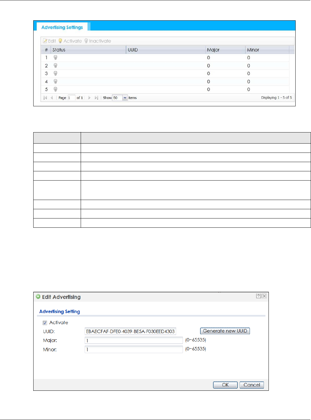
Figure 61 Configuration > Bluetooth > Advertising Settings
The following table describes the labels in this screen.
8.2.1 Edit Advertising Settings
Select an entry in the Configuration > Bluetooth > Advertising Settings screen and click the Edit icon to
open the Edit Advertising screen. Use this screen to configure the beacon ID in the Bluetooth advertising
packets.
Figure 62 Configuration > Bluetooth > Advertising Settings > Edit
Table 42 Configuration > Bluetooth > Advertising Settings
LABEL DESCRIPTION
Edit Click this to edit the selected entry.
Activate To turn on an entry, select it and click Activate.
Inactivate To turn off an entry, select it and click Inactivate.
# This field is a sequential value, and it is not associated with a specific entry.
Status This field shows whether or not the entry is activated.
A yellow bulb signifies that this rule is active. A gray bulb signifies that this rule is not active.
UUID This field indicates the UUID to be included in the Bluetooth advertising packets.
Major This field indicates the major number to be included in the Bluetooth advertising packets.
Minor This field indicates the minor number to be included in the Bluetooth advertising packets.

Chapter 8 Bluetooth
NWA / WAC Series User’s Guide
99
The following table describes the labels in this screen.
Table 43 Configuration > Bluetooth > Advertising Settings > Edit
LABEL DESCRIPTION
Activate Select this option to enable the advertising settings.
UUID To specify a UUID of the NWA/WAC’s beacon ID, enter 32 hexadecimal digits in the range of
“A-F”, “a-f” and “0-9”, split into five groups separated by hyphens (-). The UUID format is as
follows: xxxxxxxx-xxxx-xxxx-xxxx-xxxxxxxxxxxx (8-4-4-4-12)
Generate new
UUID
Click this button to have the NWA/WAC generate a UUID automatically.
Major Enter an integer from 0 to 65535 as the major value to identify the beacon.
Minor Enter an integer from 0 to 65535 as the minor value to identify the beacon.
OK Click OK to save your changes back to the NWA/WAC.
Cancel Click Cancel to exit this screen without saving your changes.
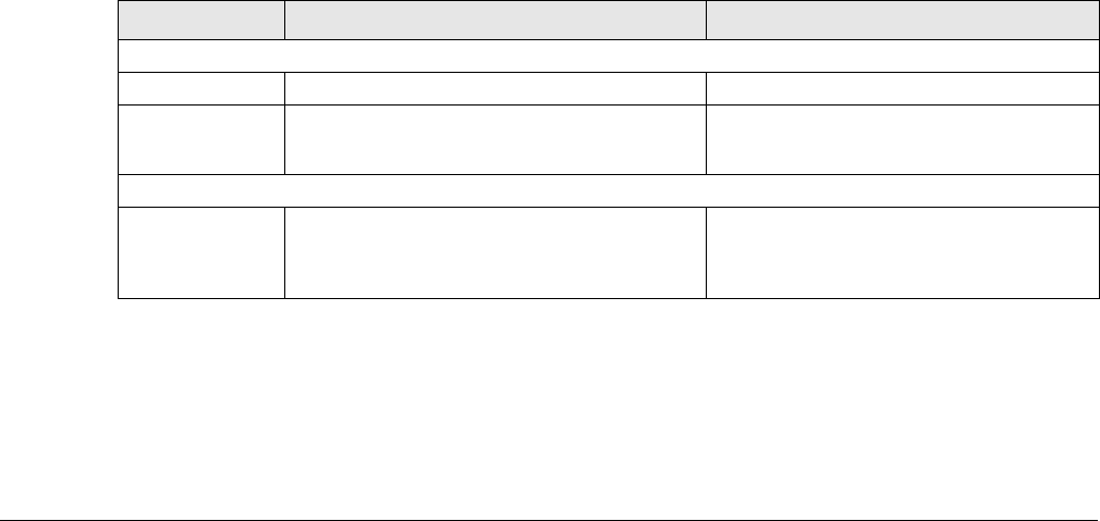
NWA / WAC Series User’s Guide
100
CHAPTER 9
User
9.1 Overview
This chapter describes how to set up user accounts and user settings for the NWA/WAC.
9.1.1 What You Can Do in this Chapter
• The User screen (see Section 9.2 on page 101) provides a summary of all user accounts.
•The Setting screen (see Section 9.3 on page 103) controls default settings, login settings, lockout
settings, and other user settings for the NWA/WAC.
9.1.2 What You Need To Know
The following terms and concepts may help as you read this chapter.
User Account
A user account defines the privileges of a user logged into the NWA/WAC. User accounts are used in
controlling access to configuration and services in the NWA/WAC.
User Types
These are the types of user accounts the NWA/WAC uses.
Note: The default admin account is always authenticated locally, regardless of the
authentication method setting.
Table 44 Types of User Accounts
TYPE ABILITIES LOGIN METHOD(S)
Admin Users
admin Change NWA/WAC configuration (web, CLI) WWW, TELNET, SSH, FTP
limited-admin Look at NWA/WAC configuration (web, CLI)
Perform basic diagnostics (CLI)
WWW, TELNET, SSH
Access Users
user Used for the embedded RADIUS server and
SNMPv3 user access
Browse user-mode commands (CLI)
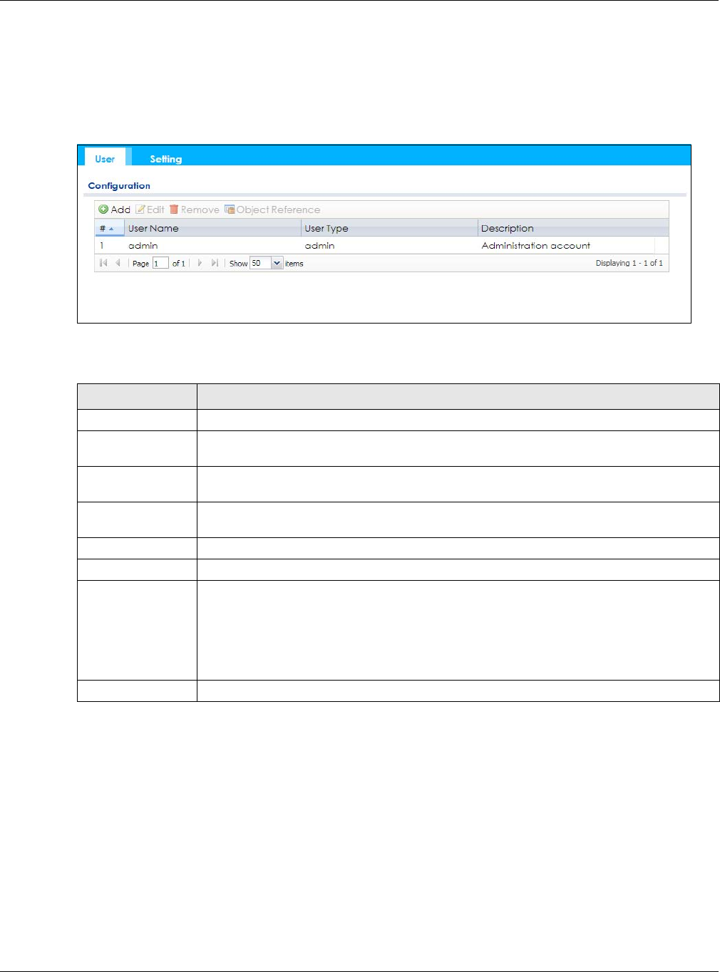
Chapter 9 User
NWA / WAC Series User’s Guide
101
9.2 User Summary
The User screen provides a summary of all user accounts. To access this screen click Configuration >
Object > User.
Figure 63 Configuration > Object > User
The following table describes the labels in this screen.
9.2.1 Add/Edit User
The User Add/Edit screen allows you to create a new user account or edit an existing one.
9.2.1.1 Rules for User Names
Enter a user name from 1 to 31 characters.
The user name can only contain the following characters:
• Alphanumeric A-z 0-9 (there is no unicode support)
• _ [underscores]
Table 45 Configuration > Object > User
LABEL DESCRIPTION
Add Click this to create a new entry.
Edit Double-click an entry or select it and click Edit to open a screen where you can modify the
entry’s settings.
Remove To remove an entry, select it and click Remove. The NWA/WAC confirms you want to remove
it before doing so.
Object Reference Select an entry and click Object Reference to open a screen that shows which settings use
the entry.
# This field is a sequential value, and it is not associated with a specific user.
User Name This field displays the user name of each user.
User Type This field displays type of user this account was configured as.
•admin - this user can look at and change the configuration of the NWA/WAC
•limited-admin - this user can look at the configuration of the NWA/WAC but not to
change it
•user - this user has access to the NWA/WAC’s services but cannot look at the
configuration
Description This field displays the description for each user.
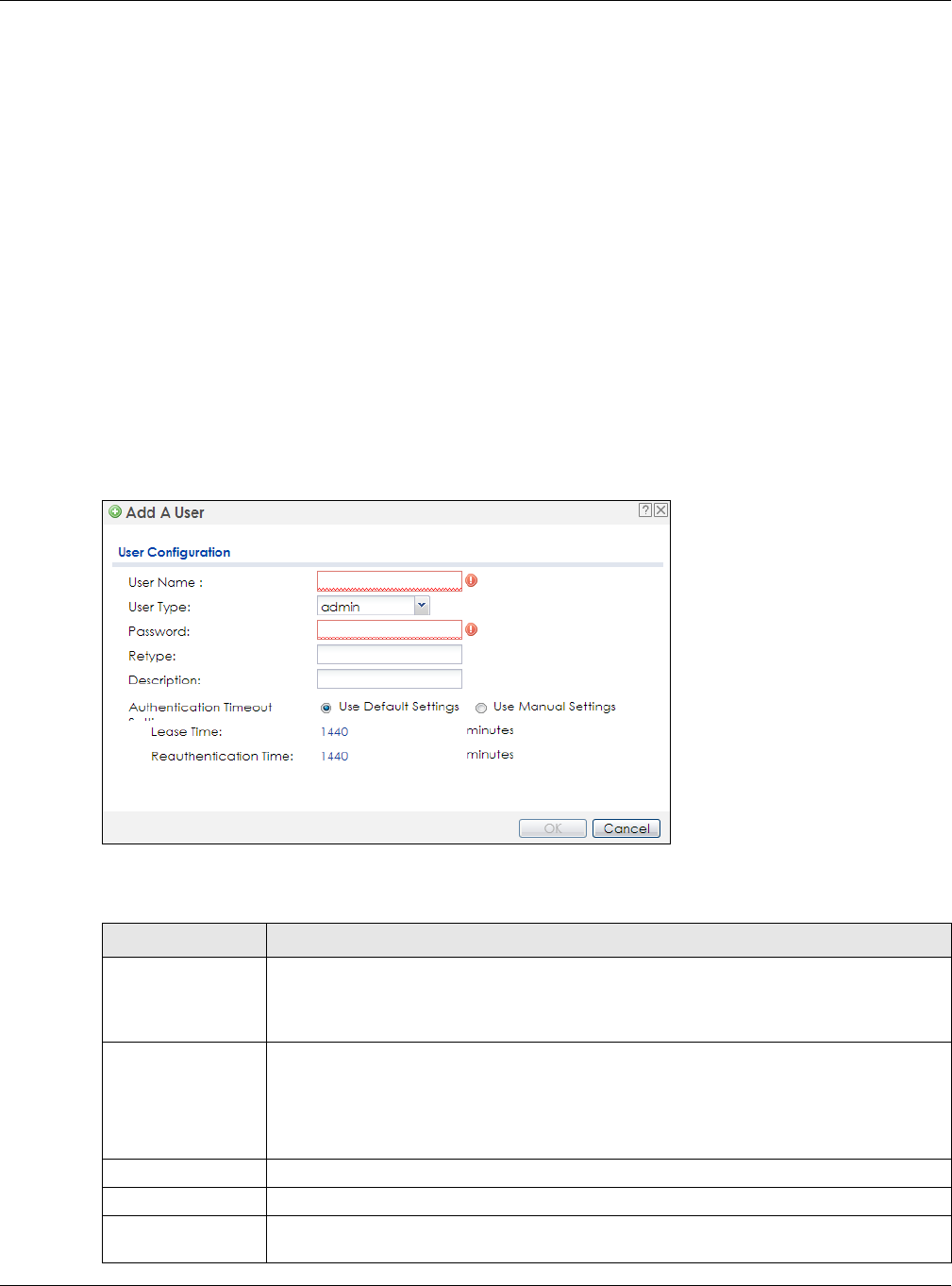
Chapter 9 User
NWA / WAC Series User’s Guide
102
• - [dashes]
The first character must be alphabetical (A-Z a-z), an underscore (_), or a dash (-). Other limitations on
user names are:
• User names are case-sensitive. If you enter a user 'bob' but use 'BOB' when connecting via CIFS or FTP,
it will use the account settings used for 'BOB' not ‘bob’.
• User names have to be different than user group names.
• Here are the reserved user names:
To access this screen, go to the User screen, and click Add or Edit.
Figure 64 Configuration > Object > User > Add/Edit A User
The following table describes the labels in this screen.
•adm •admin •any •bin •daemon
•debug •devicehaecived•ftp •games •halt
•ldap-users •lp •mail •news •nobody
• operator • radius-users • root • shutdown • sshd
• sync • uucp • zyxel
Table 46 Configuration > User > User > Add/Edit A User
LABEL DESCRIPTION
User Name Type the user name for this user account. You may use 1-31 alphanumeric characters,
underscores(_), or dashes (-), but the first character cannot be a number. This value is case-
sensitive. User names have to be different than user group names, and some words are
reserved.
User Type Select what type of user this is. Choices are:
•admin - this user can look at and change the configuration of the NWA/WAC
•limited-admin - this user can look at the configuration of the NWA/WAC but not to
change it
•user - this is used for embedded RADIUS server and SNMPv3 user access
Password Enter the password of this user account. It can consist of 4 - 63 alphanumeric characters.
Retype Re-enter the password to make sure you have entered it correctly.
Description Enter the description of each user, if any. You can use up to 60 printable ASCII characters.
Default descriptions are provided.

Chapter 9 User
NWA / WAC Series User’s Guide
103
9.3 Setting
This screen controls default settings, login settings, lockout settings, and other user settings for the NWA/
WAC.
To access this screen, login to the Web Configurator, and click Configuration > Object > User > Setting.
Authentication
Timeout Settings
This field is not available if the user type is user.
If you want to set authentication timeout to a value other than the default settings, select
Use Manual Settings then fill your preferred values in the fields that follow.
Lease Time This field is not available if the user type is user.
Enter the number of minutes this user has to renew the current session before the user is
logged out. You can specify 1 to 1440 minutes. You can enter 0 to make the number of
minutes unlimited. Admin users renew the session every time the main screen refreshes in the
Web Configurator.
Reauthentication
Time
This field is not available if the user type is user.
Type the number of minutes this user can be logged into the NWA/WAC in one session
before the user has to log in again. You can specify 1 to 1440 minutes. You can enter 0 to
make the number of minutes unlimited. Unlike Lease Time, the user has no opportunity to
renew the session without logging out.
OK Click OK to save your changes back to the NWA/WAC.
Cancel Click Cancel to exit this screen without saving your changes.
Table 46 Configuration > User > User > Add/Edit A User (continued)
LABEL DESCRIPTION
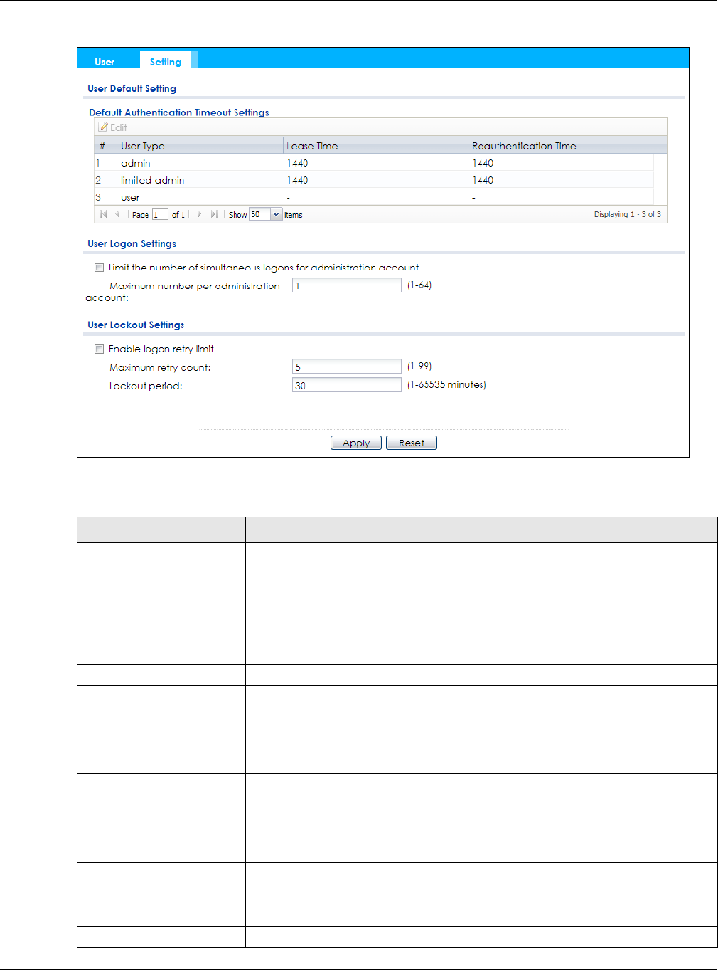
Chapter 9 User
NWA / WAC Series User’s Guide
104
Figure 65 Configuration > Object > User > Setting
The following table describes the labels in this screen.
Table 47 Configuration > Object > User > Setting
LABEL DESCRIPTION
User Default Setting
Default Authentication
Timeout Settings
These authentication timeout settings are used by default when you create a new
user account. They also control the settings for any existing user accounts that are
set to use the default settings. You can still manually configure any user account’s
authentication timeout settings.
Edit Double-click an entry or select it and click Edit to open a screen where you can
modify the entry’s settings.
# This field is a sequential value, and it is not associated with a specific entry.
User Type These are the kinds of user account the NWA/WAC supports.
•admin - this user can look at and change the configuration of the NWA/WAC
•limited-admin - this user can look at the configuration of the NWA/WAC but not
to change it
•user - this is used for embedded RADIUS server and SNMPv3 user access
Lease Time This is the default lease time in minutes for each type of user account. It defines the
number of minutes the user has to renew the current session before the user is
logged out.
Admin users renew the session every time the main screen refreshes in the Web
Configurator.
Reauthentication Time This is the default reauthentication time in minutes for each type of user account. It
defines the number of minutes the user can be logged into the NWA/WAC in one
session before having to log in again. Unlike Lease Time, the user has no opportunity
to renew the session without logging out.
User Logon Settings
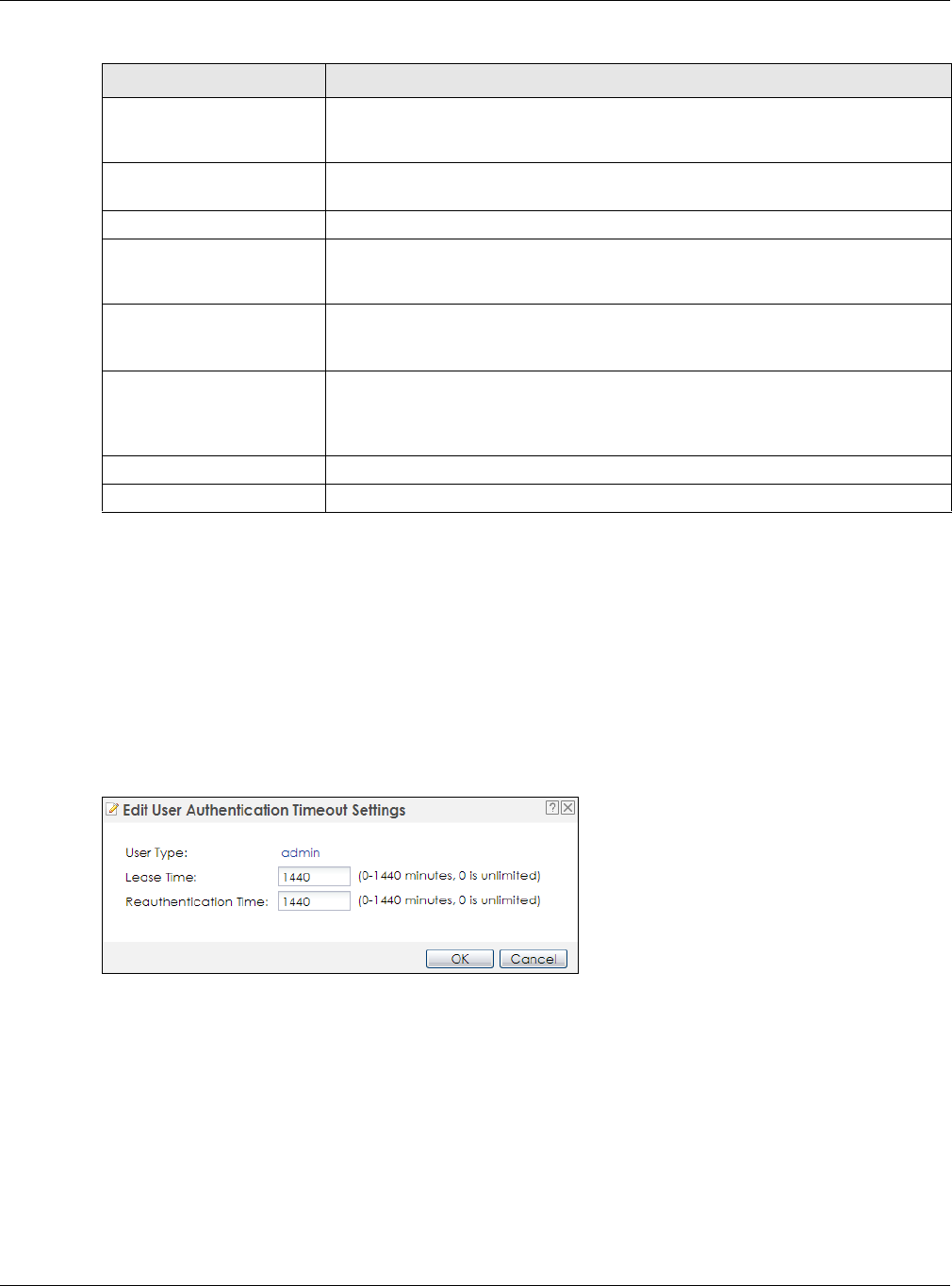
Chapter 9 User
NWA / WAC Series User’s Guide
105
9.3.1 Edit User Authentication Timeout Settings
This screen allows you to set the default authentication timeout settings for the selected type of user
account. These default authentication timeout settings also control the settings for any existing user
accounts that are set to use the default settings. You can still manually configure any user account’s
authentication timeout settings.
To access this screen, go to the Configuration > Object > User > Setting screen, select one of the Default
Authentication Timeout Settings entry and click the Edit icon.
Figure 66 User > Setting > Edit User Authentication Timeout Settings
Limit the number of
simultaneous logons for
administration account
Select this check box if you want to set a limit on the number of simultaneous logins
by admin users. If you do not select this, admin users can login as many times as they
want at the same time using the same or different IP addresses.
Maximum number per
administration account This field is effective when Limit ... for administration account is checked. Type the
maximum number of simultaneous logins by each admin user.
User Lockout Settings
Enable logon retry limit Select this check box to set a limit on the number of times each user can login
unsuccessfully (for example, wrong password) before the IP address is locked out for
a specified amount of time.
Maximum retry count This field is effective when Enable logon retry limit is checked. Type the maximum
number of times each user can login unsuccessfully before the IP address is locked
out for the specified lockout period. The number must be between 1 and 99.
Lockout period This field is effective when Enable logon retry limit is checked. Type the number of
minutes the user must wait to try to login again, if logon retry limit is enabled and the
maximum retry count is reached. This number must be between 1 and 65,535 (about
45.5 days).
Apply Click Apply to save the changes.
Reset Click Reset to return the screen to its last-saved settings.
Table 47 Configuration > Object > User > Setting (continued)
LABEL DESCRIPTION

Chapter 9 User
NWA / WAC Series User’s Guide
106
The following table describes the labels in this screen.
Table 48 User > Setting > Edit User Authentication Timeout Settings
LABEL DESCRIPTION
User Type This read-only field identifies the type of user account for which you are configuring the
default settings.
•admin - this user can look at and change the configuration of the NWA/WAC.
•limited-admin - this user can look at the configuration of the NWA/WAC but not to
change it.
Lease Time Enter the number of minutes this type of user account has to renew the current session
before the user is logged out. You can specify 1 to 1440 minutes. You can enter 0 to make
the number of minutes unlimited.
Admin users renew the session every time the main screen refreshes in the Web Configurator.
Access users can renew the session by clicking the Renew button on their screen. If you allow
access users to renew time automatically, the users can select this check box on their screen
as well. In this case, the session is automatically renewed before the lease time expires.
Reauthentication
Time
Type the number of minutes this type of user account can be logged into the NWA/WAC in
one session before the user has to log in again. You can specify 1 to 1440 minutes. You can
enter 0 to make the number of minutes unlimited. Unlike Lease Time, the user has no
opportunity to renew the session without logging out.
OK Click OK to save your changes back to the NWA/WAC.
Cancel Click Cancel to exit this screen without saving your changes.

NWA / WAC Series User’s Guide
107
CHAPTER 10
AP Profile
10.1 Overview
This chapter shows you how to configure preset profiles for the NWA/WAC.
10.1.1 What You Can Do in this Chapter
• The Radio screen (Section 10.2 on page 108) creates radio configurations that can be used by the
APs.
• The SSID screen (Section 10.3 on page 114) configures three different types of profiles for your
networked APs.
10.1.2 What You Need To Know
The following terms and concepts may help as you read this chapter.
Wireless Profiles
At the heart of all wireless AP configurations on the NWA/WAC are profiles. A profile represents a group
of saved settings that you can use across any number of connected APs. You can set up the following
wireless profile types:
•Radio - This profile type defines the properties of an AP’s radio transmitter. You can have a maximum
of 32 radio profiles on the NWA/WAC.
•SSID - This profile type defines the properties of a single wireless network signal broadcast by an AP.
Each radio on a single AP can broadcast up to 8 SSIDs. You can have a maximum of 32 SSID profiles
on the NWA/WAC.
•Security - This profile type defines the security settings used by a single SSID. It controls the encryption
method required for a wireless client to associate itself with the SSID. You can have a maximum of 32
security profiles on the NWA/WAC.
•MAC Filtering - This profile provides an additional layer of security for an SSID, allowing you to block
access or allow access to that SSID based on wireless client MAC addresses. If a client’s MAC address
is on the list, then it is either allowed or denied, depending on how you set up the MAC Filter profile.
You can have a maximum of 32 MAC filtering profiles on the NWA/WAC.
•Layer-2 Isolation - This profile defines the MAC addresses of the devices that you want to allow the
associated wireless clients to have access to when layer-2 isolation is enabled.
SSID
The SSID (Service Set IDentifier) is the name that identifies the Service Set with which a wireless station is
associated. Wireless stations associating to the access point (AP) must have the same SSID. In other
words, it is the name of the wireless network that clients use to connect to it.
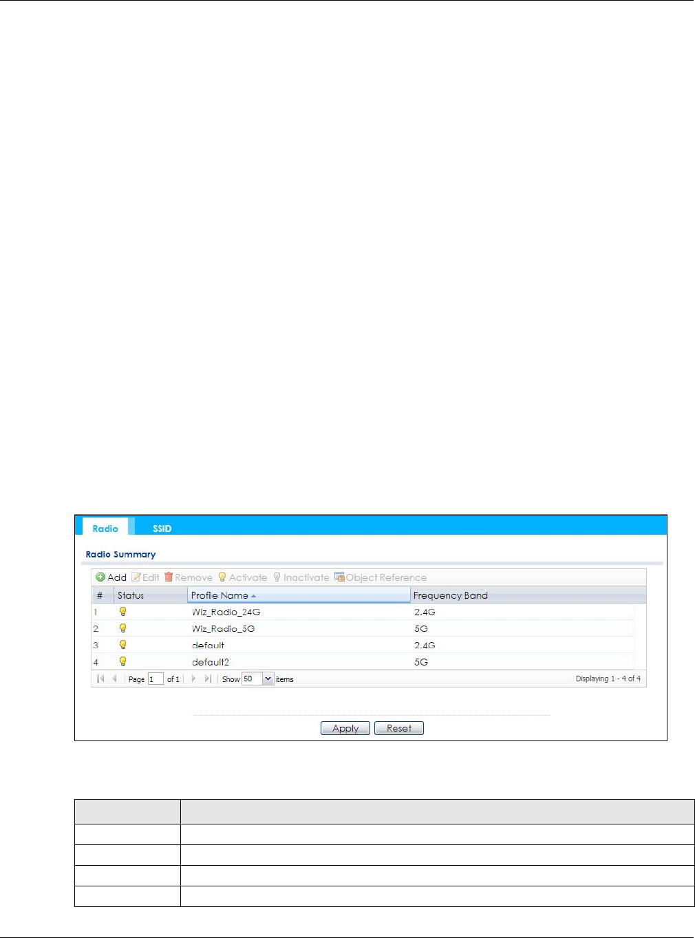
Chapter 10 AP Profile
NWA / WAC Series User’s Guide
108
WEP
WEP (Wired Equivalent Privacy) encryption scrambles all data packets transmitted between the AP and
the wireless stations associated with it in order to keep network communications private. Both the
wireless stations and the access points must use the same WEP key for data encryption and decryption.
WPA2
WPA2 (IEEE 802.11i) is a wireless security standard that defines stronger encryption, authentication and
key management than WPA. Key differences between WPA2 and WEP are improved data encryption
and user authentication.
IEEE 802.1x
The IEEE 802.1x standard outlines enhanced security methods for both the authentication of wireless
stations and encryption key management. Authentication is done using an external RADIUS server.
10.2 Radio
This screen allows you to create radio profiles for the NWA/WAC. A radio profile is a list of settings that an
NWA/WAC can use to configure its radio transmitter(s). To access this screen click Configuration >
Object > AP Profile.
Note: You can have a maximum of 32 radio profiles on the NWA/WAC.
Figure 67 Configuration > Object > AP Profile > Radio
The following table describes the labels in this screen.
Table 49 Configuration > Object > AP Profile > Radio
LABEL DESCRIPTION
Add Click this to add a new radio profile.
Edit Click this to edit the selected radio profile.
Remove Click this to remove the selected radio profile.
Activate To turn on an entry, select it and click Activate.

Chapter 10 AP Profile
NWA / WAC Series User’s Guide
109
10.2.1 Add/Edit Radio Profile
This screen allows you to create a new radio profile or edit an existing one. To access this screen, click
the Add button or select a radio profile from the list and click the Edit button.
Inactivate To turn off an entry, select it and click Inactivate.
Object
Reference
Click this to view which other objects are linked to the selected radio profile.
# This field is a sequential value, and it is not associated with a specific user.
Status This field shows whether or not the entry is activated.
A yellow bulb signifies that this rule is active. A gray bulb signifies that this rule is not active.
Profile Name This field indicates the name assigned to the radio profile.
Frequency Band This field indicates the frequency band which this radio profile is configured to use.
Apply Click Apply to save your changes back to the NWA/WAC.
Reset Click Reset to return the screen to its last-saved settings.
Table 49 Configuration > Object > AP Profile > Radio (continued)
LABEL DESCRIPTION
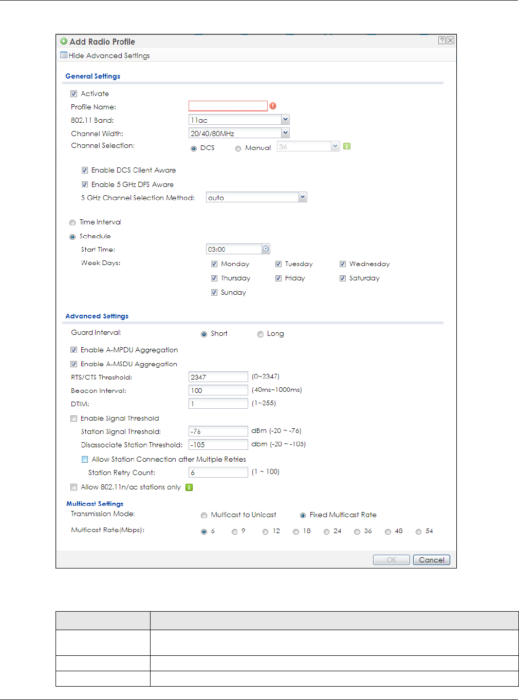
Chapter 10 AP Profile
NWA / WAC Series User’s Guide
110
Figure 68 Configuration > Object > AP Profile > Add/Edit Profile
The following table describes the labels in this screen.
Table 50 Configuration > Object > AP Profile > Add/Edit Profile
LABEL DESCRIPTION
Hide / Show
Advanced Settings
Click this to hide or show the Advanced Settings in this window.
General Settings
Activate Select this option to make this profile active.

Chapter 10 AP Profile
NWA / WAC Series User’s Guide
111
Profile Name Enter up to 31 alphanumeric characters to be used as this profile’s name. Spaces and
underscores are allowed.
802.11 Band Select the wireless band which this radio profile should use. Not all NWA/WACs support
both 2.4 GHz and 5 GHz frequency bands.
2.4 GHz is the frequency used by IEEE 802.11b/g/n wireless clients.
5 GHz is the frequency used by IEEE 802.11ac/a/n wireless clients.
•11b/g: allows either IEEE 802.11b or IEEE 802.11g compliant WLAN devices to associate
with the NWA/WAC. The NWA/WAC adjusts the transmission rate automatically
according to the wireless standard supported by the wireless devices.
•11b/g/n: allows IEEE802.11b, IEEE802.11g and IEEE802.11n compliant WLAN devices to
associate with the NWA/WAC. The transmission rate of your NWA/WAC might be
reduced.
•11a: allows only IEEE 802.11a compliant WLAN devices to associate with the NWA/WAC.
•11a/n: allows both IEEE802.11n and IEEE802.11a compliant WLAN devices to associate
with the NWA/WAC. The transmission rate of your NWA/WAC might be reduced.
•11ac: allows IEEE 802.11ac compliant WLAN devices to associate with the WAC.
Channel Width Select the channel bandwidth you want to use for your wireless network.
Select 20 MHz if you want to lessen radio interference with other wireless devices in your
neighborhood.
Select 20/40 MHz to allow the NWA/WAC to choose the channel bandwidth (20 or 40 MHz)
that has least interference.
Select 20/40/80 MHz to allow the NWA/WAC to choose the channel bandwidth (20 or 40 or
80 MHz) that has least interference. This option is available only when you select 11ac in the
802.11 Band field.
Channel
Selection This is the radio channel which the signal will use for broadcasting by this radio profile.
•DCS: Choose Dynamic Channel Selection to have the NWA/WAC choose a radio
channel that has least interference.
•Manual: Choose from the available radio channels in the list. If your NWA/WAC is
outdoor type, be sure to choose non-indoors channels.
Enable DCS
Client Aware Select this to have the NWA/WAC switch channels only when there are no clients
connected to it. If there is a client connected, the NWA/WAC will not switch channels but
generate a log. The NWA/WAC tries to scan and switch channels again at the end of the
specified time interval or at the scheduled time.
If you disable this then the NWA/WAC switches channels immediately regardless of any
client connections. In this instance, clients that are connected to the NWA/WAC when it
switches channels are dropped.
2.4 GHz Channel
Selection Method Select how you want to specify the channels the NWA/WAC switches between for 2.4 GHz
operation. This field appears only when you choose 802.11b/g/n mode.
Select auto to have the NWA/WAC display a 2.4 GHz Channel Deployment field you can
use to limit channel switching to 3 or 4 channels.
Select manual to select the individual channels the NWA/WAC switches between.
Note: The method is automatically set to auto when no channel is selected or
any one of the previously selected channels is not supported.
Channel ID This field is available only when you set Channel Selection to DCS and set 2.4 GHz Channel
Selection Method to manual.
Select the channels that you want the NWA/WAC to use.
Table 50 Configuration > Object > AP Profile > Add/Edit Profile (continued)
LABEL DESCRIPTION

Chapter 10 AP Profile
NWA / WAC Series User’s Guide
112
2.4 GHz Channel
Deployment This is available when the 2.4 GHz Channel Selection Method is set to auto.
Select Three-Channel Deployment to limit channel switching to channels 1,6, and 11, the
three channels that are sufficiently attenuated to have almost no impact on one another.
In other words, this allows you to minimize channel interference by limiting channel-
hopping to these three “safe” channels.
Select Four-Channel Deployment to limit channel switching to four channels. Depending
on the country domain, if the only allowable channels are 1-11 then the NWA/WAC uses
channels 1, 4, 7, 11 in this configuration; otherwise, the NWA/WAC uses channels 1, 5, 9, 13
in this configuration. Four channel deployment expands your pool of possible channels
while keeping the channel interference to a minimum.
Enable 5 GHz DFS
Aware This field is available only when you select 11a, 11a/n or 11ac in the 802.11 Band field and
set 5 GHz Channel Selection Method to auto.
Select this if your APs are operating in an area known to have RADAR devices. This allows
the device to downgrade its frequency to below 5 GHz in the event RADAR signal is
detected, thus preventing it from interfering with that signal.
Enabling this forces the AP to select a non-DFS channel.
5 GHz Channel
Selection Method Select how you want to specify the channels the NWA/WAC switches between for 5 GHz
operation.
Select Auto to have the NWA/WAC automatically select the best channel.
Select manual to select the individual channels the NWA/WAC switches between.
Note: The method is automatically set to auto when no channel is selected or
any one of the previously selected channels is not supported.
Channel ID This field is available only when you set Channel Selection to DCS and set 5 GHz Channel
Selection Method to manual.
Select the channels that you want the NWA/WAC to use.
Time Interval Select this option to have the NWA/WAC survey the other APs within its broadcast radius at
the end of the specified time interval.
DCS Time Interval This field is available when you set Channel Selection to DCS and select the Time Interval
option.
Enter a number of minutes. This regulates how often the NWA/WAC surveys the other APs
within its broadcast radius. If the channel on which it is currently broadcasting suddenly
comes into use by another AP, the NWA/WAC will then dynamically select the next
available clean channel or a channel with lower interference.
Schedule Select this option to have the NWA/WAC survey the other APs within its broadcast radius at
a specific time on selected days of the week.
Start Time Specify the time of the day (in 24-hour format) to have the NWA/WAC use DCS to
automatically scan and find a less-used channel.
Week Days Select each day of the week to have the NWA/WAC use DCS to automatically scan and
find a less-used channel.
Advanced Settings
Guard Interval Set the guard interval for this radio profile to either short or long. This option isn’t applicable
if you set 802.11 Band to 11a or 11b/g and/or choose 20 MHz channel width.
The guard interval is the gap introduced between data transmission from users in order to
reduce interference. Reducing the interval increases data transfer rates but also increases
interference. Increasing the interval reduces data transfer rates but also reduces
interference.
Table 50 Configuration > Object > AP Profile > Add/Edit Profile (continued)
LABEL DESCRIPTION

Chapter 10 AP Profile
NWA / WAC Series User’s Guide
113
Enable A-MPDU
Aggregation Select this to enable A-MPDU aggregation. This field is not available if you set 802.11 Band
to 11a or 11b/g.
Message Protocol Data Unit (MPDU) aggregation collects Ethernet frames along with their
802.11n headers and wraps them in a 802.11n MAC header. This method is useful for
increasing bandwidth throughput in environments that are prone to high error rates.
Enable A-MSDU
Aggregation Select this to enable A-MSDU aggregation. This field is not available if you set 802.11 Band
to 11a or 11b/g.
Mac Service Data Unit (MSDU) aggregation collects Ethernet frames without any of their
802.11n headers and wraps the header-less payload in a single 802.11n MAC header. This
method is useful for increasing bandwidth throughput. It is also more efficient than A-MPDU
except in environments that are prone to high error rates.
RTS/CTS Threshold Use RTS/CTS to reduce data collisions on the wireless network if you have wireless clients
that are associated with the same AP but out of range of one another. When enabled, a
wireless client sends an RTS (Request To Send) and then waits for a CTS (Clear To Send)
before it transmits. This stops wireless clients from transmitting packets at the same time
(and causing data collisions).
A wireless client sends an RTS for all packets larger than the number (of bytes) that you
enter here. Set the RTS/CTS equal to or higher than the fragmentation threshold to turn RTS/
CTS off.
Beacon Interval When a wirelessly networked device sends a beacon, it includes with it a beacon interval.
This specifies the time period before the device sends the beacon again. The interval tells
receiving devices on the network how long they can wait in low-power mode before
waking up to handle the beacon. A high value helps save current consumption of the
access point.
DTIM Delivery Traffic Indication Message (DTIM) is the time period after which broadcast and
multicast packets are transmitted to mobile clients in the Active Power Management
mode. A high DTIM value can cause clients to lose connectivity with the network. This value
can be set from 1 to 255.
Enable Signal
Threshold Select the check box to use the signal threshold to ensure wireless clients receive good
throughput. This allows only wireless clients with a strong signal to connect to the AP.
Clear the check box to not require wireless clients to have a minimum signal strength to
connect to the AP.
Station Signal
Threshold Set a minimum client signal strength. A wireless client is allowed to connect to the AP only
when its signal strength is stronger than the specified threshold.
-20 dBm is the strongest signal you can require and -76 is the weakest.
Disassociate
Station Threshold Set a minimum kick-off signal strength. When a wireless client’s signal strength is lower than
the specified threshold, the NWA/WAC disconnects the wireless client from the AP.
-20 dBm is the strongest signal you can require and -90 is the weakest.
Allow Station
Connection after
Multiple Retries
Select this option to allow a wireless client to try to associate with the AP again after it is
disconnected due to weak signal strength.
Station Retry
Count Set the maximum number of times a wireless client can attempt to re-connect to the AP
Allow 802.11n/ac
stations only Select this option to allow only 802.11 n/ac clients to connect, and reject 802.11a/b/g
clients.
Multicast Settings
Table 50 Configuration > Object > AP Profile > Add/Edit Profile (continued)
LABEL DESCRIPTION
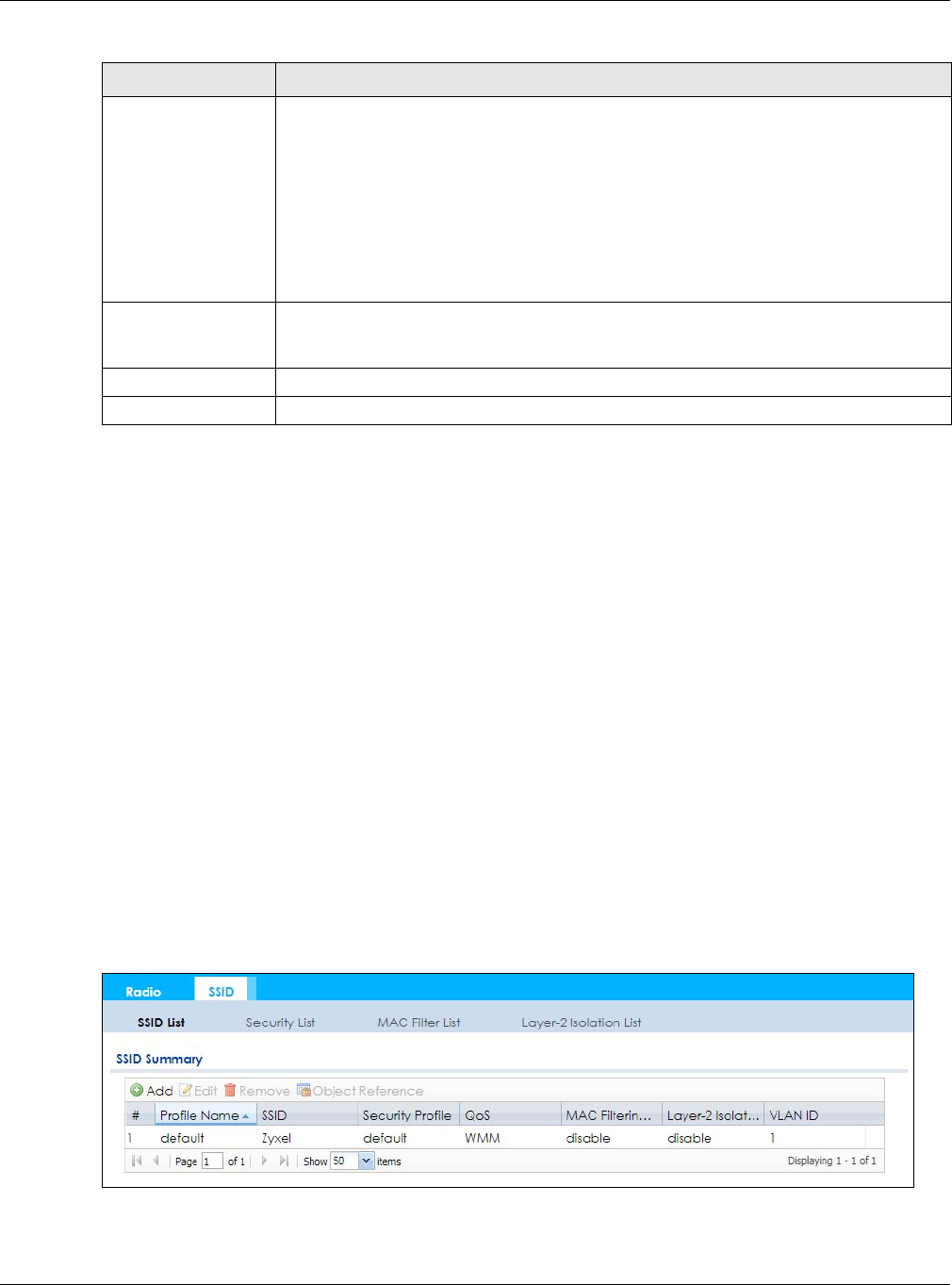
Chapter 10 AP Profile
NWA / WAC Series User’s Guide
114
10.3 SSID
The SSID screens allow you to configure three different types of profiles for your networked APs: an SSID
list, which can assign specific SSID configurations to your APs; a security list, which can assign specific
encryption methods to the APs when allowing wireless clients to connect to them; and a MAC filter list,
which can limit connections to an AP based on wireless clients MAC addresses.
10.3.1 SSID List
This screen allows you to create and manage SSID configurations that can be used by the APs. An SSID,
or Service Set IDentifier, is basically the name of the wireless network to which a wireless client can
connect. The SSID appears as readable text to any device capable of scanning for wireless frequencies
(such as the WiFi adapter in a laptop), and is displayed as the wireless network name when a person
makes a connection to it.
To access this screen click Configuration > Object > AP Profile > SSID > SSID List.
Note: You cannot add or remove an SSID profile after running the setup wizard.
Figure 69 Configuration > Object > AP Profile > SSID > SSID List (Default)
Transmission
Mode Specify how the NWA/WAC handles wireless multicast traffic.
Select Multicast to Unicast to broadcast wireless multicast traffic to all of the wireless clients
as unicast traffic. Unicast traffic dynamically changes the data rate based on the
application’s bandwidth requirements. The retransmit mechanism of unicast traffic
provides more reliable transmission of the multicast traffic, although it also produces
duplicate packets.
Select Fixed Multicast Rate to send multicast traffic to all wireless clients at a single data
rate. You must know the multicast application’s bandwidth requirements and set it in the
following field.
Multicast
Rate(Mbps) If you set Transmission Mode to Fixed Multicast Rate, select a data rate at which the NWA/
WAC transmits multicast packets to wireless clients. For example, to deploy 4 Mbps video,
select a fixed multicast rate higher than 4 Mbps.
OK Click OK to save your changes back to the NWA/WAC.
Cancel Click Cancel to exit this screen without saving your changes.
Table 50 Configuration > Object > AP Profile > Add/Edit Profile (continued)
LABEL DESCRIPTION
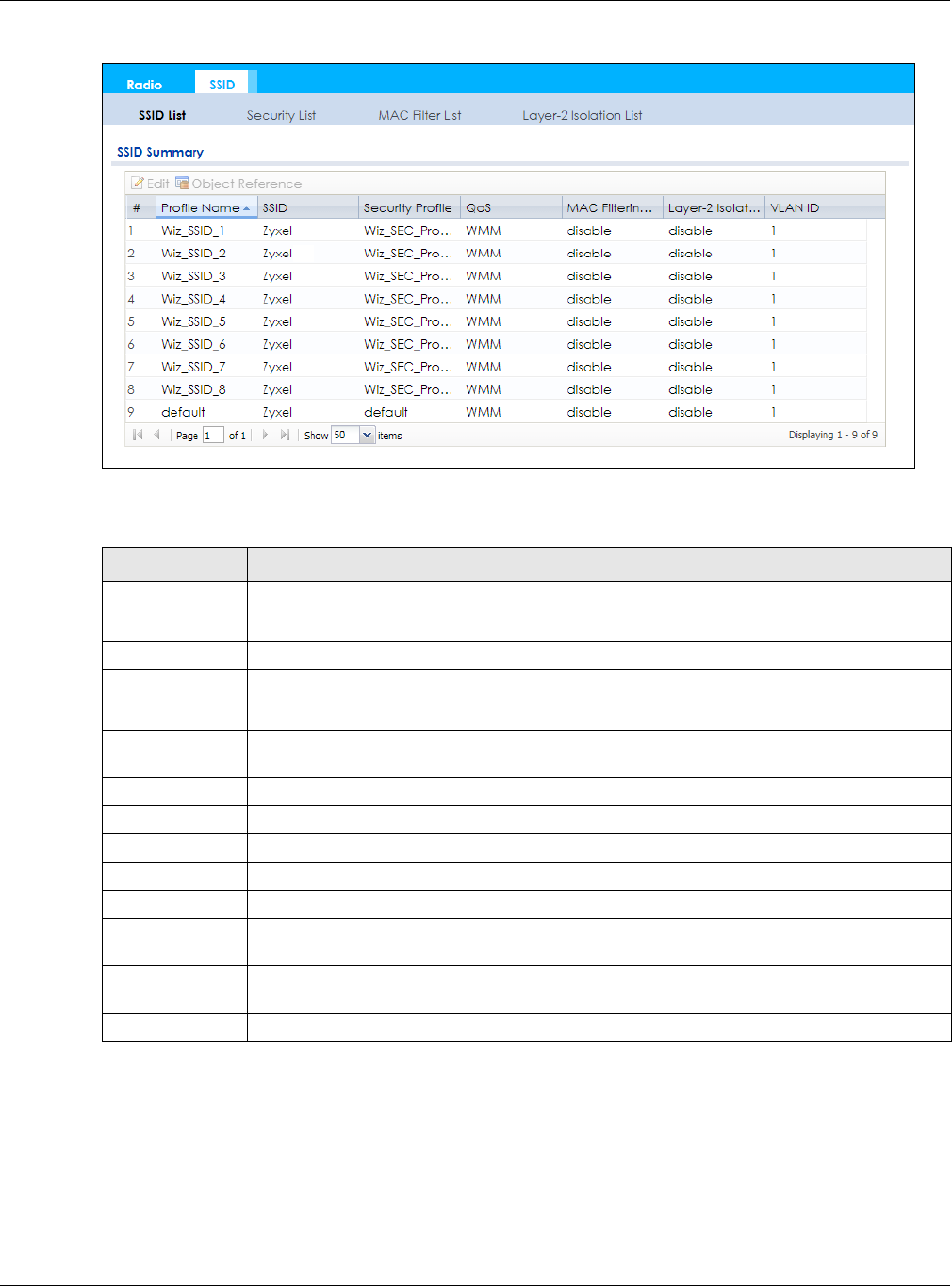
Chapter 10 AP Profile
NWA / WAC Series User’s Guide
115
Figure 70 Configuration > Object > AP Profile > SSID > SSID List (After wizard setup)
The following table describes the labels in this screen.
10.3.2 Add/Edit SSID Profile
This screen allows you to create a new SSID profile or edit an existing one. To access this screen, click the
Add button or select a SSID profile from the list and click the Edit button.
Table 51 Configuration > Object > AP Profile > SSID List
LABEL DESCRIPTION
Add Click this to add a new SSID profile.
This button is not available after you configure the NWA/WACusing the wizard.
Edit Click this to edit the selected SSID profile.
Remove Click this to remove the selected SSID profile.
This button is not available after you configure the NWA/WACusing the wizard.
Object
Reference
Click this to view which other objects are linked to the selected SSID profile (for example, radio
profile).
# This field is a sequential value, and it is not associated with a specific user.
Profile Name This field indicates the name assigned to the SSID profile.
SSID This field indicates the SSID name as it appears to wireless clients.
Security Profile This field indicates which (if any) security profile is associated with the SSID profile.
QoS This field indicates the QoS type associated with the SSID profile.
MAC Filtering
Profile
This field indicates which (if any) MAC filter Profile is associated with the SSID profile.
Layer-2 Isolation
Profile
This field indicates which (if any) layer-2 isolation Profile is associated with the SSID profile.
VLAN ID This field indicates the VLAN ID associated with the SSID profile.
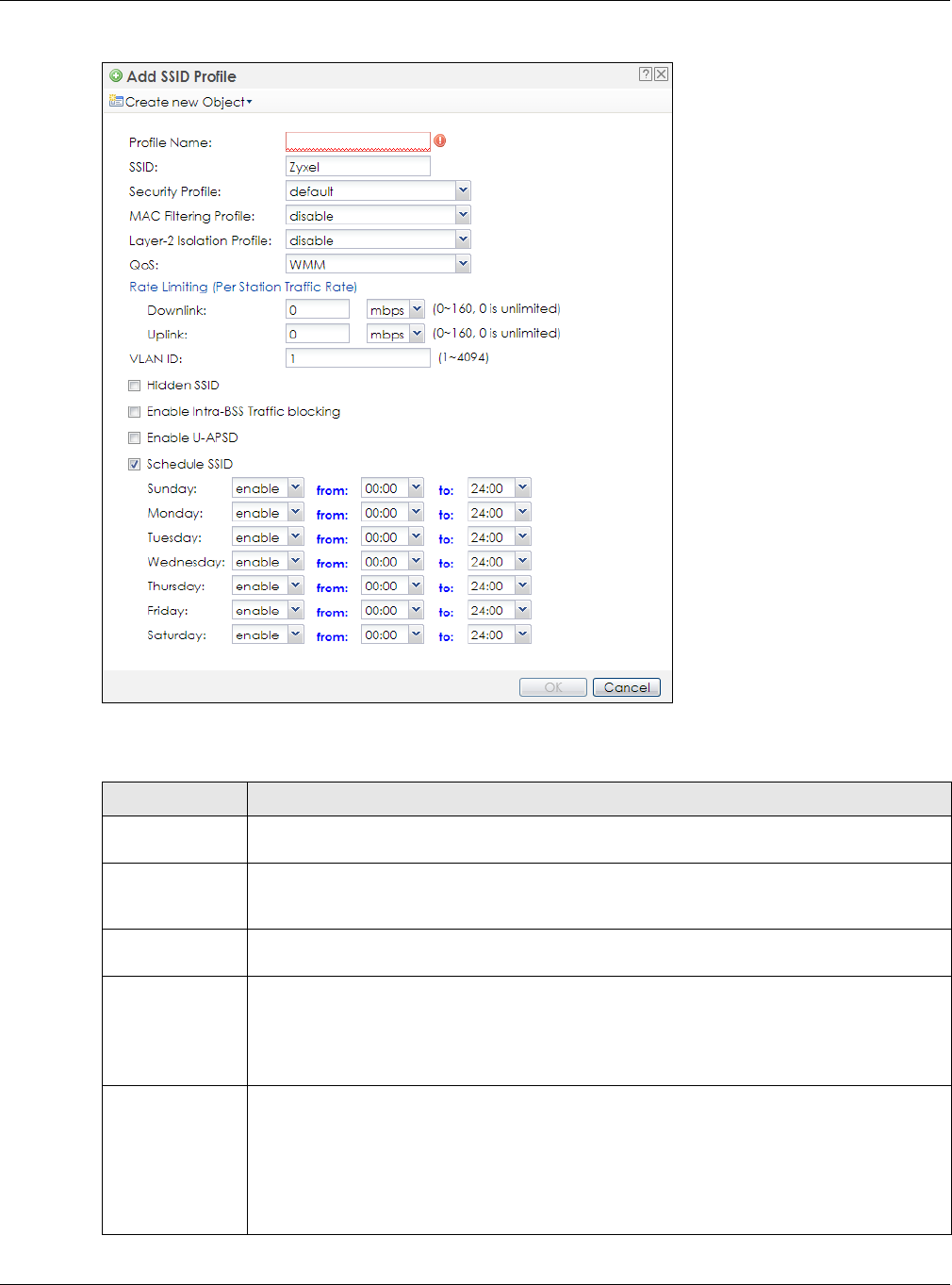
Chapter 10 AP Profile
NWA / WAC Series User’s Guide
116
Figure 71 Configuration > Object > AP Profile > Add/Edit SSID Profile
The following table describes the labels in this screen.
Table 52 Configuration > Object > AP Profile > Add/Edit SSID Profile
LABEL DESCRIPTION
Create new
Object
Select an object type from the list to create a new one associated with this SSID profile.
Profile Name Enter up to 31 alphanumeric characters for the profile name. This name is only visible in the
Web Configurator and is only for management purposes. Spaces and underscores are
allowed.
SSID Enter the SSID name for this profile. This is the name visible on the network to wireless clients.
Enter up to 32 characters, spaces and underscores are allowed.
Security Profile Select a security profile from this list to associate with this SSID. If none exist, you can use the
Create new Object menu to create one.
Note: It is highly recommended that you create security profiles for all of your SSIDs to
enhance your network security.
MAC Filtering
Profile
Select a MAC filtering profile from the list to associate with this SSID. If none exist, you can use
the Create new Object menu to create one.
MAC filtering allows you to limit the wireless clients connecting to your network through a
particular SSID by wireless client MAC addresses. Any clients that have MAC addresses not in
the MAC filtering profile of allowed addresses are denied connections.
The disable setting means no MAC filtering is used.

Chapter 10 AP Profile
NWA / WAC Series User’s Guide
117
Layer-2 Isolation
Profile
Select a layer-2 isolation profile from the list to associate with this SSID. If none exist, you can use
the Create new Object menu to create one.
Layer-2 isolation allows you to prevent wireless clients associated with your NWA/WAC from
communicating with other wireless clients, APs, computers or routers in a network.
The disable setting means no layer-2 isolation is used.
QoS Select a Quality of Service (QoS) access category to associate with this SSID. Access categories
minimize the delay of data packets across a wireless network. Certain categories, such as
video or voice, are given a higher priority due to the time sensitive nature of their data packets.
QoS access categories are as follows:
disable: Turns off QoS for this SSID. All data packets are treated equally and not tagged with
access categories.
WMM: Enables automatic tagging of data packets. The NWA/WAC assigns access categories
to the SSID by examining data as it passes through it and making a best guess effort. If
something looks like video traffic, for instance, it is tagged as such.
WMM_VOICE: All wireless traffic to the SSID is tagged as voice data. This is recommended if an
SSID is used for activities like placing and receiving VoIP phone calls.
WMM_VIDEO: All wireless traffic to the SSID is tagged as video data. This is recommended for
activities like video conferencing.
WMM_BEST_EFFORT: All wireless traffic to the SSID is tagged as “best effort,” meaning the data
travels the best route it can without displacing higher priority traffic. This is good for activities
that do not require the best bandwidth throughput, such as surfing the Internet.
WMM_BACKGROUND: All wireless traffic to the SSID is tagged as low priority or “background
traffic”, meaning all other access categories take precedence over this one. If traffic from an
SSID does not have strict throughput requirements, then this access category is recommended.
For example, an SSID that only has network printers connected to it.
Rate Limiting
Downlink Define the maximum incoming transmission data rate (either in mbps or kbps) on a perstation
basis.
Uplink Define the maximum outgoing transmission data rate (either in mbps or kbps) on a perstation
basis.
VLAN ID Enter a VLAN ID for the NWA/WAC to use to tag traffic originating from this SSID.
Hidden SSID Select this if you want to “hide” your SSID from wireless clients. This tells any wireless clients in the
vicinity of the AP using this SSID profile not to display its SSID name as a potential connection.
Not all wireless clients respect this flag and display it anyway.
When a SSID is “hidden” and a wireless client cannot see it, the only way you can connect to
the SSID is by manually entering the SSID name in your wireless connection setup screen(s)
(these vary by client, client connectivity software, and operating system).
Enable Intra-BSS
Traffic Blocking
Select this option to prevent crossover traffic from within the same SSID on the NWA/WAC.
Enable U-APSD Select this option to enable Unscheduled Automatic Power Save Delivery (U-APSD), which is
also known as WMM-Power Save. This helps increase battery life for battery-powered wireless
clients connected to the NWA/WAC using this SSID profile.
Schedule SSID Select this option and set whether the SSID is enabled or disabled on each day of the week.
You also need to select the hour and minute (in 24-hour format) to specify the time period of
each day during which the SSID is enabled/enabled.
OK Click OK to save your changes back to the NWA/WAC.
Cancel Click Cancel to exit this screen without saving your changes.
Table 52 Configuration > Object > AP Profile > Add/Edit SSID Profile (continued)
LABEL DESCRIPTION
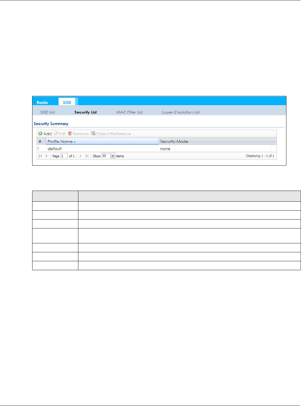
Chapter 10 AP Profile
NWA / WAC Series User’s Guide
118
10.4 Security List
This screen allows you to manage wireless security configurations that can be used by your SSIDs.
Wireless security is implemented strictly between the AP broadcasting the SSID and the stations that are
connected to it.
To access this screen click Configuration > Object > AP Profile > SSID > Security List.
Note: You can have a maximum of 32 security profiles on the NWA/WAC.
Figure 72 Configuration > Object > AP Profile > SSID > Security List
The following table describes the labels in this screen.
10.4.1 Add/Edit Security Profile
This screen allows you to create a new security profile or edit an existing one. To access this screen, click
the Add button or select a security profile from the list and click the Edit button.
Note: This screen’s options change based on the Security Mode selected. Only the default
screen is displayed here.
Table 53 Configuration > Object > AP Profile > SSID > Security List
LABEL DESCRIPTION
Add Click this to add a new security profile.
Edit Click this to edit the selected security profile.
Remove Click this to remove the selected security profile.
Object
Reference
Click this to view which other objects are linked to the selected security profile (for example,
SSID profile).
# This field is a sequential value, and it is not associated with a specific user.
Profile Name This field indicates the name assigned to the security profile.
Security Mode This field indicates this profile’s security mode (if any).
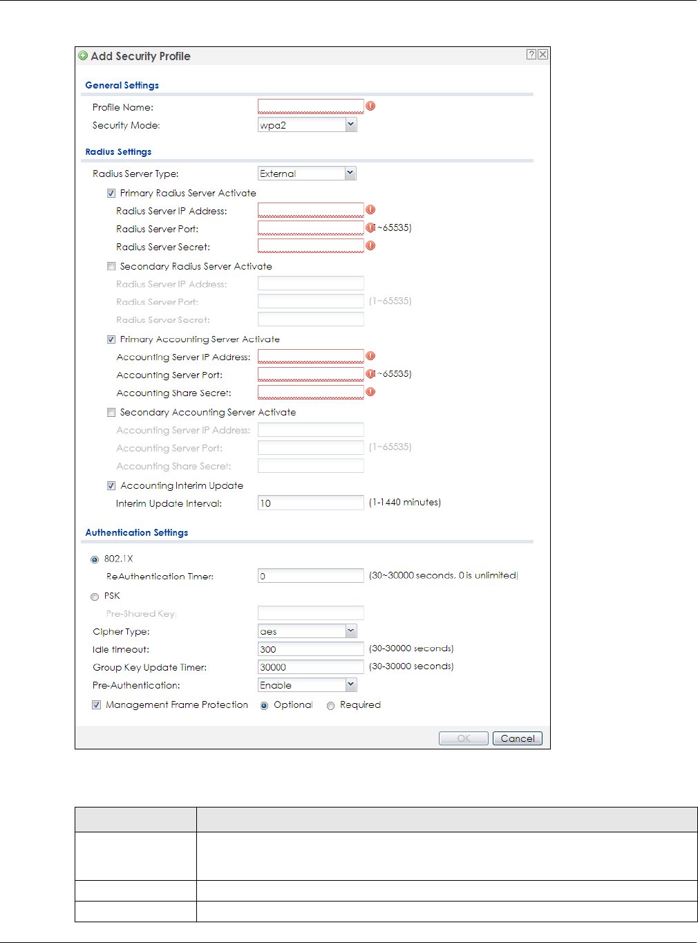
Chapter 10 AP Profile
NWA / WAC Series User’s Guide
119
Figure 73 Configuration > Object > AP Profile > SSID > Security List > Add/Edit Security Profile
The following table describes the labels in this screen.
Table 54 Configuration > Object > AP Profile > SSID > Security List > Add/Edit Security Profile
LABEL DESCRIPTION
Profile Name Enter up to 31 alphanumeric characters for the profile name. This name is only visible in the
Web Configurator and is only for management purposes. Spaces and underscores are
allowed.
Security Mode Select a security mode from the list: none, wep, wpa2, or wpa2-mix.
Radius Server Type This shows External and the NWA/WAC uses an external RADIUS server for authentication.

Chapter 10 AP Profile
NWA / WAC Series User’s Guide
120
Primary / Secondary
Radius Server
Activate
Select this to have the NWA/WAC use the specified RADIUS server.
Radius Server IP
Address Enter the IP address of the RADIUS server to be used for authentication.
Radius Server
Port Enter the port number of the RADIUS server to be used for authentication.
Radius Server
Secret Enter the shared secret password of the RADIUS server to be used for authentication.
Primary / Secondary
Accounting Server
Activate
Select the check box to enable user accounting through an external authentication server.
Accounting
Server IP Address Enter the IP address of the external accounting server in dotted decimal notation.
Accounting
Server Port Enter the port number of the external accounting server. The default port number is 1813.
You need not change this value unless your network administrator instructs you to do so with
additional information.
Accounting
Share Secret Enter a password (up to 128 alphanumeric characters) as the key to be shared between the
external accounting server and the NWA/WAC. The key must be the same on the external
accounting server and your NWA/WAC. The key is not sent over the network.
Accounting Interim
Update
This field is available only when you enable user accounting through an external
authentication server.
Select this to have the NWA/WAC send subscriber status updates to the accounting server
at the interval you specify.
Interim Update
Interval Specify the time interval for how often the NWA/WAC is to send a subscriber status update
to the accounting server.
802.1X Select this to enable 802.1x secure authentication.
ReAuthenticatio
n Timer Enter the interval (in seconds) between authentication requests. Enter a 0 for unlimited
requests.
WEP Authentication Settings
Idle Timeout Enter the idle interval (in seconds) that a client can be idle before authentication is
discontinued.
Authentication Type Select a WEP authentication method. Choices are Open or Share key. Share key is only
available if you are not using 802.1x.
Key Length Select the bit-length of the encryption key to be used in WEP connections.
If you select WEP-64:
• Enter 10 hexadecimal digits in the range of “A-F”, “a-f” and “0-9” (for example,
0x11AA22BB33) for each Key used.
or
• Enter 5 ASCII characters (case sensitive) ranging from “a-z”, “A-Z” and “0-9” (for
example, MyKey) for each Key used.
If you select WEP-128:
• Enter 26 hexadecimal digits in the range of “A-F”, “a-f” and “0-9” (for example,
0x00112233445566778899AABBCC) for each Key used.
or
• Enter 13 ASCII characters (case sensitive) ranging from “a-z”, “A-Z” and “0-9” (for
example, MyKey12345678) for each Key used.
Key 1~4 Based on your Key Length selection, enter the appropriate length hexadecimal or ASCII key.
WPA2/WPA2-Mix Authentication Settings
Table 54 Configuration > Object > AP Profile > SSID > Security List > Add/Edit Security Profile (continued)
LABEL DESCRIPTION

Chapter 10 AP Profile
NWA / WAC Series User’s Guide
121
10.5 MAC Filter List
This screen allows you to create and manage security configurations that can be used by your SSIDs. To
access this screen click Configuration > Object > AP Profile > SSID > MAC Filter List.
Note: You can have a maximum of 32 MAC filtering profiles on the NWA/WAC.
PSK This field is available when you select the wpa2, or wpa2-mix security mode.
Select this option to use a Pre-Shared Key with WPA2 encryption.
Pre-Shared Key Enter a pre-shared key of between 8 and 63 case-sensitive ASCII characters (including
spaces and symbols) or 64 hexadecimal characters.
Cipher Type Select an encryption cipher type from the list.
•auto - This automatically chooses the best available cipher based on the cipher in use
by the wireless client that is attempting to make a connection.
•aes - This is the Advanced Encryption Standard encryption method. It is a more recent
development over TKIP and considerably more robust. Not all wireless clients may
support this.
Idle Timeout Enter the interval (in seconds) that a client can be idle before authentication is
discontinued.
Group Key Update
Timer
Enter the interval (in seconds) at which the AP updates the group WPA2 encryption key.
Management
Frame Protection
This field is available only when you select wpa2 in the Security Mode field and set Cipher
Type to aes.
Data frames in 802.11 WLANs can be encrypted and authenticated with WEP, WPA or
WPA2. But 802.11 management frames, such as beacon/probe response, association
request, association response, de-authentication and disassociation are always
unauthenticated and unencrypted. IEEE 802.11w Protected Management Frames allows
APs to use the existing security mechanisms (encryption and authentication methods
defined in IEEE 802.11i WPA/WPA2) to protect management frames. This helps prevent
wireless DoS attacks.
Select the check box to enable management frame protection (MFP) to add security to
802.11 management frames.
Select Optional if you do not require the wireless clients to support MFP. Management
frames will be encrypted if the clients support MFP.
Select Required and wireless clients must support MFP in order to join the NWA/WAC’s
wireless network.
OK Click OK to save your changes back to the NWA/WAC.
Cancel Click Cancel to exit this screen without saving your changes.
Table 54 Configuration > Object > AP Profile > SSID > Security List > Add/Edit Security Profile (continued)
LABEL DESCRIPTION
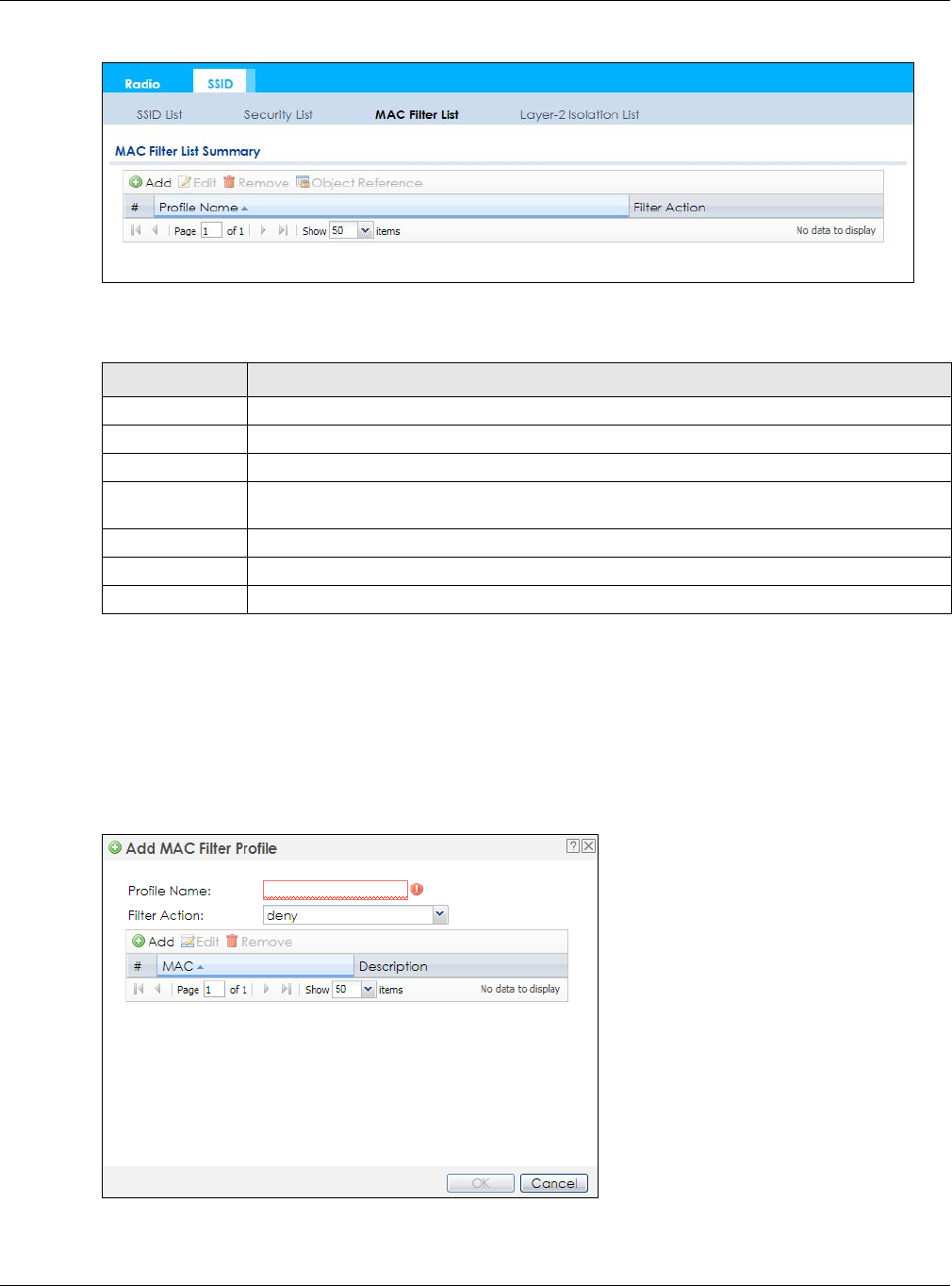
Chapter 10 AP Profile
NWA / WAC Series User’s Guide
122
Figure 74 Configuration > Object > AP Profile > SSID > MAC Filter List
The following table describes the labels in this screen.
10.5.1 Add/Edit MAC Filter Profile
This screen allows you to create a new MAC filtering profile or edit an existing one. To access this screen,
click the Add button or select a MAC filter profile from the list and click the Edit button.
Note: Each MAC filtering profile can include a maximum of 512 MAC addresses.
Figure 75 Configuration > Object > AP Profile > SSID > MAC Filter List > Add/Edit MAC Filter Profile
Table 55 Configuration > Object > AP Profile > SSID > MAC Filter List
LABEL DESCRIPTION
Add Click this to add a new MAC filtering profile.
Edit Click this to edit the selected MAC filtering profile.
Remove Click this to remove the selected MAC filtering profile.
Object
Reference
Click this to view which other objects are linked to the selected MAC filtering profile (for
example, SSID profile).
# This field is a sequential value, and it is not associated with a specific user.
Profile Name This field indicates the name assigned to the MAC filtering profile.
Filter Action This field indicates this profile’s filter action (if any).
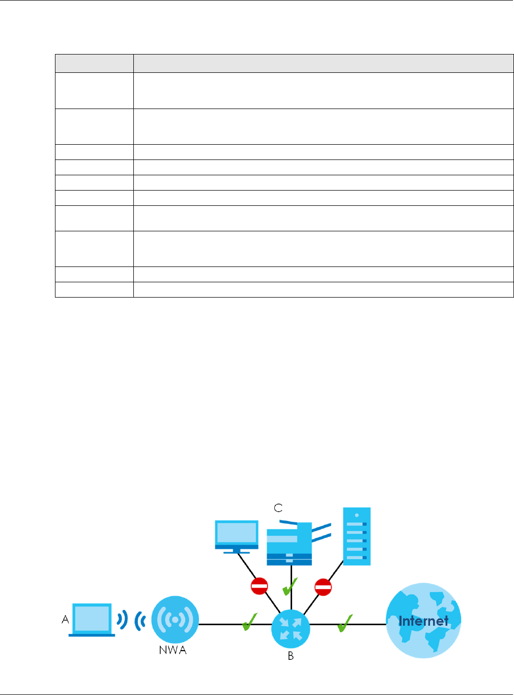
Chapter 10 AP Profile
NWA / WAC Series User’s Guide
123
The following table describes the labels in this screen.
10.6 Layer-2 Isolation List
Layer-2 isolation is used to prevent wireless clients associated with your NWA/WAC from communicating
with other wireless clients, APs, computers or routers in a network.
In the following example, layer-2 isolation is enabled on the NWA/WAC to allow a guest wireless client
(A) to access the main network router (B). The router provides access to the Internet and the network
printer (C) while preventing the client from accessing other computers and servers on the network. The
client can communicate with other wireless clients only if Intra-BSS Traffic blocking is disabled.
Note: Intra-BSS Traffic Blocking is activated when you enable layer-2 isolation.
Figure 76 Layer-2 Isolation Application
Table 56 Configuration > Object > AP Profile > SSID > MAC Filter List > Add/Edit MAC Filter Profile
LABEL DESCRIPTION
Profile Name Enter up to 31 alphanumeric characters for the profile name. This name is only visible in the
Web Configurator and is only for management purposes. Spaces and underscores are
allowed.
Filter Action Select allow to permit the wireless client with the MAC addresses in this profile to connect to the
network through the associated SSID; select deny to block the wireless clients with the specified
MAC addresses.
Add Click this to add a MAC address to the profile’s list.
Edit Click this to edit the selected MAC address in the profile’s list.
Remove Click this to remove the selected MAC address from the profile’s list.
# This field is a sequential value, and it is not associated with a specific user.
MAC This field specifies a MAC address associated with this profile. You can click the MAC address to
make it editable.
Description This field displays a description for the MAC address associated with this profile. You can click
the description to make it editable. Enter up to 60 characters, spaces and underscores
allowed.
OK Click OK to save your changes back to the NWA/WAC.
Cancel Click Cancel to exit this screen without saving your changes.
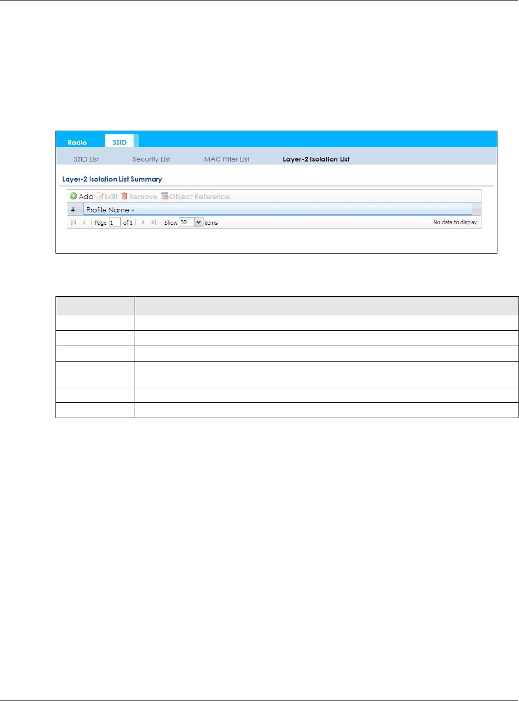
Chapter 10 AP Profile
NWA / WAC Series User’s Guide
124
MAC addresses that are not listed in the layer-2 isolation table are blocked from communicating with
the NWA/WAC’s wireless clients except for broadcast packets. Layer-2 isolation does not check the
traffic between wireless clients that are associated with the same AP. Intra-BSS traffic allows wireless
clients associated with the same AP to communicate with each other.
This screen allows you to specify devices you want the users on your wireless networks to access. To
access this screen click Configuration > Object > AP Profile > SSID > Layer-2 Isolation List.
Figure 77 Configuration > Object > AP Profile > SSID > Layer-2 Isolation List
The following table describes the labels in this screen.
10.6.1 Add/Edit Layer-2 Isolation Profile
This screen allows you to create a new layer-2 isolation profile or edit an existing one. To access this
screen, click the Add button or select a layer-2 isolation profile from the list and click the Edit button.
Note: You need to know the MAC address of each wireless client, AP, computer or router that
you want to allow to communicate with the NWA/WAC's wireless clients.
Table 57 Configuration > Object > AP Profile > SSID > Layer-2 Isolation List
LABEL DESCRIPTION
Add Click this to add a new MAC filtering profile.
Edit Click this to edit the selected MAC filtering profile.
Remove Click this to remove the selected MAC filtering profile.
Object
Reference
Click this to view which other objects are linked to the selected MAC filtering profile (for
example, SSID profile).
# This field is a sequential value, and it is not associated with a specific user.
Profile Name This field indicates the name assigned to the layer-2 isolation profile.
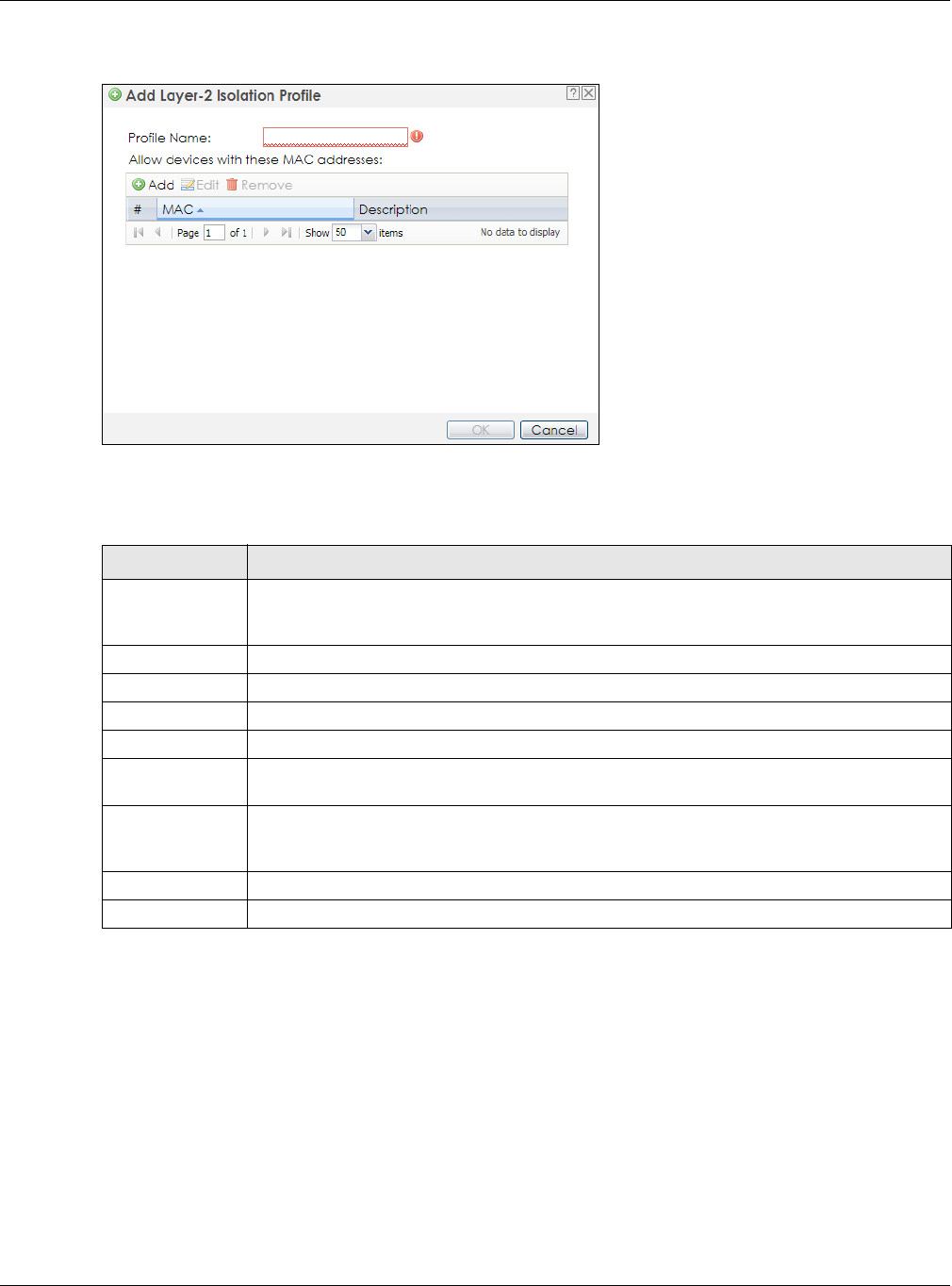
Chapter 10 AP Profile
NWA / WAC Series User’s Guide
125
Figure 78 Configuration > Object > AP Profile > SSID > Layer-2 Isolation List > Add/Edit Layer-2 Isolation
Profile
The following table describes the labels in this screen.
Table 58 Configuration > Object > AP Profile > SSID > Layer-2 Isolation List > Add/Edit Layer-2 Isolation
Profile
LABEL DESCRIPTION
Profile Name Enter up to 31 alphanumeric characters for the profile name. This name is only visible in the
Web Configurator and is only for management purposes. Spaces and underscores are
allowed.
Add Click this to add a MAC address to the profile’s list.
Edit Click this to edit the selected MAC address in the profile’s list.
Remove Click this to remove the selected MAC address from the profile’s list.
# This field is a sequential value, and it is not associated with a specific user.
MAC This field specifies a MAC address associated with this profile. You can click the MAC address to
make it editable.
Description This field displays a description for the MAC address associated with this profile. You can click
the description to make it editable. Enter up to 60 characters, spaces and underscores
allowed.
OK Click OK to save your changes back to the NWA/WAC.
Cancel Click Cancel to exit this screen without saving your changes.
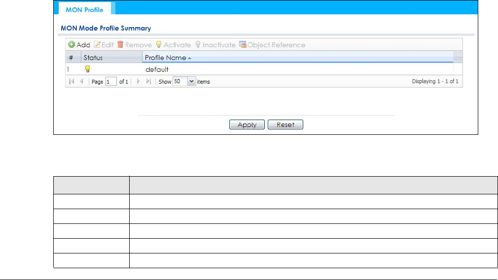
NWA / WAC Series User’s Guide
126
CHAPTER 11
MON Profile
11.1 Overview
This screen allows you to set up monitor mode configurations that allow your NWA/WAC to scan for
other wireless devices in the vicinity. Once detected, you can use the Wireless > MON Mode screen
(Section 7.3 on page 88) to classify them as either rogue or friendly.
Not all NWA/WACs support monitor mode and rogue APs detection.
11.1.1 What You Can Do in this Chapter
The MON Profile screen (Section 11.2 on page 126) creates preset monitor mode configurations that can
be used by the NWA/WAC.
11.2 MON Profile
This screen allows you to create monitor mode configurations that can be used by the APs. To access
this screen, log into the Web Configurator, and click Configuration > Object > MON Profile.
Figure 79 Configuration > Object > MON Profile
The following table describes the labels in this screen.
Table 59 Configuration > Object > MON Profile
LABEL DESCRIPTION
Add Click this to add a new monitor mode profile.
Edit Click this to edit the selected monitor mode profile.
Remove Click this to remove the selected monitor mode profile.
Activate To turn on an entry, select it and click Activate.
Inactivate To turn off an entry, select it and click Inactivate.
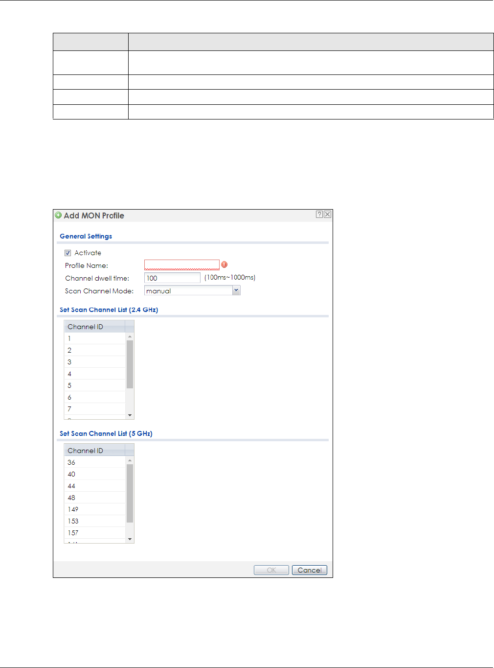
Chapter 11 MON Profile
NWA / WAC Series User’s Guide
127
11.2.1 Add/Edit MON Profile
This screen allows you to create a new monitor mode profile or edit an existing one. To access this
screen, click the Add button or select and existing monitor mode profile and click the Edit button.
Figure 80 Configuration > Object > MON Profile > Add/Edit MON Profile
Object
Reference
Click this to view which other objects are linked to the selected monitor mode profile (for
example, an AP management profile).
# This field is a sequential value, and it is not associated with a specific profile.
Status This field shows whether or not the entry is activated.
Profile Name This field indicates the name assigned to the monitor profile.
Table 59 Configuration > Object > MON Profile (continued)
LABEL DESCRIPTION

Chapter 11 MON Profile
NWA / WAC Series User’s Guide
128
The following table describes the labels in this screen.
11.3 Technical Reference
The following section contains additional technical information about the features described in this
chapter.
Rogue APs
Rogue APs are wireless access points operating in a network’s coverage area that are not under the
control of the network’s administrators, and can open up holes in a network’s security. Attackers can
take advantage of a rogue AP’s weaker (or non-existent) security to gain access to the network, or set
up their own rogue APs in order to capture information from wireless clients. If a scan reveals a rogue AP,
you can use commercially-available software to physically locate it.
Table 60 Configuration > Object > MON Profile > Add/Edit MON Profile
LABEL DESCRIPTION
Activate Select this to activate this monitor mode profile.
Profile Name This field indicates the name assigned to the monitor mode profile.
Channel dwell time Enter the interval (in milliseconds) before the NWA/WAC switches to another channel for
monitoring.
Scan Channel Mode Select auto to have the NWA/WAC switch to the next sequential channel once the
Channel dwell time expires.
Select manual to set specific channels through which to cycle sequentially when the
Channel dwell time expires. Selecting this options makes the Scan Channel List options
available.
Set Scan Channel List
(2.4 GHz)
Select one or more than one channel to have the NWA/WAC using this profile scan the
channel(s) when Scan Channel Mode is set to manual.
These channels are limited to the 2.4 GHz range (802.11 b/g/n).
Set Scan Channel List
(5 GHz)
Select one or more than one channel to have the NWA/WAC using this profile scan the
channel(s) when Scan Channel Mode is set to manual.
These channels are limited to the 5 GHz range (802.11 a/n). Not all NWA/WACs support
both 2.4 GHz and 5 GHz frequency bands.
OK Click OK to save your changes back to the NWA/WAC.
Cancel Click Cancel to exit this screen without saving your changes.
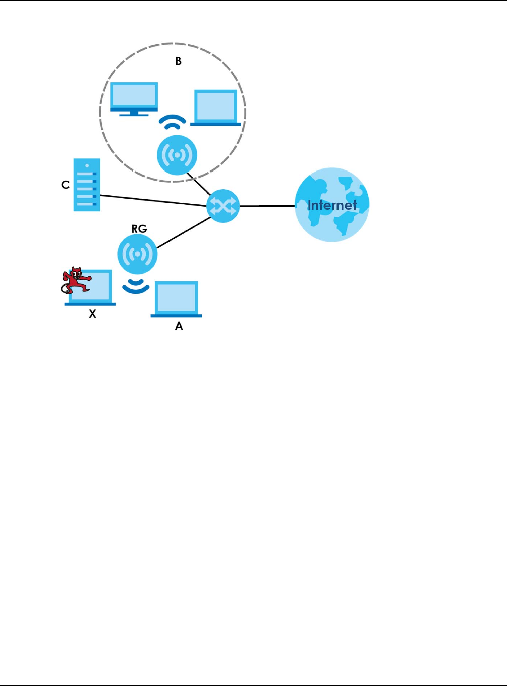
Chapter 11 MON Profile
NWA / WAC Series User’s Guide
129
Figure 81 Rogue AP Example
In the example above, a corporate network’s security is compromised by a rogue AP (RG) set up by an
employee at his workstation in order to allow him to connect his notebook computer wirelessly (A). The
company’s legitimate wireless network (the dashed ellipse B) is well-secured, but the rogue AP uses
inferior security that is easily broken by an attacker (X) running readily available encryption-cracking
software. In this example, the attacker now has access to the company network, including sensitive
data stored on the file server (C).
Friendly APs
If you have more than one AP in your wireless network, you should also configure a list of “friendly” APs.
Friendly APs are other wireless access points that are detected in your network, as well as any others that
you know are not a threat (those from recognized networks, for example). It is recommended that you
export (save) your list of friendly APs often, especially if you have a network with a large number of
access points.
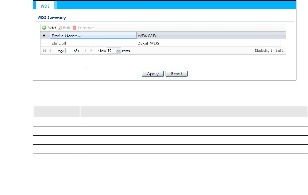
NWA / WAC Series User’s Guide
130
CHAPTER 12
WDS Profile
12.1 Overview
This chapter shows you how to configure WDS (Wireless Distribution System) profiles for the NWA/WAC to
form a WDS with other APs.
12.1.1 What You Can Do in this Chapter
The WDS Profile screen (Section 12.2 on page 130) creates preset WDS configurations that can be used
by the NWA/WAC.
12.2 WDS Profile
This screen allows you to manage and create WDS profiles that can be used by the APs. To access this
screen, click Configuration > Object > WDS Profile.
Figure 82 Configuration > Object > WDS Profile
The following table describes the labels in this screen.
Table 61 Configuration > Object > WDS Profile
LABEL DESCRIPTION
Add Click this to add a new profile.
Edit Click this to edit the selected profile.
Remove Click this to remove the selected profile.
# This field is a sequential value, and it is not associated with a specific profile.
Profile Name This field indicates the name assigned to the profile.
WDS SSID This field shows the SSID specified in this WDS profile.
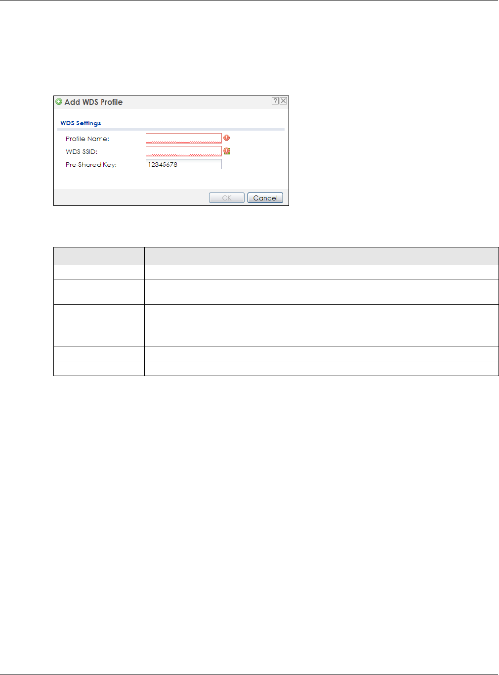
Chapter 12 WDS Profile
NWA / WAC Series User’s Guide
131
12.2.1 Add/Edit WDS Profile
This screen allows you to create a new WDS profile or edit an existing one. To access this screen, click the
Add button or select and existing profile and click the Edit button.
Figure 83 Configuration > Object > WDS Profile > Add/Edit WDS Profile
The following table describes the labels in this screen.
Table 62 Configuration > Object > WDS Profile > Add/Edit WDS Profile
LABEL DESCRIPTION
Profile Name Enter up to 31 alphanumeric characters for the profile name.
WDS SSID Enter the SSID with which you want the NWA/WAC to connect to a root AP or repeater to
form a WDS.
Pre-Shared Key Enter a pre-shared key of between 8 and 63 case-sensitive ASCII characters (including
spaces and symbols) or 64 hexadecimal characters.
The key is used to encrypt the traffic between the APs.
OK Click OK to save your changes back to the NWA/WAC.
Cancel Click Cancel to exit this screen without saving your changes.

NWA / WAC Series User’s Guide
132
CHAPTER 13
Certificates
13.1 Overview
The NWA/WAC can use certificates (also called digital IDs) to authenticate users. Certificates are based
on public-private key pairs. A certificate contains the certificate owner’s identity and public key.
Certificates provide a way to exchange public keys for use in authentication.
13.1.1 What You Can Do in this Chapter
• The My Certificates screens (Section 13.2 on page 135) generate and export self-signed certificates or
certification requests and import the NWA/WAC’s CA-signed certificates.
• The Trusted Certificates screens (Section 13.3 on page 142) save CA certificates and trusted remote
host certificates to the NWA/WAC. The NWA/WAC trusts any valid certificate that you have imported
as a trusted certificate. It also trusts any valid certificate signed by any of the certificates that you
have imported as a trusted certificate.
13.1.2 What You Need to Know
The following terms and concepts may help as you read this chapter.
When using public-key cryptology for authentication, each host has two keys. One key is public and can
be made openly available. The other key is private and must be kept secure.
These keys work like a handwritten signature (in fact, certificates are often referred to as “digital
signatures”). Only you can write your signature exactly as it should look. When people know what your
signature looks like, they can verify whether something was signed by you, or by someone else. In the
same way, your private key “writes” your digital signature and your public key allows people to verify
whether data was signed by you, or by someone else.
This process works as follows:
1Tim wants to send a message to Jenny. He needs her to be sure that it comes from him, and that the
message content has not been altered by anyone else along the way. Tim generates a public key pair
(one public key and one private key).
2Tim keeps the private key and makes the public key openly available. This means that anyone who
receives a message seeming to come from Tim can read it and verify whether it is really from him or not.
3Tim uses his private key to sign the message and sends it to Jenny.
4Jenny receives the message and uses Tim’s public key to verify it. Jenny knows that the message is from
Tim, and that although other people may have been able to read the message, no-one can have
altered it (because they cannot re-sign the message with Tim’s private key).

Chapter 13 Certificates
NWA / WAC Series User’s Guide
133
5Additionally, Jenny uses her own private key to sign a message and Tim uses Jenny’s public key to verify
the message.
The NWA/WAC uses certificates based on public-key cryptology to authenticate users attempting to
establish a connection, not to encrypt the data that you send after establishing a connection. The
method used to secure the data that you send through an established connection depends on the
type of connection.
The certification authority uses its private key to sign certificates. Anyone can then use the certification
authority’s public key to verify the certificates.
A certification path is the hierarchy of certification authority certificates that validate a certificate. The
NWA/WAC does not trust a certificate if any certificate on its path has expired or been revoked.
Certification authorities maintain directory servers with databases of valid and revoked certificates. A
directory of certificates that have been revoked before the scheduled expiration is called a CRL
(Certificate Revocation List). The NWA/WAC can check a peer’s certificate against a directory server’s
list of revoked certificates. The framework of servers, software, procedures and policies that handles keys
is called PKI (public-key infrastructure).
Advantages of Certificates
Certificates offer the following benefits.
• The NWA/WAC only has to store the certificates of the certification authorities that you decide to
trust, no matter how many devices you need to authenticate.
• Key distribution is simple and very secure since you can freely distribute public keys and you never
need to transmit private keys.
Self-signed Certificates
You can have the NWA/WAC act as a certification authority and sign its own certificates.
Factory Default Certificate
The NWA/WAC generates its own unique self-signed certificate when you first turn it on. This certificate is
referred to in the GUI as the factory default certificate.
Certificate File Formats
Any certificate that you want to import has to be in one of these file formats:
• Binary X.509: This is an ITU-T recommendation that defines the formats for X.509 certificates.
• PEM (Base-64) encoded X.509: This Privacy Enhanced Mail format uses lowercase letters, uppercase
letters and numerals to convert a binary X.509 certificate into a printable form.
• Binary PKCS#7: This is a standard that defines the general syntax for data (including digital signatures)
that may be encrypted. A PKCS #7 file is used to transfer a public key certificate. The private key is not
included. The NWA/WAC currently allows the importation of a PKS#7 file that contains a single
certificate.
• PEM (Base-64) encoded PKCS#7: This Privacy Enhanced Mail (PEM) format uses lowercase letters,
uppercase letters and numerals to convert a binary PKCS#7 certificate into a printable form.
Chapter 13 Certificates
NWA / WAC Series User’s Guide
134
• Binary PKCS#12: This is a format for transferring public key and private key certificates.The private key
in a PKCS #12 file is within a password-encrypted envelope. The file’s password is not connected to
your certificate’s public or private passwords. Exporting a PKCS #12 file creates this and you must
provide it to decrypt the contents when you import the file into the NWA/WAC.
Note: Be careful not to convert a binary file to text during the transfer process. It is easy for this
to occur since many programs use text files by default.
13.1.3 Verifying a Certificate
Before you import a trusted certificate into the NWA/WAC, you should verify that you have the correct
certificate. You can do this using the certificate’s fingerprint. A certificate’s fingerprint is a message
digest calculated using the MD5 or SHA1 algorithm. The following procedure describes how to check a
certificate’s fingerprint to verify that you have the actual certificate.
1Browse to where you have the certificate saved on your computer.
2Make sure that the certificate has a “.cer” or “.crt” file name extension.
3Double-click the certificate’s icon to open the Certificate window. Click the Details tab and scroll down
to the Thumbprint Algorithm and Thumbprint fields.
4Use a secure method to verify that the certificate owner has the same information in the Thumbprint
Algorithm and Thumbprint fields. The secure method may very based on your situation. Possible
examples would be over the telephone or through an HTTPS connection.
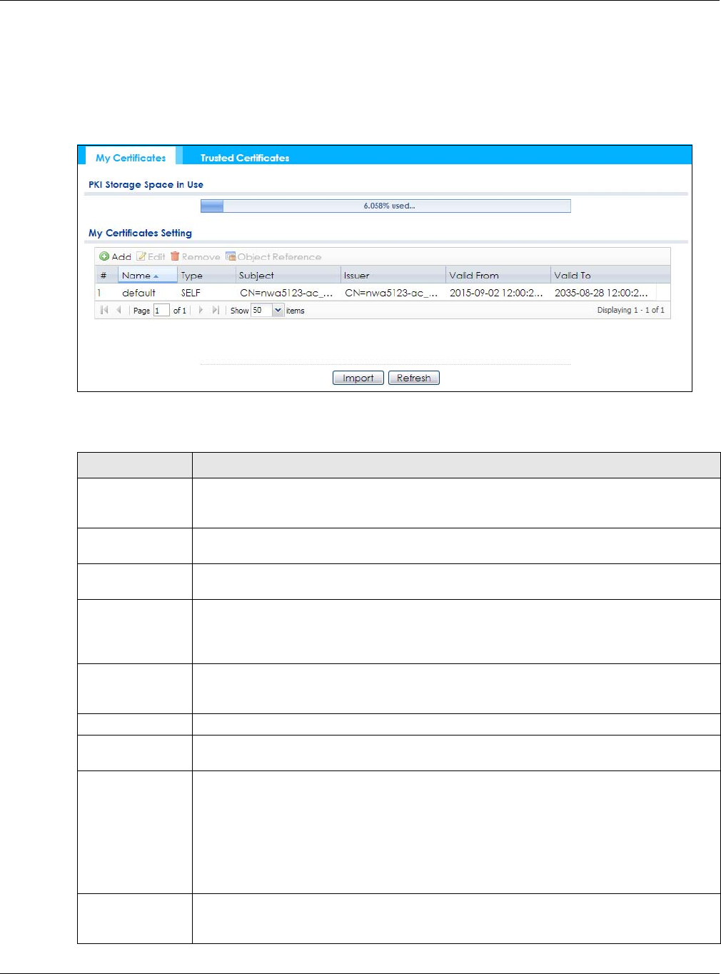
Chapter 13 Certificates
NWA / WAC Series User’s Guide
135
13.2 My Certificates
Click Configuration > Object > Certificate > My Certificates to open this screen. This is the NWA/WAC’s
summary list of certificates and certification requests.
Figure 84 Configuration > Object > Certificate > My Certificates
The following table describes the labels in this screen.
Table 63 Configuration > Object > Certificate > My Certificates
LABEL DESCRIPTION
PKI Storage Space
in Use
This bar displays the percentage of the NWA/WAC’s PKI storage space that is currently in use.
When the storage space is almost full, you should consider deleting expired or unnecessary
certificates before adding more certificates.
Add Click this to go to the screen where you can have the NWA/WAC generate a certificate or a
certification request.
Edit Double-click an entry or select it and click Edit to open a screen with an in-depth list of
information about the certificate.
Remove The NWA/WAC keeps all of your certificates unless you specifically delete them. Uploading a
new firmware or default configuration file does not delete your certificates. To remove an
entry, select it and click Remove. The NWA/WAC confirms you want to remove it before doing
so. Subsequent certificates move up by one when you take this action.
Object Reference You cannot delete certificates that any of the NWA/WAC’s features are configured to use.
Select an entry and click Object Reference to open a screen that shows which settings use
the entry.
# This field displays the certificate index number. The certificates are listed in alphabetical order.
Name This field displays the name used to identify this certificate. It is recommended that you give
each certificate a unique name.
Type This field displays what kind of certificate this is.
REQ represents a certification request and is not yet a valid certificate. Send a certification
request to a certification authority, which then issues a certificate. Use the My Certificate
Import screen to import the certificate and replace the request.
SELF represents a self-signed certificate.
CERT represents a certificate issued by a certification authority.
Subject This field displays identifying information about the certificate’s owner, such as CN (Common
Name), OU (Organizational Unit or department), O (Organization or company) and C
(Country). It is recommended that each certificate have unique subject information.
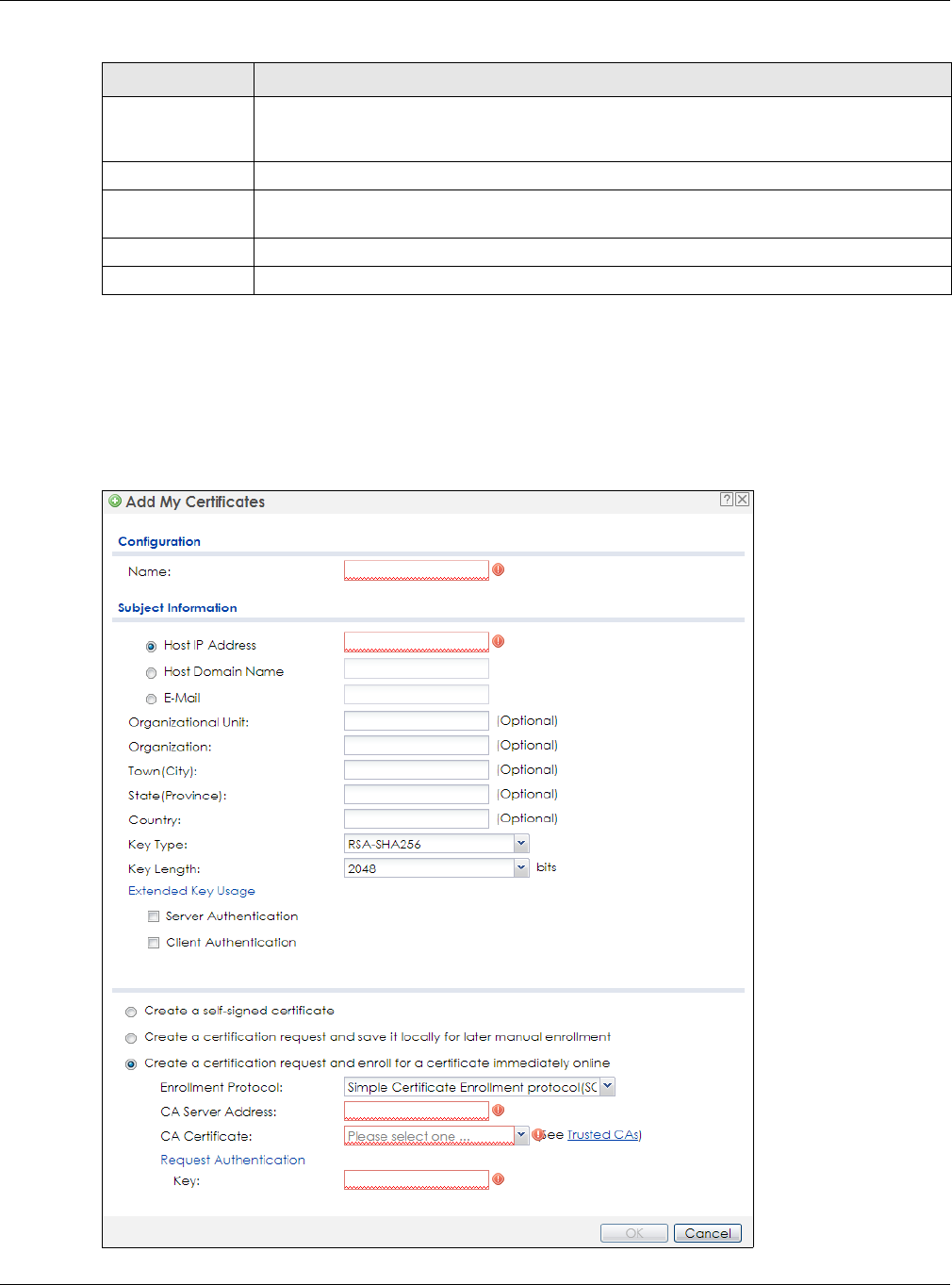
Chapter 13 Certificates
NWA / WAC Series User’s Guide
136
13.2.1 Add My Certificates
Click Configuration > Object > Certificate > My Certificates and then the Add icon to open the Add My
Certificates screen. Use this screen to have the NWA/WAC create a self-signed certificate, enroll a
certificate with a certification authority or generate a certification request.
Figure 85 Configuration > Object > Certificate > My Certificates > Add
Issuer This field displays identifying information about the certificate’s issuing certification authority,
such as a common name, organizational unit or department, organization or company and
country. With self-signed certificates, this is the same information as in the Subject field.
Valid From This field displays the date that the certificate becomes applicable.
Valid To This field displays the date that the certificate expires. The text displays in red and includes an
Expired! message if the certificate has expired.
Import Click Import to open a screen where you can save a certificate to the NWA/WAC.
Refresh Click Refresh to display the current validity status of the certificates.
Table 63 Configuration > Object > Certificate > My Certificates (continued)
LABEL DESCRIPTION

Chapter 13 Certificates
NWA / WAC Series User’s Guide
137
The following table describes the labels in this screen.
Table 64 Configuration > Object > Certificate > My Certificates > Add
LABEL DESCRIPTION
Name Type a name to identify this certificate. You can use up to 31 alphanumeric and
;‘~!@#$%^&()_+[]{}’,.=- characters.
Subject Information Use these fields to record information that identifies the owner of the certificate. You do
not have to fill in every field, although you must specify a Host IP Address, Host Domain
Name, or E-Mail. The certification authority may add fields (such as a serial number) to the
subject information when it issues a certificate. It is recommended that each certificate
have unique subject information.
Select a radio button to identify the certificate’s owner by IP address, domain name or e-
mail address. Type the IP address (in dotted decimal notation), domain name or e-mail
address in the field provided. The domain name or e-mail address is for identification
purposes only and can be any string.
A domain name can be up to 255 characters. You can use alphanumeric characters, the
hyphen and periods.
An e-mail address can be up to 63 characters. You can use alphanumeric characters, the
hyphen, the @ symbol, periods and the underscore.
Organizational Unit Identify the organizational unit or department to which the certificate owner belongs. You
can use up to 31 characters. You can use alphanumeric characters, the hyphen and the
underscore.
Organization Identify the company or group to which the certificate owner belongs. You can use up to
31 characters. You can use alphanumeric characters, the hyphen and the underscore.
Town (City) Identify the town or city where the certificate owner is located. You can use up to 31
characters. You can use alphanumeric characters, the hyphen and the underscore.
State (Province) Identify the state or province where the certificate owner is located. You can use up to 31
characters. You can use alphanumeric characters, the hyphen and the underscore.
Country Identify the nation where the certificate owner is located. You can use up to 31
characters. You can use alphanumeric characters, the hyphen and the underscore.
Key Type The NWA/WAC uses the RSA (Rivest, Shamir and Adleman) public-key encryption
algorithm. SHA1 (Secure Hash Algorithm) and SHA2 are hash algorithms used to
authenticate packet data. SHA2-256 or SHA2-512 are part of the SHA2 set of
cryptographic functions and they are considered even more secure than SHA1.
Select a key type from RSA-SHA256 and RSA-SHA512.
Key Length Select a number from the drop-down list box to determine how many bits the key should
use (1024 to 2048). The longer the key, the more secure it is. A longer key also uses more PKI
storage space.
Extended Key Usage Select Server Authentication to allow a web server to send clients the certificate to
authenticate itself.
Select Client Authentication to use the certificate’s key to authenticate clients to the
secure gateway.
These radio buttons deal with how and when the certificate is to be generated.
Create a self-signed
certificate
Select this to have the NWA/WAC generate the certificate and act as the Certification
Authority (CA) itself. This way you do not need to apply to a certification authority for
certificates.
Create a certification
request and save it
locally for later
manual enrollment
Select this to have the NWA/WAC generate and store a request for a certificate. Use the
My Certificate Edit screen to view the certification request and copy it to send to the
certification authority.
Copy the certification request from the My Certificate Edit screen and then send it to the
certification authority.

Chapter 13 Certificates
NWA / WAC Series User’s Guide
138
If you configured the Add My Certificates screen to have the NWA/WAC enroll a certificate and the
certificate enrollment is not successful, you see a screen with a Return button that takes you back to the
Add My Certificates screen. Click Return and check your information in the Add My Certificates screen.
Make sure that the certification authority information is correct and that your Internet connection is
working properly if you want the NWA/WAC to enroll a certificate online.
13.2.2 Edit My Certificates
Click Configuration > Object > Certificate > My Certificates and then the Edit icon to open the My
Certificate Edit screen. You can use this screen to view in-depth certificate information and change the
certificate’s name.
Create a certification
request and enroll for
a certificate
immediately online
Select this to have the NWA/WAC generate a request for a certificate and apply to a
certification authority for a certificate.
You must have the certification authority’s certificate already imported in the Trusted
Certificates screen.
When you select this option, you must select the certification authority’s enrollment
protocol and the certification authority’s certificate from the drop-down list boxes and
enter the certification authority’s server address. You also need to fill in the Reference
Number and Key if the certification authority requires them.
Enrollment Protocol This field applies when you select Create a certification request and enroll for a certificate
immediately online. Select the certification authority’s enrollment protocol from the drop-
down list box.
Simple Certificate Enrollment Protocol (SCEP) is a TCP-based enrollment protocol that was
developed by VeriSign and Cisco.
Certificate Management Protocol (CMP) is a TCP-based enrollment protocol that was
developed by the Public Key Infrastructure X.509 working group of the Internet
Engineering Task Force (IETF) and is specified in RFC 2510.
CA Server Address This field applies when you select Create a certification request and enroll for a certificate
immediately online. Enter the IP address (or URL) of the certification authority server.
For a URL, you can use up to 511 of the following characters. a-zA-Z0-9'()+,/:.=?;!*#@$_%-
CA Certificate This field applies when you select Create a certification request and enroll for a certificate
immediately online. Select the certification authority’s certificate from the CA Certificate
drop-down list box.
You must have the certification authority’s certificate already imported in the Trusted
Certificates screen. Click Trusted CAs to go to the Trusted Certificates screen where you
can view (and manage) the NWA/WAC's list of certificates of trusted certification
authorities.
Request
Authentication
When you select Create a certification request and enroll for a certificate immediately
online, the certification authority may want you to include a reference number and key to
identify you when you send a certification request.
Fill in both the Reference Number and the Key fields if your certification authority uses the
CMP enrollment protocol. Just the Key field displays if your certification authority uses the
SCEP enrollment protocol.
For the reference number, use 0 to 99999999.
For the key, use up to 31 of the following characters. a-zA-Z0-9;|`~!@#$%^&*()_+\{}':,./
<>=-
OK Click OK to begin certificate or certification request generation.
Cancel Click Cancel to quit and return to the My Certificates screen.
Table 64 Configuration > Object > Certificate > My Certificates > Add (continued)
LABEL DESCRIPTION
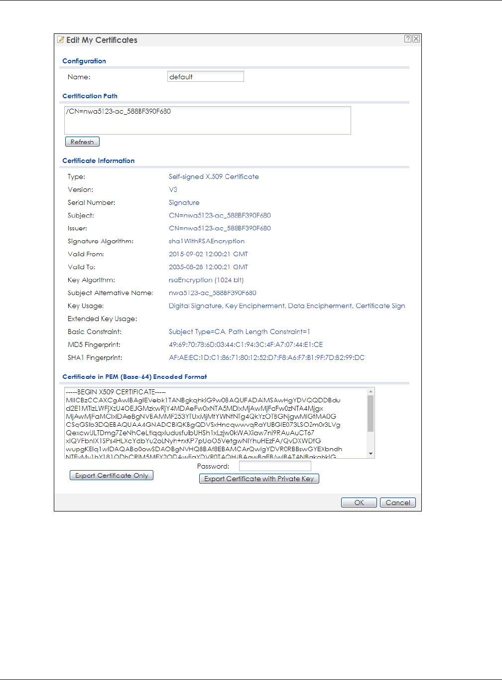
Chapter 13 Certificates
NWA / WAC Series User’s Guide
139
Figure 86 Configuration > Object > Certificate > My Certificates > Edit

Chapter 13 Certificates
NWA / WAC Series User’s Guide
140
The following table describes the labels in this screen.
Table 65 Configuration > Object > Certificate > My Certificates > Edit
LABEL DESCRIPTION
Name This field displays the identifying name of this certificate. You can use up to 31 alphanumeric
and ;‘~!@#$%^&()_+[]{}’,.=- characters.
Certification Path This field displays for a certificate, not a certification request.
Click the Refresh button to have this read-only text box display the hierarchy of certification
authorities that validate the certificate (and the certificate itself).
If the issuing certification authority is one that you have imported as a trusted certification
authority, it may be the only certification authority in the list (along with the certificate itself).
If the certificate is a self-signed certificate, the certificate itself is the only one in the list. The
NWA/WAC does not trust the certificate and displays “Not trusted” in this field if any
certificate on the path has expired or been revoked.
Refresh Click Refresh to display the certification path.
Certificate
Information
These read-only fields display detailed information about the certificate.
Type This field displays general information about the certificate. CA-signed means that a
Certification Authority signed the certificate. Self-signed means that the certificate’s owner
signed the certificate (not a certification authority). “X.509” means that this certificate was
created and signed according to the ITU-T X.509 recommendation that defines the formats
for public-key certificates.
Version This field displays the X.509 version number. “
Serial Number This field displays the certificate’s identification number given by the certification authority
or generated by the NWA/WAC.
Subject This field displays information that identifies the owner of the certificate, such as Common
Name (CN), Organizational Unit (OU), Organization (O), State (ST), and Country (C).
Issuer This field displays identifying information about the certificate’s issuing certification authority,
such as Common Name, Organizational Unit, Organization and Country.
With self-signed certificates, this is the same as the Subject Name field.
“none” displays for a certification request.
Signature Algorithm This field displays the type of algorithm that was used to sign the certificate.
Valid From This field displays the date that the certificate becomes applicable. “none” displays for a
certification request.
Valid To This field displays the date that the certificate expires. The text displays in red and includes
an Expired! message if the certificate has expired. “none” displays for a certification
request.
Key Algorithm This field displays the type of algorithm that was used to generate the certificate’s key pair
(the NWA/WAC uses RSA encryption) and the length of the key set in bits (1024 bits for
example).
Subject Alternative
Name
This field displays the certificate owner‘s IP address (IP), domain name (DNS) or e-mail
address (EMAIL).
Key Usage This field displays for what functions the certificate’s key can be used. For example,
“DigitalSignature” means that the key can be used to sign certificates and
“KeyEncipherment” means that the key can be used to encrypt text.
Extended Key Usage This field displays for what EKU (Extended Key Usage) functions the certificate’s key can be
used.
Basic Constraint This field displays general information about the certificate. For example, Subject Type=CA
means that this is a certification authority’s certificate and “Path Length Constraint=1”
means that there can only be one certification authority in the certificate’s path. This field
does not display for a certification request.

Chapter 13 Certificates
NWA / WAC Series User’s Guide
141
13.2.3 Import Certificates
Click Configuration > Object > Certificate > My Certificates > Import to open the My Certificate Import
screen. Follow the instructions in this screen to save an existing certificate to the NWA/WAC.
Note: You can import a certificate that matches a corresponding certification request that
was generated by the NWA/WAC. You can also import a certificate in PKCS#12 format,
including the certificate’s public and private keys.
The certificate you import replaces the corresponding request in the My Certificates screen.
You must remove any spaces in the certificate’s filename before you can import it.
MD5 Fingerprint This is the certificate’s message digest that the NWA/WAC calculated using the MD5
algorithm.
SHA1 Fingerprint This is the certificate’s message digest that the NWA/WAC calculated using the SHA1
algorithm.
Certificate in PEM
(Base-64) Encoded
Format
This read-only text box displays the certificate or certification request in Privacy Enhanced
Mail (PEM) format. PEM uses lowercase letters, uppercase letters and numerals to convert a
binary certificate into a printable form.
You can copy and paste a certification request into a certification authority’s web page,
an e-mail that you send to the certification authority or a text editor and save the file on a
management computer for later manual enrollment.
You can copy and paste a certificate into an e-mail to send to friends or colleagues or you
can copy and paste a certificate into a text editor and save the file on a management
computer for later distribution (via floppy disk for example).
Export Certificate
Only
Use this button to save a copy of the certificate without its private key. Click this button and
then Save in the File Download screen. The Save As screen opens, browse to the location
that you want to use and click Save.
Password If you want to export the certificate with its private key, create a password and type it here.
Make sure you keep this password in a safe place. You will need to use it if you import the
certificate to another device.
Export Certificate
with Private Key
Use this button to save a copy of the certificate with its private key. Type the certificate’s
password and click this button. Click Save in the File Download screen. The Save As screen
opens, browse to the location that you want to use and click Save.
OK Click OK to save your changes back to the NWA/WAC. You can only change the name.
Cancel Click Cancel to quit and return to the My Certificates screen.
Table 65 Configuration > Object > Certificate > My Certificates > Edit
LABEL DESCRIPTION
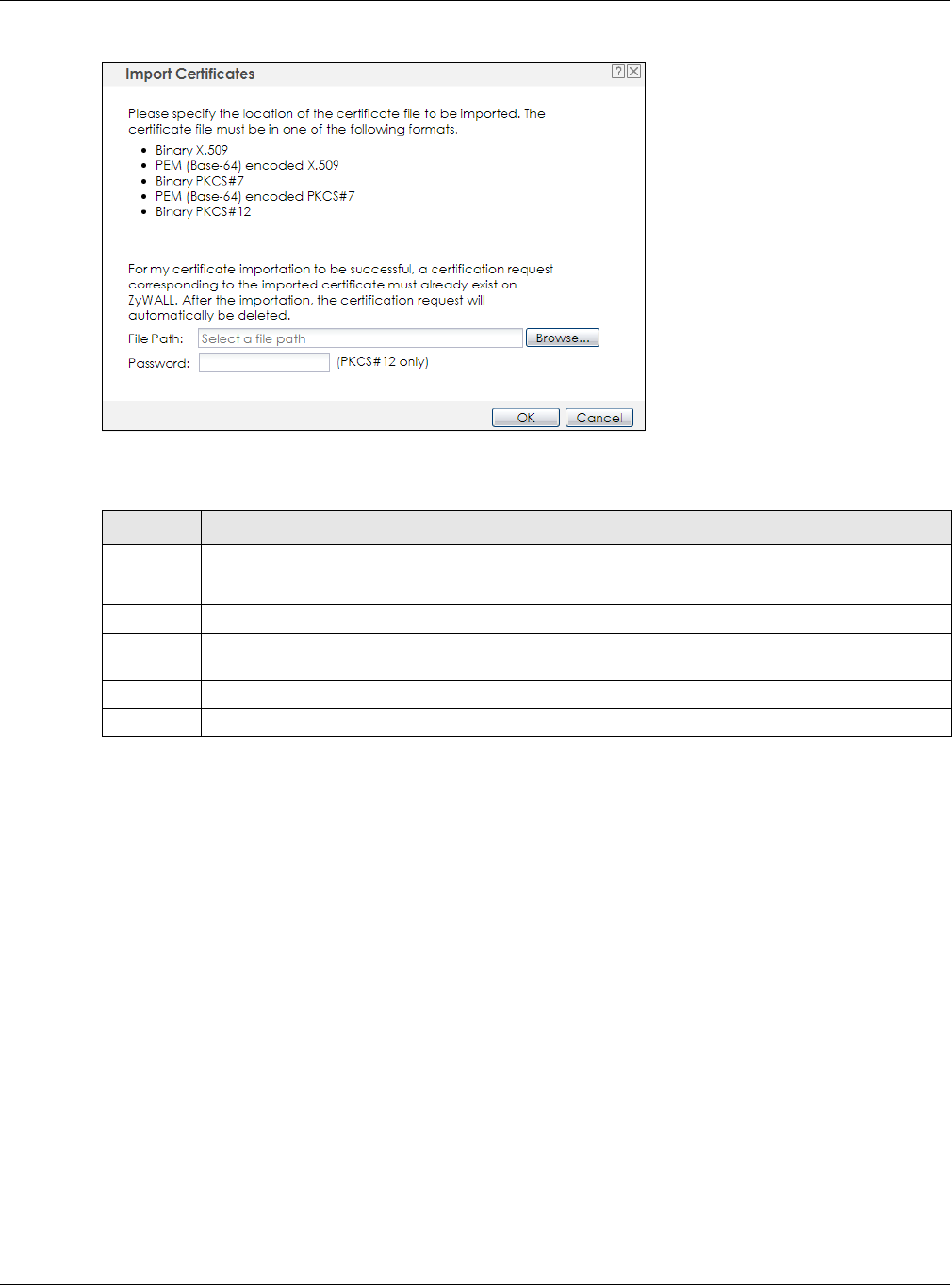
Chapter 13 Certificates
NWA / WAC Series User’s Guide
142
Figure 87 Configuration > Object > Certificate > My Certificates > Import
The following table describes the labels in this screen.
13.3 Trusted Certificates
Click Configuration > Object > Certificate > Trusted Certificates to open the Trusted Certificates screen.
This screen displays a summary list of certificates that you have set the NWA/WAC to accept as trusted.
The NWA/WAC also accepts any valid certificate signed by a certificate on this list as being trustworthy;
thus you do not need to import any certificate that is signed by one of these certificates.
Table 66 Configuration > Object > Certificate > My Certificates > Import
LABEL DESCRIPTION
File Path Type in the location of the file you want to upload in this field or click Browse to find it.
You cannot import a certificate with the same name as a certificate that is already in the NWA/WAC.
Browse Click Browse to find the certificate file you want to upload.
Password This field only applies when you import a binary PKCS#12 format file. Type the file’s password that was
created when the PKCS #12 file was exported.
OK Click OK to save the certificate on the NWA/WAC.
Cancel Click Cancel to quit and return to the My Certificates screen.
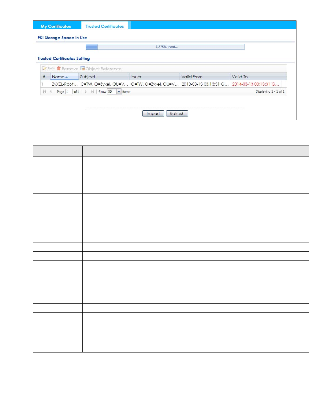
Chapter 13 Certificates
NWA / WAC Series User’s Guide
143
Figure 88 Configuration > Object > Certificate > Trusted Certificates
The following table describes the labels in this screen.
13.3.1 Edit Trusted Certificates
Click Configuration > Object > Certificate > Trusted Certificates and then a certificate’s Edit icon to open
the Trusted Certificates Edit screen. Use this screen to view in-depth information about the certificate,
change the certificate’s name and set whether or not you want the NWA/WAC to check a certification
authority’s list of revoked certificates before trusting a certificate issued by the certification authority.
Table 67 Configuration > Object > Certificate > Trusted Certificates
LABEL DESCRIPTION
PKI Storage Space
in Use
This bar displays the percentage of the NWA/WAC’s PKI storage space that is currently in use.
When the storage space is almost full, you should consider deleting expired or unnecessary
certificates before adding more certificates.
Edit Double-click an entry or select it and click Edit to open a screen with an in-depth list of
information about the certificate.
Remove The NWA/WAC keeps all of your certificates unless you specifically delete them. Uploading a
new firmware or default configuration file does not delete your certificates. To remove an
entry, select it and click Remove. The NWA/WAC confirms you want to remove it before doing
so. Subsequent certificates move up by one when you take this action.
Object Reference You cannot delete certificates that any of the NWA/WAC’s features are configured to use.
Select an entry and click Object Reference to open a screen that shows which settings use the
entry.
# This field displays the certificate index number. The certificates are listed in alphabetical order.
Name This field displays the name used to identify this certificate.
Subject This field displays identifying information about the certificate’s owner, such as CN (Common
Name), OU (Organizational Unit or department), O (Organization or company) and C
(Country). It is recommended that each certificate have unique subject information.
Issuer This field displays identifying information about the certificate’s issuing certification authority,
such as a common name, organizational unit or department, organization or company and
country. With self-signed certificates, this is the same information as in the Subject field.
Valid From This field displays the date that the certificate becomes applicable.
Valid To This field displays the date that the certificate expires. The text displays in red and includes an
Expired! message if the certificate has expired.
Import Click Import to open a screen where you can save the certificate of a certification authority
that you trust, from your computer to the NWA/WAC.
Refresh Click this button to display the current validity status of the certificates.
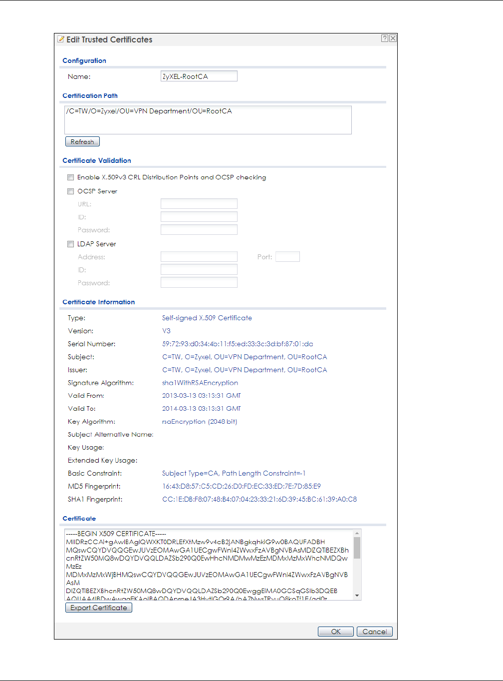
Chapter 13 Certificates
NWA / WAC Series User’s Guide
144
Figure 89 Configuration > Object > Certificate > Trusted Certificates > Edit

Chapter 13 Certificates
NWA / WAC Series User’s Guide
145
The following table describes the labels in this screen.
Table 68 Configuration > Object > Certificate > Trusted Certificates > Edit
LABEL DESCRIPTION
Name This field displays the identifying name of this certificate. You can change the name. You
can use up to 31 alphanumeric and ;‘~!@#$%^&()_+[]{}’,.=- characters.
Certification Path Click the Refresh button to have this read-only text box display the end entity’s certificate
and a list of certification authority certificates that shows the hierarchy of certification
authorities that validate the end entity’s certificate. If the issuing certification authority is one
that you have imported as a trusted certificate, it may be the only certification authority in
the list (along with the end entity’s own certificate). The NWA/WAC does not trust the end
entity’s certificate and displays “Not trusted” in this field if any certificate on the path has
expired or been revoked.
Refresh Click Refresh to display the certification path.
Enable X.509v3 CRL
Distribution Points
and OCSP checking
Select this check box to have the NWA/WAC check incoming certificates that are signed
by this certificate against a Certificate Revocation List (CRL) or an OCSP server. You also
need to configure the OSCP or LDAP server details.
OCSP Server Select this check box if the directory server uses OCSP (Online Certificate Status Protocol).
URL Type the protocol, IP address and pathname of the OCSP server.
ID The NWA/WAC may need to authenticate itself in order to assess the OCSP server. Type the
login name (up to 31 ASCII characters) from the entity maintaining the server (usually a
certification authority).
Password Type the password (up to 31 ASCII characters) from the entity maintaining the OCSP server
(usually a certification authority).
LDAP Server Select this check box if the directory server uses LDAP (Lightweight Directory Access
Protocol). LDAP is a protocol over TCP that specifies how clients access directories of
certificates and lists of revoked certificates.
Address Type the IP address (in dotted decimal notation) of the directory server.
Port Use this field to specify the LDAP server port number. You must use the same server port
number that the directory server uses. 389 is the default server port number for LDAP.
ID The NWA/WAC may need to authenticate itself in order to assess the CRL directory server.
Type the login name (up to 31 ASCII characters) from the entity maintaining the server
(usually a certification authority).
Password Type the password (up to 31 ASCII characters) from the entity maintaining the CRL directory
server (usually a certification authority).
Certificate
Information
These read-only fields display detailed information about the certificate.
Type This field displays general information about the certificate. CA-signed means that a
Certification Authority signed the certificate. Self-signed means that the certificate’s owner
signed the certificate (not a certification authority). X.509 means that this certificate was
created and signed according to the ITU-T X.509 recommendation that defines the formats
for public-key certificates.
Version This field displays the X.509 version number.
Serial Number This field displays the certificate’s identification number given by the certification authority.
Subject This field displays information that identifies the owner of the certificate, such as Common
Name (CN), Organizational Unit (OU), Organization (O) and Country (C).
Issuer This field displays identifying information about the certificate’s issuing certification authority,
such as Common Name, Organizational Unit, Organization and Country.
With self-signed certificates, this is the same information as in the Subject Name field.
Signature Algorithm This field displays the type of algorithm that was used to sign the certificate. Some
certification authorities use rsa-pkcs1-sha1 (RSA public-private key encryption algorithm and
the SHA1 hash algorithm). Other certification authorities may use rsa-pkcs1-md5 (RSA
public-private key encryption algorithm and the MD5 hash algorithm).

Chapter 13 Certificates
NWA / WAC Series User’s Guide
146
13.3.2 Import Trusted Certificates
Click Configuration > Object > Certificate > Trusted Certificates > Import to open the Import Trusted
Certificates screen. Follow the instructions in this screen to save a trusted certificate to the NWA/WAC.
Note: You must remove any spaces from the certificate’s filename before you can import the
certificate.
Valid From This field displays the date that the certificate becomes applicable. The text displays in red
and includes a Not Yet Valid! message if the certificate has not yet become applicable.
Valid To This field displays the date that the certificate expires. The text displays in red and includes
an Expiring! or Expired! message if the certificate is about to expire or has already expired.
Key Algorithm This field displays the type of algorithm that was used to generate the certificate’s key pair
(the NWA/WAC uses RSA encryption) and the length of the key set in bits (1024 bits for
example).
Subject Alternative
Name
This field displays the certificate’s owner‘s IP address (IP), domain name (DNS) or e-mail
address (EMAIL).
Key Usage This field displays for what functions the certificate’s key can be used. For example,
“DigitalSignature” means that the key can be used to sign certificates and
“KeyEncipherment” means that the key can be used to encrypt text.
Basic Constraint This field displays general information about the certificate. For example, Subject Type=CA
means that this is a certification authority’s certificate and “Path Length Constraint=1”
means that there can only be one certification authority in the certificate’s path.
MD5 Fingerprint This is the certificate’s message digest that the NWA/WAC calculated using the MD5
algorithm. You can use this value to verify with the certification authority (over the phone for
example) that this is actually their certificate.
SHA1 Fingerprint This is the certificate’s message digest that the NWA/WAC calculated using the SHA1
algorithm. You can use this value to verify with the certification authority (over the phone for
example) that this is actually their certificate.
Certificate This read-only text box displays the certificate or certification request in Privacy Enhanced
Mail (PEM) format. PEM uses lowercase letters, uppercase letters and numerals to convert a
binary certificate into a printable form.
You can copy and paste the certificate into an e-mail to send to friends or colleagues or
you can copy and paste the certificate into a text editor and save the file on a
management computer for later distribution (via floppy disk for example).
Export Certificate Click this button and then Save in the File Download screen. The Save As screen opens,
browse to the location that you want to use and click Save.
OK Click OK to save your changes back to the NWA/WAC. You can only change the name.
Cancel Click Cancel to quit and return to the Trusted Certificates screen.
Table 68 Configuration > Object > Certificate > Trusted Certificates > Edit (continued)
LABEL DESCRIPTION
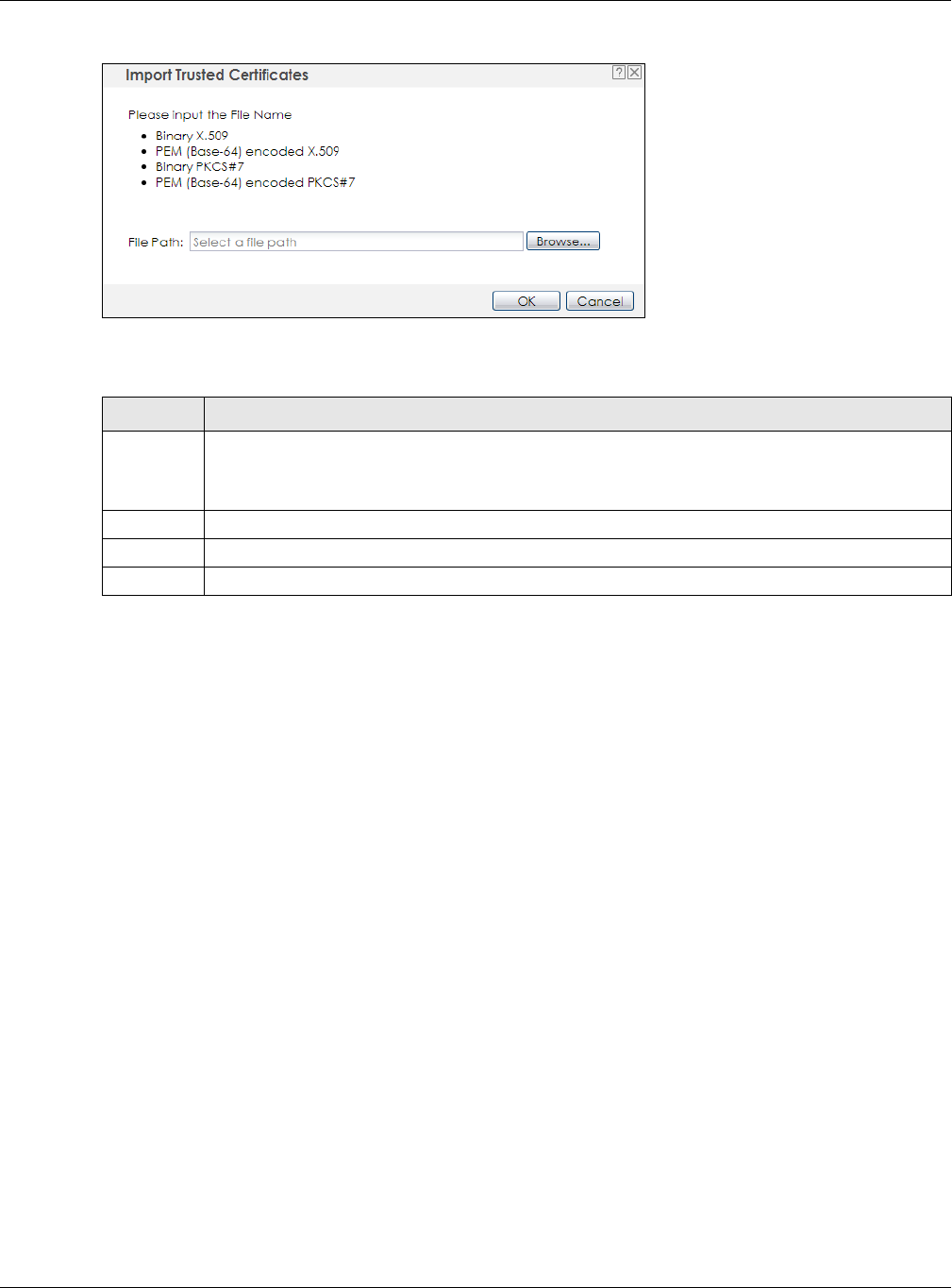
Chapter 13 Certificates
NWA / WAC Series User’s Guide
147
Figure 90 Configuration > Object > Certificate > Trusted Certificates > Import
The following table describes the labels in this screen.
13.4 Technical Reference
The following section contains additional technical information about the features described in this
chapter.
OCSP
OCSP (Online Certificate Status Protocol) allows an application or device to check whether a certificate
is valid. With OCSP the NWA/WAC checks the status of individual certificates instead of downloading a
Certificate Revocation List (CRL). OCSP has two main advantages over a CRL. The first is real-time status
information. The second is a reduction in network traffic since the NWA/WAC only gets information on
the certificates that it needs to verify, not a huge list. When the NWA/WAC requests certificate status
information, the OCSP server returns a “expired”, “current” or “unknown” response.
Table 69 Configuration > Object > Certificate > Trusted Certificates > Import
LABEL DESCRIPTION
File Path Type in the location of the file you want to upload in this field or click Browse to find it.
You cannot import a certificate with the same name as a certificate that is already in the NWA/
WAC.
Browse Click Browse to find the certificate file you want to upload.
OK Click OK to save the certificate on the NWA/WAC.
Cancel Click Cancel to quit and return to the previous screen.
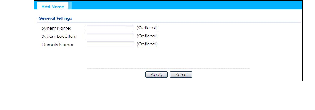
NWA / WAC Series User’s Guide
148
CHAPTER 14
System
14.1 Overview
Use the system screens to configure general NWA/WAC settings.
14.1.1 What You Can Do in this Chapter
•The Host Name screen (Section 14.2 on page 148) configures a unique name for the NWA/WAC in
your network.
• The Date/Time screen (Section 14.3 on page 149) configures the date and time for the NWA/WAC.
• The WWW screens (Section 14.4 on page 153) configure settings for HTTP or HTTPS access to the NWA/
WAC.
• The SSH screen (Section 14.5 on page 163) configures SSH (Secure SHell) for securely accessing the
NWA/WAC’s command line interface.
• The Telnet screen (Section 14.6 on page 167) configures Telnet for accessing the NWA/WAC’s
command line interface.
•The FTP screen (Section 14.7 on page 167) specifies FTP server settings. You can upload and
download the NWA/WAC’s firmware and configuration files using FTP. Please also see Chapter 16 on
page 185 for more information about firmware and configuration files.
• The SNMP screens (Section 14.8 on page 168) configure the device’s SNMP settings, including profiles
that define allowed SNMPv3 access.
14.2 Host Name
A host name is the unique name by which a device is known on a network. Click Configuration > System
> Host Name to open this screen.
Figure 91 Configuration > System > Host Name

Chapter 14 System
NWA / WAC Series User’s Guide
149
The following table describes the labels in this screen.
14.3 Date and Time
For effective scheduling and logging, the NWA/WAC system time must be accurate. The NWA/WAC has
a software mechanism to set the time manually or get the current time and date from an external
server.
To change your NWA/WAC’s time based on your local time zone and date, click Configuration > System
> Date/Time. The screen displays as shown. You can manually set the NWA/WAC’s time and date or
have the NWA/WAC get the date and time from a time server.
Table 70 Configuration > System > Host Name
LABEL DESCRIPTION
System Name Choose a descriptive name to identify your NWA/WAC device. This name can be up to 64
alphanumeric characters long. Spaces are not allowed, but dashes (-) underscores (_) and
periods (.) are accepted.
System Location Specify the name of the place where the NWA/WAC is located. You can enter up to 60
alphanumeric and '()’ ,:;?! +-*/= #$%@ characters. Spaces and underscores are allowed. The
name should start with a letter.
Domain Name Enter the domain name (if you know it) here. This name is propagated to DHCP clients
connected to interfaces with the DHCP server enabled. This name can be up to 254
alphanumeric characters long. Spaces are not allowed, but dashes “-” are accepted.
Apply Click Apply to save your changes back to the NWA/WAC.
Reset Click Reset to return the screen to its last-saved settings.
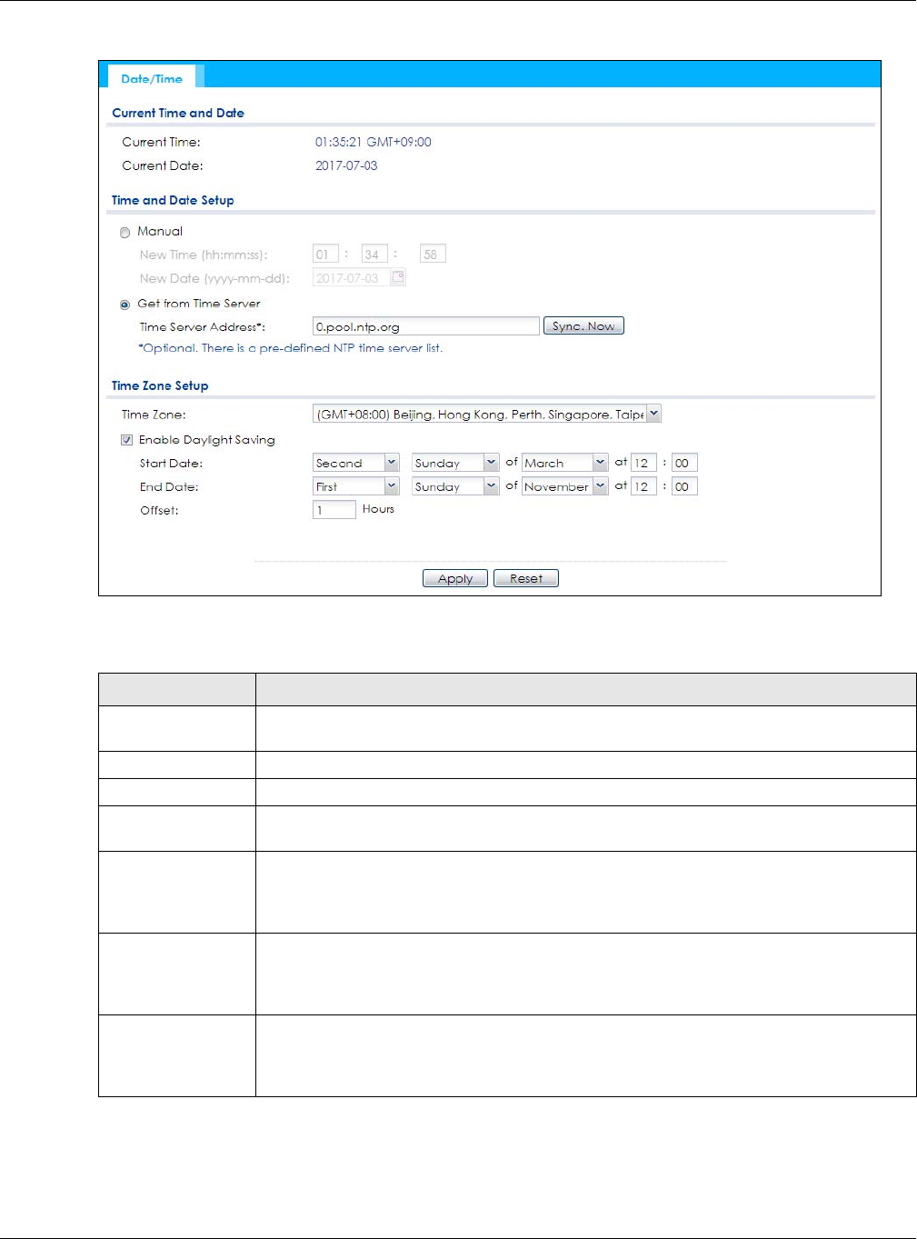
Chapter 14 System
NWA / WAC Series User’s Guide
150
Figure 92 Configuration > System > Date/Time
The following table describes the labels in this screen.
Table 71 Configuration > System > Date/Time
LABEL DESCRIPTION
Current Time and
Date
Current Time This field displays the present time of your NWA/WAC.
Current Date This field displays the present date of your NWA/WAC.
Time and Date
Setup
Manual Select this radio button to enter the time and date manually. If you configure a new time
and date, time zone and daylight saving at the same time, the time zone and daylight
saving will affect the new time and date you entered. When you enter the time settings
manually, the NWA/WAC uses the new setting once you click Apply.
New Time
(hh:mm:ss)
This field displays the last updated time from the time server or the last time configured
manually.
When you set Time and Date Setup to Manual, enter the new time in this field and then click
Apply.
New Date
(yyyy-mm-dd)
This field displays the last updated date from the time server or the last date configured
manually.
When you set Time and Date Setup to Manual, enter the new date in this field and then click
Apply.

Chapter 14 System
NWA / WAC Series User’s Guide
151
Get from Time
Server
Select this radio button to have the NWA/WAC get the time and date from the time server
you specify below. The NWA/WAC requests time and date settings from the time server
under the following circumstances.
• When the NWA/WAC starts up.
• When you click Apply or Sync. Now in this screen.
• 24-hour intervals after starting up.
Time Server Address Enter the IP address or URL of your time server. Check with your ISP/network administrator if
you are unsure of this information.
Sync. Now Click this button to have the NWA/WAC get the time and date from a time server (see the
Time Server Address field). This also saves your changes (except the daylight saving settings).
Time Zone Setup
Time Zone Choose the time zone of your location. This will set the time difference between your time
zone and Greenwich Mean Time (GMT).
Enable Daylight
Saving
Daylight saving is a period from late spring to fall when many countries set their clocks
ahead of normal local time by one hour to give more daytime light in the evening.
Select this option if you use Daylight Saving Time.
Start Date Configure the day and time when Daylight Saving Time starts if you selected Enable Daylight
Saving. The at field uses the 24 hour format. Here are a couple of examples:
Daylight Saving Time starts in most parts of the United States on the second Sunday of
March. Each time zone in the United States starts using Daylight Saving Time at 2 A.M. local
time. So in the United States you would select Second, Sunday, March and type 2 in the at
field.
Daylight Saving Time starts in the European Union on the last Sunday of March. All of the time
zones in the European Union start using Daylight Saving Time at the same moment (1 A.M.
GMT or UTC). So in the European Union you would select Last, Sunday, March. The time you
type in the at field depends on your time zone. In Germany for instance, you would type 2
because Germany's time zone is one hour ahead of GMT or UTC (GMT+1).
End Date Configure the day and time when Daylight Saving Time ends if you selected Enable Daylight
Saving. The at field uses the 24 hour format. Here are a couple of examples:
Daylight Saving Time ends in the United States on the first Sunday of November. Each time
zone in the United States stops using Daylight Saving Time at 2 A.M. local time. So in the
United States you would select First, Sunday, November and type 2 in the at field.
Daylight Saving Time ends in the European Union on the last Sunday of October. All of the
time zones in the European Union stop using Daylight Saving Time at the same moment (1
A.M. GMT or UTC). So in the European Union you would select Last, Sunday, October. The
time you type in the at field depends on your time zone. In Germany for instance, you would
type 2 because Germany's time zone is one hour ahead of GMT or UTC (GMT+1).
Offset Specify how much the clock changes when daylight saving begins and ends.
Enter a number from 1 to 5.5 (by 0.5 increments).
For example, if you set this field to 3.5, a log occurred at 6 P.M. in local official time will
appear as if it had occurred at 10:30 P.M.
Apply Click Apply to save your changes back to the NWA/WAC.
Reset Click Reset to return the screen to its last-saved settings.
Table 71 Configuration > System > Date/Time (continued)
LABEL DESCRIPTION
Chapter 14 System
NWA / WAC Series User’s Guide
152
14.3.1 Pre-defined NTP Time Servers List
When you turn on the NWA/WAC for the first time, the date and time start at 2003-01-01 00:00:00. The
NWA/WAC then attempts to synchronize with one of the following pre-defined list of Network Time
Protocol (NTP) time servers.
The NWA/WAC continues to use the following pre-defined list of NTP time servers if you do not specify a
time server or it cannot synchronize with the time server you specified.
When the NWA/WAC uses the pre-defined list of NTP time servers, it randomly selects one server and tries
to synchronize with it. If the synchronization fails, then the NWA/WAC goes through the rest of the list in
order from the first one tried until either it is successful or all the pre-defined NTP time servers have been
tried.
14.3.2 Time Server Synchronization
Click the Sync. Now button to get the time and date from the time server you specified in the Time
Server Address field.
When the Loading message appears, you may have to wait up to one minute.
Figure 93 Loading
The Current Time and Current Date fields will display the appropriate settings if the synchronization is
successful.
If the synchronization was not successful, a log displays in the View Log screen. Try re-configuring the
Date/Time screen.
To manually set the NWA/WAC date and time:
1Click System > Date/Time.
2Select Manual under Time and Date Setup.
3Enter the NWA/WAC’s time in the New Time field.
4Enter the NWA/WAC’s date in the New Date field.
5Under Time Zone Setup, select your Time Zone from the list.
6As an option you can select the Enable Daylight Saving check box to adjust the NWA/WAC clock for
daylight savings.
7Click Apply.
Table 72 Default Time Servers
0.pool.ntp.org
1.pool.ntp.org
2.pool.ntp.org
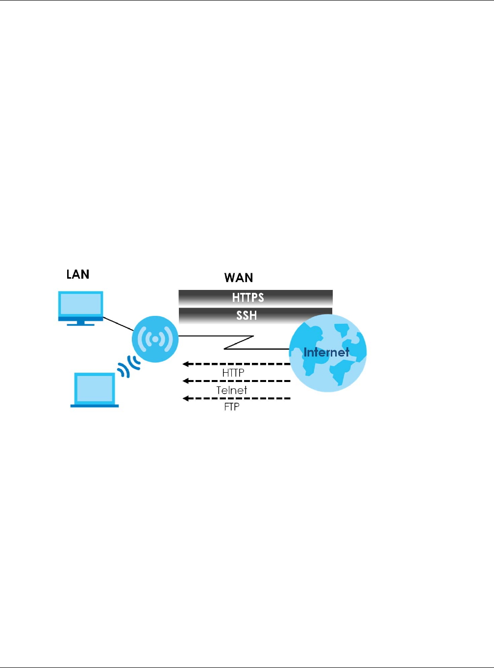
Chapter 14 System
NWA / WAC Series User’s Guide
153
To get the NWA/WAC date and time from a time server:
1Click System > Date/Time.
2Select Get from Time Server under Time and Date Setup.
3Under Time Zone Setup, select your Time Zone from the list.
4Under Time and Date Setup, enter a Time Server Address.
5Click Apply.
14.4 WWW Overview
The following figure shows secure and insecure management of the NWA/WAC coming in from the
WAN. HTTPS and SSH access are secure. HTTP, Telnet, and FTP management access are not secure.
Figure 94 Secure and Insecure Service Access From the WAN
14.4.1 Service Access Limitations
A service cannot be used to access the NWA/WAC when you have disabled that service in the
corresponding screen.
14.4.2 System Timeout
There is a lease timeout for administrators. The NWA/WAC automatically logs you out if the
management session remains idle for longer than this timeout period. The management session does
not time out when a statistics screen is polling.
Each user is also forced to log in the NWA/WAC for authentication again when the reauthentication
time expires.
You can change the timeout settings in the User screens.
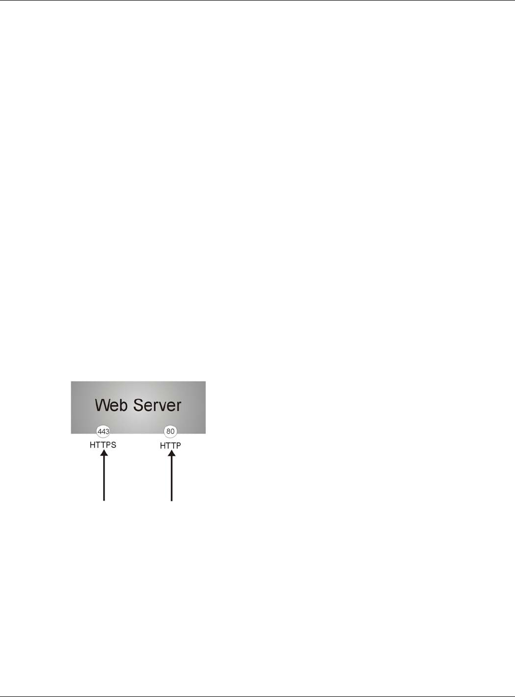
Chapter 14 System
NWA / WAC Series User’s Guide
154
14.4.3 HTTPS
You can set the NWA/WAC to use HTTP or HTTPS (HTTPS adds security) for Web Configurator sessions.
HTTPS (HyperText Transfer Protocol over Secure Socket Layer, or HTTP over SSL) is a web protocol that
encrypts and decrypts web pages. Secure Socket Layer (SSL) is an application-level protocol that
enables secure transactions of data by ensuring confidentiality (an unauthorized party cannot read the
transferred data), authentication (one party can identify the other party) and data integrity (you know if
data has been changed).
It relies upon certificates, public keys, and private keys (see Chapter 13 on page 132 for more
information).
HTTPS on the NWA/WAC is used so that you can securely access the NWA/WAC using the Web
Configurator. The SSL protocol specifies that the HTTPS server (the NWA/WAC) must always authenticate
itself to the HTTPS client (the computer which requests the HTTPS connection with the NWA/WAC),
whereas the HTTPS client only should authenticate itself when the HTTPS server requires it to do so (select
Authenticate Client Certificates in the WWW screen). Authenticate Client Certificates is optional and if
selected means the HTTPS client must send the NWA/WAC a certificate. You must apply for a certificate
for the browser from a CA that is a trusted CA on the NWA/WAC.
Please refer to the following figure.
1HTTPS connection requests from an SSL-aware web browser go to port 443 (by default) on the NWA/
WAC’s web server.
2HTTP connection requests from a web browser go to port 80 (by default) on the NWA/WAC’s web server.
Figure 95 HTTP/HTTPS Implementation
Note: If you disable HTTP in the WWW screen, then the NWA/WAC blocks all HTTP connection
attempts.
14.4.4 Configuring WWW Service Control
Click Configuration > System > WWW to open the WWW screen. Use this screen to specify HTTP or HTTPS
settings.
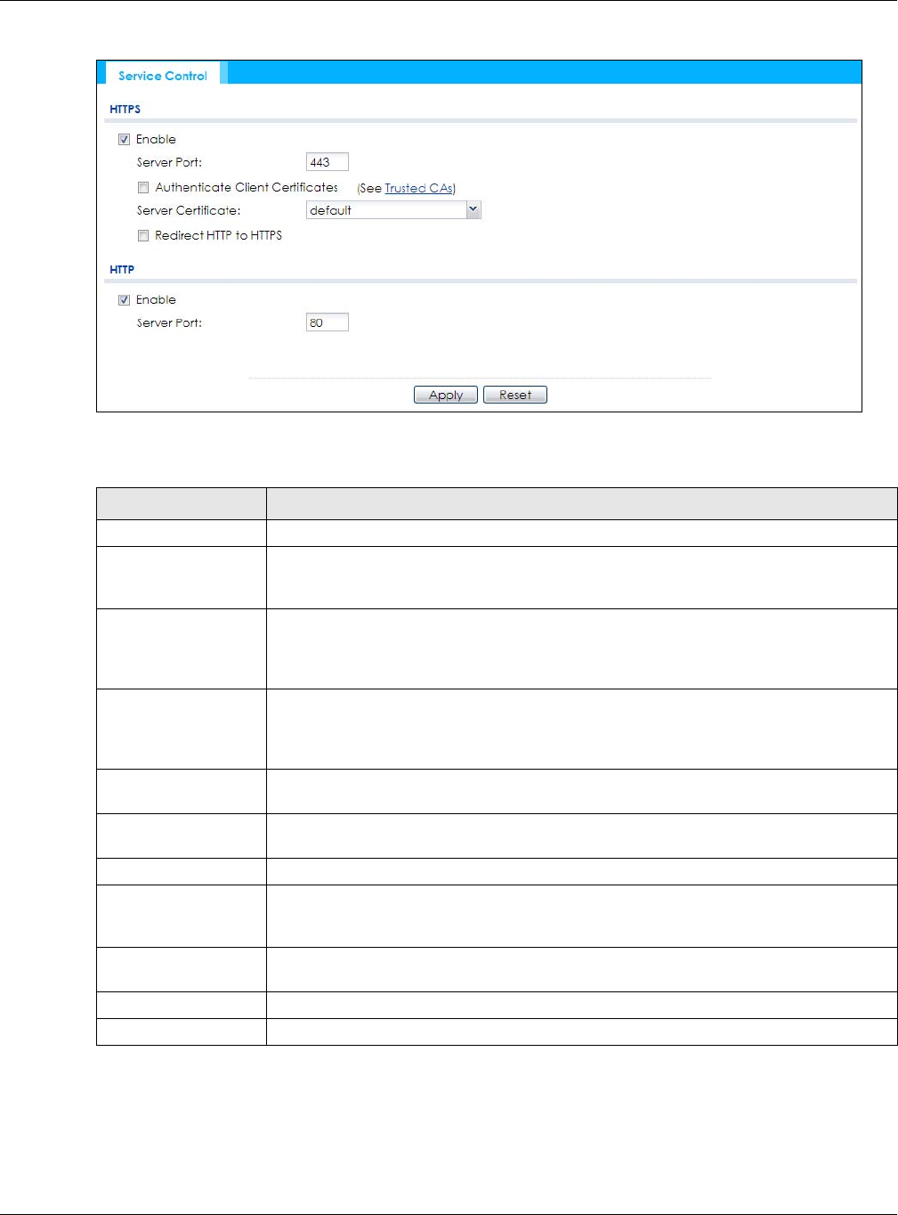
Chapter 14 System
NWA / WAC Series User’s Guide
155
Figure 96 Configuration > System > WWW > Service Control
The following table describes the labels in this screen.
14.4.5 HTTPS Example
If you haven’t changed the default HTTPS port on the NWA/WAC, then in your browser enter “https://
NWA/WAC IP Address/” as the web site address where “NWA/WAC IP Address” is the IP address or
domain name of the NWA/WAC you wish to access.
Table 73 Configuration > System > WWW > Service Control
LABEL DESCRIPTION
HTTPS
Enable Select the check box to allow or disallow the computer with the IP address that matches
the IP address(es) in the Service Control table to access the NWA/WAC Web Configurator
using secure HTTPs connections.
Server Port The HTTPS server listens on port 443 by default. If you change the HTTPS server port to a
different number on the NWA/WAC, for example 8443, then you must notify people who
need to access the NWA/WAC Web Configurator to use “https://NWA/WAC IP
Address:8443” as the URL.
Authenticate Client
Certificates
Select Authenticate Client Certificates (optional) to require the SSL client to authenticate
itself to the NWA/WAC by sending the NWA/WAC a certificate. To do that the SSL client
must have a CA-signed certificate from a CA that has been imported as a trusted CA on
the NWA/WAC.
Server Certificate Select a certificate the HTTPS server (the NWA/WAC) uses to authenticate itself to the
HTTPS client. You must have certificates already configured in the My Certificates screen.
Redirect HTTP to HTTPS To allow only secure Web Configurator access, select this to redirect all HTTP connection
requests to the HTTPS server.
HTTP
Enable Select the check box to allow or disallow the computer with the IP address that matches
the IP address(es) in the Service Control table to access the NWA/WAC Web Configurator
using HTTP connections.
Server Port You may change the server port number for a service if needed, however you must use
the same port number in order to use that service to access the NWA/WAC.
Apply Click Apply to save your changes back to the NWA/WAC.
Reset Click Reset to return the screen to its last-saved settings.
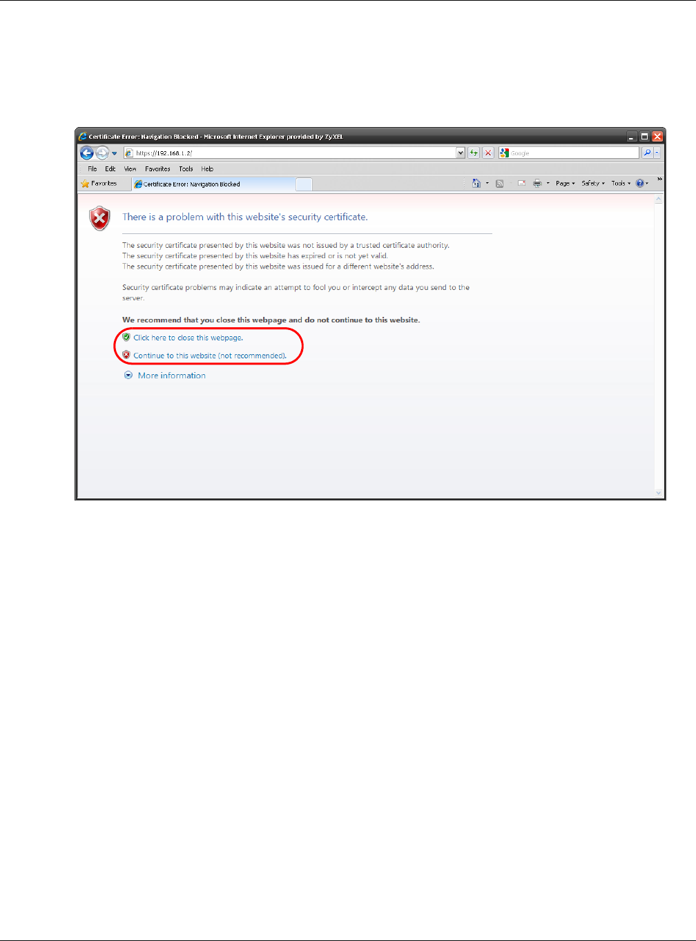
Chapter 14 System
NWA / WAC Series User’s Guide
156
14.4.5.1 Internet Explorer Warning Messages
When you attempt to access the NWA/WAC HTTPS server, you will see the error message shown in the
following screen.
Figure 97 Security Alert Dialog Box (Internet Explorer)
Select Continue to this website. to proceed to the Web Configurator login screen. Otherwise, select
Click here to close this webpage. to block the access.
14.4.5.2 Mozilla Firefox Warning Messages
When you attempt to access the NWA/WAC HTTPS server, a The Connection is Untrusted screen appears
as shown in the following screen. Click Technical Details if you want to verify more information about the
certificate from the NWA/WAC.
Select I Understand the Risks and then click Add Exception to add the NWA/WAC to the security
exception list. Click Confirm Security Exception.
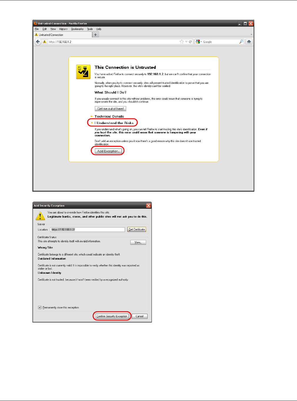
Chapter 14 System
NWA / WAC Series User’s Guide
157
Figure 98 Security Certificate 1 (Firefox)
Figure 99 Security Certificate 2 (Firefox)
14.4.5.3 Avoiding Browser Warning Messages
Here are the main reasons your browser displays warnings about the NWA/WAC’s HTTPS server
certificate and what you can do to avoid seeing the warnings:
• The issuing certificate authority of the NWA/WAC’s HTTPS server certificate is not one of the browser’s
trusted certificate authorities. The issuing certificate authority of the NWA/WAC's factory default
certificate is the NWA/WAC itself since the certificate is a self-signed certificate.
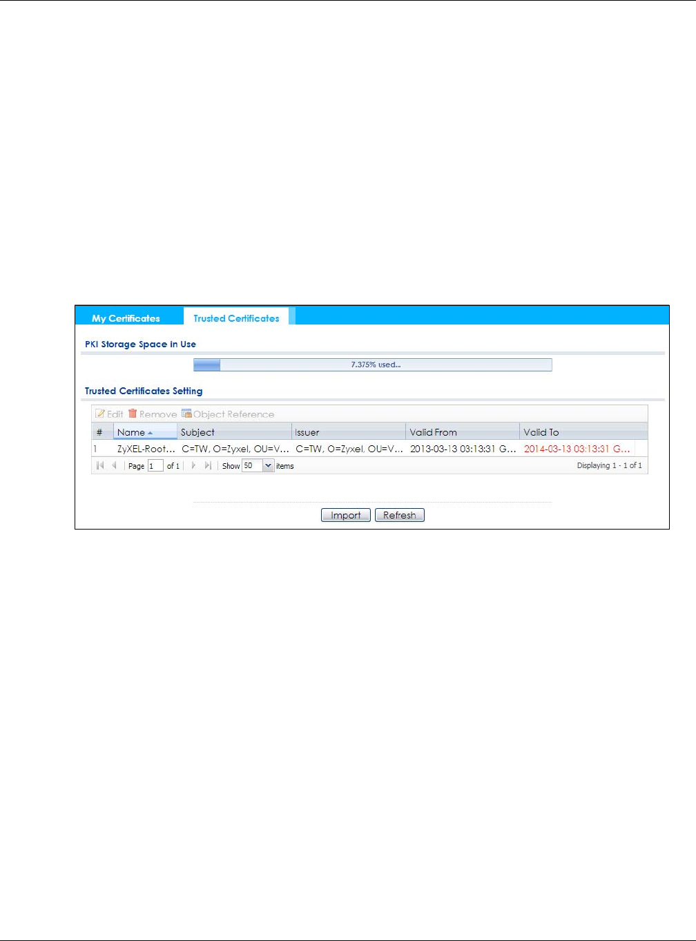
Chapter 14 System
NWA / WAC Series User’s Guide
158
• For the browser to trust a self-signed certificate, import the self-signed certificate into your operating
system as a trusted certificate.
• To have the browser trust the certificates issued by a certificate authority, import the certificate
authority’s certificate into your operating system as a trusted certificate. Refer to Appendix A on
page 214 for details.
14.4.5.4 Enrolling and Importing SSL Client Certificates
The SSL client needs a certificate if Authenticate Client Certificates is selected on the NWA/WAC.
You must have imported at least one trusted CA to the NWA/WAC in order for the Authenticate Client
Certificates to be active (see the Certificates chapter for details).
Apply for a certificate from a Certification Authority (CA) that is trusted by the NWA/WAC (see the
NWA/WAC’s Trusted Certificates Web Configurator screen).
Figure 100 Trusted Certificates
The CA sends you a package containing the CA’s trusted certificate(s), your personal certificate(s) and
a password to install the personal certificate(s).
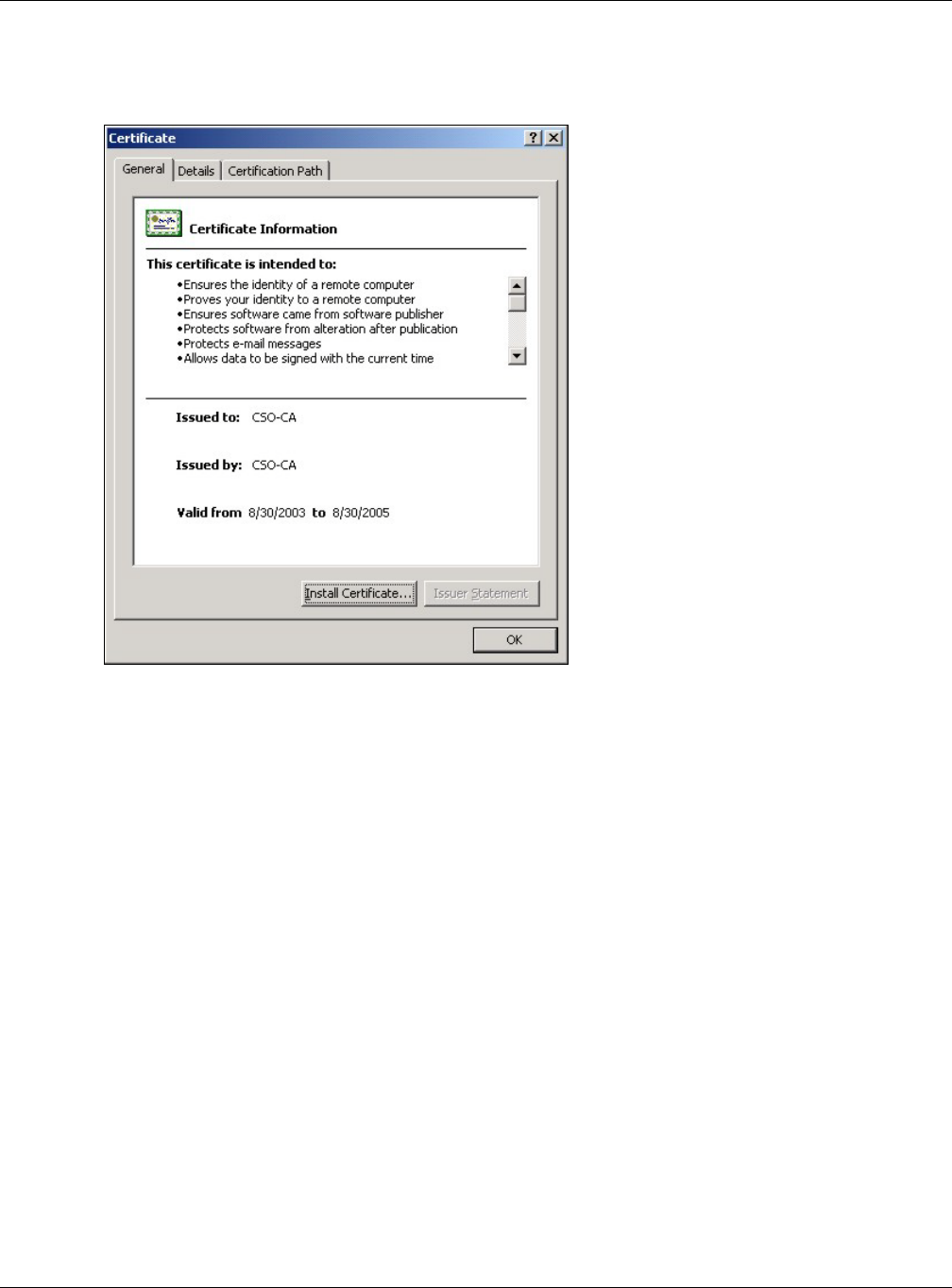
Chapter 14 System
NWA / WAC Series User’s Guide
159
14.4.5.5 Installing the CA’s Certificate
1Double click the CA’s trusted certificate to produce a screen similar to the one shown next.
2Click Install Certificate and follow the wizard as shown.
14.4.5.6 Installing a Personal Certificate
You need a password in advance. The CA may issue the password or you may have to specify it during
the enrollment. Double-click the personal certificate given to you by the CA to produce a screen similar
to the one shown next.
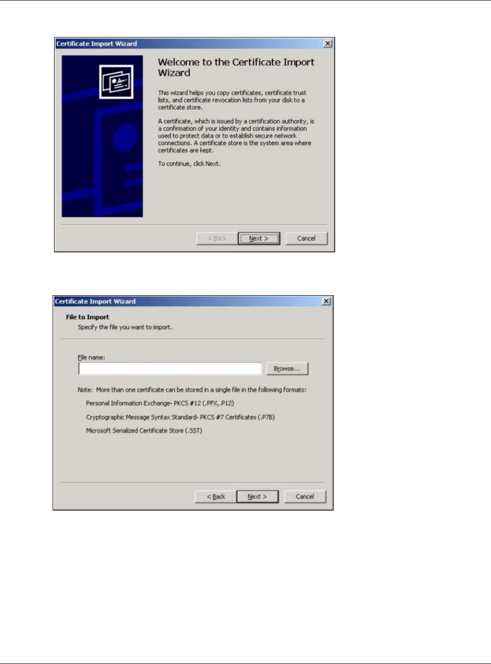
Chapter 14 System
NWA / WAC Series User’s Guide
160
1Click Next to begin the wizard.
2The file name and path of the certificate you double-clicked should automatically appear in the File
name text box. Click Browse if you wish to import a different certificate.
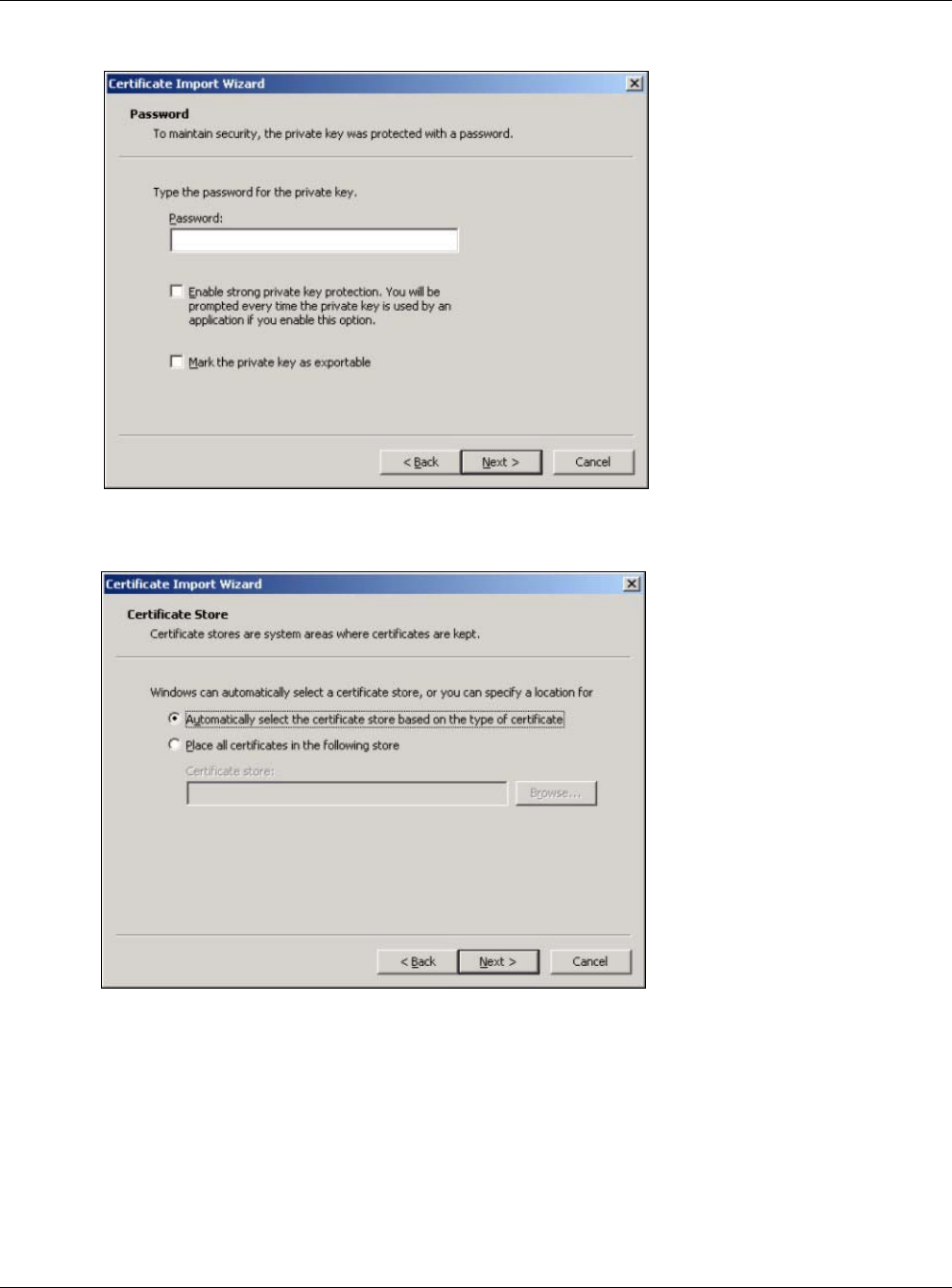
Chapter 14 System
NWA / WAC Series User’s Guide
161
3Enter the password given to you by the CA.
4Have the wizard determine where the certificate should be saved on your computer or select Place all
certificates in the following store and choose a different location.
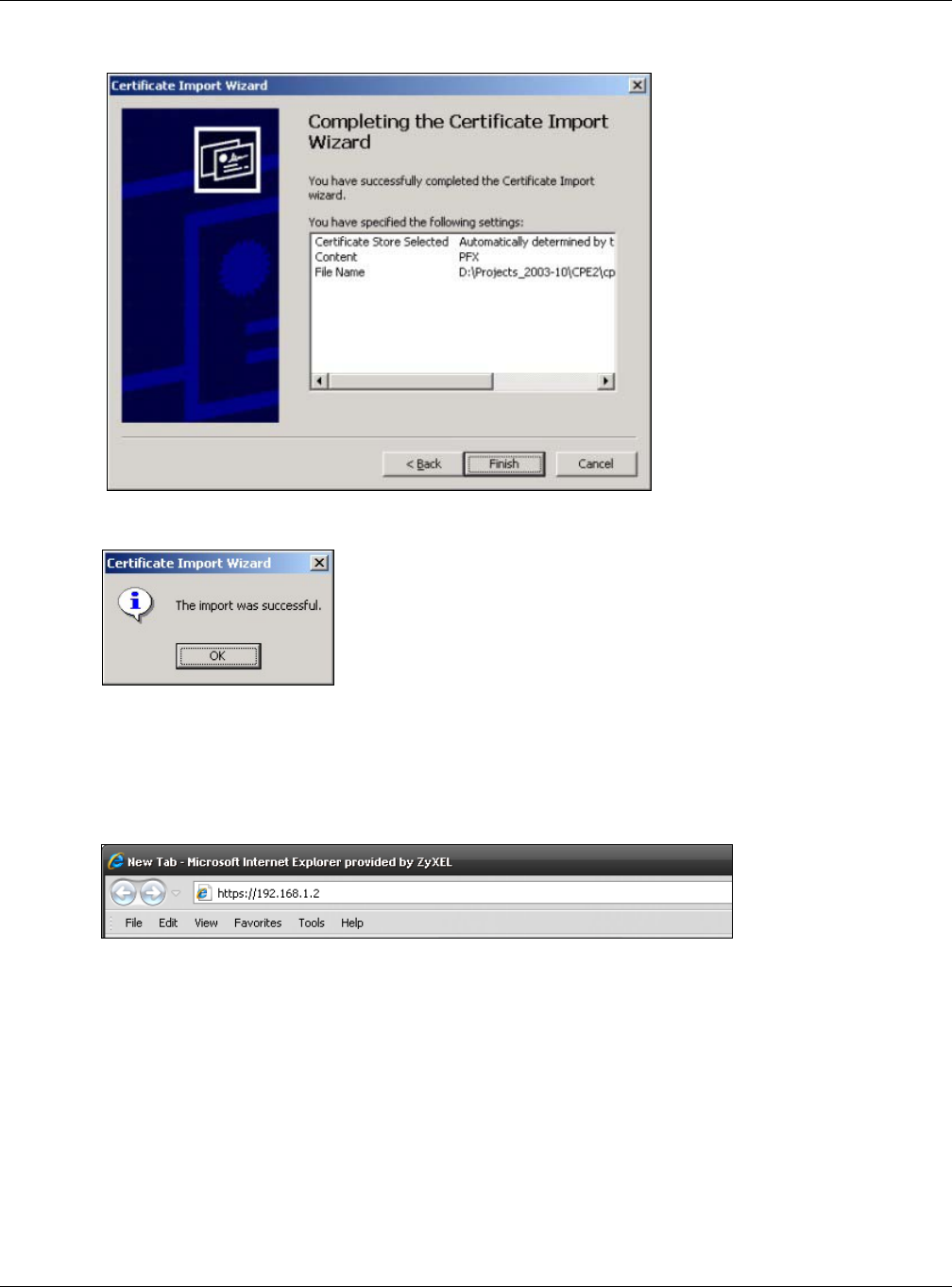
Chapter 14 System
NWA / WAC Series User’s Guide
162
5Click Finish to complete the wizard and begin the import process.
6You should see the following screen when the certificate is correctly installed on your computer.
14.4.5.7 Using a Certificate When Accessing the NWA/WAC
To access the NWA/WAC via HTTPS:
1Enter ‘https://NWA/WAC IP Address/’ in your browser’s web address field.
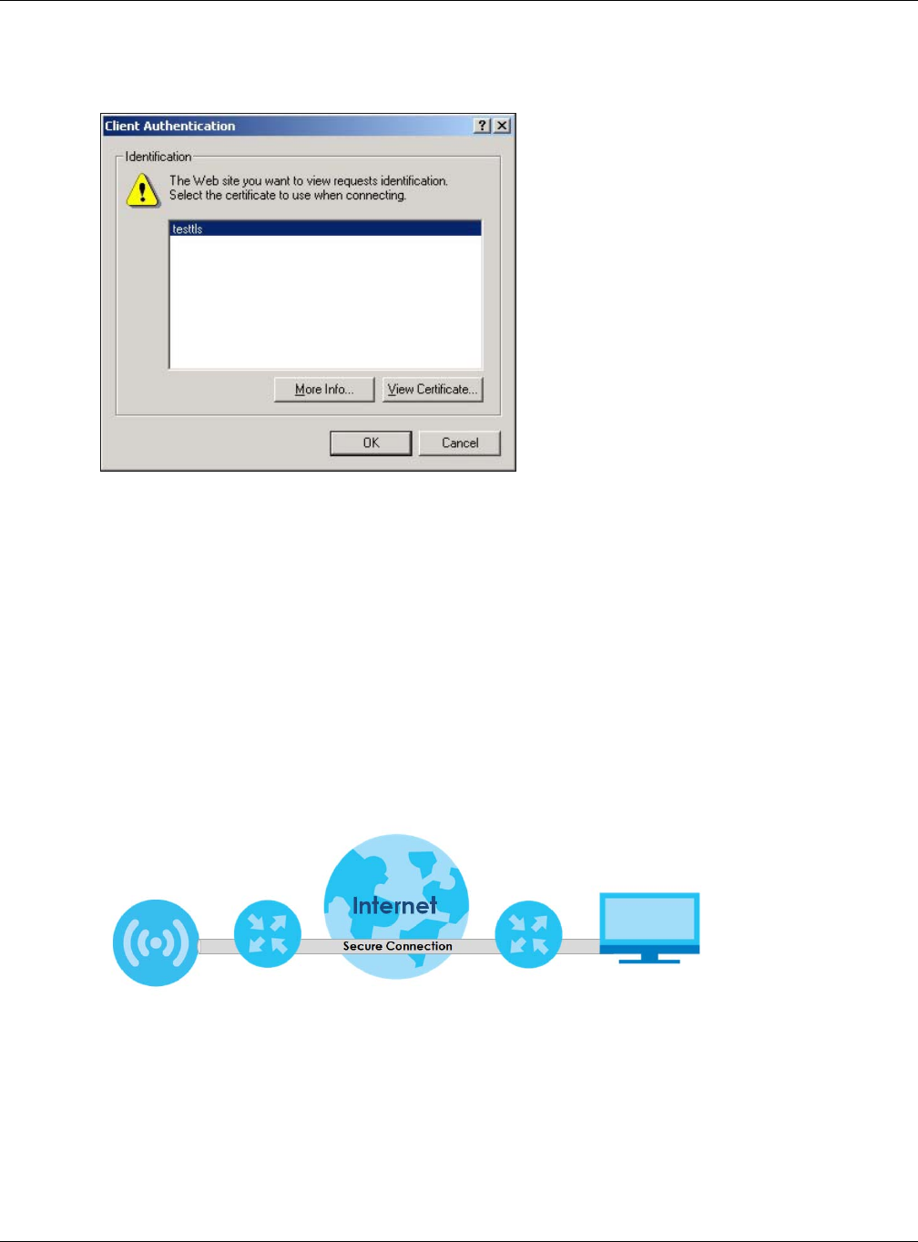
Chapter 14 System
NWA / WAC Series User’s Guide
163
2When Authenticate Client Certificates is selected on the NWA/WAC, the following screen asks you to
select a personal certificate to send to the NWA/WAC. This screen displays even if you only have a
single certificate as in the example.
3You next see the Web Configurator login screen.
14.5 SSH
You can use SSH (Secure SHell) to securely access the NWA/WAC’s command line interface.
SSH is a secure communication protocol that combines authentication and data encryption to provide
secure encrypted communication between two hosts over an unsecured network. In the following
figure, computer B on the Internet uses SSH to securely connect to the NWA/WAC (A) for a
management session.
Figure 101 SSH Communication Over the WAN Example
14.5.1 How SSH Works
The following figure is an example of how a secure connection is established between two remote hosts
using SSH v1.
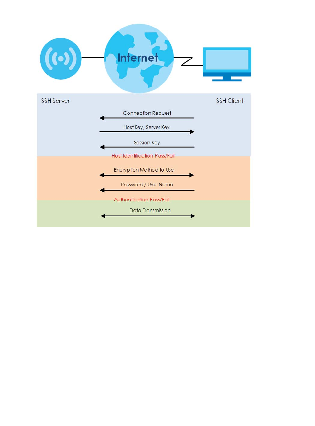
Chapter 14 System
NWA / WAC Series User’s Guide
164
Figure 102 How SSH v1 Works Example
1Host Identification
The SSH client sends a connection request to the SSH server. The server identifies itself with a host key.
The client encrypts a randomly generated session key with the host key and server key and sends the
result back to the server.
The client automatically saves any new server public keys. In subsequent connections, the server
public key is checked against the saved version on the client computer.
2Encryption Method
Once the identification is verified, both the client and server must agree on the type of encryption
method to use.
3Authentication and Data Transmission
After the identification is verified and data encryption activated, a secure tunnel is established
between the client and the server. The client then sends its authentication information (user name
and password) to the server to log in to the server.
14.5.2 SSH Implementation on the NWA/WAC
Your NWA/WAC supports SSH versions 1 and 2 using RSA authentication and four encryption methods
(AES, 3DES, Archfour, and Blowfish). The SSH server is implemented on the NWA/WAC for management
using port 22 (by default).
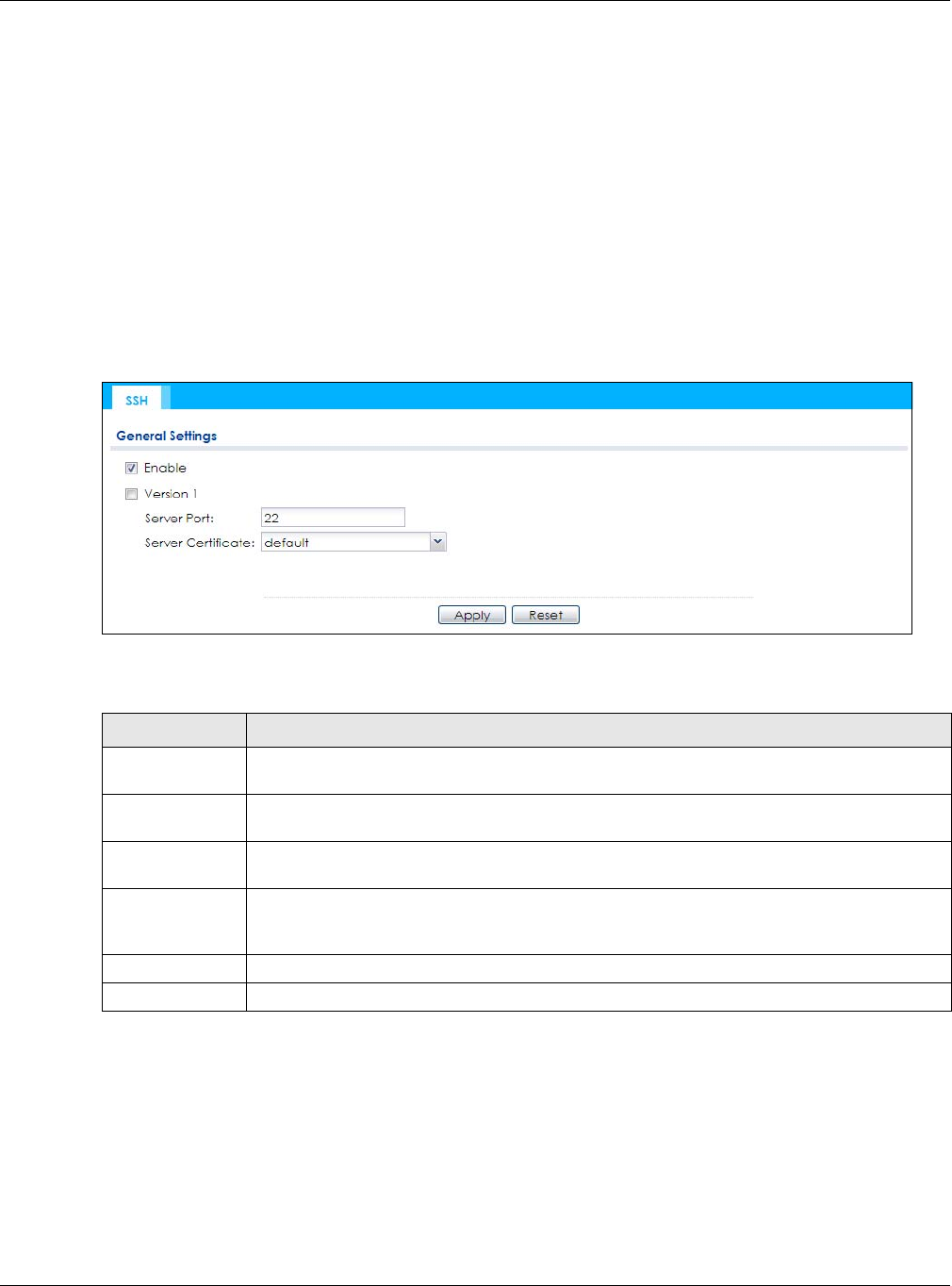
Chapter 14 System
NWA / WAC Series User’s Guide
165
14.5.3 Requirements for Using SSH
You must install an SSH client program on a client computer (Windows or Linux operating system) that is
used to connect to the NWA/WAC over SSH.
14.5.4 Configuring SSH
Click Configuration > System > SSH to open the following screen. Use this screen to configure your NWA/
WAC’s Secure Shell settings.
Note: It is recommended that you disable Telnet and FTP when you configure SSH for secure
connections.
Figure 103 Configuration > System > SSH
The following table describes the labels in this screen.
14.5.5 Examples of Secure Telnet Using SSH
This section shows two examples using a command interface and a graphical interface SSH client
program to remotely access the NWA/WAC. The configuration and connection steps are similar for most
SSH client programs. Refer to your SSH client program user’s guide.
14.5.5.1 Example 1: Microsoft Windows
This section describes how to access the NWA/WAC using the Secure Shell Client program.
Table 74 Configuration > System > SSH
LABEL DESCRIPTION
Enable Select the check box to allow or disallow the computer with the IP address that matches the IP
address(es) in the Service Control table to access the NWA/WAC CLI using this service.
Version 1 Select the check box to have the NWA/WAC use both SSH version 1 and version 2 protocols. If
you clear the check box, the NWA/WAC uses only SSH version 2 protocol.
Server Port You may change the server port number for a service if needed, however you must use the
same port number in order to use that service for remote management.
Server Certificate Select the certificate whose corresponding private key is to be used to identify the NWA/WAC
for SSH connections. You must have certificates already configured in the My Certificates
screen.
Apply Click Apply to save your changes back to the NWA/WAC.
Reset Click Reset to return the screen to its last-saved settings.
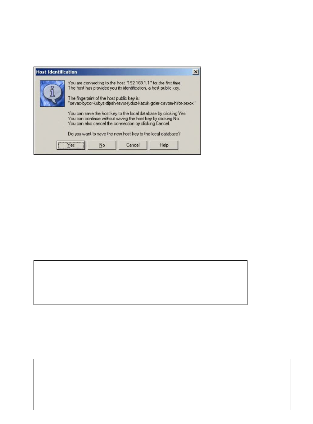
Chapter 14 System
NWA / WAC Series User’s Guide
166
1Launch the SSH client and specify the connection information (IP address, port number) for the NWA/
WAC.
2Configure the SSH client to accept connection using SSH version 1.
3A window displays prompting you to store the host key in you computer. Click Yes to continue.
Figure 104 SSH Example 1: Store Host Key
Enter the password to log in to the NWA/WAC. The CLI screen displays next.
14.5.5.2 Example 2: Linux
This section describes how to access the NWA/WAC using the OpenSSH client program that comes with
most Linux distributions.
1Test whether the SSH service is available on the NWA/WAC.
Enter “telnet 192.168.1.2 22” at a terminal prompt and press [ENTER]. The computer attempts to
connect to port 22 on the NWA/WAC (using the default IP address of 192.168.1.2).
A message displays indicating the SSH protocol version supported by the NWA/WAC.
Figure 105 SSH Example 2: Test
2Enter “ssh –1 192.168.1.2”. This command forces your computer to connect to the NWA/WAC using
SSH version 1. If this is the first time you are connecting to the NWA/WAC using SSH, a message displays
prompting you to save the host information of the NWA/WAC. Type “yes” and press [ENTER].
Then enter the password to log in to the NWA/WAC.
Figure 106 SSH Example 2: Log in
$ telnet 192.168.1.2 22
Trying 192.168.1.2...
Connected to 192.168.1.2.
Escape character is '^]'.
SSH-1.5-1.0.0
$ ssh –1 192.168.1.2
The authenticity of host '192.168.1.2 (192.168.1.2)' can't be established.
RSA1 key fingerprint is 21:6c:07:25:7e:f4:75:80:ec:af:bd:d4:3d:80:53:d1.
Are you sure you want to continue connecting (yes/no)? yes
Warning: Permanently added '192.168.1.2' (RSA1) to the list of known hosts.
Administrator@192.168.1.2's password:
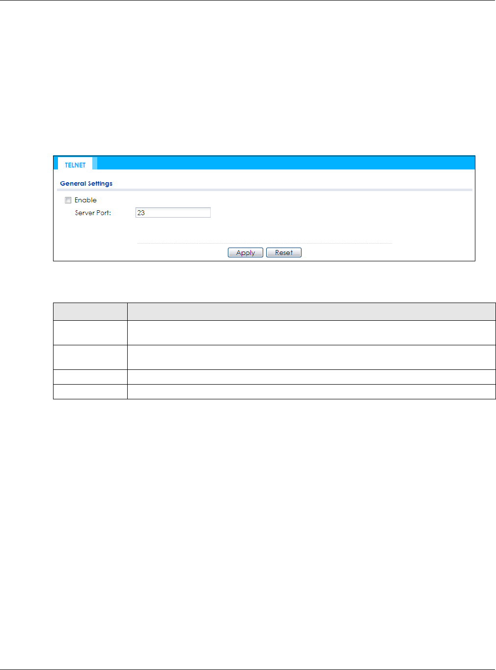
Chapter 14 System
NWA / WAC Series User’s Guide
167
3The CLI screen displays next.
14.6 Telnet
You can use Telnet to access the NWA/WAC’s command line interface. Click Configuration > System >
TELNET to configure your NWA/WAC for remote Telnet access. Use this screen to enable or disable Telnet
and set the server port number.
Figure 107 Configuration > System > TELNET
The following table describes the labels in this screen.
14.7 FTP
You can upload and download the NWA/WAC’s firmware and configuration files using FTP. To use this
feature, your computer must have an FTP client. See Chapter 16 on page 185 for more information
about firmware and configuration files.
To change your NWA/WAC’s FTP settings, click Configuration > System > FTP tab. The screen appears as
shown. Use this screen to specify FTP settings.
Table 75 Configuration > System > TELNET
LABEL DESCRIPTION
Enable Select the check box to allow or disallow the computer with the IP address that matches the IP
address(es) in the Service Control table to access the NWA/WAC CLI using this service.
Server Port You may change the server port number for a service if needed, however you must use the
same port number in order to use that service for remote management.
Apply Click Apply to save your changes back to the NWA/WAC.
Reset Click Reset to return the screen to its last-saved settings.
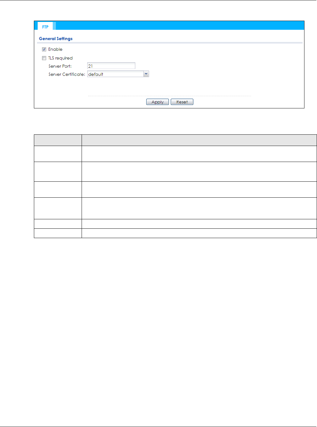
Chapter 14 System
NWA / WAC Series User’s Guide
168
Figure 108 Configuration > System > FTP
The following table describes the labels in this screen.
14.8 SNMP
Simple Network Management Protocol is a protocol used for exchanging management information
between network devices. Your NWA/WAC supports SNMP agent functionality, which allows a manager
station to manage and monitor the NWA/WAC through the network. The NWA/WAC supports SNMP
version one (SNMPv1), version two (SNMPv2c), and version three (SNMPv3). The next figure illustrates an
SNMP management operation.
Table 76 Configuration > System > FTP
LABEL DESCRIPTION
Enable Select the check box to allow or disallow the computer with the IP address that matches the IP
address(es) in the Service Control table to access the NWA/WAC using this service.
TLS required Select the check box to use FTP over TLS (Transport Layer Security) to encrypt communication.
This implements TLS as a security mechanism to secure FTP clients and/or servers.
Server Port You may change the server port number for a service if needed, however you must use the
same port number in order to use that service for remote management.
Server Certificate Select the certificate whose corresponding private key is to be used to identify the NWA/WAC
for FTP connections. You must have certificates already configured in the My Certificates
screen.
Apply Click Apply to save your changes back to the NWA/WAC.
Reset Click Reset to return the screen to its last-saved settings.
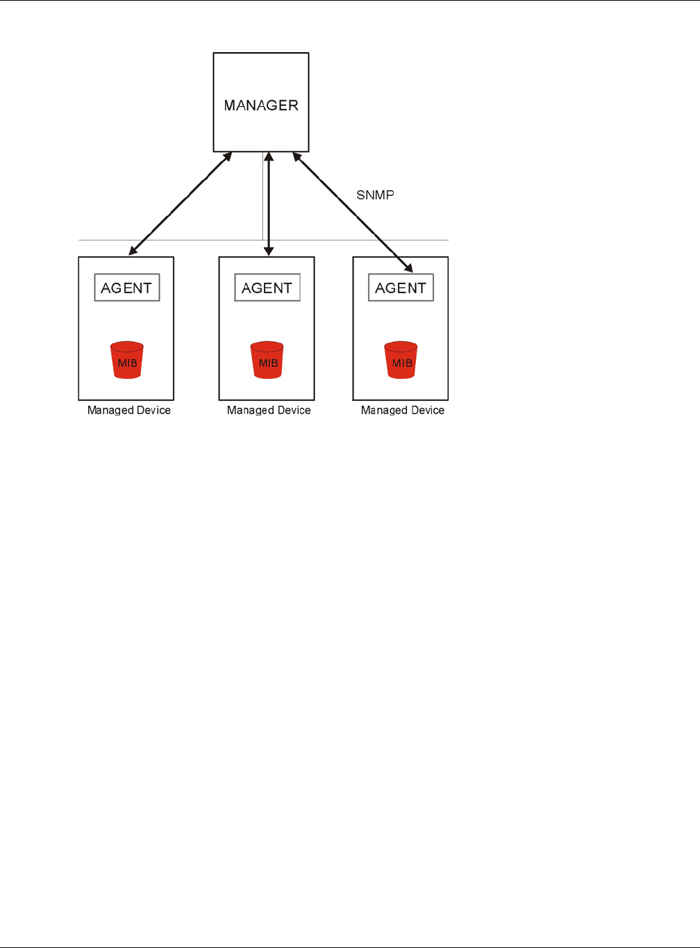
Chapter 14 System
NWA / WAC Series User’s Guide
169
Figure 109 SNMP Management Model
An SNMP managed network consists of two main types of component: agents and a manager.
An agent is a management software module that resides in a managed device (the NWA/WAC). An
agent translates the local management information from the managed device into a form compatible
with SNMP. The manager is the console through which network administrators perform network
management functions. It executes applications that control and monitor managed devices.
The managed devices contain object variables/managed objects that define each piece of
information to be collected about a device. Examples of variables include such as number of packets
received, node port status etc. A Management Information Base (MIB) is a collection of managed
objects. SNMP allows a manager and agents to communicate for the purpose of accessing these
objects.
SNMP itself is a simple request/response protocol based on the manager/agent model. The manager
issues a request and the agent returns responses using the following protocol operations:
• Get - Allows the manager to retrieve an object variable from the agent.
• GetNext - Allows the manager to retrieve the next object variable from a table or list within an agent.
In SNMPv1, when a manager wants to retrieve all elements of a table from an agent, it initiates a Get
operation, followed by a series of GetNext operations.
• Set - Allows the manager to set values for object variables within an agent.
• Trap - Used by the agent to inform the manager of some events.
14.8.1 Supported MIBs
The NWA/WAC supports MIB II that is defined in RFC-1213 and RFC-1215. The NWA/WAC also supports
private MIBs (ZYXEL-ES-CAPWAP.MIB, ZYXEL-ES-COMMON.MIB, ZYXEL-ES-ZyXELAPMgmt.MIB, ZYXEL-ES-
PROWLAN.MIB, ZYXEL-ES-RFMGMT.MIB, ZYXEL-ES-SMI.MIB, and ZYXEL-ES-WIRELESS.MIB) to collect
information about CPU and memory usage and VPN total throughput. The focus of the MIBs is to let

Chapter 14 System
NWA / WAC Series User’s Guide
170
administrators collect statistical data and monitor status and performance. You can download the
NWA/WAC’s MIBs from www.zyxel.com.
14.8.2 SNMP Traps
The NWA/WAC will send traps to the SNMP manager when any one of the following events occurs.
14.8.3 Configuring SNMP
To change your NWA/WAC’s SNMP settings, click Configuration > System > SNMP tab. The screen
appears as shown. Use this screen to configure your SNMP settings. You can also configure user profiles
that define allowed SNMPv3 access.
Figure 110 Configuration > System > SNMP
The following table describes the labels in this screen.
Table 77 SNMP Traps
OBJECT LABEL OBJECT ID DESCRIPTION
linkDown 1.3.6.1.6.3.1.1.5.3 This trap is sent when the Ethernet link is down.
linkUp 1.3.6.1.6.3.1.1.5.4 This trap is sent when the Ethernet link is up.
authenticationFailure 1.3.6.1.6.3.1.1.5.5 This trap is sent when an SNMP request comes from non-
authenticated hosts.
Table 78 Configuration > System > SNMP
LABEL DESCRIPTION
Enable Select the check box to allow or disallow users to access the NWA/WAC using SNMP.
Server Port You may change the server port number for a service if needed, however you must use the
same port number in order to use that service for remote management.
Trap
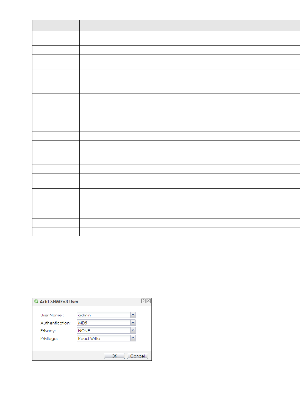
Chapter 14 System
NWA / WAC Series User’s Guide
171
14.8.4 Adding or Editing an SNMPv3 User Profile
This screen allows you to add or edit an SNMPv3 user profile. To access this screen, click the
Configuration > System > SNMP screen’s Add button or select a SNMPv3 user profile from the list and
click the Edit button.
Figure 111 Configuration > System > SNMP > Add
Community Type the trap community, which is the password sent with each trap to the SNMP manager.
The default is public and allows all requests.
Destination Type the IP address of the station to send your SNMP traps to.
Trap Wireless
Event
Select this to have the NWA/WAC send a trap to the SNMP manager when a wireless client is
connected to or disconnected from the NWA/WAC.
SNMPv2c Select this to allow SNMP managers using SNMPv2c to access the NWA/WAC.
Get Community Enter the Get Community, which is the password for the incoming Get and GetNext requests
from the management station. The default is public and allows all requests.
Set Community Enter the Set community, which is the password for incoming Set requests from the
management station. The default is private and allows all requests.
SNMPv3 Select this to allow SNMP managers using SNMPv3 to access the NWA/WAC.
Add Click this to create a new entry. Select an entry and click Add to create a new entry after the
selected entry.
Edit Double-click an entry or select it and click Edit to be able to modify the entry’s settings.
Remove To remove an entry, select it and click Remove. The NWA/WAC confirms you want to remove it
before doing so. Note that subsequent entries move up by one when you take this action.
#This the index number of an SNMPv3 user profile.
User Name This is the name of the user for which this SNMPv3 user profile is configured.
Authentication This field displays the type of authentication the SNMPv3 user must use to connect to the NWA/
WAC using this SNMPv3 user profile.
Privacy This field displays the type of encryption the SNMPv3 user must use to connect to the NWA/
WAC using this SNMPv3 user profile.
Privilege This field displays whether the SNMPv3 user can have read-only or read and write access to
the NWA/WAC using this SNMPv3 user profile.
Apply Click Apply to save your changes back to the NWA/WAC.
Reset Click Reset to return the screen to its last-saved settings.
Table 78 Configuration > System > SNMP (continued)
LABEL DESCRIPTION

Chapter 14 System
NWA / WAC Series User’s Guide
172
The following table describes the labels in this screen.
Table 79 Configuration > System > SNMP
LABEL DESCRIPTION
User Name Select the user name of the user account for which this SNMPv3 user profile is configured.
Authentication Select the type of authentication the SNMPv3 user must use to connect to the NWA/WAC
using this SNMPv3 user profile.
Select MD5 to require the SNMPv3 user’s password be encrypted by MD5 for authentication.
Select SHA to require the SNMPv3 user’s password be encrypted by SHA for authentication.
Privacy Select the type of encryption the SNMPv3 user must use to connect to the NWA/WAC using this
SNMPv3 user profile.
Select NONE to not encrypt the SNMPv3 communications.
Select DES to use DES to encrypt the SNMPv3 communications.
Select AES to use AES to encrypt the SNMPv3 communications.
Privilege Select whether the SNMPv3 user can have read-only or read and write access to the NWA/
WAC using this SNMPv3 user profile.
OK Click OK to save your changes back to the NWA/WAC.
Cancel Click Cancel to exit this screen without saving your changes.

NWA / WAC Series User’s Guide
173
CHAPTER 15
Log and Report
15.1 Overview
Use the system screens to configure daily reporting and log settings.
15.1.1 What You Can Do In this Chapter
• The Email Daily Report screen (Section 15.2 on page 173) configures how and where to send daily
reports and what reports to send.
• The Log Setting screens (Section 15.3 on page 175) specify which logs are e-mailed, where they are e-
mailed, and how often they are e-mailed.
15.2 Email Daily Report
Use this screen to start or stop data collection and view various statistics about traffic passing through
your NWA/WAC.
Note: Data collection may decrease the NWA/WAC’s traffic throughput rate.
Click Configuration > Log & Report > Email Daily Report to display the following screen. Configure this
screen to have the NWA/WAC e-mail you system statistics every day.
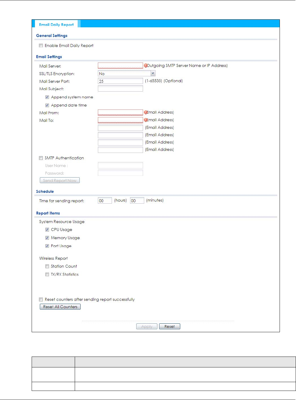
Chapter 15 Log and Report
NWA / WAC Series User’s Guide
174
Figure 112 Configuration > Log & Report > Email Daily Report
The following table describes the labels in this screen.
Table 80 Configuration > Log & Report > Email Daily Report
LABEL DESCRIPTION
Enable Email
Daily Report
Select this to send reports by e-mail every day.
Mail Server Type the name or IP address of the outgoing SMTP server.

Chapter 15 Log and Report
NWA / WAC Series User’s Guide
175
15.3 Log Setting
These screens control log messages and alerts. A log message stores the information for viewing (for
example, in the Monitor > View Log screen) or regular e-mailing later, and an alert is e-mailed
immediately. Usually, alerts are used for events that require more serious attention, such as system errors
and attacks.
The NWA/WAC provides a system log and supports e-mail profiles and remote syslog servers. The system
log is available on the View Log screen, the e-mail profiles are used to mail log messages to the
specified destinations, and the other four logs are stored on specified syslog servers.
The Log Setting tab also controls what information is saved in each log. For the system log, you can also
specify which log messages are e-mailed, where they are e-mailed, and how often they are e-mailed.
For alerts, the Log Setting screen controls which events generate alerts and where alerts are e-mailed.
The Log Setting screen provides a summary of all the settings. You can use the Edit Log Setting screen to
maintain the detailed settings (such as log categories, e-mail addresses, server names, etc.) for any log.
SSL/TLS
Encryption
Select SSL/TLS to use Secure Sockets Layer (SSL) or Transport Layer Security (TLS) if you want
encrypted communications between the mail server and the NWA/WAC.
Select STARTTLS to upgrade a plain text connection to a secure connection using SSL/TLS.
Select No to not encrypt the communications.
Mail Server Port Enter the same port number here as is on the mail server for mail traffic.
Mail Subject Type the subject line for the outgoing e-mail. Select Append system name to add the NWA/
WAC’s system name to the subject. Select Append date time to add the NWA/WAC’s system
date and time to the subject.
Mail From Type the e-mail address from which the outgoing e-mail is delivered. This address is used in
replies.
Mail To Type the e-mail address (or addresses) to which the outgoing e-mail is delivered.
SMTP
Authentication
Select this check box if it is necessary to provide a user name and password to the SMTP server.
User Name This box is effective when you select the SMTP Authentication check box. Type the user name to
provide to the SMTP server when the log is e-mailed.
Password This box is effective when you select the SMTP Authentication check box. Type the password to
provide to the SMTP server when the log is e-mailed.
Send Report
Now
Click this button to have the NWA/WAC send the daily e-mail report immediately.
Time for sending
report
Select the time of day (hours and minutes) when the log is e-mailed. Use 24-hour notation.
Report Items Select the information to include in the report. Select Reset counters after sending report
successfully if you only want to see statistics for a 24 hour period.
Reset All
Counters
Click this to discard all report data and start all of the counters over at zero.
Apply Click Apply to save your changes back to the NWA/WAC.
Reset Click Reset to return the screen to its last-saved settings.
Table 80 Configuration > Log & Report > Email Daily Report (continued)
LABEL DESCRIPTION
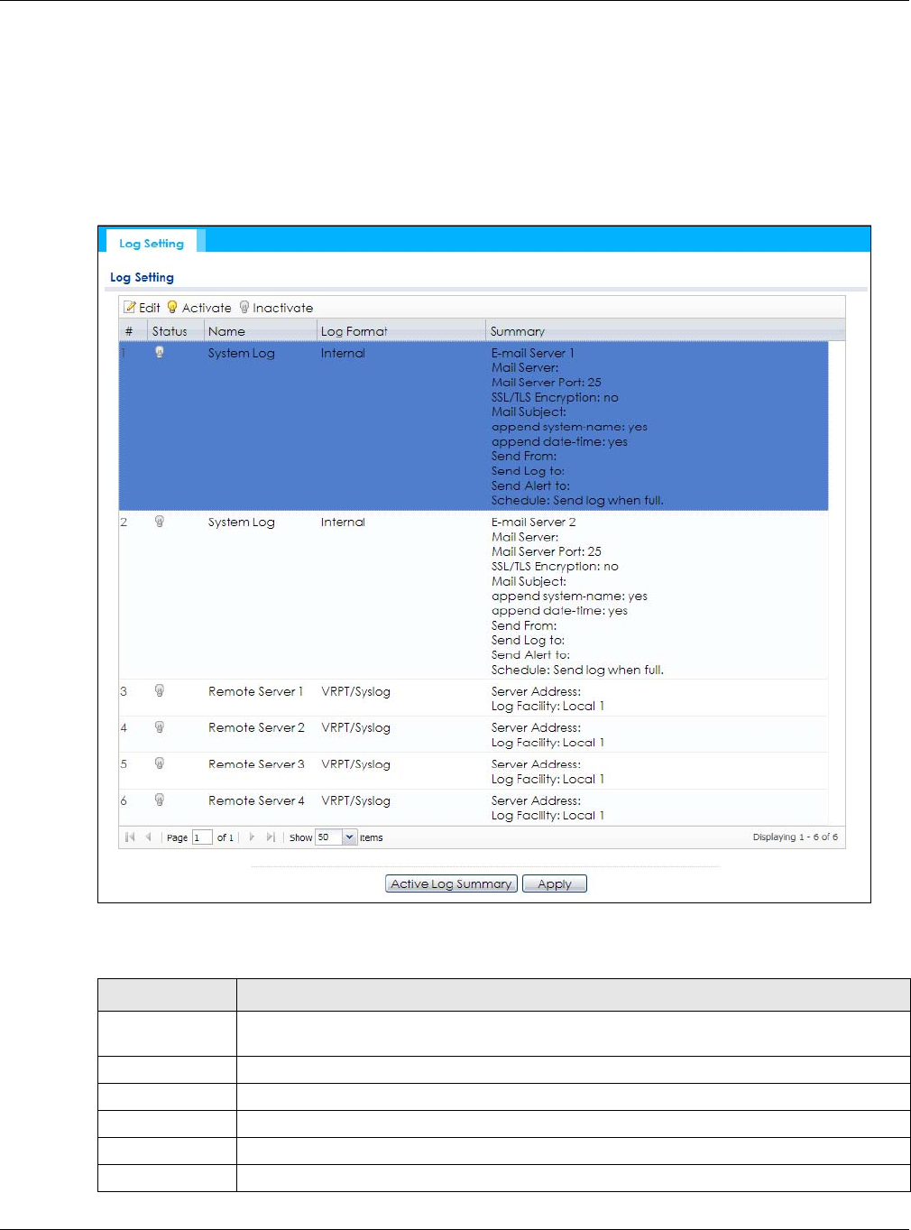
Chapter 15 Log and Report
NWA / WAC Series User’s Guide
176
Alternatively, if you want to edit what events is included in each log, you can also use the Active Log
Summary screen to edit this information for all logs at the same time.
15.3.1 Log Setting Screen
To access this screen, click Configuration > Log & Report > Log Setting.
Figure 113 Configuration > Log & Report > Log Setting
The following table describes the labels in this screen.
Table 81 Configuration > Log & Report > Log Setting
LABEL DESCRIPTION
Edit Double-click an entry or select it and click Edit to open a screen where you can modify the
entry’s settings.
Activate To turn on an entry, select it and click Activate.
Inactivate To turn off an entry, select it and click Inactivate.
# This field is a sequential value, and it is not associated with a specific log.
Status This field shows whether the log is active or not.
Name This field displays the name of the log (system log or one of the remote servers).

Chapter 15 Log and Report
NWA / WAC Series User’s Guide
177
15.3.2 Edit System Log Settings
This screen controls the detailed settings for each log in the system log (which includes the e-mail
profiles). Select a system log entry in the Log Setting screen and click the Edit icon.
Log Format This field displays the format of the log.
Internal - system log; you can view the log on the View Log tab.
VRPT/Syslog - Zyxel’s Vantage Report, syslog-compatible format.
CEF/Syslog - Common Event Format, syslog-compatible format.
Summary This field is a summary of the settings for each log.
Active Log
Summary
Click this button to open the Active Log Summary screen.
Apply Click this button to save your changes (activate and deactivate logs) and make them take
effect.
Table 81 Configuration > Log & Report > Log Setting (continued)
LABEL DESCRIPTION
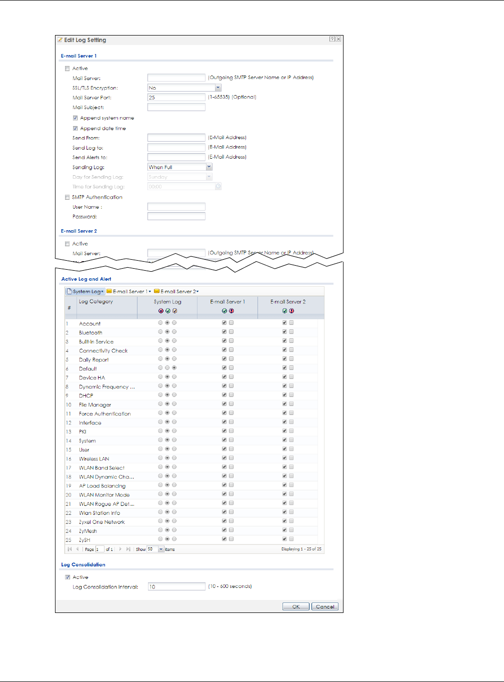
Chapter 15 Log and Report
NWA / WAC Series User’s Guide
178
Figure 114 Configuration > Log & Report > Log Setting > Edit System Log Setting

Chapter 15 Log and Report
NWA / WAC Series User’s Guide
179
The following table describes the labels in this screen.
Table 82 Configuration > Log & Report > Log Setting > Edit System Log Setting
LABEL DESCRIPTION
E-Mail Server 1/2
Active Select this to send log messages and alerts according to the information in this section.
You specify what kinds of log messages are included in log information and what kinds of
log messages are included in alerts in the Active Log and Alert section.
Mail Server Type the name or IP address of the outgoing SMTP server.
SSL/TLS Encryption Select SSL/TLS to use Secure Sockets Layer (SSL) or Transport Layer Security (TLS) if you
want encrypted communications between the mail server and the NWA/WAC.
Select STARTTLS to upgrade a plain text connection to a secure connection using SSL/TLS.
Select No to not encrypt the communications.
Mail Server Port Enter the same port number here as is on the mail server for mail traffic.
Mail Subject Type the subject line for the outgoing e-mail. Select Append system name to add the
NWA/WAC’s system name to the subject. Select Append date time to add the NWA/
WAC’s system date and time to the subject.
Send From Type the e-mail address from which the outgoing e-mail is delivered. This address is used
in replies.
Send Log To Type the e-mail address to which the outgoing e-mail is delivered.
Send Alerts To Type the e-mail address to which alerts are delivered.
Sending Log Select how often log information is e-mailed. Choices are: When Full, Hourly and When
Full, Daily and When Full, and Weekly and When Full.
Day for Sending Log This field is available if the log is e-mailed weekly. Select the day of the week the log is e-
mailed.
Time for Sending
Log This field is available if the log is e-mailed weekly or daily. Select the time of day (hours
and minutes) when the log is e-mailed. Use 24-hour notation.
SMTP
Authentication Select this check box if it is necessary to provide a user name and password to the SMTP
server.
User Name This box is effective when you select the SMTP Authentication check box. Type the user
name to provide to the SMTP server when the log is e-mailed.
Password This box is effective when you select the SMTP Authentication check box. Type the
password to provide to the SMTP server when the log is e-mailed.
Active Log and Alert
System log Use the System Log drop-down list to change the log settings for all of the log categories.
disable all logs (red X) - do not log any information for any category for the system log or
e-mail any logs to e-mail server 1 or 2.
enable normal logs (green check mark) - create log messages and alerts for all
categories for the system log. If e-mail server 1 or 2 also has normal logs enabled, the
NWA/WAC will e-mail logs to them.
enable normal logs and debug logs (yellow check mark) - create log messages, alerts,
and debugging information for all categories. The NWA/WAC does not e-mail
debugging information, even if this setting is selected.

Chapter 15 Log and Report
NWA / WAC Series User’s Guide
180
E-mail Server 1 Use the E-Mail Server 1 drop-down list to change the settings for e-mailing logs to e-mail
server 1 for all log categories.
Using the System Log drop-down list to disable all logs overrides your e-mail server 1
settings.
enable normal logs (green check mark) - e-mail log messages for all categories to e-mail
server 1.
enable alert logs (red exclamation point) - e-mail alerts for all categories to e-mail server
1.
E-mail Server 2 Use the E-Mail Server 2 drop-down list to change the settings for e-mailing logs to e-mail
server 2 for all log categories.
Using the System Log drop-down list to disable all logs overrides your e-mail server 2
settings.
enable normal logs (green check mark) - e-mail log messages for all categories to e-mail
server 2.
enable alert logs (red exclamation point) - e-mail alerts for all categories to e-mail server
2.
# This field is a sequential value, and it is not associated with a specific address.
Log Category This field displays each category of messages. It is the same value used in the Display
and Category fields in the View Log tab. The Default category includes debugging
messages generated by open source software.
System log Select which events you want to log by Log Category. There are three choices:
disable all logs (red X) - do not log any information from this category
enable normal logs (green checkmark) - create log messages and alerts from this
category
enable normal logs and debug logs (yellow check mark) - create log messages, alerts,
and debugging information from this category; the NWA/WAC does not e-mail
debugging information, however, even if this setting is selected.
E-mail Server 1 Select whether each category of events should be included in the log messages when it
is e-mailed (green check mark) and/or in alerts (red exclamation point) for the e-mail
settings specified in E-Mail Server 1. The NWA/WAC does not e-mail debugging
information, even if it is recorded in the System log.
E-mail Server 2 Select whether each category of events should be included in log messages when it is e-
mailed (green check mark) and/or in alerts (red exclamation point) for the e-mail
settings specified in E-Mail Server 2. The NWA/WAC does not e-mail debugging
information, even if it is recorded in the System log.
Log Consolidation
Active Select this to activate log consolidation. Log consolidation aggregates multiple log
messages that arrive within the specified Log Consolidation Interval. In the View Log tab,
the text “[count=x]”, where x is the number of original log messages, is appended at the
end of the Message field, when multiple log messages were aggregated.
Log Consolidation
Interval Type how often, in seconds, to consolidate log information. If the same log message
appears multiple times, it is aggregated into one log message with the text “[count=x]”,
where x is the number of original log messages, appended at the end of the Message
field.
OK Click this to save your changes and return to the previous screen.
Cancel Click this to return to the previous screen without saving your changes.
Table 82 Configuration > Log & Report > Log Setting > Edit System Log Setting (continued)
LABEL DESCRIPTION
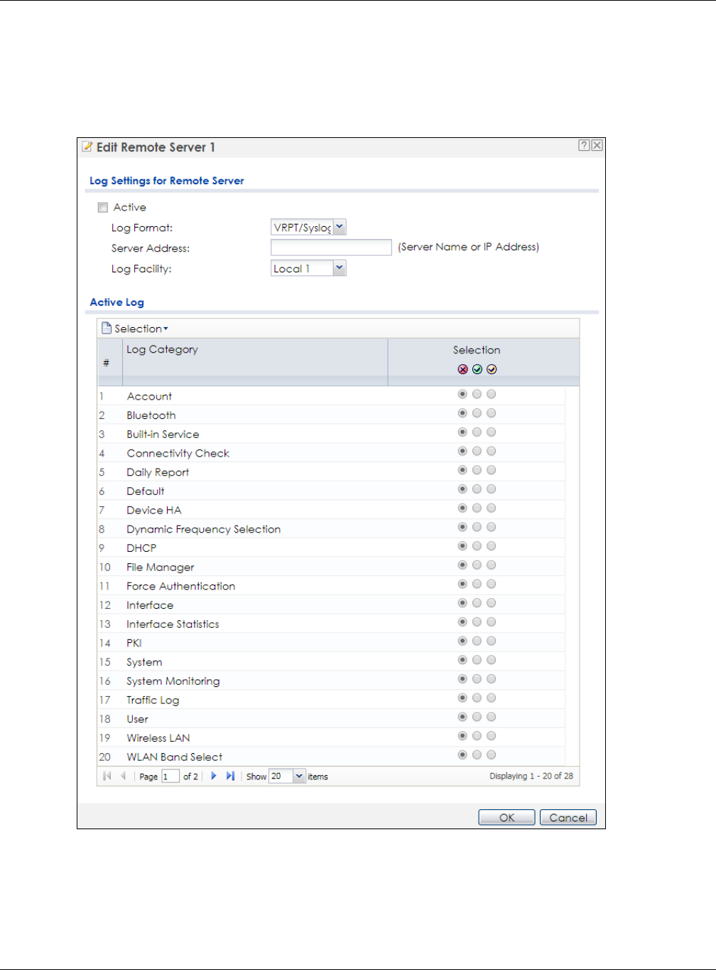
Chapter 15 Log and Report
NWA / WAC Series User’s Guide
181
15.3.3 Edit Remote Server
This screen controls the settings for each log in the remote server (syslog). Select a remote server entry in
the Log Setting screen and click the Edit icon.
Figure 115 Configuration > Log & Report > Log Setting > Edit Remote Server

Chapter 15 Log and Report
NWA / WAC Series User’s Guide
182
The following table describes the labels in this screen.
15.3.4 Active Log Summary
This screen allows you to view and to edit what information is included in the system log, e-mail profiles,
and remote servers at the same time. It does not let you change other log settings (for example, where
and how often log information is e-mailed or remote server names). To access this screen, go to the Log
Setting screen, and click the Active Log Summary button.
Table 83 Configuration > Log & Report > Log Setting > Edit Remote Server
LABEL DESCRIPTION
Log Settings for
Remote Server
Active Select this check box to send log information according to the information in this section. You
specify what kinds of messages are included in log information in the Active Log section.
Log Format This field displays the format of the log information. It is read-only.
VRPT/Syslog - Zyxel’s Vantage Report, syslog-compatible format.
CEF/Syslog - Common Event Format, syslog-compatible format.
Server
Address Type the server name or the IP address of the syslog server to which to send log information.
Log Facility Select a log facility. The log facility allows you to log the messages to different files in the syslog
server. Please see the documentation for your syslog program for more information.
Active Log
Selection Use the Selection drop-down list to change the log settings for all of the log categories.
disable all logs (red X) - do not send the remote server logs for any log category.
enable normal logs (green check mark) - send the remote server log messages and alerts for all
log categories.
enable normal logs and debug logs (yellow check mark) - send the remote server log
messages, alerts, and debugging information for all log categories.
# This field is a sequential value, and it is not associated with a specific address.
Log Category This field displays each category of messages. It is the same value used in the Display and
Category fields in the View Log tab. The Default category includes debugging messages
generated by open source software.
Selection Select what information you want to log from each Log Category (except All Logs; see below).
Choices are:
disable all logs (red X) - do not log any information from this category
enable normal logs (green checkmark) - log regular information and alerts from this category
enable normal logs and debug logs (yellow check mark) - log regular information, alerts, and
debugging information from this category
OK Click this to save your changes and return to the previous screen.
Cancel Click this to return to the previous screen without saving your changes.
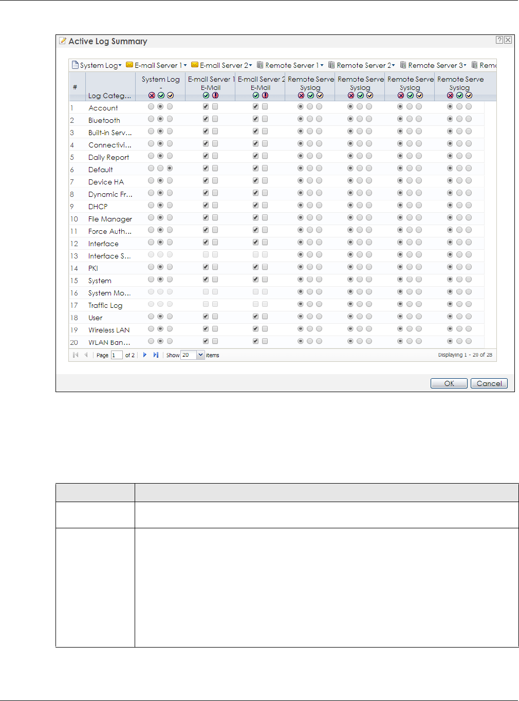
Chapter 15 Log and Report
NWA / WAC Series User’s Guide
183
Figure 116 Active Log Summary
This screen provides a different view and a different way of indicating which messages are included in
each log and each alert. (The Default category includes debugging messages generated by open
source software.)
The following table describes the fields in this screen.
Table 84 Configuration > Log & Report > Log Setting > Active Log Summary
LABEL DESCRIPTION
Active Log
Summary
If the NWA/WAC is set to controller mode, the AC section controls logs generated by the
controller and the AP section controls logs generated by the managed APs.
System log Use the System Log drop-down list to change the log settings for all of the log categories.
disable all logs (red X) - do not log any information for any category for the system log or e-mail
any logs to e-mail server 1 or 2.
enable normal logs (green check mark) - create log messages and alerts for all categories for
the system log. If e-mail server 1 or 2 also has normal logs enabled, the NWA/WAC will e-mail
logs to them.
enable normal logs and debug logs (yellow check mark) - create log messages, alerts, and
debugging information for all categories. The NWA/WAC does not e-mail debugging
information, even if this setting is selected.

Chapter 15 Log and Report
NWA / WAC Series User’s Guide
184
E-mail Server 1 Use the E-Mail Server 1 drop-down list to change the settings for e-mailing logs to e-mail server
1 for all log categories.
Using the System Log drop-down list to disable all logs overrides your e-mail server 1 settings.
enable normal logs (green check mark) - e-mail log messages for all categories to e-mail server
1.
enable alert logs (red exclamation point) - e-mail alerts for all categories to e-mail server 1.
E-mail Server 2 Use the E-Mail Server 2 drop-down list to change the settings for e-mailing logs to e-mail server
2 for all log categories.
Using the System Log drop-down list to disable all logs overrides your e-mail server 2 settings.
enable normal logs (green check mark) - e-mail log messages for all categories to e-mail server
2.
enable alert logs (red exclamation point) - e-mail alerts for all categories to e-mail server 2.
Remote Server
1~4
For each remote server, use the Selection drop-down list to change the log settings for all of the
log categories.
disable all logs (red X) - do not send the remote server logs for any log category.
enable normal logs (green check mark) - send the remote server log messages and alerts for all
log categories.
enable normal logs and debug logs (yellow check mark) - send the remote server log
messages, alerts, and debugging information for all log categories.
# This field is a sequential value, and it is not associated with a specific address.
Log Category This field displays each category of messages. It is the same value used in the Display and
Category fields in the View Log tab. The Default category includes debugging messages
generated by open source software.
System log Select which events you want to log by Log Category. There are three choices:
disable all logs (red X) - do not log any information from this category
enable normal logs (green checkmark) - create log messages and alerts from this category
enable normal logs and debug logs (yellow check mark) - create log messages, alerts, and
debugging information from this category; the NWA/WAC does not e-mail debugging
information, however, even if this setting is selected.
E-mail Server 1 E-
mail
Select whether each category of events should be included in the log messages when it is e-
mailed (green check mark) and/or in alerts (red exclamation point) for the e-mail settings
specified in E-Mail Server 1. The NWA/WAC does not e-mail debugging information, even if it is
recorded in the System log.
E-mail Server 2 E-
mail
Select whether each category of events should be included in log messages when it is e-
mailed (green check mark) and/or in alerts (red exclamation point) for the e-mail settings
specified in E-Mail Server 2. The NWA/WAC does not e-mail debugging information, even if it is
recorded in the System log.
Remote Server
1~4 Syslog
For each remote server, select what information you want to log from each Log Category
(except All Logs; see below). Choices are:
disable all logs (red X) - do not log any information from this category
enable normal logs (green checkmark) - log regular information and alerts from this category
enable normal logs and debug logs (yellow check mark) - log regular information, alerts, and
debugging information from this category
OK Click this to save your changes and return to the previous screen.
Cancel Click this to return to the previous screen without saving your changes.
Table 84 Configuration > Log & Report > Log Setting > Active Log Summary (continued)
LABEL DESCRIPTION

NWA / WAC Series User’s Guide
185
CHAPTER 16
File Manager
16.1 Overview
Configuration files define the NWA/WAC’s settings. Shell scripts are files of commands that you can store
on the NWA/WAC and run when you need them. You can apply a configuration file or run a shell script
without the NWA/WAC restarting. You can store multiple configuration files and shell script files on the
NWA/WAC. You can edit configuration files or shell scripts in a text editor and upload them to the NWA/
WAC. Configuration files use a .conf extension and shell scripts use a .zysh extension.
16.1.1 What You Can Do in this Chapter
• The Configuration File screen (Section 16.2 on page 186) stores and names configuration files. You
can also download and upload configuration files.
• The Firmware Package screen (Section 16.3 on page 191) checks your current firmware version and
uploads firmware to the NWA/WAC.
• The Shell Script screen (Section 16.4 on page 193) stores, names, downloads, uploads and runs shell
script files.
16.1.2 What you Need to Know
The following terms and concepts may help as you read this chapter.
Configuration Files and Shell Scripts
When you apply a configuration file, the NWA/WAC uses the factory default settings for any features
that the configuration file does not include. When you run a shell script, the NWA/WAC only applies the
commands that it contains. Other settings do not change.
These files have the same syntax, which is also identical to the way you run CLI commands manually. An
example is shown below.
Figure 117 Configuration File / Shell Script: Example
# enter configuration mode
configure terminal
# change administrator password
username admin password 4321 user-type admin
#configure default radio profile, change 2GHz channel to 11 & Tx output
power # to 50%
wlan-radio-profile default
2g-channel 11
output-power 50%
exit
write

Chapter 16 File Manager
NWA / WAC Series User’s Guide
186
While configuration files and shell scripts have the same syntax, the NWA/WAC applies configuration
files differently than it runs shell scripts. This is explained below.
You have to run the aforementioned example as a shell script because the first command is run in
Privilege mode. If you remove the first command, you have to run the example as a configuration file
because the rest of the commands are executed in Configuration mode.
Comments in Configuration Files or Shell Scripts
In a configuration file or shell script, use “#” or “!” as the first character of a command line to have the
NWA/WAC treat the line as a comment.
Your configuration files or shell scripts can use “exit” or a command line consisting of a single “!” to have
the NWA/WAC exit sub command mode.
Note: “exit” or “!'” must follow sub commands if it is to make the NWA/WAC exit sub
command mode.
In the following example lines 1 and 2 are comments. Line 7 exits sub command mode.
Errors in Configuration Files or Shell Scripts
When you apply a configuration file or run a shell script, the NWA/WAC processes the file line-by-line.
The NWA/WAC checks the first line and applies the line if no errors are detected. Then it continues with
the next line. If the NWA/WAC finds an error, it stops applying the configuration file or shell script and
generates a log.
You can change the way a configuration file or shell script is applied. Include setenv stop-on-error
off in the configuration file or shell script. The NWA/WAC ignores any errors in the configuration file or
shell script and applies all of the valid commands. The NWA/WAC still generates a log for any errors.
16.2 Configuration File
Click Maintenance > File Manager > Configuration File to open this screen. Use the Configuration File
screen to store, run, and name configuration files. You can also download configuration files from the
NWA/WAC to your computer and upload configuration files from your computer to the NWA/WAC.
Table 85 Configuration Files and Shell Scripts in the NWA/WAC
Configuration Files (.conf) Shell Scripts (.zysh)
• Resets to default configuration.
•Goes into CLI Configuration mode.
• Runs the commands in the configuration file.
•Goes into CLI Privilege mode.
• Runs the commands in the shell script.
! this is from Joe
# on 2010/12/05
wlan-ssid-profile default
ssid Joe-AP
qos wmm
security default
!
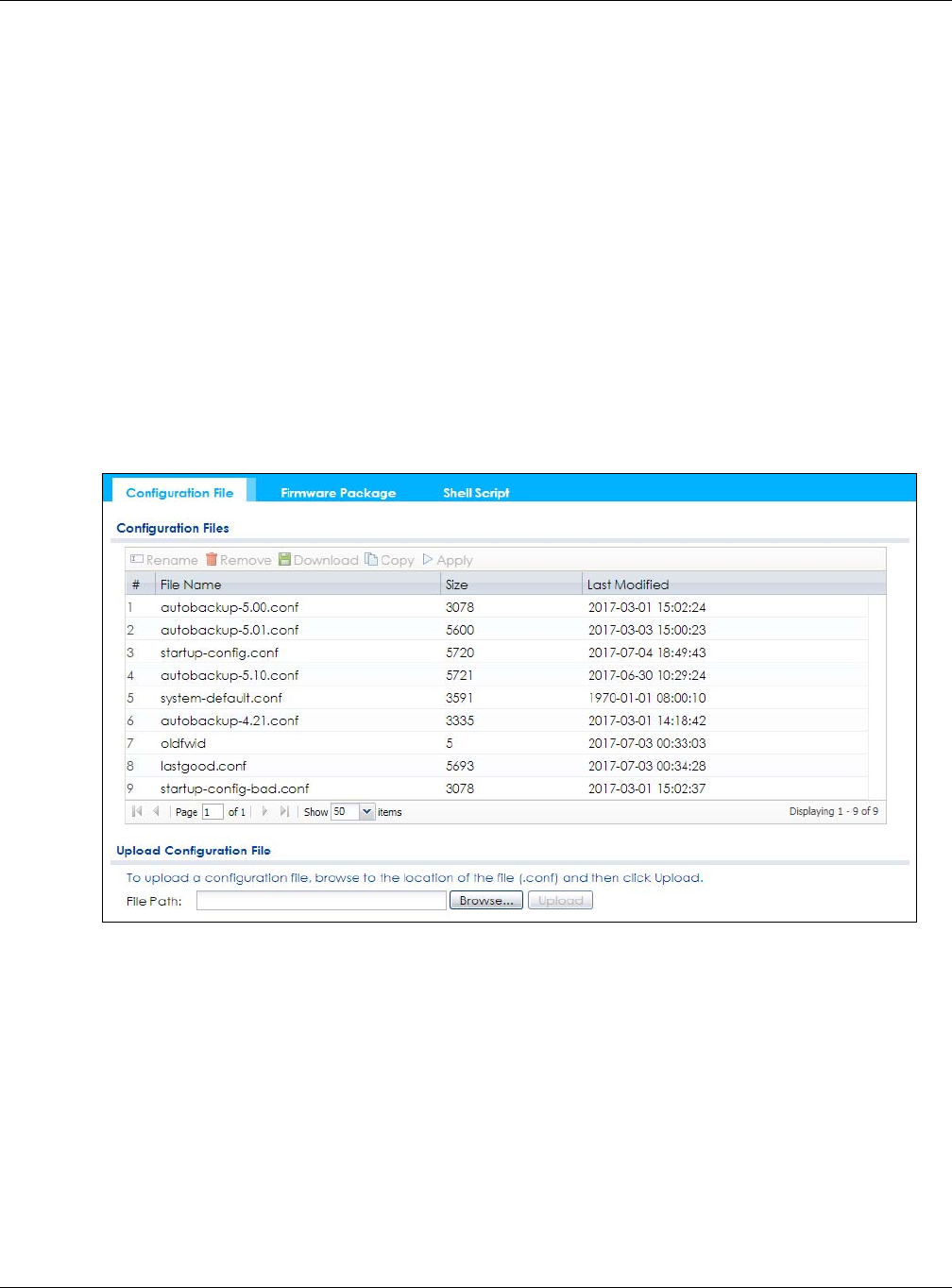
Chapter 16 File Manager
NWA / WAC Series User’s Guide
187
Once your NWA/WAC is configured and functioning properly, it is highly recommended that you back
up your configuration file before making further configuration changes. The backup configuration file
will be useful in case you need to return to your previous settings.
Configuration File Flow at Restart
• If there is not a startup-config.conf when you restart the NWA/WAC (whether through a management
interface or by physically turning the power off and back on), the NWA/WAC uses the system-
default.conf configuration file with the NWA/WAC’s default settings.
•If there is a startup-config.conf, the NWA/WAC checks it for errors and applies it. If there are no errors,
the NWA/WAC uses it and copies it to the lastgood.conf configuration file as a back up file. If there is
an error, the NWA/WAC generates a log and copies the startup-config.conf configuration file to the
startup-config-bad.conf configuration file and tries the existing lastgood.conf configuration file. If
there isn’t a lastgood.conf configuration file or it also has an error, the NWA/WAC applies the system-
default.conf configuration file.
• You can change the way the startup-config.conf file is applied. Include the setenv-startup stop-
on-error off command. The NWA/WAC ignores any errors in the startup-config.conf file and
applies all of the valid commands. The NWA/WAC still generates a log for any errors.
Figure 118 Maintenance > File Manager > Configuration File
Do not turn off the NWA/WAC while configuration file upload is in
progress.
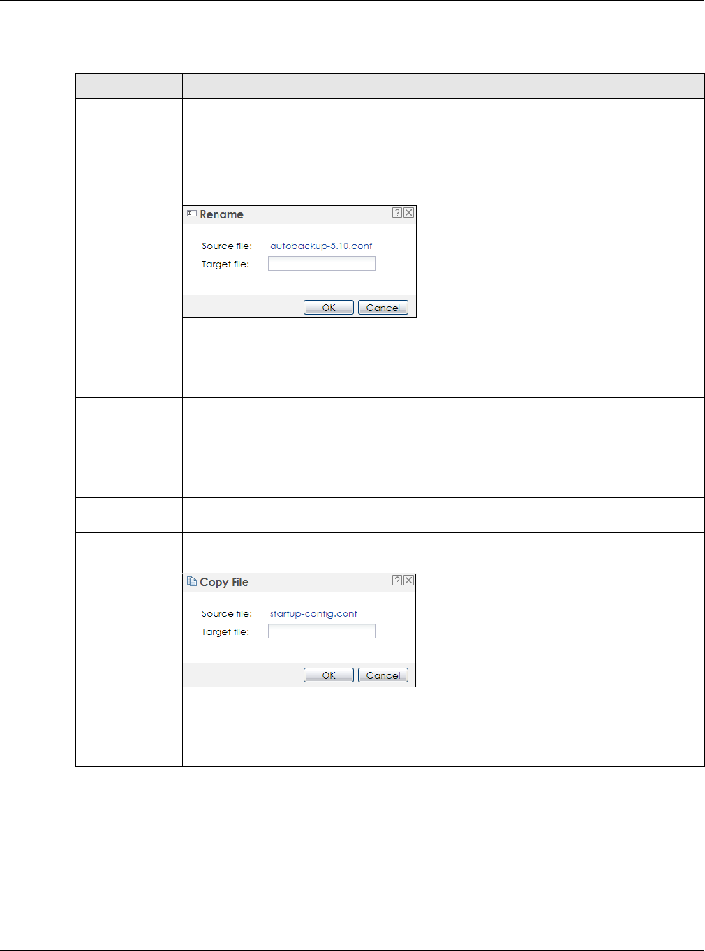
Chapter 16 File Manager
NWA / WAC Series User’s Guide
188
The following table describes the labels in this screen.
Table 86 Maintenance > File Manager > Configuration File
LABEL DESCRIPTION
Rename Use this button to change the label of a configuration file on the NWA/WAC. You can only
rename manually saved configuration files. You cannot rename the lastgood.conf, system-
default.conf and startup-config.conf files.
You cannot rename a configuration file to the name of another configuration file in the NWA/
WAC.
Click a configuration file’s row to select it and click Rename to open the Rename File screen.
Specify the new name for the configuration file. Use up to 25 characters (including a-zA-Z0-
9;‘~!@#$%^&()_+[]{}’,.=-).
Click OK to save the duplicate or click Cancel to close the screen without saving a duplicate of
the configuration file.
Remove Click a configuration file’s row to select it and click Remove to delete it from the NWA/WAC.
You can only delete manually saved configuration files. You cannot delete the system-
default.conf, startup-config.conf and lastgood.conf files.
A pop-up window asks you to confirm that you want to delete the configuration file. Click OK
to delete the configuration file or click Cancel to close the screen without deleting the
configuration file.
Download Click a configuration file’s row to select it and click Download to save the configuration to your
computer.
Copy Use this button to save a duplicate of a configuration file on the NWA/WAC.
Click a configuration file’s row to select it and click Copy to open the Copy File screen.
Specify a name for the duplicate configuration file. Use up to 25 characters (including a-zA-Z0-
9;‘~!@#$%^&()_+[]{}’,.=-).
Click OK to save the duplicate or click Cancel to close the screen without saving a duplicate of
the configuration file.
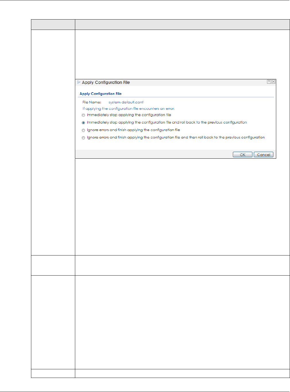
Chapter 16 File Manager
NWA / WAC Series User’s Guide
189
Apply Use this button to have the NWA/WAC use a specific configuration file.
Click a configuration file’s row to select it and click Apply to have the NWA/WAC use that
configuration file. The NWA/WAC does not have to restart in order to use a different
configuration file, although you will need to wait for a few minutes while the system
reconfigures.
The following screen gives you options for what the NWA/WAC is to do if it encounters an error
in the configuration file.
Immediately stop applying the configuration file - this is not recommended because it would
leave the rest of the configuration blank. If the interfaces were not configured before the first
error, the console port may be the only way to access the device.
Immediately stop applying the configuration file and roll back to the previous configuration -
this gets the NWA/WAC started with a fully valid configuration file as quickly as possible.
Ignore errors and finish applying the configuration file - this applies the valid parts of the
configuration file and generates error logs for all of the configuration file’s errors. This lets the
NWA/WAC apply most of your configuration and you can refer to the logs for what to fix.
Ignore errors and finish applying the configuration file and then roll back to the previous
configuration - this applies the valid parts of the configuration file, generates error logs for all of
the configuration file’s errors, and starts the NWA/WAC with a fully valid configuration file.
Click OK to have the NWA/WAC start applying the configuration file or click Cancel to close
the screen
#This column displays the number for each configuration file entry. This field is a sequential value,
and it is not associated with a specific address. The total number of configuration files that you
can save depends on the sizes of the configuration files and the available flash storage space.
File Name This column displays the label that identifies a configuration file.
You cannot delete the following configuration files or change their file names.
The system-default.conf file contains the NWA/WAC’s default settings. Select this file and click
Apply to reset all of the NWA/WAC settings to the factory defaults. This configuration file is
included when you upload a firmware package.
The startup-config.conf file is the configuration file that the NWA/WAC is currently using. If you
make and save changes during your management session, the changes are applied to this
configuration file. The NWA/WAC applies configuration changes made in the Web
Configurator to the configuration file when you click Apply or OK. It applies configuration
changes made via commands when you use the write command.
The lastgood.conf is the most recently used (valid) configuration file that was saved when the
device last restarted. If you upload and apply a configuration file with an error, you can apply
lastgood.conf to return to a valid configuration.
Size This column displays the size (in KB) of a configuration file.
Table 86 Maintenance > File Manager > Configuration File (continued)
LABEL DESCRIPTION

Chapter 16 File Manager
NWA / WAC Series User’s Guide
190
16.2.1 Example of Configuration File Download Using FTP
The following example gets a configuration file named startup-config.conf from the NWA/WAC and
saves it on the computer.
1Connect your computer to the NWA/WAC.
2The FTP server IP address of the NWA/WAC in standalone AP mode is 192.168.1.2, so set your computer
to use a static IP address from 192.168.1.3 ~192.168.1.254.
3Use an FTP client on your computer to connect to the NWA/WAC. For example, in the Windows
command prompt, type ftp 192.168.1.2. Keep the console session connected in order to see when
the firmware recovery finishes.
4Enter your user name when prompted.
5Enter your password as requested.
6Use “cd” to change to the directory that contains the files you want to download.
7Use “dir” or “ls” if you need to display a list of the files in the directory.
8Use "get” to download files. Transfer the configuration file on the NWA/WAC to your computer. Type get
followed by the name of the configuration file. This examples uses get startup-config.conf.
Last Modified This column displays the date and time that the individual configuration files were last changed
or saved.
Upload
Configuration File
The bottom part of the screen allows you to upload a new or previously saved configuration file
from your computer to your NWA/WAC
You cannot upload a configuration file named system-default.conf or lastgood.conf.
If you upload startup-config.conf, it will replace the current configuration and immediately
apply the new settings.
File Path Type in the location of the file you want to upload in this field or click Browse... to find it.
Browse... Click Browse... to find the .conf file you want to upload. The configuration file must use a
“.conf” filename extension. You will receive an error message if you try to upload a fie of a
different format. Remember that you must decompress compressed (.zip) files before you can
upload them.
Upload Click Upload to begin the upload process. This process may take up to two minutes.
Table 86 Maintenance > File Manager > Configuration File (continued)
LABEL DESCRIPTION

Chapter 16 File Manager
NWA / WAC Series User’s Guide
191
9Wait for the file transfer to complete.
10 Enter “quit” to exit the ftp prompt.
16.3 Firmware Package
Click Maintenance > File Manager > Firmware Package to open this screen. Use the Firmware Package
screen to check your current firmware version and upload firmware to the NWA/WAC.
Note: The Web Configurator is the recommended method for uploading firmware. You only
need to use the command line interface if you need to recover the firmware. See the
CLI Reference Guide for how to determine if you need to recover the firmware and
how to recover it.
Find the firmware package at www.zyxel.com in a file that (usually) uses a .bin extension.
The firmware update can take up to five minutes. Do not turn off or reset
the NWA/WAC while the firmware update is in progress!
C:\>ftp 192.168.1.2
Connected to 192.168.1.2.
220---------- Welcome to Pure-FTPd [privsep] [TLS] ----------
220-You are user number 1 of 5 allowed.
220-Local time is now 21:28. Server port: 21.
220-This is a private system - No anonymous login
220 You will be disconnected after 600 minutes of inactivity.
User (192.168.1.2:(none)): admin
331 User admin OK. Password required
Password:
230 OK. Current restricted directory is /
ftp> cd conf
250 OK. Current directory is /conf
ftp> ls
200 PORT command successful
150 Connecting to port 5001
lastgood.conf
startup-config.conf
system-default.conf
226 3 matches total
ftp: 57 bytes received in 0.33Seconds 0.17Kbytes/sec.
ftp> get startup-config.conf
200 PORT command successful
150 Connecting to port 5002
226-File successfully transferred
226 0.002 seconds (measured here), 1.66 Mbytes per second
ftp: 2928 bytes received in 0.02Seconds 183.00Kbytes/sec.
ftp>
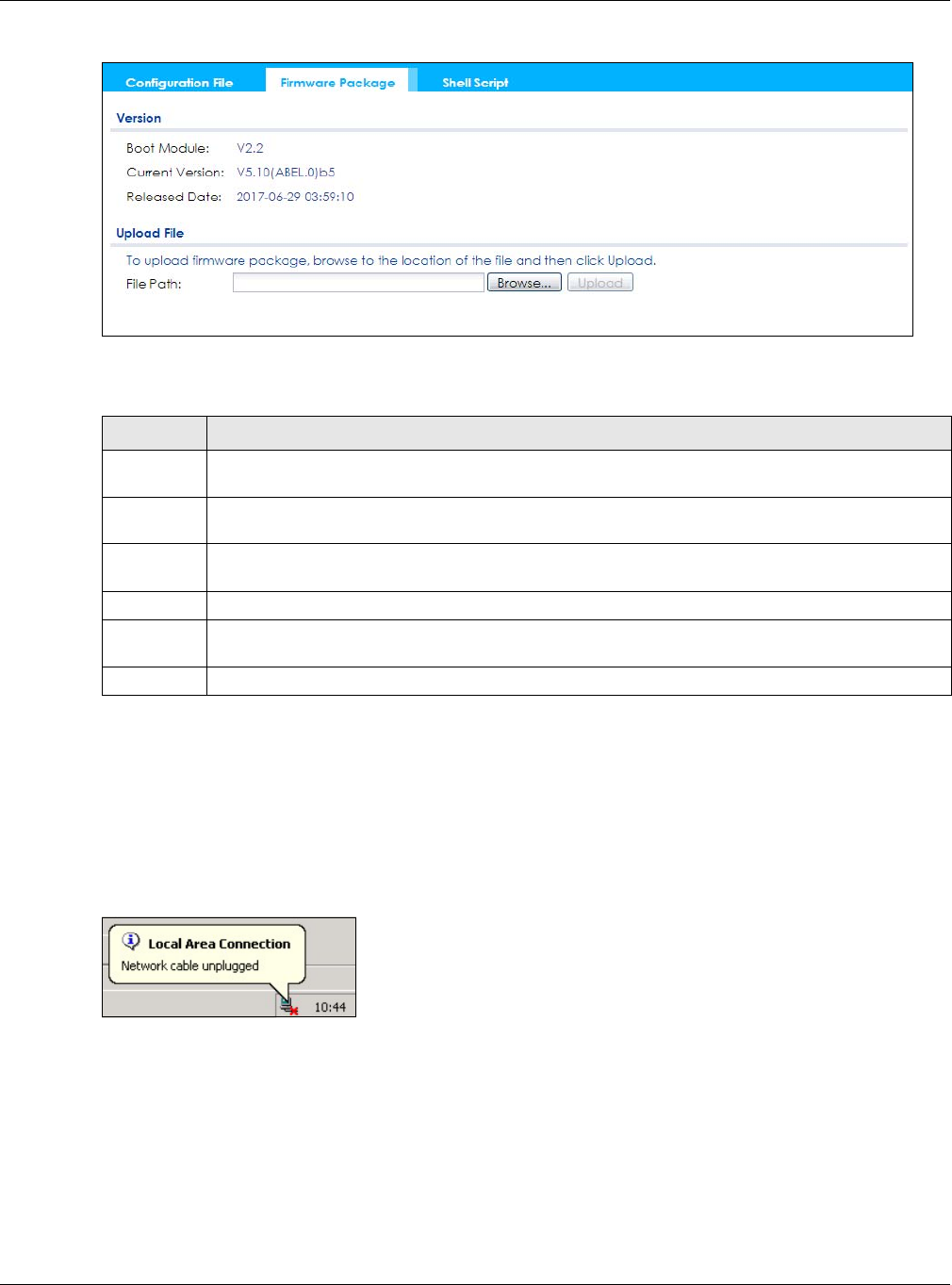
Chapter 16 File Manager
NWA / WAC Series User’s Guide
192
Figure 119 Maintenance > File Manager > Firmware Package
The following table describes the labels in this screen.
After you see the Firmware Upload in Process screen, wait two minutes before logging into the NWA/
WAC again.
Note: The NWA/WAC automatically reboots after a successful upload.
The NWA/WAC automatically restarts causing a temporary network disconnect. In some operating
systems, you may see the following icon on your desktop.
Figure 120 Network Temporarily Disconnected
After five minutes, log in again and check your new firmware version in the Dashboard screen.
16.3.1 Example of Firmware Upload Using FTP
This procedure requires the NWA/WAC’s firmware. Download the firmware package from
www.zyxel.com and unzip it. The firmware file uses a .bin extension, for example, "510ABFH0C0.bin". Do
the following after you have obtained the firmware file.
1Connect your computer to the NWA/WAC.
Table 87 Maintenance > File Manager > Firmware Package
LABEL DESCRIPTION
Boot
Module
This is the version of the boot module that is currently on the NWA/WAC.
Current
Version
This is the firmware version and the date created.
Released
Date
This is the date that the version of the firmware was created.
File Path Type in the location of the file you want to upload in this field or click Browse... to find it.
Browse... Click Browse... to find the .bin file you want to upload. Remember that you must decompress
compressed (.zip) files before you can upload them.
Upload Click Upload to begin the upload process. This process may take up to two minutes.

Chapter 16 File Manager
NWA / WAC Series User’s Guide
193
2The FTP server IP address of the NWA/WAC in standalone AP mode is 192.168.1.2, so set your computer
to use a static IP address from 192.168.1.3 ~192.168.1.254.
3Use an FTP client on your computer to connect to the NWA/WAC. For example, in the Windows
command prompt, type ftp 192.168.1.2. Keep the console session connected in order to see when
the firmware recovery finishes.
4Enter your user name when prompted.
5Enter your password as requested.
6Enter “hash” for FTP to print a `#' character for every 1024 bytes of data you upload so that you can
watch the file transfer progress.
7Enter “bin” to set the transfer mode to binary.
8Transfer the firmware file from your computer to the NWA/WAC. Type put followed by the path and
name of the firmware file. This examples uses put C:\ftproot\NWA/WAC_FW\510ABFH0C0.bin.
9Wait for the file transfer to complete.
10 Enter “quit” to exit the ftp prompt.
16.4 Shell Script
Use shell script files to have the NWA/WAC use commands that you specify. Use a text editor to create
the shell script files. They must use a “.zysh” filename extension.
Click Maintenance > File Manager > Shell Script to open this screen. Use the Shell Script screen to store,
name, download, upload and run shell script files. You can store multiple shell script files on the NWA/
WAC at the same time.
Note: You should include write commands in your scripts. If you do not use the write
command, the changes will be lost when the NWA/WAC restarts. You could use
multiple write commands in a long script.
C:\>ftp 192.168.1.2
Connected to 192.168.1.2.
220---------- Welcome to Pure-FTPd [privsep] [TLS] ----------
220-You are user number 1 of 5 allowed.
220-Local time is now 21:28. Server port: 21.
220-This is a private system - No anonymous login
220 You will be disconnected after 600 minutes of inactivity.
User (192.168.1.2:(none)): admin
331 User admin OK. Password required
Password:
230 OK. Current restricted directory is /
ftp> hash
Hash mark printing On ftp: (2048 bytes/hash mark) .
ftp> bin
200 TYPE is now 8-bit binary
ftp> put C:\ftproot\NWA/WAC_FW\510ABFH0C0.bin
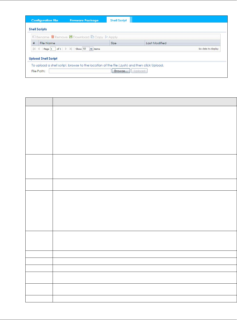
Chapter 16 File Manager
NWA / WAC Series User’s Guide
194
Figure 121 Maintenance > File Manager > Shell Script
Each field is described in the following table.
Table 88 Maintenance > File Manager > Shell Script
LABEL DESCRIPTION
Rename Use this button to change the label of a shell script file on the NWA/WAC.
You cannot rename a shell script to the name of another shell script in the NWA/WAC.
Click a shell script’s row to select it and click Rename to open the Rename File screen.
Specify the new name for the shell script file. Use up to 25 characters (including a-zA-Z0-
9;‘~!@#$%^&()_+[]{}’,.=-).
Click OK to save the duplicate or click Cancel to close the screen without saving a duplicate of the
configuration file.
Remove Click a shell script file’s row to select it and click Delete to delete the shell script file from the NWA/
WAC.
A pop-up window asks you to confirm that you want to delete the shell script file. Click OK to delete
the shell script file or click Cancel to close the screen without deleting the shell script file.
Download Click a shell script file’s row to select it and click Download to save the configuration to your
computer.
Copy Use this button to save a duplicate of a shell script file on the NWA/WAC.
Click a shell script file’s row to select it and click Copy to open the Copy File screen.
Specify a name for the duplicate file. Use up to 25 characters (including a-zA-Z0-
9;‘~!@#$%^&()_+[]{}’,.=-).
Click OK to save the duplicate or click Cancel to close the screen without saving a duplicate of the
configuration file.
Apply Use this button to have the NWA/WAC use a specific shell script file.
Click a shell script file’s row to select it and click Apply to have the NWA/WAC use that shell script
file. You may need to wait awhile for the NWA/WAC to finish applying the commands.
#This column displays the number for each shell script file entry.
File Name This column displays the label that identifies a shell script file.
Size This column displays the size (in KB) of a shell script file.
Last
Modified
This column displays the date and time that the individual shell script files were last changed or
saved.
Upload Shell
Script
The bottom part of the screen allows you to upload a new or previously saved shell script file from
your computer to your NWA/WAC.
File Path Type in the location of the file you want to upload in this field or click Browse... to find it.

Chapter 16 File Manager
NWA / WAC Series User’s Guide
195
Browse... Click Browse... to find the .zysh file you want to upload.
Upload Click Upload to begin the upload process. This process may take up to several minutes.
Table 88 Maintenance > File Manager > Shell Script (continued)
LABEL DESCRIPTION
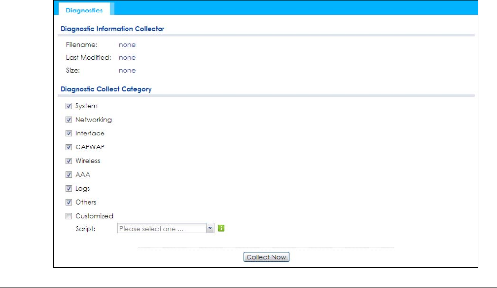
NWA / WAC Series User’s Guide
196
CHAPTER 17
Diagnostics
17.1 Overview
Use the diagnostics screen for troubleshooting.
17.1.1 What You Can Do in this Chapter
• The Diagnostics screen (Section 17.2 on page 196) generates a file containing the NWA/WAC’s
configuration and diagnostic information if you need to provide it to customer support during
troubleshooting.
17.2 Diagnostics
This screen provides an easy way for you to generate a file containing the NWA/WAC’s configuration
and diagnostic information. You may need to generate this file and send it to customer support during
troubleshooting.
Click Maintenance > Diagnostics to open the Diagnostic screen.
Figure 122 Maintenance > Diagnostics

Chapter 17 Diagnostics
NWA / WAC Series User’s Guide
197
The following table describes the labels in this screen.
Table 89 Maintenance > Diagnostics
LABEL DESCRIPTION
Filename This is the name of the most recently created diagnostic file.
Last modified This is the date and time that the last diagnostic file was created. The format is yyyy-mm-dd
hh:mm:ss.
Size This is the size of the most recently created diagnostic file.
Diagnostic Collect
Category
This field displays each category of settings. Select which categories you want the NWA/
WAC to include in the diagnostic file.
Customized Select this option to obtain the diagnostic information for configuration which is not
included in a pre-defined category.
Script If you select the Customized option, select a shell script file from the drop-down list. You can
upload a new shell script file using the Maintenance > File Manager > Shell Script screen.
Collect Now Click this to have the NWA/WAC create a new diagnostic file.
Download Click this to save the most recent diagnostic file to a computer.
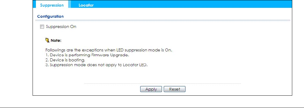
NWA / WAC Series User’s Guide
198
CHAPTER 18
LEDs
18.1 Overview
The LEDs of your NWA/WAC can be controlled such that they stay lit (ON) or OFF after the NWA/WAC is
ready. There are two features that control the LEDs of your NWA/WAC - Locator and Suppression.
18.1.1 What You Can Do in this Chapter
• The Suppression screen (Section 18.2 on page 198)) allows you to set how you want the LEDs to
behave after the device is ready.
• The Locator screen (Section 18.3 on page 199) allows users to see the actual location of the NWA/
WAC between several devices in the network.
18.2 Suppression Screen
The LED Suppression feature allows you to control how the LEDs of your NWA/WAC behave after it’s
ready. The default LED suppression setting of your AP is different depending on your NWA/WAC model.
You can go to the Maintenance > LEDs > Suppression screen to see the default LED behavior and
change the LED suppression setting. After you make changes in the suppression screen, it will be stored
as the default when the NWA/WAC is restarted. See (Section 1.6 on page 25) for information on default
values for different models.
Note: When the NWA/WAC is booting or performing firmware upgrade, the LEDs will lit regardless of
the setting in LED suppression.
To access this screen, click Maintenance > LEDs > Suppression.
Figure 123 Maintenance > LEDs > Suppression
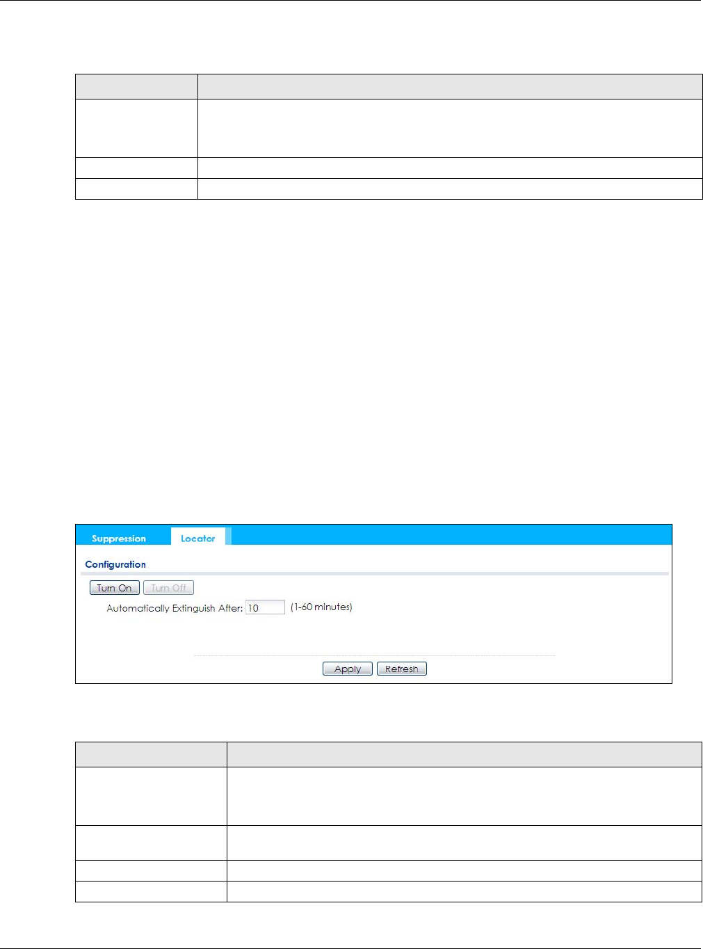
Chapter 18 LEDs
NWA / WAC Series User’s Guide
199
The following table describes fields in the above screen.
18.3 Locator Screen
The Locator feature identifies the location of your WAC among several devices in the network. You can
run this feature and set a timer in this screen.
To run the locator feature, enter a number of minutes and click Turn On button to have the WAC find its
location. The Locator LED will start to blink for the number of minutes set in the Locator screen. The
default setting is 10 minutes. While the locator is running, the turn on button will gray out and return after
it’s finished. If you make changes to the time default setting, it will be stored as the default when the
WAC restarts.
Note: The Locator feature is not affected by the Suppression setting.
To access this screen, click Maintenance > LEDs > Locator.
Figure 124 Maintenance > LEDs > Locator
The following table describes fields in the above screen.
Table 90 Maintenance > LED > Suppression
LABEL DESCRIPTION
Suppression On If the Suppression On check box is checked, the LEDs of your NWA/WAC will turn off after it’s
ready.
If the check box is unchecked, the LEDs will stay lit after the NWA/WAC is ready.
Apply Click Apply to save your changes back to the NWA/WAC.
Reset Click Reset to return the screen to its last-saved settings.
Table 91 Maintenance > LED > Locator
LABEL DESCRIPTION
Turn On
Turn Off
Click Turn On button to activate the locator. The Locator function will show the actual
location of the WAC between several devices in the network.
Otherwise, click Turn Off to disable the locator feature.
Automatically Extinguish
After
Enter a time interval between 1 and 60 minutes to stop the locator LED from blinking.
Default is 10 minutes.
Apply Click Apply to save changes in this screen.
Refresh Click Refresh to update the information in this screen.
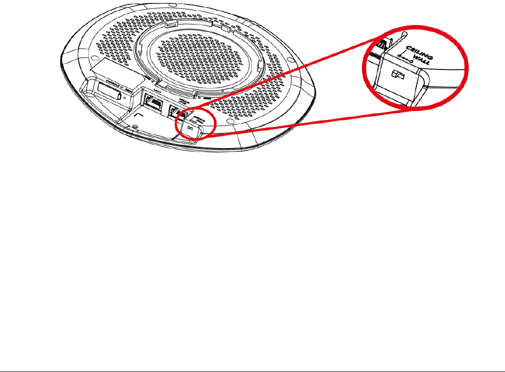
NWA / WAC Series User’s Guide
200
CHAPTER 19
Antenna Switch
19.1 Overview
Use this screen to adjust coverage depending on the orientation of the antenna.
19.1.1 What You Need To Know
Positioning the antennas properly increases the range and coverage area of a wireless LAN.
On the NWA/WAC that comes with internal antennas and also has an antenna switch, you can adjust
coverage depending on the orientation of the antenna for the NWA/WAC radios using the web
configurator, the command line interface (CLI) or a physical switch. Check Table 1 on page 13 and
Table 3 on page 15 to see if your NWA/WAC has an antenna switch.
Figure 125 WAC6103D-I Physical Antenna Switch
Note: With the physical antenna switch, you apply the same antenna orientation settings to
both radios. You can set the radios to have different settings while using the web
configurator or the command line interface.
Note: The antenna switch in the web configurator has priority over the physical antenna
switch after you Enable Software Control in the Maintenance > Antenna screen. By
default, software control is disabled.
19.2 Antenna Switch Screen
To access this screen, click Maintenance > Antenna.
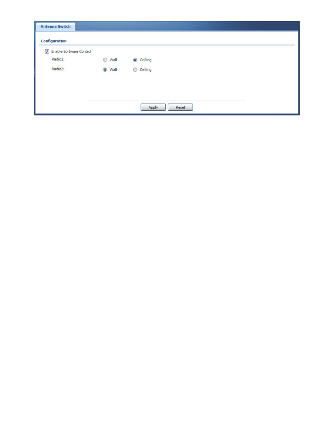
Chapter 19 Antenna Switch
NWA / WAC Series User’s Guide
201
Figure 126 Maintenance > Antenna > Antenna Switch
Select the Enable Software Control option to use the Web configurator to adjust coverage depending
on each radio’s antenna orientation for better coverage. Select Wall if you mount the NWA/WAC to a
wall. Select Ceiling if the NWA/WAC is mounted on a ceiling. You can switch from Wall to Ceiling if there
are still wireless dead zones, and vice versa.
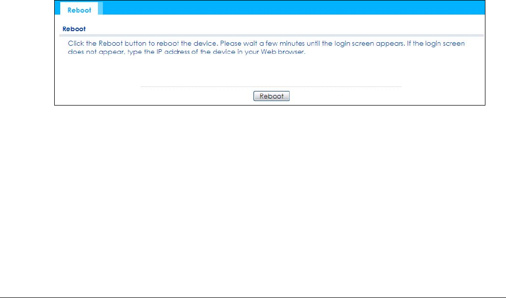
NWA / WAC Series User’s Guide
202
CHAPTER 20
Reboot
20.1 Overview
Use this screen to restart the device.
20.1.1 What You Need To Know
If you applied changes in the Web configurator, these were saved automatically and do not change
when you reboot. If you made changes in the CLI, however, you have to use the write command to
save the configuration before you reboot. Otherwise, the changes are lost when you reboot.
Reboot is different to reset; reset returns the device to its default configuration.
20.2 Reboot
This screen allows remote users can restart the device. To access this screen, click Maintenance >
Reboot.
Figure 127 Maintenance > Reboot
Click the Reboot button to restart the NWA/WAC. Wait a few minutes until the login screen appears. If
the login screen does not appear, type the IP address of the device in your Web browser.
You can also use the CLI command reboot to restart the NWA/WAC.
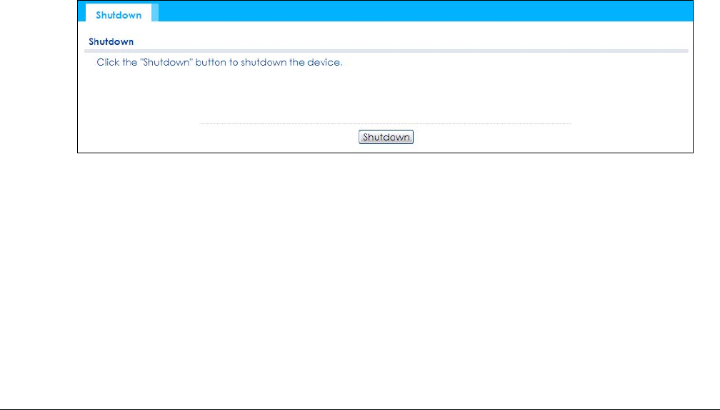
NWA / WAC Series User’s Guide
203
CHAPTER 21
Shutdown
21.1 Overview
Use this screen to shut down the device.
Always use Maintenance > Shutdown > Shutdown or the shutdown
command before you turn off the NWA/WAC or remove the power. Not
doing so can cause the firmware to become corrupt.
21.1.1 What You Need To Know
Shutdown writes all cached data to the local storage and stops the system processes. Shutdown is
different to reset; reset returns the device to its default configuration.
21.2 Shutdown
To access this screen, click Maintenance > Shutdown.
Figure 128 Maintenance > Shutdown
Click the Shutdown button to shut down the NWA/WAC. Wait for the device to shut down before you
manually turn off or remove the power. It does not turn off the power.
You can also use the CLI command shutdown to shut down the NWA/WAC.

NWA / WAC Series User’s Guide
204
CHAPTER 22
Troubleshooting
22.1 Overview
This chapter offers some suggestions to solve problems you might encounter. The potential problems are
divided into the following categories.
•Power, Hardware Connections, and LED
•NWA/WAC Access and Login
•Internet Access
•Wireless Connections
•Resetting the NWA/WAC
22.2 Power, Hardware Connections, and LED
The NWA/WAC does not turn on. The LED is not on.
1Make sure you are using the power adaptor included with the NWA/WAC or a PoE power injector/
switch.
2Make sure the power adaptor or PoE power injector/switch is connected to the NWA/WAC and
plugged in to an appropriate power source. Make sure the power source is turned on.
3Disconnect and re-connect the power adaptor or PoE power injector/switch.
4Inspect your cables for damage. Contact the vendor to replace any damaged cables.
5If none of these steps work, you may have faulty hardware and should contact your NWA/WAC vendor.
The LED does not behave as expected.
1Make sure you understand the normal behavior of the LED. See Section 1.6 on page 25.
2Check the hardware connections. See the Quick Start Guide.
3Inspect your cables for damage. Contact the vendor to replace any damaged cables.

Chapter 22 Troubleshooting
NWA / WAC Series User’s Guide
205
4Disconnect and re-connect the power adaptor or PoE power injector to the NWA/WAC.
5If the problem continues, contact the vendor.
22.3 NWA/WAC Access and Login
I forgot the IP address for the NWA/WAC.
1The default IP address (in standalone AP mode) is 192.168.1.2.
2If you changed the IP address and have forgotten it, you have to reset the device to its factory defaults.
See Section 22.6 on page 212.
3If your NWA/WAC is a DHCP client, you can find your IP address from the DHCP server. This information is
only available from the DHCP server which allocates IP addresses on your network. Find this information
directly from the DHCP server or contact your system administrator for more information.
I cannot see or access the Login screen in the web configurator.
1Make sure you are using the correct IP address.
• The default IP address (in standalone AP mode) is 192.168.1.2.
• If you changed the IP address, use the new IP address.
• If you changed the IP address and have forgotten it, see the troubleshooting suggestions for I
forgot the IP address for the NWA/WAC.
2Check the hardware connections, and make sure the LED is behaving as expected. See the Quick Start
Guide and Section 1.6 on page 25.
3Make sure your Internet browser does not block pop-up windows and has JavaScripts and Java
enabled.
4Make sure your computer is in the same subnet as the NWA/WAC. (If you know that there are routers
between your computer and the NWA/WAC, skip this step.)
• If there is a DHCP server on your network, make sure your computer is using a dynamic IP address.
• If there is no DHCP server on your network, make sure your computer’s IP address is in the same
subnet as the NWA/WAC.
5Reset the device to its factory defaults, and try to access the NWA/WAC with the default IP address. See
Section 22.6 on page 212.
6If the problem continues, contact the network administrator or vendor, or try one of the advanced
suggestions.
Advanced Suggestions

Chapter 22 Troubleshooting
NWA / WAC Series User’s Guide
206
• Try to access the NWA/WAC using another service, such as Telnet. If you can access the NWA/WAC,
check the remote management settings to find out why the NWA/WAC does not respond to HTTP.
• If your computer is connected wirelessly, use a computer that is connected to a LAN/ETHERNET port.
I forgot the password.
1The default password is 1234.
2If this does not work, you have to reset the device to its factory defaults. See Section 22.6 on page 212.
I can see the Login screen, but I cannot log in to the NWA/WAC.
1Make sure you have entered the user name and password correctly. The default password is 1234. This
fields are case-sensitive, so make sure [Caps Lock] is not on.
2You cannot log in to the web configurator while someone is using Telnet to access the NWA/WAC. Log
out of the NWA/WAC in the other session, or ask the person who is logged in to log out.
3Disconnect and re-connect the power adaptor or PoE power injector to the NWA/WAC.
4If this does not work, you have to reset the device to its factory defaults. See Section 22.6 on page 212.
I cannot use FTP to upload / download the configuration file. / I cannot use FTP to upload new
firmware.
See the troubleshooting suggestions for I cannot see or access the Login screen in the web configurator.
Ignore the suggestions about your browser.
22.4 Internet Access
I cannot access the Internet.
1Check the hardware connections, and make sure the LED is behaving as expected. See the Quick Start
Guide and Section 22.2 on page 204.
2Make sure the NWA/WAC is connected to a broadband modem or router with Internet access and your
computer is set to obtain an dynamic IP address.

Chapter 22 Troubleshooting
NWA / WAC Series User’s Guide
207
3If you are trying to access the Internet wirelessly, make sure the wireless settings on the wireless client are
the same as the settings on the NWA/WAC.
4Disconnect all the cables from your device, and follow the directions in the Quick Start Guide again.
5If the problem continues, contact your ISP.
I cannot access the Internet anymore. I had access to the Internet (with the NWA/WAC), but my
Internet connection is not available anymore.
1Check the hardware connections, and make sure the LED is behaving as expected. See the Quick Start
Guide and Section 1.6 on page 25.
2Reboot the NWA/WAC.
3If the problem continues, contact your ISP.
The Internet connection is slow or intermittent.
1There might be a lot of traffic on the network. Look at the LED, and check Section 1.6 on page 25. If the
NWA/WAC is sending or receiving a lot of information, try closing some programs that use the Internet,
especially peer-to-peer applications.
2Check the signal strength. If the signal is weak, try moving the NWA/WAC closer to the NWA/WAC (if
possible), and look around to see if there are any devices that might be interfering with the wireless
network (microwaves, other wireless networks, and so on).
3Reboot the NWA/WAC.
4If the problem continues, contact the network administrator or vendor, or try one of the advanced
suggestions.
Advanced Suggestions
Check the settings for QoS. If it is disabled, you might consider activating it. If it is enabled, you
might consider raising or lowering the priority for some applications.
22.5 Wireless Connections
I cannot access the NWA/WAC or ping any computer from the WLAN.
1Make sure the wireless LAN (wireless radio) is enabled on the NWA/WAC.

Chapter 22 Troubleshooting
NWA / WAC Series User’s Guide
208
2Make sure the radio or at least one of the NWA/WAC’s radios is operating in AP mode.
3Make sure the wireless adapter (installed on your computer) is working properly.
4Make sure the wireless adapter (installed on your computer) is IEEE 802.11 compatible and supports the
same wireless standard as the NWA/WAC’s active radio.
5Make sure your computer (with a wireless adapter installed) is within the transmission range of the NWA/
WAC.
6Check that both the NWA/WAC and your computer are using the same wireless and wireless security
settings.
Hackers have accessed my WEP-encrypted wireless LAN.
WEP is extremely insecure. Its encryption can be broken by an attacker, using widely-available software.
It is strongly recommended that you use a more effective security mechanism. Use the strongest security
mechanism that all the wireless devices in your network support. WPA2 or WPA2-PSK is recommended.
The wireless security is not following the re-authentication timer setting I specified.
If a RADIUS server authenticates wireless stations, the re-authentication timer on the RADIUS server has
priority. Change the RADIUS server’s configuration if you need to use a different re-authentication timer
setting.
I cannot get a certificate to import into the NWA/WAC.
1For My Certificates, you can import a certificate that matches a corresponding certification request that
was generated by the NWA/WAC. You can also import a certificate in PKCS#12 format, including the
certificate’s public and private keys.
2You must remove any spaces from the certificate’s filename before you can import the certificate.
3Any certificate that you want to import has to be in one of these file formats:
• Binary X.509: This is an ITU-T recommendation that defines the formats for X.509 certificates.
• PEM (Base-64) encoded X.509: This Privacy Enhanced Mail format uses lowercase letters, uppercase
letters and numerals to convert a binary X.509 certificate into a printable form.
• Binary PKCS#7: This is a standard that defines the general syntax for data (including digital signatures)
that may be encrypted. A PKCS #7 file is used to transfer a public key certificate. The private key is not
included. The NWA/WAC currently allows the importation of a PKS#7 file that contains a single
certificate.
• PEM (Base-64) encoded PKCS#7: This Privacy Enhanced Mail (PEM) format uses lowercase letters,
uppercase letters and numerals to convert a binary PKCS#7 certificate into a printable form.

Chapter 22 Troubleshooting
NWA / WAC Series User’s Guide
209
• Binary PKCS#12: This is a format for transferring public key and private key certificates.The private key
in a PKCS #12 file is within a password-encrypted envelope. The file’s password is not connected to
your certificate’s public or private passwords. Exporting a PKCS #12 file creates this and you must
provide it to decrypt the contents when you import the file into the NWA/WAC.
Note: Be careful not to convert a binary file to text during the transfer process. It is easy for this
to occur since many programs use text files by default.
I can only see newer logs. Older logs are missing.
When a log reaches the maximum number of log messages, new log messages automatically overwrite
existing log messages, starting with the oldest existing log message first.
The commands in my configuration file or shell script are not working properly.
• In a configuration file or shell script, use “#” or “!” as the first character of a command line to have the
NWA/WAC treat the line as a comment.
• Your configuration files or shell scripts can use “exit” or a command line consisting of a single “!” to
have the NWA/WAC exit sub command mode.
•Include write commands in your scripts. Otherwise the changes will be lost when the NWA/WAC
restarts. You could use multiple write commands in a long script.
Note: “exit” or “!'” must follow sub commands if it is to make the NWA/WAC exit sub
command mode.
I cannot get the firmware uploaded using the commands.
The Web Configurator is the recommended method for uploading firmware. You only need to use the
command line interface if you need to recover the firmware. See the CLI Reference Guide for how to
determine if you need to recover the firmware and how to recover it.
Wireless clients are not being load balanced among my APs.
• Make sure that all the APs used by the wireless clients in question share the same SSID, security, and
radio settings.
• Make sure that all the APs are in the same broadcast domain.
• Make sure that the wireless clients are in range of the other APs; if they are only in range of a single
AP, then load balancing may not be as effective.
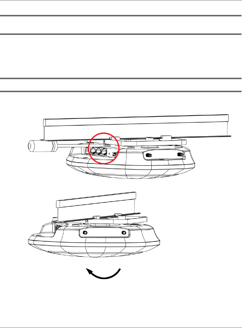
Chapter 22 Troubleshooting
NWA / WAC Series User’s Guide
210
In the Monitor > Wireless > AP Information > Radio List screen, there is no load balancing indicator
associated with any APs assigned to the load balancing task.
• Check to be sure that the AP profile which contains the load balancing settings is correctly assigned
to the APs in question.
• The load balancing task may have been terminated because further load balancing on the APs in
question is no longer required.
How do I remove the WAC6500 series indoor AP from its mounting bracket?
• Find the down arrow close to the Ethernet ports, then use a thin flat tool (for example, a flat screw
driver) to lift up a clip beneath the down arrow.
• Turn the WAC6500 series indoor AP counter-clockwise.
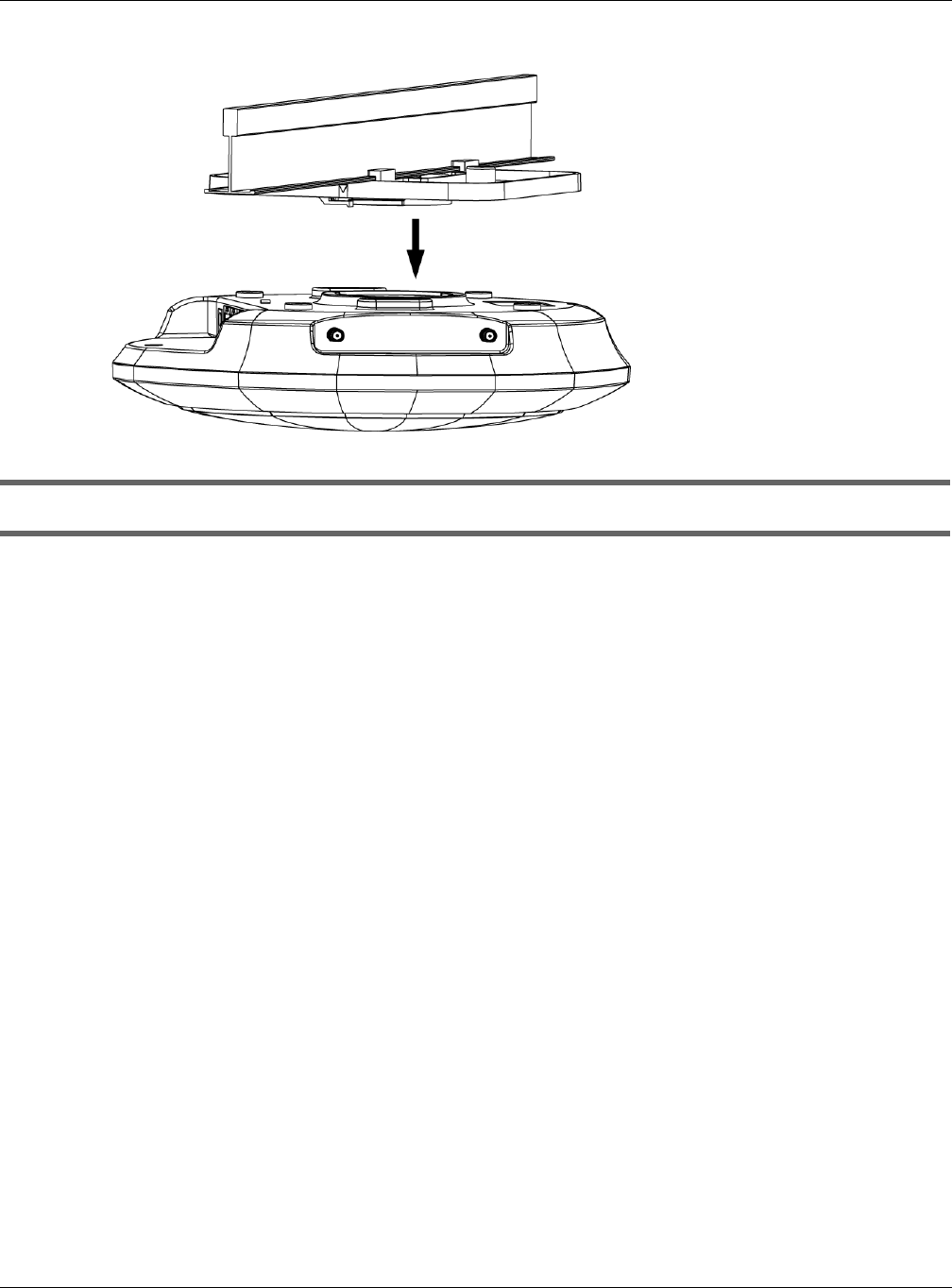
Chapter 22 Troubleshooting
NWA / WAC Series User’s Guide
211
• Detach the WAC6500 series indoor AP from the mounting bracket.
How do I remove the NWA1123-AC PRO and WAC6103D-I indoor AP from its mounting bracket?
• Find the down arrow close to the Ethernet ports, then use a thin flat tool (for example, a flat screw
driver) to lift up a clip beneath 5GHz LED.
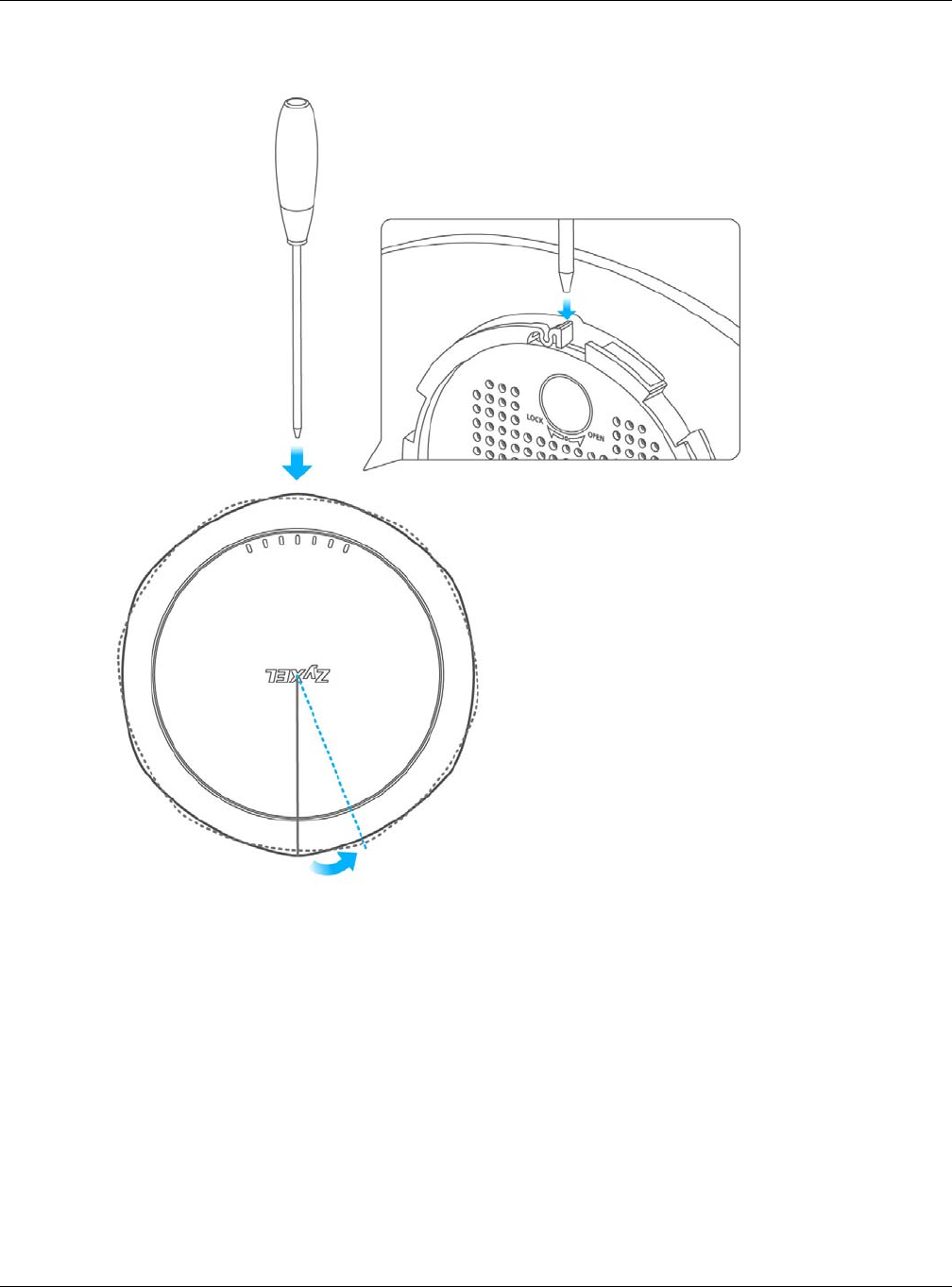
Chapter 22 Troubleshooting
NWA / WAC Series User’s Guide
212
• Turn the NWA1123-AC PRO or WAC6103D-I indoor AP counter-clockwise to detach it from the
mounting bracket.
22.6 Resetting the NWA/WAC
If you cannot access the NWA/WAC by any method, try restarting it by turning the power off and then
on again. If you still cannot access the NWA/WAC by any method or you forget the administrator
password(s), you can reset the NWA/WAC to its factory-default settings. Any configuration files or shell
scripts that you saved on the NWA/WAC should still be available afterwards.
Use the following procedure to reset the NWA/WAC to its factory-default settings. This overwrites the
settings in the startup-config.conf file with the settings in the system-default.conf file.
Note: This procedure removes the current configuration.

Chapter 22 Troubleshooting
NWA / WAC Series User’s Guide
213
1Make sure the Power LED is on and not blinking.
2Press the RESET button and hold it until the Power LED begins to blink. (This usually takes about ten
seconds.)
3Release the RESET button, and wait for the NWA/WAC to restart.
You should be able to access the NWA/WAC using the default settings.
22.7 Getting More Troubleshooting Help
Search for support information for your model at www.zyxel.com for more troubleshooting suggestions.

NWA / WAC Series User’s Guide
214
APPENDIX A
Importing Certificates
This appendix shows you how to import public key certificates into your web browser.
Public key certificates are used by web browsers to ensure that a secure web site is legitimate. When a
certificate authority such as VeriSign, Comodo, or Network Solutions, to name a few, receives a
certificate request from a website operator, they confirm that the web domain and contact information
in the request match those on public record with a domain name registrar. If they match, then the
certificate is issued to the website operator, who then places it on the site to be issued to all visiting web
browsers to let them know that the site is legitimate.
Many Zyxel products, such as the NWA/WAC, issue their own public key certificates. These can be used
by web browsers on a LAN or WAN to verify that they are in fact connecting to the legitimate device
and not one masquerading as it. However, because the certificates were not issued by one of the
several organizations officially recognized by the most common web browsers, you will need to import
the Zyxel-created certificate into your web browser and flag that certificate as a trusted authority.
Note: You can see if you are browsing on a secure website if the URL in your web browser’s
address bar begins with https:// or there is a sealed padlock icon ( ) somewhere
in the main browser window (not all browsers show the padlock in the same location).
Internet Explorer
The following example uses Microsoft Internet Explorer 7 on Windows XP Professional; however, they can
also apply to Internet Explorer on Windows Vista.
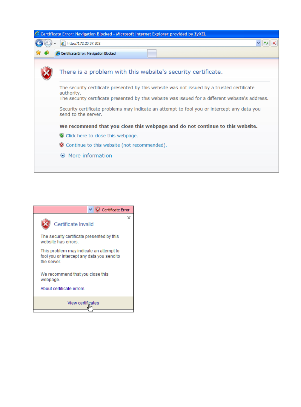
Appendix A Importing Certificates
NWA / WAC Series User’s Guide
215
1If your device’s Web Configurator is set to use SSL certification, then the first time you browse to it you are
presented with a certification error.
2Click Continue to this website (not recommended).
3In the Address Bar, click Certificate Error > View certificates.
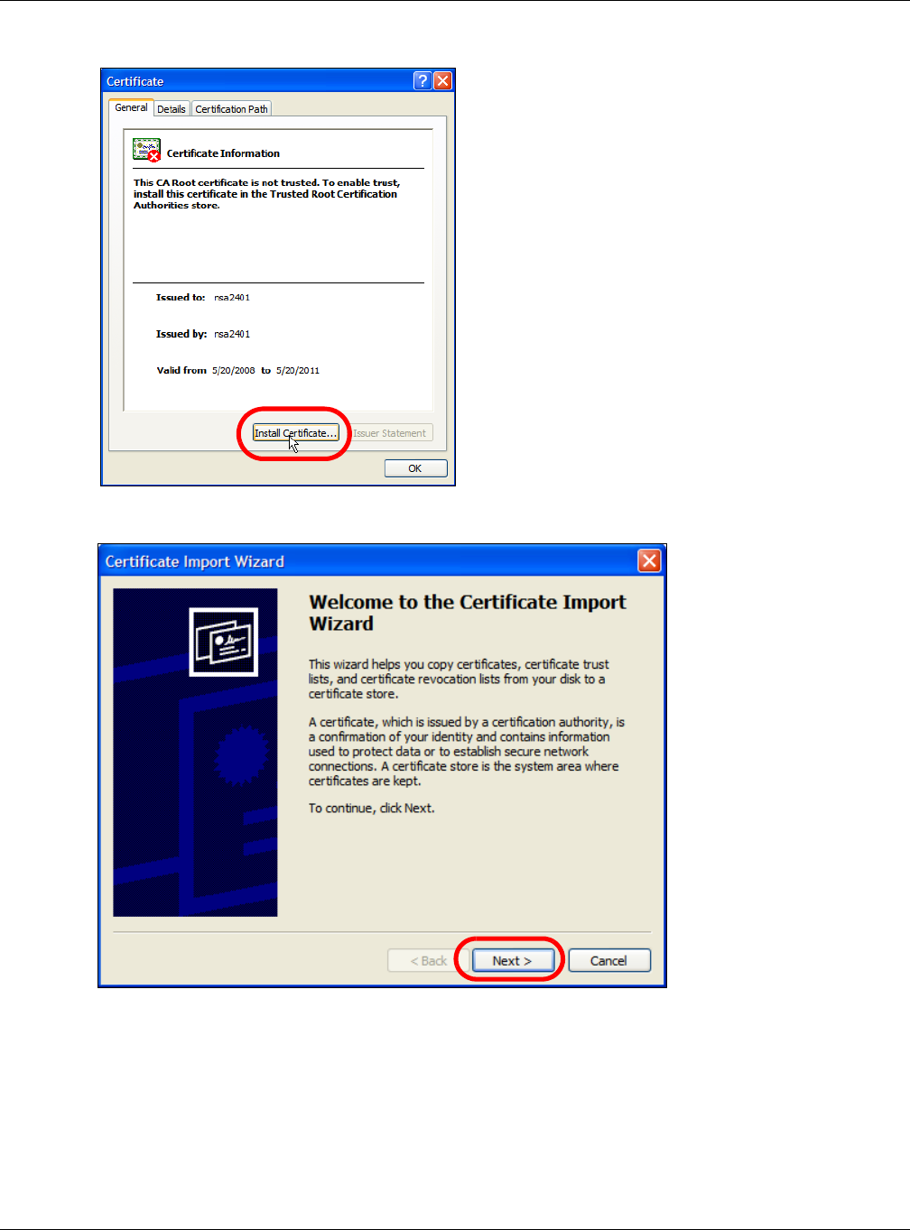
Appendix A Importing Certificates
NWA / WAC Series User’s Guide
216
4In the Certificate dialog box, click Install Certificate.
5In the Certificate Import Wizard, click Next.
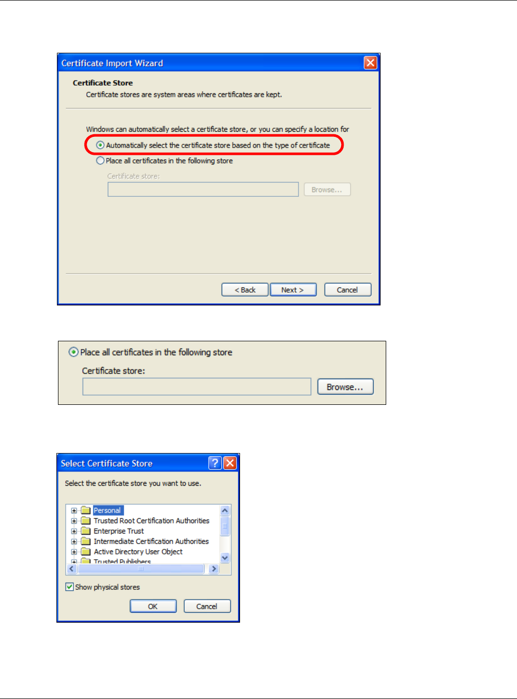
Appendix A Importing Certificates
NWA / WAC Series User’s Guide
217
6If you want Internet Explorer to Automatically select certificate store based on the type of certificate,
click Next again and then go to step 9.
7Otherwise, select Place all certificates in the following store and then click Browse.
8In the Select Certificate Store dialog box, choose a location in which to save the certificate and then
click OK.
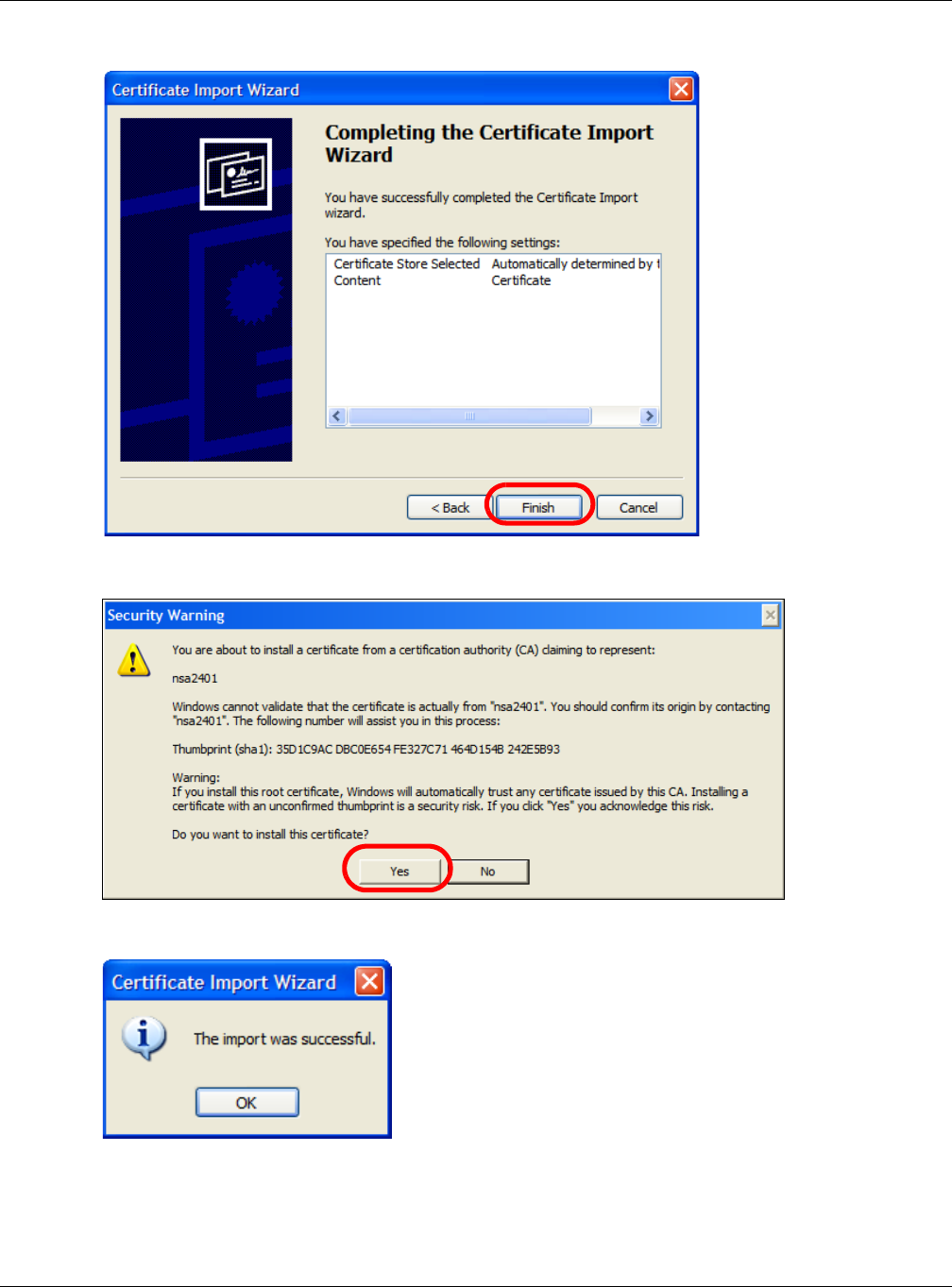
Appendix A Importing Certificates
NWA / WAC Series User’s Guide
218
9In the Completing the Certificate Import Wizard screen, click Finish.
10 If you are presented with another Security Warning, click Yes.
11 Finally, click OK when presented with the successful certificate installation message.
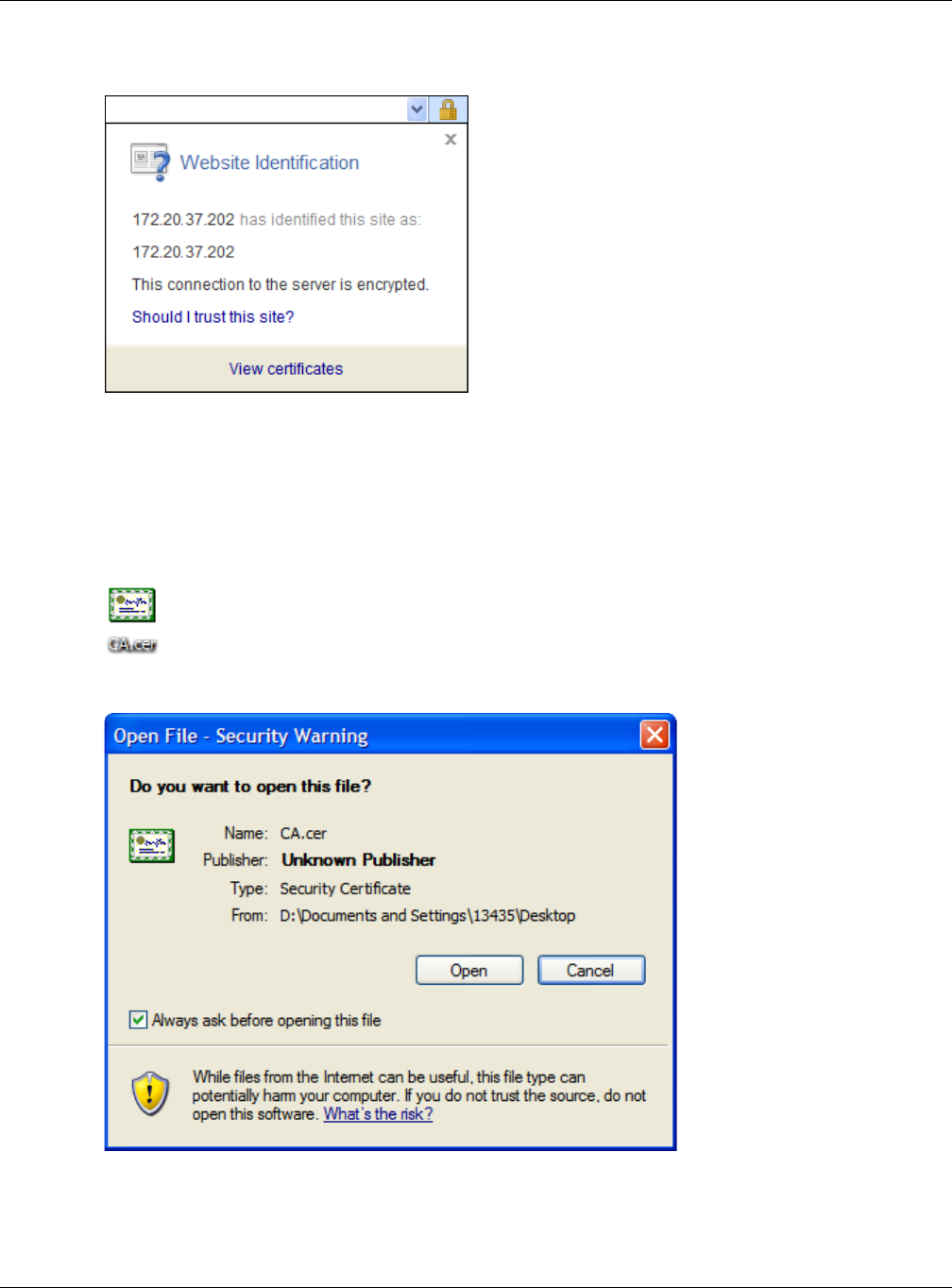
Appendix A Importing Certificates
NWA / WAC Series User’s Guide
219
12 The next time you start Internet Explorer and go to a Zyxel Web Configurator page, a sealed padlock
icon appears in the address bar. Click it to view the page’s Website Identification information.
Installing a Stand-Alone Certificate File in Internet Explorer
Rather than browsing to a Zyxel Web Configurator and installing a public key certificate when
prompted, you can install a stand-alone certificate file if one has been issued to you.
1Double-click the public key certificate file.
2In the security warning dialog box, click Open.
3Refer to steps 4-12 in the Internet Explorer procedure beginning on page 214 to complete the
installation process.
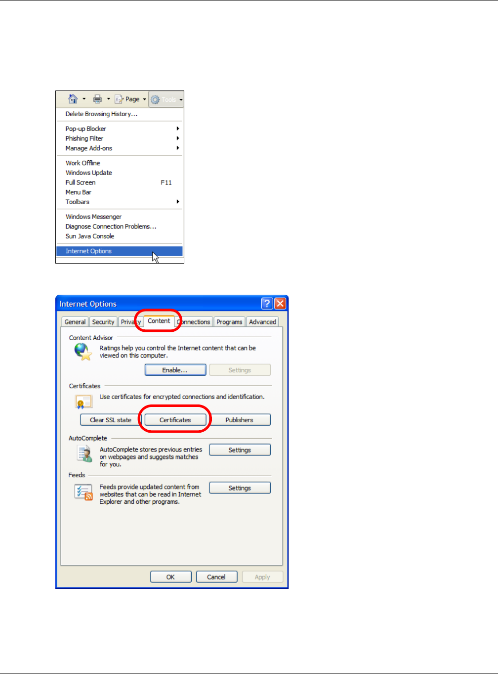
Appendix A Importing Certificates
NWA / WAC Series User’s Guide
220
Removing a Certificate in Internet Explorer
This section shows you how to remove a public key certificate in Internet Explorer 7 on Windows XP.
1Open Internet Explorer and click Tools > Internet Options.
2In the Internet Options dialog box, click Content > Certificates.
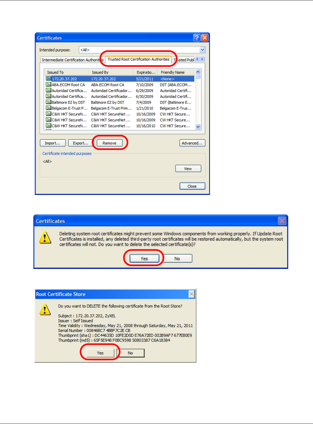
Appendix A Importing Certificates
NWA / WAC Series User’s Guide
221
3In the Certificates dialog box, click the Trusted Root Certificates Authorities tab, select the certificate
that you want to delete, and then click Remove.
4In the Certificates confirmation, click Yes.
5In the Root Certificate Store dialog box, click Yes.
6The next time you go to the web site that issued the public key certificate you just removed, a
certification error appears.
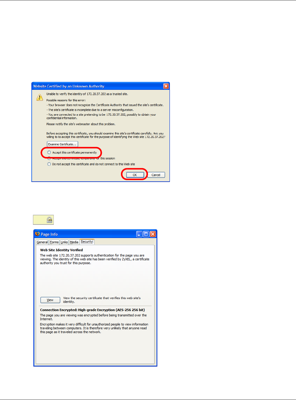
Appendix A Importing Certificates
NWA / WAC Series User’s Guide
222
Firefox
The following example uses Mozilla Firefox 2 on Windows XP Professional; however, the screens can also
apply to Firefox 2 on all platforms.
1If your device’s Web Configurator is set to use SSL certification, then the first time you browse to it you are
presented with a certification error.
2Select Accept this certificate permanently and click OK.
3The certificate is stored and you can now connect securely to the Web Configurator. A sealed padlock
appears in the address bar, which you can click to open the Page Info > Security window to view the
web page’s security information.
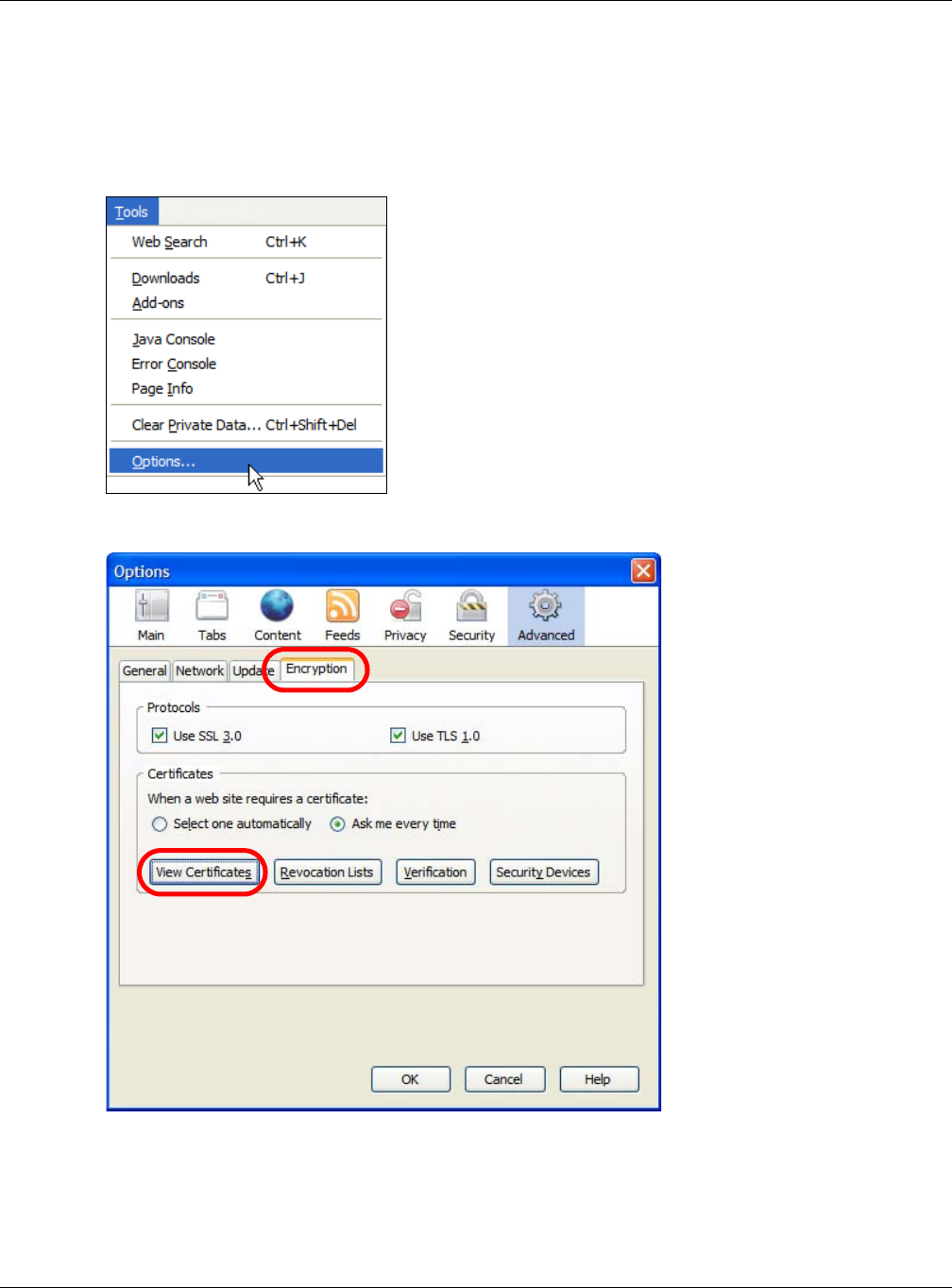
Appendix A Importing Certificates
NWA / WAC Series User’s Guide
223
Installing a Stand-Alone Certificate File in Firefox
Rather than browsing to a Zyxel Web Configurator and installing a public key certificate when
prompted, you can install a stand-alone certificate file if one has been issued to you.
1Open Firefox and click Tools > Options.
2In the Options dialog box, click Advanced > Encryption > View Certificates.
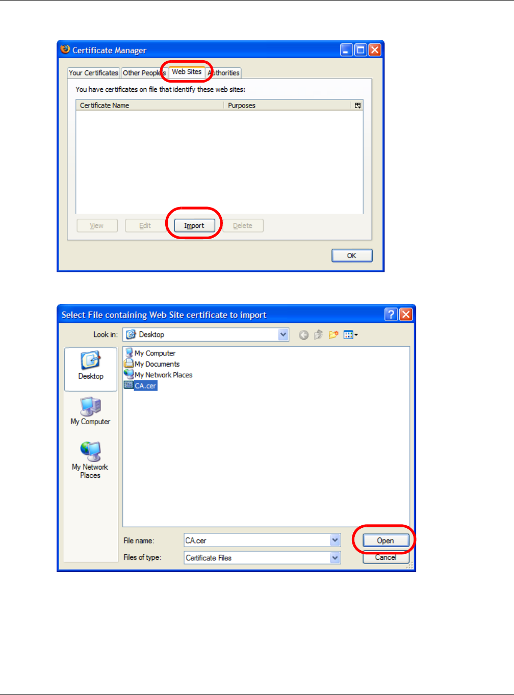
Appendix A Importing Certificates
NWA / WAC Series User’s Guide
224
3In the Certificate Manager dialog box, click Web Sites > Import.
4Use the Select File dialog box to locate the certificate and then click Open.
5The next time you visit the web site, click the padlock in the address bar to open the Page Info > Security
window to see the web page’s security information.
Removing a Certificate in Firefox
This section shows you how to remove a public key certificate in Firefox 2.
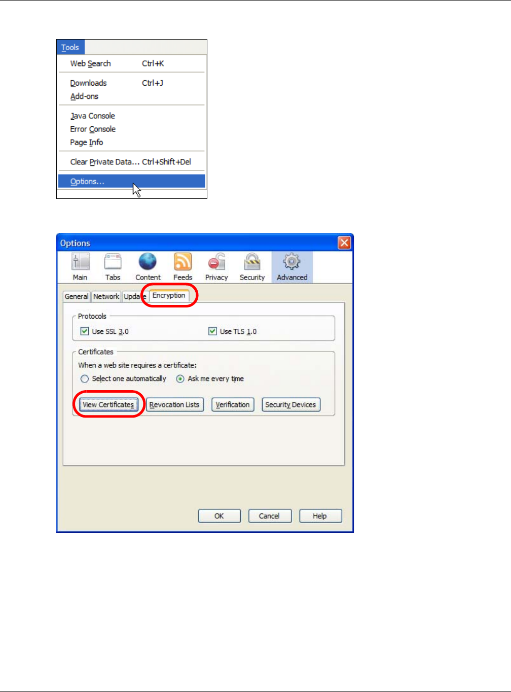
Appendix A Importing Certificates
NWA / WAC Series User’s Guide
225
1Open Firefox and click Tools > Options.
2In the Options dialog box, click Advanced > Encryption > View Certificates.
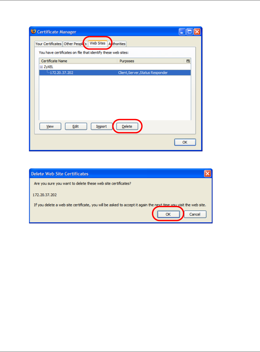
Appendix A Importing Certificates
NWA / WAC Series User’s Guide
226
3In the Certificate Manager dialog box, select the Web Sites tab, select the certificate that you want to
remove, and then click Delete.
4In the Delete Web Site Certificates dialog box, click OK.
5The next time you go to the web site that issued the public key certificate you just removed, a
certification error appears.

NWA / WAC Series User’s Guide
227
APPENDIX B
IPv6
Overview
IPv6 (Internet Protocol version 6), is designed to enhance IP address size and features. The increase in
IPv6 address size to 128 bits (from the 32-bit IPv4 address) allows up to 3.4 x 1038 IP addresses.
IPv6 Addressing
The 128-bit IPv6 address is written as eight 16-bit hexadecimal blocks separated by colons (:). This is an
example IPv6 address 2001:0db8:1a2b:0015:0000:0000:1a2f:0000.
IPv6 addresses can be abbreviated in two ways:
• Leading zeros in a block can be omitted. So 2001:0db8:1a2b:0015:0000:0000:1a2f:0000 can be
written as 2001:db8:1a2b:15:0:0:1a2f:0.
• Any number of consecutive blocks of zeros can be replaced by a double colon. A double colon can
only appear once in an IPv6 address. So 2001:0db8:0000:0000:1a2f:0000:0000:0015 can be
written as 2001:0db8::1a2f:0000:0000:0015, 2001:0db8:0000:0000:1a2f::0015,
2001:db8::1a2f:0:0:15 or 2001:db8:0:0:1a2f::15.
Prefix and Prefix Length
Similar to an IPv4 subnet mask, IPv6 uses an address prefix to represent the network address. An IPv6
prefix length specifies how many most significant bits (start from the left) in the address compose the
network address. The prefix length is written as “/x” where x is a number. For example,
2001:db8:1a2b:15::1a2f:0/32
means that the first 32 bits (2001:db8) is the subnet prefix.
Link-local Address
A link-local address uniquely identifies a device on the local network (the LAN). It is similar to a “private IP
address” in IPv4. You can have the same link-local address on multiple interfaces on a device. A link-
local unicast address has a predefined prefix of fe80::/10. The link-local unicast address format is as
follows.
Table 92 Link-local Unicast Address Format
Global Address
A global address uniquely identifies a device on the Internet. It is similar to a “public IP address” in IPv4. A
global unicast address starts with a 2 or 3.
1111 1110 10 0 Interface ID
10 bits 54 bits 64 bits

Appendix B IPv6
NWA / WAC Series User’s Guide
228
Unspecified Address
An unspecified address (0:0:0:0:0:0:0:0 or ::) is used as the source address when a device does not have
its own address. It is similar to “0.0.0.0” in IPv4.
Loopback Address
A loopback address (0:0:0:0:0:0:0:1 or ::1) allows a host to send packets to itself. It is similar to “127.0.0.1”
in IPv4.
Multicast Address
In IPv6, multicast addresses provide the same functionality as IPv4 broadcast addresses. Broadcasting is
not supported in IPv6. A multicast address allows a host to send packets to all hosts in a multicast group.
Multicast scope allows you to determine the size of the multicast group. A multicast address has a
predefined prefix of ff00::/8. The following table describes some of the predefined multicast addresses.
The following table describes the multicast addresses which are reserved and can not be assigned to a
multicast group.
Table 93 Predefined Multicast Address
MULTICAST ADDRESS DESCRIPTION
FF01:0:0:0:0:0:0:1 All hosts on a local node.
FF01:0:0:0:0:0:0:2 All routers on a local node.
FF02:0:0:0:0:0:0:1 All hosts on a local connected link.
FF02:0:0:0:0:0:0:2 All routers on a local connected link.
FF05:0:0:0:0:0:0:2 All routers on a local site.
FF05:0:0:0:0:0:1:3 All DHCP severs on a local site.
Table 94 Reserved Multicast Address
MULTICAST ADDRESS
FF00:0:0:0:0:0:0:0
FF01:0:0:0:0:0:0:0
FF02:0:0:0:0:0:0:0
FF03:0:0:0:0:0:0:0
FF04:0:0:0:0:0:0:0
FF05:0:0:0:0:0:0:0
FF06:0:0:0:0:0:0:0
FF07:0:0:0:0:0:0:0
FF08:0:0:0:0:0:0:0
FF09:0:0:0:0:0:0:0
FF0A:0:0:0:0:0:0:0
FF0B:0:0:0:0:0:0:0
FF0C:0:0:0:0:0:0:0
FF0D:0:0:0:0:0:0:0
FF0E:0:0:0:0:0:0:0
FF0F:0:0:0:0:0:0:0

Appendix B IPv6
NWA / WAC Series User’s Guide
229
Subnet Masking
Both an IPv6 address and IPv6 subnet mask compose of 128-bit binary digits, which are divided into
eight 16-bit blocks and written in hexadecimal notation. Hexadecimal uses four bits for each character
(1 ~ 10, A ~ F). Each block’s 16 bits are then represented by four hexadecimal characters. For example,
FFFF:FFFF:FFFF:FFFF:FC00:0000:0000:0000.
Interface ID
In IPv6, an interface ID is a 64-bit identifier. It identifies a physical interface (for example, an Ethernet
port) or a virtual interface (for example, the management IP address for a VLAN). One interface should
have a unique interface ID.
EUI-64
The EUI-64 (Extended Unique Identifier) defined by the IEEE (Institute of Electrical and Electronics
Engineers) is an interface ID format designed to adapt with IPv6. It is derived from the 48-bit (6-byte)
Ethernet MAC address as shown next. EUI-64 inserts the hex digits fffe between the third and fourth bytes
of the MAC address and complements the seventh bit of the first byte of the MAC address. See the
following example.
Stateless Autoconfiguration
With stateless autoconfiguration in IPv6, addresses can be uniquely and automatically generated.
Unlike DHCPv6 (Dynamic Host Configuration Protocol version six) which is used in IPv6 stateful
autoconfiguration, the owner and status of addresses don’t need to be maintained by a DHCP server.
Every IPv6 device is able to generate its own and unique IP address automatically when IPv6 is initiated
on its interface. It combines the prefix and the interface ID (generated from its own Ethernet MAC
address, see Interface ID and EUI-64) to form a complete IPv6 address.
When IPv6 is enabled on a device, its interface automatically generates a link-local address (beginning
with fe80).
When the interface is connected to a network with a router and the NWA/WAC is set to automatically
obtain an IPv6 network prefix from the router for the interface, it generates 1another address which
combines its interface ID and global and subnet information advertised from the router. This is a routable
global IP address.
DHCPv6
The Dynamic Host Configuration Protocol for IPv6 (DHCPv6, RFC 3315) is a server-client protocol that
allows a DHCP server to assign and pass IPv6 network addresses, prefixes and other configuration
information to DHCP clients. DHCPv6 servers and clients exchange DHCP messages using UDP.
Table 95
MAC 00 : 13 : 49 : 12 : 34 : 56
Table 96
EUI-64 02: 13 : 49 : FF : FE : 12 : 34 : 56
1. In IPv6, all network interfaces can be associated with several addresses.
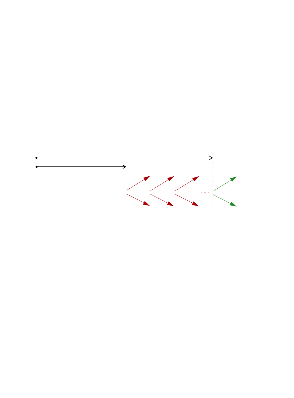
Appendix B IPv6
NWA / WAC Series User’s Guide
230
Each DHCP client and server has a unique DHCP Unique IDentifier (DUID), which is used for identification
when they are exchanging DHCPv6 messages. The DUID is generated from the MAC address, time,
vendor assigned ID and/or the vendor's private enterprise number registered with the IANA. It should not
change over time even after you reboot the device.
Identity Association
An Identity Association (IA) is a collection of addresses assigned to a DHCP client, through which the
server and client can manage a set of related IP addresses. Each IA must be associated with exactly
one interface. The DHCP client uses the IA assigned to an interface to obtain configuration from a DHCP
server for that interface. Each IA consists of a unique IAID and associated IP information.
The IA type is the type of address in the IA. Each IA holds one type of address. IA_NA means an identity
association for non-temporary addresses and IA_TA is an identity association for temporary addresses.
An IA_NA option contains the T1 and T2 fields, but an IA_TA option does not. The DHCPv6 server uses T1
and T2 to control the time at which the client contacts with the server to extend the lifetimes on any
addresses in the IA_NA before the lifetimes expire. After T1, the client sends the server (S1) (from which
the addresses in the IA_NA were obtained) a Renew message. If the time T2 is reached and the server
does not respond, the client sends a Rebind message to any available server (S2). For an IA_TA, the
client may send a Renew or Rebind message at the client's discretion.
DHCP Relay Agent
A DHCP relay agent is on the same network as the DHCP clients and helps forward messages between
the DHCP server and clients. When a client cannot use its link-local address and a well-known multicast
address to locate a DHCP server on its network, it then needs a DHCP relay agent to send a message to
a DHCP server that is not attached to the same network.
The DHCP relay agent can add the remote identification (remote-ID) option and the interface-ID option
to the Relay-Forward DHCPv6 messages. The remote-ID option carries a user-defined string, such as the
system name. The interface-ID option provides slot number, port information and the VLAN ID to the
DHCPv6 server. The remote-ID option (if any) is stripped from the Relay-Reply messages before the relay
agent sends the packets to the clients. The DHCP server copies the interface-ID option from the Relay-
Forward message into the Relay-Reply message and sends it to the relay agent. The interface-ID should
not change even after the relay agent restarts.
Prefix Delegation
Prefix delegation enables an IPv6 router to use the IPv6 prefix (network address) received from the ISP (or
a connected uplink router) for its LAN. The NWA/WAC uses the received IPv6 prefix (for example,
2001:db2::/48) to generate its LAN IP address. Through sending Router Advertisements (RAs) regularly by
multicast, the NWA/WAC passes the IPv6 prefix information to its LAN hosts. The hosts then can use the
prefix to generate their IPv6 addresses.
T1
T2
Renew Rebind
Rebind
to S1
Renew
to S1
Renew
to S1
Renew
to S1
Renew
to S1
Renew
to S1
to S2
to S2

Appendix B IPv6
NWA / WAC Series User’s Guide
231
ICMPv6
Internet Control Message Protocol for IPv6 (ICMPv6 or ICMP for IPv6) is defined in RFC 4443. ICMPv6 has
a preceding Next Header value of 58, which is different from the value used to identify ICMP for IPv4.
ICMPv6 is an integral part of IPv6. IPv6 nodes use ICMPv6 to report errors encountered in packet
processing and perform other diagnostic functions, such as "ping".
Neighbor Discovery Protocol (NDP)
The Neighbor Discovery Protocol (NDP) is a protocol used to discover other IPv6 devices and track
neighbor’s reachability in a network. An IPv6 device uses the following ICMPv6 messages types:
• Neighbor solicitation: A request from a host to determine a neighbor’s link-layer address (MAC
address) and detect if the neighbor is still reachable. A neighbor being “reachable” means it
responds to a neighbor solicitation message (from the host) with a neighbor advertisement message.
• Neighbor advertisement: A response from a node to announce its link-layer address.
• Router solicitation: A request from a host to locate a router that can act as the default router and
forward packets.
• Router advertisement: A response to a router solicitation or a periodical multicast advertisement from
a router to advertise its presence and other parameters.
IPv6 Cache
An IPv6 host is required to have a neighbor cache, destination cache, prefix list and default router list.
The NWA/WAC maintains and updates its IPv6 caches constantly using the information from response
messages. In IPv6, the NWA/WAC configures a link-local address automatically, and then sends a
neighbor solicitation message to check if the address is unique. If there is an address to be resolved or
verified, the NWA/WAC also sends out a neighbor solicitation message. When the NWA/WAC receives a
neighbor advertisement in response, it stores the neighbor’s link-layer address in the neighbor cache.
When the NWA/WAC uses a router solicitation message to query for a router and receives a router
advertisement message, it adds the router’s information to the neighbor cache, prefix list and
destination cache. The NWA/WAC creates an entry in the default router list cache if the router can be
used as a default router.
When the NWA/WAC needs to send a packet, it first consults the destination cache to determine the
next hop. If there is no matching entry in the destination cache, the NWA/WAC uses the prefix list to
determine whether the destination address is on-link and can be reached directly without passing
through a router. If the address is onlink, the address is considered as the next hop. Otherwise, the NWA/
WAC determines the next-hop from the default router list or routing table. Once the next hop IP address
is known, the NWA/WAC looks into the neighbor cache to get the link-layer address and sends the
packet when the neighbor is reachable. If the NWA/WAC cannot find an entry in the neighbor cache or
the state for the neighbor is not reachable, it starts the address resolution process. This helps reduce the
number of IPv6 solicitation and advertisement messages.
Multicast Listener Discovery
The Multicast Listener Discovery (MLD) protocol (defined in RFC 2710) is derived from IPv4's Internet
Group Management Protocol version 2 (IGMPv2). MLD uses ICMPv6 message types, rather than IGMP
message types. MLDv1 is equivalent to IGMPv2 and MLDv2 is equivalent to IGMPv3.

Appendix B IPv6
NWA / WAC Series User’s Guide
232
MLD allows an IPv6 switch or router to discover the presence of MLD listeners who wish to receive
multicast packets and the IP addresses of multicast groups the hosts want to join on its network.
MLD snooping and MLD proxy are analogous to IGMP snooping and IGMP proxy in IPv4.
MLD filtering controls which multicast groups a port can join.
MLD Messages
A multicast router or switch periodically sends general queries to MLD hosts to update the multicast
forwarding table. When an MLD host wants to join a multicast group, it sends an MLD Report message
for that address.
An MLD Done message is equivalent to an IGMP Leave message. When an MLD host wants to leave a
multicast group, it can send a Done message to the router or switch. The router or switch then sends a
group-specific query to the port on which the Done message is received to determine if other devices
connected to this port should remain in the group.
Example - Enabling IPv6 on Windows XP/2003/Vista
By default, Windows XP and Windows 2003 support IPv6. This example shows you how to use the ipv6
install command on Windows XP/2003 to enable IPv6. This also displays how to use the ipconfig
command to see auto-generated IP addresses.
IPv6 is installed and enabled by default in Windows Vista. Use the ipconfig command to check your
automatic configured IPv6 address as well. You should see at least one IPv6 address available for the
interface on your computer.
Example - Enabling DHCPv6 on Windows XP
Windows XP does not support DHCPv6. If your network uses DHCPv6 for IP address assignment, you have
to additionally install a DHCPv6 client software on your Windows XP. (Note: If you use static IP addresses
or Router Advertisement for IPv6 address assignment in your network, ignore this section.)
This example uses Dibbler as the DHCPv6 client. To enable DHCPv6 client on your computer:
C:\>ipv6 install
Installing...
Succeeded.
C:\>ipconfig
Windows IP Configuration
Ethernet adapter Local Area Connection:
Connection-specific DNS Suffix . :
IP Address. . . . . . . . . . . . : 10.1.1.46
Subnet Mask . . . . . . . . . . . : 255.255.255.0
IP Address. . . . . . . . . . . . : fe80::2d0:59ff:feb8:103c%4
Default Gateway . . . . . . . . . : 10.1.1.254
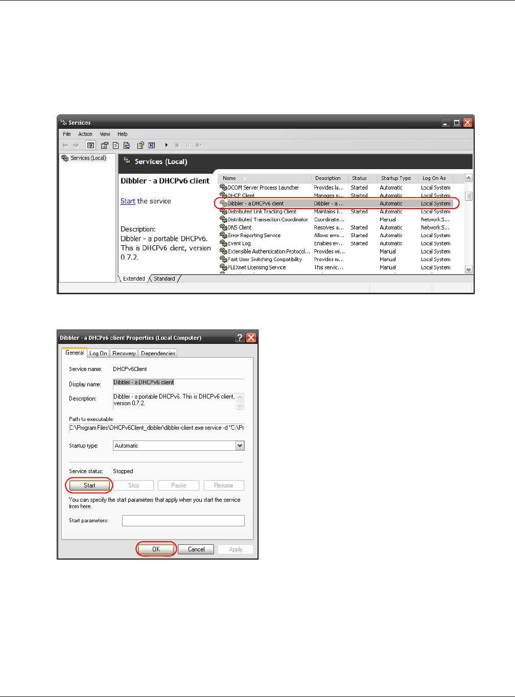
Appendix B IPv6
NWA / WAC Series User’s Guide
233
1Install Dibbler and select the DHCPv6 client option on your computer.
2After the installation is complete, select Start > All Programs > Dibbler-DHCPv6 > Client Install as service.
3Select Start > Control Panel > Administrative Tools > Services.
4Double click Dibbler - a DHCPv6 client.
5Click Start and then OK.
6Now your computer can obtain an IPv6 address from a DHCPv6 server.
Example - Enabling IPv6 on Windows 7
Windows 7 supports IPv6 by default. DHCPv6 is also enabled when you enable IPv6 on a Windows 7
computer.
To enable IPv6 in Windows 7:
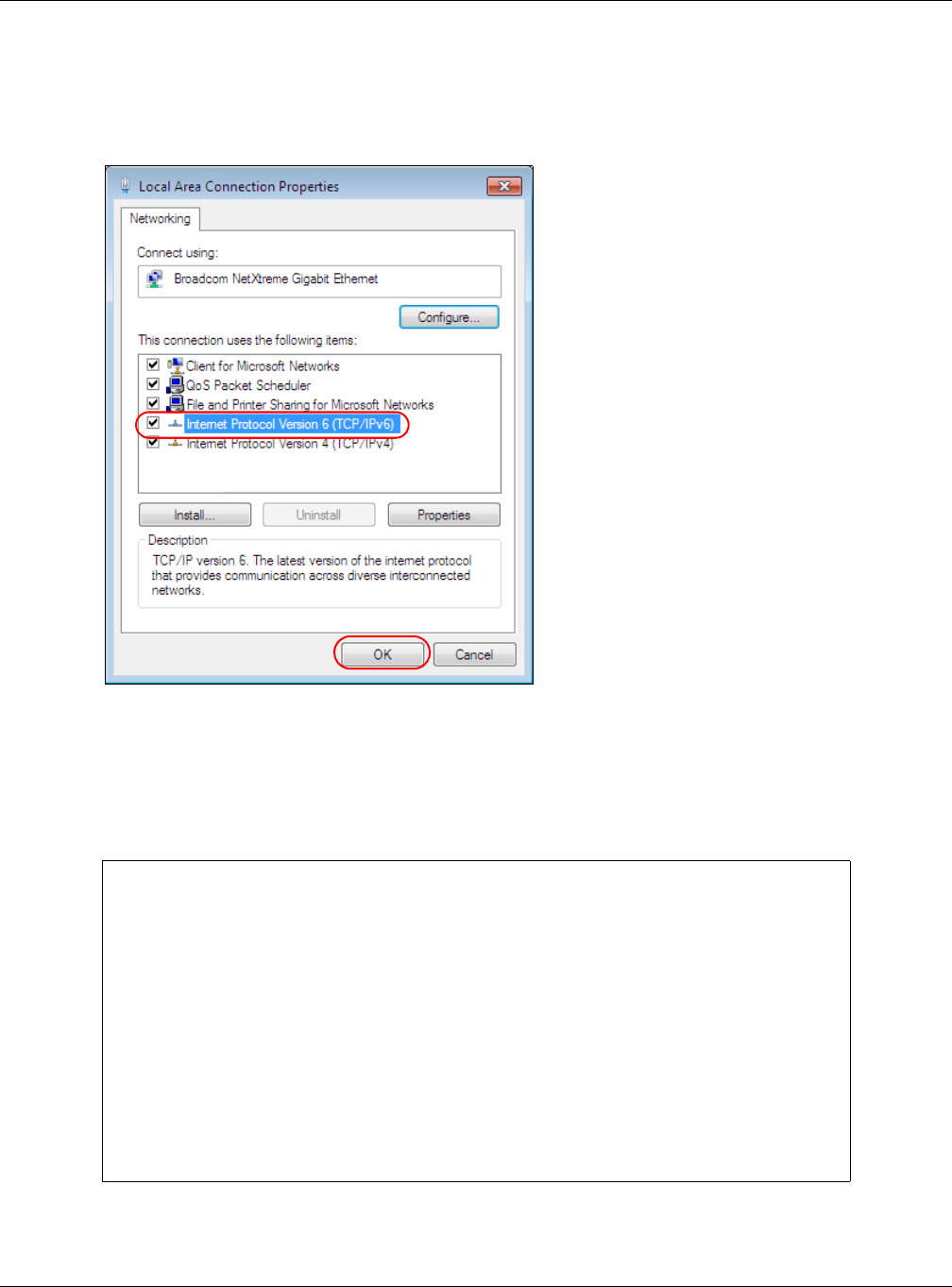
Appendix B IPv6
NWA / WAC Series User’s Guide
234
1Select Control Panel > Network and Sharing Center > Local Area Connection.
2Select the Internet Protocol Version 6 (TCP/IPv6) checkbox to enable it.
3Click OK to save the change.
4Click Close to exit the Local Area Connection Status screen.
5Select Start > All Programs > Accessories > Command Prompt.
6Use the ipconfig command to check your dynamic IPv6 address. This example shows a global address
(2001:b021:2d::1000) obtained from a DHCP server.
C:\>ipconfig
Windows IP Configuration
Ethernet adapter Local Area Connection:
Connection-specific DNS Suffix . :
IPv6 Address. . . . . . . . . . . : 2001:b021:2d::1000
Link-local IPv6 Address . . . . . : fe80::25d8:dcab:c80a:5189%11
IPv4 Address. . . . . . . . . . . : 172.16.100.61
Subnet Mask . . . . . . . . . . . : 255.255.255.0
Default Gateway . . . . . . . . . : fe80::213:49ff:feaa:7125%11
172.16.100.254

NWA / WAC Series User’s Guide
235
APPENDIX C
Customer Support
In the event of problems that cannot be solved by using this manual, you should contact your vendor. If
you cannot contact your vendor, then contact a Zyxel office for the region in which you bought the
device.
See http://www.zyxel.com/homepage.shtml and also
http://www.zyxel.com/about_zyxel/zyxel_worldwide.shtml for the latest information.
Please have the following information ready when you contact an office.
Required Information
• Product model and serial number.
• Warranty Information.
• Date that you received your device.
• Brief description of the problem and the steps you took to solve it.
Corporate Headquarters (Worldwide)
Taiwan
• Zyxel Communications Corporation
• http://www.zyxel.com
Asia
China
• Zyxel Communications (Shanghai) Corp.
Zyxel Communications (Beijing) Corp.
Zyxel Communications (Tianjin) Corp.
• http://www.zyxel.cn
India
•Zyxel Technology India Pvt Ltd
• http://www.zyxel.in
Kazakhstan
•Zyxel Kazakhstan
• http://www.zyxel.kz

Appendix C Customer Support
NWA / WAC Series User’s Guide
236
Korea
• Zyxel Korea Corp.
• http://www.zyxel.kr
Malaysia
• Zyxel Malaysia Sdn Bhd.
• http://www.zyxel.com.my
Pakistan
• Zyxel Pakistan (Pvt.) Ltd.
• http://www.zyxel.com.pk
Philippines
• Zyxel Philippines
• http://www.zyxel.com.ph
Singapore
• Zyxel Singapore Pte Ltd.
• http://www.zyxel.com.sg
Taiwan
• Zyxel Communications Corporation
• http://www.zyxel.com/tw/zh/
Thailand
• Zyxel Thailand Co., Ltd
• http://www.zyxel.co.th
Vietnam
• Zyxel Communications Corporation-Vietnam Office
• http://www.zyxel.com/vn/vi
Europe
Austria
•Zyxel Deutschland GmbH
• http://www.zyxel.de
Belarus
•Zyxel BY
• http://www.zyxel.by

Appendix C Customer Support
NWA / WAC Series User’s Guide
237
Belgium
• Zyxel Communications B.V.
• http://www.zyxel.com/be/nl/
• http://www.zyxel.com/be/fr/
Bulgaria
•Zyxel България
• http://www.zyxel.com/bg/bg/
Czech Republic
• Zyxel Communications Czech s.r.o
• http://www.zyxel.cz
Denmark
• Zyxel Communications A/S
• http://www.zyxel.dk
Estonia
• Zyxel Estonia
• http://www.zyxel.com/ee/et/
Finland
• Zyxel Communications
• http://www.zyxel.fi
France
•Zyxel France
• http://www.zyxel.fr
Germany
•Zyxel Deutschland GmbH
• http://www.zyxel.de
Hungary
• Zyxel Hungary & SEE
• http://www.zyxel.hu
Italy
• Zyxel Communications Italy
• http://www.zyxel.it/

Appendix C Customer Support
NWA / WAC Series User’s Guide
238
Latvia
•Zyxel Latvia
• http://www.zyxel.com/lv/lv/homepage.shtml
Lithuania
•Zyxel Lithuania
• http://www.zyxel.com/lt/lt/homepage.shtml
Netherlands
• Zyxel Benelux
• http://www.zyxel.nl
Norway
• Zyxel Communications
• http://www.zyxel.no
Poland
• Zyxel Communications Poland
• http://www.zyxel.pl
Romania
• Zyxel Romania
• http://www.zyxel.com/ro/ro
Russia
• Zyxel Russia
• http://www.zyxel.ru
Slovakia
• Zyxel Communications Czech s.r.o. organizacna zlozka
• http://www.zyxel.sk
Spain
• Zyxel Communications ES Ltd
• http://www.zyxel.es
Sweden
• Zyxel Communications
• http://www.zyxel.se
Switzerland
•Studerus AG

Appendix C Customer Support
NWA / WAC Series User’s Guide
239
• http://www.zyxel.ch/
Turkey
• Zyxel Turkey A.S.
• http://www.zyxel.com.tr
UK
• Zyxel Communications UK Ltd.
• http://www.zyxel.co.uk
Ukraine
•Zyxel Ukraine
• http://www.ua.zyxel.com
Latin America
Argentina
• Zyxel Communication Corporation
• http://www.zyxel.com/ec/es/
Brazil
• Zyxel Communications Brasil Ltda.
• https://www.zyxel.com/br/pt/
Ecuador
• Zyxel Communication Corporation
• http://www.zyxel.com/ec/es/
Middle East
Israel
• Zyxel Communication Corporation
• http://il.zyxel.com/homepage.shtml
Middle East
• Zyxel Communication Corporation
• http://www.zyxel.com/me/en/

Appendix C Customer Support
NWA / WAC Series User’s Guide
240
North America
USA
• Zyxel Communications, Inc. - North America Headquarters
• http://www.zyxel.com/us/en/
Oceania
Australia
• Zyxel Communications Corporation
• http://www.zyxel.com/au/en/
Africa
South Africa
• Nology (Pty) Ltd.
• http://www.zyxel.co.za

NWA / WAC Series User’s Guide
241
APPENDIX D
Legal Information
Copyright
Copyright © 2017 by Zyxel Communications Corporation.
The contents of this publication may not be reproduced in any part or as a whole, transcribed, stored in a retrieval system, translated into any
language, or transmitted in any form or by any means, electronic, mechanical, magnetic, optical, chemical, photocopying, manual, or
otherwise, without the prior written permission of Zyxel Communications Corporation.
Published by Zyxel Communications Corporation. All rights reserved.
Disclaimers
Zyxel does not assume any liability arising out of the application or use of any products, or software described herein. Neither does it convey any
license under its patent rights nor the patent rights of others. Zyxel further reserves the right to make changes in any products described herein
without notice. This publication is subject to change without notice.
Your use of the NWA/WAC is subject to the terms and conditions of any related service providers.
Trademarks
Trademarks mentioned in this publication are used for identification purposes only and may be properties of their respective owners.
Regulatory Notice and Statement
UNITED STATES of AMERICA
The following information applies if you use the product within USA area.
FCC EMC Statement
• This device complies with part 15 of the FCC Rules. Operation is subject to the following two conditions:
(1) This device may not cause harmful interference, and
(2) this device must accept any interference received, including interference that may cause undesired operation.
• Changes or modifications not expressly approved by the party responsible for compliance could void the user's authority to operate the
device.
• This product has been tested and complies with the specifications for a Class B digital device, pursuant to Part 15 of the FCC Rules. These
limits are designed to provide reasonable protection against harmful interference in a residential installation. This device generates, uses, and
can radiate radio frequency energy and, if not installed and used according to the instructions, may cause harmful interference to radio
communications. However, there is no guarantee that interference will not occur in a particular installation.
• If this device does cause harmful interference to radio or television reception, which is found by turning the device off and on, the user is
encouraged to try to correct the interference by one or more of the following measures:
• Reorient or relocate the receiving antenna
• Increase the separation between the devices
• Connect the equipment to an outlet other than the receiver’s
• Consult a dealer or an experienced radio/TV technician for assistance
FCC Caution: Any changes or modifications not expressly approved by the party responsible for compliance could void the user's authority to
operate this equipment.
FCC Radiation Exposure Statement
• This device complies with FCC RF radiation exposure limits set forth for an uncontrolled environment.
• This transmitter must be at least 20 cm from the user and must not be co-located or operating in conjunction with any other antenna or
transmitter. This transmitter must be at least 22 cm (NWA5123-NI) from the user and must not be co-located or operating in conjunction with
any other antenna or transmitter. This transmitter must be at least 30 cm (WAC6553D-E) from the user and must not be co-located or
operating in conjunction with any other antenna or transmitter.
• Country Code selection feature to be disabled for products marketed to the US/CANADA.
• Operation of this device is restricted to indoor use only. (WAC6553D-E is a device for outdoor use.)
CANADA
The following information applies if you use the product within Canada area.

Appendix D Legal Information
NWA / WAC Series User’s Guide
242
Industry Canada ICES Statement
CAN ICES-3 (B)/NMB-3(B)
Industry Canada RSS-GEN & RSS-247 Statement
• This device complies with Industry Canada license-exempt RSS standard(s). Operation is subject to the following two conditions: (1) this
device may not cause interference, and (2) this device must accept any interference, including interference that may cause undesired
operation of the device.
•This radio transmitter (2468C-NWA5123AC (NWA5123-AC, NWA1123-AC v2), 2468C-NWA5123ACHD (NWA5123-AC HD, NWA1123-AC HD),
2468C-NWA5123NI (NWA5123-NI), 2468C-WAC6502DE (WAC6502D-S, WAC6502D-E), 2468C-WAC6503DS (WAC6503D-S), 2468C-WAC6553DE
(WAC6553D-E), 2468C-WAC6103DI (WAC6103D-I), 2468C-WAC5302DS (WAC5302D-S)) has been approved by Industry Canada to operate
with the antenna types listed below with the maximum permissible gain and required antenna impedance for each antenna type indicated.
Antenna types not included in this list, having a gain greater than the maximum gain indicated for that type, are strictly prohibited for use
with this device.

Appendix D Legal Information
NWA / WAC Series User’s Guide
243
Antenna Information
If the product with 5G wireless function operating in 5150-5250 MHz and 5725-5850 MHz, the following attention must be paid,
• The device for operation in the band 5150-5250 MHz is only for indoor use to reduce the potential for harmful interference to co-channel
mobile satellite systems.
• For devices with detachable antenna(s), the maximum antenna gain permitted for devices in the band 5725-5850 MHz shall be such that the
equipment still complies with the e.i.r.p. limits specified for point-to-point and non-point-to-point operation as appropriate; and
• The worst-case tilt angle(s) necessary to remain compliant with the e.i.r.p. elevation mask requirement set forth in Section 6.2.2(3) of RSS 247
shall be clearly indicated.
ANTENNA MODEL NO. TYPE CONNECTOR 2.4 G GAIN 5G GAIN REMARK
NWA5123-AC 2.4 GHz
Antenna
1 PIFA U.FL 3.08 (2400-2483.5 MHz)
2 PIFA U.FL 3.07 (2400-2483.5 MHz)
NWA5123-AC 5 GHz
Antenna
3 PIFA U.FL 4.06 (5150-5250 MHz)
3.91 (5725-5850 MHz)
4 PIFA U.FL 3.99 (5150-5250 MHz)
3.79 (5725-5850 MHz)
NWA5123-AC HD 1PIFA I-PEX 3 (2400-2483.5 MHz)
NWA5123-AC HD 2PIFA I-PEX 3 (2400-2483.5 MHz)
NWA5123-AC HD 3Monopole I-PEX 4 (5150-5250 MHz)
4 (5725-5850 MHz)
NWA5123-AC HD 4Monopole I-PEX 4 (5150-5250 MHz)
4 (5725-5850 MHz)
NWA5123-AC HD 5Monopole I-PEX 4 (5150-5250 MHz)
4 (5725-5850 MHz)
NWA1123-AC HD 1PIFA I-PEX 3 (2400-2483.5 MHz)
NWA1123-AC HD 2PIFA I-PEX 3 (2400-2483.5 MHz)
NWA1123-AC HD 3Monopole I-PEX 4 (5150-5250 MHz)
4 (5725-5850 MHz)
NWA1123-AC HD 4Monopole I-PEX 4 (5150-5250 MHz)
4 (5725-5850 MHz)
NWA1123-AC HD 5Monopole I-PEX 4 (5150-5250 MHz)
4 (5725-5850 MHz)
WAC6502D-E Dipole RSMA 5 7
WAC6502D-S Dipole IPEX 4 6
WAC6503D-S Dipole IPEX 4 6
ZXL04-22008A Dipole N type 4.5 7
SINBON / 2.4 G & 5 G
Metal & PCB Antenna
1 PIFA U.FL 3.28 Ceiling Mounted:
Antenna 1, 2, 3
Wall Mounted:
Antenna 1, 2, 4
2PIFA U.FL 3.37
3PIFA U.FL 3.15
4Dipole U.FL 4.33
5 Loop U.FL 4.38 (5150-5250 MHz)
4.23 (5725-5850 MHz)
Ceiling Mounted:
Antenna 5, 6, 7
Wall Mounted:
Antenna 5, 6, 8
6 Loop U.FL 4.31 (5150-5250 MHz)
4.22 (5725-5850 MHz)
7 Loop U.FL 4.38 (5150-5250 MHz)
4.36 (5725-5850 MHz)
8 Dipole U.FL 5.12 (5150-5250 MHz)
5.20 (5725-5850 MHz)
81XCAL15.G01 Loop I-PEX 5.82 (2400-2483.5 MHz)
81XCAL15.G02 Loop I-PEX 5.02 (2400-2483.5 MHz)
AD751 PIFA I-PEX 5 (5150-5250 MHz)
5 (5250-5350 MHz)
5 (5470-5725 MHz)
5 (5725-5850 MHz)
A9701685 PCB U.FL 4.0
A9701686 PCB U.FL 5.8
A9701670 PCB U.FL 5.2
A9701671 PCB U.FL 6.1

Appendix D Legal Information
NWA / WAC Series User’s Guide
244
If the product with 5G wireless function operating in 5250-5350 MHz and 5470-5725 MHz, the following attention must be paid.
• For devices with detachable antenna(s), the maximum antenna gain permitted for devices in the bands 5250-5350 MHz and 5470-5725 MHz
shall be such that the equipment still complies with the e.i.r.p. limit.
• Le présent appareil est conforme aux CNR d’Industrie Canada applicables aux appareils radio exempts de licence. L’exploitation est
autorisée aux deux conditions suivantes : (1) l’appareil ne doit pas produire de brouillage, et (2) l’utilisateur de l’appareil doit accepter tout
brouillage radioélectrique subi, même si le brouillage est susceptible d’en compromettre le fonctionnement.
•Le présent émetteur radio (2468C-NWA5123AC (NWA5123-AC, NWA1123-AC v2), 2468C-NWA5123ACHD (NWA5123-AC HD, NWA1123-AC
HD), 2468C-NWA5123NI (NWA5123-NI), 2468C-WAC6502DE (WAC6502D-S, WAC6502D-E), 2468C-WAC6503DS (WAC6503D-S), 2468C-
WAC6553DE (WAC6553D-E), 2468C-WAC6103DI (WAC6103D-I), 2468C-WAC5302DS (WAC5302D-S)) de modèle s'il fait partie du matériel de
catégorieI) a été approuvé par Industrie Canada pour fonctionner avec les types d'antenne énumérés ci-dessous et ayant un gain
admissible maximal et l'impédance requise pour chaque type d'antenne. Les types d'antenne non inclus dans cette liste, ou dont le gain est
supérieur au gain maximal indiqué, sont strictement interdits pour l'exploitation de l'émetteur.

Appendix D Legal Information
NWA / WAC Series User’s Guide
245
Informations Antenne
Lorsque la fonction sans fil 5G fonctionnant en 5150-5250 MHz and 5725-5850 MHz est activée pour ce produit , il est nécessaire de porter une
attention particulière aux choses suivantes
• Les dispositifs fonctionnant dans la bande 5150-5250 MHz sont réservés uniquement pour une utilisation à l’intérieur afin de réduire les risques
de brouillage préjudiciable aux systèmes de satellites mobiles utilisant les mêmes canaux;
• Pour les dispositifs munis d’antennes amovibles, le gain maximal d'antenne permis (pour les dispositifs utilisant la bande de 5 725 à 5 850 MHz)
doit être conforme à la limite de la p.i.r.e. spécifiée pour l'exploitation point à point et l’exploitation non point à point, selon le cas;
MODÈLE D'ANTENNE NB. TYPE CONNECTEUR 2.4 G GAIN 5G GAIN REMARQUE
NWA5123-AC 2.4 GHz
Antenna
1 PIFA U.FL 3.08 (2400-2483.5 MHz)
2 PIFA U.FL 3.07 (2400-2483.5 MHz)
NWA5123-AC 5 GHz
Antenna
3 PIFA U.FL 4.06 (5150-5250 MHz)
3.91 (5725-5850 MHz)
4 PIFA U.FL 3.99 (5150-5250 MHz)
3.79 (5725-5850 MHz)
NWA5123-AC HD 1PIFA I-PEX 3 (2400-2483.5 MHz)
NWA5123-AC HD 2PIFA I-PEX 3 (2400-2483.5 MHz)
NWA5123-AC HD 3Monopole I-PEX 4 (5150-5250 MHz)
4 (5725-5850 MHz)
NWA5123-AC HD 4Monopole I-PEX 4 (5150-5250 MHz)
4 (5725-5850 MHz)
NWA5123-AC HD 5Monopole I-PEX 4 (5150-5250 MHz)
4 (5725-5850 MHz)
NWA1123-AC HD 1PIFA I-PEX 3 (2400-2483.5 MHz)
NWA1123-AC HD 2PIFA I-PEX 3 (2400-2483.5 MHz)
NWA1123-AC HD 3Monopole I-PEX 4 (5150-5250 MHz)
4 (5725-5850 MHz)
NWA1123-AC HD 4Monopole I-PEX 4 (5150-5250 MHz)
4 (5725-5850 MHz)
NWA1123-AC HD 5Monopole I-PEX 4 (5150-5250 MHz)
4 (5725-5850 MHz)
WAC6502D-E Dipole RSMA 5 7
WAC6502D-S Dipole IPEX 4 6
WAC6503D-S Dipole IPEX 4 6
ZXL04-22008A Dipole N type 4.5 7
SINBON / 2.4 G & 5 G
Metal & PCB Antenna
1 PIFA U.FL 3.28 Ceiling Mounted:
Antenna 1, 2, 3
Wall Mounted:
Antenna 1, 2, 4
2PIFA U.FL 3.37
3PIFA U.FL 3.15
4Dipole U.FL 4.33
5 Loop U.FL 4.38 (5150-5250 MHz)
4.23 (5725-5850 MHz)
Ceiling Mounted:
Antenna 5, 6, 7
Wall Mounted:
Antenna 5, 6, 8
6 Loop U.FL 4.31 (5150-5250 MHz)
4.22 (5725-5850 MHz)
7 Loop U.FL 4.38 (5150-5250 MHz)
4.36 (5725-5850 MHz)
8 Dipole U.FL 5.12 (5150-5250 MHz)
5.20 (5725-5850 MHz)
81XCAL15.G01 Loop I-PEX 5.82 (2400-2483.5 MHz)
81XCAL15.G02 Loop I-PEX 5.02 (2400-2483.5 MHz)
AD751 PIFA I-PEX 5 (5150-5250 MHz)
5 (5250-5350 MHz)
5 (5470-5725 MHz)
5 (5725-5850 MHz)
A9701685 PCB U.FL 4.0
A9701686 PCB U.FL 5.8
A9701670 PCB U.FL 5.2
A9701671 PCB U.FL 6.1

Appendix D Legal Information
NWA / WAC Series User’s Guide
246
• Les pires angles d’inclinaison nécessaires pour rester conforme à l’exigence de la p.i.r.e. applicable au masque d’élévation, et énoncée à la
section 6.2.2 3) du CNR-247, doivent être clairement indiqués.
Lorsque la fonction sans fil 5G fonctionnant en 5250-5350 MHz et 5470-5725 MHz est activée pour ce produit , il est nécessaire de porter une
attention particulière aux choses suivantes.
• Pour les dispositifs munis d’antennes amovibles, le gain maximal d'antenne permis pour les dispositifs utilisant les bandes de 5 250 à 5 350 MHz
et de 5 470 à 5 725 MHz doit être conforme à la limite de la p.i.r.e.
Industry Canada radiation exposure statement
This equipment complies with IC radiation exposure limits set forth for an uncontrolled environment. This equipment should be installed and
operated with a minimum distance of 20 cm between the radiator and your body.
This equipment complies with IC radiation exposure limits set forth for an uncontrolled environment. This equipment should be installed
and operated with a minimum distance of 22cm (NWA5123-NI, NWA5123-AC HD, NWA1123-AC HD) between the radiator and your body.
This equipment complies with IC radiation exposure limits set forth for an uncontrolled environment. This equipment should be installed and
operated with a minimum distance of 30 cm (WAC6553D-E) between the radiator and your body.
Déclaration d’exposition aux radiations:
Cet équipement est conforme aux limites d’exposition aux rayonnements IC établies pour un environnement non contrôlé.Cet équipement doit
être installé et utilisé avec un minimum de 20 cm de distance entre la source de rayonnement et votre corps.
Cet équipement est conforme aux limites d’exposition aux rayonnements IC établies pour un environnement non contrôlé.Cet équipement
doit être installé et utilisé avec un minimum de 22 cm (NWA5123-NI, NWA5123-AC HD, NWA1123-AC HD) de distance entre la source de
rayonnement et votre corps.
Cet équipement est conforme aux limites d’exposition aux rayonnements IC établies pour un environnement non contrôlé.Cet équipement doit
être installé et utilisé avec un minimum de 30 cm (WAC6553D-E) de distance entre la source de rayonnement et votre corps.
Caution:
(i) the device for operation in the band 5150-5250 MHz is only for indoor use to reduce the potential for harmful interference to co-channel
mobile satellite systems;
(ii) the maximum antenna gain permitted for devices in the bands 5250-5350 MHz and 5470-5725 MHz shall comply with the e.i.r.p. limit; and
(iii) the maximum antenna gain permitted for devices in the band 5725-5825 MHz shall comply with the e.i.r.p. limits specified for point-to-point
and non point-to-point operation as appropriate.
(iv) Users should also be advised that high-power radars are allocated as primary users (i.e. priority users) of the bands 5250-5350 MHz and 5650-
5850 MHz and that these radars could cause interference and/or damage to LE-LAN devices.
(v) WAC6553D-E is an outdoor device and only uses 5G Band 4 (5725-5850 MHz).
Avertissement:
(i) les dispositifs fonctionnant dans la bande 5150-5250 MHz sont réservés uniquement pour une utilisation à l’intérieur afin de réduire les risques
de brouillage préjudiciable aux systèmes de satellites mobiles utilisant les mêmes canaux;
(ii) le gain maximal d’antenne permis pour les dispositifs utilisant les bandes 5250-5350 MHz et 5 470-5 725 MHz doit se conformer à la limite de
p.i.r.e.;
(iii) le gain maximal d’antenne permis (pour les dispositifs utilisant la bande 5725-5825 MHz) doit se conformer à la limite de p.i.r.e. spécifiée pour
l’exploitation point à point et non point à point, selon le cas.
(iv) De plus, les utilisateurs devraient aussi être avisés que les utilisateurs de radars de haute puissance sont désignés utilisateurs principaux (c.-à-
d., qu’ils ont la priorité) pour les bandes 5250-5350 MHz et 5650-5850 MHz et que ces radars pourraient causer du brouillage et/ou des
dommages aux dispositifs LAN-EL.
(v) WAC6553D-E est un appareil exterieur et seulement utilise 5G Bane 4 (5725-5850 MHz).
EUROPEAN UNION
The following information applies if you use the product within the European Union.
Declaration of Conformity with Regard to EU Directive 2014/53/EU (Radio Equipment Directive, RED)
• Compliance information for 2.4GHz and/or 5GHz wireless products relevant to the EU and other Countries following the EU Directive 2014/53/
EU (RED). And this product may be used in all EU countries (and other countries following the EU Directive 2014/53/EU) without any limitation
except for the countries mentioned below table:
• In the majority of the EU and other European countries, the 5GHz bands have been made available for the use of wireless local area
networks (LANs). Later in this document you will find an overview of countries in which additional restrictions or requirements or both are
applicable. The requirements for any country may evolve. Zyxel recommends that you check with the local authorities for the latest status of
their national regulations for the 5GHz wireless LANs.
• If this device for operation in the band 5150-5350 MHz, it is for indoor use only.
NWA5123-AC
• This equipment should be installed and operated with a minimum distance of 20 cm between the radio equipment and your body.
• The maximum RF power operating for each band as follows:
• The band 2,400 to 2,483.5 MHz is 97.95 mW,
• The bands 5,150 MHz to 5,350 MHz is 199.07 mW,

Appendix D Legal Information
NWA / WAC Series User’s Guide
247
• The 5,470 MHz to 5,725 MHz is 743.02 mW.
NWA1123-ACv2
• This equipment should be installed and operated with a minimum distance of 20 cm between the radio equipment and your body.
• The maximum RF power operating for each band as follows:
• The band 2,400 to 2,483.5 MHz is 97.95 mW,
• The bands 5,150 MHz to 5,350 MHz is 199.07 mW,
• The 5,470 MHz to 5,725 MHz is 743.02 mW.
NWA5121-N
• This equipment should be installed and operated with a minimum distance of 20 cm between the radio equipment and your body.
• The maximum RF power operating for each band as follow:
• The band 2,400 to 2,483.5 MHz is 84.72 mW,
NWA5123-NI
• This equipment should be installed and operated with a minimum distance of 20 cm between the radio equipment and your body.
• The maximum RF power operating for each band as follows:
• The band 2,400 to 2,483.5 MHz is 90.99 mW,
• The bands 5,150 MHz to 5,350 MHz is 183.65 mW,
• The 5,470 MHz to 5,725 MHz is 558.47 mW.
NWA5301-NJ
• This equipment should be installed and operated with a minimum distance of 20 cm between the radio equipment and your body.
• The maximum RF power operating for each band as follows:
• The band 2,400 to 2,483.5 MHz is 90.57 mW,
WAC6503D-S
• This equipment should be installed and operated with a minimum distance of 20 cm between the radio equipment and your body.
• The maximum RF power operating for each band as follows:
• The band 2,400 to 2,483.5 MHz is 99.54 mW,
• The bands 5,150 MHz to 5,350 MHz is 183.65 mW,
• The 5,470 MHz to 5,725 MHz is 941.89 mW.
WAC6502D-S
• This equipment should be installed and operated with a minimum distance of 20 cm between the radio equipment and your body.
• The maximum RF power operating for each band as follows:
• The band 2,400 to 2,483.5 MHz is 94.19 mW,
• The bands 5,150 MHz to 5,350 MHz is 194.98 mW,
• The 5,470 MHz to 5,725 MHz is 986.28 mW.
WAC6502D-E
• This equipment should be installed and operated with a minimum distance of 20 cm between the radio equipment and your body.
• The maximum RF power operating for each band as follows:
• The band 2,400 to 2,483.5 MHz is 94.19 mW,
• The bands 5,150 MHz to 5,350 MHz is 194.98 mW,
• The 5,470 MHz to 5,725 MHz is 986.28 mW.
WAC6553D-E
• This equipment should be installed and operated with a minimum distance of 20 cm between the radio equipment and your body.
• The maximum RF power operating for each band as follows:
• The band 2,400 to 2,483.5 MHz is 92.26 mW,
• The bands 5,150 MHz to 5,350 MHz is 198.61 mW,
• The 5,470 MHz to 5,725 MHz is 995.41 mW.
WAC6103D-I
• This equipment should be installed and operated with a minimum distance of 20 cm between the radio equipment and your body.
• The maximum RF power operating for each band as follows:
• The band 2,400 to 2,483.5 MHz is 92.68 mW,
• The bands 5,150 MHz to 5,350 MHz is 192.75 mW,
• The 5,470 MHz to 5,725 MHz is 966.05 mW.
WAC5302D-S
• This equipment should be installed and operated with a minimum distance of 20 cm between the radio equipment and your body.
• The maximum RF power operating for each band as follows:
• The band 2,400 to 2,483.5 MHz is 93.33 mW,
• The bands 5,150 MHz to 5,350 MHz is 192.31 mW,
• The 5,470 MHz to 5,725 MHz is 391.74 mW.
NWA1123-AC PRO
• This equipment should be installed and operated with a minimum distance of 20 cm between the radio equipment and your body.
• The maximum RF power operating for each band as follows:
• The band 2,400 to 2,483.5 MHz is 92.68 mW,
• The bands 5,150 MHz to 5,350 MHz is 192.75 mW,
• The 5,470 MHz to 5,725 MHz is 966.05 mW.
NWA1123-AC HD
• This equipment should be installed and operated with a minimum distance of 20 cm between the radio equipment and your body.
• The maximum RF power operating for each band as follows:
• The band 2,400 to 2,483.5 MHz is 97.274 mW,
• The bands 5,150 MHz to 5,350 MHz is 198.61 mW,
• The 5,470 MHz to 5,725 MHz is 995.40 mW.

Appendix D Legal Information
NWA / WAC Series User’s Guide
248
NWA5123-AC HD
• This equipment should be installed and operated with a minimum distance of 20 cm between the radio equipment and your body.
• The maximum RF power operating for each band as follows:
• The band 2,400 to 2,483.5 MHz is 97.274 mW,
• The bands 5,150 MHz to 5,350 MHz is 198.61 mW,
• The 5,470 MHz to 5,725 MHz is 995.40 mW.
Български
(Bulgarian)
С настоящото Zyxel декларира, че това оборудване е в съответствие със съществените изисквания и другите
приложими разпоредбите на Директива 2014/53/ЕC.
National Restrictions
• The Belgian Institute for Postal Services and Telecommunications (BIPT) must be notified of any outdoor wireless link
having a range exceeding 300 meters. Please check http://www.bipt.be for more details.
• Draadloze verbindingen voor buitengebruik en met een reikwijdte van meer dan 300 meter dienen aangemeld te
worden bij het Belgisch Instituut voor postdiensten en telecommunicatie (BIPT). Zie http://www.bipt.be voor meer
gegevens.
• Les liaisons sans fil pour une utilisation en extérieur d’une distance supérieure à 300 mètres doivent être notifiées à
l’Institut Belge des services Postaux et des Télécommunications (IBPT). Visitez http://www.ibpt.be pour de plus amples
détails.
Español
(Spanish)
Por medio de la presente Zyxel declara que el equipo cumple con los requisitos esenciales y cualesquiera otras
disposiciones aplicables o exigibles de la Directiva 2014/53/UE..
Čeština
(Czech)
Zyxel tímto prohlašuje, že tento zařízení je ve shodě se základními požadavky a dalšími příslušnými ustanoveními směrnice
2014/53/EU.
Dansk (Danish) Undertegnede Zyxel erklærer herved, at følgende udstyr udstyr overholder de væsentlige krav og øvrige relevante krav i
direktiv 2014/53/EU.
National Restrictions
• In Denmark, the band 5150 - 5350 MHz is also allowed for outdoor usage.
• I Danmark må frekvensbåndet 5150 - 5350 også anvendes udendørs.
Deutsch
(German)
Hiermit erklärt Zyxel, dass sich das Gerät Ausstattung in Übereinstimmung mit den grundlegenden Anforderungen und den
übrigen einschlägigen Bestimmungen der Richtlinie 2014/53/EU befindet.
Eesti keel
(Estonian)
Käesolevaga kinnitab Zyxel seadme seadmed vastavust direktiivi 2014/53/EU põhinõuetele ja nimetatud direktiivist
tulenevatele teistele asjakohastele sätetele.
Ελληνικά
(Greek)
ΜΕ ΤΗΝ ΠΑΡΟΥΣΑ Zyxel ∆ΗΛΩΝΕΙ ΟΤΙ εξοπλισμός ΣΥΜΜΟΡΦΩΝΕΤΑΙ ΠΡΟΣ ΤΙΣ ΟΥΣΙΩ∆ΕΙΣ ΑΠΑΙΤΗΣΕΙΣ ΚΑΙ ΤΙΣ ΛΟΙΠΕΣ ΣΧΕΤΙΚΕΣ
∆ΙΑΤΑΞΕΙΣ ΤΗΣ Ο∆ΗΓΙΑΣ 2014/53/EU.
English Hereby, Zyxel declares that this device is in compliance with the essential requirements and other relevant provisions of
Directive 2014/53/EU.
Français
(French)
Par la présente Zyxel déclare que l'appareil équipements est conforme aux exigences essentielles et aux autres dispositions
pertinentes de la directive 2014/53/EU.
Hrvatski
(Croatian)
Zyxel ovime izjavljuje da je radijska oprema tipa u skladu s Direktivom 2014/53/EU.
Íslenska
(Icelandic)
Hér með lýsir, Zyxel því yfir að þessi búnaður er í samræmi við grunnkröfur og önnur viðeigandi ákvæði tilskipunar 2014/53/
EU.
Italiano (Italian) Con la presente Zyxel dichiara che questo attrezzatura è conforme ai requisiti essenziali ed alle altre disposizioni pertinenti
stabilite dalla direttiva 2014/53/EU.
National Restrictions
• This product meets the National Radio Interface and the requirements specified in the National Frequency Allocation
Table for Italy. Unless this wireless LAN product is operating within the boundaries of the owner's property, its use requires
a “general authorization.” Please check http://www.sviluppoeconomico.gov.it/ for more details.
• Questo prodotto è conforme alla specifiche di Interfaccia Radio Nazionali e rispetta il Piano Nazionale di ripartizione
delle frequenze in Italia. Se non viene installato all 'interno del proprio fondo, l'utilizzo di prodotti Wireless LAN richiede
una “Autorizzazione Generale”. Consultare http://www.sviluppoeconomico.gov.it/ per maggiori dettagli.
Latviešu valoda
(Latvian)
Ar šo Zyxel deklarē, ka iekārtas atbilst Direktīvas 2014/53/EU būtiskajām prasībām un citiem ar to saistītajiem noteikumiem.
National Restrictions
• The outdoor usage of the 2.4 GHz band requires an authorization from the Electronic Communications Office. Please
check http://www.esd.lv for more details.
• 2.4 GHz frekvenèu joslas izmantoðanai ârpus telpâm nepiecieðama atïauja no Elektronisko sakaru direkcijas. Vairâk
informâcijas: http://www.esd.lv.
Lietuvių kalba
(Lithuanian)
Šiuo Zyxel deklaruoja, kad šis įranga atitinka esminius reikalavimus ir kitas 2014/53/EU Direktyvos nuostatas.
Magyar
(Hungarian)
Alulírott, Zyxel nyilatkozom, hogy a berendezés megfelel a vonatkozó alapvetõ követelményeknek és az 2014/53/EU
irányelv egyéb elõírásainak.
Malti (Maltese) Hawnhekk, Zyxel, jiddikjara li dan tagħmir jikkonforma mal-ħtiġijiet essenzjali u ma provvedimenti oħrajn relevanti li hemm
fid-Dirrettiva 2014/53/EU.
Nederlands
(Dutch)
Hierbij verklaart Zyxel dat het toestel uitrusting in overeenstemming is met de essentiële eisen en de andere relevante
bepalingen van richtlijn 2014/53/EU.

Appendix D Legal Information
NWA / WAC Series User’s Guide
249
Notes:
1. Although Norway, Switzerland and Liechtenstein are not EU member states, the EU Directive 2014/53/EU has also been implemented in those
countries.
2. The regulatory limits for maximum output power are specified in EIRP. The EIRP level (in dBm) of a device can be calculated by adding the
gain of the antenna used (specified in dBi) to the output power available at the connector (specified in dBm).
List of national codes
Professional installation instruction (WAC6553D-E)
Please be advised that due to the unique function supplied by this product, the device is intended for use with our interactive entertainment
software and licensed third-party only. The product will be distributed through controlled distribution channel and installed by trained
professional and will not be sold directly to the general public through retail store.
1Installation personal
This product is designed for specific application and needs to be installed by a qualified personal who has RF and related rule knowledge. The
general user shall not attempt to install or change the setting.
2Installation location
The product shall be installed at a location where the radiating antenna can be kept 30 cm from nearby person in normal operation condition
to meet regulatory RF exposure requirement.
3External antenna
Use only the antennas which have been approved by Zyxel Communications Corporation. The non-approved antenna(s) may produce
unwanted spurious or excessive RF transmitting power which may lead to the violation of FCC/IC limit and is prohibited.
4Installation procedure
Polski (Polish) Niniejszym Zyxel oświadcza, że sprzęt jest zgodny z zasadniczymi wymogami oraz pozostałymi stosownymi postanowieniami
Dyrektywy 2014/53/EU.
Português
(Portuguese)
Zyxel declara que este equipamento está conforme com os requisitos essenciais e outras disposições da Directiva 2014/53/
EU.
Română
(Romanian)
Prin prezenta, Zyxel declară că acest echipament este în conformitate cu cerinţele esenţiale şi alte prevederi relevante ale
Directivei 2014/53/EU.
Slovenčina
(Slovak)
Zyxel týmto vyhlasuje, že zariadenia spĺňa základné požiadavky a všetky príslušné ustanovenia Smernice 2014/53/EU.
Slovenščina
(Slovene)
Zyxel izjavlja, da je ta oprema v skladu z bistvenimi zahtevami in ostalimi relevantnimi določili direktive 2014/53/EU.
Suomi (Finnish) Zyxel vakuuttaa täten että laitteet tyyppinen laite on direktiivin 2014/53/EU oleellisten vaatimusten ja sitä koskevien
direktiivin muiden ehtojen mukainen.
Svenska
(Swedish)
Härmed intygar Zyxel att denna utrustning står I överensstämmelse med de väsentliga egenskapskrav och övriga relevanta
bestämmelser som framgår av direktiv 2014/53/EU.
Norsk
(Norwegian)
Erklærer herved Zyxel at dette utstyret er I samsvar med de grunnleggende kravene og andre relevante bestemmelser I
direktiv 2014/53/EU.
COUNTRY ISO 3166 2 LETTER CODE COUNTRY ISO 3166 2 LETTER CODE
Austria AT Liechtenstein LI
Belgium BE Lithuania LT
Bulgaria BG Luxembourg LU
Croatia HR Malta MT
Cyprus CY Netherlands NL
Czech Republic CR Norway NO
Denmark DK Poland PL
Estonia EE Portugal PT
Finland FI Romania RO
France FR Serbia RS
Germany DE Slovakia SK
Greece GR Slovenia SI
Hungary HU Spain ES
Iceland IS Sweden SE
Ireland IE Switzerland CH
Italy IT Turkey TR
Latvia LV United Kingdom GB

Appendix D Legal Information
NWA / WAC Series User’s Guide
250
Please refer to user's manual for the detail.
5Warning
Please carefully select the installation position and make sure that the final output power does not exceed the limit set force in relevant rules. The
violation of the rule could lead to serious federal penalty.
Instructions d'installation professionnelle (WAC6553D-E)
Veuillez noter que l'appareil etant dedie a une fonction unique, il doit etre utilise avec notre logiciel proprietaire de divertissement interactif . Ce
produit sera propose par un reseau de distribution controle et installe par des professionels; il ne sera pas propose au grand public par le reseau
de la grande distribution.
1Installation
Ce produit est destine a un usage specifique et doit etre installe par un personnel qualifie maitrisant les radiofrequences et les regles s'y
rapportant. L'installation et les reglages ne doivent pas etre modifies par l'utilisateur final.
2Emplacement d'installation
En usage normal, afin de respecter les exigences reglementaires concernant l'exposition aux radiofrequences, ce produit doit etre installe de
facon a respecter une distance de 30 cm entre l'antenne emettrice et les personnes.
3Antenn externe.
Utiliser uniiquement les antennes approuvees par le fabricant. L'utilisation d'autres antennes peut conduire a un niveau de rayonnement
essentiel ou non essentiel depassant les niveaux limites definis par FCC/IC, ce qui est interdit.
4Procedure d'installation
Consulter le manuel d'utilisation.
5Avertissement
Choisir avec soin la position d'installation et s'assurer que la puissance de sortie ne depasse pas les limites en vigueur. La violation de cette regle
peut conduire a de serieuses penalites federales.
Safety Warnings
• Do not use this product near water, for example, in a wet basement or near a swimming pool.
• Do not expose your device to dampness, dust or corrosive liquids.
• Do not store things on the device.
• Do not obstruct the device ventilation slots as insufficient airflow may harm your device. For example, do not place the device in an
enclosed space such as a box or on a very soft surface such as a bed or sofa.
• Do not install, use, or service this device during a thunderstorm. There is a remote risk of electric shock from lightning.
• Connect ONLY suitable accessories to the device.
• Do not open the device or unit. Opening or removing covers can expose you to dangerous high voltage points or other risks. ONLY qualified
service personnel should service or disassemble this device. Please contact your vendor for further information.
• Make sure to connect the cables to the correct ports.
• Place connecting cables carefully so that no one will step on them or stumble over them.
• Always disconnect all cables from this device before servicing or disassembling.
• Do not remove the plug and connect it to a power outlet by itself; always attach the plug to the power adaptor first before connecting it to
a power outlet.
• Do not allow anything to rest on the power adaptor or cord and do NOT place the product where anyone can walk on the power adaptor
or cord.
• Please use the provided or designated connection cables/power cables/adaptors. Connect it to the right supply voltage (for example, 110V
AC in North America or 230V AC in Europe). If the power adaptor or cord is damaged, it might cause electrocution. Remove it from the
device and the power source, repairing the power adapter or cord is prohibited. Contact your local vendor to order a new one.
• Do not use the device outside, and make sure all the connections are indoors. There is a remote risk of electric shock from lightning.
• CAUTION: Risk of explosion if battery is replaced by an incorrect type, dispose of used batteries according to the instruction. Dispose them at
the applicable collection point for the recycling of electrical and electronic devices. For detailed information about recycling of this
product, please contact your local city office, your household waste disposal service or the store where you purchased the product.
• The following warning statements apply, where the disconnect device is not incorporated in the device or where the plug on the power
supply cord is intended to serve as the disconnect device,
• For permanently connected devices, a readily accessible disconnect device shall be incorporated external to the device;
• For pluggable devices, the socket-outlet shall be installed near the device and shall be easily accessible.
Environment statement
ErP (Energy-related Products)
Zyxel products put on the EU market in compliance with the requirement of the European Parliament and the Council published
Directive 2009/125/EC establishing a framework for the setting of ecodesign requirements for energy-related products (recast), so called
as "ErP Directive (Energy-related Products directive) as well as ecodesign requirement laid down in applicable implementing measures, power
consumption has satisfied regulation requirements which are:
Network standby power consumption < 8W, and/or
Off mode power consumption < 0.5W, and/or
Standby mode power consumption < 0.5W.
For wireless setting, please refer to Chapter 7 on page 84 chapter for more detail.
European Union - Disposal and Recycling Information
The symbol below means that according to local regulations your product and/or its battery shall be disposed of separately from domestic
waste. If this product is end of life, take it to a recycling station designated by local authorities. At the time of disposal, the separate collection of
your product and/or its battery will help save natural resources and ensure that the environment is sustainable development.
Die folgende Symbol bedeutet, dass Ihr Produkt und/oder seine Batterie gemäß den örtlichen Bestimmungen getrennt vom Hausmüll entsorgt
werden muss. Wenden Sie sich an eine Recyclingstation, wenn dieses Produkt das Ende seiner Lebensdauer erreicht hat. Zum Zeitpunkt der
Appendix D Legal Information
NWA / WAC Series User’s Guide
251
Entsorgung wird die getrennte Sammlung von Produkt und/oder seiner Batterie dazu beitragen, natürliche Ressourcen zu sparen und die Umwelt
und die menschliche Gesundheit zu schützen.
El símbolo de abajo indica que según las regulaciones locales, su producto y/o su batería deberán depositarse como basura separada de la
doméstica. Cuando este producto alcance el final de su vida útil, llévelo a un punto limpio. Cuando llegue el momento de desechar el
producto, la recogida por separado éste y/o su batería ayudará a salvar los recursos naturales y a proteger la salud humana y
medioambiental.
Le symbole ci-dessous signifie que selon les réglementations locales votre produit et/ou sa batterie doivent être éliminés séparément des ordures
ménagères. Lorsque ce produit atteint sa fin de vie, amenez-le à un centre de recyclage. Au moment de la mise au rebut, la collecte séparée
de votre produit et/ou de sa batterie aidera à économiser les ressources naturelles et protéger l'environnement et la santé humaine.
Il simbolo sotto significa che secondo i regolamenti locali il vostro prodotto e/o batteria deve essere smaltito separatamente dai rifiuti domestici.
Quando questo prodotto raggiunge la fine della vita di servizio portarlo a una stazione di riciclaggio. Al momento dello smaltimento, la raccolta
separata del vostro prodotto e/o della sua batteria aiuta a risparmiare risorse naturali e a proteggere l'ambiente e la salute umana.
Symbolen innebär att enligt lokal lagstiftning ska produkten och/eller dess batteri kastas separat från hushållsavfallet. När den här produkten når
slutet av sin livslängd ska du ta den till en återvinningsstation. Vid tiden för kasseringen bidrar du till en bättre miljö och mänsklig hälsa genom att
göra dig av med den på ett återvinningsställe.
台灣
以下訊息僅適用於產品銷售至台灣地區
第十二條 經型式認證合格之低功率射頻電機,非經許可,公司,商號或使用者均不得擅自變更頻率、加大功率或變更原設計之特性及功能。
第十四條 低功率射頻電機之使用不得影響飛航安全及干擾合法通信;經發現有干擾現象時,應立即停用,並改善至無干擾時方得繼續使用。
前項合法通信,指依電信法規定作業之無線電通信。 低功率射頻電機須忍受合法通信或工業、科學及醫療用電波輻射性電機設備之干擾。
電磁波曝露量 MPE 標準值 1mW/cm2,送測產品 (NWA5123-AC) 實測值為:0.316 mW/cm2 本產品使用時建議應距離人體 20 cm
電磁波曝露量 MPE 標準值 1mW/cm2,送測產品 (NWA1123-ACv2) 實測值為:0.316 mW/cm2 本產品使用時建議應距離人體 20 cm
電磁波曝露量 MPE 標準值 1mW/cm2,送測產品 (NWA5121-N) 實測值為:0.218 mW/cm2 本產品使用時建議應距離人體 20 cm
電磁波曝露量 MPE 標準值 1mW/cm2,送測產品 (NWA5123-NI) 實測值為:0.916 mW/cm2 本產品使用時建議應距離人體 22 cm
電磁波曝露量 MPE 標準值 1mW/cm2,送測產品 (NWA5301-NJ) 實測值為:0.122 mW/cm2 本產品使用時建議應距離人體 20 cm
電磁波曝露量 MPE 標準值 1mW/cm2,送測產品 (WAC6503D-S) 實測值為:0.744 mW/cm2 本產品使用時建議應距離人體 20 cm
電磁波曝露量 MPE 標準值 1mW/cm2,送測產品 (WAC6502D-S) 實測值為:0.320 mW/cm2 本產品使用時建議應距離人體 20 cm
電磁波曝露量 MPE 標準值 1mW/cm2,送測產品 (WAC6502D-E) 實測值為:0.403 mW/cm2 本產品使用時建議應距離人體 20 cm
電磁波曝露量 MPE 標準值 1mW/cm2,送測產品 (WAC6553D-E) 實測值為:0.539 mW/cm2 本產品使用時建議應距離人體 30 cm
電磁波曝露量 MPE 標準值 1mW/cm2,送測產品 (WAC6103D-I) 實測值為:0.448 mW/cm2 本產品使用時建議應距離人體 20 cm
電磁波曝露量 MPE 標準值 1mW/cm2,送測產品 (WAC5302D-S) 實測值為:0.109 mW/cm2 本產品使用時建議應距離人體 20 cm
電磁波曝露量 MPE 標準值 1mW/cm2,送測產品 (NWA1123-AC PRO) 實測值為:0.448 mW/cm2 本產品使用時建議應距離人體 20 cm
電磁波曝露量 MPE 標準值 1mW/cm2,送測產品 (NWA1123-AC HD) 實測值為:0.685 mW/cm2 本產品使用時建議應距離人體 20 cm
電磁波曝露量 MPE 標準值 1mW/cm2,送測產品 (NWA5123-AC HD) 實測值為:0.685 mW/cm2 本產品使用時建議應距離人體 20 cm
802.11a 警語:
無線傳輸設備 (UNII)
以下訊息僅適用於產品操作於 5.25-5.35 秭赫頻帶內並銷售至台灣地區
在 5.25-5.35 秭赫頻帶內操作之無線資訊傳輸設備,限於室內使用。 (4.7.5)
無線資訊傳輸設備忍受合法通信之干擾且不得干擾合法通信;如造成干擾,應立即停用,俟無干擾之虞,始得繼續使用。 (4.7.6)
無線資訊傳設備的製造廠商應確保頻率穩定性,如依製造廠商使用手冊上所述正常操作,發射的信號應維持於操作頻帶中。(4.7.7)
無線資訊傳輸設備必須具備安全功能,以保護未經授權之一方任意更改軟體進而避免發射機操作於非經認證之頻率、輸出功率、調變形式或其他射頻參數設
定。
Appendix D Legal Information
NWA / WAC Series User’s Guide
252
專業安裝警語: (WAC6553D-E)
以下訊息僅適用於產品屬於專業安裝並銷售至台灣地區
本器材須經專業工程人員安裝及設定,始得設置使用,且不得直接販售給一般消費者。
安全警告
為了您的安全,請先閱讀以下警告及指示 :
• 請勿將此產品接近水、火焰或放置在高溫的環境。
• 避免設備接觸任何液體 - 切勿讓設備接觸水、雨水、高濕度、污水腐蝕性的液體或其他水份。
• 灰塵及污物 - 切勿接觸灰塵、污物、沙土、食物或其他不合適的材料。
• 雷雨天氣時,不要安裝,使用或維修此設備。有遭受電擊的風險。
• 切勿重摔或撞擊設備,並勿使用不正確的電源變壓器。
• 若接上不正確的電源變壓器會有爆炸的風險。
• 請勿隨意更換產品內的電池。
• 如果更換不正確之電池型式,會有爆炸的風險,請依製造商說明書處理使用過之電池。
• 請將廢電池丟棄在適當的電器或電子設備回收處。
• 請勿將設備解體。
• 請勿阻礙設備的散熱孔,空氣對流不足將會造成設備損害。
• 請插在正確的電壓供給插座 ( 如 : 北美 / 台灣電壓 110V AC,歐洲是 230V AC)。
• 假若電源變壓器或電源變壓器的纜線損壞,請從插座拔除,若您還繼續插電使用,會有觸電死亡的風險。
• 請勿試圖修理電源變壓器或電源變壓器的纜線,若有毀損,請直接聯絡您購買的店家,購買一個新的電源變壓器。
• 請勿將此設備安裝於室外,此設備僅適合放置於室內。
• 請勿隨一般垃圾丟棄。
• 請參閱產品背貼上的設備額定功率。
• 請參考產品型錄或是彩盒上的作業溫度。
• 產品沒有斷電裝置或者採用電源線的插頭視為斷電裝置的一部分,以下警語將適用 :
- 對永久連接之設備, 在設備外部須安裝可觸及之斷電裝置;
- 對插接式之設備, 插座必須接近安裝之地點而且是易於觸及的。
About the Symbols
Various symbols are used in this product to ensure correct usage, to prevent danger to the user and others, and to prevent property damage.
The meaning of these symbols are described below. It is important that you read these descriptions thoroughly and fully understand the
contents.
Explanation of the Symbols
Viewing Certifications
Go to http://www.zyxel.com to view this product’s documentation and certifications.
Zyxel Limited Warranty
Zyxel warrants to the original end user (purchaser) that this product is free from any defects in material or workmanship for a specific period (the
Warranty Period) from the date of purchase. The Warranty Period varies by region. Check with your vendor and/or the authorized Zyxel local
distributor for details about the Warranty Period of this product. During the warranty period, and upon proof of purchase, should the product
have indications of failure due to faulty workmanship and/or materials, Zyxel will, at its discretion, repair or replace the defective products or
components without charge for either parts or labor, and to whatever extent it shall deem necessary to restore the product or components to
proper operating condition. Any replacement will consist of a new or re-manufactured functionally equivalent product of equal or higher value,
and will be solely at the discretion of Zyxel. This warranty shall not apply if the product has been modified, misused, tampered with, damaged by
an act of God, or subjected to abnormal working conditions.
SYMBOL EXPLANATION
Alternating current (AC):
AC is an electric current in which the flow of electric charge periodically reverses direction.
Direct current (DC):
DC if the unidirectional flow or movement of electric charge carriers.
Earth; ground:
A wiring terminal intended for connection of a Protective Earthing Conductor.
Class II equipment:
The method of protection against electric shock in the case of class II equipment is either double insulation or
reinforced insulation.

Appendix D Legal Information
NWA / WAC Series User’s Guide
253
Note
Repair or replacement, as provided under this warranty, is the exclusive remedy of the purchaser. This warranty is in lieu of all other warranties,
express or implied, including any implied warranty of merchantability or fitness for a particular use or purpose. Zyxel shall in no event be held
liable for indirect or consequential damages of any kind to the purchaser.
To obtain the services of this warranty, contact your vendor. You may also refer to the warranty policy for the region in which you bought the
device at http://www.zyxel.com/web/support_warranty_info.php.
Registration
Register your product online to receive e-mail notices of firmware upgrades and information at www.zyxel.com.
Open Source Licenses
This product contains in part some free software distributed under GPL license terms and/or GPL like licenses. Open source licenses are provided
with the firmware package. You can download the latest firmware at www.zyxel.com. If you cannot find it there, contact your vendor or Zyxel
Technical Support at support@zyxel.com.tw.
To obtain the source code covered under those Licenses, please contact your vendor or Zyxel Technical Support at support@zyxel.com.tw.

Index
NWA / WAC Series User’s Guide
254
Index
Symbols
A
access 35
access privileges 18
access users 100
see also users 100
admin users 100
multiple logins 105
see also users 100
alerts 175, 179, 180, 182, 183, 184
antenna switch 200
AP 17
applications
MBSSID 18
Repeater 20
B
backing up configuration files 187
Basic Service Set
see BSS
BLE 97
Bluetooth 97
advertisements 97
advertising settings 99
Bluetooth Low Energy 97
Bluetooth Smart 97
iBeacon 97
iBeacon ID 97
major 97
minor 97
UUID 97
UUID format 99
Bluetooth Low Energy 97
Bluetooth Smart 97
boot module 192
BSS 18
C
CA
and certificates 133
CA (Certificate Authority), see certificates
CAPWAP 75, 77
CEF (Common Event Format) 177, 182
Certificate Authority (CA)
see certificates
Certificate Management Protocol (CMP) 138
Certificate Revocation List (CRL) 133
vs OCSP 147
certificates 132
advantages of 133
and CA 133
and FTP 168
and HTTPS 154
and SSH 165
and WWW 155
certification path 133, 140, 145
expired 133
factory-default 133
file formats 133
fingerprints 141, 146
importing 136
not used for encryption 133
revoked 133
self-signed 133, 137
serial number 140, 145
storage space 135, 143
thumbprint algorithms 134
thumbprints 134
used for authentication 133
verifying fingerprints 134
certification requests 137, 138
certifications
viewing 252

Index
NWA / WAC Series User’s Guide
255
channel 19
CLI 21, 40
button 40
messages 40
popup window 40
Reference Guide 2
cold start 34
commands 21
sent by Web Configurator 40
Common Event Format (CEF) 177, 182
comparison table 13, 14, 15, 16
configuration 17
information 196
configuration files 185
at restart 187
backing up 187
downloading 188
downloading with FTP 167
editing 185
how applied 186
lastgood.conf 187, 189
managing 186
startup-config.conf 189
startup-config-bad.conf 187
syntax 185
system-default.conf 189
uploading 190
uploading with FTP 167
use without restart 185
contact information 235
Control and Provisioning of Wireless Access Points
See CAPWAP
copyright 241
CPU usage 56, 58
current date/time 56, 149
daylight savings 151
setting manually 152
time server 153
customer support 235
D
date 149
daylight savings 151
DCS 85
DHCP 149
and domain name 149
diagnostics 196
disclaimer 241
domain name 149
DTLS 75
dual radios 19
dual-radio application 19
dynamic channel selection 85
E
e-mail
daily statistics report 173
encryption 20
ESSID 207
Extended Service Set IDentification 107
F
FCC interference statement 241
file extensions
configuration files 185
shell scripts 185
file manager 185
firmware
and restart 191
boot module, see boot module
current version 55, 192
getting updated 191
uploading 191, 192
uploading with FTP 167
flash usage 56
FTP 21, 167
and certificates 168
with Transport Layer Security (TLS) 168
G
Guide
CLI Reference 2

Index
NWA / WAC Series User’s Guide
256
H
HTTP
over SSL, see HTTPS
redirect to HTTPS 155
vs HTTPS 154
HTTPS 154
and certificates 154
authenticating clients 154
avoiding warning messages 157
example 155
vs HTTP 154
with Internet Explorer 156
with Netscape Navigator 156
HyperText Transfer Protocol over Secure Socket Layer,
see HTTPS
I
IEEE 802.1x 10⁸
installation 17
interface
status 57
interfaces
as DHCP servers 149
interference 19
Internet Protocol version 6, see IPv6
IP Address 75
gateway IP address 75
IP subnet 75
IPv6 227
addressing 227
EUI-64 229
global address 227
interface ID 229
link-local address 227
Neighbor Discovery Protocol 227
ping 227
prefix 227
prefix length 227
stateless autoconfiguration 229
unspecified address 228
K
key pairs 132
L
lastgood.conf 187, 189
layer-2 isolation 123
example 123
MAC 124
LED suppression 198
LEDs 25
Blinking 26, 28, 32
Flashing 26, 28, 29, 30, 32, 33
Off 26, 28, 29, 31, 32
load balancing 85
Locator LED 199
log messages
categories 180, 182, 183, 184
debugging 72
regular 72
types of 72
logout
Web Configurator 37
logs
e-mail profiles 175
e-mailing log messages 74, 179
formats 177
log consolidation 180
settings 175
syslog servers 175
system 175
types of 175
M
MAC address
range 55
maintenance 17
management 17
Management Information Base (MIB) 169
Management Mode
CAPWAP and DHCP 76
CAPWAP and IP Subnets 77

Index
NWA / WAC Series User’s Guide
257
managed AP 76
standalone mode 75
management mode 17
managing the device
good habits 22
using FTP. See FTP.
MBSSID 18
memory usage 56, 59
message bar 43
messages
CLI 40
warning 43
mode 17
model name 55
My Certificates, see also certificates 135
N
network access control 17
Network Time Protocol (NTP) 152
O
objects
certificates 132
users, account
user 100
Online Certificate Status Protocol (OCSP) 147
vs CRL 147
operating mode 17
overview 13
P
power off 34
power on 34
product registration 253
Public-Key Infrastructure (PKI) 133
public-private key pairs 132
R
radio 19
reboot 34, 202
vs reset 202
Reference Guide, CLI 2
registration
product 253
remote management
FTP, see FTP
Telnet 167
WWW, see WWW
reports
daily 173
daily e-mail 173
reset 212
vs reboot 202
vs shutdown 203
RESET button 34, 212
restart 202
RF interference 19
RFC
2510 (Certificate Management Protocol or
CMP) 138
Rivest, Shamir and Adleman public-key algorithm
(RSA) 137
root AP 17
RSA 137, 145, 146
RSSI threshold 113
S
SCEP (Simple Certificate Enrollment Protocol) 138
Secure Socket Layer, see SSL
serial number 55
service control
and users 153
limitations 153
timeouts 153
Service Set 107
Service Set Identifier
see SSID
shell scripts 185
downloading 194
editing 193

Index
NWA / WAC Series User’s Guide
258
how applied 186
managing 193
syntax 185
uploading 195
shutdown 34, 203
vs reset 203
Simple Certificate Enrollment Protocol (SCEP) 138
Simple Network Management Protocol, see SNMP
SNMP 168, 169
agents 169
Get 169
GetNext 169
Manager 169
managers 169
MIB 169
network components 169
Set 169
Trap 169
traps 170
versions 168
SSH 163
and certificates 165
client requirements 165
encryption methods 164
for secure Telnet 165
how connection is established 163
versions 164
with Linux 166
with Microsoft Windows 165
SSID 18
SSID profile
pre-configured 18
SSID profiles 18
SSL 154
starting the device 33
startup-config.conf 189
if errors 187
missing at restart 187
present at restart 187
startup-config-bad.conf 187
station 85
statistics
daily e-mail report 173
status 54
status bar 43
warning message popup 43
stopping the device 33
supported browsers 35
syslog 177, 182
syslog servers, see also logs
system log, see logs
system name 55, 149
system uptime 56
system-default.conf 189
T
Telnet 167
with SSH 165
time 149
time servers (default) 152
trademarks 241
Transport Layer Security (TLS) 168
troubleshooting 196
Trusted Certificates, see also certificates 142
U
upgrading
firmware 191
uploading
configuration files 190
firmware 191
shell scripts 193
usage
CPU 56, 58
flash 56
memory 56, 59
onboard flash 56
use 17
user authentication 100
user name
rules 101
user objects 100
users 100
access, see also access users
admin (type) 100
admin, see also admin users
and service control 153
currently logged in 56

Index
NWA / WAC Series User’s Guide
259
default lease time 104, 106
default reauthentication time 104, 106
lease time 103
limited-admin (type) 100
lockout 105
reauthentication time 103
types of 100
user (type) 100
user names 101
V
Vantage Report (VRPT) 177, 182
Virtual Local Area Network 80
VLAN 80
introduction 80
VRPT (Vantage Report) 177, 182
W
warm start 34
warning message popup 43
warranty 252
note 253
WDS 17, 20
Web Configurator 21, 35
access 35
requirements 35
supported browsers 35
web configurator 17
WEP (Wired Equivalent Privacy) 108
wireless channel 207
wireless client 85
Wireless Distribution System (WDS) 20
wireless LAN 207
Wireless network
overview 84
wireless network
example 84
wireless profile 107
layer-2 isolation 107
MAC filtering 107
radio 107
security 107
SSID 107
wireless repeater 17
wireless security 18, 207
wireless station 85
Wizard Setup 47
WLAN interface 19
WPA2 108
WWW 154
and certificates 155
see also HTTP, HTTPS 154