ZyXEL Communications P2612HNUF1F ADSL2+ VoIP IAD User Manual Manual Part 1
ZyXEL Communications Corporation ADSL2+ VoIP IAD Manual Part 1
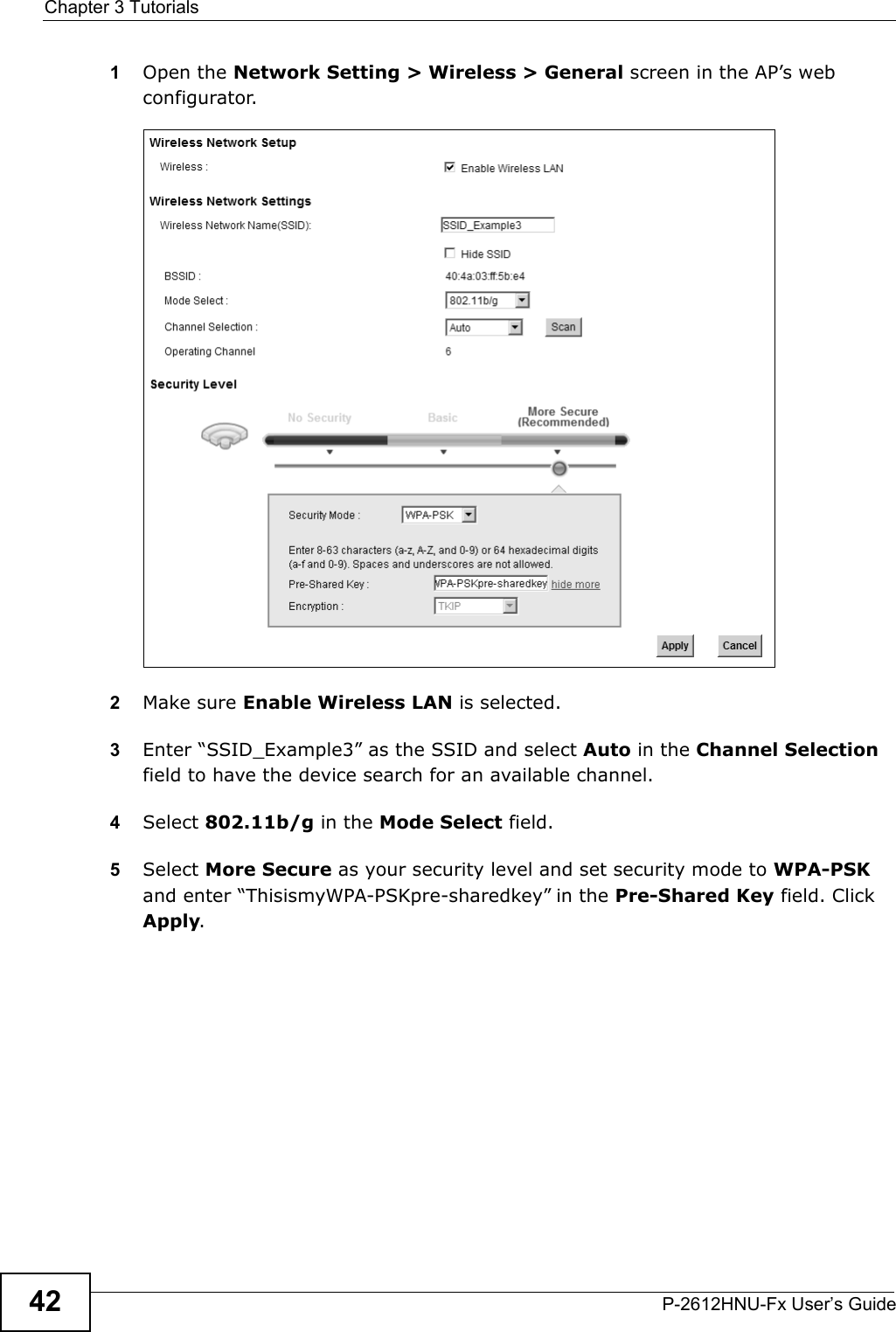
UserManual.wiki
>
ZyXEL Communications
>
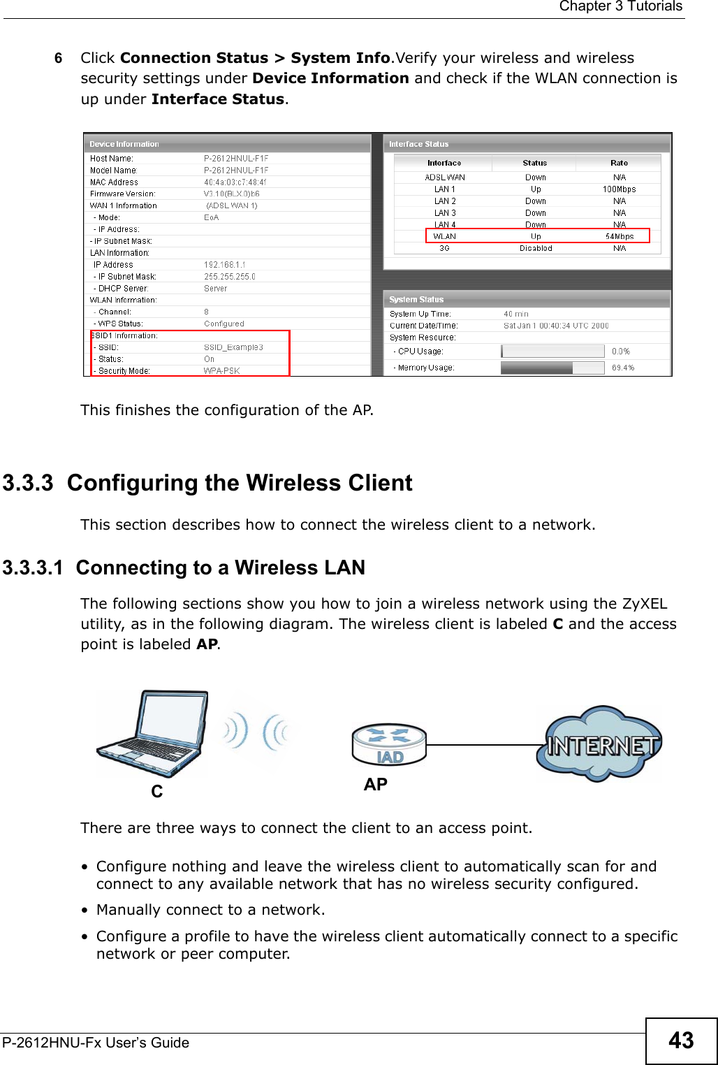
P2612HNUF1F User Manual
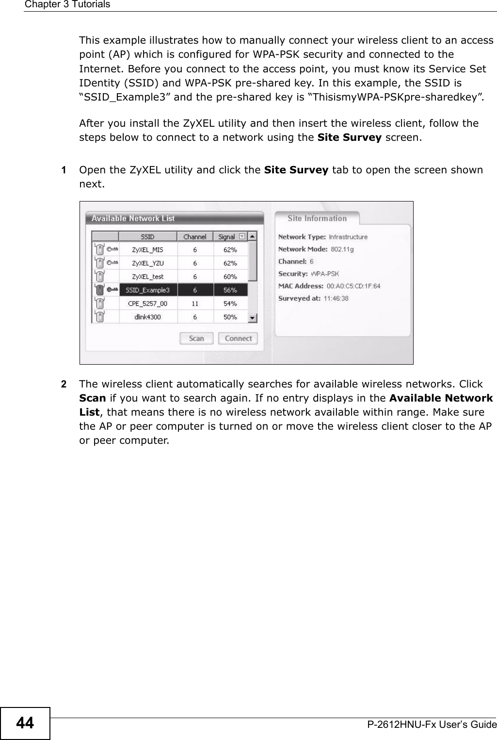
>
Manual Part 1
Contents
1.
Manual
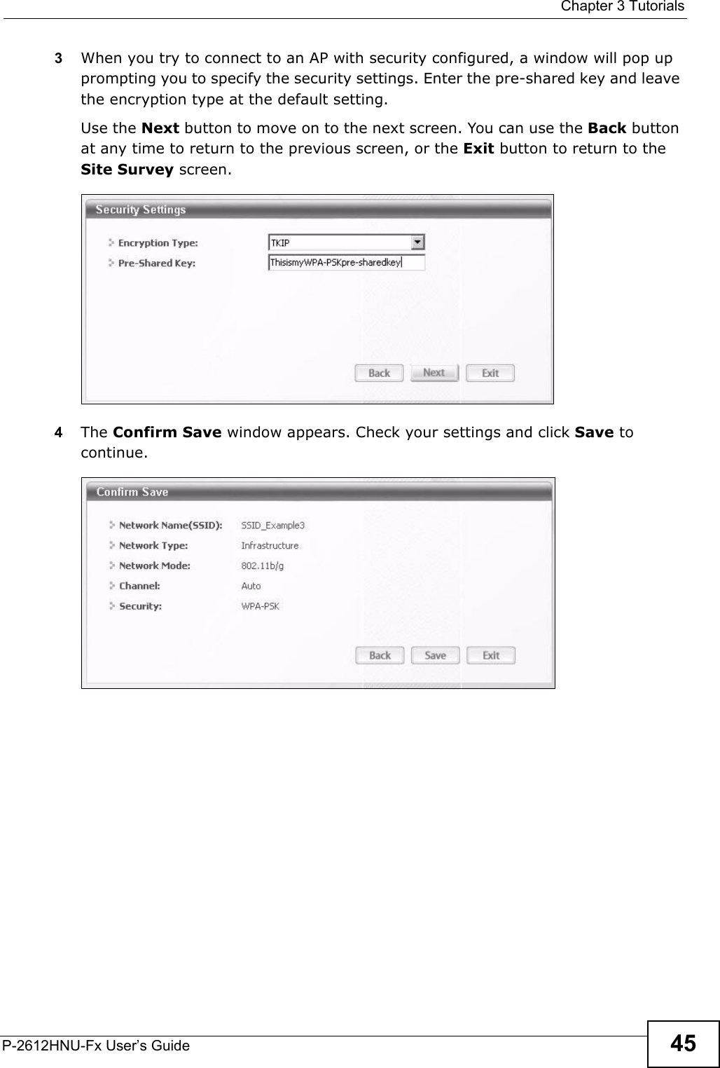
2.
Manual Part 1
3.
Manual Part 2
Manual Part 1
Navigation menu
Upload a User Manual
Namespaces
Wiki Guide
HTML
PDF
Info
Views
User Manual
Discussion / Help
Navigation
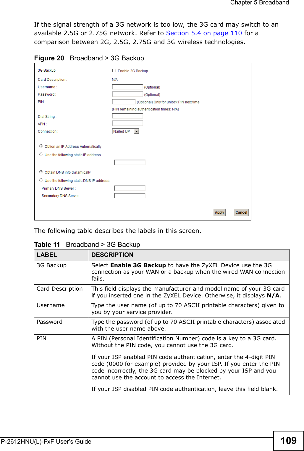
![Document ConventionsP-2612HNU(L)-FxF User’s Guide 5Document ConventionsWarnings and NotesThese are how warnings and notes are shown in this User’s Guide. Warnings tell you about things that could harm you or your device.Note: Notes tell you other important information (for example, other things you may need to configure or helpful tips) or recommendations.Syntax Conventions• The P-2612HNU(L)-FxF may be referred to as the “ZyXEL Device”, the “device”, the “system” or the “product” in this User’s Guide.• Product labels, screen names, field labels and field choices are all in bold font.• A key stroke is denoted by square brackets and uppercase text, for example, [ENTER] means the “enter” or “return” key on your keyboard.• “Enter” means for you to type one or more characters and then press the [ENTER] key. “Select” or “choose” means for you to use one of the predefinedchoices.• A right angle bracket ( > ) within a screen name denotes a mouse click. Forexample, Maintenance > Log > Log Setting means you first click Maintenance in the navigation panel, then the Log sub menu and finally the Log Setting tab to get to that screen.• Units of measurement may denote the “metric” value or the “scientific” value. For example, “k” for kilo may denote “1000” or “1024”, “M” for mega may denote “1000000” or “1048576” and so on.• “e.g.,” is a shorthand for “for instance”, and “i.e.,” means “that is” or “in otherwords”.](https://usermanual.wiki/ZyXEL-Communications/P2612HNUF1F.Manual-Part-1/User-Guide-1960226-Page-5.png)
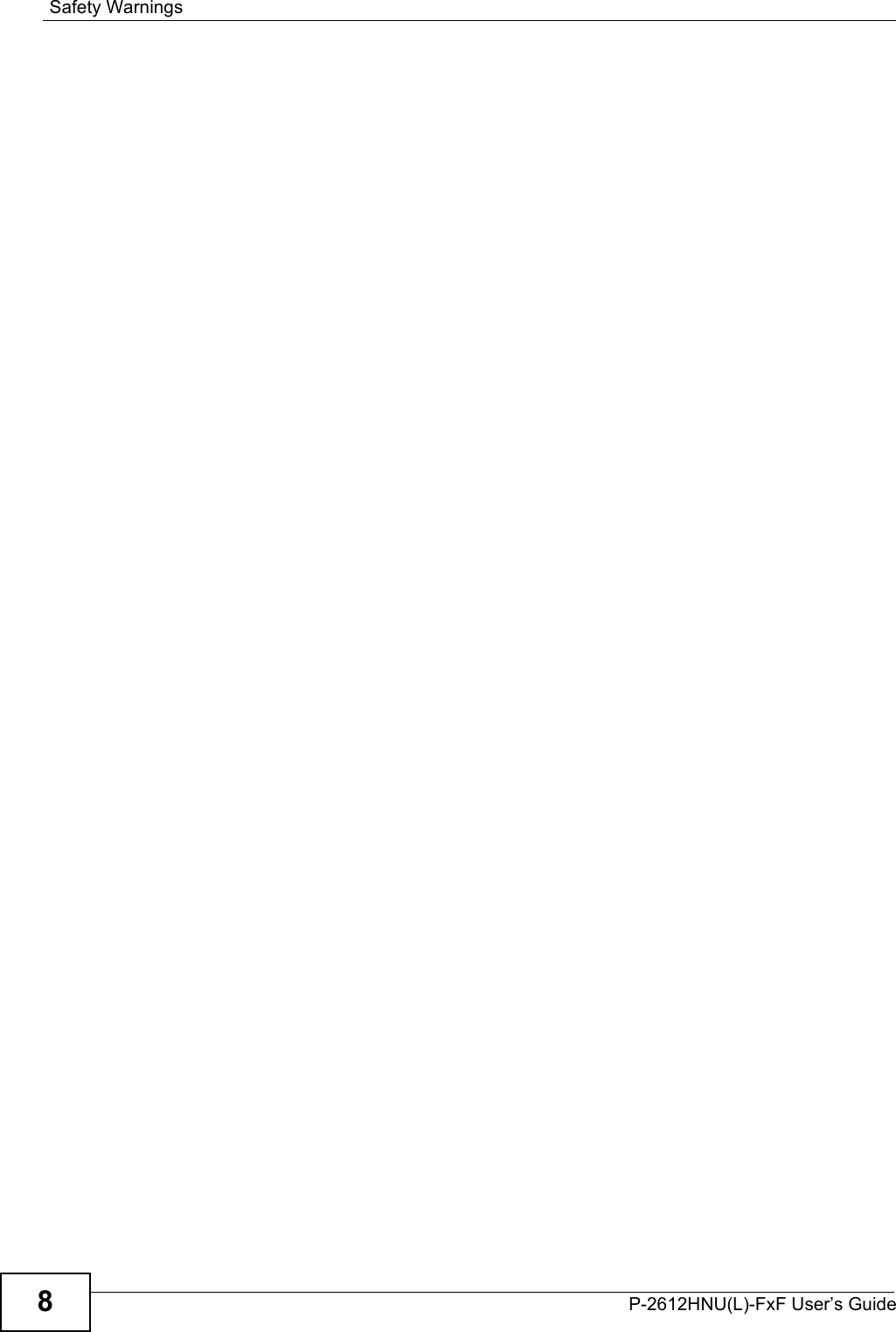
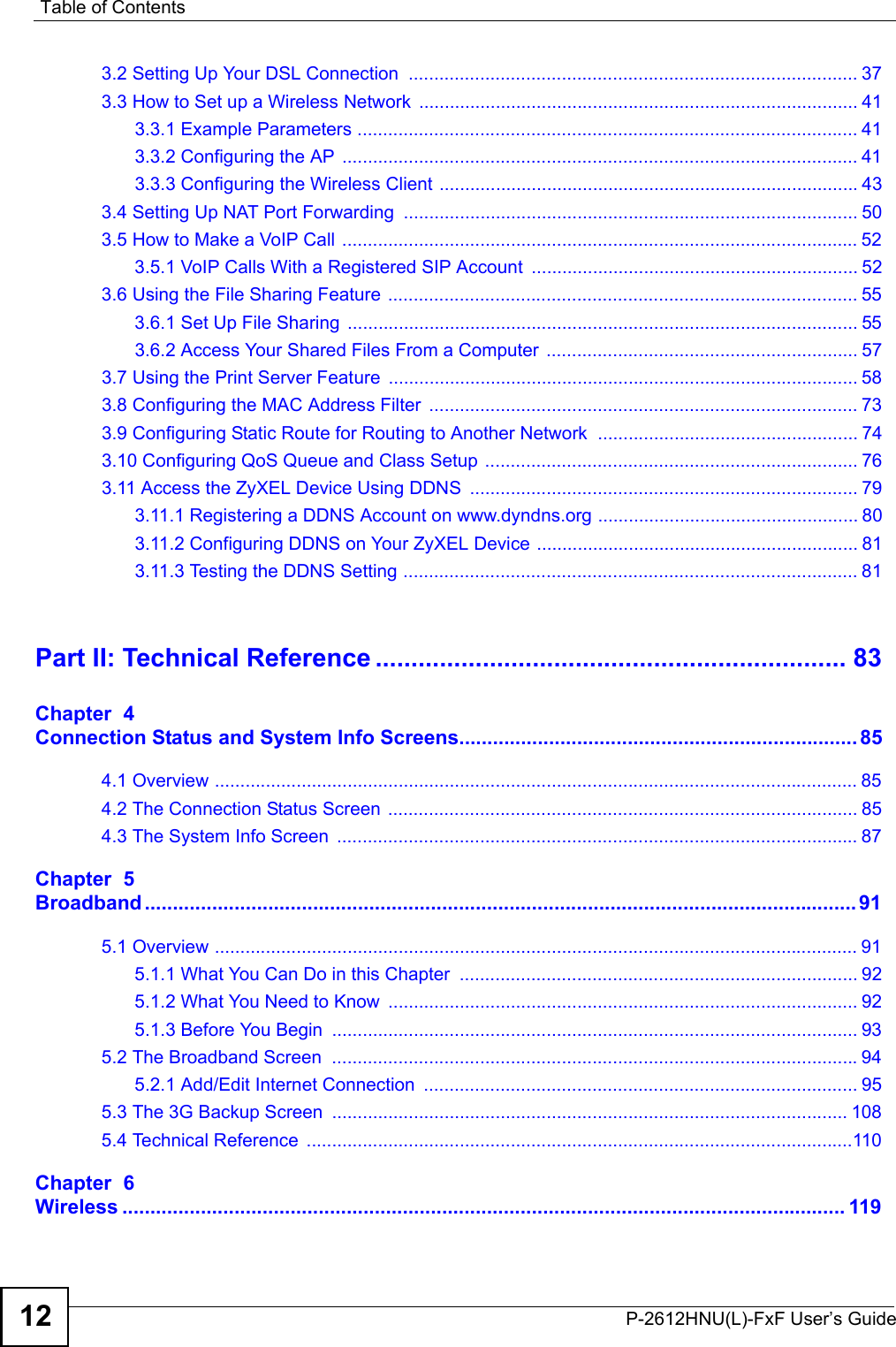


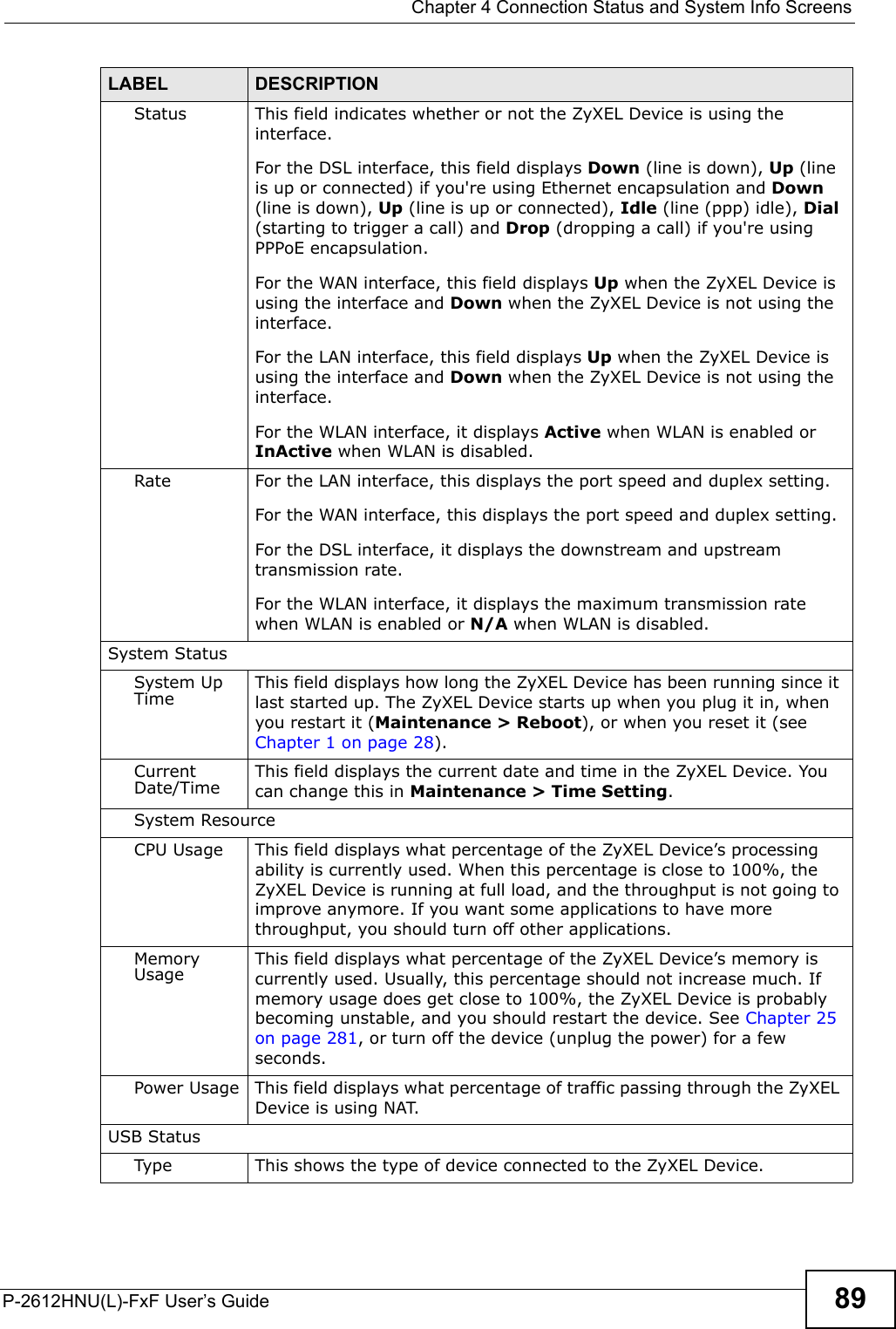
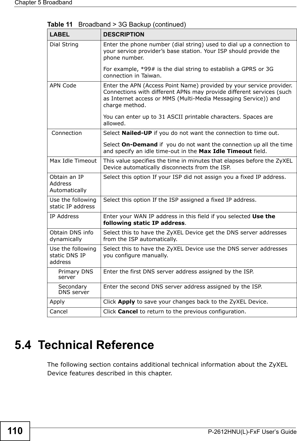
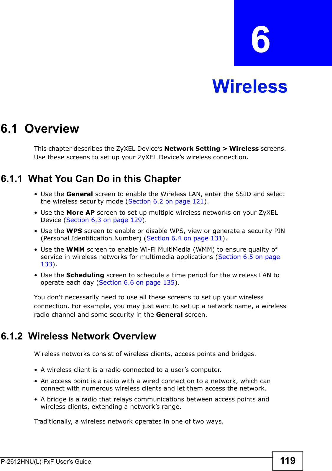
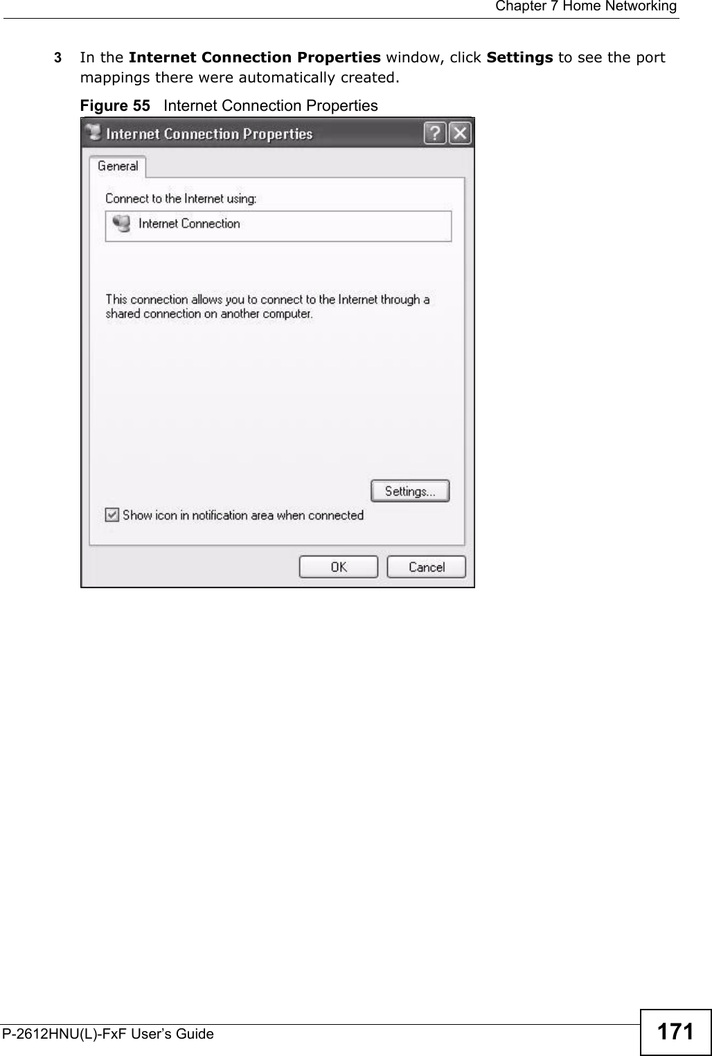
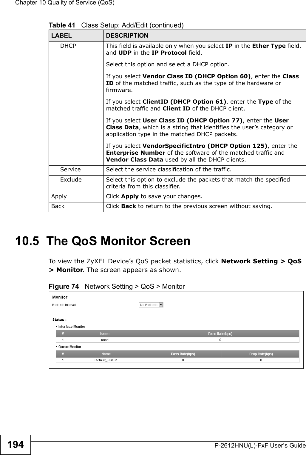
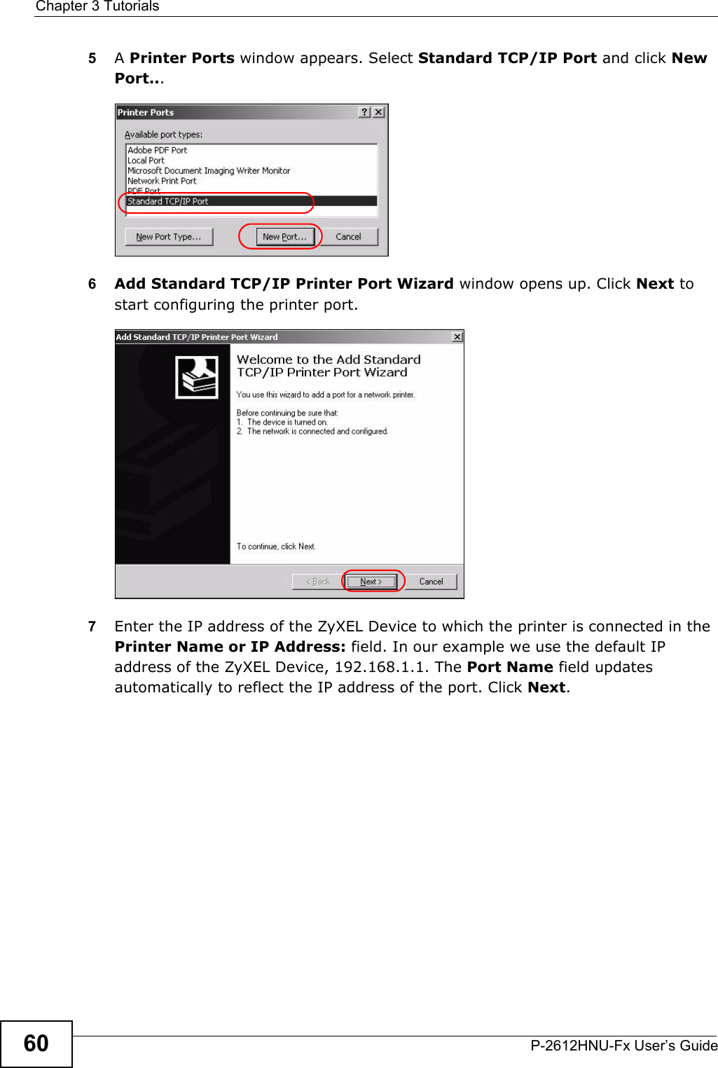
![Chapter 3 TutorialsP-2612HNU-Fx User’s Guide 573You can add a description for the share or leave it blank. The Add Share Directory screen should look like the following.Click Apply to finish.Tutorial: USB Services > File Sharing > Share Configuration4This sets up the file sharing server. You can see the USB storage device listed in the table below.Tutorial: USB Services > File Sharing > Share Configuration (2)3.6.2 Access Your Shared Files From a Computer You can use Windows Explorer to access the file storage devices connected to the ZyXEL Device.Note: The examples in this User’s Guide show you how to use Microsoft’s Windows XP to browse your shared files. Refer to your operating system’sdocumentation for how to browse your file structure. Open Windows Explorer to access Bob’s Share using Windows Explorer browser.In Windows Explorer’s Address bar type a double backslash “\\” followed by the IP address of the ZyXEL Device (the default IP address of the ZyXEL Device is192.168.1.1) and press [ENTER]. The share folder Bob’s_Share is available.File Sharing via Windows Explore rOnce you access Bob’s_Share via your ZyXEL Device, you do not have to reloginunless you restart your computer.](https://usermanual.wiki/ZyXEL-Communications/P2612HNUF1F.Manual-Part-1/User-Guide-1960226-Page-57.png)
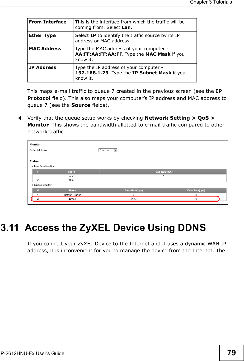
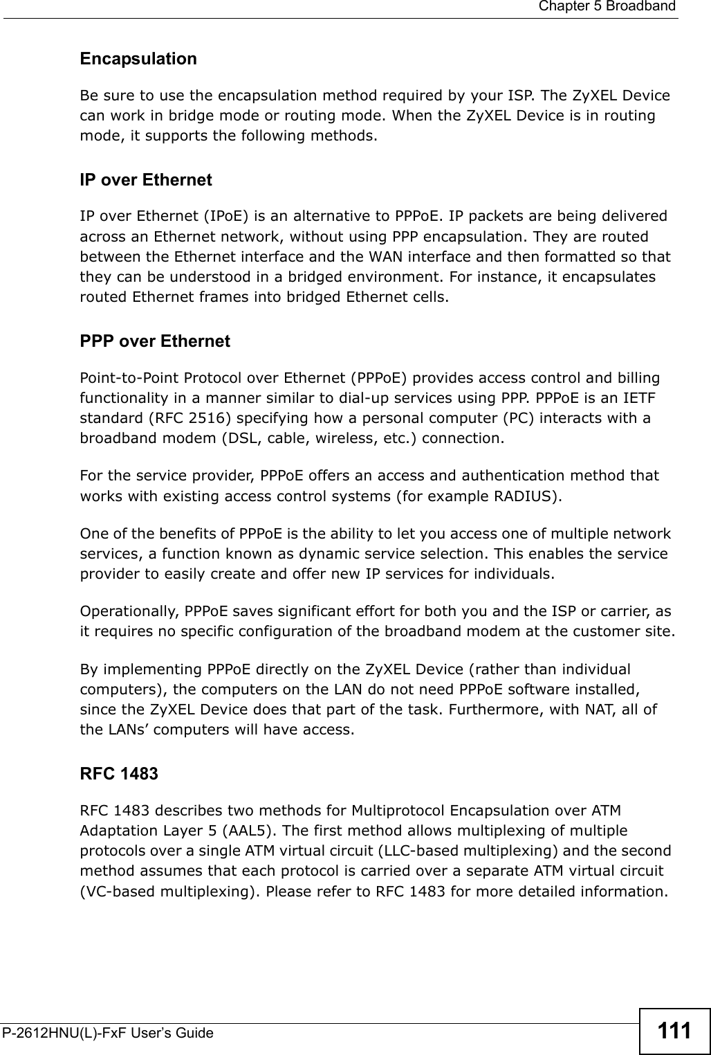
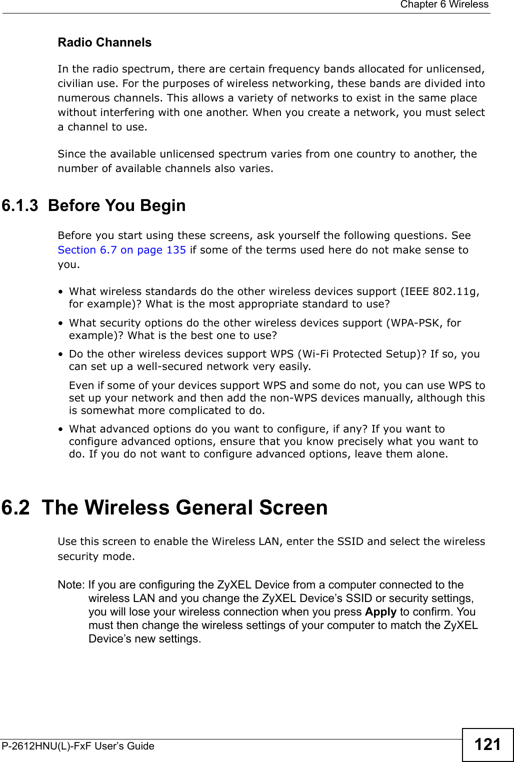
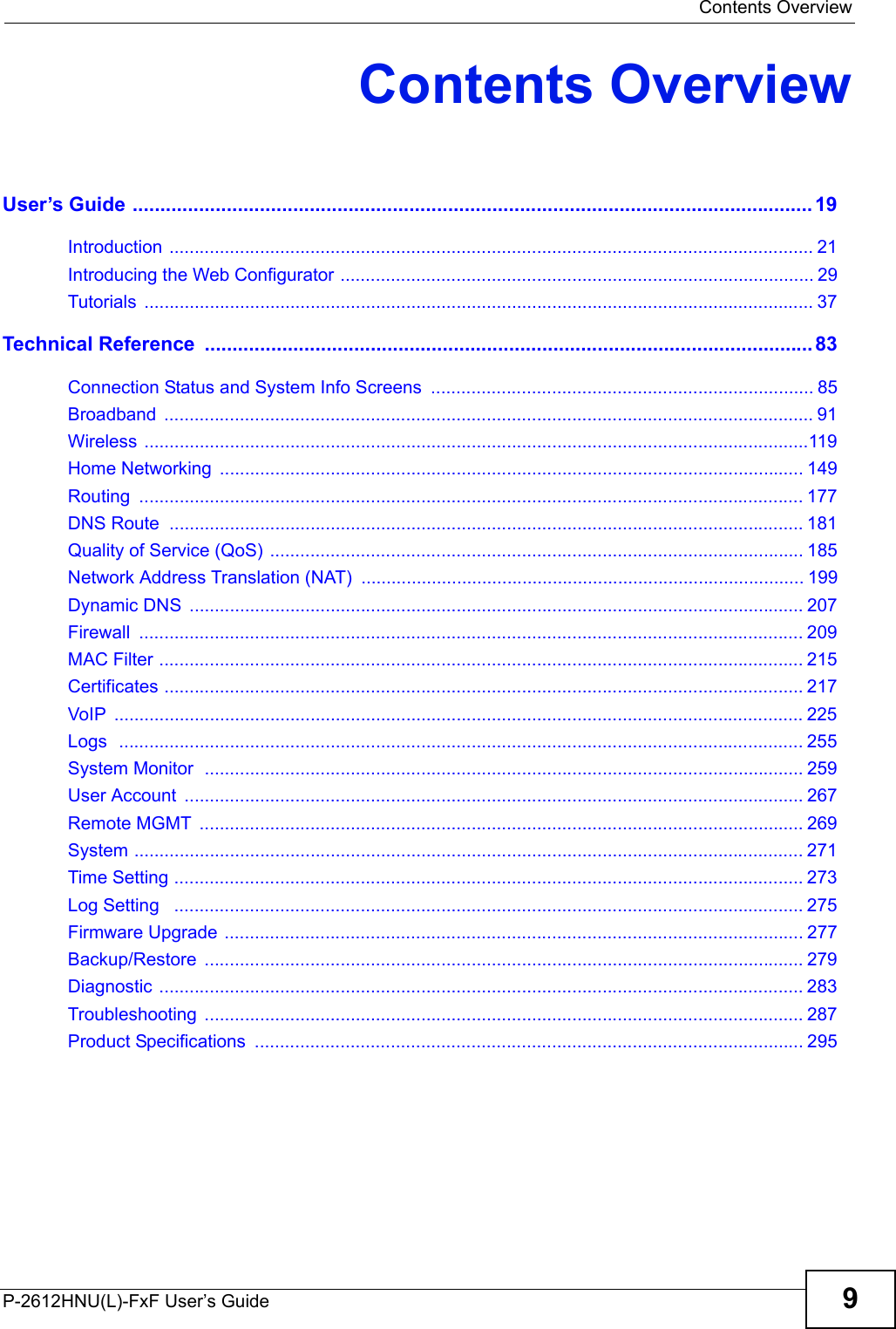
![Chapter 3 TutorialsP-2612HNU-Fx User’s Guide 813.11.2 Configuring DDNS on Your ZyXEL DeviceConfigure the following settings in the Network Setting > DNS screen.• Select Active Dynamic DNS.• Select Dynamic DNS for the DDNS type.• Type zyxelrouter.dyndns.org in the Host Name field.• Enter the user name (UserName1) and password (12345).Click Apply.3.11.3 Testing the DDNS SettingNow you should be able to access the ZyXEL Device from the Internet. To testthis:1Open a web browser on the computer (using the IP address a.b.c.d) that is connected to the Internet.2Type http://zyxelrouter.dyndns.org and press [Enter].3The ZyXEL Device’s login page should appear. You can then log into the ZyXEL Device and manage it.](https://usermanual.wiki/ZyXEL-Communications/P2612HNUF1F.Manual-Part-1/User-Guide-1960226-Page-81.png)