ZyXEL Communications P2612HNUF1F ADSL2+ VoIP IAD User Manual Manual Part 1
ZyXEL Communications Corporation ADSL2+ VoIP IAD Manual Part 1
Contents
- 1. Manual
- 2. Manual Part 1
- 3. Manual Part 2
Manual Part 1
www.zyxel.com
www.zyxel.com
P-2612HNU(L)-FxF
802.11n ADSL2+ VoIP IAD
Copyright © 2013
ZyXEL Communications Corporation
Firmware Version 3.10
Edition 1, 9/2013
Default Login Details
IP Address https://192.168.1.1
User Name Admin account: admin
User account: user
Password Admin account: 1234
User account: 1234
About This User's Guide
P-2612HNU(L)-FxF User’s Guide 3
About This User's Guide
Intended Audience
This manual is intended for people who want to configure the ZyXEL Device using
the web configurator.
Related Documentation
• Quick Start Guide
The Quick Start Guide is designed to help you get up and running right away. It
contains information on setting up your network and configuring for Internet
access.
• Support Disc
Refer to the included CD for support documents.
Documentation Feedback
Send your comments, questions or suggestions to: techwriters@zyxel.com.tw
Thank you!
The Technical Writing Team, ZyXEL Communications Corp.,
6 Innovation Road II, Science-Based Industrial Park, Hsinchu, 30099, Taiwan.
Need More Help?
More help is available at www.zyxel.com.

About This User's Guide
P-2612HNU(L)-FxF User’s Guide
4
• Download Library
Search for the latest product updates and documentation from this link. Read
the Tech Doc Overview to find out how to efficiently use the User Guide, Quick
Start Guide and Command Line Interface Reference Guide in order to better
understand how to use your product.
• Knowledge Base
If you have a specific question about your product, the answer may be here.
This is a collection of answers to previously asked questions about ZyXEL
products.
• Forum
This contains discussions on ZyXEL products. Learn from others who use ZyXEL
products and share your experiences as well.
Customer Support
Should problems arise that cannot be solved by the methods listed above, you
should contact your vendor. If you cannot contact your vendor, then contact a
ZyXEL office for the region in which you bought the device.
See http://www.zyxel.com/web/contact_us.php for contact information. Please
have the following information ready when you contact an office.
• Product model and serial number.
• Warranty Information.
• Date that you received your device.
• Brief description of the problem and the steps you took to solve it.

Document Conventions
P-2612HNU(L)-FxF User’s Guide 5
Document Conventions
Warnings and Notes
These are how warnings and notes are shown in this User’s Guide.
Warnings tell you about things that could harm you or your device.
Note: Notes tell you other important information (for example, other things you may
need to configure or helpful tips) or recommendations.
Syntax Conventions
• The P-2612HNU(L)-FxF may be referred to as the “ZyXEL Device”, the “device”,
the “system” or the “product” in this User’s Guide.
• Product labels, screen names, field labels and field choices are all in bold font.
• A key stroke is denoted by square brackets and uppercase text, for example,
[ENTER] means the “enter” or “return” key on your keyboard.
• “Enter” means for you to type one or more characters and then press the
[ENTER] key. “Select” or “choose” means for you to use one of the predefined
choices.
• A right angle bracket ( > ) within a screen name denotes a mouse click. For
example, Maintenance > Log > Log Setting means you first click
Maintenance in the navigation panel, then the Log sub menu and finally the
Log Setting tab to get to that screen.
• Units of measurement may denote the “metric” value or the “scientific” value.
For example, “k” for kilo may denote “1000” or “1024”, “M” for mega may
denote “1000000” or “1048576” and so on.
• “e.g.,” is a shorthand for “for instance”, and “i.e.,” means “that is” or “in other
words”.
Document Conventions
P-2612HNU(L)-FxF User’s Guide
6
Icons Used in Figures
Figures in this User’s Guide may use the following generic icons. The ZyXEL Device
icon is not an exact representation of your device.
ZyXEL Device Computer Notebook computer
Server Firewall Telephone
Router Switch

Safety Warnings
P-2612HNU(L)-FxF User’s Guide 7
Safety Warnings
• Do NOT use this product near water, for example, in a wet basement or near a swimming
pool.
• Do NOT expose your device to dampness, dust or corrosive liquids.
• Do NOT store things on the device.
• Do NOT install, use, or service this device during a thunderstorm. There is a remote risk
of electric shock from lightning.
• Connect ONLY suitable accessories to the device.
• Do NOT open the device or unit. Opening or removing covers can expose you to
dangerous high voltage points or other risks. ONLY qualified service personnel should
service or disassemble this device. Please contact your vendor for further information.
• Make sure to connect the cables to the correct ports.
• Place connecting cables carefully so that no one will step on them or stumble over them.
• Always disconnect all cables from this device before servicing or disassembling.
• Use ONLY an appropriate power adaptor or cord for your device.
• Connect the power adaptor or cord to the right supply voltage (for example, 110V AC in
North America or 230V AC in Europe).
• Do NOT allow anything to rest on the power adaptor or cord and do NOT place the
product where anyone can walk on the power adaptor or cord.
• Do NOT use the device if the power adaptor or cord is damaged as it might cause
electrocution.
• If the power adaptor or cord is damaged, remove it from the device and the power
source.
• Do NOT attempt to repair the power adaptor or cord. Contact your local vendor to order a
new one.
• Do not use the device outside, and make sure all the connections are indoors. There is a
remote risk of electric shock from lightning.
• Do NOT obstruct the device ventilation slots, as insufficient airflow may harm your
device.
• Use only No. 26 AWG (American Wire Gauge) or larger telecommunication line cord.
• If you wall mount your device, make sure that no electrical lines, gas or water pipes will
be damaged.
• This CPE is indoor use only. (Utilisation intérieure exclusivement.)
Your product is marked with this symbol, which is known as the WEEE mark. WEEE
stands for Waste Electronics and Electrical Equipment. It means that used electrical
and electronic products should not be mixed with general waste. Used electrical and
electronic equipment should be treated separately.

Safety Warnings
P-2612HNU(L)-FxF User’s Guide
8

Contents Overview
P-2612HNU(L)-FxF User’s Guide 9
Contents Overview
User’s Guide ...........................................................................................................................19
Introduction ................................................................................................................................ 21
Introducing the Web Configurator .............................................................................................. 29
Tutorials ..................................................................................................................................... 37
Technical Reference .............................................................................................................. 83
Connection Status and System Info Screens ............................................................................ 85
Broadband ................................................................................................................................. 91
Wireless ....................................................................................................................................119
Home Networking .................................................................................................................... 149
Routing .................................................................................................................................... 177
DNS Route .............................................................................................................................. 181
Quality of Service (QoS) .......................................................................................................... 185
Network Address Translation (NAT) ........................................................................................ 199
Dynamic DNS .......................................................................................................................... 207
Firewall .................................................................................................................................... 209
MAC Filter ................................................................................................................................ 215
Certificates ............................................................................................................................... 217
VoIP ......................................................................................................................................... 225
Logs ........................................................................................................................................ 255
System Monitor ....................................................................................................................... 259
User Account ........................................................................................................................... 267
Remote MGMT ........................................................................................................................ 269
System ..................................................................................................................................... 271
Time Setting ............................................................................................................................. 273
Log Setting ............................................................................................................................. 275
Firmware Upgrade ................................................................................................................... 277
Backup/Restore ....................................................................................................................... 279
Diagnostic ................................................................................................................................ 283
Troubleshooting ....................................................................................................................... 287
Product Specifications ............................................................................................................. 295

Contents Overview
P-2612HNU(L)-FxF User’s Guide
10

Table of Contents
P-2612HNU(L)-FxF User’s Guide 11
Table of Contents
About This User's Guide .......................................................................................................... 3
Document Conventions............................................................................................................5
Safety Warnings........................................................................................................................7
Contents Overview ...................................................................................................................9
Table of Contents.................................................................................................................... 11
Part I: User’s Guide................................................................................ 19
Chapter 1
Introduction ............................................................................................................................. 21
1.1 Overview .............................................................................................................................. 21
1.2 Applications for the ZyXEL Device ...................................................................................... 22
1.2.1 Internet Access .......................................................................................................... 22
1.2.2 VoIP Features ............................................................................................................ 23
1.2.3 ZyXEL Device’s USB Support .................................................................................... 24
1.2.4 Wireless Connection .................................................................................................. 24
1.3 The WPS/WLAN Button ...................................................................................................... 25
1.4 Ways to Manage the ZyXEL Device .................................................................................... 25
1.5 Good Habits for Managing the ZyXEL Device ..................................................................... 26
1.6 LEDs (Lights) ....................................................................................................................... 26
1.7 The RESET Button .............................................................................................................. 28
Chapter 2
Introducing the Web Configurator ........................................................................................ 29
2.1 Overview .............................................................................................................................. 29
2.1.1 Accessing the Web Configurator ................................................................................ 29
2.2 The Web Configurator Layout .............................................................................................. 32
2.2.1 Title Bar ...................................................................................................................... 32
2.2.2 Main Window .............................................................................................................. 33
2.2.3 Navigation Panel ........................................................................................................ 33
Chapter 3
Tutorials ................................................................................................................................... 37
3.1 Overview .............................................................................................................................. 37

Table of Contents
P-2612HNU(L)-FxF User’s Guide
12
3.2 Setting Up Your DSL Connection ........................................................................................ 37
3.3 How to Set up a Wireless Network ...................................................................................... 41
3.3.1 Example Parameters .................................................................................................. 41
3.3.2 Configuring the AP ..................................................................................................... 41
3.3.3 Configuring the Wireless Client .................................................................................. 43
3.4 Setting Up NAT Port Forwarding ......................................................................................... 50
3.5 How to Make a VoIP Call ..................................................................................................... 52
3.5.1 VoIP Calls With a Registered SIP Account ................................................................ 52
3.6 Using the File Sharing Feature ............................................................................................ 55
3.6.1 Set Up File Sharing .................................................................................................... 55
3.6.2 Access Your Shared Files From a Computer ............................................................. 57
3.7 Using the Print Server Feature ............................................................................................ 58
3.8 Configuring the MAC Address Filter .................................................................................... 73
3.9 Configuring Static Route for Routing to Another Network ................................................... 74
3.10 Configuring QoS Queue and Class Setup ......................................................................... 76
3.11 Access the ZyXEL Device Using DDNS ............................................................................ 79
3.11.1 Registering a DDNS Account on www.dyndns.org ................................................... 80
3.11.2 Configuring DDNS on Your ZyXEL Device ............................................................... 81
3.11.3 Testing the DDNS Setting ......................................................................................... 81
Part II: Technical Reference .................................................................. 83
Chapter 4
Connection Status and System Info Screens.......................................................................85
4.1 Overview .............................................................................................................................. 85
4.2 The Connection Status Screen ............................................................................................ 85
4.3 The System Info Screen ...................................................................................................... 87
Chapter 5
Broadband ............................................................................................................................... 91
5.1 Overview .............................................................................................................................. 91
5.1.1 What You Can Do in this Chapter .............................................................................. 92
5.1.2 What You Need to Know ............................................................................................ 92
5.1.3 Before You Begin ....................................................................................................... 93
5.2 The Broadband Screen ....................................................................................................... 94
5.2.1 Add/Edit Internet Connection ..................................................................................... 95
5.3 The 3G Backup Screen ..................................................................................................... 108
5.4 Technical Reference ...........................................................................................................110
Chapter 6
Wireless ................................................................................................................................. 119

Table of Contents
P-2612HNU(L)-FxF User’s Guide 13
6.1 Overview .............................................................................................................................119
6.1.1 What You Can Do in this Chapter .............................................................................119
6.1.2 Wireless Network Overview ......................................................................................119
6.1.3 Before You Begin ..................................................................................................... 121
6.2 The Wireless General Screen .......................................................................................... 121
6.2.1 No Security ............................................................................................................... 123
6.2.2 Basic (Static WEP/Shared WEP Encryption) ........................................................... 124
6.2.3 More Secure (WPA(2)-PSK) .................................................................................... 126
6.2.4 WPA(2) Authentication ............................................................................................. 127
6.3 The More AP Screen ......................................................................................................... 129
6.3.1 Edit More AP ............................................................................................................ 130
6.4 The WPS Screen ............................................................................................................... 131
6.5 The WMM Screen .............................................................................................................. 133
6.6 Scheduling Screen ........................................................................................................... 135
6.7 Technical Reference .......................................................................................................... 135
6.7.1 Additional Wireless Terms ........................................................................................ 136
6.7.2 Wireless Security Overview ..................................................................................... 136
6.7.3 Signal Problems ....................................................................................................... 139
6.7.4 BSS .......................................................................................................................... 139
6.7.5 MBSSID ................................................................................................................... 140
6.7.6 WiFi Protected Setup (WPS) .................................................................................... 141
Chapter 7
Home Networking .................................................................................................................149
7.1 Overview ............................................................................................................................ 149
7.1.1 What You Can Do in this Chapter ............................................................................ 149
7.1.2 What You Need To Know ......................................................................................... 150
7.2 The LAN Setup Screen ...................................................................................................... 153
7.3 The Static DHCP Screen ................................................................................................... 154
7.3.1 Before You Begin ..................................................................................................... 154
7.4 The UPnP Screen .............................................................................................................. 156
7.5 The File Sharing Screen .................................................................................................... 157
7.5.1 Before You Begin ..................................................................................................... 157
7.5.2 Add/Edit File Sharing ............................................................................................... 159
7.6 The Printer Server Screen ................................................................................................. 160
7.6.1 Before You Begin ..................................................................................................... 160
7.7 Technical Reference .......................................................................................................... 161
7.8 Installing UPnP in Windows Example ................................................................................ 165
7.9 Using UPnP in Windows XP Example ............................................................................... 169
Chapter 8
Routing .................................................................................................................................. 177
8.1 Overview ........................................................................................................................... 177

Table of Contents
P-2612HNU(L)-FxF User’s Guide
14
8.2 Configuring Static Route .................................................................................................... 178
8.2.1 Add/Edit Static Route ............................................................................................. 179
Chapter 9
DNS Route .............................................................................................................................181
9.1 Overview ............................................................................................................................ 181
9.1.1 What You Can Do in this Chapter ............................................................................ 182
9.2 The DNS Route Screen ..................................................................................................... 182
9.2.1 Add/Edit DNS Route Edit ........................................................................................ 183
Chapter 10
Quality of Service (QoS).......................................................................................................185
10.1 Overview .......................................................................................................................... 185
10.1.1 What You Can Do in this Chapter .......................................................................... 185
10.1.2 What You Need to Know ........................................................................................ 186
10.2 The QoS General Screen ............................................................................................... 186
10.3 The Queue Setup Screen ................................................................................................ 188
10.3.1 Add/Edit a QoS Queue .......................................................................................... 189
10.4 The Class Setup Screen ................................................................................................ 190
10.4.1 Add/Edit QoS Class .............................................................................................. 191
10.5 The QoS Monitor Screen ................................................................................................ 194
10.6 QoS Technical Reference ................................................................................................ 195
10.6.1 IEEE 802.1Q Tag ................................................................................................... 195
10.6.2 IP Precedence ........................................................................................................ 196
10.6.3 DiffServ ................................................................................................................. 196
Chapter 11
Network Address Translation (NAT).................................................................................... 199
11.1 Overview ......................................................................................................................... 199
11.1.1 What You Can Do in this Chapter ........................................................................... 199
11.1.2 What You Need To Know ........................................................................................ 199
11.2 The Port Forwarding Screen ........................................................................................... 200
11.2.1 The Port Forwarding Screen .................................................................................. 201
11.2.2 The Port Forwarding Edit Screen ........................................................................... 202
11.3 The Sessions Screen ....................................................................................................... 203
11.4 Technical Reference ........................................................................................................ 204
11.4.1 NAT Definitions ....................................................................................................... 204
11.4.2 What NAT Does ...................................................................................................... 205
11.4.3 How NAT Works ..................................................................................................... 205
Chapter 12
Dynamic DNS ........................................................................................................................207
12.1 Overview ......................................................................................................................... 207

Table of Contents
P-2612HNU(L)-FxF User’s Guide 15
12.1.1 What You Need To Know ....................................................................................... 207
12.2 The Dynamic DNS Screen .............................................................................................. 208
Chapter 13
Firewall................................................................................................................................... 209
13.1 Overview .......................................................................................................................... 209
13.1.1 What You Can Do in this Chapter .......................................................................... 209
13.1.2 What You Need to Know ........................................................................................ 210
13.2 The General Screen ........................................................................................................211
13.3 The Services Screen ........................................................................................................211
13.4 Firewall Technical Reference ........................................................................................... 213
13.4.1 Guidelines For Enhancing Security With Your Firewall .......................................... 213
13.4.2 Security Considerations ......................................................................................... 213
Chapter 14
MAC Filter..............................................................................................................................215
14.1 Overview .......................................................................................................................... 215
14.1.1 What You Need to Know ........................................................................................ 215
14.2 The MAC Filter Screen .................................................................................................... 216
Chapter 15
Certificates ............................................................................................................................ 217
15.1 Overview .......................................................................................................................... 217
15.1.1 What You Can Do in this Chapter .......................................................................... 217
15.1.2 What You Need to Know ........................................................................................ 217
15.1.3 Verifying a Certificate ............................................................................................. 219
15.2 Local Certificates ............................................................................................................. 220
15.3 Trusted CA ..................................................................................................................... 222
15.4 Trusted CA Import ......................................................................................................... 223
15.5 View Certificate ................................................................................................................ 224
Chapter 16
VoIP ........................................................................................................................................ 225
16.1 Overview .......................................................................................................................... 225
16.1.1 What You Can Do in this Chapter .......................................................................... 225
16.1.2 What You Need to Know ........................................................................................ 226
16.1.3 Before You Begin ................................................................................................... 227
16.2 The SIP Service Provider Screen ................................................................................... 227
16.3 The SIP Account Screen ................................................................................................. 231
16.3.1 Add/Edit SIP Account ............................................................................................. 233
16.4 The SIP Common Screen ................................................................................................ 236
16.5 Multiple SIP Accounts ...................................................................................................... 236
16.5.1 Outgoing Calls ........................................................................................................ 237

Table of Contents
P-2612HNU(L)-FxF User’s Guide
16
16.5.2 Incoming Calls ........................................................................................................ 238
16.6 The Phone Device Screen .............................................................................................. 239
16.6.1 Edit Phone Device .................................................................................................. 240
16.7 The Region Screen ......................................................................................................... 241
16.8 The Call Rule Screen ...................................................................................................... 241
16.9 The FXO Screen (“L” Models Only) ................................................................................. 243
16.10 Technical Reference ...................................................................................................... 244
16.10.1 VoIP ...................................................................................................................... 244
16.10.2 SIP ...................................................................................................................... 244
16.10.3 Quality of Service (QoS) ...................................................................................... 250
16.10.4 Phone Services Overview .................................................................................... 251
Chapter 17
Logs ......................................................................................................................................255
17.1 Overview ......................................................................................................................... 255
17.1.1 What You Can Do in this Chapter .......................................................................... 255
17.2 The Phone Log Screen .................................................................................................... 255
17.3 The VoIP Call History Screen .......................................................................................... 256
Chapter 18
System Monitor ....................................................................................................................259
18.1 Overview .......................................................................................................................... 259
18.1.1 What You Can Do in this Chapter .......................................................................... 259
18.2 The WAN Status Screen .................................................................................................. 260
18.3 The LAN Status Screen ................................................................................................... 261
18.4 The NAT Status Screen ................................................................................................... 262
18.5 The 3G Backup Status Screen ........................................................................................ 262
18.6 The VoIP Status Screen .................................................................................................. 263
Chapter 19
User Account.........................................................................................................................267
19.1 Overview .......................................................................................................................... 267
19.2 The User Account Screen ............................................................................................... 267
Chapter 20
Remote MGMT....................................................................................................................... 269
20.1 Overview .......................................................................................................................... 269
20.1.1 What You Need to Know ........................................................................................ 269
20.2 The Remote MGMT Screen ............................................................................................ 270
Chapter 21
System ................................................................................................................................... 271
21.1 Overview .......................................................................................................................... 271

Table of Contents
P-2612HNU(L)-FxF User’s Guide 17
21.1.1 What You Need to Know ........................................................................................ 271
21.2 The System Screen ......................................................................................................... 271
Chapter 22
Time Setting .......................................................................................................................... 273
22.1 Overview .......................................................................................................................... 273
22.2 The Time Setting Screen ................................................................................................ 273
Chapter 23
Log Setting ...........................................................................................................................275
23.1 Overview ......................................................................................................................... 275
23.2 The Log Setting Screen ................................................................................................... 275
Chapter 24
Firmware Upgrade ................................................................................................................277
24.1 Overview .......................................................................................................................... 277
24.2 The Firmware Upgrade Screen ....................................................................................... 277
Chapter 25
Backup/Restore..................................................................................................................... 279
25.1 Overview .......................................................................................................................... 279
25.2 The Backup/Restore Screen ........................................................................................... 279
25.3 The Reboot Screen ......................................................................................................... 281
Chapter 26
Diagnostic.............................................................................................................................. 283
26.1 Overview .......................................................................................................................... 283
26.1.1 What You Can Do in this Chapter .......................................................................... 283
26.2 The Ping Screen .............................................................................................................. 283
26.3 The DSL Line Screen ...................................................................................................... 284
Chapter 27
Troubleshooting.................................................................................................................... 287
27.1 Overview .......................................................................................................................... 287
27.2 Power, Hardware Connections, and LEDs ...................................................................... 287
27.3 ZyXEL Device Access and Login .................................................................................... 288
27.4 Internet Access ................................................................................................................ 290
27.5 Wireless Internet Access ................................................................................................. 292
27.6 Phone Calls and VoIP ...................................................................................................... 293
27.7 USB Device Connection .................................................................................................. 294
27.8 UPnP ............................................................................................................................... 294
Chapter 28
Product Specifications .........................................................................................................295

Table of Contents
P-2612HNU(L)-FxF User’s Guide
18
Appendix A IP Addresses and Subnetting ...........................................................................305
Appendix B Setting Up Your Computer’s IP Address...........................................................317
Appendix C Pop-up Windows, JavaScript and Java Permissions........................................347
Appendix D Wireless LANs .................................................................................................. 357
Appendix E Common Services............................................................................................. 381
Appendix F Open Software Announcements ....................................................................... 385
Appendix G Legal Information.............................................................................................. 409
Index....................................................................................................................................... 411

19
PART I
User’s Guide

20

P-2612HNU(L)-FxF User’s Guide 21
CHAPTER 1
Introduction
1.1 Overview
The ZyXEL Device is an ADSL2+ Integrated Access Device (IAD) that combines an
ADSL2+ router with Voice over IP (VoIP) communication capabilities to allow you
to use a traditional analog telephone to make Internet calls. By integrating DSL
and NAT, you are provided with ease of installation and high-speed, shared
Internet access. The ZyXEL Device is also a complete security solution with a
robust firewall.
Please refer to the following description of the product name format.
• “H” denotes an integrated 4-port hub (switch).
• “N” denotes wireless functionality, including 802.11n mode. There is an
embedded mini-PCI module for IEEE 802.11 b/g/n wireless LAN connectivity.
• “U” denotes a USB port used to set up a 3G WAN connection via a 3G wireless
card or share files via a USB memory stick or a USB hard drive. The ZyXEL
Device can function as a print server with an USB printer connected.
• “L” denotes the PSTN (Public Switched Telephone Network) line feature. The
PSTN line lets you have VoIP phone service and PSTN phone service at the same
time. All PSTN line features documented in this user’s guide refer to the “L”
models only.
When the ZyXEL Device does not have power, only the phone
connected to the PHONE port 1 can be used for making calls.
Ensure you know which phone this is, so that in case of
emergency you can make outgoing calls.
• Models ending in “1”, for example P-2612HNU(L)-F1, denote a device that works
over the analog telephone system, POTS (Plain Old Telephone Service). Models
ending in “3” denote a device that works over ISDN (Integrated Services Digital
Network) or T-ISDN (UR-2).
Only use firmware for your ZyXEL Device’s specific model. Refer
to the label on the bottom of your ZyXEL Device.
See the chapter on product specifications for a full list of features.
Chapter 1 Introduction
P-2612HNU(L)-FxF User’s Guide
22
1.2 Applications for the ZyXEL Device
Here are some example uses for which the ZyXEL Device is well suited.
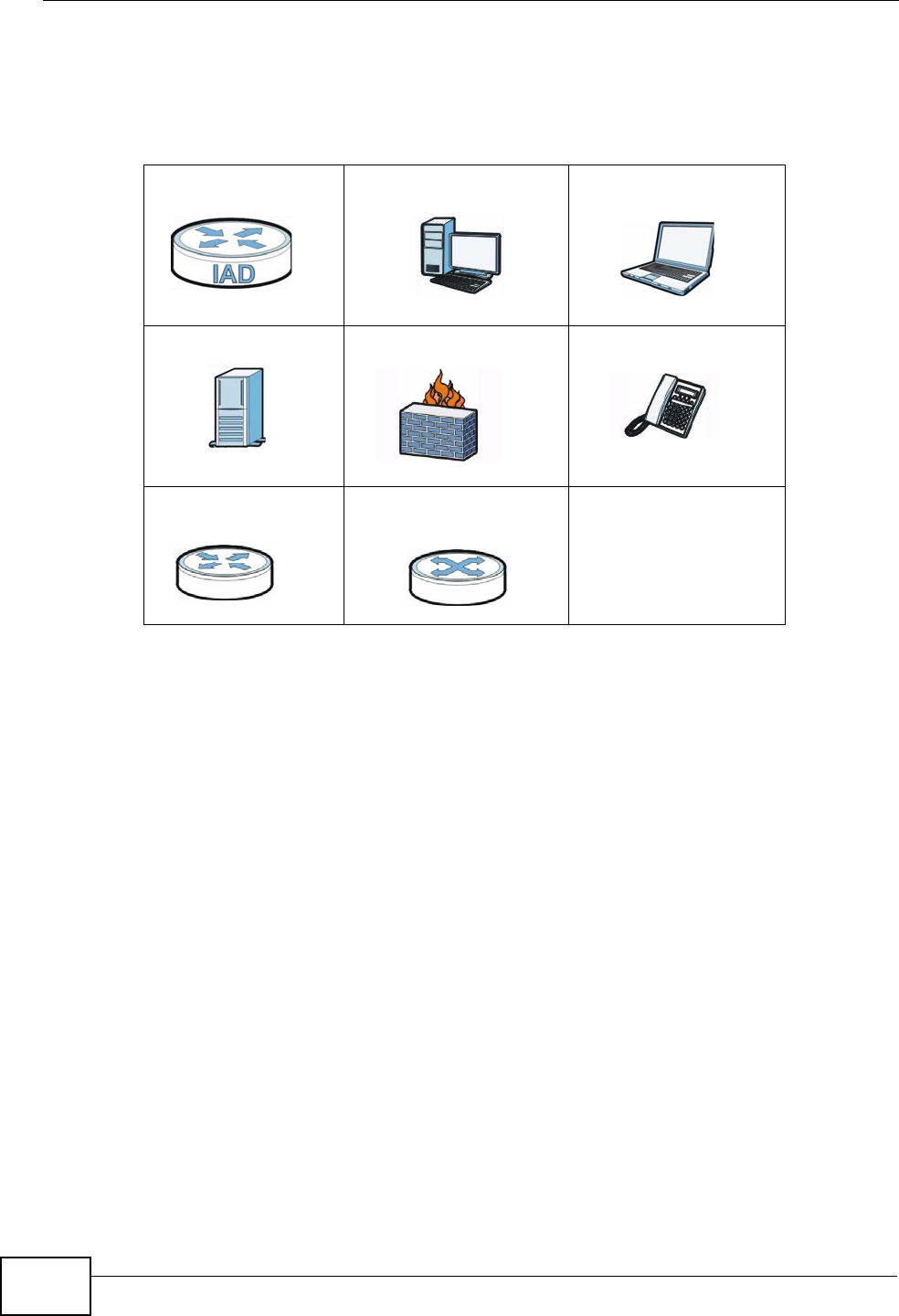
1.2.1 Internet Access
Your ZyXEL Device provides shared Internet access by connecting the DSL port to
the DSL or MODEM jack on a splitter or your telephone jack. Computers can
connect to the ZyXEL Device’s LAN ports (or wirelessly). You can have multiple
WAN services over one ADSL or Ethernet line. The ZyXEL Device cannot work in
ADSL and Ethernet mode at the same time.
Figure 1 ZyXEL Device’s Internet Access Application
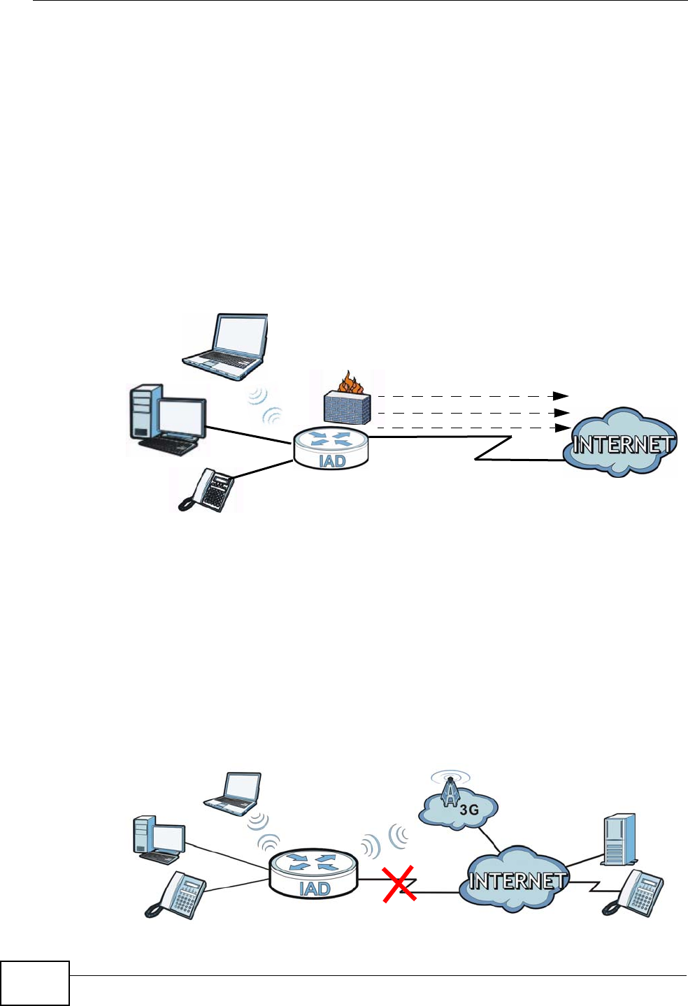
1.2.1.1 3G WAN
The USB port allows you to wirelessly connect to a 3G network to get Internet
access by attaching a 3G wireless card. You must leave the DSL or Ethernet WAN
port unconnected and attached a 3G wireless card to use 3G as your WAN. You
can also have the ZyXEL Device use the 3G WAN connection as a backup. That
means the ZyXEL Device switches to the 3G wireless WAN connection after the
wired DSL or Ethernet WAN connection fails. The ZyXEL Device automatically
changes back to use the wired DSL or Ethernet WAN connection when it is
available.
Figure 2 Internet Access Application: 3G WAN
LAN
PPPoE
IPoE
Bridging
WAN
ADSL/Ethernet
Chapter 1 Introduction
P-2612HNU(L)-FxF User’s Guide 23
You can also configure firewall on the ZyXEL Device for secure Internet access.
When the firewall is on, all incoming traffic from the Internet to your network is
blocked unless it is initiated from your network. This means that probes from the
outside to your network are not allowed, but you can safely browse the Internet
and download files.
Use QoS to efficiently manage traffic on your network by giving priority to certain
types of traffic and/or to particular computers. For example, you could make sure
that the ZyXEL Device gives voice over Internet calls high priority, and/or limit
bandwidth devoted to the boss’s excessive file downloading.
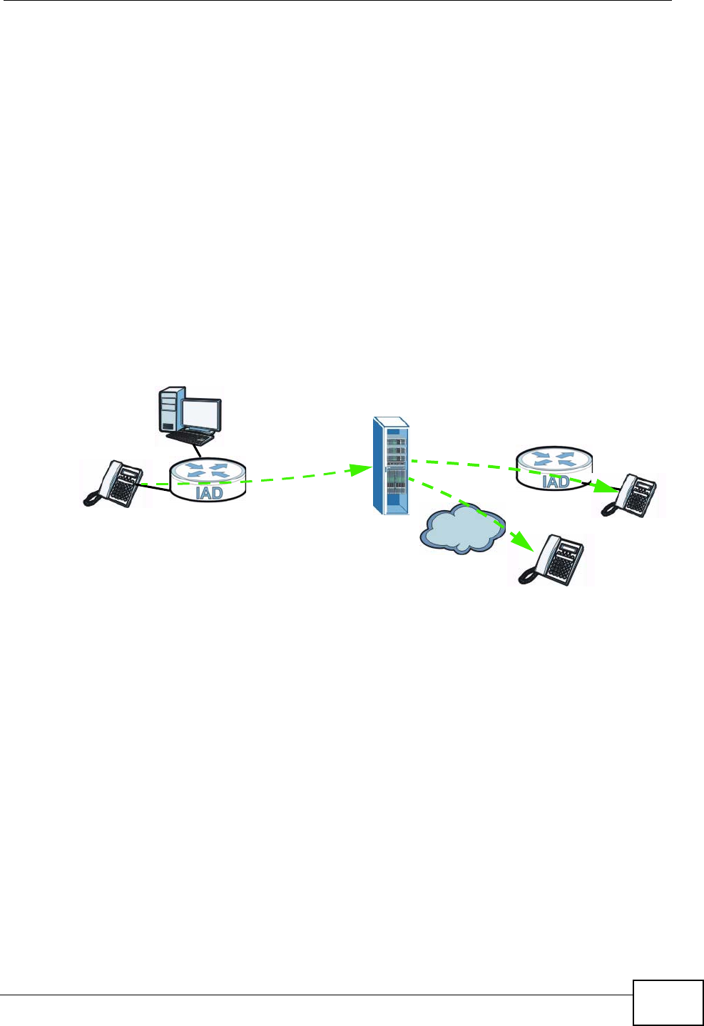
1.2.2 VoIP Features
You can register up to 2 SIP (Session Initiation Protocol) profiles (4 accounts for
each profile) and use the ZyXEL Device to make and receive VoIP telephone calls:
Figure 3 ZyXEL Device’s VoIP Application
The ZyXEL Device sends your call to a VoIP service provider’s SIP server which
forwards your calls to either VoIP or PSTN phones.
PSTN
Chapter 1 Introduction
P-2612HNU(L)-FxF User’s Guide
24
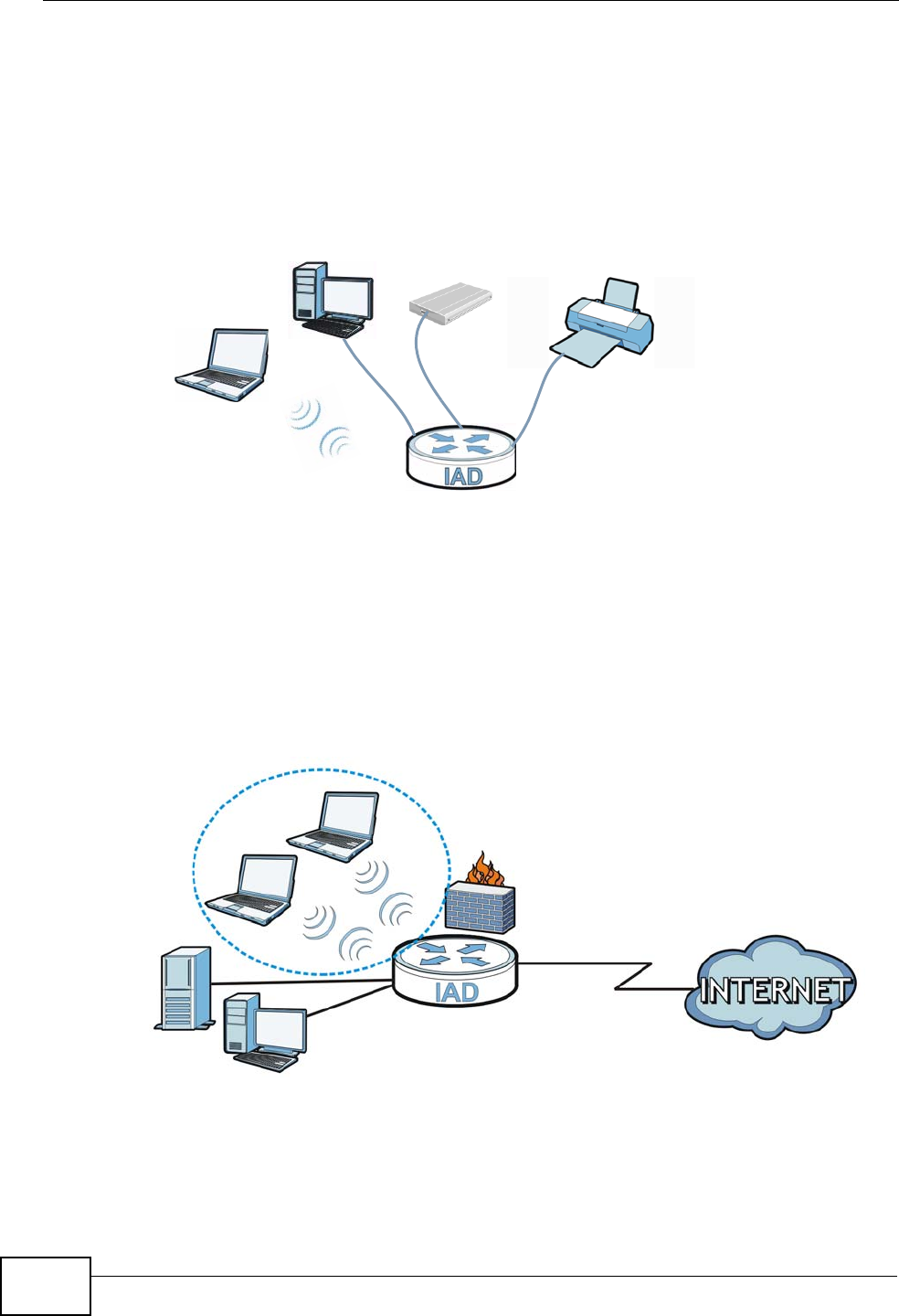
1.2.3 ZyXEL Device’s USB Support
Use the built-in USB 2.0 port to share files via a USB memory stick or a USB hard
drive (A). Alternatively, you can add a USB printer (B) and make it available on
your local area network.
Figure 4 USB File Sharing or Print Server Application
1.2.4 Wireless Connection
By default, the wireless LAN (WLAN) is enabled on the ZyXEL Device. IEEE
802.11b/g/n compliant clients can wirelessly connect to the ZyXEL Device to
access network resources. You can set up a wireless network with WPS (WiFi
Protected Setup) or manually add a client to your wireless network.
Figure 5 Wireless Connection Application
AB
LAN
WLAN
WAN

Chapter 1 Introduction
P-2612HNU(L)-FxF User’s Guide 25
1.3 The WPS/WLAN Button
You can use the WPS button ( ) on the top of the device to turn the wireless
LAN off or on. You can also use it to activate WPS in order to quickly set up a
wireless network with strong security.
Turn the Wireless LAN Off or On
1Make sure the POWER LED is on (not blinking).
2Press the WPS button for one second and release it. The WLAN/WPS LED should
change from on to off or vice versa.
Activate WPS
1Make sure the POWER LED is on (not blinking).
2Press the WPS button for more than five seconds and release it. Press the WPS
button on another WPS -enabled device within range of the ZyXEL Device. The
WLAN/WPS LED should flash while the ZyXEL Device sets up a WPS connection
with the wireless device.
Note: You must activate WPS in the ZyXEL Device and in another wireless device
within two minutes of each other. See Chapter 6 on page 141 for more
information.
1.4 Ways to Manage the ZyXEL Device
Use any of the following methods to manage the ZyXEL Device.
• Web Configurator. This is recommended for everyday management of the ZyXEL
Device using a (supported) web browser.
• Command Line Interface. Line commands are mostly used for troubleshooting
by service engineers.
• FTP for firmware upgrades and configuration backup/restore.
Chapter 1 Introduction
P-2612HNU(L)-FxF User’s Guide
26
1.5 Good Habits for Managing the ZyXEL Device
Do the following things regularly to make the ZyXEL Device more secure and to
manage the ZyXEL Device more effectively.
• Change the password. Use a password that’s not easy to guess and that consists
of different types of characters, such as numbers and letters.
• Write down the password and put it in a safe place.
• Back up the configuration (and make sure you know how to restore it).
Restoring an earlier working configuration may be useful if the device becomes
unstable or even crashes. If you forget your password, you will have to reset the
ZyXEL Device to its factory default settings. If you backed up an earlier
configuration file, you would not have to totally re-configure the ZyXEL Device.
You could simply restore your last configuration.
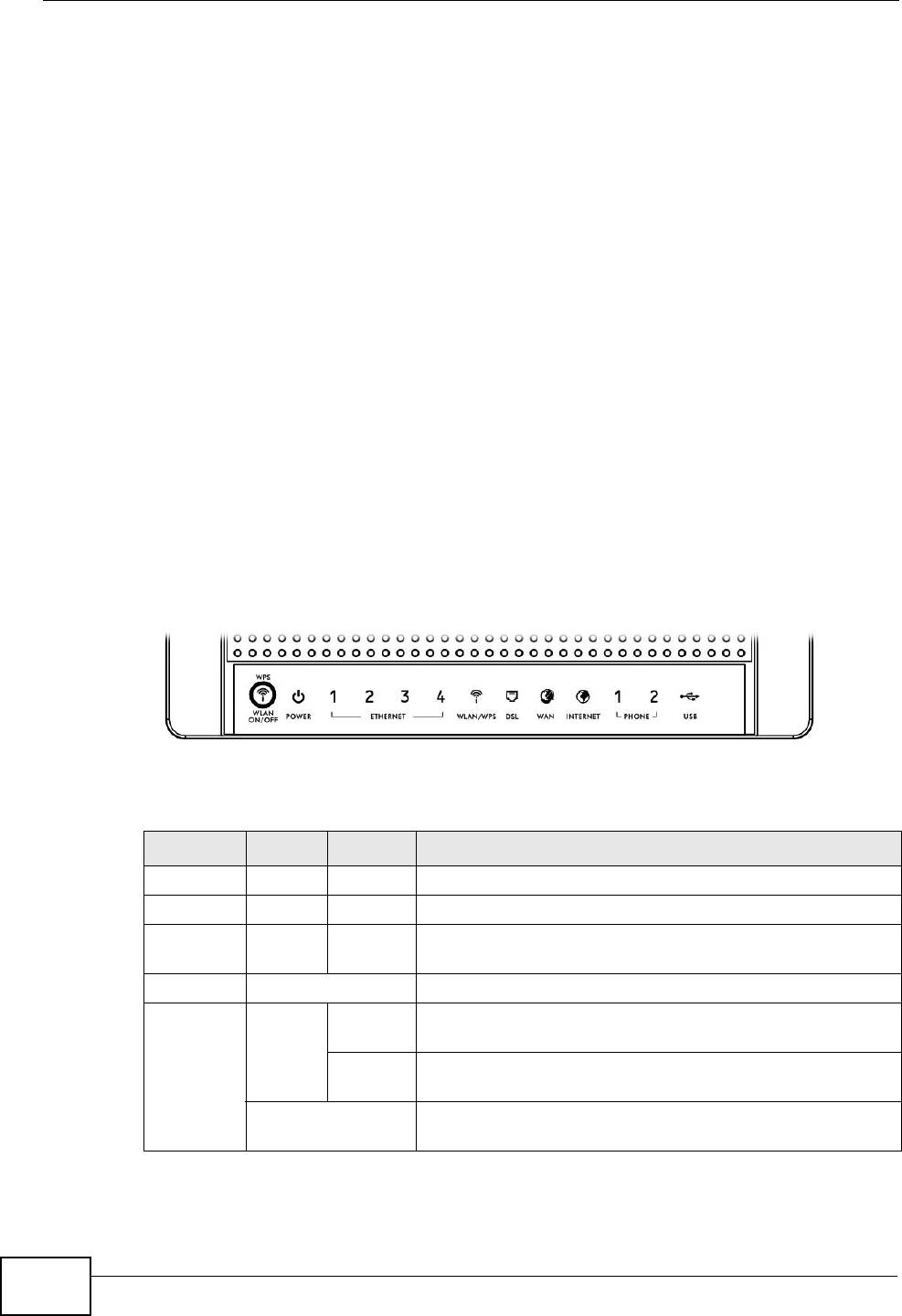
1.6 LEDs (Lights)
The following graphic displays the labels of the LEDs.
Figure 6 LEDs on the Top of the Device
None of the LEDs are on if the ZyXEL Device is not receiving power.
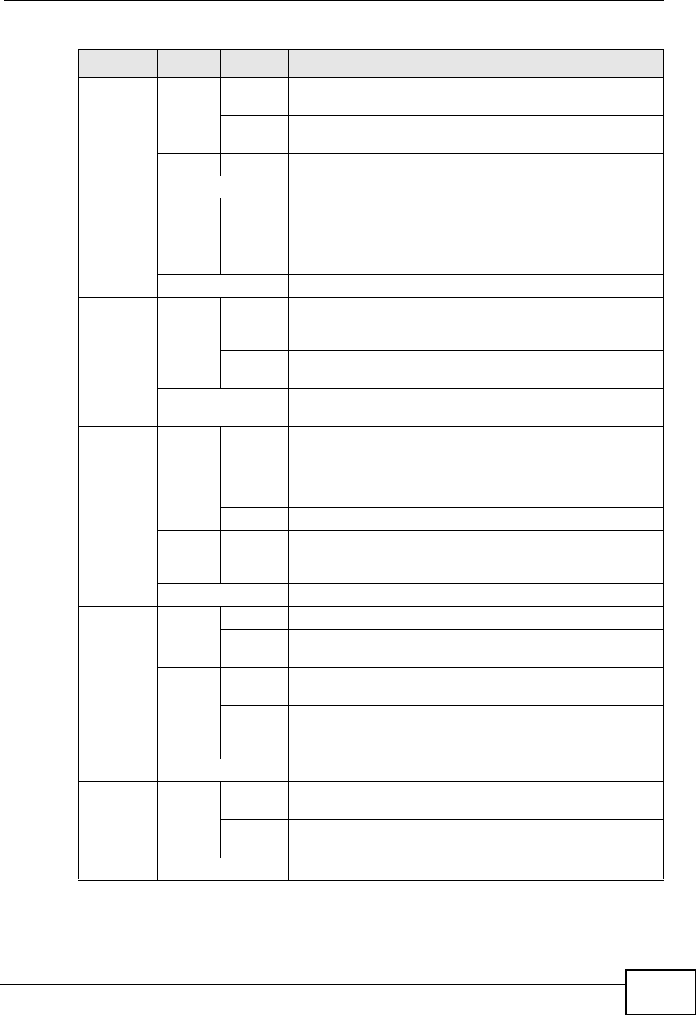
Table 1 LED Descriptions
LED COLOR STATUS DESCRIPTION
POWER Green On The ZyXEL Device is receiving power and ready for use.
Blinking The ZyXEL Device is self-testing.
Red On The ZyXEL Device detected an error while self-testing, or
there is a device malfunction.
Off The ZyXEL Device is not receiving power.
ETHERNET
1-4
Green On The ZyXEL Device has an Ethernet connection with a
device on the Local Area Network (LAN).
Blinking The ZyXEL Device is sending/receiving data to/from the
LAN.
Off The ZyXEL Device does not have an Ethernet connection
with the LAN.
Chapter 1 Introduction
P-2612HNU(L)-FxF User’s Guide 27
Refer to the Quick Start Guide for information on hardware connections.
WLAN/
WPS
Green On The wireless network is activated and is operating in
IEEE 802.11 mode.
Blinking The ZyXEL Device is communicating with other wireless
clients.
Orange Blinking The WPS connection is being configured.
Off The wireless network is not activated.
DSL Green On This light applies when the ZyXEL Device is in DSL WAN
mode. The DSL line is up.
Blinking The ZyXEL Device is attempting to synchronize DSL
signal.
Off The DSL line is down.
WAN Green On This light applies when the ZyXEL Device is in Ethernet
WAN mode. The ZyXEL Device has an Ethernet
connection with a device on the WAN.
Blinking The ZyXEL Device is sending/receiving data to/from the
WAN.
Off The ZyXEL Device does not have an Ethernet connection
with the WAN.
INTERNET Green On The ZyXEL Device has an IP connection but no traffic.
Your device has a WAN IP address (either static or
assigned by a DHCP server), PPP negotiation was
successfully completed (if used).
Blinking The ZyXEL Device is sending or receiving IP traffic.
Red On The ZyXEL Device attempted to make an IP connection
but failed. Possible causes are no response from a DHCP
server, no PPPoE response, PPPoE authentication failed.
Off The ZyXEL Device does not have an IP connection.
PHONE Green On A SIP account is registered for the phone port.
Blinking A telephone connected to the phone port has its receiver
off of the hook or there is an incoming call.
Orange On A SIP account is registered for the phone port and there
is a voice message in the corresponding SIP account.
Blinking A telephone connected to the phone port has its receiver
off of the hook and there is a voice message in the
corresponding SIP account.
Off The phone port does not have a SIP account registered.
USB Green/
Orange
On The ZyXEL Device recognizes a USB connection but there
is no traffic.
Blinking The ZyXEL Device is sending/receiving data to /from the
USB device connected to it.
Off The ZyXEL Device does not detect a USB connection.
Table 1 LED Descriptions
LED COLOR STATUS DESCRIPTION

Chapter 1 Introduction
P-2612HNU(L)-FxF User’s Guide
28
1.7 The RESET Button
If you forget your password or cannot access the web configurator, you will need
to use the RESET button at the back of the device to reload the factory-default
configuration file. This means that you will lose all configurations that you had
previously and the passwords will be reset to the defaults.
1Make sure the POWER LED is on (not blinking).
2To set the device back to the factory default settings, press the RESET button for
5 seconds or until the POWER LED begins to blink and then release it. When the
POWER LED begins to blink, the defaults have been restored and the device
restarts.

P-2612HNU(L)-FxF User’s Guide 29
CHAPTER 2
Introducing the Web
Configurator
2.1 Overview
The web configurator is an HTML-based management interface that allows easy
device setup and management via Internet browser. Use Internet Explorer 6.0 and
later versions, Mozilla Firefox 3 and later versions, or Safari 2.0 and later versions.
The recommended screen resolution is 1024 by 768 pixels.
In order to use the web configurator you need to allow:
• Web browser pop-up windows from your device. Web pop-up blocking is enabled
by default in Windows XP SP (Service Pack) 2.
• JavaScript (enabled by default).
• Java permissions (enabled by default).
See Appendix C on page 347 if you need to make sure these functions are allowed
in Internet Explorer.
2.1.1 Accessing the Web Configurator
1Make sure your ZyXEL Device hardware is properly connected (refer to the Quick
Start Guide).
2Launch your web browser.
3Type "192.168.1.1" as the URL.
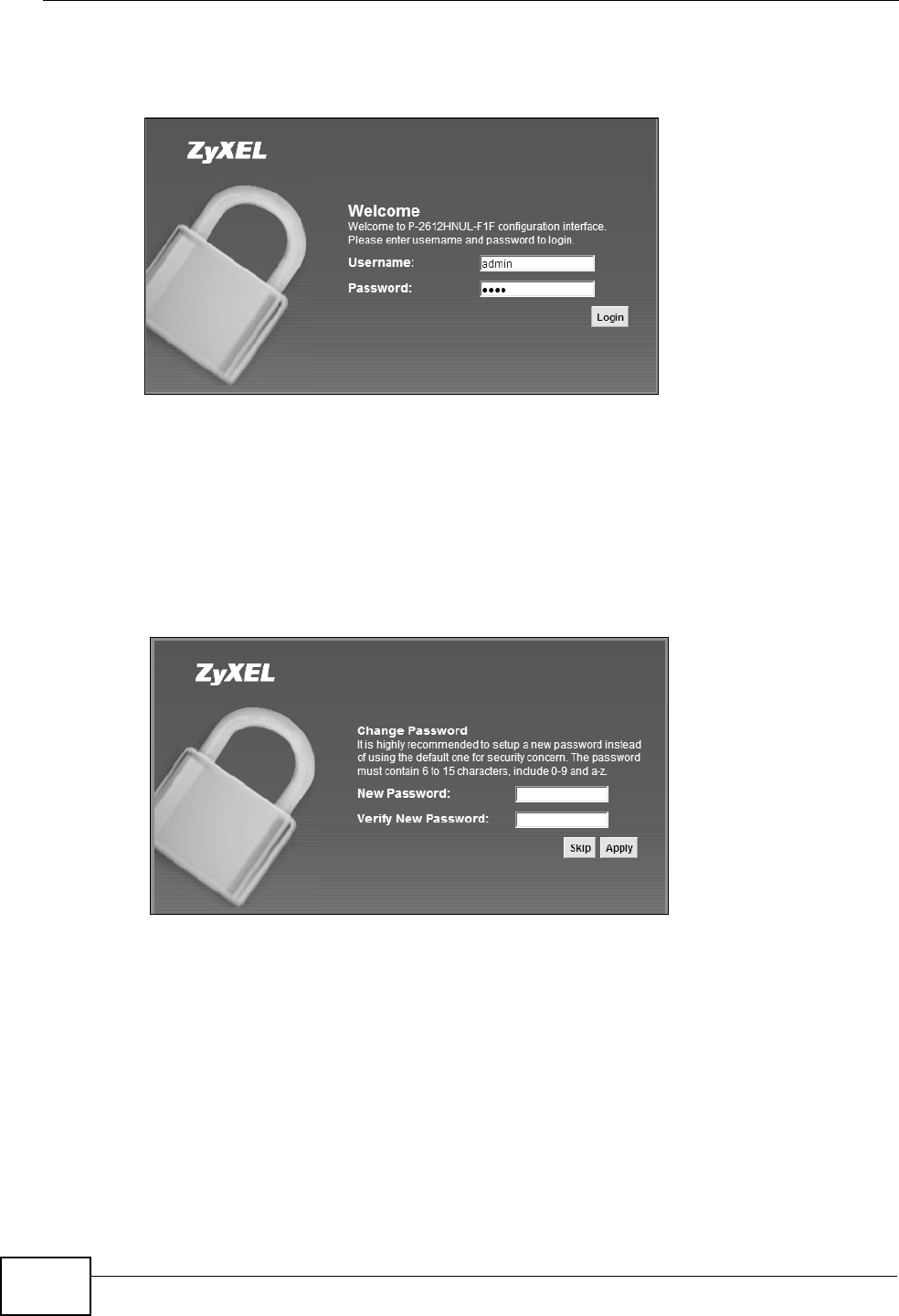
4A password screen displays. Type “admin” or “user” (default) as the account
username and “1234” as the password, and click Login. Some features are not
configurable with the user account.
Chapter 2 Introducing the Web Configurator
P-2612HNU(L)-FxF User’s Guide
30
If you have changed the password, enter your password and click Login.
Figure 7 Password Screen
Note: For security reasons, the ZyXEL Device automatically logs you out if you do not
use the web configurator for five minutes (default). If this happens, log in again.
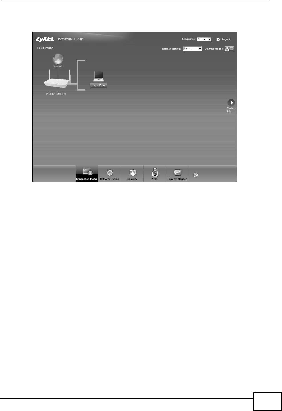
5The following screen displays if you have not yet changed your password. It is
strongly recommended you change the default password. Enter a new password,
retype it to confirm and click Apply; alternatively click Skip to proceed to the
main menu if you do not want to change the password now.
Figure 8 Change Password Screen
Chapter 2 Introducing the Web Configurator
P-2612HNU(L)-FxF User’s Guide 31
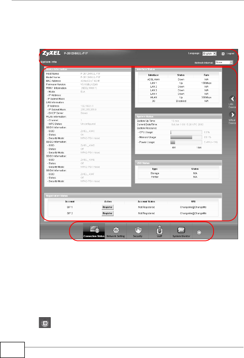
6The Connection Status screen appears.
Figure 9 Connection Status
7Click System Info to display the System Info screen, where you can view the
ZyXEL Device’s interface and system information.
Chapter 2 Introducing the Web Configurator
P-2612HNU(L)-FxF User’s Guide
32
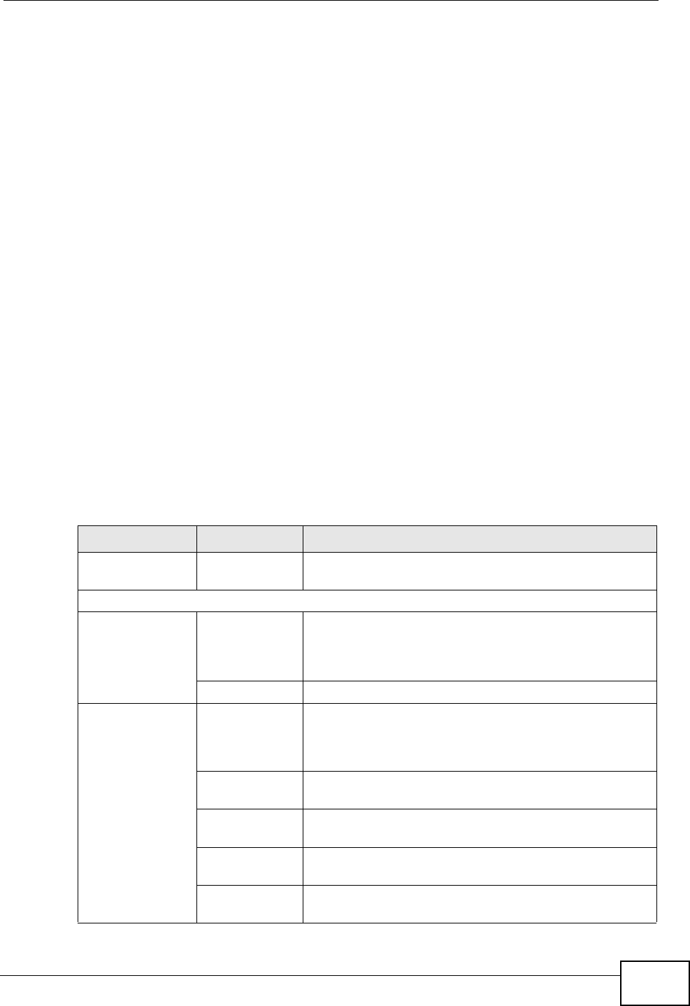
2.2 The Web Configurator Layout
Click Connection Status > System Info to show the following screen.
Figure 10 Web Configurator Layout
As illustrated above, the main screen is divided into these parts:
•A - title bar
•B- main window
•C- navigation panel
2.2.1 Title Bar
The title bar shows the following icon in the upper right corner.
B
C
A
Chapter 2 Introducing the Web Configurator
P-2612HNU(L)-FxF User’s Guide 33
Click this icon to log out of the web configurator.
2.2.2 Main Window
The main window displays information and configuration fields. It is discussed in
the rest of this document.
After you click System Info on the Connection Status screen, the System Info
screen is displayed. See Chapter 4 on page 87 for more information about the
System Info screen.
If you click LAN Device on the System Info screen, the Connection Status
screen appears. See Chapter 4 on page 85 for more information about the
Connection Status screen.
If you click Virtual Device on the System Info screen, a visual graphic appears,
showing the connection status of the ZyXEL Device’s ports. The connected ports
are in color and disconnected ports are gray.
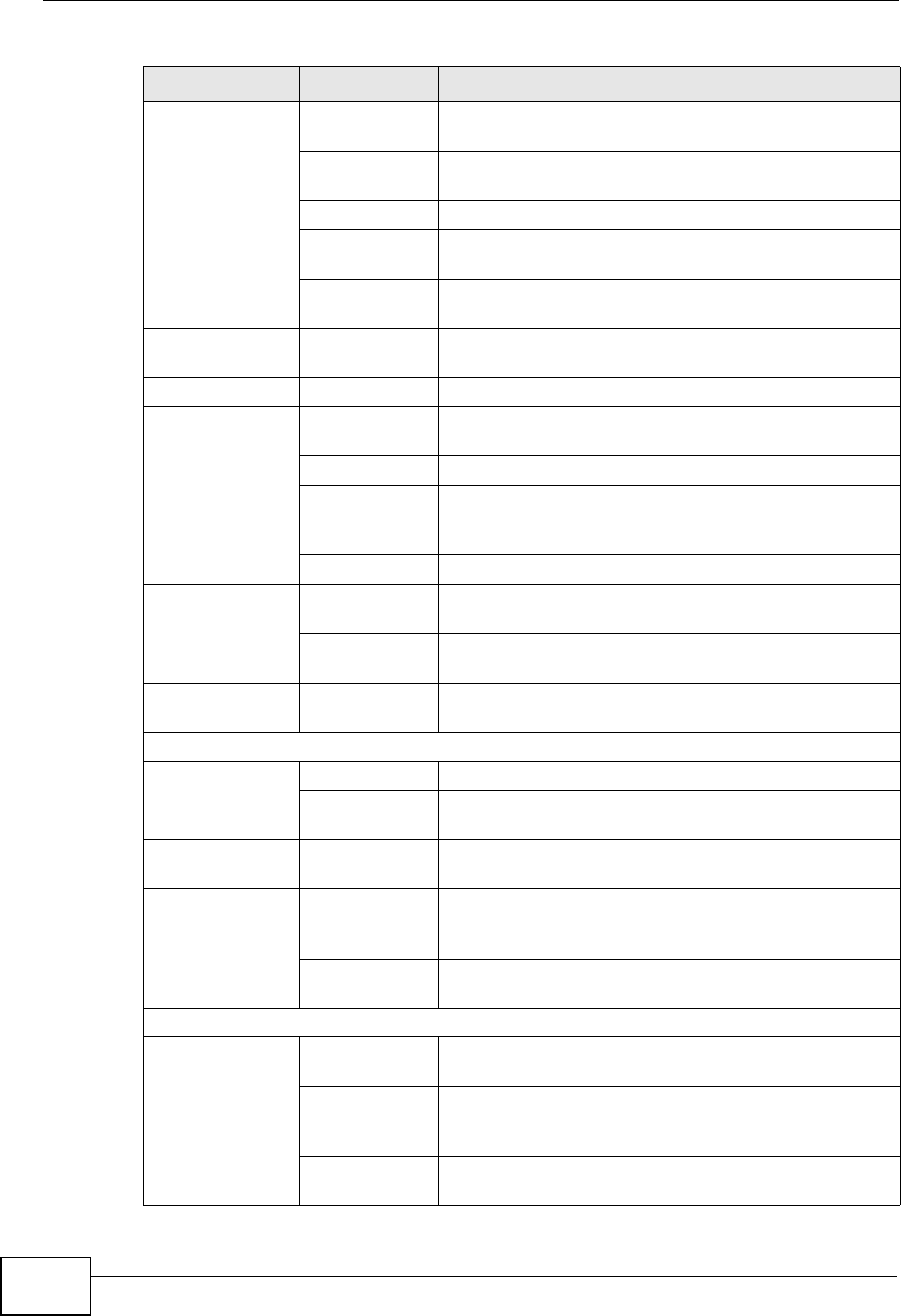
2.2.3 Navigation Panel
Use the menu items on the navigation panel to open screens to configure ZyXEL
Device features. The following table describes each menu item.
Table 2 Navigation Panel Summary
LINK TAB FUNCTION
Connection
Status
This screen shows the network status of the ZyXEL
Device and computers/devices connected to it.
Network Setting
Broadband Broadband Use this screen to view, remove or add a WAN
interface. You can also configure ISP parameters,
WAN IP address assignment, DNS servers and other
advanced properties.
3G Backup Use this screen to configure the 3G WAN connection.
Wireless General Use this screen to turn the wireless connection on or
off, specify the SSID(s) and configure the wireless
LAN settings and WLAN authentication/security
settings.
More AP Use this screen to configure multiple BSSs on the
ZyXEL Device.
WPS Use this screen to use WPS (Wi-Fi Protected Setup) to
establish a wireless connection.
WMM Use this screen to enable or disable Wi-Fi MultiMedia
(WMM).
Scheduling Use this screen to configure when the ZyXEL Device
enables or disables the wireless LAN.
Chapter 2 Introducing the Web Configurator
P-2612HNU(L)-FxF User’s Guide
34
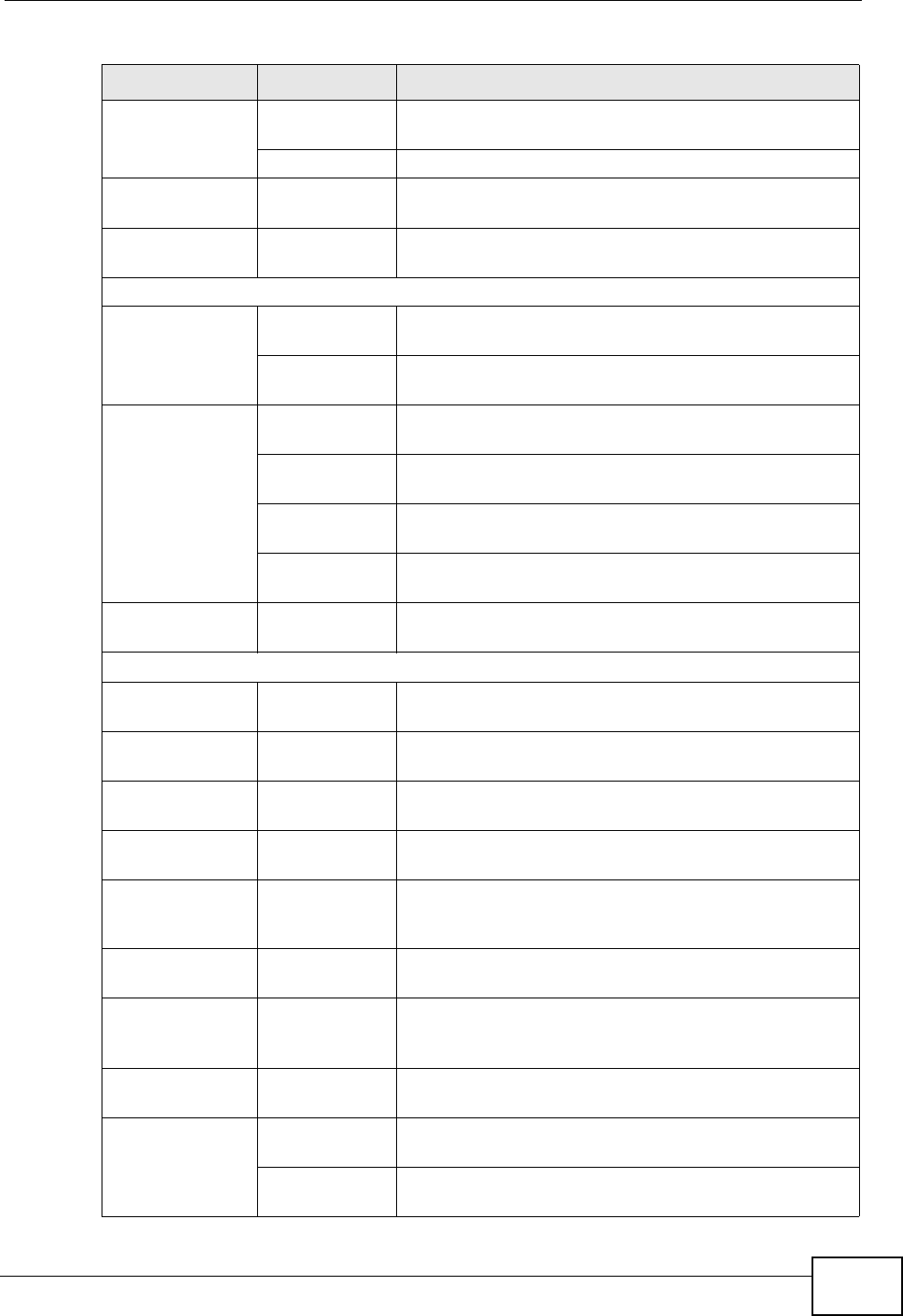
Home
Networking LAN Setup Use this screen to configure LAN TCP/IP settings, and
other advanced properties.
Static DHCP Use this screen to assign specific IP addresses to
individual MAC addresses.
UPnP Use this screen to enable the UPnP function.
File Sharing Use this screen to enable file sharing via the ZyXEL
Device.
Printer Server Use this screen to enable or disable sharing of a USB
printer via your ZyXEL Device.
Routing Static Route Use this screen to view and set up static routes on the
ZyXEL Device.
DNS Route DNS Route Use this screen to view and configure DNS routes.
QoS General Use this screen to enable QoS and decide allowable
bandwidth using QoS.
Queue Setup Use this screen to configure QoS queue assignment.
Class Setup Use this screen to set up classifiers to sort traffic into
different flows and assign priority and define actions
to be performed for a classified traffic flow.
Monitor Use this screen to view each queue’s statistics.
NAT Port
Forwarding
Use this screen to make your local servers visible to
the outside world.
Sessions Use this screen to limit the number of NAT sessions a
single client can establish.
DNS Dynamic DNS Use this screen to allow a static hostname alias for a
dynamic IP address.
Security
Firewall General Use this screen to activate/deactivate the firewall.
Services Use this screen to set the default action to take on
network traffic going in specific directions.
MAC Filter MAC Filter Use this screen to allow specific devices to access the
ZyXEL Device.
Certificates Local
Certificates
Use this screen to generate and export self-signed
certificates or certification requests and import the
ZyXEL Device’s CA-signed certificates.
Trusted CAs Use this screen to save CA certificates to the ZyXEL
Device.
VoIP
SIP SIP Service
Provider
Use this screen to configure your ZyXEL Device’s
Voice over IP settings.
SIP Account Use this screen to set up information about your SIP
account and configure audio settings such as volume
levels for the phones connected to the ZyXEL Device.
Common Use this screen to configure RFC3262 support on the
ZyXEL Device.
Table 2 Navigation Panel Summary (continued)
LINK TAB FUNCTION
Chapter 2 Introducing the Web Configurator
P-2612HNU(L)-FxF User’s Guide 35
Phone Phone Device Use this screen to set which phone ports use which
SIP accounts.
Region Use this screen to select your location.
Call Rule Speed Dial Use this screen to configure speed dial for SIP phone
numbers that you call often.
FXO FXO Use this screen to set up the PSTN line you use to
make regular phone calls.
System Monitor
Log Phone Log Use this screen to view the ZyXEL Device’s phone
logs.
VoIP Call
History
Use this screen to view the ZyXEL Device’s VoIP call
history.
Traffic Status WAN Use this screen to view the status of all network traffic
going through the WAN port of the ZyXEL Device.
LAN Use this screen to view the status of all network traffic
going through the LAN ports of the ZyXEL Device.
NAT Use this screen to view the status of NAT sessions on
the ZyXEL Device.
3G Backup Use this screen to view the status of 3G Backup on
the ZyXEL Device.
VoIP Status VoIP Status Use this screen to view the SIP, phone, and call status
of the ZyXEL Device.
Maintenance
Users
Account Users Account Use this screen to configure the passwords your user
accounts.
Remote
MGMT Remote MGMT Use this screen to enable specific traffic directions for
network services.
System System Use this screen to configure the ZyXEL Device’s name,
domain name, management inactivity time-out.
Time Setting Time Setting Use this screen to change your ZyXEL Device’s time
and date.
Log Setting Log Setting Use this screen to select which logs and/or immediate
alerts your device is to record. You can also set it to e-
mail the logs to you.
Firmware
Upgrade Firmware
Upgrade
Use this screen to upload firmware to your device.
Backup/
Restore Backup/
Restore
Use this screen to backup and restore your device’s
configuration (settings) or reset the factory default
settings.
Reboot Reboot Use this screen to reboot the ZyXEL Device without
turning the power off.
Diagnostic Ping Use this screen to test the connections to other
devices.
DSL Line Use this screen to identify problems with the DSL
connection.
Table 2 Navigation Panel Summary (continued)
LINK TAB FUNCTION

Chapter 2 Introducing the Web Configurator
P-2612HNU(L)-FxF User’s Guide
36

P-2612HNU-Fx User’s Guide 37
CHAPTER 3
Tutorials
3.1 Overview
This chapter contains the following tutorials:
•Setting Up Your DSL Connection
•How to Set up a Wireless Network
•Setting Up NAT Port Forwarding
•How to Make a VoIP Call
•Using the File Sharing Feature
•Using the Print Server Feature
•Configuring the MAC Address Filter
•Configuring Static Route for Routing to Another Network
•Configuring QoS Queue and Class Setup
•Access the ZyXEL Device Using DDNS
3.2 Setting Up Your DSL Connection
This tutorial shows you how to set up your Internet connection using the web
configurator.
If you connect to the Internet through a DSL connection, use the information from
your Internet Service Provider (ISP) to configure the ZyXEL Device. Do the
following steps:
1Connect the ZyXEL Device properly. Refer to the Quick Start Guide for details on
the ZyXEL Device’s hardware connection.
2Check the back panel of your device where the Ethernet ports are located and
make sure the DSL/WAN switch is pointing up to DSL.
Chapter 3 Tutorials
P-2612HNU-Fx User’s Guide
38
3Connect one end of a DSL cable to the DSL port of your ZyXEL Device. The other
end should be connected to the DSL port in your house or a DSL router/modem
provided by your ISP.
4Connect one end of Ethernet cable to an Ethernet port on the ZyXEL Device and
the other end to a computer that you will use to access the web configurator.
5Connect the ZyXEL Device to a power source, turn it on and wait for the POWER
LED to become a steady green. Turn on the modem provided by your ISP as well
as the computer.
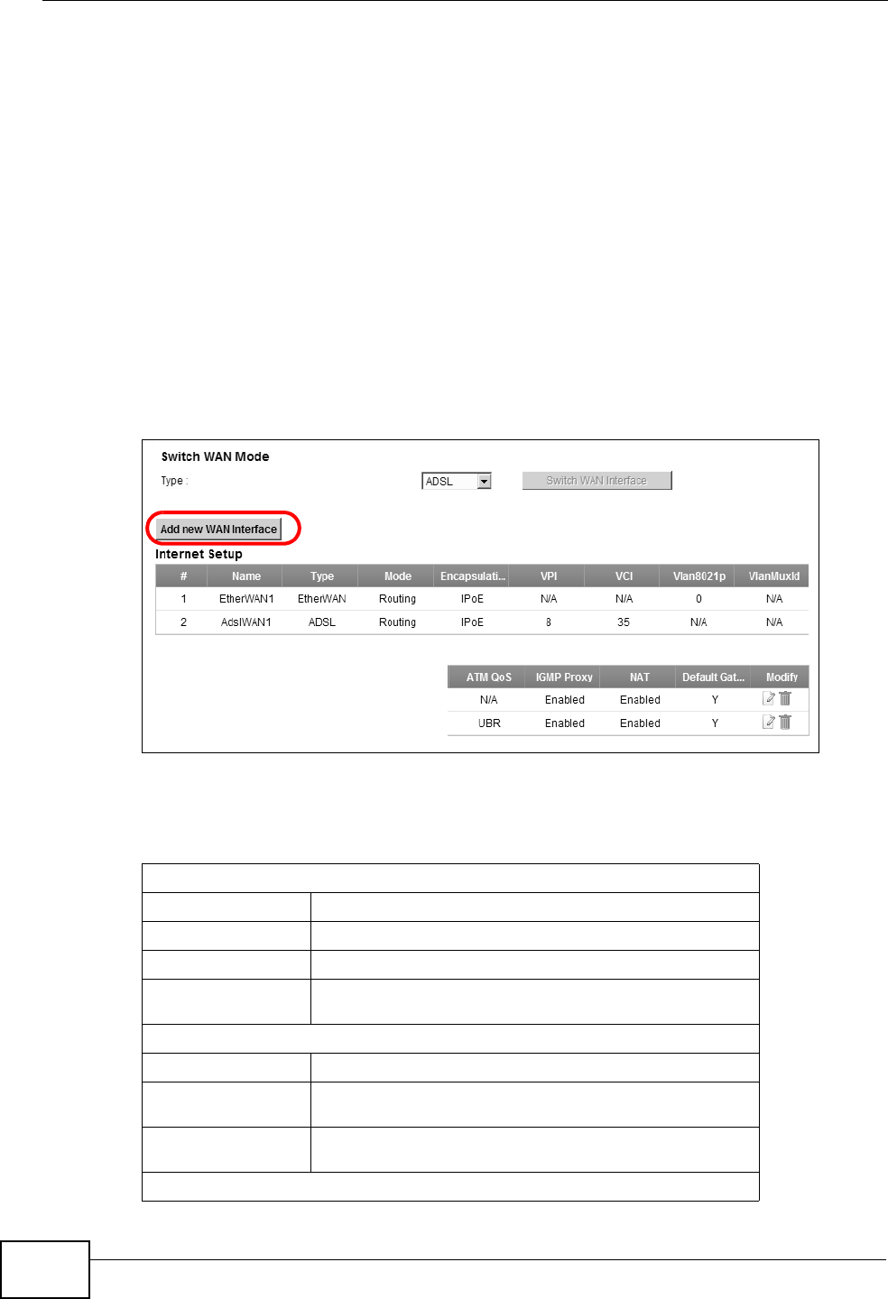
Account Configuration
1Click Network Setting > Broadband to open the following screen. Click Add
new WAN Interface.
2For this example, the interface type is ADSL and the connection has the following
information.
General
Name MyDSLConnection
Type ADSL
Mode Routing
WAN Service
Type PPPoE
ATM PVC Configuration
VPI/VCI 36/48
Encapsulation
Mode LLC/SNAP-Bridging
Service
Category UBR without PCR
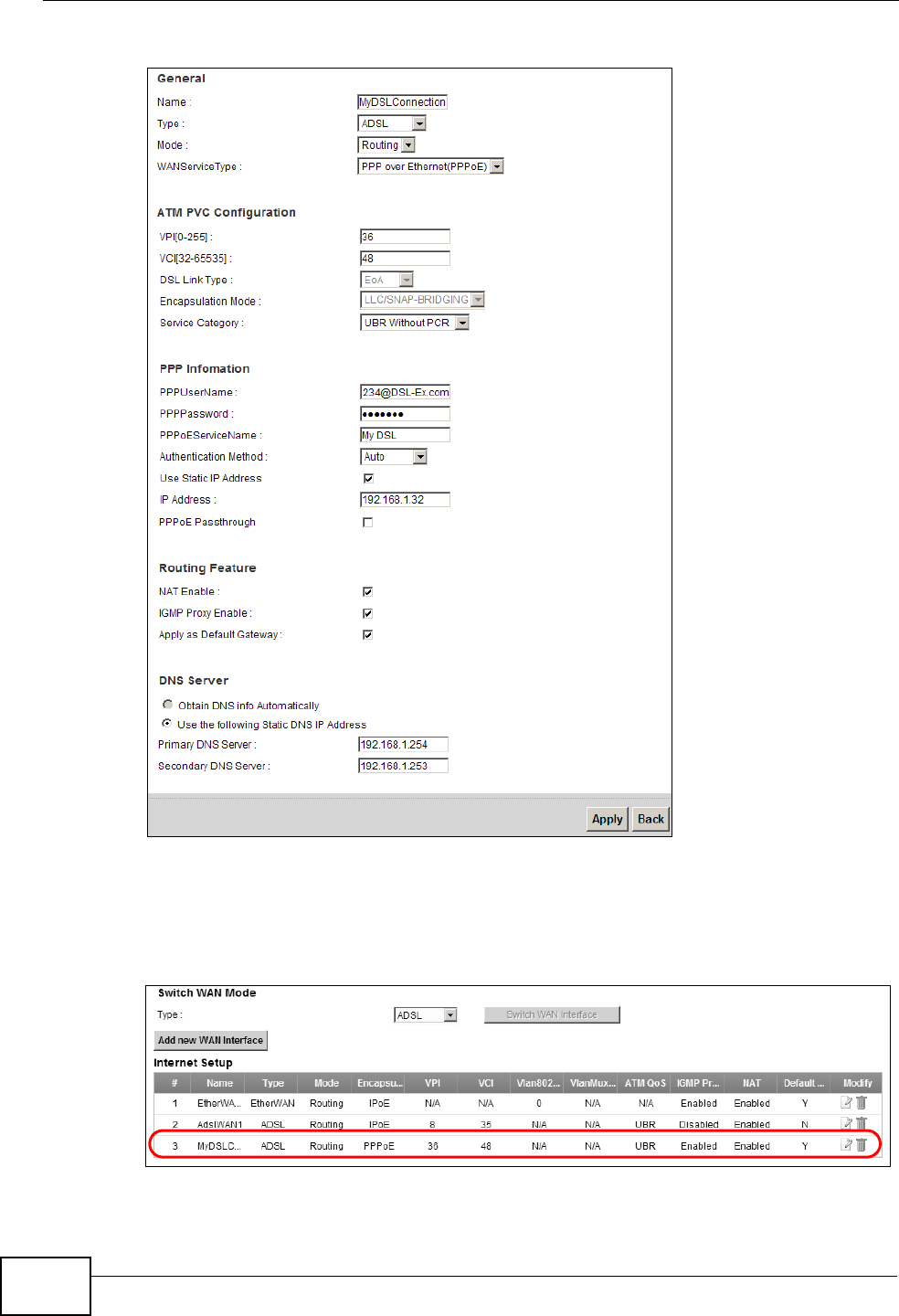
PPP Information

Chapter 3 Tutorials
P-2612HNU-Fx User’s Guide 39
PPP User Name 1234@DSL-Ex.com
PPP Password ABCDEF!
PPPoE Service
Name My DSL
Authentication
Method Auto
Static IP
Address 192.168.1.32
Others PPPoE Passthrough: Disabled
NAT: Enabled
IGMP Multicast Proxy: Enabled
Apply as Default Gateway: Enable
DNS Server: Static DNS IP Address (Primary:
192.168.1.254 Secondary: 192.168.1.253)
Chapter 3 Tutorials
P-2612HNU-Fx User’s Guide
40
Enter or select these values and click Apply.
This completes your DSL WAN connection setting.
3You should see a summary of your new DSL connection setup in the Broadband
screen as follows.

Chapter 3 Tutorials
P-2612HNU-Fx User’s Guide 41
Try to connect to a website, such as “www. zyxel.com” to see if you have correctly
set up your Internet connection. Be sure to contact your service provider for any
information you need to configure the WAN screens.
3.3 How to Set up a Wireless Network
This section gives you examples of how to set up an access point and wireless
client for wireless communication using the following parameters. The wireless
clients can access the Internet through the ZyXEL Device wirelessly.
3.3.1 Example Parameters
An access point (AP) or wireless router is referred to as the “AP” and a computer
with a wireless network card or USB adapter is referred to as the “wireless client”
here.
We use the P-2612HNU-Fx web screens and M-302 utility screens as an example.
The screens may vary slightly for different models.
3.3.2 Configuring the AP
Follow the steps below to configure the wireless settings on your AP.
SSID SSID_Example3
802.11 mode 802.11b/g
Channel auto
Security WPA-PSK
(Pre-Shared Key: ThisismyWPA-PSKpre-sharedkey)
Chapter 3 Tutorials
P-2612HNU-Fx User’s Guide
42
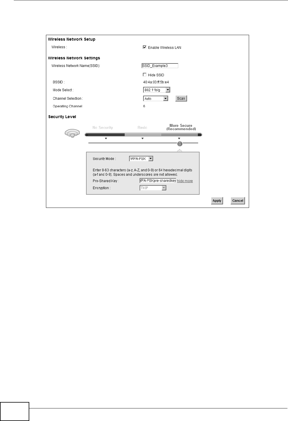
1Open the Network Setting > Wireless > General screen in the AP’s web
configurator.
Tutorial: Network > Wireless LAN > Ge neral
2Make sure Enable Wireless LAN is selected.
3Enter “SSID_Example3” as the SSID and select Auto in the Channel Selection
field to have the device search for an available channel.
4Select 802.11b/g in the Mode Select field.
5Select More Secure as your security level and set security mode to WPA-PSK
and enter “ThisismyWPA-PSKpre-sharedkey” in the Pre-Shared Key field. Click
Apply.
Chapter 3 Tutorials
P-2612HNU-Fx User’s Guide 43
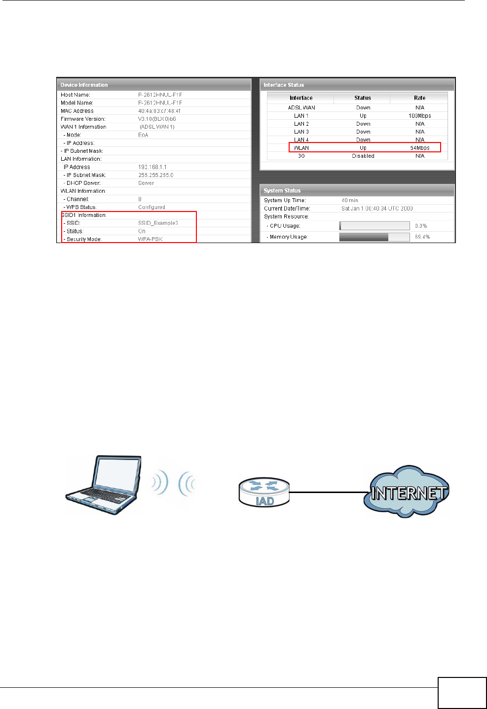
6Click Connection Status > System Info.Verify your wireless and wireless
security settings under Device Information and check if the WLAN connection is
up under Interface Status.
Tutorial: Network > Wireless LAN > Se curitOpen the Status screen. Verify your wireless and wirel ess security settings under Devi ce Information and check if the WLAN connection is up un der Interface Status
Tutorial: Status
This finishes the configuration of the AP.
3.3.3 Configuring the Wireless Client
This section describes how to connect the wireless client to a network.
3.3.3.1 Connecting to a Wireless LAN
The following sections show you how to join a wireless network using the ZyXEL
utility, as in the following diagram. The wireless client is labeled Cand the access
point is labeled AP.
Wireless LAN Setup
There are three ways to connect the client to an access point.
• Configure nothing and leave the wireless client to automatically scan for and
connect to any available network that has no wireless security configured.
• Manually connect to a network.
• Configure a profile to have the wireless client automatically connect to a specific
network or peer computer.
CAP
Chapter 3 Tutorials
P-2612HNU-Fx User’s Guide
44
This example illustrates how to manually connect your wireless client to an access
point (AP) which is configured for WPA-PSK security and connected to the
Internet. Before you connect to the access point, you must know its Service Set
IDentity (SSID) and WPA-PSK pre-shared key. In this example, the SSID is
“SSID_Example3” and the pre-shared key is “ThisismyWPA-PSKpre-sharedkey”.
After you install the ZyXEL utility and then insert the wireless client, follow the
steps below to connect to a network using the Site Survey screen.
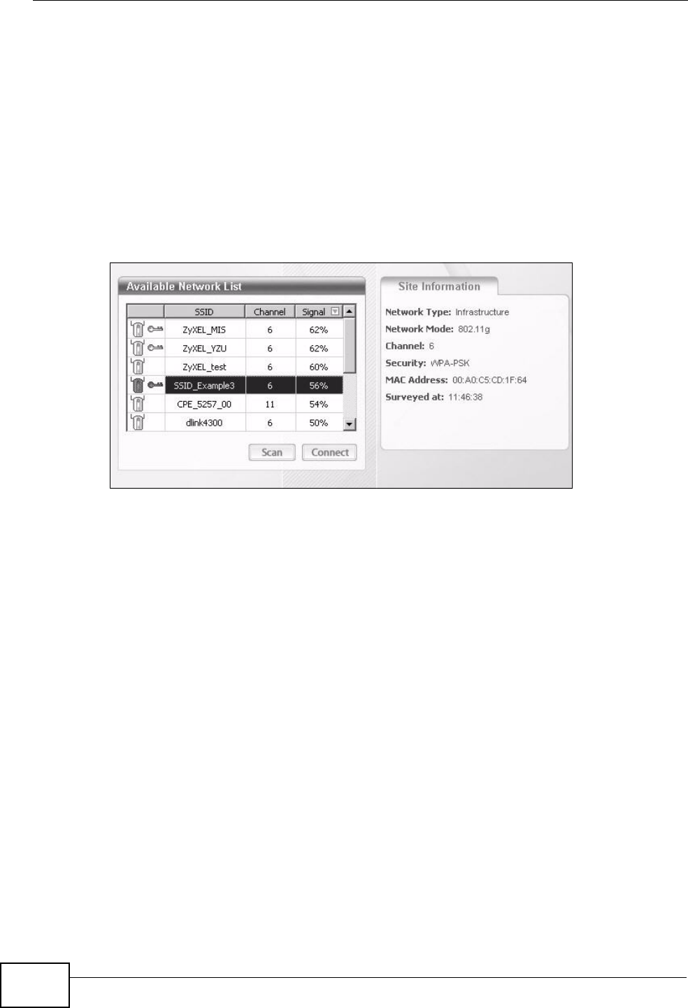
1Open the ZyXEL utility and click the Site Survey tab to open the screen shown
next.
Tutorial: Site Survey
2The wireless client automatically searches for available wireless networks. Click
Scan if you want to search again. If no entry displays in the Available Network
List, that means there is no wireless network available within range. Make sure
the AP or peer computer is turned on or move the wireless client closer to the AP
or peer computer.
Chapter 3 Tutorials
P-2612HNU-Fx User’s Guide 45
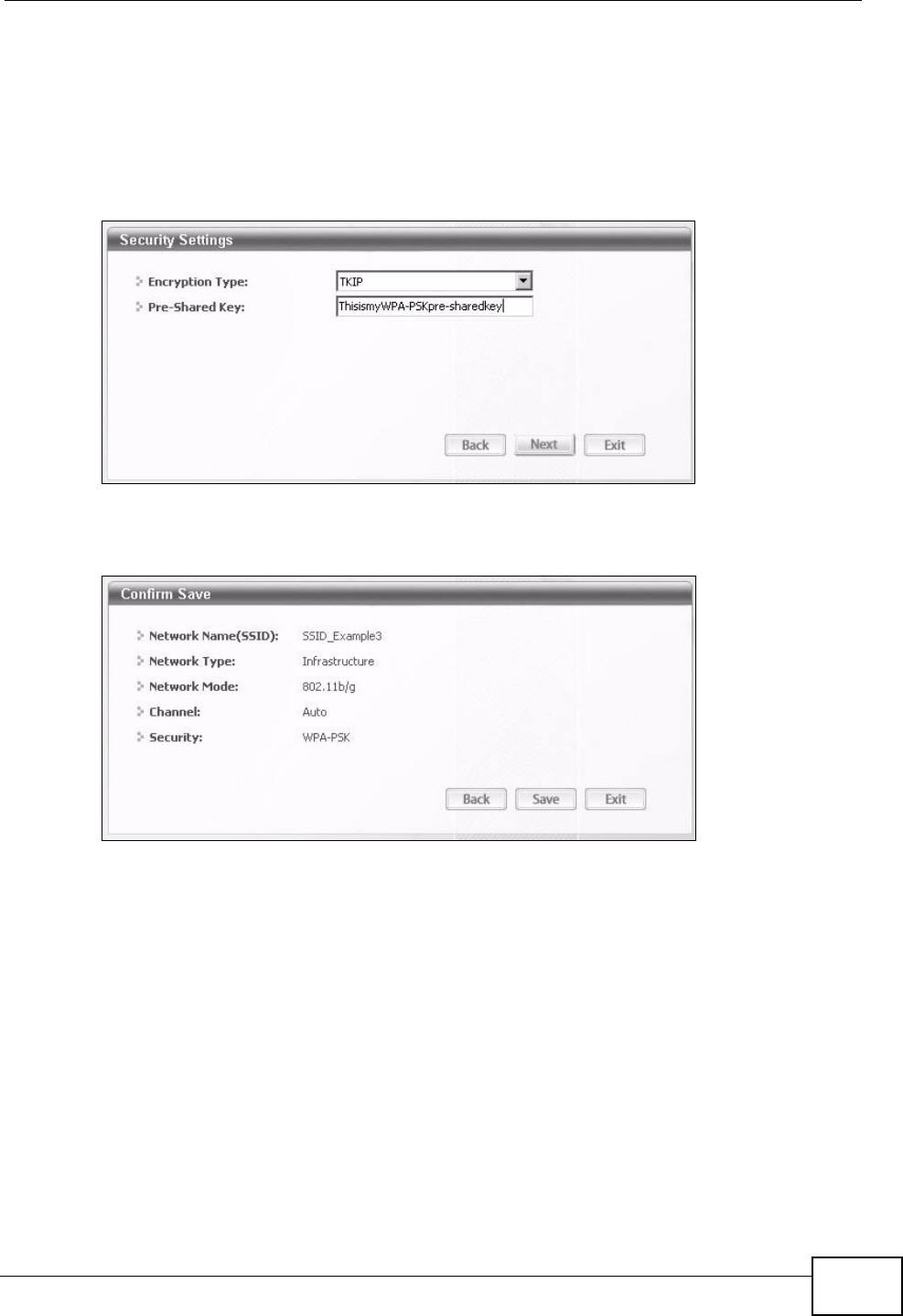
3When you try to connect to an AP with security configured, a window will pop up
prompting you to specify the security settings. Enter the pre-shared key and leave
the encryption type at the default setting.
Use the Next button to move on to the next screen. You can use the Back button
at any time to return to the previous screen, or the Exit button to return to the
Site Survey screen.
Tutorial: Security Settings
4The Confirm Save window appears. Check your settings and click Save to
continue.
Tutorial: Confirm Save
Chapter 3 Tutorials
P-2612HNU-Fx User’s Guide
46
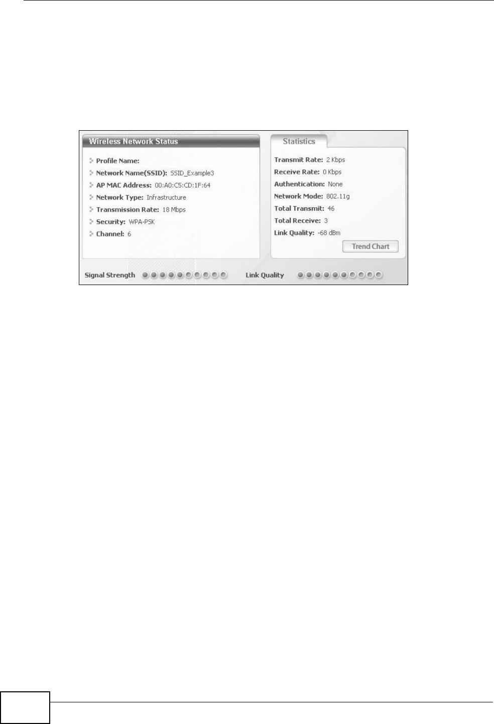
5The ZyXEL utility returns to the Link Info screen while it connects to the wireless
network using your settings. When the wireless link is established, the ZyXEL
utility icon in the system tray turns green and the Link Info screen displays
details of the active connection. Check the network information in the Link Info
screen to verify that you have successfully connected to the selected network. If
the wireless client is not connected to a network, the fields in this screen remain
blank.
Tutorial: Link Info
6Open your Internet browser and enter http://www.zyxel.com or the URL of any
other web site in the address bar. If you are able to access the web site, your
wireless connection is successfully configured.
If you cannot access the web site, try changing the encryption type in the
Security Settings screen, check the Troubleshooting section of this User's Guide
or contact your network administrator.
3.3.3.2 Creating and Using a Profile
A profile lets you easily connect to the same wireless network again later. You can
also configure different profiles for different networks, for example if you connect
a notebook computer to wireless networks at home and at work.
This example illustrates how to set up a profile and connect the wireless client to
an AP configured for WPA-PSK security. In this example, the SSID is
“SSID_Example3”, the profile name is “PN_Example3” and the pre-shared key is
“ThisismyWPA-PSKpre-sharedkey”. You have chosen the profile name
“PN_Example3”.
Chapter 3 Tutorials
P-2612HNU-Fx User’s Guide 47
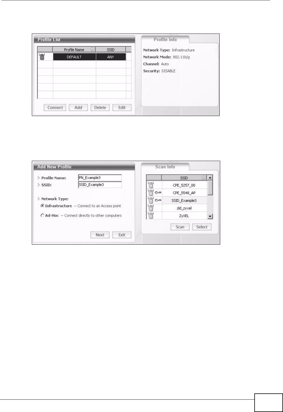
1Open the ZyXEL utility and click the Profile tab to open the screen shown next.
Click Add to configure a new profile.
Tutorial: Profile
2The Add New Profile screen appears. The wireless client automatically searches
for available wireless networks, and displays them in the Scan Info box. Click
Scan if you want to search again. You can also configure your profile for a wireless
network that is not in the list.
Tutorial: Add New Profile
3Give the profile a descriptive name (of up to 32 printable ASCII characters). Select
Infrastructure and either manually enter or select the AP's SSID in the Scan
Info table and click Select.
Chapter 3 Tutorials
P-2612HNU-Fx User’s Guide
48
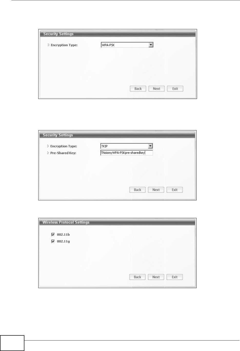
4Choose the same encryption method as the AP to which you want to connect (In
this example, WPA-PSK).
Tutorial: Profile Security
5This screen varies depending on the encryption method you selected in the
previous screen. Enter the pre-shared key and leave the encryption type at the
default setting.
Tutorial: Profile Encryption
6In the next screen, leave both boxes selected.
Tutorial: Wireless Protocol Settings.
Chapter 3 Tutorials
P-2612HNU-Fx User’s Guide 49
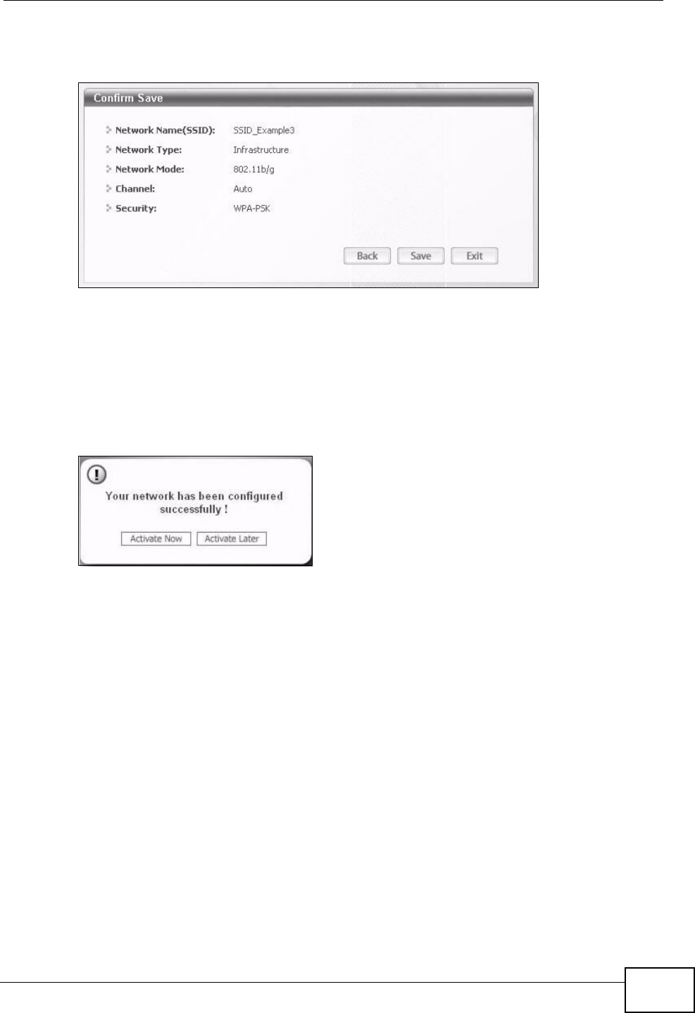
7Verify the profile settings in the read-only screen. Click Save to save and go to the
next screen.
Tutorial: Confirm Save
8Click Activate Now to use the new profile immediately. Otherwise, click the
Activate Later button.
If you clicked Activate Later, you can select the profile from the list in the Profile
screen and click Connect to activate it.
Note: Only one profile can be activated and used at any given time.
Tutorial: Activate
9When you activate the new profile, the ZyXEL utility returns to the Link Info
screen while it connects to the AP using your settings. When the wireless link is
established, the ZyXEL utility icon in the system tray turns green and the Link
Info screen displays details of the active connection.
10 Open your Internet browser, enter http://www.zyxel.com or the URL of any other
web site in the address bar and press ENTER. If you are able to access the web
site, your new profile is successfully configured.
11 If you cannot access the Internet go back to the Profile screen, select the profile
you are using and click Edit. Check the details you entered previously. Also, refer
to the Troubleshooting section of this User's Guide or contact your network
administrator if necessary.
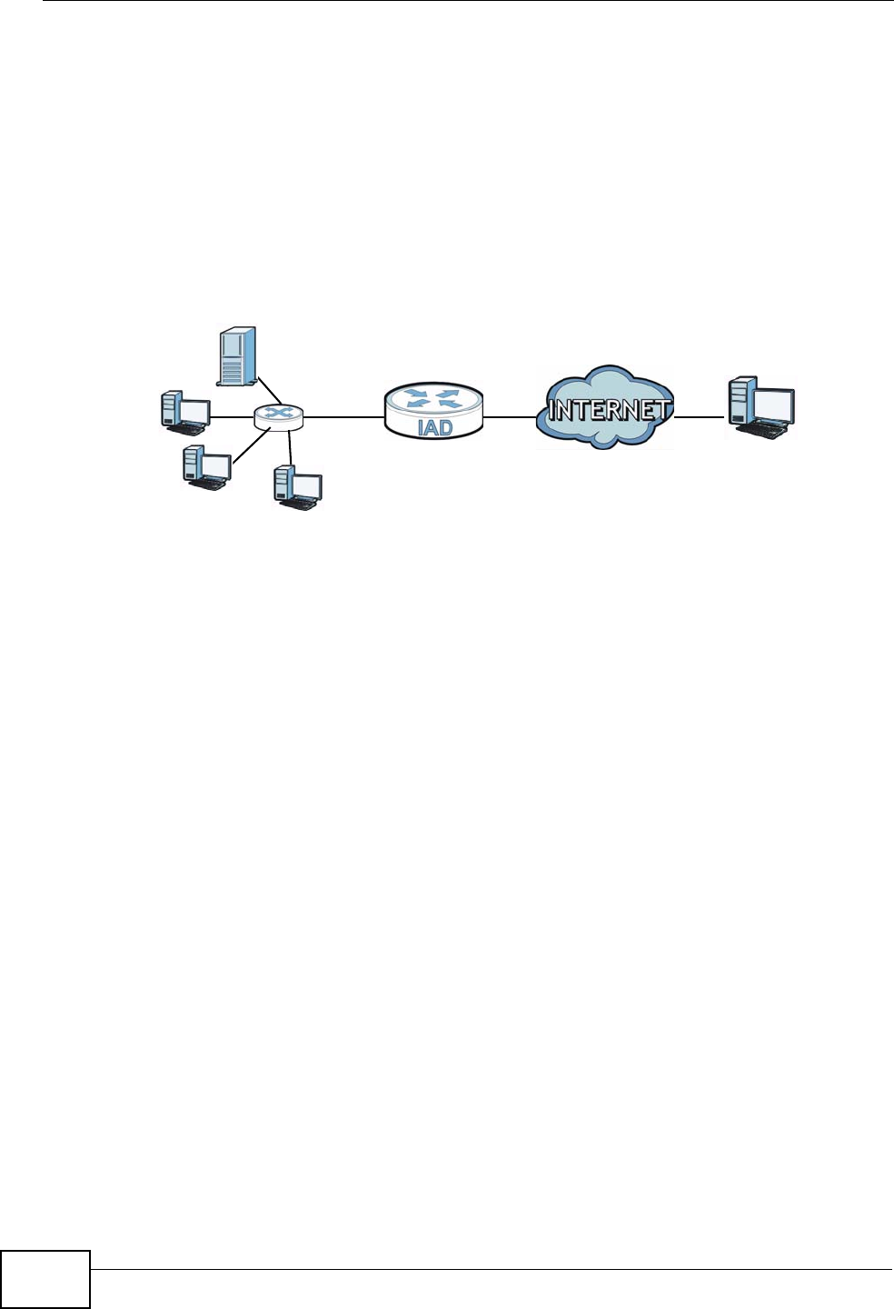
Chapter 3 Tutorials
P-2612HNU-Fx User’s Guide
50
3.4 Setting Up NAT Port Forwarding
In this tutorial, you manage the Doom server on a computer behind the ZyXEL
Device. In order for players on the Internet (like Ain the figure below) to
communicate with the Doom server, you need to configure the port settings and IP
address on the ZyXEL Device. Traffic should be forwarded to the port 666 of the
Doom server computer which has an IP address of 192.168.1.34.
Tutorial: NAT Port Forwarding Setup
You may set up the port settings by configuring the port settings for the Doom
server computer (see Chapter 11 on page 200 for more information).
1Click Network Setting > NAT > Port Forwarding. Click Add new rule.
D=192.168.1.34 WAN
LAN
port 666
A
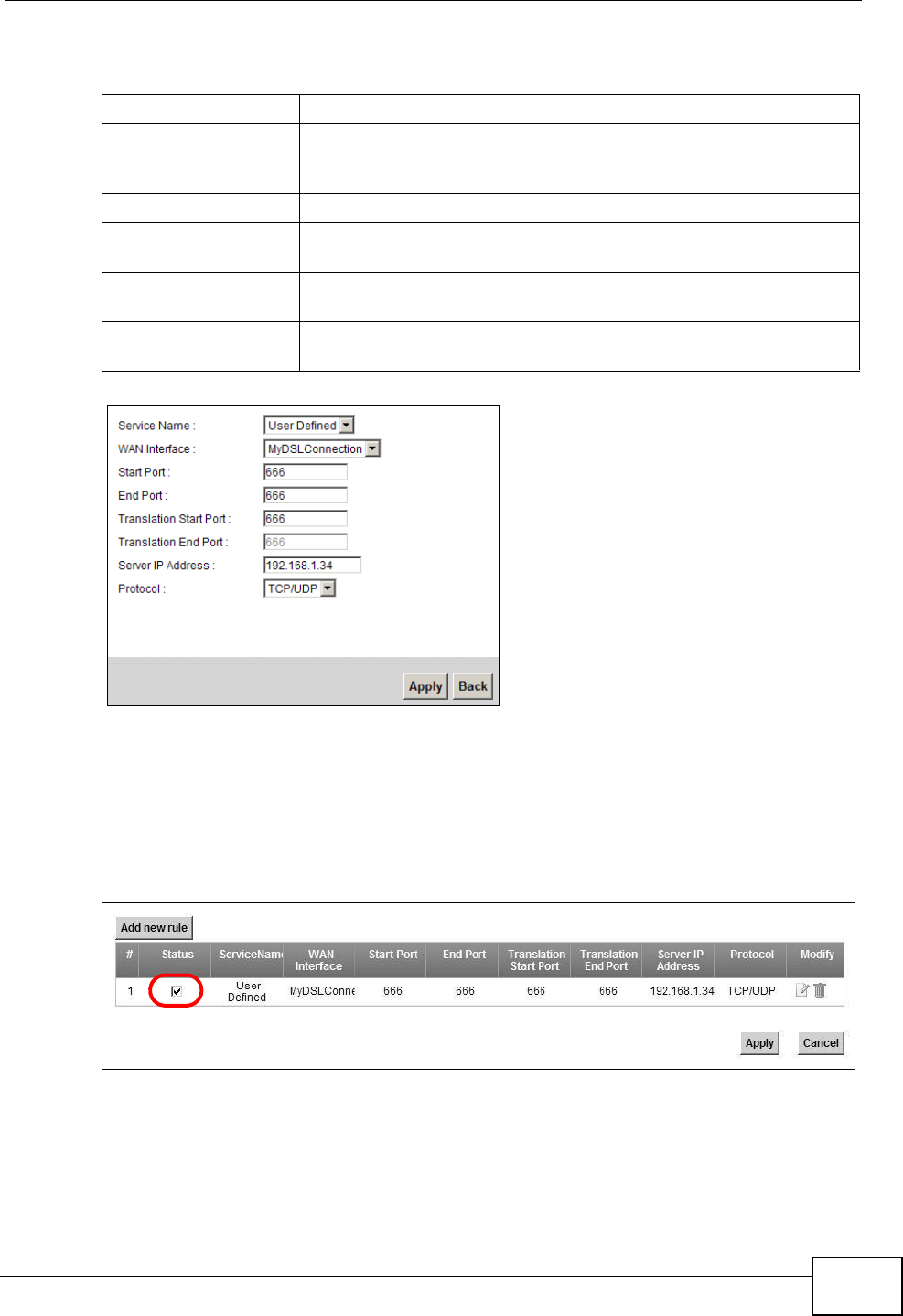
Chapter 3 Tutorials
P-2612HNU-Fx User’s Guide 51
2Enter the following values:
3Click Apply.
4The port forwarding settings you configured should appear in the table. Make sure
the Status check box for this rule is selected. Click Apply to have the ZyXEL
Device start forwarding port 666 traffic to the computer with IP address
192.168.1.34.
Players on the Internet then can have access to your Doom server.
Service Name Select User Defined.
WAN Interface Select the WAN interface through which the Doom service is
forwarded. This is the default interface for this example, which is
MyDSLConnection.
Start/End Ports 666
Translation Start/End
Ports
666
Server IP Address Enter the IP address of the Doom server. This is 192.168.1.34
for this example.
Protocol Select TCP/UDP. This should be the protocol supported by the
Doom server.

Chapter 3 Tutorials
P-2612HNU-Fx User’s Guide
52
3.5 How to Make a VoIP Call
You can register a SIP account with the SIP server and make voice calls over the
Internet to another VoIP device.
The following parameters are used in this example:
3.5.1 VoIP Calls With a Registered SIP Account
To use a registered SIP account, you should configure the SIP service provider and
applied for a SIP account.
3.5.1.1 SIP Service Provider Configuration
Follow the steps below to configure your SIP service provider.
1Make sure your ZyXEL Device is connected to the Internet.
2Open the web configurator.
3Click VoIP > SIP to open the SIP Service Provider screen. Select Add New
from the Service Provider Selection drop-down list box.
SIP Service Provider Name ServiceProvider1
SIP Account Number 12345678
Username ChangeMe
Password ThisIsMySIP
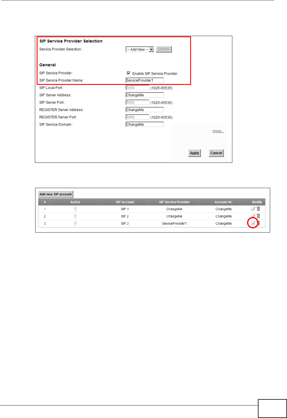
Chapter 3 Tutorials
P-2612HNU-Fx User’s Guide 53
4Select the Enable check box of SIP Service Provider and enter the SIP Service
Provider Name.
5Go to the SIP Account screen, click the Edit icon of SIP 3.
6Select the Active SIP Account check box, then enter the SIP Account Number,
Username, and Password. Leave other settings as default.
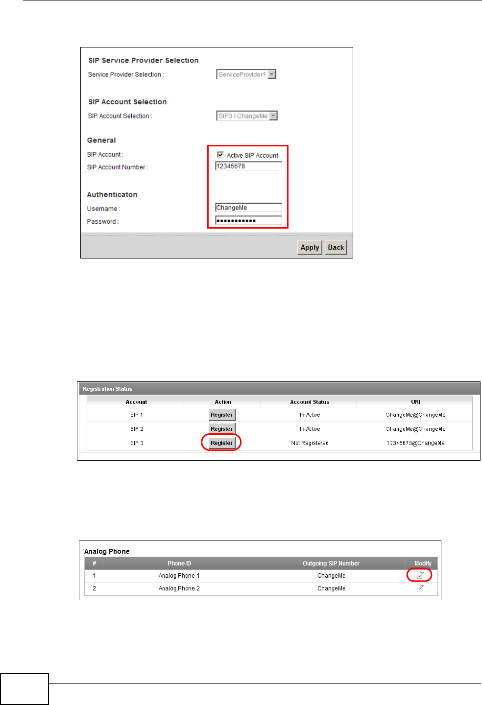
Chapter 3 Tutorials
P-2612HNU-Fx User’s Guide
54
7Click Apply to save your settings.
3.5.1.2 SIP Account Registration
Follow the steps below to register and activate your SIP account.
1Click Connection Status > System Info to check if your SIP account has been
registered successfully. If the status is Not Registered, check your Internet
connection and click Register to register your SIP account.
Tutorial: Registration Status
3.5.1.3 Analog Phone Configuration
1Click VoIP > Phone to open the Phone Device screen. Click the Edit icon next
to Analog Phone 1 to configure the first phone port.
2Select SIP 3 from the SIP Account in the SIP Account to Make Outgoing Call
section to have the phone (connected to the first phone port) use the registered
SIP 3 account to make outgoing calls.
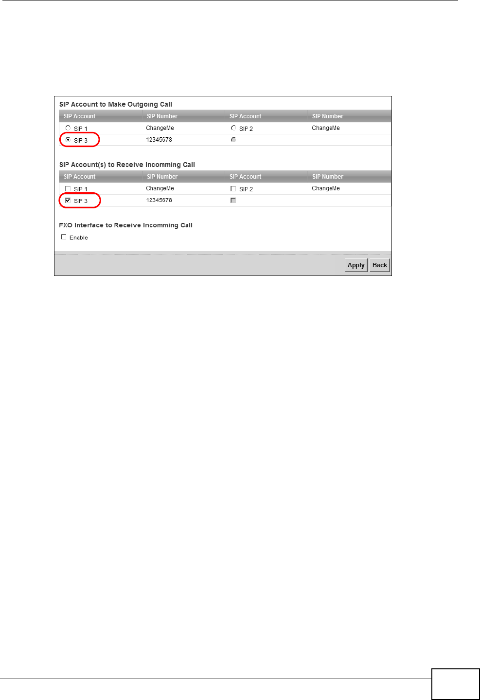
Chapter 3 Tutorials
P-2612HNU-Fx User’s Guide 55
3Select the SIP 3 check box in the SIP Account(s) to Receive Incoming Call
section to have the phone (connected to the first phone port) receive phone calls
for the SIP 3 account.
4Click Apply to save your changes.
Tutorial: VoIP > Phone
3.5.1.4 Making a VoIP Call
1Make sure you connect a telephone to the first phone port on the ZyXEL Device.
2Make sure the ZyXEL Device is on and connected to the Internet.
3Pick up the phone receiver.
4Dial the VoIP phone number you want to call.
3.6 Using the File Sharing Feature
In this section you can:
• Set up file sharing of your USB device from the ZyXEL Device
• Access the shared files of your USB device from a computer
3.6.1 Set Up File Sharing
To set up file sharing you need to connect your USB device, enable file sharing and
set up your share(s).
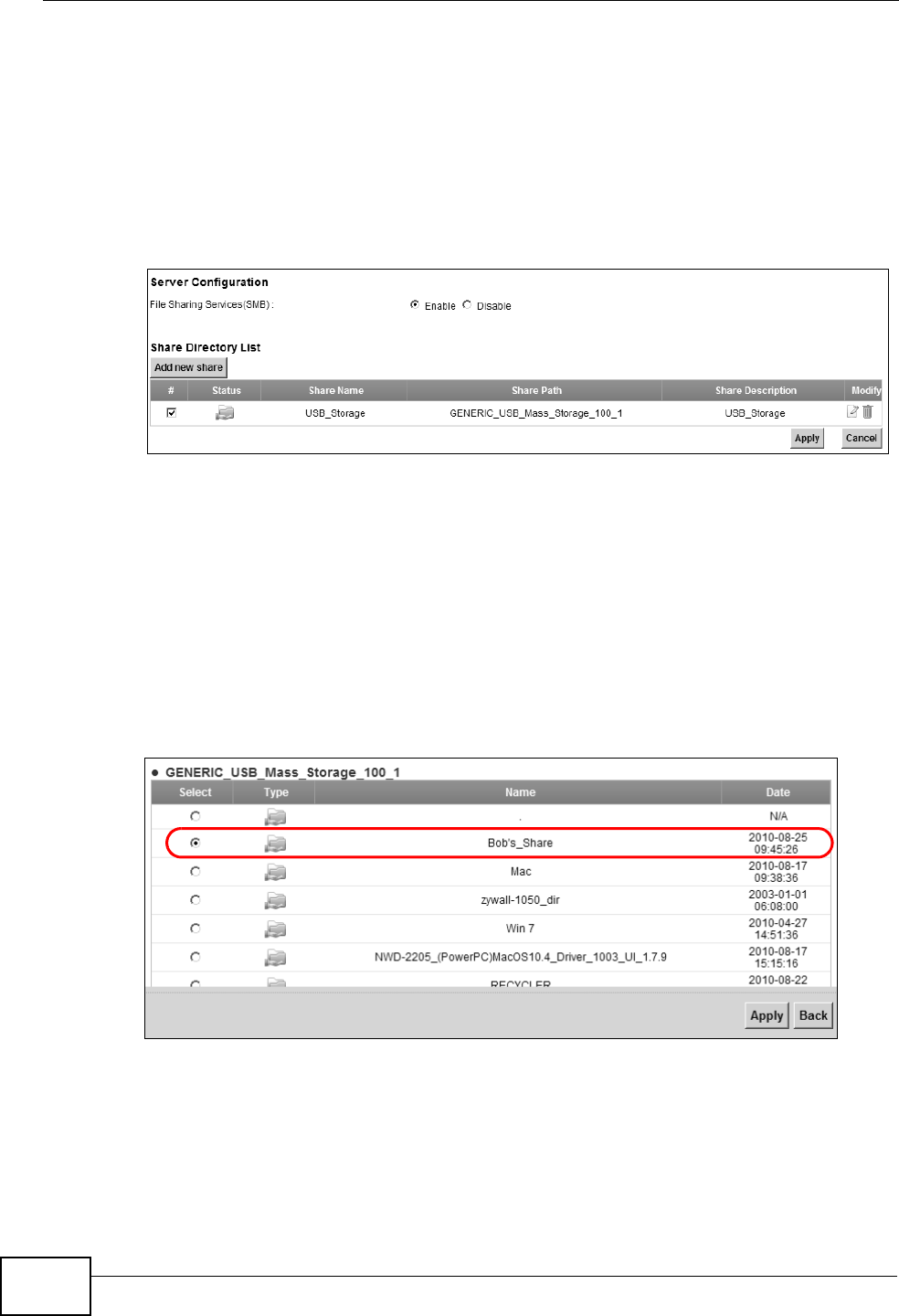
Chapter 3 Tutorials
P-2612HNU-Fx User’s Guide
56
3.6.1.1 Activate File Sharing
1Connect your USB device to one of the USB ports at the back panel of the ZyXEL
Device.
2Click Network Setting > Home Networking > File Sharing. Select Enable
and click Apply to activate the file sharing function. The ZyXEL Device
automatically adds your USB device to the Share Directory List.
3.6.1.2 Set up File Sharing on Your ZyXEL Device
You also need to set up file sharing on your ZyXEL Device in order to share files.
1Click Add new share in the File Sharing screen to configure a new share. Select
your USB device from the Volume drop-down list box.
2Click Browse to browse through all the files on your USB device. Select the folder
that you want to add as a share. In this example, select Bob’s_Share. Click
Apply.
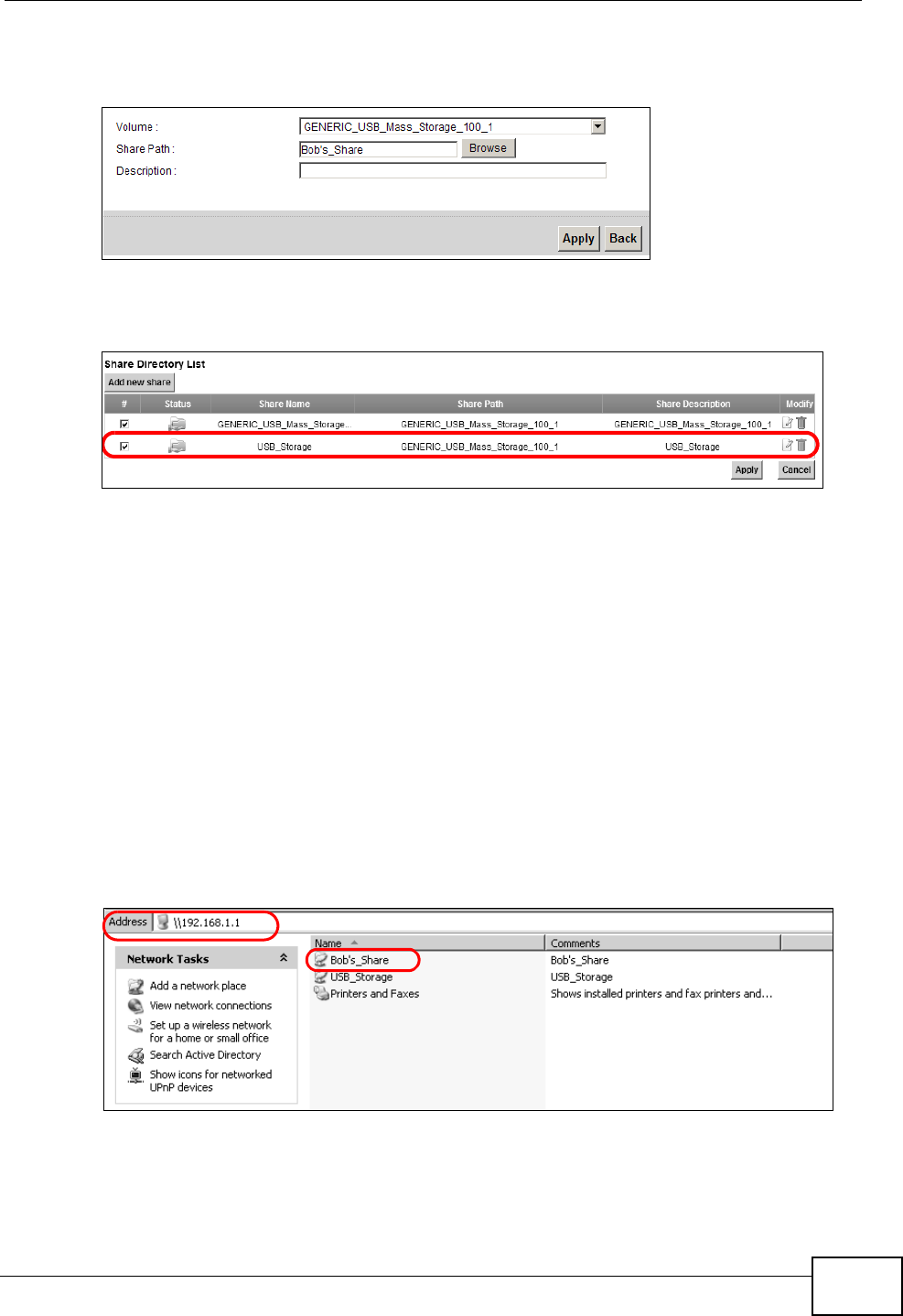
Chapter 3 Tutorials
P-2612HNU-Fx User’s Guide 57
3You can add a description for the share or leave it blank. The Add Share
Directory screen should look like the following.Click Apply to finish.
Tutorial: USB Services > File Sharing > Share Configuration
4This sets up the file sharing server. You can see the USB storage device listed in
the table below.
Tutorial: USB Services > File Sharing > Share Configuration (2)
3.6.2 Access Your Shared Files From a Computer
You can use Windows Explorer to access the file storage devices connected to the
ZyXEL Device.
Note: The examples in this User’s Guide show you how to use Microsoft’s Windows
XP to browse your shared files. Refer to your operating system’s
documentation for how to browse your file structure.
Open Windows Explorer to access Bob’s Share using Windows Explorer browser.
In Windows Explorer’s Address bar type a double backslash “\\” followed by the IP
address of the ZyXEL Device (the default IP address of the ZyXEL Device is
192.168.1.1) and press [ENTER]. The share folder Bob’s_Share is available.
File Sharing via Windows Explore r
Once you access Bob’s_Share via your ZyXEL Device, you do not have to relogin
unless you restart your computer.
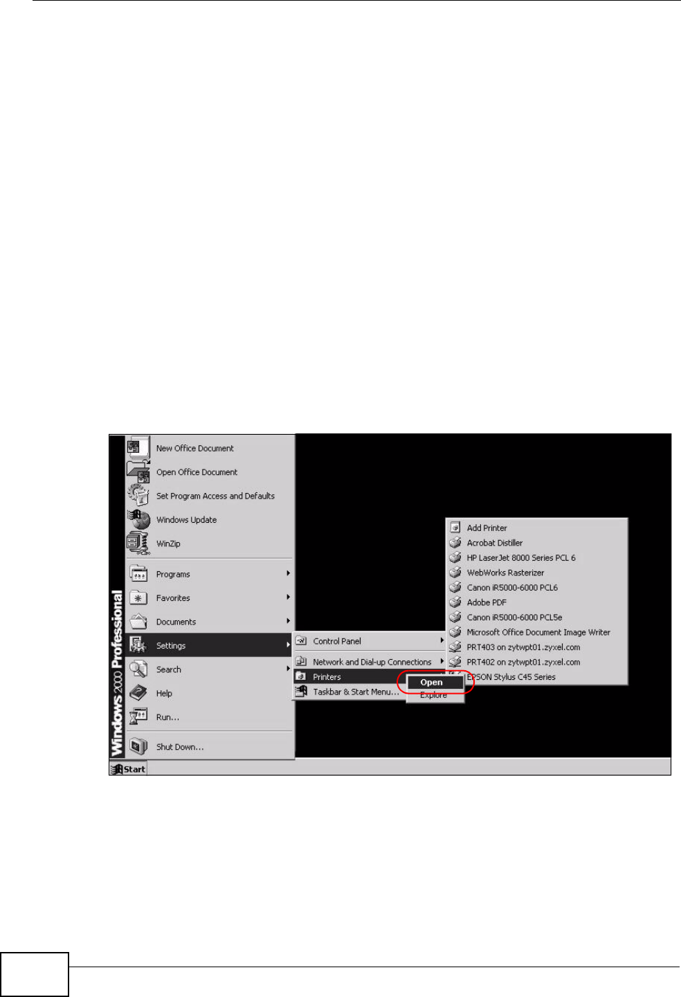
Chapter 3 Tutorials
P-2612HNU-Fx User’s Guide
58
3.7 Using the Print Server Feature
In this section you can:
• Configure a TCP/IP Printer Port
• Add a New Printer Using Windows
• Add a New Printer Using Macintosh OS X
Configure a TCP/IP Printer Port
This example shows how you can configure a TCP/IP printer port. This example is
done using the Windows 2000 Professional operating system. Some menu items
may look different on your operating system. The TCP/IP port must be configured
with the IP address of the ZyXEL Device and must use the RAW protocol to
communicate with the printer. Consult your operating systems documentation for
instructions on how to do this or follow the instructions below if you have a
Windows 2000/XP operating system.
1Click Start > Settings, then right click on Printers and select Open.
Tutorial: Open Printers Window
The Printers folder opens up. First you need to open up the properties windows
for the printer you want to configure a TCP/IP port.
2Locate your printer.
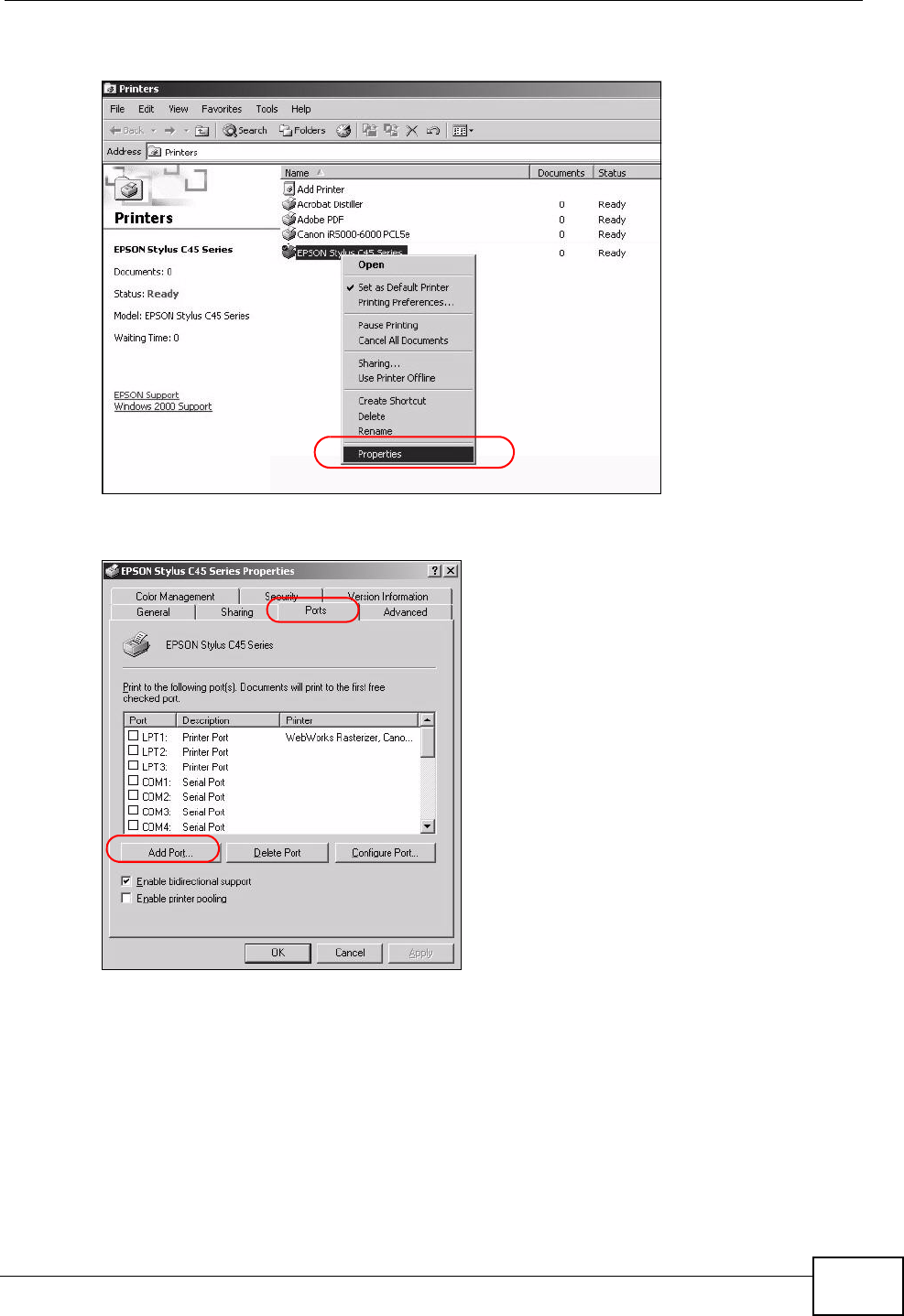
Chapter 3 Tutorials
P-2612HNU-Fx User’s Guide 59
3Right click on your printer and select Properties.
Tutorial: Open Printer Properties
4Select the Ports tab and click Add Port...
Tutorial: Printer Properties Window
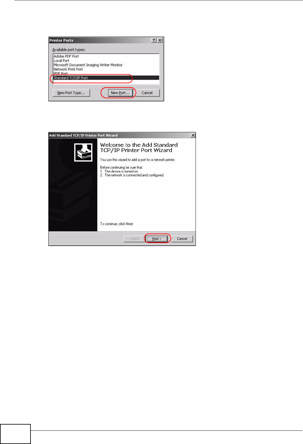
Chapter 3 Tutorials
P-2612HNU-Fx User’s Guide
60
5A Printer Ports window appears. Select Standard TCP/IP Port and click New
Port...
Tutorial: Add a Port Window
6Add Standard TCP/IP Printer Port Wizard window opens up. Click Next to
start configuring the printer port.
Tutorial: Add a Port Wizard
7Enter the IP address of the ZyXEL Device to which the printer is connected in the
Printer Name or IP Address: field. In our example we use the default IP
address of the ZyXEL Device, 192.168.1.1. The Port Name field updates
automatically to reflect the IP address of the port. Click Next.
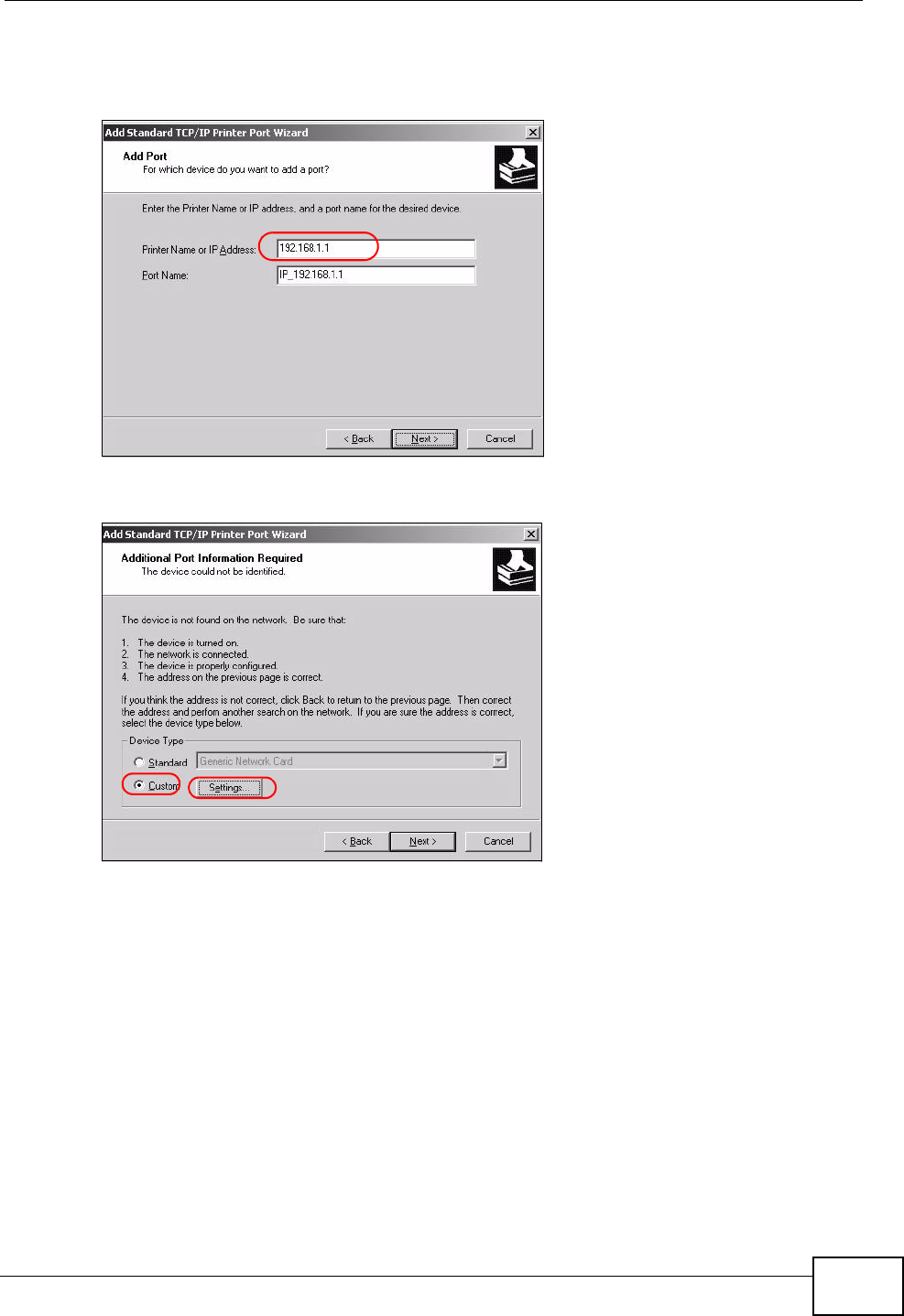
Chapter 3 Tutorials
P-2612HNU-Fx User’s Guide 61
Note: The computer from which you are configuring the TCP/IP printer port must be
on the same LAN in order to use the printer sharing function.
Tutorial: Enter IP Address of the ZyXEL De vice
8Select Custom under Device Type and click Settings.
Tutorial: Custom Port Settings
9Confirm the IP address of the ZyXEL Device in the IP Address field.
10 Select Raw under Protocol.
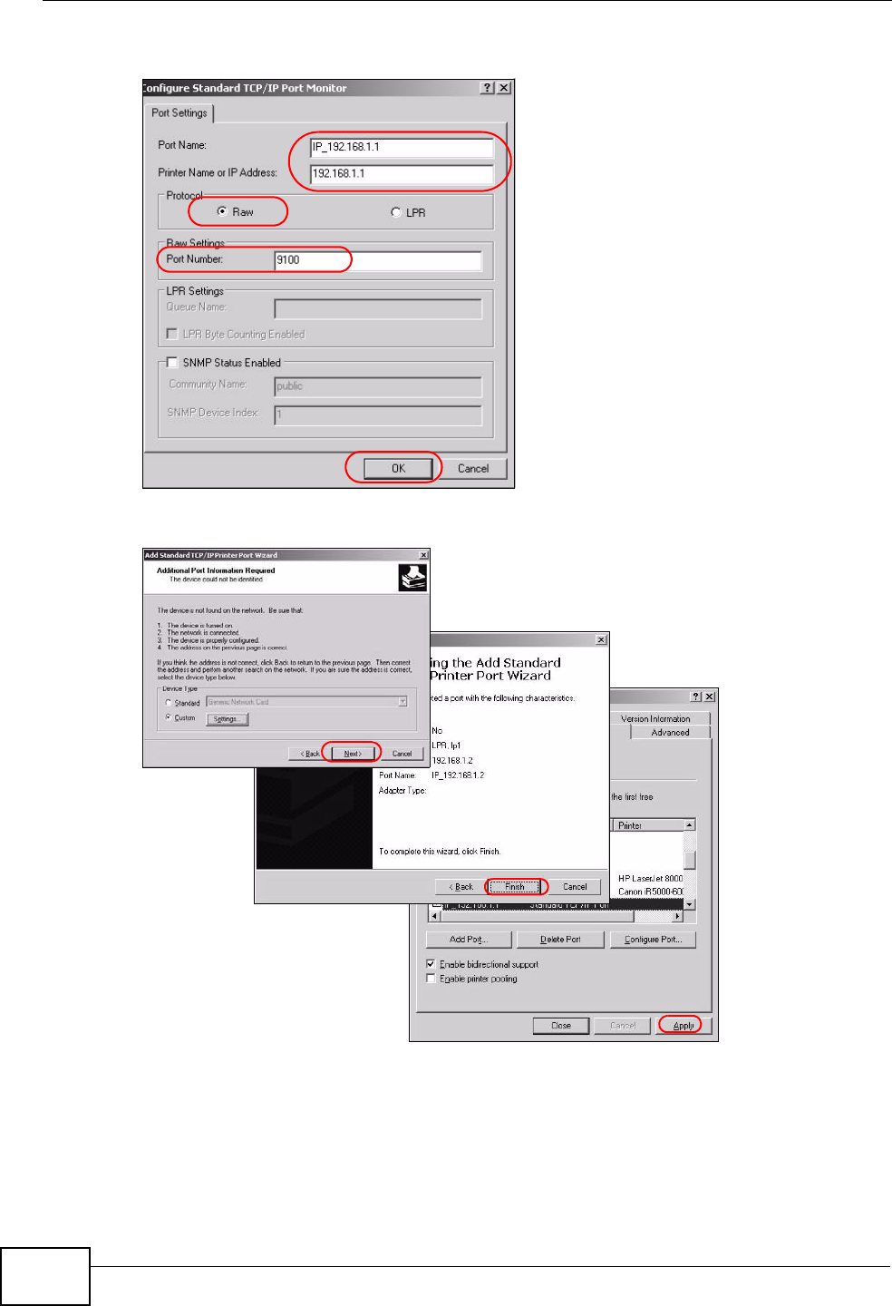
Chapter 3 Tutorials
P-2612HNU-Fx User’s Guide
62
11 The Port Number is automatically configured as 9100. Click OK.
Tutorial: Custom Port Settings
12 Continue through the wizard, apply your settings and close the wizard window.
Tutorial: Finish Adding the TCP/IP Port
13 Repeat steps 1 to 12 to add this printer to other computers on your network.
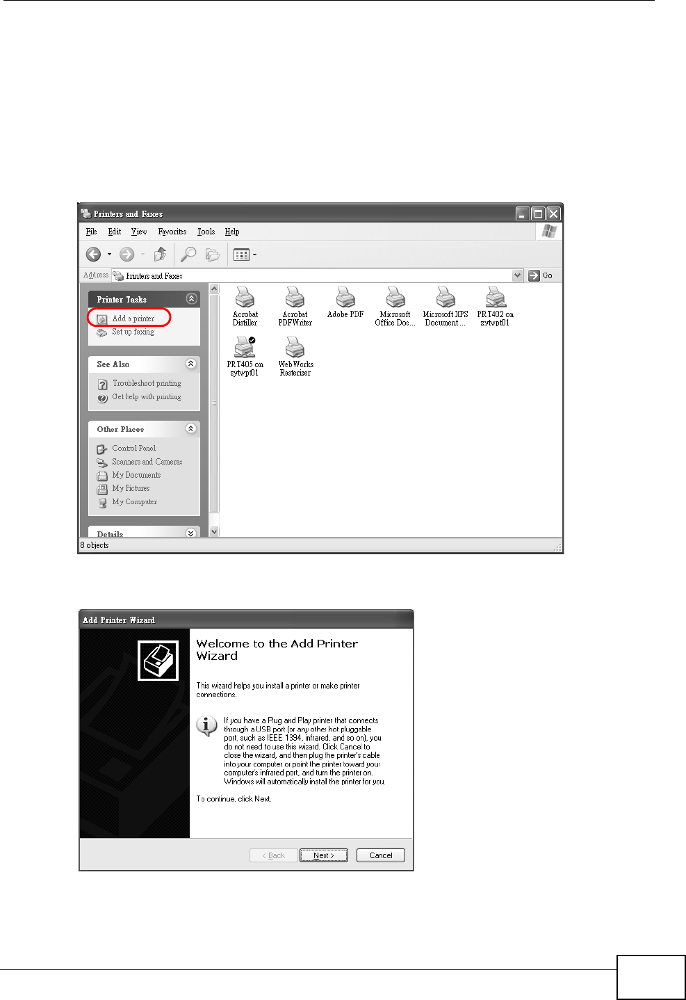
Chapter 3 Tutorials
P-2612HNU-Fx User’s Guide 63
Add a New Printer Using Windows
This example shows how to connect a printer to your ZyXEL Device using the
Windows XP Professional operating system. Some menu items may look different
on your operating system.
1Click Start > Control Panel >Printers and Faxes to open the Printers and
Faxes screen. Click Add a Printer.
Tutorial: Printers Folder
2The Add Printer Wizard screen displays. Click Next.
Tutorial: Add Printer Wizard: Welcome
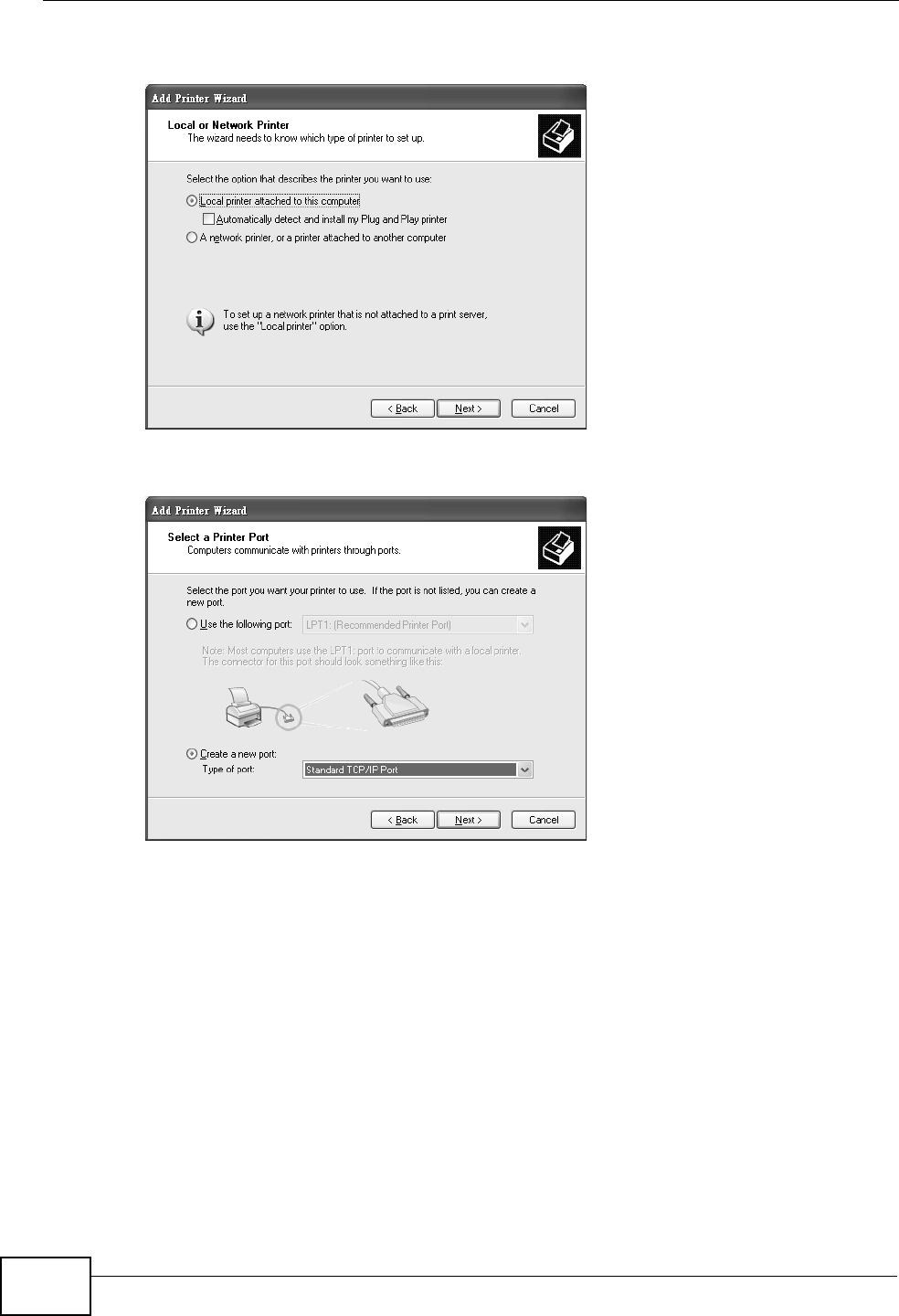
Chapter 3 Tutorials
P-2612HNU-Fx User’s Guide
64
3Select Local printer attached to this computer and click Next.
Tutorial: Add Printer Wizard: Local or Ne twork Printer
4Select Create a new port and Standard TCP/IP Port. Click Next.
Tutorial: Add Printer Wizard: Select the Printer Port
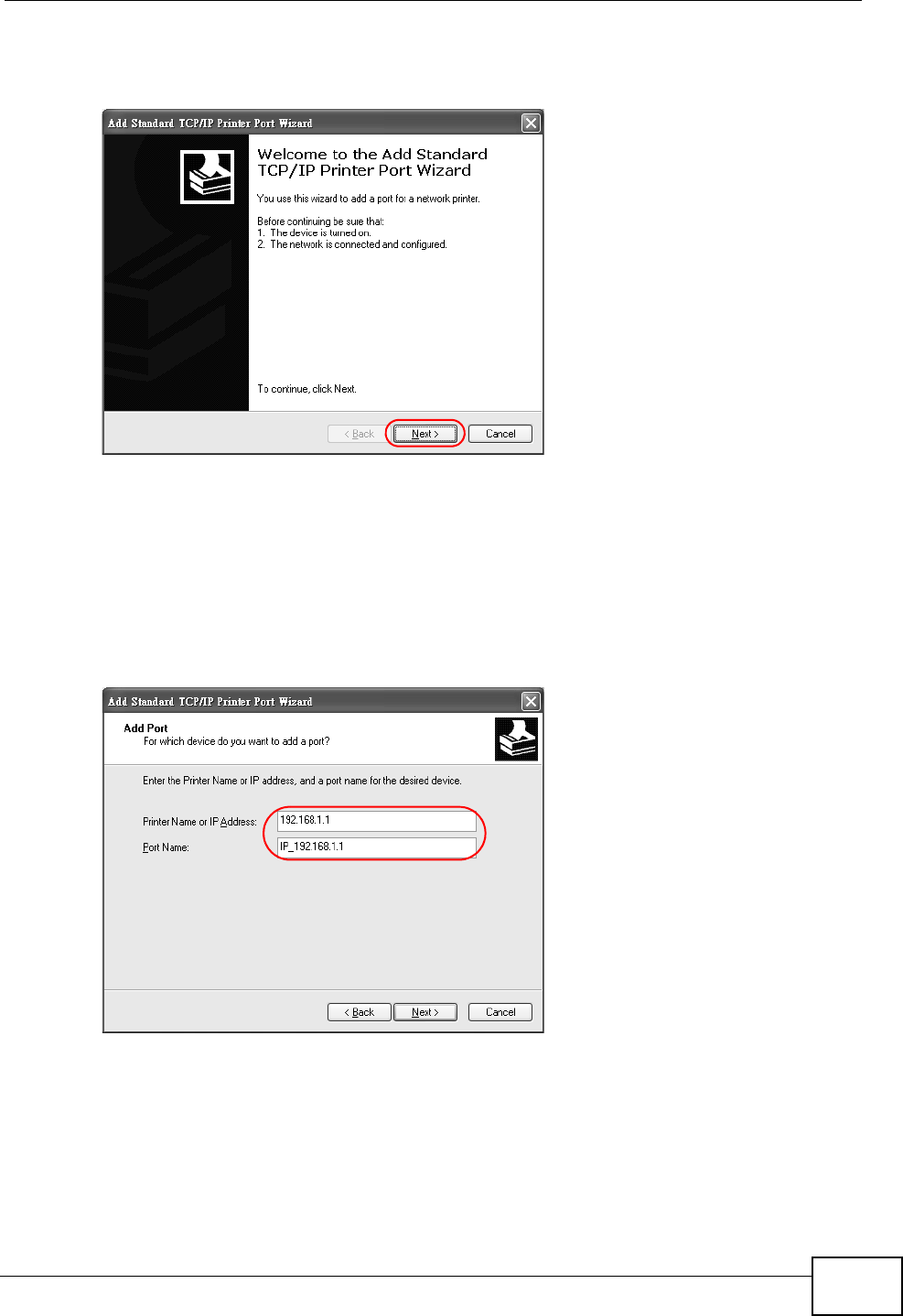
Chapter 3 Tutorials
P-2612HNU-Fx User’s Guide 65
5Add Standard TCP/IP Printer Port Wizard window opens up. Click Next to
start configuring the printer port.
Tutorial: Add a Port Wizard
6Enter the IP address of the ZyXEL Device to which the printer is connected in the
Printer Name or IP Address: field. In our example we use the default IP
address of the ZyXEL Device, 192.168.1.1. The Port Name field updates
automatically to reflect the IP address of the port. Click Next.
Note: The computer from which you are configuring the TCP/IP printer port must be
on the same LAN in order to use the printer sharing function.
Tutorial: Enter IP Address of the ZyXEL De vice
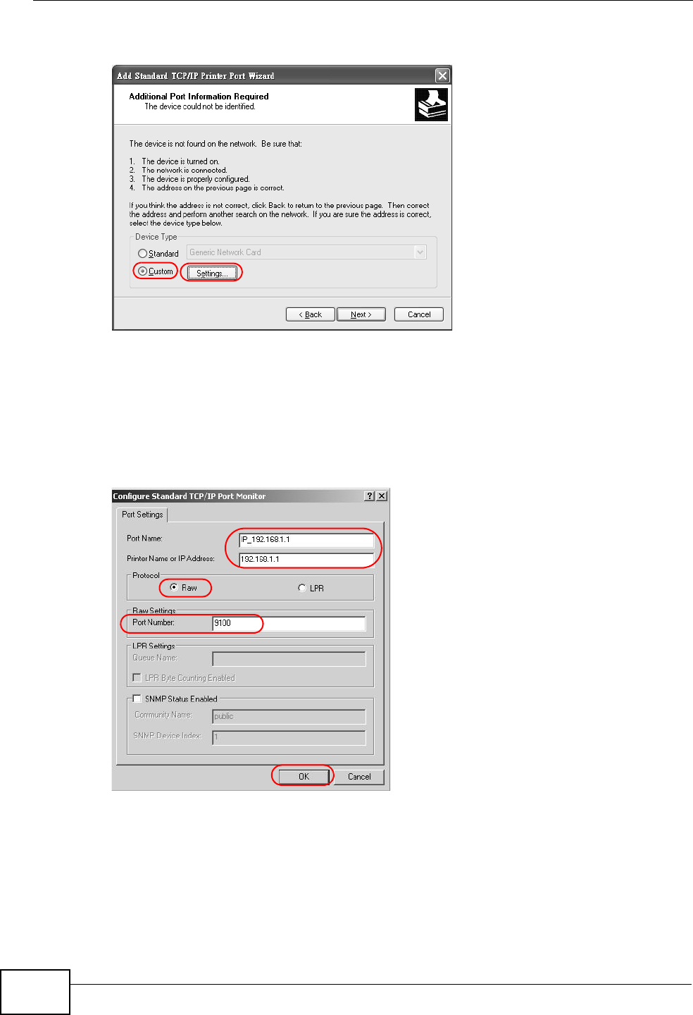
Chapter 3 Tutorials
P-2612HNU-Fx User’s Guide
66
7Select Custom under Device Type and click Settings.
Tutorial: Custom Port Settings
8Confirm the IP address of the ZyXEL Device in the Printer Name or IP Address
field.
9Select Raw under Protocol.
10 The Port Number is automatically configured as 9100. Click OK to go back to
the previous screen and click Next.
Tutorial: Custom Port Settings
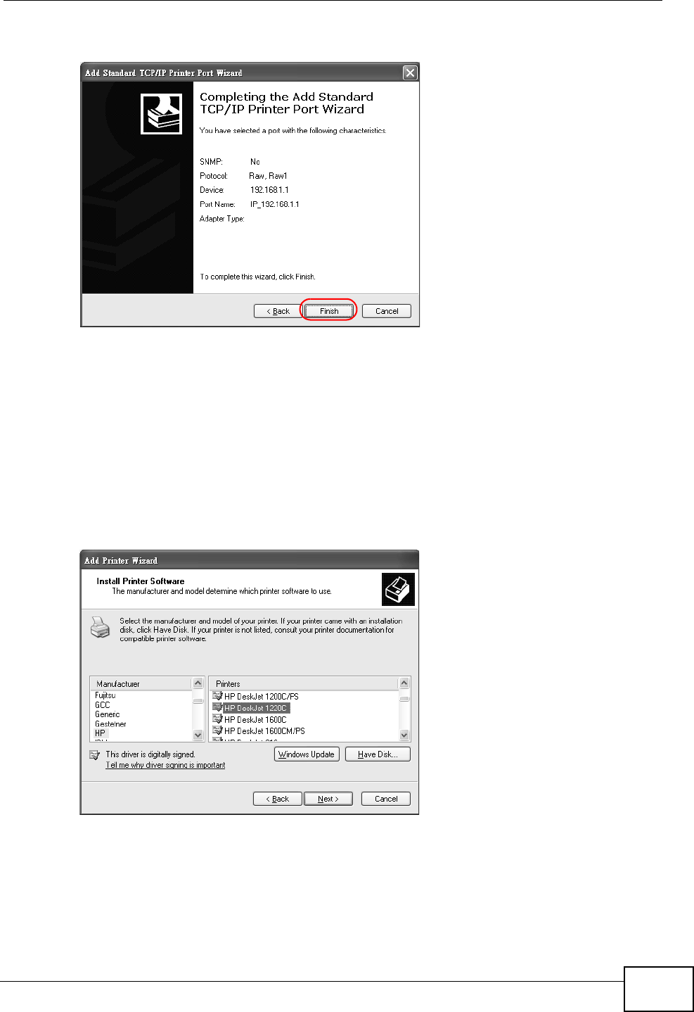
Chapter 3 Tutorials
P-2612HNU-Fx User’s Guide 67
11 Click Finish to close the wizard window.
Tutorial: Finish Adding the TCP/IP Port
12 Select the make of the printer that you want to connect to the print server in the
Manufacturer list of printers.
13 Select the printer model from the list of Printers.
14 If your printer is not displayed in the list of Printers, you can insert the printer
driver installation CD/disk or download the driver file to your computer, click Have
Disk… and install the new printer driver.
15 Click Next to continue.
Tutorial: Add Printer Wizard: Printer Driv er
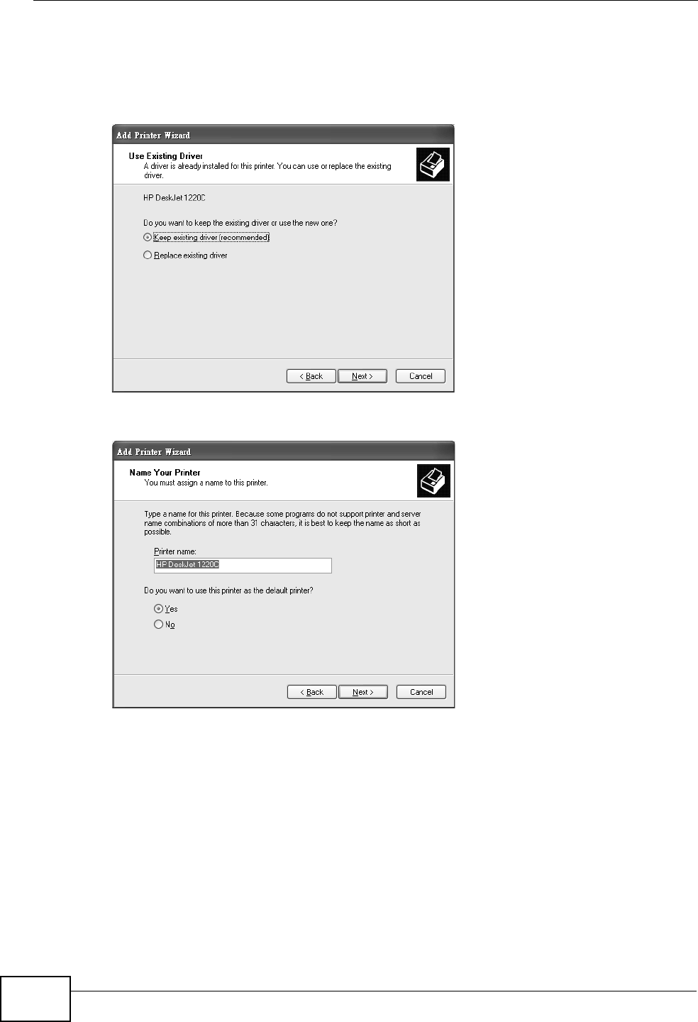
Chapter 3 Tutorials
P-2612HNU-Fx User’s Guide
68
16 If the following screen displays, select Keep existing driver radio button and
click Next if you already have a printer driver installed on your computer and you
do not want to change it. Otherwise, select Replace existing driver to replace it
with the new driver you selected in the previous screen and click Next.
Tutorial: Add Printer Wizard: Use Existin g Driver
17 Type a name to identify the printer and then click Next to continue.
Tutorial: Add Printer Wizard: Name Your Printer
18 The ZyXEL Device is a print server itself and you do not need to have your
computer act as a print server by sharing the printer with other users in the same
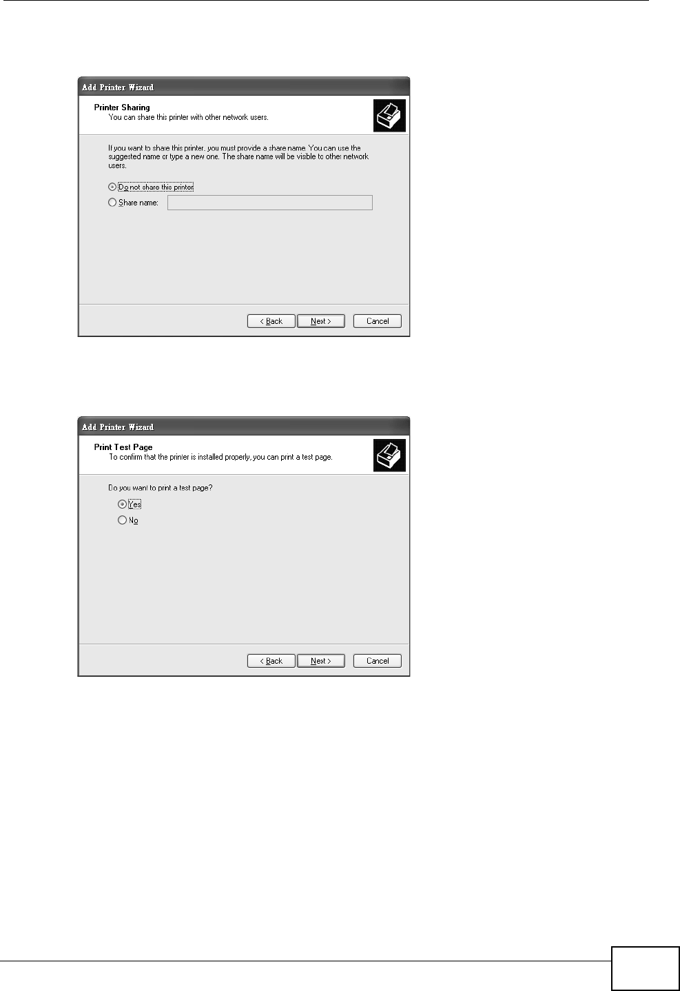
Chapter 3 Tutorials
P-2612HNU-Fx User’s Guide 69
network; just select Do not share this printer and click Next to proceed to the
following screen.
Tutorial: Add Printer Wizard: Printer Sharin g
19 Select Yes and then click the Next button if you want to print a test page. A pop-
up screen displays to ask if the test page printed correctly. Otherwise select No
and then click Next to continue.
Tutorial: Add Printer Wizard: Print Test Page
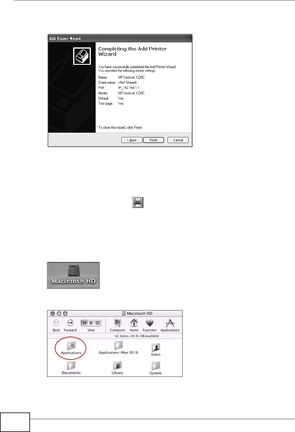
Chapter 3 Tutorials
P-2612HNU-Fx User’s Guide
70
20 The following screen shows your current printer settings. Select Finish to
complete adding a new printer.
Tutorial: Add Printer Wizard Complete
Add a New Printer Using Macintosh OS X
Complete the following steps to set up a print server driver on your Macintosh
computer.
1Click the Print Center icon located in the Macintosh Dock (a place holding a
series of icons/shortcuts at the bottom of the desktop). Proceed to step 6 to
continue. If the Print Center icon is not in the Macintosh Dock, proceed to the
next step.
2On your desktop, double-click the Macintosh HD icon to open the Macintosh HD
window.
Tutorial: Macintosh HD
3Double-click the Applications folder.
Tutorial: Macintosh HD folder
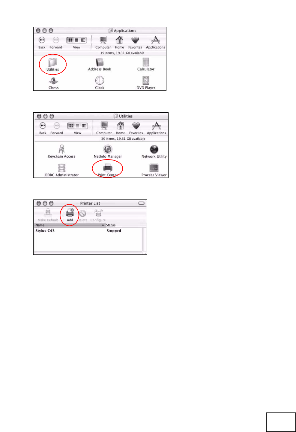
Chapter 3 Tutorials
P-2612HNU-Fx User’s Guide 71
4Double-click the Utilities folder.
Tutorial: Applications Folder
5Double-click the Print Center icon.
Tutorial: Utilities Folder
6Click the Add icon at the top of the screen.
Tutorial: Printer List Folder
7Set up your printer in the Printer List configuration screen. Select IP Printing
from the drop-down list box.
8In the Printer’s Address field, type the IP address of your ZyXEL Device.
9Deselect the Use default queue on server check box.
10 Type LP1 in the Queue Name field.
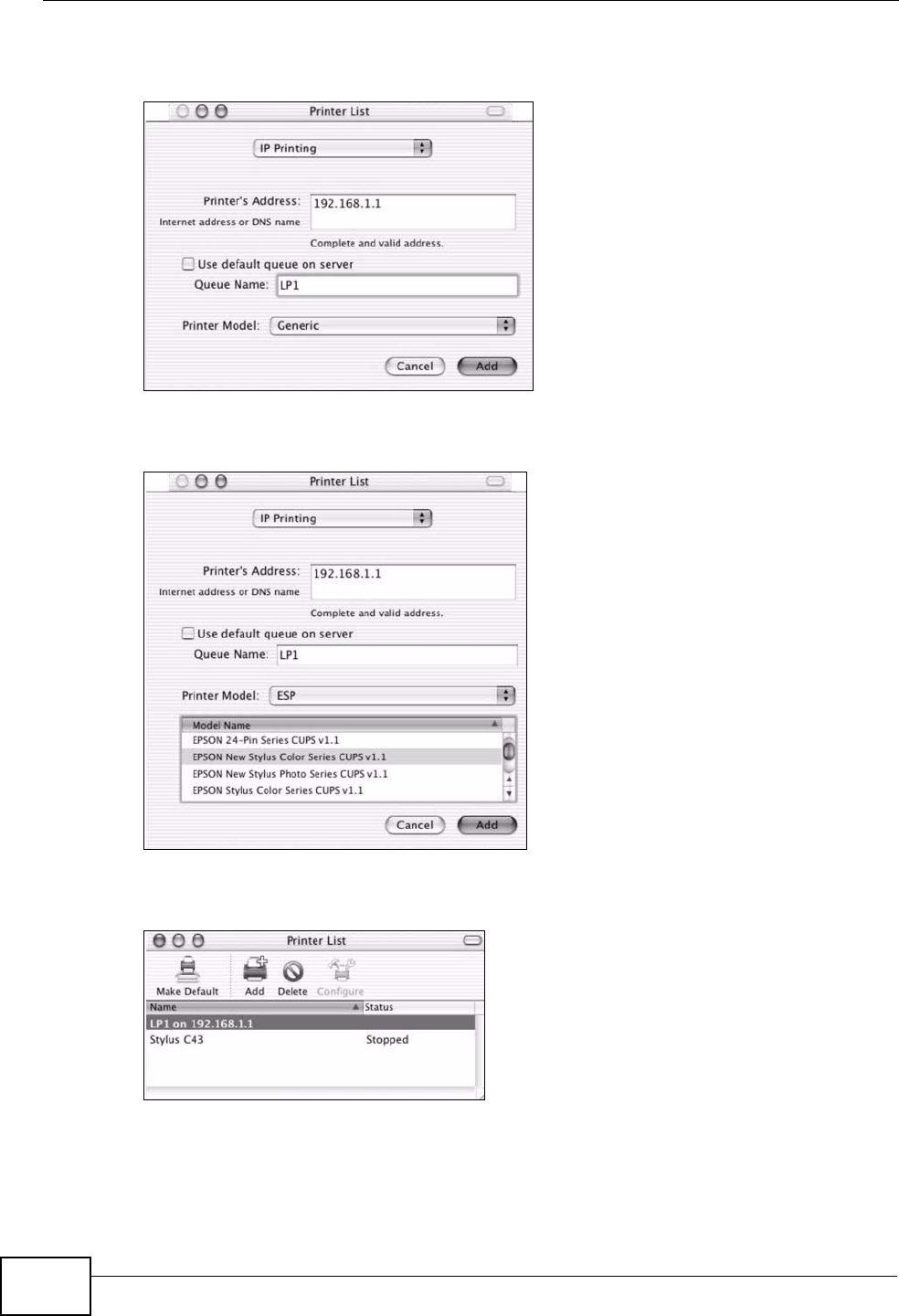
Chapter 3 Tutorials
P-2612HNU-Fx User’s Guide
72
11 Select your Printer Model from the drop-down list box. If the printer's model is
not listed, select Generic.
Tutorial: Printer Configuration
12 Click Add to select a printer model, save and close the Printer List configuration
screen.
Tutorial: Printer Model
13 The name LP1 on 192.168.1.1 displays in the Printer List field. The default
printer Name displays in bold type.
Tutorial: Print Server
Your Macintosh print server driver setup is complete. You can now use the ZyXEL
Device’s print server to print from a Macintosh computer.
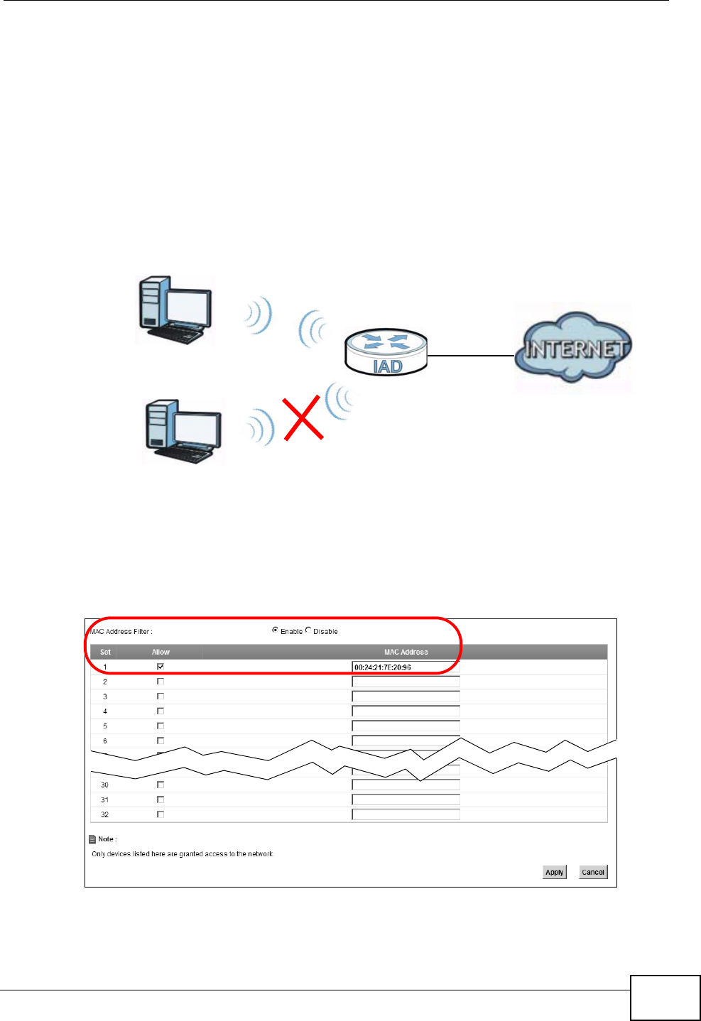
Chapter 3 Tutorials
P-2612HNU-Fx User’s Guide 73
3.8 Configuring the MAC Address Filter
Thomas noticed that his daughter Josephine spends too much time surfing the
web and downloading media files. He decided to prevent Josephine from accessing
the Internet so that she can concentrate on preparing for her final exams.
Josephine’s computer connects wirelessly to the Internet through the ZyXEL
Device. Thomas decides to use the Security > MAC Filter screen to grant
wireless network access to his computer but not to Josephine’s computer.
1Click Security > MAC Filter to open the MAC Filter screen. Select the Enable
check box to activate MAC filter fuction.
2Find the MAC address of Thomas’ computer in this screen. Select Allow. Click
Apply.
Thomas
Josephine
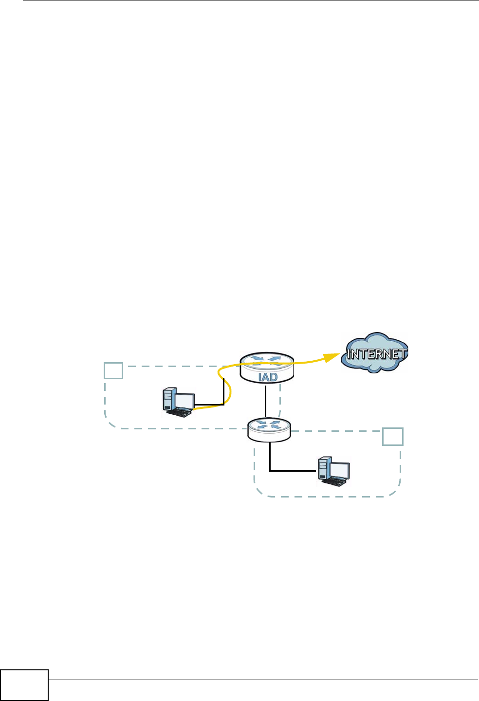
Chapter 3 Tutorials
P-2612HNU-Fx User’s Guide
74
Thomas can also grant access to the computers of other members of his family
and friends. However, Josephine and others not listed in this screen will no longer
be able to access the Internet through the ZyXEL Device.
3.9 Configuring Static Route for Routing to
Another Network
In order to extend your Intranet and control traffic flowing directions, you may
connect a router to the ZyXEL Device’s LAN. The router may be used to separate
two department networks. This tutorial shows how to configure a static routing
rule for two network routings.
In the following figure, router Ris connected to the ZyXEL Device’s LAN. R
connects to two networks, N1 (192.168.1.x/24) and N2 (192.168.10.x/24). If
you want to send traffic from computer A (in N1 network) to computer B (in N2
network), the traffic is sent to the ZyXEL Device’s WAN default gateway by
default. In this case, B will never receive the traffic.
You need to specify a static routing rule on the ZyXEL Device to specify R as the
router in charge of forwarding traffic to N2. In this case, the ZyXEL Device routes
N2
B
N1
A
R
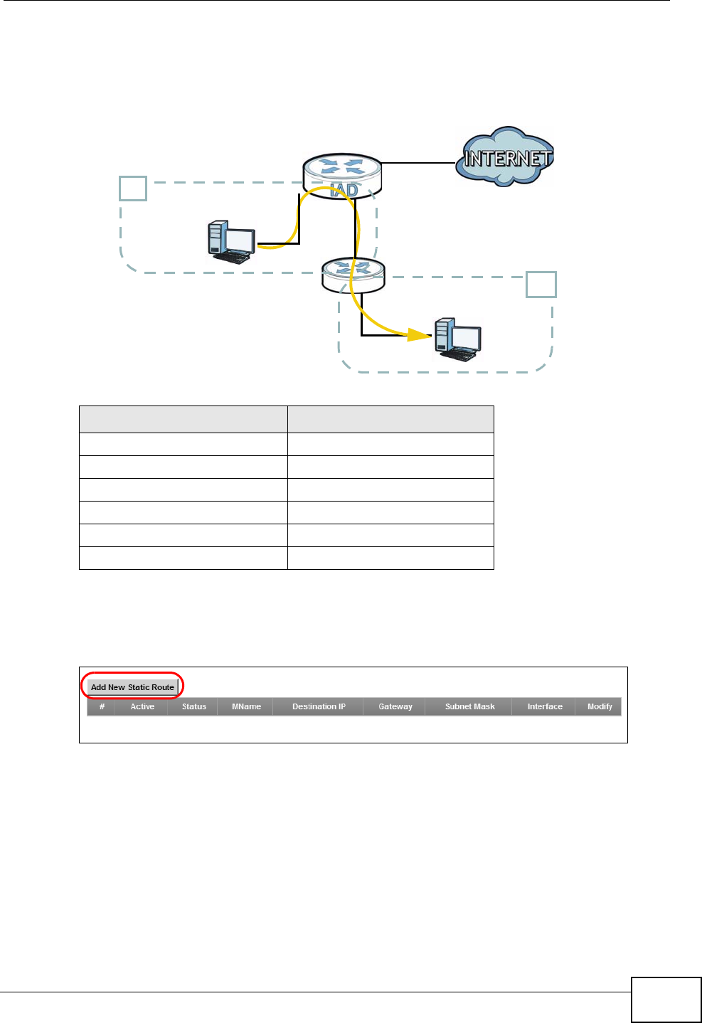
Chapter 3 Tutorials
P-2612HNU-Fx User’s Guide 75
traffic from A to R and then R routes the traffic to B.This tutorial uses the
following example IP settings:
To configure a static route to route traffic from N1 to N2:
1Click Network Setting > Routing. Click Add New Static Route.
2Configure the Static Route Setup screen using the following settings:
• Select Active.
• Specify a descriptive name for this routing rule.
• Type 192.168.10.0 and subnet mask 255.255.255.0 for the destination, N2.
Table 3 IP Settings in this Tutorial
DEVICE / COMPUTER IP ADDRESS
The ZyXEL Device’s WAN 172.16.1.1
The ZyXEL Device’s LAN 192.168.1.1
A192.168.1.34
R’s N1 192.168.1.253
R’s N2 192.168.10.2
B192.168.10.33
N2
B
N1
A
R
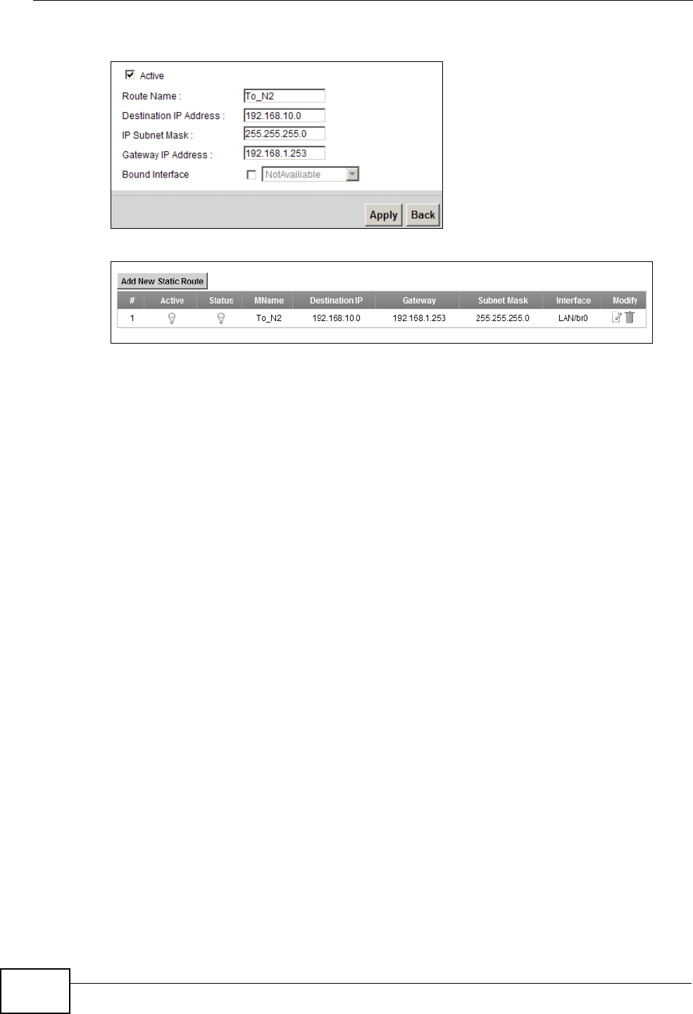
Chapter 3 Tutorials
P-2612HNU-Fx User’s Guide
76
• Type 192.168.1.253 (R’s N1 address) in the Gateway IP Address field.
Click Apply. The Routing screen should display the route you just added.
Now B should be able to receive traffic from A. You may need to additionally
configure B’s firewall settings to allow specific traffic to pass through.
3.10 Configuring QoS Queue and Class Setup
This section contains tutorials on how you can configure the QoS screen.
Note: Voice traffic will not be affected by the user-defined QoS settings on the ZyXEL
Device. It always gets the highest priority.
Let’s say you are a team leader of a small sales branch office. You want to
prioritize e-mail traffic because your task includes sending urgent updates to
clients at least twice every hour. You also upload data files (such as logs and e-
mail archives) to the FTP server throughout the day. Your colleagues use the
Internet for research, as well as chat applications for communicating with other
branch offices.
In the following figure, your Internet connection has an upstream transmission
bandwidth of 10,000 kbps. For this example, you want to configure QoS so that e-
mail traffic gets the highest priority with at least 5,000 kbps. You can do the
following:
• Configure a queue to assign the highest priority queue (7) to e-mail traffic from
the LAN interface, so that e-mail traffic would not get delayed when there is
network congestion.
• Note the IP address (192.168.1.23 for example) and/or MAC address
(AA:FF:AA:FF:AA:FF for example) of your computer and map it to queue 7.
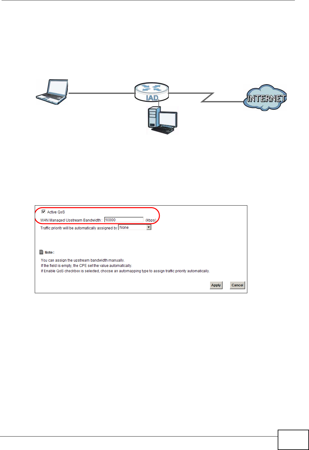
Chapter 3 Tutorials
P-2612HNU-Fx User’s Guide 77
Note: QoS is applied to traffic flowing out of the ZyXEL Device.
Traffic that does not match this class is assigned a priority queue based on the
internal QoS mapping table on the ZyXEL Device.
QoS Example
1Click Network Setting > QoS > General and check Active. Set your WAN
Managed Upstream Bandwidth to 10,000 kbps (or leave this blank to have the
ZyXEL Device automatically determine this figure). Click Apply to save your
settings.
Tutorial: Advanced > QoS
2Go to Network Setting > QoS > Queue Setup. Click Add new Queue to create
a new queue. In the screen that opens, check Active and enter or select the
following values, then click Apply.
•Name: Email
•Priority: 7 (High)
•Weight: 15
10,000 kbps
DSL
E-mail: Queue 7
Your computer
IP=192.168.1.23
A colleague’s computer
Other traffic: Automatic classifier
and/or
MAC=AA:FF:AA:FF:AA:FF
ZyXEL Device
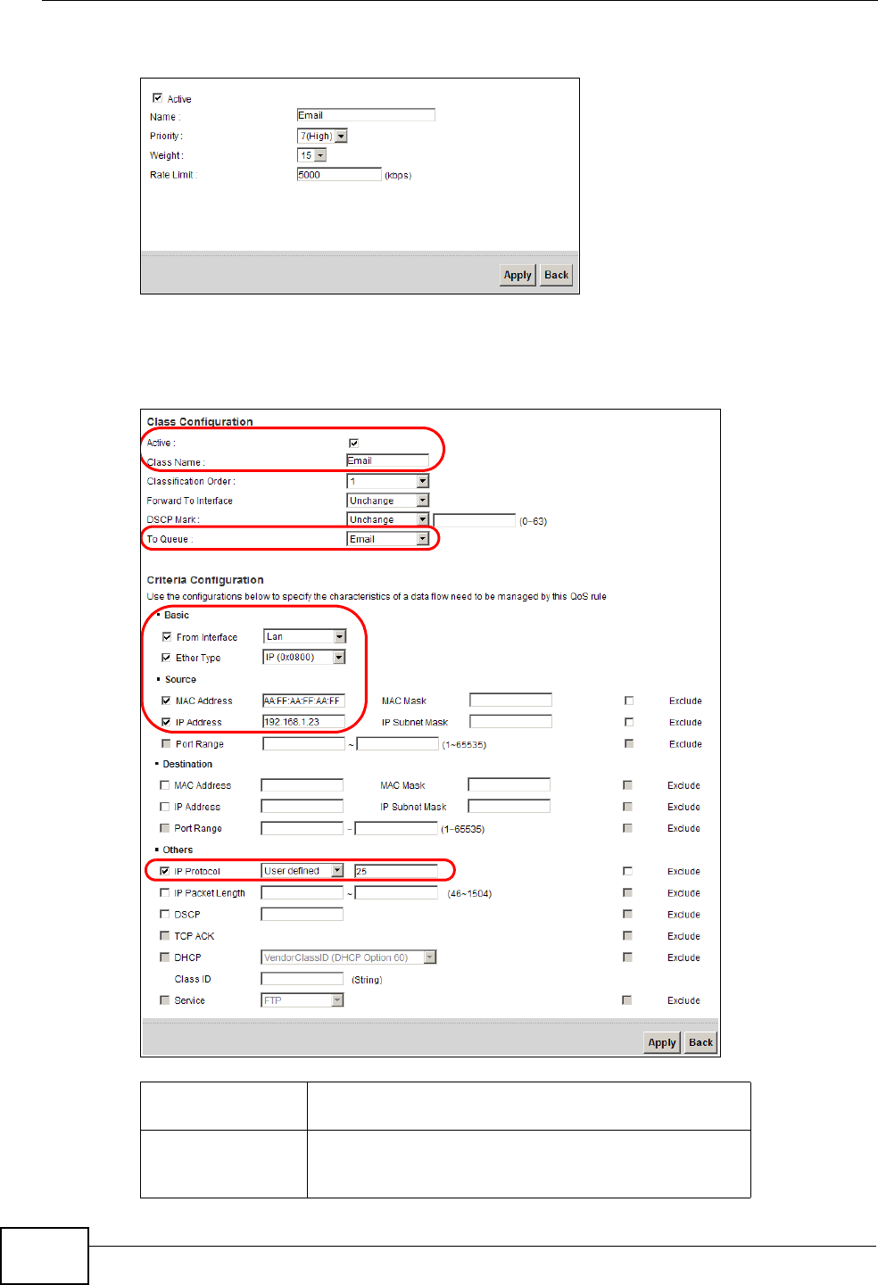
Chapter 3 Tutorials
P-2612HNU-Fx User’s Guide
78
•Rate Limit: 5,000 (kbps)
Tutorial: Advanced > QoS > Queue Setu p
3Go to Network Setting > QoS > Class Setup. Click Add new Classifier to
create a new class. Check Active and follow the settings as shown in the screen
below. Then click Apply.
Tutorial: Advanced > QoS > Class Set up
Class Name Give a class name to this traffic, such as Email in this
example.
To Queue Link this to a queue created in the QoS > Queue
Setup screen, which is the Email queue created in
this example.
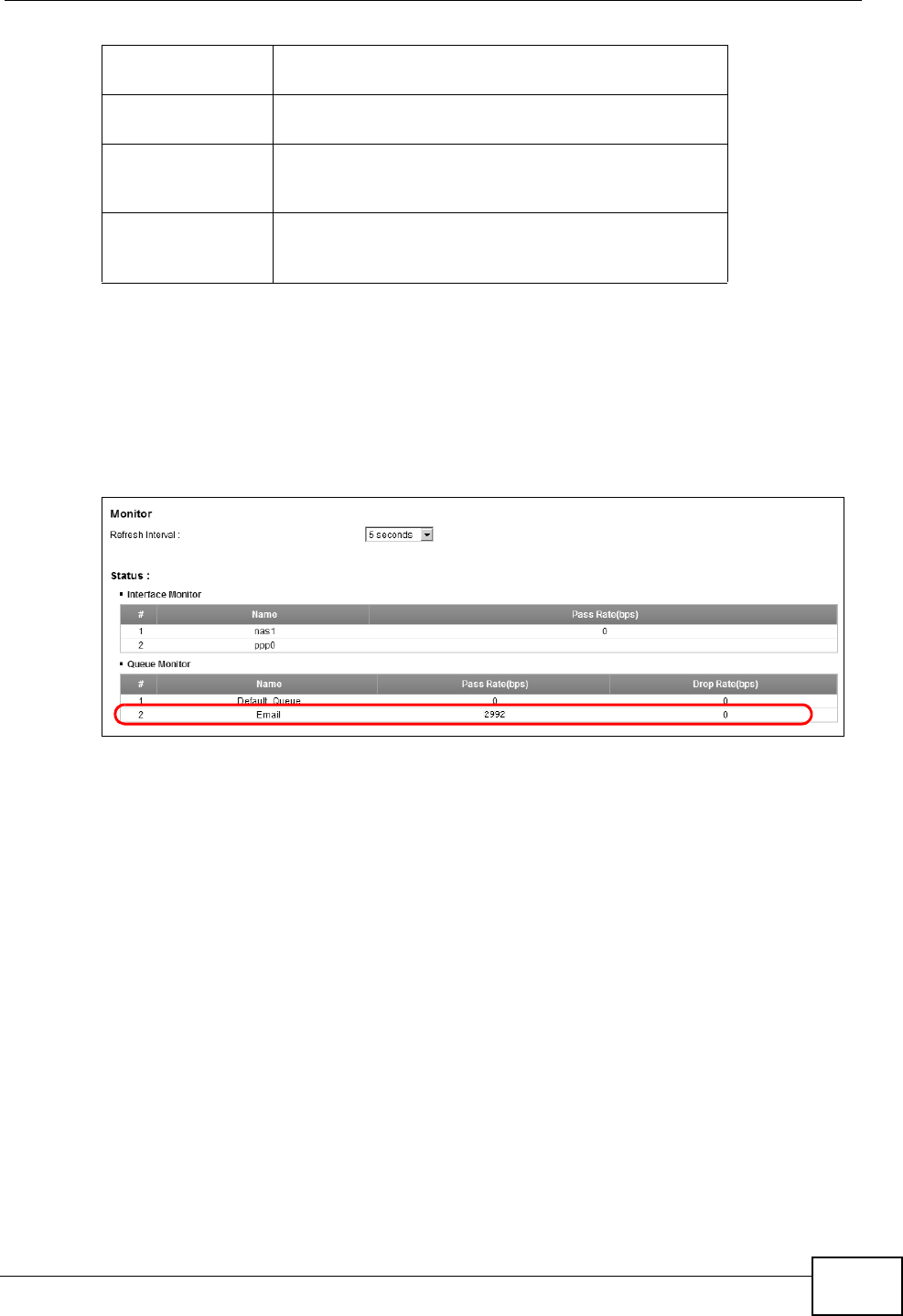
Chapter 3 Tutorials
P-2612HNU-Fx User’s Guide 79
This maps e-mail traffic to queue 7 created in the previous screen (see the IP
Protocol field). This also maps your computer’s IP address and MAC address to
queue 7 (see the Source fields).
4Verify that the queue setup works by checking Network Setting > QoS >
Monitor. This shows the bandwidth allotted to e-mail traffic compared to other
network traffic.
Tutorial: Advanced > QoS > Monitor
3.11 Access the ZyXEL Device Using DDNS
If you connect your ZyXEL Device to the Internet and it uses a dynamic WAN IP
address, it is inconvenient for you to manage the device from the Internet. The
From Interface This is the interface from which the traffic will be
coming from. Select Lan.
Ether Type Select IP to identify the traffic source by its IP
address or MAC address.
MAC Address Type the MAC address of your computer -
AA:FF:AA:FF:AA:FF. Type the MAC Mask if you
know it.
IP Address Type the IP address of your computer -
192.168.1.23. Type the IP Subnet Mask if you
know it.
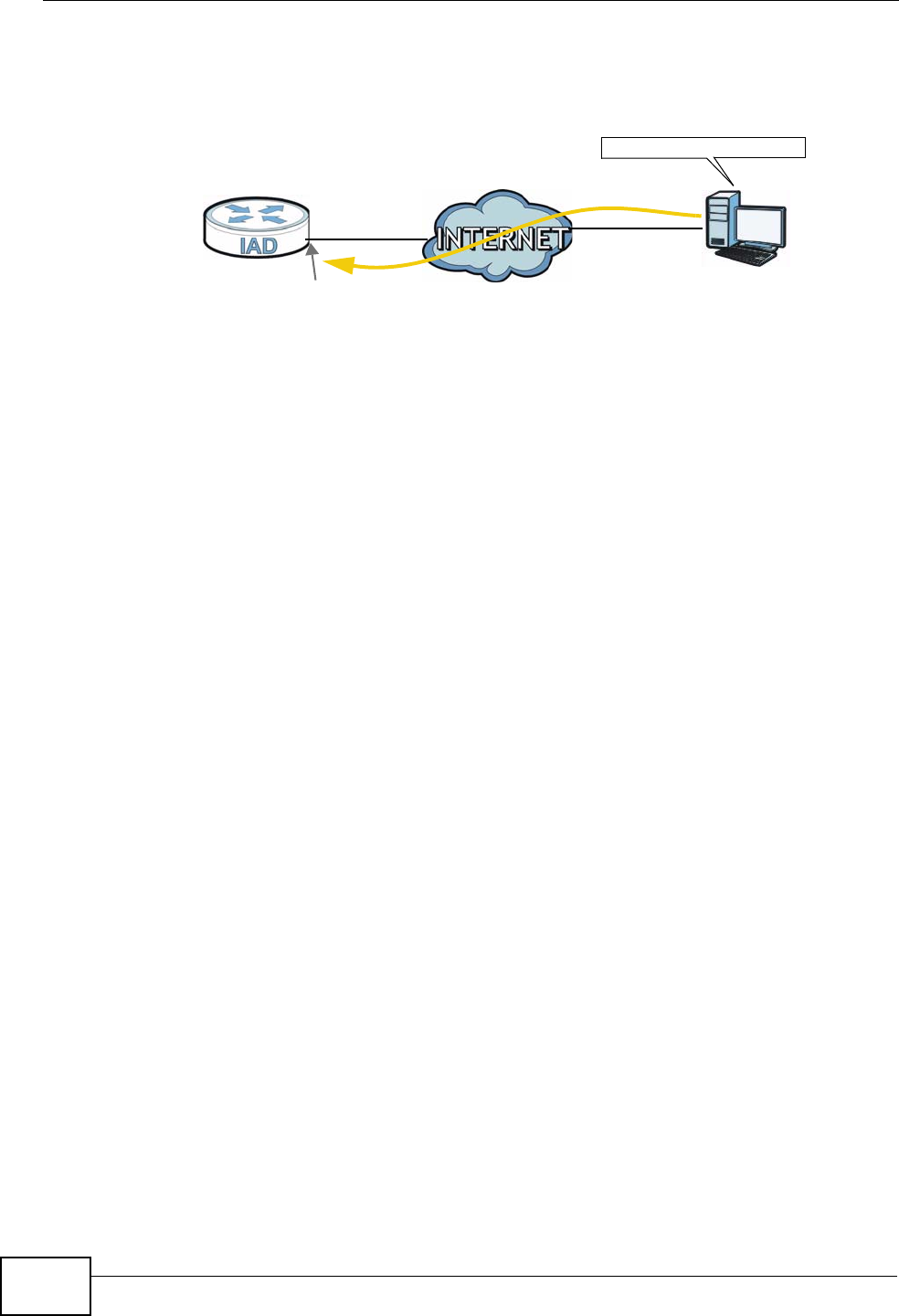
Chapter 3 Tutorials
P-2612HNU-Fx User’s Guide
80
ZyXEL Device’s WAN IP address changes dynamically. Dynamic DNS (DDNS)
allows you to access the ZyXEL Device using a domain name.
To use this feature, you have to apply for DDNS service at www.dyndns.org.
This tutorial shows you how to:
•Registering a DDNS Account on www.dyndns.org
•Configuring DDNS on Your ZyXEL Device
•Testing the DDNS Setting
Note: If you have a private WAN IP address, then you cannot use DDNS.
3.11.1 Registering a DDNS Account on www.dyndns.org
1Open a browser and type http://www.dyndns.org.
2Apply for a user account. This tutorial uses UserName1 and 12345 as the
username and password.
3Log into www.dyndns.org using your account.
4Add a new DDNS host name. This tutorial uses the following settings as an
example.
• Hostname: zyxelrouter.dyndns.org
• Service Type: Host with IP address
• IP Address: Enter the WAN IP address that your ZyXEL Device is currently using.
You can find the IP address on the ZyXEL Device’s web configurator Status
page.
Then you will need to configure the same account and host name on the ZyXEL
Device later.
w.x.y.z a.b.c.d
http://zyxelrouter.dyndns.org
A
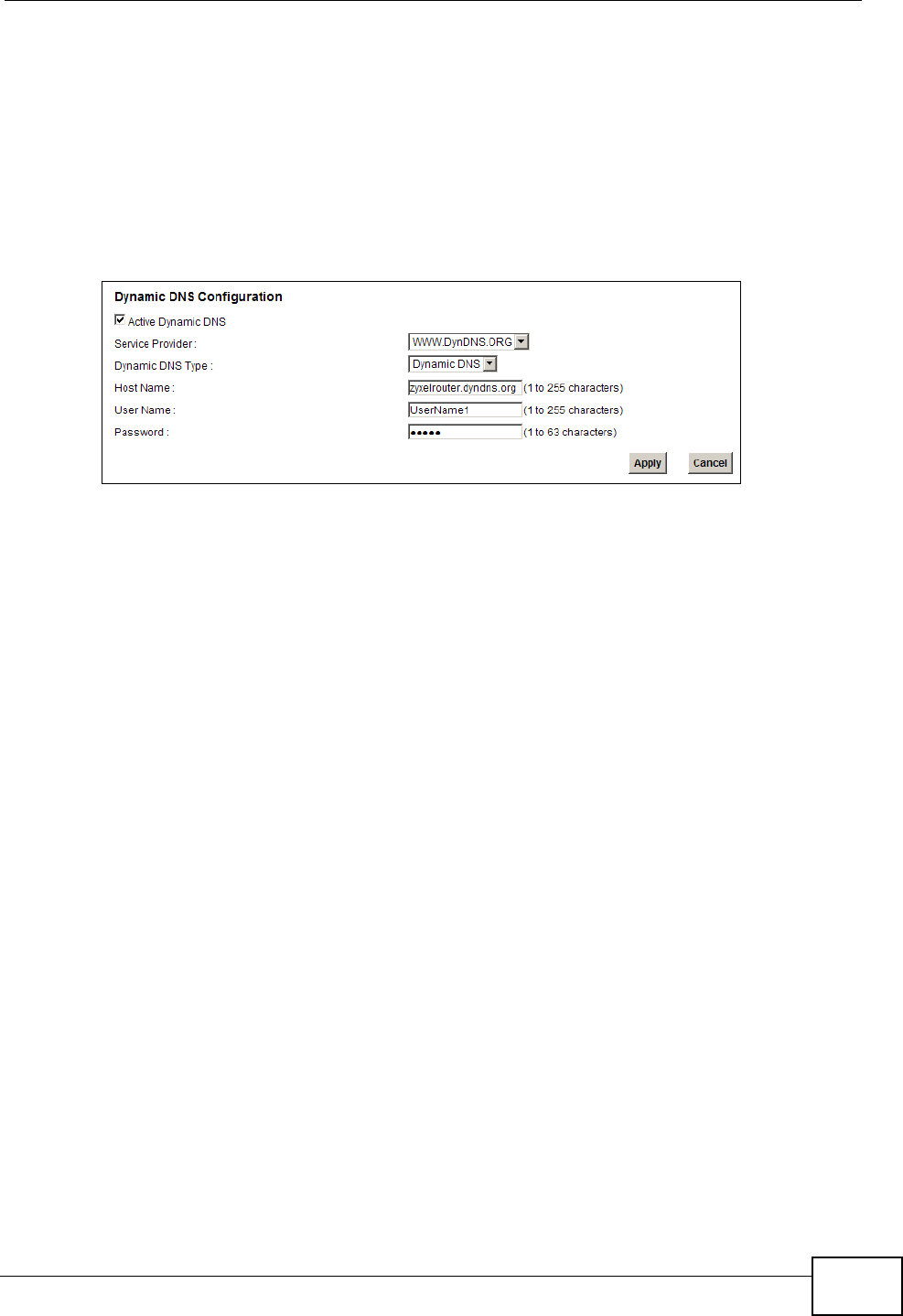
Chapter 3 Tutorials
P-2612HNU-Fx User’s Guide 81
3.11.2 Configuring DDNS on Your ZyXEL Device
Configure the following settings in the Network Setting > DNS screen.
• Select Active Dynamic DNS.
• Select Dynamic DNS for the DDNS type.
• Type zyxelrouter.dyndns.org in the Host Name field.
• Enter the user name (UserName1) and password (12345).
Click Apply.
3.11.3 Testing the DDNS Setting
Now you should be able to access the ZyXEL Device from the Internet. To test
this:
1Open a web browser on the computer (using the IP address a.b.c.d) that is
connected to the Internet.
2Type http://zyxelrouter.dyndns.org and press [Enter].
3The ZyXEL Device’s login page should appear. You can then log into the ZyXEL
Device and manage it.

Chapter 3 Tutorials
P-2612HNU-Fx User’s Guide
82

83
PART II
Technical Reference

84

P-2612HNU(L)-FxF User’s Guide 85
CHAPTER 4
Connection Status and System
Info Screens
4.1 Overview
After you log into the web configurator, the Connection Status screen appears.
This shows the network connection status of the ZyXEL Device and clients
connected to it.
Use the System Info screen to look at the current status of the device, system
resources, interfaces (LAN, WAN and WLAN), and SIP accounts. You can also
register and unregister SIP accounts.
4.2 The Connection Status Screen
Use this screen to view the network connection status of the device and its clients.
A warning message appears if there is a connection problem.
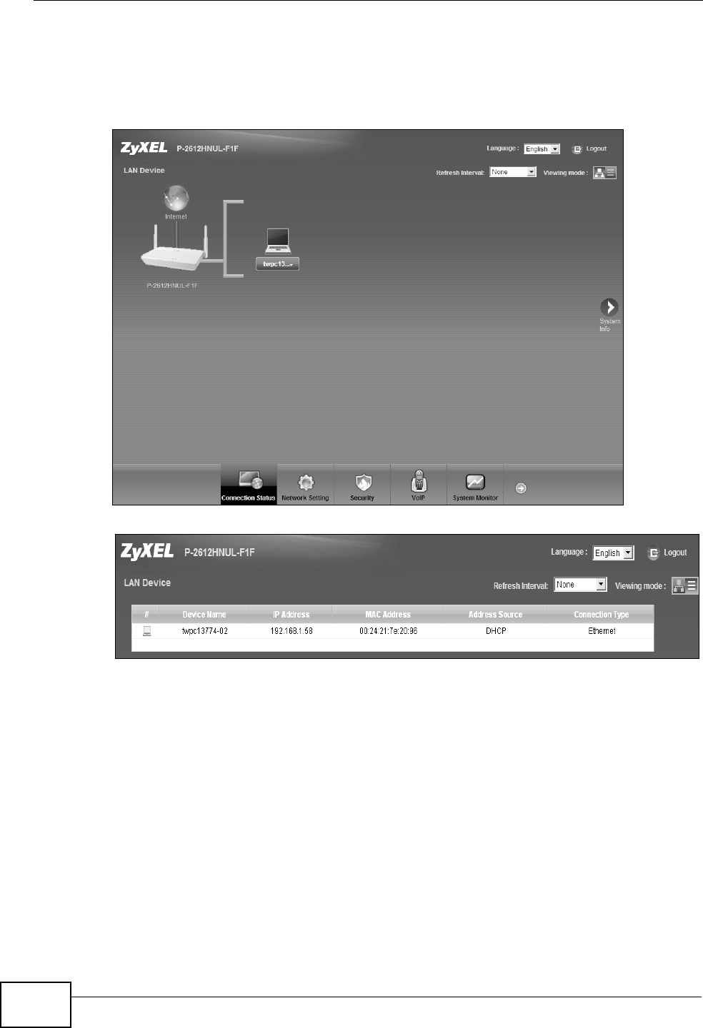
Chapter 4 Connection Status and System Info Screens
P-2612HNU(L)-FxF User’s Guide
86
If you prefer to view the status in a list, click List View in the Viewing mode
selection box. You can configure how often you want the ZyXEL Device to update
this screen in Refresh Interval.
Figure 11 Connection Status: Icon View
Figure 12 Connection Status: List View
In Icon View, if you want to view information about a client, click the client’s
name and Info. Click the IP address if you want to change it. If you want to
change the name or icon of the client, click Change name/icon.
In List View, you can also view the client’s information.
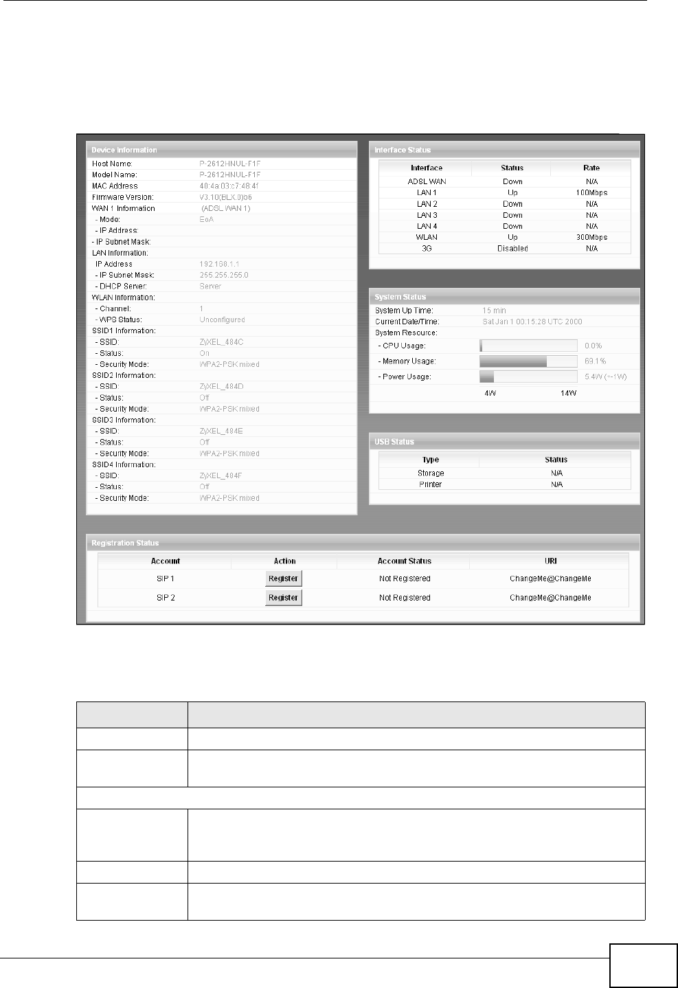
Chapter 4 Connection Status and System Info Screens
P-2612HNU(L)-FxF User’s Guide 87
4.3 The System Info Screen
Click Connection Status > System Info to open this screen.
Figure 13 System Info Screen
Each field is described in the following table.
Table 4 System Info Screen
LABEL DESCRIPTION
Language Select the web configurator language from the drop-down list box.
Refresh Interval Select how often you want the ZyXEL Device to update this screen from
the drop-down list box.
Device Information
Host Name This field displays the ZyXEL Device system name. It is used for
identification. You can change this in the Maintenance > System
screen’s Host Name field.
Model Name This is the model name of your device.
MAC
Address This is the MAC (Media Access Control) or Ethernet address unique to
your ZyXEL Device.
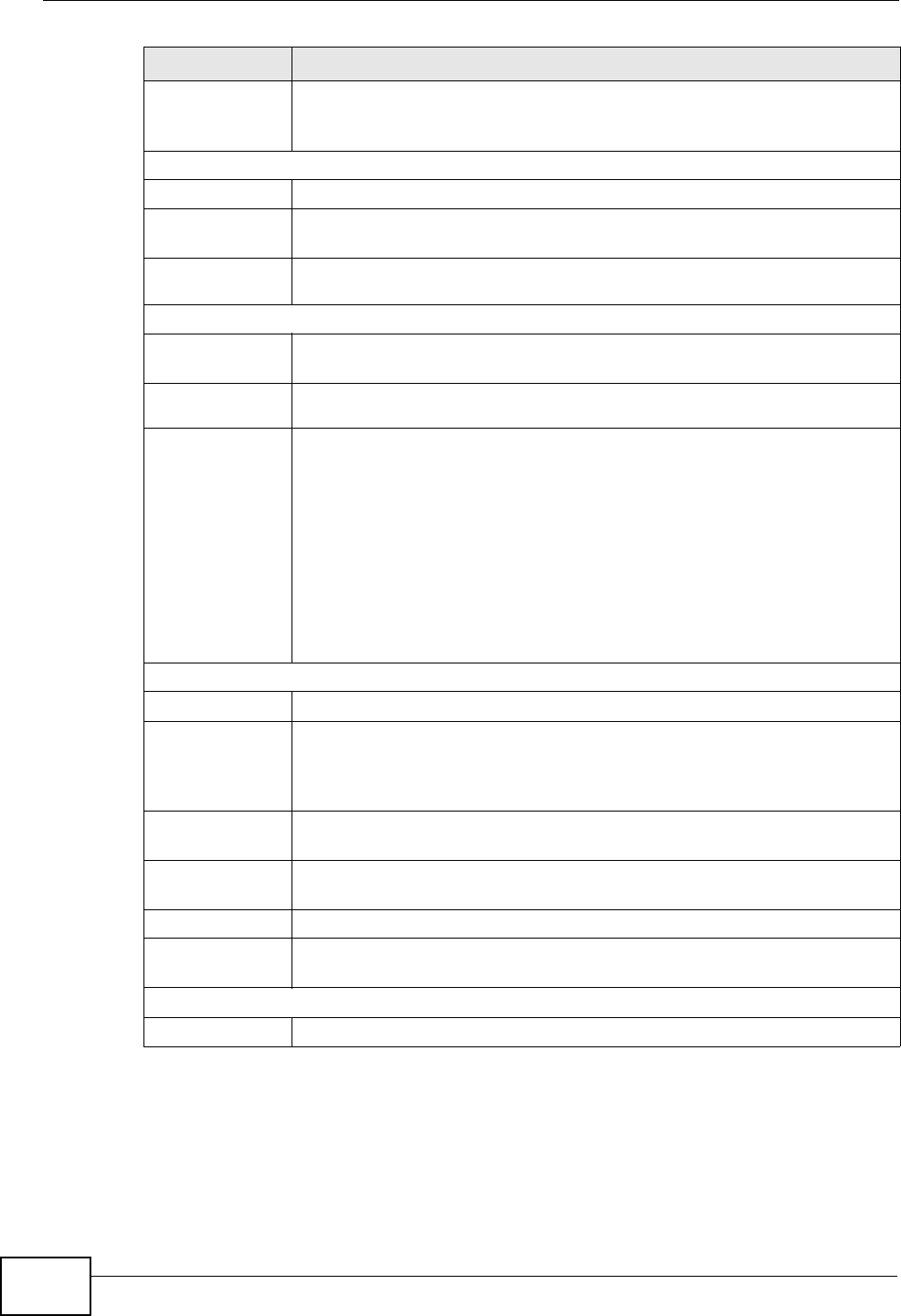
Chapter 4 Connection Status and System Info Screens
P-2612HNU(L)-FxF User’s Guide
88
Firmware
Version This field displays the current version of the firmware inside the device.
It also shows the date the firmware version was created. Go to the
Maintenance > Firmware Upgrade screen to change it.
WAN Information
Mode This is the method of encapsulation used by your ISP.
IP Address This field displays the current IP address of the ZyXEL Device in the
WAN.
IP Subnet
Mask This field displays the current subnet mask in the WAN.
LAN Information
IP Address This field displays the current IP address of the ZyXEL Device in the
LAN.
IP Subnet
Mask This field displays the current subnet mask in the LAN.
DHCP Server This field displays what DHCP services the ZyXEL Device is providing to
the LAN. Choices are:
Server - The ZyXEL Device is a DHCP server in the LAN. It assigns IP
addresses to other computers in the LAN.
Relay - The ZyXEL Device acts as a surrogate DHCP server and relays
DHCP requests and responses between the remote server and the
clients.
None - The ZyXEL Device is not providing any DHCP services to the
LAN.
WLAN Information
Channel This is the channel number used by the ZyXEL Device now.
WPS Status Configured displays when a wireless client has connected to the ZyXEL
Device or WPS is enabled and wireless or wireless security settings have
been configured. Unconfigured displays if WPS is disabled or wireless
security settings have not been configured.
SSID (1~4)
Information
SSID This is the descriptive name used to identify the ZyXEL Device in the
wireless LAN.
Status This shows whether or not the SSID is enabled (on).
Security
Mode This displays the type of security the ZyXEL Device is using in the
wireless LAN.
Interface Status
Interface This column displays each interface the ZyXEL Device has.
LABEL DESCRIPTION
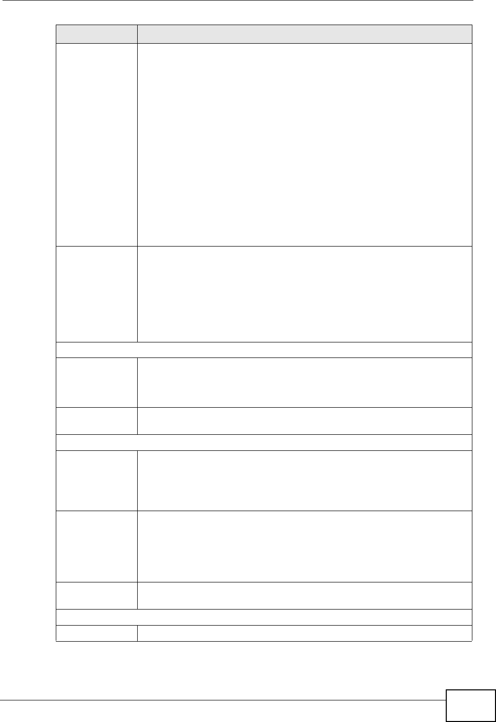
Chapter 4 Connection Status and System Info Screens
P-2612HNU(L)-FxF User’s Guide 89
Status This field indicates whether or not the ZyXEL Device is using the
interface.
For the DSL interface, this field displays Down (line is down), Up (line
is up or connected) if you're using Ethernet encapsulation and Down
(line is down), Up (line is up or connected), Idle (line (ppp) idle), Dial
(starting to trigger a call) and Drop (dropping a call) if you're using
PPPoE encapsulation.
For the WAN interface, this field displays Up when the ZyXEL Device is
using the interface and Down when the ZyXEL Device is not using the
interface.
For the LAN interface, this field displays Up when the ZyXEL Device is
using the interface and Down when the ZyXEL Device is not using the
interface.
For the WLAN interface, it displays Active when WLAN is enabled or
InActive when WLAN is disabled.
Rate For the LAN interface, this displays the port speed and duplex setting.
For the WAN interface, this displays the port speed and duplex setting.
For the DSL interface, it displays the downstream and upstream
transmission rate.
For the WLAN interface, it displays the maximum transmission rate
when WLAN is enabled or N/A when WLAN is disabled.
System Status
System Up
Time This field displays how long the ZyXEL Device has been running since it
last started up. The ZyXEL Device starts up when you plug it in, when
you restart it (Maintenance > Reboot), or when you reset it (see
Chapter 1 on page 28).
Current
Date/Time This field displays the current date and time in the ZyXEL Device. You
can change this in Maintenance > Time Setting.
System Resource
CPU Usage This field displays what percentage of the ZyXEL Device’s processing
ability is currently used. When this percentage is close to 100%, the
ZyXEL Device is running at full load, and the throughput is not going to
improve anymore. If you want some applications to have more
throughput, you should turn off other applications.
Memory
Usage This field displays what percentage of the ZyXEL Device’s memory is
currently used. Usually, this percentage should not increase much. If
memory usage does get close to 100%, the ZyXEL Device is probably
becoming unstable, and you should restart the device. See Chapter 25
on page 281, or turn off the device (unplug the power) for a few
seconds.
Power Usage This field displays what percentage of traffic passing through the ZyXEL
Device is using NAT.
USB Status
Type This shows the type of device connected to the ZyXEL Device.
LABEL DESCRIPTION
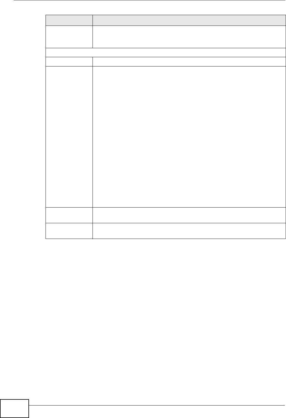
Chapter 4 Connection Status and System Info Screens
P-2612HNU(L)-FxF User’s Guide
90
Status This shows whether the device is currently active (Up). This shows N/A
if there are no device connected to the ZyXEL Device or the connected
device is not working.
Registration Status
Account This column displays each SIP account in the ZyXEL Device.
Action This field displays the current registration status of the SIP account. You
have to register SIP accounts with a SIP server to use VoIP.
If the SIP account is already registered with the SIP server,
• Click Unregister to delete the SIP account’s registration in the SIP
server. This does not cancel your SIP account, but it deletes the
mapping between your SIP identity and your IP address or domain
name.
• The second field displays Registered.
If the SIP account is not registered with the SIP server,
• Click Register to have the ZyXEL Device attempt to register the SIP
account with the SIP server.
• The second field displays the reason the account is not registered.
Inactive - The SIP account is not active. You can activate it in VoIP >
SIP > SIP Settings.
Register Fail - The last time the ZyXEL Device tried to register the SIP
account with the SIP server, the attempt failed. The ZyXEL Device
automatically tries to register the SIP account when you turn on the
ZyXEL Device or when you activate it.
Account
Status This shows Active when the SIP account has been registered and ready
for use or In-Active when the SIP account is not yet registered.
URI This field displays the account number and service domain of the SIP
account. You can change these in VoIP > SIP > SIP Settings.
LABEL DESCRIPTION
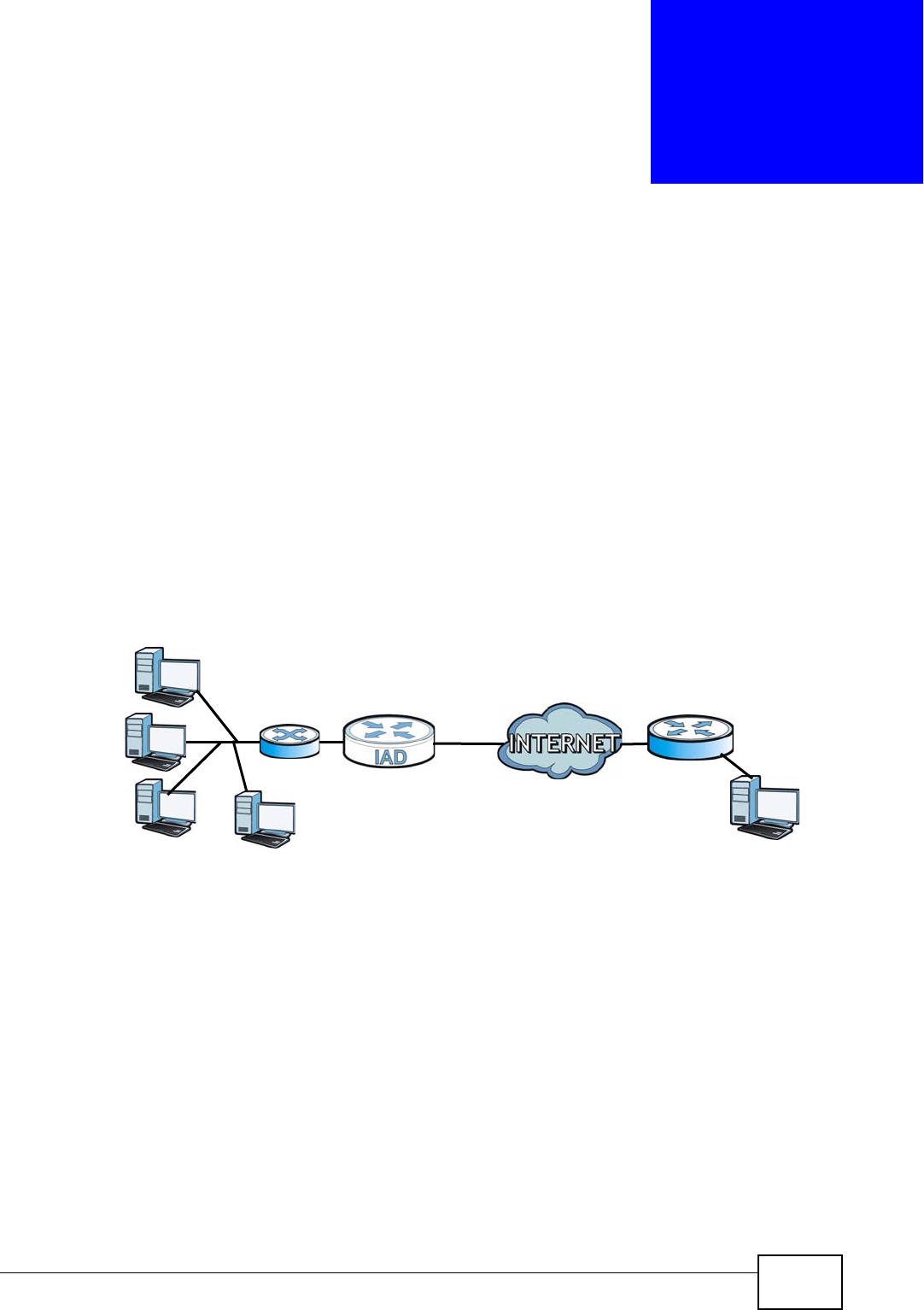
P-2612HNU(L)-FxF User’s Guide 91
CHAPTER 5
Broadband
5.1 Overview
This chapter discusses the ZyXEL Device’s Broadband screens. Use these screens
to configure your ZyXEL Device for Internet access.
A WAN (Wide Area Network) connection is an outside connection to another
network or the Internet. It connects your private networks, such as a LAN (Local
Area Network) and other networks, so that a computer in one location can
communicate with computers in other locations.
Figure 14 LAN and WAN
3G (third generation) standards for the sending and receiving of voice, video, and
data in a mobile environment.
WAN
LAN
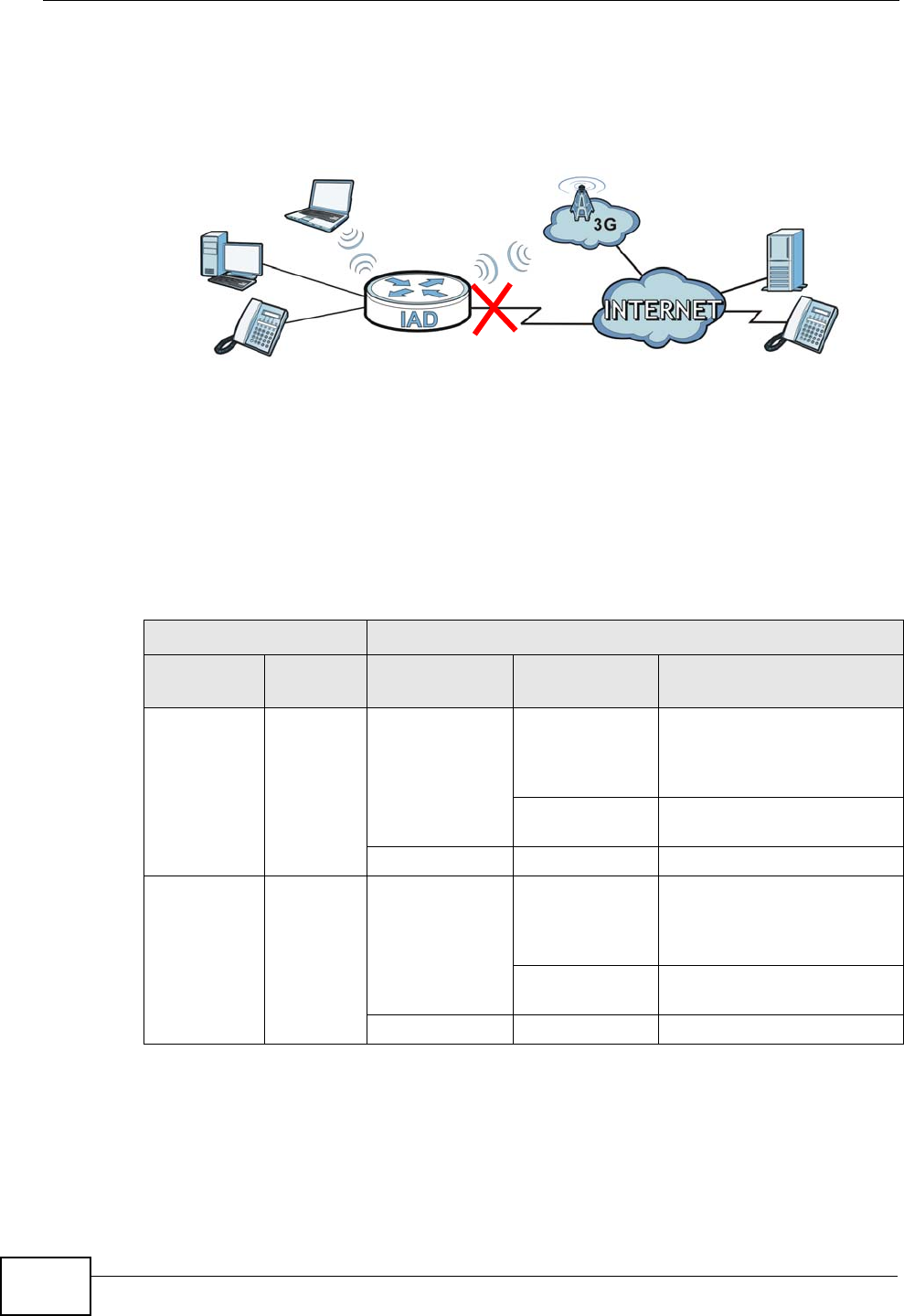
Chapter 5 Broadband
P-2612HNU(L)-FxF User’s Guide
92
You can attach a 3G wireless adapter to the USB port and set the ZyXEL Device to
use this 3G connection as your WAN or a backup when the wired WAN connection
fails.
Figure 15 3G WAN Connection
5.1.1 What You Can Do in this Chapter
• Use the Broadband screen to view, remove or add a WAN interface. You can
also configure the WAN settings on the ZyXEL Device for Internet access
(Section 5.2 on page 94).
• Use the 3G Backup screen to configure 3G WAN connection (Section 5.3 on
page 108).
5.1.2 What You Need to Know
The following terms and concepts may help as you read this chapter.
Table 5 WAN Setup Overview
LAYER-2 INTERFACE INTERNET CONNECTION
INTERFACE DSL LINK
TYPE MODE WAN SERVICE
TYPE CONNECTION SETTINGS
Ethernet Routing PPPoE PPP user name and
password, WAN IP address,
DNS server and default
gateway
IPoE WAN IP address, NAT, DNS
server and default gateway
Bridge N/A N/A
ATM EoA Routing PPPoE PPP user name and
password, WAN IP address,
DNS server and default
gateway
IPoE WAN IP address, NAT, DNS
server and default gateway
Bridge N/A N/A

Chapter 5 Broadband
P-2612HNU(L)-FxF User’s Guide 93
Encapsulation Method
Encapsulation is used to include data from an upper layer protocol into a lower
layer protocol. To set up a WAN connection to the Internet, you need to use the
same encapsulation method used by your ISP (Internet Service Provider). If your
ISP offers a dial-up Internet connection using PPPoE (PPP over Ethernet), they
should also provide a username and password (and service name) for user
authentication.
WAN IP Address
The WAN IP address is an IP address for the ZyXEL Device, which makes it
accessible from an outside network. It is used by the ZyXEL Device to
communicate with other devices in other networks. It can be static (fixed) or
dynamically assigned by the ISP each time the ZyXEL Device tries to access the
Internet.
If your ISP assigns you a static WAN IP address, they should also assign you the
subnet mask and DNS server IP address(es).
ATM
Asynchronous Transfer Mode (ATM) is a LAN and WAN networking technology that
provides high-speed data transfer. ATM uses fixed-size packets of information
called cells. With ATM, a high QoS (Quality of Service) can be guaranteed. ATM
uses a connection-oriented model and establishes a virtual circuit (VC) between
two endpoints before the actual data exchange begins.
3G
3G (Third Generation) is a digital, packet-switched wireless technology. Bandwidth
usage is optimized as multiple users share the same channel and bandwidth is
only allocated to users when they send data. It allows fast transfer of voice and
non-voice data and provides broadband Internet access to mobile devices.
Finding Out More
• See Section 5.4 on page 110 for advanced technical information on WAN and
3G.
• See Chapter 3 on page 37 for WAN tutorials.
5.1.3 Before You Begin
You need to know your Internet access settings such as encapsulation and WAN IP
address. Get this information from your ISP.
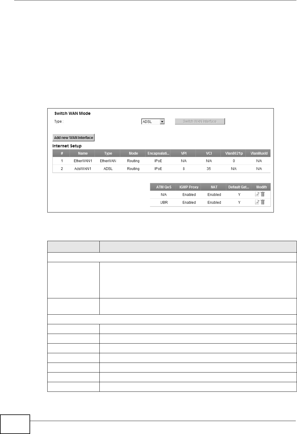
Chapter 5 Broadband
P-2612HNU(L)-FxF User’s Guide
94
5.2 The Broadband Screen
The ZyXEL Device must have a WAN interface to allow users to use the Ethernet
WAN port or DSL port to access the Internet. Use the Broadband screen to view,
remove or add a WAN interface.
Note: The ATM and Ethernet layer-2 interfaces cannot work at the same time.
Click Network Setting > Broadband. The following screen opens.
Figure 16 Network Setting > Broadband
The following table describes the fields in this screen.
Table 6 Network Setting > Broadband
LABEL DESCRIPTION
Switch WAN Mode
Type The default WAN mode is ADSL. If you prefer not to use a DSL line
and you have another broadband modem or router (such as ADSL)
available, you can select EtherWAN from the drop-down list box and
click Switch WAN Interface. The ZyXEL Device will use Ethernet
WAN as the WAN mode.
Add new WAN
Interface
Click this to create a new WAN interface.
Internet Setup
# This is the index number of the connection.
Name This is the service name of the connection.
Type This shows the type of interface used by this connection.
Mode This shows whether the connection is in routing mode or bridge mode.
Encapsulation This shows the method of encapsulation used by this connection.
VPI This is the Virtual Path Identifier (VPI).
VCI This is the Virtual Channel Identifier (VCI).
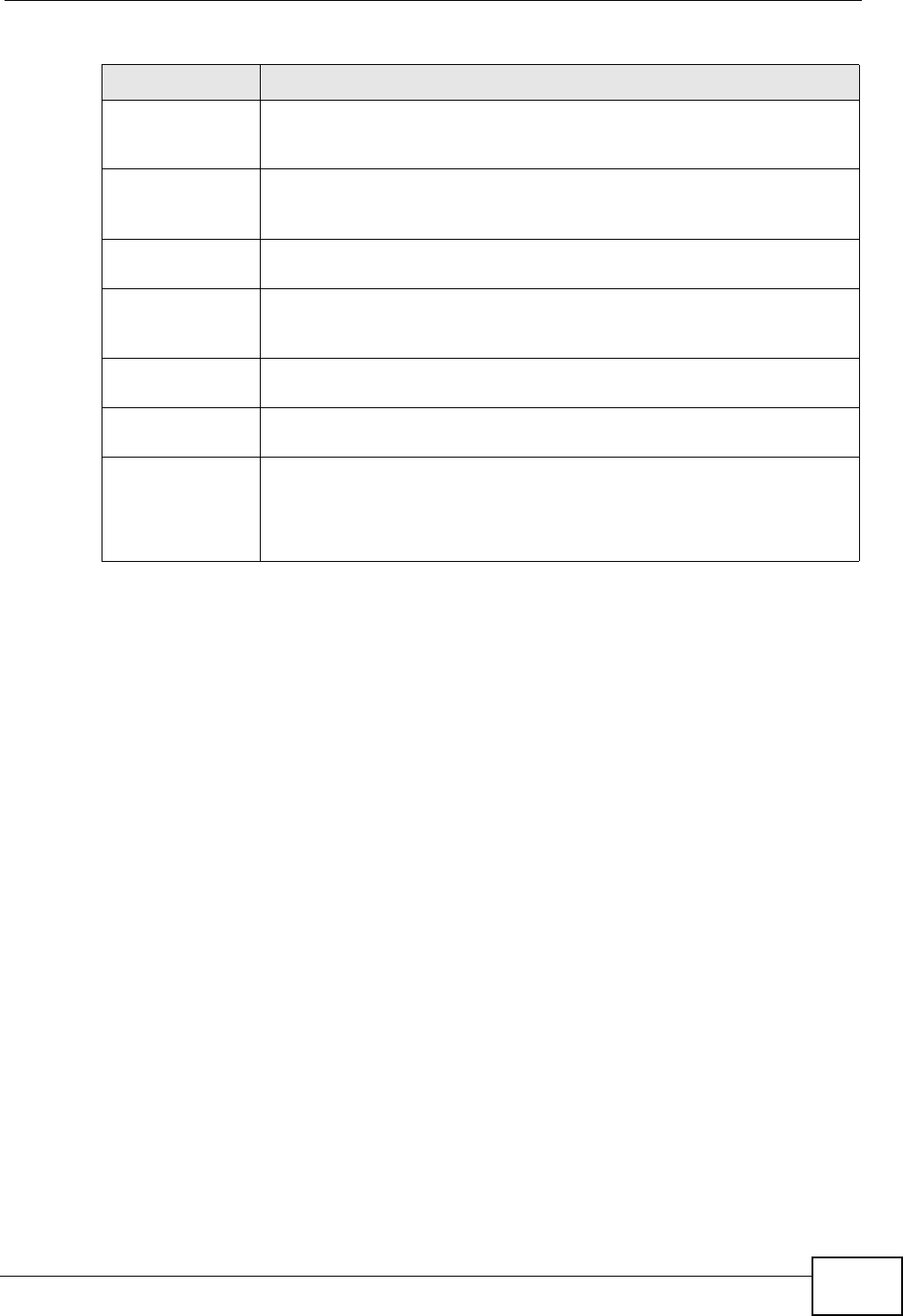
Chapter 5 Broadband
P-2612HNU(L)-FxF User’s Guide 95
5.2.1 Add/Edit Internet Connection
Use this screen to configure a WAN connection. The screen varies depending on
the encapsulation and WAN service type you select.
Vlan8021p This indicates the 802.1P priority level assigned to traffic sent through
this connection. This displays N/A when there is no priority level
assigned.
VlanMuxId This indicates the VLAN ID number assigned to traffic sent through
this connection. This displays N/A when there is no VLAN ID number
assigned.
ATM QoS This shows the ATM Quality of Service (QoS) type configured for this
connection. This displays N/A when there is no ATM QoS assigned.
IGMP Proxy This shows whether IGMP (Internet Group Multicast Protocol) is
activated or not for this connection. IGMP is not available when the
connection uses the bridging service.
NAT This shows whether NAT is activated or not for this connection. NAT is
not available when the connection uses the bridging service.
Default Gateway This shows whether the ZyXEL Device uses the interface of this
connection as the system default gateway.
Modify Click the Edit icon to configure the connection.
Click the Delete icon to delete this connection from the ZyXEL Device.
A window displays asking you to confirm that you want to delete the
connection.
Table 6 Network Setting > Broadband (continued)
LABEL DESCRIPTION
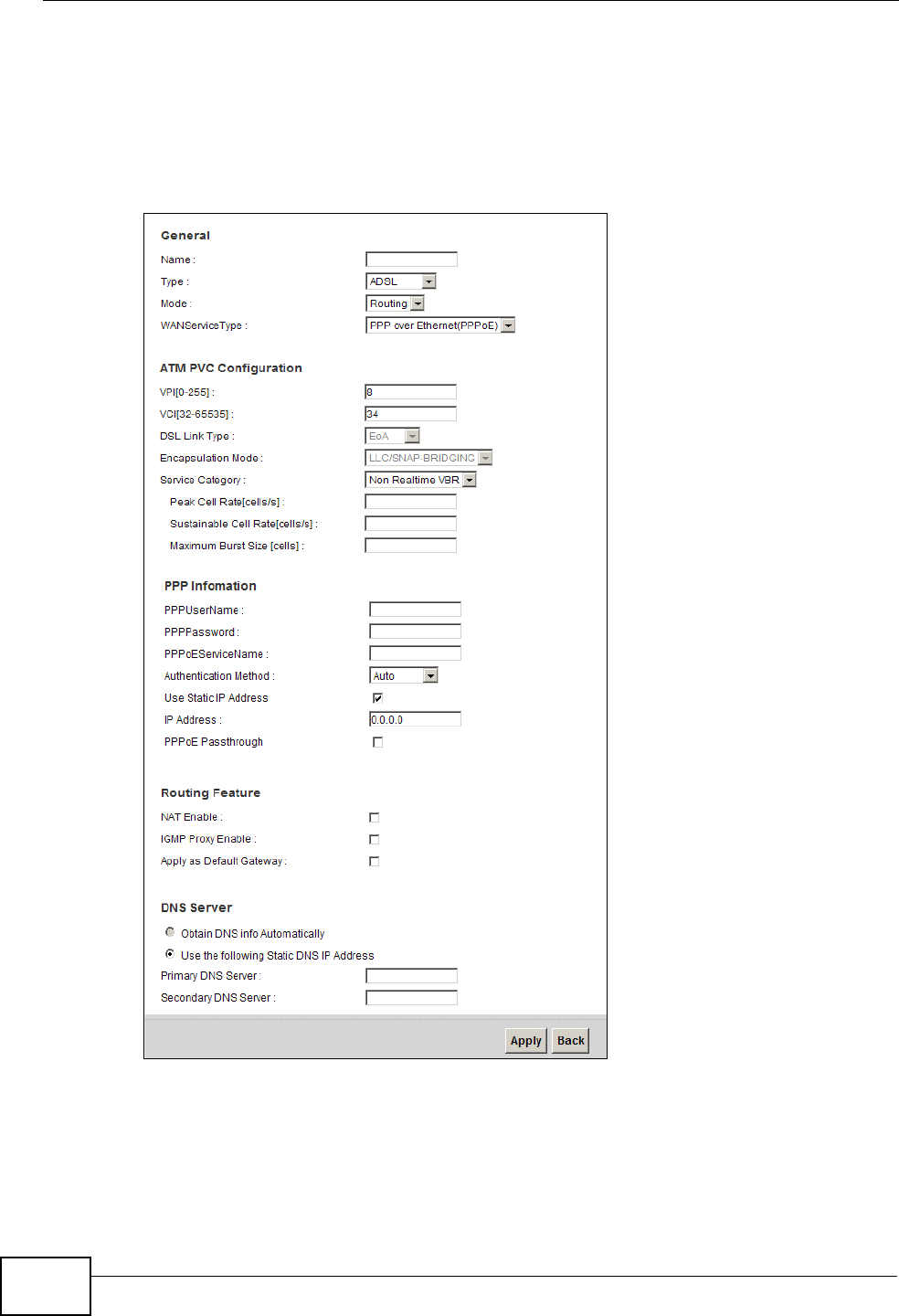
Chapter 5 Broadband
P-2612HNU(L)-FxF User’s Guide
96
5.2.1.1 Routing- PPPoE
Click the Add new WAN Interface in the Network Setting > Broadband
screen or the Edit icon next to the connection you want to configure. Select
Routing as the encapsulation mode and PPPoE as the WAN service type.
Figure 17 Broadband Add/Edit: Routing- PPPoE
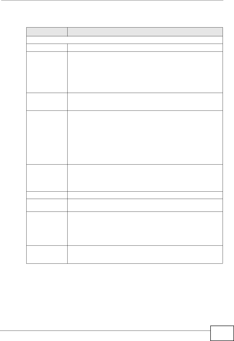
Chapter 5 Broadband
P-2612HNU(L)-FxF User’s Guide 97
The following table describes the fields in this screen.
Table 7 Broadband Add/Edit: Routing- PPPoE
Label DESCRIPTION
General
Name Enter a service name of the connection.
Type Select an interface for which you want to configure here.
ADSL: The ZyXEL Device uses the ADSL technology for data
transmission over the DSL port.
EtherWAN: The ZyXEL Device transmits data over the Ethernet WAN
port. Select this if you have a DSL router or modem in your network
already.
Mode Select Routing (default) from the drop-down list box if your ISP give
you one IP address only and you want multiple computers to share an
Internet account.
WAN Service
Type
This field is available only when you select Routing in the Mode field.
Select the method of encapsulation used by your ISP.
•PPP over Ethernet (PPPoE) - PPPoE (Point to Point Protocol over
Ethernet) provides access control and billing functionality in a
manner similar to dial-up services using PPP. Select this if you have
a username and password for Internet access.
•IP over Ethernet - In this type of Internet connection, IP packets
are routed between the Ethernet interface and the WAN interface
and then formatted so that they can be understood in a bridged
environment.
ATM PVC
Configuration
VPI (Virtual Path Identifier) and VCI (Virtual Channel Identifier) define
a virtual circuit.
This section is available only when you select ADSL in the Type field
to configure an ATM layer-2 interface.
VPI The valid range for the VPI is 0 to 255. Enter the VPI assigned to you.
VCI The valid range for the VCI is 32 to 65535 (0 to 31 is reserved for local
management of ATM traffic). Enter the VCI assigned to you.
DSL Link Type The DSL link type is set to EoA (Ethernet over ATM) to have an
Ethernet header in the packet, so that you can have multiple services/
connections over one PVC. You can set each connection to have its
own MAC address or all connections share one MAC address but use
different VLAN IDs for different services. EoA supports IPoE, PPPoE
and RFC1483/2684 bridging encapsulation methods.
Encapsulation
Mode
The encapsulation method of multiplexing used by your is LLC/SNAP-
BRIDGING. In LCC encapsulation, bridged PDUs are encapsulated by
identifying the type of the bridged media in the SNAP header.
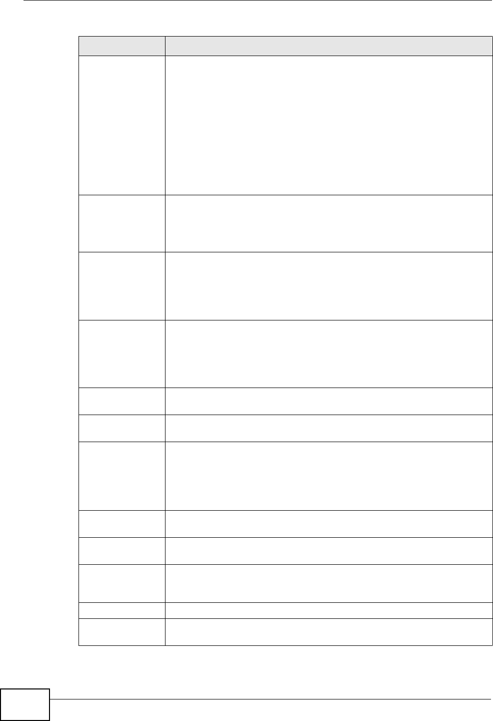
Chapter 5 Broadband
P-2612HNU(L)-FxF User’s Guide
98
Service Category Select UBR Without PCR for applications that are non-time sensitive,
such as e-mail.
Select CBR (Constant Bit Rate) to specify fixed (always-on) bandwidth
for voice or data traffic.
Select Non Realtime VBR (non real-time Variable Bit Rate) for
connections that do not require closely controlled delay and delay
variation.
Select Realtime VBR (real-time Variable Bit Rate) for applications
with bursty connections that require closely controlled delay and delay
variation.
Peak Cell Rate Divide the DSL line rate (bps) by 424 (the size of an ATM cell) to find
the Peak Cell Rate (PCR). This is the maximum rate at which the
sender can send cells. Type the PCR here.
This field is not available when you select UBR Without PCR.
Sustainable
Cell Rate The Sustain Cell Rate (SCR) sets the average cell rate (long-term) that
can be transmitted. Type the SCR, which must be less than the PCR.
Note that system default is 0 cells/sec.
This field is available only when you select Non Realtime VBR or
Realtime VBR.
Maximum
Burst Size Maximum Burst Size (MBS) refers to the maximum number of cells
that can be sent at the peak rate. Type the MBS, which is less than
65535.
This field is available only when you select Non Realtime VBR or
Realtime VBR.
VLAN This section is available only when you select EtherWAN in the Type
field.
Enable VLAN Select this to add the VLAN tag (specified below) to the outgoing
traffic through this connection.
Enter 802.1P
Priority
IEEE 802.1p defines up to 8 separate traffic types by inserting a tag
into a MAC-layer frame that contains bits to define class of service.
Type the IEEE 802.1p priority level (from 0 to 7) to add to traffic
through this connection. The greater the number, the higher the
priority level.
Enter 802.1Q
VLAN ID
Type the VLAN ID number (from 1 to 4094) for traffic through this
connection.
PPP Information This section is available only when you select Routing in the Mode
field and PPPoE in the WAN Service Type field.
PPP User Name Enter the user name exactly as your ISP assigned. If assigned a name
in the form user@domain where domain identifies a service name,
then enter both components exactly as given.
PPP Password Enter the password associated with the user name above.
PPPoE Service
Name
Type the name of your PPPoE service here.
Table 7 Broadband Add/Edit: Routing- PPPoE (continued)
Label DESCRIPTION
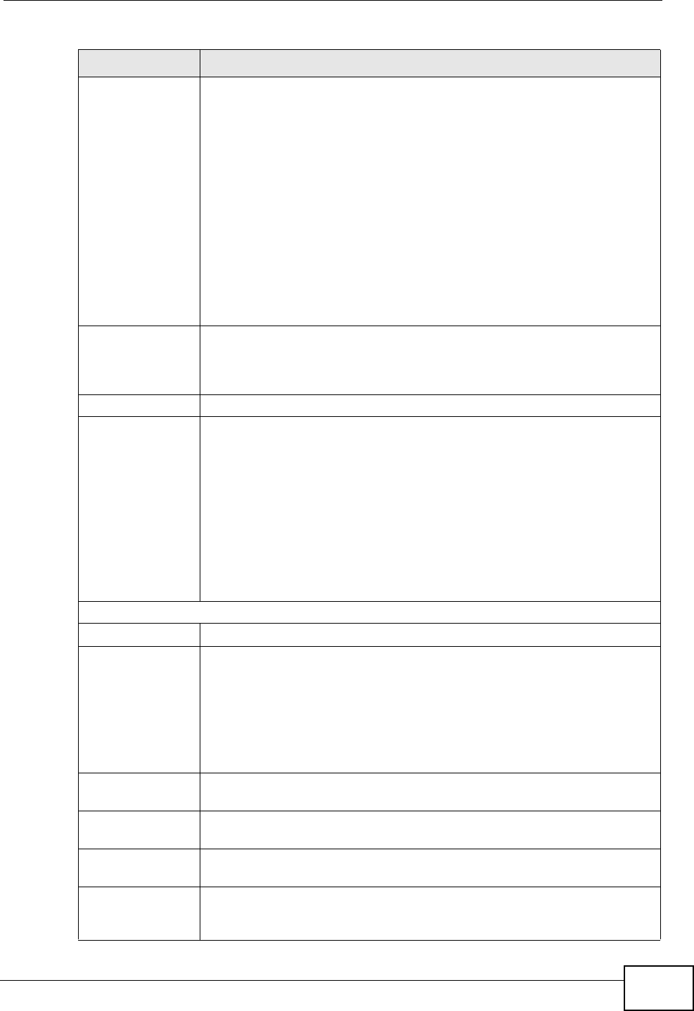
Chapter 5 Broadband
P-2612HNU(L)-FxF User’s Guide 99
Authentication
Mode
The ZyXEL Device supports PAP (Password Authentication Protocol)
and CHAP (Challenge Handshake Authentication Protocol). CHAP is
more secure than PAP; however, PAP is readily available on more
platforms.
Use the drop-down list box to select an authentication protocol for
outgoing calls. Options are:
AUTO: Your ZyXEL Device accepts either CHAP or PAP when requested
by this remote node.
CHAP: Your ZyXEL Device accepts CHAP only.
PAP: Your ZyXEL Device accepts PAP only.
MSCHAP: Your ZyXEL Device accepts MSCHAP only. MS-CHAP is the
Microsoft version of the CHAP.
Use Static IP
Address
A static IP address is a fixed IP that your ISP gives you. A dynamic IP
address is not fixed; the ISP assigns you a different one each time you
connect to the Internet. Select this if you want to get a dynamic IP
address from the ISP.
IP Address Enter the static IP address provided by your ISP.
PPPoE
Passthrough
In addition to the ZyXEL Device’s built-in PPPoE client, you can enable
PPPoE pass through to allow up to ten hosts on the LAN to use PPPoE
client software on their computers to connect to the ISP via the ZyXEL
Device. Each host can have a separate account and a public WAN IP
address.
PPPoE pass through is an alternative to NAT for application where NAT
is not appropriate.
Disable PPPoE pass through if you do not need to allow hosts on the
LAN to use PPPoE client software on their computers to connect to the
ISP.
Routing Feature
NAT Enable Select this option to activate NAT on this connection.
IGMP Proxy
Enable
Internet Group Multicast Protocol (IGMP) is a network-layer protocol
used to establish membership in a Multicast group - it is not used to
carry user data.
Select this option to have the ZyXEL Device act as an IGMP proxy on
this connection. This allows the ZyXEL Device to get subscribing
information and maintain a joined member list for each multicast
group. It can reduce multicast traffic significantly.
Apply as Default
Gateway
Select this option to have the ZyXEL Device use the WAN interface of
this connection as the system default gateway.
DNS Server The section is not available when you select Bridge in the WAN
Service Type field.
Obtain DNS info
Automatically
Select this to have the ZyXEL Device get the DNS server addresses
from the ISP automatically.
Use the following
Static DNS IP
Address
Select this to have the ZyXEL Device use the DNS server addresses
you configure manually.
Table 7 Broadband Add/Edit: Routing- PPPoE (continued)
Label DESCRIPTION
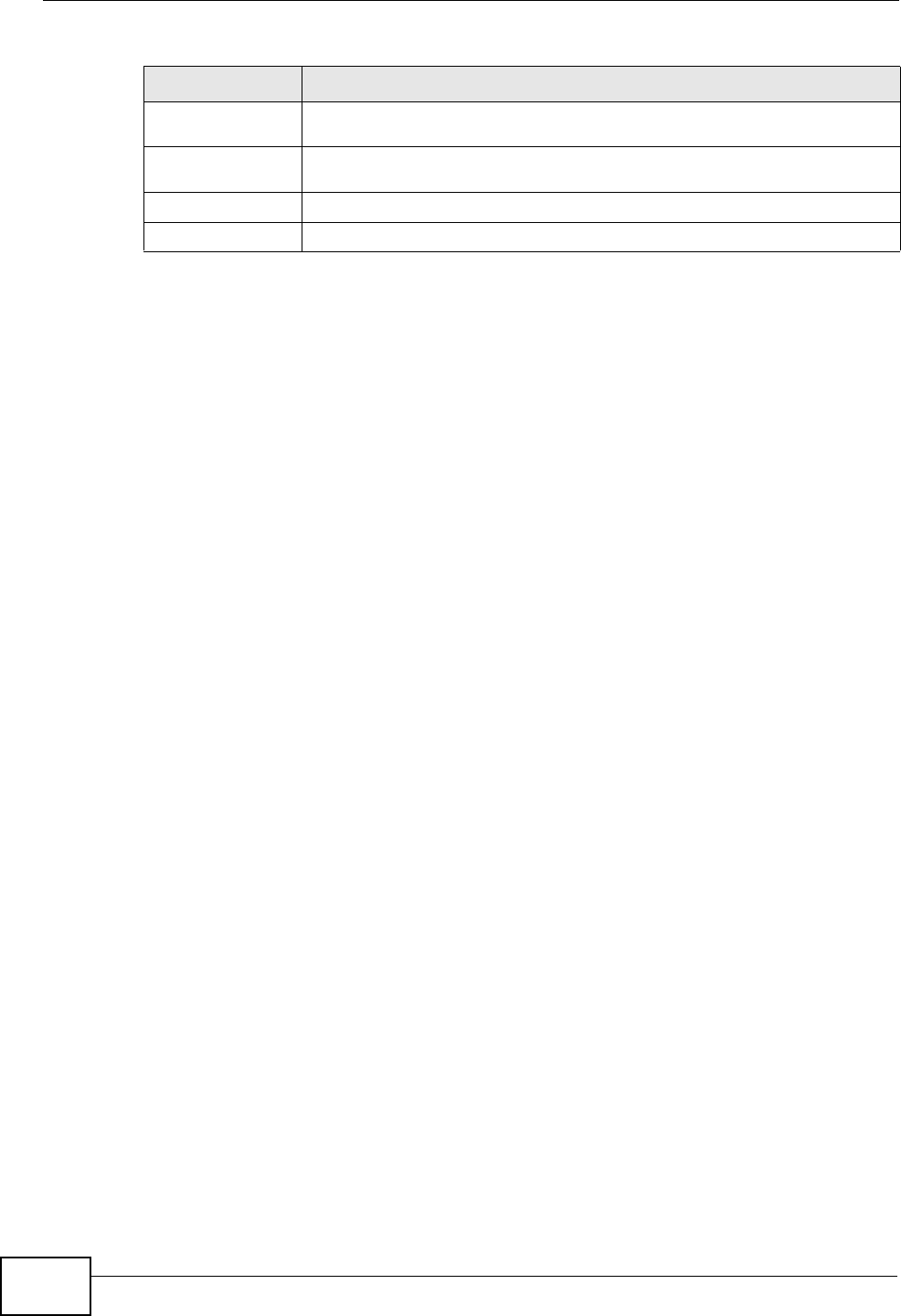
Chapter 5 Broadband
P-2612HNU(L)-FxF User’s Guide
100
5.2.1.2 Routing- IPoE
Click the Add new WAN Interface in the Network Setting > Broadband
screen or the Edit icon next to the connection you want to configure. Select
Routing as the encapsulation mode and IPoE as the WAN service type.
Primary DNS
Server Enter the first DNS server address assigned by the ISP.
Secondary
DNS Server Enter the second DNS server address assigned by the ISP.
Apply Click Apply to save your changes.
Back Click Back to return to the previous screen.
Table 7 Broadband Add/Edit: Routing- PPPoE (continued)
Label DESCRIPTION
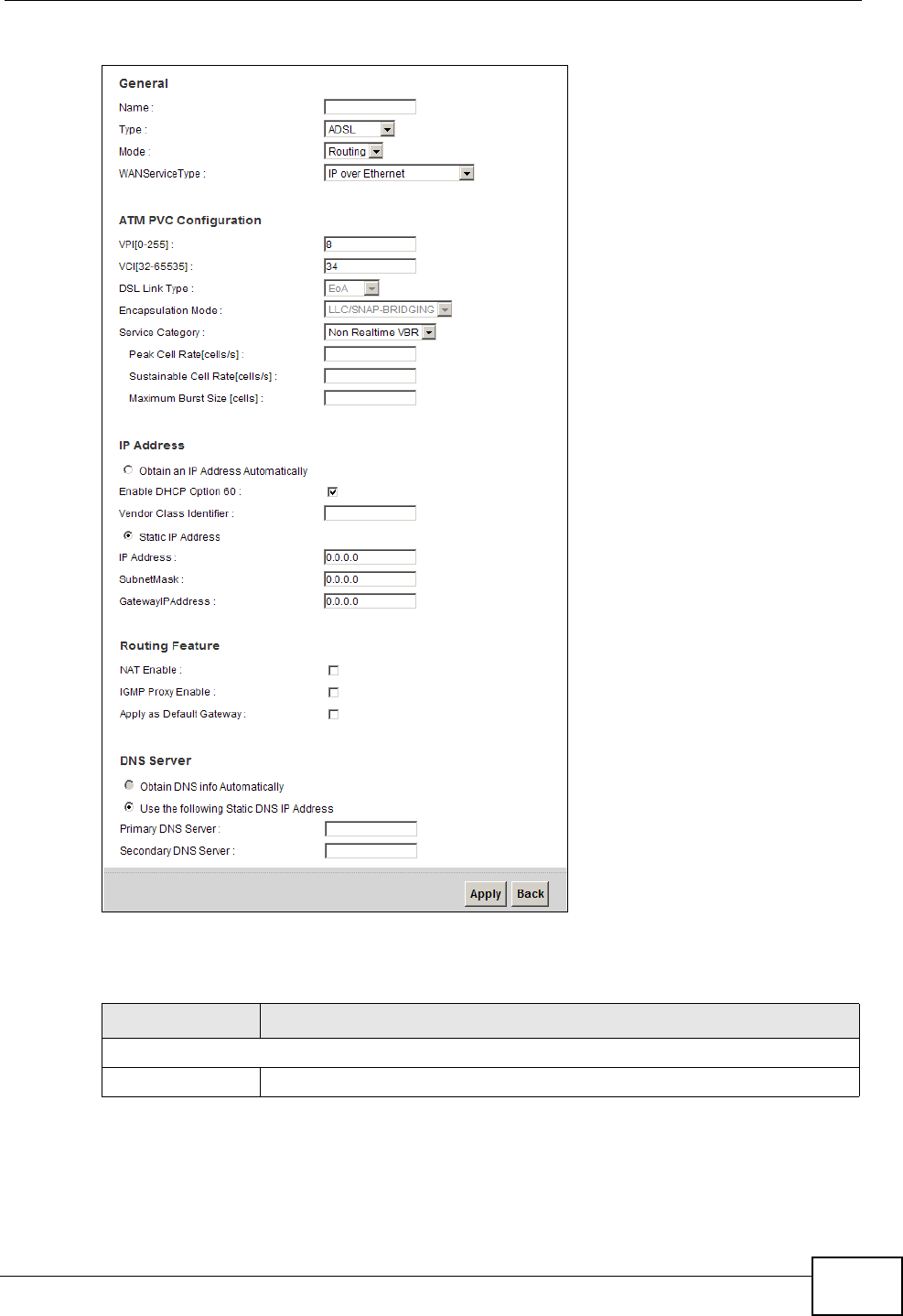
Chapter 5 Broadband
P-2612HNU(L)-FxF User’s Guide 101
Broadband Add/Edit: Routing- IPoE
The following table describes the fields in this screen.
Table 8 Broadband Add/Edit: Routing- IPoE
Label DESCRIPTION
General
Name Enter a service name of the connection.

Chapter 5 Broadband
P-2612HNU(L)-FxF User’s Guide
102
Type Select an interface for which you want to configure here.
ADSL: The ZyXEL Device uses the ADSL technology for data
transmission over the DSL port.
EtherWAN: The ZyXEL Device transmits data over the Ethernet WAN
port. Select this if you have a DSL router or modem in your network
already.
Mode Select Routing (default) from the drop-down list box if your ISP give
you one IP address only and you want multiple computers to share an
Internet account.
WAN Service
Type
This field is available only when you select Routing in the Mode field.
Select the method of encapsulation used by your ISP.
•PPP over Ethernet (PPPoE) - PPPoE (Point to Point Protocol over
Ethernet) provides access control and billing functionality in a
manner similar to dial-up services using PPP. Select this if you have
a username and password for Internet access.
•IP over Ethernet - In this type of Internet connection, IP packets
are routed between the Ethernet interface and the WAN interface
and then formatted so that they can be understood in a bridged
environment.
ATM PVC
Configuration
VPI (Virtual Path Identifier) and VCI (Virtual Channel Identifier) define
a virtual circuit.
This section is available only when you select ADSL in the Type field
to configure an ATM layer-2 interface.
VPI The valid range for the VPI is 0 to 255. Enter the VPI assigned to you.
VCI The valid range for the VCI is 32 to 65535 (0 to 31 is reserved for local
management of ATM traffic). Enter the VCI assigned to you.
DSL Link Type The DSL link type is set to EoA (Ethernet over ATM) to have an
Ethernet header in the packet, so that you can have multiple services/
connections over one PVC. You can set each connection to have its
own MAC address or all connections share one MAC address but use
different VLAN IDs for different services. EoA supports IPoE, PPPoE
and RFC1483/2684 bridging encapsulation methods.
Encapsulation
Mode
The encapsulation method of multiplexing used by your is LLC/SNAP-
BRIDGING. In LCC encapsulation, bridged PDUs are encapsulated by
identifying the type of the bridged media in the SNAP header.
Service Category Select UBR Without PCR for applications that are non-time sensitive,
such as e-mail.
Select CBR (Constant Bit Rate) to specify fixed (always-on) bandwidth
for voice or data traffic.
Select Non Realtime VBR (non real-time Variable Bit Rate) for
connections that do not require closely controlled delay and delay
variation.
Select Realtime VBR (real-time Variable Bit Rate) for applications
with bursty connections that require closely controlled delay and delay
variation.
Table 8 Broadband Add/Edit: Routing- IPoE (continued)
Label DESCRIPTION

Chapter 5 Broadband
P-2612HNU(L)-FxF User’s Guide 103
Peak Cell Rate Divide the DSL line rate (bps) by 424 (the size of an ATM cell) to find
the Peak Cell Rate (PCR). This is the maximum rate at which the
sender can send cells. Type the PCR here.
This field is not available when you select UBR Without PCR.
Sustainable
Cell Rate The Sustain Cell Rate (SCR) sets the average cell rate (long-term) that
can be transmitted. Type the SCR, which must be less than the PCR.
Note that system default is 0 cells/sec.
This field is available only when you select Non Realtime VBR or
Realtime VBR.
Maximum
Burst Size Maximum Burst Size (MBS) refers to the maximum number of cells
that can be sent at the peak rate. Type the MBS, which is less than
65535.
This field is available only when you select Non Realtime VBR or
Realtime VBR.
VLAN This section is available only when you select EtherWAN in the Type
field.
Enable VLAN Select this to add the VLAN tag (specified below) to the outgoing
traffic through this connection.
Enter 802.1P
Priority
IEEE 802.1p defines up to 8 separate traffic types by inserting a tag
into a MAC-layer frame that contains bits to define class of service.
Type the IEEE 802.1p priority level (from 0 to 7) to add to traffic
through this connection. The greater the number, the higher the
priority level.
Enter 802.1Q
VLAN ID
Type the VLAN ID number (from 1 to 4094) for traffic through this
connection.
IP Address This section is available only when you select Routing in the Mode
field and IPoE in the WAN Service Type field.
Obtain an IP
Address
Automatically
A static IP address is a fixed IP that your ISP gives you. A dynamic IP
address is not fixed; the ISP assigns you a different one each time you
connect to the Internet. Select this if you want to get a dynamic IP
address from the ISP.
Enable DHCP
Option 60
Select this to identify the vendor and functionality of the ZyXEL Device
in DHCP requests that the ZyXEL Device sends to a DHCP server when
getting a WAN IP address.
Vendor Class
Identifier Enter the Vendor Class Identifier (Option 60), such as the type of the
hardware or firmware.
Static IP Address Select this option If the ISP assigned a fixed IP address.
IP Address Enter the static IP address provided by your ISP.
Subnet Mask Enter the subnet mask provided by your ISP.
Gateway IP
Address
Enter the gateway IP address provided by your ISP.
Routing Feature
NAT Enable Select this option to activate NAT on this connection.
Table 8 Broadband Add/Edit: Routing- IPoE (continued)
Label DESCRIPTION

Chapter 5 Broadband
P-2612HNU(L)-FxF User’s Guide
104
5.2.1.3 Bridge Mode
Click the Add new WAN Interface in the Network Setting > Broadband
screen or the Edit icon next to the connection you want to configure. Select
Bridge as the encapsulation mode. The screen differs according to the interface
IGMP Proxy
Enable
Internet Group Multicast Protocol (IGMP) is a network-layer protocol
used to establish membership in a Multicast group - it is not used to
carry user data.
Select this option to have the ZyXEL Device act as an IGMP proxy on
this connection. This allows the ZyXEL Device to get subscribing
information and maintain a joined member list for each multicast
group. It can reduce multicast traffic significantly.
Apply as Default
Gateway
Select this option to have the ZyXEL Device use the WAN interface of
this connection as the system default gateway.
DNS Server This is available only when you select Apply as Default Gateway in
the Routing Feature field.
Obtain DNS info
Automatically
Select this to have the ZyXEL Device get the DNS server addresses
from the ISP automatically.
Use the following
Static DNS IP
Address
Select this to have the ZyXEL Device use the DNS server addresses
you configure manually.
Primary DNS
Server Enter the first DNS server address assigned by the ISP.
Secondary
DNS Server Enter the second DNS server address assigned by the ISP.
Apply Click Apply to save your changes.
Back Click Back to return to the previous screen.
Table 8 Broadband Add/Edit: Routing- IPoE (continued)
Label DESCRIPTION
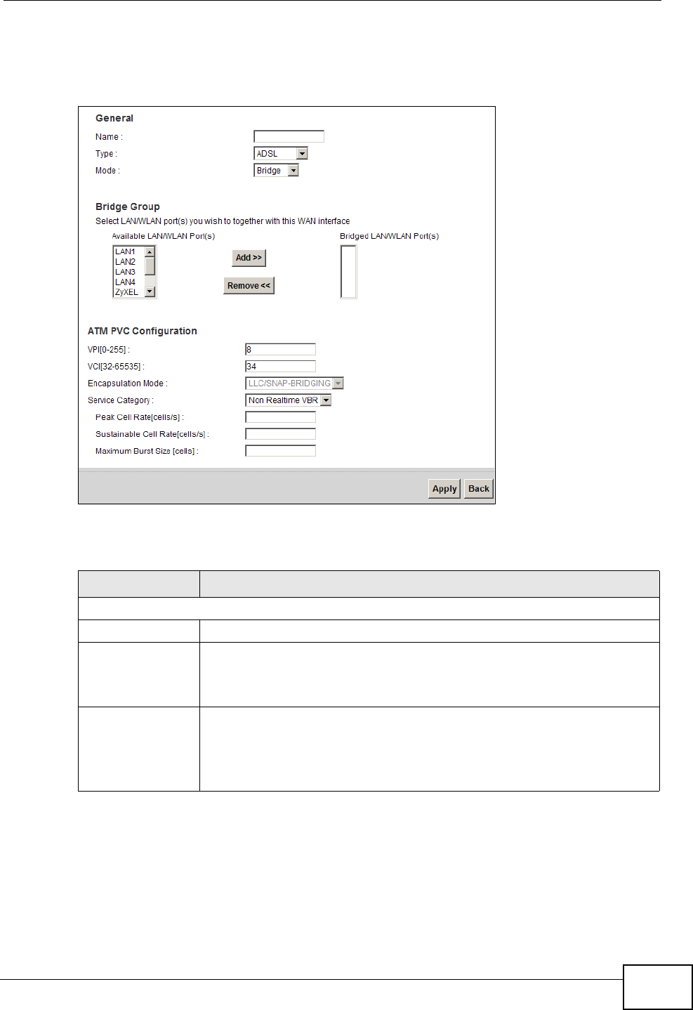
Chapter 5 Broadband
P-2612HNU(L)-FxF User’s Guide 105
type you select. If you select ADSL as the interface type, the following screen
appears.
Figure 18 Broadband Add/Edit: Bridge (ADSL)
The following table describes the fields in this screen.
Table 9 Broadband Add/Edit: Bridge (ADSL)
Label DESCRIPTION
General
Name Enter a service name of the connection.
Type Select ADSL as the interface for which you want to configure here.
The ZyXEL Device uses the ADSL technology for data transmission
over the DSL port.
Mode Select Bridge when your ISP provides you more than one IP address
and you want the connected computers to get individual IP address
from ISP’s DHCP server directly. If you select Bridge, you cannot use
routing functions, such as QoS, Firewall, DHCP server and NAT on
traffic from the selected LAN port(s).
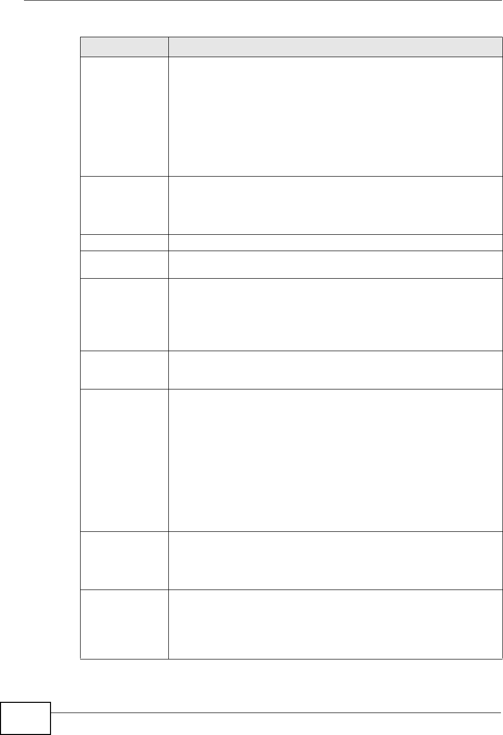
Chapter 5 Broadband
P-2612HNU(L)-FxF User’s Guide
106
Bridge Group Select the LAN/WLAN port(s) from which traffic will be forwarded to
the WAN interface directly.
Select a port from the Available LAN/WLAN Port(s) list and click
Add >> to add it to the Bridged LAN/WLAN Port(s) list.
If you want to remove a port from the Bridged LAN/WLAN Port(s)
list, select it and click Remove <<.
You cannot configure a QoS class for traffic from the LAN port which is
selected here.
ATM PVC
Configuration
VPI (Virtual Path Identifier) and VCI (Virtual Channel Identifier) define
a virtual circuit.
This section is available only when you select ADSL in the Type field
to configure an ATM layer-2 interface.
VPI The valid range for the VPI is 0 to 255. Enter the VPI assigned to you.
VCI The valid range for the VCI is 32 to 65535 (0 to 31 is reserved for local
management of ATM traffic). Enter the VCI assigned to you.
DSL Link Type The DSL link type is set to EoA (Ethernet over ATM) to have an
Ethernet header in the packet, so that you can have multiple services/
connections over one PVC. You can set each connection to have its
own MAC address or all connections share one MAC address but use
different VLAN IDs for different services. EoA supports IPoE, PPPoE
and RFC1483/2684 bridging encapsulation methods.
Encapsulation
Mode
The encapsulation method of multiplexing used by your is LLC/SNAP-
BRIDGING. In LCC encapsulation, bridged PDUs are encapsulated by
identifying the type of the bridged media in the SNAP header.
Service Category Select UBR Without PCR for applications that are non-time sensitive,
such as e-mail.
Select CBR (Constant Bit Rate) to specify fixed (always-on) bandwidth
for voice or data traffic.
Select Non Realtime VBR (non real-time Variable Bit Rate) for
connections that do not require closely controlled delay and delay
variation.
Select Realtime VBR (real-time Variable Bit Rate) for applications
with bursty connections that require closely controlled delay and delay
variation.
Peak Cell Rate Divide the DSL line rate (bps) by 424 (the size of an ATM cell) to find
the Peak Cell Rate (PCR). This is the maximum rate at which the
sender can send cells. Type the PCR here.
This field is not available when you select UBR Without PCR.
Sustainable
Cell Rate The Sustain Cell Rate (SCR) sets the average cell rate (long-term) that
can be transmitted. Type the SCR, which must be less than the PCR.
Note that system default is 0 cells/sec.
This field is available only when you select Non Realtime VBR or
Realtime VBR.
Table 9 Broadband Add/Edit: Bridge (ADSL) (continued)
Label DESCRIPTION
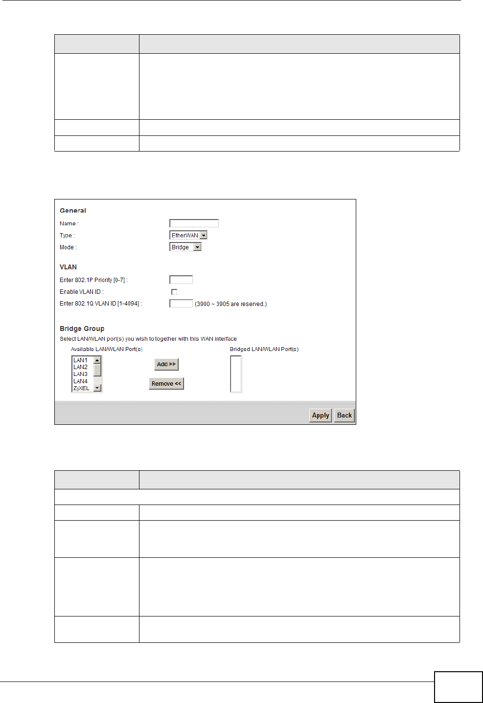
Chapter 5 Broadband
P-2612HNU(L)-FxF User’s Guide 107
If you select EtherWAN as the interface type, the following screen appears.
Figure 19 Broadband Add/Edit: Bridge (Ethernet)
The following table describes the fields in this screen.
Maximum
Burst Size Maximum Burst Size (MBS) refers to the maximum number of cells
that can be sent at the peak rate. Type the MBS, which is less than
65535.
This field is available only when you select Non Realtime VBR or
Realtime VBR.
Apply Click Apply to save your changes.
Back Click Back to return to the previous screen.
Table 10 Broadband Add/Edit: Bridge (Ethernet)
Label DESCRIPTION
General
Name Enter a service name of the connection.
Type Select EtherWAN as the interface for which you want to configure The
ZyXEL Device transmits data over the Ethernet WAN port. Select this if
you have a DSL router or modem in your network already.
Mode Select Bridge when your ISP provides you more than one IP address
and you want the connected computers to get individual IP address
from ISP’s DHCP server directly. If you select Bridge, you cannot use
routing functions, such as QoS, Firewall, DHCP server and NAT on
traffic from the selected LAN port(s).
VLAN This section is available only when you select EtherWAN in the Type
field.
Table 9 Broadband Add/Edit: Bridge (ADSL) (continued)
Label DESCRIPTION
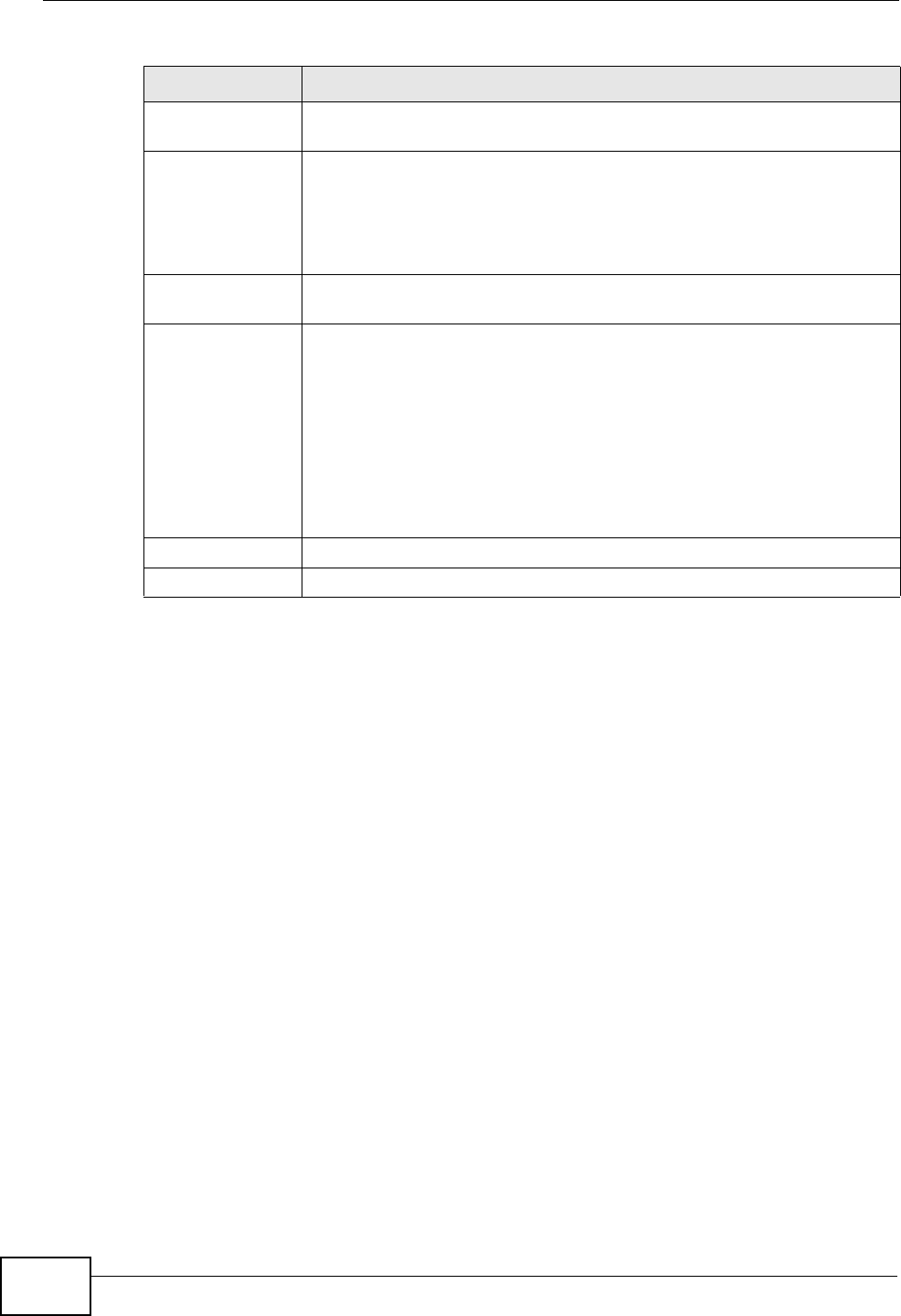
Chapter 5 Broadband
P-2612HNU(L)-FxF User’s Guide
108
5.3 The 3G Backup Screen
Use this screen to configure your 3G settings. Click Broadband > 3G Backup.
At the time of writing, the 3G card you can use in the ZyXEL Device is Huawei
E220.
Note: The actual data rate you obtain varies depending the 3G card you use, the
signal strength to the service provider’s base station, and so on.
Enable VLAN Select this to add the VLAN Tag (specified below) to the outgoing
traffic through this connection.
Enter 802.1P
Priority
IEEE 802.1p defines up to 8 separate traffic types by inserting a tag
into a MAC-layer frame that contains bits to define class of service.
Type the IEEE 802.1p priority level (from 0 to 7) to add to traffic
through this connection. The greater the number, the higher the
priority level.
Enter 802.1Q
VLAN ID
Type the VLAN ID number (from 1 to 4094) for traffic through this
connection.
Bridge Group Select the LAN/WLAN port(s) from which traffic will be forwarded to
the WAN interface directly.
Select a port from the Available LAN/WLAN Port(s) list and click
Add >> to add it to the Bridged LAN/WLAN Port(s) list.
If you want to remove a port from the Bridged LAN/WLAN Port(s)
list, select it and click Remove <<.
You cannot configure a QoS class for traffic from the LAN port which is
selected here.
Apply Click Apply to save your changes.
Back Click Back to return to the previous screen.
Table 10 Broadband Add/Edit: Bridge (Ethernet) (continued)
Label DESCRIPTION
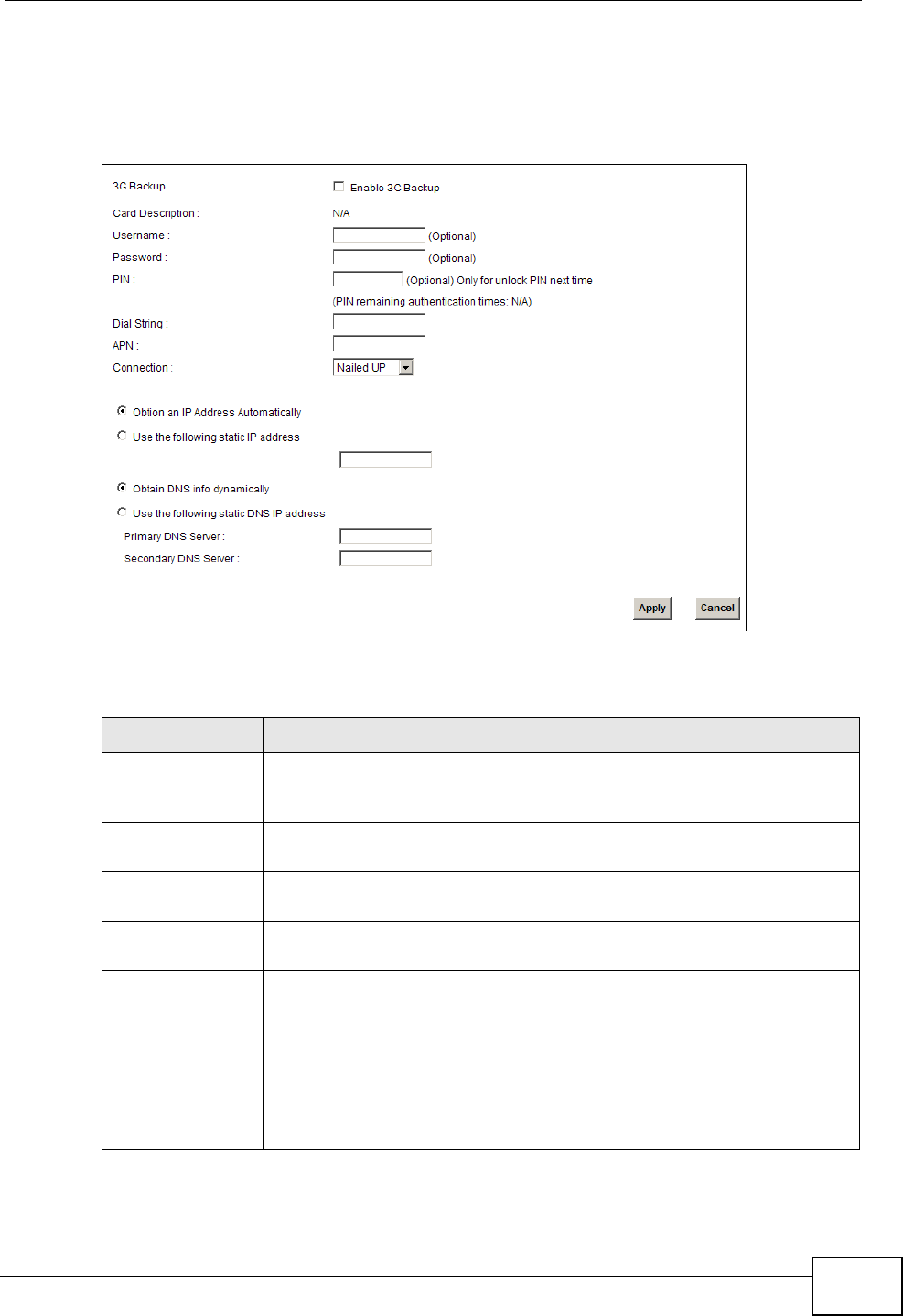
Chapter 5 Broadband
P-2612HNU(L)-FxF User’s Guide 109
If the signal strength of a 3G network is too low, the 3G card may switch to an
available 2.5G or 2.75G network. Refer to Section 5.4 on page 110 for a
comparison between 2G, 2.5G, 2.75G and 3G wireless technologies.
Figure 20 Broadband > 3G Backup
The following table describes the labels in this screen.
Table 11 Broadband > 3G Backup
LABEL DESCRIPTION
3G Backup Select Enable 3G Backup to have the ZyXEL Device use the 3G
connection as your WAN or a backup when the wired WAN connection
fails.
Card Description This field displays the manufacturer and model name of your 3G card
if you inserted one in the ZyXEL Device. Otherwise, it displays N/A.
Username Type the user name (of up to 70 ASCII printable characters) given to
you by your service provider.
Password Type the password (of up to 70 ASCII printable characters) associated
with the user name above.
PIN A PIN (Personal Identification Number) code is a key to a 3G card.
Without the PIN code, you cannot use the 3G card.
If your ISP enabled PIN code authentication, enter the 4-digit PIN
code (0000 for example) provided by your ISP. If you enter the PIN
code incorrectly, the 3G card may be blocked by your ISP and you
cannot use the account to access the Internet.
If your ISP disabled PIN code authentication, leave this field blank.
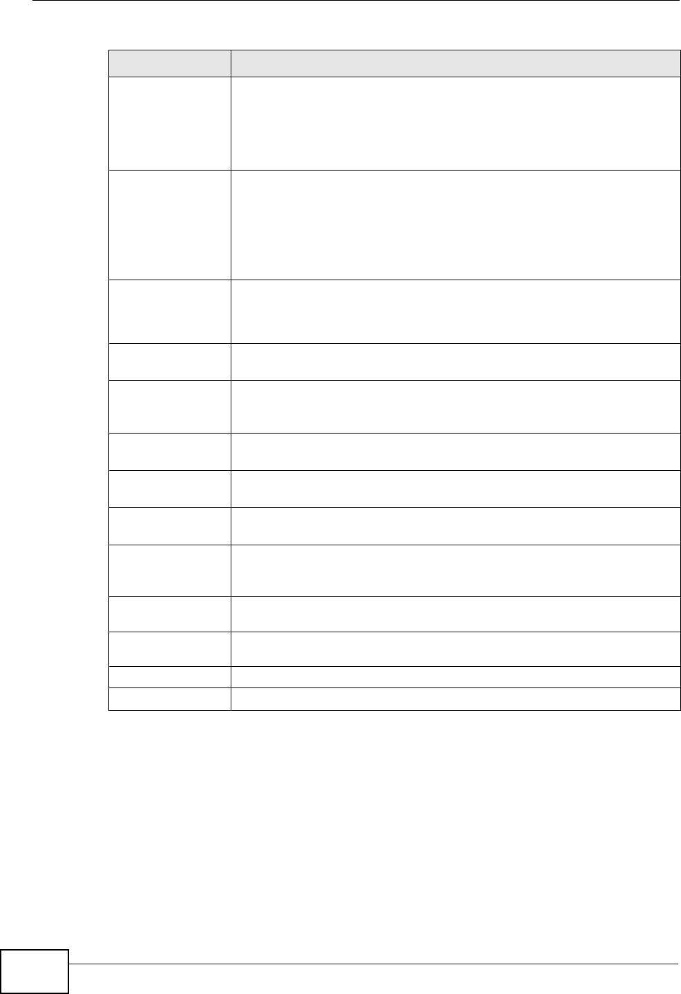
Chapter 5 Broadband
P-2612HNU(L)-FxF User’s Guide
110
5.4 Technical Reference
The following section contains additional technical information about the ZyXEL
Device features described in this chapter.
Dial String Enter the phone number (dial string) used to dial up a connection to
your service provider’s base station. Your ISP should provide the
phone number.
For example, *99# is the dial string to establish a GPRS or 3G
connection in Taiwan.
APN Code Enter the APN (Access Point Name) provided by your service provider.
Connections with different APNs may provide different services (such
as Internet access or MMS (Multi-Media Messaging Service)) and
charge method.
You can enter up to 31 ASCII printable characters. Spaces are
allowed.
Connection Select Nailed-UP if you do not want the connection to time out.
Select On-Demand if you do not want the connection up all the time
and specify an idle time-out in the Max Idle Timeout field.
Max Idle Timeout This value specifies the time in minutes that elapses before the ZyXEL
Device automatically disconnects from the ISP.
Obtain an IP
Address
Automatically
Select this option If your ISP did not assign you a fixed IP address.
Use the following
static IP address
Select this option If the ISP assigned a fixed IP address.
IP Address Enter your WAN IP address in this field if you selected Use the
following static IP address.
Obtain DNS info
dynamically
Select this to have the ZyXEL Device get the DNS server addresses
from the ISP automatically.
Use the following
static DNS IP
address
Select this to have the ZyXEL Device use the DNS server addresses
you configure manually.
Primary DNS
server Enter the first DNS server address assigned by the ISP.
Secondary
DNS server Enter the second DNS server address assigned by the ISP.
Apply Click Apply to save your changes back to the ZyXEL Device.
Cancel Click Cancel to return to the previous configuration.
Table 11 Broadband > 3G Backup (continued)
LABEL DESCRIPTION

Chapter 5 Broadband
P-2612HNU(L)-FxF User’s Guide 111
Encapsulation
Be sure to use the encapsulation method required by your ISP. The ZyXEL Device
can work in bridge mode or routing mode. When the ZyXEL Device is in routing
mode, it supports the following methods.
IP over Ethernet
IP over Ethernet (IPoE) is an alternative to PPPoE. IP packets are being delivered
across an Ethernet network, without using PPP encapsulation. They are routed
between the Ethernet interface and the WAN interface and then formatted so that
they can be understood in a bridged environment. For instance, it encapsulates
routed Ethernet frames into bridged Ethernet cells.
PPP over Ethernet
Point-to-Point Protocol over Ethernet (PPPoE) provides access control and billing
functionality in a manner similar to dial-up services using PPP. PPPoE is an IETF
standard (RFC 2516) specifying how a personal computer (PC) interacts with a
broadband modem (DSL, cable, wireless, etc.) connection.
For the service provider, PPPoE offers an access and authentication method that
works with existing access control systems (for example RADIUS).
One of the benefits of PPPoE is the ability to let you access one of multiple network
services, a function known as dynamic service selection. This enables the service
provider to easily create and offer new IP services for individuals.
Operationally, PPPoE saves significant effort for both you and the ISP or carrier, as
it requires no specific configuration of the broadband modem at the customer site.
By implementing PPPoE directly on the ZyXEL Device (rather than individual
computers), the computers on the LAN do not need PPPoE software installed,
since the ZyXEL Device does that part of the task. Furthermore, with NAT, all of
the LANs’ computers will have access.
RFC 1483
RFC 1483 describes two methods for Multiprotocol Encapsulation over ATM
Adaptation Layer 5 (AAL5). The first method allows multiplexing of multiple
protocols over a single ATM virtual circuit (LLC-based multiplexing) and the second
method assumes that each protocol is carried over a separate ATM virtual circuit
(VC-based multiplexing). Please refer to RFC 1483 for more detailed information.

Chapter 5 Broadband
P-2612HNU(L)-FxF User’s Guide
112
Multiplexing
There are two conventions to identify what protocols the virtual circuit (VC) is
carrying. Be sure to use the multiplexing method required by your ISP.
VC-based Multiplexing
In this case, by prior mutual agreement, each protocol is assigned to a specific
virtual circuit; for example, VC1 carries IP, etc. VC-based multiplexing may be
dominant in environments where dynamic creation of large numbers of ATM VCs is
fast and economical.
LLC-based Multiplexing
In this case one VC carries multiple protocols with protocol identifying information
being contained in each packet header. Despite the extra bandwidth and
processing overhead, this method may be advantageous if it is not practical to
have a separate VC for each carried protocol, for example, if charging heavily
depends on the number of simultaneous VCs.
Traffic Shaping
Traffic Shaping is an agreement between the carrier and the subscriber to regulate
the average rate and fluctuations of data transmission over an ATM network. This
agreement helps eliminate congestion, which is important for transmission of real
time data such as audio and video connections.
Peak Cell Rate (PCR) is the maximum rate at which the sender can send cells. This
parameter may be lower (but not higher) than the maximum line speed. 1 ATM
cell is 53 bytes (424 bits), so a maximum speed of 832Kbps gives a maximum
PCR of 1962 cells/sec. This rate is not guaranteed because it is dependent on the
line speed.
Sustained Cell Rate (SCR) is the mean cell rate of each bursty traffic source. It
specifies the maximum average rate at which cells can be sent over the virtual
connection. SCR may not be greater than the PCR.
Maximum Burst Size (MBS) is the maximum number of cells that can be sent at
the PCR. After MBS is reached, cell rates fall below SCR until cell rate averages to
the SCR again. At this time, more cells (up to the MBS) can be sent at the PCR
again.
If the PCR, SCR or MBS is set to the default of "0", the system will assign a
maximum value that correlates to your upstream line rate.
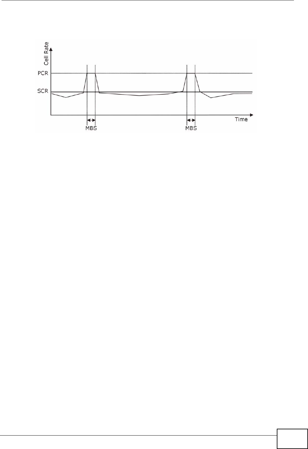
Chapter 5 Broadband
P-2612HNU(L)-FxF User’s Guide 113
The following figure illustrates the relationship between PCR, SCR and MBS.
Figure 21 Example of Traffic Shaping
ATM Traffic Classes
These are the basic ATM traffic classes defined by the ATM Forum Traffic
Management 4.0 Specification.
Constant Bit Rate (CBR)
Constant Bit Rate (CBR) provides fixed bandwidth that is always available even if
no data is being sent. CBR traffic is generally time-sensitive (doesn't tolerate
delay). CBR is used for connections that continuously require a specific amount of
bandwidth. A PCR is specified and if traffic exceeds this rate, cells may be
dropped. Examples of connections that need CBR would be high-resolution video
and voice.
Variable Bit Rate (VBR)
The Variable Bit Rate (VBR) ATM traffic class is used with bursty connections.
Connections that use the Variable Bit Rate (VBR) traffic class can be grouped into
real time (VBR-RT) or non-real time (VBR-nRT) connections.
The VBR-RT (real-time Variable Bit Rate) type is used with bursty connections that
require closely controlled delay and delay variation. It also provides a fixed
amount of bandwidth (a PCR is specified) but is only available when data is being
sent. An example of an VBR-RT connection would be video conferencing. Video
conferencing requires real-time data transfers and the bandwidth requirement
varies in proportion to the video image's changing dynamics.
The VBR-nRT (non real-time Variable Bit Rate) type is used with bursty
connections that do not require closely controlled delay and delay variation. It is
commonly used for "bursty" traffic typical on LANs. PCR and MBS define the burst
levels, SCR defines the minimum level. An example of an VBR-nRT connection
would be non-time sensitive data file transfers.

Chapter 5 Broadband
P-2612HNU(L)-FxF User’s Guide
114
Unspecified Bit Rate (UBR)
The Unspecified Bit Rate (UBR) ATM traffic class is for bursty data transfers.
However, UBR doesn't guarantee any bandwidth and only delivers traffic when the
network has spare bandwidth. An example application is background file transfer.
IP Address Assignment
A static IP is a fixed IP that your ISP gives you. A dynamic IP is not fixed; the ISP
assigns you a different one each time. The Single User Account feature can be
enabled or disabled if you have either a dynamic or static IP. However the
encapsulation method assigned influences your choices for IP address and default
gateway.
Introduction to VLANs
A Virtual Local Area Network (VLAN) allows a physical network to be partitioned
into multiple logical networks. Devices on a logical network belong to one group. A
device can belong to more than one group. With VLAN, a device cannot directly
talk to or hear from devices that are not in the same group(s); the traffic must
first go through a router.
In Multi-Tenant Unit (MTU) applications, VLAN is vital in providing isolation and
security among the subscribers. When properly configured, VLAN prevents one
subscriber from accessing the network resources of another on the same LAN,
thus a user will not see the printers and hard disks of another user in the same
building.
VLAN also increases network performance by limiting broadcasts to a smaller and
more manageable logical broadcast domain. In traditional switched environments,
all broadcast packets go to each and every individual port. With VLAN, all
broadcasts are confined to a specific broadcast domain.
Introduction to IEEE 802.1Q Tagged VLAN
A tagged VLAN uses an explicit tag (VLAN ID) in the MAC header to identify the
VLAN membership of a frame across bridges - they are not confined to the switch
on which they were created. The VLANs can be created statically by hand or
dynamically through GVRP. The VLAN ID associates a frame with a specific VLAN
and provides the information that switches need to process the frame across the
network. A tagged frame is four bytes longer than an untagged frame and
contains two bytes of TPID (Tag Protocol Identifier), residing within the type/
length field of the Ethernet frame) and two bytes of TCI (Tag Control Information),
starts after the source address field of the Ethernet frame).

Chapter 5 Broadband
P-2612HNU(L)-FxF User’s Guide 115
The CFI (Canonical Format Indicator) is a single-bit flag, always set to zero for
Ethernet switches. If a frame received at an Ethernet port has a CFI set to 1, then
that frame should not be forwarded as it is to an untagged port. The remaining
twelve bits define the VLAN ID, giving a possible maximum number of 4,096
VLANs. Note that user priority and VLAN ID are independent of each other. A
frame with VID (VLAN Identifier) of null (0) is called a priority frame, meaning that
only the priority level is significant and the default VID of the ingress port is given
as the VID of the frame. Of the 4096 possible VIDs, a VID of 0 is used to identify
priority frames and value 4095 (FFF) is reserved, so the maximum possible VLAN
configurations are 4,094.
Multicast
IP packets are transmitted in either one of two ways - Unicast (1 sender - 1
recipient) or Broadcast (1 sender - everybody on the network). Multicast delivers
IP packets to a group of hosts on the network - not everybody and not just 1.
Internet Group Multicast Protocol (IGMP) is a network-layer protocol used to
establish membership in a Multicast group - it is not used to carry user data. IGMP
version 2 (RFC 2236) is an improvement over version 1 (RFC 1112) but IGMP
version 1 is still in wide use. If you would like to read more detailed information
about interoperability between IGMP version 2 and version 1, please see sections
4 and 5 of RFC 2236. The class D IP address is used to identify host groups and
can be in the range 224.0.0.0 to 239.255.255.255. The address 224.0.0.0 is not
assigned to any group and is used by IP multicast computers. The address
224.0.0.1 is used for query messages and is assigned to the permanent group of
all IP hosts (including gateways). All hosts must join the 224.0.0.1 group in order
to participate in IGMP. The address 224.0.0.2 is assigned to the multicast routers
group.
At start up, the ZyXEL Device queries all directly connected networks to gather
group membership. After that, the ZyXEL Device periodically updates this
information.
DNS Server Address Assignment
Use Domain Name System (DNS) to map a domain name to its corresponding IP
address and vice versa, for instance, the IP address of www.zyxel.com is
204.217.0.2. The DNS server is extremely important because without it, you must
know the IP address of a computer before you can access it.
The ZyXEL Device can get the DNS server addresses in the following ways.
TPID
2 Bytes
User Priority
3 Bits
CFI
1 Bit
VLAN ID
12 Bits

Chapter 5 Broadband
P-2612HNU(L)-FxF User’s Guide
116
1The ISP tells you the DNS server addresses, usually in the form of an information
sheet, when you sign up. If your ISP gives you DNS server addresses, manually
enter them in the DNS server fields.
2If your ISP dynamically assigns the DNS server IP addresses (along with the
ZyXEL Device’s WAN IP address), set the DNS server fields to get the DNS server
address from the ISP.
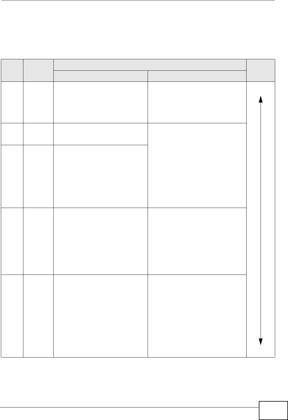
Chapter 5 Broadband
P-2612HNU(L)-FxF User’s Guide 117
3G Comparison Table
See the following table for a comparison between 2G, 2.5G, 2.75G and 3G
wireless technologies.
Table 12 2G, 2.5G, 2.75G, 3G and 3.5G Wireless Technologies
NAME TYPE
MOBILE PHONE AND DATA STANDARDS DATA
SPEED
GSM-BASED CDMA-BASED
2G Circuit-
switched
GSM (Global System for Mobile
Communications), Personal
Handy-phone System (PHS), etc.
Interim Standard 95 (IS-95), the
first CDMA-based digital cellular
standard pioneered by Qualcomm.
The brand name for IS-95 is
cdmaOne. IS-95 is also known as
TIA-EIA-95.
Slow
Fast
2.5G Packet-
switched
GPRS (General Packet Radio
Services), High-Speed Circuit-
Switched Data (HSCSD), etc.
CDMA2000 is a hybrid 2.5G / 3G
protocol of mobile
telecommunications standards that
use CDMA, a multiple access
scheme for digital radio.
CDMA2000 1xRTT (1 times Radio
Transmission Technology) is the
core CDMA2000 wireless air
interface standard. It is also known
as 1x, 1xRTT, or IS-2000 and
considered to be a 2.5G or 2.75G
technology.
2.75G Packet-
switched
Enhanced Data rates for GSM
Evolution (EDGE), Enhanced
GPRS (EGPRS), etc.
3G Packet-
switched
UMTS (Universal Mobile
Telecommunications System), a
third-generation (3G) wireless
standard defined in ITUA
specification, is sometimes
marketed as 3GSM. The UMTS
uses GSM infrastructures and W-
CDMA (Wideband Code Division
Multiple Access) as the air
interface.
CDMA2000 EV-DO (Evolution-Data
Optimized, originally 1x Evolution-
Data Only), also referred to as EV-
DO, EVDO, or just EV, is an
evolution of CDMA2000 1xRTT and
enables high-speed wireless
connectivity. It is also denoted as
IS-856 or High Data Rate (HDR).
3.5G Packet-
switched
HSDPA (High-Speed Downlink
Packet Access) is a mobile
telephony protocol, used for
UMTS-based 3G networks and
allows for higher data transfer
speeds.
A. The International Telecommunication Union (ITU) is an international organization within which governments and the private sector
coordinate global telecom networks and services.

Chapter 5 Broadband
P-2612HNU(L)-FxF User’s Guide
118

P-2612HNU(L)-FxF User’s Guide 119
CHAPTER 6
Wireless
6.1 Overview
This chapter describes the ZyXEL Device’s Network Setting > Wireless screens.
Use these screens to set up your ZyXEL Device’s wireless connection.
6.1.1 What You Can Do in this Chapter
• Use the General screen to enable the Wireless LAN, enter the SSID and select
the wireless security mode (Section 6.2 on page 121).
• Use the More AP screen to set up multiple wireless networks on your ZyXEL
Device (Section 6.3 on page 129).
• Use the WPS screen to enable or disable WPS, view or generate a security PIN
(Personal Identification Number) (Section 6.4 on page 131).
• Use the WMM screen to enable Wi-Fi MultiMedia (WMM) to ensure quality of
service in wireless networks for multimedia applications (Section 6.5 on page
133).
• Use the Scheduling screen to schedule a time period for the wireless LAN to
operate each day (Section 6.6 on page 135).
You don’t necessarily need to use all these screens to set up your wireless
connection. For example, you may just want to set up a network name, a wireless
radio channel and some security in the General screen.
6.1.2 Wireless Network Overview
Wireless networks consist of wireless clients, access points and bridges.
• A wireless client is a radio connected to a user’s computer.
• An access point is a radio with a wired connection to a network, which can
connect with numerous wireless clients and let them access the network.
• A bridge is a radio that relays communications between access points and
wireless clients, extending a network’s range.
Traditionally, a wireless network operates in one of two ways.
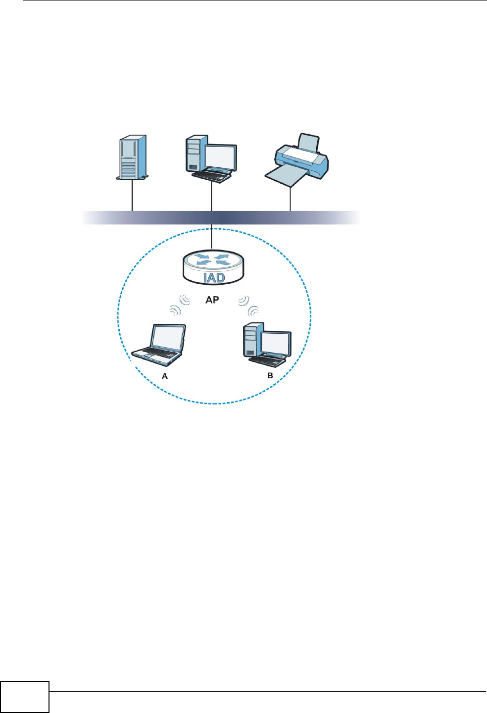
Chapter 6 Wireless
P-2612HNU(L)-FxF User’s Guide
120
• An “infrastructure” type of network has one or more access points and one or
more wireless clients. The wireless clients connect to the access points.
• An “ad-hoc” type of network is one in which there is no access point. Wireless
clients connect to one another in order to exchange information.
The following figure provides an example of a wireless network.
Figure 22 Example of a Wireless Network
The wireless network is the part in the blue circle. In this wireless network,
devices A and B use the access point (AP) to interact with the other devices (such
as the printer) or with the Internet. Your ZyXEL Device is the AP.
Every wireless network must follow these basic guidelines.
• Every device in the same wireless network must use the same SSID.
The SSID is the name of the wireless network. It stands for Service Set
IDentifier.
• If two wireless networks overlap, they should use a different channel.
Like radio stations or television channels, each wireless network uses a specific
channel, or frequency, to send and receive information.
• Every device in the same wireless network must use security compatible with
the AP.
• Security stops unauthorized devices from using the wireless network. It can also
protect the information that is sent in the wireless network.

Chapter 6 Wireless
P-2612HNU(L)-FxF User’s Guide 121
Radio Channels
In the radio spectrum, there are certain frequency bands allocated for unlicensed,
civilian use. For the purposes of wireless networking, these bands are divided into
numerous channels. This allows a variety of networks to exist in the same place
without interfering with one another. When you create a network, you must select
a channel to use.
Since the available unlicensed spectrum varies from one country to another, the
number of available channels also varies.
6.1.3 Before You Begin
Before you start using these screens, ask yourself the following questions. See
Section 6.7 on page 135 if some of the terms used here do not make sense to
you.
• What wireless standards do the other wireless devices support (IEEE 802.11g,
for example)? What is the most appropriate standard to use?
• What security options do the other wireless devices support (WPA-PSK, for
example)? What is the best one to use?
• Do the other wireless devices support WPS (Wi-Fi Protected Setup)? If so, you
can set up a well-secured network very easily.
Even if some of your devices support WPS and some do not, you can use WPS to
set up your network and then add the non-WPS devices manually, although this
is somewhat more complicated to do.
• What advanced options do you want to configure, if any? If you want to
configure advanced options, ensure that you know precisely what you want to
do. If you do not want to configure advanced options, leave them alone.
6.2 The Wireless General Screen
Use this screen to enable the Wireless LAN, enter the SSID and select the wireless
security mode.
Note: If you are configuring the ZyXEL Device from a computer connected to the
wireless LAN and you change the ZyXEL Device’s SSID or security settings,
you will lose your wireless connection when you press Apply to confirm. You
must then change the wireless settings of your computer to match the ZyXEL
Device’s new settings.
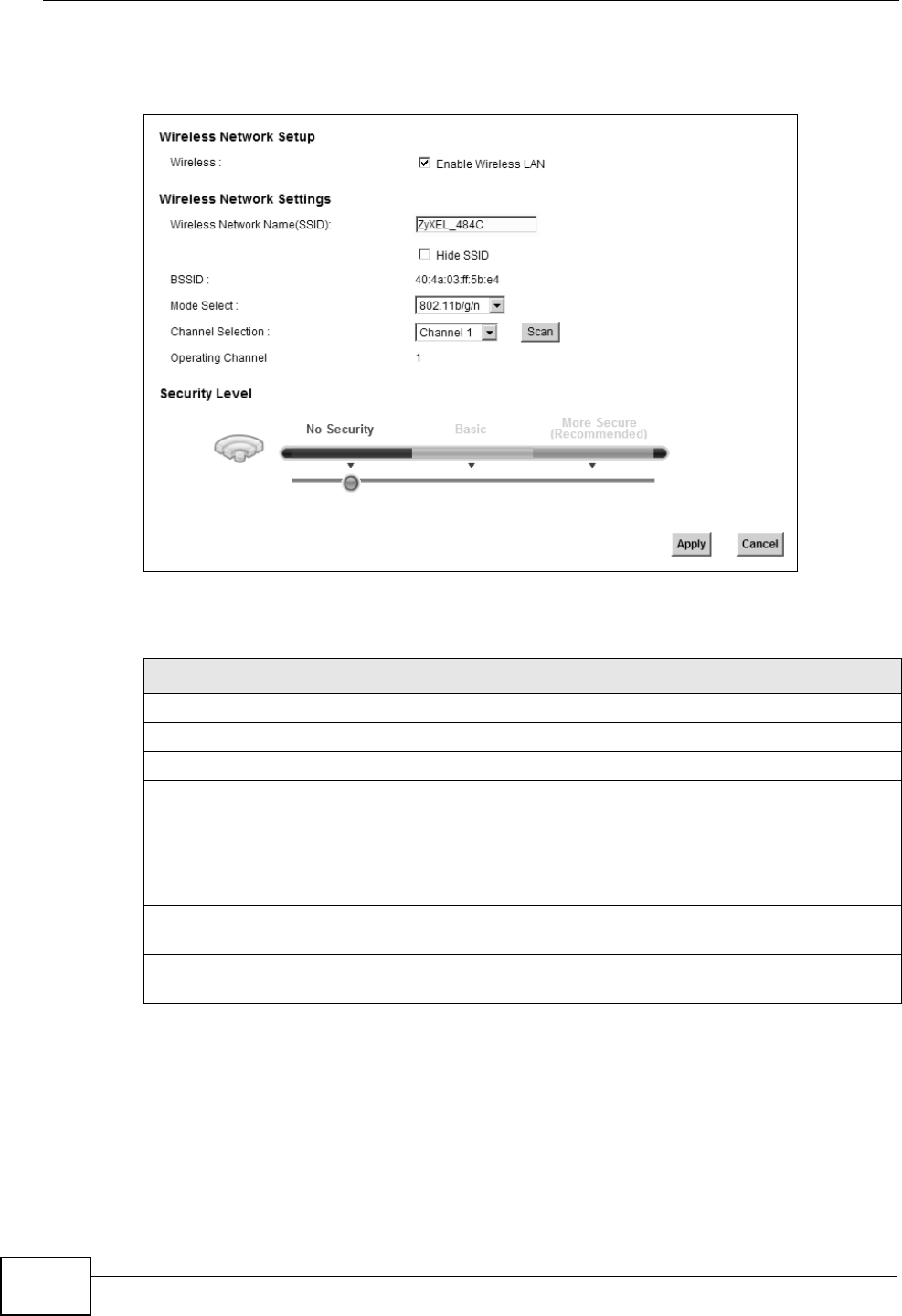
Chapter 6 Wireless
P-2612HNU(L)-FxF User’s Guide
122
Click Network Setting > Wireless to open the General screen.
Figure 23 Network Setting > Wireless > General
The following table describes the labels in this screen.
Table 13 Network > Wireless LAN > General
LABEL DESCRIPTION
Wireless Network Setup
Wireless Select the Enable Wireless LAN check box to activate the wireless LAN.
Wireless Network Settings
Wireless
Network
Name (SSID)
The SSID (Service Set IDentity) identifies the service set with which a
wireless device is associated. Wireless devices associating to the access
point (AP) must have the same SSID.
Enter a descriptive name (up to 32 English keyboard characters) for the
wireless LAN.
Hide SSID Select this check box to hide the SSID in the outgoing beacon frame so a
station cannot obtain the SSID through scanning using a site survey tool.
BSSID This shows the MAC address of the wireless interface on the ZyXEL Device
when wireless LAN is enabled.
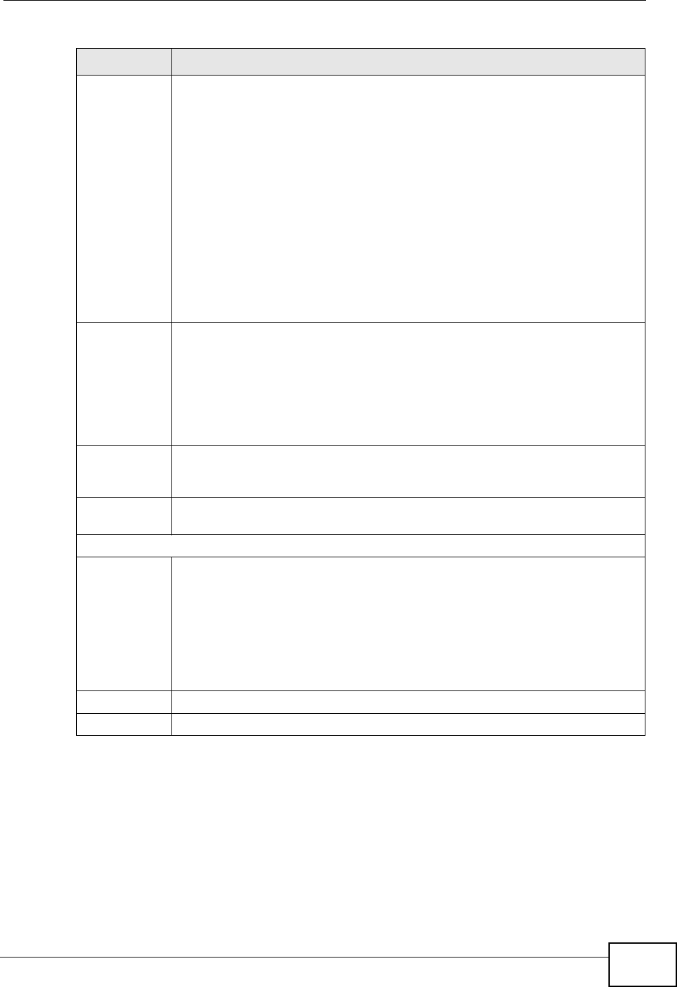
Chapter 6 Wireless
P-2612HNU(L)-FxF User’s Guide 123
6.2.1 No Security
Select No Security to allow wireless stations to communicate with the access
points without any data encryption or authentication.
Mode Select This makes sure that only compliant WLAN devices can associate with the
ZyXEL Device.
Select 802.11b/g/n to allow IEEE802.11b, IEEE802.11g and
IEEE802.11n compliant WLAN devices to associate with the ZyXEL Device.
The transmission rate of your ZyXEL Device might be reduced.
Select 802.11b/g to allow both IEEE802.11b and IEEE802.11g compliant
WLAN devices to associate with the ZyXEL Device. The transmission rate
of your ZyXEL Device might be reduced.
Select 802.11g Only to allow only IEEE 802.11g compliant WLAN devices
to associate with the ZyXEL Device.
Select 802.11n only in 2.4G band to allow only IEEE 802.11n compliant
WLAN devices with the same frequency range (2.4 GHz) to associate with
the ZyXEL Device.
Channel
Selection
Set the channel depending on your particular region.
Select a channel or use Auto to have the ZyXEL Device automatically
determine a channel to use. If you are having problems with wireless
interference, changing the channel may help. Try to use a channel that is
as many channels away from any channels used by neighboring APs as
possible. The channel number which the ZyXEL Device is currently using
then displays in the Operating Channel field.
Scan Click this button to have the ZyXEL Device immediately scan for and select
a channel (which is not used by another device) whenever the device
reboots or the wireless setting is changed.
Operating
Channel
This is the channel currently being used by your AP.
Security Level
Security
Mode
Select Basic or More Secure to add security on this wireless network.
The wireless clients which want to associate to this network must have
same wireless security settings as the ZyXEL Device. When you select to
use a security, additional options appears in this screen.
Or you can select No Security to allow any client to associate this
network without any data encryption or authentication.
See the following sections for more details about wireless security modes.
Apply Click Apply to save your changes back to the ZyXEL Device.
Cancel Click Cancel to restore your previously saved settings.
Table 13 Network > Wireless LAN > General (continued)
LABEL DESCRIPTION
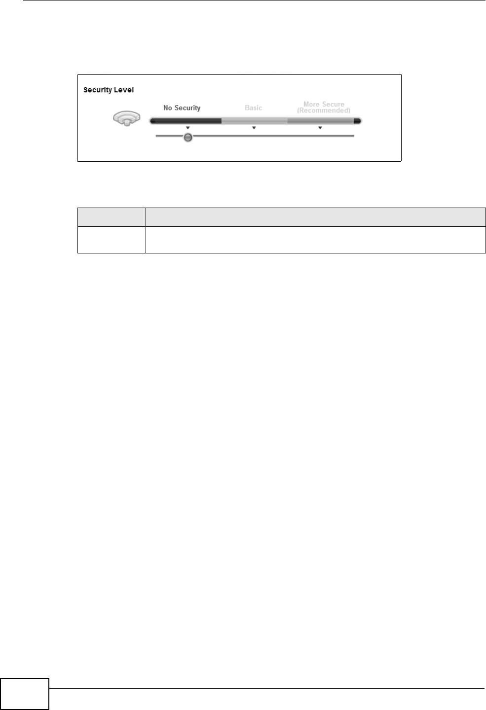
Chapter 6 Wireless
P-2612HNU(L)-FxF User’s Guide
124
Note: If you do not enable any wireless security on your ZyXEL Device, your network
is accessible to any wireless networking device that is within range.
Figure 24 Wireless > General: No Security
The following table describes the labels in this screen.
6.2.2 Basic (Static WEP/Shared WEP Encryption)
WEP encryption scrambles the data transmitted between the wireless stations and
the access points (AP) to keep network communications private. Both the wireless
stations and the access points must use the same WEP key.
There are two types of WEP authentication namely, Open System (Static WEP)
and Shared Key (Shared WEP).
Open system is implemented for ease-of-use and when security is not an issue.
The wireless station and the AP or peer computer do not share a secret key. Thus
the wireless stations can associate with any AP or peer computer and listen to any
transmitted data that is not encrypted.
Shared key mode involves a shared secret key to authenticate the wireless station
to the AP or peer computer. This requires you to enable the wireless LAN security
and use same settings on both the wireless station and the AP or peer computer.
Table 14 Wireless > General: No Security
LABEL DESCRIPTION
Security
Level
Choose No Security from the sliding bar.
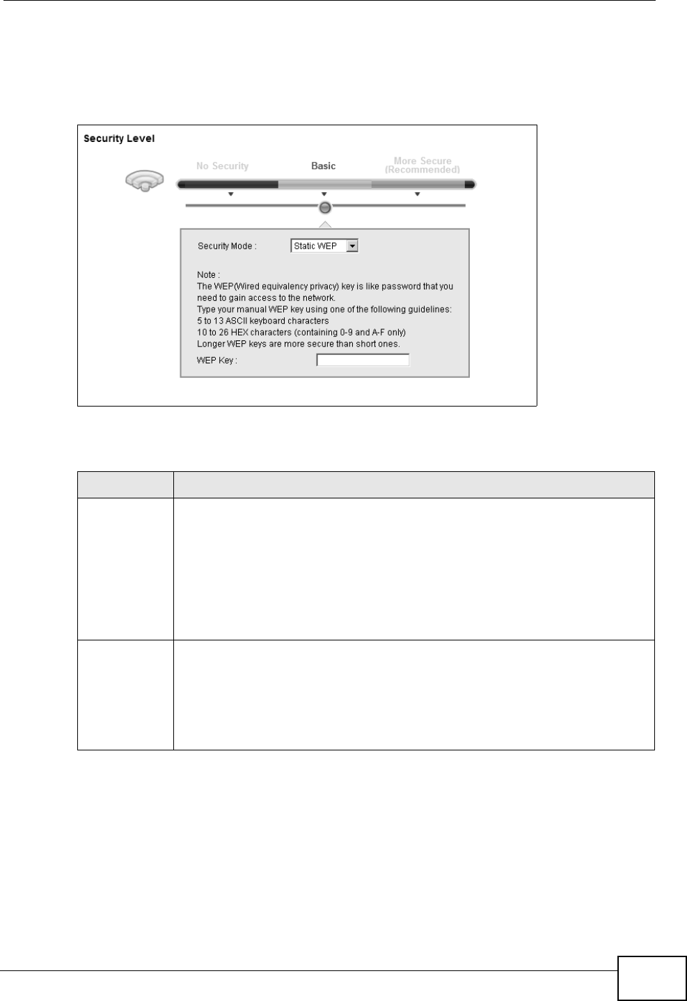
Chapter 6 Wireless
P-2612HNU(L)-FxF User’s Guide 125
In order to configure and enable WEP encryption, click Network Settings >
Wireless to display the General screen. Select Basic as the security level. Then
select Static WEP or Shared WEP from the Security Mode list.
Figure 25 Wireless > General: Basic (Static WEP/Shared WEP)
The following table describes the labels in this screen.
Table 15 Wireless > General: Basic (Static WEP/Shared WEP)
LABEL DESCRIPTION
Security
Mode
Choose Static WEP or Shared WEP from the drop-down list box.
• Select Static WEP to have the ZyXEL Device allow association with
wireless clients that use Open System mode. Data transfer is encrypted
as long as the wireless client has the correct WEP key for encryption.
The ZyXEL Device authenticates wireless clients using Shared Key
mode that have the correct WEP key.
• Select Shared WEP to have the ZyXEL Device authenticate only those
wireless clients that use Shared Key mode and have the correct WEP
key.
WEP Key Enter a WEP key that will be used to encrypt data. Both the ZyXEL Device
and the wireless stations must use the same WEP key for data
transmission.
If you want to manually set the WEP key, enter any 5 or 13 characters
(ASCII string) or 10 or 26 hexadecimal characters ("0-9", "A-F") for a 64-
bit or 128-bit WEP key respectively.

Chapter 6 Wireless
P-2612HNU(L)-FxF User’s Guide
126
6.2.3 More Secure (WPA(2)-PSK)
The WPA-PSK security mode provides both improved data encryption and user
authentication over WEP. Using a Pre-Shared Key (PSK), both the ZyXEL Device
and the connecting client share a common password in order to validate the
connection. This type of encryption, while robust, is not as strong as WPA, WPA2
or even WPA2-PSK. The WPA2-PSK security mode is a newer, more robust version
of the WPA encryption standard. It offers slightly better security, although the use
of PSK makes it less robust than it could be.
Click Network Settings > Wireless to display the General screen. Select More
Secure as the security level. Then select WPA-PSK or WPA2-PSK from the
Security Mode list.
Figure 26 Wireless > General: More Secure: WPA(2)-PSK
The following table describes the labels in this screen.
Table 16 Wireless > General: WPA(2)-PSK
LABEL DESCRIPTION
Security Level Select More Secure to enable WPA(2)-PSK data encryption.
Security Mode Select WPA-PSK or WPA2-PSK from the drop-down list box.
Pre-Shared Key The encryption mechanisms used for WPA/WPA2 and WPA-PSK/
WPA2-PSK are the same. The only difference between the two is that
WPA-PSK/WPA2-PSK uses a simple common password, instead of
user-specific credentials.
Type a pre-shared key from 8 to 63 case-sensitive ASCII characters or
64 hexidecimal digits.
more.../hide
more
Click more... to show more fields in this section. Click hide more to
hide them.

Chapter 6 Wireless
P-2612HNU(L)-FxF User’s Guide 127
6.2.4 WPA(2) Authentication
The WPA2 security mode is currently the most robust form of encryption for
wireless networks. It requires a RADIUS server to authenticate user credentials
and is a full implementation the security protocol. Use this security option for
maximum protection of your network. However, it is the least backwards
compatible with older devices.
The WPA security mode is a security subset of WPA2. It requires the presence of a
RADIUS server on your network in order to validate user credentials. This
encryption standard is slightly older than WPA2 and therefore is more compatible
with older devices.
WPA-PSK
Compatible
This field appears when you choose WPA-PSK2 as the Security Mode.
Check this field to allow wireless devices using WPA-PSK security
mode to connect to your ZyXEL Device. The ZyXEL Device supports
WPA-PSK and WPA2-PSK simultaneously.
Encryption If the security mode is WPA-PSK, the encryption mode is set to TKIP
to enable Temporal Key Integrity Protocol (TKIP) security on your
wireless network.
If the security mode is WPA-PSK2 and WPA-PSK Compatible is
disabled, the encryption mode is set to AES to enable Advanced
Encryption System (AES) security on your wireless network. AES
provides superior security to TKIP.
If the security mode is WPA-PSK2 and WPA-PSK Compatible is
enabled, the encryption mode is set to TKIPAES MIX to allow both
TKIP and AES types of security in your wireless network.
Table 16 Wireless > General: WPA(2)-PSK (continued)
LABEL DESCRIPTION
Chapter 6 Wireless
P-2612HNU(L)-FxF User’s Guide
128
Click Network Settings > Wireless to display the General screen. Select More
Secure as the security level. Then select WPA or WPA2 from the Security Mode
list.
Figure 27 Wireless > General: More Secure: WPA(2)
The following table describes the labels in this screen.
Table 17 Wireless > General: More Secure: WPA(2)
LABEL DESCRIPTION
Security Level Select More Secure to enable WPA(2)-PSK data encryption.
Security Mode Choose WPA or WPA2 from the drop-down list box.
Authentication Server
IP Address Enter the IP address of the external authentication server in dotted
decimal notation.
Port Number Enter the port number of the external authentication server. The
default port number is 1812.
You need not change this value unless your network administrator
instructs you to do so with additional information.
Shared Secret Enter a password (up to 31 alphanumeric characters) as the key to be
shared between the external authentication server and the ZyXEL
Device.
The key must be the same on the external authentication server and
your ZyXEL Device. The key is not sent over the network.
more.../hide
more
Click more... to show more fields in this section. Click hide more to
hide them.
WPA Compatible This field is only available for WPA2. Select this if you want the ZyXEL
Device to support WPA and WPA2 simultaneously.
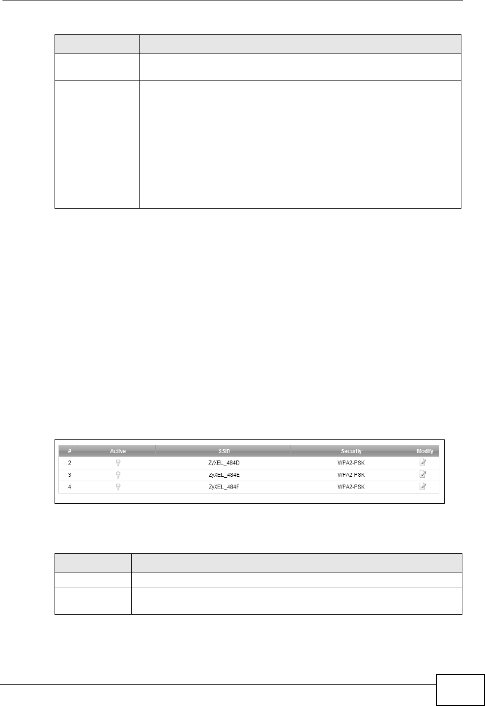
Chapter 6 Wireless
P-2612HNU(L)-FxF User’s Guide 129
6.3 The More AP Screen
The ZyXEL Device can broadcast up to four wireless network names at the same
time. This means that users can connect to the ZyXEL Device using different
SSIDs. You can secure the connection on each SSID profile so that wireless clients
connecting to the ZyXEL Device using different SSIDs cannot communicate with
each other.
This screen allows you to enable and configure multiple Basic Service Sets (BSSs)
on the ZyXEL Device.
Click Network Settings > Wireless > More AP. The following screen displays.
Figure 28 Network Settings > Wireless > More AP
The following table describes the labels in this screen.
Group Key
Update Timer
The Group Key Update Timer is the rate at which the RADIUS server
sends a new group key out to all clients.
Encryption If the security mode is WPA, the encryption mode is set to TKIP to
enable Temporal Key Integrity Protocol (TKIP) security on your
wireless network.
If the security mode is WPA2 and WPA Compatible is disabled, the
encryption mode is set to AES to enable Advanced Encryption System
(AES) security on your wireless network. AES provides superior
security to TKIP.
If the security mode is WPA2 and WPA Compatible is enabled, the
encryption mode is set to TKIPAES MIX to allow the wireless clients
to use either TKIP or AES.
Table 17 Wireless > General: More Secure: WPA(2) (continued)
LABEL DESCRIPTION
Table 18 Network Settings > Wireless > More AP
LABEL DESCRIPTION
# This is the index number of the entry.
Active This field indicates whether this SSID is active. A yellow bulb signifies
that this SSID is active. A gray bulb signifies that this SSID is not active.
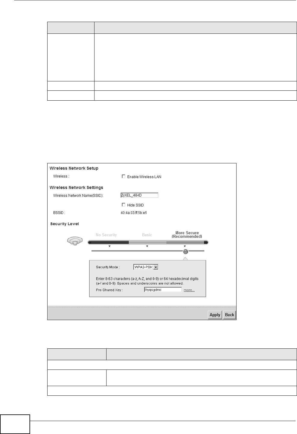
Chapter 6 Wireless
P-2612HNU(L)-FxF User’s Guide
130
6.3.1 Edit More AP
Use this screen to edit an SSID profile. Click the Edit icon next to an SSID in the
More AP screen. The following screen displays.
Figure 29 Wireless > More AP: Edit
The following table describes the fields in this screen.
SSID An SSID profile is the set of parameters relating to one of the ZyXEL
Device’s BSSs. The SSID (Service Set IDentifier) identifies the Service
Set with which a wireless device is associated.
This field displays the name of the wireless profile on the network. When
a wireless client scans for an AP to associate with, this is the name that
is broadcast and seen in the wireless client utility.
Security This field indicates the security mode of the SSID profile.
Modify Click the Edit icon to configure the SSID profile.
Table 18 Network Settings > Wireless > More AP (continued)
LABEL DESCRIPTION
Table 19 Wireless > More AP: Edit
LABEL DESCRIPTION
Wireless Network Setup
Wireless Select the Enable Wireless LAN check box to activate the wireless
LAN.
Wireless Network Settings
Chapter 6 Wireless
P-2612HNU(L)-FxF User’s Guide 131
6.4 The WPS Screen
Use this screen to configure WiFi Protected Setup (WPS) on your ZyXEL Device.
WPS allows you to quickly set up a wireless network with strong security, without
having to configure security settings manually. Set up each WPS connection
between two devices. Both devices must support WPS. See Section 6.7.6.3 on
page 143 for more information about WPS.
Note: The ZyXEL Device applies the security settings of the SSID1 profile (see
Section 6.2 on page 121). If you want to use the WPS feature, make sure you
have set the security mode of SSID1 to WPA-PSK, WPA2-PSK or No Security.
Wireless Network
Name (SSID)
The SSID (Service Set IDentity) identifies the service set with which
a wireless device is associated. Wireless devices associating to the
access point (AP) must have the same SSID.
Enter a descriptive name (up to 32 English keyboard characters) for
the wireless LAN.
Hide SSID Select this check box to hide the SSID in the outgoing beacon frame
so a station cannot obtain the SSID through scanning using a site
survey tool.
BSSID This shows the MAC address of the wireless interface on the ZyXEL
Device when wireless LAN is enabled.
Security Level
Security Mode Select Basic (WEP) or More Secure (WPA(2)-PSK, WPA(2)) to
add security on this wireless network. The wireless clients which
want to associate to this network must have same wireless security
settings as the ZyXEL Device. After you select to use a security,
additional options appears in this screen.
Or you can select No Security to allow any client to associate this
network without any data encryption or authentication.
See Section 6.2.1 on page 123 for more details about this field.
Apply Click Apply to save your changes.
Back Click Back to exit this screen without saving.
Table 19 Wireless > More AP: Edit (continued)
LABEL DESCRIPTION
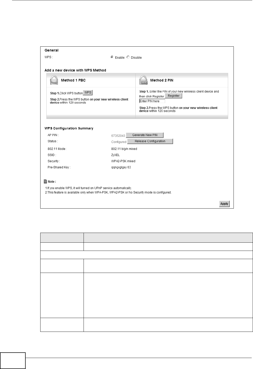
Chapter 6 Wireless
P-2612HNU(L)-FxF User’s Guide
132
Click Network Setting > Wireless > WPS. The following screen displays. Select
Enable and click Apply to activate the WPS function. You can configure the WPS
settings in this screen.
Figure 30 Network Setting > Wireless > WPS
The following table describes the labels in this screen.
Table 20 Network Setting > Wireless > WPS
LABEL DESCRIPTION
Enable WPS Select Enable to activate WPS on the ZyXEL Device.
Add a new device with WPS Method
Method 1PBC Use this section to set up a WPS wireless network using Push Button
Configuration (PBC).
WPS Click this button to add another WPS-enabled wireless device (within
wireless range of the ZyXEL Device) to your wireless network. This
button may either be a physical button on the outside of device, or a
menu button similar to the WPS button on this screen.
Note: You must press the other wireless device’s WPS button
within two minutes of pressing this button.
Method 2 PIN Use this section to set up a WPS wireless network by entering the PIN
(Personal Identification Number) of the client into the ZyXEL Device.

Chapter 6 Wireless
P-2612HNU(L)-FxF User’s Guide 133
6.5 The WMM Screen
Use this screen to enable or disable Wi-Fi MultiMedia (WMM) wireless networks for
multimedia applications.
Register Enter the PIN of the device that you are setting up a WPS connection
with and click Register to authenticate and add the wireless device to
your wireless network.
You can find the PIN either on the outside of the device, or by checking
the device’s settings.
Note: You must also activate WPS on that device within two
minutes to have it present its PIN to the ZyXEL Device.
WPS Configuration Summary
AP PIN The PIN of the ZyXEL Device is shown here. Enter this PIN in the
configuration utility of the device you want to connect to using WPS.
The PIN is not necessary when you use WPS push-button method.
Click the Generate New PIN button to have the ZyXEL Device create
a new PIN.
Status This displays Configured when the ZyXEL Device has connected to a
wireless network using WPS or Enable WPS is selected and wireless or
wireless security settings have been changed. The current wireless and
wireless security settings also appear in the screen.
This displays Not Configured when there is no wireless or wireless
security changes on the ZyXEL Device or you click Release
Configuration to remove the configured wireless and wireless security
settings.
Release
Configuration This button is available when the WPS status is Configured.
Click this button to remove all configured wireless and wireless security
settings for WPS connections on the ZyXEL Device.
802.11 Mode This is the 802.11 mode used. Only compliant WLAN devices can
associate with the ZyXEL Device.
SSID This is the name of the wireless network.
Security This is the type of wireless security employed by the network.
Apply Click Apply to save your changes.
Table 20 Network Setting > Wireless > WPS (continued)
LABEL DESCRIPTION
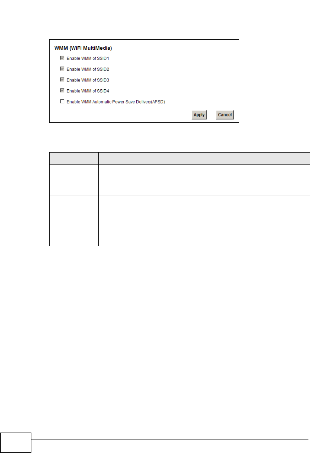
Chapter 6 Wireless
P-2612HNU(L)-FxF User’s Guide
134
Click Network Setting > Wireless > WMM. The following screen displays.
Figure 31 Network Setting > Wireless > WMM
The following table describes the labels in this screen.
Table 21 Network Setting > Wireless > WMM
LABEL DESCRIPTION
Enable WMM of
SSID1~4
This enables the ZyXEL Device to automatically give a service a priority
level according to the ToS value in the IP header of packets it sends.
WMM QoS (Wifi MultiMedia Quality of Service) gives high priority to voice
and video, which makes them run more smoothly.
Enable WMM
Automatic
Power Save
Deliver (APSD)
Click this to increase battery life for battery-powered wireless clients.
APSD uses a longer beacon interval when transmitting traffic that does
not require a short packet exchange interval.
Apply Click Apply to save your changes.
Cancel Click Cancel to restore your previously saved settings.
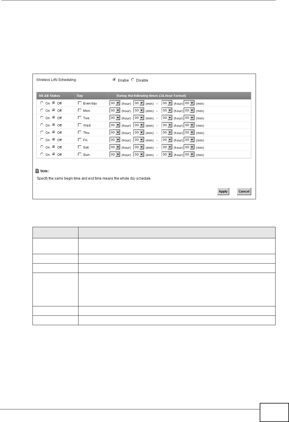
Chapter 6 Wireless
P-2612HNU(L)-FxF User’s Guide 135
6.6 Scheduling Screen
Click Network Setting > Wireless > Scheduling to open the Wireless LAN
Scheduling screen. Use this screen to configure when the ZyXEL Device enables
or disables the wireless LAN.
Figure 32 Network Setting > Wireless > Scheduling
The following table describes the labels in this screen.
6.7 Technical Reference
This section discusses wireless LANs in depth. For more information, see the
appendix.
Table 22 Network Setting > Wireless > Scheduling
LABEL DESCRIPTION
Wireless LAN
Scheduling
Select Enable to activate wireless LAN scheduling on your ZyXEL
Device.
WLAN status Select On or Off to enable or disable the wireless LAN.
Day Select the day(s) you want to turn the wireless LAN on or off.
During the
following times
Specify the time period during which to apply the schedule.
For example, you want the wireless network to be only available during
work hours. Check Mon ~ Fri in the day column, and specify 8:00 ~
18:00 in the time table.
Apply Click Apply to save your changes.
Cancel Click Cancel to restore your previously saved settings.
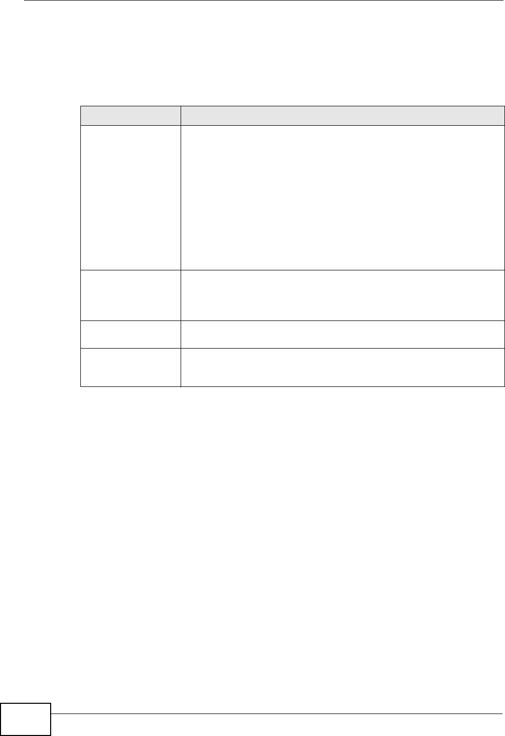
Chapter 6 Wireless
P-2612HNU(L)-FxF User’s Guide
136
6.7.1 Additional Wireless Terms
The following table describes some wireless network terms and acronyms used in
the ZyXEL Device’s web configurator.
6.7.2 Wireless Security Overview
By their nature, radio communications are simple to intercept. For wireless data
networks, this means that anyone within range of a wireless network without
security can not only read the data passing over the airwaves, but also join the
network. Once an unauthorized person has access to the network, he or she can
steal information or introduce malware (malicious software) intended to
compromise the network. For these reasons, a variety of security systems have
been developed to ensure that only authorized people can use a wireless data
network, or understand the data carried on it.
These security standards do two things. First, they authenticate. This means that
only people presenting the right credentials (often a username and password, or a
“key” phrase) can access the network. Second, they encrypt. This means that the
information sent over the air is encoded. Only people with the code key can
understand the information, and only people who have been authenticated are
given the code key.
Table 23 Additional Wireless Terms
TERM DESCRIPTION
RTS/CTS Threshold In a wireless network which covers a large area, wireless devices
are sometimes not aware of each other’s presence. This may cause
them to send information to the AP at the same time and result in
information colliding and not getting through.
By setting this value lower than the default value, the wireless
devices must sometimes get permission to send information to the
ZyXEL Device. The lower the value, the more often the devices must
get permission.
If this value is greater than the fragmentation threshold value (see
below), then wireless devices never have to get permission to send
information to the ZyXEL Device.
Preamble A preamble affects the timing in your wireless network. There are
two preamble modes: long and short. If a device uses a different
preamble mode than the ZyXEL Device does, it cannot communicate
with the ZyXEL Device.
Authentication The process of verifying whether a wireless device is allowed to use
the wireless network.
Fragmentation
Threshold
A small fragmentation threshold is recommended for busy networks,
while a larger threshold provides faster performance if the network
is not very busy.

Chapter 6 Wireless
P-2612HNU(L)-FxF User’s Guide 137
These security standards vary in effectiveness. Some can be broken, such as the
old Wired Equivalent Protocol (WEP). Using WEP is better than using no security at
all, but it will not keep a determined attacker out. Other security standards are
secure in themselves but can be broken if a user does not use them properly. For
example, the WPA-PSK security standard is very secure if you use a long key
which is difficult for an attacker’s software to guess - for example, a twenty-letter
long string of apparently random numbers and letters - but it is not very secure if
you use a short key which is very easy to guess - for example, a three-letter word
from the dictionary.
Because of the damage that can be done by a malicious attacker, it’s not just
people who have sensitive information on their network who should use security.
Everybody who uses any wireless network should ensure that effective security is
in place.
A good way to come up with effective security keys, passwords and so on is to use
obscure information that you personally will easily remember, and to enter it in a
way that appears random and does not include real words. For example, if your
mother owns a 1970 Dodge Challenger and her favorite movie is Vanishing Point
(which you know was made in 1971) you could use “70dodchal71vanpoi” as your
security key.
The following sections introduce different types of wireless security you can set up
in the wireless network.
6.7.2.1 SSID
Normally, the ZyXEL Device acts like a beacon and regularly broadcasts the SSID
in the area. You can hide the SSID instead, in which case the ZyXEL Device does
not broadcast the SSID. In addition, you should change the default SSID to
something that is difficult to guess.
This type of security is fairly weak, however, because there are ways for
unauthorized wireless devices to get the SSID. In addition, unauthorized wireless
devices can still see the information that is sent in the wireless network.
6.7.2.2 MAC Address Filter
Every device that can use a wireless network has a unique identification number,
called a MAC address.1A MAC address is usually written using twelve hexadecimal
characters2; for example, 00A0C5000002 or 00:A0:C5:00:00:02. To get the MAC
address for each device in the wireless network, see the device’s User’s Guide or
other documentation.
1. Some wireless devices, such as scanners, can detect wireless networks but cannot use wireless networks.
These kinds of wireless devices might not have MAC addresses.
2. Hexadecimal characters are 0, 1, 2, 3, 4, 5, 6, 7, 8, 9, A, B, C, D, E, and F.

Chapter 6 Wireless
P-2612HNU(L)-FxF User’s Guide
138
You can use the MAC address filter to tell the ZyXEL Device which devices are
allowed or not allowed to use the wireless network. If a device is allowed to use
the wireless network, it still has to have the correct information (SSID, channel,
and security). If a device is not allowed to use the wireless network, it does not
matter if it has the correct information.
This type of security does not protect the information that is sent in the wireless
network. Furthermore, there are ways for unauthorized wireless devices to get the
MAC address of an authorized device. Then, they can use that MAC address to use
the wireless network.
6.7.2.3 User Authentication
Authentication is the process of verifying whether a wireless device is allowed to
use the wireless network. You can make every user log in to the wireless network
before using it. However, every device in the wireless network has to support IEEE
802.1x to do this.
For wireless networks, you can store the user names and passwords for each user
in a RADIUS server. This is a server used in businesses more than in homes. If you
do not have a RADIUS server, you cannot set up user names and passwords for
your users.
Unauthorized wireless devices can still see the information that is sent in the
wireless network, even if they cannot use the wireless network. Furthermore,
there are ways for unauthorized wireless users to get a valid user name and
password. Then, they can use that user name and password to use the wireless
network.
6.7.2.4 Encryption
Wireless networks can use encryption to protect the information that is sent in the
wireless network. Encryption is like a secret code. If you do not know the secret
code, you cannot understand the message.
The types of encryption you can choose depend on the type of authentication.
(See Section 6.7.2.3 on page 138 for information about this.)
Table 24 Types of Encryption for Each Type of Authentication
NO AUTHENTICATION RADIUS SERVER
Weakest No Security WPA
Static WEP
WPA-PSK
Strongest WPA2-PSK WPA2

Chapter 6 Wireless
P-2612HNU(L)-FxF User’s Guide 139
For example, if the wireless network has a RADIUS server, you can choose WPA
or WPA2. If users do not log in to the wireless network, you can choose no
encryption, Static WEP, WPA-PSK, or WPA2-PSK.
Usually, you should set up the strongest encryption that every device in the
wireless network supports. For example, suppose you have a wireless network
with the ZyXEL Device and you do not have a RADIUS server. Therefore, there is
no authentication. Suppose the wireless network has two devices. Device A only
supports WEP, and device B supports WEP and WPA. Therefore, you should set up
Static WEP in the wireless network.
Note: It is recommended that wireless networks use WPA-PSK, WPA, or stronger
encryption. The other types of encryption are better than none at all, but it is still
possible for unauthorized wireless devices to figure out the original information
pretty quickly.
When you select WPA2 or WPA2-PSK in your ZyXEL Device, you can also select
an option (WPA compatible) to support WPA as well. In this case, if some of the
devices support WPA and some support WPA2, you should set up WPA2-PSK or
WPA2 (depending on the type of wireless network login) and select the WPA
compatible option in the ZyXEL Device.
Many types of encryption use a key to protect the information in the wireless
network. The longer the key, the stronger the encryption. Every device in the
wireless network must have the same key.
6.7.3 Signal Problems
Because wireless networks are radio networks, their signals are subject to
limitations of distance, interference and absorption.
Problems with distance occur when the two radios are too far apart. Problems with
interference occur when other radio waves interrupt the data signal. Interference
may come from other radio transmissions, such as military or air traffic control
communications, or from machines that are coincidental emitters such as electric
motors or microwaves. Problems with absorption occur when physical objects
(such as thick walls) are between the two radios, muffling the signal.
6.7.4 BSS
A Basic Service Set (BSS) exists when all communications between wireless
stations or between a wireless station and a wired network client go through one
access point (AP).
Intra-BSS traffic is traffic between wireless stations in the BSS. When Intra-BSS
traffic blocking is disabled, wireless station A and B can access the wired network
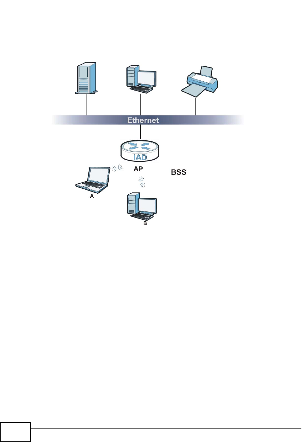
Chapter 6 Wireless
P-2612HNU(L)-FxF User’s Guide
140
and communicate with each other. When Intra-BSS traffic blocking is enabled,
wireless station A and B can still access the wired network but cannot
communicate with each other.
Figure 33 Basic Service set
6.7.5 MBSSID
Traditionally, you need to use different APs to configure different Basic Service
Sets (BSSs). As well as the cost of buying extra APs, there is also the possibility of
channel interference. The ZyXEL Device’s MBSSID (Multiple Basic Service Set
IDentifier) function allows you to use one access point to provide several BSSs
simultaneously. You can then assign varying QoS priorities and/or security modes
to different SSIDs.
Wireless devices can use different BSSIDs to associate with the same AP.
6.7.5.1 Notes on Multiple BSSs
• A maximum of eight BSSs are allowed on one AP simultaneously.
• You must use different keys for different BSSs. If two wireless devices have
different BSSIDs (they are in different BSSs), but have the same keys, they
may hear each other’s communications (but not communicate with each other).
• MBSSID should not replace but rather be used in conjunction with 802.1x
security.

Chapter 6 Wireless
P-2612HNU(L)-FxF User’s Guide 141
6.7.6 WiFi Protected Setup (WPS)
Your ZyXEL Device supports WiFi Protected Setup (WPS), which is an easy way to
set up a secure wireless network. WPS is an industry standard specification,
defined by the WiFi Alliance.
WPS allows you to quickly set up a wireless network with strong security, without
having to configure security settings manually. Each WPS connection works
between two devices. Both devices must support WPS (check each device’s
documentation to make sure).
Depending on the devices you have, you can either press a button (on the device
itself, or in its configuration utility) or enter a PIN (a unique Personal Identification
Number that allows one device to authenticate the other) in each of the two
devices. When WPS is activated on a device, it has two minutes to find another
device that also has WPS activated. Then, the two devices connect and set up a
secure network by themselves.
6.7.6.1 Push Button Configuration
WPS Push Button Configuration (PBC) is initiated by pressing a button on each
WPS-enabled device, and allowing them to connect automatically. You do not need
to enter any information.
Not every WPS-enabled device has a physical WPS button. Some may have a WPS
PBC button in their configuration utilities instead of or in addition to the physical
button.
Take the following steps to set up WPS using the button.
1Ensure that the two devices you want to set up are within wireless range of one
another.
2Look for a WPS button on each device. If the device does not have one, log into its
configuration utility and locate the button (see the device’s User’s Guide for how to
do this - for the ZyXEL Device, see Section 6.4 on page 131).
3Press the button on one of the devices (it doesn’t matter which). For the ZyXEL
Device you must press the WPS button for more than three seconds.
4Within two minutes, press the button on the other device. The registrar sends the
network name (SSID) and security key through an secure connection to the
enrollee.
If you need to make sure that WPS worked, check the list of associated wireless
clients in the AP’s configuration utility. If you see the wireless client in the list,
WPS was successful.

Chapter 6 Wireless
P-2612HNU(L)-FxF User’s Guide
142
6.7.6.2 PIN Configuration
Each WPS-enabled device has its own PIN (Personal Identification Number). This
may either be static (it cannot be changed) or dynamic (in some devices you can
generate a new PIN by clicking on a button in the configuration interface).
Use the PIN method instead of the push-button configuration (PBC) method if you
want to ensure that the connection is established between the devices you specify,
not just the first two devices to activate WPS in range of each other. However, you
need to log into the configuration interfaces of both devices to use the PIN
method.
When you use the PIN method, you must enter the PIN from one device (usually
the wireless client) into the second device (usually the Access Point or wireless
router). Then, when WPS is activated on the first device, it presents its PIN to the
second device. If the PIN matches, one device sends the network and security
information to the other, allowing it to join the network.
Take the following steps to set up a WPS connection between an access point or
wireless router (referred to here as the AP) and a client device using the PIN
method.
1Ensure WPS is enabled on both devices.
2Access the WPS section of the AP’s configuration interface. See the device’s User’s
Guide for how to do this.
3Look for the client’s WPS PIN; it will be displayed either on the device, or in the
WPS section of the client’s configuration interface (see the device’s User’s Guide
for how to find the WPS PIN - for the ZyXEL Device, see Section 6.4 on page 131).
4Enter the client’s PIN in the AP’s configuration interface.
5If the client device’s configuration interface has an area for entering another
device’s PIN, you can either enter the client’s PIN in the AP, or enter the AP’s PIN
in the client - it does not matter which.
6Start WPS on both devices within two minutes.
7Use the configuration utility to activate WPS, not the push-button on the device
itself.
8On a computer connected to the wireless client, try to connect to the Internet. If
you can connect, WPS was successful.
If you cannot connect, check the list of associated wireless clients in the AP’s
configuration utility. If you see the wireless client in the list, WPS was successful.
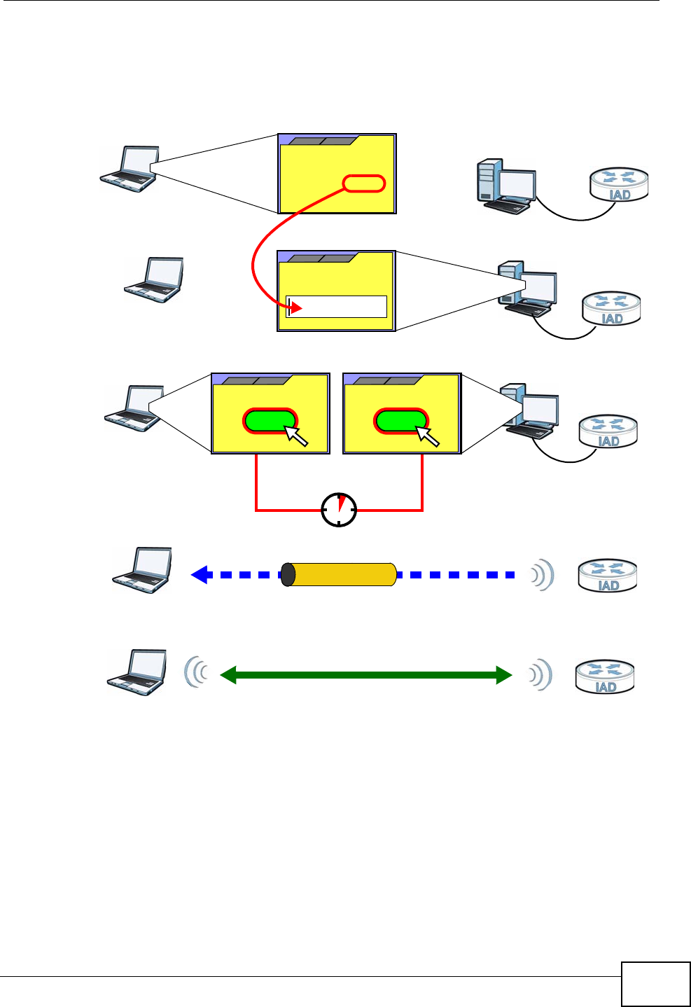
Chapter 6 Wireless
P-2612HNU(L)-FxF User’s Guide 143
The following figure shows a WPS-enabled wireless client (installed in a notebook
computer) connecting to the WPS-enabled AP via the PIN method.
Figure 34 Example WPS Process: PIN Method
6.7.6.3 How WPS Works
When two WPS-enabled devices connect, each device must assume a specific role.
One device acts as the registrar (the device that supplies network and security
settings) and the other device acts as the enrollee (the device that receives
network and security settings. The registrar creates a secure EAP (Extensible
Authentication Protocol) tunnel and sends the network name (SSID) and the WPA-
PSK or WPA2-PSK pre-shared key to the enrollee. Whether WPA-PSK or WPA2-PSK
is used depends on the standards supported by the devices. If the registrar is
already part of a network, it sends the existing information. If not, it generates
the SSID and WPA(2)-PSK randomly.
ENROLLEE
SECURE EAP TUNNEL
SSID
WPA(2)-PSK
WITHIN 2 MINUTES
COMMUNICATION
This device’s
WPS
Enter WPS PIN
WPS
from other device:
WPS PIN: 123456
WPS
START
WPS
START
REGISTRAR
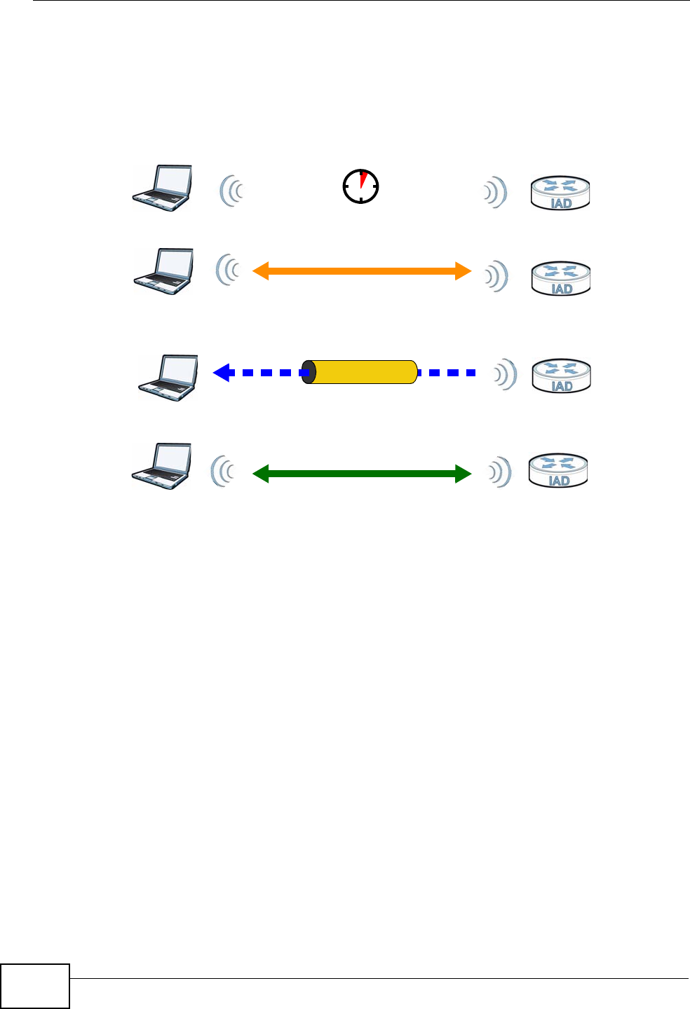
Chapter 6 Wireless
P-2612HNU(L)-FxF User’s Guide
144
The following figure shows a WPS-enabled client (installed in a notebook
computer) connecting to a WPS-enabled access point.
Figure 35 How WPS works
The roles of registrar and enrollee last only as long as the WPS setup process is
active (two minutes). The next time you use WPS, a different device can be the
registrar if necessary.
The WPS connection process is like a handshake; only two devices participate in
each WPS transaction. If you want to add more devices you should repeat the
process with one of the existing networked devices and the new device.
Note that the access point (AP) is not always the registrar, and the wireless client
is not always the enrollee. All WPS-certified APs can be a registrar, and so can
some WPS-enabled wireless clients.
By default, a WPS devices is “unconfigured”. This means that it is not part of an
existing network and can act as either enrollee or registrar (if it supports both
functions). If the registrar is unconfigured, the security settings it transmits to the
enrollee are randomly-generated. Once a WPS-enabled device has connected to
another device using WPS, it becomes “configured”. A configured wireless client
can still act as enrollee or registrar in subsequent WPS connections, but a
configured access point can no longer act as enrollee. It will be the registrar in all
subsequent WPS connections in which it is involved. If you want a configured AP to
act as an enrollee, you must reset it to its factory defaults.
SECURE TUNNEL
SECURITY INFO
WITHIN 2 MINUTES
COMMUNICATION
ACTIVATE
WPS
ACTIVATE
WPS
WPS HANDSHAKE
REGISTRARENROLLEE
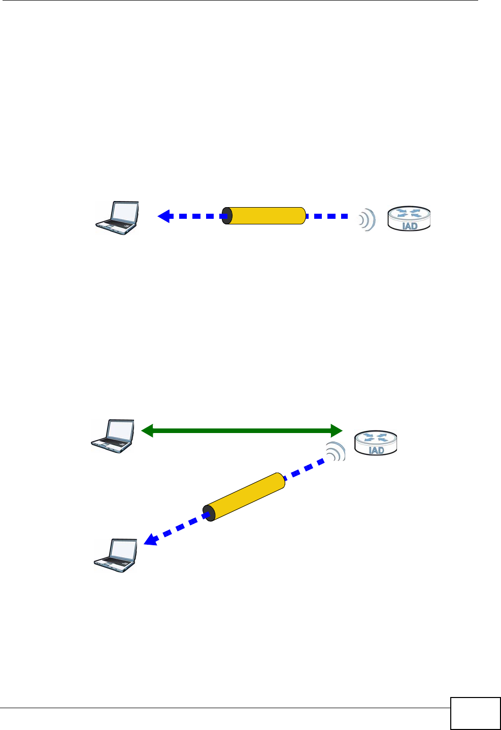
Chapter 6 Wireless
P-2612HNU(L)-FxF User’s Guide 145
6.7.6.4 Example WPS Network Setup
This section shows how security settings are distributed in an example WPS setup.
The following figure shows an example network. In step 1, both AP1 and Client 1
are unconfigured. When WPS is activated on both, they perform the handshake. In
this example, AP1 is the registrar, and Client 1 is the enrollee. The registrar
randomly generates the security information to set up the network, since it is
unconfigured and has no existing information.
Figure 36 WPS: Example Network Step 1
In step 2, you add another wireless client to the network. You know that Client 1
supports registrar mode, but it is better to use AP1 for the WPS handshake with
the new client since you must connect to the access point anyway in order to use
the network. In this case, AP1 must be the registrar, since it is configured (it
already has security information for the network). AP1 supplies the existing
security information to Client 2.
Figure 37 WPS: Example Network Step 2
REGISTRARENROLLEE
SECURITY INFO
CLIENT 1 AP1
REGISTRAR
CLIENT 1 AP1
ENROLLEE
CLIENT 2
EXISTING CONNECTION
SECURITYINFO
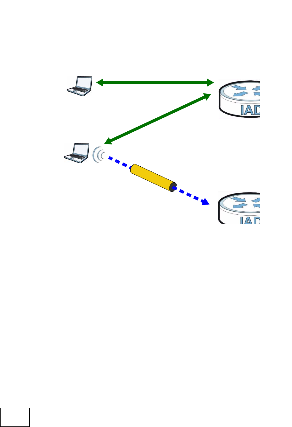
Chapter 6 Wireless
P-2612HNU(L)-FxF User’s Guide
146
In step 3, you add another access point (AP2) to your network. AP2 is out of
range of AP1, so you cannot use AP1 for the WPS handshake with the new access
point. However, you know that Client 2 supports the registrar function, so you use
it to perform the WPS handshake instead.
Figure 38 WPS: Example Network Step 3
6.7.6.5 Limitations of WPS
WPS has some limitations of which you should be aware.
• WPS works in Infrastructure networks only (where an AP and a wireless client
communicate). It does not work in Ad-Hoc networks (where there is no AP).
• When you use WPS, it works between two devices only. You cannot enroll
multiple devices simultaneously, you must enroll one after the other.
For instance, if you have two enrollees and one registrar you must set up the
first enrollee (by pressing the WPS button on the registrar and the first enrollee,
for example), then check that it successfully enrolled, then set up the second
device in the same way.
• WPS works only with other WPS-enabled devices. However, you can still add
non-WPS devices to a network you already set up using WPS.
WPS works by automatically issuing a randomly-generated WPA-PSK or WPA2-
PSK pre-shared key from the registrar device to the enrollee devices. Whether
the network uses WPA-PSK or WPA2-PSK depends on the device. You can check
the configuration interface of the registrar device to discover the key the
network is using (if the device supports this feature). Then, you can enter the
key into the non-WPS device and join the network as normal (the non-WPS
device must also support WPA-PSK or WPA2-PSK).
CLIENT 1 AP1
REGISTRAR
CLIENT 2
EXISTING CONNECTION
SECURITYINFO
ENROLLEE
AP2
EXISTINGCONNECTION

Chapter 6 Wireless
P-2612HNU(L)-FxF User’s Guide 147
• When you use the PBC method, there is a short period (from the moment you
press the button on one device to the moment you press the button on the
other device) when any WPS-enabled device could join the network. This is
because the registrar has no way of identifying the “correct” enrollee, and
cannot differentiate between your enrollee and a rogue device. This is a possible
way for a hacker to gain access to a network.
You can easily check to see if this has happened. WPS works between only two
devices simultaneously, so if another device has enrolled your device will be
unable to enroll, and will not have access to the network. If this happens, open
the access point’s configuration interface and look at the list of associated
clients (usually displayed by MAC address). It does not matter if the access
point is the WPS registrar, the enrollee, or was not involved in the WPS
handshake; a rogue device must still associate with the access point to gain
access to the network. Check the MAC addresses of your wireless clients
(usually printed on a label on the bottom of the device). If there is an unknown
MAC address you can remove it or reset the AP.

Chapter 6 Wireless
P-2612HNU(L)-FxF User’s Guide
148
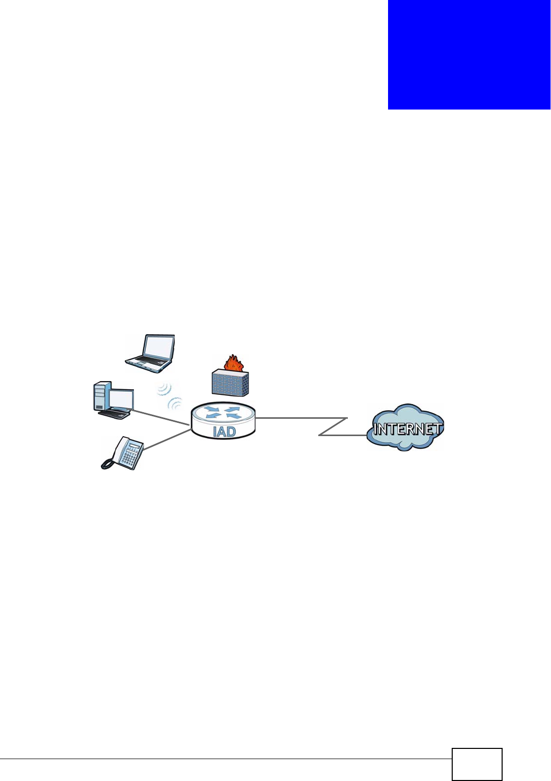
P-2612HNU(L)-FxF User’s Guide 149
CHAPTER 7
Home Networking
7.1 Overview
A Local Area Network (LAN) is a shared communication system to which many
computers are attached. A LAN is usually located in one immediate area such as a
building or floor of a building.
The LAN screens can help you configure a LAN DHCP server and manage IP
addresses.
7.1.1 What You Can Do in this Chapter
• Use the LAN IP screen to set the LAN IP address, subnet mask, and DHCP
settings (Section 7.2 on page 153).
• Use the DHCP Server screen to configure the DNS server information that the
ZyXEL Device sends to the DHCP client devices on the LAN (Section 7.3 on page
154).
• Use the UPnP screen to enable UPnP (Section 7.4 on page 156).
• Use the File Sharing screen to enable file-sharing server (Section 7.5 on page
157).
• Use the Printer Server screen to enable the print server (Section 7.6 on page
160).
DSL
LAN

Chapter 7 Home Networking
P-2612HNU(L)-FxF User’s Guide
150
7.1.2 What You Need To Know
The following terms and concepts may help as you read this chapter.
7.1.2.1 About LAN
IP Address
Similar to the way houses on a street share a common street name, so too do
computers on a LAN share one common network number. This is known as an
Internet Protocol address.
Subnet Mask
The subnet mask specifies the network number portion of an IP address. Your
ZyXEL Device will compute the subnet mask automatically based on the IP
address that you entered. You don't need to change the subnet mask computed by
the ZyXEL Device unless you are instructed to do otherwise.
DHCP
DHCP (Dynamic Host Configuration Protocol) allows clients to obtain TCP/IP
configuration at start-up from a server. This ZyXEL Device has a built-in DHCP
server capability that assigns IP addresses and DNS servers to systems that
support DHCP client capability.
DNS
DNS (Domain Name System) maps a domain name to its corresponding IP
address and vice versa. The DNS server is extremely important because without
it, you must know the IP address of a computer before you can access it. The DNS
server addresses you enter when you set up DHCP are passed to the client
machines along with the assigned IP address and subnet mask.
7.1.2.2 About UPnP
How do I know if I'm using UPnP?
UPnP hardware is identified as an icon in the Network Connections folder
(Windows XP). Each UPnP compatible device installed on your network will appear
as a separate icon. Selecting the icon of a UPnP device will allow you to access the
information and properties of that device.

Chapter 7 Home Networking
P-2612HNU(L)-FxF User’s Guide 151
Cautions with UPnP
The automated nature of NAT traversal applications in establishing their own
services and opening firewall ports may present network security issues. Network
information and configuration may also be obtained and modified by users in some
network environments.
When a UPnP device joins a network, it announces its presence with a multicast
message. For security reasons, the ZyXEL Device allows multicast messages on
the LAN only.
All UPnP-enabled devices may communicate freely with each other without
additional configuration. Disable UPnP if this is not your intention.
UPnP and ZyXEL
ZyXEL has achieved UPnP certification from the Universal Plug and Play Forum
UPnP™ Implementers Corp. (UIC). ZyXEL's UPnP implementation supports
Internet Gateway Device (IGD) 1.0.
See Section 7.8 on page 165 for examples of installing and using UPnP.
7.1.2.3 About File Sharing
User Account
This gives you access to the file sharing server. It includes your user name and
password.
Workgroup name
This is the name given to a set of computers that are connected on a network and
share resources such as a printer or files. Windows automatically assigns the
workgroup name when you set up a network.
Shares
When settings are set to default, each USB device connected to the ZyXEL Device
is given a folder, called a “share”. If a USB hard drive connected to the ZyXEL
Device has more than one partition, then each partition will be allocated a share.
You can also configure a “share” to be a sub-folder or file on the USB device.
File Systems
A file system is a way of storing and organizing files on your hard drive and
storage device. Often different operating systems such as Windows or Linux have

Chapter 7 Home Networking
P-2612HNU(L)-FxF User’s Guide
152
different file systems. The file sharing feature on your ZyXEL Device supports File
Allocation Table (FAT), FAT32, and New Technology File System (NTFS).
Common Internet File System
The ZyXEL Device uses Common Internet File System (CIFS) protocol for its file
sharing functions. CIFS compatible computers can access the USB file storage
devices connected to the ZyXEL Device. CIFS protocol is supported on Microsoft
Windows, Linux Samba and other operating systems (refer to your systems
specifications for CIFS compatibility).
7.1.2.4 About Printer Server
Print Server
This is a computer or other device which manages one or more printers, and
which sends print jobs to each printer from the computer itself or other devices.
Operating System
An operating system (OS) is the interface which helps you manage a computer.
Common examples are Microsoft Windows, Mac OS or Linux.
TCP/IP
TCP/IP (Transmission Control Protocol/ Internet Protocol) is a set of
communications protocols that most of the Internet runs on.
Port
A port maps a network service such as http to a process running on your
computer, such as a process run by your web browser. When traffic from the
Internet is received on your computer, the port number is used to identify which
process running on your computer it is intended for.
Supported OSs
Your operating system must support TCP/IP ports for printing and be compatible
with the RAW protocol.
The following OSs support ZyXEL Device’s printer sharing feature.
• Microsoft Windows 95, Windows 98 SE (Second Edition), Windows Me, Windows
NT 4.0, Windows 2000, Windows XP or Macintosh OS X.
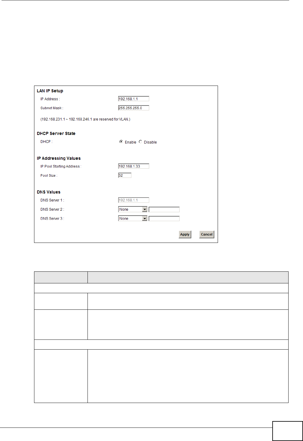
Chapter 7 Home Networking
P-2612HNU(L)-FxF User’s Guide 153
7.2 The LAN Setup Screen
Click Network Setting > Home Networking to open the LAN Setup screen.
Use this screen to set the Local Area Network IP address and subnet mask of your
ZyXEL Device and configure the DNS server information that the ZyXEL Device
sends to the DHCP client devices on the LAN.
Figure 39 Network Setting > Home Networking > LAN Setup
The following table describes the fields in this screen.
Table 25 Network Setting > Home Networking > LAN Setup
LABEL DESCRIPTION
LAN IP Setup
IP Address Enter the LAN IP address you want to assign to your ZyXEL Device in
dotted decimal notation, for example, 192.168.1.1 (factory default).
IP Subnet Mask Type the subnet mask of your network in dotted decimal notation, for
example 255.255.255.0 (factory default). Your ZyXEL Device
automatically computes the subnet mask based on the IP address you
enter, so do not change this field unless you are instructed to do so.
DHCP Server State
DHCP Select Enable to have your ZyXEL Device assign IP addresses, an IP
default gateway and DNS servers to LAN computers and other devices
that are DHCP clients.
If you select Disable, you need to manually configure the IP
addresses of the computers and other devices on your LAN.
When DHCP is used, the following fields need to be set.
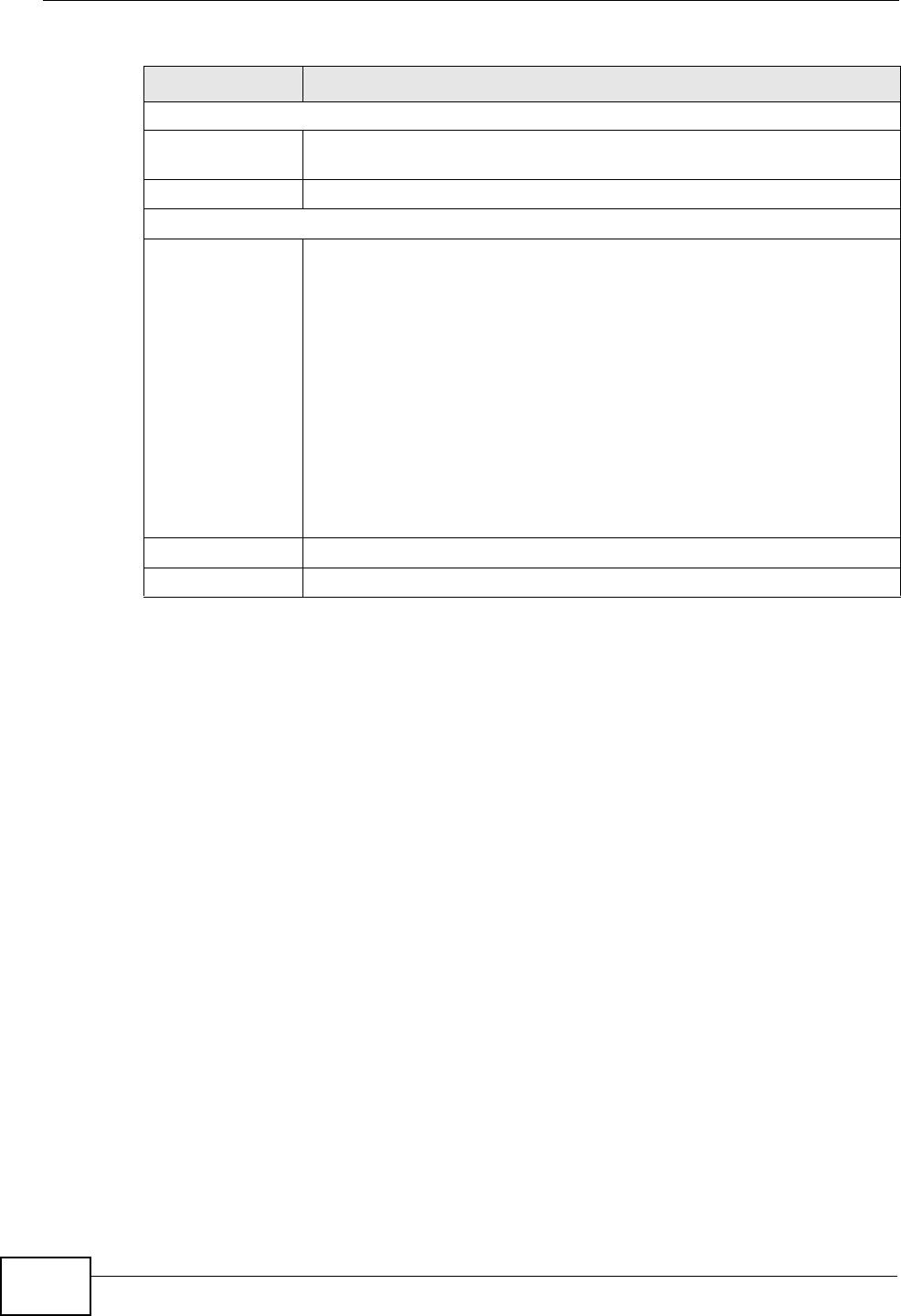
Chapter 7 Home Networking
P-2612HNU(L)-FxF User’s Guide
154
7.3 The Static DHCP Screen
This table allows you to assign IP addresses on the LAN to specific individual
computers based on their MAC Addresses.
Every Ethernet device has a unique MAC (Media Access Control) address. The MAC
address is assigned at the factory and consists of six pairs of hexadecimal
characters, for example, 00:A0:C5:00:00:02.
7.3.1 Before You Begin
Find out the MAC addresses of your network devices if you intend to add them to
the Static DHCP screen.
IP Addressing Values
IP Pool Starting
Address
This field specifies the first of the contiguous addresses in the IP
address pool.
Pool Size This field specifies the size, or count of the IP address pool.
DNS Values
DNS Server 1-3 Select From ISP if your ISP dynamically assigns DNS server
information (and the ZyXEL Device's WAN IP address).
Select User-Defined if you have the IP address of a DNS server. Enter
the DNS server's IP address in the field to the right. If you chose
User-Defined, but leave the IP address set to 0.0.0.0, User-Defined
changes to None after you click Apply. If you set a second choice to
User-Defined, and enter the same IP address, the second User-
Defined changes to None after you click Apply.
Select None if you do not want to configure DNS servers. You must
have another DHCP sever on your LAN, or else the computers must
have their DNS server addresses manually configured. If you do not
configure a DNS server, you must know the IP address of a computer
in order to access it.
Apply Click Apply to save your changes.
Cancel Click Cancel to restore your previously saved settings.
Table 25 Network Setting > Home Networking > LAN Setup (continued)
LABEL DESCRIPTION
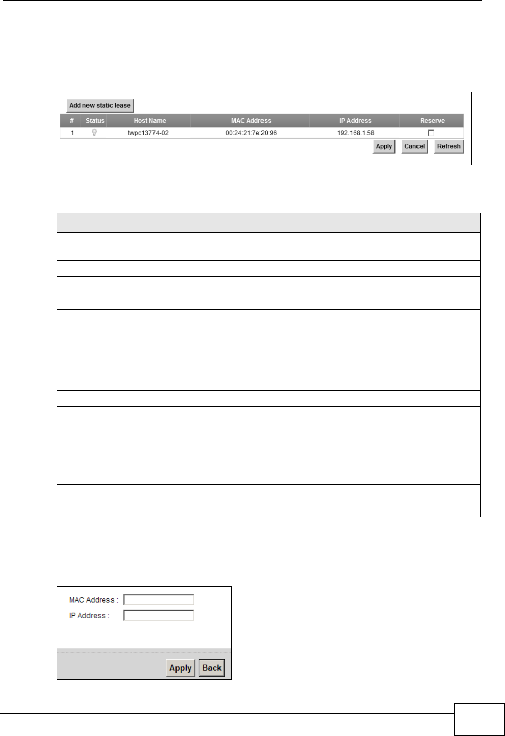
Chapter 7 Home Networking
P-2612HNU(L)-FxF User’s Guide 155
Use this screen to change your ZyXEL Device’s static DHCP settings. Click
Network Setting > Home Networking > Static DHCP to open the following
screen.
Figure 40 Network Setting > Home Networking > Static DHCP
The following table describes the labels in this screen.
If you click Add new static lease in the Static DHCP screen, the following
screen displays.
Figure 41 Static DHCP: Add
Table 26 Network Setting > Home Networking > Static DHCP
LABEL DESCRIPTION
Add new static
lease
Click this to add a new static DHCP entry.
# This is the index number of the entry.
Status This field displays whether the client is connected to the ZyXEL Device.
Host Name This field displays the client host name.
MAC Address The MAC (Media Access Control) or Ethernet address on a LAN (Local
Area Network) is unique to your computer (six pairs of hexadecimal
notation).
A network interface card such as an Ethernet adapter has a hardwired
address that is assigned at the factory. This address follows an industry
standard that ensures no other adapter has a similar address.
IP Address This field displays the IP address relative to the # field listed above.
Reserve Select the check box in the heading row to automatically select all
check boxes or select the check box(es) in each entry to have the
ZyXEL Device always assign the selected entry(ies)’s IP address(es) to
the corresponding MAC address(es) (and host name(s)). You can select
up to 128 entries in this table.
Apply Click Apply to save your changes.
Cancel Click Cancel to restore your previously saved settings.
Refresh Click Refresh to reload the DHCP table.
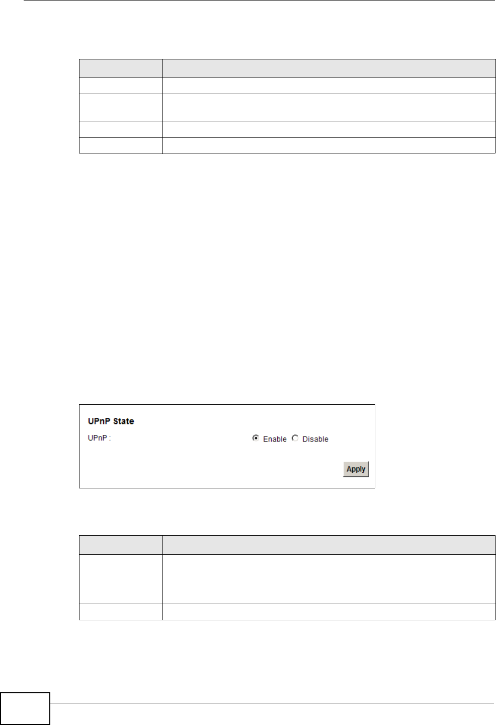
Chapter 7 Home Networking
P-2612HNU(L)-FxF User’s Guide
156
The following table describes the labels in this screen.
7.4 The UPnP Screen
Universal Plug and Play (UPnP) is a distributed, open networking standard that
uses TCP/IP for simple peer-to-peer network connectivity between devices. A
UPnP device can dynamically join a network, obtain an IP address, convey its
capabilities and learn about other devices on the network. In turn, a device can
leave a network smoothly and automatically when it is no longer in use.
See page 165 for more information on UPnP.
Use the following screen to configure the UPnP settings on your ZyXEL Device.
Click Network Setting > Home Networking > Static DHCP > UPnP to display
the screen shown next.
Figure 42 Network Setting > Home Networking > UPnP
The following table describes the labels in this screen.
Table 27 Static DHCP: Add
LABEL DESCRIPTION
MAC Address Enter the MAC address of a computer on your LAN.
IP Address Enter the IP address that you want to assign to the computer on your
LAN with the MAC address that you will also specify.
Apply Click Apply to save your changes.
Back Click Back to exit this screen without saving.
Table 28 Network Settings > Home Networking > UPnP
LABEL DESCRIPTION
UPnP Select Enable to activate UPnP. Be aware that anyone could use a
UPnP application to open the web configurator's login screen without
entering the ZyXEL Device's IP address (although you must still enter
the password to access the web configurator).
Apply Click Apply to save your changes.
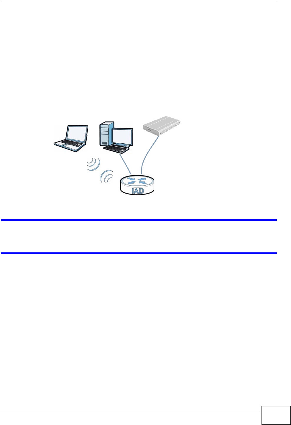
Chapter 7 Home Networking
P-2612HNU(L)-FxF User’s Guide 157
7.5 The File Sharing Screen
You can share files on a USB memory stick or hard drive connected to your ZyXEL
Device with users on your network.
The following figure is an overview of the ZyXEL Device’s file server feature.
Computers A and B can access files on a USB device (C) which is connected to the
ZyXEL Device.
Figure 43 File Sharing Overview
The ZyXEL Device will not be able to join the workgroup if your local area network
has restrictions set up that do not allow devices to join a workgroup. In this case,
contact your network administrator.
7.5.1 Before You Begin
Make sure the ZyXEL Device is connected to your network and turned on.
1Connect the USB device to one of the ZyXEL Device’s USB ports. Make sure the
ZyXEL Device is connected to your network.
2The ZyXEL Device detects the USB device and makes its contents available for
browsing. If you are connecting a USB hard drive that comes with an external
power supply, make sure it is connected to an appropriate power source that is on.
Note: If your USB device cannot be detected by ZyXEL Device, see the
troubleshooting for suggestions.
A
BC
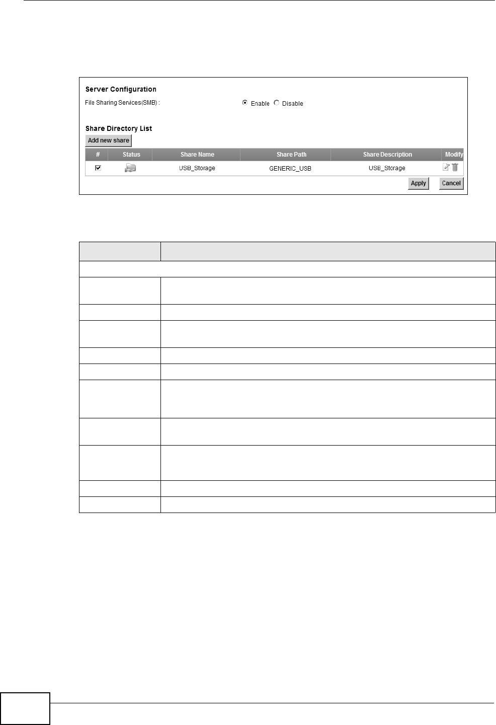
Chapter 7 Home Networking
P-2612HNU(L)-FxF User’s Guide
158
Use this screen to set up file sharing using the ZyXEL Device. To access this
screen, click Network Setting > Home Networking > File Sharing.
Figure 44 Network Setting > Home Networking > File Sharing
Each field is described in the following table.
Table 29 Network Setting > Home Networking > File Sharing
LABEL DESCRIPTION
Server Configuration
File Sharing
Services (SMB)
Select Enable to activate file sharing through the ZyXEL Device.
Add new share Click this to set up a new share on the ZyXEL Device.
# Select the check box to make the share available to the network.
Otherwise, clear this.
Status This shows whether or not the share is available for sharing.
Share Name This field displays the share name on the ZyXEL Device.
Share Path This field displays the path for the share directories (folders) on the
ZyXEL Device. These are the directories (folders) on your USB storage
device.
Share
Description
This field displays information about the share.
Modify Click the Edit icon to change the settings of an existing share.
Click the Delete icon to delete this share in the list.
Apply Click Apply to save your changes.
Cancel Click Cancel to restore your previously saved settings.
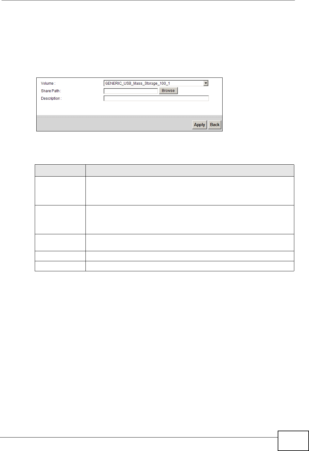
Chapter 7 Home Networking
P-2612HNU(L)-FxF User’s Guide 159
7.5.2 Add/Edit File Sharing
Use this screen to set up a new share or edit an existing share on the ZyXEL
Device. Click Add new share in the File Sharing screen or click the Edit icon
next to an existing share.
Figure 45 File Sharing: Add/Edit
Each field is described in the following table.
Table 30 File Sharing: Add/Edit
LABEL DESCRIPTION
Volume Select the volume in the USB storage device that you want to add as a
share in the ZyXEL Device.
This field is read-only when you are editing the share.
Share Path Manually enter the file path for the share, or click the Browse button
and select the folder that you want to add as a share.
This field is read-only when you are editing the share.
Description You can either enter a short description of the share, or leave this field
blank.
Apply Click Apply to save your changes.
Back Click Back to return to the previous screen.
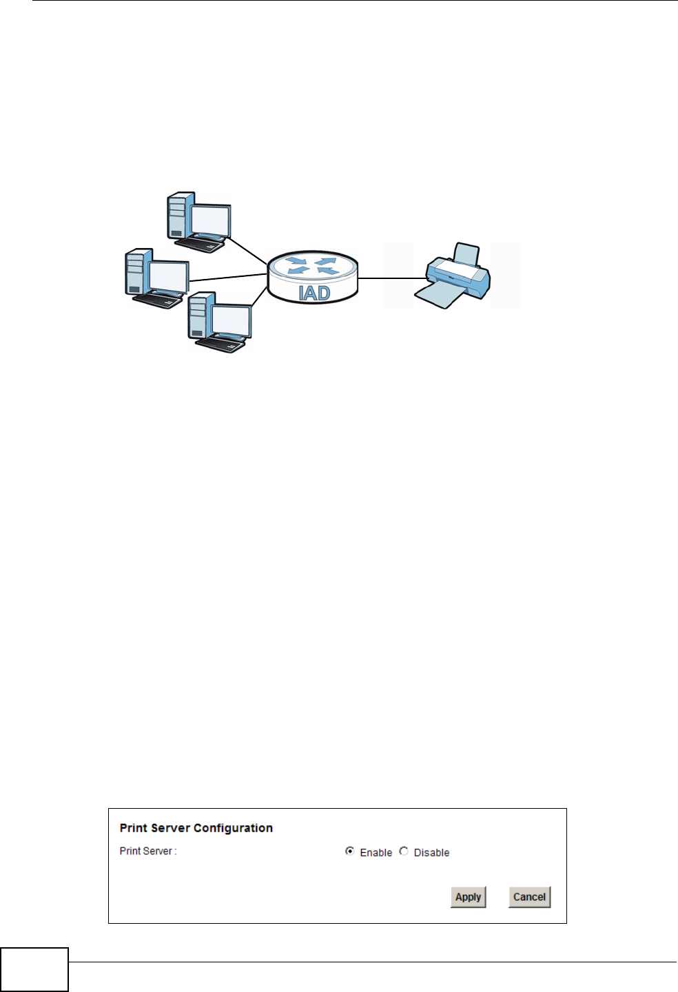
Chapter 7 Home Networking
P-2612HNU(L)-FxF User’s Guide
160
7.6 The Printer Server Screen
The ZyXEL Device allows you to share a USB printer on your LAN. You can do this
by connecting a USB printer to one of the USB ports on the ZyXEL Device and then
configuring a TCP/IP port on the computers connected to your network.
Figure 46 Sharing a USB Printer
7.6.1 Before You Begin
To configure the print server you need the following:
• Your ZyXEL Device must be connected to your computer and any other devices
on your network. The USB printer must be connected to your ZyXEL Device.
• A USB printer with the driver already installed on your computer.
• The computers on your network must have the printer software already installed
before they can create a TCP/IP port for printing via the network. Follow your
printer manufacturers instructions on how to install the printer software on your
computer.
Note: Your printer’s installation instructions may ask that you connect the printer to
your computer. Connect your printer to the ZyXEL Device instead.
Use this screen to enable or disable sharing of a USB printer via your ZyXEL
Device.
To access this screen, click Network Setting > Home Networking > Printer
Server.
Figure 47 Network Setting > Home Networking > Printer Server
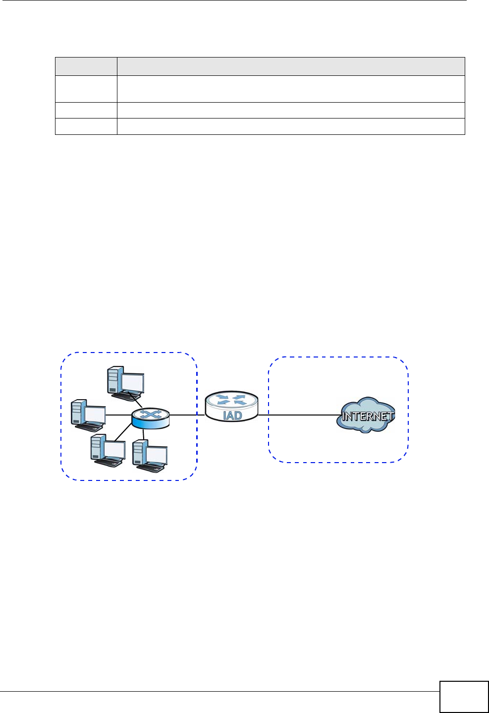
Chapter 7 Home Networking
P-2612HNU(L)-FxF User’s Guide 161
The following table describes the labels in this menu.
7.7 Technical Reference
This section provides some technical background information about the topics
covered in this chapter.
LANs, WANs and the ZyXEL Device
The actual physical connection determines whether the ZyXEL Device ports are
LAN or WAN ports. There are two separate IP networks, one inside the LAN
network and the other outside the WAN network as shown next.
Figure 48 LAN and WAN IP Addresses
DHCP Setup
DHCP (Dynamic Host Configuration Protocol, RFC 2131 and RFC 2132) allows
individual clients to obtain TCP/IP configuration at start-up from a server. You can
configure the ZyXEL Device as a DHCP server or disable it. When configured as a
server, the ZyXEL Device provides the TCP/IP configuration for the clients. If you
turn DHCP service off, you must have another DHCP server on your LAN, or else
the computer must be manually configured.
Table 31 Network Setting > Home Networking > Print Server
LABEL DESCRIPTION
Printer
Server
Select Enable to have the ZyXEL Device share a USB printer.
Apply Click Apply to save your changes.
Cancel Click Cancel to restore your previously saved settings.
WAN
LAN

Chapter 7 Home Networking
P-2612HNU(L)-FxF User’s Guide
162
IP Pool Setup
The ZyXEL Device is pre-configured with a pool of IP addresses for the DHCP
clients (DHCP Pool). See the product specifications in the appendices. Do not
assign static IP addresses from the DHCP pool to your LAN computers.
LAN TCP/IP
The ZyXEL Device has built-in DHCP server capability that assigns IP addresses
and DNS servers to systems that support DHCP client capability.
IP Address and Subnet Mask
Similar to the way houses on a street share a common street name, so too do
computers on a LAN share one common network number.
Where you obtain your network number depends on your particular situation. If
the ISP or your network administrator assigns you a block of registered IP
addresses, follow their instructions in selecting the IP addresses and the subnet
mask.
If the ISP did not explicitly give you an IP network number, then most likely you
have a single user account and the ISP will assign you a dynamic IP address when
the connection is established. If this is the case, it is recommended that you select
a network number from 192.168.0.0 to 192.168.255.0 and you must enable the
Network Address Translation (NAT) feature of the ZyXEL Device. The Internet
Assigned Number Authority (IANA) reserved this block of addresses specifically for
private use; please do not use any other number unless you are told otherwise.
Let's say you select 192.168.1.0 as the network number; which covers 254
individual addresses, from 192.168.1.1 to 192.168.1.254 (zero and 255 are
reserved). In other words, the first three numbers specify the network number
while the last number identifies an individual computer on that network.
Once you have decided on the network number, pick an IP address that is easy to
remember, for instance, 192.168.1.1, for your ZyXEL Device, but make sure that
no other device on your network is using that IP address.
The subnet mask specifies the network number portion of an IP address. Your
ZyXEL Device will compute the subnet mask automatically based on the IP
address that you entered. You don't need to change the subnet mask computed by
the ZyXEL Device unless you are instructed to do otherwise.
Private IP Addresses
Every machine on the Internet must have a unique address. If your networks are
isolated from the Internet, for example, only between your two branch offices, you
can assign any IP addresses to the hosts without problems. However, the Internet
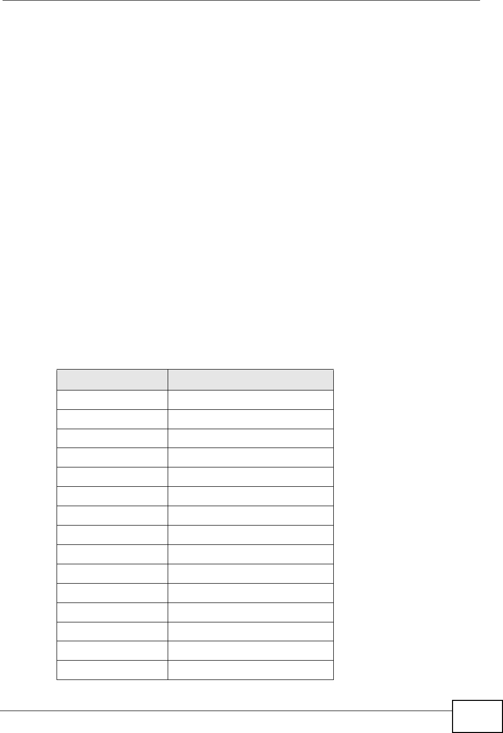
Chapter 7 Home Networking
P-2612HNU(L)-FxF User’s Guide 163
Assigned Numbers Authority (IANA) has reserved the following three blocks of IP
addresses specifically for private networks:
• 10.0.0.0 — 10.255.255.255
• 172.16.0.0 — 172.31.255.255
• 192.168.0.0 — 192.168.255.255
You can obtain your IP address from the IANA, from an ISP or it can be assigned
from a private network. If you belong to a small organization and your Internet
access is through an ISP, the ISP can provide you with the Internet addresses for
your local networks. On the other hand, if you are part of a much larger
organization, you should consult your network administrator for the appropriate IP
addresses.
Note: Regardless of your particular situation, do not create an arbitrary IP address;
always follow the guidelines above. For more information on address
assignment, please refer to RFC 1597, “Address Allocation for Private
Internets” and RFC 1466, “Guidelines for Management of IP Address Space”.
ZyXEL Device Print Server Compatible USB Printers
The following is a list of USB printer models compatible with the ZyXEL Device
print server.
Table 32 Compatible USB Printers
BRAND MODEL
Brother MFC7420
CANON BJ F9000
CANON i320
CANON PIXMA MP450
CANON PIXMA MP730
CANON PIXMA MP780
CANON PIXMA MP830
CANON PIXUS ip2500
CANON PIXMA ip4200
CANON PIXMA ip5000
CANON PIXUS 990i
EPSON CX3500
EPSON CX3900
EPSON EPL-5800
EPSON EPL-6200L
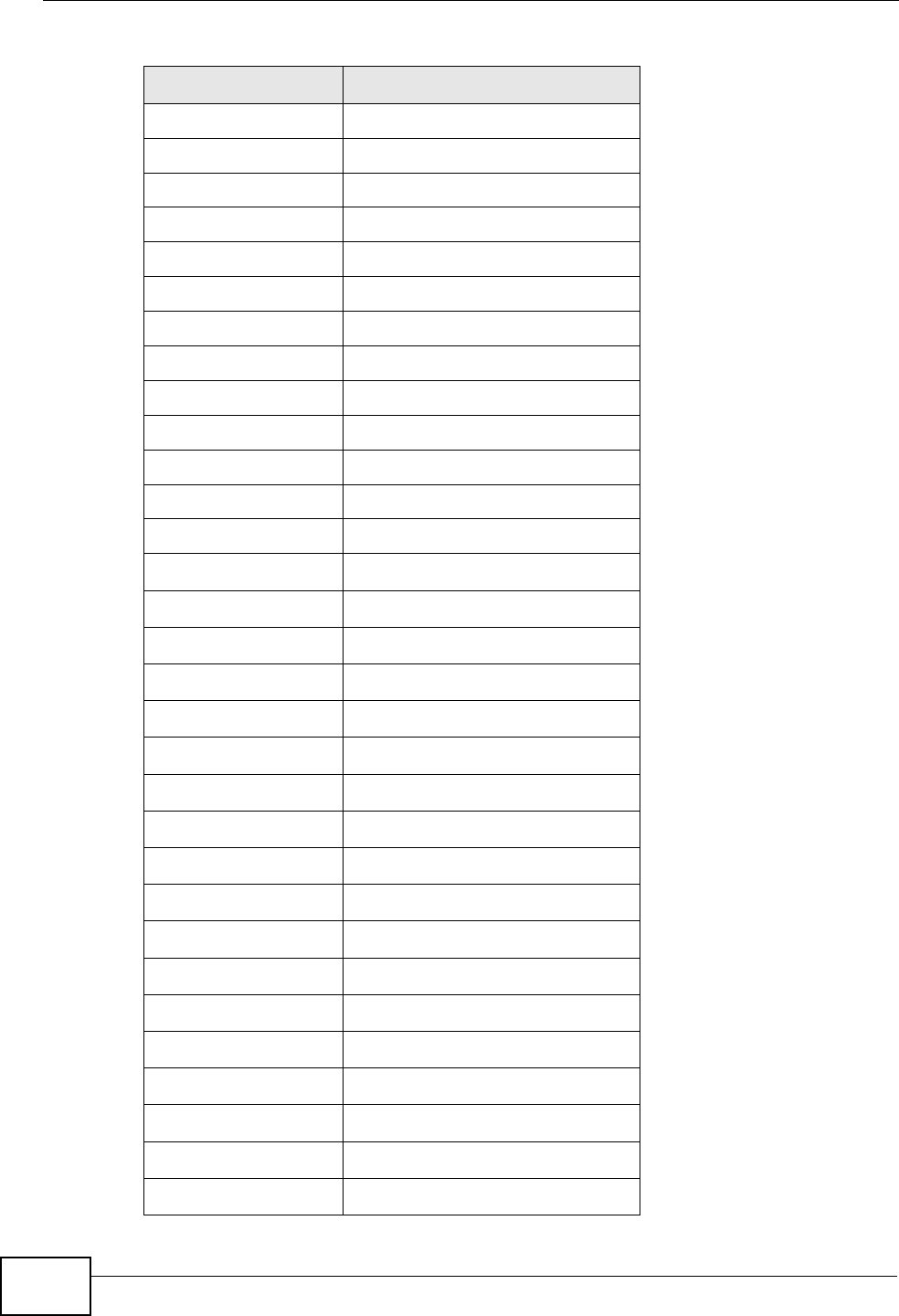
Chapter 7 Home Networking
P-2612HNU(L)-FxF User’s Guide
164
EPSON LP-2500
EPSON LP-8900
EPSON RX 510
EPSON RX 530
EPSON Stylus 830U
EPSON Stylus 1270
EPSON Stylus C43UX
EPSON Stylus C60
EPSON Stylus Color 670
HP Deskjet 5550
HP Deskjet 5652
HP Deskjet 830C
HP Deskjet 845C
HP Deskjet 1125C
HP Deskjet 1180C
HP Deskjet 1220C
HP Deskjet F4185
HP Laserjet 1022
HP Laserjet 1200
HP Laserjet 2200D
HP Laserjet 2420
HP Color Laserjet 1500L
HP Laserjet 3015
HP Officejet 4255
HP Officejet 5510
HP Officejet 5610
HP Officejet 7210
HP Officejet Pro L7380
HP Photosmart 2610
HP Photosmart 3110
HP Photosmart 7150
Table 32 Compatible USB Printers (continued)
BRAND MODEL
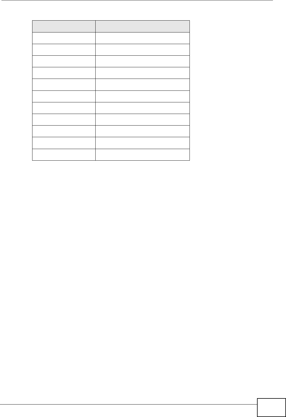
Chapter 7 Home Networking
P-2612HNU(L)-FxF User’s Guide 165
7.8 Installing UPnP in Windows Example
This section shows how to install UPnP in Windows Me and Windows XP.
Installing UPnP in Windows Me
Follow the steps below to install the UPnP in Windows Me.
1Click Start and Control Panel. Double-click Add/Remove Programs.
HP Photosmart 7830
HP Photosmart C5280
HP Photosmart D5160
HP PSC 1350
HP PSC 1410
IBM Infoprint 1332
LEXMARK Z55
LEXMARK Z705
OKI B4350
SAMSUNG ML-1710
SAMSUNG SCX-4016
Table 32 Compatible USB Printers (continued)
BRAND MODEL
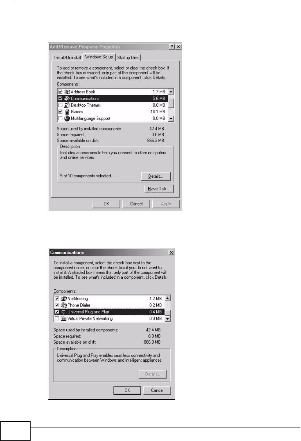
Chapter 7 Home Networking
P-2612HNU(L)-FxF User’s Guide
166
2Click the Windows Setup tab and select Communication in the Components
selection box. Click Details.
Figure 49 Add/Remove Programs: Windows Setup: Communication
3In the Communications window, select the Universal Plug and Play check box
in the Components selection box.
Figure 50 Add/Remove Programs: Windows Setup: Communication: Components
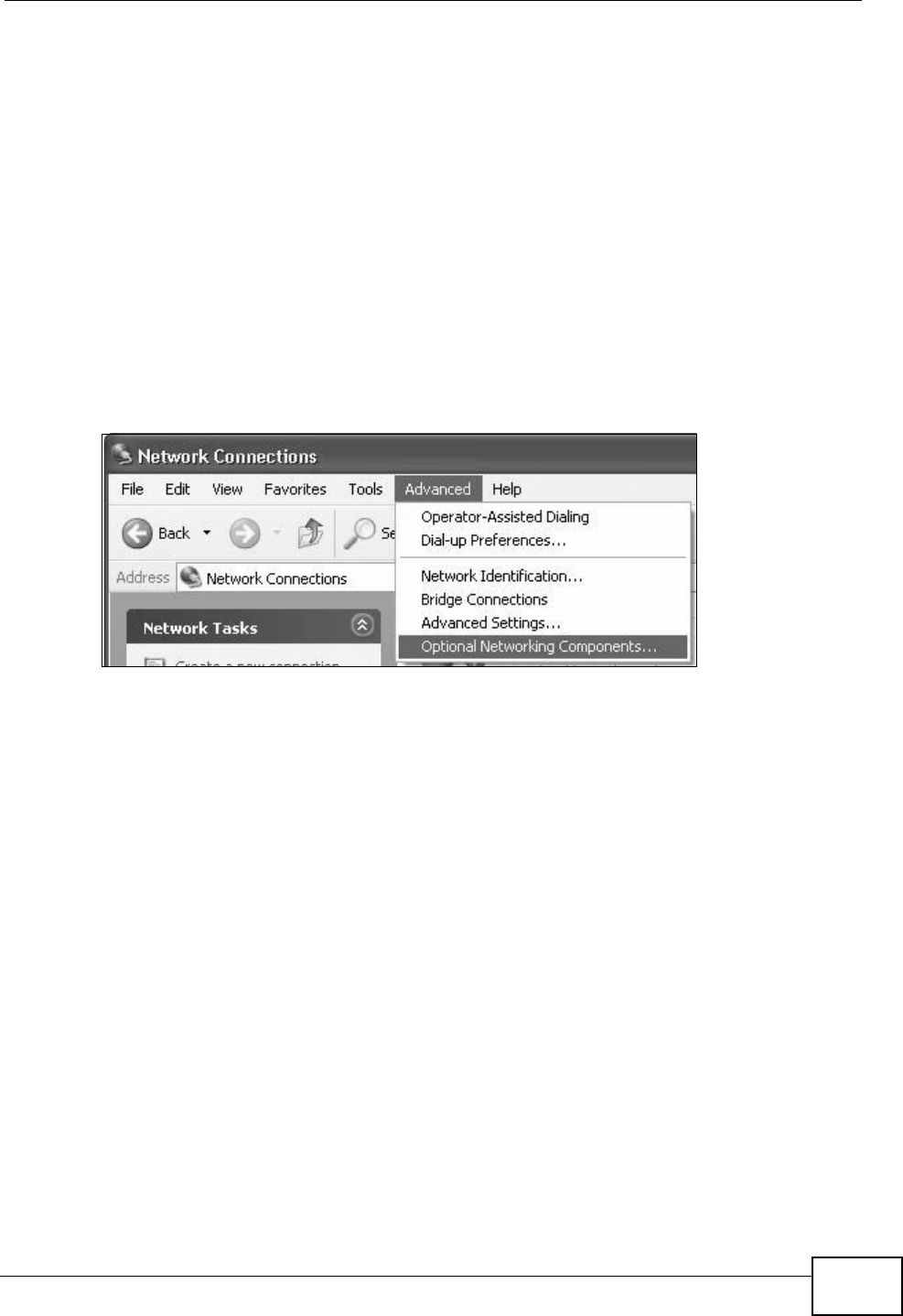
Chapter 7 Home Networking
P-2612HNU(L)-FxF User’s Guide 167
4Click OK to go back to the Add/Remove Programs Properties window and click
Next.
5Restart the computer when prompted.
Installing UPnP in Windows XP
Follow the steps below to install the UPnP in Windows XP.
1Click Start and Control Panel.
2Double-click Network Connections.
3In the Network Connections window, click Advanced in the main menu and
select Optional Networking Components ….
Figure 51 Network Connections
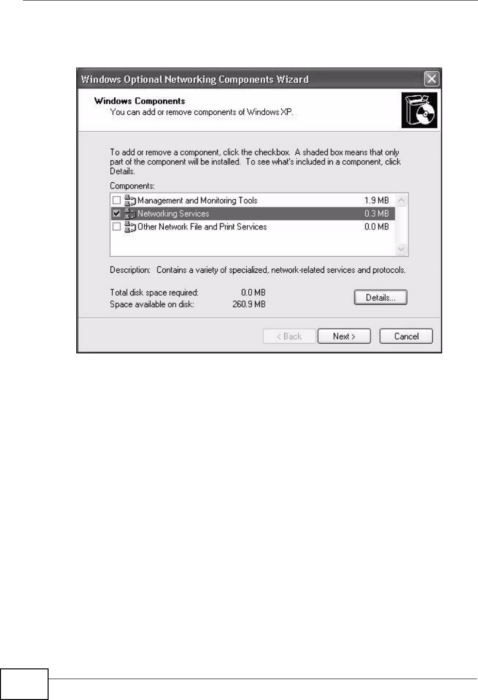
Chapter 7 Home Networking
P-2612HNU(L)-FxF User’s Guide
168
4The Windows Optional Networking Components Wizard window displays.
Select Networking Service in the Components selection box and click Details.
Figure 52 Windows Optional Networking Components Wizard
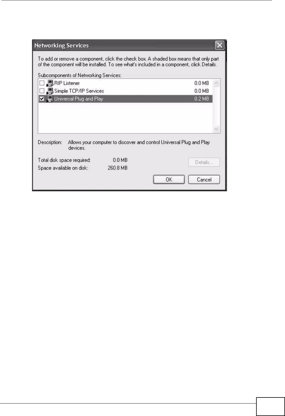
Chapter 7 Home Networking
P-2612HNU(L)-FxF User’s Guide 169
5In the Networking Services window, select the Universal Plug and Play check
box.
Figure 53 Networking Services
6Click OK to go back to the Windows Optional Networking Component Wizard
window and click Next.
7.9 Using UPnP in Windows XP Example
This section shows you how to use the UPnP feature in Windows XP. You must
already have UPnP installed in Windows XP and UPnP activated on the ZyXEL
Device.
Make sure the computer is connected to a LAN port of the ZyXEL Device. Turn on
your computer and the ZyXEL Device.
Auto-discover Your UPnP-enabled Network Device
1Click Start and Control Panel. Double-click Network Connections. An icon
displays under Internet Gateway.
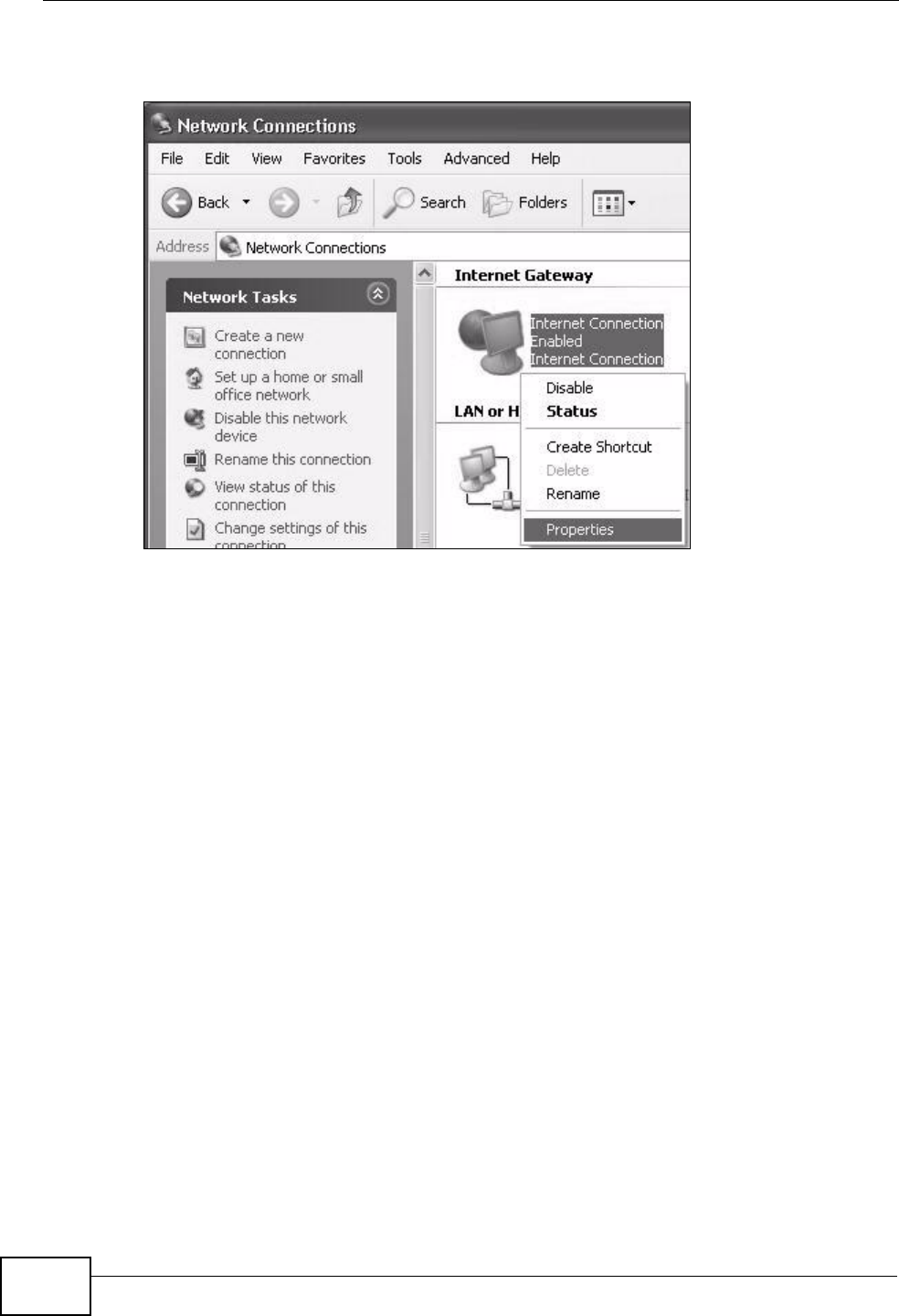
Chapter 7 Home Networking
P-2612HNU(L)-FxF User’s Guide
170
2Right-click the icon and select Properties.
Figure 54 Network Connections
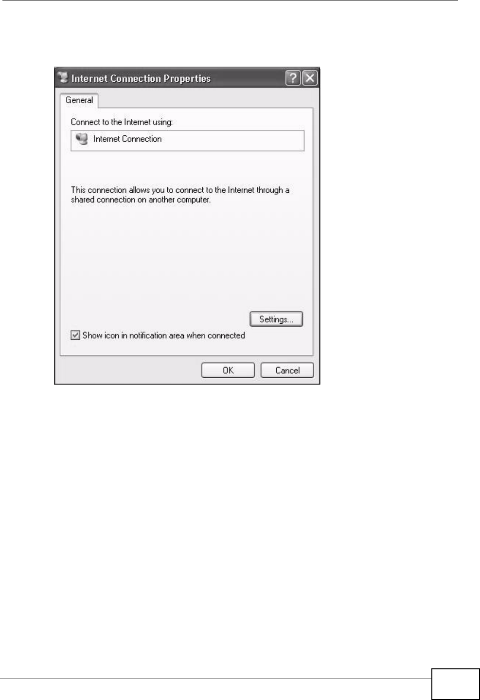
Chapter 7 Home Networking
P-2612HNU(L)-FxF User’s Guide 171
3In the Internet Connection Properties window, click Settings to see the port
mappings there were automatically created.
Figure 55 Internet Connection Properties
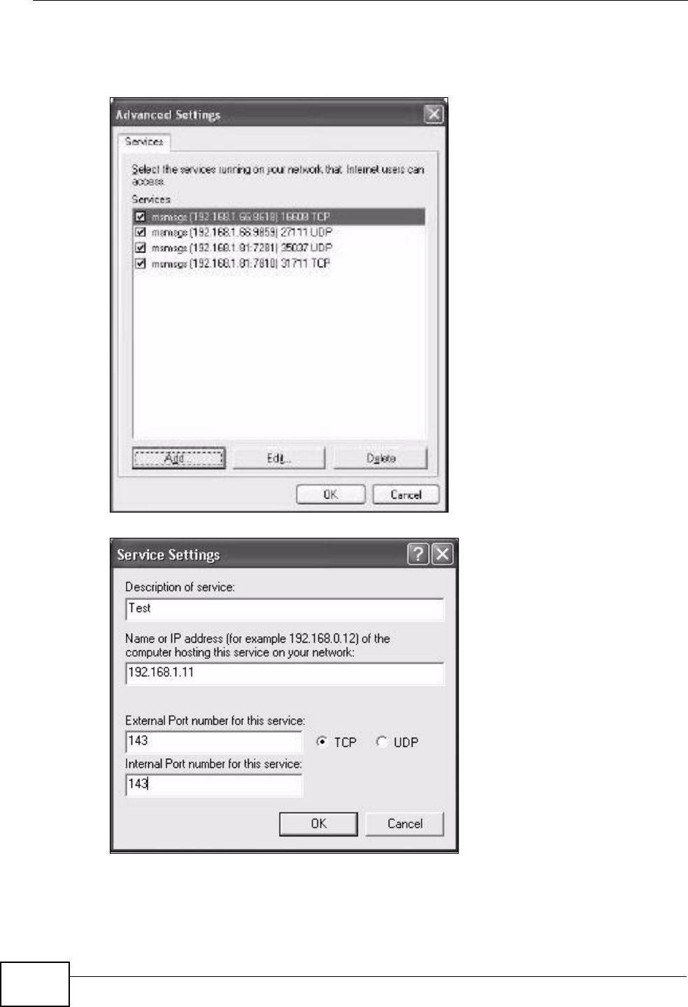
Chapter 7 Home Networking
P-2612HNU(L)-FxF User’s Guide
172
4You may edit or delete the port mappings or click Add to manually add port
mappings.
Figure 56 Internet Connection Properties: Advanced Settings
Figure 57 Internet Connection Properties: Advanced Settings: Add
5When the UPnP-enabled device is disconnected from your computer, all port
mappings will be deleted automatically.
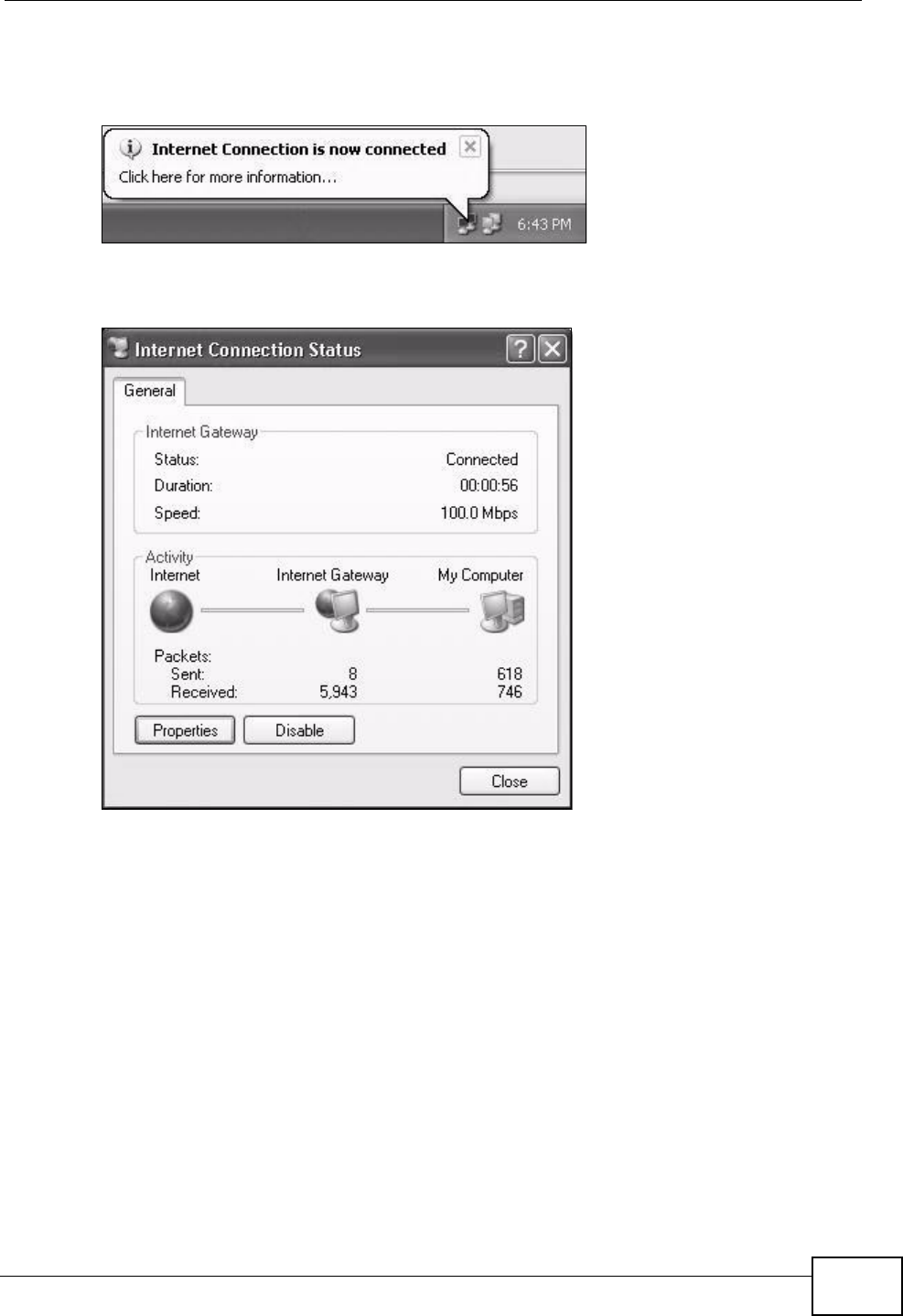
Chapter 7 Home Networking
P-2612HNU(L)-FxF User’s Guide 173
6Select Show icon in notification area when connected option and click OK.
An icon displays in the system tray.
Figure 58 System Tray Icon
7Double-click on the icon to display your current Internet connection status.
Figure 59 Internet Connection Status
Web Configurator Easy Access
With UPnP, you can access the web-based configurator on the ZyXEL Device
without finding out the IP address of the ZyXEL Device first. This comes helpful if
you do not know the IP address of the ZyXEL Device.
Follow the steps below to access the web configurator.
1Click Start and then Control Panel.
2Double-click Network Connections.
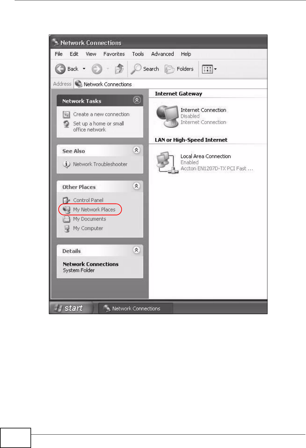
Chapter 7 Home Networking
P-2612HNU(L)-FxF User’s Guide
174
3Select My Network Places under Other Places.
Figure 60 Network Connections
4An icon with the description for each UPnP-enabled device displays under Local
Network.
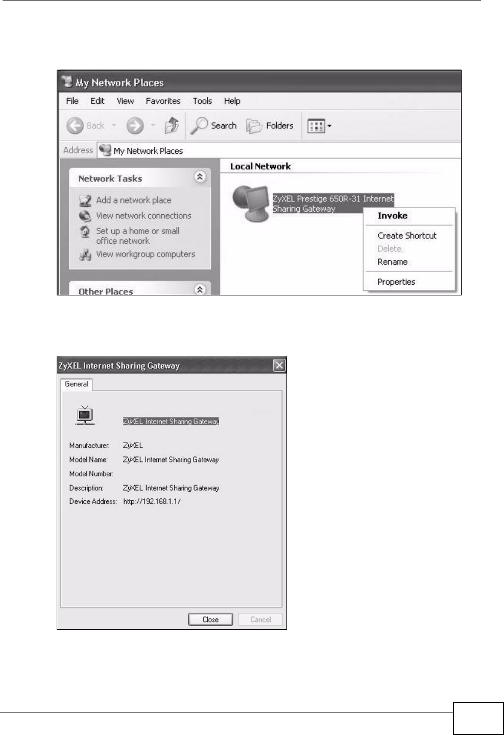
Chapter 7 Home Networking
P-2612HNU(L)-FxF User’s Guide 175
5Right-click on the icon for your ZyXEL Device and select Invoke. The web
configurator login screen displays.
Figure 61 Network Connections: My Network Places
6Right-click on the icon for your ZyXEL Device and select Properties. A properties
window displays with basic information about the ZyXEL Device.
Figure 62 Network Connections: My Network Places: Properties: Example

Chapter 7 Home Networking
P-2612HNU(L)-FxF User’s Guide
176
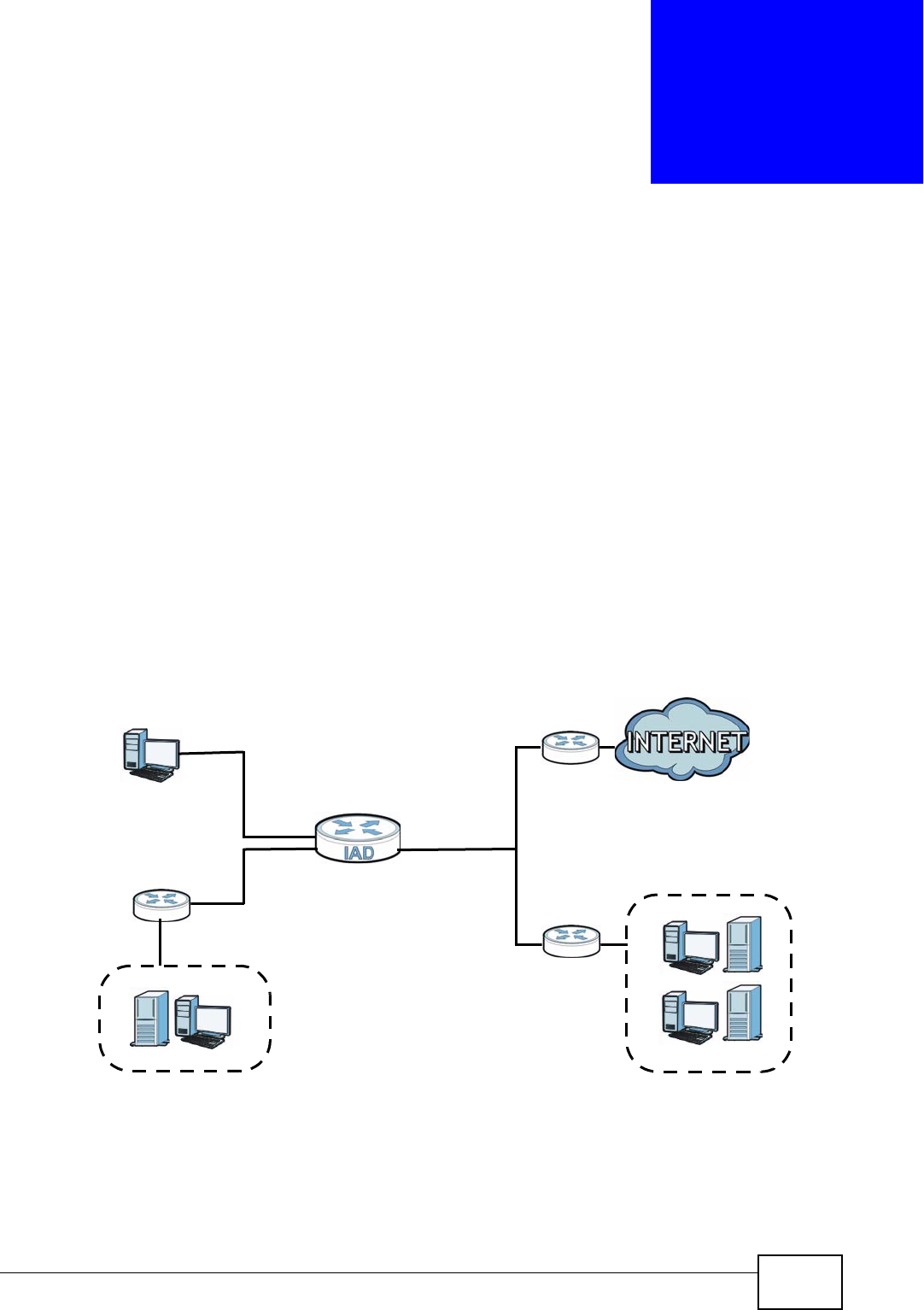
P-2612HNU(L)-FxF User’s Guide 177
CHAPTER 8
Routing
8.1 Overview
The ZyXEL Device usually uses the default gateway to route outbound traffic from
computers on the LAN to the Internet. To have the ZyXEL Device send data to
devices not reachable through the default gateway, use static routes.
For example, the next figure shows a computer (A) connected to the ZyXEL
Device’s LAN interface. The ZyXEL Device routes most traffic from A to the
Internet through the ZyXEL Device’s default gateway (R1). You create one static
route to connect to services offered by your ISP behind router R2. You create
another static route to communicate with a separate network behind a router R3
connected to the LAN.
Figure 63 Example of Static Routing Topology
WAN
R1
R2
A
R3
LAN

Chapter 8 Routing
P-2612HNU(L)-FxF User’s Guide
178
8.2 Configuring Static Route
Use this screen to view and configure IP static routes on the ZyXEL Device. Click
Network Setting > Routing to open the following screen.
Figure 64 Network Setting > Routing
The following table describes the labels in this screen.
Table 33 Network Setting > Routing
LABEL DESCRIPTION
Add New
Static Route
Click this to set up a new static route on the ZyXEL Device.
# This is the number of an individual static route.
Active This indicates whether the rule is active or not.
A yellow bulb signifies that this static route is active. A gray bulb signifies
that this static route is not active.
Status This shows whether the static route is currently in use or not. A yellow
bulb signifies that this static route is in use. A gray bulb signifies that this
static route is not in use.
Name This is the name that describes or identifies this route.
Destination IP This parameter specifies the IP network address of the final destination.
Routing is always based on network number.
Gateway This is the IP address of the gateway. The gateway is a router or switch
on the same network segment as the device's LAN or WAN port. The
gateway helps forward packets to their destinations.
Subnet Mask This parameter specifies the IP network subnet mask of the final
destination.
Interface This is the WAN interface through which the traffic is routed.
Modify Click the Edit icon to go to the screen where you can set up a static route
on the ZyXEL Device.
Click the Delete icon to remove a static route from the ZyXEL Device.
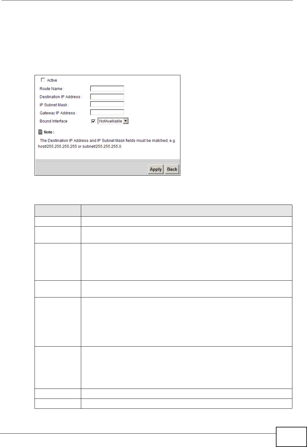
Chapter 8 Routing
P-2612HNU(L)-FxF User’s Guide 179
8.2.1 Add/Edit Static Route
Click add new Static Route in the Routing screen or click the Edit icon next to
a rule. The following screen appears. Use this screen to configure the required
information for a static route.
Figure 65 Routing: Add/Edit
The following table describes the labels in this screen.
Table 34 Routing: Add/Edit
LABEL DESCRIPTION
Active Click this to activate this static route.
Route Name Enter the name of the IP static route. Leave this field blank to delete this
static route.
Destination IP
Address
This parameter specifies the IP network address of the final destination.
Routing is always based on network number. If you need to specify a
route to a single host, use a subnet mask of 255.255.255.255 in the
subnet mask field to force the network number to be identical to the host
ID.
IP Subnet
Mask
Enter the IP subnet mask here.
Gateway IP
Address
You can decide if you want to forward packets to a gateway IP address or
a bound interface.
If you want to configure Gateway IP Address, enter the IP address of
the next-hop gateway. The gateway is a router or switch on the same
network segment as the device's LAN or WAN port. The gateway helps
forward packets to their destinations.
Bound
Interface
You can decide if you want to forward packets to a gateway IP address or
a bound interface.
If you want to configure Bound Interface, select the check box and
choose an interface through which the traffic is sent. You must have the
WAN interface(s) already configured in the Broadband screen.
Apply Click Apply to save your changes.
Back Click Back to exit this screen without saving.

Chapter 8 Routing
P-2612HNU(L)-FxF User’s Guide
180
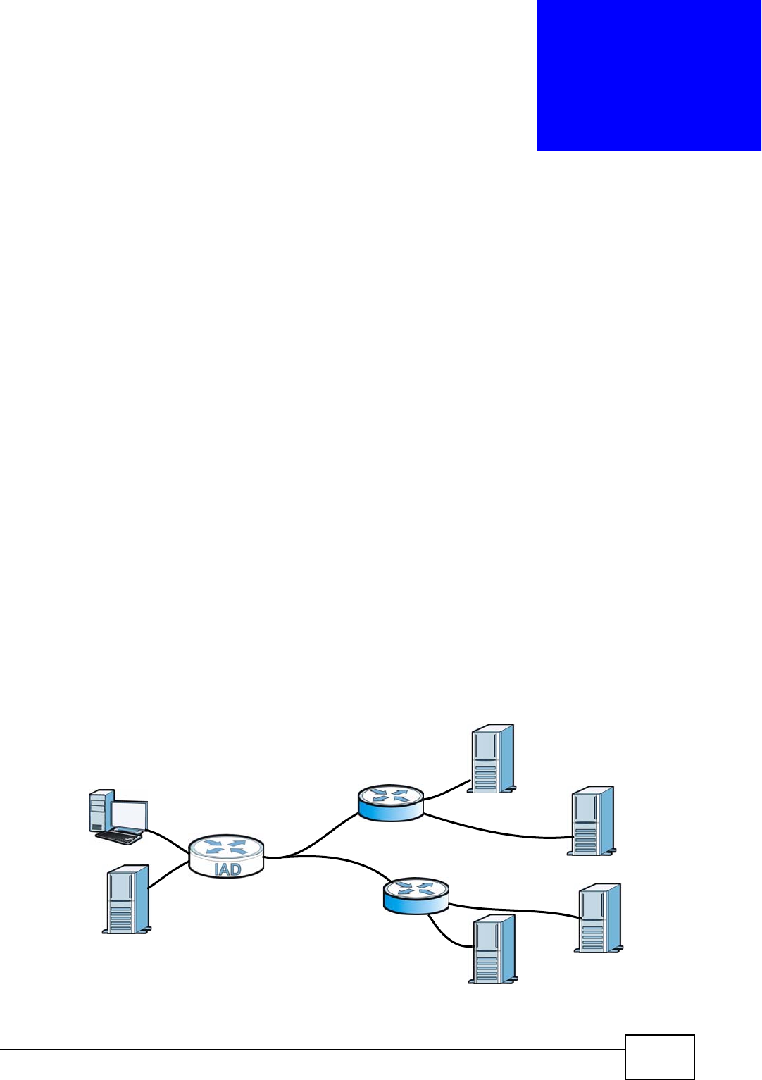
P-2612HNU(L)-FxF User’s Guide 181
CHAPTER 9
DNS Route
9.1 Overview
DNS (Domain Name System) is for mapping a domain name to its corresponding
IP address and vice versa. The DNS server is extremely important because
without it, you must know the IP address of a machine before you can access it.
In addition to the system DNS server(s), each WAN interface (service) is set to
have its own static or dynamic DNS server list. You can configure a DNS static
route to forward DNS queries for certain domain names through a specific WAN
interface to its DNS server(s). The ZyXEL Device uses a system DNS server (in the
order you specify in the Broadband screen) to resolve domain names that do not
match any DNS routing entry. After the ZyXEL Device receives a DNS reply from a
DNS server, it creates a new entry for the resolved IP address in the routing table.
In the following example, the DNS server 168.92.5.1 obtained from the WAN
interface ptm0.100 is set to be the system DNS server. The DNS server
10.10.23.7 is obtained from the WAN interface ppp1.123. You configure a DNS
route for *example.com to have the ZyXEL Device forward DNS requests for the
domain name mail.example.com through the WAN interface ppp1.123 to the DNS
server 10.10.23.7.
Figure 66 Example of DNS Routing Topology
WAN
LAN
ptm0.100
ppp1.123
DNS:10.10.23.7
DNS:168.92.5.1
sip.service.com
mail.example.com
(Default)
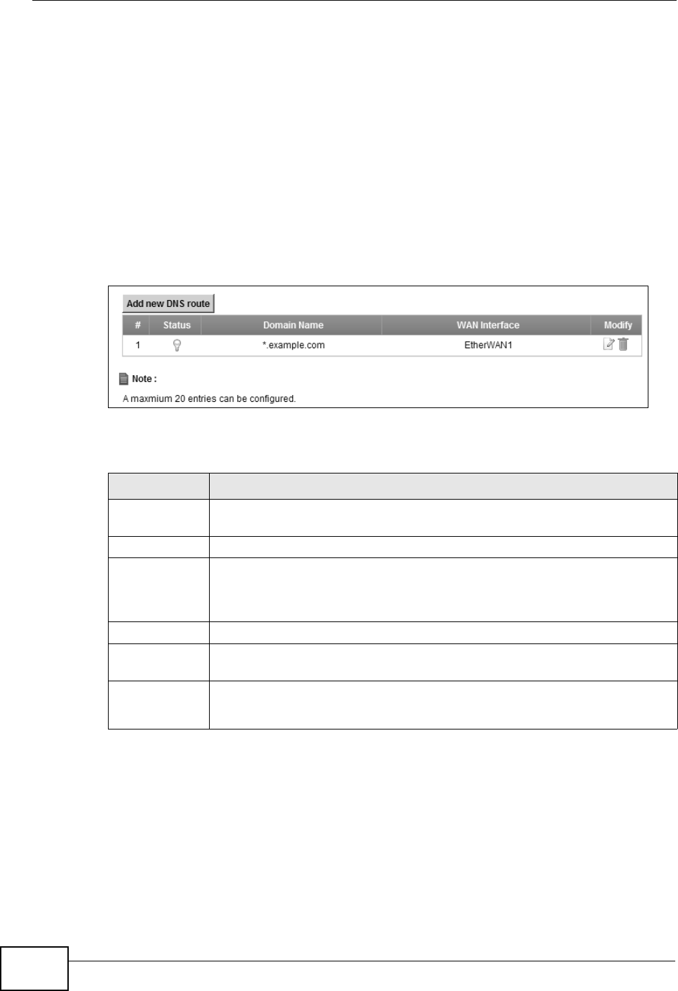
Chapter 9 DNS Route
P-2612HNU(L)-FxF User’s Guide
182
9.1.1 What You Can Do in this Chapter
The DNS Route screens let you view and configure DNS routes on the ZyXEL
Device (Section 9.2 on page 182).
9.2 The DNS Route Screen
The DNS Route screens let you view and configure DNS routes on the ZyXEL
Device. Click Network Setting > DNS Route to open the DNS Route screen.
Figure 67 Network Setting > DNS Route
The following table describes the labels in this screen.
Table 35 Network Setting > DNS Route
LABEL DESCRIPTION
Add new DNS
route
Click this to create a new entry.
# This is the number of an individual DNS route.
Status This shows whether the DNS route is currently in use or not.
A yellow bulb signifies that this DNS route is in use. A gray bulb signifies
that this DNS route is not in use.
Domain Name This is the domain name to which the DNS route applies.
WAN Interface This is the WAN interface through which the matched DNS request is
routed.
Modify Click the Edit icon to configure a DNS route on the ZyXEL Device.
Click the Delete icon to remove a DNS route from the ZyXEL Device.
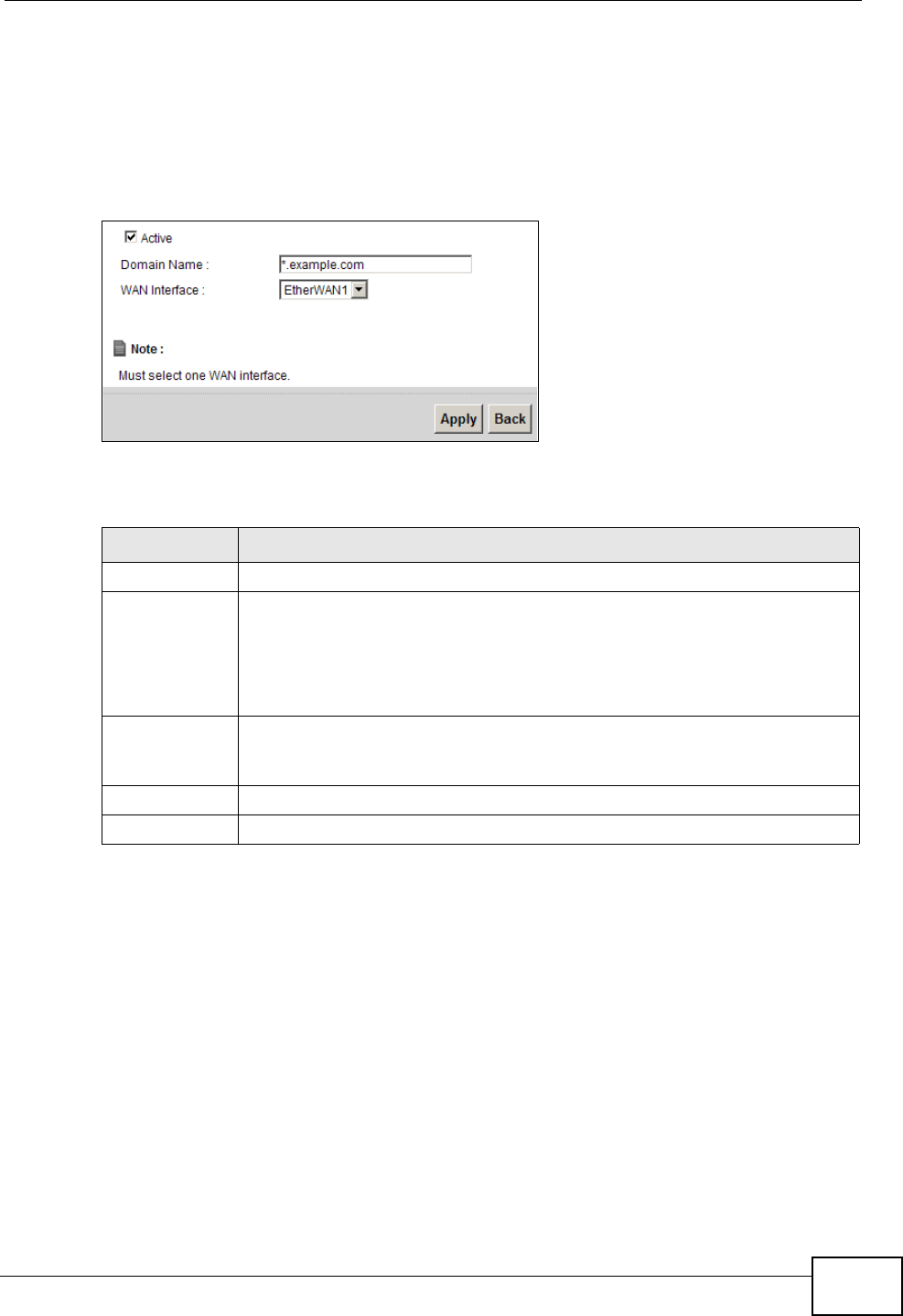
Chapter 9 DNS Route
P-2612HNU(L)-FxF User’s Guide 183
9.2.1 Add/Edit DNS Route Edit
Click Add new DNS route in the DNS Route screen or the Edit icon next to an
existing DNS route. Use this screen to configure the required information for a
DNS route.
Figure 68 DNS Route: Add/Edit
The following table describes the labels in this screen.
Table 36 DNS Route: Add/Edit
LABEL DESCRIPTION
Active Select this to activate this DNS route.
Domain Name Enter the domain name you want to resolve.
You can use the wildcard character, an “*” (asterisk) as the left most part
of a domain name, such as *.example.com. The ZyXEL Device forwards
DNS queries for any domain name ending in example.com to the WAN
interface specified in this route.
WAN Interface Select a WAN interface through which the matched DNS query is sent.
You must have the WAN interface(s) already configured in the
Broadband screen.
Apply Click Apply to save your changes.
Back Click Back to exit this screen without saving.

Chapter 9 DNS Route
P-2612HNU(L)-FxF User’s Guide
184

P-2612HNU(L)-FxF User’s Guide 185
CHAPTER 10
Quality of Service (QoS)
10.1 Overview
This chapter discusses the ZyXEL Device’s QoS screens. Use these screens to set
up your ZyXEL Device to use QoS for traffic management.
Quality of Service (QoS) refers to both a network’s ability to deliver data with
minimum delay, and the networking methods used to control the use of
bandwidth. QoS allows the ZyXEL Device to group and prioritize application traffic
and fine-tune network performance.
Without QoS, all traffic data is equally likely to be dropped when the network is
congested. This can cause a reduction in network performance and make the
network inadequate for time-critical application such as video-on-demand.
The ZyXEL Device assigns each packet a priority and then queues the packet
accordingly. Packets assigned a high priority are processed more quickly than
those with low priority if there is congestion, allowing time-sensitive applications
to flow more smoothly. Time-sensitive applications include both those that require
a low level of latency (delay) and a low level of jitter (variations in delay) such as
Internet gaming, and those for which jitter alone is a problem such as Internet
radio or streaming video.
Note: The ZyXEL Device has built-in configurations for Voice over IP (IP). The Quality
of Service (QoS) feature does not affect VoIP traffic.
• See Section 10.6 on page 195 for advanced technical information on SIP.
10.1.1 What You Can Do in this Chapter
• Use the General screen to enable QoS, set the bandwidth, and allow the ZyXEL
Device to automatically assign priority to upstream traffic according to the IEEE
802.1p priority level, IP precedence or packet length (Section 10.2 on page
186).
• Use the Queue Setup screen to configure QoS queue assignment (Section 10.3
on page 188).

Chapter 10 Quality of Service (QoS)
P-2612HNU(L)-FxF User’s Guide
186
• Use the Class Setup screen to set up classifiers to sort traffic into different
flows and assign priority and define actions to be performed for a classified
traffic flow (Section 10.4 on page 190).
• Use the Monitor screen to view the ZyXEL Device’s QoS-related packet
statistics (Section 10.5 on page 194).
10.1.2 What You Need to Know
The following terms and concepts may help as you read this chapter.
QoS versus Cos
QoS is used to prioritize source-to-destination traffic flows. All packets in the same
flow are given the same priority. CoS (class of service) is a way of managing traffic
in a network by grouping similar types of traffic together and treating each type as
a class. You can use CoS to give different priorities to different packet types.
CoS technologies include IEEE 802.1p layer 2 tagging and DiffServ (Differentiated
Services or DS). IEEE 802.1p tagging makes use of three bits in the packet
header, while DiffServ is a new protocol and defines a new DS field, which replaces
the eight-bit ToS (Type of Service) field in the IP header.
Tagging and Marking
In a QoS class, you can configure whether to add or change the DSCP (DiffServ
Code Point) value, IEEE 802.1p priority level and VLAN ID number in a matched
packet. When the packet passes through a compatible network, the networking
device, such as a backbone switch, can provide specific treatment or service
based on the tag or marker.
10.2 The QoS General Screen
Use this screen to enable or disable QoS, set the bandwidth, and select to have
the ZyXEL Device automatically assign priority to upstream traffic according to the
IEEE 802.1p priority level, IP precedence or packet length.
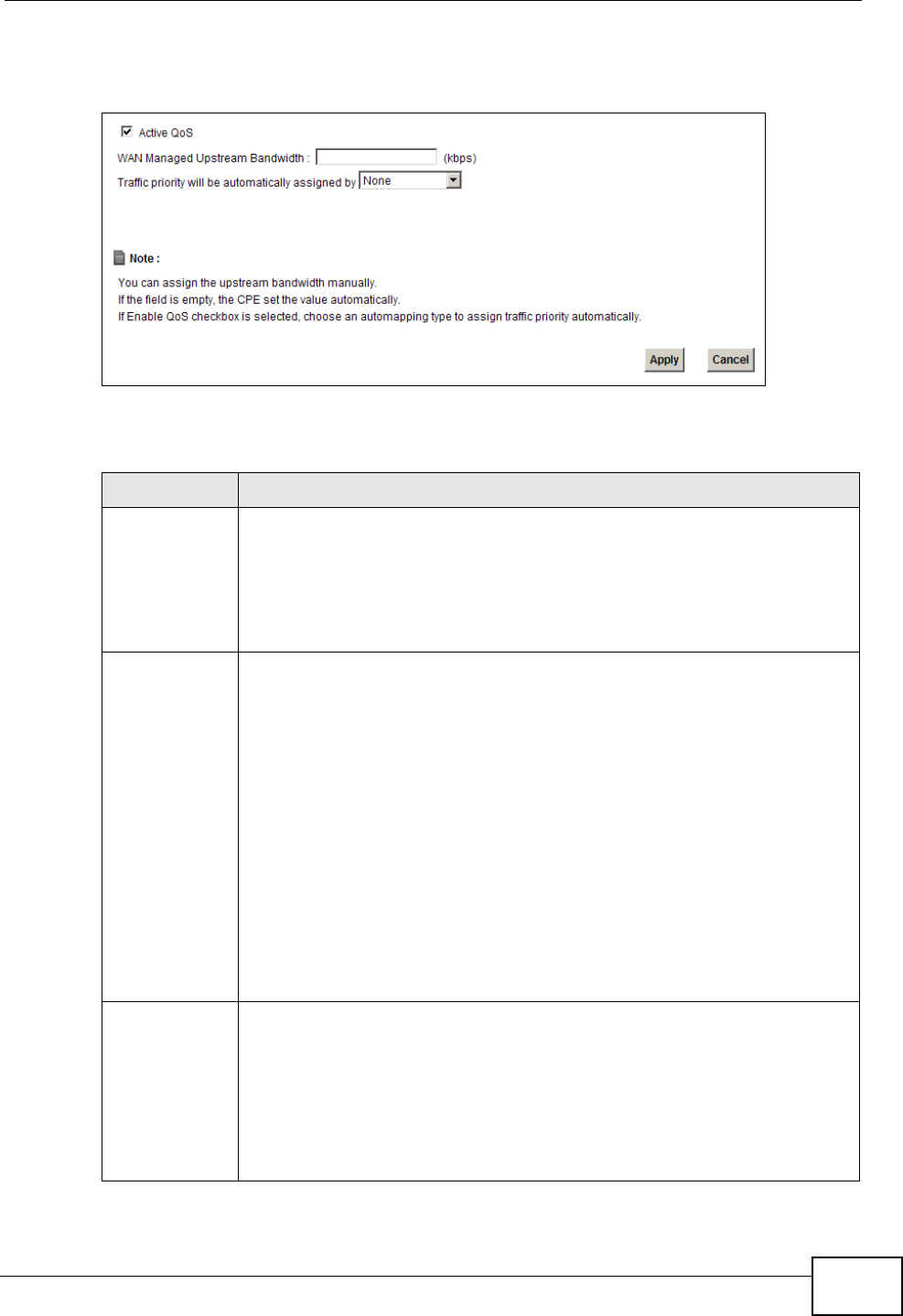
Chapter 10 Quality of Service (QoS)
P-2612HNU(L)-FxF User’s Guide 187
Click Network Setting > QoS to open the General screen.
Figure 69 Network Setting > QoS > General
The following table describes the labels in this screen.
Table 37 Network Setting > QoS > General
LABEL DESCRIPTION
Active QoS Select the check box to turn on QoS to improve your network
performance.
You can give priority to traffic that the ZyXEL Device forwards out
through the WAN interface. Give high priority to voice and video to make
them run more smoothly. Similarly, give low priority to many large file
downloads so that they do not reduce the quality of other applications.
WAN Managed
Upstream
Bandwidth
Enter the amount of bandwidth for the WAN interface that you want to
allocate using QoS.
The recommendation is to set this speed to match the interface’s actual
transmission speed. For example, set the WAN interface speed to 100000
kbps if your Internet connection has an upstream transmission speed of
100 Mbps.
Setting this number higher than the interface’s actual transmission speed
will stop lower priority traffic from being sent if higher priority traffic uses
all of the actual bandwidth.
If you set this number lower than the interface’s actual transmission
speed, the ZyXEL Device will not use some of the interface’s available
bandwidth.
Leave this field blank to have the ZyXEL Device set this value
automatically.
Traffic priority
will be
automatically
assigned by
These fields are ignored if upstream traffic matches a class you
configured in the Class Setup screen.
If you select Ethernet Priority, IP Precedence or Packet Length and
traffic does not match a class configured in the Class Setup screen, the
ZyXEL Device assigns priority to unmatched traffic based on the IEEE
802.1p priority level, IP precedence or packet length.
See Section 10.6.1 on page 195 for more information.
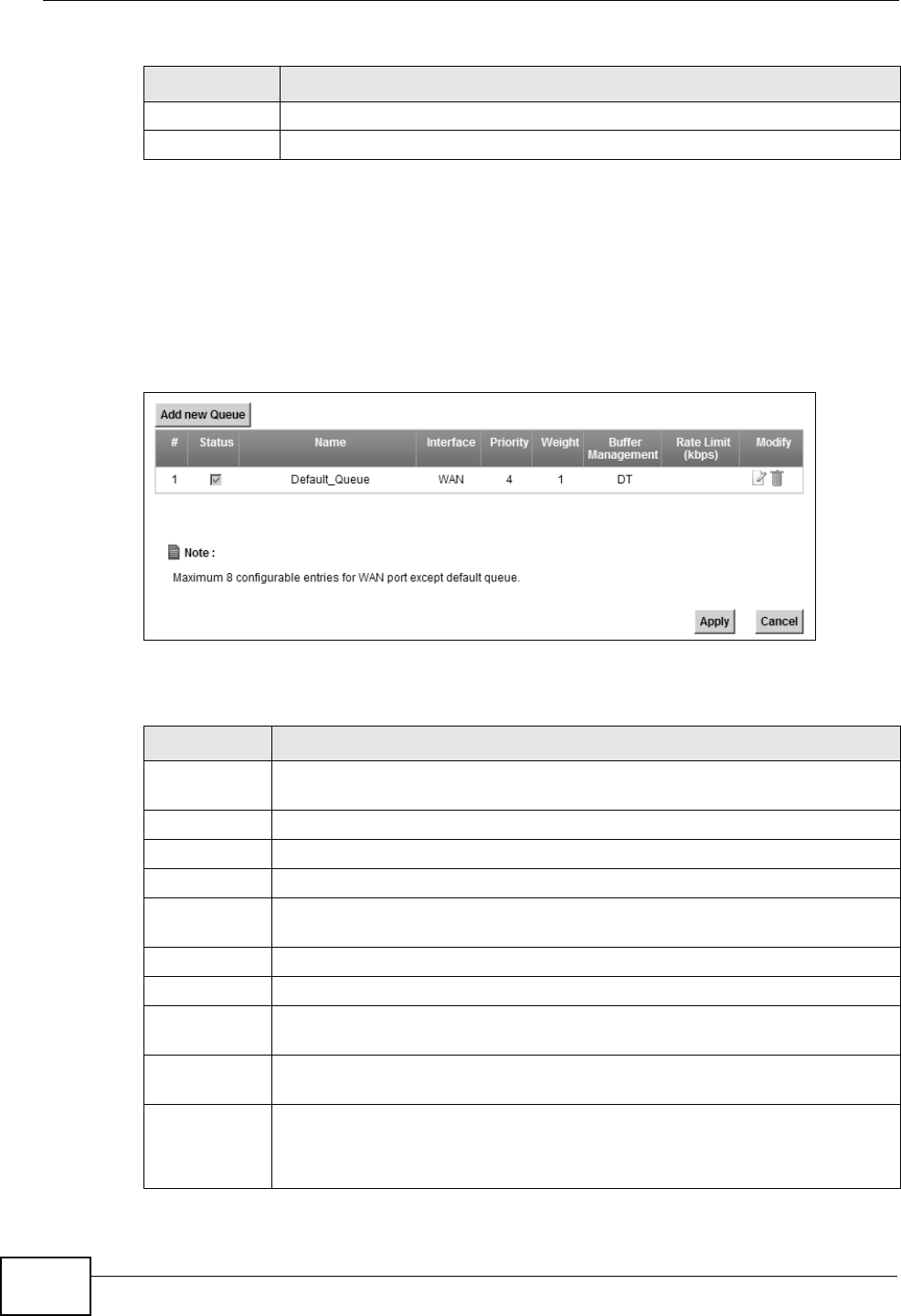
Chapter 10 Quality of Service (QoS)
P-2612HNU(L)-FxF User’s Guide
188
10.3 The Queue Setup Screen
Use this screen to configure QoS queue assignment. Click Network Setting >
QoS > Queue Setup to open the screen as shown next.
Figure 70 Network Setting > QoS > Queue Setup
The following table describes the labels in this screen.
Apply Click Apply to save your changes.
Cancel Click Cancel to restore your previously saved settings.
Table 37 Network Setting > QoS > General (continued)
LABEL DESCRIPTION
Table 38 Network Setting > QoS > Queue Setup
LABEL DESCRIPTION
Add new
Queue
Click this to create a new entry.
# This is the index number of this entry.
Status Select the check box to enable the queue.
Name This shows the descriptive name of this queue.
Interface This shows the name of the ZyXEL Device’s interface through which traffic
in this queue passes.
Priority This shows the priority of this queue.
Weight This shows the weight of this queue.
Buffer
Management
This shows the queue management algorithm used by the ZyXEL Device.
Rate Limit
(kbps)
This shows the maximum transmission rate allowed for traffic on this
queue.
Modify Click the Edit icon to edit the queue.
Click the Delete icon to delete an existing queue. Note that subsequent
rules move up by one when you take this action.
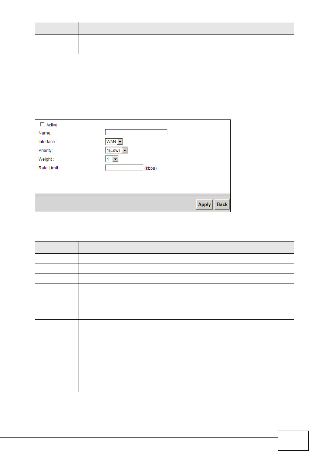
Chapter 10 Quality of Service (QoS)
P-2612HNU(L)-FxF User’s Guide 189
10.3.1 Add/Edit a QoS Queue
Use this screen to configure a queue. Click Add new queue in the Queue Setup
screen or the Edit icon next to an existing queue.
Figure 71 Queue Setup: Add/Edit
The following table describes the labels in this screen.
Apply Click Apply to save your changes.
Cancel Click Cancel to restore your previously saved settings.
Table 38 Network Setting > QoS > Queue Setup (continued)
LABEL DESCRIPTION
Table 39 Queue Setup: Add/Edit
LABEL DESCRIPTION
Active Select to enable or disable this queue.
Name Enter the descriptive name of this queue.
Interface Select the interface to which this queue is applied.
Priority Select the priority level (from 1 to 7) of this queue.
The larger the number, the higher the priority level. Traffic assigned to
higher priority queues gets through faster while traffic in lower priority
queues is dropped if the network is congested.
Weight Select the weight (from 1 to 15) of this queue.
If two queues have the same priority level, the ZyXEL Device divides the
bandwidth across the queues according to their weights. Queues with
larger weights get more bandwidth than queues with smaller weights.
Rate Limit Specify the maximum transmission rate (in Kbps) allowed for traffic on
this queue.
Apply Click Apply to save your changes.
Back Click Back to return to the previous screen without saving.
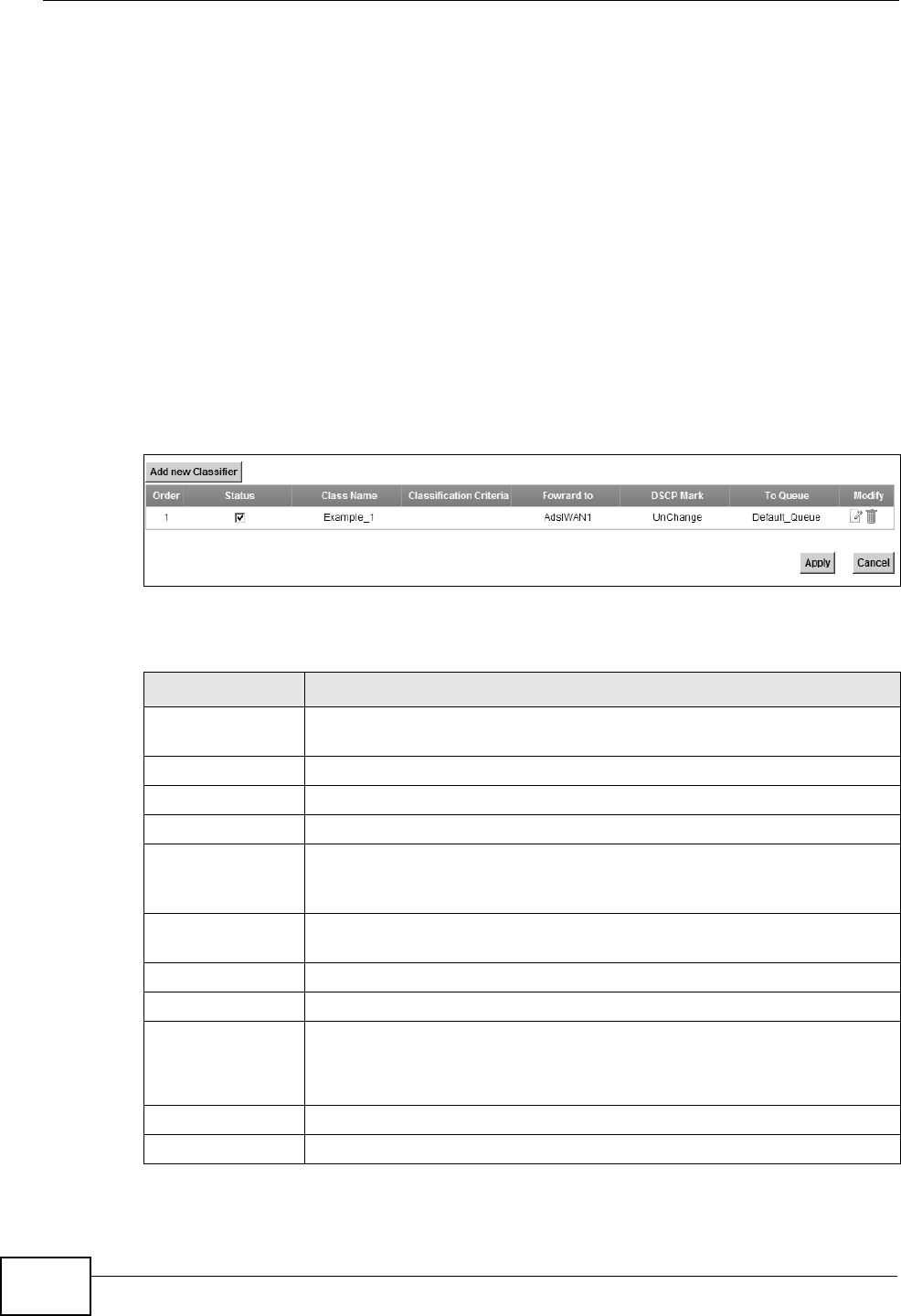
Chapter 10 Quality of Service (QoS)
P-2612HNU(L)-FxF User’s Guide
190
10.4 The Class Setup Screen
Use this screen to add, edit or delete QoS classifiers. A classifier groups traffic into
data flows according to specific criteria such as the source address, destination
address, source port number, destination port number or incoming interface. For
example, you can configure a classifier to select traffic from the same protocol
port (such as Telnet) to form a flow.
You can give different priorities to traffic that the ZyXEL Device forwards out
through the WAN interface. Give high priority to voice and video to make them run
more smoothly. Similarly, give low priority to many large file downloads so that
they do not reduce the quality of other applications.
Click Network Setting > QoS > Class Setup to open the following screen.
Figure 72 Network Setting > QoS > Class Setup
The following table describes the labels in this screen.
Table 40 Network Setting > QoS > Class Setup
LABEL DESCRIPTION
Add new
Classifier
Click this to create a new classifier.
Order This field displays the order number of the classifier.
Status Select the check box to enable the classifier.
Class Name This is the name of the classifier.
Classification
Criteria
This shows criteria specified in this classifier, for example the interface
from which traffic of this class should come and the source MAC
address of traffic that matches this classifier.
Forward to This is the interface through which traffic that matches this classifier is
forwarded out.
DSCP Mark This is the DSCP number added to traffic of this classifier.
To Queue This is the name of the queue in which traffic of this classifier is put.
Modify Click the Edit icon to edit the classifier.
Click the Delete icon to delete an existing classifier. Note that
subsequent rules move up by one when you take this action.
Apply Click Apply to save your changes.
Cancel Click Cancel to restore your previously saved settings.

Chapter 10 Quality of Service (QoS)
P-2612HNU(L)-FxF User’s Guide 191
10.4.1 Add/Edit QoS Class
Click Add new Classifier in the Class Setup screen or the Edit icon next to an
existing classifier to configure it.
Figure 73 Class Setup: Add/Edit
The following table describes the labels in this screen.
Table 41 Class Setup: Add/Edit
LABEL DESCRIPTION
Class Configuration
Active Select to enable this classifier.
Class Name Enter a descriptive name of up to 32 printable English keyboard
characters, including spaces.
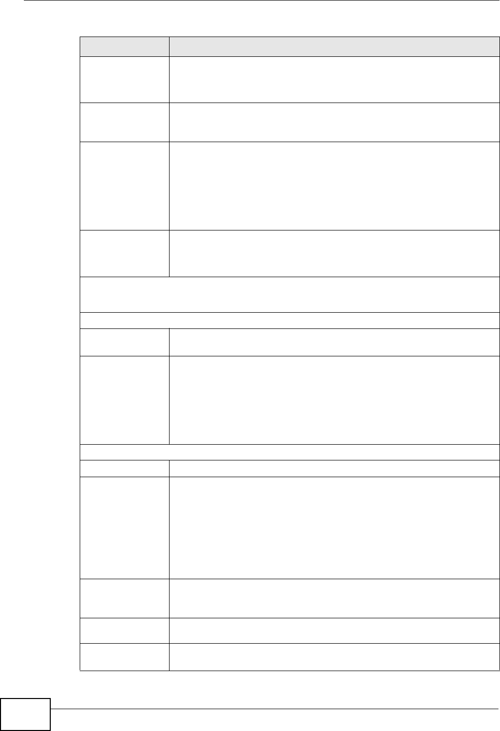
Chapter 10 Quality of Service (QoS)
P-2612HNU(L)-FxF User’s Guide
192
Classification
Order
Select an existing number for where you want to put this classifier to
move the classifier to the number you selected after clicking Apply.
Select Last to put this rule in the back of the classifier list.
Forward to
Interface
Select a WAN interface through which traffic of this class will be
forwarded out. If you select Unchange, the ZyXEL Device forward
traffic of this class according to the default routing table.
DSCP Mark This field is available only when you select the Ether Type check box
in Criteria Configuration-Basic section.
If you select Mark, enter a DSCP value with which the ZyXEL Device
replaces the DSCP field in the packets.
If you select Unchange, the ZyXEL Device keep the DSCP field in the
packets.
To Queue Select a queue that applies to this class.
You should have configured a queue in the Queue Setup screen
already.
Criteria Configuration
Use the following fields to configure the criteria for traffic classification.
Basic
From Interface Select whether the traffic class comes from the LAN or a wireless
interface.
Ether Type Select a predefined application to configure a class for the matched
traffic.
If you select IP, you also need to configure source or destination MAC
address, IP address, DHCP options, DSCP value or the protocol type.
If you select 8021Q, you can configure an 802.1p priority level and
VLAN ID in the Others section.
Source
MAC Address Select the check box and enter the source MAC address of the packet.
MAC Mask Type the mask for the specified MAC address to determine which bits
a packet’s MAC address should match.
Enter “f” for each bit of the specified source MAC address that the
traffic’s MAC address should match. Enter “0“ for the bit(s) of the
matched traffic’s MAC address, which can be of any hexadecimal
character(s). For example, if you set the MAC address to
00:13:49:00:00:00 and the mask to ff:ff:ff:00:00:00, a packet with a
MAC address of 00:13:49:12:34:56 matches this criteria.
IP Address Select the check box and enter the source IP address in dotted
decimal notation. A blank source IP address means any source IP
address.
IP Subnet
Mask Enter the source subnet mask.
Port Range If you select TCP or UDP in the IP Protocol field, select the check
box and enter the port number(s) of the source.
Table 41 Class Setup: Add/Edit (continued)
LABEL DESCRIPTION
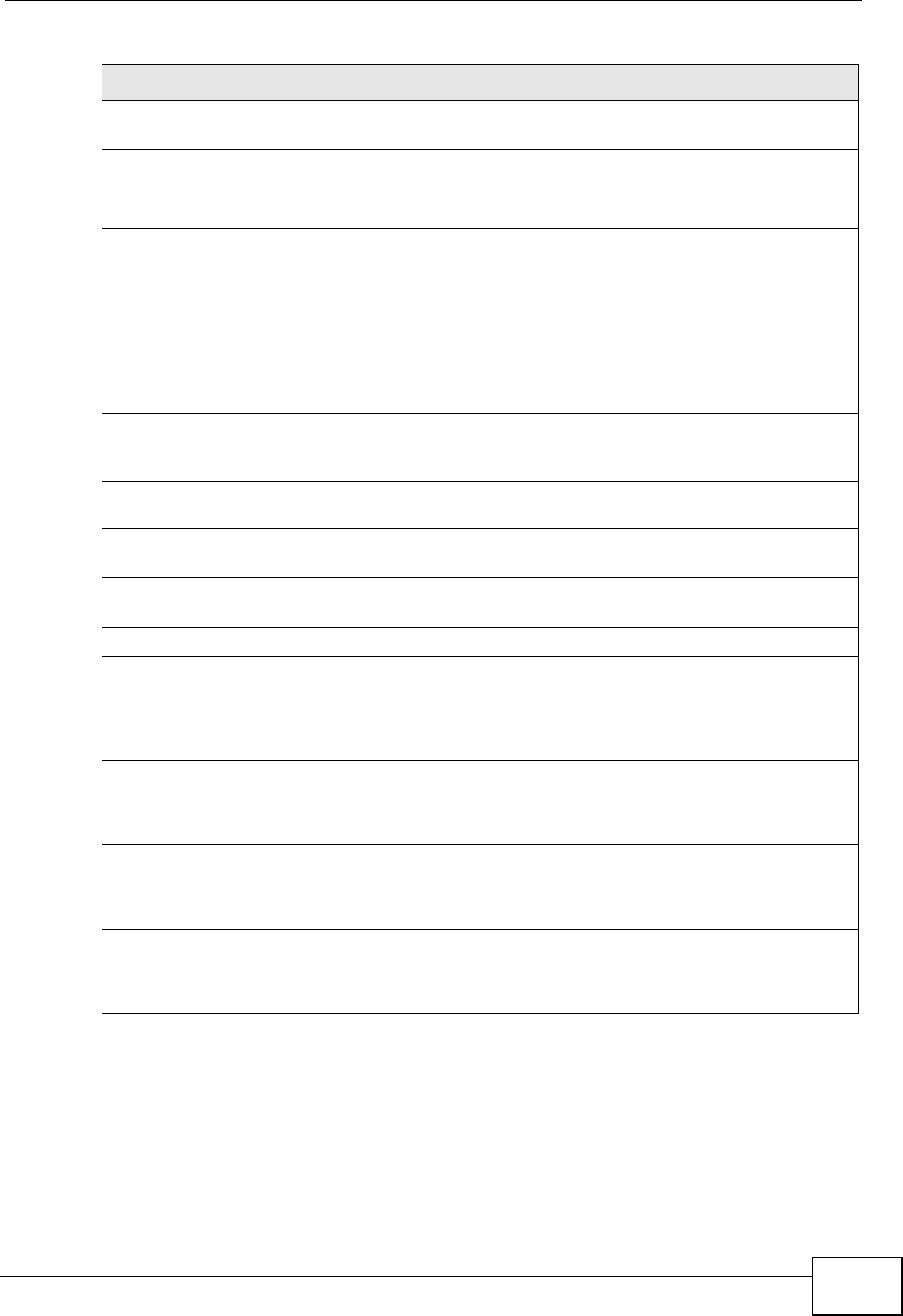
Chapter 10 Quality of Service (QoS)
P-2612HNU(L)-FxF User’s Guide 193
Exclude Select this option to exclude the packets that match the specified
criteria from this classifier.
Destination
MAC Address Select the check box and enter the destination MAC address of the
packet.
MAC Mask Type the mask for the specified MAC address to determine which bits
a packet’s MAC address should match.
Enter “f” for each bit of the specified source MAC address that the
traffic’s MAC address should match. Enter “0“ for the bit(s) of the
matched traffic’s MAC address, which can be of any hexadecimal
character(s). For example, if you set the MAC address to
00:13:49:00:00:00 and the mask to ff:ff:ff:00:00:00, a packet with a
MAC address of 00:13:49:12:34:56 matches this criteria.
IP Address Select the check box and enter the destination IP address in dotted
decimal notation. A blank source IP address means any source IP
address.
IP Subnet
Mask Enter the destination subnet mask.
Port Range If you select TCP or UDP in the IP Protocol field, select the check
box and enter the port number(s) of the source.
Exclude Select this option to exclude the packets that match the specified
criteria from this classifier.
Others
IP Protocol This field is available only when you select IP in the Ether Type field.
Select this option and select the protocol (service type) from TCP or
UDP. If you select User defined, enter the protocol (service type)
number.
IP Packet
Length This field is available only when you select IP in the Ether Type field.
Select this option and enter the minimum and maximum packet
length (from 46 to 1504) in the fields provided.
DSCP This field is available only when you select IP in the Ether Type field.
Select this option and specify a DSCP (DiffServ Code Point) number
between 0 and 63 in the field provided.
TCP ACK This field is available only when you select IP in the Ether Type field.
If you select this option, the matched TCP packets must contain the
ACK (Acknowledge) flag.
Table 41 Class Setup: Add/Edit (continued)
LABEL DESCRIPTION
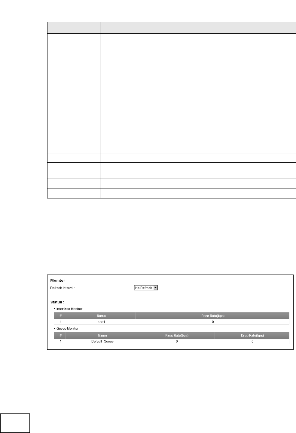
Chapter 10 Quality of Service (QoS)
P-2612HNU(L)-FxF User’s Guide
194
10.5 The QoS Monitor Screen
To view the ZyXEL Device’s QoS packet statistics, click Network Setting > QoS
> Monitor. The screen appears as shown.
Figure 74 Network Setting > QoS > Monitor
DHCP This field is available only when you select IP in the Ether Type field,
and UDP in the IP Protocol field.
Select this option and select a DHCP option.
If you select Vendor Class ID (DHCP Option 60), enter the Class
ID of the matched traffic, such as the type of the hardware or
firmware.
If you select ClientID (DHCP Option 61), enter the Type of the
matched traffic and Client ID of the DHCP client.
If you select User Class ID (DHCP Option 77), enter the User
Class Data, which is a string that identifies the user’s category or
application type in the matched DHCP packets.
If you select VendorSpecificIntro (DHCP Option 125), enter the
Enterprise Number of the software of the matched traffic and
Vendor Class Data used by all the DHCP clients.
Service Select the service classification of the traffic.
Exclude Select this option to exclude the packets that match the specified
criteria from this classifier.
Apply Click Apply to save your changes.
Back Click Back to return to the previous screen without saving.
Table 41 Class Setup: Add/Edit (continued)
LABEL DESCRIPTION
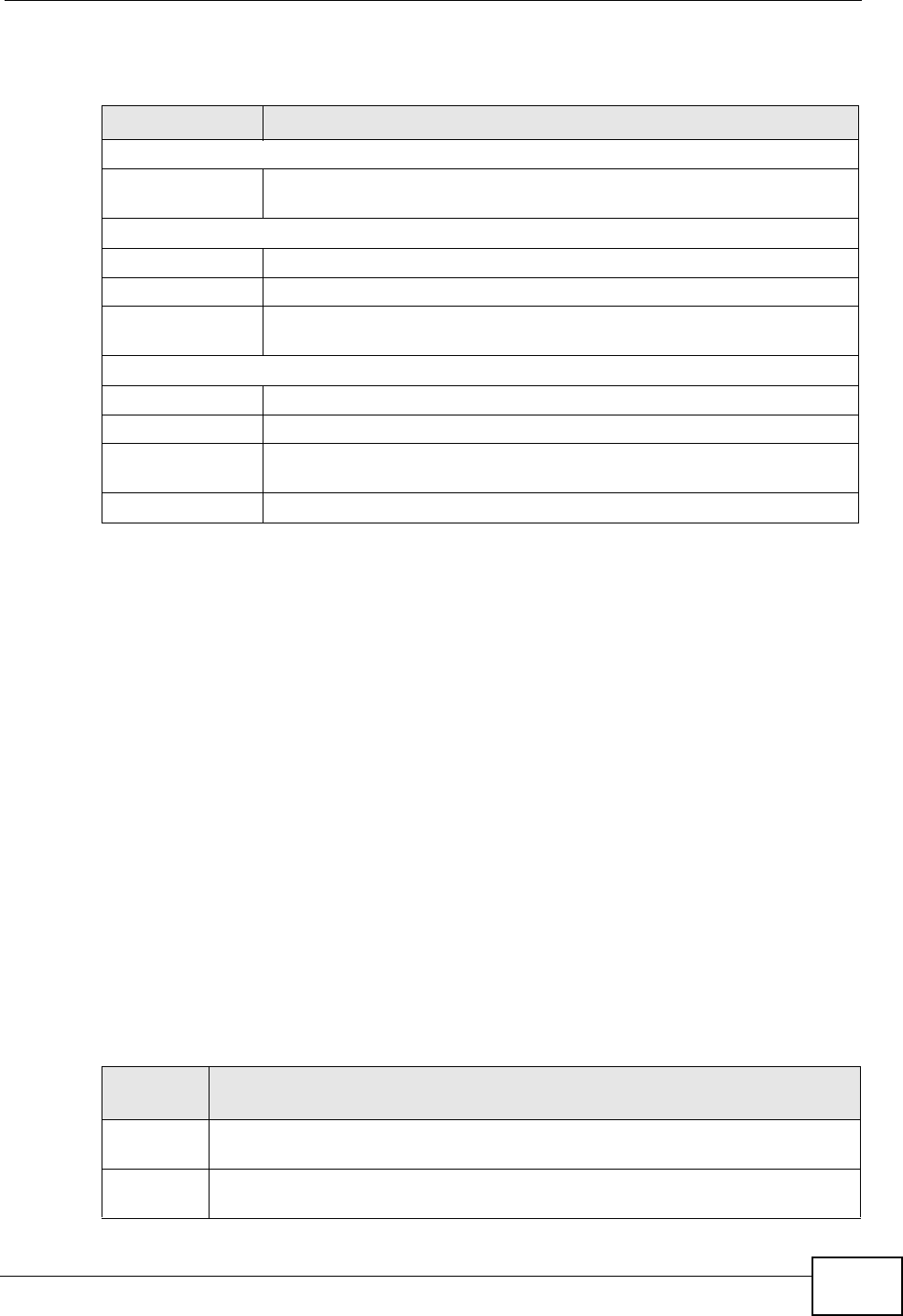
Chapter 10 Quality of Service (QoS)
P-2612HNU(L)-FxF User’s Guide 195
The following table describes the labels in this screen.
10.6 QoS Technical Reference
This section provides some technical background information about the topics
covered in this chapter.
10.6.1 IEEE 802.1Q Tag
The IEEE 802.1Q standard defines an explicit VLAN tag in the MAC header to
identify the VLAN membership of a frame across bridges. A VLAN tag includes the
12-bit VLAN ID and 3-bit user priority. The VLAN ID associates a frame with a
specific VLAN and provides the information that devices need to process the frame
across the network.
IEEE 802.1p specifies the user priority field and defines up to eight separate traffic
types. The following table describes the traffic types defined in the IEEE 802.1d
standard (which incorporates the 802.1p).
Table 42 Network Setting > QoS > Monitor
LABEL DESCRIPTION
Monitor
Refresh Interval Select how often you want the ZyXEL Device to update this screen.
Select No Refresh to stop refreshing statistics.
Status
# This is the index number of the entry.
Name This shows the name of the WAN interface on the ZyXEL Device.
Pass Rate (bps) This shows how many packets forwarded to this interface are
transmitted successfully.
Queue Monitor
# This is the index number of the entry.
Name This shows the name of the queue.
Pass Rate (bps) This shows how many packets assigned to this queue are transmitted
successfully.
Drop Rate (bps) This shows how many packets assigned to this queue are dropped.
Table 43 IEEE 802.1p Priority Level and Traffic Type
PRIORITY
LEVEL TRAFFIC TYPE
Level 7 Typically used for network control traffic such as router configuration
messages.
Level 6 Typically used for voice traffic that is especially sensitive to jitter (jitter is the
variations in delay).
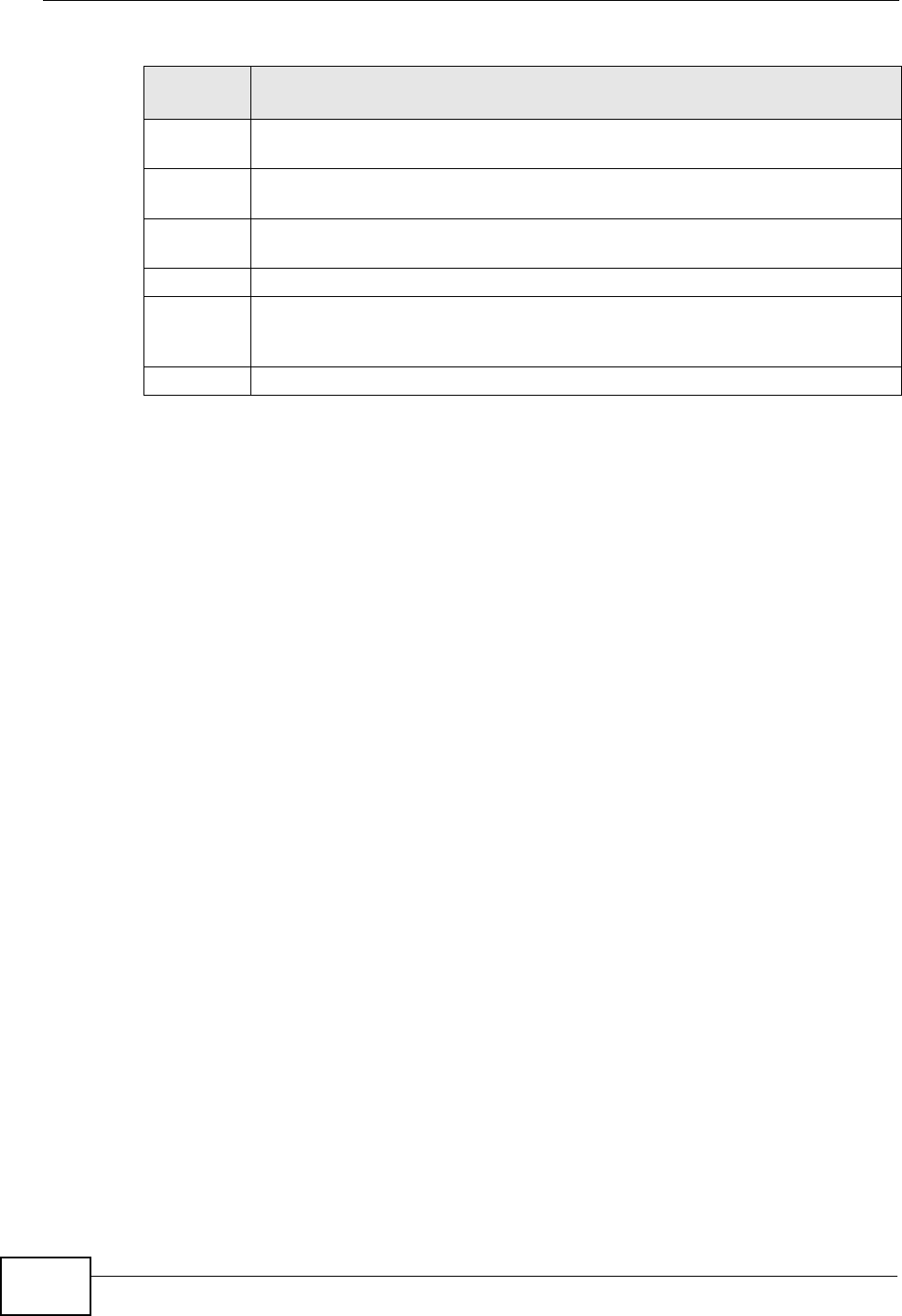
Chapter 10 Quality of Service (QoS)
P-2612HNU(L)-FxF User’s Guide
196
10.6.2 IP Precedence
Similar to IEEE 802.1p prioritization at layer-2, you can use IP precedence to
prioritize packets in a layer-3 network. IP precedence uses three bits of the eight-
bit ToS (Type of Service) field in the IP header. There are eight classes of services
(ranging from zero to seven) in IP precedence. Zero is the lowest priority level and
seven is the highest.
10.6.3 DiffServ
QoS is used to prioritize source-to-destination traffic flows. All packets in the flow
are given the same priority. You can use CoS (class of service) to give different
priorities to different packet types.
DiffServ (Differentiated Services) is a class of service (CoS) model that marks
packets so that they receive specific per-hop treatment at DiffServ-compliant
network devices along the route based on the application types and traffic flow.
Packets are marked with DiffServ Code Points (DSCPs) indicating the level of
service desired. This allows the intermediary DiffServ-compliant network devices
to handle the packets differently depending on the code points without the need to
negotiate paths or remember state information for every flow. In addition,
applications do not have to request a particular service or give advanced notice of
where the traffic is going.
DSCP and Per-Hop Behavior
DiffServ defines a new DS (Differentiated Services) field to replace the Type of
Service (TOS) field in the IP header. The DS field contains a 2-bit unused field and
a 6-bit DSCP field which can define up to 64 service levels. The following figure
illustrates the DS field.
Level 5 Typically used for video that consumes high bandwidth and is sensitive to
jitter.
Level 4 Typically used for controlled load, latency-sensitive traffic such as SNA
(Systems Network Architecture) transactions.
Level 3 Typically used for “excellent effort” or better than best effort and would
include important business traffic that can tolerate some delay.
Level 2 This is for “spare bandwidth”.
Level 1 This is typically used for non-critical “background” traffic such as bulk
transfers that are allowed but that should not affect other applications and
users.
Level 0 Typically used for best-effort traffic.
Table 43 IEEE 802.1p Priority Level and Traffic Type
PRIORITY
LEVEL TRAFFIC TYPE

Chapter 10 Quality of Service (QoS)
P-2612HNU(L)-FxF User’s Guide 197
DSCP is backward compatible with the three precedence bits in the ToS octet so
that non-DiffServ compliant, ToS-enabled network device will not conflict with the
DSCP mapping.
The DSCP value determines the forwarding behavior, the PHB (Per-Hop Behavior),
that each packet gets across the DiffServ network. Based on the marking rule,
different kinds of traffic can be marked for different kinds of forwarding. Resources
can then be allocated according to the DSCP values and the configured policies.
DSCP (6 bits) Unused (2 bits)

Chapter 10 Quality of Service (QoS)
P-2612HNU(L)-FxF User’s Guide
198

P-2612HNU(L)-FxF User’s Guide 199
CHAPTER 11
Network Address Translation
(NAT)
11.1 Overview
NAT (Network Address Translation - NAT, RFC 1631) is the translation of the IP
address of a host in a packet, for example, the source address of an outgoing
packet, used within one network to a different IP address known within another
network.
11.1.1 What You Can Do in this Chapter
• Use the Port Forwarding screen to configure forward incoming service
requests to the server(s) on your local network (Section 11.2 on page 200).
• Use the Sessions screen to limit the number of concurrent NAT sessions each
client can use (Section 11.3 on page 203).
11.1.2 What You Need To Know
The following terms and concepts may help as you read this chapter.
Inside/Outside and Global/Local
Inside/outside denotes where a host is located relative to the ZyXEL Device, for
example, the computers of your subscribers are the inside hosts, while the web
servers on the Internet are the outside hosts.
Global/local denotes the IP address of a host in a packet as the packet traverses a
router, for example, the local address refers to the IP address of a host when the
packet is in the local network, while the global address refers to the IP address of
the host when the same packet is traveling in the WAN side.
NAT
In the simplest form, NAT changes the source IP address in a packet received from
a subscriber (the inside local address) to another (the inside global address)

Chapter 11 Network Address Translation (NAT)
P-2612HNU(L)-FxF User’s Guide
200
before forwarding the packet to the WAN side. When the response comes back,
NAT translates the destination address (the inside global address) back to the
inside local address before forwarding it to the original inside host.
Port Forwarding
A port forwarding set is a list of inside (behind NAT on the LAN) servers, for
example, web or FTP, that you can make visible to the outside world even though
NAT makes your whole inside network appear as a single computer to the outside
world.
Finding Out More
See Section 11.4 on page 204 for advanced technical information on NAT.
11.2 The Port Forwarding Screen
Use the Port Forwarding screen to forward incoming service requests to the
server(s) on your local network.
You may enter a single port number or a range of port numbers to be forwarded,
and the local IP address of the desired server. The port number identifies a
service; for example, web service is on port 80 and FTP on port 21. In some
cases, such as for unknown services or where one server can support more than
one service (for example both FTP and web service), it might be better to specify
a range of port numbers. You can allocate a server IP address that corresponds to
a port or a range of ports.
The most often used port numbers and services are shown in Appendix E on page
381. Please refer to RFC 1700 for further information about port numbers.
Note: Many residential broadband ISP accounts do not allow you to run any server
processes (such as a Web or FTP server) from your location. Your ISP may
periodically check for servers and may suspend your account if it discovers any
active services at your location. If you are unsure, refer to your ISP.
Configuring Servers Behind Port Forwarding (Example)
Let's say you want to assign ports 21-25 to one FTP, Telnet and SMTP server (A in
the example), port 80 to another (B in the example) and assign a default server IP
address of 192.168.1.35 to a third (C in the example). You assign the LAN IP