ZyXEL Communications P2612HNUF1F ADSL2+ VoIP IAD User Manual Manual Part 2
ZyXEL Communications Corporation ADSL2+ VoIP IAD Manual Part 2
Contents
- 1. Manual
- 2. Manual Part 1
- 3. Manual Part 2
Manual Part 2
Chapter 11 Network Address Translation (NAT)
P-2612HNU(L)-FxF User’s Guide 201
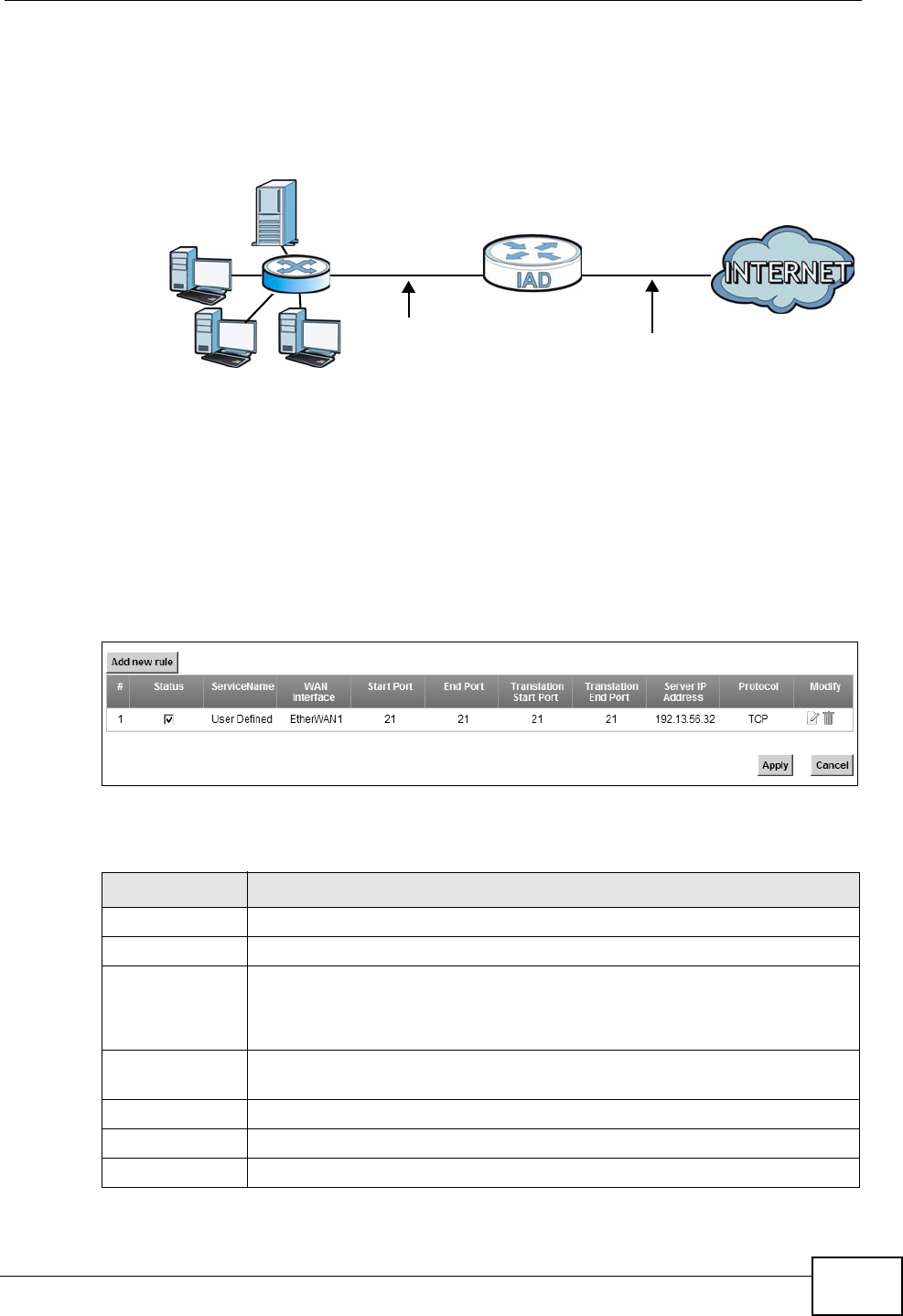
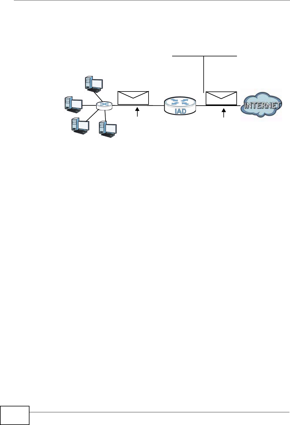
addresses and the ISP assigns the WAN IP address. The NAT network appears as a
single host on the Internet.
Figure 75 Multiple Servers Behind NAT Example
11.2.1 The Port Forwarding Screen
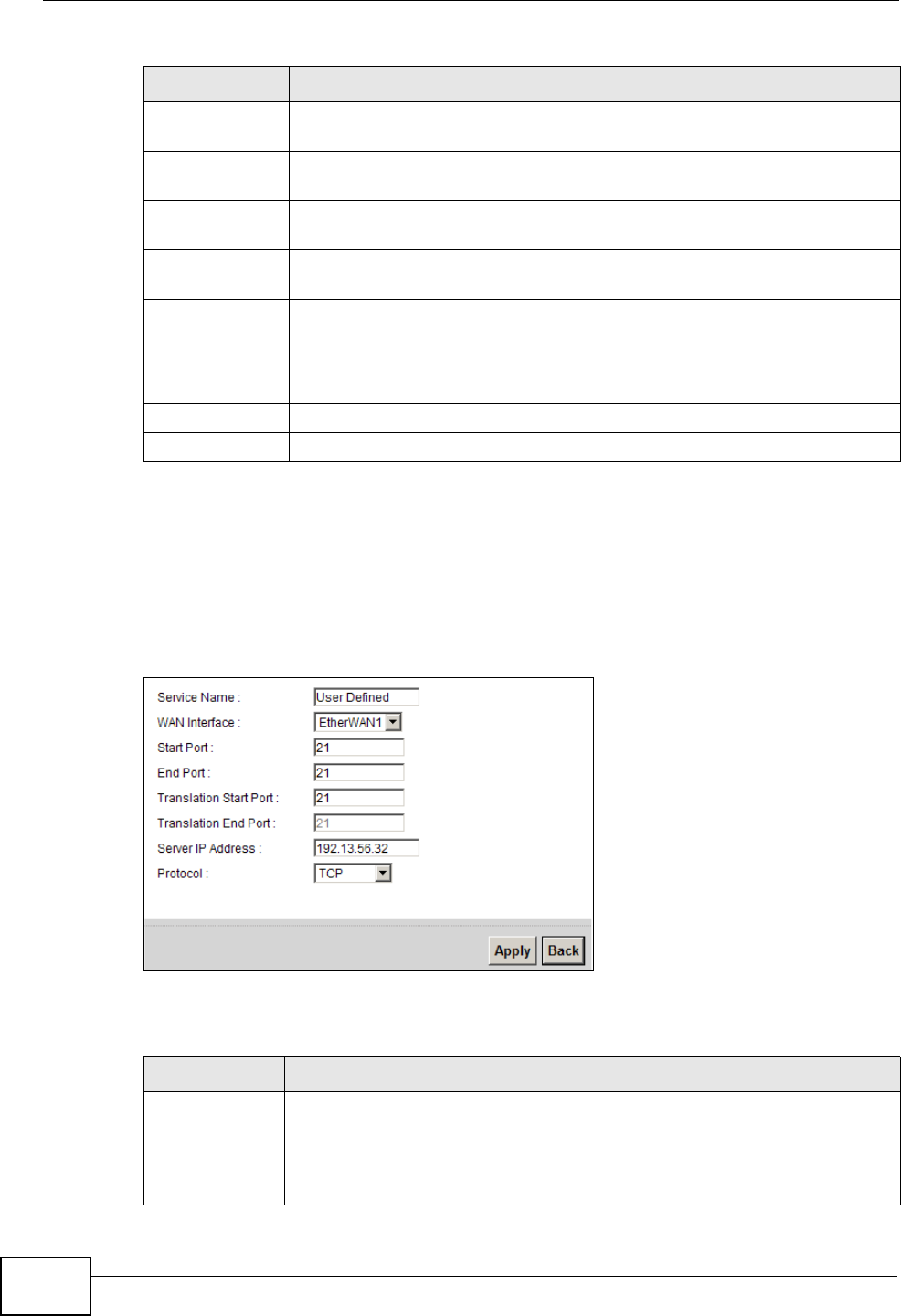
Click Network Setting > NAT to open the Port Forwarding screen.
See Appendix E on page 381 for port numbers commonly used for particular
services.
Figure 76 Network Setting > NAT > Port Forwarding
The following table describes the fields in this screen.
A=192.168.1.33
D=192.168.1.36
C=192.168.1.35
B=192.168.1.34
WAN
LAN
192.168.1.1 IP Address assigned by ISP
Table 44 Network Setting > NAT > Port Forwarding
LABEL DESCRIPTION
Add new rule Click this to add a new port forwarding rule.
# This is the index number of the entry.
Status This field indicates whether the rule is active or not.
Clear the check box to disable the rule. Select the check box to enable
it.
Service Name This is the service’s name. This shows User Defined if you manually
added a service. You can change this by clicking the edit icon.
WAN Interface This shows the WAN interface through which the service is forwarded.
Start Port This is the first external port number that identifies a service.
End Port This is the last external port number that identifies a service.
Chapter 11 Network Address Translation (NAT)
P-2612HNU(L)-FxF User’s Guide
202
11.2.2 The Port Forwarding Edit Screen
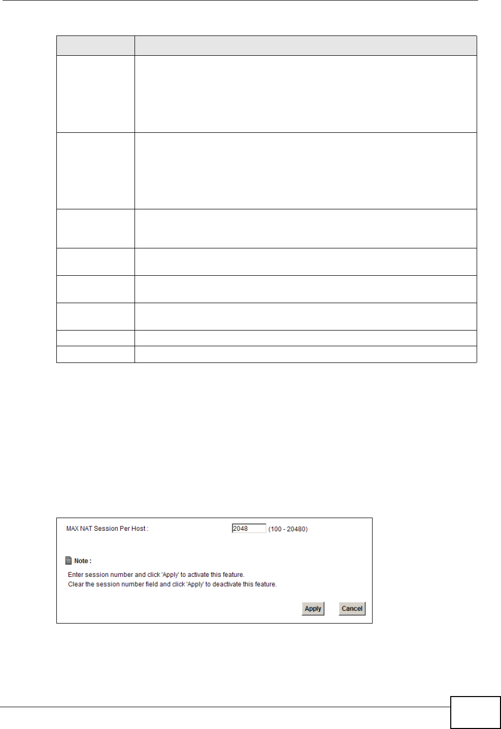
This screen lets you create or edit a port forwarding rule. Click Add new rule in
the Port Forwarding screen or the Edit icon next to an existing rule to open the
following screen.
Figure 77 Port Forwarding: Add/Edit
The following table describes the labels in this screen.
Translation
Start Port
This is the first internal port number that identifies a service.
Translation End
Port
This is the last internal port number that identifies a service.
Server IP
Address
This is the server’s IP address.
Protocol This shows the IP protocol supported by this virtual server, whether it is
TCP, UDP, or TCP/UDP.
Modify Click the Edit icon to edit the port forwarding rule.
Click the Delete icon to delete an existing port forwarding rule. Note
that subsequent address mapping rules move up by one when you take
this action.
Apply Click Apply to save your changes.
Cancel Click Cancel to restore your previously saved settings.
Table 44 Network Setting > NAT > Port Forwarding (continued)
LABEL DESCRIPTION
Table 45 Port Forwarding: Add/Edit
LABEL DESCRIPTION
Service Name Enter a name to identify this rule using keyboard characters (A-Z, a-z, 1-
2 and so on).
WAN Interface Select the WAN interface through which the service is forwarded.
You must have already configured a WAN connection with NAT enabled.
Chapter 11 Network Address Translation (NAT)
P-2612HNU(L)-FxF User’s Guide 203
11.3 The Sessions Screen
Use the Sessions screen to limit the number of concurrent NAT sessions each
client can use.
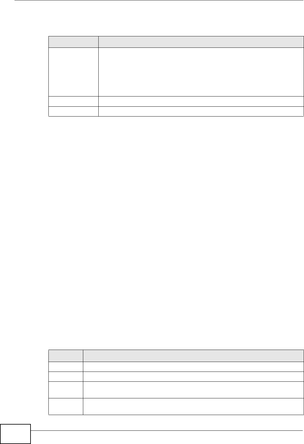
Click Network Setting > NAT > Sessions to display the following screen.
Figure 78 Network Setting > NAT > Sessions
Start Port Enter the original destination port for the packets.
To forward only one port, enter the port number again in the External
End Port field.
To forward a series of ports, enter the start port number here and the
end port number in the External End Port field.
End Port Enter the last port of the original destination port range.
To forward only one port, enter the port number in the External Start
Port field above and then enter it again in this field.
To forward a series of ports, enter the last port number in a series that
begins with the port number in the External Start Port field above.
Translation
Start Port
This shows the port number to which you want the ZyXEL Device to
translate the incoming port. For a range of ports, enter the first number
of the range to which you want the incoming ports translated.
Translation End
Port
This shows the last port of the translated port range.
Server IP
Address
Enter the inside IP address of the virtual server here.
Protocol Type Select the protocol supported by this virtual server. Choices are TCP,
UDP, or TCP/UDP.
Apply Click Apply to save your changes.
Back Click Back to return to the previous screen without saving.
Table 45 Port Forwarding: Add/Edit (continued)
LABEL DESCRIPTION
Chapter 11 Network Address Translation (NAT)
P-2612HNU(L)-FxF User’s Guide
204
The following table describes the fields in this screen.
11.4 Technical Reference
This section provides some technical background information about the topics
covered in this chapter.
11.4.1 NAT Definitions
Inside/outside denotes where a host is located relative to the ZyXEL Device, for
example, the computers of your subscribers are the inside hosts, while the web
servers on the Internet are the outside hosts.
Global/local denotes the IP address of a host in a packet as the packet traverses a
router, for example, the local address refers to the IP address of a host when the
packet is in the local network, while the global address refers to the IP address of
the host when the same packet is traveling in the WAN side.
Note that inside/outside refers to the location of a host, while global/local refers to
the IP address of a host used in a packet. Thus, an inside local address (ILA) is the
IP address of an inside host in a packet when the packet is still in the local
network, while an inside global address (IGA) is the IP address of the same inside
host when the packet is on the WAN side. The following table summarizes this
information.
Table 46 Network Setting > NAT > Sessions
LABEL DESCRIPTION
MAX NAT
Session
Use this field to set a common limit to the number of concurrent NAT
sessions each client computer can have.
If only a few clients use peer to peer applications, you can raise this
number to improve their performance. With heavy peer to peer
application use, lower this number to ensure no single client uses too
many of the available NAT sessions.
Apply Click Apply to save your changes.
Cancel Click Cancel to restore your previously saved settings.
Table 47 NAT Definitions
ITEM DESCRIPTION
Inside This refers to the host on the LAN.
Outside This refers to the host on the WAN.
Local This refers to the packet address (source or destination) as the packet travels
on the LAN.
Global This refers to the packet address (source or destination) as the packet travels
on the WAN.

Chapter 11 Network Address Translation (NAT)
P-2612HNU(L)-FxF User’s Guide 205
NAT never changes the IP address (either local or global) of an outside host.
11.4.2 What NAT Does
In the simplest form, NAT changes the source IP address in a packet received from
a subscriber (the inside local address) to another (the inside global address)
before forwarding the packet to the WAN side. When the response comes back,
NAT translates the destination address (the inside global address) back to the
inside local address before forwarding it to the original inside host. Note that the
IP address (either local or global) of an outside host is never changed.
The global IP addresses for the inside hosts can be either static or dynamically
assigned by the ISP. In addition, you can designate servers, for example, a web
server and a Telnet server, on your local network and make them accessible to the
outside world. If you do not define any servers, NAT offers the additional benefit of
firewall protection. With no servers defined, your ZyXEL Device filters out all
incoming inquiries, thus preventing intruders from probing your network. For
more information on IP address translation, refer to RFC 1631, The IP Network
Address Translator (NAT).
11.4.3 How NAT Works
Each packet has two addresses – a source address and a destination address. For
outgoing packets, the ILA (Inside Local Address) is the source address on the LAN,
and the IGA (Inside Global Address) is the source address on the WAN. For
incoming packets, the ILA is the destination address on the LAN, and the IGA is
the destination address on the WAN. NAT maps private (local) IP addresses to
globally unique ones required for communication with hosts on other networks. It
replaces the original IP source address (and TCP or UDP source port numbers for
Many-to-One and Many-to-Many Overload NAT mapping) in each packet and then
forwards it to the Internet. The ZyXEL Device keeps track of the original addresses
Chapter 11 Network Address Translation (NAT)
P-2612HNU(L)-FxF User’s Guide
206
and port numbers so incoming reply packets can have their original values
restored. The following figure illustrates this.
Figure 79 How NAT Works
192.168.1.13
192.168.1.10
192.168.1.11
192.168.1.12 SA
192.168.1.10
SA
IGA1
Inside Local
IP Address
192.168.1.10
192.168.1.11
192.168.1.12
192.168.1.13
Inside Global
IP Address
IGA 1
IGA 2
IGA 3
IGA 4
NAT Table
WAN
LAN
Inside Local
Address (ILA)
Inside Global
Address (IGA)

P-2612HNU(L)-FxF User’s Guide 207
CHAPTER 12
Dynamic DNS
12.1 Overview
This chapter discusses how to configure your ZyXEL Device to use Dynamic DNS.
Dynamic DNS allows you to update your current dynamic IP address with one or
many dynamic DNS services so that anyone can contact you (in applications such
as NetMeeting and CU-SeeMe). You can also access your FTP server or Web site on
your own computer using a domain name (for instance myhost.dhs.org, where
myhost is a name of your choice) that will never change instead of using an IP
address that changes each time you reconnect. Your friends or relatives will
always be able to call you even if they don't know your IP address.
First of all, you need to have registered a dynamic DNS account with
www.dyndns.org. This is for people with a dynamic IP from their ISP or DHCP
server that would still like to have a domain name. The Dynamic DNS service
provider will give you a password or key.
12.1.1 What You Need To Know
DYNDNS Wildcard
Enabling the wildcard feature for your host causes *.yourhost.dyndns.org to be
aliased to the same IP address as yourhost.dyndns.org. This feature is useful if
you want to be able to use, for example, www.yourhost.dyndns.org and still reach
your hostname.
If you have a private WAN IP address, then you cannot use Dynamic DNS.
Chapter 12 Dynamic DNS
P-2612HNU(L)-FxF User’s Guide
208
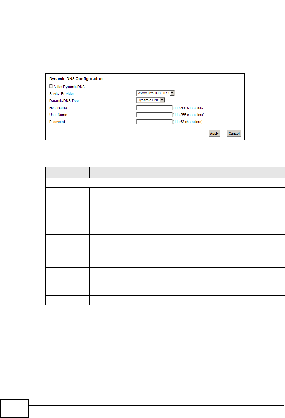
12.2 The Dynamic DNS Screen
Use the Dynamic DNS screen to enable DDNS and configure the DDNS settings
on the ZyXEL Device. To change your ZyXEL Device’s DDNS, click Network
Setting > DNS. The screen appears as shown.
Figure 80 Network Setting > DNS
The following table describes the fields in this screen.
Table 48 Network Setting > DNS
LABEL DESCRIPTION
Dynamic DNS Configuration
Active
Dynamic DNS
Select this check box to use dynamic DNS.
Service
Provider
Select the name of your Dynamic DNS service provider.
Dynamic DNS
Type
Select the type of service that you are registered for from your Dynamic
DNS service provider.
Host Name Type the domain name assigned to your ZyXEL Device by your Dynamic
DNS provider.
You can specify up to two host names in the field separated by a comma
(",").
User Name Type your user name.
Password Type the password assigned to you.
Apply Click Apply to save your changes.
Cancel Click Cancel to restore your previously saved settings.
P-2612HNU(L)-FxF User’s Guide 209
CHAPTER 13
Firewall
13.1 Overview
Use the ZyXEL Device firewall screens to enable and configure the firewall that
protects your ZyXEL Device and network from attacks by hackers on the Internet
and control access to it. By default the firewall:
• allows traffic that originates from your LAN and WLAN computers to go to all
other networks.
• blocks traffic that originates on other networks from going to the LAN and
WLAN.
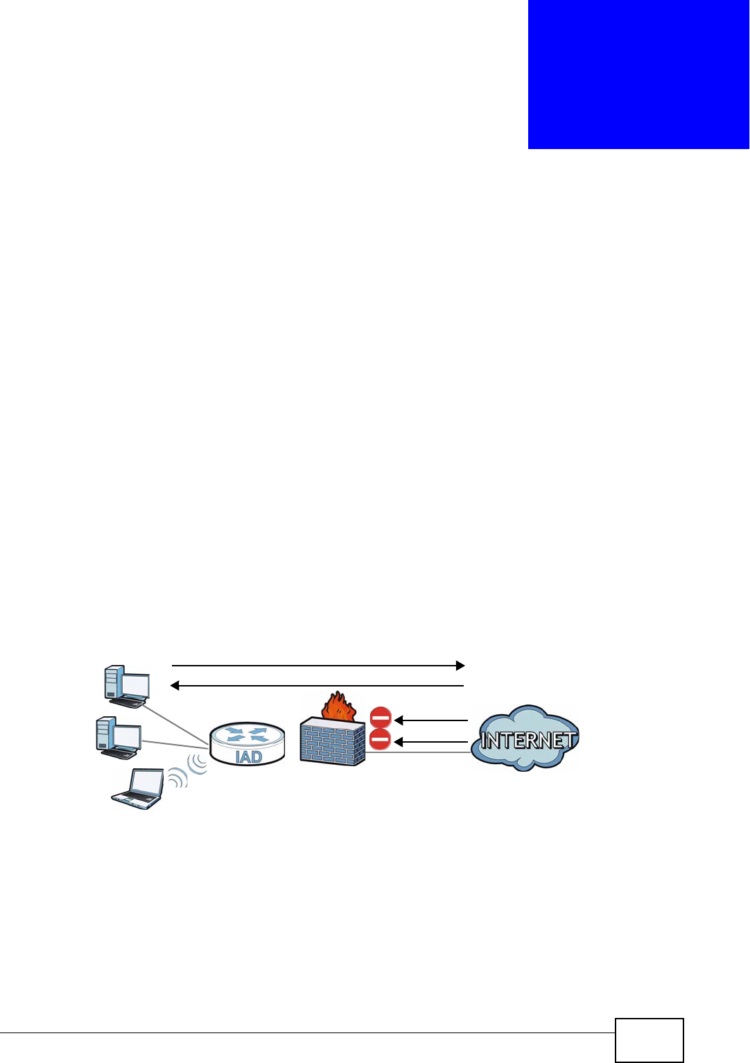
The following figure illustrates the default firewall action. User A can initiate an IM
(Instant Messaging) session from the LAN to the WAN (1). Return traffic for this
session is also allowed (2). However other traffic initiated from the WAN is blocked
(3 and 4).
Figure 81 Default Firewall Action
13.1.1 What You Can Do in this Chapter
• Use the General screen to enable or disable the ZyXEL Device’s firewall
(Section 13.2 on page 211).
• Use the Services screen to view the configured firewall rules and add, edit or
remove a firewall rule (Section 13.3 on page 211).
WAN
LAN
3
4
1
2
A

Chapter 13 Firewall
P-2612HNU(L)-FxF User’s Guide
210
13.1.2 What You Need to Know
Firewall
The ZyXEL Device’s firewall feature physically separates the LAN/WLAN and the
WAN and acts as a secure gateway for all data passing between the networks.
It is designed to protect against Denial of Service (DoS) attacks when activated.
The ZyXEL Device's purpose is to allow a private Local Area Network (LAN) to be
securely connected to the Internet. The ZyXEL Device can be used to prevent
theft, destruction and modification of data, as well as log events, which may be
important to the security of your network.
The ZyXEL Device is installed between the LAN/WLAN and a broadband modem
connecting to the Internet. This allows it to act as a secure gateway for all data
passing between the Internet and the LAN.
The ZyXEL Device has one Ethernet WAN port and four Ethernet LAN ports, which
are used to physically separate the network into two areas.The WAN (Wide Area
Network) port attaches to the broadband (cable or DSL) modem to the Internet.
The LAN (Local Area Network) port attaches to a network of computers, which
needs security from the outside world. These computers will have access to
Internet services such as e-mail, FTP and the World Wide Web. However, "inbound
access" is not allowed (by default) unless the remote host is authorized to use a
specific service.
ICMP
Internet Control Message Protocol (ICMP) is a message control and error-reporting
protocol between a host server and a gateway to the Internet. ICMP uses Internet
Protocol (IP) datagrams, but the messages are processed by the TCP/IP software
and directly apparent to the application user.
Finding Out More
See Section 13.4 on page 213 for advanced technical information on firewall.
Chapter 13 Firewall
P-2612HNU(L)-FxF User’s Guide 211
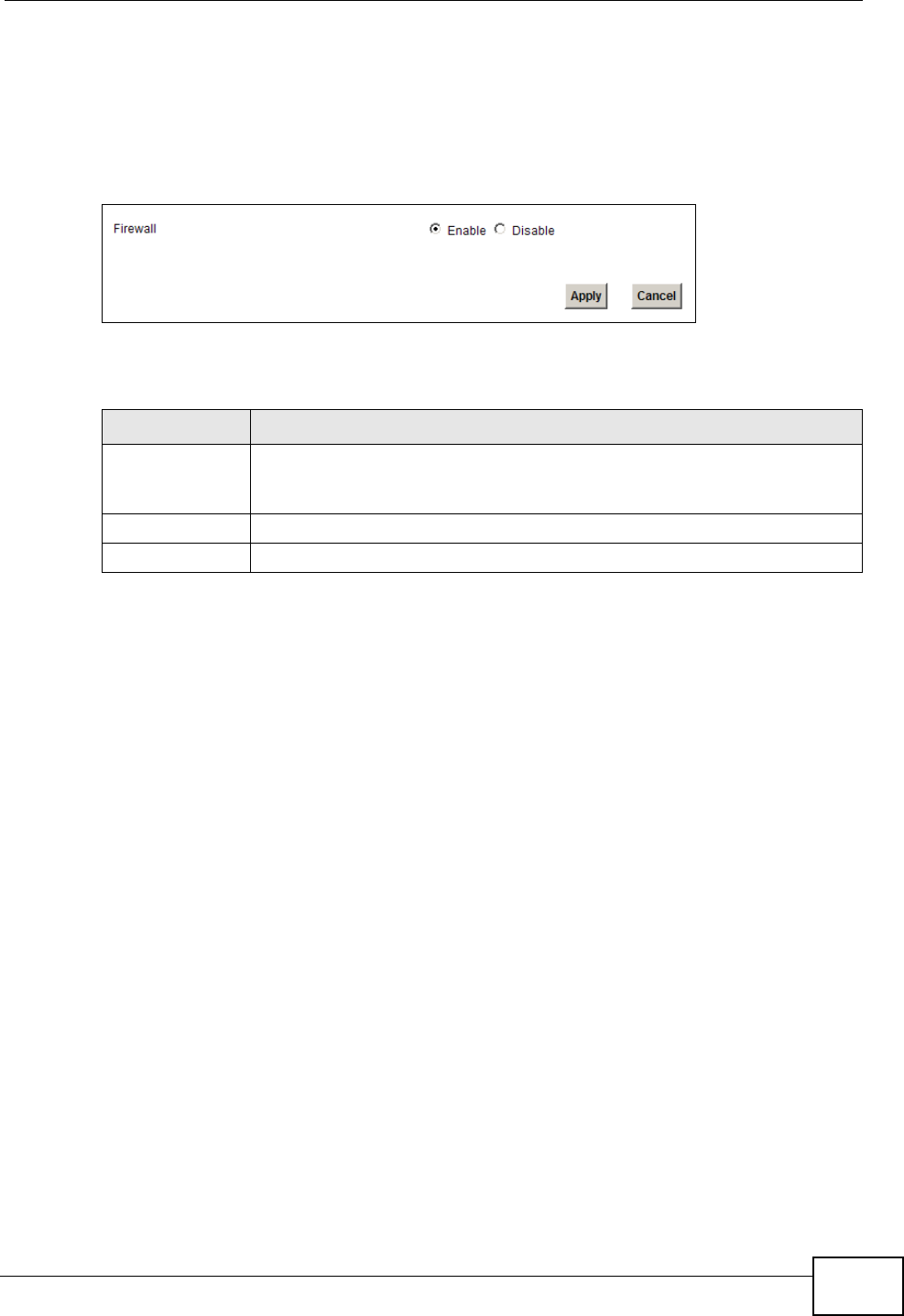
13.2 The General Screen
Use this screen to enable or disable the ZyXEL Device’s firewall. Click Security >
Firewall to open the General screen.
Figure 82 Security > Firewall > General
The following table describes the labels in this screen.
13.3 The Services Screen
Use this screen to enable service blocking and to maintain the list of services you
want to block. To access this screen, click Security > Firewall > Services.
Table 49 Security > Firewall > General
LABEL DESCRIPTION
Firewall Select Enable to activate the firewall. The ZyXEL Device performs
access control and protects against Denial of Service (DoS) attacks
when the firewall is activated.
Apply Click Apply to save your changes.
Cancel Click Cancel to restore your previously saved settings.
Chapter 13 Firewall
P-2612HNU(L)-FxF User’s Guide
212
Note: These rules specify which computers on the LAN can access which computers
or services on the WAN.
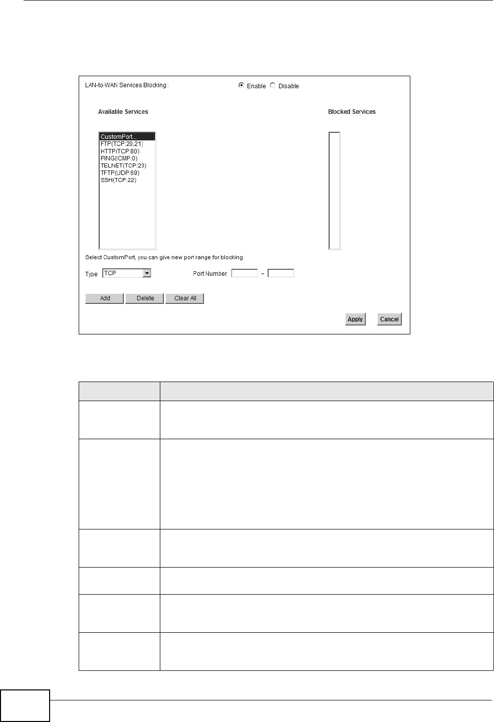
Figure 83 Security > Firewall > Services
Each field is described in the following table.
Table 50 Security > Firewall > Services
LABEL DESCRIPTION
LAN-to-WAN
Services
Blocking
Select Enable to activate service blocking.
Available
Services
This is a list of pre-defined services (destination ports) you may prohibit
your LAN computers from using. Select the port you want to block, and
click Add to add the port to the Blocked Services field.
A custom port is a service that is not available in the pre-defined
Available Services list. You must define it using the Type and Port
Number fields. See Appendix E on page 381 for some examples of
services.
Blocked
Services
This is a list of services (ports) that are inaccessible to computers on
your LAN when service blocking is effective. To remove a service from
this list, select the service, and click Delete.
Type Select TCP, UDP or TCP and UDP, based on which one the custom port
uses.
Port Number Enter the range of port numbers that defines the service. For example,
suppose you want to define the Gnutella service. Select TCP type and
enter a port range of 6345-6349.
Add Click this to add the selected service in Available Services to the
Blocked Services list. Note that the service is blocked immediately
after clicking this.

Chapter 13 Firewall
P-2612HNU(L)-FxF User’s Guide 213
13.4 Firewall Technical Reference
This section provides some technical background information about the topics
covered in this chapter.
13.4.1 Guidelines For Enhancing Security With Your Firewall
1Change the default password via web configurator.
2Think about access control before you connect to the network in any way.
3Limit who can access your ZyXEL Device.
4Don't enable any local service (such as Telnet or FTP) that you don't use. Any
enabled service could present a potential security risk. A determined hacker might
be able to find creative ways to misuse the enabled services to access the firewall
or the network.
5For local services that are enabled, protect against misuse. Protect by configuring
the services to communicate only with specific peers, and protect by configuring
rules to block packets for the services at specific interfaces.
6Keep the firewall in a secured (locked) room.
13.4.2 Security Considerations
Note: Incorrectly configuring the firewall may block valid access or introduce security
risks to the ZyXEL Device and your protected network. Use caution when
creating or deleting firewall rules and test your rules after you configure them.
Consider these security ramifications before creating a rule:
1Does this rule stop LAN users from accessing critical resources on the Internet?
For example, if IRC is blocked, are there users that require this service?
Delete Select a service in the Blocked Services, and click this to remove the
service from the list.
Clear All Click this to remove all the services in the Blocked Services list.
Apply Click Apply to save your changes.
Cancel Click Cancel to restore your previously saved settings.
Table 50 Security > Firewall > Services (continued)
LABEL DESCRIPTION

Chapter 13 Firewall
P-2612HNU(L)-FxF User’s Guide
214
2Is it possible to modify the rule to be more specific? For example, if IRC is blocked
for all users, will a rule that blocks just certain users be more effective?
3Does a rule that allows Internet users access to resources on the LAN create a
security vulnerability? For example, if FTP ports (TCP 20, 21) are allowed from the
Internet to the LAN, Internet users may be able to connect to computers with
running FTP servers.
4Does this rule conflict with any existing rules?
Once these questions have been answered, adding rules is simply a matter of
entering the information into the correct fields in the web configurator screens.

P-2612HNU(L)-FxF User’s Guide 215
CHAPTER 14
MAC Filter
14.1 Overview
This chapter discusses MAC address filtering.
You can configure the ZyXEL Device to permit access to clients based on their MAC
addresses in the MAC Filter screen. This applies to wired and wireless
connections.
14.1.1 What You Need to Know
Every Ethernet device has a unique MAC (Media Access Control) address. The MAC
address is assigned at the factory and consists of six pairs of hexadecimal
characters, for example, 00:A0:C5:00:00:02. You need to know the MAC address
of the devices to configure this screen.
Chapter 14 MAC Filter
P-2612HNU(L)-FxF User’s Guide
216
14.2 The MAC Filter Screen
Use the MAC Filter screen to allow wireless clients access to the ZyXEL Device. To
change your ZyXEL Device’s MAC filter settings, click Security > MAC Filter. The
screen appears as shown.
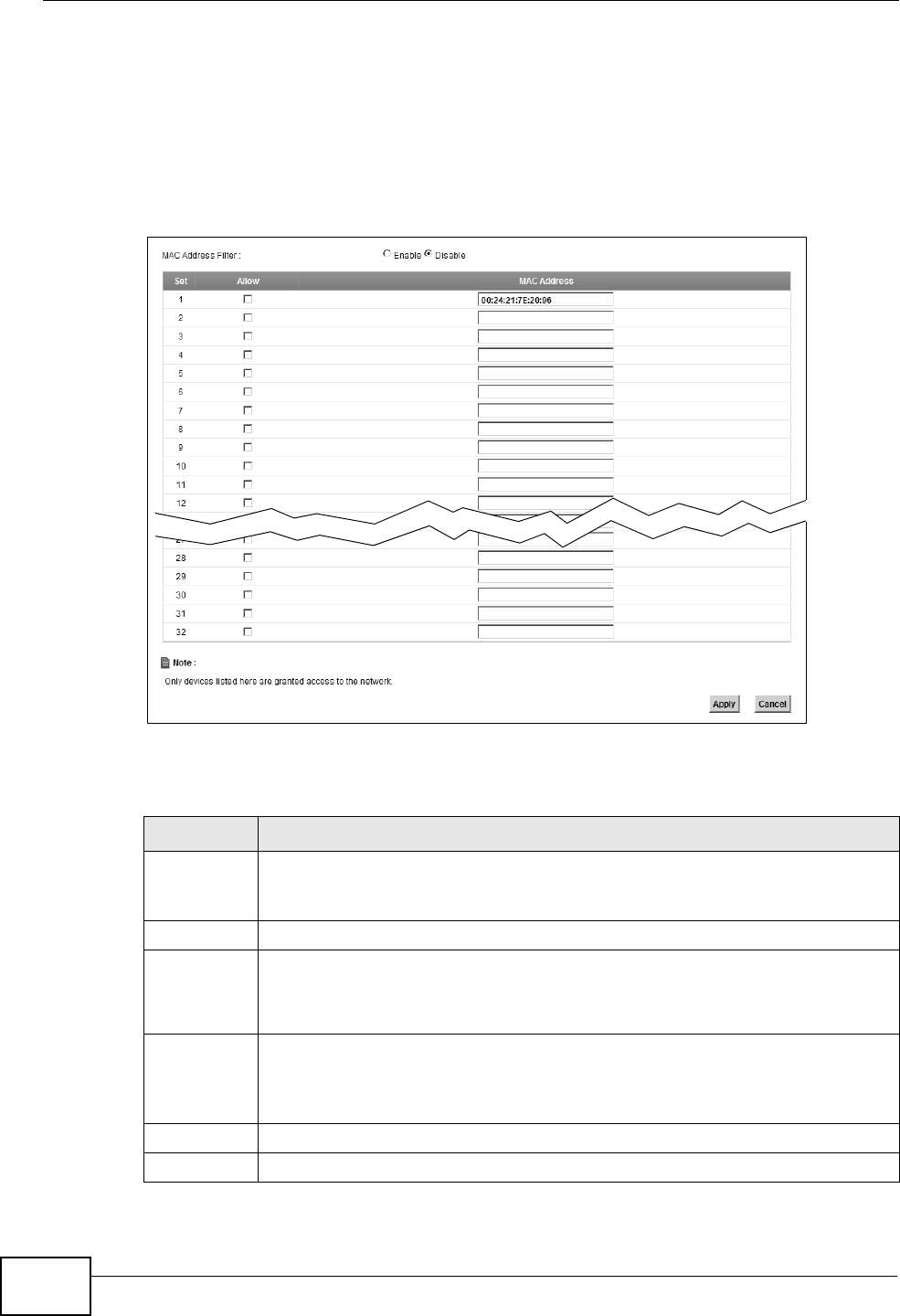
Figure 84 Security > MAC Filter
The following table describes the labels in this menu.
Table 51 Security > MAC Filter
LABEL DESCRIPTION
MAC
Address
Filter
Select Enable to activate MAC address filtering.
Set This is the index number of the MAC address.
Allow Select Allow to permit access to the ZyXEL Device. MAC addresses not
listed will be denied access to the ZyXEL Device.
If you clear this, the MAC Address field for this set clears.
MAC
Address
Enter the MAC addresses of the wireless station that are allowed access to
the ZyXEL Device in these address fields. Enter the MAC addresses in a
valid MAC address format, that is, six hexadecimal character pairs, for
example, 12:34:56:78:9a:bc.
Apply Click Apply to save your changes.
Cancel Click Cancel to restore your previously saved settings.

P-2612HNU(L)-FxF User’s Guide 217
CHAPTER 15
Certificates
15.1 Overview
The ZyXEL Device can use certificates (also called digital IDs) to authenticate
users. Certificates are based on public-private key pairs. A certificate contains the
certificate owner’s identity and public key. Certificates provide a way to exchange
public keys for use in authentication.
15.1.1 What You Can Do in this Chapter
• Use the Local Certificate screens to view and import the ZyXEL Device’s CA-
signed certificates (Section 15.2 on page 220).
• Use the Trusted CA screens to save the certificates of trusted CAs to the ZyXEL
Device. You can also export the certificates to a computer (Section 15.3 on page
222).
15.1.2 What You Need to Know
The following terms and concepts may help as you read this chapter.
Certification Authorities
A Certification Authority (CA) issues certificates and guarantees the identity of
each certificate owner. There are commercial certification authorities like
CyberTrust or VeriSign and government certification authorities.
Public and Private Keys
When using public-key cryptology for authentication, each host has two keys. One
key is public and can be made openly available; the other key is private and must
be kept secure. Public-key encryption in general works as follows.
1Tim wants to send a private message to Jenny. Tim generates a public-private key
pair. What is encrypted with one key can only be decrypted using the other.
2Tim keeps the private key and makes the public key openly available.

Chapter 15 Certificates
P-2612HNU(L)-FxF User’s Guide
218
3Tim uses his private key to encrypt the message and sends it to Jenny.
4Jenny receives the message and uses Tim’s public key to decrypt it.
5Additionally, Jenny uses her own private key to encrypt a message and Tim uses
Jenny’s public key to decrypt the message.
The ZyXEL Device uses certificates based on public-key cryptology to authenticate
users attempting to establish a connection. The method used to secure the data
that you send through an established connection depends on the type of
connection. For example, a VPN tunnel might use the triple DES encryption
algorithm.
The certification authority uses its private key to sign certificates. Anyone can then
use the certification authority’s public key to verify the certificates.
Certification Path
A certification path is the hierarchy of certification authority certificates that
validate a certificate. The ZyXEL Device does not trust a certificate if any
certificate on its path has expired or been revoked.
Certificate Directory Servers
Certification authorities maintain directory servers with databases of valid and
revoked certificates. A directory of certificates that have been revoked before the
scheduled expiration is called a CRL (Certificate Revocation List). The ZyXEL
Device can check a peer’s certificate against a directory server’s list of revoked
certificates. The framework of servers, software, procedures and policies that
handles keys is called PKI (public-key infrastructure).
Advantages of Certificates
Certificates offer the following benefits.
• The ZyXEL Device only has to store the certificates of the certification
authorities that you decide to trust, no matter how many devices you need to
authenticate.
• Key distribution is simple and very secure since you can freely distribute public
keys and you never need to transmit private keys.
Certificate File Formats
The certification authority certificate that you want to import has to be in one of
these file formats:
Chapter 15 Certificates
P-2612HNU(L)-FxF User’s Guide 219
• Binary X.509: This is an ITU-T recommendation that defines the formats for
X.509 certificates.
• PEM (Base-64) encoded X.509: This Privacy Enhanced Mail format uses 64
ASCII characters to convert a binary X.509 certificate into a printable form.
• Binary PKCS#7: This is a standard that defines the general syntax for data
(including digital signatures) that may be encrypted. The ZyXEL Device
currently allows the importation of a PKS#7 file that contains a single
certificate.
• PEM (Base-64) encoded PKCS#7: This Privacy Enhanced Mail (PEM) format uses
64 ASCII characters to convert a binary PKCS#7 certificate into a printable
form.
Note: Be careful not to convert a binary file to text during the transfer process. It is
easy for this to occur since many programs use text files by default.
15.1.3 Verifying a Certificate
Before you import a trusted CA or trusted remote host certificate into the ZyXEL
Device, you should verify that you have the actual certificate. This is especially
true of trusted CA certificates since the ZyXEL Device also trusts any valid
certificate signed by any of the imported trusted CA certificates.
You can use a certificate’s fingerprint to verify it. A certificate’s fingerprint is a
message digest calculated using the MD5 or SHA1 algorithms. The following
procedure describes how to check a certificate’s fingerprint to verify that you have
the actual certificate.
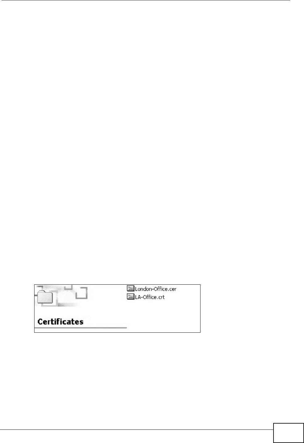
1Browse to where you have the certificate saved on your computer.
2Make sure that the certificate has a “.cer” or “.crt” file name extension.
Figure 85 Certificates on Your Computer
Chapter 15 Certificates
P-2612HNU(L)-FxF User’s Guide
220
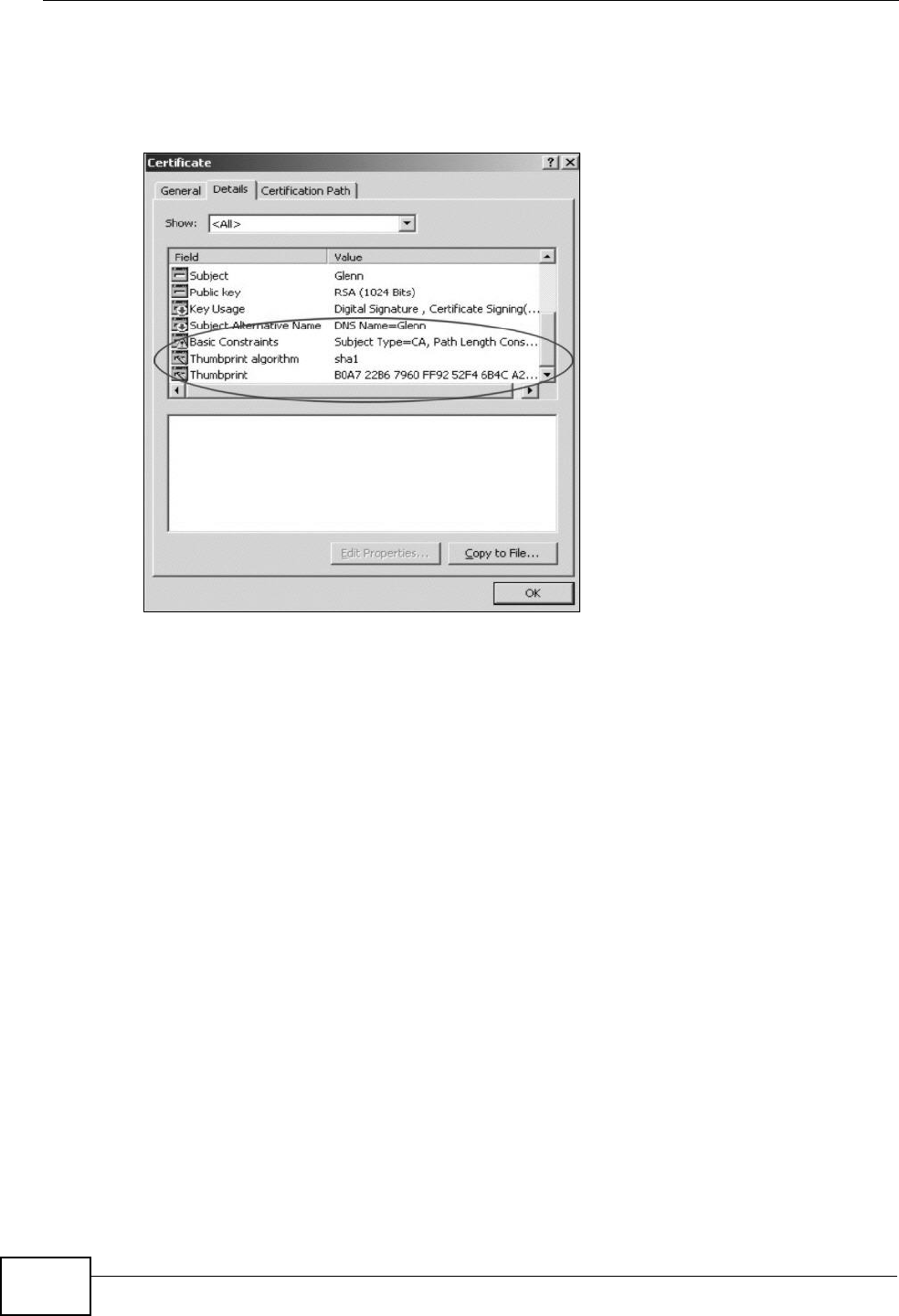
3Double-click the certificate’s icon to open the Certificate window. Click the
Details tab and scroll down to the Thumbprint Algorithm and Thumbprint
fields.
Figure 86 Certificate Details
4Use a secure method to verify that the certificate owner has the same information
in the Thumbprint Algorithm and Thumbprint fields. The secure method may
very based on your situation. Possible examples would be over the telephone or
through an HTTPS connection.
15.2 Local Certificates
Use this screen to view the ZyXEL Device’s summary list of certificates and
certification requests. You can import the following certificates to your ZyXEL
Device:
• Web Server - This certificate secures HTTP connections.
• SIP TLS - This certificate secures VoIP connections.
• SSH/SCP/SFTP - This certificate secures remote connections.
Chapter 15 Certificates
P-2612HNU(L)-FxF User’s Guide 221
Click Security > Certificates to open the Local Certificates screen.
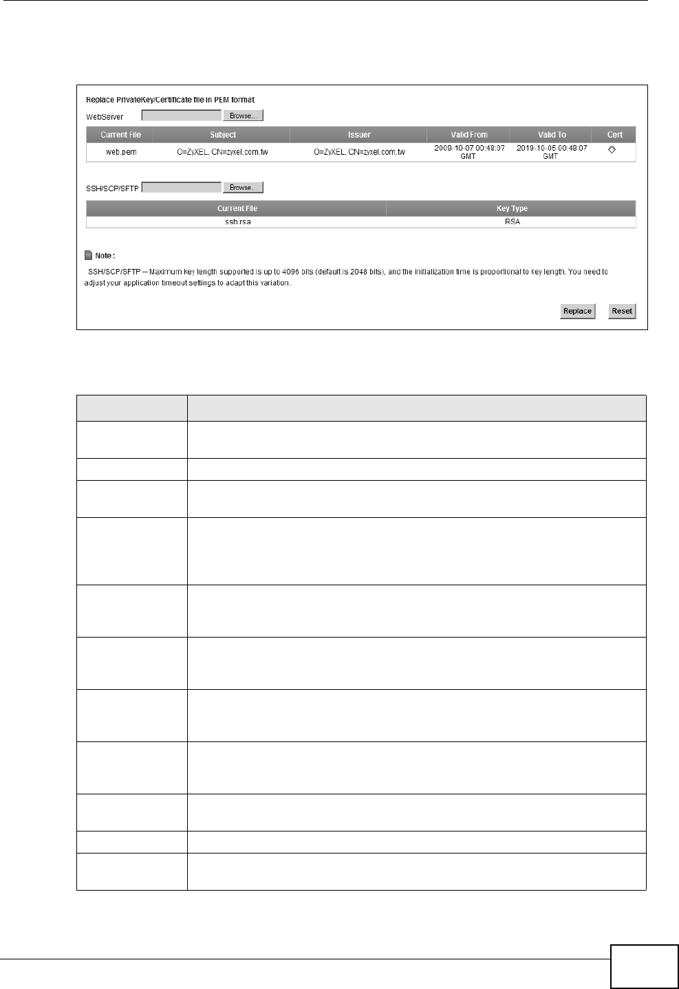
Figure 87 Security > Certificates > Local Certificates
The following table describes the labels in this screen.
Table 52 Security > Certificates > Local Certificates
LABEL DESCRIPTION
Web Server Type in the location of the Web Server certificate file you want to
upload in this field or click Browse to find it.
Browse Click Browse to find the certificate file you want to upload.
Current File This field displays the name used to identify this certificate. It is
recommended that you give each certificate a unique name.
Subject This field displays identifying information about the certificate’s owner,
such as CN (Common Name), OU (Organizational Unit or department),
O (Organization or company) and C (Country). It is recommended that
each certificate have unique subject information.
Issuer This field displays identifying information about the certificate’s issuing
certification authority, such as a common name, organizational unit or
department, organization or company and country.
Valid From This field displays the date that the certificate becomes applicable. The
text displays in red and includes a Not Yet Valid! message if the
certificate has not yet become applicable.
Valid To This field displays the date that the certificate expires. The text displays
in red and includes an Expiring! or Expired! message if the certificate
is about to expire or has already expired.
Cert Click this button and then Save in the File Download screen. The
Save As screen opens, browse to the location that you want to use and
click Save.
SSH/SCP/SFTP Type in the location of the SSH/SCP/SFTP certificate file you want to
upload in this field or click Browse to find it.
Browse Click Browse to find the certificate file you want to upload.
Current File This field displays the name used to identify this certificate. It is
recommended that you give each certificate a unique name.
Chapter 15 Certificates
P-2612HNU(L)-FxF User’s Guide
222
15.3 Trusted CA
Use this screen to view a summary list of certificates of the certification authorities
that you have set the ZyXEL Device to accept as trusted. The ZyXEL Device
accepts any valid certificate signed by a certification authority on this list as being
trustworthy; thus you do not need to import any certificate that is signed by one
of these certification authorities.
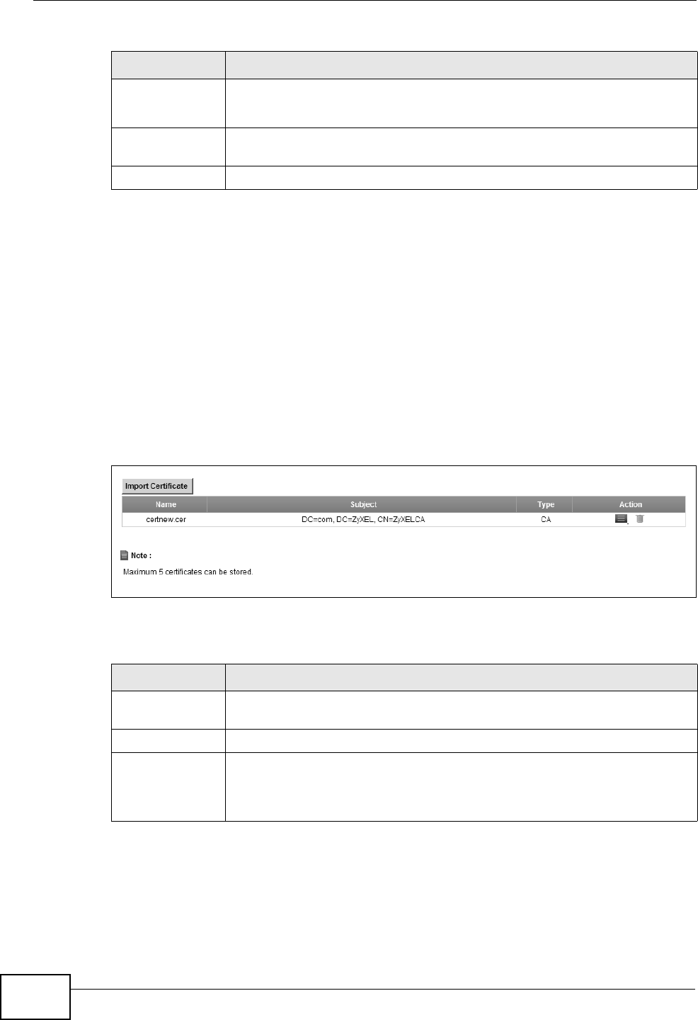
Click Security > Certificates > Trusted CA to open the Trusted CA screen.
Figure 88 Security > Certificates > Trusted CA
The following table describes the labels in this screen.
Key Type This field applies to the SSH/SCP/SFTP certificate.
This shows the file format of the current certificate.
Replace Click this to replace the certificate(s) and save your changes back to the
ZyXEL Device.
Reset Click this to clear your settings.
Table 52 Security > Certificates > Local Certificates (continued)
LABEL DESCRIPTION
Table 53 Security > Certificates > Trusted CA
LABEL DESCRIPTION
Import
Certificate
Click this button to open a screen where you can save the certificate of
a certification authority that you trust to the ZyXEL Device.
Name This field displays the name used to identify this certificate.
Subject This field displays information that identifies the owner of the
certificate, such as Common Name (CN), OU (Organizational Unit or
department), Organization (O), State (ST) and Country (C). It is
recommended that each certificate have unique subject information.
Chapter 15 Certificates
P-2612HNU(L)-FxF User’s Guide 223
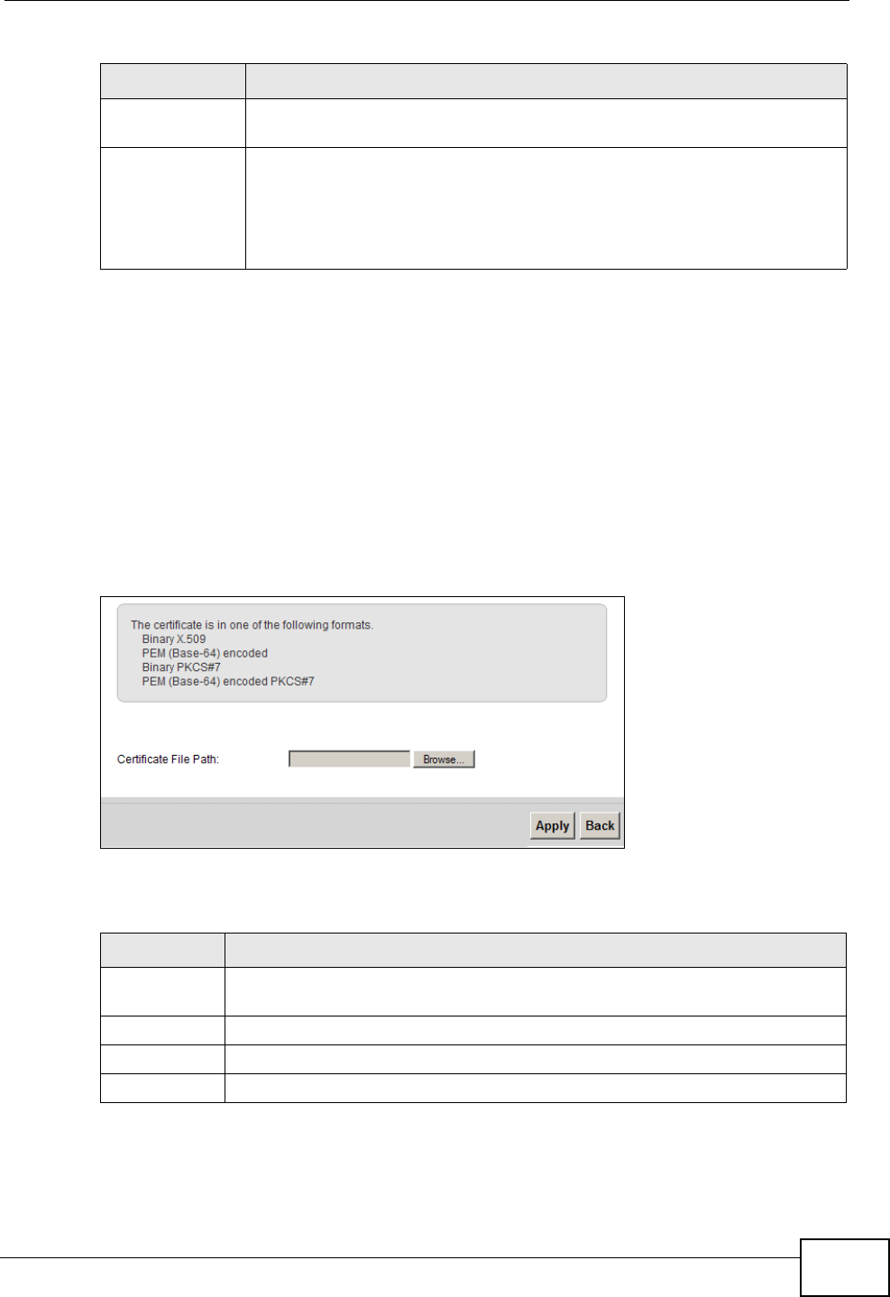
15.4 Trusted CA Import
Click Import Certificate in the Trusted CAs screen to open the Import
Certificate screen. You can save a trusted certification authority’s certificate to
the ZyXEL Device.
Note: You must remove any spaces from the certificate’s filename before you can
import the certificate.
Figure 89 Trusted CA > Import
The following table describes the labels in this screen.
Type This field displays general information about the certificate. ca means
that a Certification Authority signed the certificate.
Action Click the View icon to open a screen with an in-depth list of information
about the certificate (or certification request).
Click the Delete icon to delete the certificate (or certification request).
You cannot delete a certificate that one or more features is configured
to use.
Table 53 Security > Certificates > Trusted CA (continued)
LABEL DESCRIPTION
Table 54 Security > Certificates > Trusted CA > Import
LABEL DESCRIPTION
Certificate
File Path
Type in the location of the file you want to upload in this field or click
Browse to find it.
Browse Click Browse to find the certificate file you want to upload.
Apply Click Apply to save the certificate on the ZyXEL Device.
Back Click Back to return to the previous screen.
Chapter 15 Certificates
P-2612HNU(L)-FxF User’s Guide
224
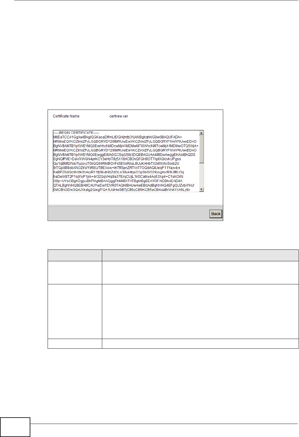
15.5 View Certificate
Use this screen to view in-depth information about the certification authority’s
certificate, change the certificate’s name and set whether or not you want the
ZyXEL Device to check a certification authority’s list of revoked certificates before
trusting a certificate issued by the certification authority.
Click Security > Certificates > Trusted CA to open the Trusted CA screen.
Click the View icon to open the View Certificate screen.
Figure 90 Trusted CA: View
The following table describes the labels in this screen.
Table 55 Trusted CA: View
LABEL DESCRIPTION
Certificate Name This field displays the identifying name of this certificate. If you want
to change the name, type up to 31 characters to identify this key
certificate. You may use any character (not including spaces).
Certificate Detail This read-only text box displays the certificate or certification request
in Privacy Enhanced Mail (PEM) format. PEM uses 64 ASCII characters
to convert the binary certificate into a printable form.
You can copy and paste the certificate into an e-mail to send to
friends or colleagues or you can copy and paste the certificate into a
text editor and save the file on a management computer for later
distribution (via floppy disk for example).
Back Click this to return to the previous screen.

P-2612HNU(L)-FxF User’s Guide 225
CHAPTER 16
VoIP
16.1 Overview
Use this chapter to:
• Connect an analog phone to the ZyXEL Device.
• Make phone calls over the Internet, as well as the regular phone network.
• Configure settings such as speed dial.
• Configure network settings to optimize the voice quality of your phone calls.
16.1.1 What You Can Do in this Chapter
These screens allow you to configure your ZyXEL Device to make phone calls over
the Internet and your regular phone line, and to set up the phones you connect to
the ZyXEL Device.
• Use the SIP Service Provider screen to configure the SIP server information,
QoS for VoIP calls, the numbers for certain phone functions (Section 16.3 on
page 231).
• Use the SIP Account screen to set up information about your SIP account,
control which SIP accounts the phones connected to the ZyXEL Device use and
configure audio settings such as volume levels for the phones connected to the
ZyXEL Device (Section 16.3 on page 231).
• Use the Common screen to configure RFC3262 support on the ZyXEL Device
(Section 16.4 on page 236).
• Use the Phone Device screen to control which SIP accounts the phones
connected to the ZyXEL Device use (Section 16.6 on page 239).
• Use the Region screen to change settings that depend on the country you are
in (Section 16.7 on page 241).
• Use the Call Rule screen to set up shortcuts for dialing frequently-used (VoIP)
phone numbers (Section 16.9 on page 243).
• Use the FXO screen to set up the PSTN line used to make regular phone calls
which do not use the Internet (Section 16.9 on page 243).

Chapter 16 VoIP
P-2612HNU(L)-FxF User’s Guide
226
You don’t necessarily need to use all these screens to set up your account. In fact,
if your service provider did not supply information on a particular field in a screen,
it is usually best to leave it at its default setting.
16.1.2 What You Need to Know
The following terms and concepts may help as you read this chapter.
VoIP
VoIP stands for Voice over IP. IP is the Internet Protocol, which is the message-
carrying standard the Internet runs on. So, Voice over IP is the sending of voice
signals (speech) over the Internet (or another network that uses the Internet
Protocol).
SIP
SIP stands for Session Initiation Protocol. SIP is a signalling standard that lets one
network device (like a computer or the ZyXEL Device) send messages to another.
In VoIP, these messages are about phone calls over the network. For example,
when you dial a number on your ZyXEL Device, it sends a SIP message over the
network asking the other device (the number you dialed) to take part in the call.
SIP Accounts
A SIP account is a type of VoIP account. It is an arrangement with a service
provider that lets you make phone calls over the Internet. When you set the
ZyXEL Device to use your SIP account to make calls, the ZyXEL Device is able to
send all the information about the phone call to your service provider on the
Internet.
Strictly speaking, you don’t need a SIP account. It is possible for one SIP device
(like the ZyXEL Device) to call another without involving a SIP service provider.
However, the networking difficulties involved in doing this make it tremendously
impractical under normal circumstances. Your SIP account provider removes these
difficulties by taking care of the call routing and setup - figuring out how to get
your call to the right place in a way that you and the other person can talk to one
another.
Voice Activity Detection/Silence Suppression
Voice Activity Detection (VAD) detects whether or not speech is present. This lets
the ZyXEL Device reduce the bandwidth that a call uses by not transmitting “silent
packets” when you are not speaking.

Chapter 16 VoIP
P-2612HNU(L)-FxF User’s Guide 227
Comfort Noise Generation
When using VAD, the ZyXEL Device generates comfort noise when the other party
is not speaking. The comfort noise lets you know that the line is still connected as
total silence could easily be mistaken for a lost connection.
Echo Cancellation
G.168 is an ITU-T standard for eliminating the echo caused by the sound of your
voice reverberating in the telephone receiver while you talk.
Use this screen to maintain basic information about each SIP account. You can
also enable and disable each SIP account, configure the volume, echo cancellation
and VAD (Voice Activity Detection) settings for each individual phone port on the
ZyXEL Device.
How to Find Out More
See Chapter 3 on page 37 for a tutorial showing how to set up these screens in an
example scenario.
See Section 16.10 on page 244 for advanced technical information on SIP.
16.1.3 Before You Begin
• Before you can use these screens, you need to have a VoIP account already set
up. If you don’t have one yet, you can sign up with a VoIP service provider over
the Internet.
• You should have the information your VoIP service provider gave you ready,
before you start to configure the ZyXEL Device.
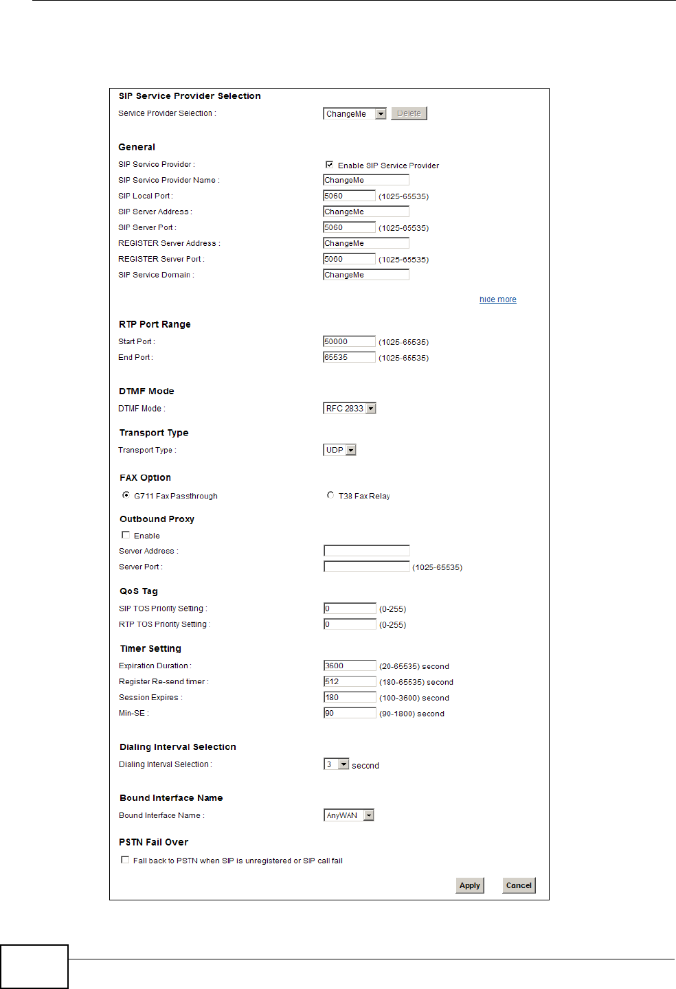
16.2 The SIP Service Provider Screen
Use this screen to configure the SIP server information, QoS for VoIP calls, the
numbers for certain phone functions and dialing plan. Click VoIP > SIP to open
the SIP Service Provider screen.
Note: Click more... to see all the fields in the screen. You don’t necessarily need to
use all these fields to set up your account. Click hide more to see and
configure only the fields needed for this feature.
Chapter 16 VoIP
P-2612HNU(L)-FxF User’s Guide
228
Figure 91 VoIP > SIP > SIP Service Provider
Chapter 16 VoIP
P-2612HNU(L)-FxF User’s Guide 229
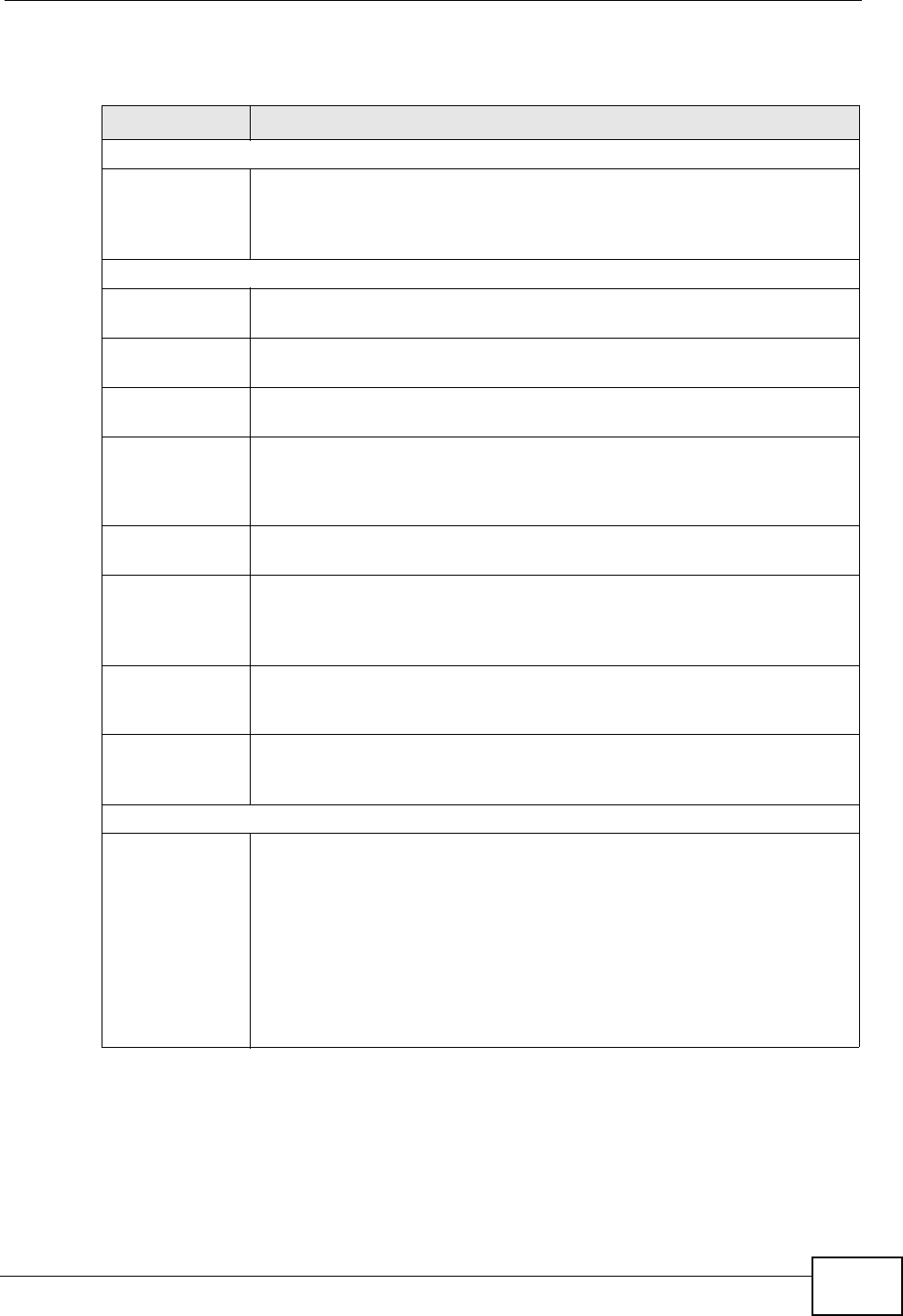
The following table describes the labels in this screen.
Table 56 VoIP > SIP > SIP Service Provider
LABEL DESCRIPTION
SIP Service Provider Selection
Service
Provider
Selection
Select the SIP service provider profile you want to use for the SIP
account you configure in this screen. If you change this field, the screen
automatically refreshes. If you want to configure a new service
provider, select Add New.
General
SIP Service
Provider
Select this if you want the ZyXEL Device to use this SIP provider. Clear
it if you do not want the ZyXEL Device to use this SIP provider.
SIP Service
Provider Name
Enter the name of your SIP service provider.
SIP Local Port Enter the ZyXEL Device’s listening port number, if your VoIP service
provider gave you one. Otherwise, keep the default value.
SIP Server
Address
Enter the IP address or domain name of the SIP server provided by
your VoIP service provider. You can use up to 95 printable ASCII
characters. It does not matter whether the SIP server is a proxy,
redirect or register server.
SIP Server Port Enter the SIP server’s listening port number, if your VoIP service
provider gave you one. Otherwise, keep the default value.
REGISTER
Server Address
Enter the IP address or domain name of the SIP register server, if your
VoIP service provider gave you one. Otherwise, enter the same address
you entered in the SIP Server Address field. You can use up to 95
printable ASCII characters.
REGISTER
Server Port
Enter the SIP register server’s listening port number, if your VoIP
service provider gave you one. Otherwise, enter the same port number
you entered in the SIP Server Port field.
SIP Service
Domain
Enter the SIP service domain name. In the full SIP URI, this is the part
after the @ symbol. You can use up to 127 printable ASCII Extended
set characters.
RTP Port Range
Start Port
End Port
Enter the listening port number(s) for RTP traffic, if your VoIP service
provider gave you this information. Otherwise, keep the default values.
To enter one port number, enter the port number in the Start Port and
End Port fields.
To enter a range of ports,
• enter the port number at the beginning of the range in the Start
Port field.
• enter the port number at the end of the range in the End Port field.
Chapter 16 VoIP
P-2612HNU(L)-FxF User’s Guide
230
DTMF Mode Control how the ZyXEL Device handles the tones that your telephone
makes when you push its buttons. You should use the same mode your
VoIP service provider uses.
RFC2833 - send the DTMF tones in RTP packets.
PCM - send the DTMF tones in the voice data stream. This method
works best when you are using a codec that does not use compression
(like G.711). Codecs that use compression (like G.729 and G.726) can
distort the tones.
SIP INFO - send the DTMF tones in SIP messages.
Transport Type
Transport Type Select the transport layer protocol (TCP, UDP or TCP) used for SIP.
FAX Option This field controls how the ZyXEL Device handles fax messages.
G711 Fax
Passthrough
Select this if the ZyXEL Device should use G.711 to send fax messages.
The peer devices must also use G.711.
T38 Fax Relay Select this if the ZyXEL Device should send fax messages as UDP or
TCP/IP packets through IP networks. This provides better quality, but it
may have inter-operability problems. The peer devices must also use
T.38.
Outbound Proxy
Enable Select this if your VoIP service provider has a SIP outbound server to
handle voice calls. This allows the ZyXEL Device to work with any type
of NAT router and eliminates the need for STUN or a SIP ALG. Turn off
any SIP ALG on a NAT router in front of the ZyXEL Device to keep it
from re-translating the IP address (since this is already handled by the
outbound proxy server).
Server Address Enter the IP address or domain name of the SIP outbound proxy server.
Server Port Enter the SIP outbound proxy server’s listening port, if your VoIP
service provider gave you one. Otherwise, keep the default value.
QoS Tag
SIP TOS Priority
Setting
Enter the DSCP (DiffServ Code Point) number for SIP message
transmissions. The ZyXEL Device creates Class of Service (CoS) priority
tags with this number to SIP traffic that it transmits.
RTP TOS
Priority Setting
Enter the DSCP (DiffServ Code Point) number for RTP voice
transmissions. The ZyXEL Device creates Class of Service (CoS) priority
tags with this number to RTP traffic that it transmits.
Timer Setting
Expiration
Duration
Enter the number of seconds your SIP account is registered with the
SIP register server before it is deleted. The ZyXEL Device automatically
tries to re-register your SIP account when one-half of this time has
passed. (The SIP register server might have a different expiration.)
Register Re-
send timer
Enter the number of seconds the ZyXEL Device waits before it tries
again to register the SIP account, if the first try failed or if there is no
response.
Session Expires Enter the number of seconds the ZyXEL Device lets a SIP session
remain idle (without traffic) before it automatically disconnects the
session.
Table 56 VoIP > SIP > SIP Service Provider (continued)
LABEL DESCRIPTION
Chapter 16 VoIP
P-2612HNU(L)-FxF User’s Guide 231
16.3 The SIP Account Screen
The ZyXEL Device uses a SIP account to make outgoing VoIP calls and check if an
incoming call’s destination number matches your SIP account’s SIP number. In
order to make or receive a VoIP call, you need to enable and configure a SIP
account, and map it to a phone port. The SIP account contains information that
allows your ZyXEL Device to connect to your VoIP service provider.
See Section 16.6 on page 239 for how to map a SIP account to a phone port.
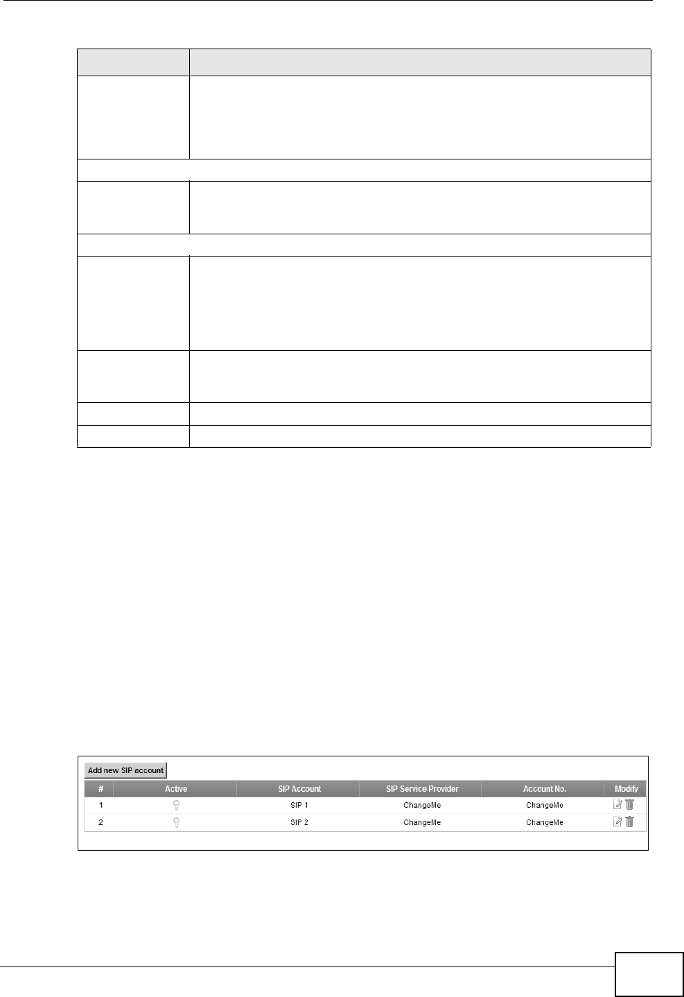
To access the following screen, click VoIP > SIP > SIP Account.
Figure 92 VoIP > SIP > SIP Account
Min-SE Enter the minimum number of seconds the ZyXEL Device lets a SIP
session remain idle (without traffic) before it automatically disconnects
the session. When two SIP devices start a SIP session, they must agree
on an expiration time for idle sessions. This field is the shortest
expiration time that the ZyXEL Device accepts.
Dialing Interval Selection
Dialing Interval
Selection
Enter the number of seconds the ZyXEL Device should wait after you
stop dialing numbers before it makes the phone call. The value depends
on how quickly you dial phone numbers.
Bound Interface Name
Bound Interface
Name
If you select LAN or AnyWAN, the ZyXEL Device automatically
activates the VoIP service when any LAN or WAN connection is up.
If you select MultiWAN, you also need to select the pre-configured
WAN connections. The VoIP service is activated only when the selected
WAN connection is up.
PSTN Fail Over
(“L” models
only)
Select this check box if you want to redirect the outgoing calls to the
PSTN line (that do not use the Internet) when your SIP account is
unregistered or SIP call has failed.
Apply Click Apply to save your changes.
Cancel Click Cancel to restore your previously saved settings.
Table 56 VoIP > SIP > SIP Service Provider (continued)
LABEL DESCRIPTION
Chapter 16 VoIP
P-2612HNU(L)-FxF User’s Guide
232
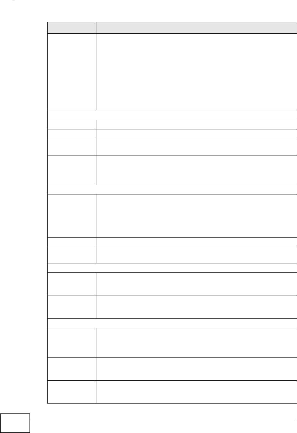
The following table describes the labels in this screen.
Table 57 VoIP > SIP > SIP Account
LABEL DESCRIPTION
Add new SIP
Account
Click this to configure a new SIP account.
# This is the index number of the entry.
Active This shows whether the SIP account is activated or not.
A yellow bulb signifies that this SIP account is activated. A gray bulb
signifies that this SIP account is activated.
SIP Account This shows the name of the SIP account.
Account No. This shows the SIP number.
Modify Click the Edit icon to configure the SIP account.
Click the Delete icon to delete this SIP account from the ZyXEL Device.
Chapter 16 VoIP
P-2612HNU(L)-FxF User’s Guide 233
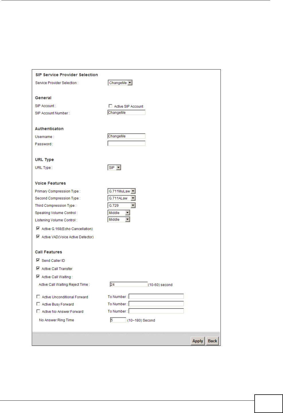
16.3.1 Add/Edit SIP Account
You can configure a new SIP account or edit one. To access this screen, click Add
new SIP Account in the SIP Account screen or the Edit icon next to an existing
account.
Figure 93 SIP Account: Add/Edit
Chapter 16 VoIP
P-2612HNU(L)-FxF User’s Guide
234
Each field is described in the following table.
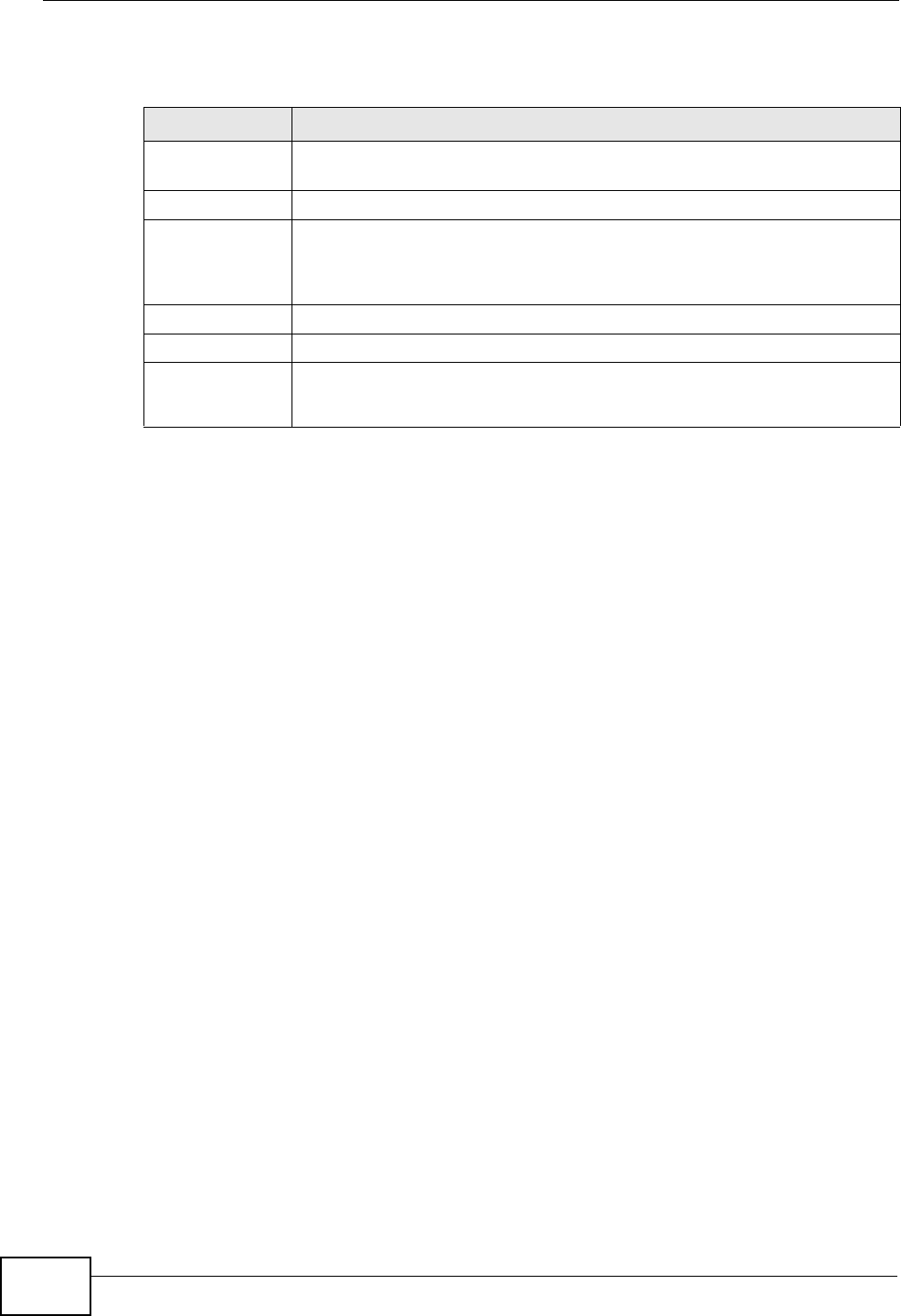
Table 58 SIP Account: Add/Edit
LABEL DESCRIPTION
SIP Service Provider Selection
Service
Provider
Selection
Select the SIP service provider profile you want to use for the SIP
account you configure in this screen.
This field is view-only if you are editing the SIP account.
General
SIP Account Select the Active SIP Account check box if you want the ZyXEL Device
to use this account. Clear it if you do not want the ZyXEL Device to use
this account.
SIP Account
Number
Enter your SIP number. In the full SIP URI, this is the part before the @
symbol. You can use up to 127 printable ASCII characters.
Authentication
Username Enter the user name for registering this SIP account, exactly as it was
given to you. You can use up to 95 printable ASCII characters.
Password Enter the password for registering this SIP account, exactly as it was
given to you. You can use up to 95 printable ASCII characters.
URL Type
URL Type Select whether or not to include the SIP service domain name when the
ZyXEL Device sends the SIP number.
SIP - include the SIP service domain name.
TEL - do not include the SIP service domain name.
Voice Features
Primary
Compression
Type
Secondary
Compression
Type
Third
Compression
Type
Select the type of voice coder/decoder (codec) that you want the ZyXEL
Device to use. G.711 provides higher voice quality but requires more
bandwidth (64 kbps).
•G.711MuLaw is typically used in North America and Japan.
•G.711ALaw is typically used in Europe.
•G.729 only requires 8 kbps.
•G.726-32 operates at 16, 24, 32 or 40 kbps.
•G.722 operates at 48, 56 and 64 kbps.The ZyXEL Device must use
the same codec as the peer. When two SIP devices start a SIP
session, they must agree on a codec.
Select the ZyXEL Device’s first choice for voice coder/decoder.
Select the ZyXEL Device’s second choice for voice coder/decoder. Select
None if you only want the ZyXEL Device to accept the first choice.
Select the ZyXEL Device’s third choice for voice coder/decoder. Select
None if you only want the ZyXEL Device to accept the first or second
choice.
Speaking
Volume
Control
Enter the loudness that the ZyXEL Device uses for speech that it sends
to the peer device.
Minimum is the quietest, and Maximum is the loudest.

Chapter 16 VoIP
P-2612HNU(L)-FxF User’s Guide 235
Listening
Volume
Control
Enter the loudness that the ZyXEL Device uses for speech that it
receives from the peer device.
Minimum is the quietest, and Maximum is the loudest.
Active G.168
(Echo
Cancellation)
Select this if you want to eliminate the echo caused by the sound of
your voice reverberating in the telephone receiver while you talk.
Active VAD
(Voice Active
Detector)
Select this if the ZyXEL Device should stop transmitting when you are
not speaking. This reduces the bandwidth the ZyXEL Device uses.
Call Features
Send Caller ID Select this if you want to send identification when you make VoIP phone
calls. Clear this if you do not want to send identification.
Active Call
Transfer
Select this to enable call transfer on the ZyXEL Device. This allows you
to transfer an incoming call (that you have answered) to another
phone.
Active Call
Waiting
Select this to enable call waiting on the ZyXEL Device. This allows you
to place a call on hold while you answer another incoming call on the
same telephone (directory) number.
Call Waiting
Reject Timer
Specify a time of seconds that the ZyXEL Device waits before rejecting
the second call if you do not answer it.
Active
Unconditional
Forward
Select this if you want the ZyXEL Device to forward all incoming calls to
the specified phone number.
Specify the phone number in the To Number field on the right.
Active Busy
Forward
Select this if you want the ZyXEL Device to forward incoming calls to
the specified phone number if the phone port is busy.
Specify the phone number in the To Number field on the right.
If you have call waiting, the incoming call is forwarded to the specified
phone number if you reject or ignore the second incoming call.
Active No
Answer Forward
Select this if you want the ZyXEL Device to forward incoming calls to
the specified phone number if the call is unanswered. (See No Answer
Time.)
Specify the phone number in the To Number field on the right.
No Answer Ring
Time
This field is used by the Active No Answer Forward feature.
Enter the number of seconds the ZyXEL Device should wait for you to
answer an incoming call before it considers the call is unanswered.
Apply Click Apply to save your changes.
Back Click Back to return to the previous screen without saving.
Table 58 SIP Account: Add/Edit (continued)
LABEL DESCRIPTION
Chapter 16 VoIP
P-2612HNU(L)-FxF User’s Guide
236
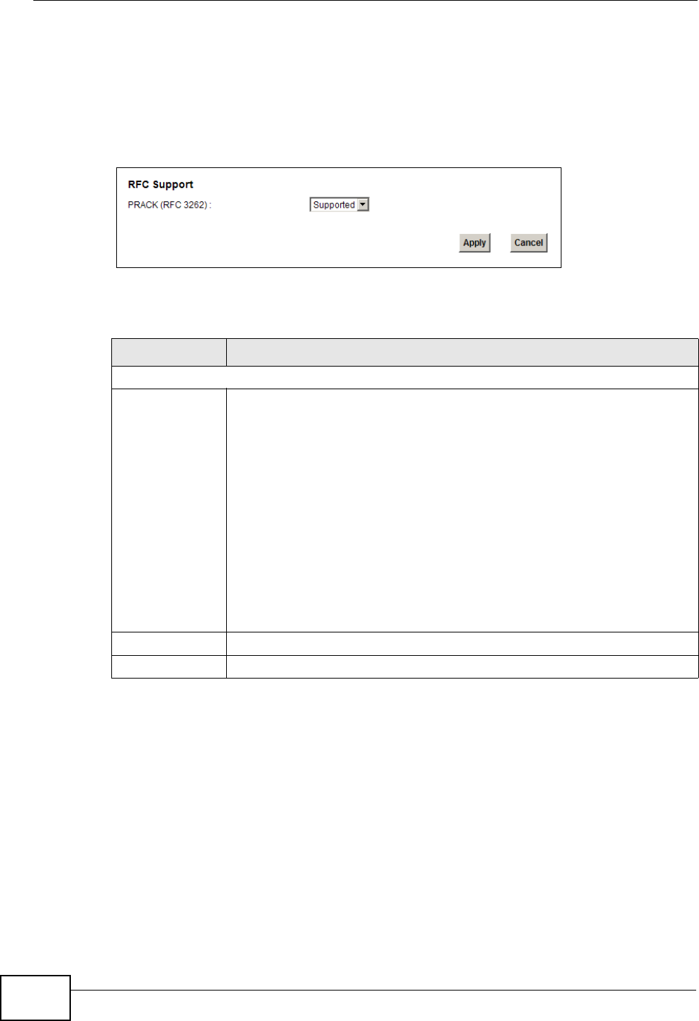
16.4 The SIP Common Screen
Use the Common screen to configure RFC3262 support on the ZyXEL Device. To
access the following screen, click VoIP > SIP > Common.
Figure 94 VoIP > SIP > Common
Each field is described in the following table.
16.5 Multiple SIP Accounts
You can set up two SIP accounts on your ZyXEL Device and your ZyXEL Device is
equipped with two phone ports. By default your ZyXEL Device uses SIP account 1
with both phone ports for outgoing calls, and it uses SIP accounts 1 and 2 for
incoming calls. With this setting, you always use SIP account 1 for your outgoing
calls and you cannot distinguish which SIP account the calls are coming in
through. If you want to control the use of different dialing plans for accounting
purposes or other reasons, you need to configure your phone ports in order to
control which SIP account you are using when placing or receiving calls.
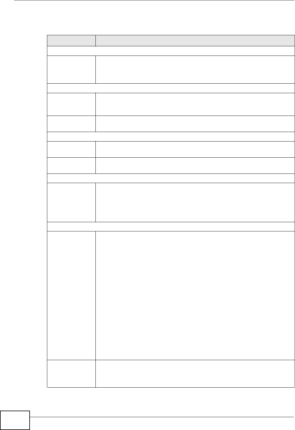
Table 59 VoIP > SIP > Common
LABEL DESCRIPTION
RFC Support
PRACK (RFC
3262)
RFC 3262 defines a mechanism to provide reliable transmission of SIP
provisional response messages, which convey information on the
processing progress of the request. This uses the option tag 100rel and
the Provisional Response ACKnowledgement (PRACK) method.
Select Supported or Required to have the ZyXEL Device include a SIP
Require/Supported header field with the option tag 100rel in all INVITE
requests. When the ZyXEL Device receives a SIP response message
indicating that the phone it called is ringing, the ZyXEL Device sends a
PRACK message to have both sides confirm the message is received.
If you select Supported, the peer device supports the option tag
100rel to send provisional responses reliably.
If you select Required, the peer device requires the option tag 100rel
to send provisional responses reliably.
Apply Click Apply to save your changes.
Cancel Click Cancel to return to the previous screen without saving.
Chapter 16 VoIP
P-2612HNU(L)-FxF User’s Guide 237
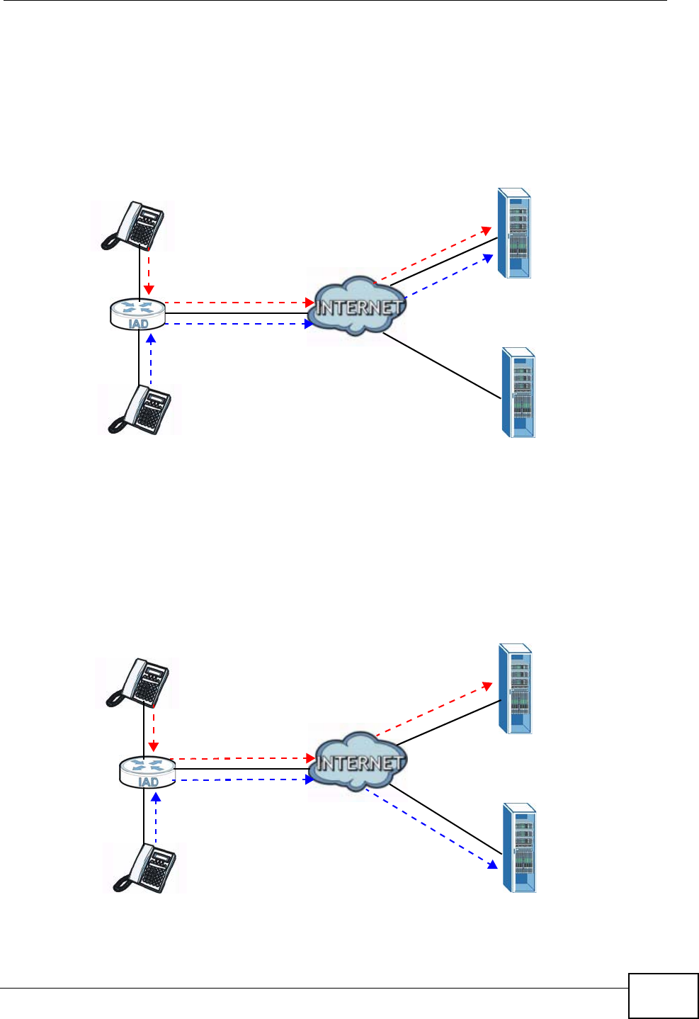
16.5.1 Outgoing Calls
The following figure represents the default behavior of your ZyXEL Device when
two SIP accounts are configured and you are using two phones. When you place a
call from phone port 1 or phone port 2, the ZyXEL Device will use SIP account 1.
Figure 95 Outgoing Calls: Default
In the next example, phone port 1 is configured to use SIP account 1 and phone
port 2 is configured to use SIP account 2. In this case, every time you place a call
through phone port 1, you are using your SIP account 1. Similarly, every time you
place a call through phone port 2, you are using your SIP account 2. To apply
these configuration changes you need to configure the Phone Device screen. See
Section 16.6 on page 239.
Figure 96 Outgoing Calls: Individual Configuration
PHONE 1
SIP 1
SIP 2
PHONE 2
SIP 1
SIP 2
PHONE 1
PHONE 2
Chapter 16 VoIP
P-2612HNU(L)-FxF User’s Guide
238
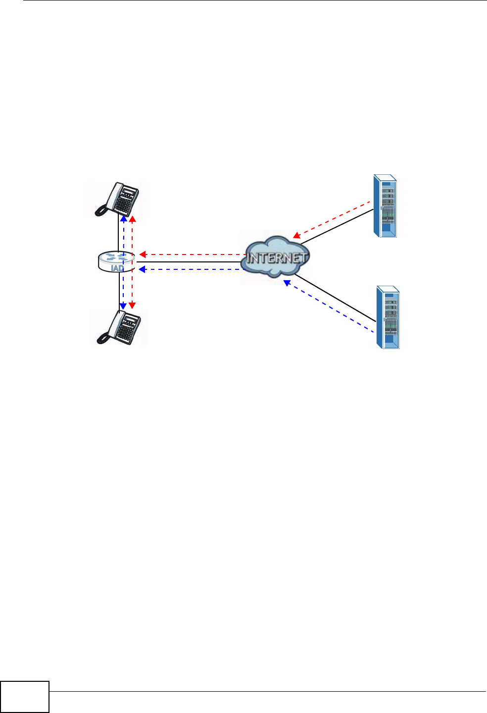
16.5.2 Incoming Calls
The following example shows the default behavior of your ZyXEL Device for
incoming calls when two SIP accounts are configured and you are using two
phones. When a call comes in from your SIP account 1, the phones connected to
both phone port 1 and phone port 2 ring. Similarly, when a call comes in from your
SIP account 2, the phones connected to both phone port 1 and phone port 2 ring.
In either case you are not sure which SIP account the call is coming from.
Figure 97 Incoming Calls: Default
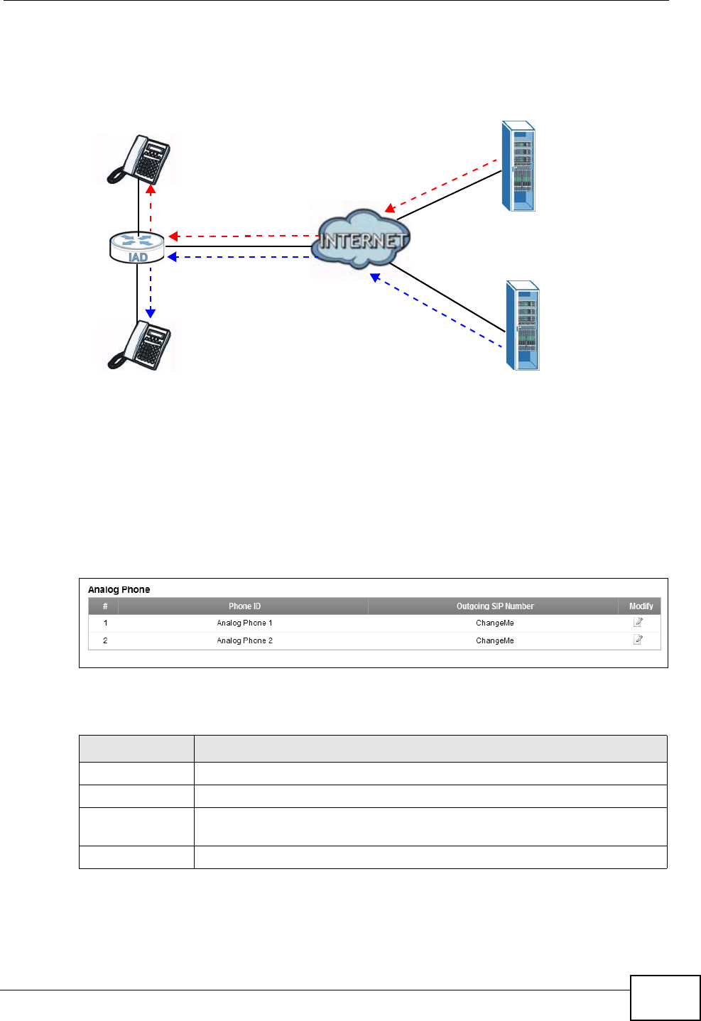
In the next example, phone port 1 is configured to use SIP account 1 and phone
port 2 is configured to use SIP account 2 for incoming calls. In this case, every
time you receive a call from your SIP account 1, the phone connected to phone
port 1 rings. Similarly, every time you receive a call from your SIP account 2,
SIP 1
SIP 2
PHONE 1
PHONE 2
Chapter 16 VoIP
P-2612HNU(L)-FxF User’s Guide 239
phone port 2 rings. To apply these configuration changes you need to configure
the Phone Device screen. See Section 16.6 on page 239.
Figure 98 Incoming Calls: Individual Configuration
16.6 The Phone Device Screen
Use this screen to control which SIP accounts and PSTN line each phone uses.
Click VoIP > Phone to access the Phone Device screen.
Figure 99 VoIP > Phone > Phone Device
The following table describes the labels in this screen.
SIP 1
SIP 2
PHONE 1
PHONE 2
Table 60 VoIP > Phone > Phone Device
LABEL DESCRIPTION
# This is the index number of the entry.
Phone ID This is the phone device number.
Outgoing SIP
Number
This is the outgoing SIP number of the phone device.
Modify Click the Edit icon to configure the SIP account.
Chapter 16 VoIP
P-2612HNU(L)-FxF User’s Guide
240
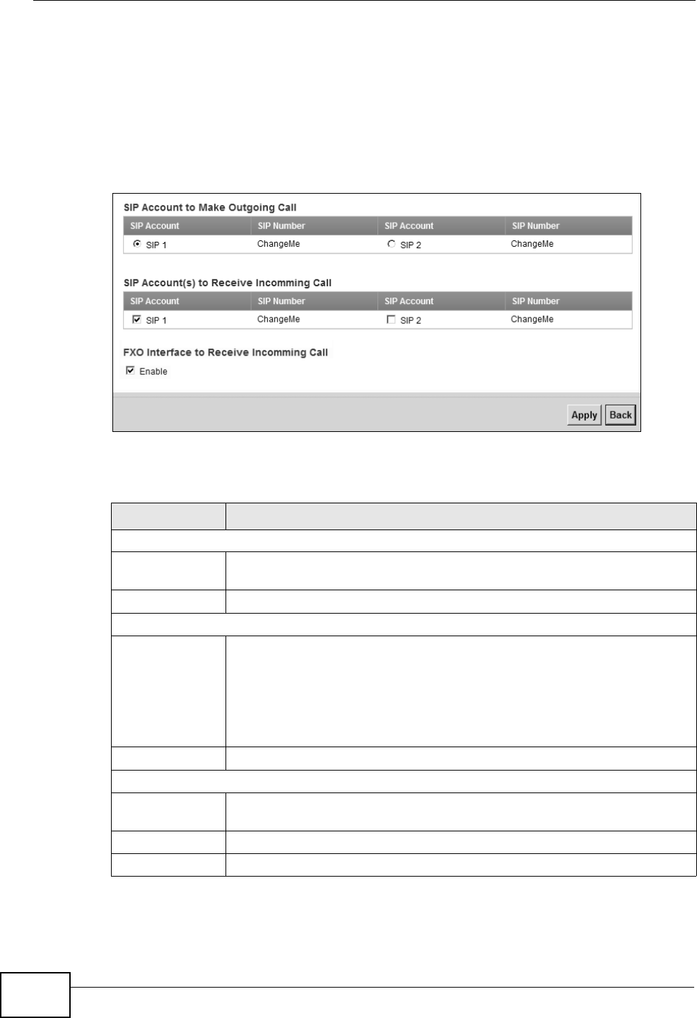
16.6.1 Edit Phone Device
You can edit an SIP account by clicking the Edit icon next to an SIP account entry.
You cannot edit the account if it is not activated. Go to VoIP > SIP > SIP
Account > Edit to activate an SIP account (see Section 16.3.1 on page 233 for
more information).
Figure 100 Phone Device: Edit
The following table describes the labels in this screen.
Table 61 Phone Device: Edit
LABEL DESCRIPTION
SIP Account to Make Outgoing Call
SIP Account Select the SIP account you want to use when making outgoing calls
with the analog phone connected to this phone port.
SIP Number This shows the SIP account number.
SIP Account(s) to Receive Incoming Call
SIP Account Select a SIP account if you want to receive phone calls for the selected
SIP account on this phone port.
If you select more than one SIP account for incoming calls, there is no
way to distinguish between them when you receive phone calls. If you
do not select a source for incoming calls, you cannot receive any calls
on this phone port.
SIP Number This shows the SIP account number.
FXO Interface to Receive Incoming Call
Enable Select this if you want to receive phone calls from the PSTN line (that
do not use the Internet) on this phone port.
Apply Click Apply to save your changes.
Back Click Back to return to the previous screen without saving.
Chapter 16 VoIP
P-2612HNU(L)-FxF User’s Guide 241
16.7 The Region Screen
Use this screen to maintain settings that depend on which region of the world the
ZyXEL Device is in. To access this screen, click VoIP > Phone > Region.
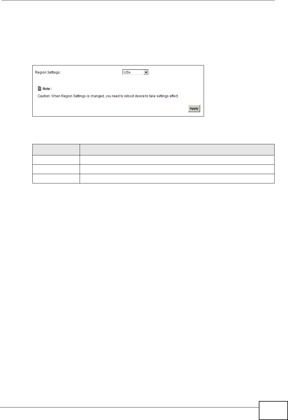
Figure 101 VoIP > Phone > Region
Each field is described in the following table.
16.8 The Call Rule Screen
Use this screen to add, edit, or remove speed-dial numbers for outgoing calls.
Speed dial provides shortcuts for dialing frequently-used (VoIP) phone numbers.
You also have to create speed-dial entries if you want to call SIP numbers that
contain letters. Once you have configured a speed dial rule, you can use a shortcut
(the speed dial number, #01 for example) on your phone's keypad to call the
phone number.
Table 62 VoIP > Phone > Region
LABEL DESCRIPTION
Region Settings Select the place in which the ZyXEL Device is located.
Apply Click Apply to save your changes.
Cancel Click Cancel to restore your previously saved settings.
Chapter 16 VoIP
P-2612HNU(L)-FxF User’s Guide
242
To access this screen, click VoIP > Phone > Call Rule.
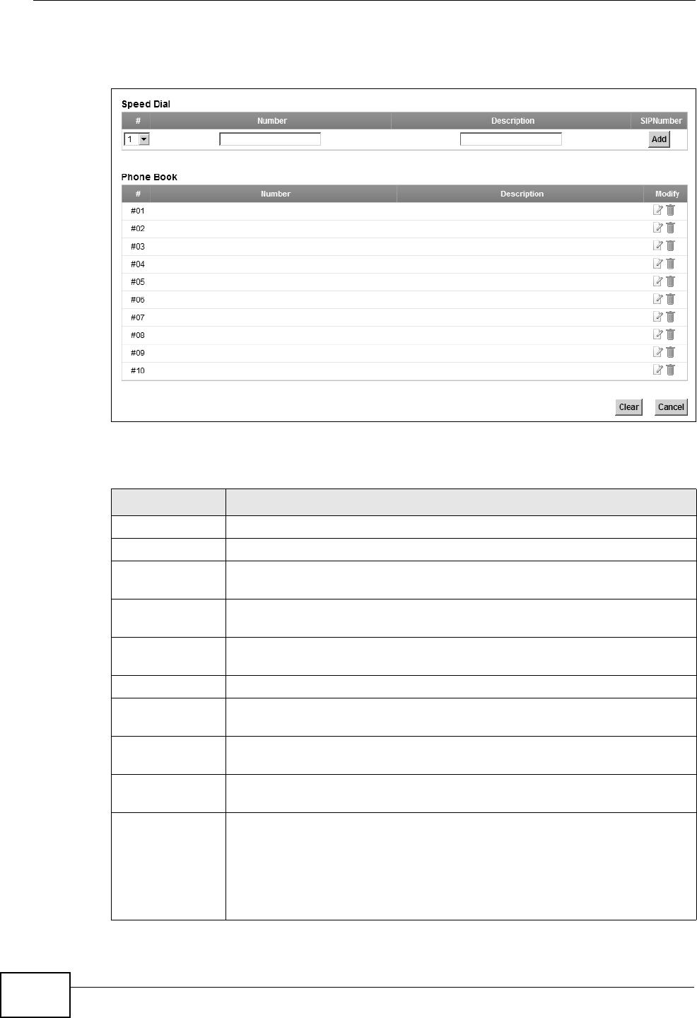
Figure 102 VoIP > Phone > Call Rule
Each field is described in the following table.
Table 63 VoIP > Phone > Call Rule
LABEL DESCRIPTION
Speed Dial Use this section to create or edit speed-dial entries.
#Select the speed-dial number you want to use for this phone number.
Number Enter the SIP number you want the ZyXEL Device to call when you dial
the speed-dial number.
Description Enter a short description to identify the party you call when you dial the
speed-dial number. You can use up to 127 printable ASCII characters.
Add Click this to use the information in the Speed Dial section to update
the Speed Dial Phone Book section.
Phone Book Use this section to look at all the speed-dial entries and to erase them.
# This field displays the speed-dial number you should dial to use this
entry.
Number This field displays the SIP number the ZyXEL Device calls when you dial
the speed-dial number.
Description This field displays a short description of the party you call when you dial
the speed-dial number.
Modify Use this field to edit or erase the speed-dial entry.
Click the Edit icon to copy the information for this speed-dial entry into
the Speed Dial section, where you can change it. Click Add when you
finish editing to change the configurations.
Click the Delete icon to erase this speed-dial entry.
Chapter 16 VoIP
P-2612HNU(L)-FxF User’s Guide 243
16.9 The FXO Screen (“L” Models Only)
With PSTN line you can make and receive regular PSTN phone calls. Use a prefix
number to make a regular call. When the device does not have power, you can
make regular calls without dialing a prefix number.
When the ZyXEL Device does not have power, only the phone
connected to the PHONE port1 can be used for making calls.
Ensure you know which phone this is, so that in case of
emergency you can make outgoing calls.
Use the FXO screen to set up the PSTN line you use to make regular phone calls
which do not use the Internet. To access this screen, click VoIP > FXO.
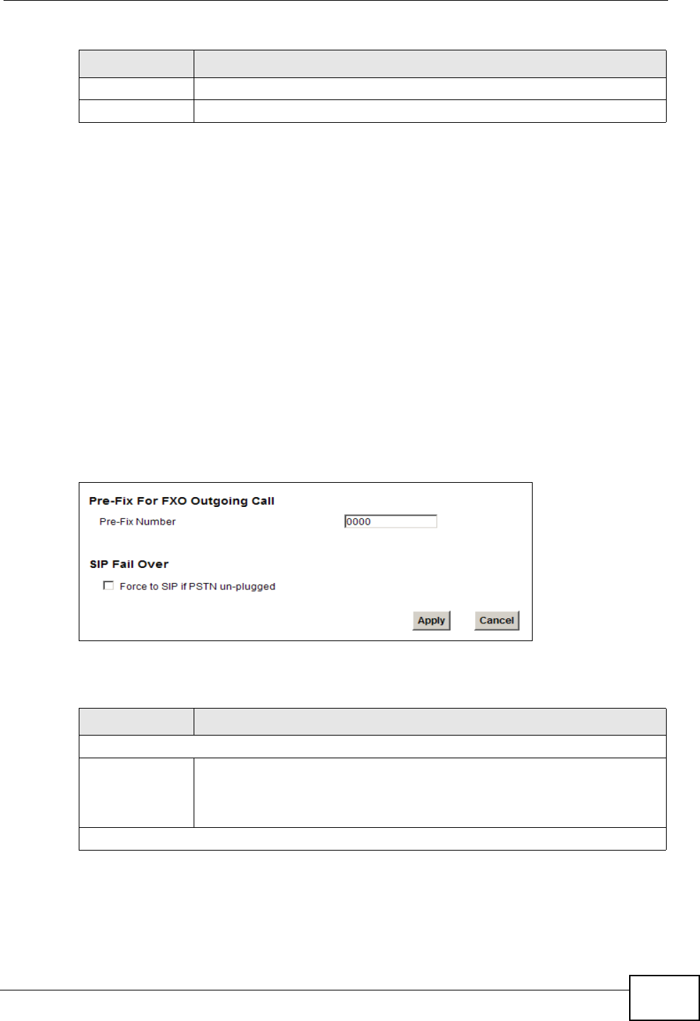
Figure 103 VoIP > FXO
Each field is described in the following table.
Clear Click this to erase all the speed-dial entries.
Cancel Click this to set every field in this screen to its last-saved value.
Table 63 VoIP > Phone > Call Rule (continued)
LABEL DESCRIPTION
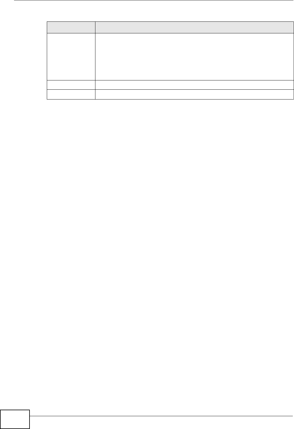
Table 64 VoIP > FXO
LABEL DESCRIPTION
Pre-Fix For FXO Outgoing Call
Pre-Fix Number Enter 1 - 7 numbers you dial before you dial the phone number, if you
want to make a regular phone call while one of your SIP accounts is
registered. These numbers tell the ZyXEL Device that you want to make
a regular phone call.
SIP Fail Over
Chapter 16 VoIP
P-2612HNU(L)-FxF User’s Guide
244
16.10 Technical Reference
This section contains background material relevant to the VoIP screens.
16.10.1 VoIP
VoIP is the sending of voice signals over Internet Protocol. This allows you to
make phone calls and send faxes over the Internet at a fraction of the cost of
using the traditional circuit-switched telephone network. You can also use servers
to run telephone service applications like PBX services and voice mail. Internet
Telephony Service Provider (ITSP) companies provide VoIP service.
Circuit-switched telephone networks require 64 kilobits per second (Kbps) in each
direction to handle a telephone call. VoIP can use advanced voice coding
techniques with compression to reduce the required bandwidth.
16.10.2 SIP
The Session Initiation Protocol (SIP) is an application-layer control (signaling)
protocol that handles the setting up, altering and tearing down of voice and
multimedia sessions over the Internet.
SIP signaling is separate from the media for which it handles sessions. The media
that is exchanged during the session can use a different path from that of the
signaling. SIP handles telephone calls and can interface with traditional circuit-
switched telephone networks.
SIP Identities
A SIP account uses an identity (sometimes referred to as a SIP address). A
complete SIP identity is called a SIP URI (Uniform Resource Identifier). A SIP
account's URI identifies the SIP account in a way similar to the way an e-mail
Force to SIP if
PSTN un-
plugged
Select this check box to have the ZyXEL Device redirect outgoing calls
to the registered SIP account if the ZyXEL Device is not connected to
the PSTN network.
When you try to make a PSTN call, but the PSTN port on the ZyXEL
Device is unplugged, the ZyXEL Device uses the phone port’s registered
SIP account to make the call.
Apply Click Apply to save your changes.
Cancel Click Cancel to restore your previously saved settings.
Table 64 VoIP > FXO (continued)
LABEL DESCRIPTION

Chapter 16 VoIP
P-2612HNU(L)-FxF User’s Guide 245
address identifies an e-mail account. The format of a SIP identity is SIP-
Number@SIP-Service-Domain.
SIP Number
The SIP number is the part of the SIP URI that comes before the “@” symbol. A
SIP number can use letters like in an e-mail address (johndoe@your-ITSP.com for
example) or numbers like a telephone number (1122334455@VoIP-provider.com
for example).
SIP Service Domain
The SIP service domain of the VoIP service provider is the domain name in a SIP
URI. For example, if the SIP address is 1122334455@VoIP-provider.com, then
“VoIP-provider.com” is the SIP service domain.
SIP Registration
Each ZyXEL Device is an individual SIP User Agent (UA). To provide voice service,
it has a public IP address for SIP and RTP protocols to communicate with other
servers.
A SIP user agent has to register with the SIP registrar and must provide
information about the users it represents, as well as its current IP address (for the
routing of incoming SIP requests). After successful registration, the SIP server
knows that the users (identified by their dedicated SIP URIs) are represented by
the UA, and knows the IP address to which the SIP requests and responses should
be sent.
Registration is initiated by the User Agent Client (UAC) running in the VoIP
gateway (the ZyXEL Device). The gateway must be configured with information
letting it know where to send the REGISTER message, as well as the relevant user
and authorization data.
A SIP registration has a limited lifespan. The User Agent Client must renew its
registration within this lifespan. If it does not do so, the registration data will be
deleted from the SIP registrar's database and the connection broken.
The ZyXEL Device attempts to register all enabled subscriber ports when it is
switched on. When you enable a subscriber port that was previously disabled, the
ZyXEL Device attempts to register the port immediately.
Authorization Requirements
SIP registrations (and subsequent SIP requests) require a username and
password for authorization. These credentials are validated via a challenge /
Chapter 16 VoIP
P-2612HNU(L)-FxF User’s Guide
246
response system using the HTTP digest mechanism (as detailed in RFC3261, "SIP:
Session Initiation Protocol").
SIP Servers
SIP is a client-server protocol. A SIP client is an application program or device that
sends SIP requests. A SIP server responds to the SIP requests.
When you use SIP to make a VoIP call, it originates at a client and terminates at a
server. A SIP client could be a computer or a SIP phone. One device can act as
both a SIP client and a SIP server.
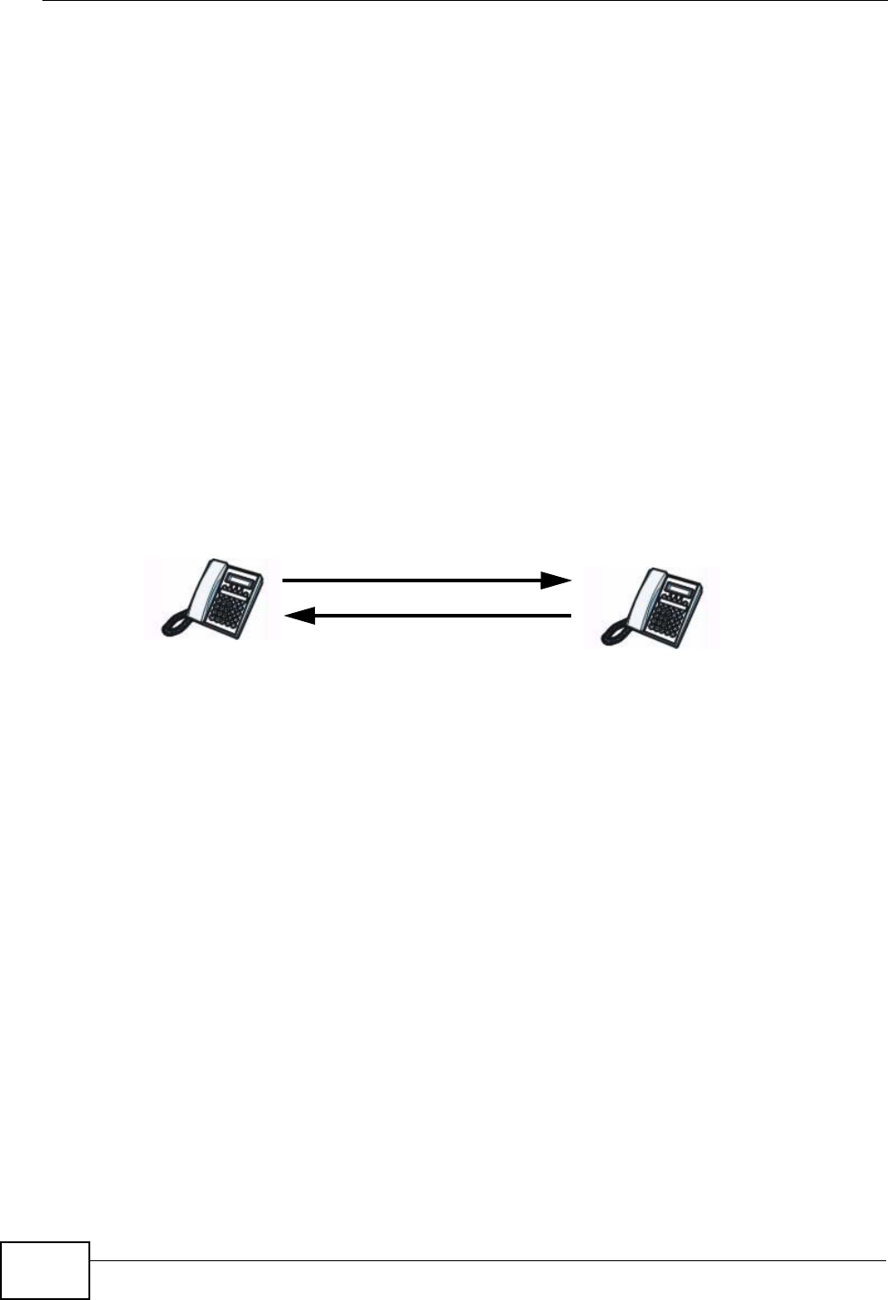
SIP User Agent
A SIP user agent can make and receive VoIP telephone calls. This means that SIP
can be used for peer-to-peer communications even though it is a client-server
protocol. In the following figure, either A or B can act as a SIP user agent client to
initiate a call. A and B can also both act as a SIP user agent to receive the call.
Figure 104 SIP User Agent
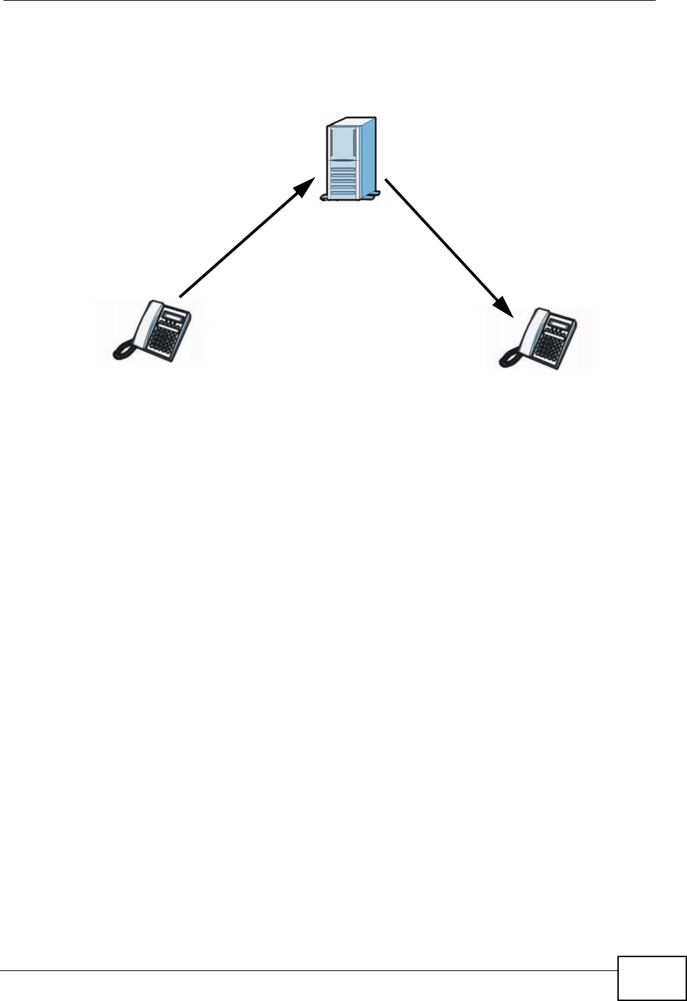
SIP Proxy Server
A SIP proxy server receives requests from clients and forwards them to another
server.
In the following example, you want to use client device Ato call someone who is
using client device C.
1The client device (A in the figure) sends a call invitation to the SIP proxy server B.
AB
Chapter 16 VoIP
P-2612HNU(L)-FxF User’s Guide 247
2The SIP proxy server forwards the call invitation to C.
Figure 105 SIP Proxy Server
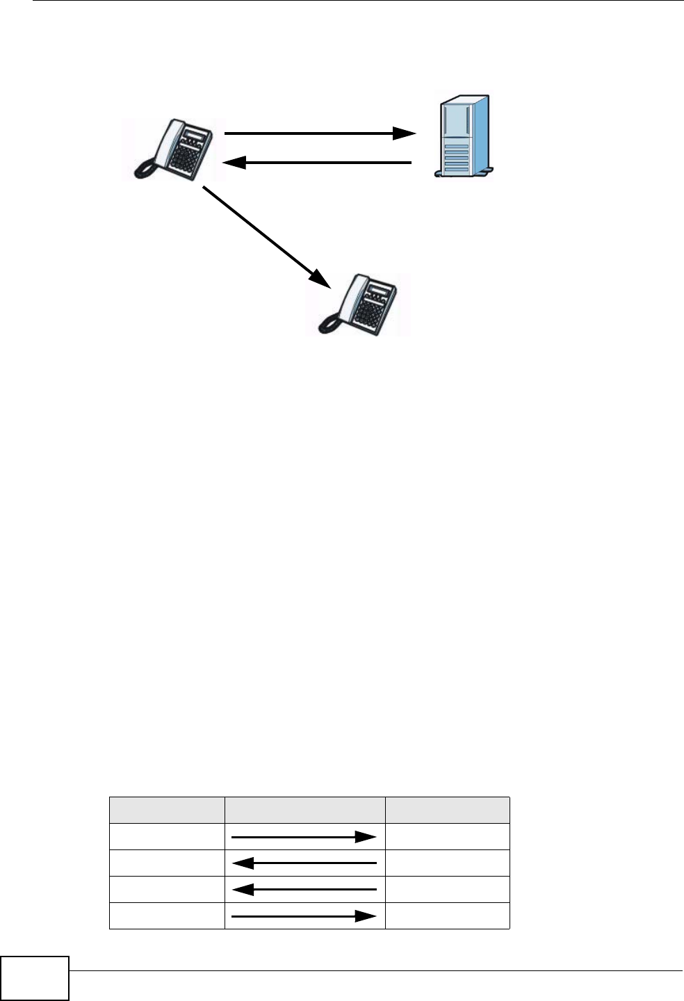
SIP Redirect Server
A SIP redirect server accepts SIP requests, translates the destination address to
an IP address and sends the translated IP address back to the device that sent the
request. Then the client device that originally sent the request can send requests
to the IP address that it received back from the redirect server. Redirect servers
do not initiate SIP requests.
In the following example, you want to use client device Ato call someone who is
using client device C.
1Client device Asends a call invitation for Cto the SIP redirect server B.
2The SIP redirect server sends the invitation back to A with C’s IP address (or
domain name).
B
AC
12
Chapter 16 VoIP
P-2612HNU(L)-FxF User’s Guide
248
3Client device Athen sends the call invitation to client device C.
Figure 106 SIP Redirect Server
SIP Register Server
A SIP register server maintains a database of SIP identity-to-IP address (or
domain name) mapping. The register server checks your user name and password
when you register.
RTP
When you make a VoIP call using SIP, the RTP (Real time Transport Protocol) is
used to handle voice data transfer. See RFC 3550 for details on RTP.
Pulse Code Modulation
Pulse Code Modulation (PCM) measures analog signal amplitudes at regular time
intervals and converts them into bits.
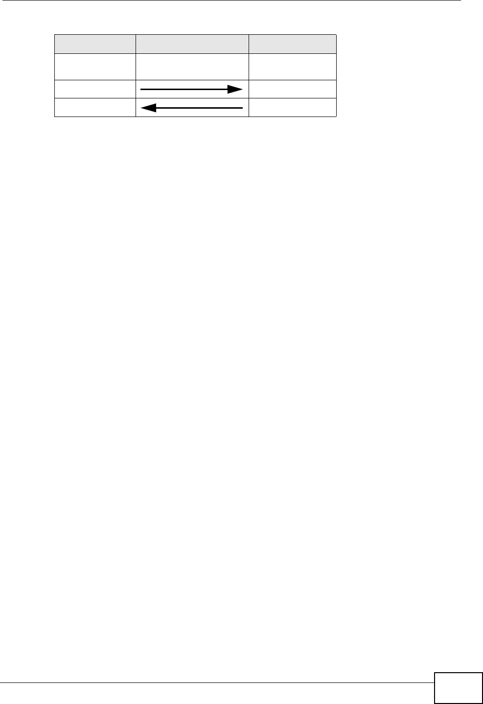
SIP Call Progression
The following figure displays the basic steps in the setup and tear down of a SIP
call. A calls B.
Table 65 SIP Call Progression
A B
1. INVITE
2. Ringing
3. OK
4. ACK
1
2
3
AB
C
Chapter 16 VoIP
P-2612HNU(L)-FxF User’s Guide 249
1Asends a SIP INVITE request to B. This message is an invitation for B to
participate in a SIP telephone call.
2Bsends a response indicating that the telephone is ringing.
3Bsends an OK response after the call is answered.
4A then sends an ACK message to acknowledge that B has answered the call.
5Now A and B exchange voice media (talk).
6After talking, A hangs up and sends a BYE request.
7B replies with an OK response confirming receipt of the BYE request and the call is
terminated.
Voice Coding
A codec (coder/decoder) codes analog voice signals into digital signals and
decodes the digital signals back into analog voice signals. The ZyXEL Device
supports the following codecs.
• G.711 is a Pulse Code Modulation (PCM) waveform codec. PCM measures analog
signal amplitudes at regular time intervals and converts them into digital
samples. G.711 provides very good sound quality but requires 64 kbps of
bandwidth.
• G.726 is an Adaptive Differential PCM (ADPCM) waveform codec that uses a
lower bitrate than standard PCM conversion. ADPCM converts analog audio into
digital signals based on the difference between each audio sample and a
prediction based on previous samples. The more similar the audio sample is to
the prediction, the less space needed to describe it. G.726 operates at 16, 24,
32 or 40 kbps.
• G.729 is an Analysis-by-Synthesis (AbS) hybrid waveform codec that uses a
filter based on information about how the human vocal tract produces sounds.
G.729 provides good sound quality and reduces the required bandwidth to 8
kbps.
5.Dialogue (voice
traffic)
6. BYE
7. OK
Table 65 SIP Call Progression (continued)
A B

Chapter 16 VoIP
P-2612HNU(L)-FxF User’s Guide
250
PSTN Call Setup Signaling
Dual-Tone MultiFrequency (DTMF) signaling uses pairs of frequencies (one lower
frequency and one higher frequency) to set up calls. It is also known as Touch
Tone®. Each of the keys on a DTMF telephone corresponds to a different pair of
frequencies.
Pulse dialing sends a series of clicks to the local phone office in order to dial
numbers.3
MWI (Message Waiting Indication)
Enable Message Waiting Indication (MWI) enables your phone to give you a
message–waiting (beeping) dial tone when you have a voice message(s). Your
VoIP service provider must have a messaging system that sends message waiting
status SIP packets as defined in RFC 3842.
16.10.3 Quality of Service (QoS)
Quality of Service (QoS) refers to both a network's ability to deliver data with
minimum delay, and the networking methods used to provide bandwidth for real-
time multimedia applications.
Type of Service (ToS)
Network traffic can be classified by setting the ToS (Type of Service) values at the
data source (for example, at the ZyXEL Device) so a server can decide the best
method of delivery, that is the least cost, fastest route and so on.
DiffServ
DiffServ is a class of service (CoS) model that marks packets so that they receive
specific per-hop treatment at DiffServ-compliant network devices along the route
based on the application types and traffic flow. Packets are marked with DiffServ
Code Points (DSCP) indicating the level of service desired. This allows the
intermediary DiffServ-compliant network devices to handle the packets differently
depending on the code points without the need to negotiate paths or remember
state information for every flow. In addition, applications do not have to request a
particular service or give advanced notice of where the traffic is going.4
3. The ZyXEL Device does not support pulse dialing at the time of writing.
4. The ZyXEL Device does not support DiffServ at the time of writing.

Chapter 16 VoIP
P-2612HNU(L)-FxF User’s Guide 251
DSCP and Per-Hop Behavior
DiffServ defines a new DS (Differentiated Services) field to replace the Type of
Service (TOS) field in the IP header. The DS field contains a 2-bit unused field and
a 6-bit DSCP field which can define up to 64 service levels. The following figure
illustrates the DS field.
DSCP is backward compatible with the three precedence bits in the ToS octet so
that non-DiffServ compliant, ToS-enabled network device will not conflict with the
DSCP mapping.
Figure 107 DiffServ: Differentiated Service Field
The DSCP value determines the forwarding behavior, the PHB (Per-Hop Behavior),
that each packet gets across the DiffServ network. Based on the marking rule,
different kinds of traffic can be marked for different priorities of forwarding.
Resources can then be allocated according to the DSCP values and the configured
policies.
VLAN Tagging
Virtual Local Area Network (VLAN) allows a physical network to be partitioned into
multiple logical networks. Only stations within the same group can communicate
with each other.
Your ZyXEL Device can add IEEE 802.1Q VLAN ID tags to voice frames that it
sends to the network. This allows the ZyXEL Device to communicate with a SIP
server that is a member of the same VLAN group. Some ISPs use the VLAN tag to
identify voice traffic and give it priority over other traffic.
16.10.4 Phone Services Overview
Supplementary services such as call hold, call waiting, and call transfer. are
generally available from your VoIP service provider. The ZyXEL Device supports
the following services:
• Call Hold
• Call Waiting
• Making a Second Call
• Call Transfer
• Three-Way Conference
DSCP
(6-bit)
Unused
(2-bit)
Chapter 16 VoIP
P-2612HNU(L)-FxF User’s Guide
252
• Internal Calls
• Do not Disturb
Note: To take full advantage of the supplementary phone services available through
the ZyXEL Device's phone ports, you may need to subscribe to the services
from your VoIP service provider.
The Flash Key
Flashing means to press the hook for a short period of time (a few hundred
milliseconds) before releasing it. On newer telephones, there should be a "flash"
key (button) that generates the signal electronically. If the flash key is not
available, you can tap (press and immediately release) the hook by hand to
achieve the same effect. However, using the flash key is preferred since the timing
is much more precise. With manual tapping, if the duration is too long, it may be
interpreted as hanging up by the ZyXEL Device.
You can invoke all the supplementary services by using the flash key.
Europe Type Supplementary Phone Services
This section describes how to use supplementary phone services with the Europe
Type Call Service Mode. Commands for supplementary services are listed in the
table below.
After pressing the flash key, if you do not issue the sub-command before the
default sub-command time-out (2 seconds) expires or issue an invalid sub-
command, the current operation will be aborted.
Table 66 European Flash Key Commands
COMMAND SUB-
COMMAND DESCRIPTION
Flash Put a current call on hold to place a second call.
Switch back to the call (if there is no second call).
Flash 0 Drop the call presently on hold or reject an incoming call
which is waiting for answer.
Flash 1 Disconnect the current phone connection and answer the
incoming call or resume with caller presently on hold.
Flash 2 1. Switch back and forth between two calls.
2. Put a current call on hold to answer an incoming call.
3. Separate the current three-way conference call into
two individual calls (one is on-line, the other is on hold).
Flash 3 Create three-way conference connection.
Flash *98# Transfer the call to another phone.

Chapter 16 VoIP
P-2612HNU(L)-FxF User’s Guide 253
European Call Hold
Call hold allows you to put a call (A) on hold by pressing the flash key.
If you have another call, press the flash key and then “2” to switch back and forth
between caller A and Bby putting either one on hold.
Press the flash key and then “0” to disconnect the call presently on hold and keep
the current call on line.
Press the flash key and then “1” to disconnect the current call and resume the call
on hold.
If you hang up the phone but a caller is still on hold, there will be a remind ring.
European Call Waiting
This allows you to place a call on hold while you answer another incoming call on
the same telephone (directory) number.
If there is a second call to a telephone number, you will hear a call waiting tone.
Take one of the following actions.
• Reject the second call.
Press the flash key and then press “0”.
• Disconnect the first call and answer the second call.
Either press the flash key and press “1”, or just hang up the phone and then
answer the phone after it rings.
• Put the first call on hold and answer the second call.
Press the flash key and then “2”.
European Call Transfer
Do the following to transfer a call (that you have answered) to another phone
number.
1Press the flash key to put the caller on hold.
2When you hear the dial tone, dial “*98#” followed by the number to which you
want to transfer the call. to operate the Intercom.
3After you hear the ring signal or the second party answers it, hang up the phone.
European Three-Way Conference
Use the following steps to make three-way conference calls.

Chapter 16 VoIP
P-2612HNU(L)-FxF User’s Guide
254
1When you are on the phone talking to someone, press the flash key to put the call
on hold and get a dial tone.
2Dial a phone number directly to make another call.
3When the second call is answered, press the flash key and press “3” to create a
three-way conversation.
4Hang up the phone to drop the connection.
5If you want to separate the activated three-way conference into two individual
connections (one is on-line, the other is on hold), press the flash key and press
“2”.
P-2612HNU(L)-FxF User’s Guide 255
CHAPTER 17
Logs
17.1 Overview
The web configurator allows you to choose which categories of events and/or
alerts to have the ZyXEL Device log and then display the logs or have the ZyXEL
Device send them to an administrator (as e-mail) or to a syslog server.
Note: The ZyXEL Device’s log feature is only for Voice over IP (VoIP).
17.1.1 What You Can Do in this Chapter
• Use the Phone Log screen to view phone logs and alert messages (Section 17.2
on page 255).
• Use The VoIP Call History screen to view the details of the calls performed on
the ZyXEL Device (Section 17.3 on page 256).
17.2 The Phone Log Screen
Click System Monitor > Log to open the Phone Log screen. Use this screen to
view phone logs and alert messages. You can select the type of log and level of
severity to display.
Figure 108 System Monitor > Log > Phone Log
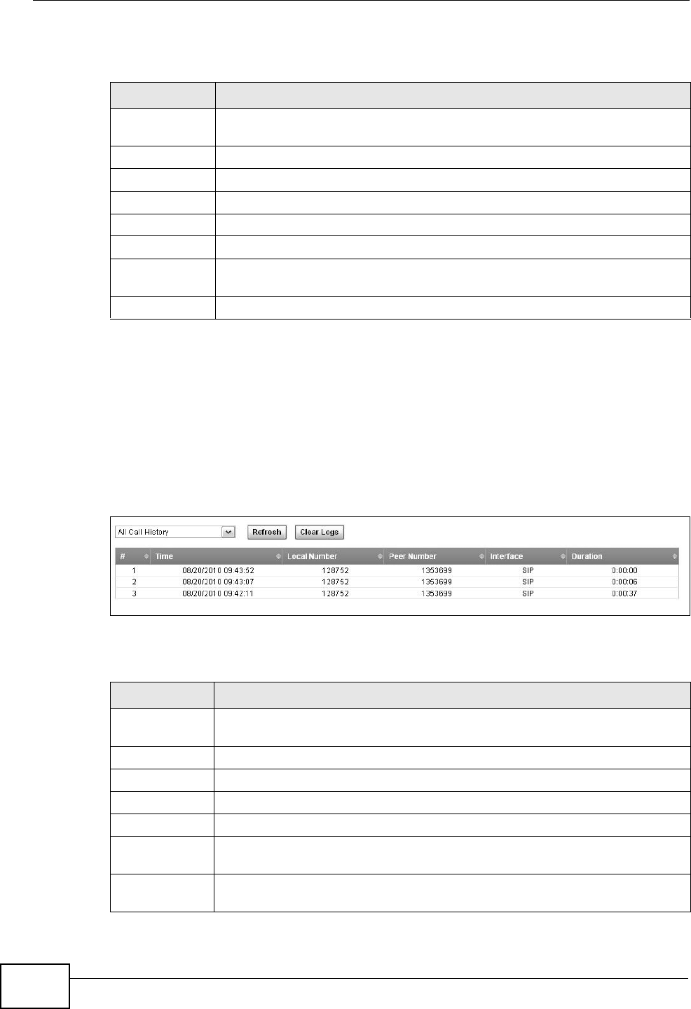
Chapter 17 Logs
P-2612HNU(L)-FxF User’s Guide
256
The following table describes the fields in this screen.
17.3 The VoIP Call History Screen
Click System Monitor > Log > Call History to open the VoIP Call History
screen. Use this screen to see the details of the calls performed on the ZyXEL
Device.
Figure 109 System Monitor > Log > Call History
The following table describes the fields in this screen.
Table 67 System Monitor > Log > Phone Log
LABEL DESCRIPTION
Select a category of logs to view from the drop-down list box. select All
Logs to view all logs.
Level Select the severity level that you want to view.
Refresh Click this to renew the log screen.
Clear Logs Click this to delete all the logs.
# This field is a sequential value and is not associated with a specific entry.
Time This field displays the time the log was recorded.
Level This field displays the severity level of the logs that the device is to send
to this syslog server.
Message This field states the reason for the log.
Table 68 System Monitor > Log > Call History
LABEL DESCRIPTION
Select a category of call records to view from the drop-down list box.
select All Call History to view all call records.
Refresh Click this to renew the log screen.
Clear Logs Click this to delete all the logs.
# This field is a sequential value and is not associated with a specific entry.
Time This field displays the time the call was recorded.
Local Number This field displays the phone number you used to make or receive this
call.
Peer Number This field displays the phone number you called or from which this call is
made.
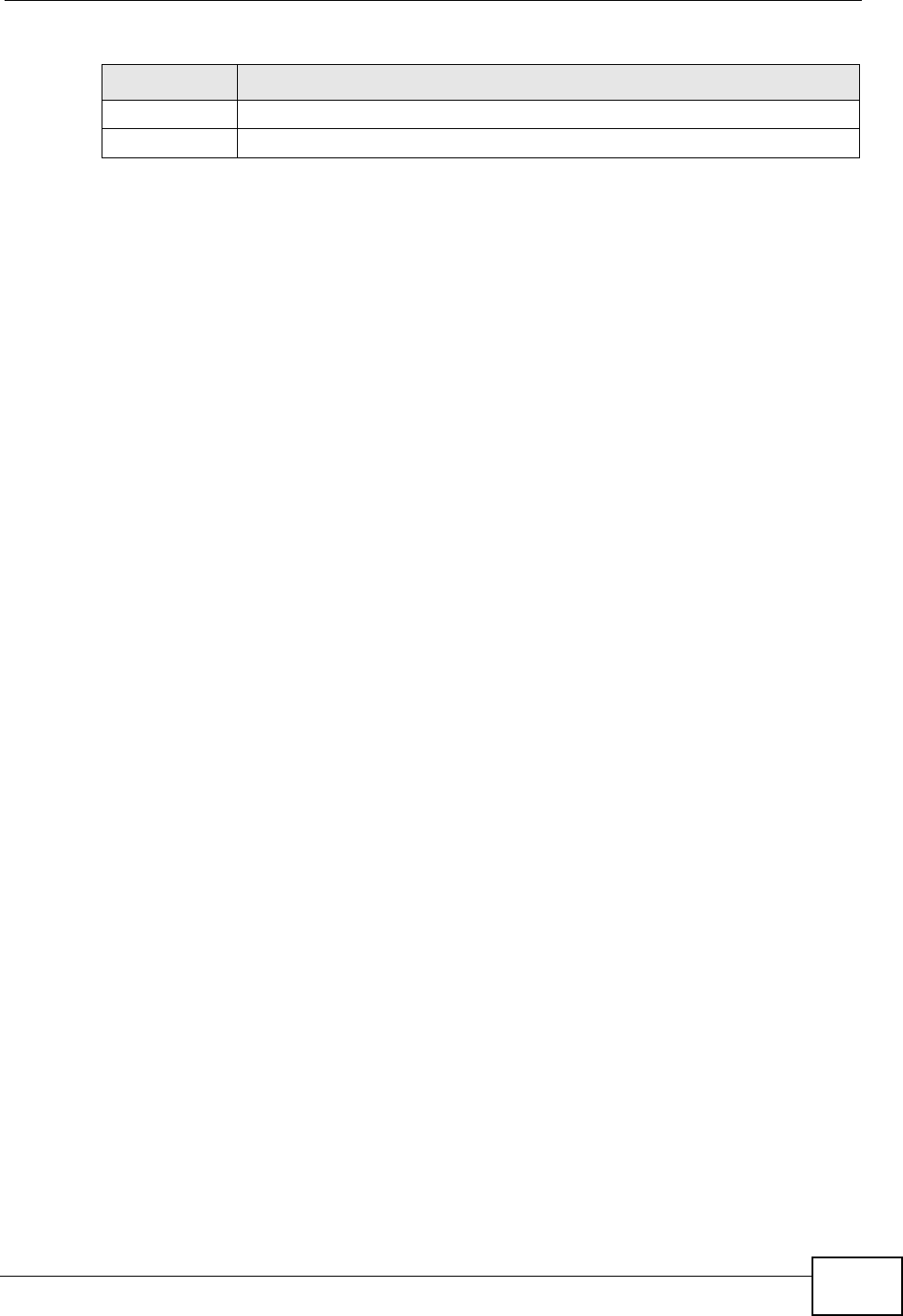
Chapter 17 Logs
P-2612HNU(L)-FxF User’s Guide 257
Interface This field displays the type of the call.
Duration This field displays how long the call lasted.
Table 68 System Monitor > Log > Call History
LABEL DESCRIPTION

Chapter 17 Logs
P-2612HNU(L)-FxF User’s Guide
258

P-2612HNU(L)-FxF User’s Guide 259
CHAPTER 18
System Monitor
18.1 Overview
Use the System Monitor screens to look at network traffic status and statistics of
the WAN, LAN interfaces, NAT, and 3G backup.
18.1.1 What You Can Do in this Chapter
• Use the WAN screen to view the WAN traffic statistics (Section 18.2 on page
260) .
• Use the LAN screen to view the LAN traffic statistics (Section 18.3 on page
261).
• Use the NAT screen to view the NAT status of the ZyXEL Device’s client(s)
(Section 18.4 on page 262).
• Use the 3G Backup screen to view the 3G connection traffic statistics (Section
18.5 on page 262).
• Use the VoIP Status screen to view the VoIP traffic statistics (Section 18.6 on
page 263).
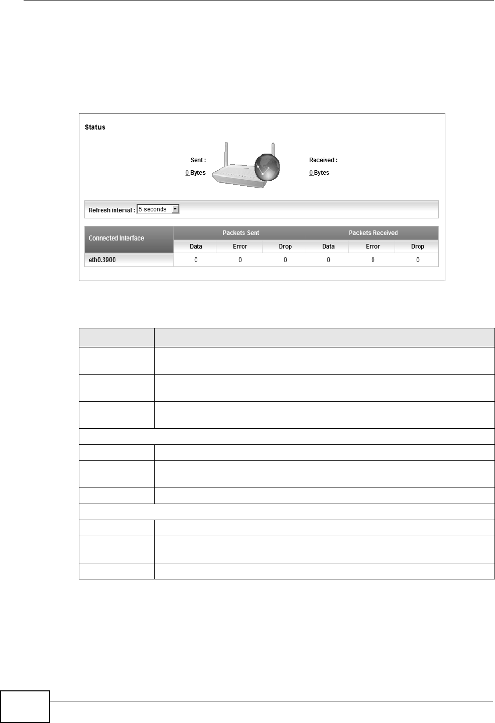
Chapter 18 System Monitor
P-2612HNU(L)-FxF User’s Guide
260
18.2 The WAN Status Screen
Click System Monitor > Traffic Status to open the WAN screen. You can view
the WAN traffic statistics in this screen.
Figure 110 System Monitor > Traffic Status > WAN
The following table describes the fields in this screen.
Table 69 System Monitor > Traffic Status > WAN
LABEL DESCRIPTION
Status This shows the number of bytes received and sent through the WAN
interface of the ZyXEL Device.
Refresh
Interval
Select how often you want the ZyXEL Device to update this screen from
the drop-down list box.
Connected
Interface
This shows the name of the WAN interface that is currently connected.
Packets Sent
Data This indicates the number of transmitted packets on this interface.
Error This indicates the number of frames with errors transmitted on this
interface.
Drop This indicates the number of outgoing packets dropped on this interface.
Packets Received
Data This indicates the number of received packets on this interface.
Error This indicates the number of frames with errors received on this
interface.
Drop This indicates the number of received packets dropped on this interface.
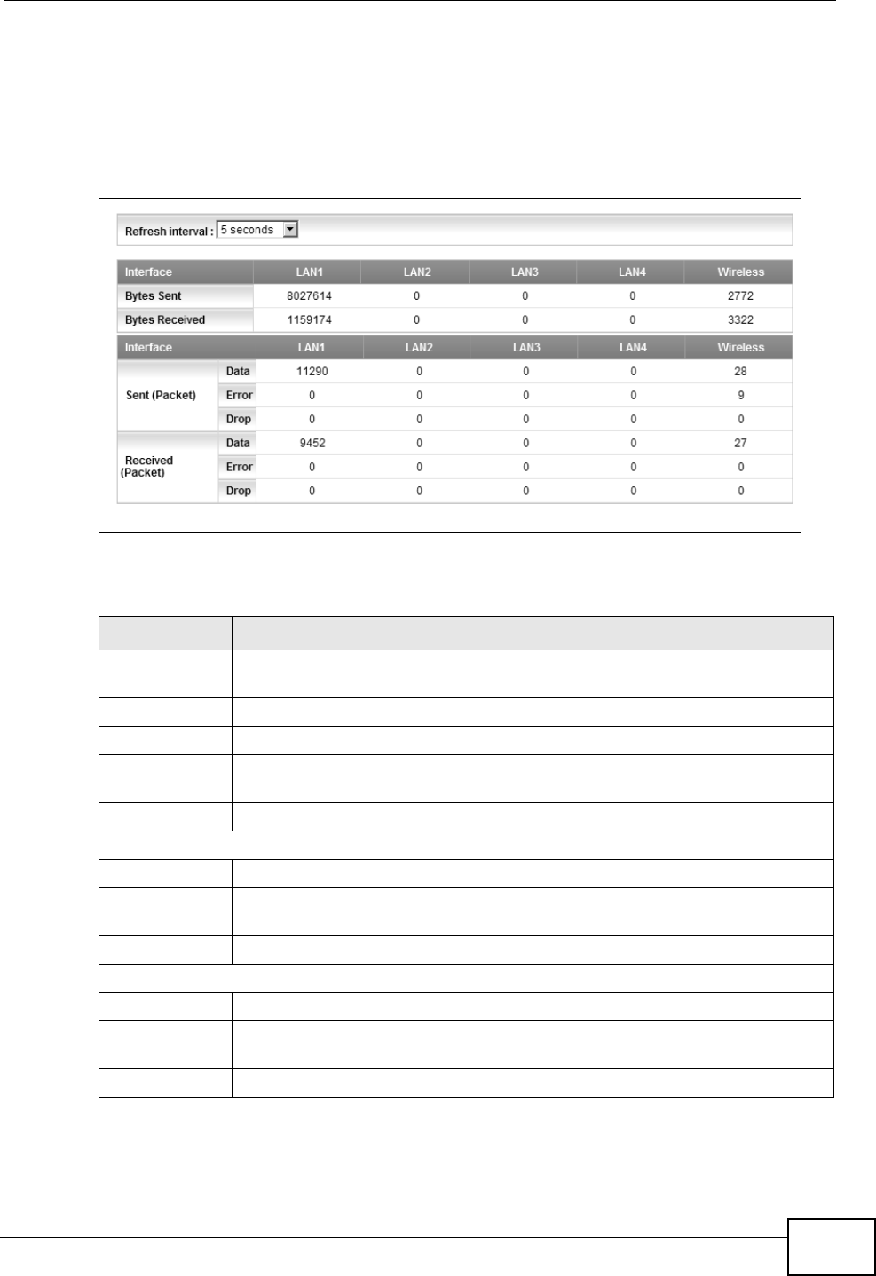
Chapter 18 System Monitor
P-2612HNU(L)-FxF User’s Guide 261
18.3 The LAN Status Screen
Click System Monitor > Traffic Status > LAN to open the following screen. You
can view the LAN traffic statistics in this screen.
Figure 111 System Monitor > Traffic Status > LAN
The following table describes the fields in this screen.
Table 70 System Monitor > Traffic Status > LAN
LABEL DESCRIPTION
Refresh
Interval
Select how often you want the ZyXEL Device to update this screen from
the drop-down list box.
Interface This shows the LAN or WLAN interface.
Bytes Sent This indicates the number of bytes transmitted on this interface.
Bytes
Received
This indicates the number of bytes received on this interface.
Interface This shows the LAN or WLAN interface.
Sent (Packet)
Data This indicates the number of transmitted packets on this interface.
Error This indicates the number of frames with errors transmitted on this
interface.
Drop This indicates the number of outgoing packets dropped on this interface.
Received (Packet)
Data This indicates the number of received packets on this interface.
Error This indicates the number of frames with errors received on this
interface.
Drop This indicates the number of received packets dropped on this interface.
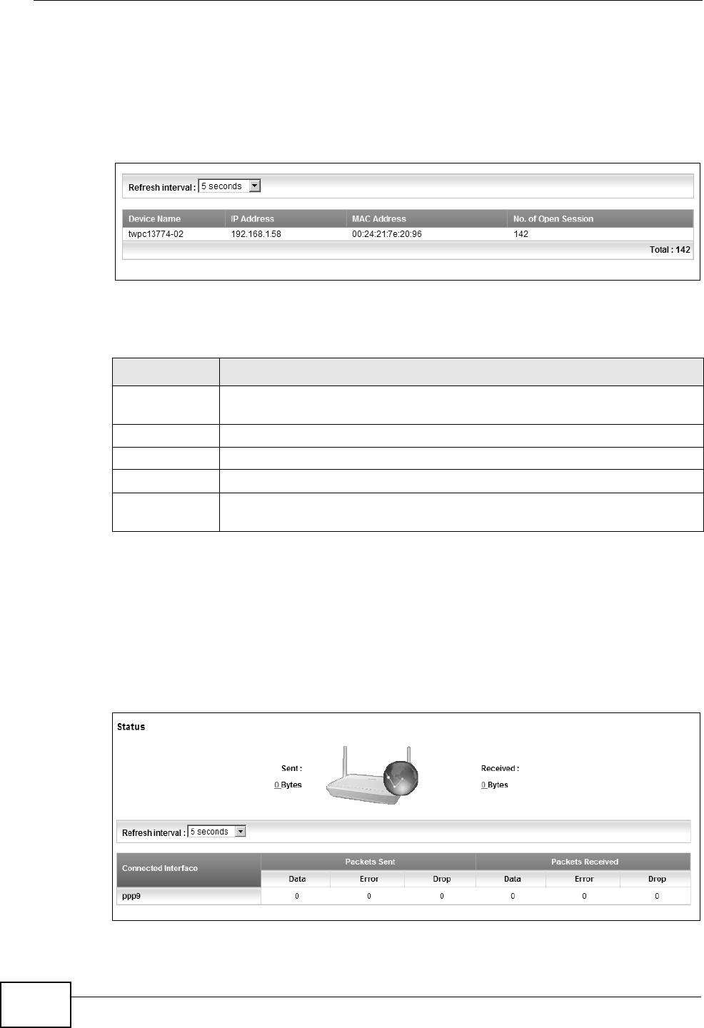
Chapter 18 System Monitor
P-2612HNU(L)-FxF User’s Guide
262
18.4 The NAT Status Screen
Click System Monitor > Traffic Status > NAT to open the following screen. You
can view the NAT status of the ZyXEL Device’s client(s) in this screen.
Figure 112 System Monitor > Traffic Status > NAT
The following table describes the fields in this screen.
18.5 The 3G Backup Status Screen
Click System Monitor > Traffic Status > 3G Backup to open the following
screen. You can view the 3G connection traffic statistics in this screen.
Figure 113 System Monitor > Traffic Status > 3G Backup
Table 71 System Monitor > Traffic Status > NAT
LABEL DESCRIPTION
Refresh
Interval
Select how often you want the ZyXEL Device to update this screen from
the drop-down list box.
Device Name This shows the name of the client.
IP Address This shows the IP address of the client.
MAC Address This shows the MAC address of the client.
No. of Open
Session
This shows the number of NAT sessions used by the client.
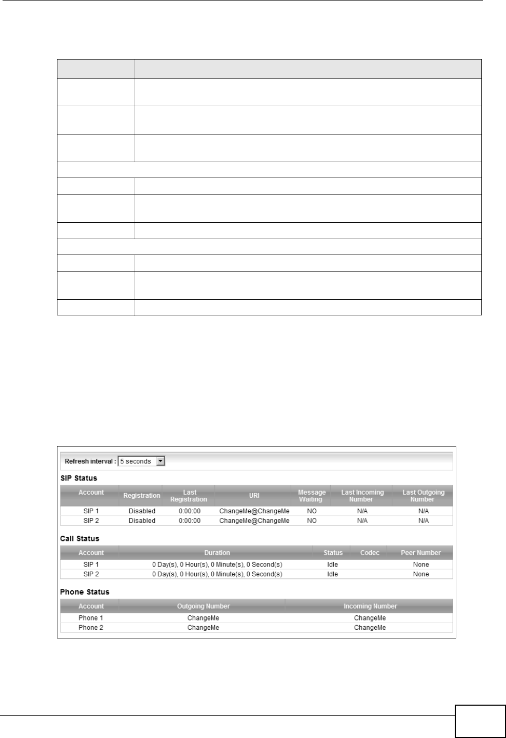
Chapter 18 System Monitor
P-2612HNU(L)-FxF User’s Guide 263
The following table describes the fields in this screen.
18.6 The VoIP Status Screen
Click System Monitor > VoIP Status to open the following screen. You can view
the VoIP traffic statistics in this screen.
Figure 114 System Monitor > VoIP Status
Table 72 System Monitor > Traffic Status > 3G backup
LABEL DESCRIPTION
Status This shows the number of bytes received and sent through the 3G
interface of the ZyXEL Device.
Refresh
Interval
Select how often you want the ZyXEL Device to update this screen from
the drop-down list box.
Connected
Interface
This shows the name of the 3G connection interface that is currently
connected.
Packets Sent
Data This indicates the number of transmitted packets on this interface.
Error This indicates the number of frames with errors transmitted on this
interface.
Drop This indicates the number of outgoing packets dropped on this interface.
Packets Received
Data This indicates the number of received packets on this interface.
Error This indicates the number of frames with errors received on this
interface.
Drop This indicates the number of received packets dropped on this interface.
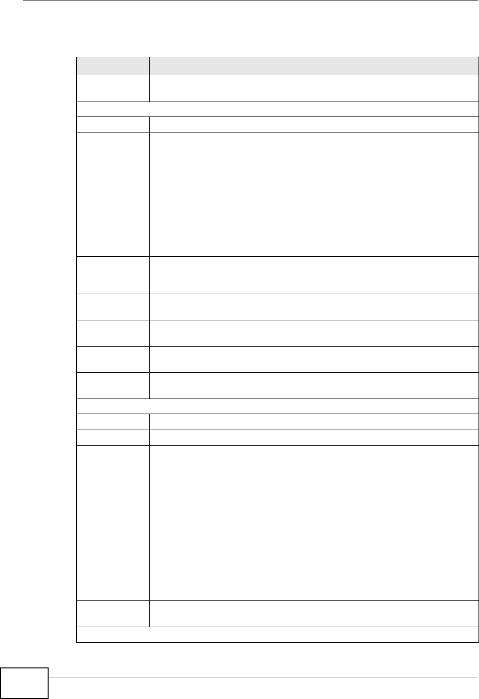
Chapter 18 System Monitor
P-2612HNU(L)-FxF User’s Guide
264
The following table describes the fields in this screen.
Table 73 System Monitor > VoIP Status
LABEL DESCRIPTION
Refresh
Interval
Select how often you want the ZyXEL Device to update this screen from
the drop-down list box.
SIP Status
Account This column displays each SIP account in the ZyXEL Device.
Registration This field displays the current registration status of the SIP account. You
can change this in the Status screen.
Registered - The SIP account is registered with a SIP server.
Not Registered - The last time the ZyXEL Device tried to register the
SIP account with the SIP server, the attempt failed. The ZyXEL Device
automatically tries to register the SIP account when you turn on the
ZyXEL Device or when you activate it.
Inactive - The SIP account is not active. You can activate it in VoIP >
SIP > SIP Account.
Last
Registration
This field displays the last time you successfully registered the SIP
account. The field is blank if you never successfully registered this
account.
URI This field displays the account number and service domain of the SIP
account. You can change these in the VoIP > SIP screens.
Message
Waiting
This field indicates whether or not there are any messages waiting for the
SIP account.
Last Incoming
Number
This field displays the last number that called the SIP account. The field
is blank if no number has ever dialed the SIP account.
Last Outgoing
Number
This field displays the last number the SIP account called. The field is
blank if the SIP account has never dialed a number.
Call Status
Account This column displays each SIP account in the ZyXEL Device.
Duration This field displays how long the current call has lasted.
Status This field displays the current state of the phone call.
Idle - There are no current VoIP calls, incoming calls or outgoing calls
being made.
Dial - The callee’s phone is ringing.
Ring - The phone is ringing for an incoming VoIP call.
Process - There is a VoIP call in progress.
DISC - The callee’s line is busy, the callee hung up or your phone was
left off the hook.
Codec This field displays what voice codec is being used for a current VoIP call
through a phone port.
Peer Number This field displays the SIP number of the party that is currently engaged
in a VoIP call through a phone port.
Phone Status
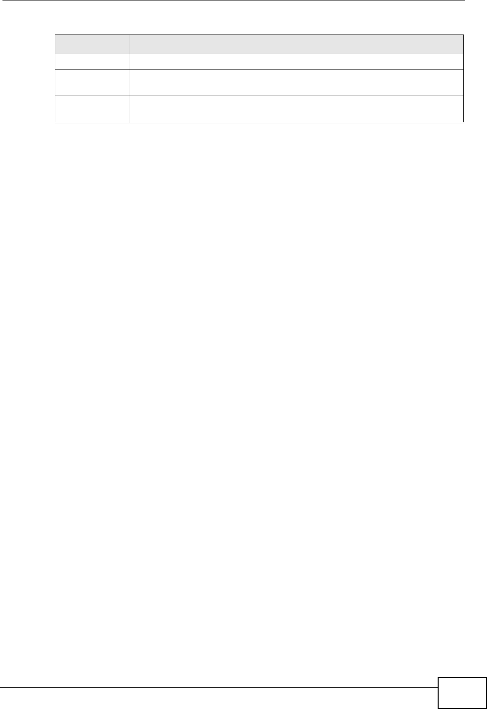
Chapter 18 System Monitor
P-2612HNU(L)-FxF User’s Guide 265
Account This field displays the phone accounts of the ZyXEL Device.
Outgoing
Number
This field displays the SIP number that you use to make calls on this
phone port.
Incoming
Number
This field displays the SIP number that you use to receive calls on this
phone port.
Table 73 System Monitor > VoIP Status (continued)
LABEL DESCRIPTION

Chapter 18 System Monitor
P-2612HNU(L)-FxF User’s Guide
266
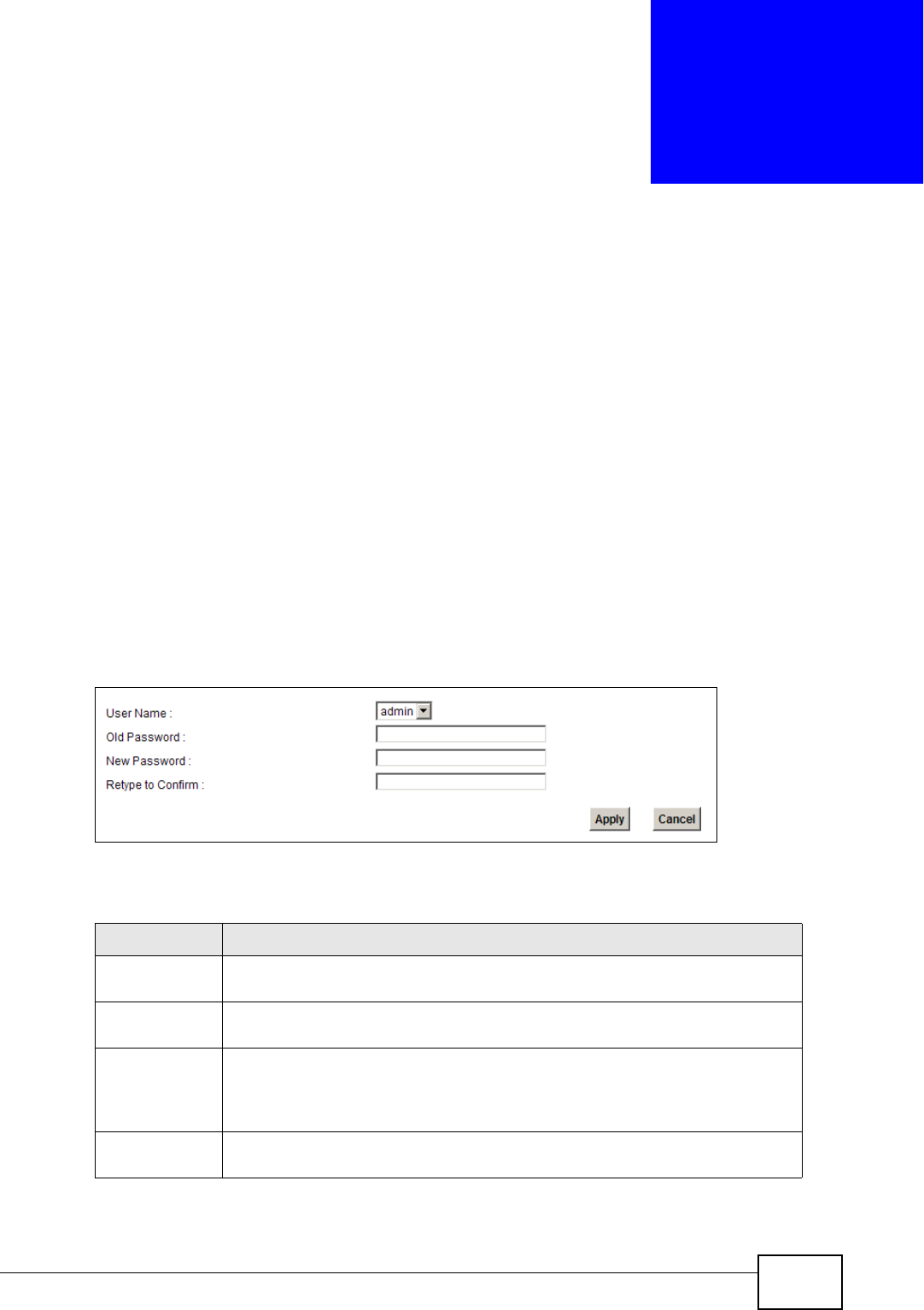
P-2612HNU(L)-FxF User’s Guide 267
CHAPTER 19
User Account
19.1 Overview
You can configure system password for different user accounts in the User
Account screen.
19.2 The User Account Screen
Use the User Account screen to configure system password.
Click Maintenance > User Account to open the following screen.
Figure 115 Maintenance > User Account
The following table describes the labels in this screen.
Table 74 Maintenance > User Account
LABEL DESCRIPTION
User Name You can configure the password for the admin or user account . Select
admin or user from the drop-down list box.
Old Password Type the default password or the existing password you use to access the
system in this field.
New Password Type your new system password (up to 30 characters). Note that as you
type a password, the screen displays a (*) for each character you type.
After you change the password, use the new password to access the
ZyXEL Device.
Retype to
Confirm
Type the new password again for confirmation.
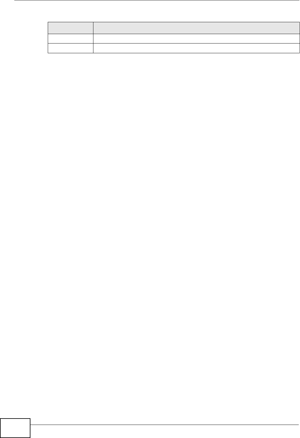
Chapter 19 User Account
P-2612HNU(L)-FxF User’s Guide
268
Apply Click Apply to save your changes.
Cancel Click Cancel to restore your previously saved settings.
Table 74 Maintenance > User Account (continued)
LABEL DESCRIPTION

P-2612HNU(L)-FxF User’s Guide 269
CHAPTER 20
Remote MGMT
20.1 Overview
Remote MGMT allows you to manage your ZyXEL Device from a remote location
through the following interfaces:
• LAN and WLAN
• WAN only
Note: The ZyXEL Device is managed using the web configurator.
20.1.1 What You Need to Know
The following terms and concepts may help as you read this chapter
TR-064
TR-064 is a LAN-Side DSL CPE Configuration protocol defined by the DSL Forum.
TR-064 is built on top of UPnP. It allows the users to use a TR-064 compliant CPE
management application on their computers from the LAN to discover the CPE and
configure user-specific parameters, such as the username and password.
SSH/SCP/SFTP
Secure Shell (SSH) is a secure communication protocol that combines
authentication and data encryption to provide secure encrypted communication
between two hosts over an unsecured network. The following file transfer methods
use SSH:
•Secure Copy (SC) is a secure way of transferring files between computers. It
uses port 22.
•SSH File Transfer Protocol or Secure File Transfer Protocol (SFTP) is an
old way of transferring files between computers. It uses port 22.
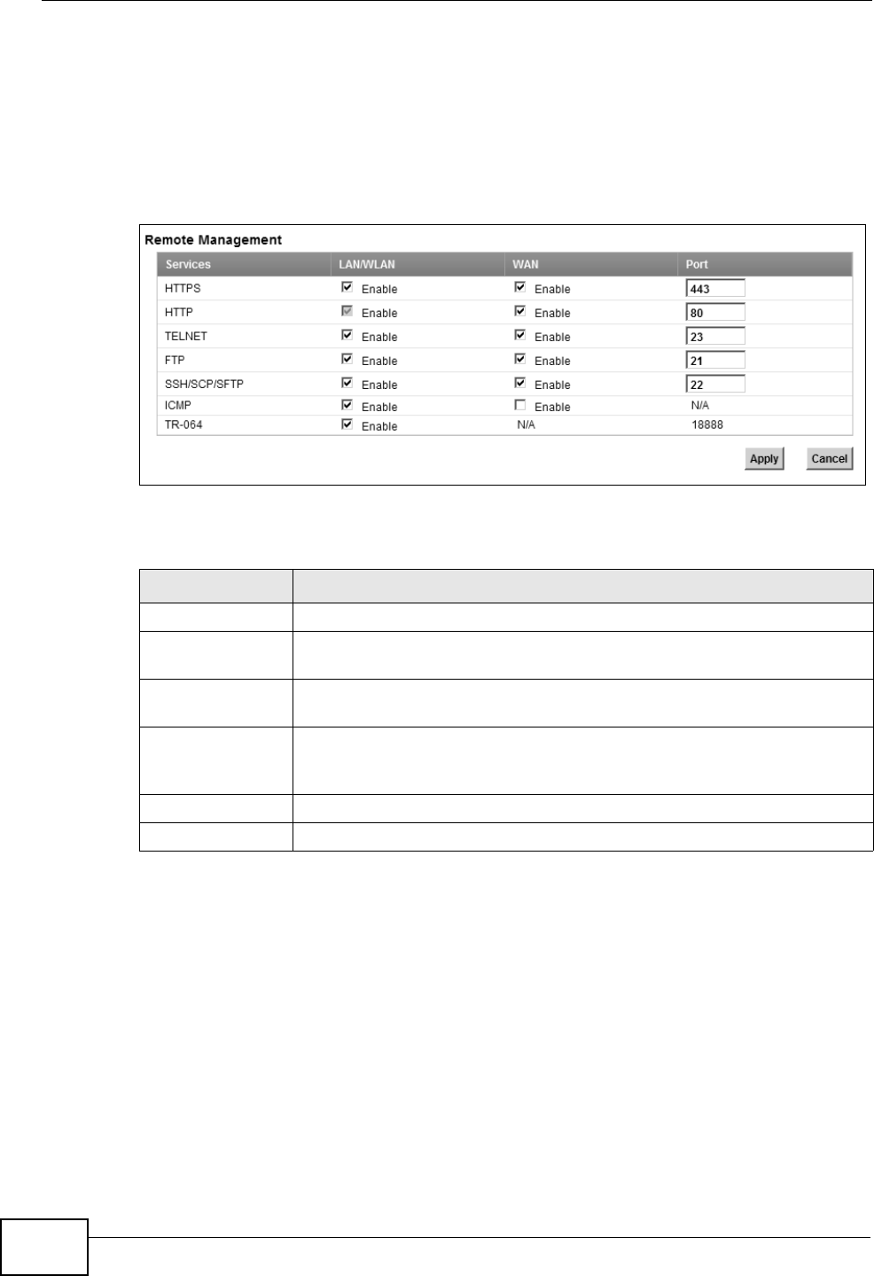
Chapter 20 Remote MGMT
P-2612HNU(L)-FxF User’s Guide
270
20.2 The Remote MGMT Screen
Use this screen to decide what services you may use to access which ZyXEL
Device interface. Click Maintenance > Remote MGMT to open the following
screen.
Figure 116 Maintenance > Remote MGMT
The following table describes the fields in this screen.
Table 75 Maintenance > Remote MGMT
LABEL DESCRIPTION
Services This is the service you may use to access the ZyXEL Device.
LAN/WLAN Select the Enable check box for the corresponding services that you
want to allow access to the ZyXEL Device from the LAN and WLAN.
WAN Select the Enable check box for the corresponding services that you
want to allow access to the ZyXEL Device from the WAN.
Port You may change the server port number for a service if needed,
however you must use the same port number in order to use that
service for remote management.
Apply Click Apply to save your changes.
Cancel Click Cancel to restore your previously saved settings.

P-2612HNU(L)-FxF User’s Guide 271
CHAPTER 21
System
21.1 Overview
You can configure system settings, including the host name, domain name and the
inactivity time-out interval in the System screen.
21.1.1 What You Need to Know
The following terms and concepts may help as you read this chapter.
Domain Name
This is a network address that identifies the owner of a network connection. For
example, in the network address “www.zyxel.com/support/files”, the domain
name is “www.zyxel.com”.
21.2 The System Screen
Use the System screen to configure the system’s host name, domain name, and
inactivity time-out interval.
The Host Name is for identification purposes. However, because some ISPs check
this name you should enter your computer's "Computer Name". Find the system
name of your Windows computer.
In Windows XP, click start, My Computer,View system information and then
click the Computer Name tab. Note the entry in the Full computer name field
and enter it as the ZyXEL Device System Name.
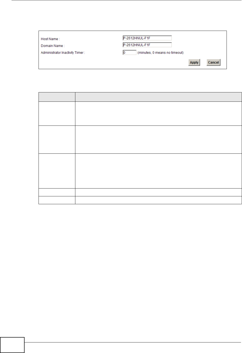
Chapter 21 System
P-2612HNU(L)-FxF User’s Guide
272
Click Maintenance > System to open the following screen.
Figure 117 Maintenance > System
The following table describes the labels in this screen.
Table 76 Maintenance > System
LABEL DESCRIPTION
Host Name Choose a descriptive name for identification purposes. It is
recommended you enter your computer’s “Computer name” in this field.
This name can be up to 30 alphanumeric characters long. Spaces are not
allowed, but dashes “-” and underscores "_" are accepted.
Domain Name Enter the domain name (if you know it) here. If you leave this field blank,
the ISP may assign a domain name via DHCP.
The domain name entered by you is given priority over the ISP assigned
domain name.
Administrator
Inactivity
Timer
Type how many minutes a management session (either via the web
configurator) can be left idle before the session times out. The default is
5 minutes. After it times out you have to log in with your password again.
Very long idle timeouts may have security risks. A value of "0" means a
management session never times out, no matter how long it has been
left idle (not recommended).
Apply Click this to save your changes back to the ZyXEL Device.
Cancel Click this to begin configuring this screen afresh.
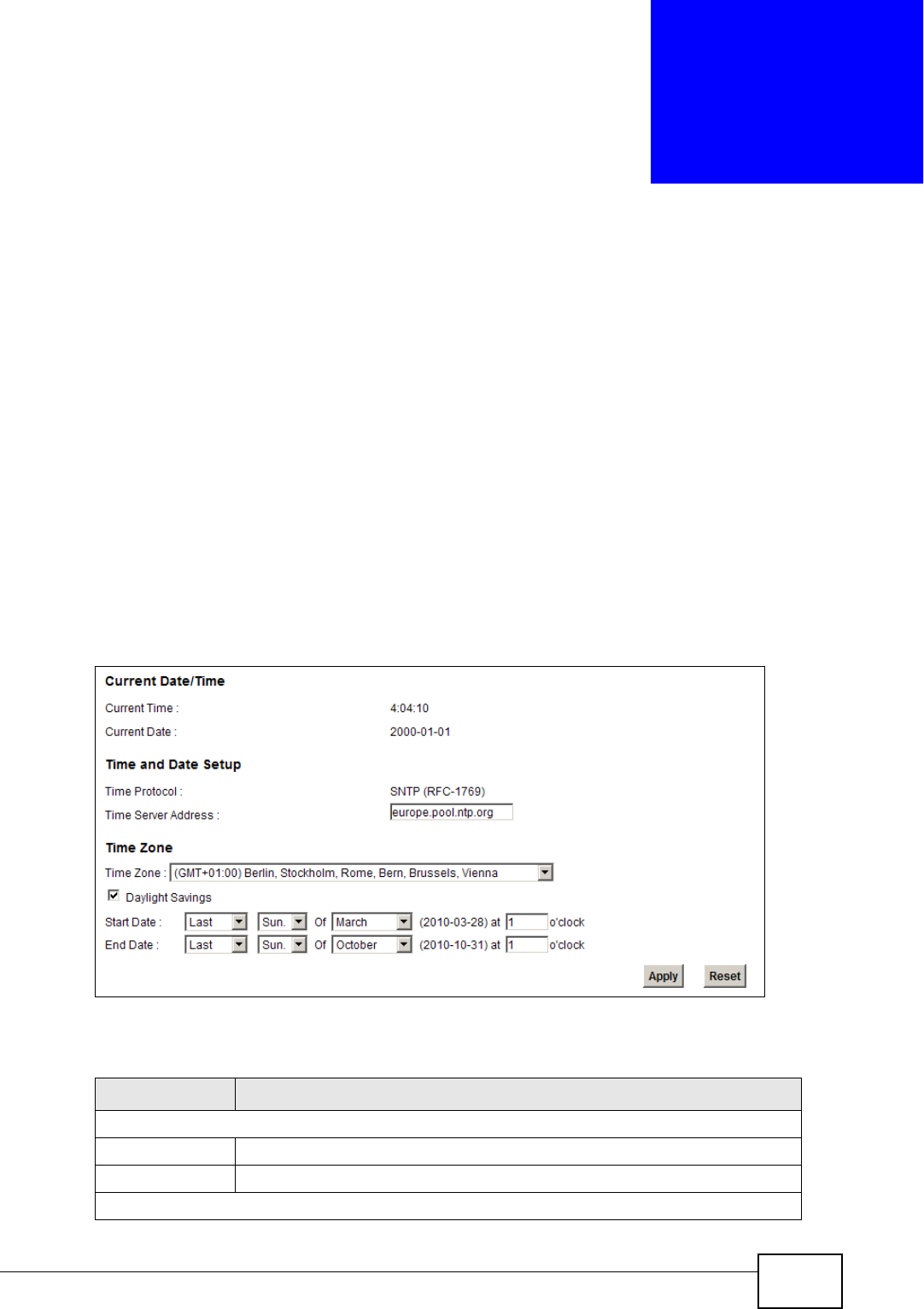
P-2612HNU(L)-FxF User’s Guide 273
CHAPTER 22
Time Setting
22.1 Overview
You can configure the system’s time and date in the Time Setting screen.
22.2 The Time Setting Screen
To change your ZyXEL Device’s time and date, click Maintenance > Time
Setting. The screen appears as shown. Use this screen to configure the ZyXEL
Device’s time based on your local time zone.
Figure 118 Maintenance > Time Setting
The following table describes the fields in this screen.
Table 77 Maintenance > System > Time Setting
LABEL DESCRIPTION
Current Date/Time
Current Time This field displays the time of your ZyXEL Device.
Current Date This field displays the date of your ZyXEL Device.
Time and Date Setup
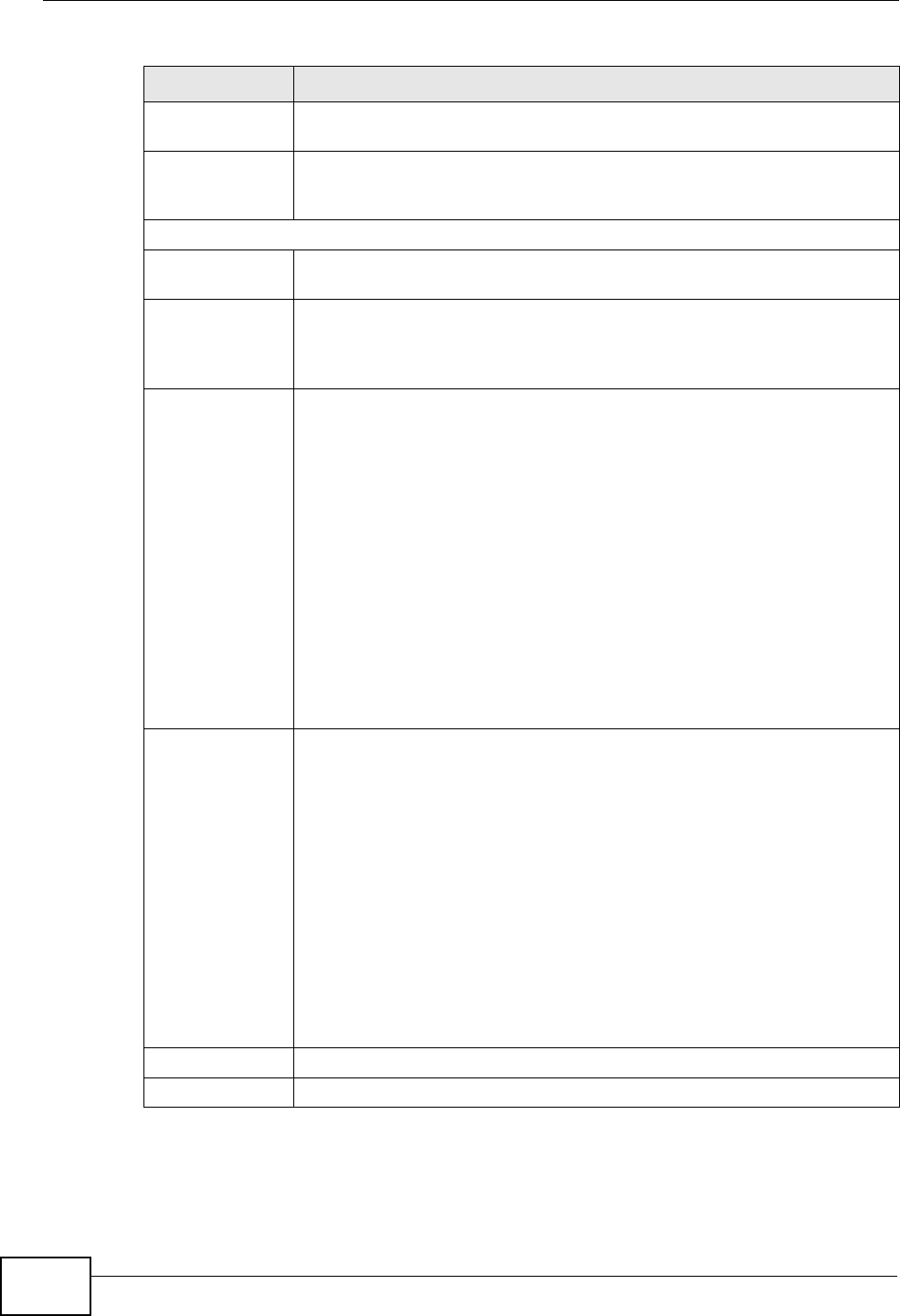
Chapter 22 Time Setting
P-2612HNU(L)-FxF User’s Guide
274
Time Protocol This shows the time service protocol that your time server sends when
you turn on the ZyXEL Device.
Time Server
Address
Enter the IP address or URL (up to 20 extended ASCII characters in
length) of your time server. Check with your ISP/network administrator
if you are unsure of this information.
Time Zone
Time Zone Choose the time zone of your location. This will set the time difference
between your time zone and Greenwich Mean Time (GMT).
Daylight
Savings
Daylight saving is a period from late spring to early fall when many
countries set their clocks ahead of normal local time by one hour to
give more daytime light in the evening.Select this option if you use
Daylight Saving Time.
Start Date Configure the day and time when Daylight Saving Time starts if you
selected Daylight Savings. The o'clock field uses the 24 hour format.
Here are a couple of examples:
Daylight Saving Time starts in most parts of the United States on the
second Sunday of March. Each time zone in the United States starts
using Daylight Saving Time at 2 A.M. local time. So in the United States
you would select Second, Sunday, March and type 2 in the o'clock
field.
Daylight Saving Time starts in the European Union on the last Sunday
of March. All of the time zones in the European Union start using
Daylight Saving Time at the same moment (1 A.M. GMT or UTC). So in
the European Union you would select Last, Sunday, March. The time
you type in the o'clock field depends on your time zone. In Germany
for instance, you would type 2because Germany's time zone is one
hour ahead of GMT or UTC (GMT+1).
End Date Configure the day and time when Daylight Saving Time ends if you
selected Daylight Savings. The o'clock field uses the 24 hour format.
Here are a couple of examples:
Daylight Saving Time ends in the United States on the first Sunday of
November. Each time zone in the United States stops using Daylight
Saving Time at 2 A.M. local time. So in the United States you would
select First, Sunday, November and type 2 in the o'clock field.
Daylight Saving Time ends in the European Union on the last Sunday of
October. All of the time zones in the European Union stop using
Daylight Saving Time at the same moment (1 A.M. GMT or UTC). So in
the European Union you would select Last, Sunday, October. The
time you type in the o'clock field depends on your time zone. In
Germany for instance, you would type 2 because Germany's time zone
is one hour ahead of GMT or UTC (GMT+1).
Apply Click Apply to save your changes.
Reset Click Reset to begin configuring this screen afresh.
Table 77 Maintenance > System > Time Setting (continued)
LABEL DESCRIPTION
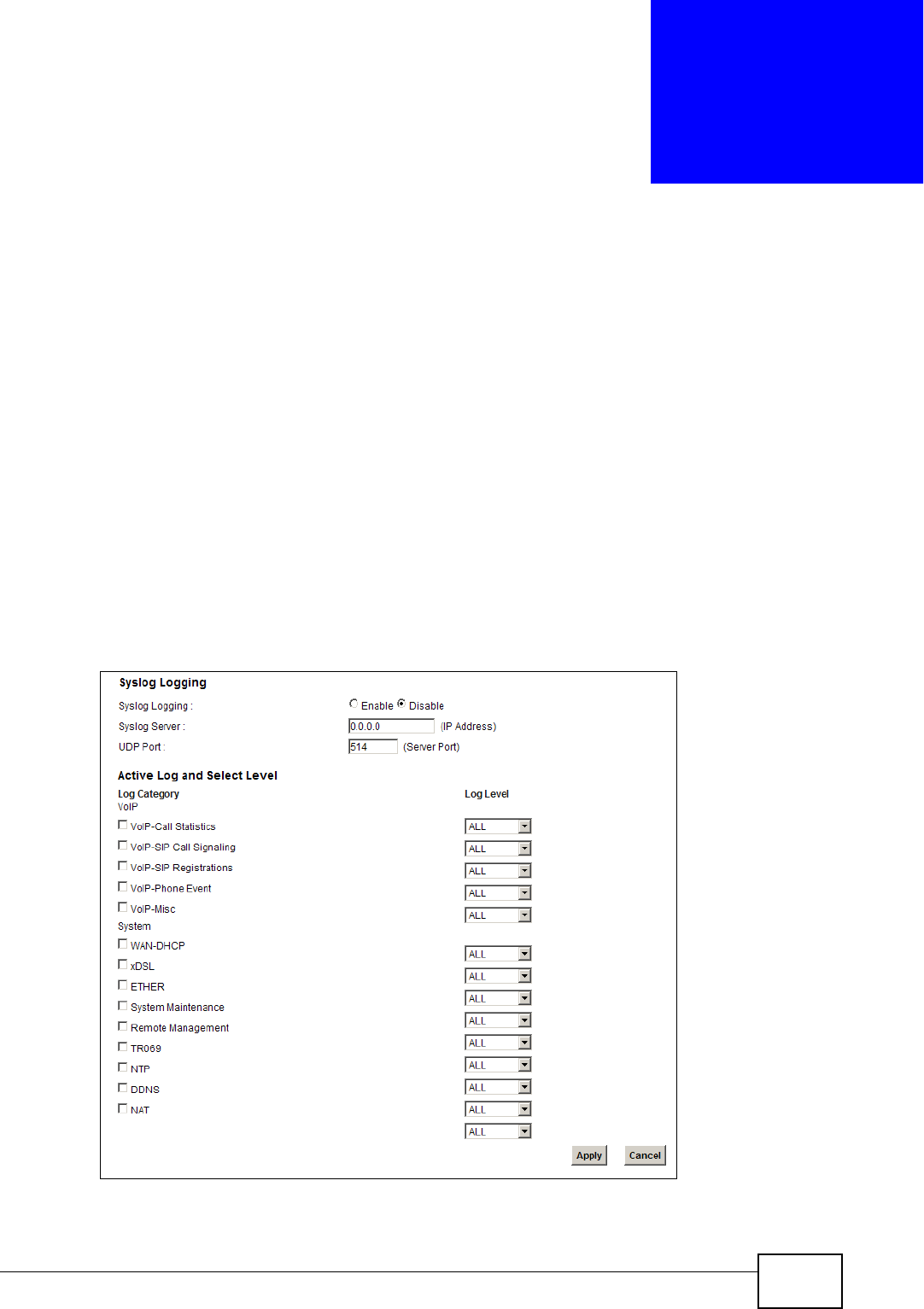
P-2612HNU(L)-FxF User’s Guide 275
CHAPTER 23
Log Setting
23.1 Overview
You can configure where the ZyXEL Device sends logs and which logs and/or
immediate alerts the ZyXEL Device records in the Log Setting screen.
23.2 The Log Setting Screen
To change your ZyXEL Device’s log settings, click Maintenance > Log Setting.
The screen appears as shown.
Figure 119 Maintenance > Log Setting
Chapter 23 Log Setting
P-2612HNU(L)-FxF User’s Guide
276
The following table describes the fields in this screen.
Table 78 Maintenance > Log Setting
LABEL DESCRIPTION
Syslog
Logging
The ZyXEL Device sends a log to an external syslog server. Select the
Enable check box to enable syslog logging.
Syslog Server Enter the server name or IP address of the syslog server that will log the
selected categories of logs.
UDP Port Enter the port number used by the syslog server.
Active Log and Select Level
Log Category Select the categories of logs that you want to record.
Log Level Select the severity level of logs that you want to record. If you want to
record all logs, select ALL.
Apply Click Apply to save your changes.
Cancel Click Cancel to restore your previously saved settings.
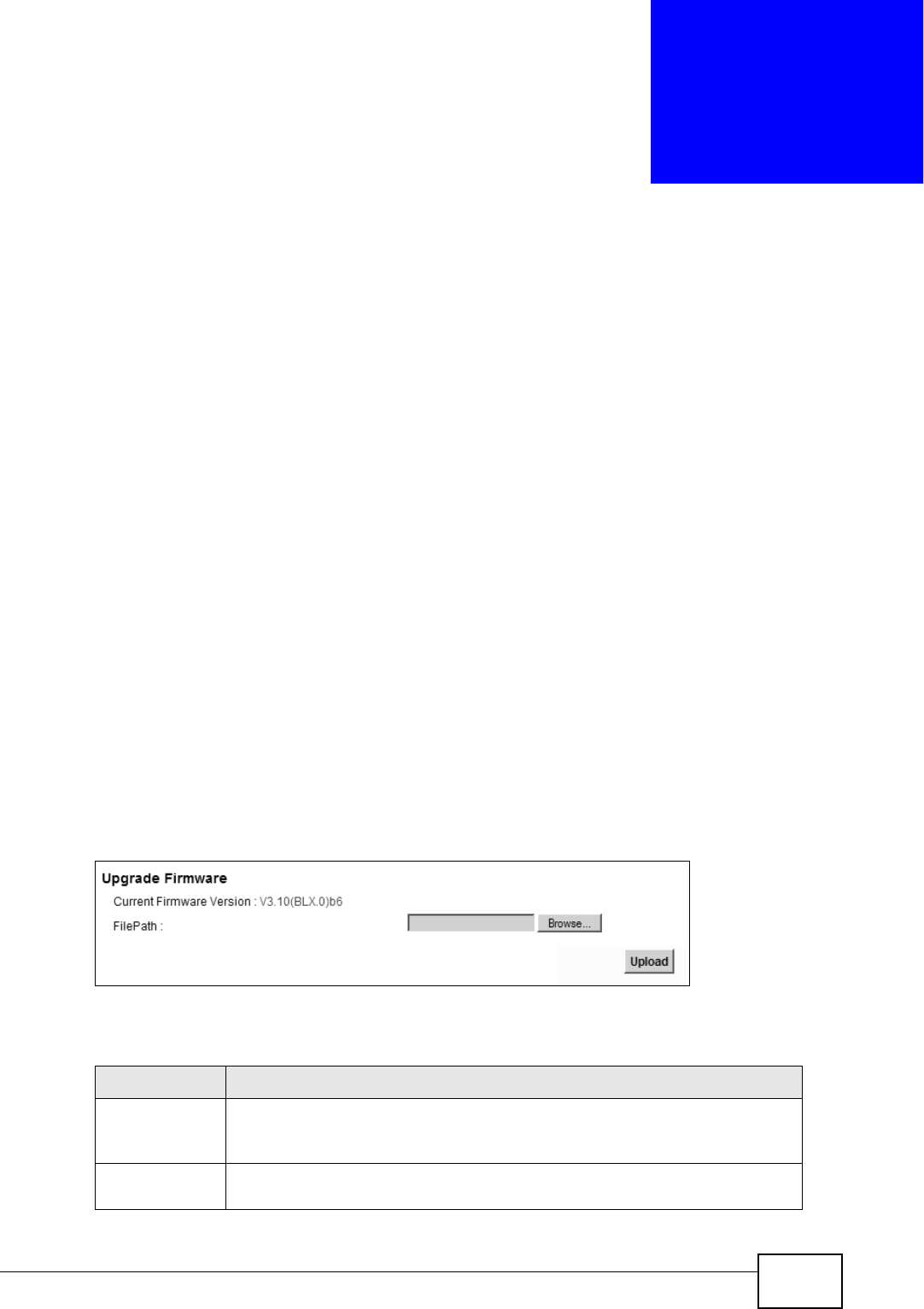
P-2612HNU(L)-FxF User’s Guide 277
CHAPTER 24
Firmware Upgrade
24.1 Overview
This chapter explains how to upload new firmware to your ZyXEL Device. You can
download new firmware releases from your nearest ZyXEL FTP site (or
www.zyxel.com) to use to upgrade your device’s performance.
Only use firmware for your device’s specific model. Refer to the
label on the bottom of your ZyXEL Device.
24.2 The Firmware Upgrade Screen
Click Maintenance > Firmware Upgrade to open the following screen. The
upload process uses HTTP (Hypertext Transfer Protocol) and may take up to two
minutes. After a successful upload, the system will reboot.
Do NOT turn off the ZyXEL Device while firmware upload is in
progress!
Figure 120 Maintenance > Firmware Upgrade
The following table describes the labels in this screen.
Table 79 Maintenance > Firmware Upgrade
LABEL DESCRIPTION
Current
Firmware
Version
This is the present Firmware version.
File Path Type in the location of the file you want to upload in this field or click
Browse ... to find it.
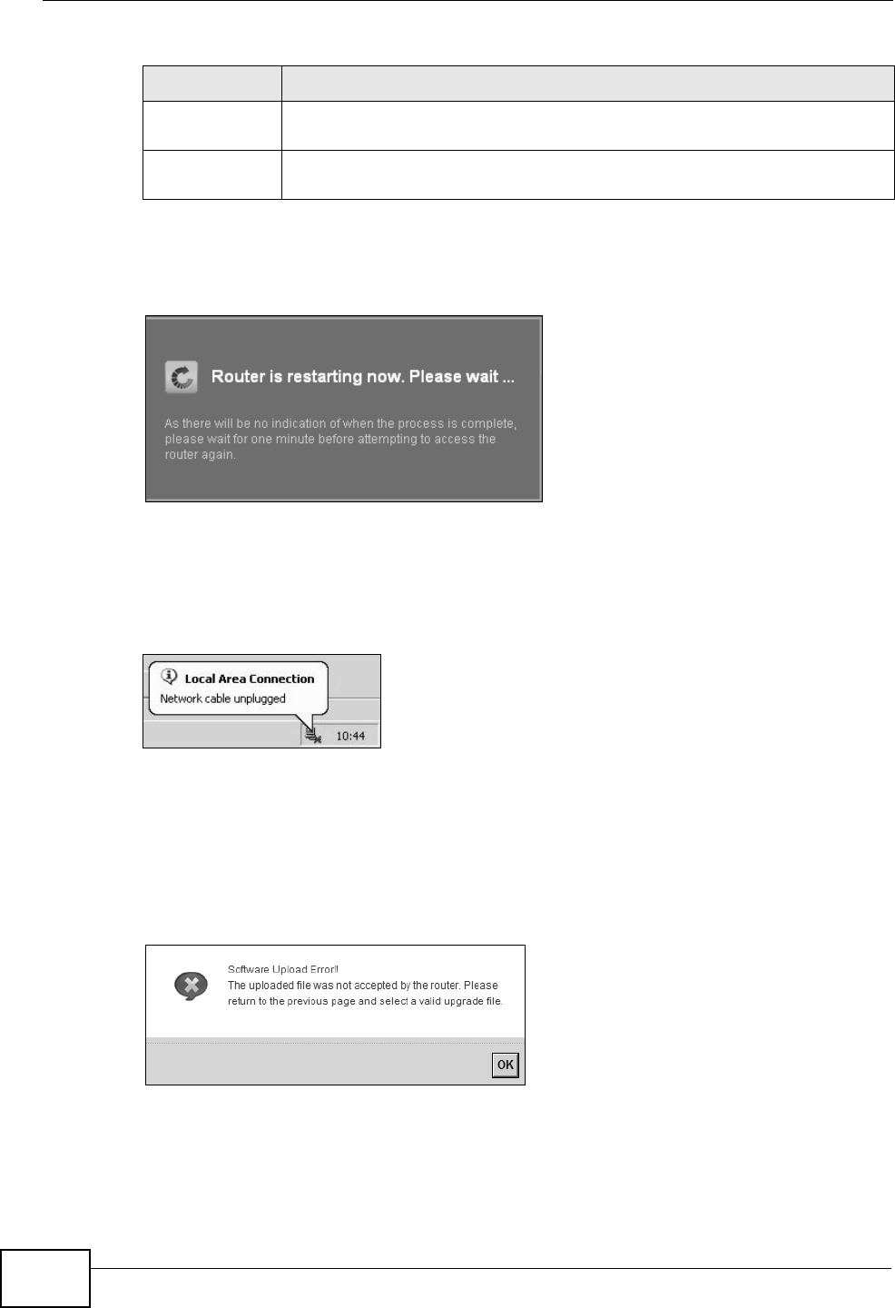
Chapter 24 Firmware Upgrade
P-2612HNU(L)-FxF User’s Guide
278
After you see the firmware updating screen, wait two minutes before logging into
the ZyXEL Device again.
Figure 121 Firmware Uploading
The ZyXEL Device automatically restarts in this time causing a temporary network
disconnect. In some operating systems, you may see the following icon on your
desktop.
Figure 122 Network Temporarily Disconnected
After two minutes, log in again and check your new firmware version in the
Status screen.
If the upload was not successful, an error screen will appear. Click OK to go back
to the Firmware Upgrade screen.
Figure 123 Error Message
Browse... Click this to find the .bin file you want to upload. Remember that you
must decompress compressed (.zip) files before you can upload them.
Upload Click this to begin the upload process. This process may take up to two
minutes.
Table 79 Maintenance > Firmware Upgrade (continued)
LABEL DESCRIPTION
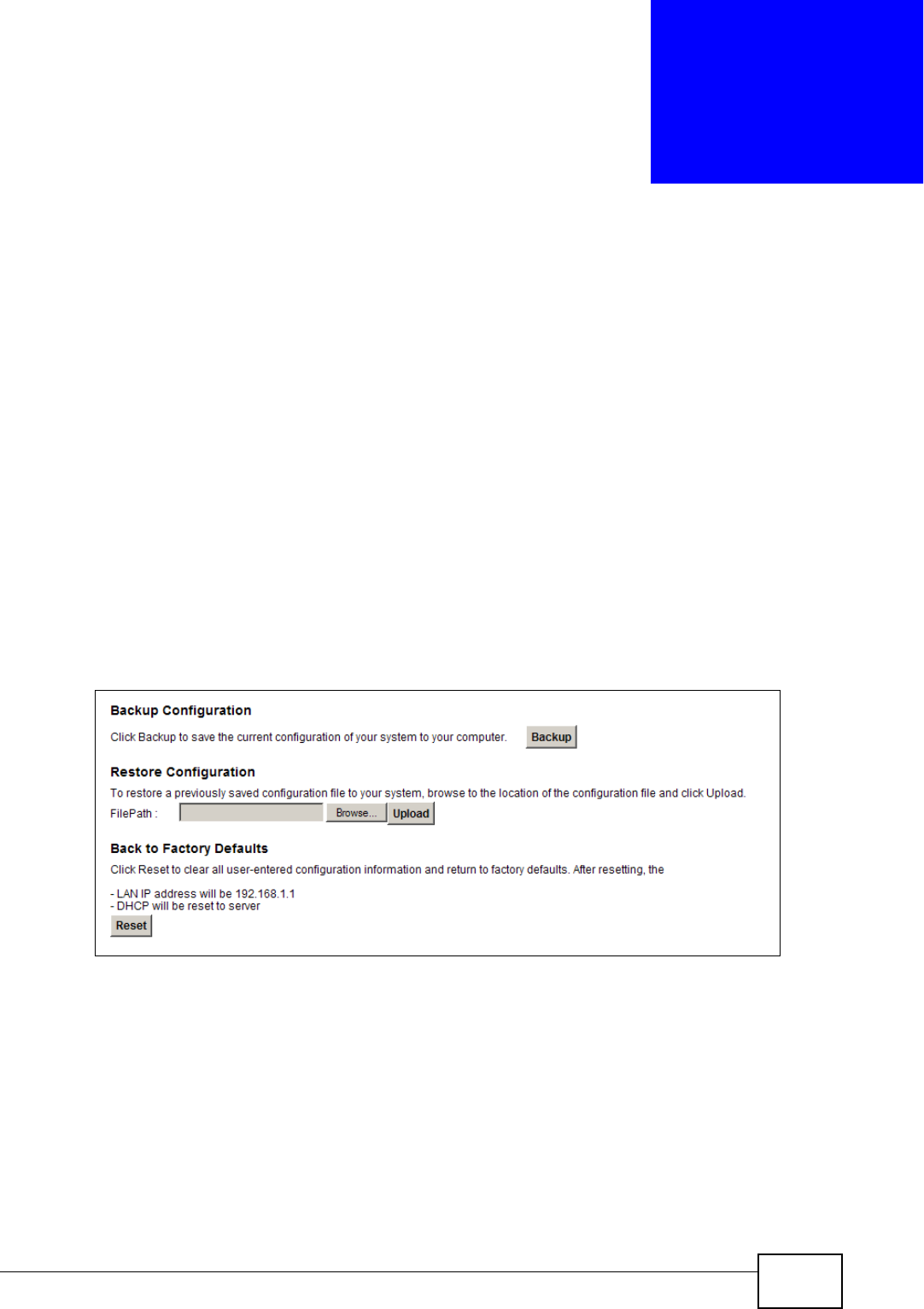
P-2612HNU(L)-FxF User’s Guide 279
CHAPTER 25
Backup/Restore
25.1 Overview
The Backup/Restore screen allows you to backup and restore device
configurations. You can also reset your device settings back to the factory default.
25.2 The Backup/Restore Screen
Click Maintenance > Backup/Restore. Information related to factory defaults,
backup configuration, and restoring configuration appears in this screen, as shown
next.
Figure 124 Maintenance > Backup/Restore
Backup Configuration
Backup Configuration allows you to back up (save) the ZyXEL Device’s current
configuration to a file on your computer. Once your ZyXEL Device is configured
and functioning properly, it is highly recommended that you back up your
configuration file before making configuration changes. The backup configuration
file will be useful in case you need to return to your previous settings.
Click Backup to save the ZyXEL Device’s current configuration to your computer.
Chapter 25 Backup/Restore
P-2612HNU(L)-FxF User’s Guide
280
Restore Configuration
Restore Configuration allows you to upload a new or previously saved
configuration file from your computer to your ZyXEL Device.
Do not turn off the ZyXEL Device while configuration file upload is
in progress.
After the ZyXEL Device configuration has been restored successfully, the login
screen appears. Login again to restart the ZyXEL Device.
The ZyXEL Device automatically restarts in this time causing a temporary network
disconnect. In some operating systems, you may see the following icon on your
desktop.
Figure 125 Network Temporarily Disconnected
If you restore the default configuration, you may need to change the IP address of
your computer to be in the same subnet as that of the default device IP address
(192.168.1.1). See Appendix B on page 317 for details on how to set up your
computer’s IP address.
If the upload was not successful, an error screen will appear. Click OK to go back
to the Configuration screen.
Table 80 Restore Configuration
LABEL DESCRIPTION
File Path Type in the location of the file you want to upload in this field or click
Browse ... to find it.
Browse... Click this to find the file you want to upload. Remember that you must
decompress compressed (.ZIP) files before you can upload them.
Upload Click this to begin the upload process.
Reset Click this to reset your device settings back to the factory default.
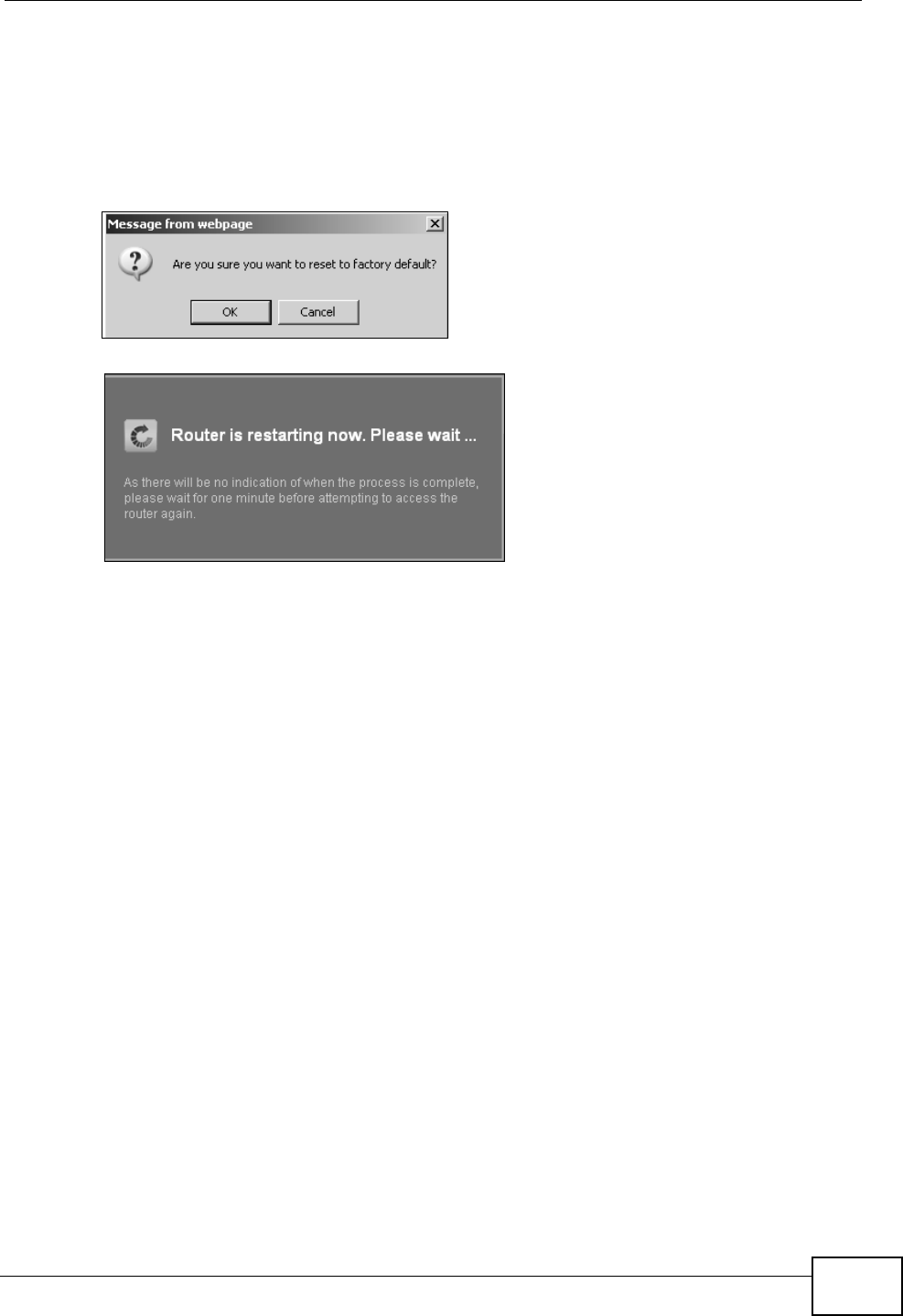
Chapter 25 Backup/Restore
P-2612HNU(L)-FxF User’s Guide 281
Reset to Factory Defaults
Click the Reset button to clear all user-entered configuration information and
return the ZyXEL Device to its factory defaults. The following warning screen
appears.
Figure 126 Reset Warning Message
Figure 127 Reset In Process Message
You can also press the RESET button on the rear panel to reset the factory
defaults of your ZyXEL Device. Refer to Section 1.7 on page 28 for more
information on the RESET button.
25.3 The Reboot Screen
System restart allows you to reboot the ZyXEL Device remotely without turning
the power off. You may need to do this if the ZyXEL Device hangs, for example.
Click Maintenance > Reboot. Click the Reboot button to have the ZyXEL Device
reboot. This does not affect the ZyXEL Device's configuration.

Chapter 25 Backup/Restore
P-2612HNU(L)-FxF User’s Guide
282
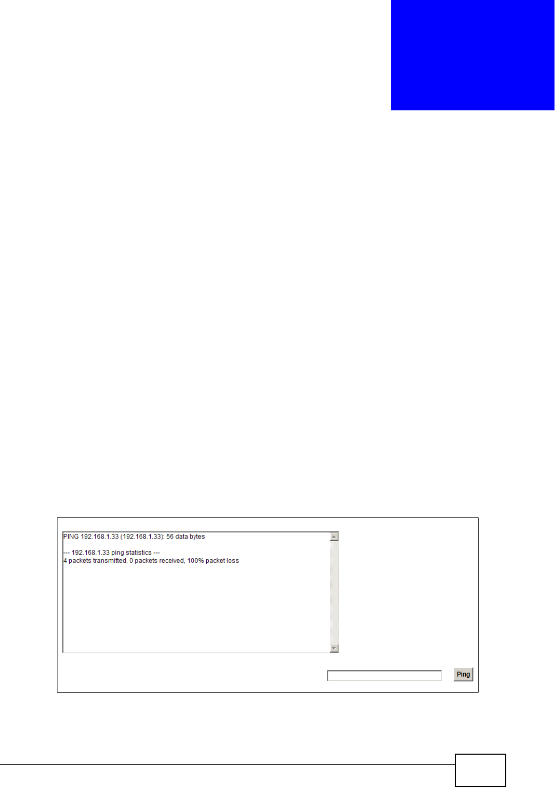
P-2612HNU(L)-FxF User’s Guide 283
CHAPTER 26
Diagnostic
26.1 Overview
You can use different diagnostic methods to test a connection and see the detailed
information. These read-only screens display information to help you identify
problems with the ZyXEL Device.
26.1.1 What You Can Do in this Chapter
• Use the Ping screen to ping an IP address and see the ping statistics (Section
26.2 on page 283).
• Use the DSL Line screen to check or reset your DSL connection (Section 26.3
on page 284).
26.2 The Ping Screen
Use this screen to ping an IP address. Click Maintenance > Diagnostic to open
the Ping screen shown next.
Figure 128 Maintenance > Diagnostic > Ping
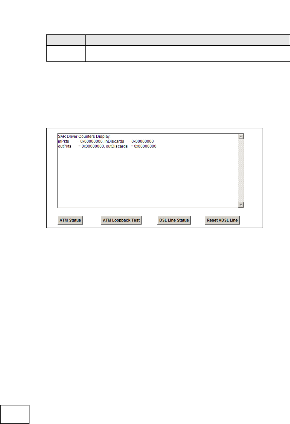
Chapter 26 Diagnostic
P-2612HNU(L)-FxF User’s Guide
284
The following table describes the fields in this screen.
26.3 The DSL Line Screen
Click Maintenance > Diagnostic > DSL Line to open the screen shown next.
Figure 129 Maintenance > Diagnostic > DSL Line
Table 81 Maintenance > Diagnostic > Ping
LABEL DESCRIPTION
Ping Type the IP address of a computer that you want to ping in order to test a
connection. Click Ping and the ping statistics will show in the diagnostic .
Chapter 26 Diagnostic
P-2612HNU(L)-FxF User’s Guide 285
The following table describes the fields in this screen.
Table 82 Maintenance > Diagnostic > DSL Line
ITEM DESCRIPTION
ATM
Status
Click this button to view your DSL connection’s Asynchronous Transfer Mode
(ATM) statistics. ATM is a networking technology that provides high-speed
data transfer. ATM uses fixed-size packets of information called cells. With
ATM, a high QoS (Quality of Service) can be guaranteed.
The (Segmentation and Reassembly) SAR driver translates packets into ATM
cells. It also receives ATM cells and reassembles them into packets.
These counters are set back to zero whenever the device starts up.
inPkts is the number of good ATM cells that have been received.
inDiscards is the number of received ATM cells that were rejected.
outPkts is the number of ATM cells that have been sent.
outDiscards is the number of ATM cells sent that were rejected.
ATM
Loopback
Test
Click this button to start the ATM loopback test. Make sure you have
configured at least one PVC with proper VPIs/VCIs before you begin this test.
The ZyXEL Device sends an OAM F5 packet to the DSLAM/ATM switch and
then returns it (loops it back) to the ZyXEL Device. The ATM loopback test is
useful for troubleshooting problems with the DSLAM and ATM network.

Chapter 26 Diagnostic
P-2612HNU(L)-FxF User’s Guide
286
DSL Line
Status
Click this button to view statistics about the DSL connections.
1. noise margin downstream is the signal to noise ratio for the
downstream part of the connection (coming into the ZyXEL Device from
the ISP). It is measured in decibels. The higher the number the more
signal and less noise there is.
2. output power upstream is the amount of power (in decibels) that the
ZyXEL Device is using to transmit to the ISP.
3. attenuation downstream is the reduction in amplitude (in decibels) of
the DSL signal coming into the ZyXEL Device from the ISP.
Discrete Multi-Tone (DMT) modulation divides up a line’s bandwidth into sub-
carriers (sub-channels) of 4.3125 KHz each called tones. The rest of the
display is the line’s bit allocation. This is displayed as the number (in
hexadecimal format) of bits transmitted for each tone. This can be used to
determine the quality of the connection, whether a given sub-carrier loop has
sufficient margins to support certain ADSL transmission rates, and possibly
to determine whether particular specific types of interference or line
attenuation exist. Refer to the ITU-T G.992.1 recommendation for more
information on DMT.
The better (or shorter) the line, the higher the number of bits transmitted for
a DMT tone. The maximum number of bits that can be transmitted per DMT
tone is 15. There will be some tones without any bits as there has to be
space between the upstream and downstream channels.
Reset
ADSL Line
Click this button to reinitialize the ADSL line. The large text box above then
displays the progress and results of this operation, for example:
"Start to reset ADSL
Loading ADSL modem F/W...
Reset ADSL Line Successfully!"
Table 82 Maintenance > Diagnostic > DSL Line (continued)
ITEM DESCRIPTION

P-2612HNU(L)-FxF User’s Guide 287
CHAPTER 27
Troubleshooting
27.1 Overview
This chapter offers some suggestions to solve problems you might encounter. The
potential problems are divided into the following categories.
•Power, Hardware Connections, and LEDs
•ZyXEL Device Access and Login
•Internet Access
•Wireless Internet Access
•Phone Calls and VoIP
•USB Device Connection
•UPnP
27.2 Power, Hardware Connections, and LEDs
The ZyXEL Device does not turn on. None of the LEDs turn on.
1Make sure the ZyXEL Device is turned on.
2Make sure you are using the power adaptor or cord included with the ZyXEL
Device.
3Make sure the power adaptor or cord is connected to the ZyXEL Device and
plugged in to an appropriate power source. Make sure the power source is turned
on.
4Turn the ZyXEL Device off and on.
5If the problem continues, contact the vendor.

Chapter 27 Troubleshooting
P-2612HNU(L)-FxF User’s Guide
288
One of the LEDs does not behave as expected.
1Make sure you understand the normal behavior of the LED. See Section 1.6 on
page 26.
2Check the hardware connections. See the Quick Start Guide.
3Inspect your cables for damage. Contact the vendor to replace any damaged
cables.
4Turn the ZyXEL Device off and on.
5If the problem continues, contact the vendor.
27.3 ZyXEL Device Access and Login
I forgot the IP address for the ZyXEL Device.
1The default IP address is 192.168.1.1.
2If you changed the IP address and have forgotten it, you might get the IP address
of the ZyXEL Device by looking up the IP address of the default gateway for your
computer. To do this in most Windows computers, click Start > Run, enter cmd,
and then enter ipconfig. The IP address of the Default Gateway might be the IP
address of the ZyXEL Device (it depends on the network), so enter this IP address
in your Internet browser.
3If this does not work, you have to reset the device to its factory defaults. See
Section 1.7 on page 28.
I forgot the password.
1The default admin password is 1234 and the default user password is user.
2If this does not work, you have to reset the device to its factory defaults. See
Section 1.7 on page 28.

Chapter 27 Troubleshooting
P-2612HNU(L)-FxF User’s Guide 289
I cannot see or access the Login screen in the web configurator.
1Make sure you are using the correct IP address.
• The default IP address is 192.168.1.1.
• If you changed the IP address (Section on page 162), use the new IP
address.
• If you changed the IP address and have forgotten it, see the troubleshooting
suggestions for I forgot the IP address for the ZyXEL Device.
2Check the hardware connections, and make sure the LEDs are behaving as
expected. See the Quick Start Guide.
3Make sure your Internet browser does not block pop-up windows and has
JavaScript and Java enabled. See Appendix C on page 347.
4Reset the device to its factory defaults, and try to access the ZyXEL Device with
the default IP address. See Section 1.7 on page 28.
5If the problem continues, contact the network administrator or vendor, or try one
of the advanced suggestions.
Advanced Suggestions
• Try to access the ZyXEL Device using another service, such as Telnet. If you can
access the ZyXEL Device, check the remote management settings and firewall
rules to find out why the ZyXEL Device does not respond to HTTP.
• If your computer is connected to the WAN port or is connected wirelessly, use a
computer that is connected to a ETHERNET port.
I can see the Login screen, but I cannot log in to the ZyXEL Device.
1Make sure you have entered the user name and password correctly. The default
user name is admin. These fields are case-sensitive, so make sure [Caps Lock] is
not on.
2You cannot log in to the web configurator while someone is using Telnet to access
the ZyXEL Device. Log out of the ZyXEL Device in the other session, or ask the
person who is logged in to log out.
3Turn the ZyXEL Device off and on.

Chapter 27 Troubleshooting
P-2612HNU(L)-FxF User’s Guide
290
4If this does not work, you have to reset the device to its factory defaults. See
Section 27.2 on page 287.
I cannot Telnet to the ZyXEL Device.
See the troubleshooting suggestions for I cannot see or access the Login screen in
the web configurator. Ignore the suggestions about your browser.
I cannot use FTP to upload / download the configuration file. / I cannot use FTP to
upload new firmware.
See the troubleshooting suggestions for I cannot see or access the Login screen in
the web configurator. Ignore the suggestions about your browser.
27.4 Internet Access
I cannot access the Internet.
1Check the hardware connections, and make sure the LEDs are behaving as
expected. See the Quick Start Guide and Section 1.6 on page 26.
2Make sure you entered your ISP account information correctly. These fields are
case-sensitive, so make sure [Caps Lock] is not on.
3If you are trying to access the Internet wirelessly, make sure the wireless settings
in the wireless client are the same as the settings in the AP.
4If you are trying to access the Internet wirelessly, make sure you have enabled
the wireless LAN by the WPS/WLAN button or the Network Setting > Wireless
> General screen.
5Disconnect all the cables from your device, and follow the directions in the Quick
Start Guide again.
6If the problem continues, contact your ISP.

Chapter 27 Troubleshooting
P-2612HNU(L)-FxF User’s Guide 291
I cannot access the Internet through a DSL connection.
1Check if you set the DSL/WAN switch (on the back of the ZyXEL Device) to the
DSL side to have the ZyXEL Device use the DSL port for Internet access.
2Make sure you configured a proper DSL WAN connection with the Internet account
information provided by your ISP.
3If you set up a WAN connection using bridging service (all LAN ports and WLAN
BSSs are bridged to one WAN connection), make sure you turn off the DHCP
feature in the Home Networking screen to have the clients get WAN IP
addresses directly from your ISP’s DHCP server.
I cannot access the Internet through an Ethernet WAN connection.
1Check if you set the DSL/WAN switch (on the back of the ZyXEL Device) to the
WAN side to have the ZyXEL Device use the Ethernet WAN port for Internet
access.
2Make sure you connect the Ethernet WAN port to a DSL modem or router in your
network.
3Make sure you configured a proper Ethernet WAN connection with the Internet
account information provided by your ISP.
4If you set up a WAN connection using bridging service (all LAN ports and WLAN
BSSs are bridged to one WAN connection), make sure you turn off the DHCP
feature in the Home Networking screen to have the clients get WAN IP
addresses directly from your ISP’s DHCP server.
I cannot connect to the Internet using a second DSL connection.
ADSL and VDSL connections cannot work at the same time. You can only use one
type of DSL connection, either ADSL or VDSL connection at one time.
I cannot create multiple connections of the same type.

Chapter 27 Troubleshooting
P-2612HNU(L)-FxF User’s Guide
292
Your WAN interface must enable VLAN and fill each WAN connection with different
VLAN IDs.
I cannot access the Internet anymore. I had access to the Internet (with the ZyXEL
Device), but my Internet connection is not available anymore.
1Check the hardware connections, and make sure the LEDs are behaving as
expected. See the Quick Start Guide and Section 1.6 on page 26.
2Turn the ZyXEL Device off and on.
3If the problem continues, contact your ISP.
The Internet connection is slow or intermittent.
1There might be a lot of traffic on the network. Look at the LEDs, and check Section
1.6 on page 26. If the ZyXEL Device is sending or receiving a lot of information,
try closing some programs that use the Internet, especially peer-to-peer
applications.
2Turn the ZyXEL Device off and on.
3If the problem continues, contact the network administrator or vendor, or try one
of the advanced suggestions.
Advanced Suggestions
• Check the settings for QoS. If it is disabled, you might consider activating it. If it
is enabled, you might consider raising or lowering the priority for some
applications.
27.5 Wireless Internet Access
What factors may cause intermittent or unstabled wireless connection? How can I
solve this problem?
The following factors may cause interference:

Chapter 27 Troubleshooting
P-2612HNU(L)-FxF User’s Guide 293
• Obstacles: walls, ceilings, furniture, and so on.
• Building Materials: metal doors, aluminum studs.
• Electrical devices: microwaves, monitors, electric motors, cordless phones, and
other wireless devices.
To optimize the speed and quality of your wireless connection, you can:
• Move your wireless device closer to the AP if the signal strength is low.
• Reduce wireless interference that may be caused by other wireless networks or
surrounding wireless electronics such as cordless phones.
• Place the AP where there are minimum obstacles (such as walls and ceilings)
between the AP and the wireless client.
• Reduce the number of wireless clients connecting to the same AP
simultaneously, or add additional APs if necessary.
• Try closing some programs that use the Internet, especially peer-to-peer
applications. If the wireless client is sending or receiving a lot of information, it
may have too many programs open that use the Internet.
• Position the antennas for best reception. If the AP is placed on a table or floor,
point the antennas upwards. If the AP is placed at a high position, point the
antennas downwards. Try pointing the antennas in different directions and
check which provides the strongest signal to the wireless clients.
27.6 Phone Calls and VoIP
The telephone port won’t work or the telephone lacks a dial tone.
1Check the telephone connections and telephone wire.
I can access the Internet, but cannot make VoIP calls.
1The PHONE light should come on. Make sure that your telephone is connected to
the PHONE port.
2You can also check the VoIP status in the System Info screen.
3If the VoIP settings are correct, use speed dial to make peer-to-peer calls. If you
can make a call using speed dial, there may be something wrong with the SIP
server, contact your VoIP service provider.

Chapter 27 Troubleshooting
P-2612HNU(L)-FxF User’s Guide
294
27.7 USB Device Connection
The ZyXEL Device fails to detect my USB device.
1Disconnect the USB device.
2Reboot the ZyXEL Device.
3If you are connecting a USB hard drive that comes with an external power supply,
make sure it is connected to an appropriate power source that is on.
4Re-connect your USB device to the ZyXEL Device.
27.8 UPnP
When using UPnP and the ZyXEL Device reboots, my computer cannot detect
UPnP and refresh My Network Places > Local Network.
1Disconnect the Ethernet cable from the ZyXEL Device’s LAN port or from your
computer.
2Re-connect the Ethernet cable.
The Local Area Connection icon for UPnP disappears in the screen.
Restart your computer.
I cannot open special applications such as white board, file transfer and video
when I use the MSN messenger.
1Wait more than three minutes.
2Restart the applications.

P-2612HNU(L)-FxF User’s Guide 295
CHAPTER 28
Product Specifications
The following tables summarize the ZyXEL Device’s hardware and firmware
features.
Hardware Specifications
Table 83 Hardware Specifications
Dimensions 256 (W) x 145 (D) x 40 (H) mm
Weight 457 g
Power Specification 12V 1.5A DC
Built-in Switch Four auto-negotiating, auto MDI/MDI-X 10/100 Mbps RJ-45
Ethernet ports
DSL Port P-2612HNU(L)-F1F: One RJ-11 DSL port
P-2612HNU(L)-F3F: One RJ-45 DSL port
WAN Port One RJ-45 WAN port
PHONE Ports 2 RJ-11 FXS POTS ports
Line Port (“L” models
only)
One FXO (Foreign Exchange Office) lifeline port
RESET Button Restores factory defaults
WLAN/WPS Button 1 second: Turn on or off WLAN
5 seconds: Start WPS
USB Port Two USB v2.0 ports for file sharing or print server setup
Antenna Two 2 dBi external fixed antennas, 2 x 2
Operation
Temperature
0º C ~ 40º C
Storage Temperature -30º ~ 60º C
Operation Humidity 20% ~ 95% RH
Storage Humidity 20% ~ 95% RH
Chapter 28 Product Specifications
P-2612HNU(L)-FxF User’s Guide
296
Firmware Specifications
Distance between the
centers of the holes
(for wall-mounting)
on the device’s back
137.20mm
Screw size for wall-
mounting
M4 tap
Table 83 Hardware Specifications (continued)
Table 84 Firmware Specifications
Default IP Address 192.168.1.1
Default Subnet Mask 255.255.255.0 (24 bits)
Default User Name admin
Default Password 1234
DHCP Server IP Pool Starting Address: 192.168.1.33
Size: 32
Static DHCP
Addresses
10
Static Routes 16
Device Management Use the web configurator to easily configure the rich range of
features on the ZyXEL Device.
Wireless
Functionality
(wireless devices
only)
Allow the IEEE 802.11n, IEEE 802.11b and/or IEEE 802.11g
wireless clients to connect to the ZyXEL Device wirelessly. Enable
wireless security (WEP, WPA(2), WPA(2)-PSK) and/or MAC filtering
to protect your wireless network.
Firmware Upgrade Download new firmware (when available) from the ZyXEL web site
and use the web configurator, an HTTP/FTP/SCP/SFTP tool to put it
on the ZyXEL Device.
Note: Only upload firmware for your specific model!
Configuration Backup
& Restoration
Make a copy of the ZyXEL Device’s configuration. You can put it
back on the ZyXEL Device later if you decide to revert back to an
earlier configuration.
Network Address
Translation (NAT)
Each computer on your network must have its own unique IP
address. Use NAT to convert your public IP address(es) to multiple
private IP addresses for the computers on your network.
Port Forwarding If you have a server (mail or web server for example) on your
network, you can use this feature to let people access it from the
Internet.
DHCP (Dynamic Host
Configuration
Protocol)
Use this feature to have the ZyXEL Device assign IP addresses, an
IP default gateway and DNS servers to computers on your
network.

Chapter 28 Product Specifications
P-2612HNU(L)-FxF User’s Guide 297
Dynamic DNS
Support
With Dynamic DNS (Domain Name System) support, you can use
a fixed URL, www.zyxel.com for example, with a dynamic IP
address. You must register for this service with a Dynamic DNS
service provider.
IP Multicast IP multicast is used to send traffic to a specific group of
computers. The ZyXEL Device supports versions 1 and 2 of IGMP
(Internet Group Management Protocol) used to join multicast
groups (see RFC 2236).
Time and Date Get the current time and date from an external server when you
turn on your ZyXEL Device. You can also set the time manually.
These dates and times are then used in logs.
Logs Use logs for troubleshooting. You can send logs from the ZyXEL
Device to an external syslog server.
Universal Plug and
Play (UPnP)
A UPnP-enabled device can dynamically join a network, obtain an
IP address and convey its capabilities to other devices on the
network.
Firewall Your device has a stateful inspection firewall with DoS (Denial of
Service) protection. By default, when the firewall is activated, all
incoming traffic from the WAN to the LAN is blocked unless it is
initiated from the LAN. The firewall supports TCP/UDP inspection,
DoS detection and prevention, real time alerts, reports and logs.
QoS (Quality of
Service)
You can efficiently manage traffic on your network by reserving
bandwidth and giving priority to certain types of traffic and/or to
particular computers.
Remote Management This allows you to decide whether a service (HTTP or FTP traffic for
example) from a computer on a network (LAN or WAN for
example) can access the ZyXEL Device.
PPPoE Support
(RFC2516)
PPPoE (Point-to-Point Protocol over Ethernet) emulates a dial-up
connection. It allows your ISP to use their existing network
configuration with newer broadband technologies such as ADSL.
The PPPoE driver on your device is transparent to the computers
on the LAN, which see only Ethernet and are not aware of PPPoE
thus saving you from having to manage PPPoE clients on individual
computers.
Multiple PVC
(Permanent Virtual
Circuits) Support
Your device supports one Permanent Virtual Circuits (PVCs).
Packet Filters Your device’s packet filtering function allows added network
security and management.
Table 84 Firmware Specifications (continued)

Chapter 28 Product Specifications
P-2612HNU(L)-FxF User’s Guide
298
ADSL Standards Support ITU G.992.1 G.dmt
EOC specified in ITU-T G.992.1
ADSL2 G.dmt.bis (G.992.3)
ADSL 2/2+ AnnexM
ADSL2+ (G.992.5)
Reach-Extended ADSL (RE ADSL)
SRA (Seamless Rate Adaptation)
Auto-negotiating rate adaptation
ADSL physical connection AAL5 (ATM Adaptation Layer type 5)
Multi-protocol over AAL5 (RFC 2684)
PPP over Ethernet (RFC 2516)
Multiple PPPoE
LLC-based multiplexing
I.610 F4/F5 OAM
Other Protocol
Support
Transparent bridging for unsupported network layer protocols
ICMP
ATM QoS
IP Multicasting IGMP v1, v2
IGMP Proxy/Snooping
Management Embedded Web Configurator
CLI (Command Line Interpreter)
Firmware upgrade and configuration file restore through Web/FTP/
SCP/SFTP
Telnet for remote management
Remote Management Control: Telnet, FTP, Web, SNMP, SSH/SCP/
SFTP, and ICMP.
Remote Firmware Upgrade
Syslog
TR-069
TR-064
Table 84 Firmware Specifications (continued)

Chapter 28 Product Specifications
P-2612HNU(L)-FxF User’s Guide 299
Voice Specifications
Note: To take full advantage of the supplementary phone services available through
the ZyXEL Device's phone port, you may need to subscribe to the services from
your VoIP service provider.
Note: Not all features are supported by all service providers. Consult your service
provider for more information.
Table 85 Voice Features
Call Return With call return, you can place a call to the last number that called
you (either answered or missed). The last incoming call can be
through either SIP or PSTN.
Country Code Phone standards and settings differ from one country to another, so
the settings on your ZyXEL Device must be configured to match those
of the country you are in. The country code feature allows you to do
this by selecting the country from a list rather than changing each
setting manually. Configure the country code feature when you move
the ZyXEL Device from one country to another.
Do not Disturb
(DnD)
This feature allows you to set your phone not to ring when someone
calls you. You can set each phone independently using its keypad, or
configure global settings for all phones using the command line
interpreter.
Phone config The phone config table allows you to customize the phone keypad
combinations you use to access certain features on the ZyXEL Device,
such as call waiting, call return, and call forward. The phone config
table is configurable in command interpreter mode.
Call waiting This feature allows you to hear an alert when you are already using
the phone and another person calls you. You can then either reject
the new incoming call, put your current call on hold and receive the
new incoming call, or end the current call and receive the new
incoming call.
Call forwarding With this feature, you can set the ZyXEL Device to forward calls to a
specified number, either unconditionally (always), when your number
is busy, or when you do not answer. You can also forward incoming
calls from one specified number to another.
Caller ID The ZyXEL Device supports caller ID, which allows you to see the
originating number of an incoming call (on a phone with a suitable
display).
Dynamic Jitter
Buffer
The built-in adaptive buffer helps to smooth out the variations in
delay (jitter) for voice traffic. This helps ensure good voice quality for
your conversations.
Multiple SIP
Accounts
You can simultaneously use multiple voice (SIP) accounts and assign
them to the telephone port.
Multiple Voice
Channels
Your device can simultaneously handle multiple voice channels
(telephone calls). Additionally you can answer an incoming phone call
on a VoIP account, even while someone else is using the account for a
phone call.

Chapter 28 Product Specifications
P-2612HNU(L)-FxF User’s Guide
300
Wireless Features
Voice Activity
Detection/Silence
Suppression
Voice Activity Detection (VAD) reduces the bandwidth that a call uses
by not transmitting when you are not speaking.
Comfort Noise
Generation
Your device generates background noise to fill moments of silence
when the other device in a call stops transmitting because the other
party is not speaking (as total silence could easily be mistaken for a
lost connection).
Echo Cancellation You device supports G.168, an ITU-T standard for eliminating the
echo caused by the sound of your voice reverberating in the
telephone receiver while you talk.
QoS (Quality of
Service)
Quality of Service (QoS) mechanisms help to provide better service
on a per-flow basis. Your device supports Type of Service (ToS)
tagging and Differentiated Services (DiffServ) tagging. This allows
the device to tag voice frames so they can be prioritized over the
network.
Other Voice
Features
SIP version 2 (Session Initiation Protocol RFC 3261)
SDP (Session Description Protocol RFC 2327)
RTP/RTCP (RFC 3550)
RTP/AV Profile (RFC 3551)
Voice codecs (coder/decoders) G.711, G.729ab, G.726, G.722
Fax and data modem discrimination
DTMF Detection and Generation
DTMF: In-band and Out-band traffic (RFC 2833),(PCM), (SIP INFO)
Point-to-point call establishment between two IADs
Quick dialing through predefined phone book, which maps the phone
dialing number and destination URL.
Flexible Dial Plan (RFC3525 section 7.1.14)
Table 85 Voice Features (continued)
Table 86 Wireless Features
External Antenna The ZyXEL Device is equipped with two fixed antennas to
provide a clear radio signal between the wireless stations and
the access points.
Multiple SSID Multiple SSID allows the ZyXEL Device to operate up to 4
different wireless networks simultaneously, each with
independently configurable wireless and security settings.
MAC Address Filtering Your device can check the MAC addresses of clients against a
list of allowed MAC addresses.
Chapter 28 Product Specifications
P-2612HNU(L)-FxF User’s Guide 301
The following list, which is not exhaustive, illustrates the standards supported in
the ZyXEL Device.
WEP Encryption WEP (Wired Equivalent Privacy) encrypts data frames before
transmitting over the wireless network to help keep network
communications private.
Wi-Fi Protected Access Wi-Fi Protected Access (WPA) is a subset of the IEEE 802.11i
security standard. Key differences between WPA and WEP
are user authentication and improved data encryption.
WPA2 WPA 2 is a wireless security standard that defines stronger
encryption, authentication and key management than WPA.
WPS Wi-Fi Protected Setup
Other Wireless Features IEEE 802.11n Compliance
Frequency Range: 802.11b/g/n ISM Band: 2.4 GHz
Advanced Orthogonal Frequency Division Multiplexing
(OFDM)
Turn on-off WLAN by WLAN button (press the WLAN button
for one second to turn the WLAN on or turn off; five seconds
to turn on WPS)
IEEE 802.11i
IEEE 802.11e
Wired Equivalent Privacy (WEP) Data Encryption 64/128 bit
WLAN bridge to LAN
WLAN bridge to DSL/Ethernet WAN
IEEE 802.1x
External RADIUS server
WLAN Scheduling
Table 87 Standards Supported
STANDARD DESCRIPTION
RFC 867 Daytime Protocol
RFC 868 Time Protocol
RFC 1112 IGMP v1
RFC 1305 Network Time Protocol (NTP version 3)
RFC 1483 Multiprotocol Encapsulation over ATM Adaptation Layer 5
RFC 1631 IP Network Address Translator (NAT)
RFC 1661 The Point-to-Point Protocol (PPP)
RFC 2236 Internet Group Management Protocol, Version 2
RFC 2516 A Method for Transmitting PPP Over Ethernet (PPPoE)
RFC 2684 Multiprotocol Encapsulation over ATM Adaptation Layer 5
RFC 2766 Network Address Translation - Protocol
Table 86 Wireless Features (continued)
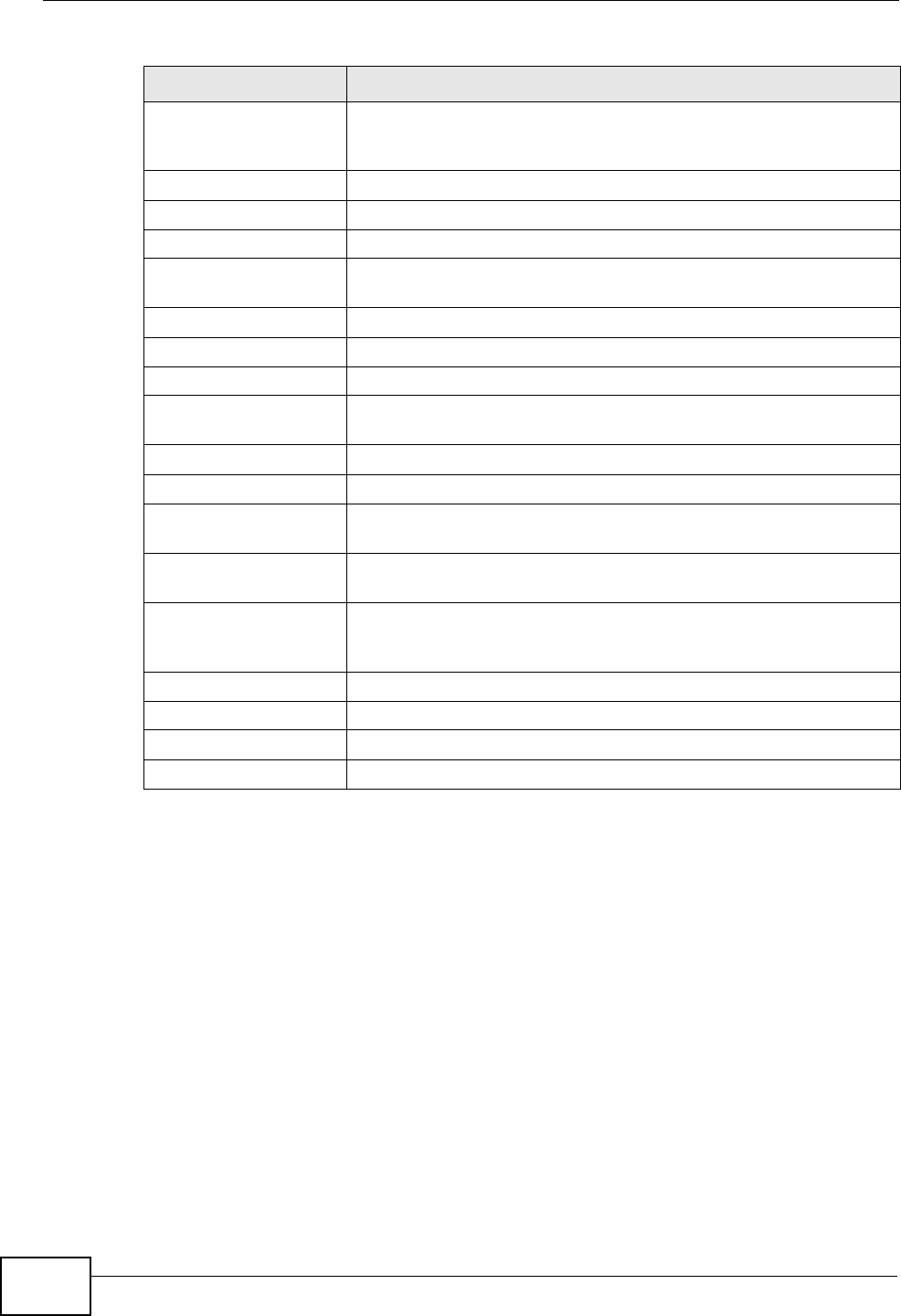
Chapter 28 Product Specifications
P-2612HNU(L)-FxF User’s Guide
302
Wall-mounting Instructions
Do the following to hang your ZyXEL Device on a wall.
Note: See Table 83 on page 295 for the size of screws to use and how far apart to
place them.
1Locate a high position on a wall that is free of obstructions. Use a sturdy wall.
2Drill two holes for the screws. Make sure the distance between the centers of the
holes matches what is listed in the product specifications appendix.
Be careful to avoid damaging pipes or cables located inside the
wall when drilling holes for the screws.
IEEE 802.11 Also known by the brand Wi-Fi, denotes a set of Wireless LAN/
WLAN standards developed by working group 11 of the IEEE
LAN/MAN Standards Committee (IEEE 802)
IEEE 802.11b Uses the 2.4 gigahertz (GHz) band
IEEE 802.11g Uses the 2.4 gigahertz (GHz) band
IEEE 802.11n Uses the 2.4 gigahertz (GHz) band and 5 gigahertz (GHz) band
IEEE 802.11d Standard for Local and Metropolitan Area Networks: Media
Access Control (MAC) Bridges
802.1x Port Based Network Access Control
IEEE 802.11e QoS IEEE 802.11 e Wireless LAN for Quality of Service
ANSI T1.413, Issue 2 Asymmetric Digital Subscriber Line (ADSL) standard
G dmt(G.992.1) G.992.1 Asymmetrical Digital Subscriber Line (ADSL)
Transceivers
ITU G.992.1 (G.DMT) ITU standard for ADSL using discrete multitone modulation
ITU G.992.2 (G. Lite) ITU standard for ADSL using discrete multitone modulation
ITU G.992.3
(G.dmt.bis)
ITU standard (also referred to as ADSL2) that extends the
capability of basic ADSL in data rates
ITU G.992.4
(G.lite.bis)
ITU standard (also referred to as ADSL2) that extends the
capability of basic ADSL in data rates
ITU G.992.5 (ADSL2+) ITU standard (also referred to as ADSL2+) that extends the
capability of basic ADSL by doubling the number of downstream
bits
RFC 2383 ST2+ over ATM Protocol Specification - UNI 3.1 Version
TR-069 TR-069 DSL Forum Standard for CPE Wan Management
TR-064 DSL Forum LAN-Side DSL CPE Configuration
1.363.5 Compliant AAL5 SAR (Segmentation And Re-assembly)
Table 87 Standards Supported (continued)
STANDARD DESCRIPTION
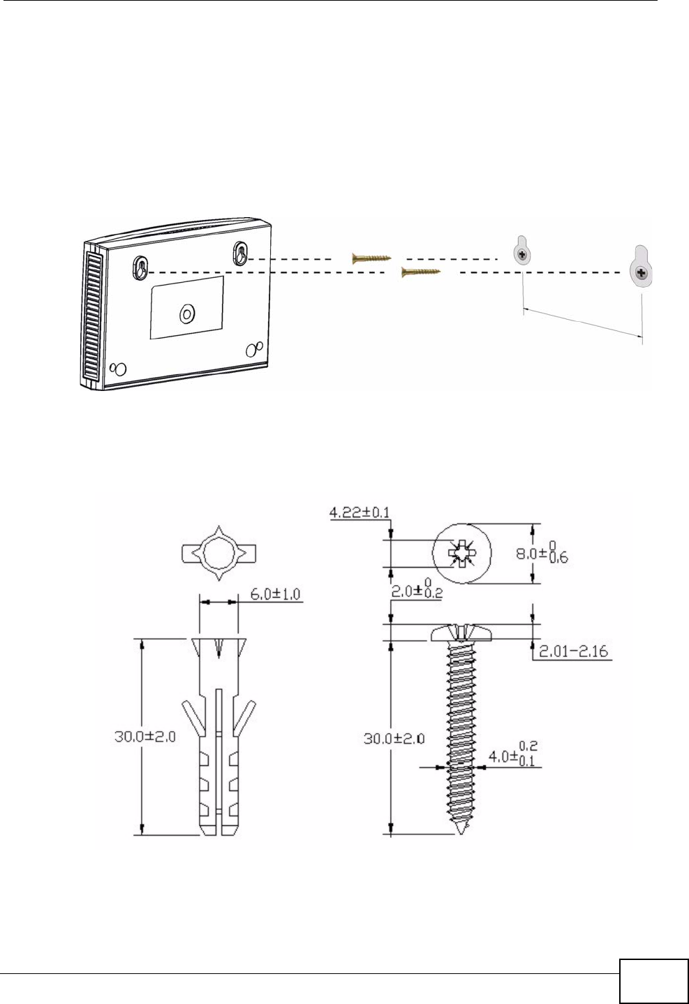
Chapter 28 Product Specifications
P-2612HNU(L)-FxF User’s Guide 303
3Do not screw the screws all the way into the wall. Leave a small gap of about 0.5
cm between the heads of the screws and the wall.
4Make sure the screws are snugly fastened to the wall. They need to hold the
weight of the ZyXEL Device with the connection cables.
5Align the holes on the back of the ZyXEL Device with the screws on the wall. Hang
the ZyXEL Device on the screws.
Figure 130 Wall-mounting Example
The following are dimensions of an M4 tap screw and masonry plug used for wall
mounting. All measurements are in millimeters (mm).
Figure 131 Masonry Plug and M4 Tap Screw

Chapter 28 Product Specifications
P-2612HNU(L)-FxF User’s Guide
304

P-2612HNU(L)-FxF User’s Guide 305
APPENDIX A
IP Addresses and Subnetting
This appendix introduces IP addresses and subnet masks.
IP addresses identify individual devices on a network. Every networking device
(such as computers, servers, routers, and printers) needs an IP address to
communicate across the network. These networking devices are also known as
hosts.
Subnet masks determine the maximum number of possible hosts on a network.
You can also use subnet masks to divide one network into multiple sub-networks.
Introduction to IP Addresses
One part of the IP address is the network number, and the other part is the host
ID. In the same way that houses on a street share a common street name, the
hosts on a network share a common network number. Similarly, as each house
has its own house number, each host on the network has its own unique
identifying number - the host ID. Routers use the network number to send packets
to the correct network, while the host ID determines to which host on the network
the packets are delivered.
Structure
An IP address is made up of four parts, written in dotted decimal notation (for
example, 192.168.1.1). Each of these four parts is known as an octet. An octet is
an eight-digit binary number (for example 11000000, which is 192 in decimal
notation).
Therefore, each octet has a possible range of 00000000 to 11111111 in binary, or
0 to 255 in decimal.
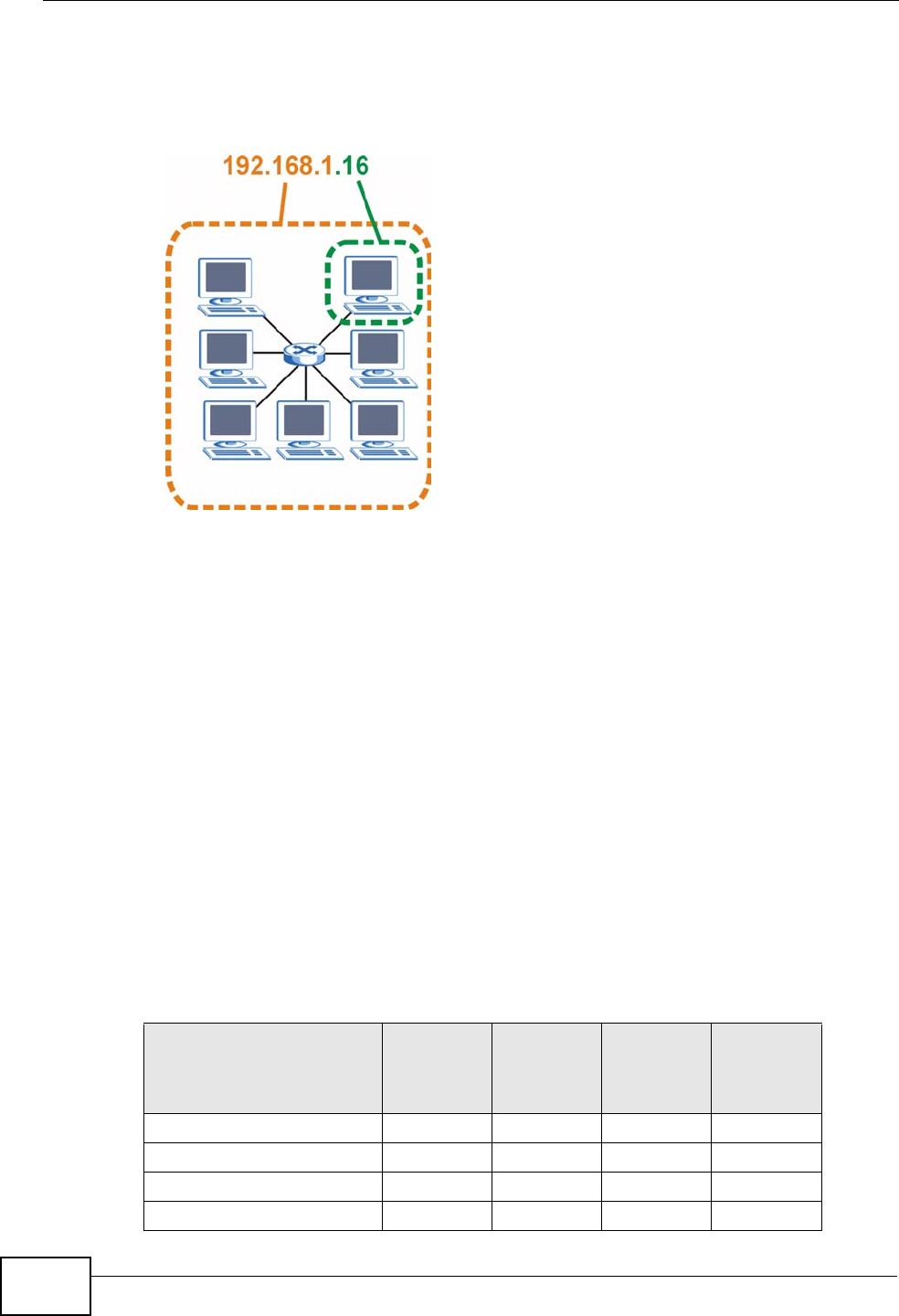
Appendix A IP Addresses and Subnetting
P-2612HNU(L)-FxF User’s Guide
306
The following figure shows an example IP address in which the first three octets
(192.168.1) are the network number, and the fourth octet (16) is the host ID.
Figure 132 Network Number and Host ID
How much of the IP address is the network number and how much is the host ID
varies according to the subnet mask.
Subnet Masks
A subnet mask is used to determine which bits are part of the network number,
and which bits are part of the host ID (using a logical AND operation). The term
“subnet” is short for “sub-network”.
A subnet mask has 32 bits. If a bit in the subnet mask is a “1” then the
corresponding bit in the IP address is part of the network number. If a bit in the
subnet mask is “0” then the corresponding bit in the IP address is part of the host
ID.
The following example shows a subnet mask identifying the network number (in
bold text) and host ID of an IP address (192.168.1.2 in decimal).
Table 88 IP Address Network Number and Host ID Example
1ST
OCTET:
(192)
2ND
OCTET:
(168)
3RD
OCTET:
(1)
4TH
OCTET
(2)
IP Address (Binary) 11000000 10101000 00000001 00000010
Subnet Mask (Binary) 11111111 11111111 11111111 00000000
Network Number 11000000 10101000 00000001
Host ID 00000010
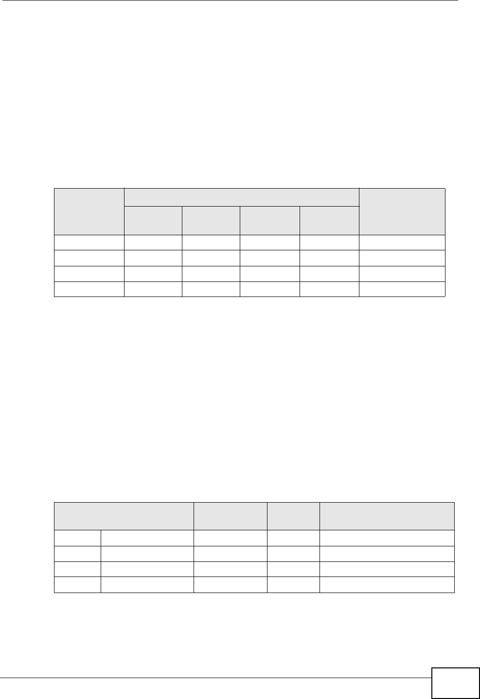
Appendix A IP Addresses and Subnetting
P-2612HNU(L)-FxF User’s Guide 307
By convention, subnet masks always consist of a continuous sequence of ones
beginning from the leftmost bit of the mask, followed by a continuous sequence of
zeros, for a total number of 32 bits.
Subnet masks can be referred to by the size of the network number part (the bits
with a “1” value). For example, an “8-bit mask” means that the first 8 bits of the
mask are ones and the remaining 24 bits are zeroes.
Subnet masks are expressed in dotted decimal notation just like IP addresses. The
following examples show the binary and decimal notation for 8-bit, 16-bit, 24-bit
and 29-bit subnet masks.
Network Size
The size of the network number determines the maximum number of possible
hosts you can have on your network. The larger the number of network number
bits, the smaller the number of remaining host ID bits.
An IP address with host IDs of all zeros is the IP address of the network
(192.168.1.0 with a 24-bit subnet mask, for example). An IP address with host
IDs of all ones is the broadcast address for that network (192.168.1.255 with a
24-bit subnet mask, for example).
As these two IP addresses cannot be used for individual hosts, calculate the
maximum number of possible hosts in a network as follows:
Table 89 Subnet Masks
BINARY
DECIMAL
1ST
OCTET
2ND
OCTET
3RD
OCTET
4TH
OCTET
8-bit mask 11111111 00000000 00000000 00000000 255.0.0.0
16-bit mask 11111111 11111111 00000000 00000000 255.255.0.0
24-bit mask 11111111 11111111 11111111 00000000 255.255.255.0
29-bit mask 11111111 11111111 11111111 11111000 255.255.255.248
Table 90 Maximum Host Numbers
SUBNET MASK HOST ID SIZE MAXIMUM NUMBER OF
HOSTS
8 bits 255.0.0.0 24 bits 224 – 2 16777214
16 bits 255.255.0.0 16 bits 216 – 2 65534
24 bits 255.255.255.0 8 bits 28 – 2 254
29 bits 255.255.255.248 3 bits 23 – 2 6
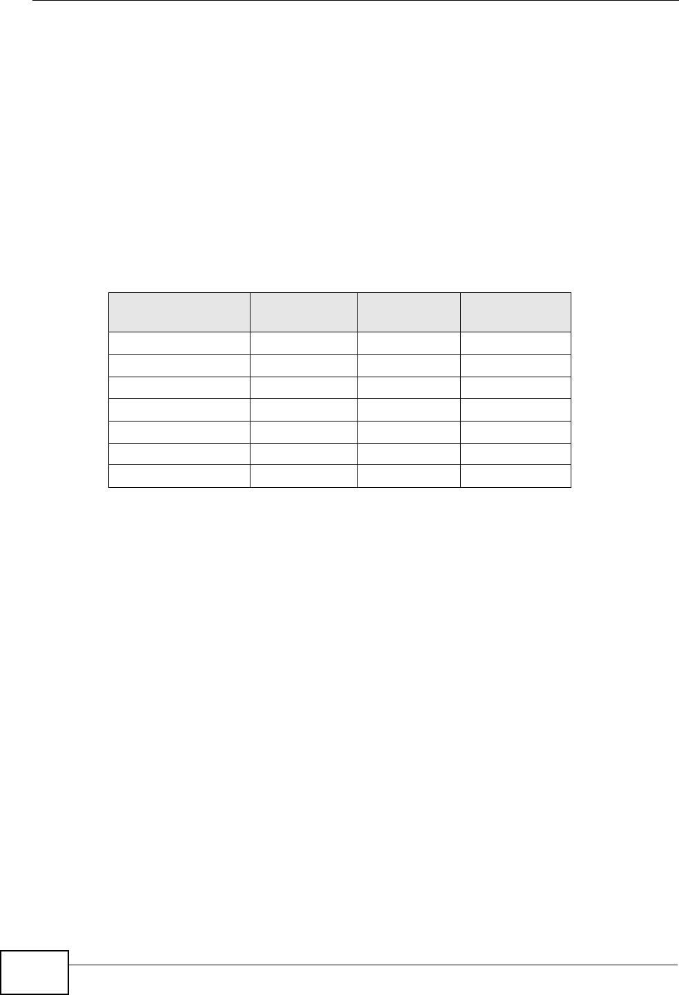
Appendix A IP Addresses and Subnetting
P-2612HNU(L)-FxF User’s Guide
308
Notation
Since the mask is always a continuous number of ones beginning from the left,
followed by a continuous number of zeros for the remainder of the 32 bit mask,
you can simply specify the number of ones instead of writing the value of each
octet. This is usually specified by writing a “/” followed by the number of bits in
the mask after the address.
For example, 192.1.1.0 /25 is equivalent to saying 192.1.1.0 with subnet mask
255.255.255.128.
The following table shows some possible subnet masks using both notations.
Subnetting
You can use subnetting to divide one network into multiple sub-networks. In the
following example a network administrator creates two sub-networks to isolate a
group of servers from the rest of the company network for security reasons.
In this example, the company network address is 192.168.1.0. The first three
octets of the address (192.168.1) are the network number, and the remaining
octet is the host ID, allowing a maximum of 28 – 2 or 254 possible hosts.
Table 91 Alternative Subnet Mask Notation
SUBNET MASK ALTERNATIVE
NOTATION
LAST OCTET
(BINARY)
LAST OCTET
(DECIMAL)
255.255.255.0 /24 0000 0000 0
255.255.255.128 /25 1000 0000 128
255.255.255.192 /26 1100 0000 192
255.255.255.224 /27 1110 0000 224
255.255.255.240 /28 1111 0000 240
255.255.255.248 /29 1111 1000 248
255.255.255.252 /30 1111 1100 252
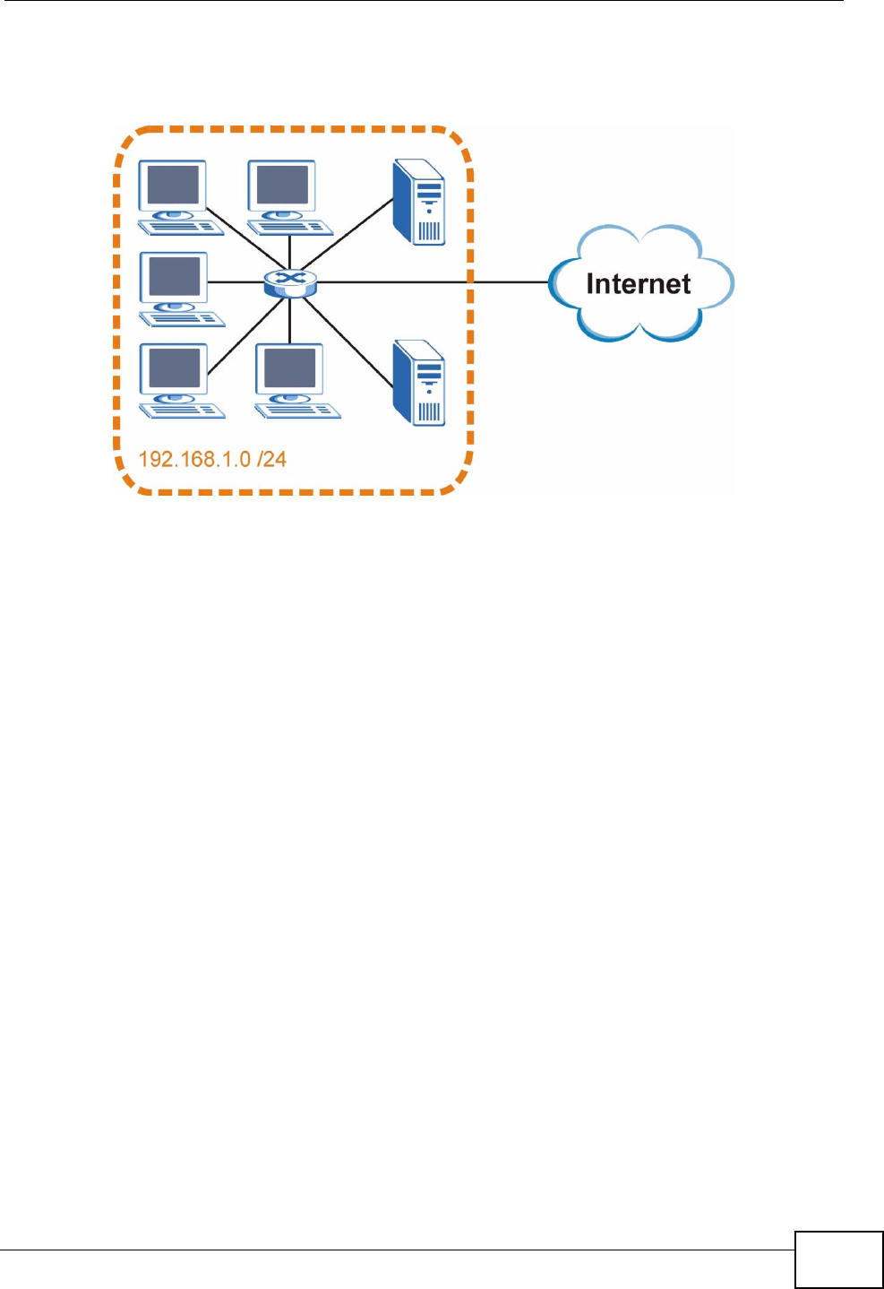
Appendix A IP Addresses and Subnetting
P-2612HNU(L)-FxF User’s Guide 309
The following figure shows the company network before subnetting.
Figure 133 Subnetting Example: Before Subnetting
You can “borrow” one of the host ID bits to divide the network 192.168.1.0 into
two separate sub-networks. The subnet mask is now 25 bits (255.255.255.128 or
/25).
The “borrowed” host ID bit can have a value of either 0 or 1, allowing two
subnets; 192.168.1.0 /25 and 192.168.1.128 /25.
Appendix A IP Addresses and Subnetting
P-2612HNU(L)-FxF User’s Guide
310
The following figure shows the company network after subnetting. There are now
two sub-networks, A and B.
Figure 134 Subnetting Example: After Subnetting
In a 25-bit subnet the host ID has 7 bits, so each sub-network has a maximum of
27– 2 or 126 possible hosts (a host ID of all zeroes is the subnet’s address itself,
all ones is the subnet’s broadcast address).
192.168.1.0 with mask 255.255.255.128 is subnet A itself, and 192.168.1.127
with mask 255.255.255.128 is its broadcast address. Therefore, the lowest IP
address that can be assigned to an actual host for subnet A is 192.168.1.1 and
the highest is 192.168.1.126.
Similarly, the host ID range for subnet B is 192.168.1.129 to 192.168.1.254.
Example: Four Subnets
The previous example illustrated using a 25-bit subnet mask to divide a 24-bit
address into two subnets. Similarly, to divide a 24-bit address into four subnets,
you need to “borrow” two host ID bits to give four possible combinations (00, 01,
10 and 11). The subnet mask is 26 bits
(11111111.11111111.11111111.11000000) or 255.255.255.192.
Appendix A IP Addresses and Subnetting
P-2612HNU(L)-FxF User’s Guide 311
Each subnet contains 6 host ID bits, giving 26- 2 or 62 hosts for each subnet (a
host ID of all zeroes is the subnet itself, all ones is the subnet’s broadcast
address).
Table 92 Subnet 1
IP/SUBNET MASK NETWORK NUMBER LAST OCTET BIT
VALUE
IP Address (Decimal) 192.168.1. 0
IP Address (Binary) 11000000.10101000.00000001. 00000000
Subnet Mask (Binary) 11111111.11111111.11111111. 11000000
Subnet Address:
192.168.1.0
Lowest Host ID: 192.168.1.1
Broadcast Address:
192.168.1.63
Highest Host ID: 192.168.1.62
Table 93 Subnet 2
IP/SUBNET MASK NETWORK NUMBER LAST OCTET BIT
VALUE
IP Address 192.168.1. 64
IP Address (Binary) 11000000.10101000.00000001. 01000000
Subnet Mask (Binary) 11111111.11111111.11111111. 11000000
Subnet Address:
192.168.1.64
Lowest Host ID: 192.168.1.65
Broadcast Address:
192.168.1.127
Highest Host ID: 192.168.1.126
Table 94 Subnet 3
IP/SUBNET MASK NETWORK NUMBER LAST OCTET BIT
VALUE
IP Address 192.168.1. 128
IP Address (Binary) 11000000.10101000.00000001. 10000000
Subnet Mask (Binary) 11111111.11111111.11111111. 11000000
Subnet Address:
192.168.1.128
Lowest Host ID: 192.168.1.129
Broadcast Address:
192.168.1.191
Highest Host ID: 192.168.1.190
Table 95 Subnet 4
IP/SUBNET MASK NETWORK NUMBER LAST OCTET BIT
VALUE
IP Address 192.168.1. 192
IP Address (Binary) 11000000.10101000.00000001. 11000000
Subnet Mask (Binary) 11111111.11111111.11111111. 11000000
Subnet Address:
192.168.1.192
Lowest Host ID: 192.168.1.193
Broadcast Address:
192.168.1.255
Highest Host ID: 192.168.1.254
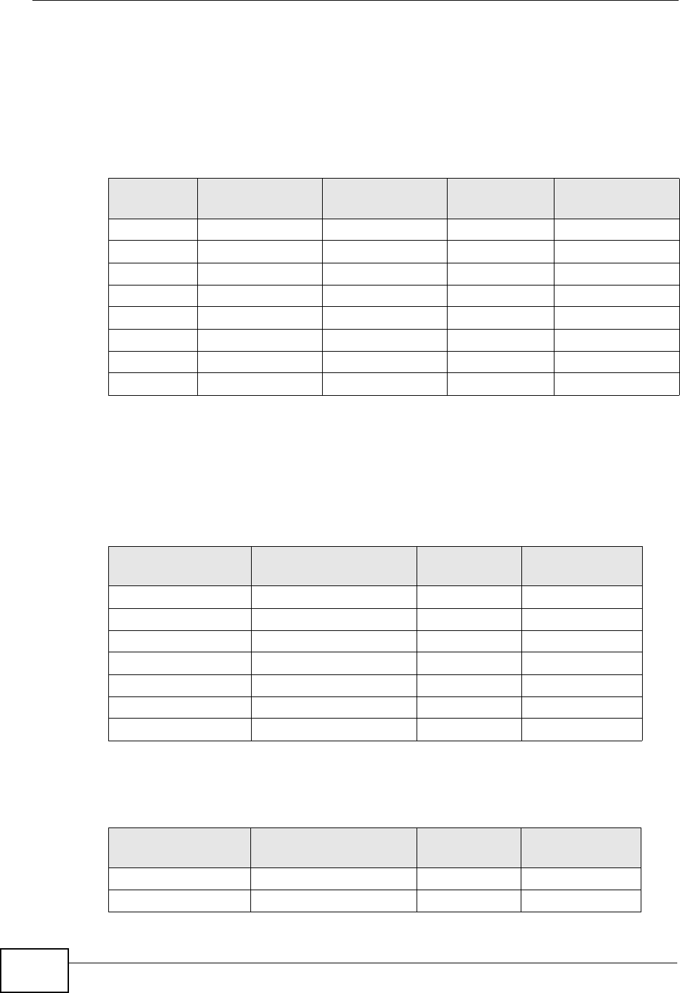
Appendix A IP Addresses and Subnetting
P-2612HNU(L)-FxF User’s Guide
312
Example: Eight Subnets
Similarly, use a 27-bit mask to create eight subnets (000, 001, 010, 011, 100,
101, 110 and 111).
The following table shows IP address last octet values for each subnet.
Subnet Planning
The following table is a summary for subnet planning on a network with a 24-bit
network number.
The following table is a summary for subnet planning on a network with a 16-bit
network number.
Table 96 Eight Subnets
SUBNET SUBNET
ADDRESS FIRST ADDRESS LAST
ADDRESS
BROADCAST
ADDRESS
1 0 1 30 31
2 32 33 62 63
3 64 65 94 95
4 96 97 126 127
5 128 129 158 159
6 160 161 190 191
7 192 193 222 223
8 224 225 254 255
Table 97 24-bit Network Number Subnet Planning
NO. “BORROWED”
HOST BITS SUBNET MASK NO. SUBNETS NO. HOSTS PER
SUBNET
1 255.255.255.128 (/25) 2 126
2 255.255.255.192 (/26) 4 62
3 255.255.255.224 (/27) 8 30
4 255.255.255.240 (/28) 16 14
5 255.255.255.248 (/29) 32 6
6 255.255.255.252 (/30) 64 2
7 255.255.255.254 (/31) 128 1
Table 98 16-bit Network Number Subnet Planning
NO. “BORROWED”
HOST BITS SUBNET MASK NO. SUBNETS NO. HOSTS PER
SUBNET
1 255.255.128.0 (/17) 2 32766
2 255.255.192.0 (/18) 4 16382
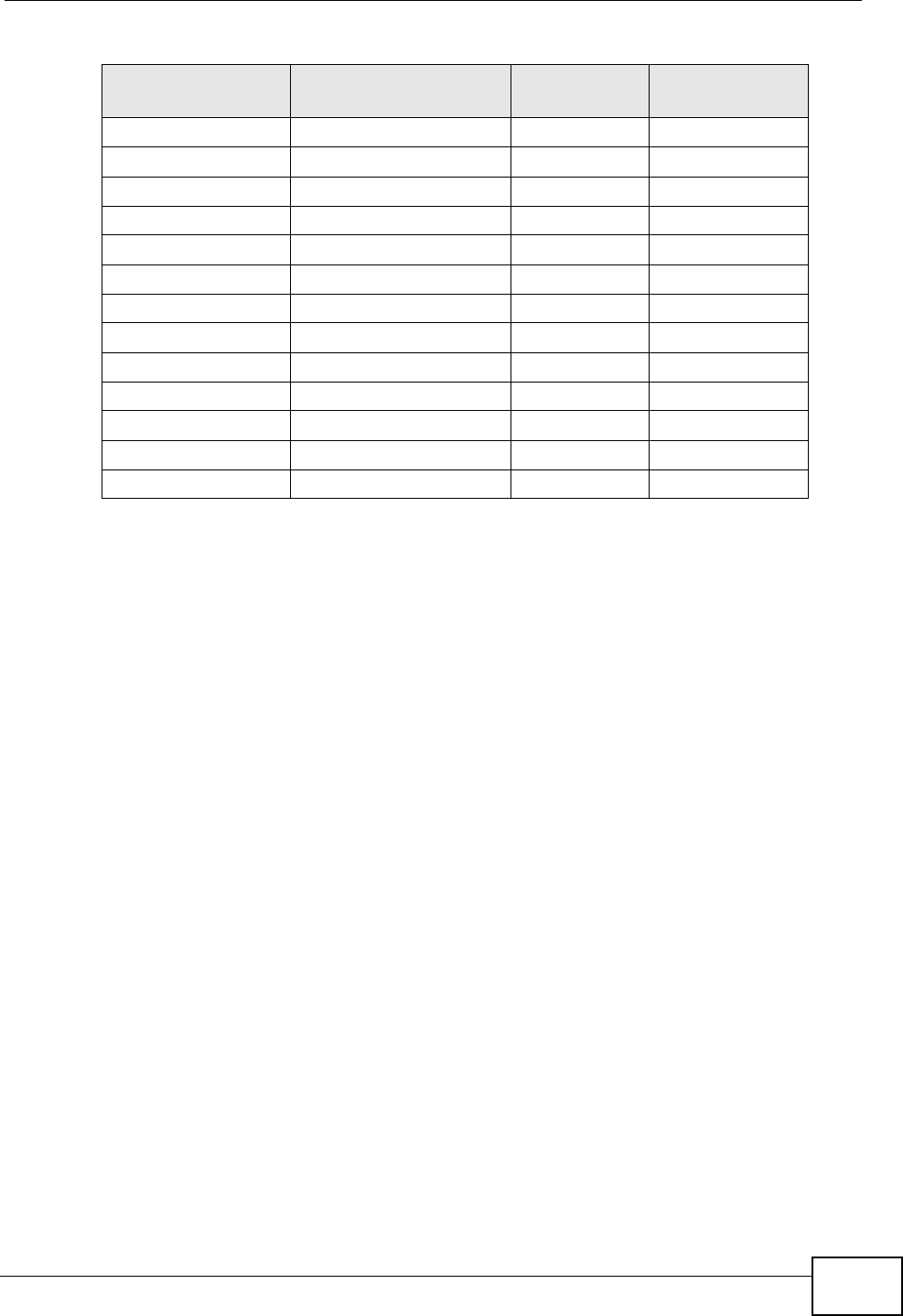
Appendix A IP Addresses and Subnetting
P-2612HNU(L)-FxF User’s Guide 313
Configuring IP Addresses
Where you obtain your network number depends on your particular situation. If
the ISP or your network administrator assigns you a block of registered IP
addresses, follow their instructions in selecting the IP addresses and the subnet
mask.
If the ISP did not explicitly give you an IP network number, then most likely you
have a single user account and the ISP will assign you a dynamic IP address when
the connection is established. If this is the case, it is recommended that you select
a network number from 192.168.0.0 to 192.168.255.0. The Internet Assigned
Number Authority (IANA) reserved this block of addresses specifically for private
use; please do not use any other number unless you are told otherwise. You must
also enable Network Address Translation (NAT) on the ZyXEL Device.
Once you have decided on the network number, pick an IP address for your ZyXEL
Device that is easy to remember (for instance, 192.168.1.1) but make sure that
no other device on your network is using that IP address.
The subnet mask specifies the network number portion of an IP address. Your
ZyXEL Device will compute the subnet mask automatically based on the IP
address that you entered. You don't need to change the subnet mask computed by
the ZyXEL Device unless you are instructed to do otherwise.
3 255.255.224.0 (/19) 8 8190
4 255.255.240.0 (/20) 16 4094
5 255.255.248.0 (/21) 32 2046
6 255.255.252.0 (/22) 64 1022
7 255.255.254.0 (/23) 128 510
8 255.255.255.0 (/24) 256 254
9 255.255.255.128 (/25) 512 126
10 255.255.255.192 (/26) 1024 62
11 255.255.255.224 (/27) 2048 30
12 255.255.255.240 (/28) 4096 14
13 255.255.255.248 (/29) 8192 6
14 255.255.255.252 (/30) 16384 2
15 255.255.255.254 (/31) 32768 1
Table 98 16-bit Network Number Subnet Planning (continued)
NO. “BORROWED”
HOST BITS SUBNET MASK NO. SUBNETS NO. HOSTS PER
SUBNET

Appendix A IP Addresses and Subnetting
P-2612HNU(L)-FxF User’s Guide
314
Private IP Addresses
Every machine on the Internet must have a unique address. If your networks are
isolated from the Internet (running only between two branch offices, for example)
you can assign any IP addresses to the hosts without problems. However, the
Internet Assigned Numbers Authority (IANA) has reserved the following three
blocks of IP addresses specifically for private networks:
• 10.0.0.0 — 10.255.255.255
• 172.16.0.0 — 172.31.255.255
• 192.168.0.0 — 192.168.255.255
You can obtain your IP address from the IANA, from an ISP, or it can be assigned
from a private network. If you belong to a small organization and your Internet
access is through an ISP, the ISP can provide you with the Internet addresses for
your local networks. On the other hand, if you are part of a much larger
organization, you should consult your network administrator for the appropriate IP
addresses.
Regardless of your particular situation, do not create an arbitrary IP address;
always follow the guidelines above. For more information on address assignment,
please refer to RFC 1597, Address Allocation for Private Internets and RFC 1466,
Guidelines for Management of IP Address Space.
IP Address Conflicts
Each device on a network must have a unique IP address. Devices with duplicate
IP addresses on the same network will not be able to access the Internet or other
resources. The devices may also be unreachable through the network.
Conflicting Computer IP Addresses Example
More than one device can not use the same IP address. In the following example
computer A has a static (or fixed) IP address that is the same as the IP address
that a DHCP server assigns to computer B which is a DHCP client. Neither can
access the Internet. This problem can be solved by assigning a different static IP
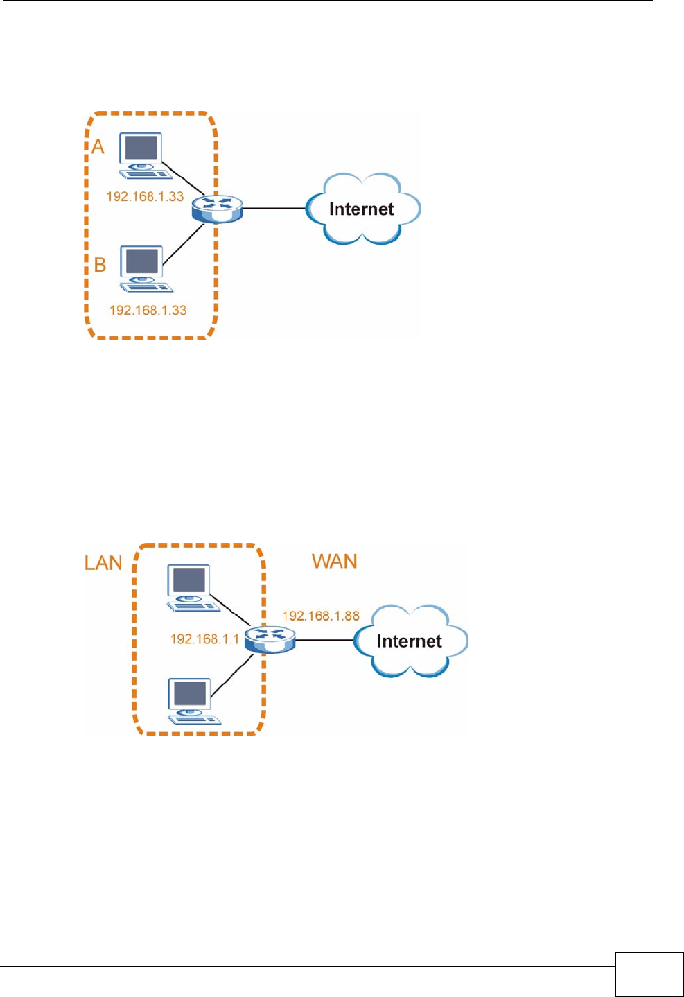
Appendix A IP Addresses and Subnetting
P-2612HNU(L)-FxF User’s Guide 315
address to computer A or setting computer A to obtain an IP address
automatically.
Figure 135 Conflicting Computer IP Addresses Example
Conflicting Router IP Addresses Example
Since a router connects different networks, it must have interfaces using different
network numbers. For example, if a router is set between a LAN and the Internet
(WAN), the router’s LAN and WAN addresses must be on different subnets. In the
following example, the LAN and WAN are on the same subnet. The LAN computers
cannot access the Internet because the router cannot route between networks.
Figure 136 Conflicting Computer IP Addresses Example
Conflicting Computer and Router IP Addresses Example
More than one device can not use the same IP address. In the following example,
the computer and the router’s LAN port both use 192.168.1.1 as the IP address.
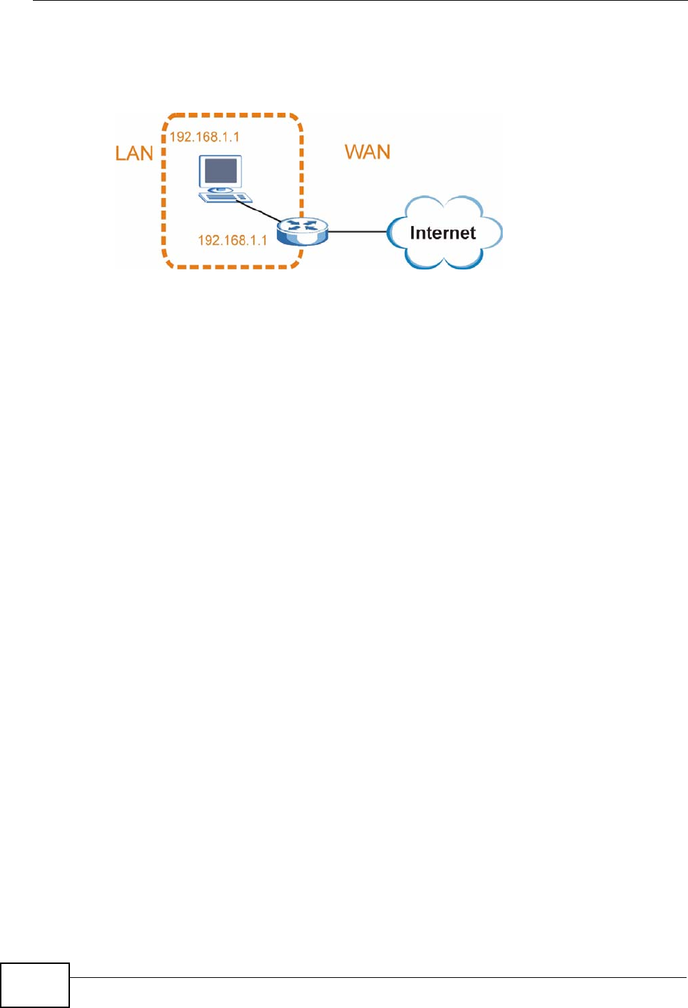
Appendix A IP Addresses and Subnetting
P-2612HNU(L)-FxF User’s Guide
316
The computer cannot access the Internet. This problem can be solved by
assigning a different IP address to the computer or the router’s LAN port.
Figure 137 Conflicting Computer and Router IP Addresses Example

P-2612HNU(L)-FxF User’s Guide 317
APPENDIX B
Setting Up Your Computer’s IP
Address
Note: Your specific ZyXEL Device may not support all of the operating systems
described in this appendix. See the product specifications for more information
about which operating systems are supported.
This appendix shows you how to configure the IP settings on your computer in
order for it to be able to communicate with the other devices on your network.
Windows Vista/XP/2000, Mac OS 9/OS X, and all versions of UNIX/LINUX include
the software components you need to use TCP/IP on your computer.
If you manually assign IP information instead of using a dynamic IP, make sure
that your network’s computers have IP addresses that place them in the same
subnet.
In this appendix, you can set up an IP address for:
•Windows XP/NT/2000 on page 317
•Windows Vista on page 321
•Windows 7 on page 325
•Mac OS X: 10.3 and 10.4 on page 329
•Mac OS X: 10.5 on page 333
•Linux: Ubuntu 8 (GNOME) on page 336
•Linux: openSUSE 10.3 (KDE) on page 341
Windows XP/NT/2000
The following example uses the default Windows XP display theme but can also
apply to Windows 2000 and Windows NT.
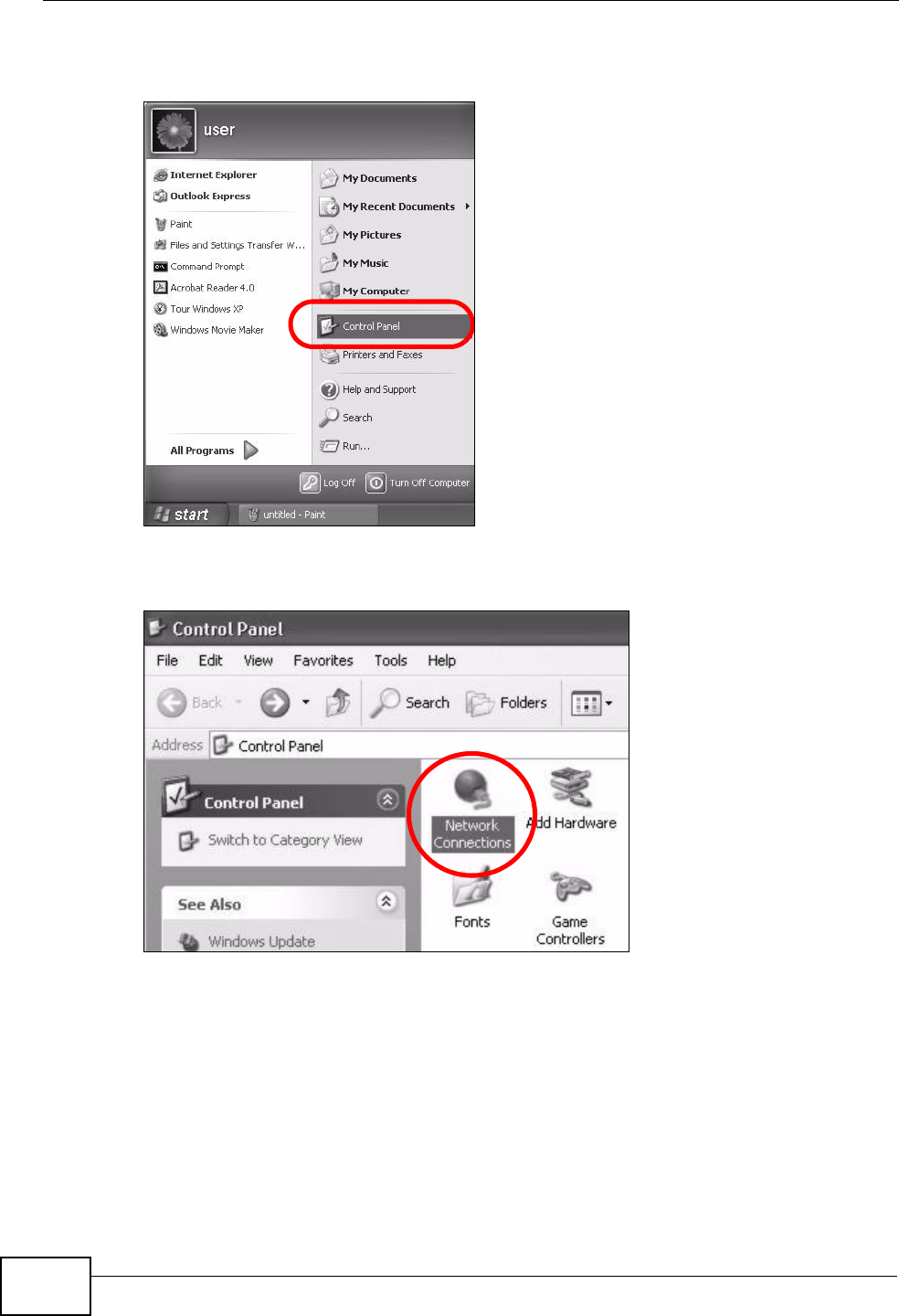
Appendix B Setting Up Your Computer’s IP Address
P-2612HNU(L)-FxF User’s Guide
318
1Click Start > Control Panel.
Figure 138 Windows XP: Start Menu
2In the Control Panel, click the Network Connections icon.
Figure 139 Windows XP: Control Panel
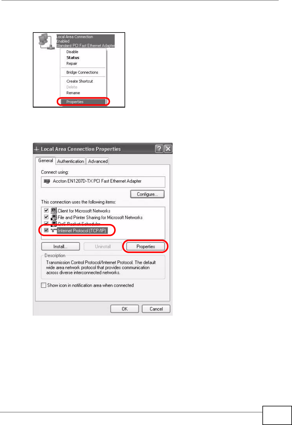
Appendix B Setting Up Your Computer’s IP Address
P-2612HNU(L)-FxF User’s Guide 319
3Right-click Local Area Connection and then select Properties.
Figure 140 Windows XP: Control Panel > Network Connections > Properties
4On the General tab, select Internet Protocol (TCP/IP) and then click
Properties.
Figure 141 Windows XP: Local Area Connection Properties
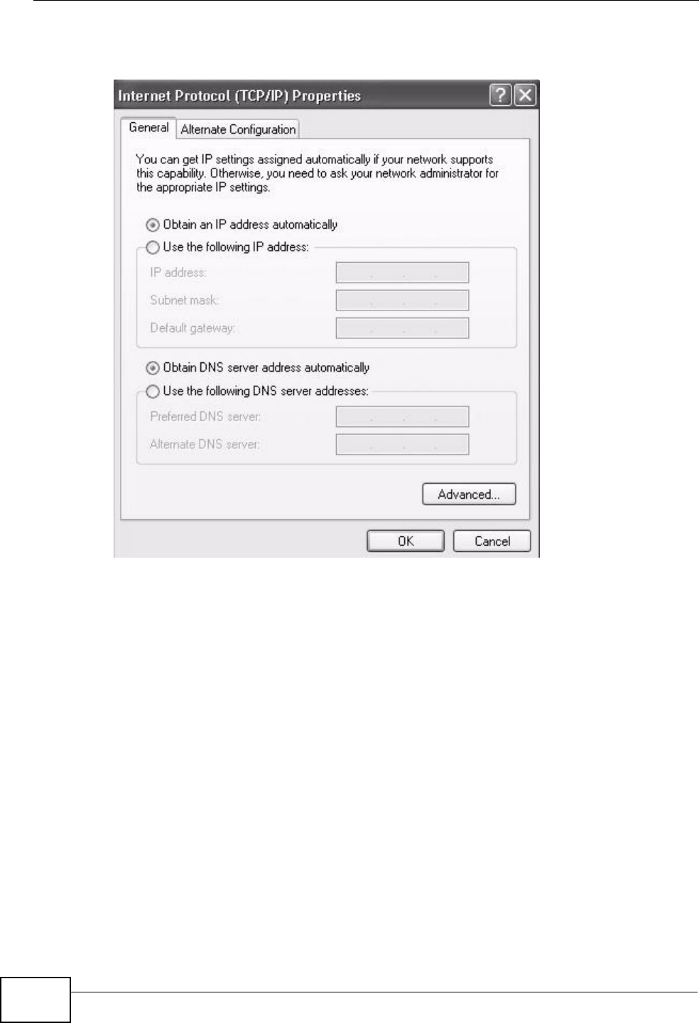
Appendix B Setting Up Your Computer’s IP Address
P-2612HNU(L)-FxF User’s Guide
320
5The Internet Protocol TCP/IP Properties window opens.
Figure 142 Windows XP: Internet Protocol (TCP/IP) Properties
6Select Obtain an IP address automatically if your network administrator or ISP
assigns your IP address dynamically.
Select Use the following IP Address and fill in the IP address, Subnet mask,
and Default gateway fields if you have a static IP address that was assigned to
you by your network administrator or ISP. You may also have to enter a Preferred
DNS server and an Alternate DNS server, if that information was provided.
7Click OK to close the Internet Protocol (TCP/IP) Properties window.
8Click OK to close the Local Area Connection Properties window.
Verifying Settings
1Click Start > All Programs > Accessories > Command Prompt.
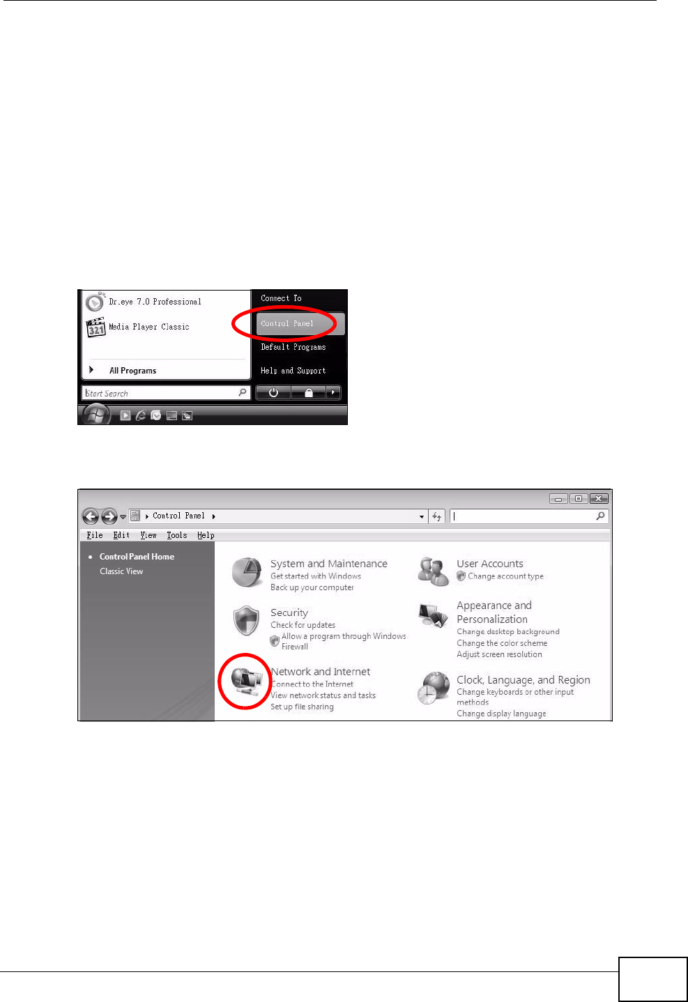
Appendix B Setting Up Your Computer’s IP Address
P-2612HNU(L)-FxF User’s Guide 321
2In the Command Prompt window, type "ipconfig" and then press [ENTER].
You can also go to Start > Control Panel > Network Connections, right-click a
network connection, click Status and then click the Support tab to view your IP
address and connection information.
Windows Vista
This section shows screens from Windows Vista Professional.
1Click Start > Control Panel.
Figure 143 Windows Vista: Start Menu
2In the Control Panel, click the Network and Internet icon.
Figure 144 Windows Vista: Control Panel
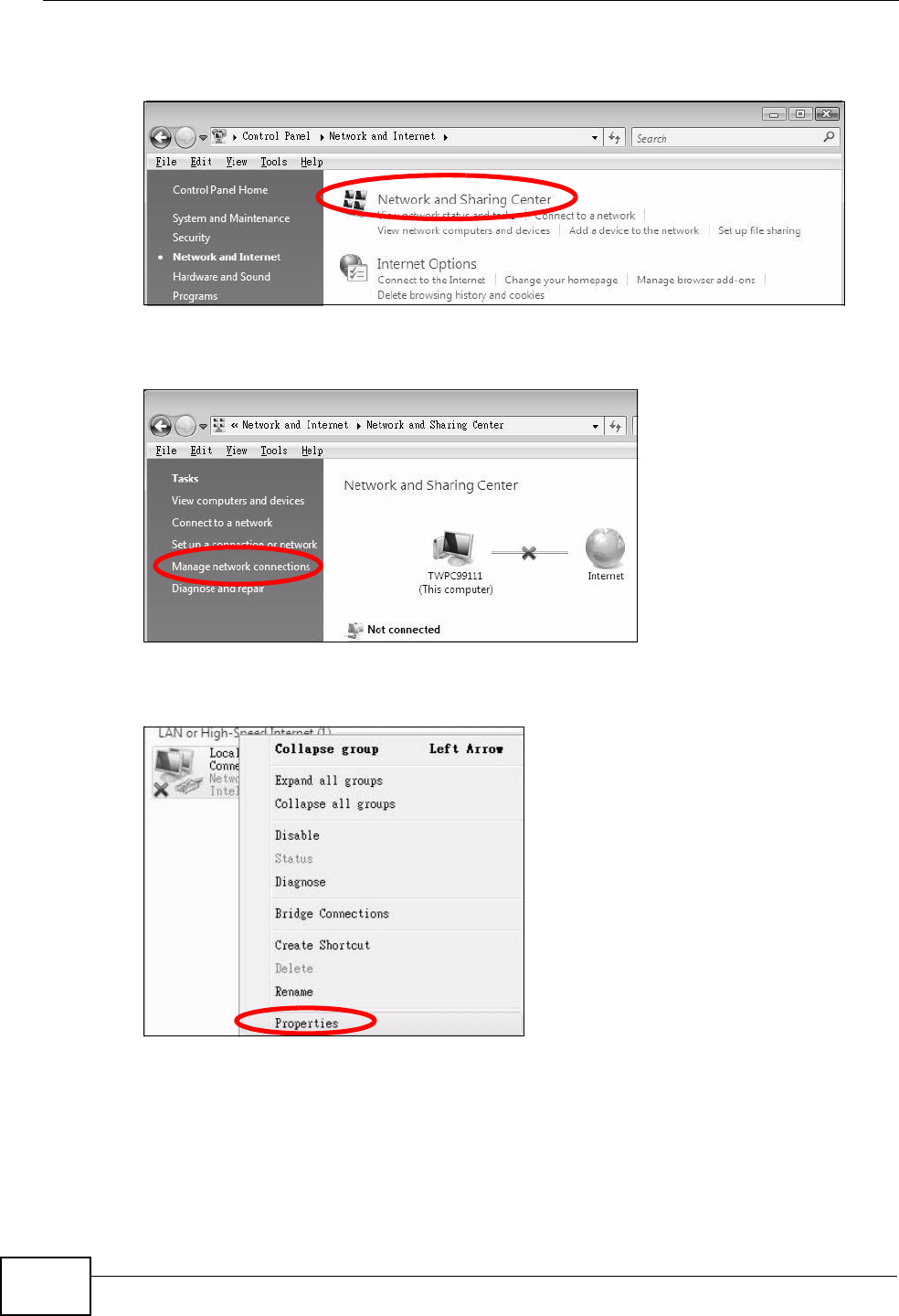
Appendix B Setting Up Your Computer’s IP Address
P-2612HNU(L)-FxF User’s Guide
322
3Click the Network and Sharing Center icon.
Figure 145 Windows Vista: Network And Internet
4Click Manage network connections.
Figure 146 Windows Vista: Network and Sharing Center
5Right-click Local Area Connection and then select Properties.
Figure 147 Windows Vista: Network and Sharing Center
Note: During this procedure, click Continue whenever Windows displays a screen
saying that it needs your permission to continue.
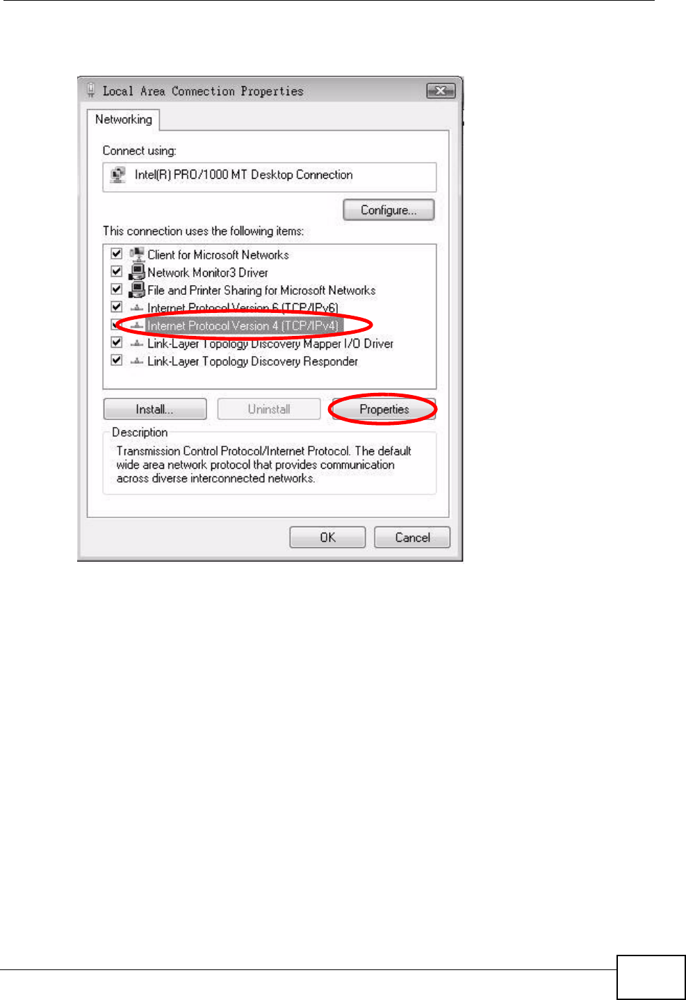
Appendix B Setting Up Your Computer’s IP Address
P-2612HNU(L)-FxF User’s Guide 323
6Select Internet Protocol Version 4 (TCP/IPv4) and then select Properties.
Figure 148 Windows Vista: Local Area Connection Properties
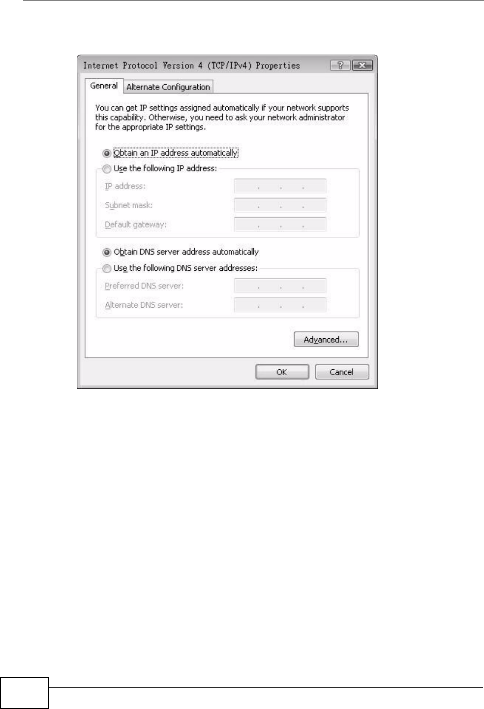
Appendix B Setting Up Your Computer’s IP Address
P-2612HNU(L)-FxF User’s Guide
324
7The Internet Protocol Version 4 (TCP/IPv4) Properties window opens.
Figure 149 Windows Vista: Internet Protocol Version 4 (TCP/IPv4) Properties
8Select Obtain an IP address automatically if your network administrator or ISP
assigns your IP address dynamically.
Select Use the following IP Address and fill in the IP address, Subnet mask,
and Default gateway fields if you have a static IP address that was assigned to
you by your network administrator or ISP. You may also have to enter a Preferred
DNS server and an Alternate DNS server, if that information was
provided.Click Advanced.
9Click OK to close the Internet Protocol (TCP/IP) Properties window.
10 Click OK to close the Local Area Connection Properties window.
Verifying Settings
1Click Start > All Programs > Accessories > Command Prompt.
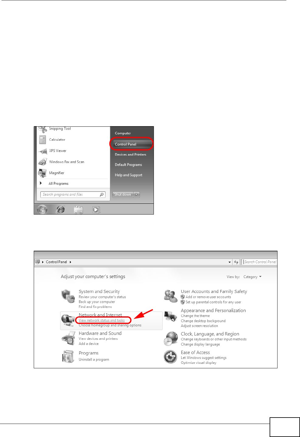
Appendix B Setting Up Your Computer’s IP Address
P-2612HNU(L)-FxF User’s Guide 325
2In the Command Prompt window, type "ipconfig" and then press [ENTER].
You can also go to Start > Control Panel > Network Connections, right-click a
network connection, click Status and then click the Support tab to view your IP
address and connection information.
Windows 7
This section shows screens from Windows 7 Enterprise.
1Click Start > Control Panel.
Figure 150 Windows 7: Start Menu
2In the Control Panel, click View network status and tasks under the
Network and Internet category.
Figure 151 Windows 7: Control Panel
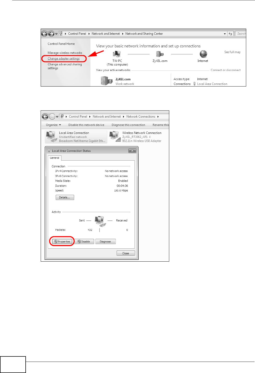
Appendix B Setting Up Your Computer’s IP Address
P-2612HNU(L)-FxF User’s Guide
326
3Click Change adapter settings.
Figure 152 Windows 7: Network And Sharing Center
4Double click Local Area Connection and then select Properties.
Figure 153 Windows 7: Local Area Connection Status
Note: During this procedure, click Continue whenever Windows displays a screen
saying that it needs your permission to continue.
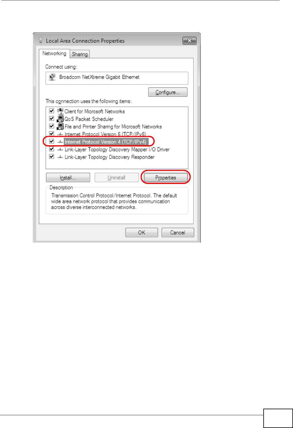
Appendix B Setting Up Your Computer’s IP Address
P-2612HNU(L)-FxF User’s Guide 327
5Select Internet Protocol Version 4 (TCP/IPv4) and then select Properties.
Figure 154 Windows 7: Local Area Connection Properties
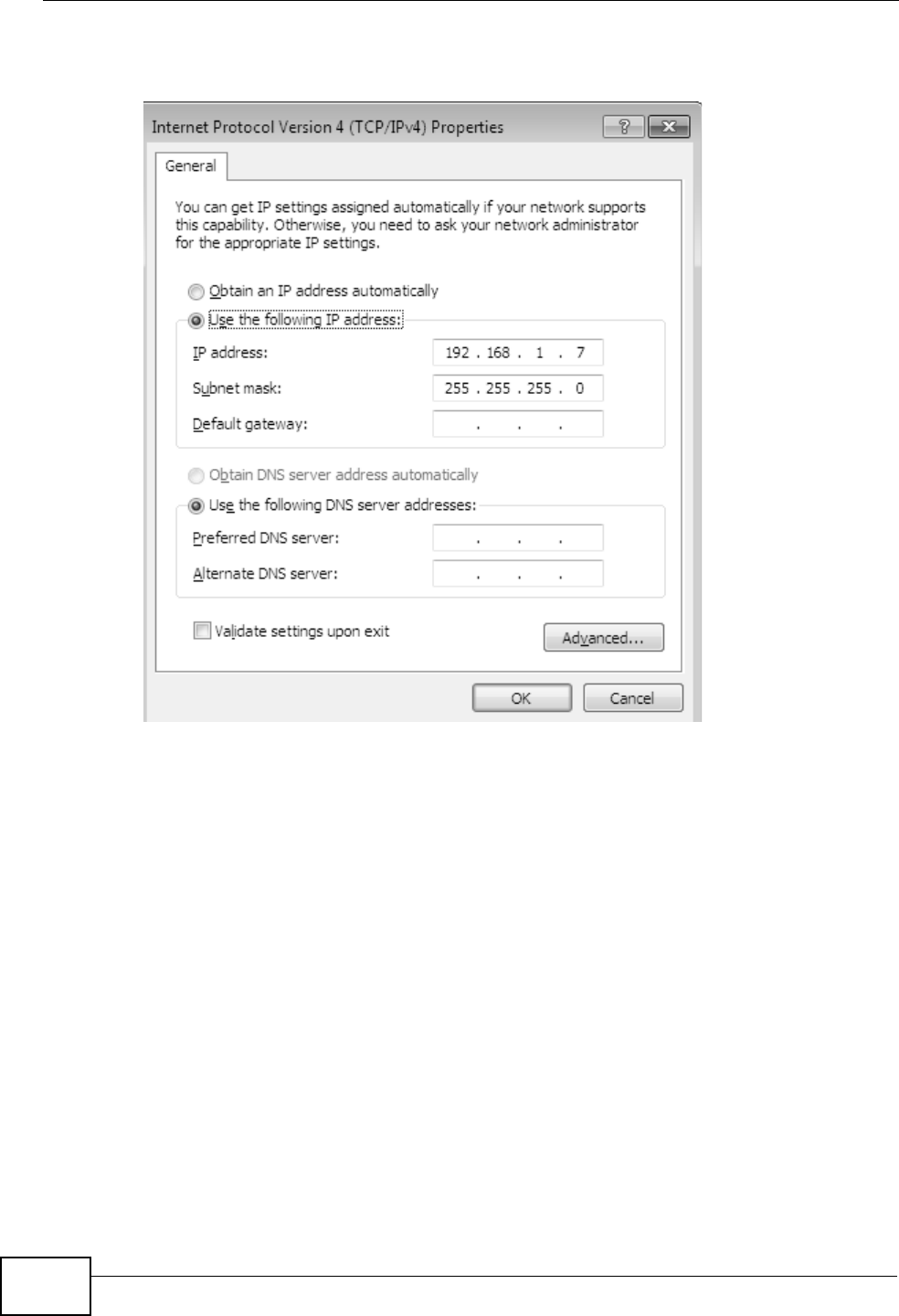
Appendix B Setting Up Your Computer’s IP Address
P-2612HNU(L)-FxF User’s Guide
328
6The Internet Protocol Version 4 (TCP/IPv4) Properties window opens.
Figure 155 Windows 7: Internet Protocol Version 4 (TCP/IPv4) Properties
7Select Obtain an IP address automatically if your network administrator or ISP
assigns your IP address dynamically.
Select Use the following IP Address and fill in the IP address, Subnet mask,
and Default gateway fields if you have a static IP address that was assigned to
you by your network administrator or ISP. You may also have to enter a Preferred
DNS server and an Alternate DNS server, if that information was provided.
Click Advanced if you want to configure advanced settings for IP, DNS and WINS.
8Click OK to close the Internet Protocol (TCP/IP) Properties window.
9Click OK to close the Local Area Connection Properties window.
Verifying Settings
1Click Start > All Programs > Accessories > Command Prompt.
2In the Command Prompt window, type "ipconfig" and then press [ENTER].
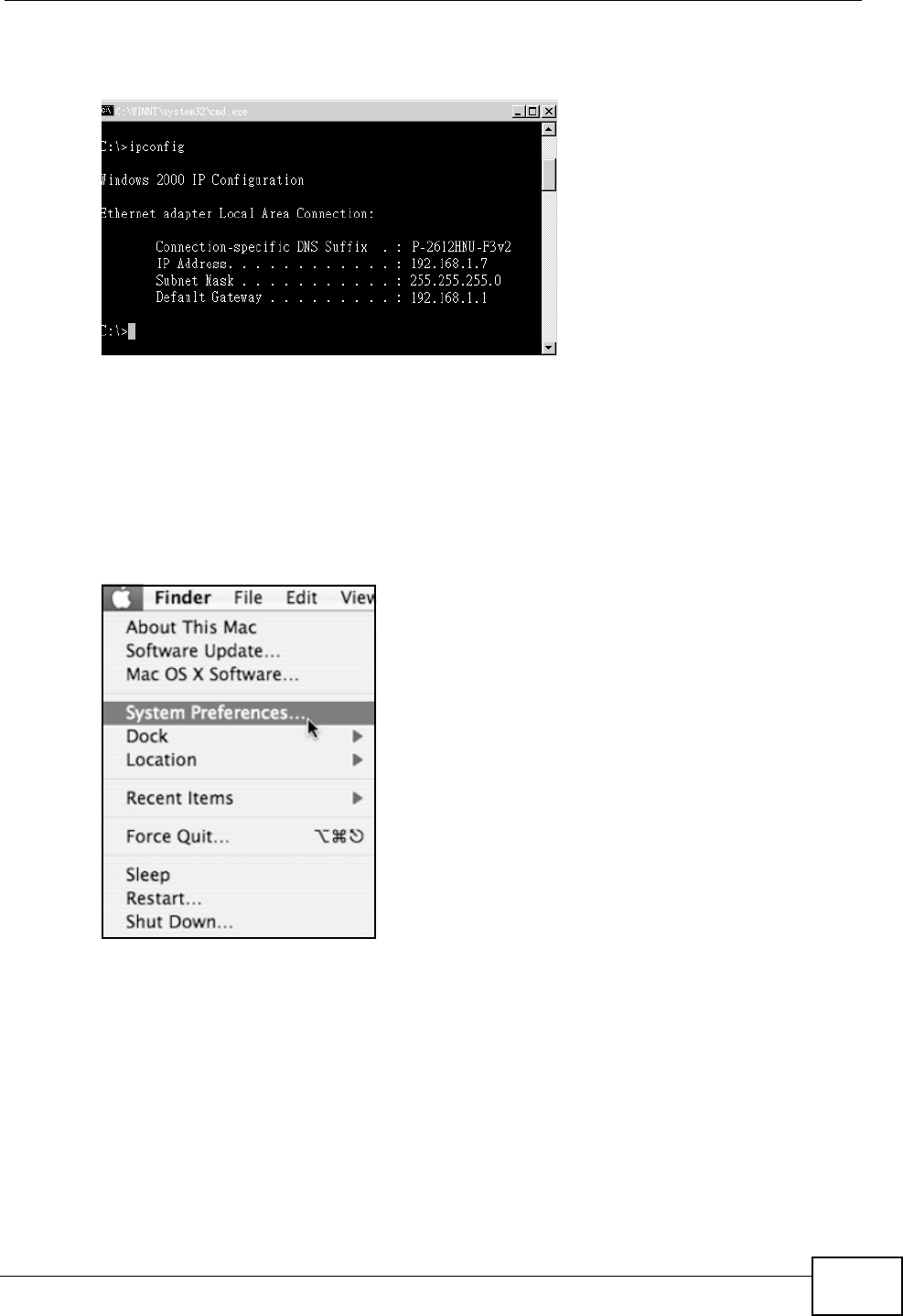
Appendix B Setting Up Your Computer’s IP Address
P-2612HNU(L)-FxF User’s Guide 329
3The IP settings are displayed as follows.
Figure 156 Windows 7: Internet Protocol Version 4 (TCP/IPv4) Properties
Mac OS X: 10.3 and 10.4
The screens in this section are from Mac OS X 10.4 but can also apply to 10.3.
1Click Apple > System Preferences.
Figure 157 Mac OS X 10.4: Apple Menu
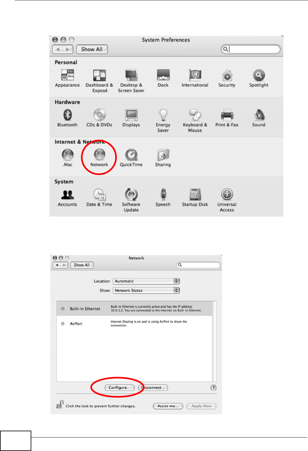
Appendix B Setting Up Your Computer’s IP Address
P-2612HNU(L)-FxF User’s Guide
330
2In the System Preferences window, click the Network icon.
Figure 158 Mac OS X 10.4: System Preferences
3When the Network preferences pane opens, select Built-in Ethernet from the
network connection type list, and then click Configure.
Figure 159 Mac OS X 10.4: Network Preferences

Appendix B Setting Up Your Computer’s IP Address
P-2612HNU(L)-FxF User’s Guide 331
4For dynamically assigned settings, select Using DHCP from the Configure IPv4
list in the TCP/IP tab.
Figure 160 Mac OS X 10.4: Network Preferences > TCP/IP Tab.
5For statically assigned settings, do the following:
• From the Configure IPv4 list, select Manually.
• In the IP Address field, type your IP address.
• In the Subnet Mask field, type your subnet mask.
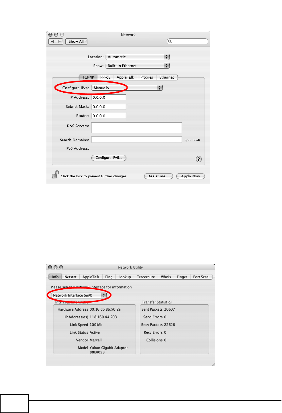
Appendix B Setting Up Your Computer’s IP Address
P-2612HNU(L)-FxF User’s Guide
332
• In the Router field, type the IP address of your device.
Figure 161 Mac OS X 10.4: Network Preferences > Ethernet
6Click Apply Now and close the window.
Verifying Settings
Check your TCP/IP properties by clicking Applications > Utilities > Network
Utilities, and then selecting the appropriate Network Interface from the Info
tab.
Figure 162 Mac OS X 10.4: Network Utility
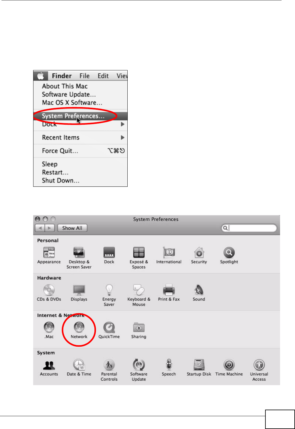
Appendix B Setting Up Your Computer’s IP Address
P-2612HNU(L)-FxF User’s Guide 333
Mac OS X: 10.5
The screens in this section are from Mac OS X 10.5.
1Click Apple > System Preferences.
Figure 163 Mac OS X 10.5: Apple Menu
2In System Preferences, click the Network icon.
Figure 164 Mac OS X 10.5: Systems Preferences
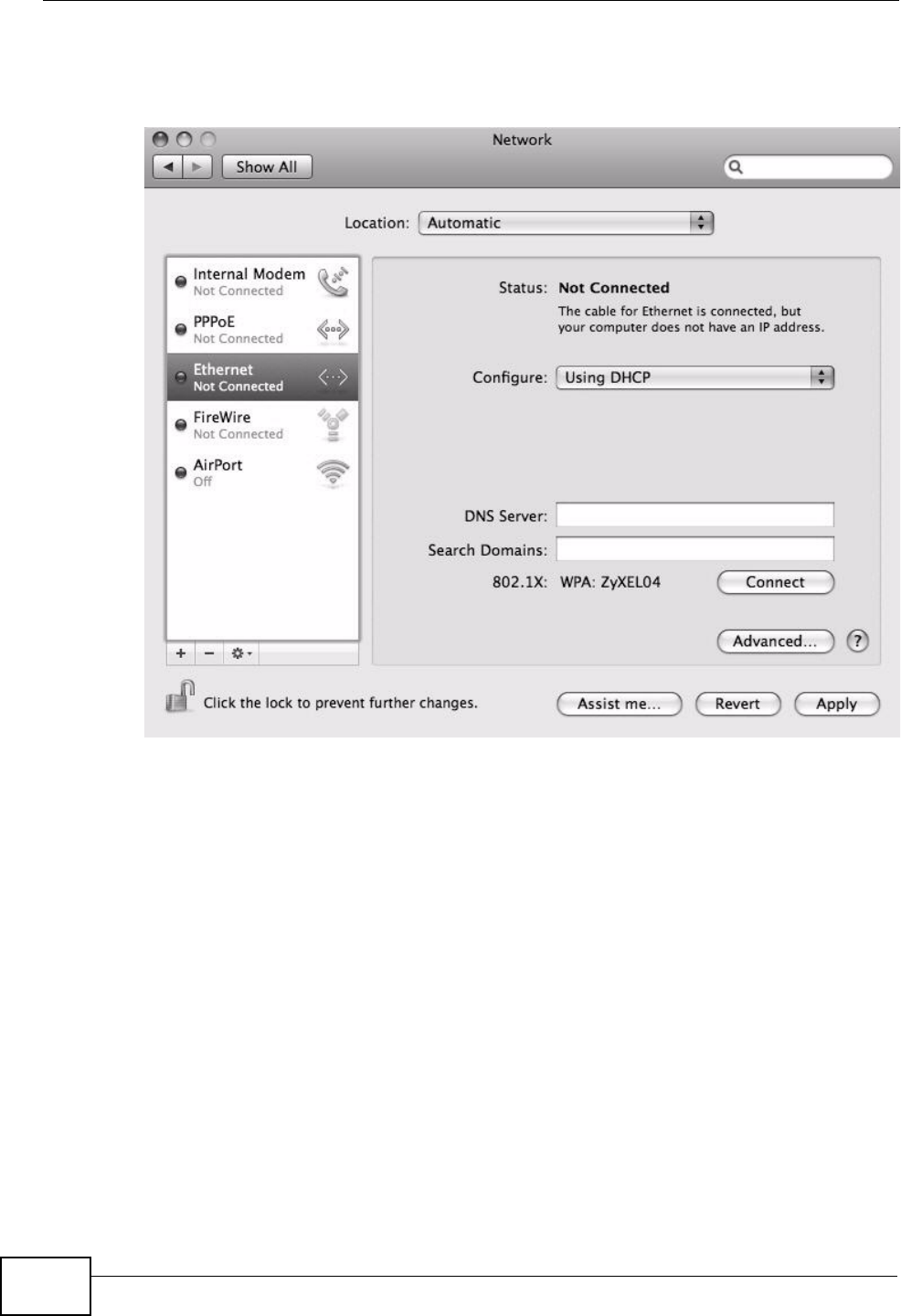
Appendix B Setting Up Your Computer’s IP Address
P-2612HNU(L)-FxF User’s Guide
334
3When the Network preferences pane opens, select Ethernet from the list of
available connection types.
Figure 165 Mac OS X 10.5: Network Preferences > Ethernet
4From the Configure list, select Using DHCP for dynamically assigned settings.
5For statically assigned settings, do the following:
• From the Configure list, select Manually.
• In the IP Address field, enter your IP address.
• In the Subnet Mask field, enter your subnet mask.
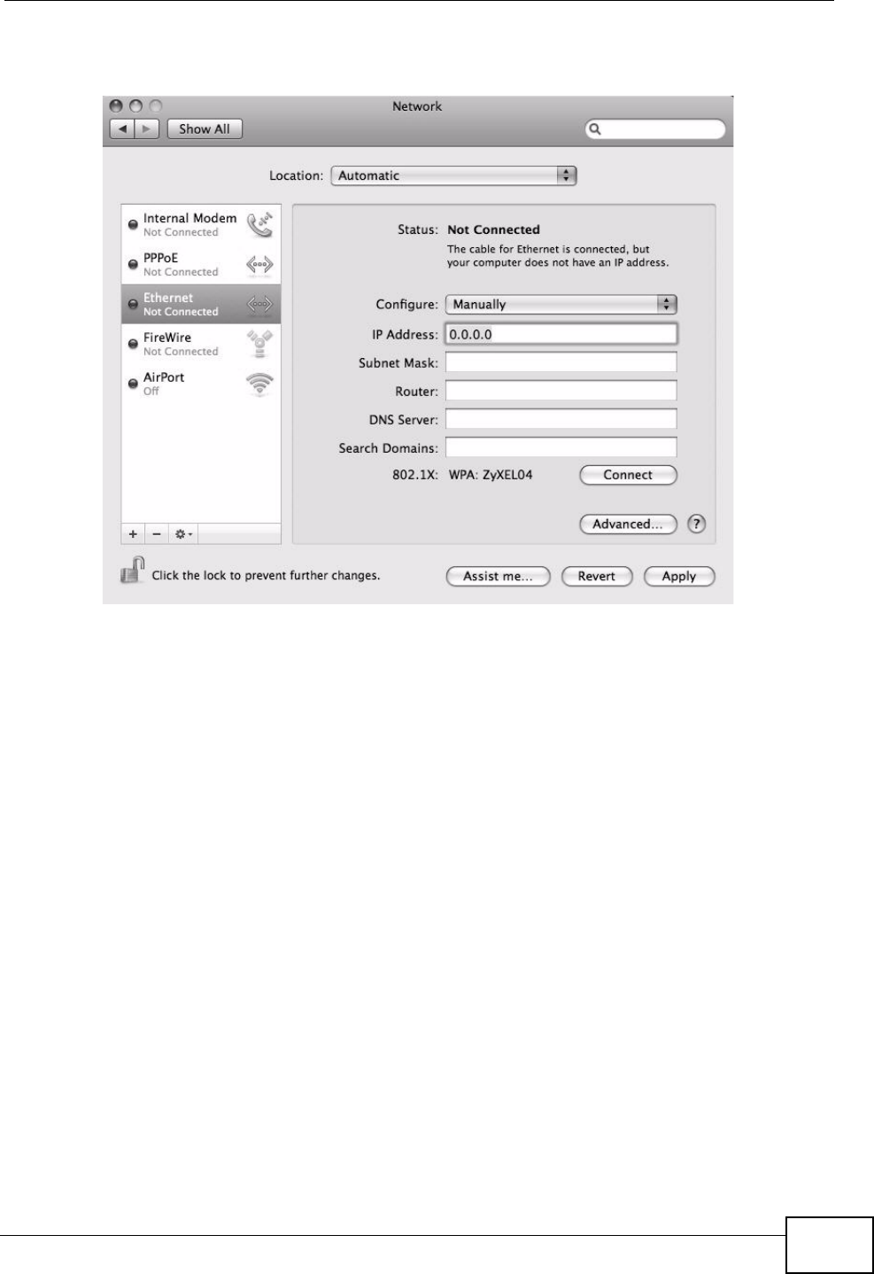
Appendix B Setting Up Your Computer’s IP Address
P-2612HNU(L)-FxF User’s Guide 335
• In the Router field, enter the IP address of your ZyXEL Device.
Figure 166 Mac OS X 10.5: Network Preferences > Ethernet
6Click Apply and close the window.
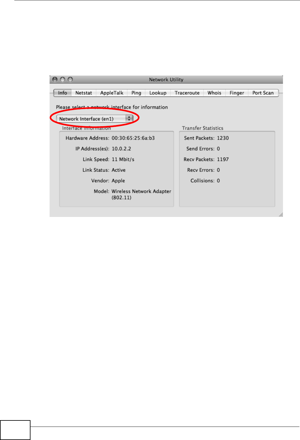
Appendix B Setting Up Your Computer’s IP Address
P-2612HNU(L)-FxF User’s Guide
336
Verifying Settings
Check your TCP/IP properties by clicking Applications > Utilities > Network
Utilities, and then selecting the appropriate Network interface from the Info
tab.
Figure 167 Mac OS X 10.5: Network Utility
Linux: Ubuntu 8 (GNOME)
This section shows you how to configure your computer’s TCP/IP settings in the
GNU Object Model Environment (GNOME) using the Ubuntu 8 Linux distribution.
The procedure, screens and file locations may vary depending on your specific
distribution, release version, and individual configuration. The following screens
use the default Ubuntu 8 installation.
Note: Make sure you are logged in as the root administrator.
Follow the steps below to configure your computer IP address in GNOME:
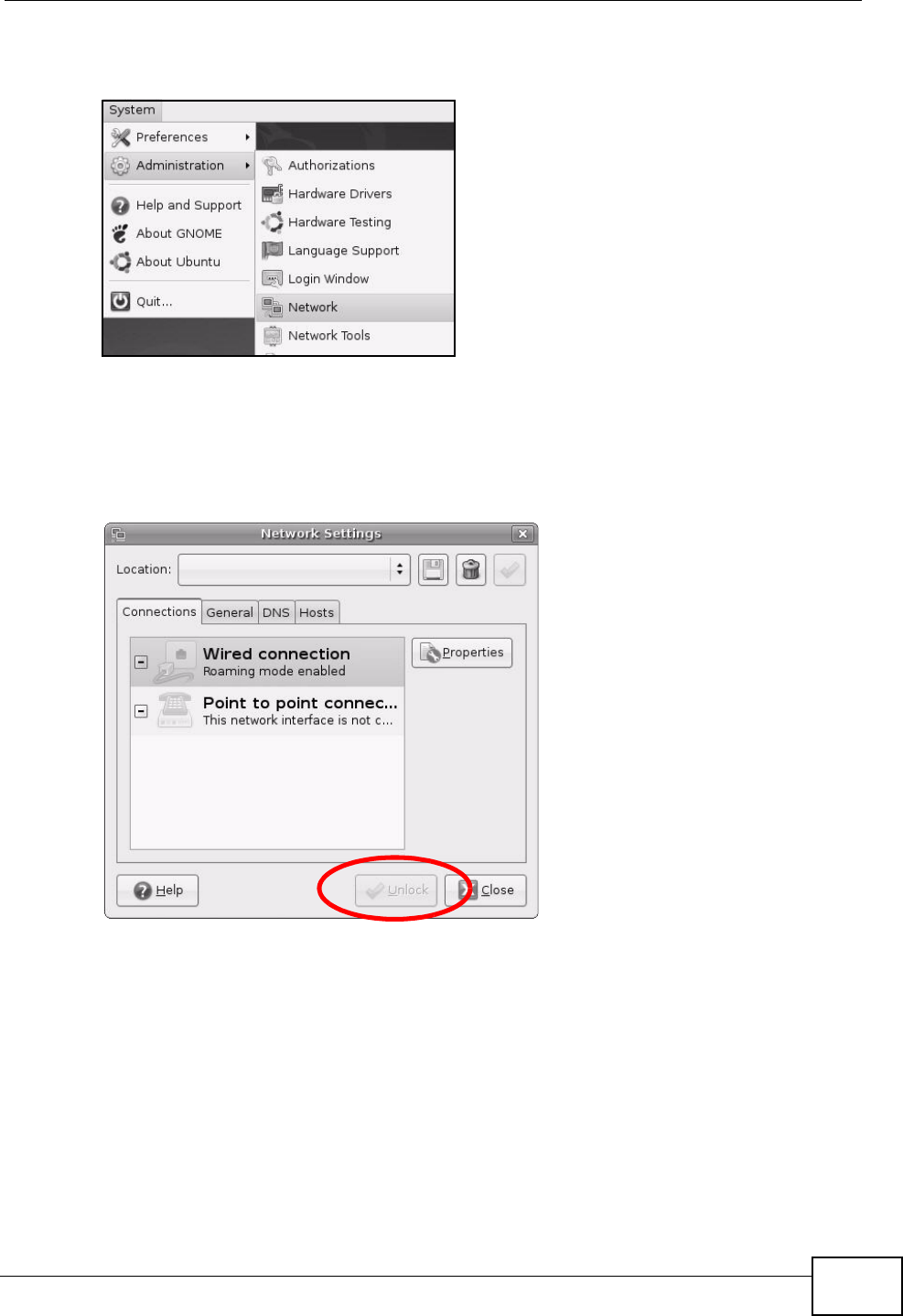
Appendix B Setting Up Your Computer’s IP Address
P-2612HNU(L)-FxF User’s Guide 337
1Click System > Administration > Network.
Figure 168 Ubuntu 8: System > Administration Menu
2When the Network Settings window opens, click Unlock to open the
Authenticate window. (By default, the Unlock button is greyed out until clicked.)
You cannot make changes to your configuration unless you first enter your admin
password.
Figure 169 Ubuntu 8: Network Settings > Connections
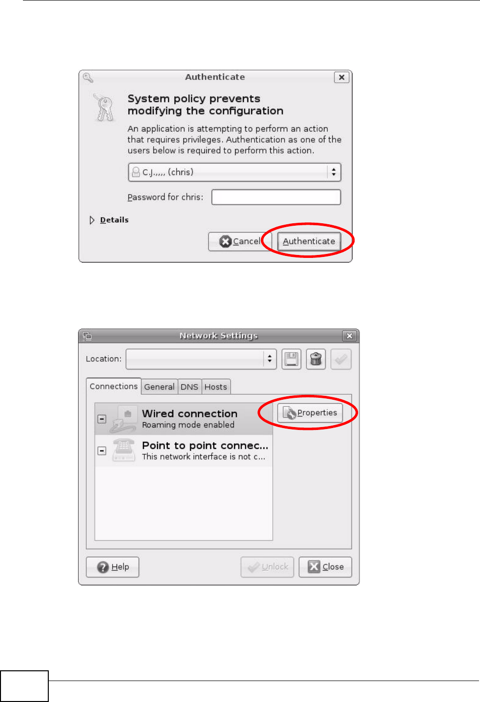
Appendix B Setting Up Your Computer’s IP Address
P-2612HNU(L)-FxF User’s Guide
338
3In the Authenticate window, enter your admin account name and password then
click the Authenticate button.
Figure 170 Ubuntu 8: Administrator Account Authentication
4In the Network Settings window, select the connection that you want to
configure, then click Properties.
Figure 171 Ubuntu 8: Network Settings > Connections
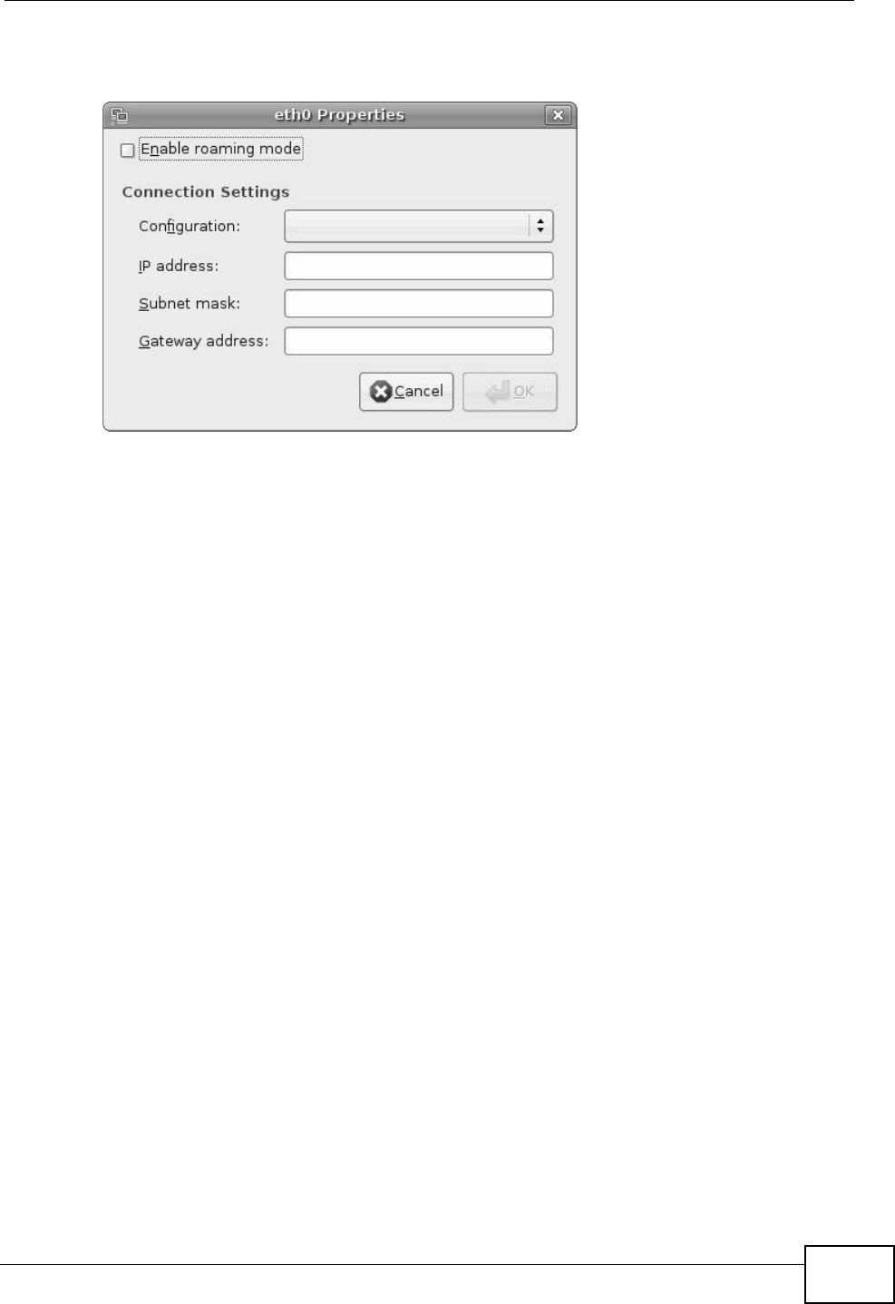
Appendix B Setting Up Your Computer’s IP Address
P-2612HNU(L)-FxF User’s Guide 339
5The Properties dialog box opens.
Figure 172 Ubuntu 8: Network Settings > Properties
• In the Configuration list, select Automatic Configuration (DHCP) if you
have a dynamic IP address.
• In the Configuration list, select Static IP address if you have a static IP
address. Fill in the IP address, Subnet mask, and Gateway address fields.
6Click OK to save the changes and close the Properties dialog box and return to
the Network Settings screen.
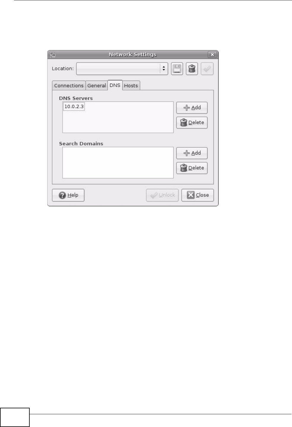
Appendix B Setting Up Your Computer’s IP Address
P-2612HNU(L)-FxF User’s Guide
340
7If you know your DNS server IP address(es), click the DNS tab in the Network
Settings window and then enter the DNS server information in the fields
provided.
Figure 173 Ubuntu 8: Network Settings > DNS
8Click the Close button to apply the changes.
Verifying Settings
Check your TCP/IP properties by clicking System > Administration > Network
Tools, and then selecting the appropriate Network device from the Devices
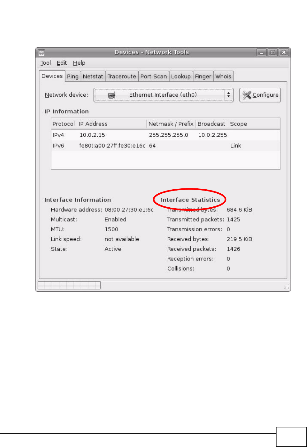
Appendix B Setting Up Your Computer’s IP Address
P-2612HNU(L)-FxF User’s Guide 341
tab. The Interface Statistics column shows data if your connection is working
properly.
Figure 174 Ubuntu 8: Network Tools
Linux: openSUSE 10.3 (KDE)
This section shows you how to configure your computer’s TCP/IP settings in the K
Desktop Environment (KDE) using the openSUSE 10.3 Linux distribution. The
procedure, screens and file locations may vary depending on your specific
distribution, release version, and individual configuration. The following screens
use the default openSUSE 10.3 installation.
Note: Make sure you are logged in as the root administrator.
Follow the steps below to configure your computer IP address in the KDE:
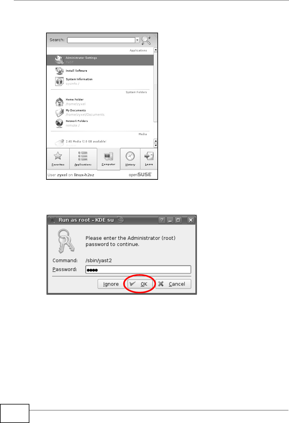
Appendix B Setting Up Your Computer’s IP Address
P-2612HNU(L)-FxF User’s Guide
342
1Click K Menu > Computer > Administrator Settings (YaST).
Figure 175 openSUSE 10.3: K Menu > Computer Menu
2When the Run as Root - KDE su dialog opens, enter the admin password and
click OK.
Figure 176 openSUSE 10.3: K Menu > Computer Menu
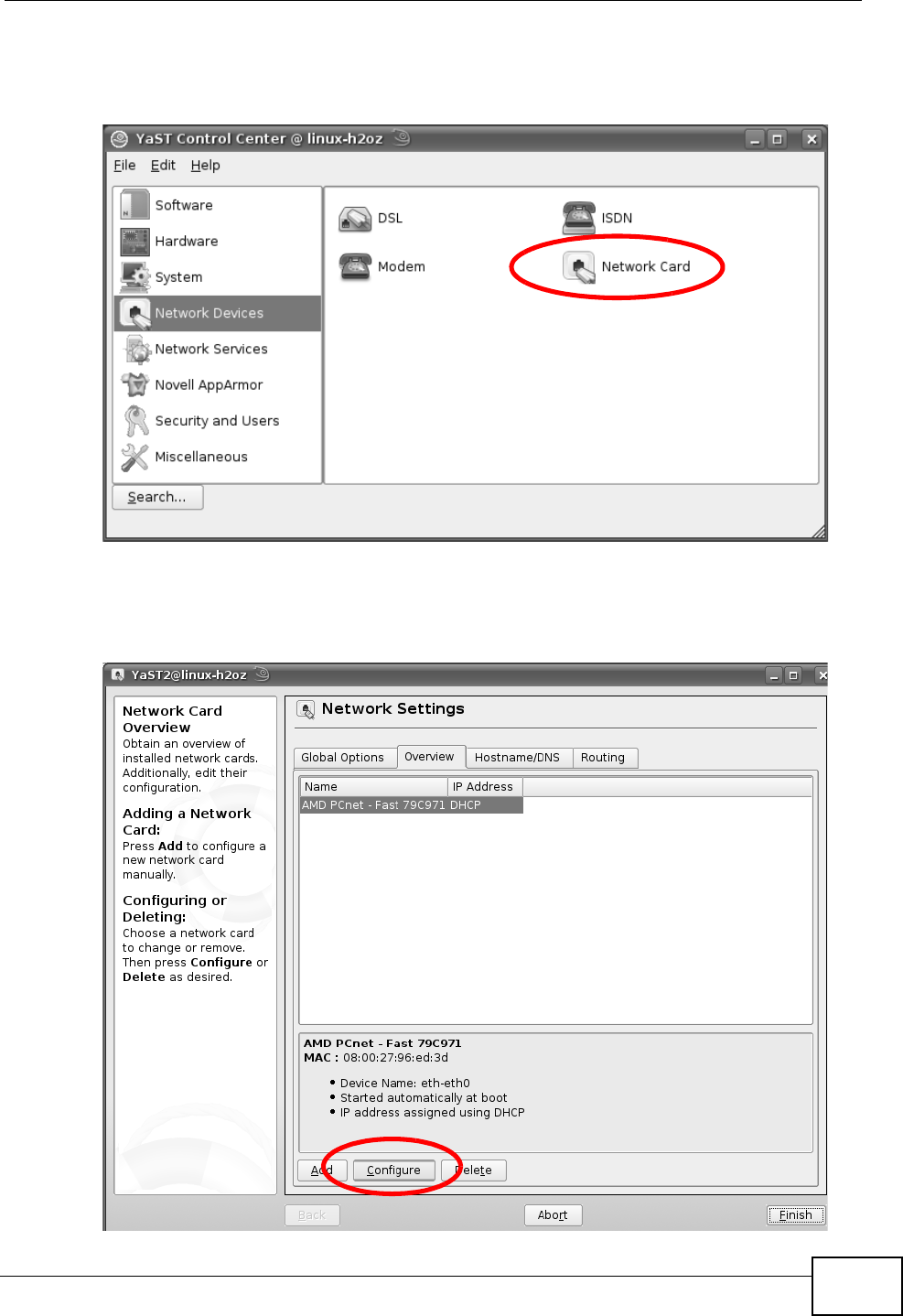
Appendix B Setting Up Your Computer’s IP Address
P-2612HNU(L)-FxF User’s Guide 343
3When the YaST Control Center window opens, select Network Devices and
then click the Network Card icon.
Figure 177 openSUSE 10.3: YaST Control Center
4When the Network Settings window opens, click the Overview tab, select the
appropriate connection Name from the list, and then click the Configure button.
Figure 178 openSUSE 10.3: Network Settings
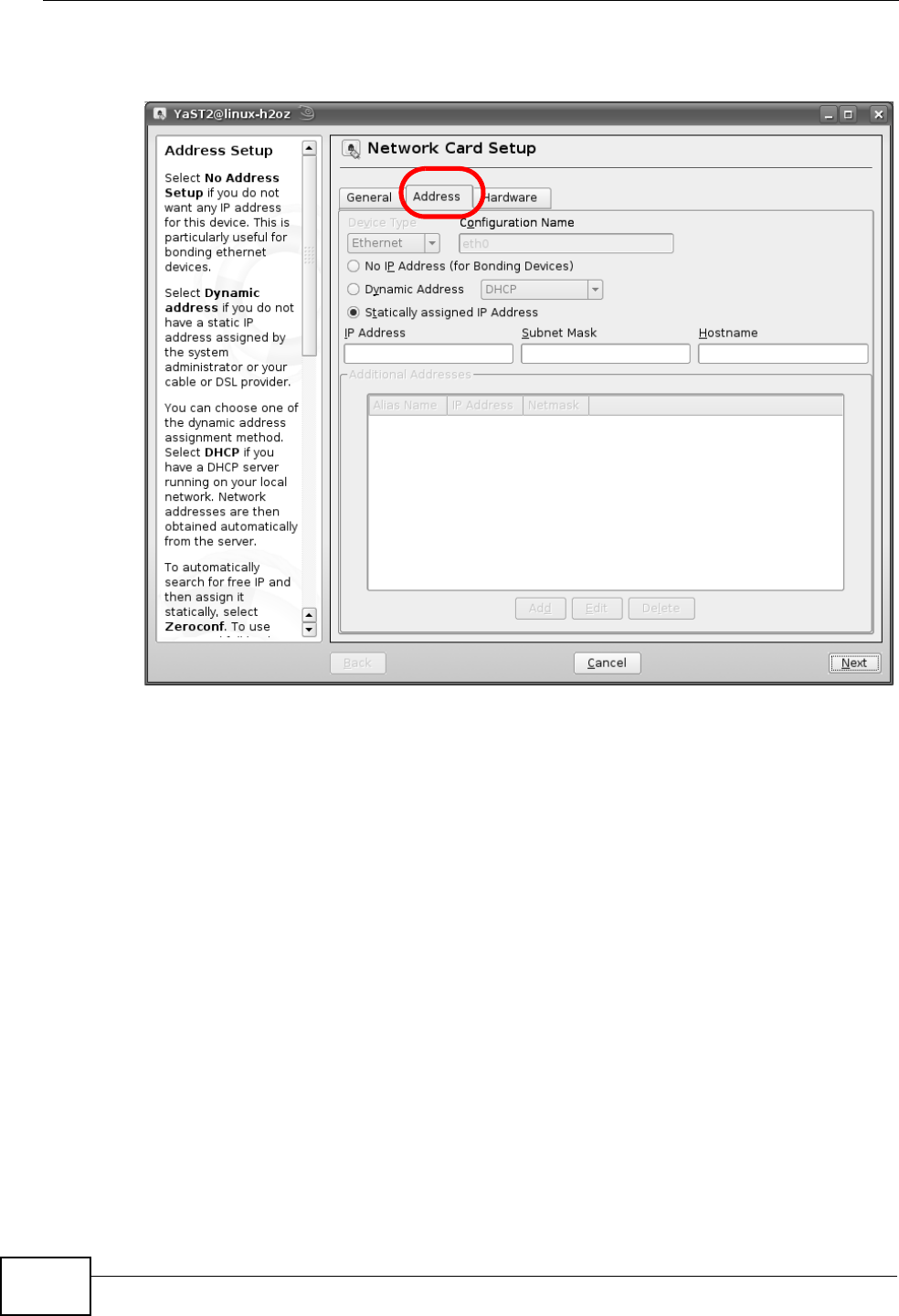
Appendix B Setting Up Your Computer’s IP Address
P-2612HNU(L)-FxF User’s Guide
344
5When the Network Card Setup window opens, click the Address tab
Figure 179 openSUSE 10.3: Network Card Setup
6Select Dynamic Address (DHCP) if you have a dynamic IP address.
Select Statically assigned IP Address if you have a static IP address. Fill in the
IP address, Subnet mask, and Hostname fields.
7Click Next to save the changes and close the Network Card Setup window.
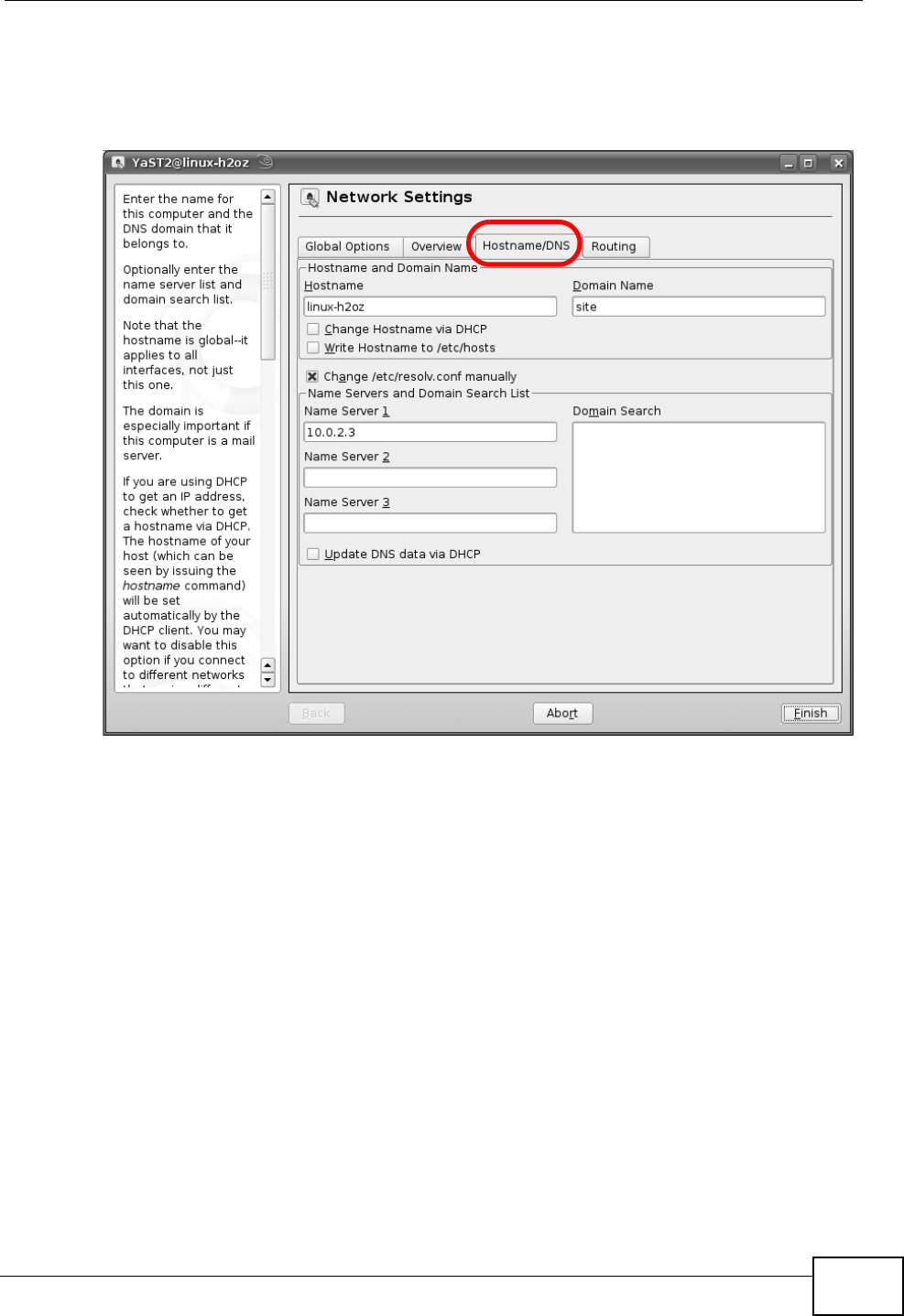
Appendix B Setting Up Your Computer’s IP Address
P-2612HNU(L)-FxF User’s Guide 345
8If you know your DNS server IP address(es), click the Hostname/DNS tab in
Network Settings and then enter the DNS server information in the fields
provided.
Figure 180 openSUSE 10.3: Network Settings
9Click Finish to save your settings and close the window.
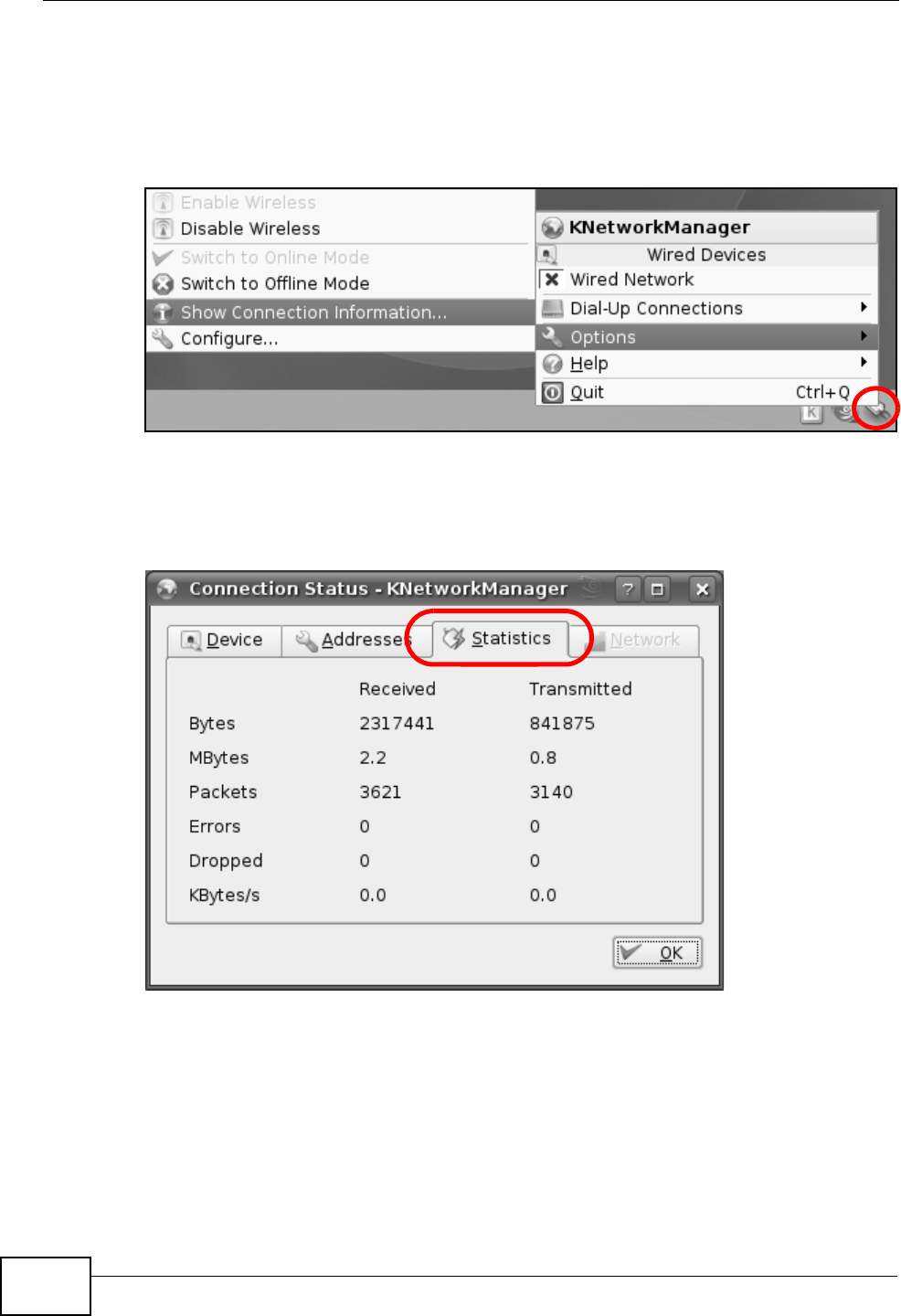
Appendix B Setting Up Your Computer’s IP Address
P-2612HNU(L)-FxF User’s Guide
346
Verifying Settings
Click the KNetwork Manager icon on the Task bar to check your TCP/IP
properties. From the Options sub-menu, select Show Connection Information.
Figure 181 openSUSE 10.3: KNetwork Manager
When the Connection Status - KNetwork Manager window opens, click the
Statistics tab to see if your connection is working properly.
Figure 182 openSUSE: Connection Status - KNetwork Manager
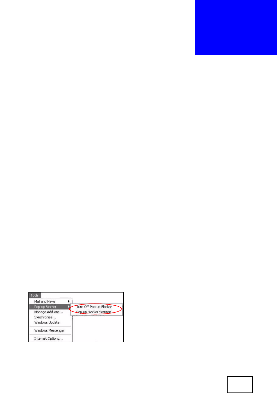
P-2612HNU(L)-FxF User’s Guide 347
APPENDIX C
Pop-up Windows, JavaScript
and Java Permissions
In order to use the web configurator you need to allow:
• Web browser pop-up windows from your device.
• JavaScript (enabled by default).
• Java permissions (enabled by default).
Note: Internet Explorer 6 screens are used here. Screens for other Internet Explorer
versions may vary.
Internet Explorer Pop-up Blockers
You may have to disable pop-up blocking to log into your device.
Either disable pop-up blocking (enabled by default in Windows XP SP (Service
Pack) 2) or allow pop-up blocking and create an exception for your device’s IP
address.
Disable Pop-up Blockers
1In Internet Explorer, select Tools, Pop-up Blocker and then select Turn Off
Pop-up Blocker.
Figure 183 Pop-up Blocker
You can also check if pop-up blocking is disabled in the Pop-up Blocker section in
the Privacy tab.
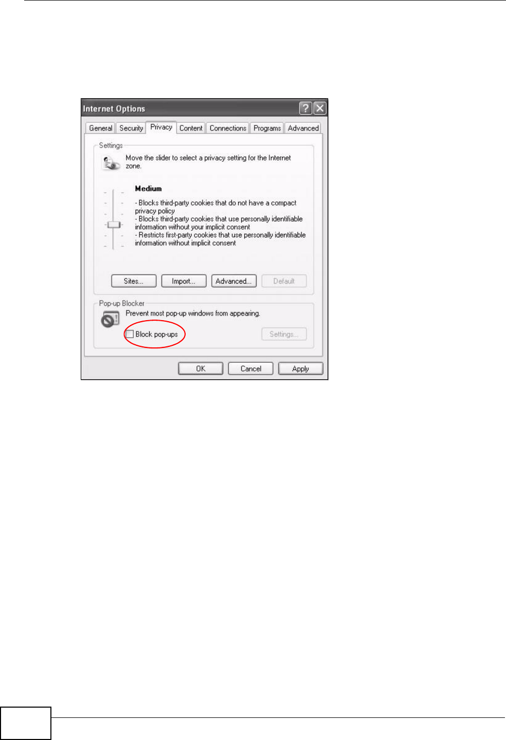
Appendix C Pop-up Windows, JavaScript and Java Permissions
P-2612HNU(L)-FxF User’s Guide
348
1In Internet Explorer, select Tools, Internet Options, Privacy.
2Clear the Block pop-ups check box in the Pop-up Blocker section of the screen.
This disables any web pop-up blockers you may have enabled.
Figure 184 Internet Options: Privacy
3Click Apply to save this setting.
Enable Pop-up Blockers with Exceptions
Alternatively, if you only want to allow pop-up windows from your device, see the
following steps.
1In Internet Explorer, select Tools, Internet Options and then the Privacy tab.
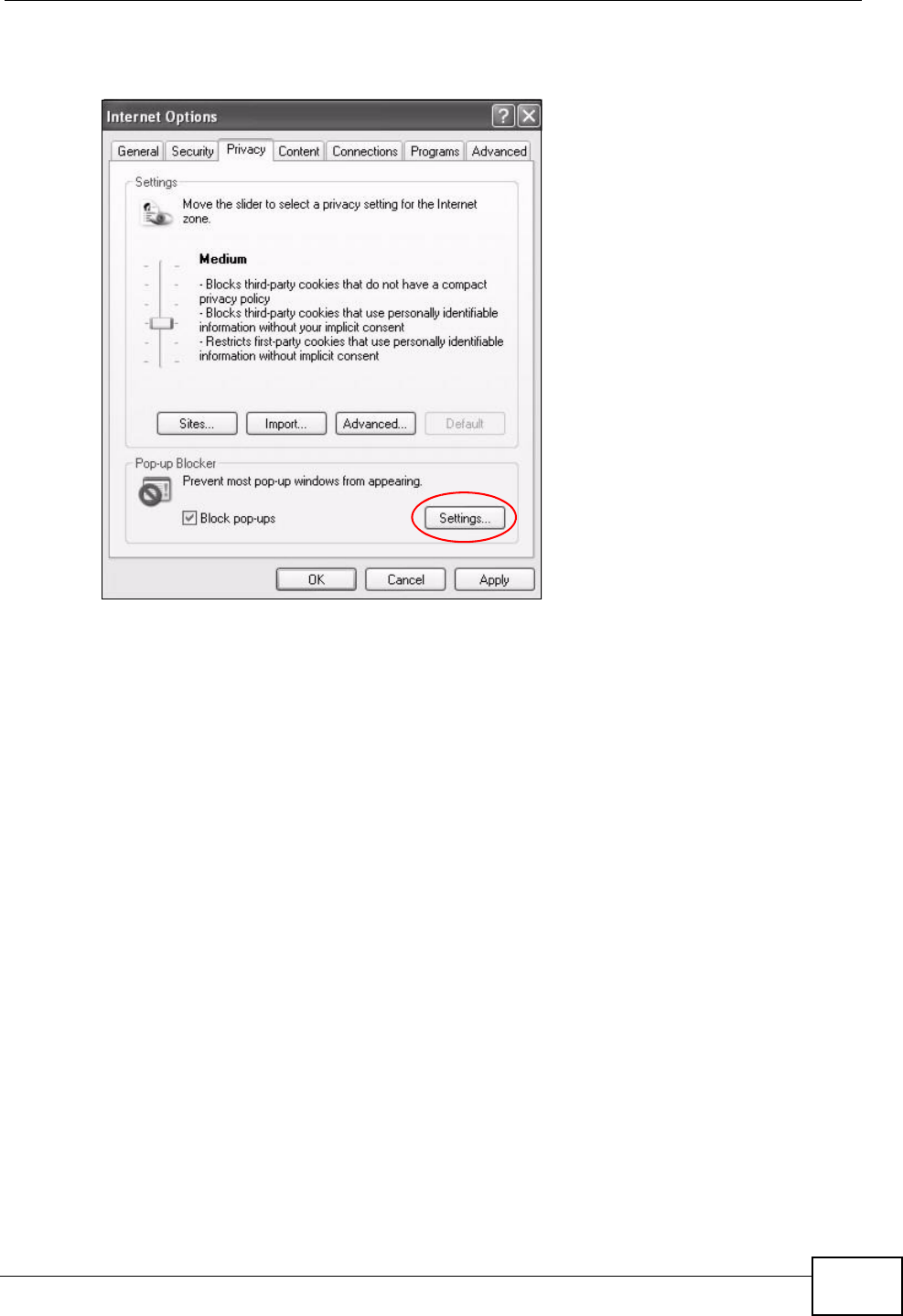
Appendix C Pop-up Windows, JavaScript and Java Permissions
P-2612HNU(L)-FxF User’s Guide 349
2Select Settings…to open the Pop-up Blocker Settings screen.
Figure 185 Internet Options: Privacy
3Type the IP address of your device (the web page that you do not want to have
blocked) with the prefix “http://”. For example, http://192.168.167.1.
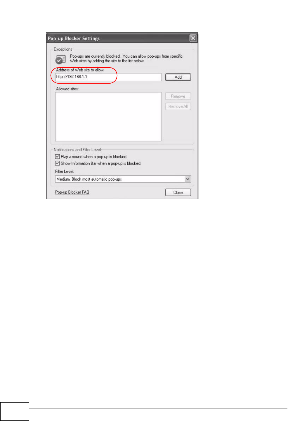
Appendix C Pop-up Windows, JavaScript and Java Permissions
P-2612HNU(L)-FxF User’s Guide
350
4Click Add to move the IP address to the list of Allowed sites.
Figure 186 Pop-up Blocker Settings
5Click Close to return to the Privacy screen.
6Click Apply to save this setting.
JavaScript
If pages of the web configurator do not display properly in Internet Explorer, check
that JavaScript are allowed.
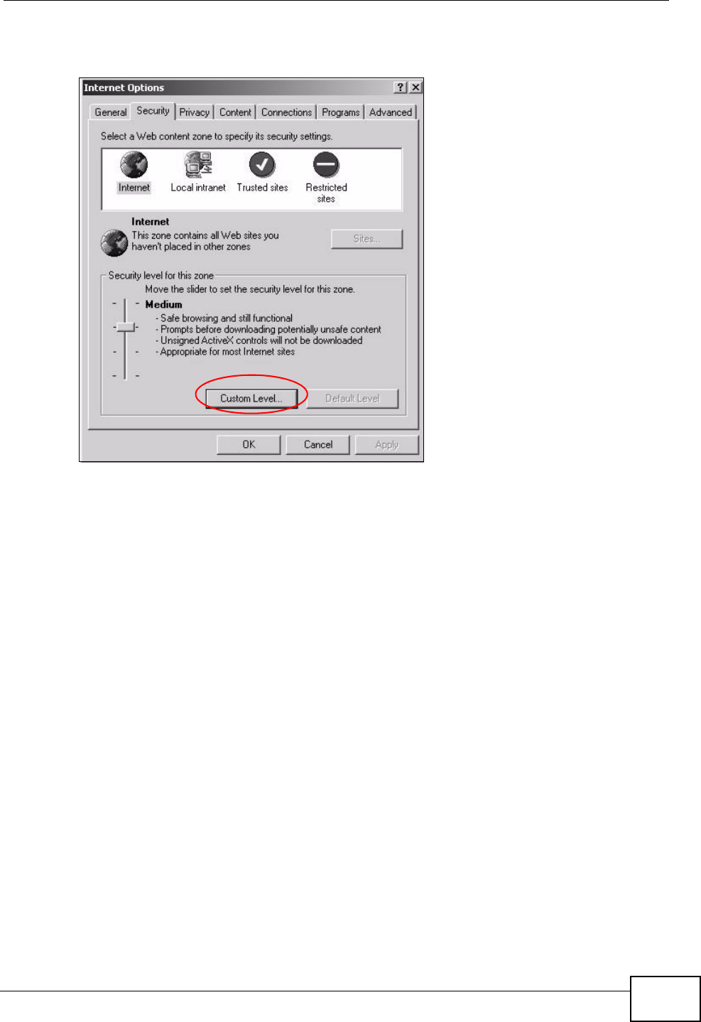
Appendix C Pop-up Windows, JavaScript and Java Permissions
P-2612HNU(L)-FxF User’s Guide 351
1In Internet Explorer, click Tools, Internet Options and then the Security tab.
Figure 187 Internet Options: Security
2Click the Custom Level... button.
3Scroll down to Scripting.
4Under Active scripting make sure that Enable is selected (the default).
5Under Scripting of Java applets make sure that Enable is selected (the
default).
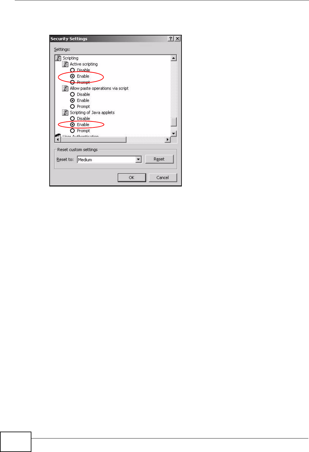
Appendix C Pop-up Windows, JavaScript and Java Permissions
P-2612HNU(L)-FxF User’s Guide
352
6Click OK to close the window.
Figure 188 Security Settings - Java Scripting
Java Permissions
1From Internet Explorer, click Tools, Internet Options and then the Security
tab.
2Click the Custom Level... button.
3Scroll down to Microsoft VM.
4Under Java permissions make sure that a safety level is selected.
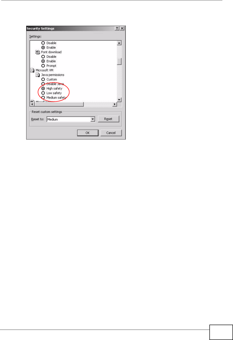
Appendix C Pop-up Windows, JavaScript and Java Permissions
P-2612HNU(L)-FxF User’s Guide 353
5Click OK to close the window.
Figure 189 Security Settings - Java
JAVA (Sun)
1From Internet Explorer, click Tools, Internet Options and then the Advanced
tab.
2Make sure that Use Java 2 for <applet> under Java (Sun) is selected.
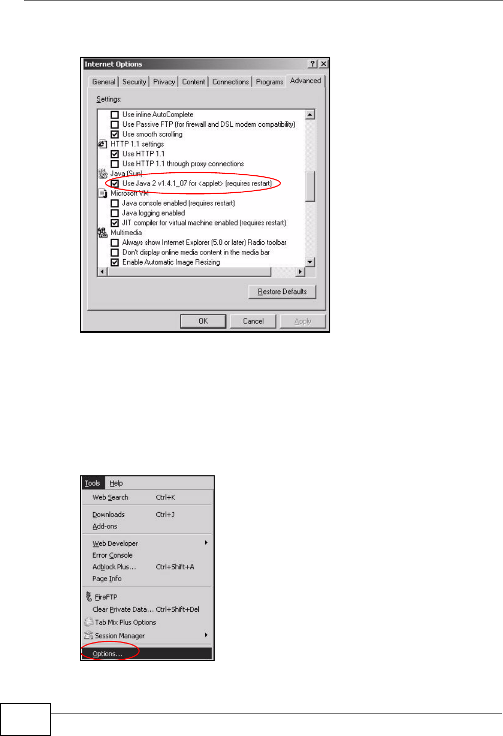
Appendix C Pop-up Windows, JavaScript and Java Permissions
P-2612HNU(L)-FxF User’s Guide
354
3Click OK to close the window.
Figure 190 Java (Sun)
Mozilla Firefox
Mozilla Firefox 2.0 screens are used here. Screens for other versions may vary.
You can enable Java, JavaScript and pop-ups in one screen. Click Tools, then click
Options in the screen that appears.
Figure 191 Mozilla Firefox: Tools > Options
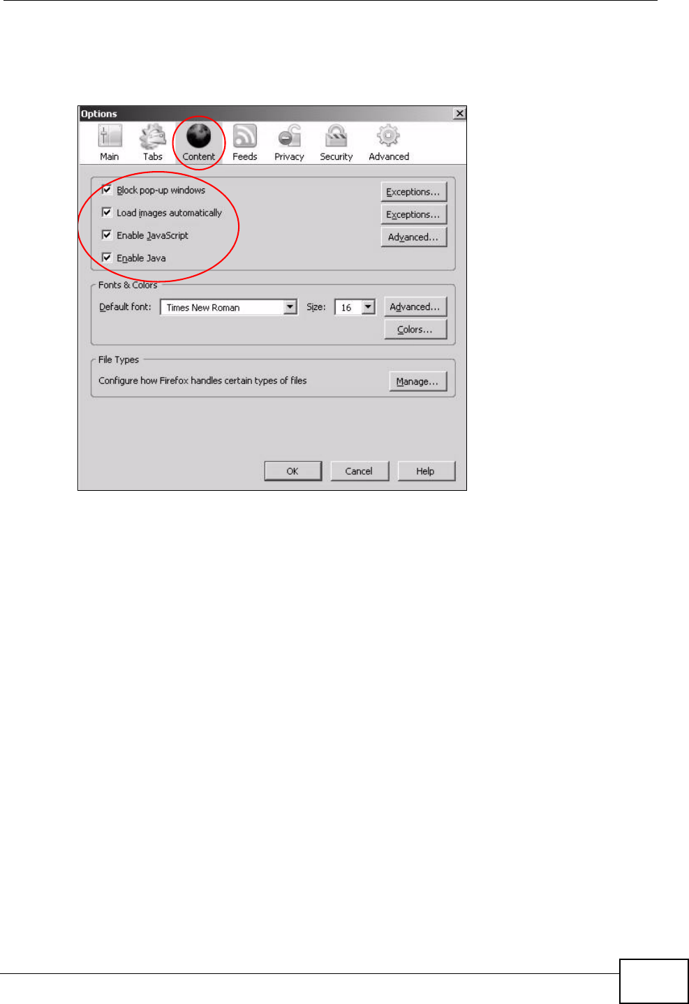
Appendix C Pop-up Windows, JavaScript and Java Permissions
P-2612HNU(L)-FxF User’s Guide 355
Click Content.to show the screen below. Select the check boxes as shown in the
following screen.
Figure 192 Mozilla Firefox Content Security

Appendix C Pop-up Windows, JavaScript and Java Permissions
P-2612HNU(L)-FxF User’s Guide
356
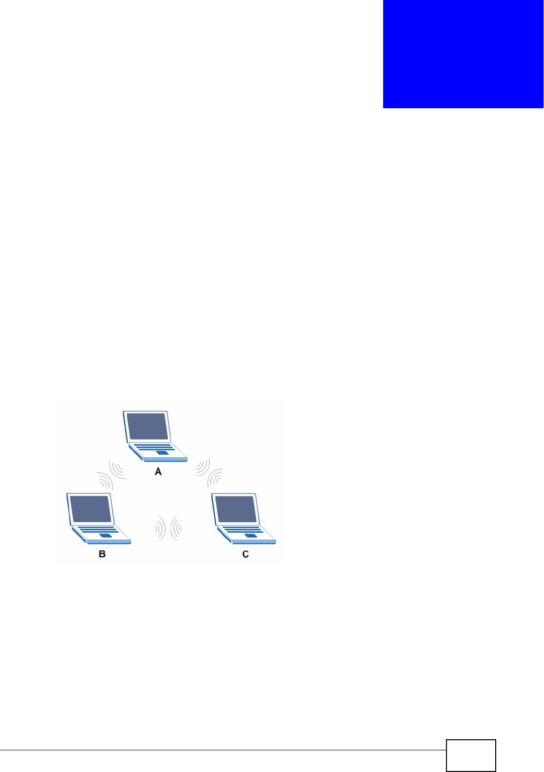
P-2612HNU(L)-FxF User’s Guide 357
APPENDIX D
Wireless LANs
Wireless LAN Topologies
This section discusses ad-hoc and infrastructure wireless LAN topologies.
Ad-hoc Wireless LAN Configuration
The simplest WLAN configuration is an independent (Ad-hoc) WLAN that connects
a set of computers with wireless adapters (A, B, C). Any time two or more wireless
adapters are within range of each other, they can set up an independent network,
which is commonly referred to as an ad-hoc network or Independent Basic Service
Set (IBSS). The following diagram shows an example of notebook computers
using wireless adapters to form an ad-hoc wireless LAN.
Figure 193 Peer-to-Peer Communication in an Ad-hoc Network
BSS
A Basic Service Set (BSS) exists when all communications between wireless
clients or between a wireless client and a wired network client go through one
access point (AP).
Intra-BSS traffic is traffic between wireless clients in the BSS. When Intra-BSS is
enabled, wireless client A and B can access the wired network and communicate
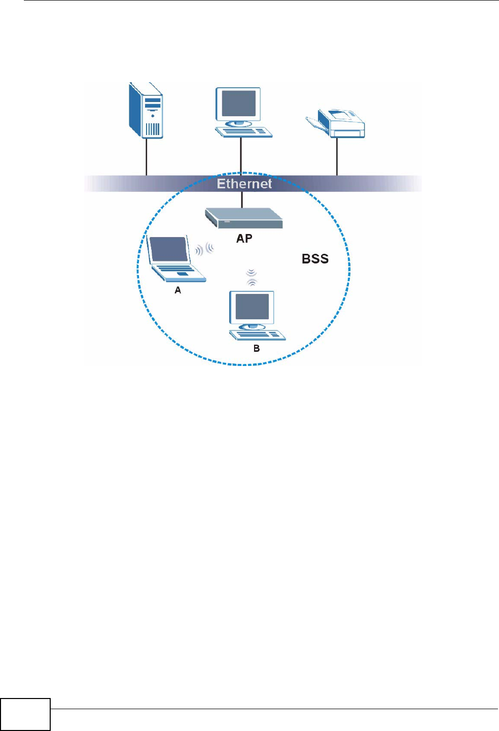
Appendix D Wireless LANs
P-2612HNU(L)-FxF User’s Guide
358
with each other. When Intra-BSS is disabled, wireless client A and B can still
access the wired network but cannot communicate with each other.
Figure 194 Basic Service Set
ESS
An Extended Service Set (ESS) consists of a series of overlapping BSSs, each
containing an access point, with each access point connected together by a wired
network. This wired connection between APs is called a Distribution System (DS).
This type of wireless LAN topology is called an Infrastructure WLAN. The Access
Points not only provide communication with the wired network but also mediate
wireless network traffic in the immediate neighborhood.
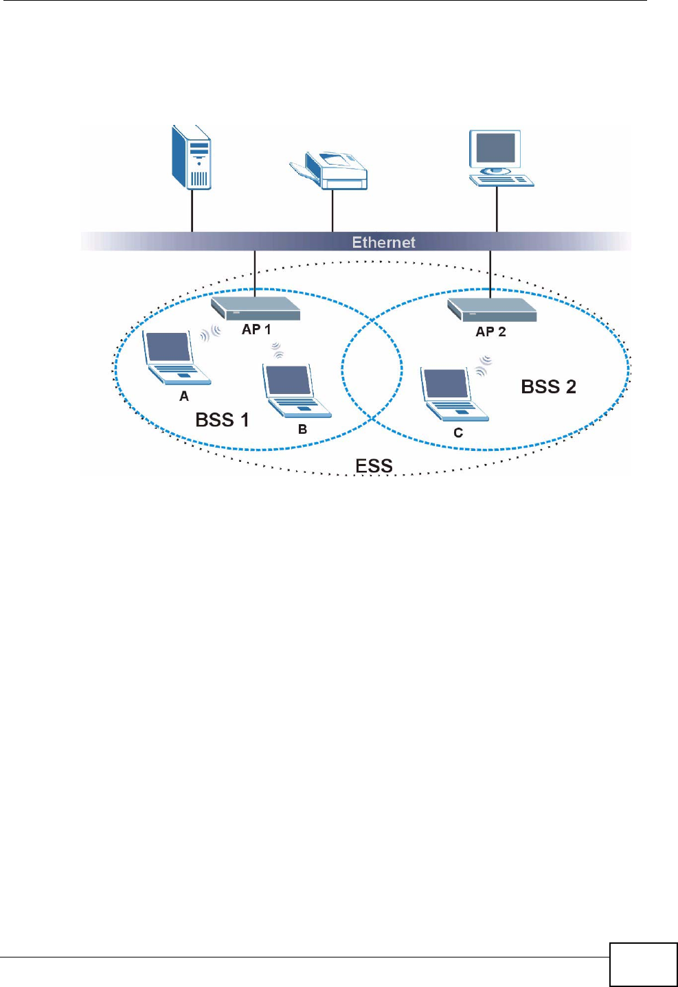
Appendix D Wireless LANs
P-2612HNU(L)-FxF User’s Guide 359
An ESSID (ESS IDentification) uniquely identifies each ESS. All access points and
their associated wireless clients within the same ESS must have the same ESSID
in order to communicate.
Figure 195 Infrastructure WLAN
Channel
A channel is the radio frequency(ies) used by wireless devices to transmit and
receive data. Channels available depend on your geographical area. You may have
a choice of channels (for your region) so you should use a channel different from
an adjacent AP (access point) to reduce interference. Interference occurs when
radio signals from different access points overlap causing interference and
degrading performance.
Adjacent channels partially overlap however. To avoid interference due to overlap,
your AP should be on a channel at least five channels away from a channel that an
adjacent AP is using. For example, if your region has 11 channels and an adjacent
AP is using channel 1, then you need to select a channel between 6 or 11.
RTS/CTS
A hidden node occurs when two stations are within range of the same access
point, but are not within range of each other. The following figure illustrates a
hidden node. Both stations (STA) are within range of the access point (AP) or
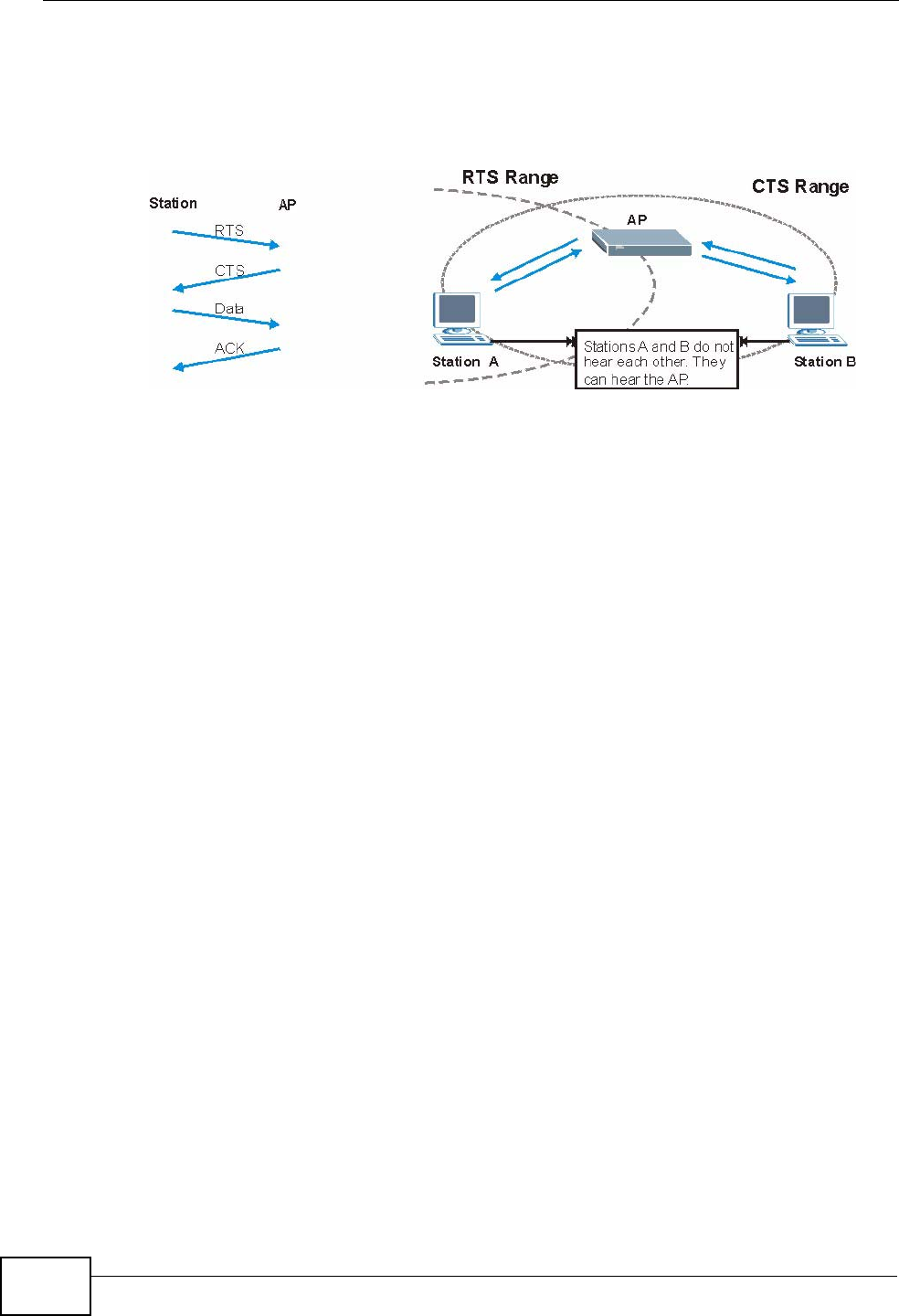
Appendix D Wireless LANs
P-2612HNU(L)-FxF User’s Guide
360
wireless gateway, but out-of-range of each other, so they cannot "hear" each
other, that is they do not know if the channel is currently being used. Therefore,
they are considered hidden from each other.
Figure 196 RTS/CTS
When station Asends data to the AP, it might not know that the station B is
already using the channel. If these two stations send data at the same time,
collisions may occur when both sets of data arrive at the AP at the same time,
resulting in a loss of messages for both stations.
RTS/CTS is designed to prevent collisions due to hidden nodes. An RTS/CTS
defines the biggest size data frame you can send before an RTS (Request To
Send)/CTS (Clear to Send) handshake is invoked.
When a data frame exceeds the RTS/CTS value you set (between 0 to 2432
bytes), the station that wants to transmit this frame must first send an RTS
(Request To Send) message to the AP for permission to send it. The AP then
responds with a CTS (Clear to Send) message to all other stations within its range
to notify them to defer their transmission. It also reserves and confirms with the
requesting station the time frame for the requested transmission.
Stations can send frames smaller than the specified RTS/CTS directly to the AP
without the RTS (Request To Send)/CTS (Clear to Send) handshake.
You should only configure RTS/CTS if the possibility of hidden nodes exists on
your network and the "cost" of resending large frames is more than the extra
network overhead involved in the RTS (Request To Send)/CTS (Clear to Send)
handshake.
If the RTS/CTS value is greater than the Fragmentation Threshold value (see
next), then the RTS (Request To Send)/CTS (Clear to Send) handshake will never
occur as data frames will be fragmented before they reach RTS/CTS size.
Note: Enabling the RTS Threshold causes redundant network overhead that could
negatively affect the throughput performance instead of providing a remedy.

Appendix D Wireless LANs
P-2612HNU(L)-FxF User’s Guide 361
Fragmentation Threshold
A Fragmentation Threshold is the maximum data fragment size (between 256
and 2432 bytes) that can be sent in the wireless network before the AP will
fragment the packet into smaller data frames.
A large Fragmentation Threshold is recommended for networks not prone to
interference while you should set a smaller threshold for busy networks or
networks that are prone to interference.
If the Fragmentation Threshold value is smaller than the RTS/CTS value (see
previously) you set then the RTS (Request To Send)/CTS (Clear to Send)
handshake will never occur as data frames will be fragmented before they reach
RTS/CTS size.
Preamble Type
Preamble is used to signal that data is coming to the receiver. Short and long refer
to the length of the synchronization field in a packet.
Short preamble increases performance as less time sending preamble means
more time for sending data. All IEEE 802.11 compliant wireless adapters support
long preamble, but not all support short preamble.
Use long preamble if you are unsure what preamble mode other wireless devices
on the network support, and to provide more reliable communications in busy
wireless networks.
Use short preamble if you are sure all wireless devices on the network support it,
and to provide more efficient communications.
Use the dynamic setting to automatically use short preamble when all wireless
devices on the network support it, otherwise the ZyXEL Device uses long
preamble.
Note: The wireless devices MUST use the same preamble mode in order to
communicate.
IEEE 802.11g Wireless LAN
IEEE 802.11g is fully compatible with the IEEE 802.11b standard. This means an
IEEE 802.11b adapter can interface directly with an IEEE 802.11g access point
(and vice versa) at 11 Mbps or lower depending on range. IEEE 802.11g has
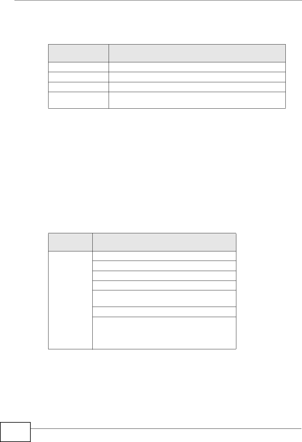
Appendix D Wireless LANs
P-2612HNU(L)-FxF User’s Guide
362
several intermediate rate steps between the maximum and minimum data rates.
The IEEE 802.11g data rate and modulation are as follows:
Wireless Security Overview
Wireless security is vital to your network to protect wireless communication
between wireless clients, access points and the wired network.
Wireless security methods available on the ZyXEL Device are data encryption,
wireless client authentication, restricting access by device MAC address and hiding
the ZyXEL Device identity.
The following figure shows the relative effectiveness of these wireless security
methods available on your ZyXEL Device.
Note: You must enable the same wireless security settings on the ZyXEL Device and
on all wireless clients that you want to associate with it.
Table 99 IEEE 802.11g
DATA RATE
(MBPS) MODULATION
1 DBPSK (Differential Binary Phase Shift Keyed)
2 DQPSK (Differential Quadrature Phase Shift Keying)
5.5 / 11 CCK (Complementary Code Keying)
6/9/12/18/24/36/
48/54
OFDM (Orthogonal Frequency Division Multiplexing)
Table 100 Wireless Security Levels
SECURITY
LEVEL SECURITY TYPE
Least
Secure
Most Secure
Unique SSID (Default)
Unique SSID with Hide SSID Enabled
MAC Address Filtering
WEP Encryption
IEEE802.1x EAP with RADIUS Server
Authentication
Wi-Fi Protected Access (WPA)
WPA2

Appendix D Wireless LANs
P-2612HNU(L)-FxF User’s Guide 363
IEEE 802.1x
In June 2001, the IEEE 802.1x standard was designed to extend the features of
IEEE 802.11 to support extended authentication as well as providing additional
accounting and control features. It is supported by Windows XP and a number of
network devices. Some advantages of IEEE 802.1x are:
• User based identification that allows for roaming.
• Support for RADIUS (Remote Authentication Dial In User Service, RFC 2138,
2139) for centralized user profile and accounting management on a network
RADIUS server.
• Support for EAP (Extensible Authentication Protocol, RFC 2486) that allows
additional authentication methods to be deployed with no changes to the access
point or the wireless clients.
RADIUS
RADIUS is based on a client-server model that supports authentication,
authorization and accounting. The access point is the client and the server is the
RADIUS server. The RADIUS server handles the following tasks:
• Authentication
Determines the identity of the users.
• Authorization
Determines the network services available to authenticated users once they are
connected to the network.
• Accounting
Keeps track of the client’s network activity.
RADIUS is a simple package exchange in which your AP acts as a message relay
between the wireless client and the network RADIUS server.
Types of RADIUS Messages
The following types of RADIUS messages are exchanged between the access point
and the RADIUS server for user authentication:
• Access-Request
Sent by an access point requesting authentication.
• Access-Reject
Sent by a RADIUS server rejecting access.
• Access-Accept
Sent by a RADIUS server allowing access.

Appendix D Wireless LANs
P-2612HNU(L)-FxF User’s Guide
364
• Access-Challenge
Sent by a RADIUS server requesting more information in order to allow access.
The access point sends a proper response from the user and then sends another
Access-Request message.
The following types of RADIUS messages are exchanged between the access point
and the RADIUS server for user accounting:
• Accounting-Request
Sent by the access point requesting accounting.
• Accounting-Response
Sent by the RADIUS server to indicate that it has started or stopped accounting.
In order to ensure network security, the access point and the RADIUS server use a
shared secret key, which is a password, they both know. The key is not sent over
the network. In addition to the shared key, password information exchanged is
also encrypted to protect the network from unauthorized access.
Types of EAP Authentication
This section discusses some popular authentication types: EAP-MD5, EAP-TLS,
EAP-TTLS, PEAP and LEAP. Your wireless LAN device may not support all
authentication types.
EAP (Extensible Authentication Protocol) is an authentication protocol that runs on
top of the IEEE 802.1x transport mechanism in order to support multiple types of
user authentication. By using EAP to interact with an EAP-compatible RADIUS
server, an access point helps a wireless station and a RADIUS server perform
authentication.
The type of authentication you use depends on the RADIUS server and an
intermediary AP(s) that supports IEEE 802.1x. .
For EAP-TLS authentication type, you must first have a wired connection to the
network and obtain the certificate(s) from a certificate authority (CA). A certificate
(also called digital IDs) can be used to authenticate users and a CA issues
certificates and guarantees the identity of each certificate owner.
EAP-MD5 (Message-Digest Algorithm 5)
MD5 authentication is the simplest one-way authentication method. The
authentication server sends a challenge to the wireless client. The wireless client
‘proves’ that it knows the password by encrypting the password with the challenge
and sends back the information. Password is not sent in plain text.

Appendix D Wireless LANs
P-2612HNU(L)-FxF User’s Guide 365
However, MD5 authentication has some weaknesses. Since the authentication
server needs to get the plaintext passwords, the passwords must be stored. Thus
someone other than the authentication server may access the password file. In
addition, it is possible to impersonate an authentication server as MD5
authentication method does not perform mutual authentication. Finally, MD5
authentication method does not support data encryption with dynamic session
key. You must configure WEP encryption keys for data encryption.
EAP-TLS (Transport Layer Security)
With EAP-TLS, digital certifications are needed by both the server and the wireless
clients for mutual authentication. The server presents a certificate to the client.
After validating the identity of the server, the client sends a different certificate to
the server. The exchange of certificates is done in the open before a secured
tunnel is created. This makes user identity vulnerable to passive attacks. A digital
certificate is an electronic ID card that authenticates the sender’s identity.
However, to implement EAP-TLS, you need a Certificate Authority (CA) to handle
certificates, which imposes a management overhead.
EAP-TTLS (Tunneled Transport Layer Service)
EAP-TTLS is an extension of the EAP-TLS authentication that uses certificates for
only the server-side authentications to establish a secure connection. Client
authentication is then done by sending username and password through the
secure connection, thus client identity is protected. For client authentication, EAP-
TTLS supports EAP methods and legacy authentication methods such as PAP,
CHAP, MS-CHAP and MS-CHAP v2.
PEAP (Protected EAP)
Like EAP-TTLS, server-side certificate authentication is used to establish a secure
connection, then use simple username and password methods through the
secured connection to authenticate the clients, thus hiding client identity.
However, PEAP only supports EAP methods, such as EAP-MD5, EAP-MSCHAPv2
and EAP-GTC (EAP-Generic Token Card), for client authentication. EAP-GTC is
implemented only by Cisco.
LEAP
LEAP (Lightweight Extensible Authentication Protocol) is a Cisco implementation of
IEEE 802.1x.
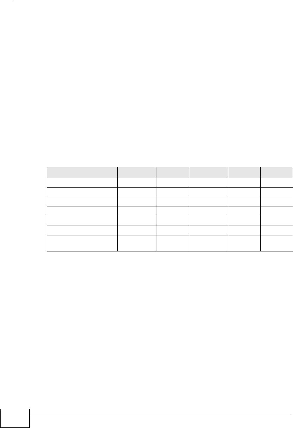
Appendix D Wireless LANs
P-2612HNU(L)-FxF User’s Guide
366
Dynamic WEP Key Exchange
The AP maps a unique key that is generated with the RADIUS server. This key
expires when the wireless connection times out, disconnects or reauthentication
times out. A new WEP key is generated each time reauthentication is performed.
If this feature is enabled, it is not necessary to configure a default encryption key
in the wireless security configuration screen. You may still configure and store
keys, but they will not be used while dynamic WEP is enabled.
Note: EAP-MD5 cannot be used with Dynamic WEP Key Exchange
For added security, certificate-based authentications (EAP-TLS, EAP-TTLS and
PEAP) use dynamic keys for data encryption. They are often deployed in corporate
environments, but for public deployment, a simple user name and password pair
is more practical. The following table is a comparison of the features of
authentication types.
WPA and WPA2
Wi-Fi Protected Access (WPA) is a subset of the IEEE 802.11i standard. WPA2
(IEEE 802.11i) is a wireless security standard that defines stronger encryption,
authentication and key management than WPA.
Key differences between WPA or WPA2 and WEP are improved data encryption and
user authentication.
If both an AP and the wireless clients support WPA2 and you have an external
RADIUS server, use WPA2 for stronger data encryption. If you don't have an
external RADIUS server, you should use WPA2-PSK (WPA2-Pre-Shared Key) that
only requires a single (identical) password entered into each access point, wireless
gateway and wireless client. As long as the passwords match, a wireless client will
be granted access to a WLAN.
Table 101 Comparison of EAP Authentication Types
EAP-MD5 EAP-TLS EAP-TTLS PEAP LEAP
Mutual Authentication No Yes Yes Yes Yes
Certificate – Client No Yes Optional Optional No
Certificate – Server No Yes Yes Yes No
Dynamic Key Exchange No Yes Yes Yes Yes
Credential Integrity None Strong Strong Strong Moderate
Deployment Difficulty Easy Hard Moderate Moderate Moderate
Client Identity
Protection
No No Yes Yes No

Appendix D Wireless LANs
P-2612HNU(L)-FxF User’s Guide 367
If the AP or the wireless clients do not support WPA2, just use WPA or WPA-PSK
depending on whether you have an external RADIUS server or not.
Select WEP only when the AP and/or wireless clients do not support WPA or WPA2.
WEP is less secure than WPA or WPA2.
Encryption
Both WPA and WPA2 improve data encryption by using Temporal Key Integrity
Protocol (TKIP), Message Integrity Check (MIC) and IEEE 802.1x. WPA and WPA2
use Advanced Encryption Standard (AES) in the Counter mode with Cipher block
chaining Message authentication code Protocol (CCMP) to offer stronger
encryption than TKIP.
TKIP uses 128-bit keys that are dynamically generated and distributed by the
authentication server. AES (Advanced Encryption Standard) is a block cipher that
uses a 256-bit mathematical algorithm called Rijndael. They both include a per-
packet key mixing function, a Message Integrity Check (MIC) named Michael, an
extended initialization vector (IV) with sequencing rules, and a re-keying
mechanism.
WPA and WPA2 regularly change and rotate the encryption keys so that the same
encryption key is never used twice.
The RADIUS server distributes a Pairwise Master Key (PMK) key to the AP that
then sets up a key hierarchy and management system, using the PMK to
dynamically generate unique data encryption keys to encrypt every data packet
that is wirelessly communicated between the AP and the wireless clients. This all
happens in the background automatically.
The Message Integrity Check (MIC) is designed to prevent an attacker from
capturing data packets, altering them and resending them. The MIC provides a
strong mathematical function in which the receiver and the transmitter each
compute and then compare the MIC. If they do not match, it is assumed that the
data has been tampered with and the packet is dropped.
By generating unique data encryption keys for every data packet and by creating
an integrity checking mechanism (MIC), with TKIP and AES it is more difficult to
decrypt data on a Wi-Fi network than WEP and difficult for an intruder to break
into the network.
The encryption mechanisms used for WPA(2) and WPA(2)-PSK are the same. The
only difference between the two is that WPA(2)-PSK uses a simple common
password, instead of user-specific credentials. The common-password approach
makes WPA(2)-PSK susceptible to brute-force password-guessing attacks but it’s
still an improvement over WEP as it employs a consistent, single, alphanumeric
password to derive a PMK which is used to generate unique temporal encryption

Appendix D Wireless LANs
P-2612HNU(L)-FxF User’s Guide
368
keys. This prevent all wireless devices sharing the same encryption keys. (a
weakness of WEP)
User Authentication
WPA and WPA2 apply IEEE 802.1x and Extensible Authentication Protocol (EAP) to
authenticate wireless clients using an external RADIUS database. WPA2 reduces
the number of key exchange messages from six to four (CCMP 4-way handshake)
and shortens the time required to connect to a network. Other WPA2
authentication features that are different from WPA include key caching and pre-
authentication. These two features are optional and may not be supported in all
wireless devices.
Key caching allows a wireless client to store the PMK it derived through a
successful authentication with an AP. The wireless client uses the PMK when it tries
to connect to the same AP and does not need to go with the authentication
process again.
Pre-authentication enables fast roaming by allowing the wireless client (already
connecting to an AP) to perform IEEE 802.1x authentication with another AP
before connecting to it.
Wireless Client WPA Supplicants
A wireless client supplicant is the software that runs on an operating system
instructing the wireless client how to use WPA. At the time of writing, the most
widely available supplicant is the WPA patch for Windows XP, Funk Software's
Odyssey client.
The Windows XP patch is a free download that adds WPA capability to Windows
XP's built-in "Zero Configuration" wireless client. However, you must run Windows
XP to use it.
WPA(2) with RADIUS Application Example
To set up WPA(2), you need the IP address of the RADIUS server, its port number
(default is 1812), and the RADIUS shared secret. A WPA(2) application example
with an external RADIUS server looks as follows. "A" is the RADIUS server. "DS" is
the distribution system.
1The AP passes the wireless client's authentication request to the RADIUS server.
2The RADIUS server then checks the user's identification against its database and
grants or denies network access accordingly.
3A 256-bit Pairwise Master Key (PMK) is derived from the authentication process by
the RADIUS server and the client.
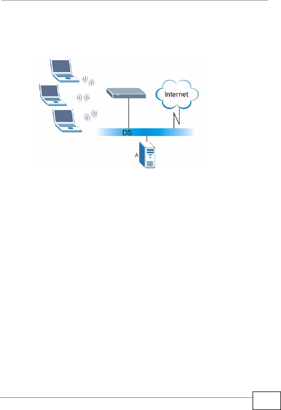
Appendix D Wireless LANs
P-2612HNU(L)-FxF User’s Guide 369
4The RADIUS server distributes the PMK to the AP. The AP then sets up a key
hierarchy and management system, using the PMK to dynamically generate
unique data encryption keys. The keys are used to encrypt every data packet that
is wirelessly communicated between the AP and the wireless clients.
Figure 197 WPA(2) with RADIUS Application Example
WPA(2)-PSK Application Example
A WPA(2)-PSK application looks as follows.
1First enter identical passwords into the AP and all wireless clients. The Pre-Shared
Key (PSK) must consist of between 8 and 63 ASCII characters or 64 hexadecimal
characters (including spaces and symbols).
2The AP checks each wireless client's password and allows it to join the network
only if the password matches.
3The AP and wireless clients generate a common PMK (Pairwise Master Key). The
key itself is not sent over the network, but is derived from the PSK and the SSID.
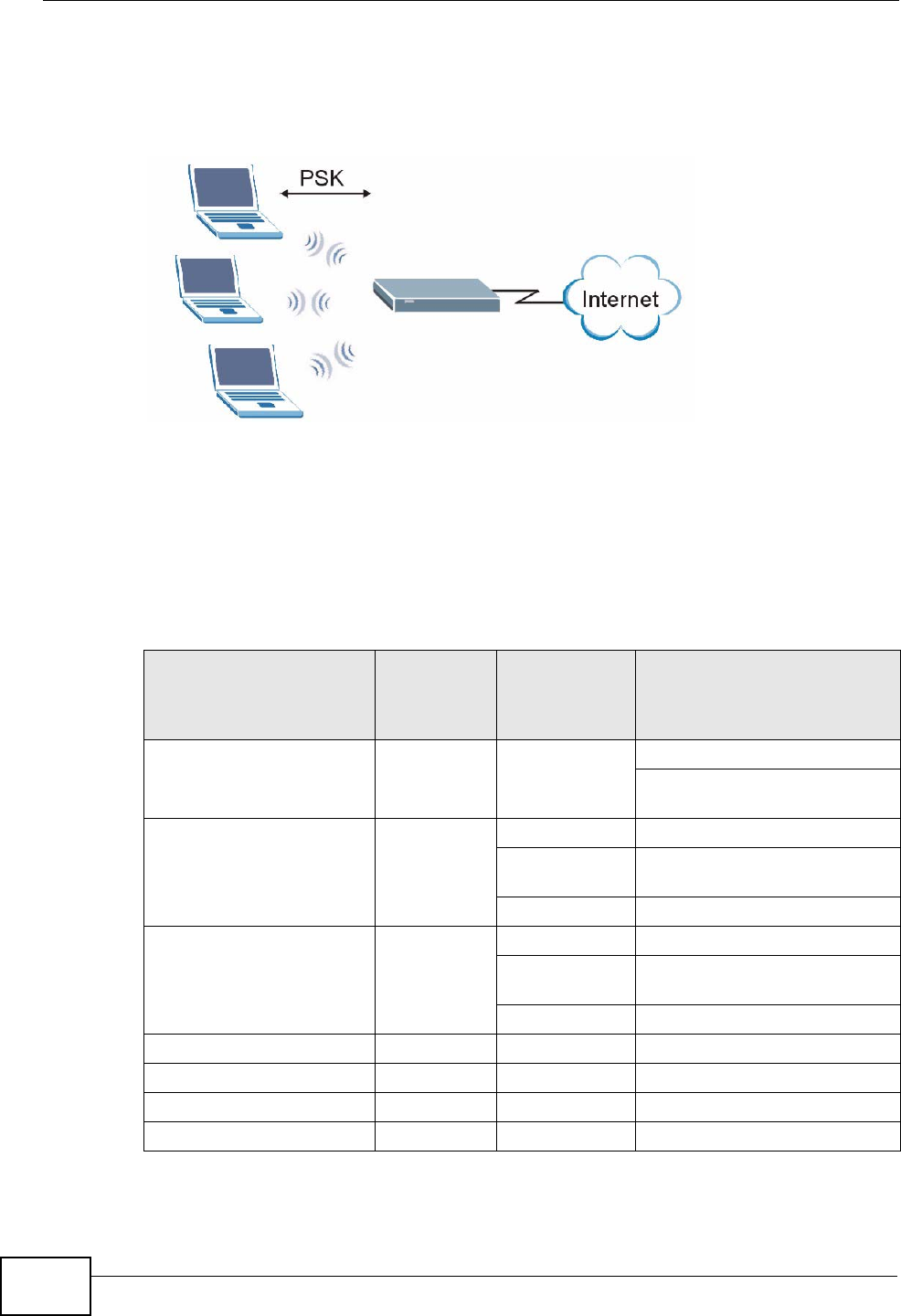
Appendix D Wireless LANs
P-2612HNU(L)-FxF User’s Guide
370
4The AP and wireless clients use the TKIP or AES encryption process, the PMK and
information exchanged in a handshake to create temporal encryption keys. They
use these keys to encrypt data exchanged between them.
Figure 198 WPA(2)-PSK Authentication
Security Parameters Summary
Refer to this table to see what other security parameters you should configure for
each authentication method or key management protocol type. MAC address
filters are not dependent on how you configure these security features.
Table 102 Wireless Security Relational Matrix
AUTHENTICATION
METHOD/ KEY
MANAGEMENT
PROTOCOL
ENCRYPTIO
N METHOD
ENTER
MANUAL KEY IEEE 802.1X
Open None No Disable
Enable without Dynamic WEP
Key
Open WEP No Enable with Dynamic WEP Key
Yes Enable without Dynamic WEP
Key
Yes Disable
Shared WEP No Enable with Dynamic WEP Key
Yes Enable without Dynamic WEP
Key
Yes Disable
WPA TKIP/AES No Enable
WPA-PSK TKIP/AES Yes Disable
WPA2 TKIP/AES No Enable
WPA2-PSK TKIP/AES Yes Disable

Appendix D Wireless LANs
P-2612HNU(L)-FxF User’s Guide 371
Antenna Overview
An antenna couples RF signals onto air. A transmitter within a wireless device
sends an RF signal to the antenna, which propagates the signal through the air.
The antenna also operates in reverse by capturing RF signals from the air.
Positioning the antennas properly increases the range and coverage area of a
wireless LAN.
Antenna Characteristics
Frequency
An antenna in the frequency of 2.4GHz (IEEE 802.11b and IEEE 802.11g) or 5GHz
(IEEE 802.11a) is needed to communicate efficiently in a wireless LAN
Radiation Pattern
A radiation pattern is a diagram that allows you to visualize the shape of the
antenna’s coverage area.
Antenna Gain
Antenna gain, measured in dB (decibel), is the increase in coverage within the RF
beam width. Higher antenna gain improves the range of the signal for better
communications.
For an indoor site, each 1 dB increase in antenna gain results in a range increase
of approximately 2.5%. For an unobstructed outdoor site, each 1dB increase in
gain results in a range increase of approximately 5%. Actual results may vary
depending on the network environment.
Antenna gain is sometimes specified in dBi, which is how much the antenna
increases the signal power compared to using an isotropic antenna. An isotropic
antenna is a theoretical perfect antenna that sends out radio signals equally well
in all directions. dBi represents the true gain that the antenna provides.
Types of Antennas for WLAN
There are two types of antennas used for wireless LAN applications.

Appendix D Wireless LANs
P-2612HNU(L)-FxF User’s Guide
372
• Omni-directional antennas send the RF signal out in all directions on a horizontal
plane. The coverage area is torus-shaped (like a donut) which makes these
antennas ideal for a room environment. With a wide coverage area, it is possible
to make circular overlapping coverage areas with multiple access points.
• Directional antennas concentrate the RF signal in a beam, like a flashlight does
with the light from its bulb. The angle of the beam determines the width of the
coverage pattern. Angles typically range from 20 degrees (very directional) to
120 degrees (less directional). Directional antennas are ideal for hallways and
outdoor point-to-point applications.
Positioning Antennas
In general, antennas should be mounted as high as practically possible and free of
obstructions. In point-to–point application, position both antennas at the same
height and in a direct line of sight to each other to attain the best performance.
For omni-directional antennas mounted on a table, desk, and so on, point the
antenna up. For omni-directional antennas mounted on a wall or ceiling, point the
antenna down. For a single AP application, place omni-directional antennas as
close to the center of the coverage area as possible.
For directional antennas, point the antenna in the direction of the desired
coverage area.
WiFi Protected Setup
Your ZyXEL Device supports WiFi Protected Setup (WPS), which is an easy way to
set up a secure wireless network. WPS is an industry standard specification,
defined by the WiFi Alliance.
WPS allows you to quickly set up a wireless network with strong security, without
having to configure security settings manually. Each WPS connection works
between two devices. Both devices must support WPS (check each device’s
documentation to make sure).
Depending on the devices you have, you can either press a button (on the device
itself, or in its configuration utility) or enter a PIN (a unique Personal Identification
Number that allows one device to authenticate the other) in each of the two
devices. When WPS is activated on a device, it has two minutes to find another
device that also has WPS activated. Then, the two devices connect and set up a
secure network by themselves.

Appendix D Wireless LANs
P-2612HNU(L)-FxF User’s Guide 373
Push Button Configuration
WPS Push Button Configuration (PBC) is initiated by pressing a button on each
WPS-enabled device, and allowing them to connect automatically. You do not need
to enter any information.
Not every WPS-enabled device has a physical WPS button. Some may have a WPS
PBC button in their configuration utilities instead of or in addition to the physical
button.
Take the following steps to set up WPS using the button.
1Ensure that the two devices you want to set up are within wireless range of one
another.
2Look for a WPS button on each device. If the device does not have one, log into its
configuration utility and locate the button (see the device’s User’s Guide for how to
do this - for the ZyXEL Device, see Section 6.4 on page 131).
3Press the button on one of the devices (it doesn’t matter which).
4Within two minutes, press the button on the other device. The registrar sends the
network name (SSID) and security key through an secure connection to the
enrollee.
If you need to make sure that WPS worked, check the list of associated wireless
clients in the AP’s configuration utility. If you see the wireless client in the list,
WPS was successful.
PIN Configuration
Each WPS-enabled device has its own PIN (Personal Identification Number). This
may either be static (it cannot be changed) or dynamic (you can change it to a
new random number by clicking on a button in the configuration interface).
When you use the PIN method, you must enter the enrollee’s PIN into the
registrar. Then, when WPS is activated on the enrollee, it presents its PIN to the
registrar. If the PIN matches, the registrar sends the network and security
information to the enrollee, allowing it to join the network.
The advantage of using the PIN method rather than the PBC method is that you
can ensure that the connection is established between the devices you specify, not
just the first two devices to activate WPS in the area. However, you need to log
into the configuration interfaces of both devices.
Take the following steps to set up WPS using the PIN method.

Appendix D Wireless LANs
P-2612HNU(L)-FxF User’s Guide
374
1Decide which device you want to be the registrar (usually the AP) and which you
want to be the enrollee (usually the client).
2Look for the enrollee’s WPS PIN; it may be displayed on the device. If you don’t
see it, log into the enrollee’s configuration interface and locate the PIN. Select the
PIN connection mode (not PBC connection mode). See the device’s User’s Guide
for how to do this - for the ZyXEL Device, see Section 6.4 on page 131.
3Log into the configuration utility of the registrar. Select the PIN connection mode
(not the PBC connection mode). Locate the place where you can enter the
enrollee’s PIN (if you are using the ZyXEL Device, see Section 6.4 on page 131).
Enter the PIN from the enrollee device.
4Activate WPS on both devices within two minutes.
Note: Use the configuration utility to activate WPS, not the push-button on the device
itself.
5On a computer connected to the wireless client, try to connect to the Internet. If
you can connect, WPS was successful.
If you cannot connect, check the list of associated wireless clients in the AP’s
configuration utility. If you see the wireless client in the list, WPS was successful.
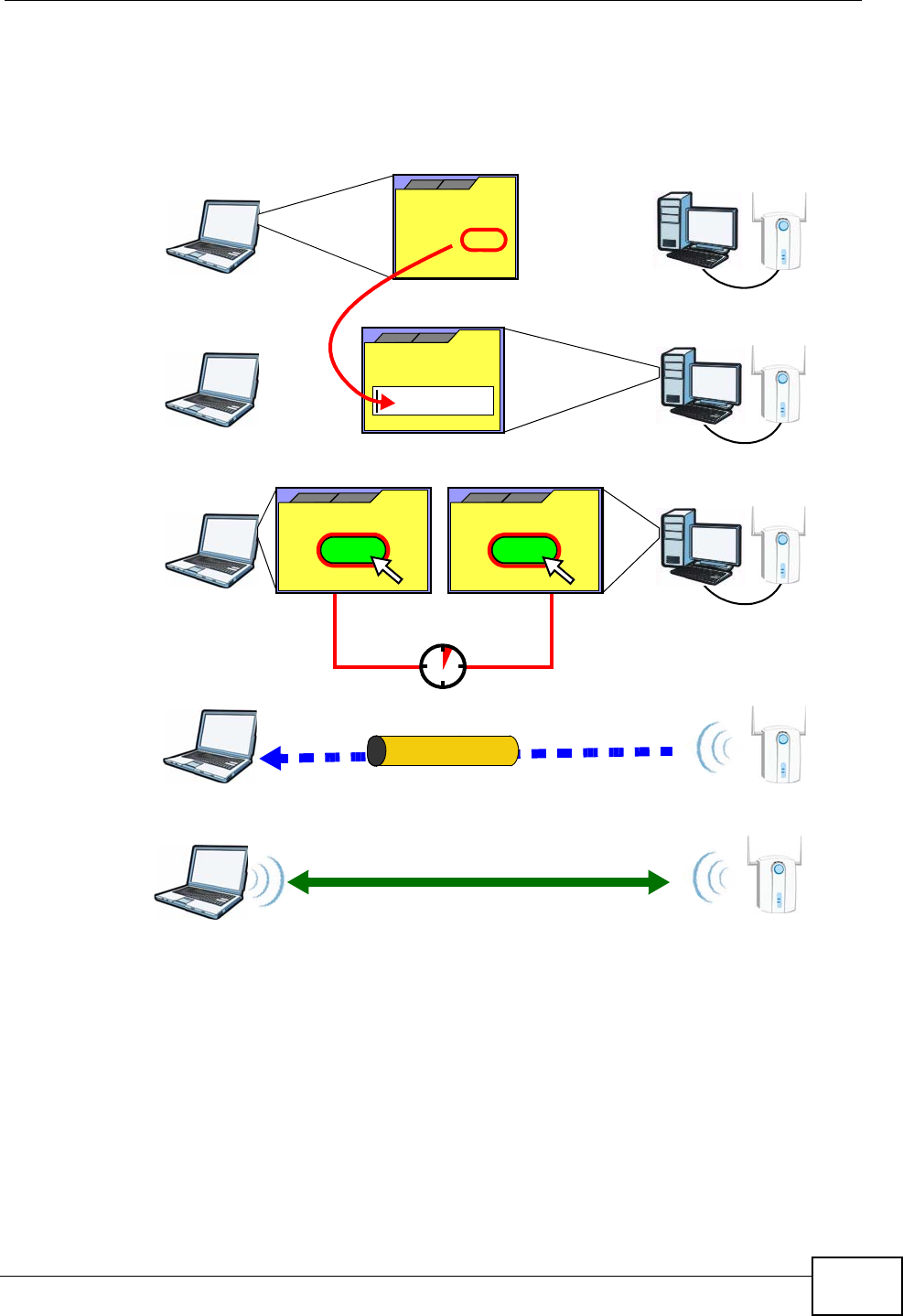
Appendix D Wireless LANs
P-2612HNU(L)-FxF User’s Guide 375
The following figure shows a WPS-enabled wireless client (installed in a notebook
computer) connecting to the WPS-enabled AP via the PIN method.
Figure 199 Example WPS Process: PIN Method
How WPS Works
When two WPS-enabled devices connect, each device must assume a specific role.
One device acts as the registrar (the device that supplies network and security
settings) and the other device acts as the enrollee (the device that receives
network and security settings. The registrar creates a secure EAP (Extensible
Authentication Protocol) tunnel and sends the network name (SSID) and the WPA-
PSK or WPA2-PSK pre-shared key to the enrollee. Whether WPA-PSK or WPA2-PSK
is used depends on the standards supported by the devices. If the registrar is
ENROLLEE
SECURE EAP TUNNEL
SSID
WPA(2)-PSK
WITHIN 2 MINUTES
COMMUNICATION
This device’s
WPS
Enter WPS PIN
WPS
from other device:
WPS PIN: 123456
WPS
START
WPS
START
REGISTRAR
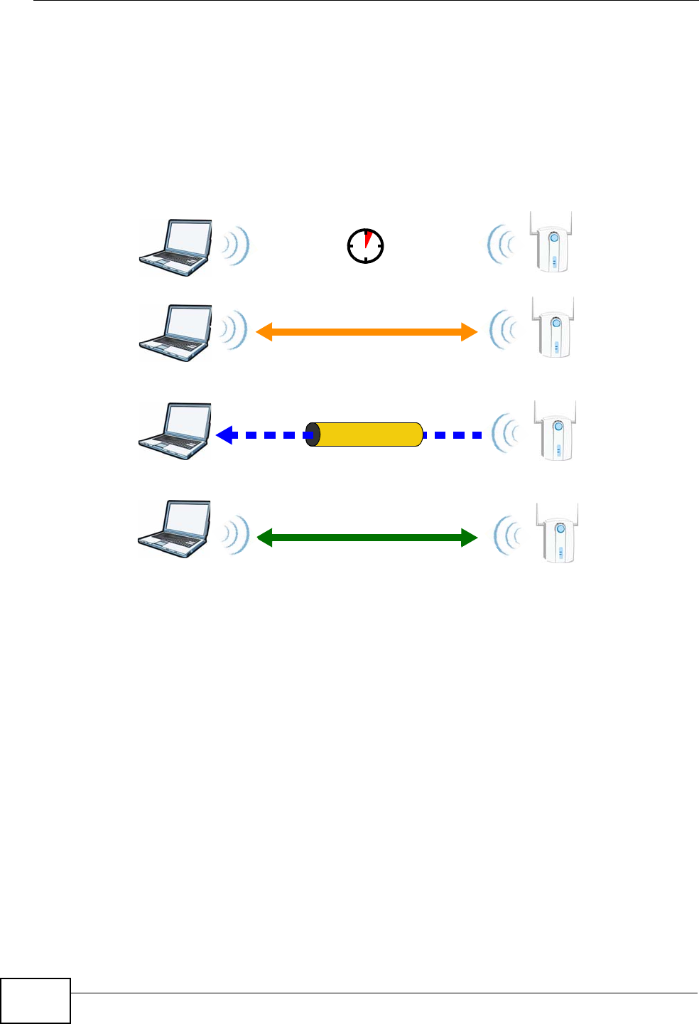
Appendix D Wireless LANs
P-2612HNU(L)-FxF User’s Guide
376
already part of a network, it sends the existing information. If not, it generates
the SSID and WPA(2)-PSK randomly.
The following figure shows a WPS-enabled client (installed in a notebook
computer) connecting to a WPS-enabled access point.
Figure 200 How WPS works
The roles of registrar and enrollee last only as long as the WPS setup process is
active (two minutes). The next time you use WPS, a different device can be the
registrar if necessary.
The WPS connection process is like a handshake; only two devices participate in
each WPS transaction. If you want to add more devices you should repeat the
process with one of the existing networked devices and the new device.
Note that the access point (AP) is not always the registrar, and the wireless client
is not always the enrollee. All WPS-certified APs can be a registrar, and so can
some WPS-enabled wireless clients.
By default, a WPS devices is “unconfigured”. This means that it is not part of an
existing network and can act as either enrollee or registrar (if it supports both
functions). If the registrar is unconfigured, the security settings it transmits to the
enrollee are randomly-generated. Once a WPS-enabled device has connected to
another device using WPS, it becomes “configured”. A configured wireless client
can still act as enrollee or registrar in subsequent WPS connections, but a
configured access point can no longer act as enrollee. It will be the registrar in all
SECURE TUNNEL
SECURITY INFO
WITHIN 2 MINUTES
COMMUNICATION
ACTIVATE
WPS
ACTIVATE
WPS
WPS HANDSHAKE
REGISTRARENROLLEE
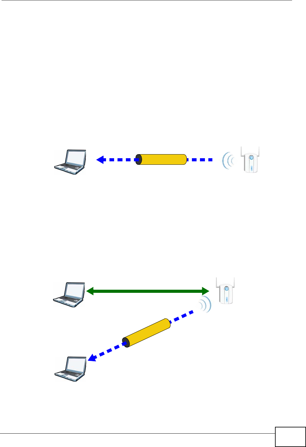
Appendix D Wireless LANs
P-2612HNU(L)-FxF User’s Guide 377
subsequent WPS connections in which it is involved. If you want a configured AP to
act as an enrollee, you must reset it to its factory defaults.
Example WPS Network Setup
This section shows how security settings are distributed in an example WPS setup.
The following figure shows an example network. In step 1, both AP1 and Client 1
are unconfigured. When WPS is activated on both, they perform the handshake. In
this example, AP1 is the registrar, and Client 1 is the enrollee. The registrar
randomly generates the security information to set up the network, since it is
unconfigured and has no existing information.
Figure 201 WPS: Example Network Step 1
In step 2, you add another wireless client to the network. You know that Client 1
supports registrar mode, but it is better to use AP1 for the WPS handshake with
the new client since you must connect to the access point anyway in order to use
the network. In this case, AP1 must be the registrar, since it is configured (it
already has security information for the network). AP1 supplies the existing
security information to Client 2.
Figure 202 WPS: Example Network Step 2
REGISTRARENROLLEE
SECURITY INFO
CLIENT 1 AP1
REGISTRAR
CLIENT 1 AP1
ENROLLEE
CLIENT 2
EXISTING CONNECTION
SECURITYINFO
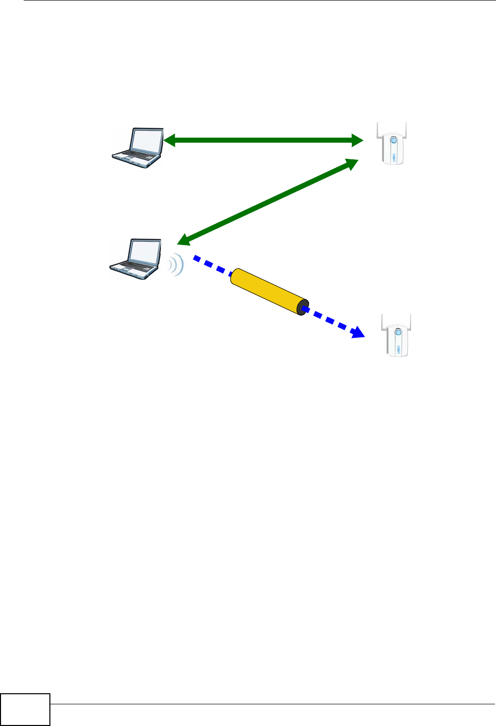
Appendix D Wireless LANs
P-2612HNU(L)-FxF User’s Guide
378
In step 3, you add another access point (AP2) to your network. AP2 is out of
range of AP1, so you cannot use AP1 for the WPS handshake with the new access
point. However, you know that Client 2 supports the registrar function, so you use
it to perform the WPS handshake instead.
Figure 203 WPS: Example Network Step 3
Limitations of WPS
WPS has some limitations of which you should be aware.
• WPS works in Infrastructure networks only (where an AP and a wireless client
communicate). It does not work in Ad-Hoc networks (where there is no AP).
• When you use WPS, it works between two devices only. You cannot enroll
multiple devices simultaneously, you must enroll one after the other.
For instance, if you have two enrollees and one registrar you must set up the
first enrollee (by pressing the WPS button on the registrar and the first enrollee,
for example), then check that it successfully enrolled, then set up the second
device in the same way.
• WPS works only with other WPS-enabled devices. However, you can still add
non-WPS devices to a network you already set up using WPS.
WPS works by automatically issuing a randomly-generated WPA-PSK or WPA2-
PSK pre-shared key from the registrar device to the enrollee devices. Whether
the network uses WPA-PSK or WPA2-PSK depends on the device. You can check
the configuration interface of the registrar device to discover the key the
network is using (if the device supports this feature). Then, you can enter the
key into the non-WPS device and join the network as normal (the non-WPS
device must also support WPA-PSK or WPA2-PSK).
CLIENT 1 AP1
REGISTRAR
CLIENT 2
EXISTING CONNECTION
SECURITYINFO
ENROLLEE
AP1
EXISTINGCONNECTION

Appendix D Wireless LANs
P-2612HNU(L)-FxF User’s Guide 379
• When you use the PBC method, there is a short period (from the moment you
press the button on one device to the moment you press the button on the
other device) when any WPS-enabled device could join the network. This is
because the registrar has no way of identifying the “correct” enrollee, and
cannot differentiate between your enrollee and a rogue device. This is a possible
way for a hacker to gain access to a network.
You can easily check to see if this has happened. WPS works between only two
devices simultaneously, so if another device has enrolled your device will be
unable to enroll, and will not have access to the network. If this happens, open
the access point’s configuration interface and look at the list of associated
clients (usually displayed by MAC address). It does not matter if the access
point is the WPS registrar, the enrollee, or was not involved in the WPS
handshake; a rogue device must still associate with the access point to gain
access to the network. Check the MAC addresses of your wireless clients
(usually printed on a label on the bottom of the device). If there is an unknown
MAC address you can remove it or reset the AP.

Appendix D Wireless LANs
P-2612HNU(L)-FxF User’s Guide
380

P-2612HNU(L)-FxF User’s Guide 381
APPENDIX E
Common Services
The following table lists some commonly-used services and their associated
protocols and port numbers. For a comprehensive list of port numbers, ICMP type/
code numbers and services, visit the IANA (Internet Assigned Number Authority)
web site.
•Name: This is a short, descriptive name for the service. You can use this one or
create a different one, if you like.
•Protocol: This is the type of IP protocol used by the service. If this is TCP/
UDP, then the service uses the same port number with TCP and UDP. If this is
USER-DEFINED, the Port(s) is the IP protocol number, not the port number.
•Port(s): This value depends on the Protocol. Please refer to RFC 1700 for
further information about port numbers.
• If the Protocol is TCP, UDP, or TCP/UDP, this is the IP port number.
• If the Protocol is USER, this is the IP protocol number.
•Description: This is a brief explanation of the applications that use this service
or the situations in which this service is used.
Table 103 Commonly Used Services
NAME PROTOCOL PORT(S) DESCRIPTION
AH
(IPSEC_TUNNEL)
User-Defined 51 The IPSEC AH (Authentication
Header) tunneling protocol uses this
service.
AIM/New-ICQ TCP 5190 AOL’s Internet Messenger service. It
is also used as a listening port by
ICQ.
AUTH TCP 113 Authentication protocol used by some
servers.
BGP TCP 179 Border Gateway Protocol.
BOOTP_CLIENT UDP 68 DHCP Client.
BOOTP_SERVER UDP 67 DHCP Server.
CU-SEEME TCP
UDP
7648
24032
A popular videoconferencing solution
from White Pines Software.
DNS TCP/UDP 53 Domain Name Server, a service that
matches web names (for example
www.zyxel.com) to IP numbers.
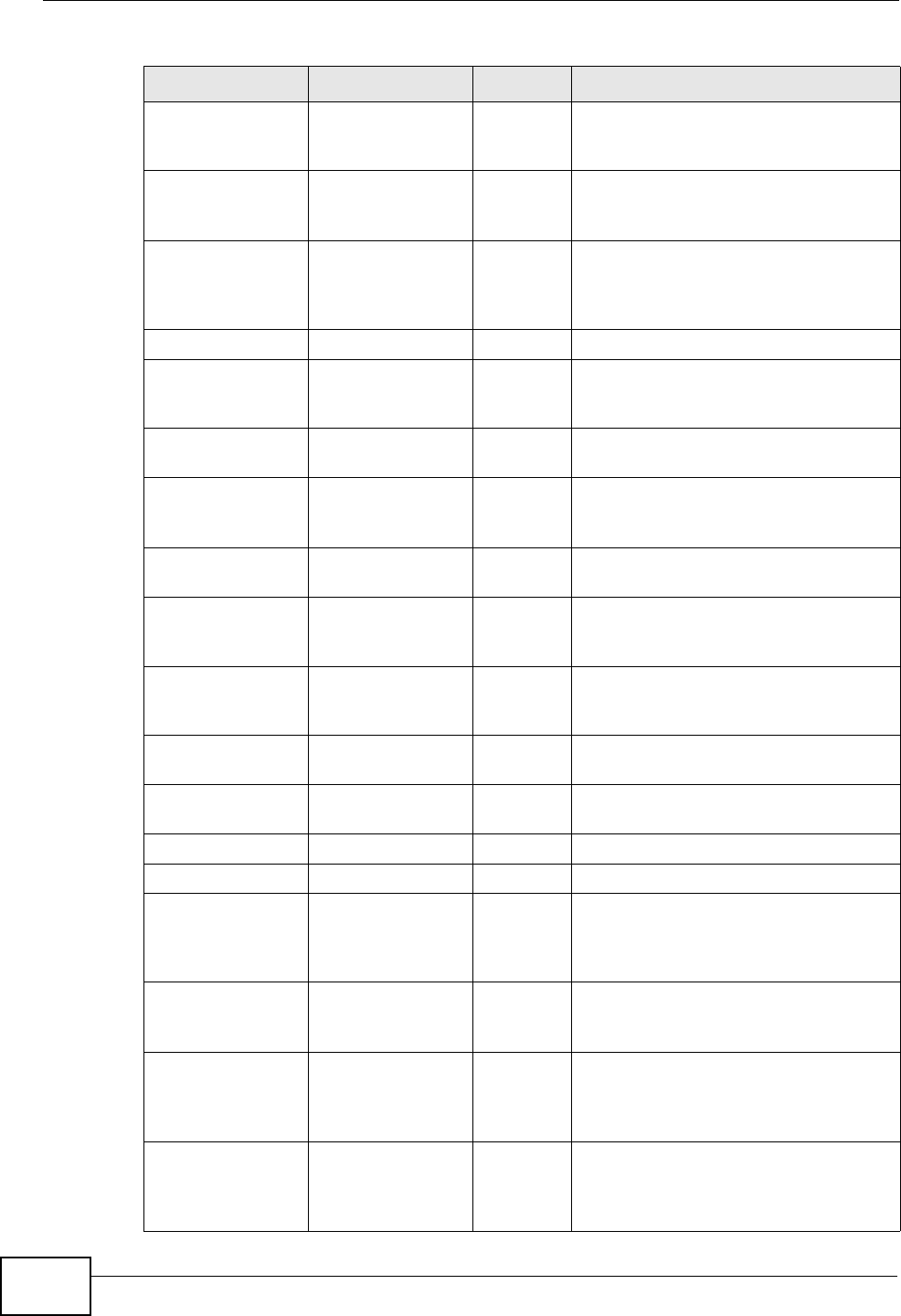
Appendix E Common Services
P-2612HNU(L)-FxF User’s Guide
382
ESP
(IPSEC_TUNNEL)
User-Defined 50 The IPSEC ESP (Encapsulation
Security Protocol) tunneling protocol
uses this service.
FINGER TCP 79 Finger is a UNIX or Internet related
command that can be used to find out
if a user is logged on.
FTP TCP
TCP
20
21
File Transfer Program, a program to
enable fast transfer of files, including
large files that may not be possible by
e-mail.
H.323 TCP 1720 NetMeeting uses this protocol.
HTTP TCP 80 Hyper Text Transfer Protocol - a
client/server protocol for the world
wide web.
HTTPS TCP 443 HTTPS is a secured http session often
used in e-commerce.
ICMP User-Defined 1 Internet Control Message Protocol is
often used for diagnostic or routing
purposes.
ICQ UDP 4000 This is a popular Internet chat
program.
IGMP
(MULTICAST)
User-Defined 2 Internet Group Management Protocol
is used when sending packets to a
specific group of hosts.
IKE UDP 500 The Internet Key Exchange algorithm
is used for key distribution and
management.
IRC TCP/UDP 6667 This is another popular Internet chat
program.
MSN Messenger TCP 1863 Microsoft Networks’ messenger
service uses this protocol.
NEW-ICQ TCP 5190 An Internet chat program.
NEWS TCP 144 A protocol for news groups.
NFS UDP 2049 Network File System - NFS is a client/
server distributed file service that
provides transparent file sharing for
network environments.
NNTP TCP 119 Network News Transport Protocol is
the delivery mechanism for the
USENET newsgroup service.
PING User-Defined 1 Packet INternet Groper is a protocol
that sends out ICMP echo requests to
test whether or not a remote host is
reachable.
POP3 TCP 110 Post Office Protocol version 3 lets a
client computer get e-mail from a
POP3 server through a temporary
connection (TCP/IP or other).
Table 103 Commonly Used Services (continued)
NAME PROTOCOL PORT(S) DESCRIPTION

Appendix E Common Services
P-2612HNU(L)-FxF User’s Guide 383
PPTP TCP 1723 Point-to-Point Tunneling Protocol
enables secure transfer of data over
public networks. This is the control
channel.
PPTP_TUNNEL
(GRE)
User-Defined 47 PPTP (Point-to-Point Tunneling
Protocol) enables secure transfer of
data over public networks. This is the
data channel.
RCMD TCP 512 Remote Command Service.
REAL_AUDIO TCP 7070 A streaming audio service that
enables real time sound over the web.
REXEC TCP 514 Remote Execution Daemon.
RLOGIN TCP 513 Remote Login.
RTELNET TCP 107 Remote Telnet.
RTSP TCP/UDP 554 The Real Time Streaming (media
control) Protocol (RTSP) is a remote
control for multimedia on the
Internet.
SFTP TCP 115 Simple File Transfer Protocol.
SMTP TCP 25 Simple Mail Transfer Protocol is the
message-exchange standard for the
Internet. SMTP enables you to move
messages from one e-mail server to
another.
SNMP TCP/UDP 161 Simple Network Management
Program.
SNMP-TRAPS TCP/UDP 162 Traps for use with the SNMP
(RFC:1215).
SQL-NET TCP 1521 Structured Query Language is an
interface to access data on many
different types of database systems,
including mainframes, midrange
systems, UNIX systems and network
servers.
SSH TCP/UDP 22 Secure Shell Remote Login Program.
STRM WORKS UDP 1558 Stream Works Protocol.
SYSLOG UDP 514 Syslog allows you to send system logs
to a UNIX server.
TACACS UDP 49 Login Host Protocol used for (Terminal
Access Controller Access Control
System).
TELNET TCP 23 Telnet is the login and terminal
emulation protocol common on the
Internet and in UNIX environments. It
operates over TCP/IP networks. Its
primary function is to allow users to
log into remote host systems.
Table 103 Commonly Used Services (continued)
NAME PROTOCOL PORT(S) DESCRIPTION

Appendix E Common Services
P-2612HNU(L)-FxF User’s Guide
384
TFTP UDP 69 Trivial File Transfer Protocol is an
Internet file transfer protocol similar
to FTP, but uses the UDP (User
Datagram Protocol) rather than TCP
(Transmission Control Protocol).
VDOLIVE TCP 7000 Another videoconferencing solution.
Table 103 Commonly Used Services (continued)
NAME PROTOCOL PORT(S) DESCRIPTION

P-2612HNU(L)-FxF User’s Guide 385
APPENDIX F
Legal Information
Copyright
Copyright © 2013 by ZyXEL Communications Corporation.
The contents of this publication may not be reproduced in any part or as a whole,
transcribed, stored in a retrieval system, translated into any language, or
transmitted in any form or by any means, electronic, mechanical, magnetic,
optical, chemical, photocopying, manual, or otherwise, without the prior written
permission of ZyXEL Communications Corporation.
Published by ZyXEL Communications Corporation. All rights reserved.
Disclaimer
ZyXEL does not assume any liability arising out of the application or use of any
products, or software described herein. Neither does it convey any license under
its patent rights nor the patent rights of others. ZyXEL further reserves the right
to make changes in any products described herein without notice. This publication
is subject to change without notice.
Your use of the ZyXEL Device is subject to the terms and conditions of any related
service providers.
Certifications
Federal Communications Commission (FCC) Interference Statement
The device complies with Part 15 of FCC rules. Operation is subject to the
following two conditions:
• This device may not cause harmful interference.
• This device must accept any interference received, including interference that
may cause undesired operations.
This device has been tested and found to comply with the limits for a Class B
digital device pursuant to Part 15 of the FCC Rules. These limits are designed to
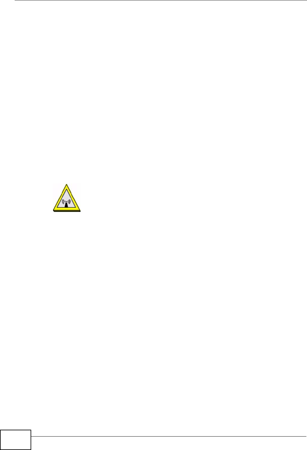
Appendix F Legal Information
P-2612HNU(L)-FxF User’s Guide
386
provide reasonable protection against harmful interference in a residential
installation. This device generates, uses, and can radiate radio frequency energy,
and if not installed and used in accordance with the instructions, may cause
harmful interference to radio communications. However, there is no guarantee
that interference will not occur in a particular installation.
If this device does cause harmful interference to radio/television reception, which
can be determined by turning the device off and on, the user is encouraged to try
to correct the interference by one or more of the following measures:
1Reorient or relocate the receiving antenna.
2Increase the separation between the equipment and the receiver.
3Connect the equipment into an outlet on a circuit different from that to which the
receiver is connected.
4Consult the dealer or an experienced radio/TV technician for help.
FCC Radiation Exposure Statement
• This transmitter must not be co-located or operating in conjunction with any
other antenna or transmitter.
• IEEE 802.11b or 802.11g operation of this product in the U.S.A. is firmware-
limited to channels 1 through 11.
To comply with FCC RF exposure compliance requirements, a separation distance
of at least 20 am must be maintained between the antenna of this device and all
persons.
Notices
Changes or modifications not expressly approved by the party responsible for
compliance could void the user's authority to operate the equipment.
This device has been designed for the WLAN 2.4 GHz network throughout the EC
region and Switzerland, with restrictions in France.

Appendix F Legal Information
P-2612HNU(L)-FxF User’s Guide 387
Ce produit est conçu pour les bandes de fréquences 2,4 GHz conformément à la
législation Européenne. En France métropolitaine, suivant les décisions n°03-908
et 03-909 de l'ARCEP, la puissance d'émission ne devra pas dépasser 10 mW (10
dB) dans le cadre d'une installation WiFi en extérieur pour les fréquences
comprises entre 2454 MHz et 2483,5 MHz.
Viewing Certifications
1Go to http://www.zyxel.com.
2Select your product on the ZyXEL home page to go to that product's page.
3Select the certification you wish to view from this page.
ZyXEL Limited Warranty
ZyXEL warrants to the original end user (purchaser) that this product is free from
any defects in materials or workmanship for a period of up to two years from the
date of purchase. During the warranty period, and upon proof of purchase, should
the product have indications of failure due to faulty workmanship and/or
materials, ZyXEL will, at its discretion, repair or replace the defective products or
components without charge for either parts or labor, and to whatever extent it
shall deem necessary to restore the product or components to proper operating
condition. Any replacement will consist of a new or re-manufactured functionally
equivalent product of equal or higher value, and will be solely at the discretion of
ZyXEL. This warranty shall not apply if the product has been modified, misused,
tampered with, damaged by an act of God, or subjected to abnormal working
conditions.
Note
Repair or replacement, as provided under this warranty, is the exclusive remedy of
the purchaser. This warranty is in lieu of all other warranties, express or implied,
including any implied warranty of merchantability or fitness for a particular use or
purpose. ZyXEL shall in no event be held liable for indirect or consequential
damages of any kind to the purchaser.
To obtain the services of this warranty, contact your vendor. You may also refer to
the warranty policy for the region in which you bought the device at http://
www.zyxel.com/web/support_warranty_info.php.
Registration
Register your product online to receive e-mail notices of firmware upgrades and
information at www.zyxel.com.

Appendix F Legal Information
P-2612HNU(L)-FxF User’s Guide
388

Index
P-2612HNU(L)-FxF User’s Guide 389
Index
A
AAL5 312
ACK message 250
activation
SSID 132
wireless LAN
scheduling 137
adding a printer example 66
administrator password 30
ADSL2 312
Advanced Encryption Standard, see AES
AES 383
ALG 316
alternative subnet mask notation 324
antenna 309
directional 388
gain 387
omni-directional 388
AP (Access Point) 375
Application Layer Gateway 316
applications
Internet access 22
activation 162
iTunes server 161
VoIP 23
Asynchronous Transfer Mode 297
ATM Adaptation Layer 5, see AAL5
audience 3
authentication 138, 140
RADIUS server 140
auto dial 314
automatic logout 30
auto-negotiating rate adaptation 312
B
backup
configuration 291
bandwidth management 187
Basic Service Set, see BSS
blinking LEDs 26
Broadband 93
broadcast 117
BSS 141, 373
example 142
BYE request 250
C
CA 219, 381
call forwarding 315
call hold 254
call park and pickup 314
call return 314
call rule 243
call service mode 253
call transfer 254
call waiting 254, 314
caller ID 315
Canonical Format Indicator See CFI
CBR (Constant Bit Rate) 100, 105, 108
certificate
factory default 223
Certificate Authority, see CA
certificates 219
CA 219
replacing 223
storage space 223
thumbprint algorithms 222
thumbprints 222
trusted CAs 224, 225
verifying fingerprints 221
Certification Authority, see CA
certifications 425
notices 425
viewing 426
CFI 117

Index
P-2612HNU(L)-FxF User’s Guide
390
channel 375
interference 375
channel scan 125
channel, wireless LAN 123
Class of Service 251
Class of Service, see CoS
client list 156
client-server protocol 247
codecs 316
comfort noise generation 228, 315
command interface 25
configuration 164
backup 291
reset 293
restoring 292
copyright 425
CoS 198, 251
country code 314
CTS (Clear to Send) 376
CTS threshold 138
D
data fragment threshold 138
default LAN IP address 29
Denial of Service, see DoS
device management
command interface 25
Telnet 25
DHCP 90, 152, 164, 165, 209
DHCP relay 310
DHCP server 310
diagnostic 295
differentiated services 252
Differentiated Services, see DiffServ
DiffServ (Differentiated Services) 251
code points 251
marking rule 199, 252
disclaimer 425
DLNA 161
DnD 314
DNS 152, 183
DNS server address assignment 117
Do not Disturb, see DnD
domain name system, see DNS
Domain Name System. See DNS.
DS (Differentiated Services) 198
DS field 198, 252
DSCP 198, 251
DSL line, reinitialize 298
DTMF 251
detection and generation 316
Dual-Tone MultiFrequency, see DTMF
dynamic DNS 209
Dynamic Host Configuration Protocol, see DHCP
dynamic jitter buffer 315
dynamic WEP key exchange 382
DYNDNS wildcard 209
E
EAP Authentication 380
echo cancellation 229, 315
Encapsulation 113
MER 113
PPP over Ethernet 113
encapsulation 95
RFC 1483 113
encryption 140, 383
ESS 374
Europe type call service mode 253
Extended Service Set IDentification 124, 133
Extended Service Set, see ESS
external antenna 316
external RADIUS 317
F
F4/F5 OAM 312
File Sharing 159
file sharing 24
filters
MAC address 139
firewalls 211
configuration 213

Index
P-2612HNU(L)-FxF User’s Guide 391
security 215
firmware 289
flash key 253
flashing 253
fragmentation threshold 138, 377
frequency range 317
FTP 202
G
G.168 229, 315
G.711 316
G.729 316
G.992.1 312
G.992.3 312
G.992.5 312
H
hidden node 375
host 265
host name 89
humidity 309
I
IAD 21
IANA 166, 330
IBSS 373
IEEE 802.11g 377
IEEE 802.11g wireless LAN 316
IEEE 802.11i 316
IEEE 802.1Q 116
IEEE 802.1Q VLAN 252
IGMP 117
version 117
IGMP proxy 313
IGMP v1 313
IGMP v2 313
importing trusted CAs 225
Independent Basic Service Set, see IBSS
initialization vector (IV) 383
install UPnP 168
Windows Me 168
Windows XP 170
Integrated Access Device, see IAD
intended audience 3
Internet access 22
Internet Assigned Numbers Authority
See IANA
Internet Assigned Numbers Authority, see IANA
Internet Service Provider, see ISP
IP address 90, 165
default 29
ping 295
WAN 95
IP Address Assignment 116
IP multicasting 313
IP pool 156
IP pool setup 165
ISP 95
iTunes server 161
ITU-T 229
ITU-T G.992.1 298
J
jitter buffer 315
L
LAN 151
and USB printer 163
client list 156
MAC address 157
LAN TCP/IP 165
limitations
wireless LAN 141
WPS 148
listening port 232
Local Area Network, see LAN
login
passwords 30

Index
P-2612HNU(L)-FxF User’s Guide
392
logout 30
automatic 30
logs 257, 261, 277
M
MAC 89, 217
MAC address 157
filter 139
MAC address filtering 217
MAC filter 217
managing the device
command interface 25
good habits 26
Telnet 25
using FTP. See FTP.
Maximum Burst Size (MBS) 100, 105, 109,
114
MBSSID 142
Message Integrity Check, see MIC
MIC 383
model name 89
MTU (Multi-Tenant Unit) 116
multicast 117
multimedia 245
Multiple BSS, see MBSSID
multiple PVC support 311
multiple SIP accounts 315
multiple voice channels 315
multiplexing 114
LLC-based 114
VC-based 114
multiprotocol encapsulation 113
N
NAT 165, 203, 329
definitions 206
how it works 207
what it does 207
Network Address Translation, see NAT
network map 33
non-proxy calls 243
O
OAM 312
OK response 250
operation humidity 309
operation temperature 309
P
Pairwise Master Key (PMK) 383, 385
park 314
passphrase 127
passwords 30
PBC 143
Peak Cell Rate (PCR) 100, 105, 108, 114
peer-to-peer calls 243
Per-Hop Behavior, see PHB
PHB 199, 252
phone book
speed dial 243
phone config 314
pickup 314
PIN, WPS 144
example 145
point-to-point calls 316
ports 26
power adaptor 317
power specifications 309
PPP (Point-to-Point Protocol) Link Layer
Protocol 313
PPP over ATM AAL5 312
PPP over Ethernet 312
PPP over Ethernet, see PPPoE
PPPoE 95, 113, 311
Benefits 113
preamble 138
preamble mode 377
print server 24
Printer Server 163
printer sharing
and LAN 163
configuration 61
requirements 163

Index
P-2612HNU(L)-FxF User’s Guide 393
TCP/IP port 61
product registration 426
profile 45
protocol 95
PSK 383
PSTN call setup signaling 251
pulse dialing 251
Push Button Configuration, see PBC
push button, WPS 143
Q
QoS 187, 188, 198, 251, 315
Quality of Service 315
Quality of Service, see QoS
quick dialing 316
Quick Start Guide 29
R
RADIUS 317, 379
message types 379
messages 379
shared secret key 380
RADIUS server 140
Reach-Extended ADSL 312
Real time Transport Protocol, see RTP
region 314
registration
product 426
reinitialize the ADSL line 298
related documentation 3
REN 315
Request To Send, see RTS
reset 293
RESET button 28
restart 293
restoring configuration 292
RFC 1483 113, 312
RFC 1631 201
RFC 1889 249, 316
RFC 1890 316
RFC 2327 316
RFC 2364 312
RFC 2516 311, 312
RFC 2684 312
RFC 3261 316
Ringer Equivalence Number, see REN
router features 22
RTCP 316
RTP 249, 316
RTS (Request To Send) 376
threshold 375, 376
RTS threshold 138
S
safety warnings 7
scan 125
scheduling
wireless LAN 137
SDP 316
seamless rate adaptation 312
security
wireless LAN 138
security, network 215
service access control 270
Service Set 124, 133
Session Description Protocol 316
Session Initiation Protocol, see SIP
silence suppression 228, 315
SIP 245
account 245
accounts 315
ALG 316
Application Layer Gateway 316
call progression 249
client 247
identities 245
INVITE request 250
number 246
proxy server 247
redirect server 248
register server 249
servers 247
service domain 246

Index
P-2612HNU(L)-FxF User’s Guide
394
URI 245
user agent 247
version 2 316
SMTP error messages 278
SNMP 313
speed dial 243
SRA 312
SSID 139
activation 132
MBSSID 142
stateful inspection 311
static route 179
static VLAN
status 87
status indicators 26
storage humidity 309
storage temperature 309
subnet 321
subnet mask 165, 322
subnetting 324
supplementary services 252
Sustain Cell Rate (SCR) 100, 105, 109
Sustained Cell Rate (SCR) 114
syntax conventions 5
system
firmware 289
passwords 30
status 87
System Info 89
system name 89, 272
T
Tag Control Information See TCI
Tag Protocol Identifier See TPID
TCI
TCP/IP port 61
Telnet 25
temperature 309
Temporal Key Integrity Protocol, see TKIP
The 95
three-way conference 254
thresholds
data fragment 138
RTS/CTS 138
TKIP 383
ToS 251
TPID 116
traffic shaping 114
transparent bridging 313
trusted CAs, and certificates 224
tutorial
VoIP 51
wireless 40
Type of Service, see ToS
U
unicast 117
Uniform Resource Identifier 245
Universal Plug and Play, see UPnP
upgrading firmware 289
UPnP 158
forum 153
security issues 153
USB features 24
USB printer 24
V
VAD 228, 315
version
firmware
version 90
VID
Virtual Circuit (VC) 114
Virtual Local Area Network See VLAN
Virtual Local Area Network, see VLAN
VLAN 116, 252
group 252
ID 252
ID tags 252
Introduction 116
number of possible VIDs
priority frame
static

Index
P-2612HNU(L)-FxF User’s Guide 395
VLAN ID 116
VLAN Identifier See VID
VLAN tag 116
voice activity detection 228, 315
voice channels 315
voice coding 250
VoIP 245
features 23
peer-to-peer calls 243
standards compliance 315
tutorial 51
VoIP features 23
W
WAN
Wide Area Network, see WAN 93
warnings 7
warranty 426
note 426
Web Configurator 29
web configurator
passwords 30
WEP 127, 141, 316
WEP Encryption 128
Wi-Fi Protected Access, see WPA
Wired Equivalent Privacy, see WEP
wireless
client configuration 42
profile 45
security 378
tutorial 40
wireless client WPA supplicants 384
wireless LAN 121
authentication 138, 140
BSS 141
example 142
channel 123
encryption 140
example 122
fragmentation threshold 138
limitations 141
MAC address filter 139, 316
MBSSID 142
preamble 138
RADIUS server 140
RTS/CTS threshold 138
scheduling 137
security 138
SSID 139
activation 132
WEP 141
WPA 141
WPA-PSK 141
WPS 143, 145
example 147
limitations 148
PIN 144
push button 143
wireless network
example 121
wireless security 378
WLAN 121
auto-scan channel 125
interference 375
passphrase 127
scheduling 137
security parameters 386
see also wireless.
WEP 127
WLAN button 25
WPA 141, 316, 382
key caching 384
pre-authentication 384
user authentication 384
vs WPA-PSK 383
wireless client supplicant 384
with RADIUS application example 384
WPA2 382
user authentication 384
vs WPA2-PSK 383
wireless client supplicant 384
with RADIUS application example 384
WPA2-Pre-Shared Key, see WPA2-PSK
WPA2-PSK 382, 383
application example 385
WPA-PSK 141, 383
application example 385
WPS 143, 145
example 147
limitations 148
PIN 144
example 145

Index
P-2612HNU(L)-FxF User’s Guide
396
push button 143