ZyXEL Communications P2612HNUF1F ADSL2+ VoIP IAD User Manual Manual Part 2
ZyXEL Communications Corporation ADSL2+ VoIP IAD Manual Part 2
UserManual.wiki
>
ZyXEL Communications
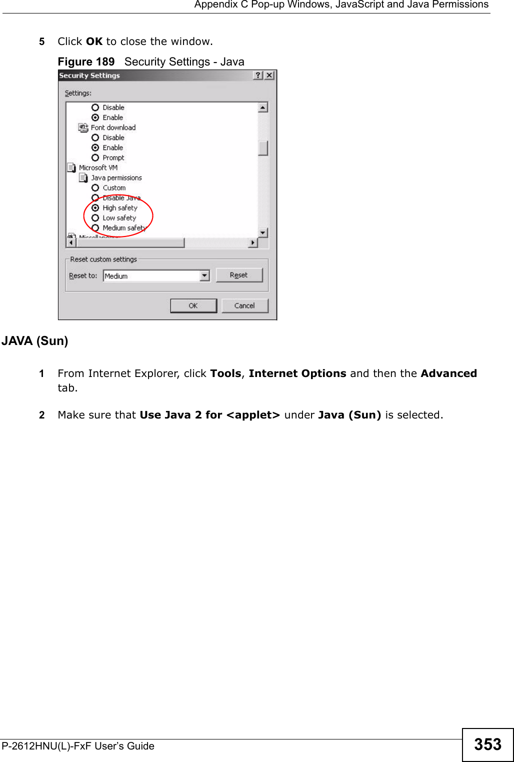
>
P2612HNUF1F User Manual
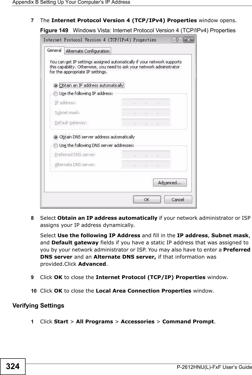
>
Manual Part 2
Contents
1.
Manual
2.
Manual Part 1
3.
Manual Part 2
Manual Part 2
Navigation menu
Upload a User Manual
Namespaces
Wiki Guide
HTML
PDF
Info
Views
User Manual
Discussion / Help
Navigation


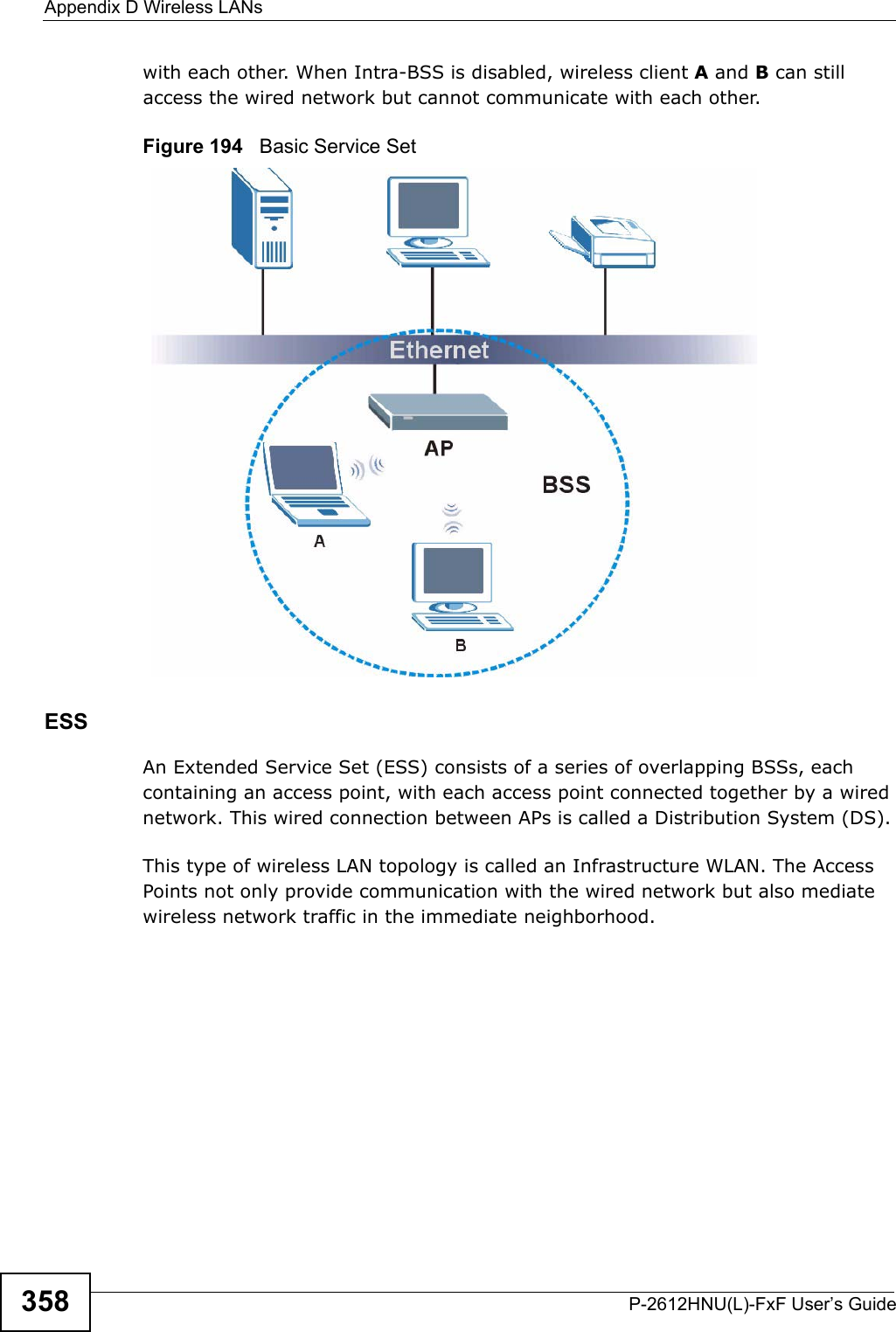
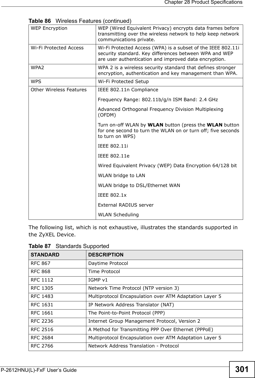
![Chapter 27 TroubleshootingP-2612HNU(L)-FxF User’s Guide 289I cannot see or access the Login screen in the web configurator.1Make sure you are using the correct IP address.• The default IP address is 192.168.1.1.• If you changed the IP address (Section on page 162), use the new IPaddress.• If you changed the IP address and have forgotten it, see the troubleshooting suggestions for I forgot the IP address for the ZyXEL Device.2Check the hardware connections, and make sure the LEDs are behaving as expected. See the Quick Start Guide.3Make sure your Internet browser does not block pop-up windows and has JavaScript and Java enabled. See Appendix C on page 347.4Reset the device to its factory defaults, and try to access the ZyXEL Device withthe default IP address. See Section 1.7 on page 28. 5If the problem continues, contact the network administrator or vendor, or try one of the advanced suggestions.Advanced Suggestions• Try to access the ZyXEL Device using another service, such as Telnet. If you can access the ZyXEL Device, check the remote management settings and firewall rules to find out why the ZyXEL Device does not respond to HTTP. • If your computer is connected to the WAN port or is connected wirelessly, use a computer that is connected to a ETHERNET port.I can see the Login screen, but I cannot log in to the ZyXEL Device.1Make sure you have entered the user name and password correctly. The defaultuser name is admin. These fields are case-sensitive, so make sure [Caps Lock] is not on. 2You cannot log in to the web configurator while someone is using Telnet to accessthe ZyXEL Device. Log out of the ZyXEL Device in the other session, or ask the person who is logged in to log out. 3Turn the ZyXEL Device off and on.](https://usermanual.wiki/ZyXEL-Communications/P2612HNUF1F.Manual-Part-2/User-Guide-1960227-Page-89.png)
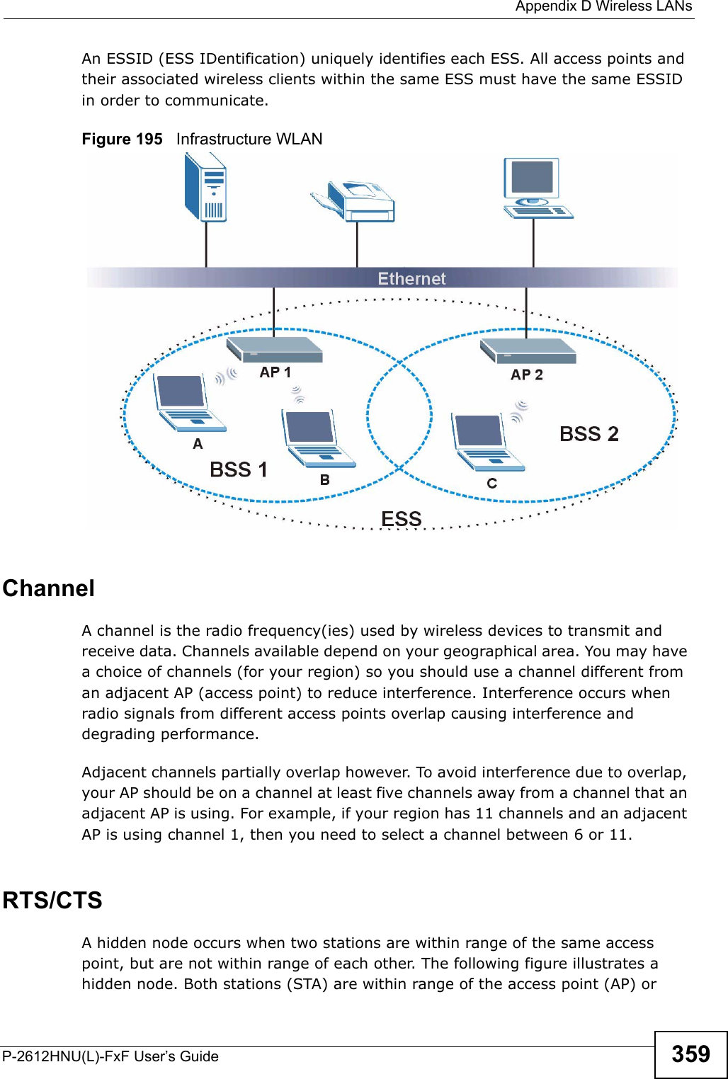
![Chapter 27 TroubleshootingP-2612HNU(L)-FxF User’s Guide2904If this does not work, you have to reset the device to its factory defaults. See Section 27.2 on page 287.I cannot Telnet to the ZyXEL Device. See the troubleshooting suggestions for I cannot see or access the Login screen inthe web configurator. Ignore the suggestions about your browser.I cannot use FTP to upload / download the configuration file. / I cannot use FTP to upload new firmware.See the troubleshooting suggestions for I cannot see or access the Login screen inthe web configurator. Ignore the suggestions about your browser.27.4 Internet AccessI cannot access the Internet.1Check the hardware connections, and make sure the LEDs are behaving as expected. See the Quick Start Guide and Section 1.6 on page 26. 2Make sure you entered your ISP account information correctly. These fields are case-sensitive, so make sure [Caps Lock] is not on. 3If you are trying to access the Internet wirelessly, make sure the wireless settings in the wireless client are the same as the settings in the AP.4If you are trying to access the Internet wirelessly, make sure you have enabledthe wireless LAN by the WPS/WLAN button or the Network Setting > Wireless> General screen.5Disconnect all the cables from your device, and follow the directions in the Quick Start Guide again. 6If the problem continues, contact your ISP.](https://usermanual.wiki/ZyXEL-Communications/P2612HNUF1F.Manual-Part-2/User-Guide-1960227-Page-90.png)
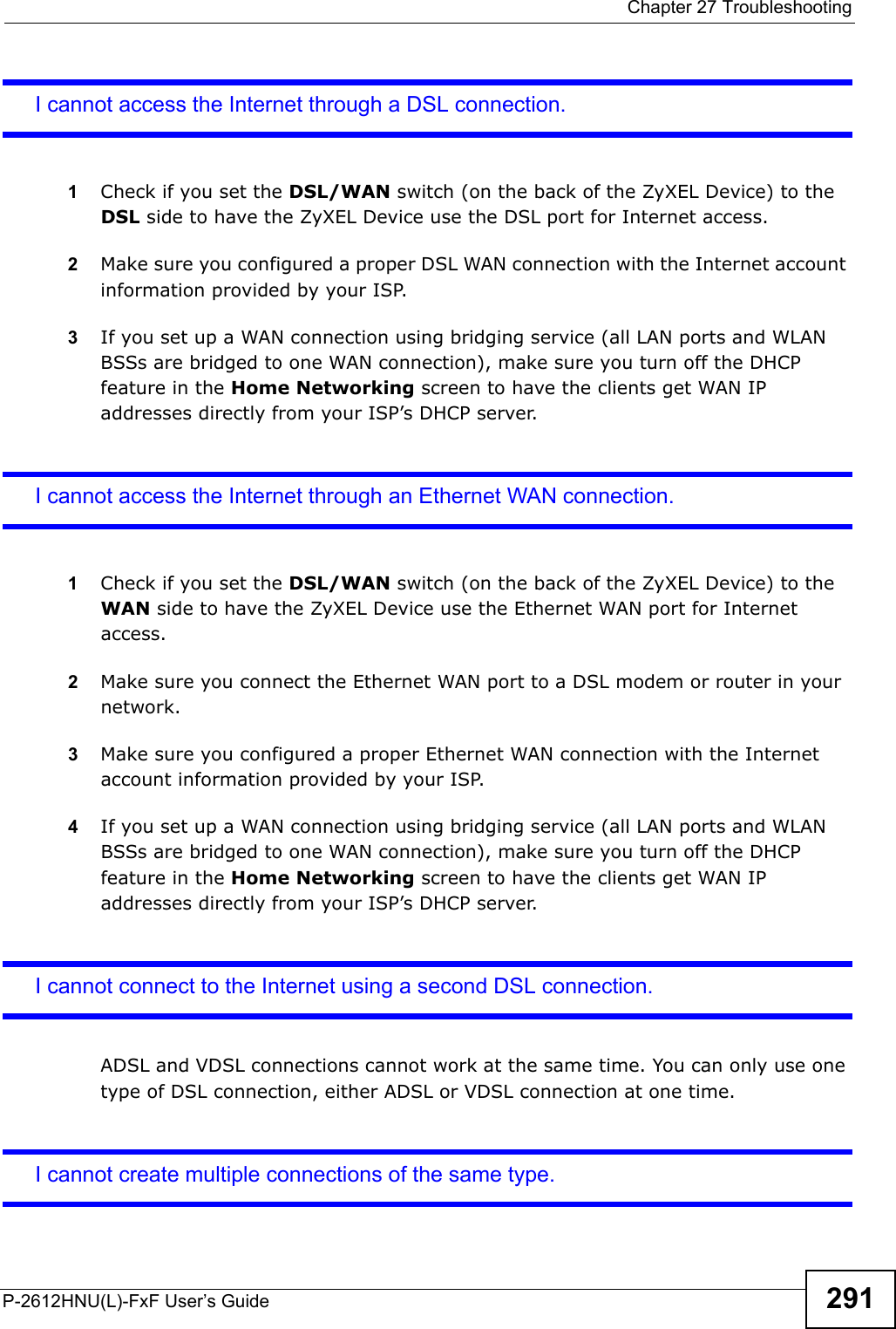
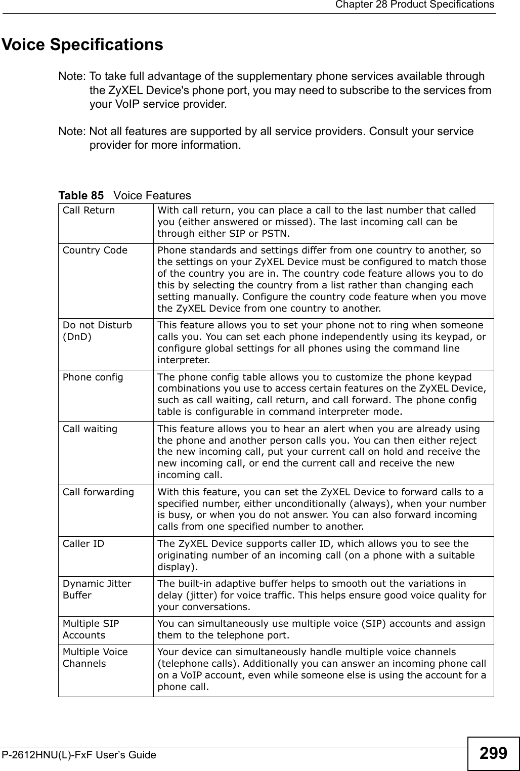


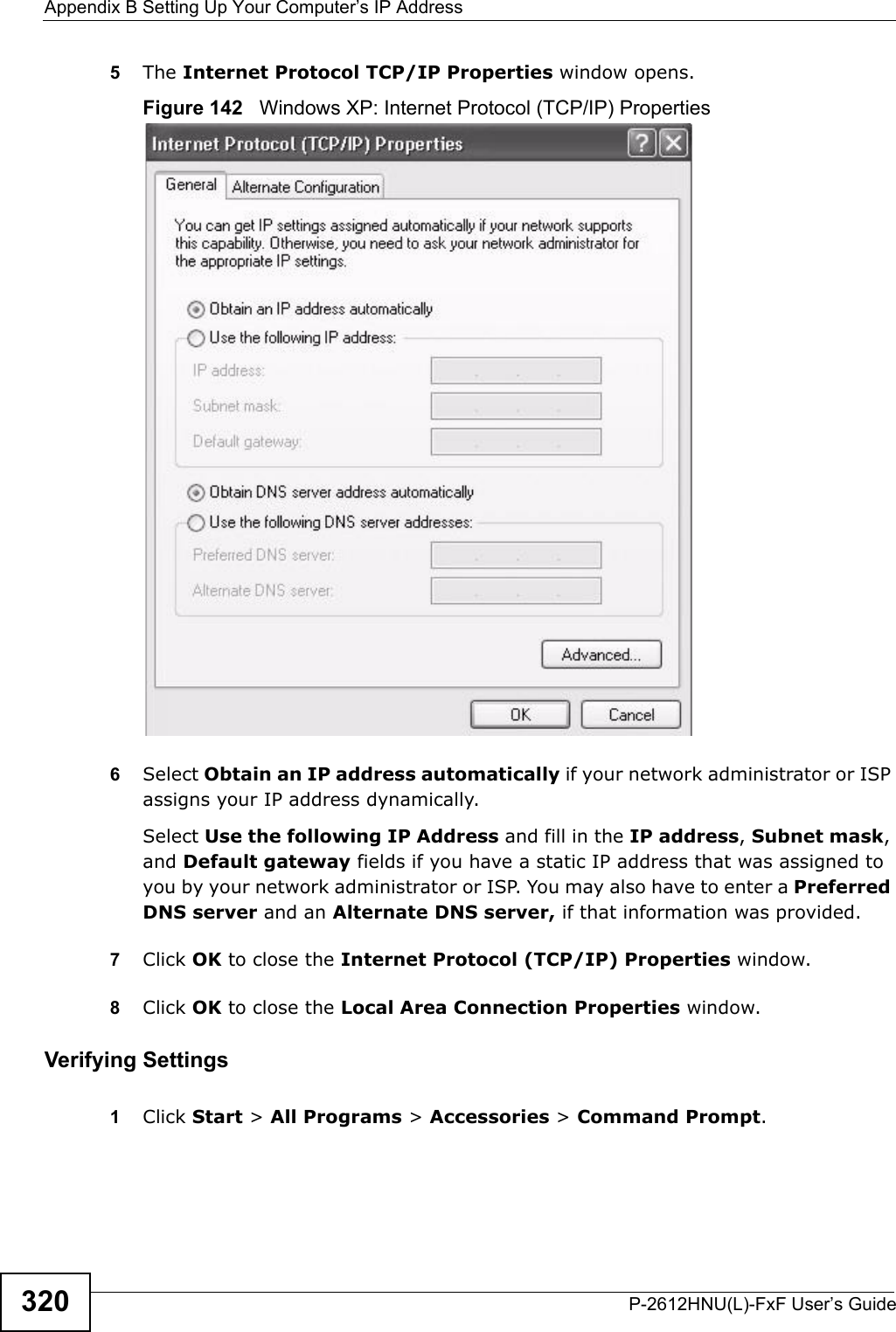
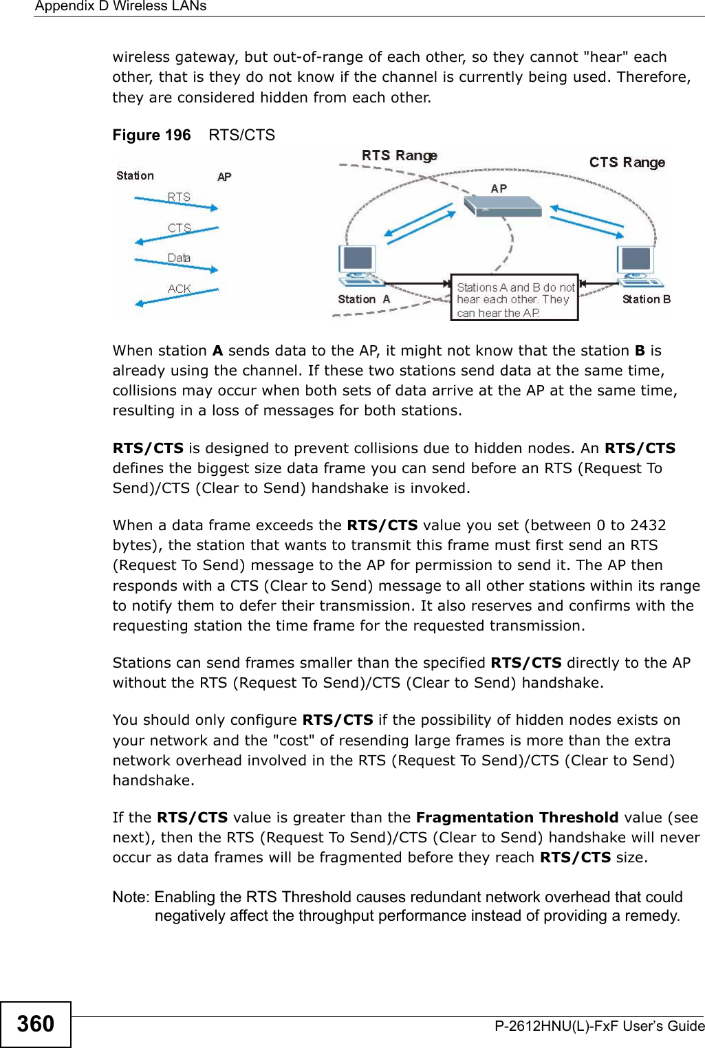
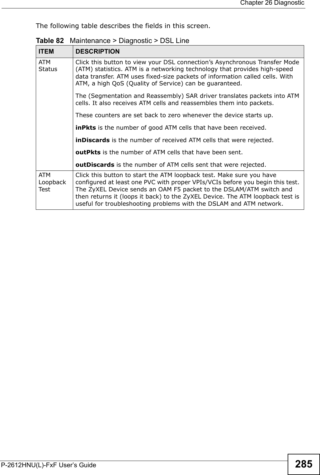
![Appendix B Setting Up Your Computer’s IP AddressP-2612HNU(L)-FxF User’s Guide 3212In the Command Prompt window, type "ipconfig" and then press [ENTER].You can also go to Start > Control Panel > Network Connections, right-click a network connection, click Status and then click the Support tab to view your IP address and connection information.Windows VistaThis section shows screens from Windows Vista Professional.1Click Start > Control Panel.Figure 143 Windows Vista: Start Menu2In the Control Panel, click the Network and Internet icon.Figure 144 Windows Vista: Control Panel](https://usermanual.wiki/ZyXEL-Communications/P2612HNUF1F.Manual-Part-2/User-Guide-1960227-Page-121.png)
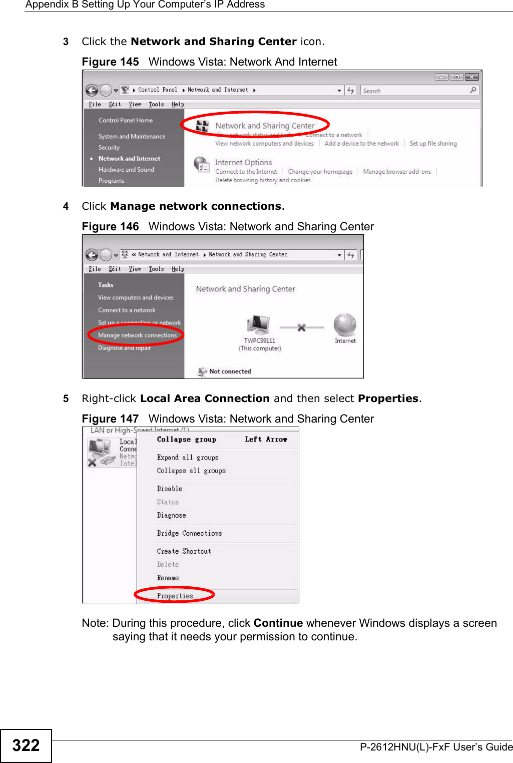
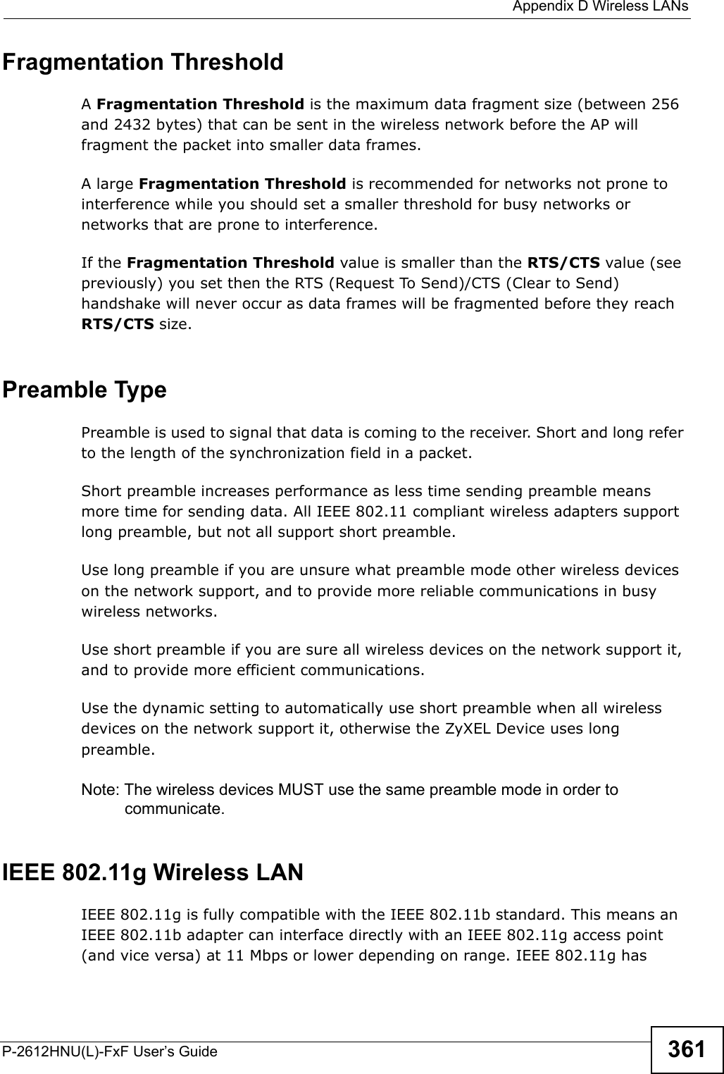
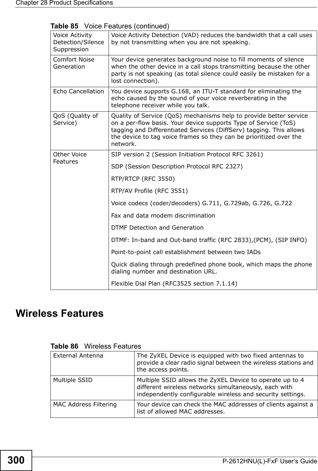
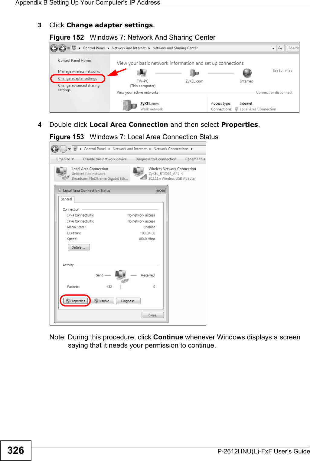
![Appendix B Setting Up Your Computer’s IP AddressP-2612HNU(L)-FxF User’s Guide 3252In the Command Prompt window, type "ipconfig" and then press [ENTER].You can also go to Start > Control Panel > Network Connections, right-click a network connection, click Status and then click the Support tab to view your IP address and connection information.Windows 7This section shows screens from Windows 7 Enterprise.1Click Start > Control Panel.Figure 150 Windows 7: Start Menu2In the Control Panel, click View network status and tasks under the Network and Internet category.Figure 151 Windows 7: Control Panel](https://usermanual.wiki/ZyXEL-Communications/P2612HNUF1F.Manual-Part-2/User-Guide-1960227-Page-125.png)
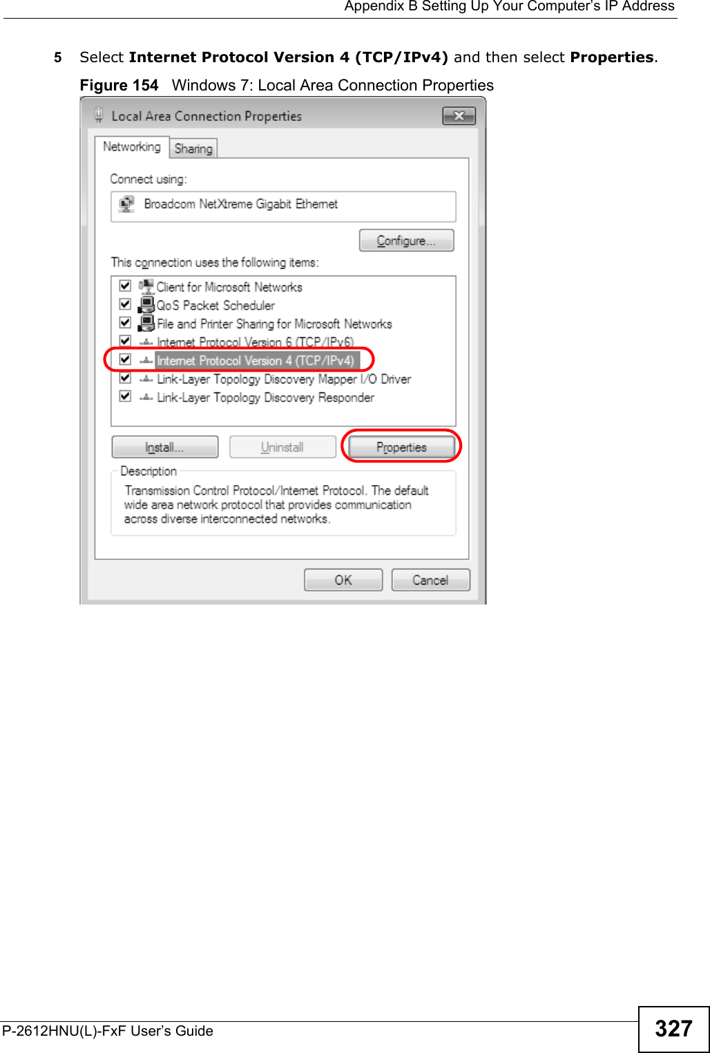
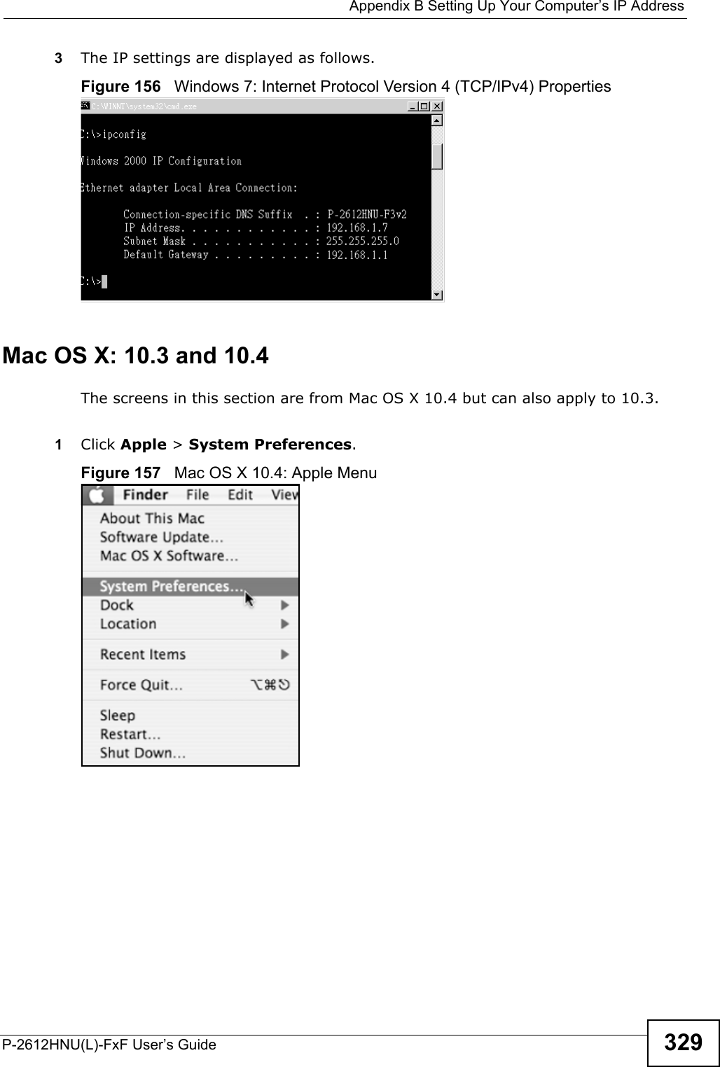
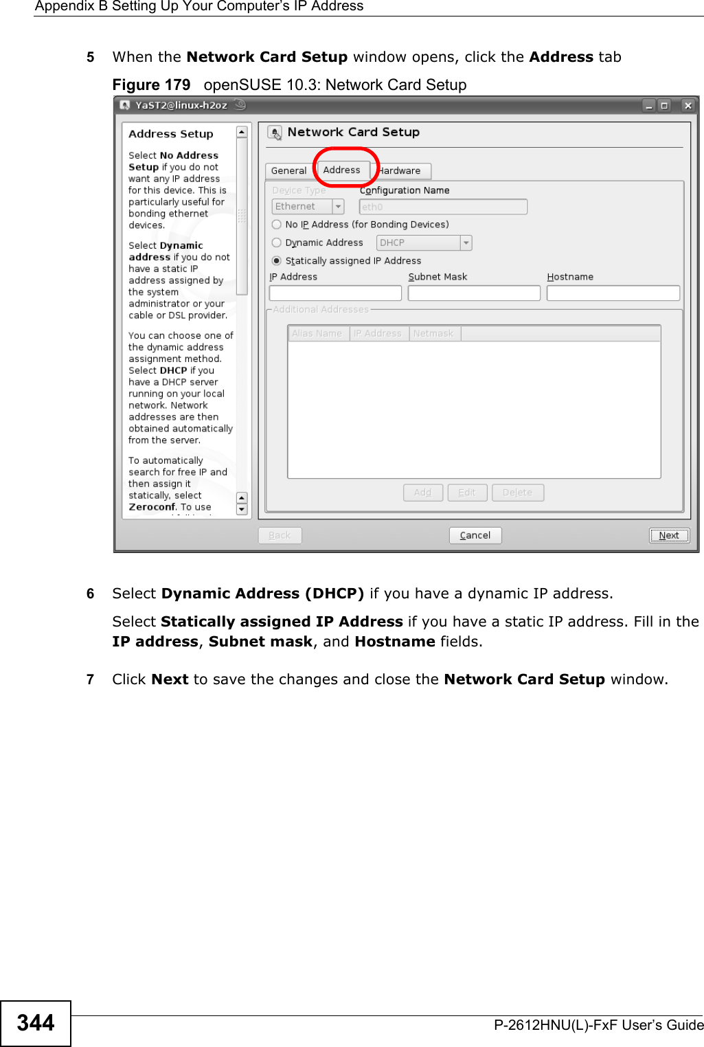
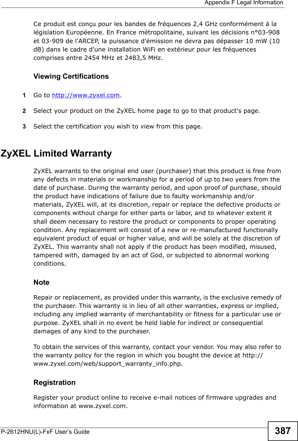
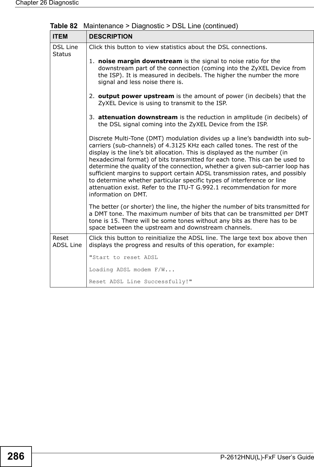
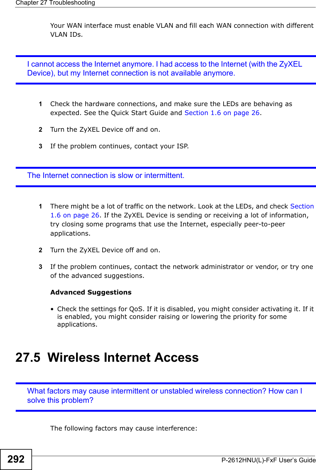
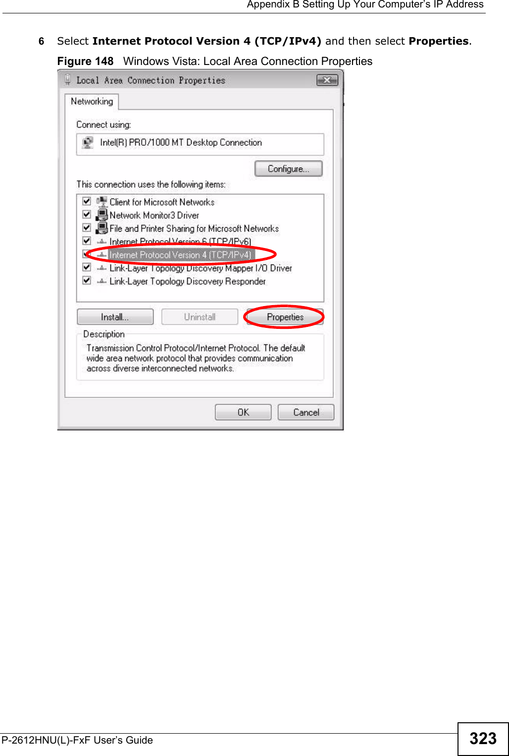
![Appendix B Setting Up Your Computer’s IP AddressP-2612HNU(L)-FxF User’s Guide3286The Internet Protocol Version 4 (TCP/IPv4) Properties window opens.Figure 155 Windows 7: Internet Protocol Version 4 (TCP/IPv4) Properties7Select Obtain an IP address automatically if your network administrator or ISPassigns your IP address dynamically.Select Use the following IP Address and fill in the IP address, Subnet mask, and Default gateway fields if you have a static IP address that was assigned toyou by your network administrator or ISP. You may also have to enter a Preferred DNS server and an Alternate DNS server, if that information was provided. Click Advanced if you want to configure advanced settings for IP, DNS and WINS. 8Click OK to close the Internet Protocol (TCP/IP) Properties window.9Click OK to close the Local Area Connection Properties window.Verifying Settings1Click Start > All Programs > Accessories > Command Prompt.2In the Command Prompt window, type "ipconfig" and then press [ENTER].](https://usermanual.wiki/ZyXEL-Communications/P2612HNUF1F.Manual-Part-2/User-Guide-1960227-Page-128.png)