ZyXEL Communications P320W 802.11g Wireless Firewall Router User Manual ZyBook
ZyXEL Communications Corporation 802.11g Wireless Firewall Router ZyBook
Contents
- 1. Users Manual 1
- 2. Users Manual 2
- 3. Users Manual 3
- 4. Users Manual 4
- 5. Users Manual 5
Users Manual 2
P-320W User’s Guide
Chapter 3 Connection Wizard 51
The following table describes the labels in this screen.
Table 11 Extend(WPA-PSK) Security
LABEL DESCRIPTION
Pre-Shared
Key
Type from 8 to 63 case-sensitive ASCII characters. You can set up the most secure
wireless connection by configuring WPA in the wireless LAN screens. You need to
configure an authentication server to do this.
Back Click Back to display the previous screen.
Next Click Next to proceed to the next screen.
Exit Click Exit to close the wizard screen without saving.
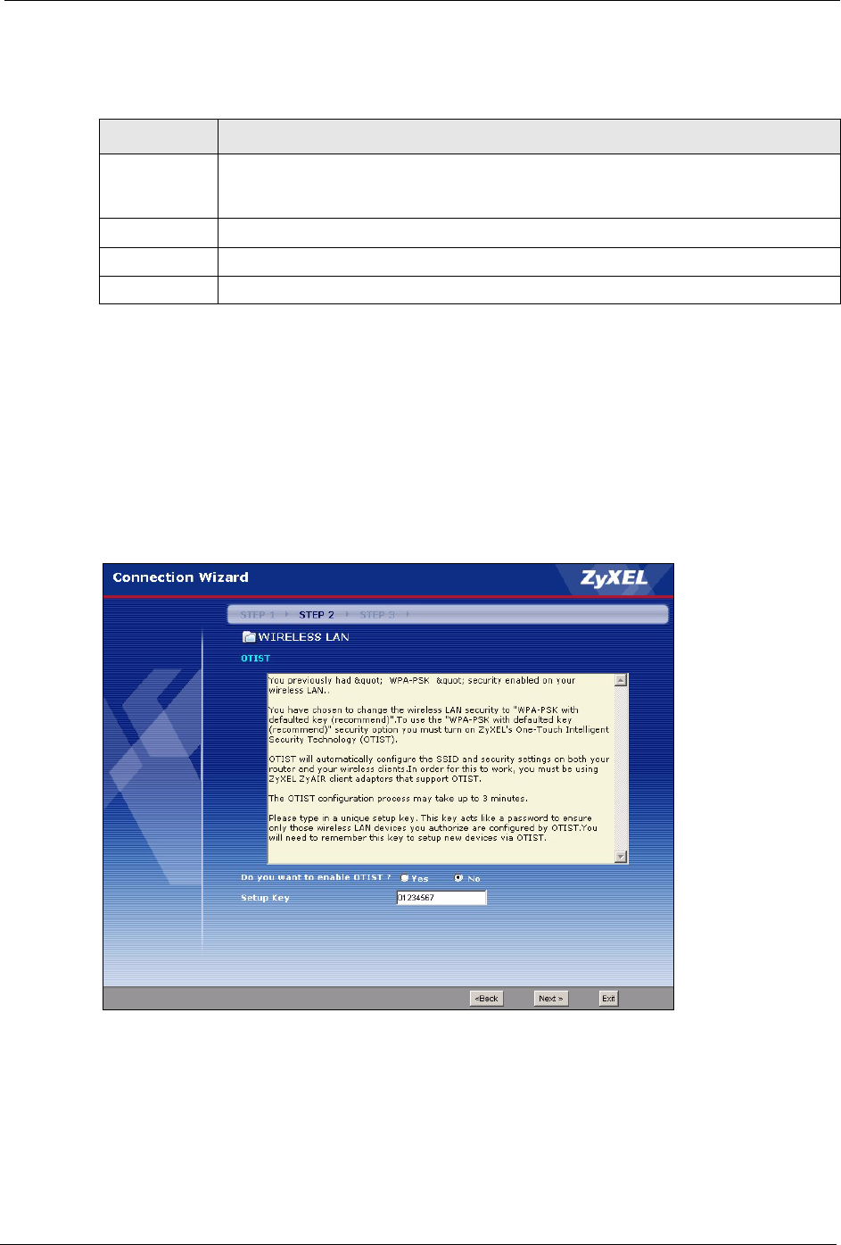
3.3.3 OTIST
The following screen allows you to enable Prestige One-Touch Intelligent Security
Technology (OTIST). One-Touch Intelligent Security Technology (OTIST) allows your
Prestige to assign wireless clients the Prestige’s SSID and static WEP or WPA-PSK
encryption settings. The wireless client must also support OTIST and have OTIST enabled.
See Section 4.5 on page 72 for more information.
Figure 18 OTIST
P-320W User’s Guide
52 Chapter 3 Connection Wizard
The following table describes the labels in this screen.
Table 12 OTIST
LABEL DESCRIPTION
Do you want to
enable OTIST?
Select the Yes radio button and click Next to proceed with the setup wizard and
enable OTIST only when you click Finish in the final wizard screen.
Click No and then Next to proceed to the following screen.
Setup Key The default OTIST Setup Key is “01234567”. This key can be changed in the
web configurator. Be sure to use the same OTIST Setup Key on the Prestige
and wireless clients.
Back Click Back to display the previous screen.
Next Click Next to proceed to the next screen.
Exit Click Exit to close the wizard screen without saving.
Refer to the chapter on wireless LAN for more information.
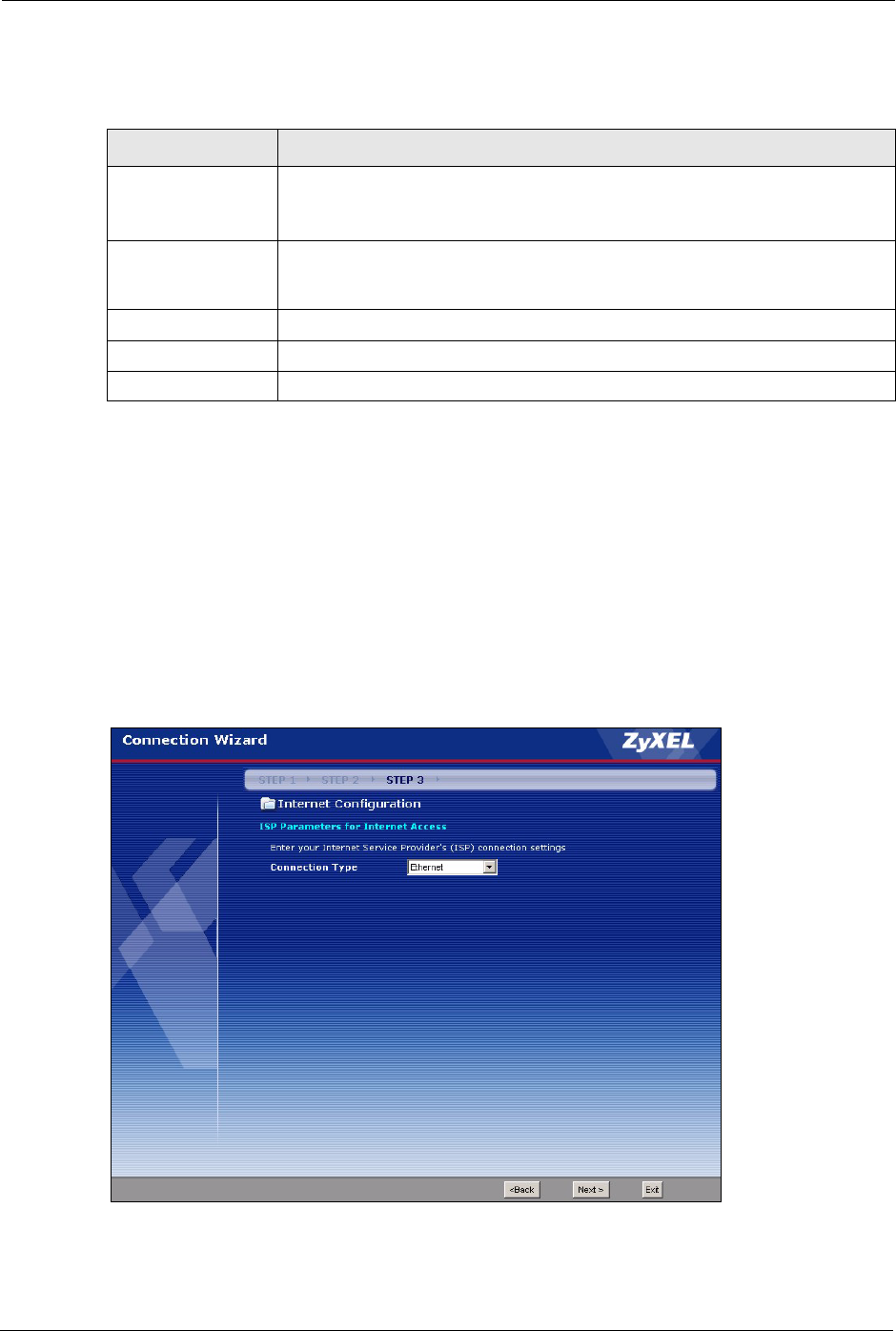
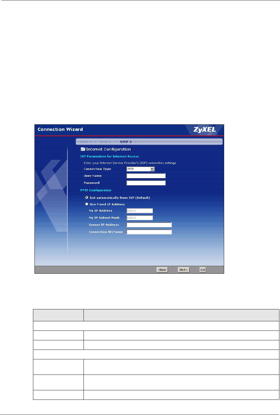
3.4 Connection Wizard: STEP 3: Internet Configuration
The Prestige offers three Internet connection types. They are Ethernet, PPP over Ethernet or
PPTP. The wizard attempts to detect which WAN connection type you are using. If the wizard
does not detect a connection type, you must select one from the drop-down list box. Check
with your ISP to make sure you use the correct type.
Figure 19 Connection Wizard: STEP 3: WAN Connection Type.
P-320W User’s Guide
Chapter 3 Connection Wizard 53
The following table describes the labels in this screen,
Table 13 Connection Wizard: STEP 3: WAN Connection Type
CONNECTION TYPE DESCRIPTION
Ethernet Select the Ethernet option when the WAN port is used as a regular Ethernet.
PPPoE Select the PPP over Ethernet option for a dial-up connection. If your ISP
gave you a an IP address and/or subnet mask, then select PPTP.
PPTP Select the PPTP option for a dial-up connection.
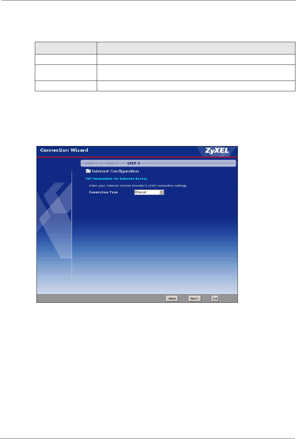
3.4.1 Ethernet Connection Type
Choose Ethernet when the WAN port is used as a regular Ethernet.
Figure 20 Ethernet Connection Type
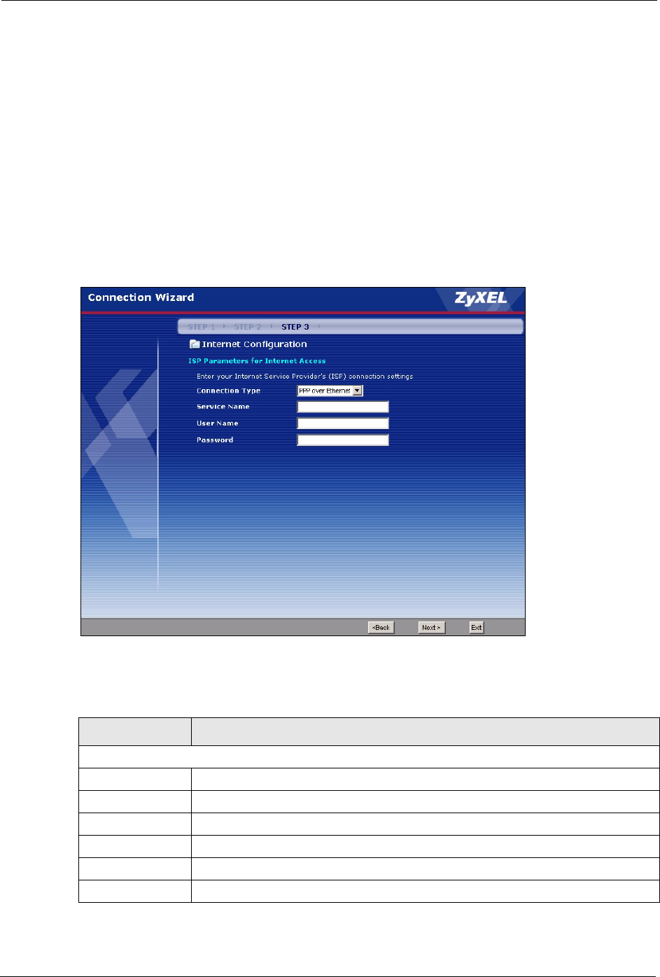
3.4.2 PPPoE Connection Type
Point-to-Point Protocol over Ethernet (PPPoE) functions as a dial-up connection. PPPoE is an
IETF (Internet Engineering Task Force) standard specifying how a host personal computer
interacts with a broadband modem (for example DSL, cable, wireless, etc.) to achieve access
to high-speed data networks.
For the service provider, PPPoE offers an access and authentication method that works with
existing access control systems (for instance, RADIUS).
P-320W User’s Guide
54 Chapter 3 Connection Wizard
One of the benefits of PPPoE is the ability to let end users access one of multiple network
services, a function known as dynamic service selection. This enables the service provider to
easily create and offer new IP services for specific users.
Operationally, PPPoE saves significant effort for both the subscriber and the ISP/carrier, as it
requires no specific configuration of the broadband modem at the subscriber’s site.
By implementing PPPoE directly on the Prestige (rather than individual computers), the
computers on the LAN do not need PPPoE software installed, since the Prestige does that part
of the task. Furthermore, with NAT, all of the LAN's computers will have Internet access.
Refer to the appendix for more information on PPPoE.
Figure 21 PPPoE Connection Type
The following table describes the labels in this screen.
Table 14 PPPoE Connection Type
LABEL DESCRIPTION
ISP Parameter for Internet Access
Service Name Type the name of your service provider.
User Name Type the user name given to you by your ISP.
Password Type the password associated with the user name above.
Next Click Next to continue.
Back Click Back to return to the previous screen.
Exit Click Exit to close the wizard screen without saving.
P-320W User’s Guide
Chapter 3 Connection Wizard 55
3.4.3 PPTP Connection Type
Point-to-Point Tunneling Protocol (PPTP) is a network protocol that enables transfers of data
from a remote client to a private server, creating a Virtual Private Network (VPN) using TCP/
IP-based networks.
PPTP supports on-demand, multi-protocol, and virtual private networking over public
networks, such as the Internet.
Refer to the appendix for more information on PPTP.
Note: The Prestige supports one PPTP server connection at any given time.
Figure 22 PPTP Connection Type
The following table describes the fields in this screen
Table 15 PPTP Connection Type
LABEL DESCRIPTION
ISP Parameters for Internet Access
User Name Type the user name given to you by your ISP.
Password Type the password associated with the User Name above.
PPTP Configuration
Get automatically
from ISP
Select this radio button if your ISP did not assign you a fixed IP address.
Use fixed IP
address
Select this radio button, provided by your ISP to give the Prestige a fixed, unique
IP address.
My IP Address Type the (static) IP address assigned to you by your ISP.
P-320W User’s Guide
56 Chapter 3 Connection Wizard
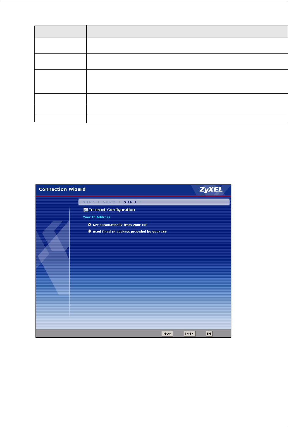
3.4.4 Your IP Address
The following wizard screen allows you to assign a fixed IP address or give the Prestige an
automatically assigned IP address depending on your ISP.
Figure 23 Your IP Address
My IP Subnet
Mask
Type the subnet mask assigned to you by your ISP (if given).
Server IP
Address
Type the IP address of the PPTP server.
Connection ID/
Name
Enter the connection ID or connection name in this field. It must follow the "c:id"
and "n:name" format. For example, C:12 or N:My ISP.
This field is optional and depends on the requirements of your ISP.
Back Click Back to return to the previous screen.
Next Click Next to continue.
Exit Click Exit to close the wizard screen without saving.
Table 15 PPTP Connection Type
LABEL DESCRIPTION

P-320W User’s Guide
Chapter 3 Connection Wizard 57
The following table describes the labels in this screen
Table 16 Your IP Address
LABEL DESCRIPTION
Get automatically from
ISP
Select this option If your ISP did not assign you a fixed IP address. This is
the default selection.
Use fixed IP address
provided by your ISP
Select this option If the ISP assigned a fixed IP address. The fixed IP
address should be in the same subnet as your broadband modem or
router.
Back Click Back to return to the previous screen.
Next Click Next to continue.
Exit Click Exit to close the wizard screen without saving.
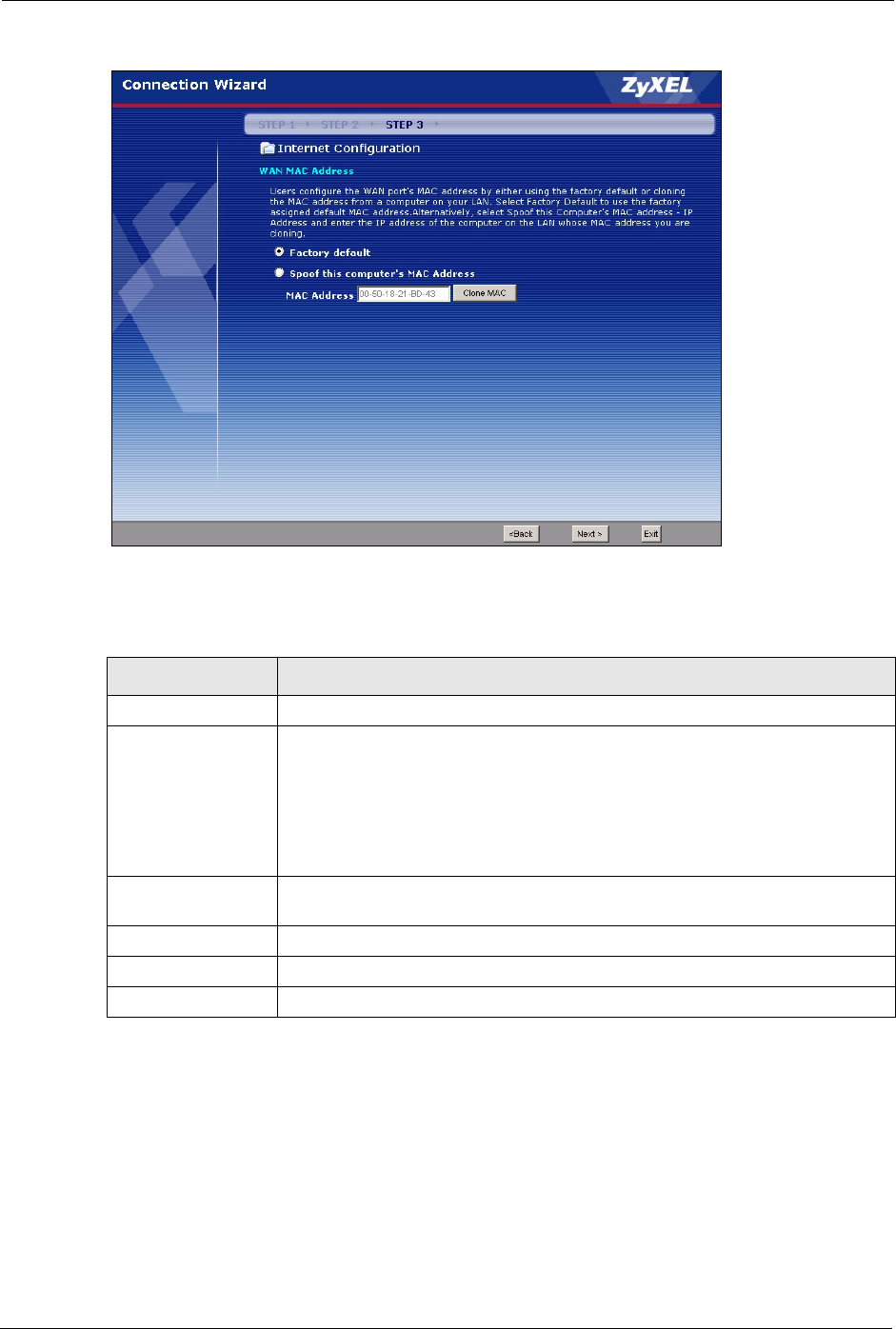
3.4.5 WAN MAC Address
Every Ethernet device has a unique MAC (Media Access Control) address. The MAC address
is assigned at the factory and consists of six pairs of hexadecimal characters, for example, 00-
A0-C5-00-00-02.
You can configure the WAN port's MAC address by either using the factory default or cloning
the MAC address from a computer on your LAN. Once it is successfully configured, the
address will be copied to the "rom" file (ZyNOS configuration file). It will not change unless
you change the setting or upload a different "rom" file.
Table 17 Example of Network Properties for LAN Servers with Fixed IP Addresses
Choose an IP address 192.168.1.2-192.168.1.32; 192.168.1.65-192.168.1.254.
Subnet mask 255.255.255.0
Gateway (or default route) 192.168.1.1(Prestige LAN IP)
This screen allows users to configure the WAN port's MAC address by either using the factory
default or cloning the MAC address from a computer on your LAN.
P-320W User’s Guide
58 Chapter 3 Connection Wizard
Figure 24 WAN MAC Address
The following table describes the fields in this screen.
Table 18 WAN MAC Address
LABEL DESCRIPTION
Factory Default Select Factory Default to use the factory assigned default MAC address.
Spoof this
computer’s MAC
address
Select this option and click Clone MAC to clone the MAC address in the MAC
Address field.
Once it is successfully configured, the address will be copied to the rom file
(ZyNOS configuration file). It will not change unless you change the setting or
upload a different ROM file. It is advisable to clone the MAC address from a
computer on your LAN even if your ISP does not presently require MAC address
authentication.
MAC Address Enter the MAC address of the computer on the LAN whose MAC address you
want to clone.
Back Click Back to return to the previous screen.
Next Click Next to continue.
Exit Click Exit to close the wizard screen without saving.
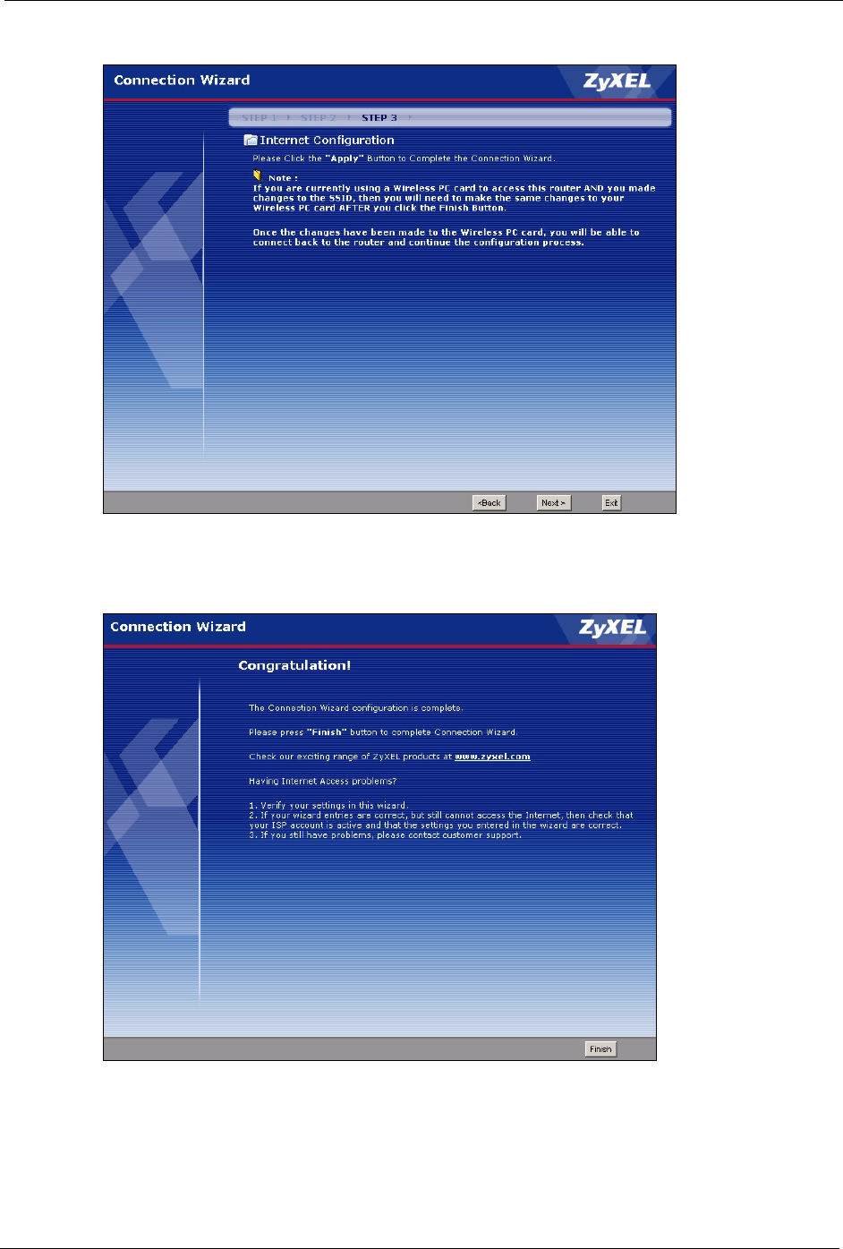
3.4.6 Connection Wizard Complete
Follow the on-screen instructions and click Next.
P-320W User’s Guide
Chapter 3 Connection Wizard 59
Figure 25 Connection Wizard Complete
Click Finish to complete the wizard setup and save your configuration.
Figure 26 Connection Wizard: Congratulation
Well done! You have successfully set up your Prestige to operate on your network and access
the Internet.

P-320W User’s Guide
60 Chapter 3 Connection Wizard

P-320W User’s Guide
Chapter 4 Wireless LAN 61
CHAPTER 4
Wireless LAN
This chapter discusses how to configure Wireless LAN.
4.1 Introduction
A wireless LAN can be as simple as two computers with wireless LAN adapters
communicating in a peer-to-peer network or as complex as a number of computers with
wireless LAN adapters communicating through access points which bridge network traffic to
the wired LAN.
Note: See the WLAN appendix for more detailed information on WLANs.
4.2 Wireless Security Overview
Wireless security is vital to your network to protect wireless communication between wireless
stations, access points and the wired network.
Wireless security methods available on the Prestige are data encryption, wireless client
authentication, restricting access by device MAC address and hiding the Prestige identity.
4.2.1 Encryption
• Use WPA security if you have WPA-aware wireless clients and a RADIUS server. WPA
has user authentication and improved data encryption over WEP.
• Use WPA-PSK if you have WPA-aware wireless clients but no RADIUS server.
• If you don’t have WPA-aware wireless clients, then use WEP key encrypting. A higher
bit key offers better security at a throughput trade-off. You can use Passphrase to
automatically generate 64-bit or 128-bit WEP keys or manually enter 64-bit or 128-bit
WEP keys.
4.2.2 Authentication
WPA has user authentication and you can also configure IEEE 802.1x to use a RADIUS server
to authenticate wireless clients before joining your network.
• Use RADIUS authentication if you have a RADIUS server. See the appendices for
information on protocols used when a client authenticates with a RADIUS server via the
Prestige.

P-320W User’s Guide
62 Chapter 4 Wireless LAN
4.2.3 Restricted Access
The MAC Filter screen allows you to configure the AP to give exclusive access to devices
(Allow) or exclude them from accessing the AP (Deny).
4.2.4 Hide Prestige Identity
If you hide the ESSID, then the Prestige cannot be seen when a wireless client scans for local
APs. The trade-off for the extra security of “hiding” the Prestige may be inconvenient for
some valid WLAN clients.
4.2.5 Using OTIST
In a wireless network, the wireless clients must have the same SSID and security settings as
the access point (AP) or wireless router (we will refer to both as “AP” here) in order to
associate with it. Traditionally this meant that you had to configure the settings on the AP and
then manually configure the exact same settings on each wireless client.
OTIST (One-Touch Intelligent Security Technology) allows you to transfer your AP’s SSID
and WEP or WPA-PSK security settings to wireless clients that support OTIST and are within
transmission range. You can also choose to have OTIST generate a WPA-PSK key for you if
you didn’t configure one manually.
Note: OTIST replaces the pre-configured wireless settings on the wireless clients.
4.3 Configuring Wireless LAN on the Prestige
1Configure the SSID and Security Mode in the Wireless screen. If you configure WEP,
you can’t configure WPA or WPA-PSK.
2Use the MAC Filter screen to restrict access to your wireless network by MAC address.
3If you have OTIST-enabled clients, configure OTIST in the OTIST screen. OTIST
transfers device SSID and WEP or WPA-PSK key settings (if enabled) to wireless
clients.
P-320W User’s Guide
Chapter 4 Wireless LAN 63
The following figure shows the relative effectiveness of these wireless security methods
available on your Prestige.
Table 19 ZyAIR Wireless Security Levels
Security Level Security Type
Least Secure
Most Secure
Unique SSID (Default)
Unique SSID with Hide SSID Enabled
MAC Address Filtering
WEP Encryption
IEEE802.1x EAP with RADIUS Server Authentication
Wi-Fi Protected Access (WPA)
Note: You must enable the same wireless security settings on the Prestige and on all
wireless clients that you want to associate with it.
4.4 General Wireless LAN Screen
Note: If you are configuring the Prestige from a computer connected to the wireless
LAN and you change the Prestige’s SSID or WEP settings, you will lose your
wireless connection when you press Apply to confirm. You must then change
the wireless settings of your computer to match the Prestige’s new settings.
Click the Wireless LAN link under Network to open the General screen.
Figure 27 Wireless: General

P-320W User’s Guide
64 Chapter 4 Wireless LAN
The following table describes the general wireless LAN labels in this screen.
Table 20 Wireless: General
LABEL DESCRIPTION
Enable
Wireless LAN
Click the check box to activate wireless LAN.
Name(SSID) (Service Set IDentity) The SSID identifies the Service Set with which a wireless
station is associated. Wireless stations associating to the access point (AP) must
have the same SSID. Enter a descriptive name (up to 32 printable 7-bit ASCII
characters) for the wireless LAN.
Note: If you are configuring the Prestige from a computer connected
to the wireless LAN and you change the Prestige’s SSID or
WEP settings, you will lose your wireless connection when you
press Apply to confirm. You must then change the wireless
settings of your computer to match the Prestige’s new settings.
Hide SSID Select this check box to hide the SSID in the outgoing beacon frame so a station
cannot obtain the SSID through passive scanning using a site survey tool.
Channel
Selection
Set the operating frequency/channel depending on your particular region.
Select a channel from the drop-down list box.
Refer to the Connection Wizard chapter for more information on channels.
Apply Click Apply to save your changes back to the Prestige.
Reset Click Reset to reload the previous configuration for this screen.
See the rest of this chapter for information on the other labels in this screen.
4.4.1 No Security
Select No Security to allow wireless stations to communicate with the access points without
any data encryption.
Note: If you do not enable any wireless security on your Prestige, your network is
accessible to any wireless networking device that is within range.
P-320W User’s Guide
Chapter 4 Wireless LAN 65
Figure 28 Wireless: No Security
The following table describes the labels in this screen.
Table 21 Wireless No Security
LABEL DESCRIPTION
Security Mode Choose No Security from the drop-down list box.
Apply Click Apply to save your changes back to the Prestige.
Reset Click Reset to reload the previous configuration for this screen.
4.4.2 WEP Encryption
WEP encryption scrambles the data transmitted between the wireless stations and the access
points to keep network communications private. It encrypts unicast and multicast
communications in a network. Both the wireless stations and the access points must use the
same WEP key.
Your Prestige allows you to configure up to four 64-bit or 128-bit WEP keys but only one key
can be enabled at any one time.
In order to configure and enable WEP encryption; click Wireless LAN and Wireless to
display the General screen.
Select Static WEP from the Security Mode list.
P-320W User’s Guide
66 Chapter 4 Wireless LAN
Figure 29 Wireless: Static WEP Encryption
The following table describes the wireless LAN security labels in this screen.
Table 22 Wireless: Static WEP Encryption
LABEL DESCRIPTION
Passphrase Enter a Passphrase (up to 32 printable characters) and clicking Generate. The
Prestige automatically generates four different WEP keys.
Generate After you enter the passphrase, click Generate to have the Prestige generates four
different WEP keys automatically.
Clear Click Clear to discard the passphrase you configured in the Passphrase field and the
WEP key(s) generated automatically or maually configured.
WEP
Encryption
Select 64-bit WEP or 128-bit WEP to enable data encryption.
Authentication
Method
Select Auto, Open System or Shared Key from the drop-down list box.
ASCII Select this option in order to enter ASCII characters as the WEP key.
Hex Select this option in order to enter hexadecimal characters as a WEP key.
The preceding "0x", that identifies a hexadecimal key, is entered automatically.

P-320W User’s Guide
Chapter 4 Wireless LAN 67
4.4.3 Introduction to WPA
Wi-Fi Protected Access (WPA) is a subset of the IEEE 802.11i standard. WPA is preferred to
WEP as WPA has user authentication and improved data encryption. See the appendix for
more information on WPA user authentication and WPA encryption.
If both an AP and the wireless clients support WPA and you have an external RADIUS server,
use WPA for stronger data encryption. If you don't have an external RADIUS server, you
should use WPA-PSK (WPA-Pre-Shared Key) that only requires a single (identical) password
entered into each access point, wireless gateway and wireless client. As long as the passwords
match, a wireless client will be granted access to a WLAN.
4.4.4 WPA-PSK Application Example
A WPA-PSK application looks as follows.
1First enter identical passwords into the AP and all wireless clients. The Pre-Shared Key
(PSK) must consist of between 8 and 63 ASCII characters (including spaces and
symbols).
2The AP checks each wireless client's password and (only) allows it to join the network if
the password matches.
3The AP derives and distributes keys to the wireless clients.
4The AP and wireless clients use the TKIP encryption process to encrypt data exchanged
between them.
Key 1 to Key 4 The WEP keys are used to encrypt data. Both the Prestige and the wireless stations
must use the same WEP key for data transmission.
If you chose 64-bit WEP, then enter any 5 ASCII characters or 10 hexadecimal
characters ("0-9", "A-F").
If you chose 128-bit WEP, then enter 13 ASCII characters or 26 hexadecimal
characters ("0-9", "A-F").
You must configure at least one key, only one key can be activated at any one time.
The default key is key 1.
Apply Click Apply to save your changes back to the Prestige.
Reset Click Reset to reload the previous configuration for this screen.
Table 22 Wireless: Static WEP Encryption
LABEL DESCRIPTION
P-320W User’s Guide
68 Chapter 4 Wireless LAN
Figure 30 WPA-PSK Authentication
4.4.5 WPA-PSK Authentication Screen
In order to configure and enable WPA-PSK Authentication; click the Wireless LAN link
under Network to display the General screen. Select WPA-PSK from the Security Mode
list.
Figure 31 Wireless: WPA-PSK
The following table describes the labels in this screen.
Table 23 Wireless: WPA-PSK
LABEL DESCRIPTION
Pre-Shared Key The encryption mechanisms used for WPA and WPA-PSK are the same. The only
difference between the two is that WPA-PSK uses a simple common password,
instead of user-specific credentials.
Type a pre-shared key from 8 to 63 case-sensitive ASCII characters (including
spaces and symbols).
Apply Click Apply to save your changes back to the Prestige.
Reset Click Reset to reload the previous configuration for this screen.
P-320W User’s Guide
Chapter 4 Wireless LAN 69
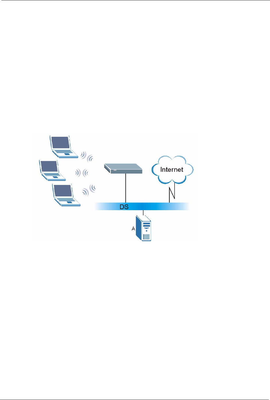
4.4.6 WPA with RADIUS Application Example
You need the IP address of the RADIUS server, its port number (default is 1812), and the
RADIUS shared secret. A WPA application example with an external RADIUS server looks
as follows. "A" is the RADIUS server. "DS" is the distribution system.
1The AP passes the wireless client's authentication request to the RADIUS server.
2The RADIUS server then checks the user's identification against its database and grants
or denies network access accordingly.
3The RADIUS server distributes a Pairwise Master Key (PMK) key to the AP that then
sets up a key hierarchy and management system, using the pair-wise key to dynamically
generate unique data encryption keys to encrypt every data packet that is wirelessly
communicated between the AP and the wireless clients.
Figure 32 WPA with RADIUS Application Example
4.4.7 Wireless Client WPA Supplicants
A wireless client supplicant is the software that runs on an operating system instructing the
wireless client how to use WPA. At the time of writing, the most widely available supplicant is
the WPA patch for Windows XP, Funk Software's Odyssey client.
The Windows XP patch is a free download that adds WPA capability to Windows XP's built-
in "Zero Configuration" wireless client. However, you must run Windows XP to use it.
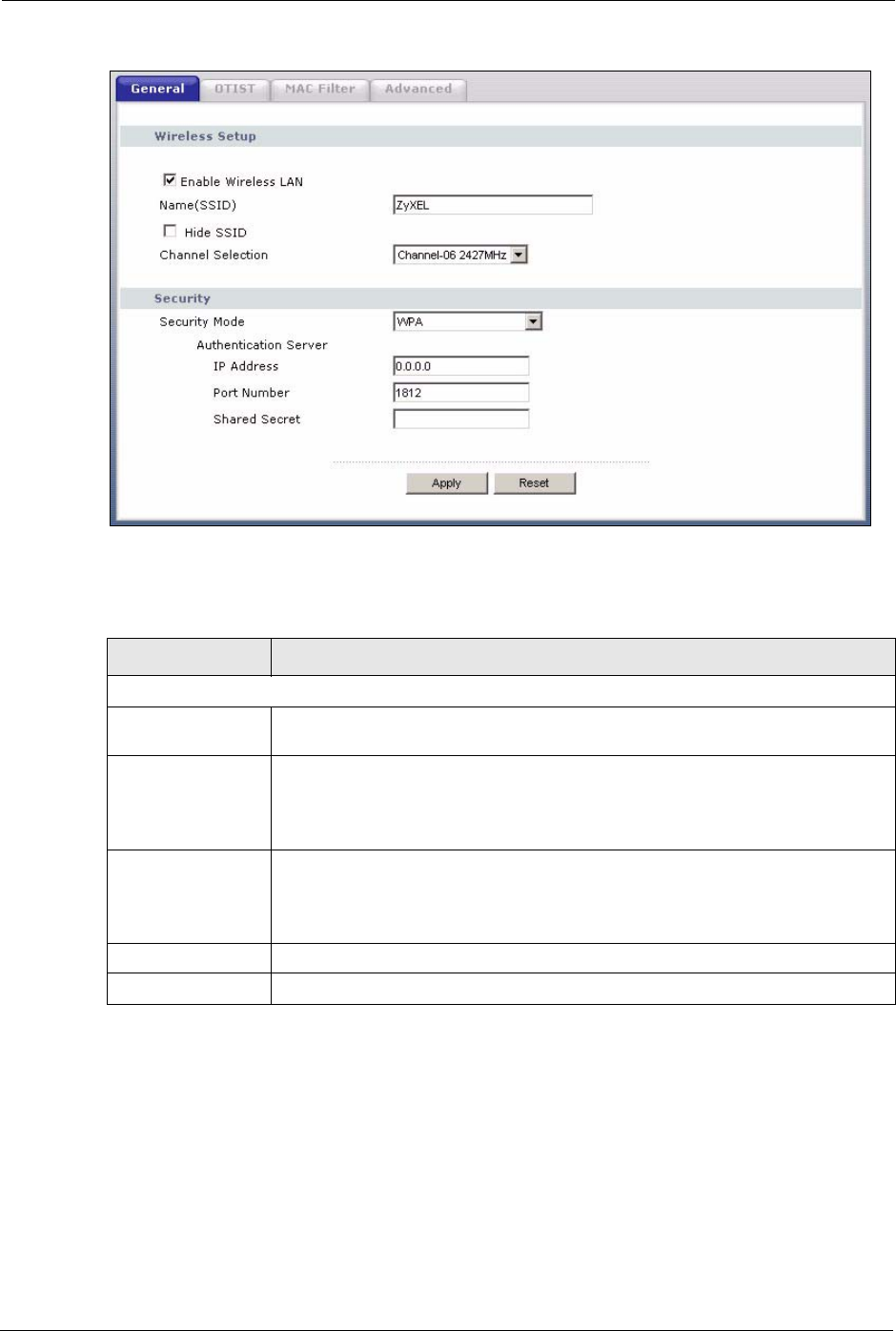
4.4.8 WPA Authentication Screen
In order to configure and enable WPA Authentication; click the Wireless LAN link under
Network to display the General screen. Select WPA from the Security Mode list.
P-320W User’s Guide
70 Chapter 4 Wireless LAN
Figure 33 Wireless: WPA
The following table describes the labels in this screen.
Table 24 Wireless: WPA
LABEL DESCRIPTION
Authentication Server
IP Address Enter the IP address of the external authentication server in dotted decimal
notation.
Port Number Enter the port number of the external authentication server. The default port
number is 1812.
You need not change this value unless your network administrator instructs you
to do so with additional information.
Shared Secret Enter a password (up to 31 alphanumeric characters) as the key to be shared
between the external authentication server and the Prestige.
The key must be the same on the external authentication server and your
Prestige. The key is not sent over the network.
Apply Click Apply to save your changes back to the Prestige.
Reset Click Reset to reload the previous configuration for this screen.
4.4.9 IEEE 802.1x Overview
You need the following for IEEE 802.1x authentication.
• A computer with an IEEE 802.11 a/b/g wireless LAN adapter and equipped with a web
browser (with JavaScript enabled) and/or Telnet.
P-320W User’s Guide
Chapter 4 Wireless LAN 71
• A wireless station computer must be running IEEE 802.1x-compliant software. Not all
Windows operating systems support IEEE 802.1x (see the Microsoft web site for details).
For other operating systems, see their documentation. If your operating system does not
support IEEE 802.1x, then you may need to install IEEE 802.1x client software.
• An optional network RADIUS server for remote user authentication and accounting.
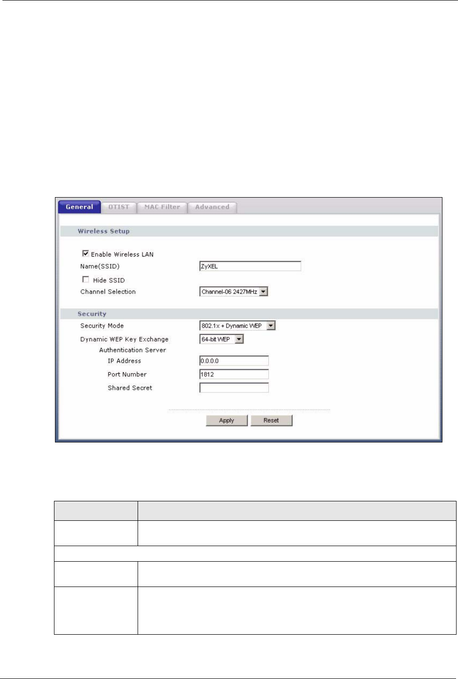
4.4.10 IEEE 802.1x and Dynamic WEP Key Exchange Screen
In order to configure and enable 802.1x and dynamic WEP key exchange; click the Wireless
LAN link under Network to display the General screen. Select 802.1x + Dynamic WEP
from the Security Mode list.
Figure 34 Wireless: 802.1x and Dynamic WEP
The following table describes the labels in this screen.
Table 25 Wireless: 802.1x and Dynamic WEP
LABEL DESCRIPTION
Dynamic WEP Key
Exchange
Select 64-bit WEP or 128-bit WEP to enable data encryption. Up to 32 stations
can access the Prestige when you configure dynamic WEP key exchange.
Authentication Server
IP Address Enter the IP address of the external authentication server in dotted decimal
notation.
Port Number Enter the port number of the external authentication server. The default port
number is 1812.
You need not change this value unless your network administrator instructs you
to do so with additional information.

P-320W User’s Guide
72 Chapter 4 Wireless LAN
4.5 OTIST
OTIST (One-Touch Intelligent Security Technology) allows your Prestige to set the wireless
client to use the same wireless settings as the Prestige.
Note: The wireless client must support OTIST and have OTIST enabled.
The following are the wireless settings that the Prestige assigns to the wireless client if OTIST
is enabled on both devices and the OTIST setup keys are the same.
•SSID
• Security (WEP or WPA-PSK)
Note: This will replace the pre-configured wireless settings on the wireless clients.
4.5.1 Enabling OTIST
You must enable OTIST on both the AP and wireless client before you start transferring
settings.
Note: The AP and wireless client(s) MUST use the same Setup key.
4.5.1.1 AP
You can enable OTIST using the Reset button or the web configurator.
4.5.1.1.1 Reset button
If you use the Reset button, the default (01234567) or previous saved (through the web
configurator) Setup key is used to encrypt the settings that you want to transfer.
Hold in the Reset button for one or two seconds.
Note: If you hold in the Reset button too long, the device will reset to the factory
defaults!
Shared Secret Enter a password (up to 31 alphanumeric characters) as the key to be shared
between the external authentication server and the Prestige.
The key must be the same on the external authentication server and your
Prestige. The key is not sent over the network.
Apply Click Apply to save your changes back to the Prestige.
Reset Click Reset to reload the previous configuration for this screen.
Table 25 Wireless: 802.1x and Dynamic WEP
LABEL DESCRIPTION
P-320W User’s Guide
Chapter 4 Wireless LAN 73
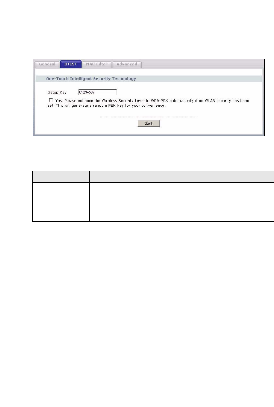
4.5.1.1.2 Web Configurator
Click the Wireless LAN link under Network and then the OTIST tab. The following screen
displays.
Figure 35 Wireless: OTIST
The following table describes the labels in this screen.
Table 26 Wireless: OTIST
LABEL DESCRIPTION
Setup Key Type an OTIST Setup Key of exactly eight ASCII characters in length.
The default OTIST setup key is "01234567".
Note: If you change the OTIST setup key here, you must also
make the same change on the wireless client(s).
P-320W User’s Guide
74 Chapter 4 Wireless LAN
4.5.1.2 Wireless Client
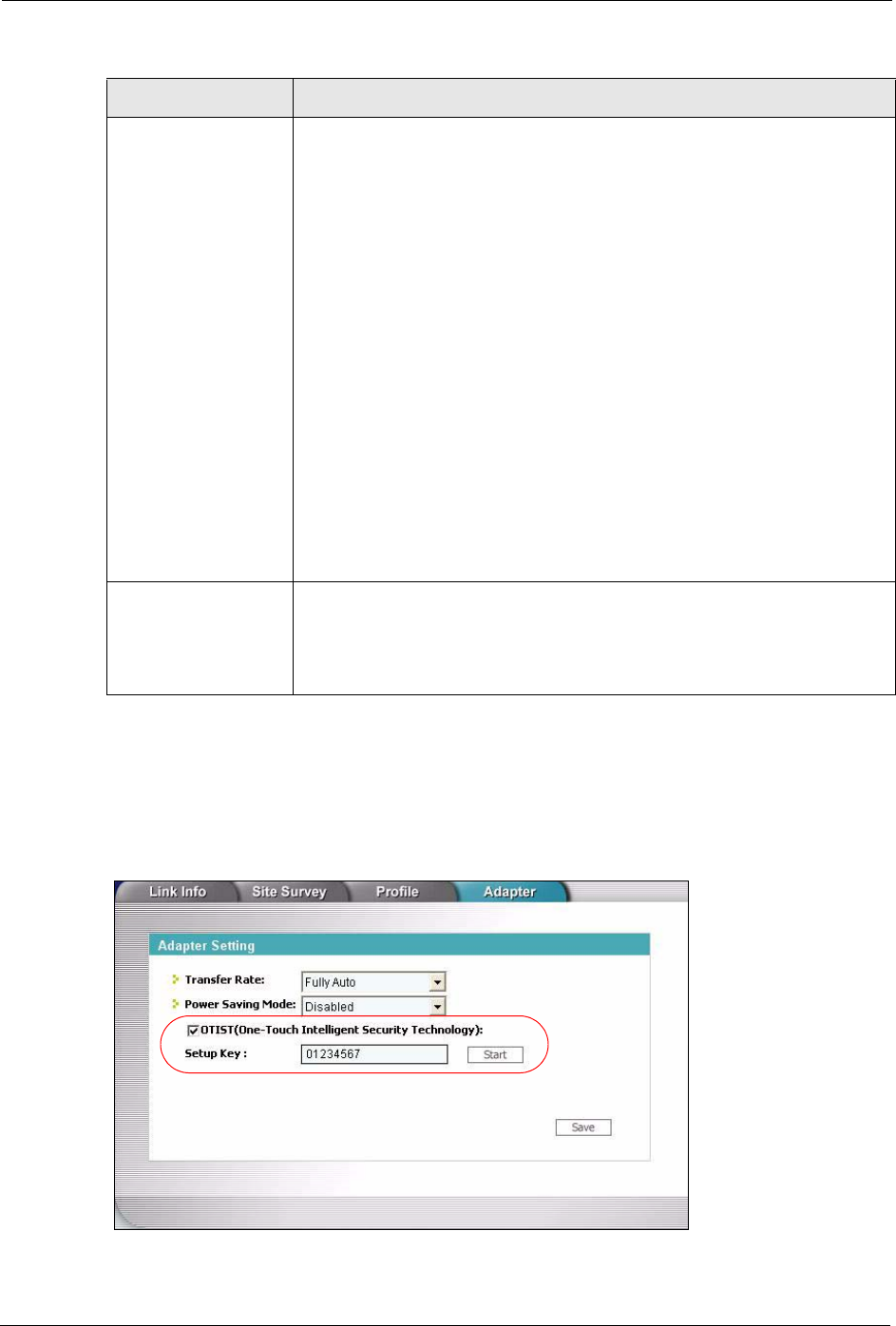
Start the ZyXEL utility and click the Adapter tab. Select the OTIST check box, enter the
same Setup Key as your AP’s and click Save.
Figure 36 Example Wireless Client OTIST Screen
Yes! To have OTIST automatically generate a WPA-PSK key, select this check box.
If you manually configured a WEP key or a WPA-PSK key and you also select
this check box, then the key you manually configured is used.
If you want to configure your own WPA-PSK and have OTIST use that WPA-
PSK, you must:
• Configure a WPA-PSK in the Wireless General screen.
• Clear the Yes! checkbox in the OTIST screen and click Apply.
Note: If you already have a WPA-PSK configured in the
Wireless General screen, and you run OTIST with Yes!
selected, OTIST will not replace the WPA-PSK. Clear the
checkbox in the OTIST screen.
If you want OTIST to automatically generate a WPA-PSK, you must:
• Change your security to No Security in the Wireless General screen.
• Select the the Yes! checkbox in the OTIST screen and click Apply.
• The Wireless General screen displays an auto generated WPA-PSK and
is now in WPA-PSK security mode.
The WPA-PSK security settings are assigned to the wireless client when you
start OTIST.
Start Click Start to encrypt the wireless security data using the setup key and have
the Prestige set the wireless station to use the same wireless settings as the
Prestige. You must also activate and start OTIST on the wireless station at the
same time.
The process takes three minutes to complete.
Table 26 Wireless: OTIST
LABEL DESCRIPTION
P-320W User’s Guide
Chapter 4 Wireless LAN 75
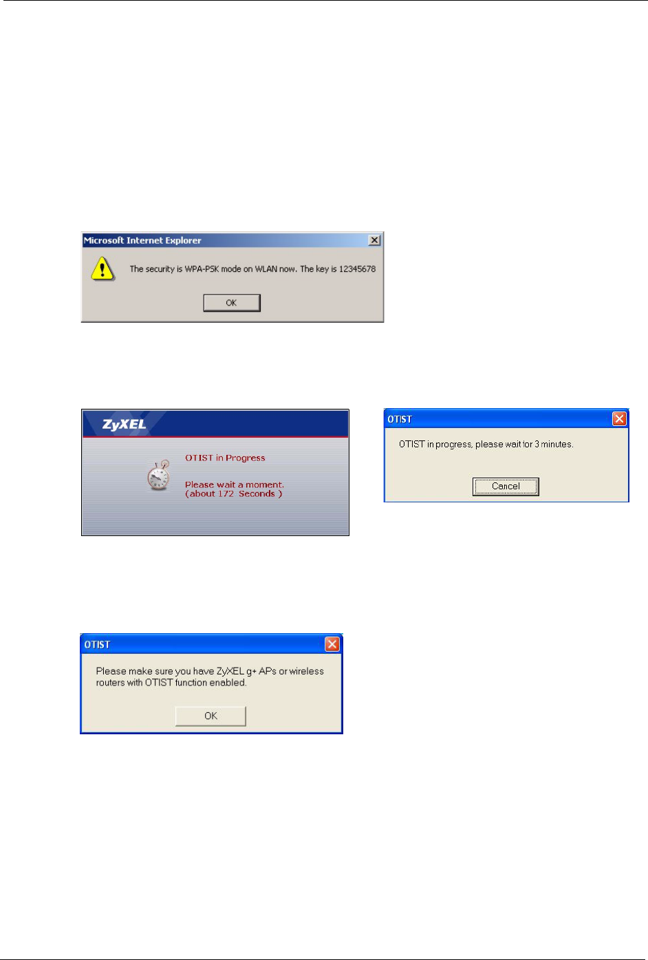
4.5.2 Starting OTIST
Note: You must click Start in the AP OTIST web configurator screen and in the
wireless client(s) Adapter screen all within three minutes (at the time of
writing). You can start OTIST in the wireless clients and AP in any order but
they must all be within range and have OTIST enabled.
1In the AP, a web configurator screen pops up showing you the security settings to
transfer. After reviewing the settings, click OK.
Figure 37 Security Key
2This screen appears while OTIST settings are being transferred. It closes when the
transfer is complete.
Figure 38 OTIST in Progress (AP) Figure 39 OTIST in Progress (Client)
• In the wireless client, you see this screen if it can't find an OTIST-enabled AP (with the
same Setup key). Click OK to go back to the ZyXEL utility main screen.
Figure 40 No AP with OTIST Found
• If there is more than one OTIST-enabled AP within range, you see a screen asking you to
select one AP to get settings from.
4.5.3 Notes on OTIST
1If you enabled OTIST in the wireless client, you see this screen each time you start the
utility. Click Ye s for it to search for an OTIST-enabled AP.

P-320W User’s Guide
76 Chapter 4 Wireless LAN
Figure 41 Start OTIST?
2If an OTIST-enabled wireless client loses its wireless connection for more than ten
seconds, it will search for an OTIST-enabled AP for up to one minute. (If you manually
have the wireless client search for an OTIST-enabled AP, there is no timeout; click
Cancel in the OTIST progress screen to stop the search.)
3When the wireless client finds an OTIST-enabled AP, you must still click Start in the AP
OTIST web configurator screen or hold in the Reset button (for one or two seconds) for
the AP to transfer settings.
4If you change the SSID or the keys on the AP after using OTIST, you need to run OTIST
again or enter them manually in the wireless client(s).
5If you configure OTIST to generate a WPA-PSK key, this key changes each time you run
OTIST. Therefore, if a new wireless client joins your wireless network, you need to run
OTIST on the AP and ALL wireless clients again.
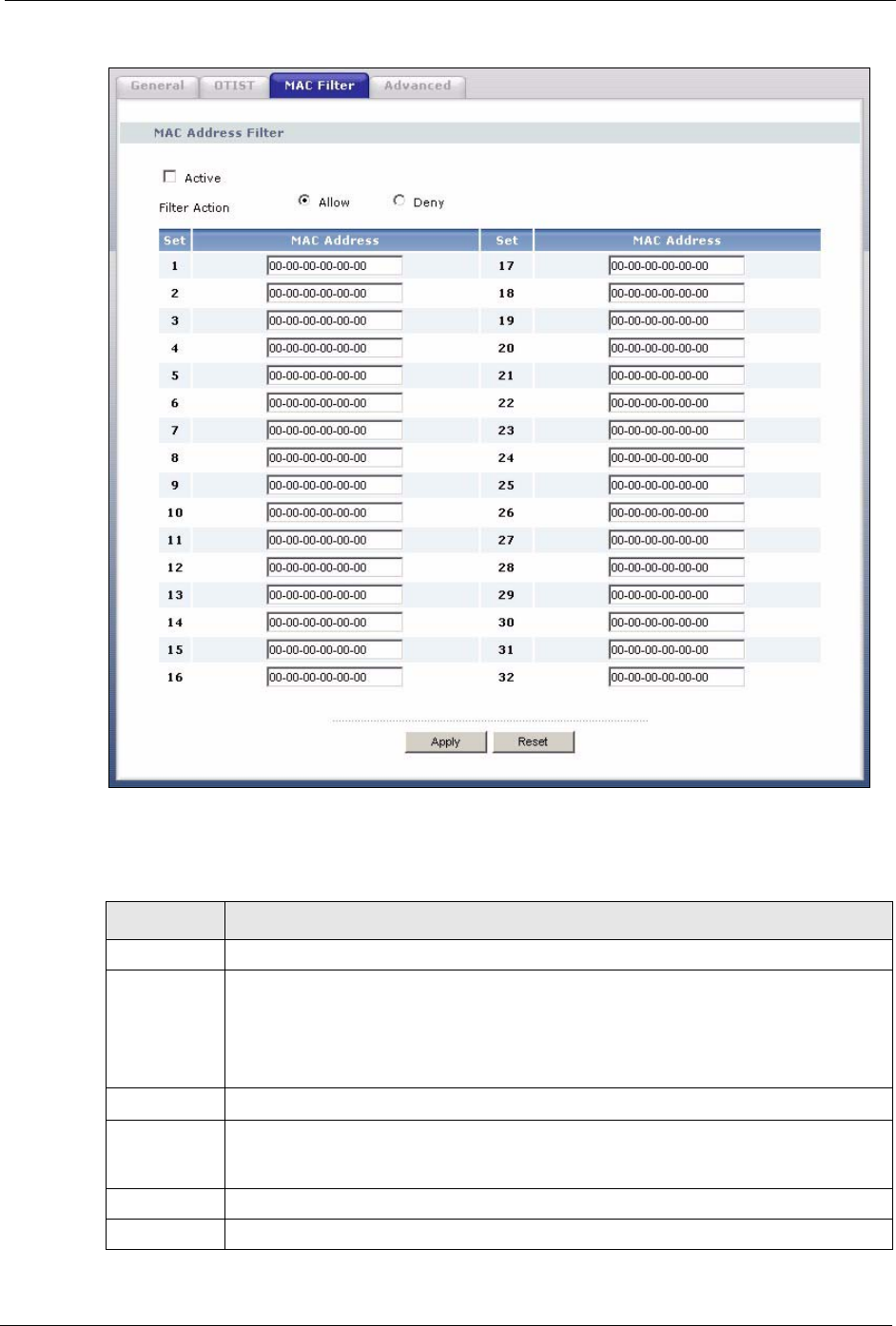
4.6 MAC Filter
The MAC filter screen allows you to configure the Prestige to give exclusive access to up to
32 devices (Allow) or exclude up to 32 devices from accessing the Prestige (Deny). Every
Ethernet device has a unique MAC (Media Access Control) address. The MAC address is
assigned at the factory and consists of six pairs of hexadecimal characters, for example, 00-
A0-C5-00-00-02. You need to know the MAC address of the devices to configure this screen.
To change your Prestige’s MAC filter settings, click the Wireless LAN link under Network
and then the MAC Filter tab. The screen appears as shown.
P-320W User’s Guide
Chapter 4 Wireless LAN 77
Figure 42 Wireless: MAC Address Filter
The following table describes the labels in this menu.
Table 27 MAC Address Filter
LABEL DESCRIPTION
Active Select Yes from the drop down list box to enable MAC address filtering.
Filter Action Define the filter action for the list of MAC addresses in the MAC Address table.
Select Deny to block access to the Prestige, MAC addresses not listed will be allowed
to access the Prestige
Select Allow to permit access to the Prestige, MAC addresses not listed will be denied
access to the Prestige.
Set This is the index number of the MAC address.
MAC Address Enter the MAC addresses of the wireless station that are allowed or denied access to
the Prestige in these address fields. Enter the MAC addresses in a valid MAC address
format, that is, six hexadecimal character pairs, for example, 12:34:56:78:9a:bc.
Apply Click Apply to save your changes back to the Prestige.
Reset Click Reset to reload the previous configuration for this screen.
P-320W User’s Guide
78 Chapter 4 Wireless LAN
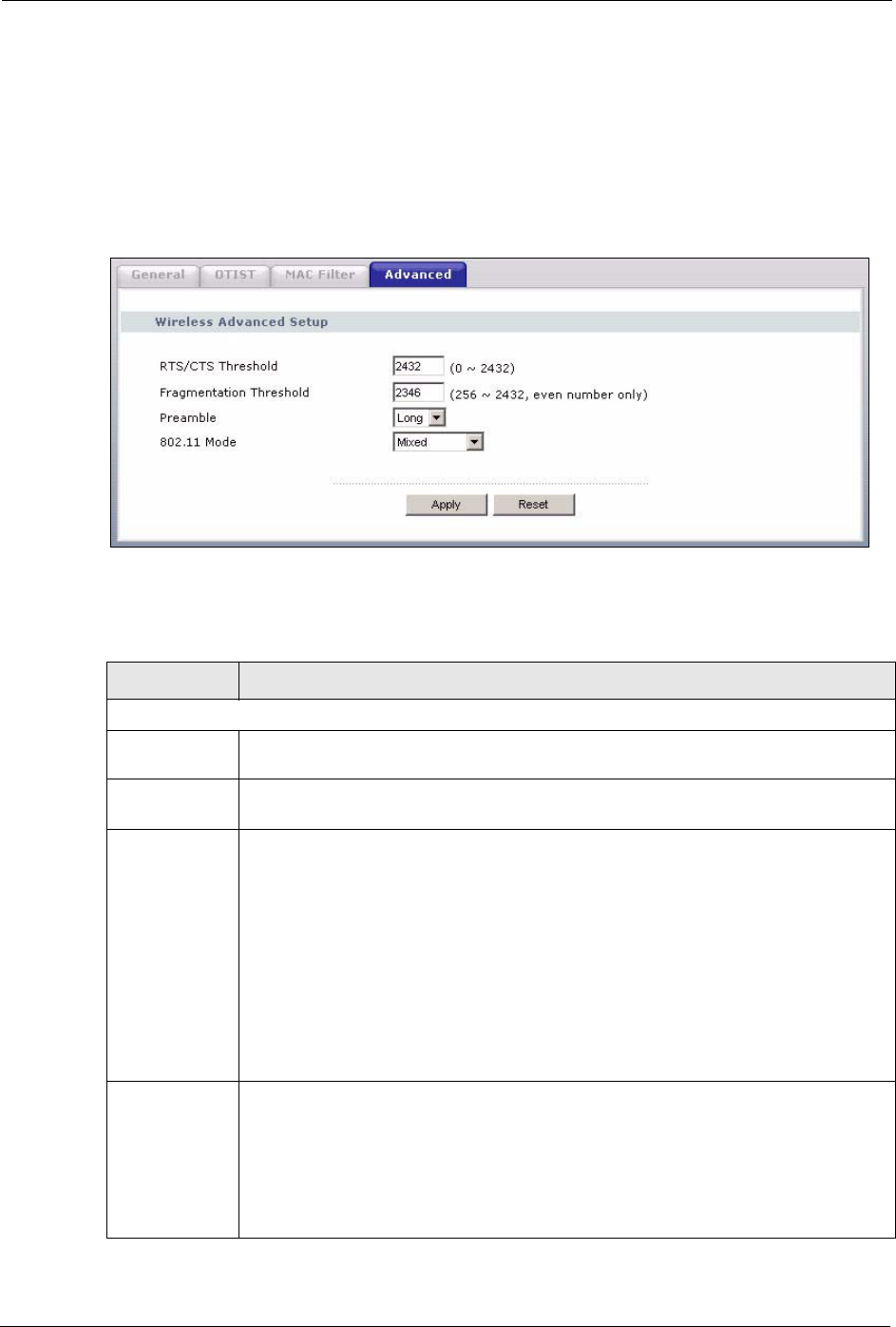
4.7 Wireless LAN Advanced Screen
See the appendix for background information on roaming.
To enable roaming on your Prestige, click the Wireless LAN link under Network and then the
Advanced tab. The screen appears as shown.
Figure 43 Wireless: Advanced
The following table describes the labels in this screen.
Table 28 Wireless: Advanced
LABEL DESCRIPTION
Wireless Advanced Setup
RTS/CTS
Threshold
Enter a value between 0 and 2432.
Fragmentation
Threshold
It is the maximum data fragment size that can be sent. Enter a value between 256 and
2432.
Preamble Preamble is used to signal that data is coming to the receiver.
Short preamble increases performance as less time sending preamble means more
time for sending data. All IEEE 802.11b compliant wireless adapters support long
preamble, but not all support short preamble.
Select Long preamble if you are unsure what preamble mode the wireless adapters
support, and to provide more reliable communications in busy wireless networks.
Select Short preamble if you are sure the wireless adapters support it, and to provide
more efficient communications.
Note: The Prestige and the wireless stations MUST use the same
preamble mode in order to communicate.
802.11 Mode Select 802.11b Only to allow only IEEE 802.11b compliant WLAN devices to
associate with the Prestige.
Select 802.11g Only to allow only IEEE 802.11g compliant WLAN devices to
associate with the Prestige.
Select Mixed to allow either IEEE802.11b or IEEE802.11g compliant WLAN devices
to associate with the Prestige. The transmission rate of your Prestige might be
reduced.

P-320W User’s Guide
Chapter 4 Wireless LAN 79
Apply Click Apply to save your changes back to the Prestige.
Reset Click Reset to reload the previous configuration for this screen.
Table 28 Wireless: Advanced
LABEL DESCRIPTION

P-320W User’s Guide
80 Chapter 4 Wireless LAN

P-320W User’s Guide
Chapter 5 WAN 81
CHAPTER 5
WAN
This chapter describes how to configure WAN settings.
5.1 WAN IP Address Assignment
Every computer on the Internet must have a unique IP address. If your networks are isolated
from the Internet, for instance, only between your two branch offices, you can assign any IP
addresses to the hosts without problems. However, the Internet Assigned Numbers Authority
(IANA) has reserved the following three blocks of IP addresses specifically for private
networks.
Table 29 Private IP Address Ranges
10.0.0.0 -10.255.255.255
172.16.0.0 -172.31.255.255
192.168.0.0 -192.168.255.255
You can obtain your IP address from the IANA, from an ISP or have it assigned by a private
network. If you belong to a small organization and your Internet access is through an ISP, the
ISP can provide you with the Internet addresses for your local networks. On the other hand, if
you are part of a much larger organization, you should consult your network administrator for
the appropriate IP addresses.
Note: Regardless of your particular situation, do not create an arbitrary IP address;
always follow the guidelines above. For more information on address
assignment, please refer to RFC 1597, Address Allocation for Private Internets
and RFC 1466, Guidelines for Management of IP Address Space.
5.2 IP Address and Subnet Mask
Similar to the way houses on a street share a common street name, so too do computers on a
LAN share one common network number.
Where you obtain your network number depends on your particular situation. If the ISP or
your network administrator assigns you a block of registered IP addresses, follow their
instructions in selecting the IP addresses and the subnet mask.

P-320W User’s Guide
82 Chapter 5 WAN
If the ISP did not explicitly give you an IP network number, then most likely you have a single
user account and the ISP will assign you a dynamic IP address when the connection is
established. The Internet Assigned Number Authority (IANA) reserved this block of addresses
specifically for private use; please do not use any other number unless you are told otherwise.
Let's say you select 192.168.1.0 as the network number; which covers 254 individual
addresses, from 192.168.1.1 to 192.168.1.254 (zero and 255 are reserved). In other words, the
first three numbers specify the network number while the last number identifies an individual
computer on that network.
Once you have decided on the network number, pick an IP address that is easy to remember,
for instance, 192.168.1.1, for your Prestige, but make sure that no other device on your
network is using that IP address.
The subnet mask specifies the network number portion of an IP address. Your Prestige will
compute the subnet mask automatically based on the IP address that you entered. You don't
need to change the subnet mask computed by the Prestige unless you are instructed to do
otherwise.
5.3 DNS Server Address Assignment
Use DNS (Domain Name System) to map a domain name to its corresponding IP address and
vice versa, for instance, the IP address of www.zyxel.com is 204.217.0.2. The DNS server is
extremely important because without it, you must know the IP address of a computer before
you can access it.
The Prestige can get the DNS server addresses in the following way.
1The ISP tells you the DNS server addresses, usually in the form of an information sheet,
when you sign up. If your ISP gives you DNS server addresses, enter them in the DNS
Server fields in DHCP Setup.
If the ISP did not give you DNS server information, leave the DNS Server fields in DHCP
Setup set to 0.0.0.0 for the ISP to dynamically assign the DNS server IP addresses.
5.4 TCP/IP Priority (Metric)
The metric represents the "cost of transmission". A router determines the best route for
transmission by choosing a path with the lowest "cost". RIP routing uses hop count as the
measurement of cost, with a minimum of "1" for directly connected networks. The number
must be between "1" and "15"; a number greater than "15" means the link is down. The
smaller the number, the lower the "cost".
The metric sets the priority for the Prestige’s routes to the Internet. If the routes have the same
metric, the Prestige uses the following pre-defined priorities:
1WAN: designated by the ISP or a static route (see Chapter 10 on page 115)

P-320W User’s Guide
Chapter 5 WAN 83
2Traffic Redirect (see Section 5.9 on page 90)
For example, if WA N has a metric of "1" and Traffic Redirect has a metric of "2", the WA N
connection acts as the primary default route. If the WA N route fails to connect to the Internet,
the Prestige tries Traffic Redirect next.
5.5 WAN MAC Address
Every Ethernet device has a unique MAC (Media Access Control) address. The MAC address
is assigned at the factory and consists of six pairs of hexadecimal characters, for example, 00-
A0-C5-00-00-02.
You can configure the WAN port's MAC address by either using the factory default or cloning
the MAC address from a computer on your LAN. Once it is successfully configured, the
address will be copied to the "rom" file (ZyNOS configuration file). It will not change unless
you change the setting or upload a different "rom" file.
Table 30 Example of Network Properties for LAN Servers with Fixed IP Addresses
Choose an IP address 192.168.1.2-192.168.1.32; 192.168.1.65-192.168.1.254.
Subnet mask 255.255.255.0
Gateway (or default route) 192.168.1.1(Prestige LAN IP)
5.6 Internet Connection
To change your Prestige’s WAN ISP, IP and MAC settings, click WA N under Network. The
screen differs by the encapsulation.
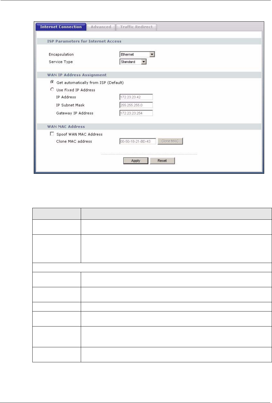
5.6.1 Ethernet Encapsulation
The screen shown next is for Ethernet encapsulation.
P-320W User’s Guide
84 Chapter 5 WAN
Figure 44 WAN: Ethernet Encapsulation
The following table describes the labels in this screen.
Table 31 WAN: Ethernet Encapsulation
LABEL DESCRIPTION
Encapsulation You must choose the Ethernet option when the WAN port is used as a regular
Ethernet.
Service Type Choose from Standard, Telstra (RoadRunner Telstra authentication method),
RR-Manager (Roadrunner Manager authentication method), RR-Toshiba
(Roadrunner Toshiba authentication method) or Telia Login.
The following fields do not appear with the Standard service type.
WAN IP Address Assignment
Get automatically
from ISP
Select this option If your ISP did not assign you a fixed IP address. This is the
default selection.
Use fixed IP
address
Select this option If the ISP assigned a fixed IP address.
IP Address Enter your WAN IP address in this field if you selected Use Fixed IP Address.
Remote IP
Subnet Mask
Enter the Remote IP Subnet Mask (if your ISP gave you one) in this field.
Backup
Gateway IP
Address
Enter a Backup Gateway IP Address (if your ISP gave you one) in this field.
WAN MAC
Address

P-320W User’s Guide
Chapter 5 WAN 85
5.6.2 PPPoE Encapsulation
The Prestige supports PPPoE (Point-to-Point Protocol over Ethernet). PPPoE is an IETF
standard (RFC 2516) specifying how a personal computer (PC) interacts with a broadband
modem (DSL, cable, wireless, etc.) connection. The PPP over Ethernet option is for a dial-
up connection using PPPoE.
For the service provider, PPPoE offers an access and authentication method that works with
existing access control systems (for example RADIUS).
One of the benefits of PPPoE is the ability to let you access one of multiple network services,
a function known as dynamic service selection. This enables the service provider to easily
create and offer new IP services for individuals.
Operationally, PPPoE saves significant effort for both you and the ISP or carrier, as it requires
no specific configuration of the broadband modem at the customer site.
By implementing PPPoE directly on the Prestige (rather than individual computers), the
computers on the LAN do not need PPPoE software installed, since the Prestige does that part
of the task. Furthermore, with NAT, all of the LANs’ computers will have access.
The screen shown next is for PPPoE encapsulation.
Spoof WAN MAC
Address
The MAC address section allows users to configure the WAN port's MAC address
by either using the factory default or cloning the MAC address from a computer on
your LAN.
Clear the check box to use the factory assigned default MAC Address.
Select this option and and click Clone MAC to clone the MAC address in the MAC
Address field.
Clone MAC
address
Enter the MAC address of the computer on the LAN whose MAC you are cloning.
Once it is successfully configured, the address will be copied to the rom file
(ZyNOS configuration file). It will not change unless you change the setting or
upload a different ROM file.
Apply Click Apply to save your changes back to the Prestige.
Reset Click Reset to begin configuring this screen afresh.
Table 31 WAN: Ethernet Encapsulation
LABEL DESCRIPTION
P-320W User’s Guide
86 Chapter 5 WAN
Figure 45 WAN: PPPoE Encapsulation
The following table describes the labels in this screen.
Table 32 WAN: PPPoE Encapsulation
LABEL DESCRIPTION
ISP Parameters for Internet Access
Encapsulation The PPP over Ethernet choice is for a dial-up connection using PPPoE. The
Prestige supports PPPoE (Point-to-Point Protocol over Ethernet). PPPoE is an
IETF standard (RFC 2516) specifying how a personal computer (PC) interacts with
a broadband modem (i.e. xDSL, cable, wireless, etc.) connection. Operationally,
PPPoE saves significant effort for both the end user and ISP/carrier, as it requires
no specific configuration of the broadband modem at the customer site. By
implementing PPPoE directly on the router rather than individual computers, the
computers on the LAN do not need PPPoE software installed, since the router does
that part of the task. Further, with NAT, all of the LAN's computers will have access.
Service Name Type the PPPoE service name provided to you. PPPoE uses a service name to
identify and reach the PPPoE server.
User Name Type the User Name given to you by your ISP.
Password Type the password associated with the User Name above.
Retype to Confirm Type your password again to make sure that you have entered is correctly.
Nailed-Up
Connection
Select Nailed-Up Connection if you do not want the connection to time out.

P-320W User’s Guide
Chapter 5 WAN 87
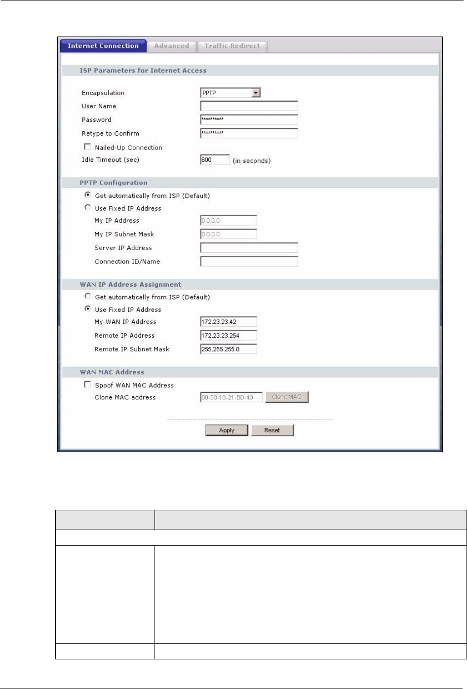
5.6.3 PPTP Encapsulation
Point-to-Point Tunneling Protocol (PPTP) is a network protocol that enables secure transfer of
data from a remote client to a private server, creating a Virtual Private Network (VPN) using
TCP/IP-based networks.
PPTP supports on-demand, multi-protocol and virtual private networking over public
networks, such as the Internet.
The screen shown next is for PPTP encapsulation.
Idle Timeout This value specifies the time in seconds that elapses before the router automatically
disconnects from the PPPoE server.
WAN IP Address Assignment
Get automatically
from ISP
Select this option If your ISP did not assign you a fixed IP address. This is the
default selection.
Use fixed IP
address
Select this option If the ISP assigned a fixed IP address.
My WAN IP
Address
Enter your WAN IP address in this field if you selected Use Fixed IP Address.
Remote IP
Address
Enter the Remote IP Address (if your ISP gave you one) in this field.
Remote IP
Subnet Mask
Enter the Rmote IP subnet Mask in this field.
WAN MAC
Address
Spoof WAN MAC
Address
The MAC address section allows users to configure the WAN port's MAC address
by either using the factory default or cloning the MAC address from a computer on
your LAN.
Clear the check box to use the factory assigned default MAC Address.
Select this option and and click Clone MAC to clone the MAC address in the MAC
Address field.
Clone MAC
address
Enter the MAC address of the computer on the LAN whose MAC you are cloning.
Once it is successfully configured, the address will be copied to the rom file (ZyNOS
configuration file). It will not change unless you change the setting or upload a
different ROM file.
Apply Click Apply to save your changes back to the Prestige.
Reset Click Reset to begin configuring this screen afresh.
Table 32 WAN: PPPoE Encapsulation
LABEL DESCRIPTION
P-320W User’s Guide
88 Chapter 5 WAN
Figure 46 PPTP Encapsulation
The following table describes the labels in this screen.
Table 33 PPTP Encapsulation
LABEL DESCRIPTION
ISP Parameters for Internet Access
Encapsulation Point-to-Point Tunneling Protocol (PPTP) is a network protocol that enables
secure transfer of data from a remote client to a private server, creating a
Virtual Private Network (VPN) using TCP/IP-based networks. PPTP supports
on-demand, multi-protocol, and virtual private networking over public
networks, such as the Internet. The Prestige supports only one PPTP server
connection at any given time.
To configure a PPTP client, you must configure the User Name and
Password fields for a PPP connection and the PPTP parameters for a PPTP
connection.
User Name Type the user name given to you by your ISP.

P-320W User’s Guide
Chapter 5 WAN 89
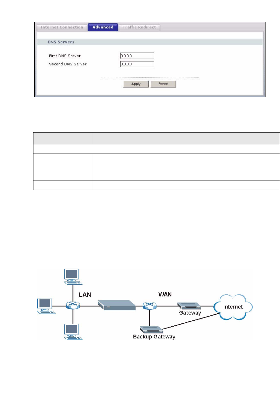
5.7 Advanced WAN Screen
To change your Prestige’s advanced WAN settings, click the WA N link under Network, and
the Advanced tab. The screen appears as shown.
Password Type the password associated with the User Name above.
Retype to Confirm Type your password again to make sure that you have entered is correctly.
Nailed-up Connection Select Nailed-Up Connection if you do not want the connection to time out.
Idle Timeout This value specifies the time in seconds that elapses before the Prestige
automatically disconnects from the PPTP server.
PPTP Configuration
Get automatically from
ISP
Select this option If your ISP did not assign you a fixed IP address. This is the
default selection.
Use fixed IP address Select this option If the ISP assigned a fixed IP address.
My IP Address Type the (static) IP address assigned to you by your ISP.
My IP Subnet Mask Your Prestige will automatically calculate the subnet mask based on the IP
address that you assign. Unless you are implementing subnetting, use the
subnet mask computed by the Prestige.
Server IP Address Type the IP address of the PPTP server.
Connection ID/
Name
Type your identification name for the PPTP server.
WAN IP Address Assignment
Get automatically from
ISP
Select this option If your ISP did not assign you a fixed IP address. This is the
default selection.
Use fixed IP address Select this option If the ISP assigned a fixed IP address.
My WAN IP
Address
Enter your WAN IP address in this field if you selected Use Fixed IP Address.
Remote IP Address Enter the Remote IP Address (if your ISP gave you one) in this field.
Remote IP Subnet
Mask
Enter the Rmote IP subnet Mask in this field.
WAN MAC Address
Spoof WAN MAC
Address
The MAC address section allows users to configure the WAN port's MAC
address by either using the factory default or cloning the MAC address from a
computer on your LAN.
Clear the check box to use the factory assigned default MAC Address.
Select this option and and click Clone MAC to clone the MAC address in the
MAC Address field.
Clone MAC address Enter the MAC address of the computer on the LAN whose MAC you are
cloning. Once it is successfully configured, the address will be copied to the
rom file (ZyNOS configuration file). It will not change unless you change the
setting or upload a different ROM file.
Apply Click Apply to save your changes back to the Prestige.
Reset Click Reset to begin configuring this screen afresh.
Table 33 PPTP Encapsulation
LABEL DESCRIPTION
P-320W User’s Guide
90 Chapter 5 WAN
Figure 47 Advanced
The following table describes the labels in this screen.
Table 34 Advanced
LABEL DESCRIPTION
DNS Servers
First DNS Server
Second DNS Server
Enter the IP address(es) of the DNS server(s). If you do not configure a DNS
server, you must know the IP address of a computer in order to access it.
Apply Click Apply to save your changes back to the Prestige.
Reset Click Reset to begin configuring this screen afresh.
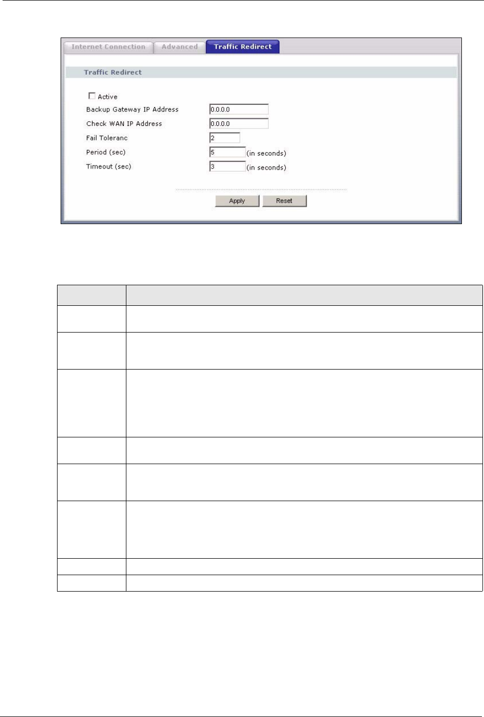
5.8 Traffic Redirect
Traffic redirect forwards WAN traffic to a backup gateway when the Prestige cannot connect
to the Internet through its normal gateway. Connect the backup gateway on the WAN so that
the Prestige still provides firewall protection.
Figure 48 Traffic Redirect WAN Setup
5.9 Traffic Redirect Screen
To change your Prestige’s Traffic Redirect settings, click the WAN link under Network and
the Traffic Redirect tab. The screen appears as shown.
P-320W User’s Guide
Chapter 5 WAN 91
Figure 49 WAN: Traffic Redirect
The following table describes the labels in this screen.
Table 35 Traffic Redirect
LABEL DESCRIPTION
Active Select this check box to have the Prestige use traffic redirect if the normal WAN
connection goes down.
Backup
Gateway IP
Address
Type the IP address of your backup gateway in dotted decimal notation. The Prestige
automatically forwards traffic to this IP address if the Prestige's Internet connection
terminates.
Check WAN IP
Address
Configuration of this field is optional. If you do not enter an IP address here, the
Prestige will use the default gateway IP address. Configure this field to test your
Prestige's WAN accessibility. Type the IP address of a reliable nearby computer (for
example, your ISP's DNS server address). If you are using PPTP or PPPoE
Encapsulation, type "0.0.0.0" to configure the Prestige to check the PVC (Permanent
Virtual Circuit) or PPTP tunnel.
Fail Tolerance Type the number of times your Prestige may attempt and fail to connect to the Internet
before traffic is forwarded to the backup gateway.
Period
(seconds)
Type the number of seconds for the Prestige to wait between checks to see if it can
connect to the WAN IP address (Check WAN IP Address field) or default gateway.
Allow more time if your destination IP address handles lots of traffic.
Timeout
(seconds)
Type the number of seconds for your Prestige to wait for a ping response from the IP
Address in the Check WAN IP Address field before it times out. The WAN connection
is considered "down" after the Prestige times out the number of times specified in the
Fail Tolerance field. Use a higher value in this field if your network is busy or
congested.
Apply Click Apply to save your changes back to the Prestige.
Reset Click Reset to begin configuring this screen afresh.

P-320W User’s Guide
92 Chapter 5 WAN

P-320W User’s Guide
Chapter 6 LAN 93
CHAPTER 6
LAN
This chapter describes how to configure LAN settings.
6.1 LAN Overview
Local Area Network (LAN) is a shared communication system to which many computers are
attached. The LAN screens can help you configure a LAN DHCP server, manage IP addresses,
and partition your physical network into logical networks.
6.1.1 IP Pool Setup
The Prestige is pre-configured with a pool of 32 IP addresses starting from 192.168.1.33 to
192.168.1.64. This configuration leaves 31 IP addresses (excluding the Prestige itself) in the
lower range for other server computers, for instance, servers for mail, FTP, TFTP, web, etc.,
that you may have.
6.1.2 System DNS Servers
Refer to the IP Address and Subnet Mask section in the Wizard Connection chapter.
6.2 LAN TCP/IP
The Prestige has built-in DHCP server capability that assigns IP addresses and DNS servers to
systems that support DHCP client capability.
6.2.1 Factory LAN Defaults
The LAN parameters of the Prestige are preset in the factory with the following values:
• IP address of 192.168.1.1 with subnet mask of 255.255.255.0 (24 bits)
• DHCP server enabled with 32 client IP addresses starting from 192.168.1.33.
These parameters should work for the majority of installations. If your ISP gives you explicit
DNS server address(es), read the embedded web configurator help regarding what fields need
to be configured.
P-320W User’s Guide
94 Chapter 6 LAN
6.2.2 IP Address and Subnet Mask
Refer to the section about IP address and subnet mask in the Wizard Setup chapter for this
information.
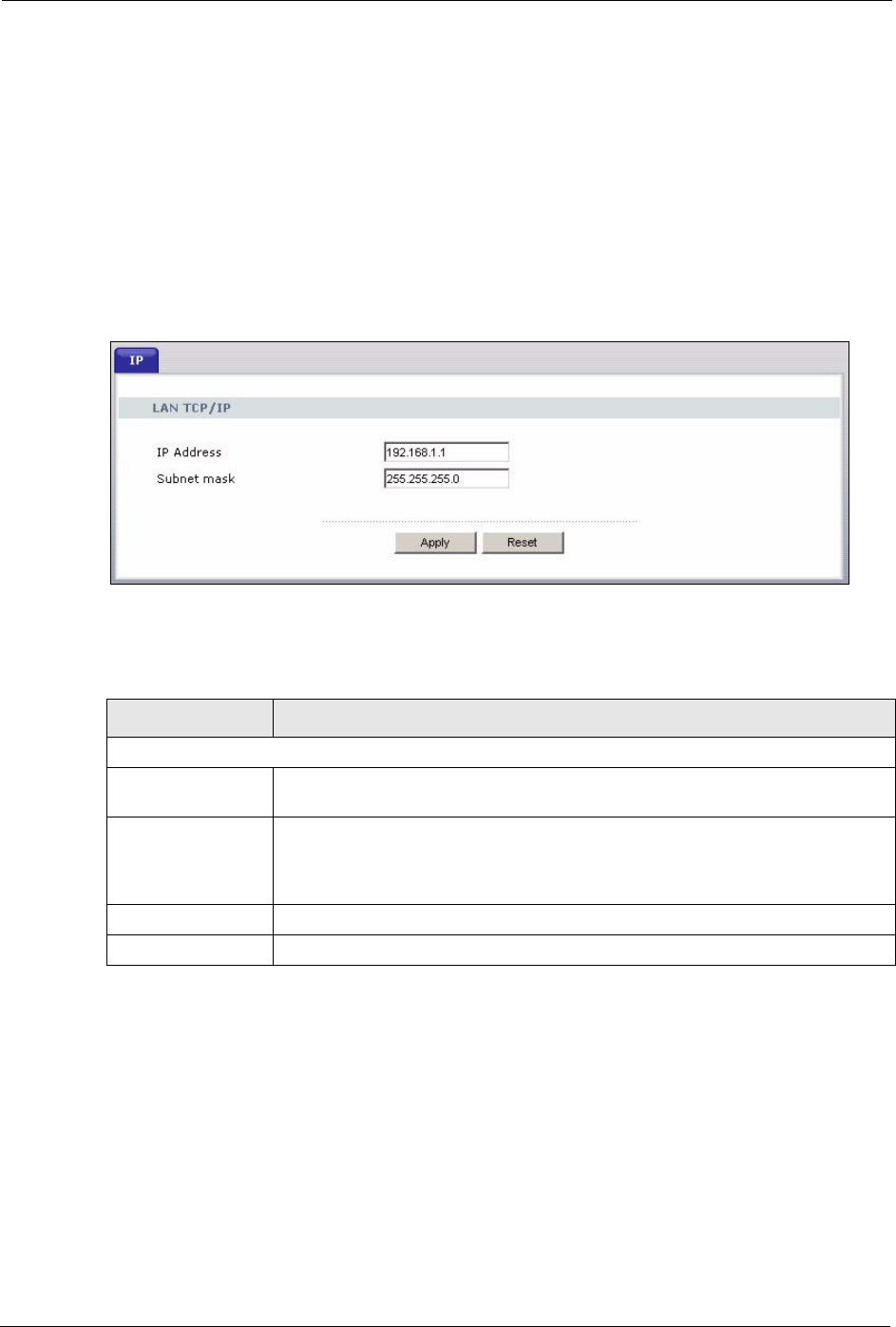
6.3 IP Screen
Click the LAN link under Network to open the IP screen.
Figure 50 LAN IP
The following table describes the labels in this screen.
Table 36 LAN IP
LABEL DESCRIPTION
LAN TCP/IP
IP Address Type the IP address of your Prestige in dotted decimal notation 192.168.1.1
(factory default).
IP Subnet Mask The subnet mask specifies the network number portion of an IP address. Your
Prestige will automatically calculate the subnet mask based on the IP address
that you assign. Unless you are implementing subnetting, use the subnet mask
computed by the Prestige 255.255.255.0.
Apply Click Apply to save your changes back to the Prestige.
Reset Click Reset to begin configuring this screen afresh.
P-320W User’s Guide
Chapter 7 DHCP Server 95
CHAPTER 7
DHCP Server
7.1 DHCP
DHCP (Dynamic Host Configuration Protocol, RFC 2131 and RFC 2132) allows individual
clients to obtain TCP/IP configuration at start-up from a server. You can configure the Prestige
as a DHCP server or disable it. When configured as a server, the Prestige provides the TCP/IP
configuration for the clients. If DHCP service is disabled, you must have another DHCP server
on your LAN, or else the computer must be manually configured.
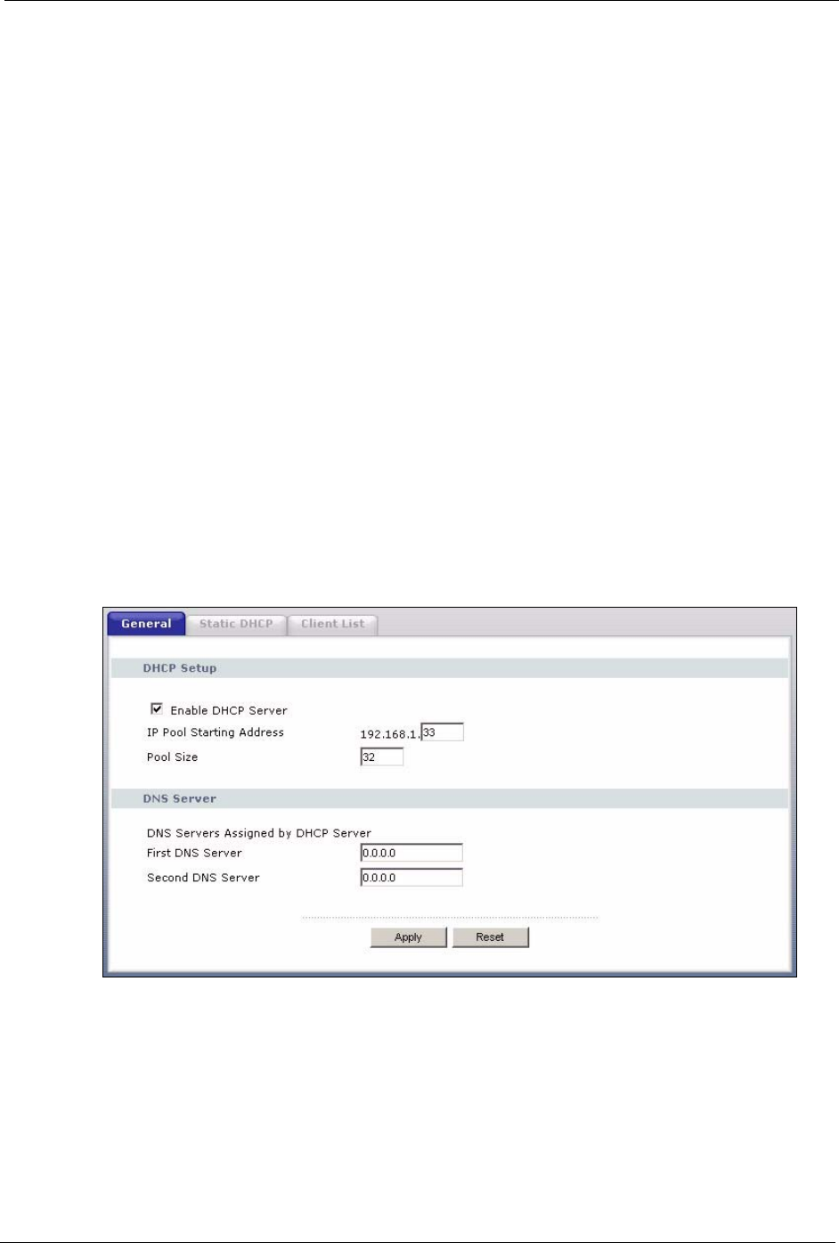
7.2 DHCP Screen
Click the DHCP Server link under Network and the General tab. The following screen
displays.
Figure 51 General

P-320W User’s Guide
96 Chapter 7 DHCP Server
The following table describes the labels in this screen.
Table 37 General
LABEL DESCRIPTION
Enable DHCP Server DHCP (Dynamic Host Configuration Protocol, RFC 2131 and RFC 2132)
allows individual clients (computers) to obtain TCP/IP configuration at startup
from a server. Leave the Enable DHCP Server check box selected unless
your ISP instructs you to do otherwise. Clear it to disable the Prestige acting
as a DHCP server. When configured as a server, the Prestige provides TCP/IP
configuration for the clients. If not, DHCP service is disabled and you must
have another DHCP server on your LAN, or else the computers must be
manually configured. When set as a server, fill in the following four fields.
IP Pool Starting
Address
This field specifies the first of the contiguous addresses in the IP address pool.
Pool Size This field specifies the size, or count of the IP address pool.
DNS Servers Assigned by DHCP Server
The Prestige passes a DNS (Domain Name System) server IP address (in the order you specify here)
to the DHCP clients. The Prestige only passes this information to the LAN DHCP clients when you
select the Enable DHCP Server check box. When you clear the Enable DHCP Server check box,
DHCP service is disabled and you must have another DHCP sever on your LAN, or else the computers
must have their DNS server addresses manually configured.
First DNS Server
Second DNS Server
Enter the IP address(es) of the DNS server(s). If you do not configure a DNS
server, you must know the IP address of a computer in order to access it.
Apply Click Apply to save your changes back to the Prestige.
Reset Click Reset to begin configuring this screen afresh.
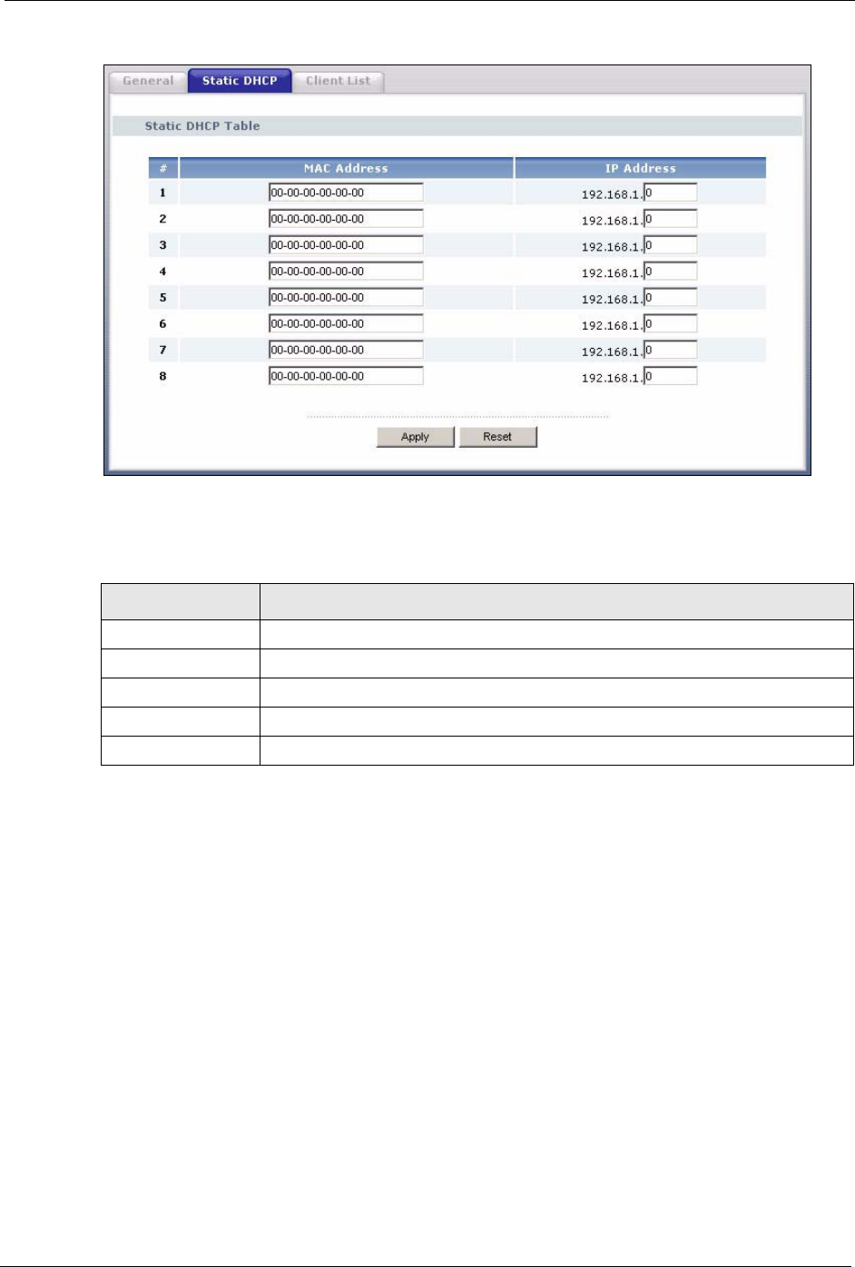
7.3 Static DHCP Screen
This table allows you to assign IP addresses on the LAN to specific individual computers
based on their MAC addresses.
Every Ethernet device has a unique MAC (Media Access Control) address. The MAC address
is assigned at the factory and consists of six pairs of hexadecimal characters, for example, 00-
A0-C5-00-00-02.
To change your Prestige’s Static DHCP settings, click the DHCP Server link under Network
and the Static DHCP tab. The following screen displays.
P-320W User’s Guide
Chapter 7 DHCP Server 97
Figure 52 Static DHCP
The following table describes the labels in this screen.
Table 38 Static DHCP
LABEL DESCRIPTION
#This is the index number of the Static IP table entry (row).
MAC Address Type the MAC address (with colons) of a computer on your LAN.
IP Address Type the LAN IP address of a computer on your LAN.
Apply Click Apply to save your changes back to the Prestige.
Reset Click Reset to begin configuring this screen afresh.
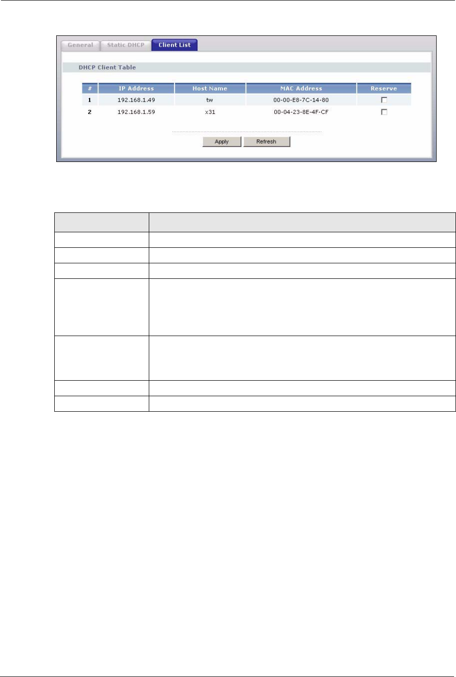
7.4 Client List Screen
The DHCP table shows current DHCP client information (including IP Address, Host Name
and MAC Address) of all network clients using the Prestige’s DHCP server.
Configure this screen to always assign an IP address to a MAC address (and host name). Click
the DHCP Server link under Network and the Client List tab.
Note: You can also view a read-only client list by clicking the DHCP Table (Detail)
hyperlink in the Status screen.
The following screen displays.
P-320W User’s Guide
98 Chapter 7 DHCP Server
Figure 53 Client List
The following table describes the labels in this screen.
Table 39 Client List
LABEL DESCRIPTION
# This is the index number of the host computer.
IP Address This field displays the IP address relative to the # field listed above.
Host Name This field displays the computer host name.
MAC Address The MAC (Media Access Control) or Ethernet address on a LAN (Local Area
Network) is unique to your computer (six pairs of hexadecimal notation).
A network interface card such as an Ethernet adapter has a hardwired address
that is assigned at the factory. This address follows an industry standard that
ensures no other adapter has a similar address.
Reserve Select this check box to have the Prestige always assign this IP address to this
MAC address (and host name). You can select up to 8 entries in this table.
After you click Apply, the MAC address and IP address also display in the
Static DHCP screen (where you can edit them).
Apply Click Apply to save your changes back to the Prestige.
Refresh Click Refresh to reload the DHCP table.

P-320W User’s Guide
Chapter 8 Network Address Translation (NAT) 99
CHAPTER 8
Network Address Translation
(NAT)
This chapter discusses how to configure NAT on the Prestige.
8.1 NAT Overview
NAT (Network Address Translation - NAT, RFC 1631) is the translation of the IP address of a
host in a packet. For example, the source address of an outgoing packet, used within one
network is changed to a different IP address known within another network.
8.1.1 NAT Definitions
Inside/outside denotes where a host is located relative to the Prestige. For example, the
computers of your subscribers are the inside hosts, while the web servers on the Internet are
the outside hosts.
Global/local denotes the IP address of a host in a packet as the packet traverses a router. For
example, the local address refers to the IP address of a host when the packet is in the local
network, while the global address refers to the IP address of the host when the same packet is
traveling in the WAN side.
Note that inside/outside refers to the location of a host, while global/local refers to the IP
address of a host used in a packet. Thus, an inside local address (ILA) is the IP address of an
inside host in a packet when the packet is still in the local network, while an inside global
address (IGA) is the IP address of the same inside host when the packet is on the WAN side.
The following table summarizes this information.

Table 40 NAT Definitions
TERM DESCRIPTION
Inside This refers to the host on the LAN.
Outside This refers to the host on the WAN.
Local This refers to the packet address (source or destination) as the packet travels on the LAN.
Global This refers to the packet address (source or destination) as the packet travels on the
WAN.
P-320W User’s Guide
100 Chapter 8 Network Address Translation (NAT)
Note: NAT never changes the IP address (either local or global) of an outside host.
8.1.2 What NAT Does
In the simplest form, NAT changes the source IP address in a packet received from a
subscriber (the inside local address) to another (the inside global address) before forwarding
the packet to the WAN side. When the response comes back, NAT translates the destination
address (the inside global address) back to the inside local address before forwarding it to the
original inside host. Note that the IP address (either local or global) of an outside host is never
changed.
The global IP addresses for the inside hosts can be either static or dynamically assigned by the
ISP. In addition, you can designate servers (for example a web server and a telnet server) on
your local network and make them accessible to the outside world. If you do not define any
servers (for Many-to-One and Many-to-Many Overload mapping), NAT offers the additional
benefit of firewall protection. With no servers defined, your Prestige filters out all incoming
inquiries, thus preventing intruders from probing your network. For more information on IP
address translation, refer to RFC 1631, The IP Network Address Translator (NAT).
8.1.3 How NAT Works
Each packet has two addresses – a source address and a destination address. For outgoing
packets, the ILA (Inside Local Address) is the source address on the LAN, and the IGA (Inside
Global Address) is the source address on the WAN. For incoming packets, the ILA is the
destination address on the LAN, and the IGA is the destination address on the WAN. NAT
maps private (local) IP addresses to globally unique ones required for communication with
hosts on other networks. It replaces the original IP source address (and TCP or UDP source
port numbers for Many-to-One and Many-to-Many Overload NAT mapping) in each packet
and then forwards it to the Internet. The Prestige keeps track of the original addresses and port
numbers so incoming reply packets can have their original values restored. The following
figure illustrates this.