ZyXEL Communications P320W 802.11g Wireless Firewall Router User Manual ZyBook
ZyXEL Communications Corporation 802.11g Wireless Firewall Router ZyBook
Contents
- 1. Users Manual 1
- 2. Users Manual 2
- 3. Users Manual 3
- 4. Users Manual 4
- 5. Users Manual 5
Users Manual 3
P-320W User’s Guide
Chapter 8 Network Address Translation (NAT) 101
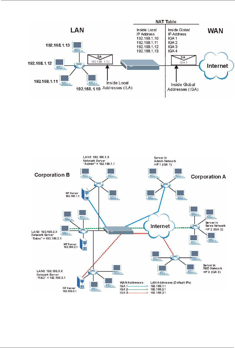
Figure 54 How NAT Works
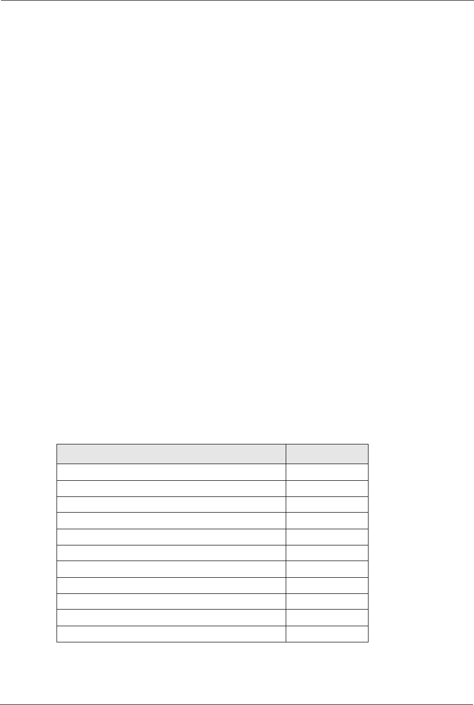
8.1.4 NAT Application
The following figure illustrates a possible NAT application, where three inside LANs (logical
LANs using IP Alias) behind the Prestige can communicate with three distinct WAN
networks. More examples follow at the end of this chapter.
Figure 55 NAT Application With IP Alias
8.1.5 Default Server IP Address
In addition to the servers for specified services, NAT supports a default server IP address. A
default server receives packets from ports that are not specified in this screen
P-320W User’s Guide
102 Chapter 8 Network Address Translation (NAT)
Note: If you do not assign a Default Server IP Address, the Prestige discards all
packets received for ports that are not specified in this screen or remote
management.
8.1.6 Port Forwarding: Services and Port Numbers
A SUA server set is a list of inside (behind NAT on the LAN) servers, for example, web or
FTP, that you can make accessible to the outside world even though NAT makes your whole
inside network appear as a single machine to the outside world.
Use the Port Forwarding page to forward incoming service requests to the server(s) on your
local network. You may enter a single port number or a range of port numbers to be
forwarded, and the local IP address of the desired server. The port number identifies a service;
for example, web service is on port 80 and FTP on port 21. In some cases, such as for
unknown services or where one server can support more than one service (for example both
FTP and web service), it might be better to specify a range of port numbers.
In addition to the servers for specified services, NAT supports a default server. A service
request that does not have a server explicitly designated for it is forwarded to the default
server. If the default is not defined, the service request is simply discarded.
Note: Many residential broadband ISP accounts do not allow you to run any server
processes (such as a Web or FTP server) from your location. Your ISP may
periodically check for servers and may suspend your account if it discovers any
active services at your location. If you are unsure, refer to your ISP.
The most often used port numbers are shown in the following table. Please refer to RFC 1700
for further information about port numbers. Please also refer to the Supporting CD for more
examples and details on SUA/NAT.
Table 41 Services and Port Numbers
SERVICE PORT NUMBER
ECHO 7
FTP (File Transfer Protocol) 21
SMTP (Simple Mail Transfer Protocol) 25
DNS (Domain Name System) 53
Finger 79
HTTP (Hyper Text Transfer protocol or WWW, Web) 80
POP3 (Post Office Protocol) 110
NNTP (Network News Transport Protocol) 119
SNMP (Simple Network Management Protocol) 161
SNMP trap 162
PPTP (Point-to-Point Tunneling Protocol) 1723
P-320W User’s Guide
Chapter 8 Network Address Translation (NAT) 103
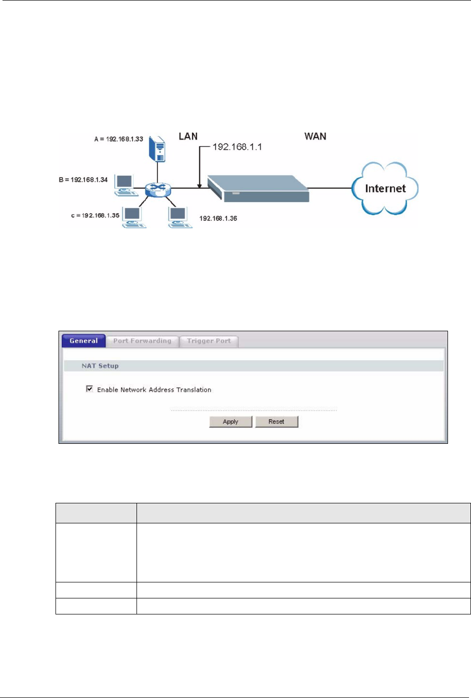
8.1.7 Configuring Servers Behind SUA (Example)
Let's say you want to assign ports 21-25 to one FTP, Telnet and SMTP server (A in the
example), port 80 to another (B in the example) and assign a default server IP address of
192.168.1.35 to a third (C in the example). You assign the LAN IP addresses and the ISP
assigns the WAN IP address. The NAT network appears as a single host on the Internet
Figure 56 Multiple Servers Behind NAT Example
8.2 General NAT Screen
Click the NAT link under Network to open the General screen.
Figure 57 NAT: General
The following table describes the labels in this screen.
Table 42 NAT: General
LABEL DESCRIPTION
Enable Network
Address
Translation
Network Address Translation (NAT) allows the translation of an Internet protocol
address used within one network (for example a private IP address used in a local
network) to a different IP address known within another network (for example a
public IP address used on the Internet).
Select the check box to enable NAT.
Apply Click Apply to save your changes back to the Prestige.
Reset Click Reset to begin configuring this screen afresh.
P-320W User’s Guide
104 Chapter 8 Network Address Translation (NAT)
8.3 Port Forwarding Screen
Ordering your rules is important because the Prestige applies the rules in the order that you
specify. When a rule matches the current packet, the Prestige takes the corresponding action
and the remaining rules are ignored. If there are any empty rules before your new configured
rule, your configured rule will be pushed up by that number of empty rules. For example, if
you have already configured rules 1 to 6 in your current set and now you configure rule
number 9. In the set summary screen, the new rule will be rule 7, not 9. Now if you delete rule
4, rules 5 to 7 will be pushed up by 1 rule, so old rules 5, 6 and 7 become new rules 4, 5 and 6.
Refer to Table 41 on page 102 for port numbers commonly used for particular services.
Note: If you do not assign a Default Server IP Address, the Prestige discards all
packets received for ports that are not specified in this screen or remote
management.
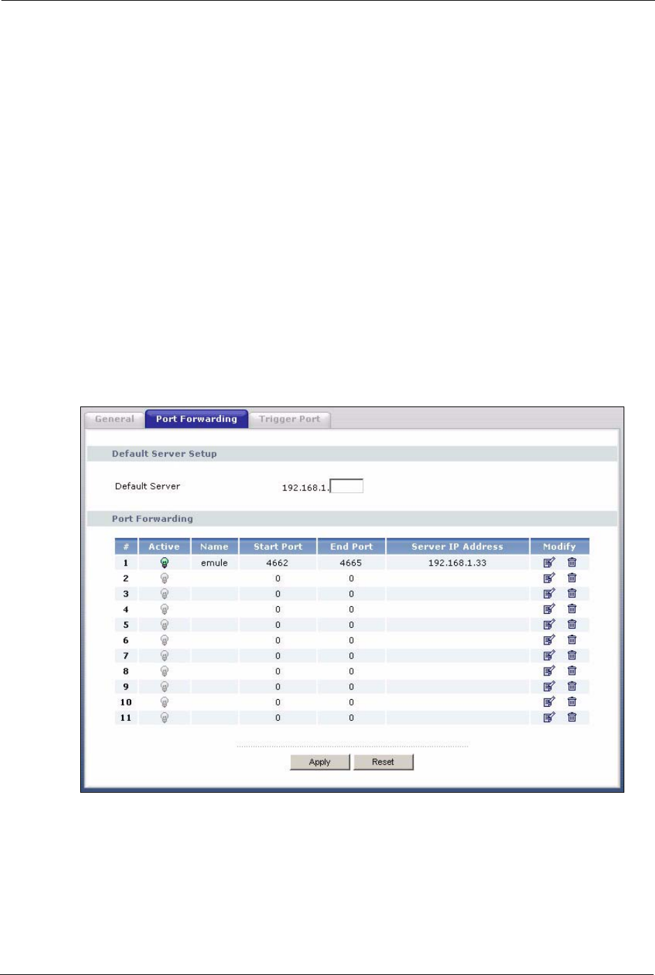
To change your Prestige’s port forwarding settings, click the NAT link under Network and
the Port Forwarding tab. The screen appears as shown.
Figure 58 Port Forwarding
P-320W User’s Guide
Chapter 8 Network Address Translation (NAT) 105
The following table describes the labels in this screen.
Table 43 NAT: Port Forwarding
LABEL DESCRIPTION
Default Server In addition to the servers for specified services, NAT supports a default server. A
default server receives packets from ports that are not specified in this screen.
If you do not assign a Default Server IP Address, the Prestige discards all packets
received for ports that are not specified in this screen or remote management.
#Number of an individual SUA server entry.
Active This icon is turned on when the port forwarding entry is enabled.
Click the edit icon under Modify and select the Active checkbox in the Rule Setup
screen to enable the port forwarding entry.
Clear the checkbox to disable forwarding of these ports to an inside server without
having to delete the entry.
Name This field displays a name to identify this port-forwarding rule.
Start Port This field displays a start port number.
End Port This field displays an end port number. If the same port number as the Start Port is
displayed then a single port is forwarded. If a different number to the Start Port
number is displayed then a range of ports are forwarded.
Server IP Address This field displays the inside IP address of the server.
Modify Click the edit icon to open the address mapping rule screen. Modify an existing rule
or create a new rule in the Rule Setup screen.
Click the delete icon to remove an address mapping rule.
Apply Click Apply to save your changes back to the Prestige.
Reset Click Reset to begin configuring this screen afresh.
8.3.1 Rule Setup Screen
To edit a port forwarding rule, click the edit icon under Modify. The following screen
displays.
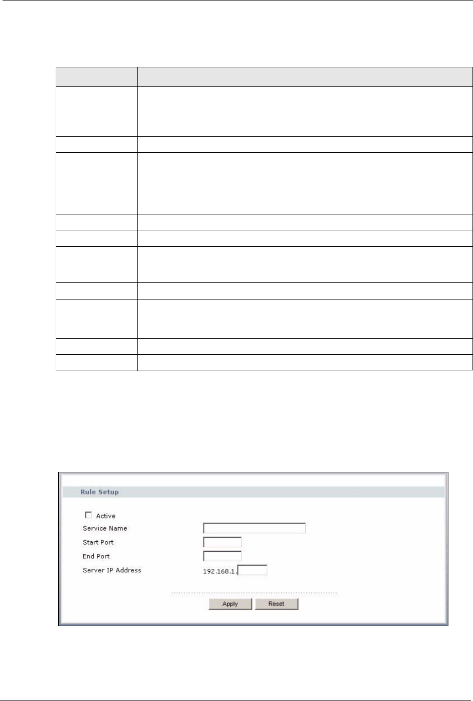
Figure 59 NAT: Port Forwarding: Rule Setup

P-320W User’s Guide
106 Chapter 8 Network Address Translation (NAT)
The following table describes the labels in this screen.
Table 44 NAT: Port Forwarding: Rule Setup
LABEL DESCRIPTION
Active Select the check box to enable this port forwarding entry.
Clear the checkbox to disallow forwarding of these ports to an inside server without
having to delete the entry.
Service Name Type a Service Name to identify this port-forwarding rule.
Start Port Type a start port number. To forward only one port, enter it again in the End Port
field. To specify a range of ports, enter the last port to be forwarded in the End
Port field.
End Port Type an end port number.
Server IP Address Type the inside IP address of the server.
Apply Click Apply to save your changes back to the Prestige.
Cancel Click Cancel to return to the previous screen and not save your changes.
8.4 Trigger Port Forwarding
Some services use a dedicated range of ports on the client side and a dedicated range of ports
on the server side. With regular port forwarding you set a forwarding port in NAT to forward a
service (coming in from the server on the WAN) to the IP address of a computer on the client
side (LAN). The problem is that port forwarding only forwards a service to a single LAN IP
address. In order to use the same service on a different LAN computer, you have to manually
replace the LAN computer's IP address in the forwarding port with another LAN computer's IP
address,
Trigger port forwarding solves this problem by allowing computers on the LAN to
dynamically take turns using the service. The Prestige records the IP address of a LAN
computer that sends traffic to the WAN to request a service with a specific port number and
protocol (a "trigger" port). When the Prestige's WAN port receives a response with a specific
port number and protocol ("incoming" port), the Prestige forwards the traffic to the LAN IP
address of the computer that sent the request. After that computer’s connection for that service
closes, another computer on the LAN can use the service in the same manner. This way you do
not need to configure a new IP address each time you want a different LAN computer to use
the application.
8.4.1 Trigger Port Forwarding Example
The following is an example of trigger port forwarding.
P-320W User’s Guide
Chapter 8 Network Address Translation (NAT) 107
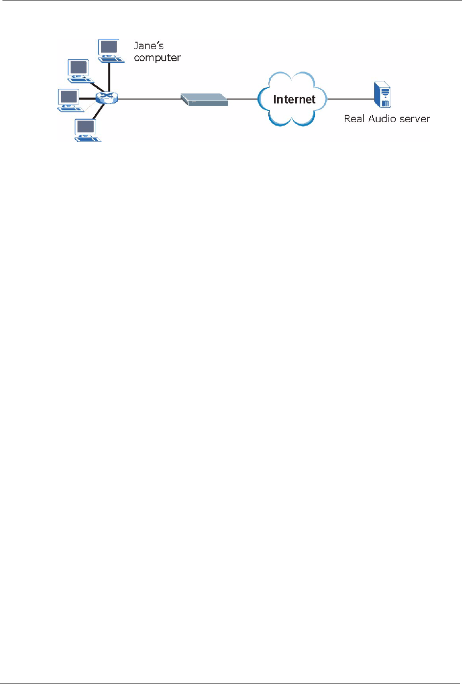
Figure 60 Trigger Port Forwarding Process: Example
1Jane requests a file from the Real Audio server (port 7070).
2Port 7070 is a “trigger” port and causes the Prestige to record Jane’s computer IP address.
The Prestige associates Jane's computer IP address with the "incoming" port range of
6970-7170.
3The Real Audio server responds using a port number ranging between 6970-7170.
4The Prestige forwards the traffic to Jane’s computer IP address.
5Only Jane can connect to the Real Audio server until the connection is closed or times
out. The Prestige times out in three minutes with UDP (User Datagram Protocol), or two
hours with TCP/IP (Transfer Control Protocol/Internet Protocol).
8.4.2 Two Points To Remember About Trigger Ports
1Trigger events only happen on data that is going coming from inside the Prestige and
going to the outside.
2If an application needs a continuous data stream, that port (range) will be tied up so that
another computer on the LAN can’t trigger it.
8.5 Trigger Port Forwarding Screen
To change your Prestige’s trigger port settings, click the NAT link under Network and the
Trigger Port tab. The screen appears as shown.
Note: Only one LAN computer can use a trigger port (range) at a time.
P-320W User’s Guide
108 Chapter 8 Network Address Translation (NAT)
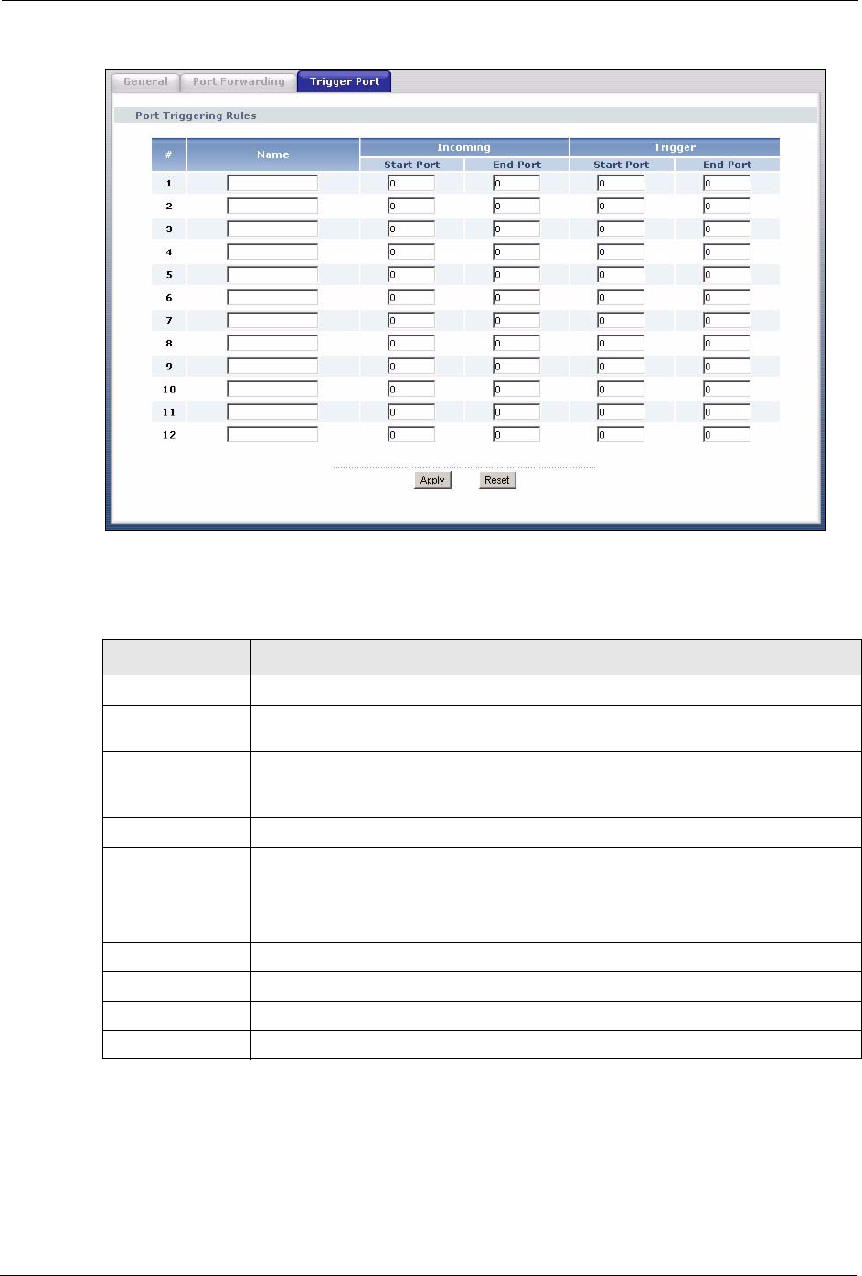
Figure 61 NAT: Trigger Port
The following table describes the labels in this screen.
Table 45 NAT: Trigger Port
LABEL DESCRIPTION
#This is the rule index number (read-only).
Name Type a unique name (up to 15 characters) for identification purposes. All
characters are permitted - including spaces.
Incoming Incoming is a port (or a range of ports) that a server on the WAN uses when it
sends out a particular service. The Prestige forwards the traffic with this port (or
range of ports) to the client computer on the LAN that requested the service.
Start Port Type a port number or the starting port number in a range of port numbers.
End Port Type a port number or the ending port number in a range of port numbers.
Trigger The trigger port is a port (or a range of ports) that causes (or triggers) the Prestige
to record the IP address of the LAN computer that sent the traffic to a server on the
WAN.
Start Port Type a port number or the starting port number in a range of port numbers.
End Port Type a port number or the ending port number in a range of port numbers.
Apply Click Apply to save your changes back to the Prestige.
Reset Click Reset to begin configuring this screen afresh.

P-320W User’s Guide
Chapter 9 Firewall 109
CHAPTER 9
Firewall
This chapter gives some background information on firewalls and explains how to get started
with the Prestige firewall.
9.1 Introduction to Firewall
9.1.1 What is a Firewall?
Originally, the term firewall referred to a construction technique designed to prevent the
spread of fire from one room to another. The networking term "firewall" is a system or group
of systems that enforces an access-control policy between two networks. It may also be
defined as a mechanism used to protect a trusted network from an untrusted network. Of
course, firewalls cannot solve every security problem. A firewall is one of the mechanisms
used to establish a network security perimeter in support of a network security policy. It
should never be the only mechanism or method employed. For a firewall to guard effectively,
you must design and deploy it appropriately. This requires integrating the firewall into a broad
information-security policy. In addition, specific policies must be implemented within the
firewall itself.
9.1.2 Stateful Inspection Firewall.
Stateful inspection firewalls restrict access by screening data packets against defined access
rules. They make access control decisions based on IP address and protocol. They also
"inspect" the session data to assure the integrity of the connection and to adapt to dynamic
protocols. These firewalls generally provide the best speed and transparency; however, they
may lack the granular application level access control or caching that some proxies support.
Firewalls, of one type or another, have become an integral part of standard security solutions
for enterprises.
9.1.3 About the Prestige Firewall
The Prestige firewall is a stateful inspection firewall and is designed to protect against Denial
of Service attacks when activated (click the General tab under Firewall and then click the
Enable Firewall check box). The Prestige's purpose is to allow a private Local Area Network
(LAN) to be securely connected to the Internet. The Prestige can be used to prevent theft,
destruction and modification of data, as well as log events, which may be important to the
security of your network.
The Prestige is installed between the LAN and a broadband modem connecting to the Internet.
This allows it to act as a secure gateway for all data passing between the Internet and the LAN.
P-320W User’s Guide
110 Chapter 9 Firewall
The Prestige has one Ethernet WAN port and four Ethernet LAN ports, which are used to
physically separate the network into two areas.The WAN (Wide Area Network) port attaches
to the broadband (cable or DSL) modem to the Internet.
The LAN (Local Area Network) port attaches to a network of computers, which needs security
from the outside world. These computers will have access to Internet services such as e-mail,
FTP and the World Wide Web. However, "inbound access" is not allowed (by default) unless
the remote host is authorized to use a specific service.
9.1.4 Guidelines For Enhancing Security With Your Firewall
1Change the default password via web configurator.
2Think about access control before you connect to the network in any way, including
attaching a modem to the port.
3Limit who can access your router.
4Don't enable any local service (such as SNMP or NTP) that you don't use. Any enabled
service could present a potential security risk. A determined hacker might be able to find
creative ways to misuse the enabled services to access the firewall or the network.
5For local services that are enabled, protect against misuse. Protect by configuring the
services to communicate only with specific peers, and protect by configuring rules to
block packets for the services at specific interfaces.
6Protect against IP spoofing by making sure the firewall is active.
7Keep the firewall in a secured (locked) room.
9.2 General Firewall Screen
Click the Firewall link under Security to open the General screen.
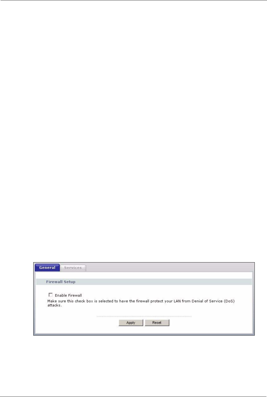
Figure 62 Firewall: General
P-320W User’s Guide
Chapter 9 Firewall 111
The following table describes the labels in this screen.
Table 46 Firewall: General
LABEL DESCRIPTION
Enable Firewall Select this check box to activate the firewall. The Prestige performs access control
and protects against Denial of Service (DoS) attacks when the firewall is activated.
Apply Click Apply to save the settings.
Reset Click Reset to start configuring this screen again.
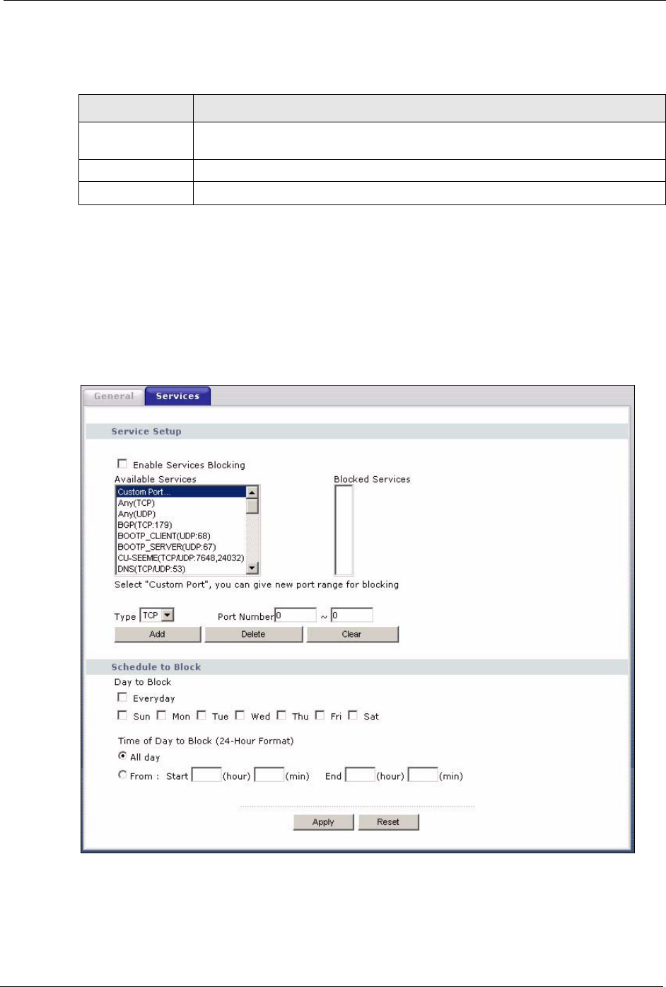
9.3 Services Screen
Click the Firewall link under Security and the Services tab. The screen appears as shown
next. Use this screen to enable service blocking, enter/delete/modify the services you want to
block and the date/time you want to block them.
Figure 63 Firewall: Services

P-320W User’s Guide
112 Chapter 9 Firewall
The following table describes the labels in this screen.
Table 47 Firewall: Services
LABEL DESCRIPTION
Enable Services
Blocking
Select this check box to enable this feature.
Available Services This is a list of pre-defined services (ports) you may prohibit your LAN computers
from using. Please see Section 9.3.1 on page 113 for more information on services
available.
Select the port you want to block using the drop-down list and click Add to add the
port to the Blocked Services field.
Blocked Services This is a list of services (ports) that will be inaccessible to computers on your LAN
once you enable service blocking. Choose the IP port (TCP, UDP or TCP/UDP)
that defines your customized port from the drop down list box.
Custom Port A custom port is a service that is not available in the pre-defined Available
Services list and you must define using the next two fields.
Type Services are either TCP and/or UDP. Select from either TCP or UDP.
Port Number Enter the port number range that defines the service. For example, suppose you
want to define the Gnutella service. Select TCP type and enter a port range from
6345-6349.
Add Select a service from the Available Services drop-down list and then click Add to
add a service to the Blocked Services.
Delete Select a service from the Blocked Services list and then click Delete to remove
this service from the list.
Clear Click Clear to empty the Blocked Services.
Day to Block: Select a check box to configure which days of the week (or everyday) you want the
content filtering to be active.
Time of Day to
Block (24-Hour
Format)
Select the time of day you want service blocking to take effect. Configure blocking
to take effect all day by selecting the All Day check box. You can also configure
specific times that by entering the start time in the Start (hr) and Start (min) fields
and the end time in the End (hr) and End (min) fields. Enter times in 24-hour
format, for example, "3:00pm" should be entered as "15:00".
Apply Click Apply to save the settings.
Reset Click Reset to start configuring this screen again.

P-320W User’s Guide
Chapter 9 Firewall 113
9.3.1 Services
The commonly used services and port numbers are shown in the following table. Please refer
to RFC 1700 for further information about port numbers. Next to the name of the service, two
fields appear in brackets. The first field indicates the IP protocol type (TCP, UDP, or ICMP).
The second field indicates the IP port number that defines the service. (Note that there may be
more than one IP protocol type. For example, look at the DNS service. (UDP/TCP:53) means
UDP port 53 and TCP port 53.
Table 48 Commonly Used Services
SERVICE DESCRIPTION
AIM/New-ICQ(TCP:5190) AOL’s Internet Messenger service, used as a listening port by ICQ.
AUTH(TCP:113) Authentication protocol used by some servers.
BGP(TCP:179) Border Gateway Protocol.
BOOTP_CLIENT(UDP:68) DHCP Client.
BOOTP_SERVER(UDP:67) DHCP Server.
CU-SEEME(TCP/UDP:7648,
24032)
A popular videoconferencing solution from White Pines Software.
DNS(UDP/TCP:53) Domain Name Server, a service that matches web names (e.g.
www.zyxel.com) to IP numbers.
FINGER(TCP:79) Finger is a UNIX or Internet related command that can be used to find
out if a user is logged on.
FTP(TCP:20.21) File Transfer Program, a program to enable fast transfer of files,
including large files that may not be possible by e-mail.
H.323(TCP:1720) NetMeeting uses this protocol.
HTTP(TCP:80) Hyper Text Transfer Protocol - a client/server protocol for the world
wide web.
HTTPS(TCP:443) HTTPS is a secured http session often used in e-commerce.
ICQ(UDP:4000) This is a popular Internet chat program.
IKE(UDP:500) The Internet Key Exchange algorithm is used for key distribution and
management.
IPSEC_TUNNEL(AH:0) The IPSEC AH (Authentication Header) tunneling protocol uses this
service.
IPSEC_TUNNEL(ESP:0) The IPSEC ESP (Encapsulation Security Protocol) tunneling protocol
uses this service.
IRC(TCP/UDP:6667) This is another popular Internet chat program.
MSN Messenger(TCP:1863) Microsoft Networks’ messenger service uses this protocol.
MULTICAST(IGMP:0) Internet Group Multicast Protocol is used when sending packets to a
specific group of hosts.
NEW-ICQ(TCP:5190) An Internet chat program.
NEWS(TCP:144) A protocol for news groups.
NFS(UDP:2049) Network File System - NFS is a client/server distributed file service that
provides transparent file sharing for network environments.
NNTP(TCP:119) Network News Transport Protocol is the delivery mechanism for the
USENET newsgroup service.

P-320W User’s Guide
114 Chapter 9 Firewall
PING(ICMP:0) Packet INternet Groper is a protocol that sends out ICMP echo requests
to test whether or not a remote host is reachable.
POP3(TCP:110) Post Office Protocol version 3 lets a client computer get e-mail from a
POP3 server through a temporary connection (TCP/IP or other).
PPTP(TCP:1723) Point-to-Point Tunneling Protocol enables secure transfer of data over
public networks. This is the control channel.
PPTP_TUNNEL(GRE:0) Point-to-Point Tunneling Protocol enables secure transfer of data over
public networks. This is the data channel.
RCMD(TCP:512) Remote Command Service.
REAL_AUDIO(TCP:7070) A streaming audio service that enables real time sound over the web.
REXEC(TCP:514) Remote Execution Daemon.
RLOGIN(TCP:513) Remote Login.
RTELNET(TCP:107) Remote Telnet.
RTSP(TCP/UDP:554) The Real Time Streaming (media control) Protocol (RTSP) is a remote
control for multimedia on the Internet.
SFTP(TCP:115) Simple File Transfer Protocol.
SMTP(TCP:25) Simple Mail Transfer Protocol is the message-exchange standard for
the Internet. SMTP enables you to move messages from one e-mail
server to another.
SNMP(TCP/UDP:161) Simple Network Management Program.
SNMP-TRAPS(TCP/
UDP:162)
Traps for use with the SNMP (RFC:1215).
SQL-NET(TCP:1521) Structured Query Language is an interface to access data on many
different types of database systems, including mainframes, midrange
systems, UNIX systems and network servers.
SSH(TCP/UDP:22) Secure Shell Remote Login Program.
STRM WORKS(UDP:1558) Stream Works Protocol.
SYSLOG(UDP:514) Syslog allows you to send system logs to a UNIX server.
TACACS(UDP:49) Login Host Protocol used for (Terminal Access Controller Access
Control System).
TELNET(TCP:23) Telnet is the login and terminal emulation protocol common on the
Internet and in UNIX environments. It operates over TCP/IP networks.
Its primary function is to allow users to log into remote host systems.
TFTP(UDP:69) Trivial File Transfer Protocol is an Internet file transfer protocol similar
to FTP, but uses the UDP (User Datagram Protocol) rather than TCP
(Transmission Control Protocol).
VDOLIVE(TCP:7000) Another videoconferencing solution.
Table 48 Commonly Used Services
SERVICE DESCRIPTION
P-320W User’s Guide
Chapter 10 Static Route Screens 115
CHAPTER 10
Static Route Screens
This chapter shows you how to configure static routes for your Prestige.
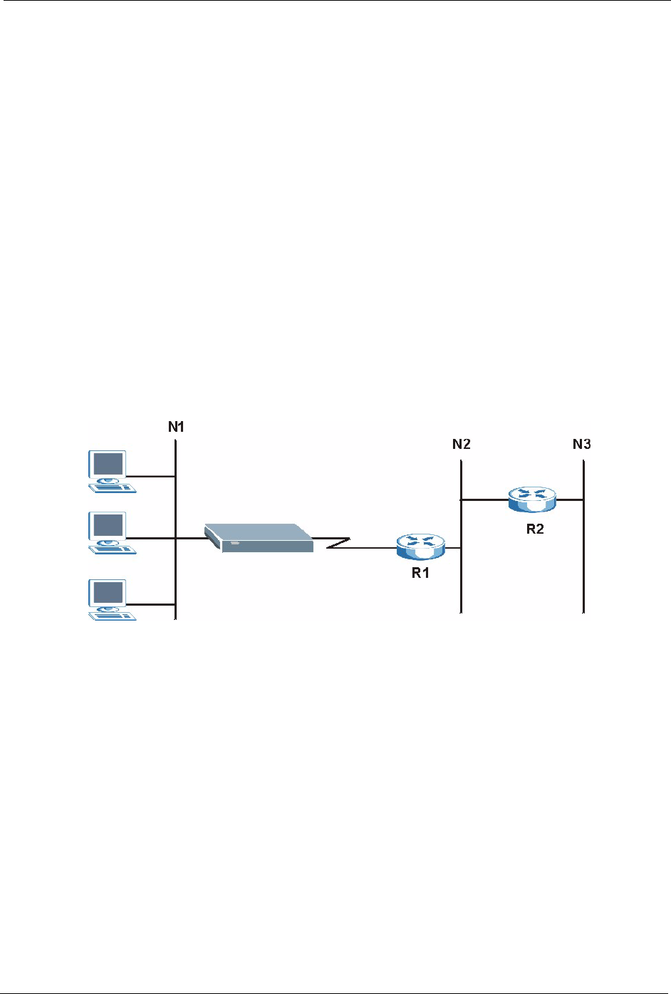
10.1 Static Route Overview
Each remote node specifies only the network to which the gateway is directly connected, and
the Prestige has no knowledge of the networks beyond. For instance, the Prestige knows about
network N2 in the following figure through remote node router R1. However, the Prestige is
unable to route a packet to network N3 because it doesn't know that there is a route through the
same remote node router R1 (via gateway router R2). The static routes are for you to tell the
Prestige about the networks beyond the remote nodes.
Figure 64 Example of Static Routing Topology
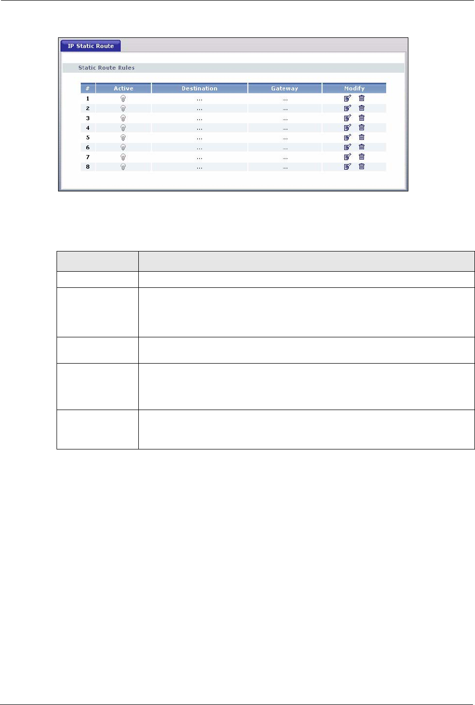
10.2 IP Static Route Screen
Click the IP Static Route link under Management to open the IP Static Route screen. The
following screen displays.
P-320W User’s Guide
116 Chapter 10 Static Route Screens
Figure 65 IP Static Route
The following table describes the labels in this screen.
Table 49 IP Static Route
LABEL DESCRIPTION
#Number of an individual static route.
Active This icon is turned on when this static route is active.
Click the edit icon under Modify and select the Active checkbox in the Static
Route Setup screen to enable the static route. Clear the checkbox to disable this
static route without having to delete the entry.
Destination This parameter specifies the IP network address of the final destination. Routing is
always based on network number.
Gateway This is the IP address of the gateway. The gateway is an immediate neighbor of
your Prestige that will forward the packet to the destination. On the LAN, the
gateway must be a router on the same segment as your Prestige; over the WAN,
the gateway must be the IP address of one of the remote nodes.
Modify Click the edit icon to open the static route setup screen. Modify a static route or
create a new static route in the Static Route Setup screen.
Click the delete icon to remove a static route.
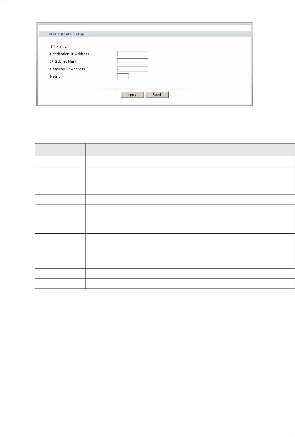
10.2.1 Static Route Setup Screen
To edit a static route, click the edit icon under Modify. The following screen displays. Fill in
the required information for each static route.
P-320W User’s Guide
Chapter 10 Static Route Screens 117
Figure 66 Static Route Setup
The following table describes the labels in this screen.
Table 50 Static Route Setup
LABEL DESCRIPTION
Active This field allows you to activate/deactivate this static route.
Destination IP
Address
This parameter specifies the IP network address of the final destination. Routing is
always based on network number. If you need to specify a route to a single host,
use a subnet mask of 255.255.255.255 in the subnet mask field to force the
network number to be identical to the host ID.
IP Subnet Mask Enter the IP subnet mask here.
Gateway IP
Address
Enter the IP address of the gateway. The gateway is an immediate neighbor of
your Prestige that will forward the packet to the destination. On the LAN, the
gateway must be a router on the same segment as your Prestige; over the WAN,
the gateway must be the IP address of one of the Remote Nodes.
Metric Metric represents the “cost” of transmission for routing purposes. IP routing uses
hop count as the measurement of cost, with a minimum of 1 for directly connected
networks. Enter a number that approximates the cost for this link. The number
need not be precise, but it must be between 1 and 15. In practice, 2 or 3 is usually
a good number.
Apply Click Apply to save your changes back to the Prestige.
Reset Click Reset to start configuring this screen again.

P-320W User’s Guide
118 Chapter 10 Static Route Screens

P-320W User’s Guide
Chapter 11 Remote Management Screens 119
CHAPTER 11
Remote Management Screens
This chapter provides information on the Remote Management screens.
11.1 Remote Management Overview
Remote management allows you to determine which services/protocols can access which
Prestige interface (if any) from which computers.
Note: When you configure remote management to allow management from the WAN,
you still need to configure a firewall rule to allow access. See the firewall
chapters for details on configuring firewall rules.
You may manage your Prestige from a remote location via:
• LAN only • ALL (LAN and WAN)
To disable remote management of a service, select LAN in the corresponding Server Access
field.
11.1.1 Remote Management Limitations
Remote management over LAN or WAN will not work when:
1You have disabled that service in one of the remote management screens.
2The IP address in the Secured Client IP field does not match the client IP address. If it
does not match, the Prestige will disconnect the session immediately.
3There is a firewall rule that blocks it.
11.1.2 Remote Management and NAT
When NAT is enabled:
• Use the Prestige’s WAN IP address when configuring from the WAN.
• Use the Prestige’s LAN IP address when configuring from the LAN.
P-320W User’s Guide
120 Chapter 11 Remote Management Screens
11.1.3 System Timeout
There is a default system management idle timeout of five minutes (three hundred seconds).
The Prestige automatically logs you out if the management session remains idle for longer
than this timeout period. The management session does not time out when a statistics screen is
polling. You can change the timeout period in the System screen
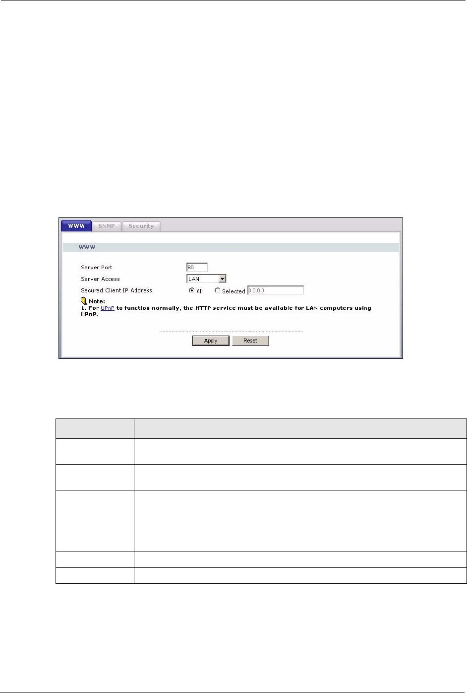
11.2 WWW Screen
To change your Prestige’s World Wide Web settings, click the Remote MGMT link under
Management to display the WWW screen.
Figure 67 WWW Remote Management
The following table describes the labels in this screen.
Table 51 WWW Remote Management
LABEL DESCRIPTION
Server Port You may change the server port number for a service if needed, however you must
use the same port number in order to use that service for remote management.
Server Access Select the interface(s) through which a computer may access the Prestige using
this service.
Secured Client IP
Address
A secured client is a “trusted” computer that is allowed to communicate with the
Prestige using this service.
Select All to allow any computer to access the Prestige using this service.
Choose Selected to just allow the computer with the IP address that you specify to
access the Prestige using this service.
Apply Click Apply to save your changes back to the Prestige.
Reset Click Reset to begin configuring this screen afresh.
P-320W User’s Guide
Chapter 11 Remote Management Screens 121
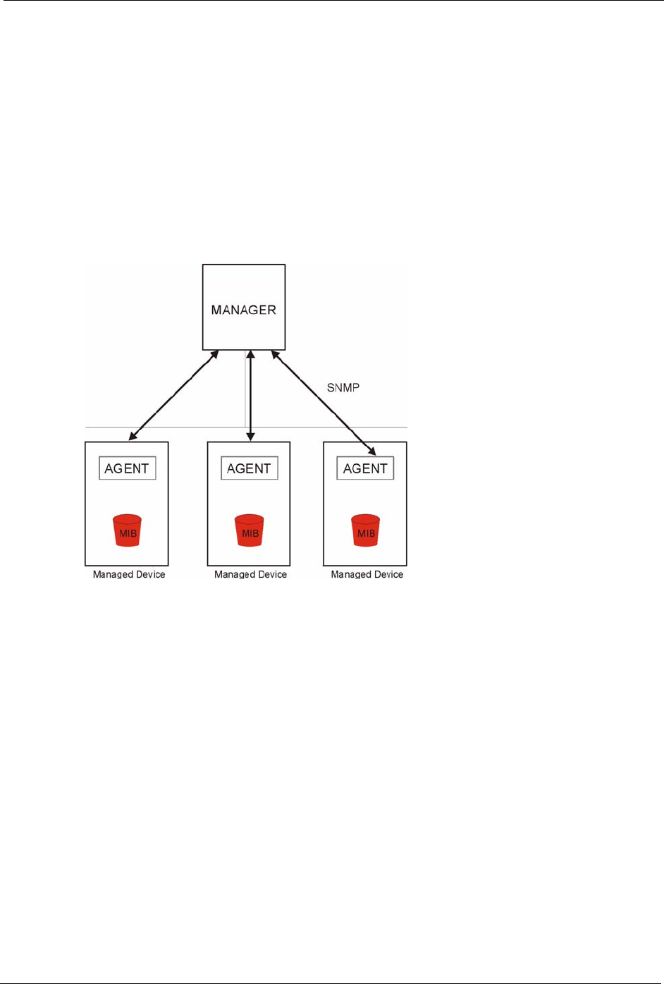
11.3 SNMP
Simple Network Management Protocol (SNMP) is a protocol used for exchanging
management information between network devices. SNMP is a member of the TCP/IP
protocol suite. Your Prestige supports SNMP agent functionality, which allows a manager
station to manage and monitor the Prestige through the network. The Prestige supports SNMP
version one (SNMPv1) and version two (SNMPv2). The next figure illustrates an SNMP
management operation.
Note: SNMP is only available if TCP/IP is configured.
Figure 68 SNMP Management Model
An SNMP managed network consists of two main types of component: agents and a manager.
An agent is a management software module that resides in a managed device (the Prestige).
An agent translates the local management information from the managed device into a form
compatible with SNMP. The manager is the console through which network administrators
perform network management functions. It executes applications that control and monitor
managed devices.
The managed devices contain object variables/managed objects that define each piece of
information to be collected about a device. Examples of variables include such as number of
packets received, node port status etc. A Management Information Base (MIB) is a collection
of managed objects. SNMP allows a manager and agents to communicate for the purpose of
accessing these objects.
SNMP itself is a simple request/response protocol based on the manager/agent model. The
manager issues a request and the agent returns responses using the following protocol
operations:
P-320W User’s Guide
122 Chapter 11 Remote Management Screens
• Get - Allows the manager to retrieve an object variable from the agent.
• GetNext - Allows the manager to retrieve the next object variable from a table or list
within an agent. In SNMPv1, when a manager wants to retrieve all elements of a table
from an agent, it initiates a Get operation, followed by a series of GetNext operations.
• Set - Allows the manager to set values for object variables within an agent.
• Trap - Used by the agent to inform the manager of some events.
11.3.1 Supported MIBs
The Prestige supports MIB II that is defined in RFC-1213 and RFC-1215. The focus of the
MIBs is to let administrators collect statistical data and monitor status and performance.
11.3.2 SNMP Traps
The Prestige will send traps to the SNMP manager when any one of the following events
occurs:
Table 52 SNMP Traps
TRAP # TRAP NAME DESCRIPTION
0coldStart (defined in RFC-1215)A trap is sent after booting (power on).
1warmStart (defined in RFC-1215)A trap is sent after booting (software reboot).
4authenticationFailure (defined in
RFC-1215)
A trap is sent to the manager when receiving any
SNMP get or set requirements with the wrong
community (password).
6whyReboot (defined in ZYXEL-
MIB)
A trap is sent with the reason of restart before
rebooting when the system is going to restart (warm
start).
6a For intentional reboot : A trap is sent with the message "System reboot by
user!" if reboot is done intentionally, (for example,
download new files, CI command "sys reboot", etc.).
6b For fatal error : A trap is sent with the message of the fatal code if the
system reboots because of fatal errors.
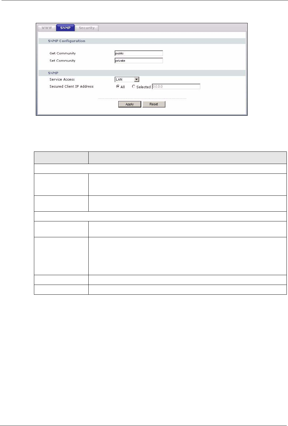
11.4 SNMP Screen
To change your Prestige’s SNMP settings, click the Remote MGMT link under
Management, and the SNMP tab. The screen appears as shown.
P-320W User’s Guide
Chapter 11 Remote Management Screens 123
Figure 69 SNMP Remote Management
The following table describes the labels in this screen.
Table 53 SNMP Remote Management
LABEL DESCRIPTION
SNMP Configuration
Get Community Enter the Get Community, which is the password for the incoming Get and
GetNext requests from the management station. The default is public and allows
all requests.
Set Community Enter the Set community, which is the password for incoming Set requests
from the management station. The default is public and allows all requests.
SNMP
Service Access Select the interface(s) through which a computer may access the Prestige using
this service.
Secured Client IP
Address
A secured client is a “trusted” computer that is allowed to communicate with the
Prestige using this service.
Select All to allow any computer to access the Prestige using this service.
Choose Selected to just allow the computer with the IP address that you specify
to access the Prestige using this service.
Apply Click Apply to save your changes back to the Prestige.
Reset Click Reset to begin configuring this screen afresh.
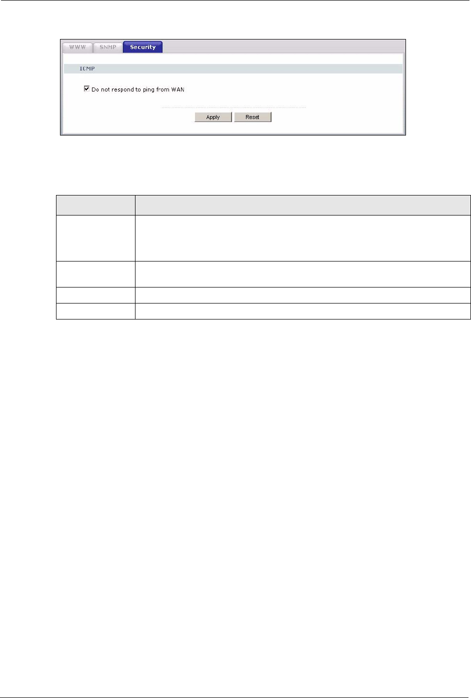
11.5 Security Screen
To change your Prestige’s security settings, click the Remote MGMT link under
Management and the Security tab. The screen appears as shown.
If an outside user attempts to probe an unsupported port on your Prestige, an ICMP response
packet is automatically returned. This allows the outside user to know the Prestige exists.
Your Prestige supports anti-probing, which prevents the ICMP response packet from being
sent. This keeps outsiders from discovering your Prestige when unsupported ports are probed.
P-320W User’s Guide
124 Chapter 11 Remote Management Screens
Figure 70 Security Remote Management
The following table describes the labels in this screen.
Table 54 Security Remote Management
LABEL DESCRIPTION
ICMP Internet Control Message Protocol is a message control and error-reporting
protocol between a host server and a gateway to the Internet. ICMP uses Internet
Protocol (IP) datagrams, but the messages are processed by the TCP/IP software
and directly apparent to the application user.
Do not respond to
ping from WAN
The Prestige will not respond to any incoming WAN Ping requests when the check
box is selected.
Apply Click Apply to save your changes back to the Prestige.
Reset Click Reset to begin configuring this screen afresh.

P-320W User’s Guide
Chapter 12 UPnP 125
CHAPTER 12
UPNP
This chapter introduces the Universal Plug and Play feature.
12.1 Universal Plug and Play Overview
Universal Plug and Play (UPnP) is a distributed, open networking standard that uses TCP/IP
for simple peer-to-peer network connectivity between devices. A UPnP device can
dynamically join a network, obtain an IP address, convey its capabilities and learn about other
devices on the network. In turn, a device can leave a network smoothly and automatically
when it is no longer in use.
12.1.1 How Do I Know If I'm Using UPnP?
UPnP hardware is identified as an icon in the Network Connections folder (Windows XP).
Each UPnP compatible device installed on your network will appear as a separate icon.
Selecting the icon of a UPnP device will allow you to access the information and properties of
that device.
12.1.2 NAT Traversal
UPnP NAT traversal automates the process of allowing an application to operate through
NAT. UPnP network devices can automatically configure network addressing, announce their
presence in the network to other UPnP devices and enable exchange of simple product and
service descriptions. NAT traversal allows the following:
1Dynamic port mapping
2Learning public IP addresses
3Assigning lease times to mappings
Windows Messenger is an example of an application that supports NAT traversal and UPnP.
See the SUA/NAT chapter for further information about NAT.
12.1.3 Cautions with UPnP
The automated nature of NAT traversal applications in establishing their own services and
opening firewall ports may present network security issues. Network information and
configuration may also be obtained and modified by users in some network environments.
P-320W User’s Guide
126 Chapter 12 UPnP
All UPnP-enabled devices may communicate freely with each other without additional
configuration. Disable UPnP if this is not your intention.
12.2 UPnP and ZyXEL
ZyXEL has achieved UPnP certification from the Universal Plug and Play Forum Creates
UPnP™ Implementers Corp. (UIC). ZyXEL's UPnP implementation supports IGD 1.0
(Internet Gateway Device). At the time of writing ZyXEL's UPnP implementation supports
Windows Messenger 4.6 and 4.7 while Windows Messenger 5.0 and Xbox are still being
tested.
UPnP broadcasts are only allowed on the LAN.
Please see later in this User’s Guide for examples of installing UPnP in Windows XP and
Windows Me as well as an example of using UPnP in Windows.
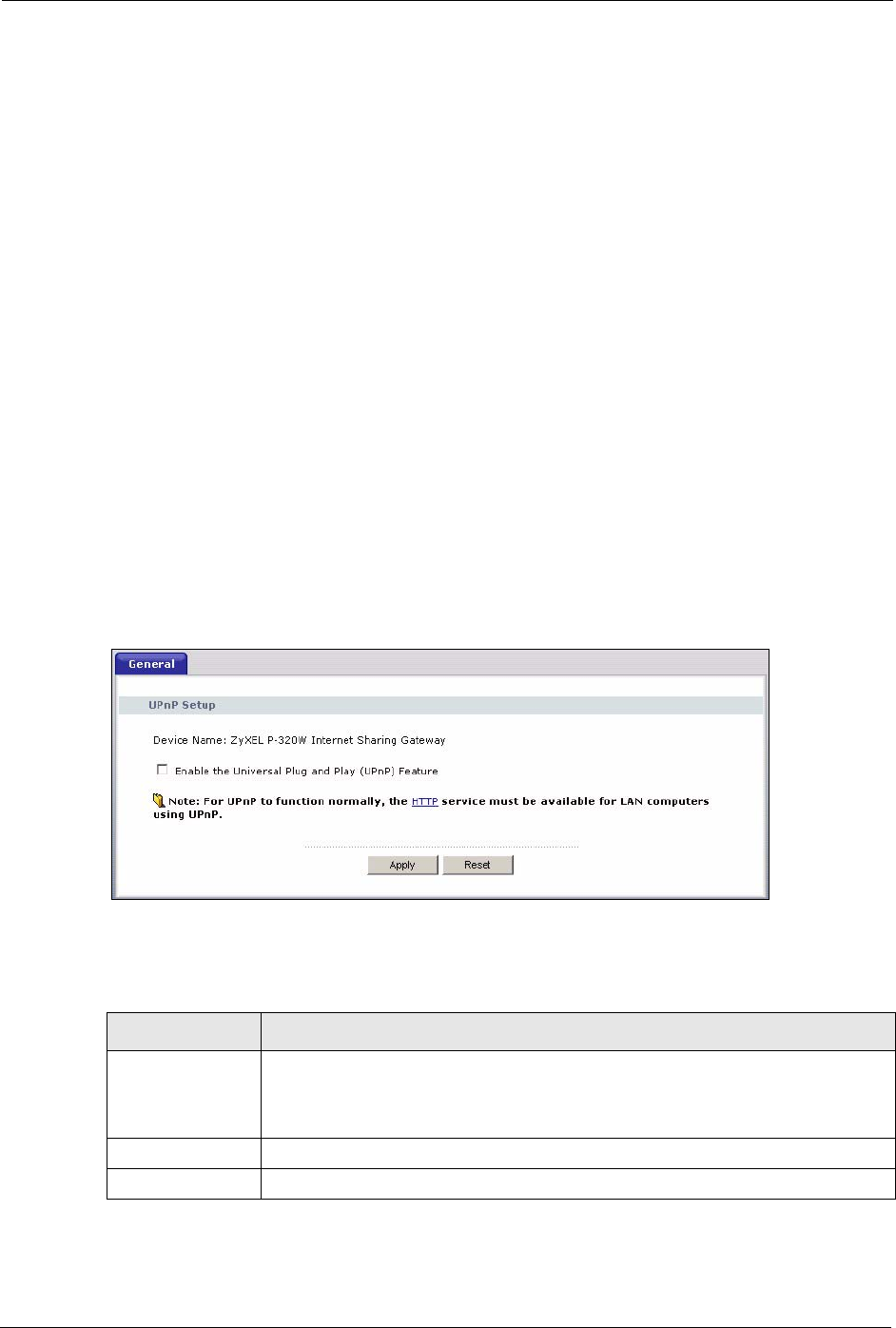
12.3 UPnP Screen
Click the UPnP link under Management to display the UPnP screen.
Figure 71 Configuring UPnP
The following table describes the labels in this screen.
Table 55 Configuring UPnP
LABEL DESCRIPTION
Enable the
Universal Plug and
Play (UPnP)
feature
Select this checkbox to activate UPnP. Be aware that anyone could use a UPnP
application to open the web configurator's login screen without entering the
Prestige's IP address (although you must still enter the password to access the
web configurator).
Apply Click Apply to save your changes back to the Prestige.
Reset Click Reset to begin configuring this screen afresh.
P-320W User’s Guide
Chapter 12 UPnP 127
12.4 Installing UPnP in Windows Example
This section shows how to install UPnP in Windows Me and Windows XP.
12.4.1 Installing UPnP in Windows Me
Follow the steps below to install UPnP in Windows Me.
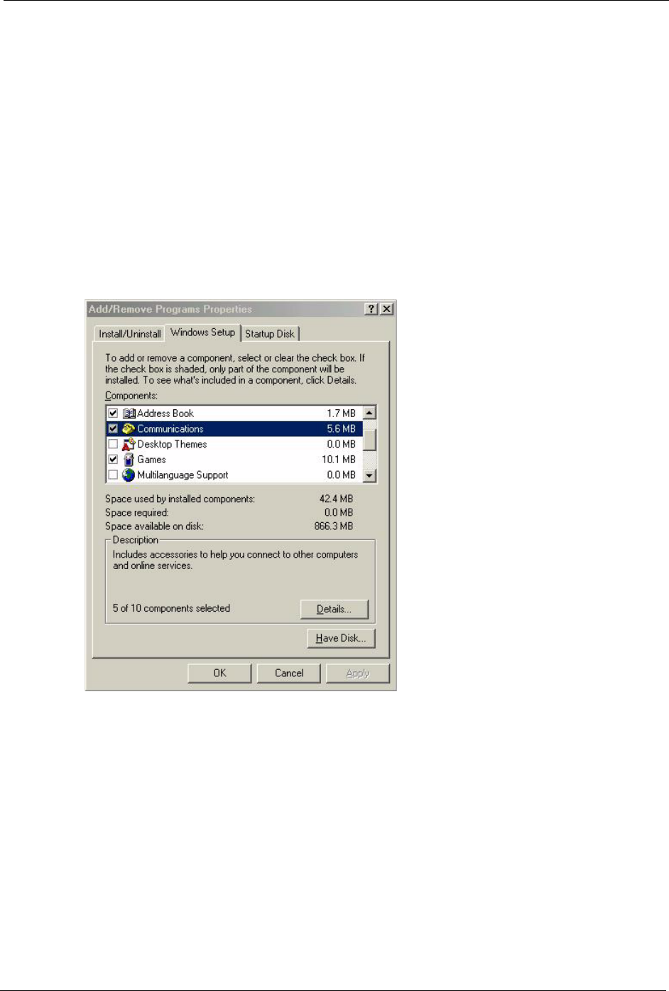
1Click Start and Control Panel. Double-click Add/Remove Programs.
2Click on the Windows Setup tab and select Communication in the Components
selection box. Click Details.
Figure 72 Add/Remove Programs: Windows Setup: Communication
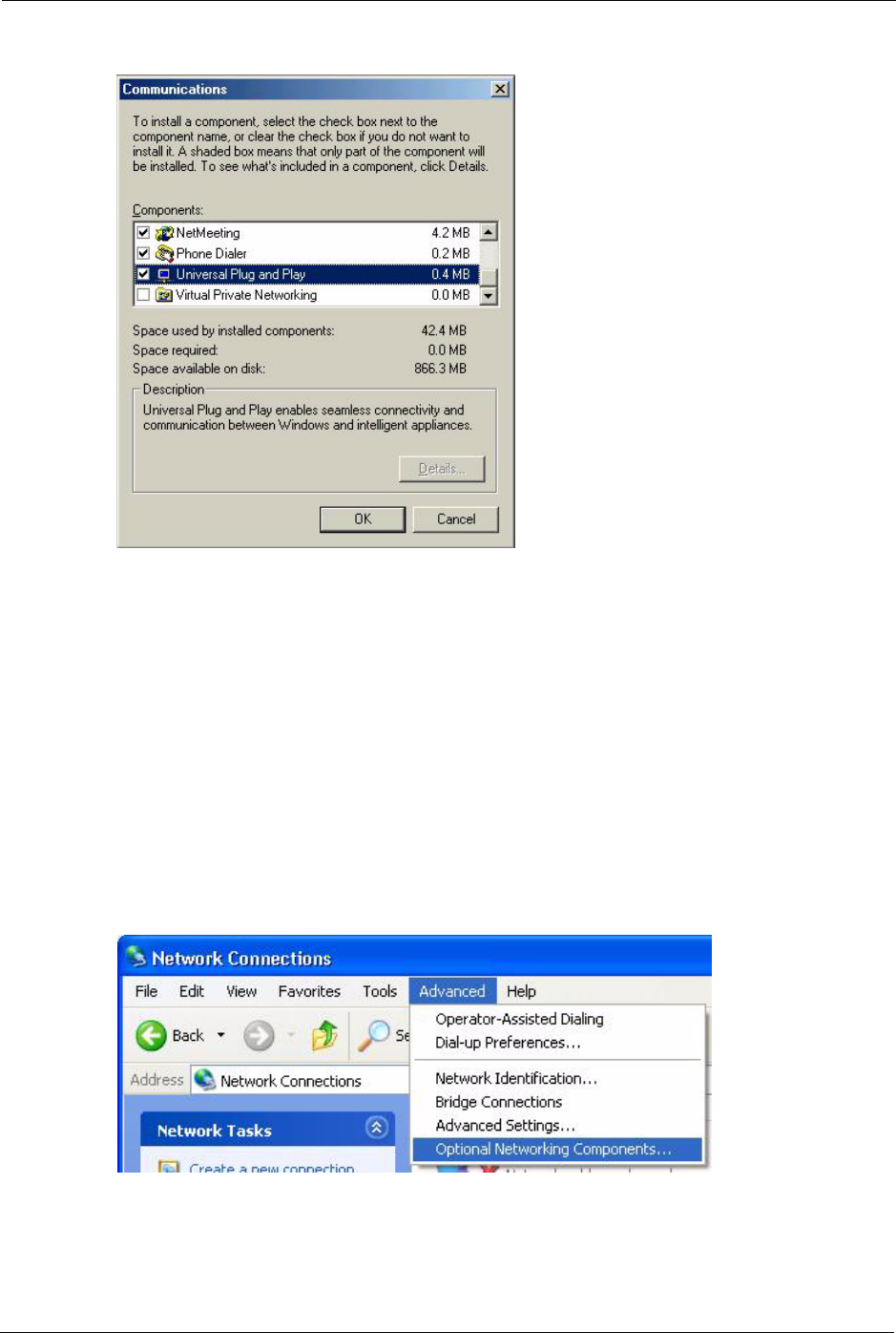
3In the Communications window, select the Universal Plug and Play check box in the
Components selection box.
P-320W User’s Guide
128 Chapter 12 UPnP
Figure 73 Add/Remove Programs: Windows Setup: Communication: Components
4Click OK to go back to the Add/Remove Programs Properties window and click Next.
5Restart the computer when prompted.
12.4.2 Installing UPnP in Windows XP
Follow the steps below to install the UPnP in Windows XP.
1Click Start and Control Panel.
2Double-click Network Connections.
3In the Network Connections window, click Advanced in the main menu and select
Optional Networking Components ….
Figure 74 Network Connections
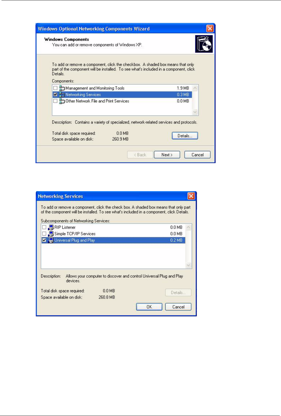
4The Windows Optional Networking Components Wizard window displays. Select
Networking Service in the Components selection box and click Details.
P-320W User’s Guide
Chapter 12 UPnP 129
Figure 75 Windows Optional Networking Components Wizard
5In the Networking Services window, select the Universal Plug and Play check box.
Figure 76 Networking Services
Click OK to go back to the Windows Optional Networking Component Wizard window
and click Next.
12.5 Using UPnP in Windows XP Example
This section shows you how to use the UPnP feature in Windows XP. You must already have
UPnP installed in Windows XP and UPnP activated on the ZyXEL device.
P-320W User’s Guide
130 Chapter 12 UPnP
Make sure the computer is connected to a LAN port of the ZyXEL device. Turn on your
computer and the ZyXEL device.
12.5.1 Auto-discover Your UPnP-enabled Network Device
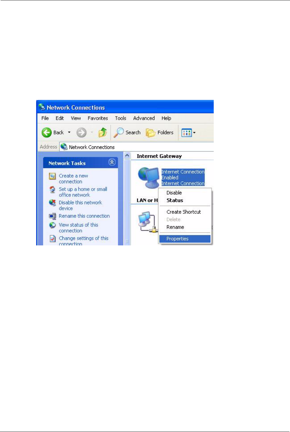
1Click Start and Control Panel. Double-click Network Connections. An icon displays
under Internet Gateway.
2Right-click the icon and select Properties.
Figure 77 Network Connections
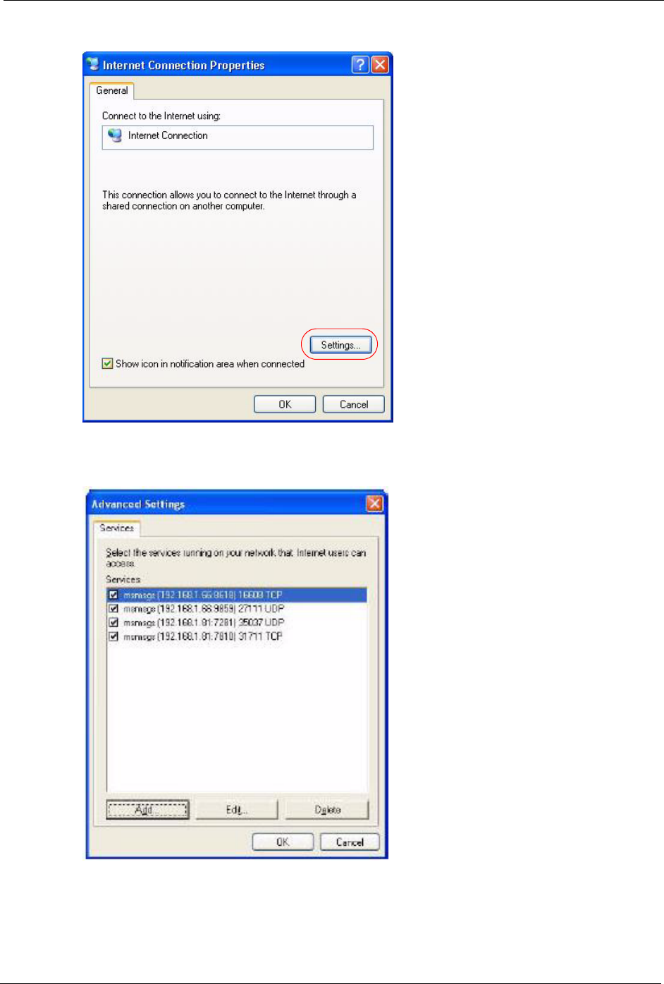
3In the Internet Connection Properties window, click Settings to see the port mappings
there were automatically created.
P-320W User’s Guide
Chapter 12 UPnP 131
Figure 78 Internet Connection Properties
4You may edit or delete the port mappings or click Add to manually add port mappings.
Figure 79 Internet Connection Properties: Advanced Settings
P-320W User’s Guide
132 Chapter 12 UPnP
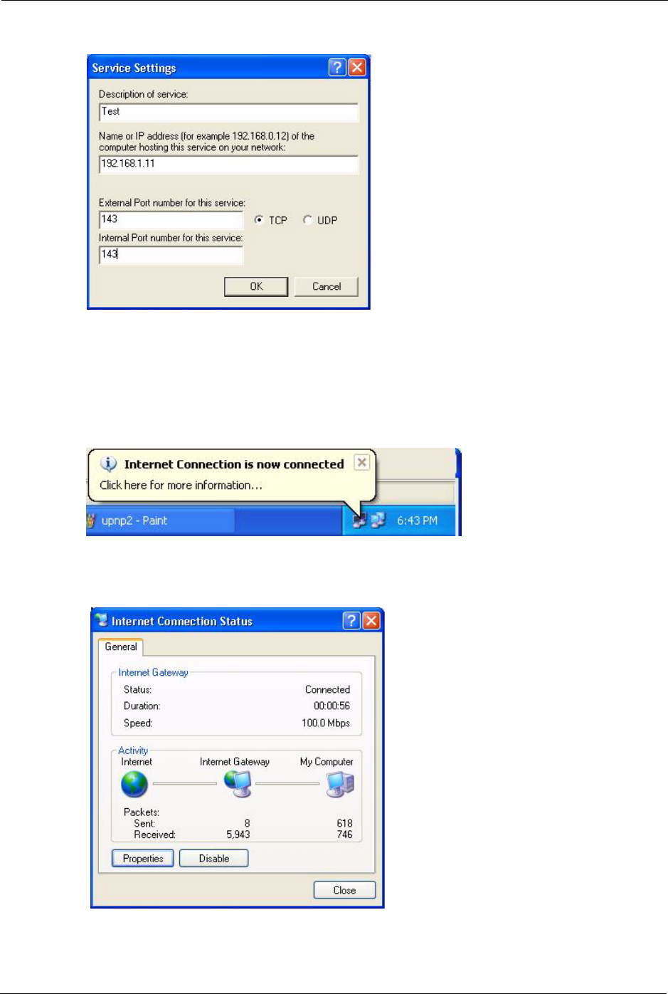
Figure 80 Internet Connection Properties: Advanced Settings: Add
5When the UPnP-enabled device is disconnected from your computer, all port mappings
will be deleted automatically.
6Select Show icon in notification area when connected option and click OK. An icon
displays in the system tray.
Figure 81 System Tray Icon
7Double-click on the icon to display your current Internet connection status.
Figure 82 Internet Connection Status
P-320W User’s Guide
Chapter 12 UPnP 133
12.5.2 Web Configurator Easy Access
With UPnP, you can access the web-based configurator on the ZyXEL device without finding
out the IP address of the ZyXEL device first. This is helpful if you do not know the IP address
of the ZyXEL device.
Follow the steps below to access the web configurator.
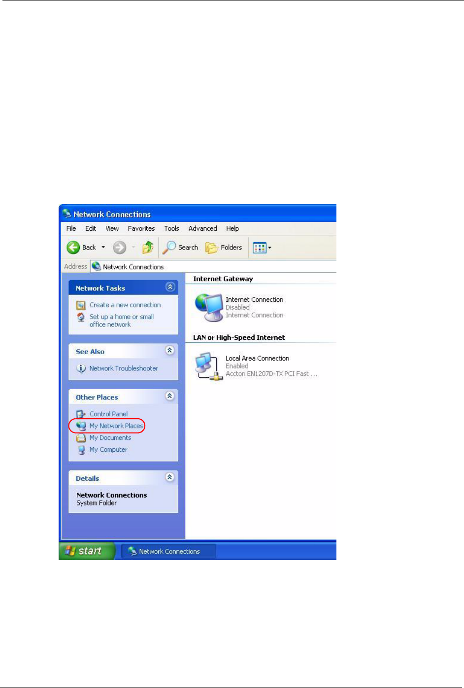
1Click Start and then Control Panel.
2Double-click Network Connections.
3Select My Network Places under Other Places.
Figure 83 Network Connections
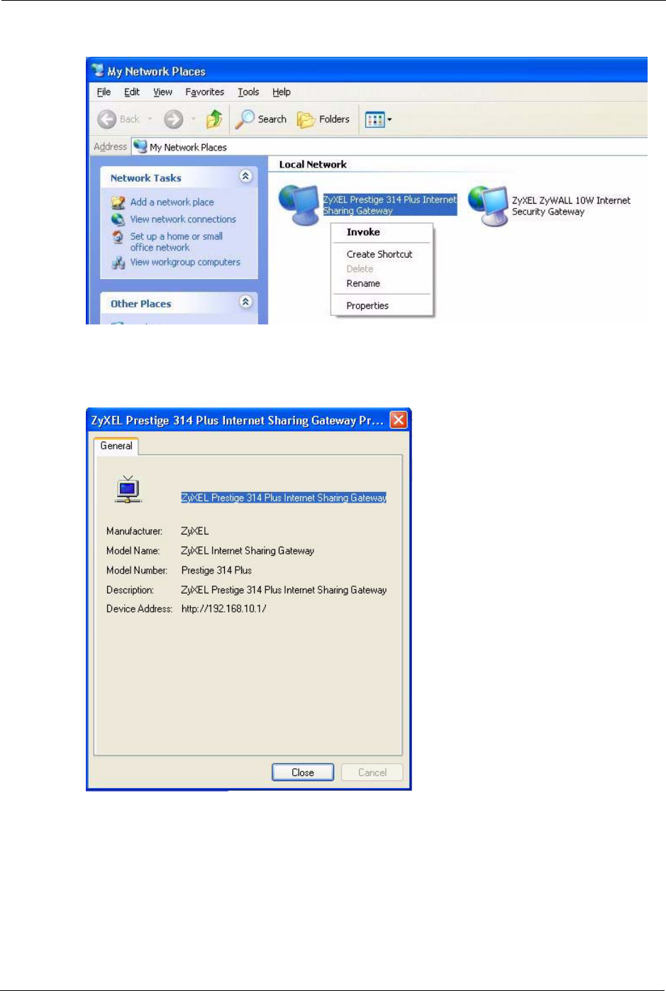
4An icon with the description for each UPnP-enabled device displays under Local
Network.
5Right-click on the icon for your Prestige and select Invoke. The web configurator login
screen displays.
P-320W User’s Guide
134 Chapter 12 UPnP
Figure 84 Network Connections: My Network Places
6Right-click on the icon for your Prestige and select Properties. A properties window
displays with basic information about the Prestige.
Figure 85 Network Connections: My Network Places: Properties: Example
P-320W User’s Guide
Chapter 13 System 135
CHAPTER 13
System
This chapter provides information on the System screens.
13.1 System Overview
See the Wizard Setup chapter for more information on the next few screens.
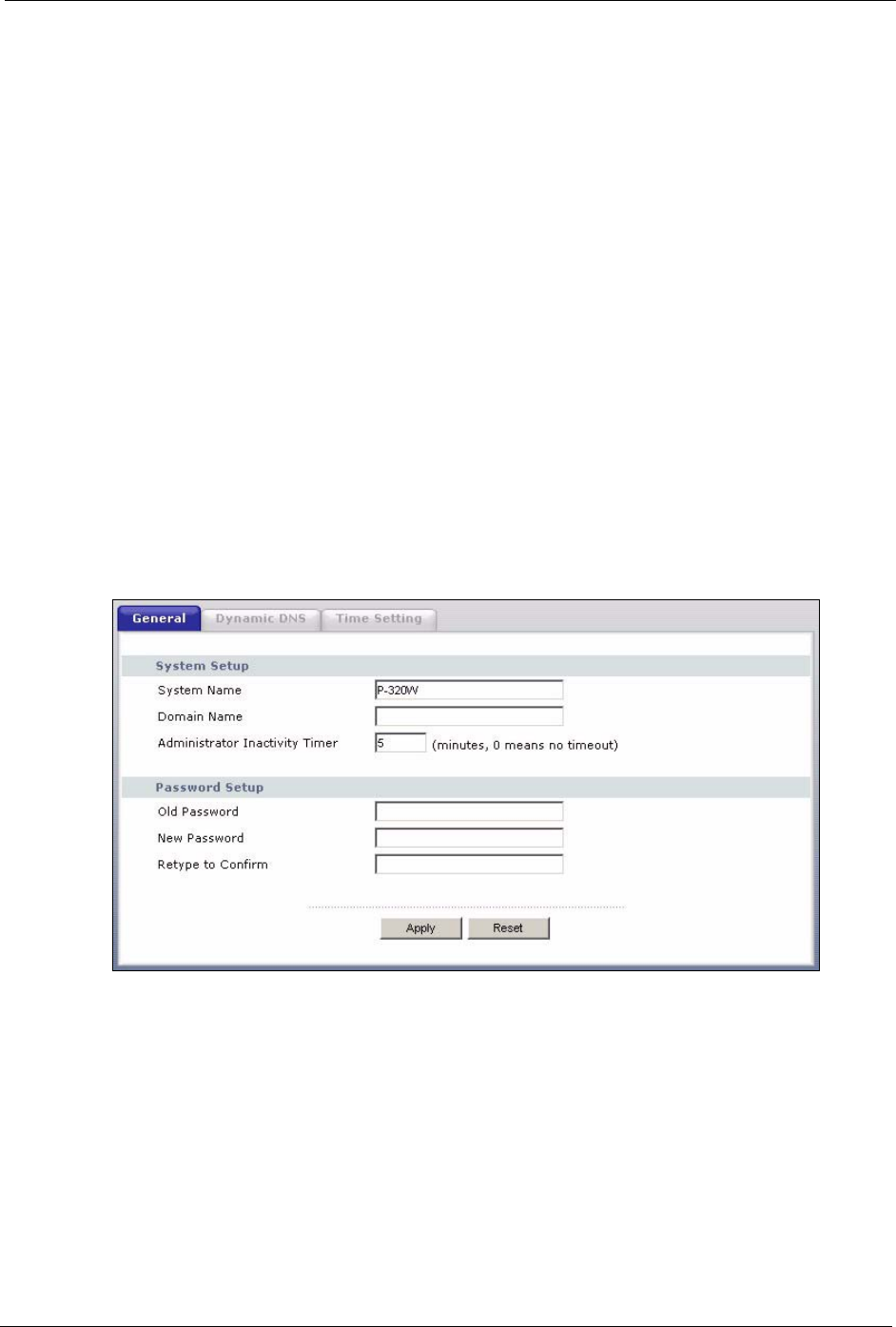
13.2 General Screen
Click the System link under Maintenance and the General tab. The following screen
displays.
Figure 86 System General

P-320W User’s Guide
136 Chapter 13 System
The following table describes the labels in this screen.
Table 56 System General
LABEL DESCRIPTION
System Name System Name is a unique name to identify the Prestige in an Ethernet network.. It
is recommended you enter your computer’s “Computer name” in this field (see the
Wizard Setup chapter for how to find your computer’s name).
This name can be up to 30 alphanumeric characters long. Spaces are not
allowed, but dashes “-” and underscores "_" are accepted.
Domain Name Enter the domain name (if you know it) here. If you leave this field blank, the ISP
may assign a domain name via DHCP.
The domain name entered by you is given priority over the ISP assigned domain
name.
Administrator
Inactivity Timer
Type how many minutes a management session (either via the web configurator
or SMT) can be left idle before the session times out. The default is 5 minutes.
After it times out you have to log in with your password again. Very long idle
timeouts may have security risks. A value of "0" means a management session
never times out, no matter how long it has been left idle (not recommended).
Password Setup Change your Prestige’s password (recommended) using the fields as shown.
Old Password Type the default password or the existing password you use to access the system
in this field.
New Password Type your new system password (up to 30 characters). Note that as you type a
password, the screen displays an asterisk (*) for each character you type.
Retype to Confirm Type the new password again in this field.
Apply Click Apply to save your changes back to the Prestige.
Reset Click Reset to begin configuring this screen afresh.
13.3 Dynamic DNS
Dynamic DNS allows you to update your current dynamic IP address with one or many
dynamic DNS services so that anyone can contact you (in NetMeeting, CU-SeeMe, etc.). You
can also access your FTP server or Web site on your own computer using a domain name (for
instance myhost.dhs.org, where myhost is a name of your choice) that will never change
instead of using an IP address that changes each time you reconnect. Your friends or relatives
will always be able to call you even if they don't know your IP address.
First of all, you need to have registered a dynamic DNS account with www.dyndns.org. This is
for people with a dynamic IP from their ISP or DHCP server that would still like to have a
domain name. The Dynamic DNS service provider will give you a password or key.
13.3.1 DynDNS Wildcard
Enabling the wildcard feature for your host causes *.yourhost.dyndns.org to be aliased to the
same IP address as yourhost.dyndns.org. This feature is useful if you want to be able to use,
for example, www.yourhost.dyndns.org and still reach your hostname.
Note: If you have a private WAN IP address, then you cannot use Dynamic DNS.
P-320W User’s Guide
Chapter 13 System 137
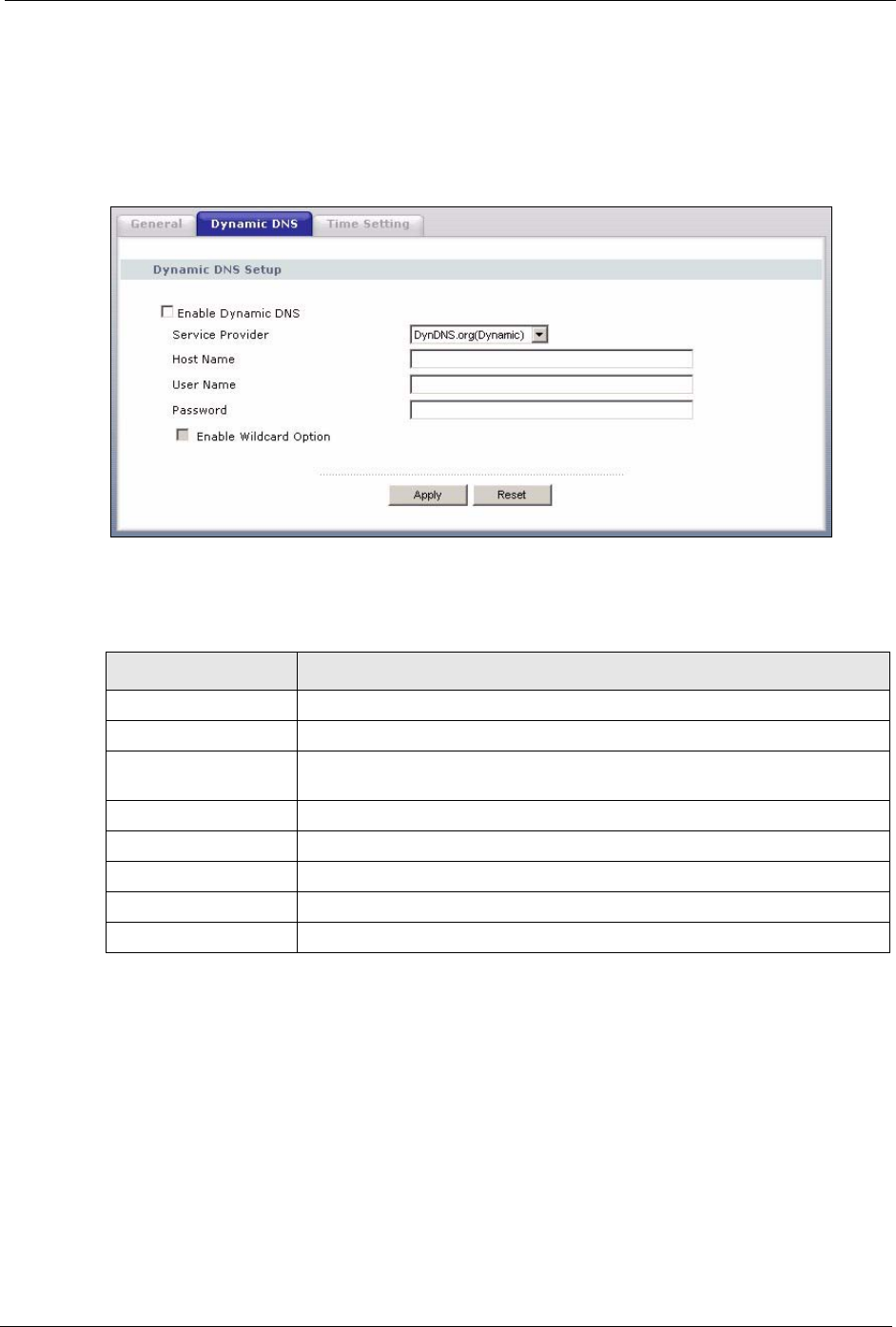
13.4 Dynamic DNS Screen
To change your Prestige’s DDNS, click the System link under Maintenance and the
Dynamic DNS tab. The screen appears as shown.
Figure 87 Dynamic DNS
The following table describes the labels in this screen.
Table 57 Dynamic DNS
LABEL DESCRIPTION
Enable Dynamic DNS Select this check box to use dynamic DNS.
Service Provider Select the name of your Dynamic DNS service provider.
Host Name Enter a host namesin the feld provided. You can specify up to two host
names in the field separated by a comma (",").
User Name Enter your user name.
Password Enter the password assigned to you.
Enable Wildcard Option Select the check box to enable DynDNS Wildcard.
Apply Click Apply to save your changes back to the Prestige.
Reset Click Reset to begin configuring this screen afresh.
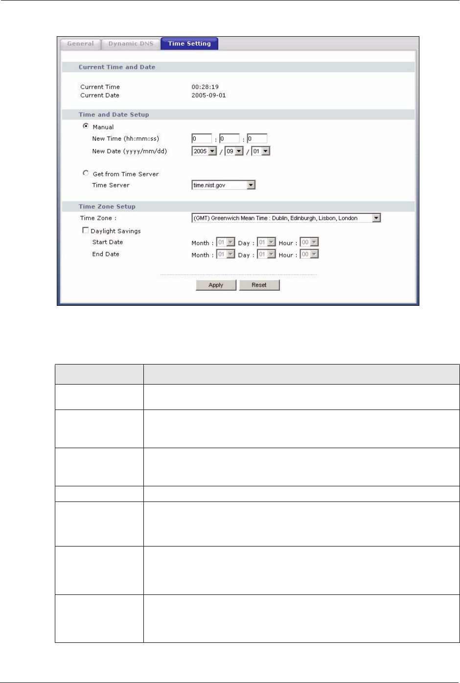
13.5 Time Setting Screen
To change your Prestige’s time and date, click the System link under Maintenance and the
Time Setting tab. The screen appears as shown. Use this screen to configure the Prestige’s
time based on your local time zone.
P-320W User’s Guide
138 Chapter 13 System
Figure 88 Time Setting
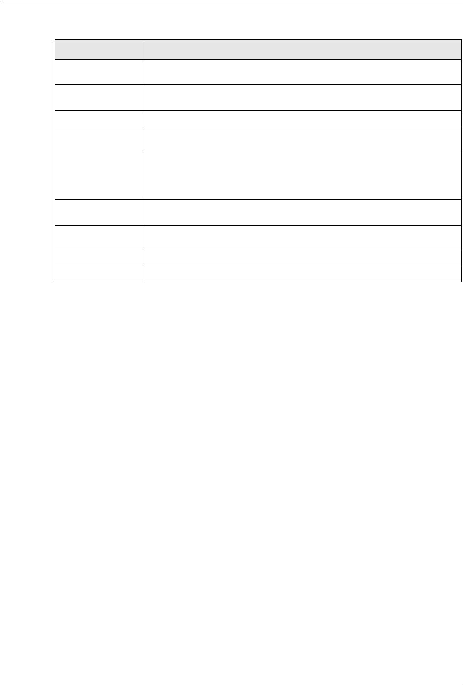
The following table describes the labels in this screen.
Table 58 Time Setting
LABEL DESCRIPTION
Current Time and
Date
Current Time This field displays the time of your Prestige.
Each time you reload this page, the Prestige synchronizes the time with the time
server.
Current Date This field displays the date of your Prestige.
Each time you reload this page, the Prestige synchronizes the date with the time
server.
Time and Date Setup
Manual Select this radio button to enter the time and date manually. If you configure a
new time and date, Time Zone and Daylight Saving at the same time, the new
time and date you entered has priority and the Time Zone and Daylight Saving
settings do not affect it.
New Time
(hh:mm:ss)
This field displays the last updated time from the time server or the last time
configured manually.
When you set Time and Date Setup to Manual, enter the new time in this field
and then click Apply.
New Date
(yyyy-mm-dd)
This field displays the last updated date from the time server or the last date
configured manually.
When you set Time and Date Setup to Manual, enter the new date in this field
and then click Apply.
P-320W User’s Guide
Chapter 13 System 139
Get from Time
Server
Select this radio button to have the Prestige get the time and date from the time
server you specified below.
Time Server Select the URL of your time server. Check with your ISP/network administrator if
you are unsure of this information.
Time Zone Setup
Time Zone Choose the time zone of your location. This will set the time difference between
your time zone and Greenwich Mean Time (GMT).
Daylight Savings Daylight saving is a period from late spring to early fall when many countries set
their clocks ahead of normal local time by one hour to give more daytime light in
the evening.
Select this option if you use Daylight Saving Time.
Start Date Configure the day and time when Daylight Saving Time starts if you selected
Daylight Savings. The Hour field uses the 24 hour format.
End Date Configure the day and time when Daylight Saving Time ends if you selected
Daylight Savings. The Hour field uses the 24 hour format.
Apply Click Apply to save your changes back to the Prestige.
Reset Click Reset to begin configuring this screen afresh.
Table 58 Time Setting
LABEL DESCRIPTION

P-320W User’s Guide
140 Chapter 13 System