ZyXEL Communications P320W 802.11g Wireless Firewall Router User Manual ZyBook
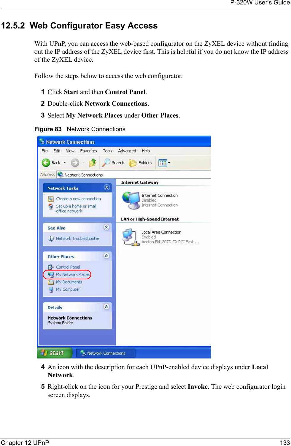
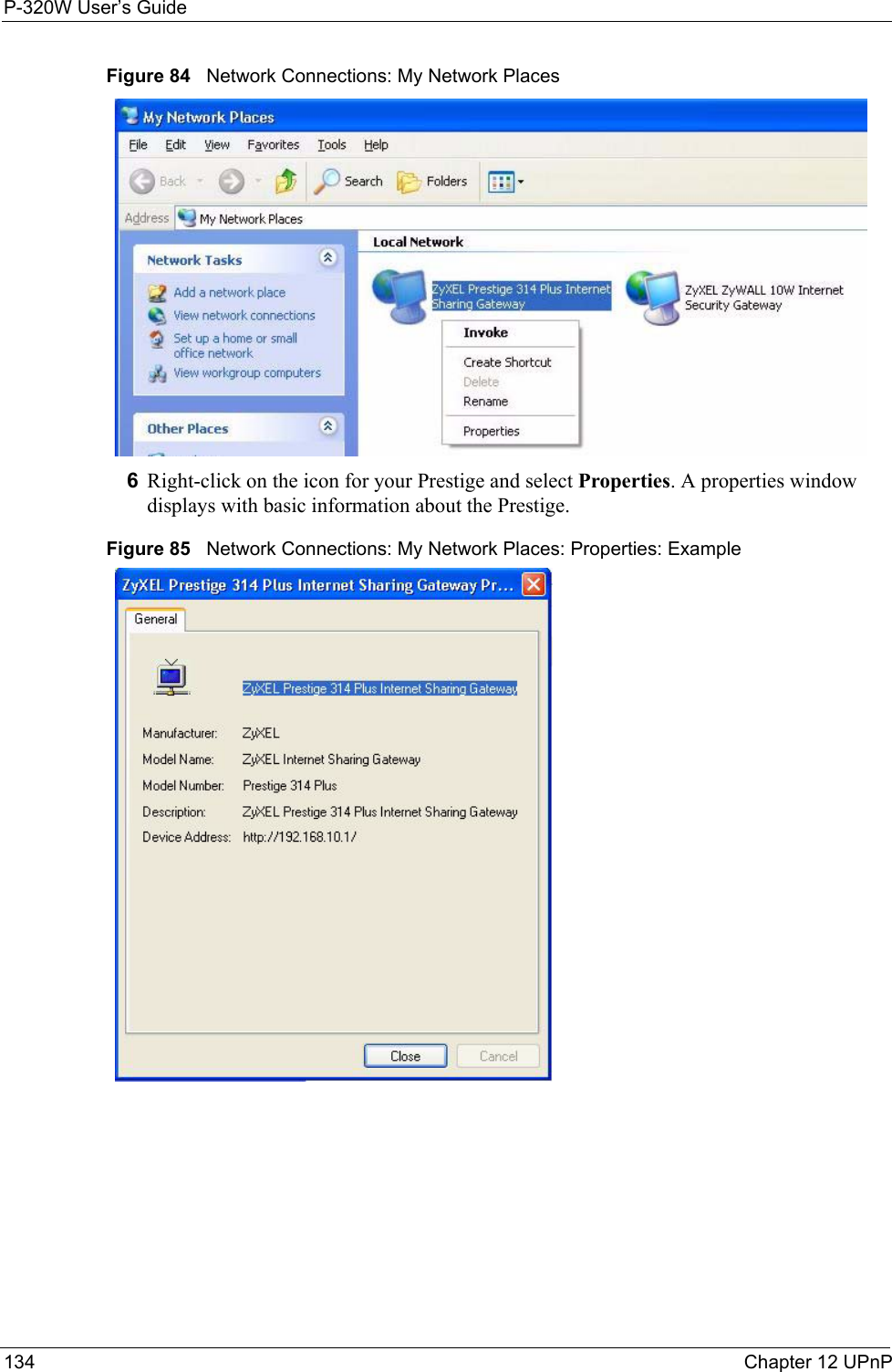
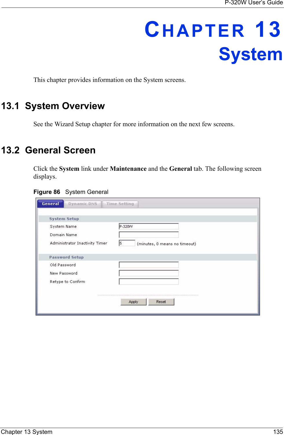
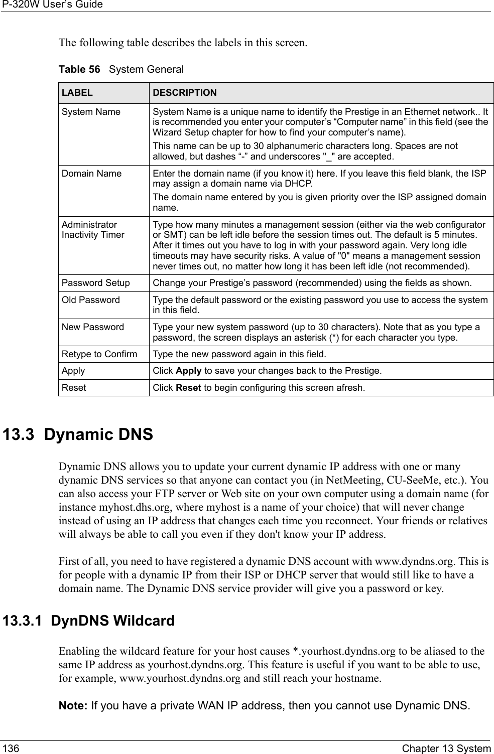
ZyXEL Communications Corporation 802.11g Wireless Firewall Router ZyBook
Contents
- 1. Users Manual 1
- 2. Users Manual 2
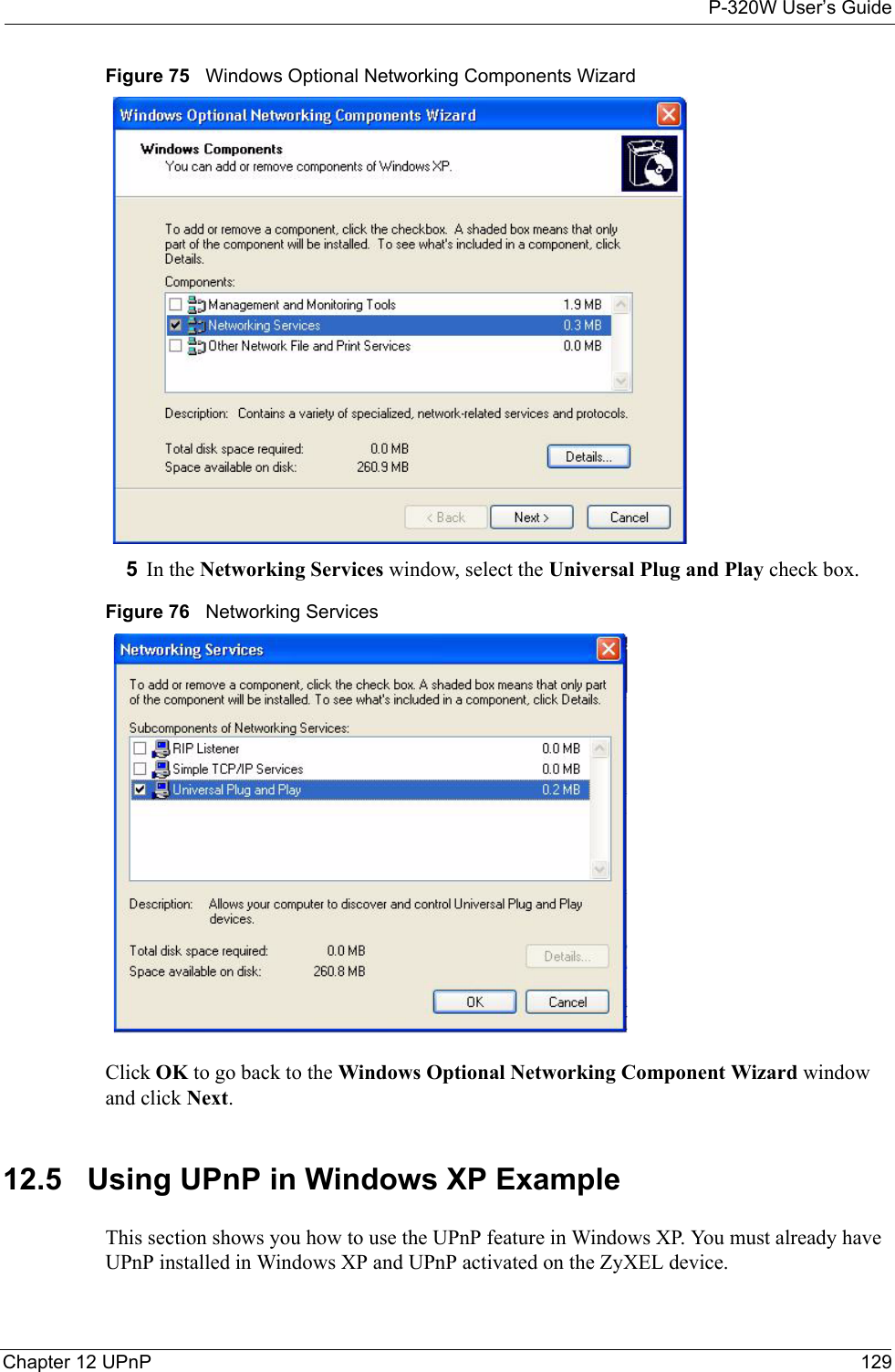
- 3. Users Manual 3
- 4. Users Manual 4
- 5. Users Manual 5
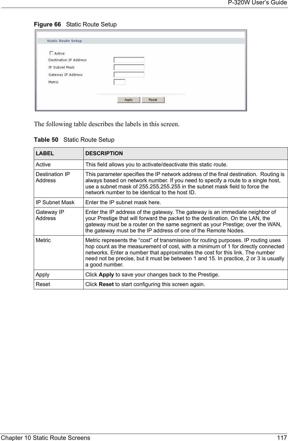
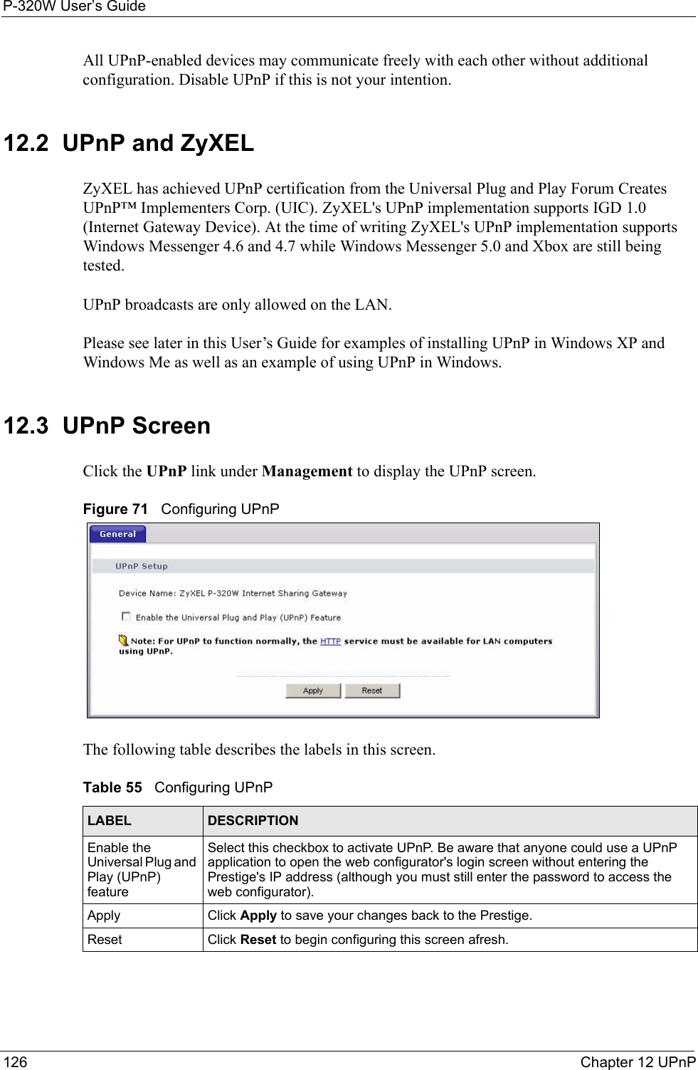
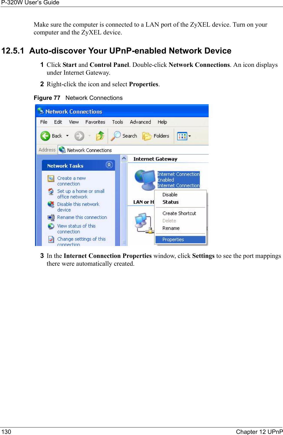
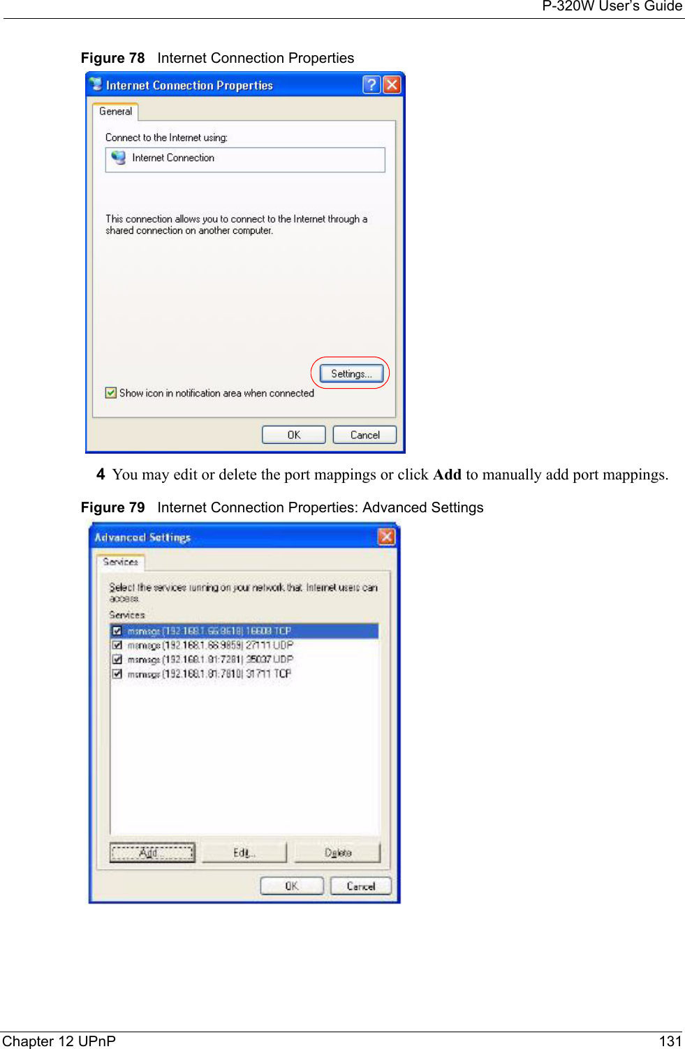
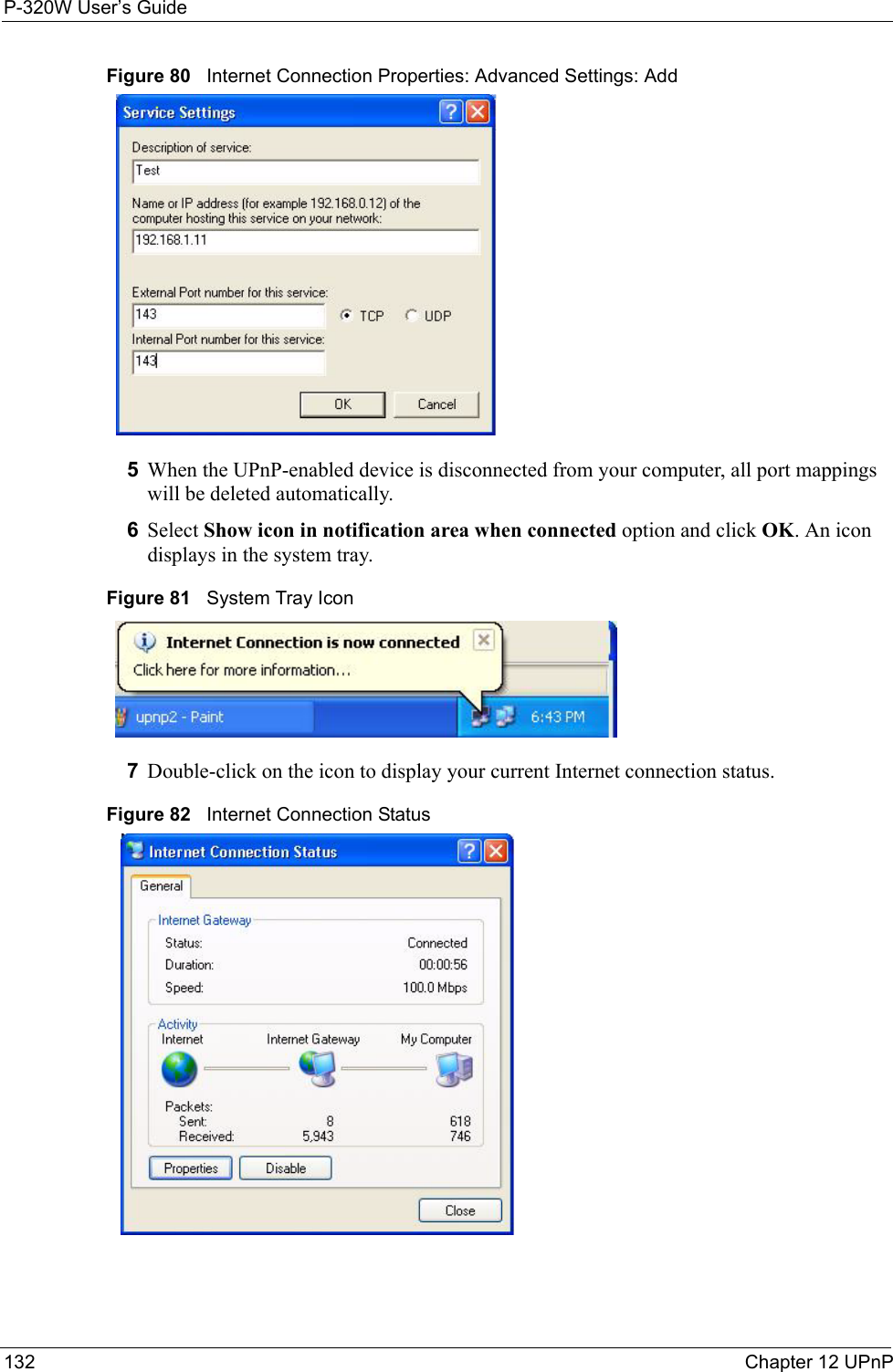
Users Manual 3