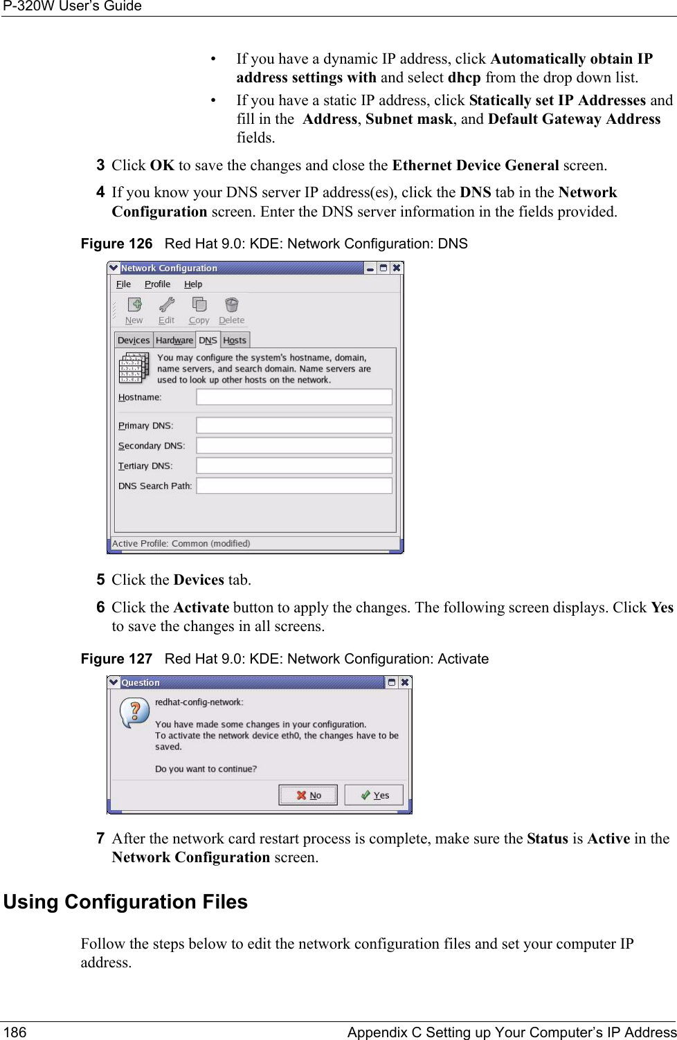
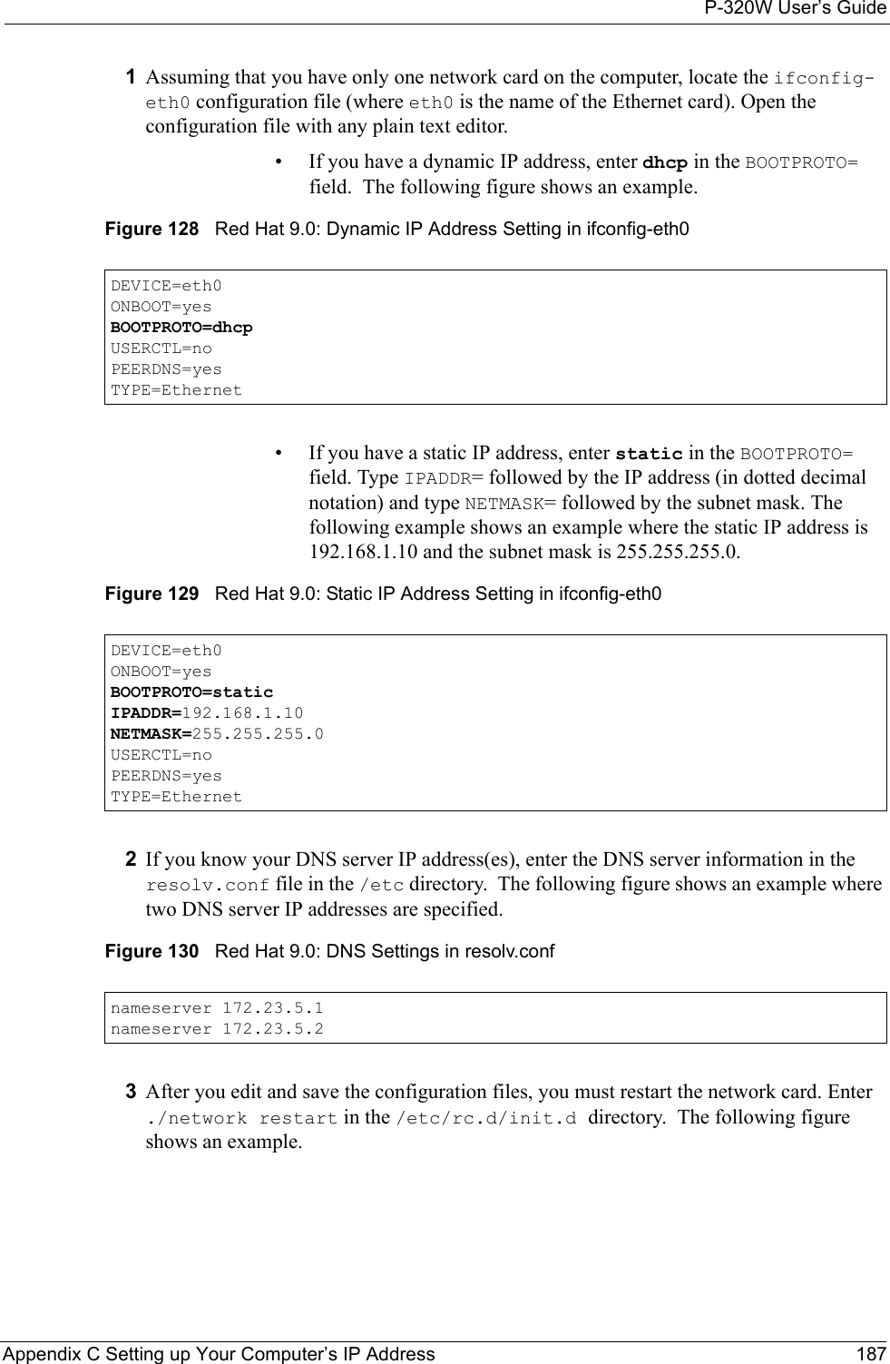
ZyXEL Communications P320W 802.11g Wireless Firewall Router User Manual ZyBook
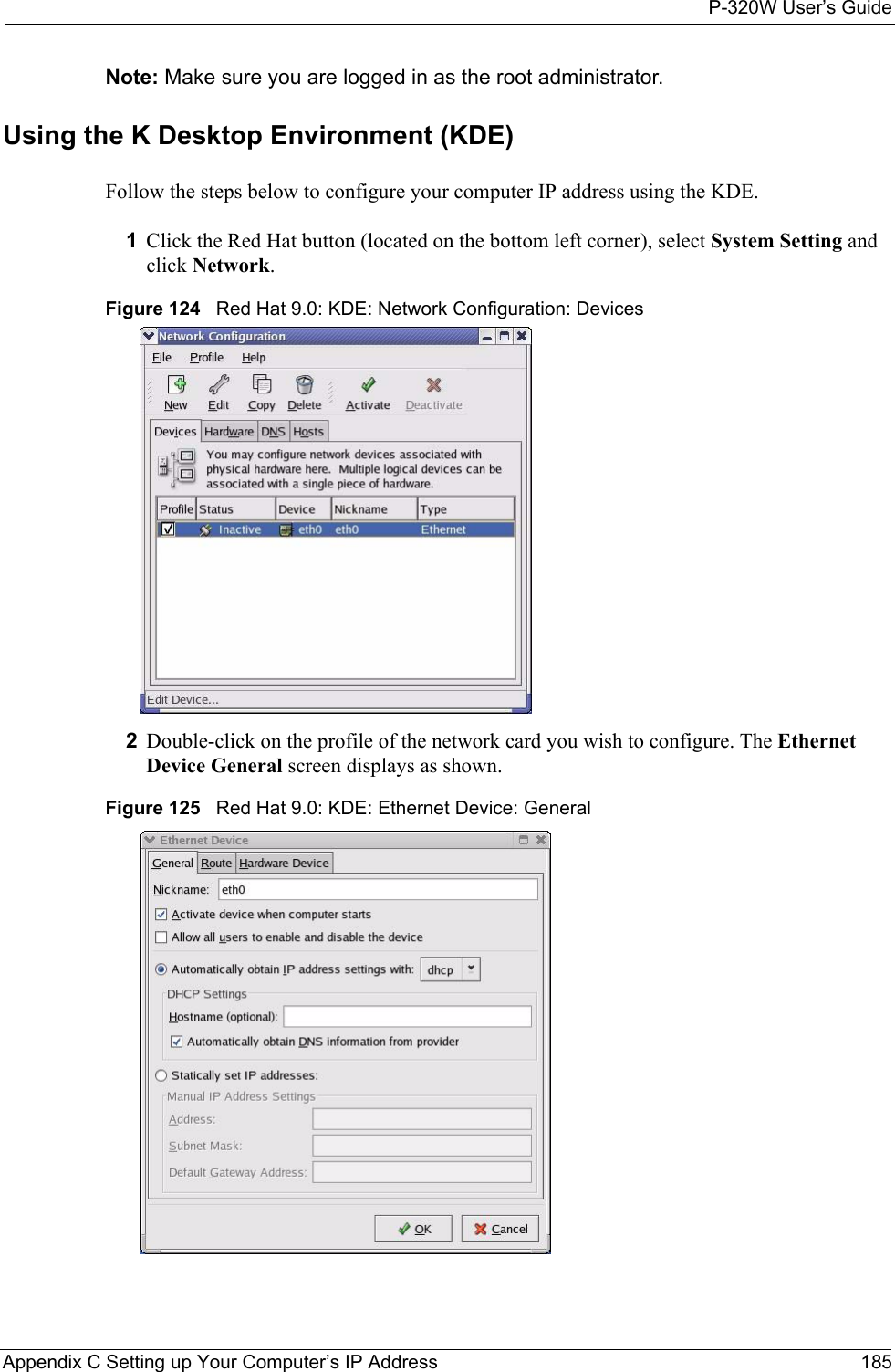
ZyXEL Communications Corporation 802.11g Wireless Firewall Router ZyBook
Contents
- 1. Users Manual 1
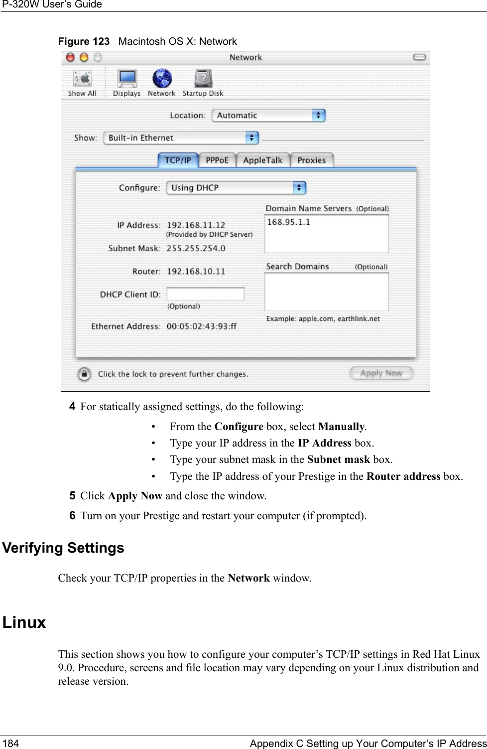
- 2. Users Manual 2
- 3. Users Manual 3
- 4. Users Manual 4
- 5. Users Manual 5
Users Manual 5
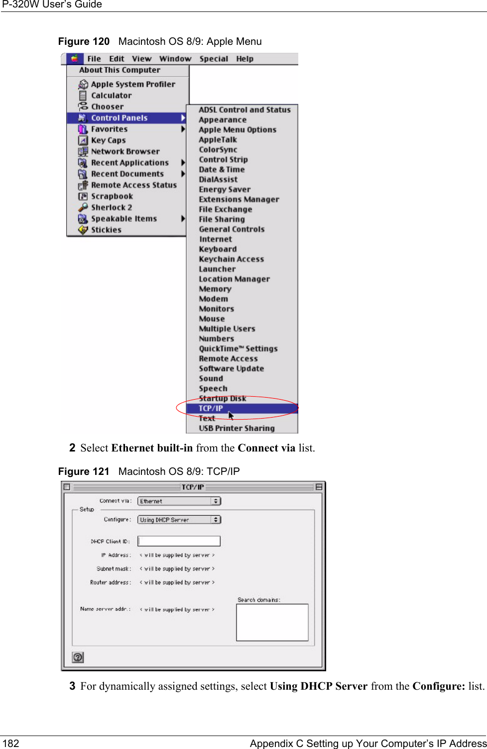
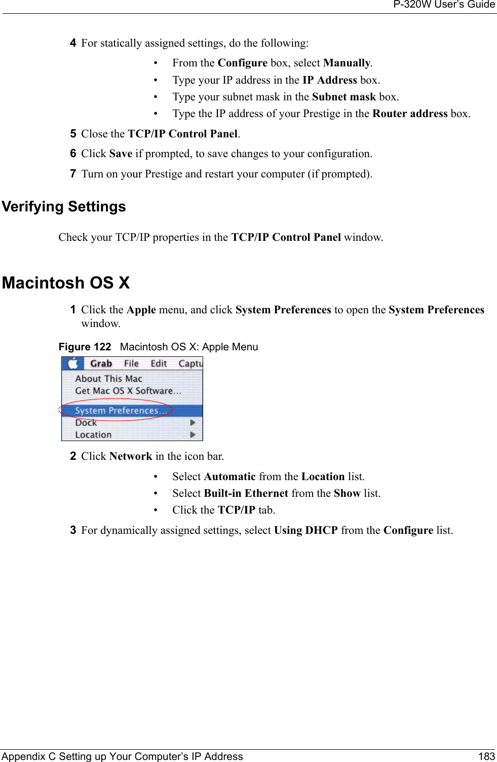
![P-320W User’s GuideAppendix C Setting up Your Computer’s IP Address 181Figure 119 Windows XP: Internet Protocol (TCP/IP) Properties8Click OK to close the Internet Protocol (TCP/IP) Properties window.9Click Close (OK in Windows 2000/NT) to close the Local Area Connection Properties window.10 Close the Network Connections window (Network and Dial-up Connections in Windows 2000/NT).11Turn on your Prestige and restart your computer (if prompted).Verifying Settings1Click Start, All Programs, Accessories and then Command Prompt.2In the Command Prompt window, type "ipconfig" and then press [ENTER]. You can also open Network Connections, right-click a network connection, click Status and then click the Support tab.Macintosh OS 8/9 1Click the Apple menu, Control Panel and double-click TCP/IP to open the TCP/IP Control Panel.](https://usermanual.wiki/ZyXEL-Communications/P320W.Users-Manual-5/User-Guide-598767-Page-1.png)
![P-320W User’s Guide188 Appendix C Setting up Your Computer’s IP AddressFigure 131 Red Hat 9.0: Restart Ethernet Card [root@localhost init.d]# network restartShutting down interface eth0: [OK]Shutting down loopback interface: [OK]Setting network parameters: [OK]Bringing up loopback interface: [OK]Bringing up interface eth0: [OK]Verifying SettingsEnter ifconfig in a terminal screen to check your TCP/IP properties. Figure 132 Red Hat 9.0: Checking TCP/IP Properties [root@localhost]# ifconfig eth0 Link encap:Ethernet HWaddr 00:50:BA:72:5B:44 inet addr:172.23.19.129 Bcast:172.23.19.255 Mask:255.255.255.0 UP BROADCAST RUNNING MULTICAST MTU:1500 Metric:1 RX packets:717 errors:0 dropped:0 overruns:0 frame:0 TX packets:13 errors:0 dropped:0 overruns:0 carrier:0 collisions:0 txqueuelen:100 RX bytes:730412 (713.2 Kb) TX bytes:1570 (1.5 Kb) Interrupt:10 Base address:0x1000 [root@localhost]#](https://usermanual.wiki/ZyXEL-Communications/P320W.Users-Manual-5/User-Guide-598767-Page-8.png)