ZyXEL Communications P320W 802.11g Wireless Firewall Router User Manual ZyBook
ZyXEL Communications Corporation 802.11g Wireless Firewall Router ZyBook
Contents
- 1. Users Manual 1
- 2. Users Manual 2
- 3. Users Manual 3
- 4. Users Manual 4
- 5. Users Manual 5
Users Manual 4
P-320W User’s Guide
Chapter 14 Logs 141
CHAPTER 14
Logs
This chapter contains information about configuring general log settings and viewing the
Prestige’s logs. Refer to the appendices for example log message explanations.
14.1 View Log
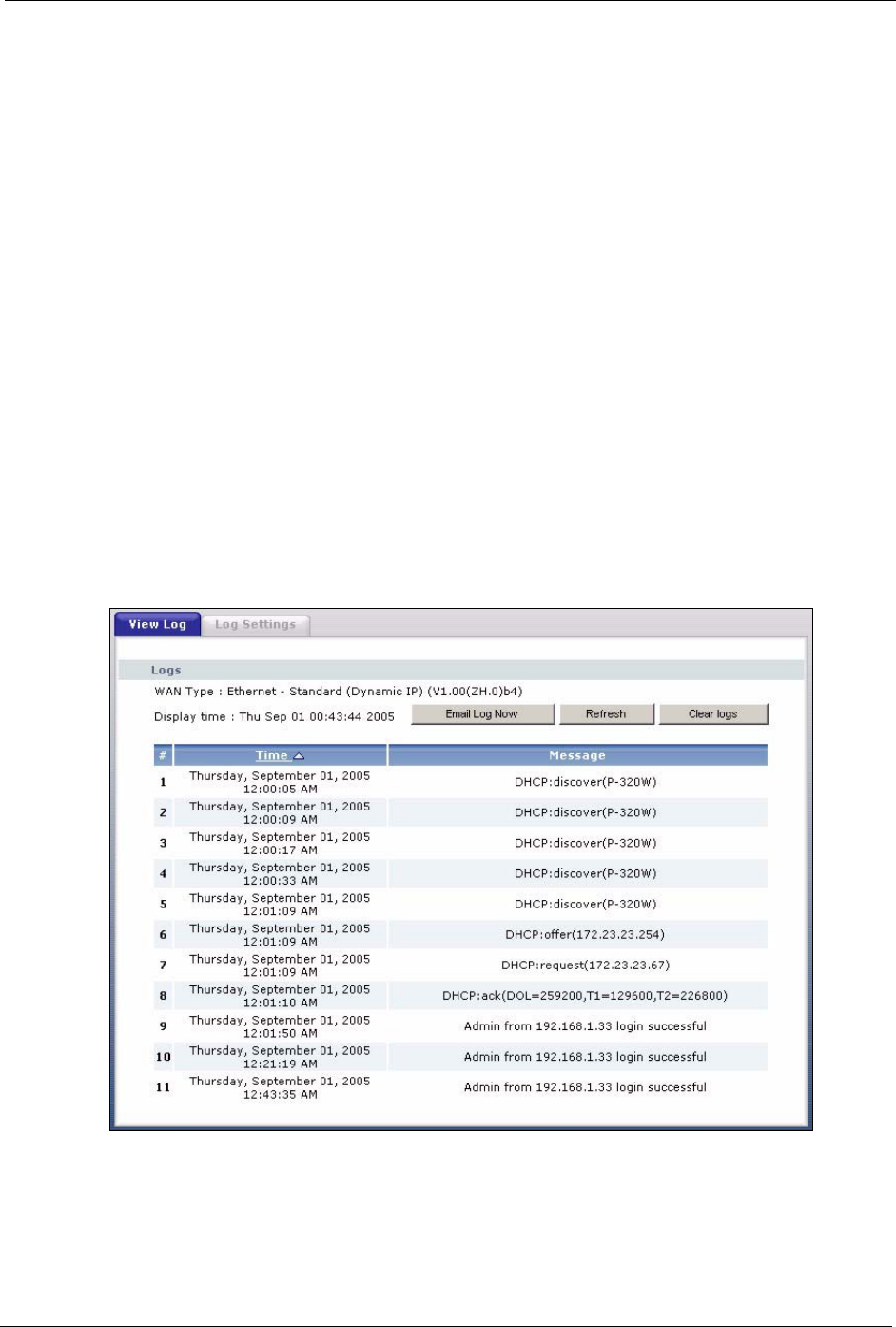
The web configurator allows you to look at all of the Prestige’s logs in one location.
Click the Logs link under Maintenance to open the View Log screen.
Log entries in red indicate system error logs. The log wraps around and deletes the old entries
after it fills. Click a column heading to sort the entries. A triangle indicates ascending or
descending sort order.
Figure 89 View Log

P-320W User’s Guide
142 Chapter 14 Logs
The following table describes the labels in this screen.
Table 59 View Log
LABEL DESCRIPTION
WAN Type This shows the encapsulation method (and service type) the Prestige is using and
the firmware version.
Display Time This displays the time this screen was refreshed.
Email Log Now Click Email Log Now to send the log screen to the e-mail address specified in the
Log Settings page (make sure that you have first filled in the E-mail Log Settings
fields in Log Settings).
Refresh Click Refresh to renew the log screen.
Clear Logs Click Clear Logs to delete all the logs.
Time This field displays the time the log was recorded. See the chapter on time setting to
configure the Prestige’s time and date.
Message This field states the reason for the log.
14.2 Log Settings
You can configure the Prestige’s general log settings in one location.
Click the Logs link under Maintenance in the navigation panel and the Log Settings tab to
open the Log Settings screen.
Use the Log Settings screen to configure to where the Prestige is to send logs; the schedule for
when the Prestige is to send the logs and which logs and/or immediate alerts the Prestige to
send.
An alert is a type of log that warrants more serious attention. They include system errors,
attacks (access control) and attempted access to blocked web sites or web sites with restricted
web features such as cookies, active X and so on. Some categories such as System Errors
consist of both logs and alerts. You may differentiate them by their color in the View Log
screen. Alerts display in red and logs display in black.
Alerts are e-mailed as soon as they happen. Logs may be e-mailed as soon as the log is full.
Selecting many alert and/or log categories (especially Access Control) may result in many e-
mails being sent
P-320W User’s Guide
Chapter 14 Logs 143
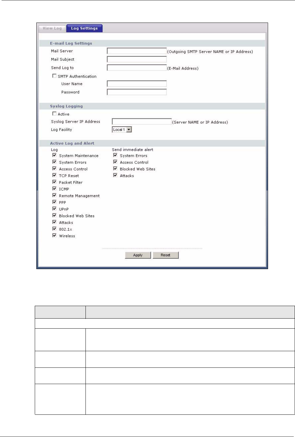
Figure 90 Log Settings
The following table describes the labels in this screen.
Table 60 Log Settings
LABEL DESCRIPTION
E-mail Log Settings
Mail Server Enter the server name or the IP address of the mail server for the e-mail addresses
specified below. If this field is left blank, logs and alert messages will not be sent
via E-mail.
Mail Subject Type a title that you want to be in the subject line of the log e-mail message that the
Prestige sends. Not all Prestige models have this field.
Send Log To The Prestige sends logs to the e-mail address specified in this field. If this field is
left blank, the Prestige does not send logs via e-mail.
SMTP
Authentication
SMTP (Simple Mail Transfer Protocol) is the message-exchange standard for the
Internet. SMTP enables you to move messages from one e-mail server to another.
Select the check box to activate SMTP authentication. If mail server authentication
is needed but this feature is disabled, you will not receive the e-mail logs.

P-320W User’s Guide
144 Chapter 14 Logs
User Name Enter the user name (up to 31 characters) (usually the user name of a mail
account).
Password Enter the password associated with the user name above.
Syslog Logging The Prestige sends a log to an external syslog server.
Active Click Active to enable syslog logging.
Syslog Server IP
Address
Enter the server name or IP address of the syslog server that will log the selected
categories of logs.
Log Facility Select a location from the drop down list box. The log facility allows you to log the
messages to different files in the syslog server. Refer to the syslog server manual
for more information.
Active Log and
Alert
Log Select the categories of logs that you want to record.
Send Immediate
Alert
Select log categories for which you want the Prestige to send E-mail alerts
immediately.
Apply Click Apply to save your changes.
Reset Click Reset to begin configuring this screen afresh.
Table 60 Log Settings (continued)
LABEL DESCRIPTION
P-320W User’s Guide
Chapter 15 Tools 145
CHAPTER 15
Tools
This chapter shows you how to upload a new firmware, upload or save backup configuration
files and restart the Prestige.
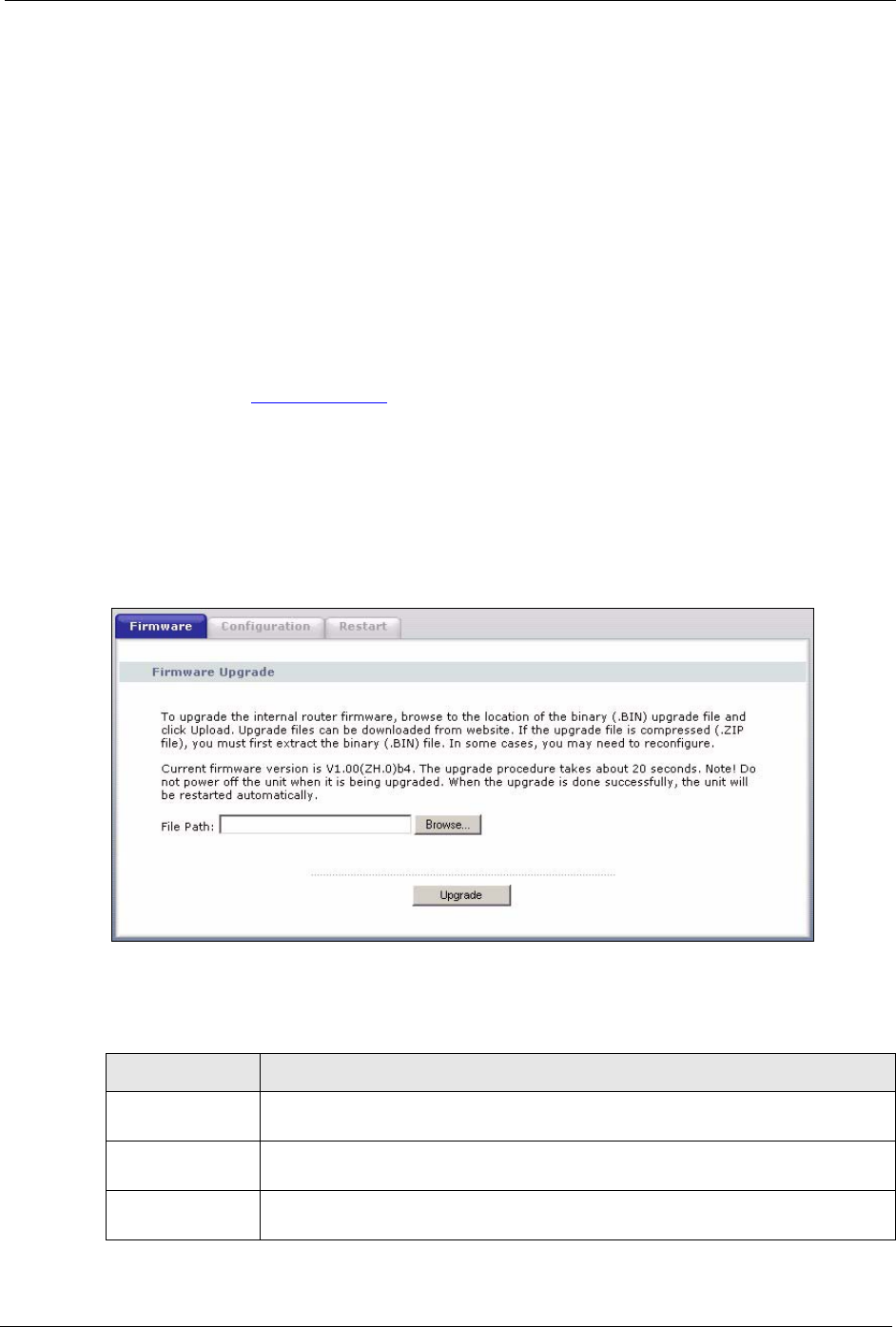
15.1 Firmware Upload Screen
Find firmware at www.zyxel.com in a file that (usually) uses the system model name with a
.bin extension, for example, "Prestige.bin". The upload process uses HTTP (Hypertext
Transfer Protocol) and may take up to two minutes. After a successful upload, the system will
reboot.
Click the Tools link under Maintenance in the navigation panel. Follow the instructions in
this screen to upload firmware to your Prestige.
Figure 91 Maintenance Firmware Upload
The following table describes the labels in this screen.
Table 61 Maintenance Firmware Upload
LABEL DESCRIPTION
File Path Type in the location of the file you want to upload in this field or click Browse ... to
find it.
Browse... Click Browse... to find the .bin file you want to upload. Remember that you must
decompress compressed (.zip) files before you can upload them.
Upgrade Click Upgrade to begin the upload process. This process may take up to two
minutes.
P-320W User’s Guide
146 Chapter 15 Tools
Note: Do not turn off the Prestige while firmware upload is in progress!
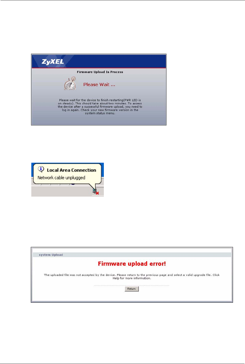
After you see the Firmware Upload In Process screen, wait two minutes before logging into
the Prestige again.
Figure 92 Upload Warning
The Prestige automatically restarts in this time causing a temporary network disconnect. In
some operating systems, you may see the following icon on your desktop.
Figure 93 Network Temporarily Disconnected
After two minutes, log in again and check your new firmware version in the Status screen.
If the upload was not successful, the following screen will appear. Click Return to go back to
the Firmware screen.
Figure 94 Upload Error Message
15.2 Configuration Screen
See the Firmware and Configuration File Maintenance chapter for transferring configuration
files using FTP/TFTP commands.
P-320W User’s Guide
Chapter 15 Tools 147
Click the Tools link under Maintenance, and the Configuration tab. Information related to
factory defaults, backup configuration, and restoring configuration appears as shown next.
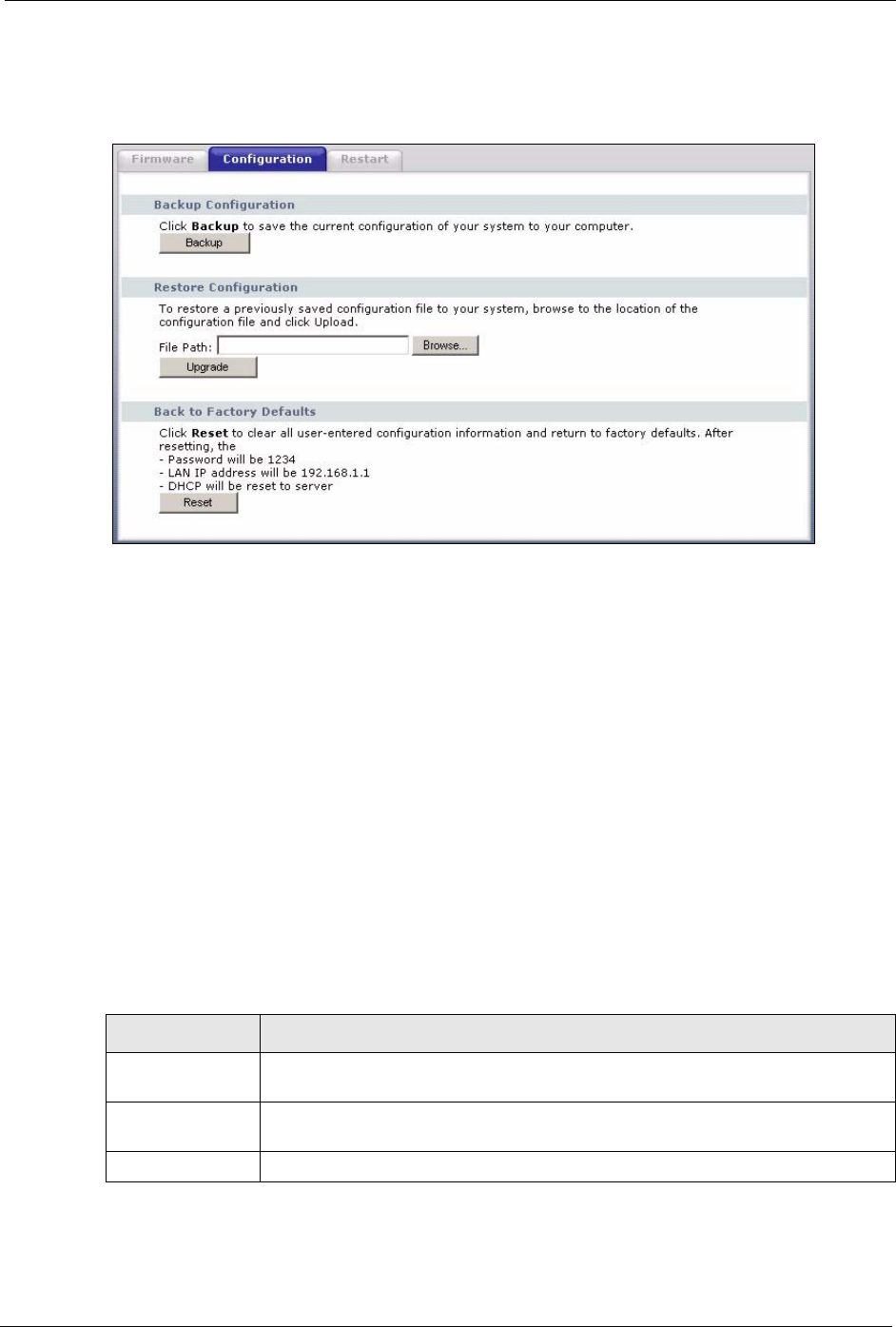
Figure 95 Configuration
15.2.1 Backup Configuration
Backup configuration allows you to back up (save) the Prestige’s current configuration to a
file on your computer. Once your Prestige is configured and functioning properly, it is highly
recommended that you back up your configuration file before making configuration changes.
The backup configuration file will be useful in case you need to return to your previous
settings.
Click Backup to save the Prestige’s current configuration to your computer
15.2.2 Restore Configuration
Restore configuration allows you to upload a new or previously saved configuration file from
your computer to your Prestige.
Table 62 Maintenance: Restore Configuration
LABEL DESCRIPTION
File Path Type in the location of the file you want to upload in this field or click Browse ... to
find it.
Browse... Click Browse... to find the file you want to upload. Remember that you must
decompress compressed (.ZIP) files before you can upload them.
Upgrade Click Upgrade to begin the upload process.
Note: Do not turn off the Prestige while configuration file upload is in progress
P-320W User’s Guide
148 Chapter 15 Tools
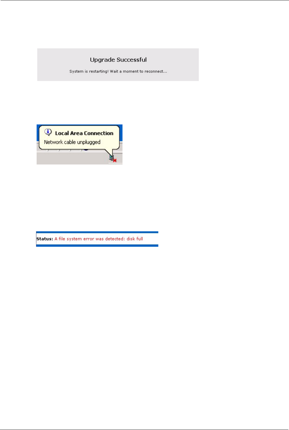
After you see a “Upgrade Successful” screen, you must then wait one minute before logging
into the Prestige again.
Figure 96 Configuration Restore Successful
The Prestige automatically restarts in this time causing a temporary network disconnect. In
some operating systems, you may see the following icon on your desktop.
Figure 97 Temporarily Disconnected
If you uploaded the default configuration file you may need to change the IP address of your
computer to be in the same subnet as that of the default Prestige IP address (192.168.1.1). See
the appendix for details on how to set up your computer’s IP address.
If the upload was not successful, the following screen will appear.
Figure 98 Configuration Restore Error
15.2.3 Back to Factory Defaults
Pressing the Restart button in this section clears all user-entered configuration information
and returns the Prestige to its factory defaults.
You can also press the RESET button on the rear panel to reset the factory defaults of your
Prestige. Refer to Chapter 2 on page 35 for more information on the RESET button.
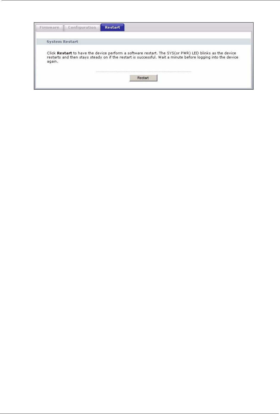
15.3 Restart Screen
System restart allows you to reboot the Prestige without turning the power off.
Click the Tools link under Maintenance, and the Restart tab. Click Restart to have the
Prestige reboot. This does not affect the Prestige's configuration.
P-320W User’s Guide
Chapter 15 Tools 149
Figure 99 System Restart

P-320W User’s Guide
150 Chapter 15 Tools

P-320W User’s Guide
Chapter 16 Troubleshooting 151
CHAPTER 16
Troubleshooting
This chapter covers potential problems and the corresponding remedies.
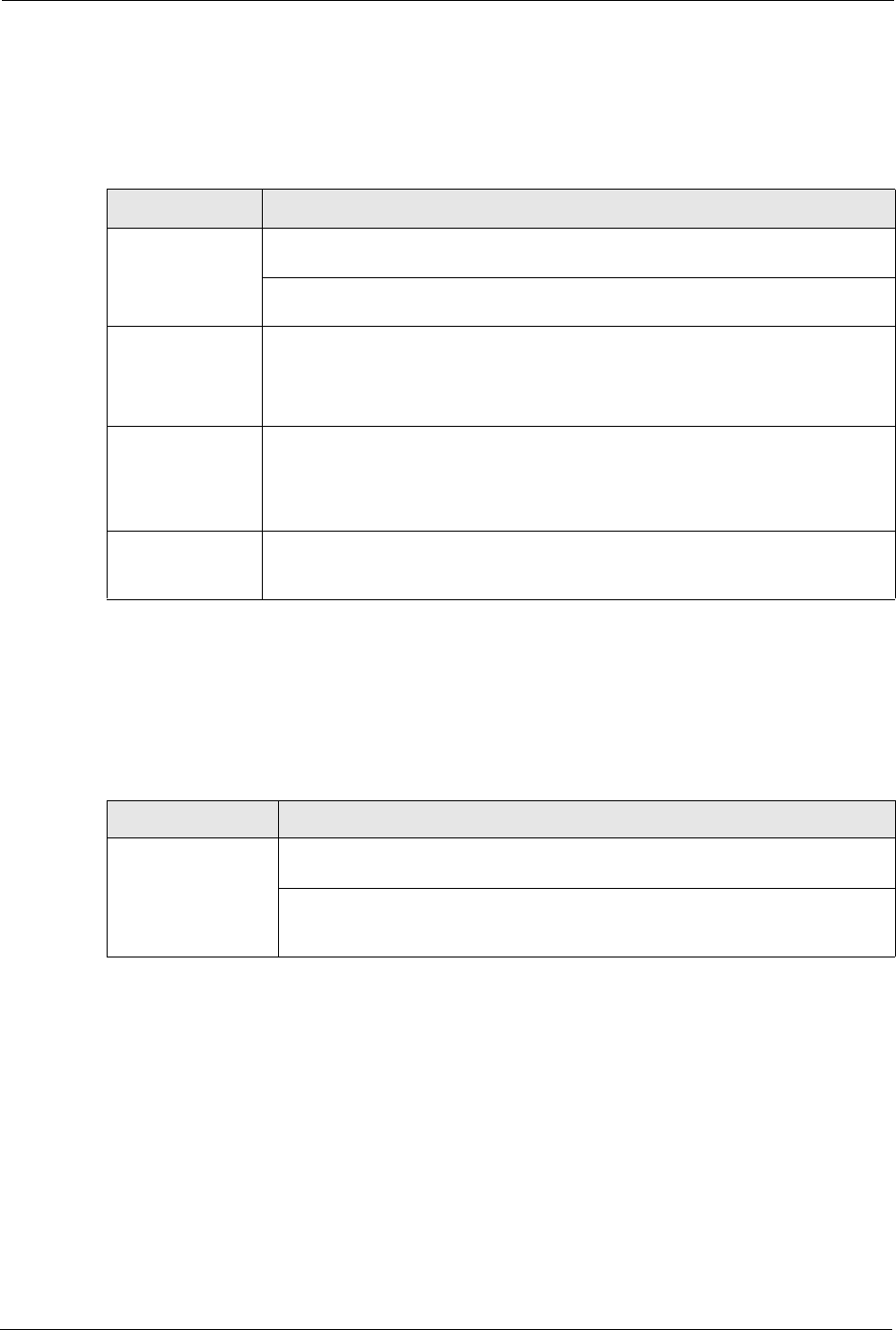
16.1 Problems Starting Up the Prestige
Table 63 Troubleshooting Starting Up Your Prestige
PROBLEM CORRECTIVE ACTION
None of the
LEDs turn on
when I turn on
the Prestige.
Make sure that the Prestige’s power adaptor is connected to the Prestige and plugged
in to an appropriate power source. Make sure that the Prestige and the power source
are both turned on.
Turn the Prestige off and on.
If the error persists, you may have a hardware problem. In this case, you should
contact your vendor.
16.2 Problems with the LAN
Table 64 Troubleshooting the LAN
PROBLEM CORRECTIVE ACTION
The LAN LEDs
do not turn on.
Check your Ethernet cable connections (refer to the Quick Start Guide for details).
Check for faulty Ethernet cables.
Make sure your computer’s Ethernet Card is working properly.
I cannot access
the Prestige from
the LAN.
If Any IP is disabled, make sure that the IP address and the subnet mask of the
Prestige and your computer(s) are on the same subnet.
P-320W User’s Guide
152 Chapter 16 Troubleshooting
16.3 Problems with the WAN
Table 65 Troubleshooting the WAN
PROBLEM CORRECTIVE ACTION
The WAN LED is
off.
Check the connections between the Prestige WAN port and the cable/DSL modem
or ethernet jack.
Check whether your cable/DSL device requires a crossover or straight-through
cable.
I cannot get a
WAN IP address
from the ISP.
Click WAN to verify your settings.
The username and password apply to PPPoE and PPPoA encapsulation only.
Make sure that you have entered the correct Service Type, User Name and
Password (be sure to use the correct casing). Refer to the WAN Setup chapter.
I cannot access
the Internet.
Make sure the Prestige is turned on and connected to the network.
Verify your WAN settings. Refer to the chapter on WAN setup.
Make sure you entered the correct user name and password.
If you use PPPoE pass through, make sure that bridge mode is turned on.
The Internet
connection
disconnects.
If you use PPPoE encapsulation, check the idle time-out setting. Refer to the
Chapter 5 on page 81.
16.4 Problems with the Password
Table 66 Troubleshooting the Password
PROBLEM CORRECTIVE ACTION
Cannot access the
Prestige.
The password field is case sensitive. Make sure that you enter the correct
password using the proper casing.
Use the RESET button to restore the factory default configuration file. This will
restore all of the factory defaults including the password; see Section 2.3 on
page 37 for details.

P-320W User’s Guide
Chapter 16 Troubleshooting 153
16.5 Problems with Remote Management
Table 67 Troubleshooting Telnet
PROBLEM CORRECTIVE ACTION
Cannot access the
Prestige from the
LAN or WAN.
Refer to Section 11.1.1 on page 119 for scenarios when remote management
may not be possible.
When NAT is enabled:
• Use the Prestige's WAN IP address when configuring from the WAN.
• Use the Prestige's LAN IP address when configuring from the LAN.
16.6 Problems Accessing the Prestige
Table 68 Troubleshooting Accessing the Prestige
PROBLEM CORRECTIVE ACTION
I cannot
access the
Prestige.
The username is “admin”. The default password is “1234”. The Password and
Username fields are case-sensitive. Make sure that you enter the correct password
and username using the proper casing.
If you have changed the password and have now forgotten it, you will need to upload
the default configuration file. This restores all of the factory defaults including the
password.
I cannot
access the
web
configurator.
Use the Prestige’s WAN IP address when configuring from the WAN. Refer to the
instructions on checking your WAN connection.
Use the Prestige’s LAN IP address when configuring from the LAN. Refer to for
instructions on checking your LAN connection.
Check that you have enabled web service access. If you have configured a secured
client IP address, your computer’s IP address must match it. Refer to the chapter on
remote management for details.
Your computer’s and the Prestige’s IP addresses must be on the same subnet for LAN
access.
If you changed the Prestige’s LAN IP address, then enter the new one as the URL.
See the following section to check that pop-up windows, JavaScripts and Java
permissions are allowed.
You may also need to clear your Internet browser’s cache.
In Internet Explorer, click Tools and then Internet Options to open the Internet
Options screen.
In the General tab, click Delete Files. In the pop-up window, select the Delete all
offline content check box and click OK. Click OK in the Internet Options screen to
close it.
If you disconnect your computer from one device and connect it to another device that
has the same IP address, your computer’s ARP (Address Resolution Protocol) table
may contain an entry that maps the management IP address to the previous device’s
MAC address).
In Windows, use arp -d at the command prompt to delete all entries in your computer’s
ARP table.
P-320W User’s Guide
154 Chapter 16 Troubleshooting
16.6.1 Pop-up Windows, JavaScripts and Java Permissions
In order to use the web configurator you need to allow:
• Web browser pop-up windows from your device.
• JavaScripts (enabled by default).
• Java permissions (enabled by default).
Note: Internet Explorer 6 screens are used here. Screens for other Internet Explorer
versions may vary.
16.6.1.1 Internet Explorer Pop-up Blockers
You may have to disable pop-up blocking to log into your device.
Either disable pop-up blocking (enabled by default in Windows XP SP (Service Pack) 2) or
allow pop-up blocking and create an exception for your device’s IP address.
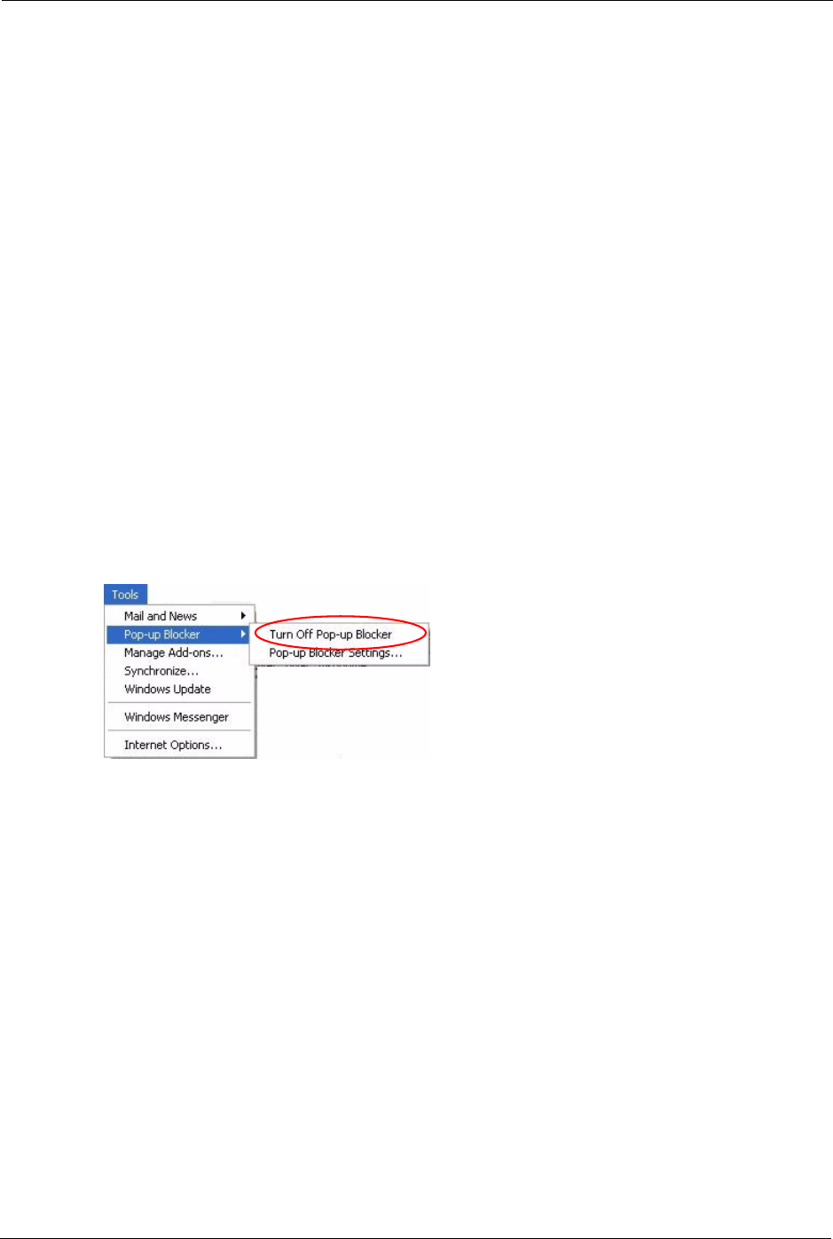
16.6.1.1.1 Disable pop-up Blockers
1In Internet Explorer, select Tools, Pop-up Blocker and then select Turn Off Pop-up
Blocker.
Figure 100 Pop-up Blocker
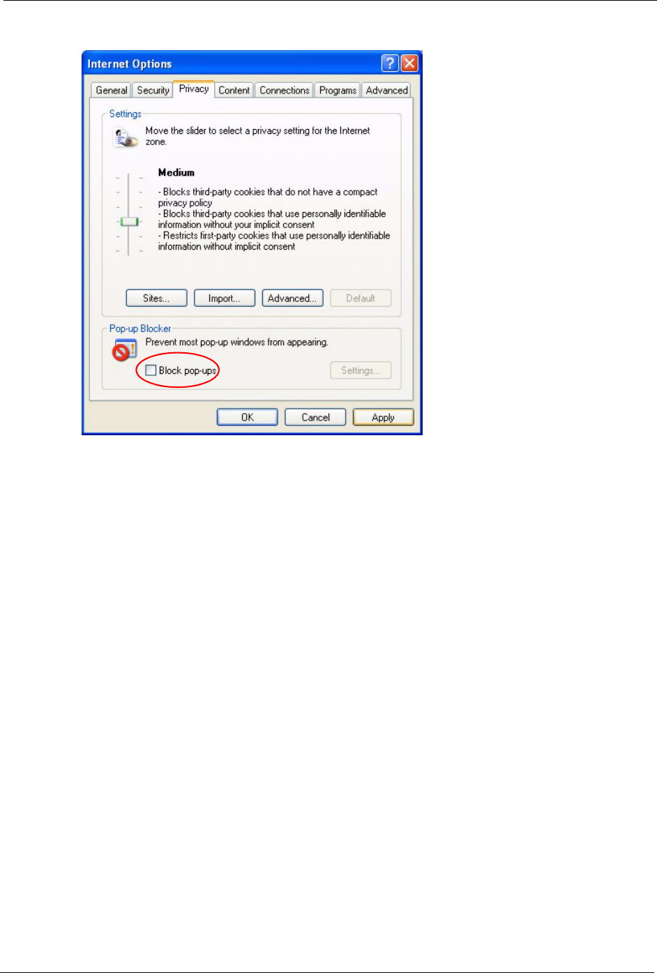
You can also check if pop-up blocking is disabled in the Pop-up Blocker section in the
Privacy tab.
1In Internet Explorer, select Tools, Internet Options, Privacy.
2Clear the Block pop-ups check box in the Pop-up Blocker section of the screen. This
disables any web pop-up blockers you may have enabled.
P-320W User’s Guide
Chapter 16 Troubleshooting 155
Figure 101 Internet Options
3Click Apply to save this setting.
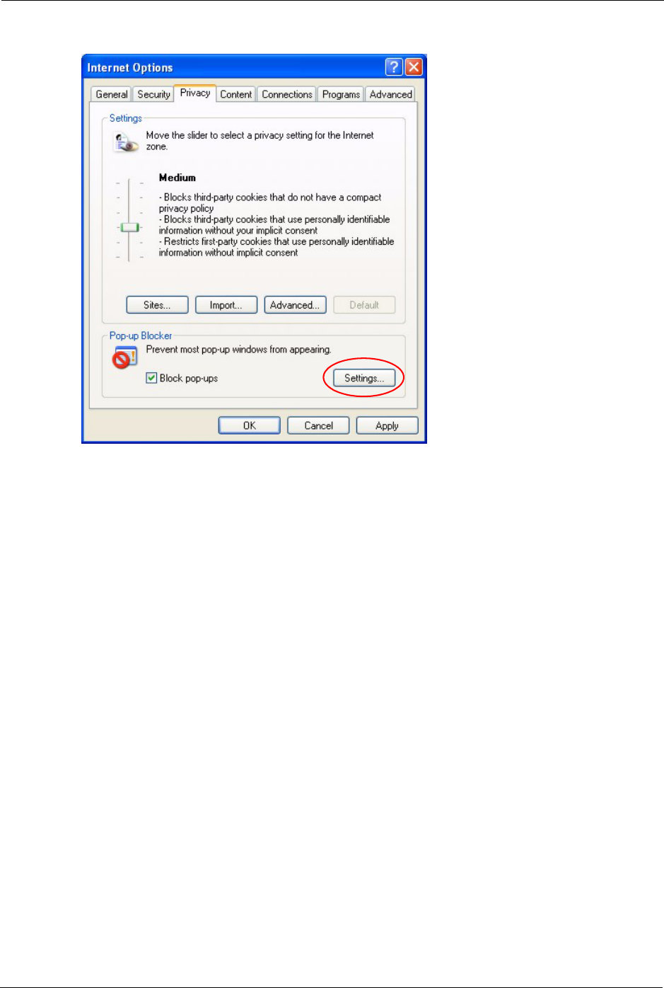
16.6.1.1.2 Enable pop-up Blockers with Exceptions
Alternatively, if you only want to allow pop-up windows from your device, see the following
steps.
1In Internet Explorer, select Tools, Internet Options and then the Privacy tab.
2Select Settings…to open the Pop-up Blocker Settings screen.
P-320W User’s Guide
156 Chapter 16 Troubleshooting
Figure 102 Internet Options
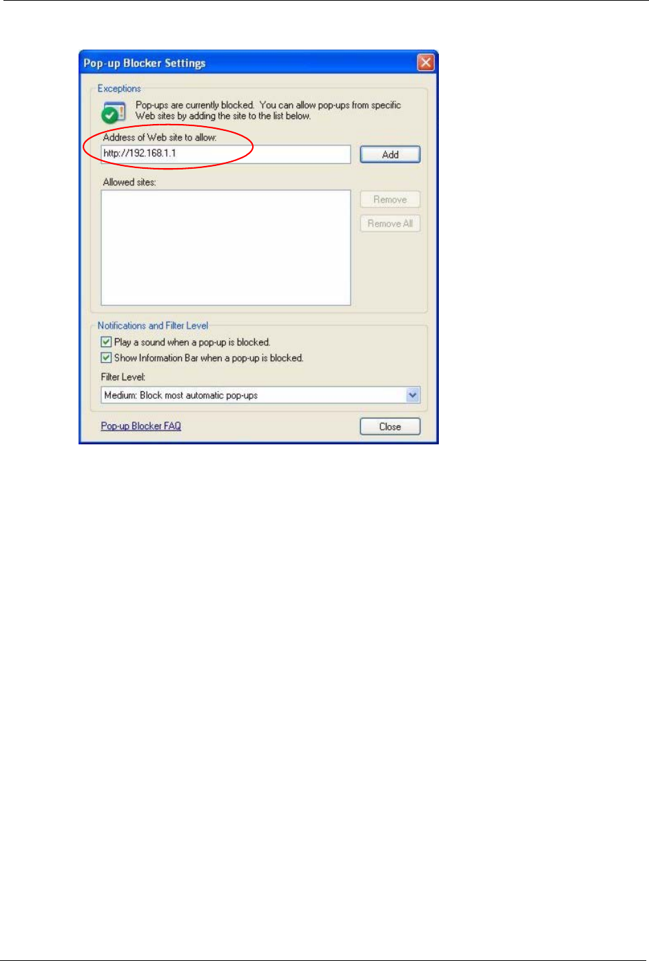
3Type the IP address of your device (the web page that you do not want to have blocked)
with the prefix “http://”. For example, http://192.168.1.1.
4Click Add to move the IP address to the list of Allowed sites.
Note: If you change the IP address of your device, make sure that the new address
matches the address you type in the Pop-up Blocker Settings screen.
P-320W User’s Guide
Chapter 16 Troubleshooting 157
Figure 103 Pop-up Blocker Settings
5Click Close to return to the Privacy screen.
6Click Apply to save this setting.
16.6.1.2 JavaScripts
If pages of the web configurator do not display properly in Internet Explorer, check that
JavaScripts are allowed.
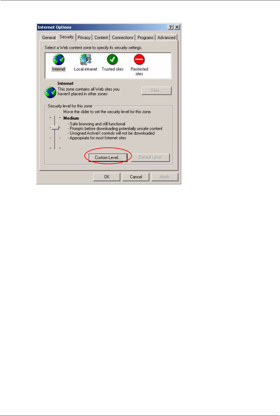
1In Internet Explorer, click Tools, Internet Options and then the Security tab.
P-320W User’s Guide
158 Chapter 16 Troubleshooting
Figure 104 Internet Options
2Click the Custom Level... button.
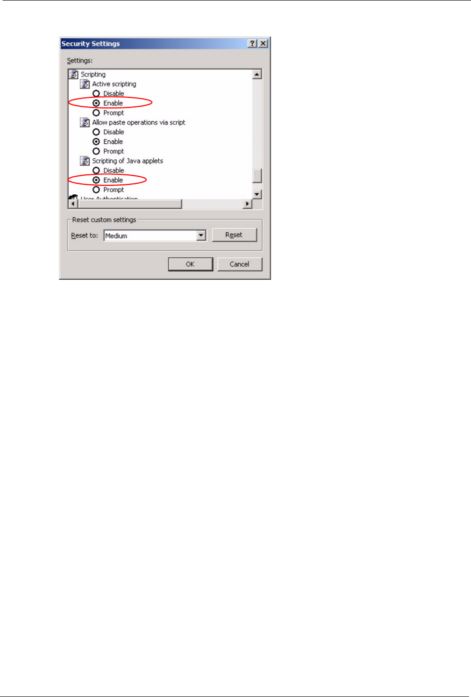
3Scroll down to Scripting.
4Under Active scripting make sure that Enable is selected (the default).
5Under Scripting of Java applets make sure that Enable is selected (the default).
6Click OK to close the window.
P-320W User’s Guide
Chapter 16 Troubleshooting 159
Figure 105 Security Settings - Java Scripting
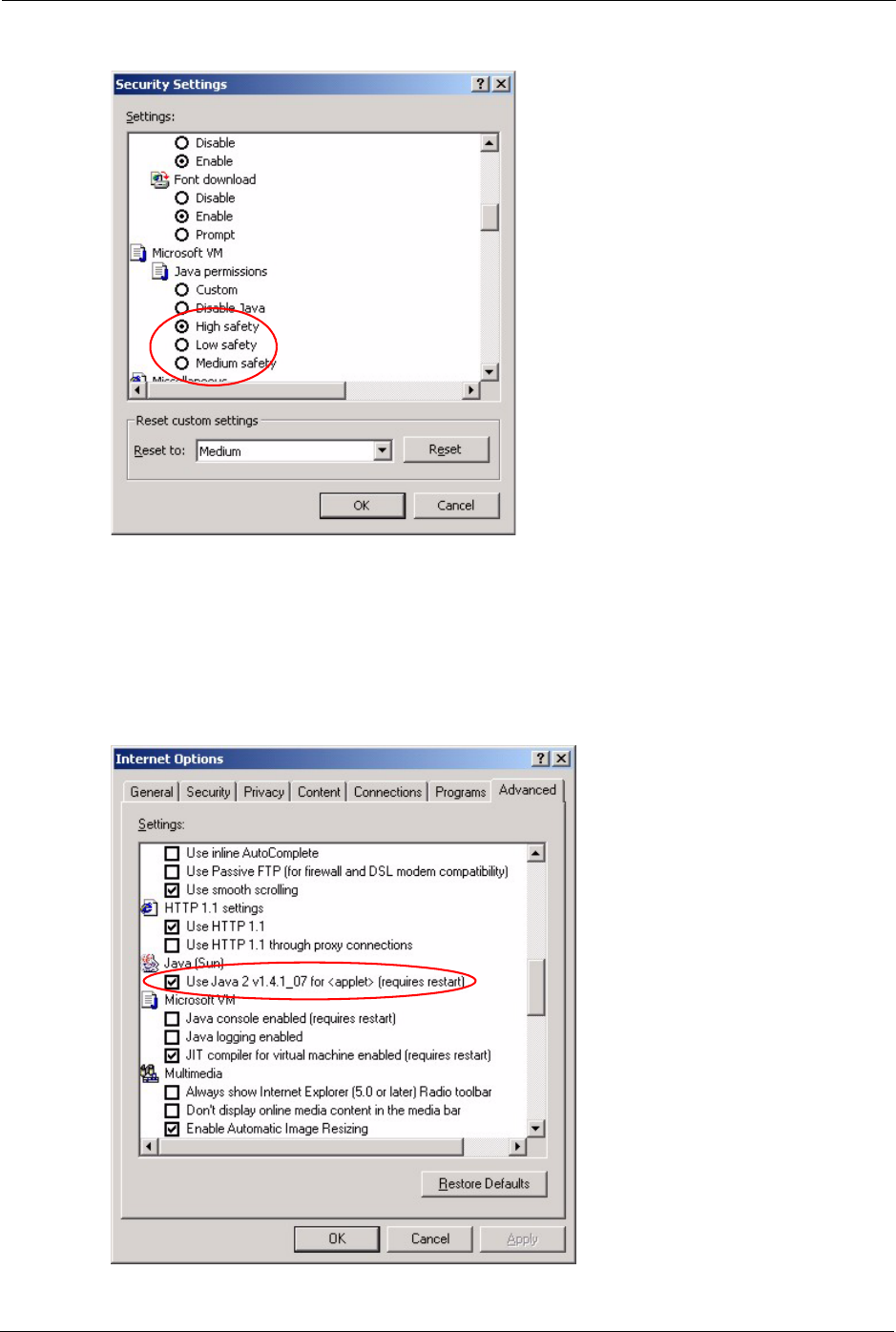
16.6.1.3 Java Permissions
1From Internet Explorer, click Tools, Internet Options and then the Security tab.
2Click the Custom Level... button.
3Scroll down to Microsoft VM.
4Under Java permissions make sure that a safety level is selected.
5Click OK to close the window.
P-320W User’s Guide
160 Chapter 16 Troubleshooting
Figure 106 Security Settings - Java
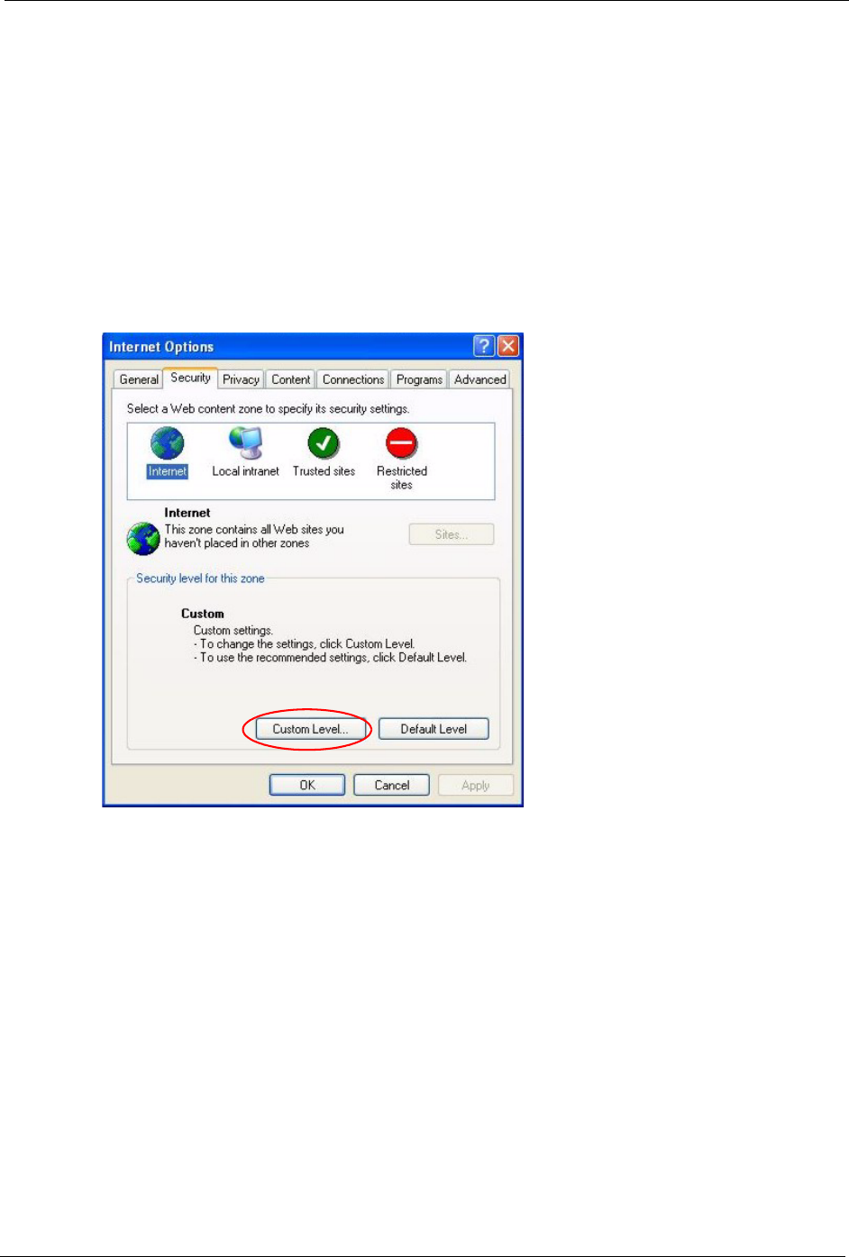
16.6.1.3.1 JAVA (Sun)
1From Internet Explorer, click Tools, Internet Options and then the Advanced tab.
2Make sure that Use Java 2 for <applet> under Java (Sun) is selected.
3Click OK to close the window.
Figure 107 Java (Sun)
P-320W User’s Guide
Chapter 16 Troubleshooting 161
16.6.2 ActiveX Controls in Internet Explorer
If ActiveX is disabled, you will not be able to download ActiveX controls or to use Trend
Micro Security Serivces. Make sure that ActiveX controls are allowed in Internet Explorer.
Screen shots for Internet Explorer 6 are shown. Steps may vary depending on your version of
Internet Explorer.
1In Internet Explorer, click Tools, Internet Options and then the Security tab.
2In the Internet Options window, click Custom Level.
Figure 108 Internet Options Security
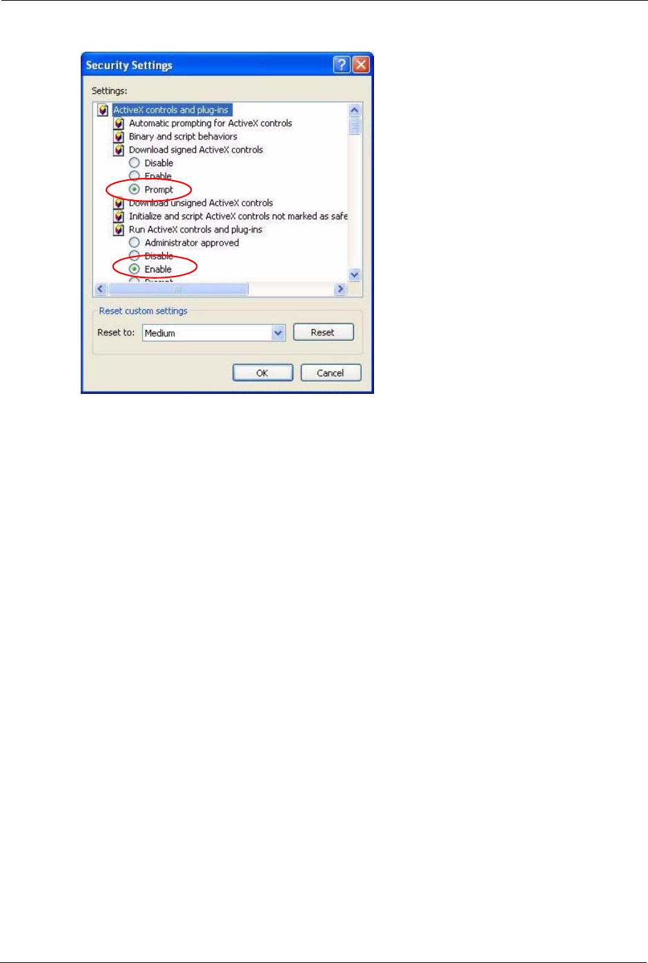
3Scroll down to ActiveX controls and plug-ins.
4Under Download signed ActiveX controls select the Prompt radio button.
5Under Run ActiveX controls and plug-ins make sure the Enable radio button is
selected.
6Then click the OK button.
P-320W User’s Guide
162 Chapter 16 Troubleshooting
Figure 109 Security Setting ActiveX Controls

P-320W User’s Guide
Appendix A Product Specifications 163
APPENDIX A
Product Specifications
See also the Introduction chapter for a general overview of the key features.
Specification Tables
Table 69 Device
Default IP Address 192.168.1.1
Default Subnet Mask 255.255.255.0 (24 bits)
Default Password 1234
DHCP Pool 192.168.1.32 to 192.168.1.64
Dimensions (181 W) x (128 D) x (36 H) mm
Weight 424g
Power Specification 12VAC
Built-in Switch Four auto-negotiating, auto MDI/MDI-X 10/100/1000 Mbps RJ-45 Ethernet
ports
Operation Temperature 0º C ~ 65º C
Storage Temperature -20º ~ 60º C
Operation Humidity 15% ~ 90% RH
Storage Humidity 10% ~ 90% RH
Table 70 Firmware
Standards IEEE 802.3 Ethernet
IEEE 802.3u Fast Ethernet
IEEE 802.3ab Gigabit Ethernet
TCP, UDP, ICMP, ARP, RIP - 1/RIP - 2
IP Routing (RFC 791)
PPP over Ethernet (RFC 2516)
MAC encapsulated routing (ENET encapsulation)
Other Protocol Support PPP (Point-to-Point Protocol) link layer protocol.
DHCP Server (RFC 2131, 2132)
RIP I/RIP II
ICMP
SNMP v1 and v2c with MIB II support (RFC 1213)
UPnP
Management Embedded Web Configurator
Remote Management via Web
SNMP manageable
Configuration backup and restoration.
Built-in Diagnostic Tools for FLASH memory, RAM and LAN port
Syslog

P-320W User’s Guide
164 Appendix A Product Specifications
Wireless IEEE 802.11g Compliance
Frequency Range: 2.4 GHz
Advanced Orthogonal Frequency Division Multiplexing (OFDM)
Data Rates: 54Mbps and Auto Fallback
Wired Equivalent Privacy (WEP) Data Encryption 64/128/256 bit.
WLAN bridge to LAN
Up to 32 MAC Address filters
WPA, WPA-PSK
OTIST (One Touch Intelligent Security Technology)
IEEE 802.1x
External Radius server using EAP-MD5, TLS, TTLS
Firewall Stateful Packet Inspection.
Prevent Denial of Service attacks such as Fraggle, SYN Flood, Land attack,
Smurf etc.
Real time E-mail alerts
Reports and logs
NAT/SUA Port Forwarding
4096 NAT sessions
Multimedia application
PPTP under NAT/SUA
IPSec passthrough
SIP ALG passthrough
Cone NAT (Port-restricted NAT)
Static Routes 8 IP
Other Features Traffic Redirect
Dynamic DNS
SMTP Authentication
Table 70 Firmware (continued)

P-320W User’s Guide
Appendix B IP Subnetting 165
APPENDIX B
IP Subnetting
IP Addressing
Routers “route” based on the network number. The router that delivers the data packet to the
correct destination host uses the host ID.
IP Classes
An IP address is made up of four octets (eight bits), written in dotted decimal notation, for
example, 192.168.1.1. IP addresses are categorized into different classes. The class of an
address depends on the value of its first octet.
• Class “A” addresses have a 0 in the left most bit. In a class “A” address the first octet is
the network number and the remaining three octets make up the host ID.
• Class “B” addresses have a 1 in the left most bit and a 0 in the next left most bit. In a class
“B” address the first two octets make up the network number and the two remaining
octets make up the host ID.
• Class “C” addresses begin (starting from the left) with 1 1 0. In a class “C” address the
first three octets make up the network number and the last octet is the host ID.
• Class “D” addresses begin with 1 1 1 0. Class “D” addresses are used for multicasting.
(There is also a class “E” address. It is reserved for future use.)
Table 71 Classes of IP Addresses
IP ADDRESS: OCTET 1 OCTET 2 OCTET 3 OCTET 4
Class A 0Network number Host ID Host ID Host ID
Class B 10 Network number Network number Host ID Host ID
Class C 110 Network number Network number Network number Host ID
Note: Host IDs of all zeros or all ones are not allowed.
Therefore:
A class “C” network (8 host bits) can have 28 –2 or 254 hosts.
A class “B” address (16 host bits) can have 216 –2 or 65534 hosts.
A class “A” address (24 host bits) can have 224 –2 hosts (approximately 16 million hosts).

P-320W User’s Guide
166 Appendix B IP Subnetting
Since the first octet of a class “A” IP address must contain a “0”, the first octet of a class “A”
address can have a value of 0 to 127.
Similarly the first octet of a class “B” must begin with “10”, therefore the first octet of a class
“B” address has a valid range of 128 to 191. The first octet of a class “C” address begins with
“110”, and therefore has a range of 192 to 223.
Table 72 Allowed IP Address Range By Class
CLASS ALLOWED RANGE OF FIRST OCTET
(BINARY)
ALLOWED RANGE OF FIRST OCTET
(DECIMAL)
Class A 00000000 to 01111111 0 to 127
Class B 10000000 to 10111111 128 to 191
Class C 11000000 to 11011111 192 to 223
Class D 11100000 to 11101111 224 to 239
Subnet Masks
A subnet mask is used to determine which bits are part of the network number, and which bits
are part of the host ID (using a logical AND operation). A subnet mask has 32 is a “1” then
the corresponding bit in the IP address is part of the network number. If a bit in the subnet
mask is “0” then the corresponding bit in the IP address is part of the host ID.
Subnet masks are expressed in dotted decimal notation just as IP addresses are. The “natural”
masks for class A, B and C IP addresses are as follows.
Table 73 “Natural” Masks
CLASS NATURAL MASK
A255.0.0.0
B255.255.0.0
C255.255.255.0
Subnetting
With subnetting, the class arrangement of an IP address is ignored. For example, a class C
address no longer has to have 24 bits of network number and 8 bits of host ID. With
subnetting, some of the host ID bits are converted into network number bits. By convention,
subnet masks always consist of a continuous sequence of ones beginning from the left most bit
of the mask, followed by a continuous sequence of zeros, for a total number of 32 bits.
P-320W User’s Guide
Appendix B IP Subnetting 167
Since the mask is always a continuous number of ones beginning from the left, followed by a
continuous number of zeros for the remainder of the 32 bit mask, you can simply specify the
number of ones instead of writing the value of each octet. This is usually specified by writing
a “/” followed by the number of bits in the mask after the address.
For example, 192.1.1.0 /25 is equivalent to saying 192.1.1.0 with mask 255.255.255.128.
The following table shows all possible subnet masks for a class “C” address using both
notations.
Table 74 Alternative Subnet Mask Notation
SUBNET MASK IP ADDRESS SUBNET MASK “1” BITS LAST OCTET BIT VALUE
255.255.255.0 /24 0000 0000
255.255.255.128 /25 1000 0000
255.255.255.192 /26 1100 0000
255.255.255.224 /27 1110 0000
255.255.255.240 /28 1111 0000
255.255.255.248 /29 1111 1000
255.255.255.252 /30 1111 1100
The first mask shown is the class “C” natural mask. Normally if no mask is specified it is
understood that the natural mask is being used.
Example: Two Subnets
As an example, you have a class “C” address 192.168.1.0 with subnet mask of 255.255.255.0.
Table 75 Two Subnets Example
NETWORK NUMBER HOST ID
IP Address 192.168.1. 0
IP Address (Binary) 11000000.10101000.00000001. 00000000
Subnet Mask 255.255.255. 0
Subnet Mask (Binary) 11111111.11111111.11111111. 00000000
The first three octets of the address make up the network number (class “C”). You want to
have two separate networks.
Divide the network 192.168.1.0 into two separate subnets by converting one of the host ID bits
of the IP address to a network number bit. The “borrowed” host ID bit can be either “0” or “1”
thus giving two subnets; 192.168.1.0 with mask 255.255.255.128 and 192.168.1.128 with
mask 255.255.255.128.
P-320W User’s Guide
168 Appendix B IP Subnetting
Note: In the following charts, shaded/bolded last octet bit values indicate host ID bits
“borrowed” to form network ID bits. The number of “borrowed” host ID bits
determines the number of subnets you can have. The remaining number of
host ID bits (after “borrowing”) determines the number of hosts you can have
on each subnet.
Table 76 Subnet 1
NETWORK NUMBER LAST OCTET BIT
VALUE
IP Address 192.168.1. 0
IP Address (Binary) 11000000.10101000.00000001. 00000000
Subnet Mask 255.255.255. 128
Subnet Mask (Binary) 11111111.11111111.11111111. 10000000
Subnet Address: 192.168.1.0 Lowest Host ID: 192.168.1.1
Broadcast Address:
192.168.1.127
Highest Host ID: 192.168.1.126
Table 77 Subnet 2
NETWORK NUMBER LAST OCTET BIT VALUE
IP Address 192.168.1. 128
IP Address (Binary) 11000000.10101000.00000001. 10000000
Subnet Mask 255.255.255. 128
Subnet Mask (Binary) 11111111.11111111.11111111. 10000000
Subnet Address:
192.168.1.128
Lowest Host ID: 192.168.1.129
Broadcast Address:
192.168.1.255
Highest Host ID: 192.168.1.254
The remaining 7 bits determine the number of hosts each subnet can have. Host IDs of all
zeros represent the subnet itself and host IDs of all ones are the broadcast address for that
subnet, so the actual number of hosts available on each subnet in the example above is 27 – 2
or 126 hosts for each subnet.
192.168.1.0 with mask 255.255.255.128 is the subnet itself, and 192.168.1.127 with mask
255.255.255.128 is the directed broadcast address for the first subnet. Therefore, the lowest IP
address that can be assigned to an actual host for the first subnet is 192.168.1.1 and the highest
is 192.168.1.126. Similarly the host ID range for the second subnet is 192.168.1.129 to
192.168.1.254.
P-320W User’s Guide
Appendix B IP Subnetting 169
Example: Four Subnets
The above example illustrated using a 25-bit subnet mask to divide a class “C” address space
into two subnets. Similarly to divide a class “C” address into four subnets, you need to
“borrow” two host ID bits to give four possible combinations of 00, 01, 10 and 11. The subnet
mask is 26 bits (11111111.11111111.11111111.11000000) or 255.255.255.192. Each subnet
contains 6 host ID bits, giving 26-2 or 62 hosts for each subnet (all 0’s is the subnet itself, all
1’s is the broadcast address on the subnet).
Table 78 Subnet 1
NETWORK NUMBER LAST OCTET BIT
VALUE
IP Address 192.168.1. 0
IP Address (Binary) 11000000.10101000.00000001. 00000000
Subnet Mask (Binary) 11111111.11111111.11111111. 11000000
Subnet Address: 192.168.1.0 Lowest Host ID: 192.168.1.1
Broadcast Address:
192.168.1.63
Highest Host ID: 192.168.1.62
Table 79 Subnet 2
NETWORK NUMBER LAST OCTET BIT
VALUE
IP Address 192.168.1. 64
IP Address (Binary) 11000000.10101000.00000001. 01000000
Subnet Mask (Binary) 11111111.11111111.11111111. 11000000
Subnet Address: 192.168.1.64 Lowest Host ID: 192.168.1.65
Broadcast Address: 192.168.1.127 Highest Host ID: 192.168.1.126
Table 80 Subnet 3
NETWORK NUMBER LAST OCTET BIT
VALUE
IP Address 192.168.1. 128
IP Address (Binary) 11000000.10101000.00000001. 10000000
Subnet Mask (Binary) 11111111.11111111.11111111. 11000000
Subnet Address:
192.168.1.128
Lowest Host ID: 192.168.1.129
Broadcast Address:
192.168.1.191
Highest Host ID: 192.168.1.190
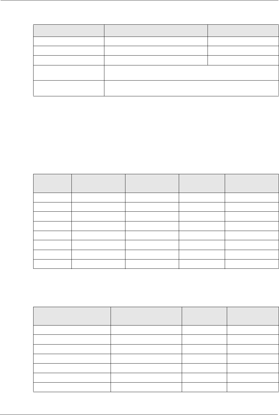
Table 81 Subnet 4
NETWORK NUMBER LAST OCTET BIT VALUE
IP Address 192.168.1. 192
IP Address (Binary) 11000000.10101000.00000001. 11000000
Subnet Mask (Binary) 11111111.11111111.11111111. 11000000
Subnet Address:
192.168.1.192
Lowest Host ID: 192.168.1.193
Broadcast Address:
192.168.1.255
Highest Host ID: 192.168.1.254
P-320W User’s Guide
170 Appendix B IP Subnetting
Example Eight Subnets
Similarly use a 27-bit mask to create 8 subnets (001, 010, 011, 100, 101, 110).
The following table shows class C IP address last octet values for each subnet.
Table 82 Eight Subnets
SUBNET SUBNET ADDRESS FIRST ADDRESS LAST ADDRESS BROADCAST
ADDRESS
1 0 1 30 31
232 33 62 63
364 65 94 95
496 97 126 127
5128 129 158 159
6160 161 190 191
7192 193 222 223
8224 225 254 255
The following table is a summary for class “C” subnet planning.
Table 83 Class C Subnet Planning
NO. “BORROWED” HOST
BITS SUBNET MASK NO. SUBNETS NO. HOSTS PER
SUBNET
1255.255.255.128 (/25) 2126
2255.255.255.192 (/26) 462
3255.255.255.224 (/27) 830
4255.255.255.240 (/28) 16 14
5255.255.255.248 (/29) 32 6
6255.255.255.252 (/30) 64 2
7255.255.255.254 (/31) 128 1

P-320W User’s Guide
Appendix B IP Subnetting 171
Subnetting With Class A and Class B Networks.
For class “A” and class “B” addresses the subnet mask also determines which bits are part of
the network number and which are part of the host ID.
A class “B” address has two host ID octets available for subnetting and a class “A” address has
three host ID octets (see Table 71 on page 165) available for subnetting.
The following table is a summary for class “B” subnet planning.
Table 84 Class B Subnet Planning
NO. “BORROWED” HOST
BITS SUBNET MASK NO. SUBNETS NO. HOSTS PER
SUBNET
1255.255.128.0 (/17) 232766
2255.255.192.0 (/18) 416382
3255.255.224.0 (/19) 88190
4255.255.240.0 (/20) 16 4094
5255.255.248.0 (/21) 32 2046
6255.255.252.0 (/22) 64 1022
7255.255.254.0 (/23) 128 510
8255.255.255.0 (/24) 256 254
9255.255.255.128 (/25) 512 126
10 255.255.255.192 (/26) 1024 62
11 255.255.255.224 (/27) 2048 30
12 255.255.255.240 (/28) 4096 14
13 255.255.255.248 (/29) 8192 6
14 255.255.255.252 (/30) 16384 2
15 255.255.255.254 (/31) 32768 1

P-320W User’s Guide
172 Appendix B IP Subnetting

P-320W User’s Guide
Appendix C Setting up Your Computer’s IP Address 173
APPENDIX C
Setting up Your Computer’s IP Address
All computers must have a 10M or 100M Ethernet adapter card and TCP/IP installed.
Windows 95/98/Me/NT/2000/XP, Macintosh OS 7 and later operating systems and all
versions of UNIX/LINUX include the software components you need to install and use TCP/
IP on your computer. Windows 3.1 requires the purchase of a third-party TCP/IP application
package.
TCP/IP should already be installed on computers using Windows NT/2000/XP, Macintosh OS
7 and later operating systems.
After the appropriate TCP/IP components are installed, configure the TCP/IP settings in order
to "communicate" with your network.
If you manually assign IP information instead of using dynamic assignment, make sure that
your computers have IP addresses that place them in the same subnet as the Prestige’s LAN
port.
Windows 95/98/Me
Click Start, Settings, Control Panel and double-click the Network icon to open the Network
window.
P-320W User’s Guide
174 Appendix C Setting up Your Computer’s IP Address
Figure 110 WIndows 95/98/Me: Network: Configuration
Installing Components
The Network window Configuration tab displays a list of installed components. You need a
network adapter, the TCP/IP protocol and Client for Microsoft Networks.
If you need the adapter:
1In the Network window, click Add.
2Select Adapter and then click Add.
3Select the manufacturer and model of your network adapter and then click OK.
If you need TCP/IP:
1In the Network window, click Add.
2Select Protocol and then click Add.
3Select Microsoft from the list of manufacturers.
4Select TCP/IP from the list of network protocols and then click OK.
If you need Client for Microsoft Networks:
1Click Add.
2Select Client and then click Add.
P-320W User’s Guide
Appendix C Setting up Your Computer’s IP Address 175
3Select Microsoft from the list of manufacturers.
4Select Client for Microsoft Networks from the list of network clients and then click
OK.
5Restart your computer so the changes you made take effect.
Configuring
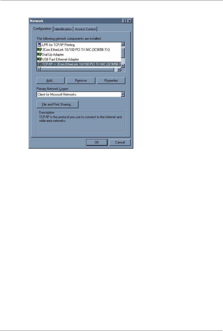
1In the Network window Configuration tab, select your network adapter's TCP/IP entry
and click Properties
2Click the IP Address tab.
• If your IP address is dynamic, select Obtain an IP address
automatically.
• If you have a static IP address, select Specify an IP address and type
your information into the IP Address and Subnet Mask fields.
Figure 111 Windows 95/98/Me: TCP/IP Properties: IP Address
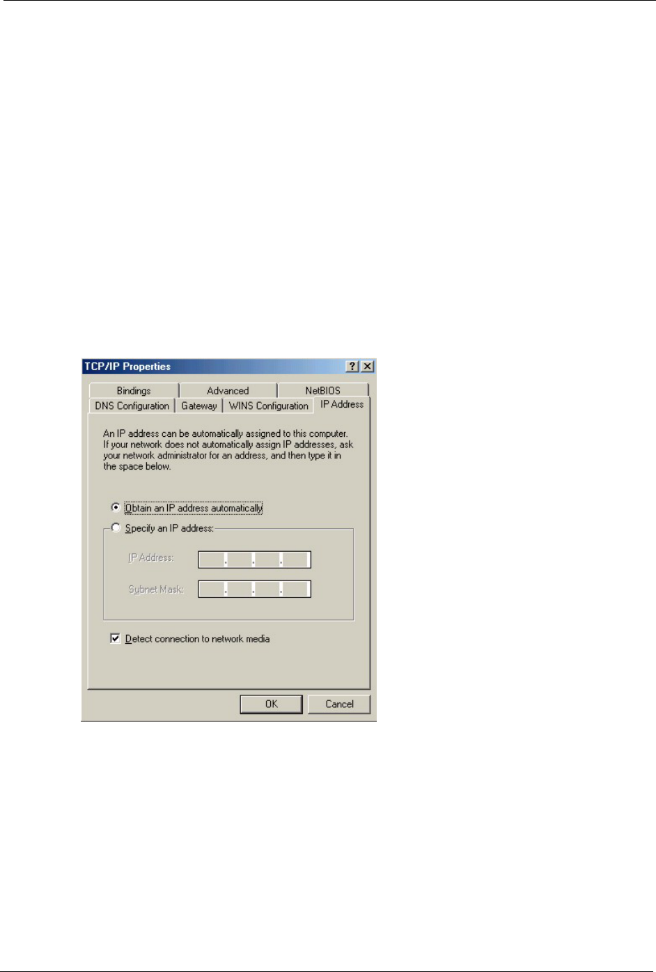
3Click the DNS Configuration tab.
• If you do not know your DNS information, select Disable DNS.
• If you know your DNS information, select Enable DNS and type the
information in the fields below (you may not need to fill them all in).
P-320W User’s Guide
176 Appendix C Setting up Your Computer’s IP Address
Figure 112 Windows 95/98/Me: TCP/IP Properties: DNS Configuration
4Click the Gateway tab.
• If you do not know your gateway’s IP address, remove previously
installed gateways.
• If you have a gateway IP address, type it in the New gateway field
and click Add.
5Click OK to save and close the TCP/IP Properties window.
6Click OK to close the Network window. Insert the Windows CD if prompted.
7Turn on your Prestige and restart your computer when prompted.
Verifying Settings
1Click Start and then Run.
2In the Run window, type "winipcfg" and then click OK to open the IP Configuration
window.
3Select your network adapter. You should see your computer's IP address, subnet mask
and default gateway.
Windows 2000/NT/XP
The following example figures use the default Windows XP GUI theme.
1Click start (Start in Windows 2000/NT), Settings, Control Panel.
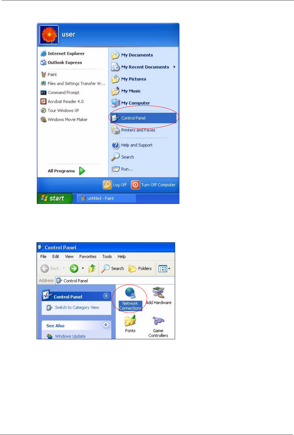
P-320W User’s Guide
Appendix C Setting up Your Computer’s IP Address 177
Figure 113 Windows XP: Start Menu
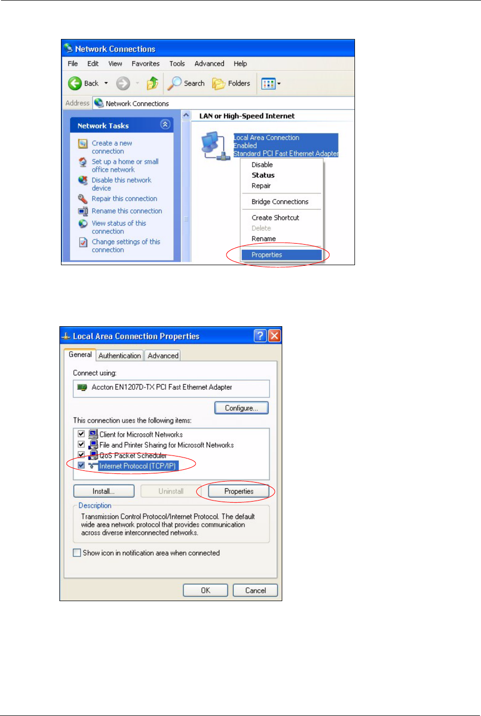
2In the Control Panel, double-click Network Connections (Network and Dial-up
Connections in Windows 2000/NT).
Figure 114 Windows XP: Control Panel
3Right-click Local Area Connection and then click Properties.
P-320W User’s Guide
178 Appendix C Setting up Your Computer’s IP Address
Figure 115 Windows XP: Control Panel: Network Connections: Properties
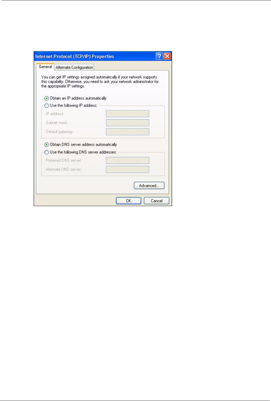
4Select Internet Protocol (TCP/IP) (under the General tab in Win XP) and then click
Properties.
Figure 116 Windows XP: Local Area Connection Properties
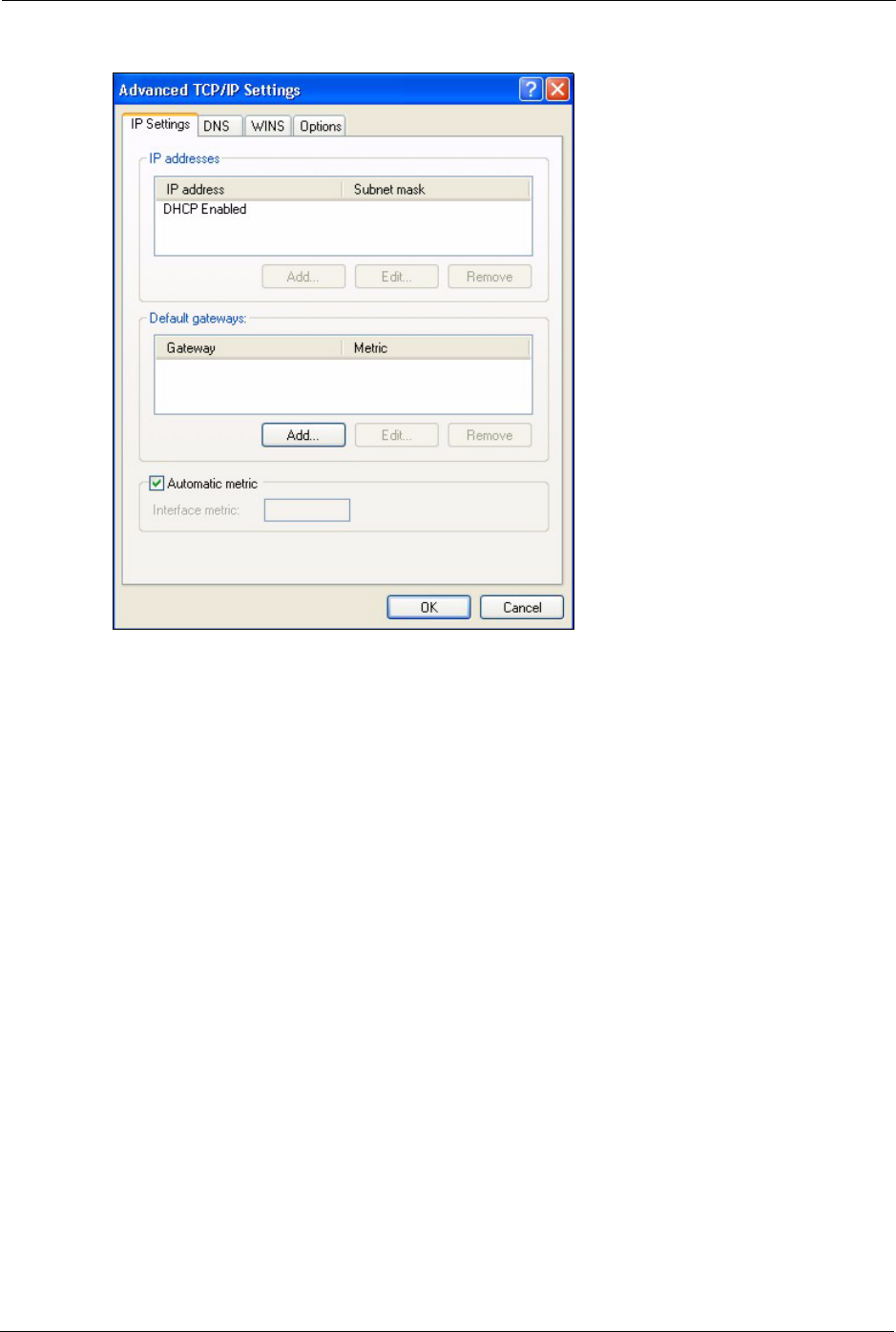
5The Internet Protocol TCP/IP Properties window opens (the General tab in Windows
XP).
• If you have a dynamic IP address click Obtain an IP address
automatically.
P-320W User’s Guide
Appendix C Setting up Your Computer’s IP Address 179
• If you have a static IP address click Use the following IP Address
and fill in the IP address, Subnet mask, and Default gateway fields.
• Click Advanced.
Figure 117 Windows XP: Internet Protocol (TCP/IP) Properties
6 If you do not know your gateway's IP address, remove any previously installed gateways
in the IP Settings tab and click OK.
Do one or more of the following if you want to configure additional IP addresses:
•In the IP Settings tab, in IP addresses, click Add.
•In TCP/IP Address, type an IP address in IP address and a subnet
mask in Subnet mask, and then click Add.
• Repeat the above two steps for each IP address you want to add.
• Configure additional default gateways in the IP Settings tab by
clicking Add in Default gateways.
•In TCP/IP Gateway Address, type the IP address of the default
gateway in Gateway. To manually configure a default metric (the
number of transmission hops), clear the Automatic metric check box
and type a metric in Metric.
• Click Add.
• Repeat the previous three steps for each default gateway you want to
add.
• Click OK when finished.
P-320W User’s Guide
180 Appendix C Setting up Your Computer’s IP Address
Figure 118 Windows XP: Advanced TCP/IP Properties
7In the Internet Protocol TCP/IP Properties window (the General tab in Windows XP):
• Click Obtain DNS server address automatically if you do not know
your DNS server IP address(es).
• If you know your DNS server IP address(es), click Use the following
DNS server addresses, and type them in the Preferred DNS server
and Alternate DNS server fields.
If you have previously configured DNS servers, click Advanced and
then the DNS tab to order them.